WO2022044523A1 - フィンチューブ熱交換器 - Google Patents
フィンチューブ熱交換器 Download PDFInfo
- Publication number
- WO2022044523A1 WO2022044523A1 PCT/JP2021/024091 JP2021024091W WO2022044523A1 WO 2022044523 A1 WO2022044523 A1 WO 2022044523A1 JP 2021024091 W JP2021024091 W JP 2021024091W WO 2022044523 A1 WO2022044523 A1 WO 2022044523A1
- Authority
- WO
- WIPO (PCT)
- Prior art keywords
- tube
- heat transfer
- predetermined
- heat exchanger
- heat
- Prior art date
- Legal status (The legal status is an assumption and is not a legal conclusion. Google has not performed a legal analysis and makes no representation as to the accuracy of the status listed.)
- Ceased
Links
Images




Classifications
-
- F—MECHANICAL ENGINEERING; LIGHTING; HEATING; WEAPONS; BLASTING
- F28—HEAT EXCHANGE IN GENERAL
- F28D—HEAT-EXCHANGE APPARATUS, NOT PROVIDED FOR IN ANOTHER SUBCLASS, IN WHICH THE HEAT-EXCHANGE MEDIA DO NOT COME INTO DIRECT CONTACT
- F28D1/00—Heat-exchange apparatus having stationary conduit assemblies for one heat-exchange medium only, the media being in contact with different sides of the conduit wall, in which the other heat-exchange medium is a large body of fluid, e.g. domestic or motor car radiators
- F28D1/02—Heat-exchange apparatus having stationary conduit assemblies for one heat-exchange medium only, the media being in contact with different sides of the conduit wall, in which the other heat-exchange medium is a large body of fluid, e.g. domestic or motor car radiators with heat-exchange conduits immersed in the body of fluid
- F28D1/04—Heat-exchange apparatus having stationary conduit assemblies for one heat-exchange medium only, the media being in contact with different sides of the conduit wall, in which the other heat-exchange medium is a large body of fluid, e.g. domestic or motor car radiators with heat-exchange conduits immersed in the body of fluid with tubular conduits
- F28D1/053—Heat-exchange apparatus having stationary conduit assemblies for one heat-exchange medium only, the media being in contact with different sides of the conduit wall, in which the other heat-exchange medium is a large body of fluid, e.g. domestic or motor car radiators with heat-exchange conduits immersed in the body of fluid with tubular conduits the conduits being straight
- F28D1/05316—Assemblies of conduits connected to common headers, e.g. core type radiators
-
- F—MECHANICAL ENGINEERING; LIGHTING; HEATING; WEAPONS; BLASTING
- F28—HEAT EXCHANGE IN GENERAL
- F28F—DETAILS OF HEAT-EXCHANGE AND HEAT-TRANSFER APPARATUS, OF GENERAL APPLICATION
- F28F1/00—Tubular elements; Assemblies of tubular elements
- F28F1/10—Tubular elements and assemblies thereof with means for increasing heat-transfer area, e.g. with fins, with projections, with recesses
- F28F1/12—Tubular elements and assemblies thereof with means for increasing heat-transfer area, e.g. with fins, with projections, with recesses the means being only outside the tubular element
- F28F1/24—Tubular elements and assemblies thereof with means for increasing heat-transfer area, e.g. with fins, with projections, with recesses the means being only outside the tubular element and extending transversely
- F28F1/32—Tubular elements and assemblies thereof with means for increasing heat-transfer area, e.g. with fins, with projections, with recesses the means being only outside the tubular element and extending transversely the means having portions engaging further tubular elements
-
- F—MECHANICAL ENGINEERING; LIGHTING; HEATING; WEAPONS; BLASTING
- F28—HEAT EXCHANGE IN GENERAL
- F28D—HEAT-EXCHANGE APPARATUS, NOT PROVIDED FOR IN ANOTHER SUBCLASS, IN WHICH THE HEAT-EXCHANGE MEDIA DO NOT COME INTO DIRECT CONTACT
- F28D1/00—Heat-exchange apparatus having stationary conduit assemblies for one heat-exchange medium only, the media being in contact with different sides of the conduit wall, in which the other heat-exchange medium is a large body of fluid, e.g. domestic or motor car radiators
- F28D1/02—Heat-exchange apparatus having stationary conduit assemblies for one heat-exchange medium only, the media being in contact with different sides of the conduit wall, in which the other heat-exchange medium is a large body of fluid, e.g. domestic or motor car radiators with heat-exchange conduits immersed in the body of fluid
- F28D1/04—Heat-exchange apparatus having stationary conduit assemblies for one heat-exchange medium only, the media being in contact with different sides of the conduit wall, in which the other heat-exchange medium is a large body of fluid, e.g. domestic or motor car radiators with heat-exchange conduits immersed in the body of fluid with tubular conduits
- F28D1/053—Heat-exchange apparatus having stationary conduit assemblies for one heat-exchange medium only, the media being in contact with different sides of the conduit wall, in which the other heat-exchange medium is a large body of fluid, e.g. domestic or motor car radiators with heat-exchange conduits immersed in the body of fluid with tubular conduits the conduits being straight
- F28D1/05316—Assemblies of conduits connected to common headers, e.g. core type radiators
- F28D1/05333—Assemblies of conduits connected to common headers, e.g. core type radiators with multiple rows of conduits or with multi-channel conduits
-
- F—MECHANICAL ENGINEERING; LIGHTING; HEATING; WEAPONS; BLASTING
- F28—HEAT EXCHANGE IN GENERAL
- F28D—HEAT-EXCHANGE APPARATUS, NOT PROVIDED FOR IN ANOTHER SUBCLASS, IN WHICH THE HEAT-EXCHANGE MEDIA DO NOT COME INTO DIRECT CONTACT
- F28D1/00—Heat-exchange apparatus having stationary conduit assemblies for one heat-exchange medium only, the media being in contact with different sides of the conduit wall, in which the other heat-exchange medium is a large body of fluid, e.g. domestic or motor car radiators
- F28D1/02—Heat-exchange apparatus having stationary conduit assemblies for one heat-exchange medium only, the media being in contact with different sides of the conduit wall, in which the other heat-exchange medium is a large body of fluid, e.g. domestic or motor car radiators with heat-exchange conduits immersed in the body of fluid
- F28D1/04—Heat-exchange apparatus having stationary conduit assemblies for one heat-exchange medium only, the media being in contact with different sides of the conduit wall, in which the other heat-exchange medium is a large body of fluid, e.g. domestic or motor car radiators with heat-exchange conduits immersed in the body of fluid with tubular conduits
- F28D1/053—Heat-exchange apparatus having stationary conduit assemblies for one heat-exchange medium only, the media being in contact with different sides of the conduit wall, in which the other heat-exchange medium is a large body of fluid, e.g. domestic or motor car radiators with heat-exchange conduits immersed in the body of fluid with tubular conduits the conduits being straight
-
- F—MECHANICAL ENGINEERING; LIGHTING; HEATING; WEAPONS; BLASTING
- F28—HEAT EXCHANGE IN GENERAL
- F28F—DETAILS OF HEAT-EXCHANGE AND HEAT-TRANSFER APPARATUS, OF GENERAL APPLICATION
- F28F1/00—Tubular elements; Assemblies of tubular elements
- F28F1/10—Tubular elements and assemblies thereof with means for increasing heat-transfer area, e.g. with fins, with projections, with recesses
- F28F1/12—Tubular elements and assemblies thereof with means for increasing heat-transfer area, e.g. with fins, with projections, with recesses the means being only outside the tubular element
- F28F1/24—Tubular elements and assemblies thereof with means for increasing heat-transfer area, e.g. with fins, with projections, with recesses the means being only outside the tubular element and extending transversely
-
- F—MECHANICAL ENGINEERING; LIGHTING; HEATING; WEAPONS; BLASTING
- F28—HEAT EXCHANGE IN GENERAL
- F28F—DETAILS OF HEAT-EXCHANGE AND HEAT-TRANSFER APPARATUS, OF GENERAL APPLICATION
- F28F1/00—Tubular elements; Assemblies of tubular elements
- F28F1/10—Tubular elements and assemblies thereof with means for increasing heat-transfer area, e.g. with fins, with projections, with recesses
- F28F1/12—Tubular elements and assemblies thereof with means for increasing heat-transfer area, e.g. with fins, with projections, with recesses the means being only outside the tubular element
- F28F1/24—Tubular elements and assemblies thereof with means for increasing heat-transfer area, e.g. with fins, with projections, with recesses the means being only outside the tubular element and extending transversely
- F28F1/30—Tubular elements and assemblies thereof with means for increasing heat-transfer area, e.g. with fins, with projections, with recesses the means being only outside the tubular element and extending transversely the means being attachable to the element
-
- F—MECHANICAL ENGINEERING; LIGHTING; HEATING; WEAPONS; BLASTING
- F28—HEAT EXCHANGE IN GENERAL
- F28F—DETAILS OF HEAT-EXCHANGE AND HEAT-TRANSFER APPARATUS, OF GENERAL APPLICATION
- F28F2250/00—Arrangements for modifying the flow of the heat exchange media, e.g. flow guiding means; Particular flow patterns
- F28F2250/10—Particular pattern of flow of the heat exchange media
Definitions
- the present invention relates to a fin tube heat exchanger.
- Fin tube heat exchangers are generally used in industrial heat exchangers.
- a plurality of heat transfer tubes arranged in a direction intersecting the flow direction of the heat exchange air, and a plurality of fins (heat transfer plates) arranged in the tube axial direction of these heat transfer tubes.
- a liquid medium is passed through the heat transfer tube, and a gas body (heat exchange air) is applied to the outer peripheral surface of the heat transfer tube and the fins to exchange heat.
- the plurality of fins contributes to an increase in the amount of heat transfer by expanding the heat transfer area.
- Japanese Unexamined Patent Publication No. 2013-92306 Japanese Unexamined Patent Publication No. 2011-237047 Japanese Unexamined Patent Publication No. 2008-57944 Japanese Unexamined Patent Publication No. 61-285395
- the present invention has been made in view of this point, and one of the objects of the present invention is to provide a fin tube heat exchanger capable of reducing the pressure loss of the heat exchange air while maintaining the heat exchange performance.
- the fin tube heat exchanger comprises a tube row in which a plurality of heat transfer tubes are arranged side by side at a predetermined pitch in a first direction intersecting the flow direction of heat exchange air, and the first direction and the above-mentioned first direction.
- a fin tube heat exchanger in which a plurality of tube rows are arranged at predetermined intervals in a second direction intersecting the predetermined tube rows with respect to other adjacent tube rows in the second direction.
- the heat transfer tubes of the predetermined tube row are arranged offset to the heat transfer tube side of the other adjacent tube rows when viewed from the flow direction of the heat exchange air. There is.
- FIG. 1 It is a schematic perspective view of the fin tube heat exchanger which concerns on this embodiment. It is a partially enlarged view of the fin tube heat exchanger which concerns on this embodiment. It is sectional drawing of the fin tube heat exchanger which concerns on a comparative example. It is sectional drawing of the fin tube heat exchanger which concerns on 1st Embodiment. It is a graph which shows the heat exchange performance ratio and the pressure loss ratio according to the position of a heat transfer tube. It is sectional drawing of the fin tube heat exchanger which concerns on 1st modification. It is sectional drawing of the fin tube heat exchanger which concerns on 2nd Embodiment.
- the fin tube heat exchanger according to the present invention is suitably used for, for example, a radiator such as a condenser installed in a geothermal power generation facility.
- a radiator such as a condenser installed in a geothermal power generation facility.
- the fin tube heat exchanger according to the present invention is not limited to this, and any heat exchange such as an air-cooled heat exchanger of a petrochemical factory or an refinery factory, an air-cooled condenser of an incinerator, etc. Can be applied to vessels.
- the first direction in which a plurality of heat transfer tubes are lined up is defined as the X direction
- the second direction in which a plurality of tube rows are lined up is defined as the Y direction
- the axial direction (extending direction) of the heat transfer tubes is defined as the Z direction. I will do it.
- the illustrated X, Y, and Z axes are orthogonal to each other. Further, depending on the case, the X direction may be referred to as a left-right direction, the Y direction may be referred to as a vertical direction, and the Z direction may be referred to as a front-back direction.
- the directions are words used for convenience of explanation, and the correspondence with each of the XYZ directions may change depending on the mounting posture of the fin tube heat exchanger.
- the side on which the intake air (heat exchange air) is sucked into the fin tube heat exchanger is referred to as the lower surface side
- the side on which the intake air is blown out is referred to as the upper surface side.
- the plan view means the case where the upper surface of the fin tube heat exchanger is viewed from the positive side in the Y direction
- the cross-sectional view means the axial direction (Z direction) of the heat transfer tube. It shall mean the cross section when viewed from the entanglement.
- FIG. 1 is a schematic perspective view of the fin tube heat exchanger according to the present embodiment.
- FIG. 2 is a partially enlarged view of the fin tube heat exchanger according to the present embodiment.
- a part of the fin tube is excerpted and shown, and a cross section of the part of the fin tube is shown.
- the fin tube heat exchanger 1 (hereinafter, simply referred to as a heat exchanger) according to the present embodiment is composed of, for example, a radiator for air-cooled geothermal binary power generation. Although the details will be described later, the heat exchanger 1 realizes heat exchange between the refrigerant flowing inside the heat transfer tube 20 and the air flowing outside the heat transfer tube 20.
- the heat exchanger 1 is formed in a flat shape having a predetermined thickness in the vertical direction (Y direction) in a rectangular shape in a plan view.
- the heat exchanger 1 is configured by arranging a plurality of heat transfer tubes 20 extending in the Z direction side by side in the X and Y directions, and connecting both ends of the heat transfer tubes 20 in the Z direction with a pair of header portions 3. ..
- FIG. 1 for convenience of explanation, only the header portion 3 on one end side (negative side in the Z direction) of the pair of header portions 3 is shown.
- the heat transfer tube 20 has a hollow cylindrical shape (circular tube shape) having a predetermined outer diameter D (see FIG. 4), and extends in the Z direction, which is the front-rear direction.
- a fluid serving as a refrigerant can flow inside the heat transfer tube 20.
- hot water can be used as the refrigerant introduced into the heat transfer tube 20.
- the refrigerant is not limited to hot water, and other fluids (pentane, CFC substitutes, etc.) may be used. Although the details will be described later, the surface temperature of the heat transfer tube 20 changes according to the temperature of the refrigerant flowing inside.
- a plurality of fins 21 are provided on the outer peripheral surface of the heat transfer tube 20.
- the fin 21 is formed of a plate-like body having a generally annular shape and a thickness in the Z direction when viewed from the axial direction (Z direction) of the heat transfer tube 20.
- the fins 21 may be joined to the outer peripheral surface of the heat transfer tube 20 by, for example, a tube expansion process for expanding a part or all of the outer diameter of the heat transfer tube 20.
- a plurality of fins 21 are arranged on the outer peripheral surface of the heat transfer tube 20 at predetermined intervals in the Z direction.
- the plurality of fins 21 have the same shape.
- the heat transfer tube 20 and the plurality of fins 21 may be collectively referred to as a fin tube 2.
- a plurality of heat transfer tubes 20 (fin tubes 2) configured in this way are arranged in the X direction (first direction) at a predetermined pitch P1 to form one tube row 22 (see FIG. 4). .. More specifically, the plurality of heat transfer tubes 20 constituting one tube row 22 are arranged side by side in the direction (X direction) intersecting the flow direction (vertical direction) of the heat exchange air. Further, in the heat exchanger 1, a plurality of tube rows 22 are arranged side by side in the Y direction (second direction) with a predetermined interval P2. The layout of the plurality of tube rows 22 and the plurality of heat transfer tubes 20 will be described later. Further, a plurality of tube rows 22 may be collectively referred to as a tube bundle. It is preferable that the predetermined outer diameters D of the plurality of heat transfer tubes 20 are all the same size.
- a pair of header portions 3 are connected to the shaft end of the heat transfer tube 20.
- the header portion 3 has a rectangular parallelepiped shape corresponding to the widths of the tube bundle in the X direction and the Y direction, and is composed of a tank having a hollow inside. Shaft ends of a plurality of heat transfer tubes 20 penetrate through the side surface of the header portion 3. The internal space of the heat transfer tube 20 communicates with the internal space of the header portion 3. Further, a refrigerant inlet / outlet 30 is provided on the upper surface and the lower surface of the header portion 3. That is, the internal space of the header portion 3 and the internal space of the heat transfer tube 20 form a flow path for the refrigerant.
- a blower (not shown) is arranged facing each other on the upper surface side of the heat exchanger 1 configured in this way.
- the blower sucks air (heat exchange air) from below the heat exchanger 1 and sends it out to the upper external space. That is, the heat exchange air circulates in the vertical direction of the heat exchanger 1.
- the sucked up heat exchange air is warmed by heat exchange in the heat exchanger 1 and then released to the outside. That is, the lower surface side of the heat exchanger 1 is the upstream side and the upper surface side of the heat exchanger 1 is the downstream side with respect to the flow direction of the heat exchange air.
- the flow direction of the heat exchange air is from the negative side in the Y direction to the positive side in the Y direction.
- the first direction, the X direction intersects the flow direction of the heat exchange air.
- the Y direction, which is the second direction is orthogonal to the first direction and coincides with the flow direction of the heat exchange air.
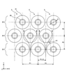
- FIG. 3 is a schematic cross-sectional view of the fin tube heat exchanger according to the comparative example.
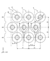
- FIG. 4 is a schematic cross-sectional view of the fin tube heat exchanger according to the first embodiment.
- the heat exchanger configuration according to the comparative example of FIG. 3 is shown by the same reference numerals as the existing configurations because the fin tube layout is different.
- the predetermined tube row 22 is arranged so as to be offset in the X direction with respect to the other tube rows 22 adjacent to each other in the Y direction. More specifically, the predetermined tube row 22 is arranged at a position (hereinafter referred to as a reference position) deviated in the X direction by a pitch P1 / 2 which is half of the predetermined pitch P1 with respect to the other tube row 22. Such an arrangement of the tube rows 22 may be referred to as a staggered arrangement. In the staggered arrangement, the plurality of tube rows 22 are staggered with a half pitch P1 / 2 offset. Further, in FIG. 3, for example, the outer surface of the heat transfer tube 20 of the predetermined tube row 22 and the outer surface of the heat transfer tube 20 of another adjacent tube row 22 are separated by a distance X1 from the flow direction of the heat exchange air. ..
- the blower used for the radiator of air-cooled geothermal binary power generation as described above is driven by the power generated by the system. Therefore, if the pressure loss is high, the power consumption of the blower increases, and as a result, the transmitted power decreases. Therefore, it is required to reduce the pressure loss and increase the transmitted power.
- the inventors of the present invention focused on the arrangement of the heat transfer tube 20 which is a component of the heat exchanger 1 and came up with the present invention.
- the tube row 22 is formed by arranging a plurality of heat transfer tubes 20 side by side at a predetermined pitch P1 in the X direction. Further, a plurality of tube rows 22 are arranged side by side with a predetermined interval P2 in the Y direction.
- the predetermined tube rows 22 are arranged so as to be offset in the X direction with respect to the other tube rows 22 adjacent to each other in the Y direction.
- the heat transfer tube 20 of the predetermined tube row 22 is arranged unevenly on the heat transfer tube 20 side of another adjacent tube row 22 when viewed from the flow direction of the heat exchange air.
- the predetermined tube row 22 is located on one side in the X direction (for example, the positive side) of the reference position shifted in the X direction by the pitch P1 / 2 which is half of the predetermined pitch P1 with respect to the other tube row 22. ) Is biased by the distance X2. That is, the predetermined tube row 22 is arranged at a position deviated from the other tube row 22 by a distance (P1 / 2 ⁇ X2).
- the predetermined tube rows 22 are arranged slightly offset from the staggered arrangement, so that the heat exchange air flowing in from the lower surface side of the heat exchanger 1 is directly directed toward the center of the heat transfer tube 20. There is no collision and it is possible to reduce the pressure loss. Further, even if the predetermined tube row 22 is slightly displaced from the staggered arrangement, the heat exchange air flowing through the upstream side (negative side in the Y direction) tube row 22 is predetermined in the downstream side tube row 22 due to the Coanda effect. It flows so as to be attracted to the outer peripheral surface of the heat transfer tube 20. Therefore, in the tube row 22 on the downstream side, the heat exchange air can be divided into two left and right in the X direction without flowing unevenly. As a result, it is possible to reduce the pressure loss of the heat exchange air while maintaining the heat exchange performance.
- the heat transfer tube 20 of the predetermined tube row 22 is located on the outer surface of the heat transfer tube 20 of another adjacent tube row 22 when viewed from the flow direction of the heat exchange air. It is preferably arranged so as to be in contact with each other. That is, it is preferable that the distance X1 between the outer surface of the heat transfer tube 20 of the predetermined tube row 22 shown in FIG. 3 and the outer surface of the heat transfer tube 20 of another adjacent tube row 22 is zero.
- the heat exchange air flowing through the upstream tube row 22 does not flow unevenly to one side in the downstream tube row 22 due to the Coanda effect, and air flows to both the left and right sides. ..
- the heat exchange air flowing through the tube row 22 on the downstream side is increased, it is possible to reduce the pressure loss.
- the deviation amount of the predetermined tube row 22 with respect to the staggered arrangement is within a predetermined range.
- the distance between the centers of the heat transfer tube 20 of the predetermined tube row 22 and the heat transfer tube 20 of the other adjacent tube row 22 when viewed from the flow direction of the heat exchange air is S, and the outer diameter of the heat transfer tube 20 is set to S.
- Is D it is preferable to satisfy the relationship of 0.95 ⁇ S / D ⁇ 1.38.
- FIG. 5 is a graph showing a heat exchange performance ratio and a pressure loss ratio according to the position of the heat transfer tube 20.
- the horizontal axis shows the ratio S / D of the above-mentioned center-to-center distance S and the outer diameter D of the heat transfer tube
- the vertical axis shows the heat exchange performance ratio or the pressure loss ratio.
- the solid line represents the heat exchange performance ratio
- the broken line represents the pressure loss ratio.
- the staggered arrangement shown in FIG. 3 is given as an example.
- the heat exchange performance ratio and the pressure loss ratio in the staggered arrangement will be described as "1" as a reference.
- the amount of deviation of the predetermined tube row 22 is increased from the staggered arrangement, that is, the heat transfer tube 20 of the predetermined tube row 22 is brought closer to the heat transfer tube 20 of another adjacent tube row 22 (the center-to-center distance S is reduced). Then, the S / D gradually becomes smaller.
- the pressure loss ratio gradually decreases as the S / D decreases. Further, in the range of 0.95 ⁇ S / D ⁇ 1.38, the heat exchange performance ratio is almost constant at “1”. When the S / D is less than 0.95, the heat exchange performance ratio gradually decreases. That is, in the range of 0.95 ⁇ S / D ⁇ 1.38, it is possible to reduce the pressure loss ratio while maintaining the heat exchange performance ratio at the same level as the conventional staggered arrangement.
- FIG. 6 is a schematic cross-sectional view of the fin tube heat exchanger according to the first modification.
- the heat transfer tube 20 of the predetermined tube row 22 is at least a part away from the heat transfer tube 20 of another adjacent tube row 22 when viewed from the flow direction of the heat exchange air. It is arranged so that only X3 overlaps. In this case, it is preferable that the distance X3 is set so as to be within the above-mentioned S / D range (more specifically, 0.95 ⁇ S / D ⁇ 1). Even with such a configuration, it is possible to reduce the pressure loss ratio while maintaining the heat exchange performance ratio equivalent to that of the conventional staggered arrangement.
- the predetermined tube row 22 is X with respect to the other tube row 22 with respect to the reference position shifted in the X direction by half the pitch P1 / 2 of the predetermined pitch P1.
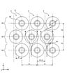
- FIG. 7 is a schematic cross-sectional view of the fin tube heat exchanger according to the second embodiment.
- the predetermined tube row 22 is staggered with respect to the staggered arrangement.
- the second embodiment shown in FIG. 7 differs from the first embodiment in that the plurality of tube rows 22 are staggered, while the entire heat exchanger 1 is tilted by a predetermined angle. Therefore, the above-mentioned configurations are designated by the same reference numerals and the description thereof will be omitted as appropriate.
- the predetermined tube row 22 is arranged at a reference position shifted in the first direction by a pitch P1 / 2, which is half of the predetermined pitch P1 with respect to the other tube row 22. Further, the first direction is inclined at a predetermined angle ⁇ with respect to the direction (X direction) orthogonal to the flow direction (Y direction) of the heat exchange air. Also in this case, the heat transfer tubes 20 of the predetermined tube row 22 are arranged unevenly toward the heat transfer tubes 20 side of the other adjacent tube rows 22 when viewed from the flow direction of the heat exchange air.
- the inclination angle ⁇ of the heat exchanger 1 is preferably, for example, 9 degrees. At this angle, as shown in FIG. 7, the heat transfer tube 20 of the predetermined tube row 22 comes into contact with the outer surface of the heat transfer tube 20 of another adjacent tube row 22 when viewed from the flow direction of the heat exchange air. Is placed in. As a result, even in the second embodiment, it is possible to reduce the pressure loss ratio while maintaining the heat exchange performance ratio at the same level as the conventional one.
- the inclination angle ⁇ of the heat exchanger 1 is not limited to this, and can be changed as appropriate. Further, by inclining the entire heat exchanger 1 at an angle, the number of heat transfer tubes 20 (fin tubes 2) arranged can be increased, and the heat exchange performance can be improved. Furthermore, since it is only necessary to incline the heat exchanger 1, the existing configuration can be effectively utilized and the design man-hours can be reduced.
- the shape, number of arrangements, layout, etc. of the heat transfer tubes 20 are not limited to this, and can be appropriately changed. Similarly, the number of tube rows 22 and the amount of shift can be appropriately changed.
- the present embodiment is not limited to the above-described embodiment and modification, and may be variously changed, replaced, or modified without departing from the spirit of the technical idea. Further, if the technical idea can be realized in another way by the advancement of the technology or another technology derived from it, it may be carried out by the method. Therefore, the claims cover all embodiments that may be included within the scope of the technical idea.
- the fin tube heat exchanger includes a tube row in which a plurality of heat transfer tubes are arranged side by side at a predetermined pitch in a first direction intersecting the flow direction of the heat exchange air, and has the same as the first direction.
- a fin tube heat exchanger in which a plurality of tube rows are arranged at predetermined intervals in a second direction intersecting the predetermined tube rows with respect to other adjacent tube rows in the second direction.
- the heat transfer tubes of the predetermined tube row are arranged offset to the heat transfer tube side of the other adjacent tube rows when viewed from the flow direction of the heat exchange air. There is.
- the predetermined tube row is the first from the reference position deviated in the first direction by half the pitch of the predetermined pitch with respect to the other tube row. It is unevenly arranged on one side in the direction of 1.
- the predetermined tube row is arranged at a reference position shifted in the first direction by half the pitch of the predetermined pitch with respect to the other tube row.
- the first direction is inclined at a predetermined angle with respect to the direction orthogonal to the flow direction of the heat exchange air.
- the predetermined angle is 9 degrees.
- the heat transfer tube of the predetermined tube row is in contact with the outer surface of the heat transfer tube of the other adjacent tube row when viewed from the flow direction of the heat exchange air. Have been placed.
- the heat transfer tube of the predetermined tube row is at least partially overlapped with the heat transfer tube of the other adjacent tube rows when viewed from the flow direction of the heat exchange air. Is located in.
- the distance between the centers of the heat transfer tube of the predetermined tube row and the heat transfer tube of the other adjacent tube row is S, and the outer diameter of the heat transfer tube is D. Then, the relationship of 0.95 ⁇ S / D ⁇ 1.38 is satisfied.
- the present invention has the effect of reducing the pressure loss of the heat exchange air while maintaining the heat exchange performance, and in particular, the fin tube heat used as a radiator for geothermal binary power generation. Useful for exchangers.
Landscapes
- Engineering & Computer Science (AREA)
- Physics & Mathematics (AREA)
- Thermal Sciences (AREA)
- Mechanical Engineering (AREA)
- General Engineering & Computer Science (AREA)
- Geometry (AREA)
- Heat-Exchange Devices With Radiators And Conduit Assemblies (AREA)
Abstract
Description
上記実施の形態に係るフィンチューブ熱交換器は、熱交換空気の流通方向と交差する第1の方向に所定ピッチで複数の伝熱管が並べて配置されたチューブ列を備え、前記第1の方向と交差する第2の方向に複数のチューブ列が所定間隔を空けて配置されたフィンチューブ熱交換器であって、所定のチューブ列は、前記第2の方向で隣り合う他のチューブ列に対して前記第1の方向にずれて配置されており、前記熱交換空気の流通方向からみて、前記所定のチューブ列の伝熱管は、隣接する前記他のチューブ列の伝熱管側に偏って配置されている。
Claims (7)
- 熱交換空気の流通方向と交差する第1の方向に所定ピッチで複数の伝熱管が並べて配置されたチューブ列を備え、前記第1の方向と交差する第2の方向に複数のチューブ列が所定間隔を空けて配置されたフィンチューブ熱交換器であって、
所定のチューブ列は、前記第2の方向で隣り合う他のチューブ列に対して前記第1の方向にずれて配置されており、
前記熱交換空気の流通方向からみて、前記所定のチューブ列の伝熱管は、隣接する前記他のチューブ列の伝熱管側に偏って配置されている、フィンチューブ熱交換器。 - 前記所定のチューブ列は、前記他のチューブ列に対して前記所定ピッチの半分のピッチだけ前記第1の方向にずれた基準位置よりも前記第1の方向の一方側に偏って配置されている、請求項1に記載のフィンチューブ熱交換器。
- 前記所定のチューブ列は、前記他のチューブ列に対して前記所定ピッチの半分のピッチだけ前記第1の方向にずれた基準位置に配置されており、
前記第1の方向は、前記熱交換空気の流通方向に直交する方向に対して所定角度で傾斜している、請求項1に記載のフィンチューブ熱交換器。 - 前記所定角度は9度である、請求項3に記載のフィンチューブ熱交換器。
- 前記熱交換空気の流通方向からみて、前記所定のチューブ列の伝熱管は、隣接する前記他のチューブ列の伝熱管の外面に接触するように配置されている、請求項1から請求項4のいずれかに記載のフィンチューブ熱交換器。
- 前記熱交換空気の流通方向からみて、前記所定のチューブ列の伝熱管は、隣接する前記他のチューブ列の伝熱管に少なくとも一部が重なるように配置されている、請求項1から請求項4のいずれかに記載のフィンチューブ熱交換器。
- 前記所定のチューブ列の伝熱管と隣接する前記他のチューブ列の伝熱管との中心間距離をSとし、前記伝熱管の外径をDとすると、
0.95≦S/D≦1.38の関係を満たす、請求項1から請求項6のいずれかに記載のフィンチューブ熱交換器。
Priority Applications (6)
| Application Number | Priority Date | Filing Date | Title |
|---|---|---|---|
| CN202180010764.7A CN115003978A (zh) | 2020-08-24 | 2021-06-25 | 翅片管换热器 |
| NZ790900A NZ790900B2 (en) | 2021-06-25 | Fin tube heat exchanger | |
| JP2022545483A JP7452672B2 (ja) | 2020-08-24 | 2021-06-25 | フィンチューブ熱交換器 |
| PH1/2022/551930A PH12022551930A1 (en) | 2020-08-24 | 2021-06-25 | Finned tube heat exchanger |
| KR1020227025423A KR102772853B1 (ko) | 2020-08-24 | 2021-06-25 | 핀 튜브 열 교환기 |
| US17/876,075 US12259198B2 (en) | 2020-08-24 | 2022-07-28 | Finned tube heat exchanger |
Applications Claiming Priority (2)
| Application Number | Priority Date | Filing Date | Title |
|---|---|---|---|
| JP2020140874 | 2020-08-24 | ||
| JP2020-140874 | 2020-08-24 |
Related Child Applications (1)
| Application Number | Title | Priority Date | Filing Date |
|---|---|---|---|
| US17/876,075 Continuation US12259198B2 (en) | 2020-08-24 | 2022-07-28 | Finned tube heat exchanger |
Publications (1)
| Publication Number | Publication Date |
|---|---|
| WO2022044523A1 true WO2022044523A1 (ja) | 2022-03-03 |
Family
ID=80354920
Family Applications (1)
| Application Number | Title | Priority Date | Filing Date |
|---|---|---|---|
| PCT/JP2021/024091 Ceased WO2022044523A1 (ja) | 2020-08-24 | 2021-06-25 | フィンチューブ熱交換器 |
Country Status (6)
| Country | Link |
|---|---|
| US (1) | US12259198B2 (ja) |
| JP (1) | JP7452672B2 (ja) |
| KR (1) | KR102772853B1 (ja) |
| CN (1) | CN115003978A (ja) |
| PH (1) | PH12022551930A1 (ja) |
| WO (1) | WO2022044523A1 (ja) |
Families Citing this family (1)
| Publication number | Priority date | Publication date | Assignee | Title |
|---|---|---|---|---|
| WO2022044523A1 (ja) * | 2020-08-24 | 2022-03-03 | 富士電機株式会社 | フィンチューブ熱交換器 |
Citations (10)
| Publication number | Priority date | Publication date | Assignee | Title |
|---|---|---|---|---|
| JPS59103071U (ja) * | 1982-12-24 | 1984-07-11 | 三菱重工業株式会社 | 熱交換器 |
| JPS646699A (en) * | 1987-06-26 | 1989-01-11 | Matsushita Refrigeration | Heat exchanger with fin |
| JPH0926283A (ja) * | 1995-07-07 | 1997-01-28 | Sakushiyon Gas Kikan Seisakusho:Kk | 多管式熱交換器 |
| JPH10332290A (ja) * | 1997-05-31 | 1998-12-15 | Samsung Electron Co Ltd | 空気調和機の熱交換器 |
| JP2000274982A (ja) * | 1999-03-23 | 2000-10-06 | Mitsubishi Electric Corp | 熱交換器及びそれを用いた空調冷凍装置 |
| JP2001317890A (ja) * | 2000-05-01 | 2001-11-16 | Matsushita Electric Ind Co Ltd | フィン付き熱交換器 |
| JP2007170733A (ja) * | 2005-12-21 | 2007-07-05 | Rinnai Corp | 潜熱回収型熱交換器 |
| JP2007322061A (ja) * | 2006-05-31 | 2007-12-13 | Daikin Ind Ltd | 空気調和装置 |
| JP2012225545A (ja) * | 2011-04-18 | 2012-11-15 | Mitsubishi Electric Corp | 熱交換器及びこの熱交換器を備えた空気調和機 |
| JP2012531574A (ja) * | 2009-06-29 | 2012-12-10 | トレイン・インターナショナル・インコーポレイテッド | ハイブリッド型孔パターンを有する平板フィン |
Family Cites Families (24)
| Publication number | Priority date | Publication date | Assignee | Title |
|---|---|---|---|---|
| US2813698A (en) * | 1954-06-23 | 1957-11-19 | Roland L Lincoln | Heat exchanger |
| US3116134A (en) * | 1961-01-23 | 1963-12-31 | Gen Electric | Combination heat exchanger and degasifier |
| US3163208A (en) * | 1961-09-29 | 1964-12-29 | Gen Electric | Brace for finned tubes |
| US3267914A (en) * | 1964-10-27 | 1966-08-23 | Foster Wheeler Corp | Economizer support |
| CH428814A (de) * | 1965-01-21 | 1967-01-31 | Sulzer Ag | Abstützung für ein Bündel quer angeströmter Rohre eines Wärmeübertragers |
| US3391732A (en) * | 1966-07-29 | 1968-07-09 | Mesabi Cores Inc | Radiator construction |
| US3627034A (en) * | 1970-03-12 | 1971-12-14 | Ingersoll Rand Co | Heat exchanger mounting base and heat exchanger assembly |
| JPS5758081A (en) * | 1980-09-25 | 1982-04-07 | Agency Of Ind Science & Technol | Mist cooling type heat exchanger |
| US4552292A (en) * | 1982-11-12 | 1985-11-12 | General Electric Company | Heat exchanger |
| US4660627A (en) * | 1984-07-16 | 1987-04-28 | Deck Brent D | Heat exchanging with slowly rotating finned elements |
| JPS61285395A (ja) | 1985-06-11 | 1986-12-16 | Matsushita Electric Ind Co Ltd | 熱交換器 |
| DE3528499C1 (de) * | 1985-08-08 | 1987-03-12 | Konvekta Gmbh | Waermetauscher-Einrichtung mit Waermetauscher-Rohren und blechfoermigen Lamellen |
| US4854381A (en) * | 1988-04-11 | 1989-08-08 | Paul Mikula | Heat exchanger device |
| JP2611595B2 (ja) * | 1992-01-27 | 1997-05-21 | 三菱電機株式会社 | 空気調和装置 |
| US5632149A (en) * | 1994-11-28 | 1997-05-27 | Sanyo Electric Company, Ltd. | Heat exchanger for a gas compression/expansion apparatus and a method of manufacturing thereof |
| US6964297B1 (en) * | 1998-07-14 | 2005-11-15 | L & M Radiator, Inc. | Removable tube heat exchanger and header plate |
| US20040163800A1 (en) * | 2003-02-25 | 2004-08-26 | Richardson Curtis A. | Heat exchanger for heating of fuel cell combustion air |
| US7650933B2 (en) * | 2005-03-14 | 2010-01-26 | Allied Engineering Company, Division Of E-Z-Rect Manufacturing Ltd. | Baffle for sealed combustion chamber |
| AU2007253808B2 (en) * | 2006-05-19 | 2010-12-09 | L & M Radiator, Inc. | Removable tube heat exchanger with retaining assembly |
| JP4884140B2 (ja) | 2006-09-04 | 2012-02-29 | パナソニック株式会社 | フィンチューブ型熱交換器およびヒートポンプ装置 |
| JP2011237047A (ja) | 2010-04-30 | 2011-11-24 | Daikin Industries Ltd | 空気調和装置の熱交換器 |
| JP2013092306A (ja) | 2011-10-26 | 2013-05-16 | Panasonic Corp | フィンチューブ熱交換器 |
| US12449205B2 (en) * | 2020-03-10 | 2025-10-21 | University Of Maryland, College Park | Cross-flow heat exchanger systems and methods for fabrication thereof |
| WO2022044523A1 (ja) * | 2020-08-24 | 2022-03-03 | 富士電機株式会社 | フィンチューブ熱交換器 |
-
2021
- 2021-06-25 WO PCT/JP2021/024091 patent/WO2022044523A1/ja not_active Ceased
- 2021-06-25 JP JP2022545483A patent/JP7452672B2/ja active Active
- 2021-06-25 KR KR1020227025423A patent/KR102772853B1/ko active Active
- 2021-06-25 PH PH1/2022/551930A patent/PH12022551930A1/en unknown
- 2021-06-25 CN CN202180010764.7A patent/CN115003978A/zh active Pending
-
2022
- 2022-07-28 US US17/876,075 patent/US12259198B2/en active Active
Patent Citations (10)
| Publication number | Priority date | Publication date | Assignee | Title |
|---|---|---|---|---|
| JPS59103071U (ja) * | 1982-12-24 | 1984-07-11 | 三菱重工業株式会社 | 熱交換器 |
| JPS646699A (en) * | 1987-06-26 | 1989-01-11 | Matsushita Refrigeration | Heat exchanger with fin |
| JPH0926283A (ja) * | 1995-07-07 | 1997-01-28 | Sakushiyon Gas Kikan Seisakusho:Kk | 多管式熱交換器 |
| JPH10332290A (ja) * | 1997-05-31 | 1998-12-15 | Samsung Electron Co Ltd | 空気調和機の熱交換器 |
| JP2000274982A (ja) * | 1999-03-23 | 2000-10-06 | Mitsubishi Electric Corp | 熱交換器及びそれを用いた空調冷凍装置 |
| JP2001317890A (ja) * | 2000-05-01 | 2001-11-16 | Matsushita Electric Ind Co Ltd | フィン付き熱交換器 |
| JP2007170733A (ja) * | 2005-12-21 | 2007-07-05 | Rinnai Corp | 潜熱回収型熱交換器 |
| JP2007322061A (ja) * | 2006-05-31 | 2007-12-13 | Daikin Ind Ltd | 空気調和装置 |
| JP2012531574A (ja) * | 2009-06-29 | 2012-12-10 | トレイン・インターナショナル・インコーポレイテッド | ハイブリッド型孔パターンを有する平板フィン |
| JP2012225545A (ja) * | 2011-04-18 | 2012-11-15 | Mitsubishi Electric Corp | 熱交換器及びこの熱交換器を備えた空気調和機 |
Also Published As
| Publication number | Publication date |
|---|---|
| NZ790900A (en) | 2025-08-29 |
| CN115003978A (zh) | 2022-09-02 |
| JP7452672B2 (ja) | 2024-03-19 |
| KR102772853B1 (ko) | 2025-02-24 |
| KR20220116296A (ko) | 2022-08-22 |
| US12259198B2 (en) | 2025-03-25 |
| JPWO2022044523A1 (ja) | 2022-03-03 |
| US20220364799A1 (en) | 2022-11-17 |
| PH12022551930A1 (en) | 2023-11-29 |
Similar Documents
| Publication | Publication Date | Title |
|---|---|---|
| KR100809514B1 (ko) | 핀 구조체 및 이 핀 구조체를 내장한 전열관 및 이전열관을 조립한 열 교환기 | |
| CN100373121C (zh) | 扁平管式热交换器 | |
| US9631876B2 (en) | Heat exchanger | |
| US9714794B2 (en) | Heat exchanger tube having fins with varying louver inclination angle | |
| CN1157904A (zh) | 冷媒蒸发器 | |
| US11293702B2 (en) | Heat exchanger and hot water apparatus | |
| KR101977817B1 (ko) | 열교환기 | |
| JP6679810B1 (ja) | 熱交換チューブ、熱交換チューブの製造方法、及び熱交換器 | |
| CN112368535B (zh) | 热交换器 | |
| WO2022044523A1 (ja) | フィンチューブ熱交換器 | |
| CN109470075B (zh) | 翅片和换热器 | |
| WO2017094366A1 (ja) | 熱交換器用フィン | |
| CN113383205A (zh) | 换热器 | |
| JP7396945B2 (ja) | 熱交換器 | |
| JP2006207966A (ja) | 熱交換器 | |
| JP2018004090A (ja) | 空気調和機の室内機 | |
| JP2002195774A (ja) | 空気熱交換器 | |
| KR100819010B1 (ko) | 열교환기 | |
| JP2020139722A (ja) | 熱交換器及び冷却構造 | |
| US20230221084A1 (en) | Heat exchanger | |
| JP2008185307A (ja) | 熱交換器用フィン | |
| KR200311823Y1 (ko) | 열교환기용튜브 | |
| JP2000220972A (ja) | Egrガス冷却装置 | |
| KR20250155155A (ko) | 열교환기 | |
| WO2024116495A1 (ja) | 熱交換器 |
Legal Events
| Date | Code | Title | Description |
|---|---|---|---|
| 121 | Ep: the epo has been informed by wipo that ep was designated in this application |
Ref document number: 21860953 Country of ref document: EP Kind code of ref document: A1 |
|
| ENP | Entry into the national phase |
Ref document number: 20227025423 Country of ref document: KR Kind code of ref document: A |
|
| ENP | Entry into the national phase |
Ref document number: 2022545483 Country of ref document: JP Kind code of ref document: A |
|
| NENP | Non-entry into the national phase |
Ref country code: DE |
|
| 122 | Ep: pct application non-entry in european phase |
Ref document number: 21860953 Country of ref document: EP Kind code of ref document: A1 |
|
| WWG | Wipo information: grant in national office |
Ref document number: 790900 Country of ref document: NZ |