WO2022044488A1 - チューブステント - Google Patents
チューブステント Download PDFInfo
- Publication number
- WO2022044488A1 WO2022044488A1 PCT/JP2021/022447 JP2021022447W WO2022044488A1 WO 2022044488 A1 WO2022044488 A1 WO 2022044488A1 JP 2021022447 W JP2021022447 W JP 2021022447W WO 2022044488 A1 WO2022044488 A1 WO 2022044488A1
- Authority
- WO
- WIPO (PCT)
- Prior art keywords
- tube stent
- outer diameter
- edge
- distal end
- tube
- Prior art date
- Legal status (The legal status is an assumption and is not a legal conclusion. Google has not performed a legal analysis and makes no representation as to the accuracy of the status listed.)
- Ceased
Links
Images

Classifications
-
- A—HUMAN NECESSITIES
- A61—MEDICAL OR VETERINARY SCIENCE; HYGIENE
- A61F—FILTERS IMPLANTABLE INTO BLOOD VESSELS; PROSTHESES; DEVICES PROVIDING PATENCY TO, OR PREVENTING COLLAPSING OF, TUBULAR STRUCTURES OF THE BODY, e.g. STENTS; ORTHOPAEDIC, NURSING OR CONTRACEPTIVE DEVICES; FOMENTATION; TREATMENT OR PROTECTION OF EYES OR EARS; BANDAGES, DRESSINGS OR ABSORBENT PADS; FIRST-AID KITS
- A61F2/00—Filters implantable into blood vessels; Prostheses, i.e. artificial substitutes or replacements for parts of the body; Appliances for connecting them with the body; Devices providing patency to, or preventing collapsing of, tubular structures of the body, e.g. stents
- A61F2/82—Devices providing patency to, or preventing collapsing of, tubular structures of the body, e.g. stents
- A61F2/848—Devices providing patency to, or preventing collapsing of, tubular structures of the body, e.g. stents having means for fixation to the vessel wall, e.g. barbs
Definitions
- the present invention relates to a tube stent for in vivo placement having a flap.
- Tube stents such as in-vivo indwelling tubes, especially stents for bile ducts or pancreatic ducts, have various types of biliary obstruction, jaundice, biliary tract cancer, etc. It is a medical device for treating various diseases.
- a tube stent is placed in a living lumen for the purpose of draining bile from the bile duct to the duodenal side and maintaining the inner diameter of the lumen by expanding the lesion at the site of stenosis or occlusion from the inside.
- tissue of a lesion such as cancer cells enters the lumen of a tube stent and the lumen of the tube is occluded or narrowed, it is necessary to replace the tube.
- Tube stents are made of metal material and some are made of resin material.
- In-vivo indwelling tubes made of resin material may be used in the treatments described above.
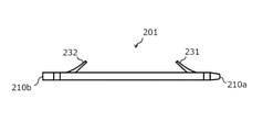
- the tube stent 201 made of a resin material has a distal end 210a and a proximal end 210b and extends in the longitudinal direction.
- the tube 201 has a distal flap 231 formed by making a notch in the outer surface on the distal side, and a proximal flap 232 formed by making a notch in the outer surface on the proximal side.
- a proximal flap 232 formed by making a notch in the outer surface on the proximal side There are (for example, Patent Documents 1 and 2).
- the proximal flap 232 and the distal flap 231 have the function of fixing the tube stent 201 in place in the in vivo lumen.
- the distal flap 231 is located distal to the stenosis (obstruction) of the bile duct and proximal to prevent the tube stent 201 from falling off the duodenum from the bile duct.
- the flap 232 is placed near the papilla of the duodenum outside the bile duct to prevent the tube stent 201 from entering the bile duct.
- the purpose of the tube stent is to perform bile drainage on the narrowed part of the bile duct.
- flaps prevent the tube stent from being displaced from a predetermined position in the bile duct.
- the effect of preventing the displacement due to the flap is not sufficient, and the current situation is that the tube stent is displaced.
- the tube stent disclosed in Patent Document 1 includes a magnetic element and a stopper member on the tube.
- the outer diameter of the stopper member is larger than the outer diameter of the portion from the end of the tube to the end of the stopper member, and the magnetic element and the stopper member protrude from the tube surface, so that it is difficult to deliver to the desired indwelling site. was there.
- the tube stent disclosed in Patent Document 2 has a plurality of grooves formed on the outer surface of the tube body along the longitudinal direction. These grooves ensure the flow of body fluids on the outside of the tube and are stochastically intended to be used longer than conventional ones. However, these grooves are not provided for the purpose of preventing the position of the narrowed portion in the living body from being displaced, and there is a problem that some means is required to prevent the position from being displaced after placement. there were.
- the present invention has been made in view of the above circumstances, and an object thereof is to prevent the tube stent from moving without making the outer diameter of the tube stent indwelling too large, and to prevent the tube stent from moving, and to prevent the tube stent from moving. It is an object of the present invention to provide a tube stent capable of facilitating passage through a lesion.
- the tube stent that was able to solve the above-mentioned problems is made of a resin material, has a distal end and a proximal end, and has a first part, a second part, and a third part in order from the distal end in the longitudinal direction.
- a tube having a portion having a first edge at the proximal end of the first portion and a second edge at the proximal end of the second portion, the thickness of the proximal end of the first portion being second. It is thicker than the wall thickness of the distal end of the part, the wall thickness of the second part is thicker from the distal end side to the proximal end side, and the wall thickness of the distal end of the third part is the thickness of the second part. It is thinner than the wall thickness at the proximal end.
- the tube stent of the present invention preferably has a plurality of second portions in the longitudinal direction. It is preferable that the first edge and the second edge are provided on the entire circumference of the outer surface of the tube.
- the difference between the maximum outer diameter and the minimum outer diameter of the tube is preferably 30% or less.
- the outer diameter of the proximal end of the first part or the outer diameter of the proximal end of the second part is the maximum outer diameter
- the outer diameter of the distal end of the first part or the outer diameter of the distal end of the second part is The minimum outer diameter is preferable.
- the outer diameter of any part of the third part is the maximum outer diameter
- the outer diameter of the distal end of the first part or the outer diameter of the distal end of the second part is the minimum outer diameter. ..
- the wall thickness of the proximal end of the first part is thicker than the wall thickness of the distal end of the second part, and the wall thickness of the second part is from the distal end side to the proximal end side.
- the wall thickness is thicker toward, and the wall thickness at the distal end of the third part is thinner than the wall thickness at the proximal end of the second part, so that the outer diameter of the tube stent placed in the living body is increased. It is possible to impart an edge that is caught in the narrowed portion without being too much. Therefore, it is possible to prevent the tube stent from moving after indwelling and to facilitate passage to a lesion such as a stenosis.
- the tube stent is used by attaching it to a delivery system (transport device) such as a catheter having a site where the tube stent is installed in order to transport the tube stent to the lesion.
- a delivery system transport device
- transport device such as a catheter having a site where the tube stent is installed in order to transport the tube stent to the lesion.
- the proximal end refers to the direction on the hand side of the user (operator) with respect to the extending direction of the tube stent, and the direction opposite to the distal end on the proximal side (that is, the direction toward the treatment target side). ). Further, the direction from the proximal end side to the distal end side of the tube stent is referred to as a longitudinal direction.
- the tube stent 1 of the present invention has a distal end 10a and a proximal end 10b, and the first part 21, the second part 22, and the third part 23 are in order from the distal end 10a. It is a tube having.
- the distal end 10a is the distal end of the delivery system and the proximal end 10b is located proximally. In the living body, the distal end 10a is arranged in the deep part of the body.
- the tube stent 1 is made of a resin material.
- the resin material include polyamide-based resin, polyester-based resin, polyurethane-based resin, polyolefin-based resin, fluororesin, vinyl chloride-based resin, silicone-based resin, and natural rubber. Only one of these may be used, or two or more thereof may be used in combination.
- a polyamide-based resin, a polyurethane-based resin, a polyolefin-based resin, and a fluorine-based resin are preferably used.
- the tube stent 1 has at least one of a polyamide-based resin, a polyurethane-based resin, a polyolefin-based resin, and a fluororesin, the biocompatibility and flexibility of the tube stent 1 can be achieved at the same time.
- the length of the tube stent 1 in the longitudinal direction is not particularly limited, but is preferably 3 cm or more and 18 cm or less. Of the total length of the tube stent 1 in the longitudinal direction, it is preferable that the first part 21 is 10 mm to 20 mm, the second part 22 is 1 mm to 5 mm, and the third part 23 is the rest. Although not shown, flaps may be provided in the first part 21 and the third part 23, and the length of the flaps is preferably 5 mm to 15 mm. A plurality of second parts 22 may be repeatedly provided. It is desirable that the length of the second part 22 is shorter than that of the first part 21 and the third part 23, because if the length is too long, kink is likely to occur.
- the first edge 11 is located at the proximal end of the first part 21, and the second edge 12 is located at the proximal end of the second part 22.
- the first edge 11 is an edge of the first part 21 formed by making the wall thickness of the proximal end of the first part 21 thicker than the wall thickness of the distal end of the second part 22.
- the second edge 12 is an edge of the second part 22 formed by making the wall thickness of the proximal end of the second part 22 thicker than the wall thickness of the distal end of the third part 23.
- the first edge 11 may be formed over the entire outer circumference of the tube stent 1, or may be formed on a part of the outer circumference of the tube stent 1.
- the total thickness of the proximal end of the first part 21 is thicker than the total thickness of the distal end of the second part 22. ..
- the meat at the proximal end of the first part 21 is formed.
- At least a portion of the thickness is thicker than at least a portion of the wall thickness at the distal end of Part 2.22. That is, part or all of the wall thickness at the proximal end of Part 1 21 is thicker than part or all of the wall thickness at the distal end of Part 2.
- the tube stent 1 by providing the tube stent 1 with a plurality of edges such as the first edge 11 and the second edge 12, these edges are effectively caught in the narrowed portion, and the tube stent 1 moves to cause misalignment. Can be prevented. Further, if the edge is caught in the lumen in the living body during the transportation of the tube stent 1, it becomes difficult to transport the tube stent 1 to the target site.
- the first edge 11 and the second edge 12 of the present invention are the tube stent 1. Since the wall thickness of the tube stent 1 is once thinned and then thickened at the edge portion, the first edge 11 and the second edge 12 are less likely to be caught in the lumen of the living body when the tube stent 1 is transported. ing.
- the wall thickness of the second part 22 becomes thicker from the distal end side to the proximal end side.
- the second edge 12 is formed by forming the protrusion into a tapered shape and providing the second edge 12 on the second portion 22, the second edge 12 is caught on the stenosis portion when the tube stent 1 is transported (when the stenosis is breached). It's getting harder.
- the wall thickness at the distal end of the third part 23 is thinner than the wall thickness at the proximal end of the second part 22. As a result, the second edge 12 is formed at the proximal end of the second part 22.
- the present invention by providing a plurality of edges on the main body of the tube stent 1, it is possible to prevent the tube stent 1 from moving with respect to the narrowed portion and shifting its position. If a protrusion or the like is directly applied to the tube stent body in order to prevent the position of the tube stent from being displaced as in the conventional case, the protrusion protrudes from the surface of the tube stent, and the outer diameter of the portion where the protrusion is provided becomes large. Therefore, the conventional tube stent has a problem that it is difficult to deliver to a desired indwelling site.
- the first edge 11 and the second edge 12 are provided so as to prevent the tube stent 1 from moving without increasing the outer diameter of the main body too much.
- Having a plurality of second edges 12 means that a plurality of tapered structures such as the second portion 22 are provided in the longitudinal axis direction. That is, by providing a plurality of the second portions 22, the number of the second edges 12 can be a plurality. Due to the plurality of second edges 12, when the tube stent 1 is placed at an arbitrary position, even if it is a lesion having a plurality of stenosis or a lesion such as a soft and slippery new intima. , The plurality of second edges 12 can prevent the tube stent 1 from moving.
- the first edge 11 and the second edge 12 may be provided on the entire circumference of the outer surface of the tube stent 1. Since the first edge 11 and the second edge 12 are located all around the outer surface of the tube stent 1, the tube stent 1 is located regardless of the position of the lesion in the radial direction of the in vivo lumen. The tube stent 1 can be prevented from moving by the first edge 11 and the second edge 12 present on the entire circumference of the outer surface of the tube.
- the first edge 11 and the second edge 12 may be provided on a part of the outer circumference of the tube stent 1. In this case, a plurality of first edges 11 and second edges 12 may be arranged so as to be arranged on the outer periphery of the tube stent 1 to form streaky first edges 11 and second edges 12 in the longitudinal direction.
- the first edge 11 and the first edge are the first.
- the two edges 12 are likely to be caught in the lesion, and the effect of preventing the tube stent 1 from moving is enhanced. It is desirable that the wall thickness difference between the first edge 11 and the distal end of the second part 22 and the wall thickness difference between the second edge 12 and the distal end of the third part 23 are large.
- the first edge 11 is formed by making the wall thickness of the proximal end of the first part 21 thicker than the wall thickness of the distal end of the second part 22.
- the second edge 12 has a tapered shape, so that when the tube stent 1 is transported (when the stenosis is breached), The second edge 12 is less likely to be caught in the narrowed portion.
- the wall thickness at the distal end of the third part 23 is thinner than the wall thickness at the proximal end of the second part 22 to form the second edge 12, and the distal ends of the second edge 12 and the third part 23.
- the difference between the maximum outer diameter and the minimum outer diameter of the tube stent 1 is 30% or less.
- the difference between the maximum outer diameter and the minimum outer diameter of the tube stent 1 is 30% or less, the difference in the outer diameter between the distal ends of the first edge 11 and the second part 22 and the difference between the second edge 12 and the third part 23
- the difference in outer diameter at the distal end of the tube stent 1 can be increased, and the effect of preventing the tube stent 1 from moving can be enhanced.
- the difference between the maximum outer diameter and the minimum outer diameter of the tube stent 1 is large, but if the outer diameter difference exceeds 30%, it is between the distal end of the first edge 11 and the second part 22, or the second edge.
- Kink is likely to occur between 12 and the distal end of Part 3 23, so 30% or less is desirable.
- the lower limit of the difference between the maximum outer diameter and the minimum outer diameter of the tube stent 1 is preferably 10% or more, more preferably 13% or more, and further preferably 15% or more.
- the outer diameter of the proximal end of the first part 21 or the outer diameter of the proximal end of the second part 22 is the maximum outer diameter, and the outer diameter of the distal end of the first part 21 or the distal end of the second part 22. It is preferable that the outer diameter of is the minimum outer diameter.
- the maximum outer diameter of the tube stent 1 is the outer diameter of the proximal end of the first part 21 or the outer diameter of the proximal end of the second part 22, and the minimum outer diameter of the tube stent 1 is the distal end of the first part 21.
- the outer diameter of the tube stent 1 or the outer diameter of the distal end of the second part 22 can be used to balance the overall rigidity of the tube stent 1.
- the outer diameter of any part of the third part 23 is the maximum outer diameter, and the outer diameter of the distal end of the first part 21 or the outer diameter of the distal end of the second part 22 is the minimum outer diameter. Is preferable.
- the maximum outer diameter of the tube stent 1 is the outer diameter of any part of the third part 23, and the minimum outer diameter of the tube stent 1 is the outer diameter of the distal end of the first part 21 or the distal of the second part 22. Due to the outer diameter of the end, the tube stent 1 having a well-balanced overall rigidity can be obtained.
- the edge of the tube stent 1 of the present invention can be formed by various methods.
- the outer surface of the tube can be tapered or edged by heating the tube and shaping it using a mold.
- the tube stent 1 of the present invention can be formed by connecting short tubes provided with a taper or an edge.
- a taper or edge can be provided by scraping or cutting the outer surface of the tube with a cutting tool. Since it is preferable that the outer surface and the inner surface of the edge portion of the tube stent 1 do not communicate with each other, it is preferable to process the tube stent 1 after passing a core material or the like through the lumen of the tube.
- Tube stent 10a Distal end 10b: Proximal end 11: First edge 12: Second edge 21: Part 1 22: Part 2 23: Part 3 201: Tube stent 210a: Distal end 210b: Proximal end 231: Distal flap 232: Proximal flap
Landscapes
- Health & Medical Sciences (AREA)
- Engineering & Computer Science (AREA)
- Biomedical Technology (AREA)
- Cardiology (AREA)
- Oral & Maxillofacial Surgery (AREA)
- Transplantation (AREA)
- Heart & Thoracic Surgery (AREA)
- Vascular Medicine (AREA)
- Life Sciences & Earth Sciences (AREA)
- Animal Behavior & Ethology (AREA)
- General Health & Medical Sciences (AREA)
- Public Health (AREA)
- Veterinary Medicine (AREA)
- Media Introduction/Drainage Providing Device (AREA)
Abstract
樹脂材料で形成され、遠位端(10a)と近位端(10b)とを有し、長手方向において遠位端(10a)から順に、第1部(21)、第2部(22)、第3部(23)を有するチューブであって、第1部(21)の近位端である第1エッジ(11)、第2部(22)の近位端である第2エッジ(12)を備え、第1部(21)の近位端の肉厚は、第2部(22)の遠位端の肉厚よりも厚く、第2部(22)の肉厚は、遠位端側から近位端側に向かって厚く、第3部(23)の遠位端の肉厚は、第2部(22)の近位端の肉厚よりも薄いチューブステント(1)。
Description
本発明は、フラップを有する生体内留置用のチューブステントに関するものである。
生体内留置チューブ等のチューブステント、特に、胆管用または膵管用のステントは、胆管や膵管等の生体内管腔が狭窄または閉塞することにより生じる胆道閉塞症、黄胆、胆道がん等の様々な疾患を治療するための医療器具である。チューブステントは、胆汁の胆管内から十二指腸側への排出や、狭窄または閉塞部位の病変部を内側から拡張することによる管腔内径の維持を目的として生体管腔に留置される。チューブステントの内腔にがん細胞等の病変部の組織が入り込んでチューブの内腔が閉塞または狭窄すると、チューブを交換する必要がある。
チューブステントは金属材料から構成されているものと、樹脂材料から構成されているものがある。上述のような治療において、樹脂材料から構成されている生体内留置チューブが使用されることがある。
まず、従来のチューブステントについて図2を用いて説明する。図2に示すように、樹脂材料から構成されているチューブステント201は、遠位端210aと近位端210bとを有し、長手方向に延在している。チューブ201は、遠位側の外表面に切り込みを入れることによって遠位フラップ231が形成され、近位側の外表面に切り込みを入れることによって近位フラップ232が形成されているものが一般的である(例えば、特許文献1~2)。近位フラップ232および遠位フラップ231は、チューブステント201を生体内管腔の所定の位置に固定する機能を有している。チューブステント201が胆管ステントである場合、例えば、遠位フラップ231は、胆管から十二指腸側にチューブステント201が脱落しないように胆管の狭窄部(閉塞部)よりも遠位側に配置され、近位フラップ232は、胆管内にチューブステント201が入り込まないように胆管外の十二指腸の乳頭付近に配置される。
チューブステントは胆管の狭窄部に対して、胆汁ドレナージを行うことが目的である。従来のチューブステントはフラップによって、チューブステントが胆管の所定の位置から位置ズレすることを防いでいる。しかし、フラップによる位置ズレを防止する効果は十分ではなく、チューブステントの位置ズレが生じているのが現状である。
特許文献1に開示されているチューブステントは、チューブ上に磁気要素やストッパ部材を含む。ストッパ部材の外径は、チューブの端部からストッパ部材の端部までの部分の外径よりも大きく、磁気要素やストッパ部材がチューブ表面から突出するため、所望の留置部位まで送達しにくいという問題があった。
特許文献2に開示されているチューブステントは、長手方向に沿ってチューブ本体の外側面に複数の溝が形成されている。これらの溝は、チューブ外側において体液の流れを確保し、確率的に従来のものよりも長時間使用することを目的としている。しかし、これらの溝は、生体内の狭窄部に対して、位置ズレ防止の目的で設けられたものではなく、留置後に位置がズレないようにするためには何らかの手段が必要になるという問題があった。
本発明は、前記事情に鑑みてなされたものであり、その目的は、生体内に留置されるチューブステントの外径を大きくさせすぎずにチューブステントが移動することを防止し、かつ狭窄部等の病変部への通過を円滑にすることができるチューブステントを提供することにある。
前記課題を解決することができたチューブステントは、樹脂材料で形成され、遠位端と近位端とを有し、長手方向において遠位端から順に、第1部、第2部、第3部を有するチューブであって、第1部の近位端にある第1エッジ、第2部の近位端にある第2エッジを備え、第1部の近位端の肉厚は、第2部の遠位端の肉厚よりも厚く、第2部の肉厚は、遠位端側から近位端側に向かって厚く、第3部の遠位端の肉厚は、第2部の近位端の肉厚よりも薄い。
本発明のチューブステントは、第2部が長手方向に複数あることが好ましい。第1エッジおよび第2エッジは、チューブの外表面の全周に備えられていることが好ましい。
また、本発明のチューブステントは、チューブの最大外径と最小外径の差が30%以下であることが好ましい。第1部の近位端の外径または第2部の近位端の外径が最大外径であり、第1部の遠位端の外径または第2部の遠位端の外径が最小外径であることが好ましい。あるいは、第3部のいずれかの箇所の外径が最大外径であり、第1部の遠位端の外径または第2部の遠位端の外径が最小外径であることが好ましい。
本発明のチューブステントは、第1部の近位端の肉厚は、第2部の遠位端の肉厚よりも厚く、第2部の肉厚は、遠位端側から近位端側に向かって肉厚が厚く、第3部の遠位端の肉厚は、第2部の近位端の肉厚よりも薄いことにより、生体内に留置されるチューブステントの外径を大きくさせすぎずに狭窄部へ引っかかるエッジを付与することができる。そのため、留置後のチューブステントが移動することを防止し、かつ狭窄部等の病変部への通過を円滑にすることができる。
以下、下記実施の形態に基づき本発明をより具体的に説明するが、本発明はもとより下記実施の形態によって制限を受けるものではなく、前・後記の趣旨に適合し得る範囲で適当に変更を加えて実施することも勿論可能であり、それらはいずれも本発明の技術的範囲に包含される。なお、各図面において、便宜上、ハッチングや部材符号等を省略する場合もあるが、かかる場合、明細書や他の図面を参照するものとする。また、図面における種々部材の寸法は、本発明の特徴の理解に資することを優先しているため、実際の寸法とは異なる場合がある。
チューブステントは、病変部までチューブステントを搬送するために、チューブステントを設置する部位を有するカテーテル等のデリバリーシステム(搬送装置)に取り付けて用いられる。
本発明において、近位端とはチューブステントの延在方向に対して使用者(術者)の手元側の方向を指し、遠位端とは近位側の反対方向(すなわち処置対象側の方向)を指す。また、チューブステントの近位端側から遠位端側への方向を長手方向と称する。
<チューブステントの全体構成>
本発明のチューブステント1は、図1に示すように、遠位端10aと近位端10bとを有し、遠位端10aから順に、第1部21、第2部22、第3部23を有するチューブである。遠位端10aは、デリバリーシステムの遠位側に配置される端部であり、近位端10bは、近位側に配置される。生体内において、遠位端10aが体深部に配置される。
本発明のチューブステント1は、図1に示すように、遠位端10aと近位端10bとを有し、遠位端10aから順に、第1部21、第2部22、第3部23を有するチューブである。遠位端10aは、デリバリーシステムの遠位側に配置される端部であり、近位端10bは、近位側に配置される。生体内において、遠位端10aが体深部に配置される。
チューブステント1は樹脂材料で形成される。樹脂材料としては、ポリアミド系樹脂、ポリエステル系樹脂、ポリウレタン系樹脂、ポリオレフィン系樹脂、フッ素系樹脂、塩化ビニル系樹脂、シリコーン系樹脂、天然ゴム等が挙げられる。これらは1種のみを用いてもよく、2種以上を併用してもよい。チューブステント1を形成する樹脂材料として、中でも、ポリアミド系樹脂、ポリウレタン系樹脂、ポリオレフィン系樹脂、フッ素系樹脂が好適に用いられる。チューブステント1がポリアミド系樹脂、ポリウレタン系樹脂、ポリオレフィン系樹脂、およびフッ素系樹脂の少なくとも1つを有していることにより、チューブステント1の生体適合性と柔軟性を両立することができる。
チューブステント1の長手方向の長さは、特に限定されないが、3cm以上18cm以下であることが好ましい。チューブステント1の長手方向の全長のうち、第1部21は10mm~20mm、第2部22は1mm~5mm、第3部23はその残部であることが好ましい。図示していないが、第1部21および第3部23にフラップが設けられていてもよく、フラップの長さは5mm~15mmが好ましい。第2部22は複数繰り返し設けられていてもよい。第2部22は、長すぎるとキンクが生じやすくなるため、第1部21および第3部23よりも短い長さであることが望ましい。
第1エッジ11は、第1部21の近位端に位置し、第2エッジ12は、第2部22の近位端に位置する。第1エッジ11は、第1部21の近位端の肉厚を第2部22の遠位端の肉厚よりも厚くすることにより形成される、第1部21のエッジである。第2エッジ12は、第2部22の近位端の肉厚を第3部23の遠位端の肉厚よりも厚くすることにより形成される、第2部22のエッジである。第1エッジ11は、チューブステント1の外周の全体にわたって形成されていてもよく、チューブステント1の外周の一部に形成されていてもよい。第1エッジ11がチューブステント1の外周全体にわたって形成されている場合、第1部21の近位端の肉厚の全部は、第2部22の遠位端の肉厚の全部よりも厚くなる。第1エッジ11がチューブステント1の外周全体にわたって形成されていない場合、つまり、第1エッジ11がチューブステント1の外周の一部に形成されている場合、第1部21の近位端の肉厚の少なくとも一部は、第2部22の遠位端の肉厚の少なくとも一部よりも厚くなる。すなわち、第1部21の近位端の肉厚の一部または全部は、第2部22の遠位端の肉厚の一部または全部よりも厚い。第2エッジ12の場合も同様であって、第2部22の近位端の肉厚の一部または全部は、第3部23の遠位端の肉厚の一部または全部よりも厚い。換言すると、第3部23の遠位端の肉厚は、第2部22の近位端の肉厚よりも薄い。
本発明では、チューブステント1に第1エッジ11および第2エッジ12といった複数のエッジを設けることによって、これらのエッジが効果的に狭窄部に引っかかり、チューブステント1が移動して位置ズレが生じることを防止することができる。また、チューブステント1の搬送時にエッジが生体内管腔に引っかかると、目的部位にチューブステント1を搬送することが難しくなるが、本発明の第1エッジ11および第2エッジ12は、チューブステント1の肉厚がいったん薄くなった上で、エッジ部で肉厚を厚くする形状であるため、チューブステント1の搬送時には第1エッジ11および第2エッジ12が生体内管腔に引っかかりにくい形状となっている。
第2部22の肉厚は、遠位端側から近位端側に向かって肉厚が厚くなる。突起をテーパ形状にして第2エッジ12を形成し、第2部22に第2エッジ12を設けることにより、チューブステント1の搬送時(狭窄突破時)に、第2エッジ12が狭窄部に引っかかりにくくなっている。なお、第3部23の遠位端の肉厚は、第2部22の近位端の肉厚よりも薄い。これにより、第2部22の近位端に第2エッジ12が形成される。
本発明では、チューブステント1の本体部に複数のエッジを設けることによって、狭窄部に対してチューブステント1が移動し、位置がずれてしまうことを防止することができる。従来のように、チューブステントの位置ズレを防ぐため、チューブステント本体に突起等を直接付与すると、チューブステントの表面から突起が突出し、突起が設けられている部分の外径が大きくなってしまう。そのため、従来のチューブステントは、所望の留置部位まで送達しにくいという問題があった。一方、本発明では、第1エッジ11および第2エッジ12を備えることにより、チューブステント1本体の外径を大きくさせ過ぎずに移動を防止する構造となっている。
第2エッジ12は、複数あることが好ましい。第2エッジ12が複数あるとは、第2部22のようなテーパ構造が長手軸方向に複数設けられる構造である。つまり、第2部22を複数設けることにより、第2エッジ12を複数にすることができる。第2エッジ12が複数あることにより、チューブステント1を任意の位置へ留置した際に、狭窄部が複数ある病変部や、柔らかくて表面が滑りやすい新生内膜等の病変部であったとしても、複数の第2エッジ12によってチューブステント1が移動するのを防止することできる。
第1エッジ11および第2エッジ12はチューブステント1の外表面の全周に備えられていてもよい。第1エッジ11および第2エッジ12がチューブステント1の外表面の全周にあることにより、病変部の位置が生体内管腔の径方向においてどのような位置であったとしても、チューブステント1の外表面の全周に存在している第1エッジ11および第2エッジ12によってチューブステント1が移動することを防止することができる。なお、第1エッジ11および第2エッジ12は、チューブステント1の外周上の一部に設けられてもよい。この場合、チューブステント1の外周上に第1エッジ11および第2エッジ12を複数並べるように配置し、長手方向に筋状の第1エッジ11および第2エッジ12としてもよい。
第1エッジ11と第2部22の遠位端との肉厚差、また、第2エッジ12と第3部23の遠位端との肉厚差を設けることにより、第1エッジ11および第2エッジ12が病変部に引っかかりやすくなり、チューブステント1が移動することを防止する効果を高める。なお、第1エッジ11と第2部22の遠位端との肉厚差、および第2エッジ12と第3部23の遠位端との肉厚差は大きいことが望ましい。
第1部21の近位端の肉厚を第2部22の遠位端の肉厚よりも厚くすることによって、第1エッジ11を形成する。第2部22の肉厚を遠位端側から近位端側に向かって厚くすることによって、第2エッジ12をテーパ形状としていることにより、チューブステント1の搬送時(狭窄突破時)に、第2エッジ12が狭窄部に引っかかりにくくなる。第3部23の遠位端の肉厚は、第2部22の近位端の肉厚よりも薄くすることで第2エッジ12を形成し、第2エッジ12と第3部23の遠位端との外径差を大きくすることによって、チューブステント1が移動することを防止する効果を高める。
チューブステント1の最大外径と最小外径の差が30%以下であることが望ましい。チューブステント1の最大外径と最小外径の差が30%以下であることにより、第1エッジ11と第2部22の遠位端の外径差や、第2エッジ12と第3部23の遠位端の外径差を大きくすることができ、チューブステント1が移動することを防止する効果を高めることができる。チューブステント1の最大外径と最小外径の差は大きいことが望ましいが、外径差が30%を超える場合、第1エッジ11と第2部22の遠位端の間、または第2エッジ12と第3部23の遠位端の間でキンクが生じやすくなるため、30%以下であることが望ましい。なお、チューブステント1の最大外径と最小外径の差の下限値は、10%以上であることが好ましく、13%以上であることがより好ましく、15%以上であることがさらに好ましい。
第1部21の近位端の外径または第2部22の近位端の外径が最大外径であり、第1部21の遠位端の外径または第2部22の遠位端の外径が最小外径であることが好ましい。チューブステント1の最大外径が第1部21の近位端の外径または第2部22の近位端の外径であり、チューブステント1の最小外径が第1部21の遠位端の外径または第2部22の遠位端の外径であることにより、チューブステント1の全体の剛性のバランスをとることができる。
また、第3部23のいずれかの箇所の外径が最大外径であり、第1部21の遠位端の外径または第2部22の遠位端の外径が最小外径であることが好ましい。チューブステント1の最大外径が第3部23のいずれかの箇所の外径であり、チューブステント1の最小外径が第1部21の遠位端の外径または第2部22の遠位端の外径であることにより、全体の剛性のバランスがとれたチューブステント1とすることができる。
<チューブステントの製造方法>
本発明のチューブステント1のエッジは、種々の方法により形成することができる。チューブに熱可塑性樹脂を用いた場合、チューブを加熱し、型を用いて形状づけることによって、チューブの外表面にテーパやエッジを設けることができる。また、テーパやエッジを設けた短いチューブをつなぎ合わせて本発明のチューブステント1を形成することもできる。
本発明のチューブステント1のエッジは、種々の方法により形成することができる。チューブに熱可塑性樹脂を用いた場合、チューブを加熱し、型を用いて形状づけることによって、チューブの外表面にテーパやエッジを設けることができる。また、テーパやエッジを設けた短いチューブをつなぎ合わせて本発明のチューブステント1を形成することもできる。
あるいは、チューブの外表面を刃物で削る、切除すること等により、テーパやエッジを設けることができる。チューブステント1のエッジ部分は外表面と内表面とが連通しないことが好ましいため、チューブの内腔に芯材等を通した後に加工することが好ましい。
本願は、2020年8月28日に出願された日本国特許出願第2020-144582号に基づく優先権の利益を主張するものである。2020年8月28日に出願された日本国特許出願第2020-144582号の明細書の全内容が、本願に参考のため援用される。
1:チューブステント
10a:遠位端
10b:近位端
11:第1エッジ
12:第2エッジ
21:第1部
22:第2部
23:第3部
201:チューブステント
210a:遠位端
210b:近位端
231:遠位フラップ
232:近位フラップ
10a:遠位端
10b:近位端
11:第1エッジ
12:第2エッジ
21:第1部
22:第2部
23:第3部
201:チューブステント
210a:遠位端
210b:近位端
231:遠位フラップ
232:近位フラップ
Claims (6)
- 樹脂材料で形成され、遠位端と近位端とを有し、長手方向において前記遠位端から順に、第1部、第2部、第3部を有するチューブであって、前記第1部の近位端にある第1エッジ、前記第2部の近位端にある第2エッジを備え、
前記第1部の近位端の肉厚は、前記第2部の遠位端の肉厚よりも厚く、
前記第2部の肉厚は、遠位端側から近位端側に向かって厚く、
前記第3部の遠位端の肉厚は、前記第2部の近位端の肉厚よりも薄いチューブステント。 - 前記第2部が長手方向に複数ある請求項1に記載のチューブステント。
- 前記第1エッジおよび前記第2エッジは、チューブの外表面の全周に備えられている請求項1または2に記載のチューブステント。
- 前記チューブの最大外径と最小外径の差が30%以下である請求項1~3のいずれか一項に記載のチューブステント。
- 前記第1部の近位端の外径または前記第2部の近位端の外径が最大外径であり、前記第1部の遠位端の外径または第2部の遠位端の外径が最小外径である請求項1~4のいずれか一項に記載のチューブステント。
- 前記第3部のいずれかの箇所の外径が最大外径であり、前記第1部の遠位端の外径または第2部の遠位端の外径が最小外径である請求項1~4のいずれか一項に記載のチューブステント。
Priority Applications (1)
| Application Number | Priority Date | Filing Date | Title |
|---|---|---|---|
| JP2022545462A JP7651582B2 (ja) | 2020-08-28 | 2021-06-14 | チューブステント |
Applications Claiming Priority (2)
| Application Number | Priority Date | Filing Date | Title |
|---|---|---|---|
| JP2020-144582 | 2020-08-28 | ||
| JP2020144582 | 2020-08-28 |
Publications (1)
| Publication Number | Publication Date |
|---|---|
| WO2022044488A1 true WO2022044488A1 (ja) | 2022-03-03 |
Family
ID=80353059
Family Applications (1)
| Application Number | Title | Priority Date | Filing Date |
|---|---|---|---|
| PCT/JP2021/022447 Ceased WO2022044488A1 (ja) | 2020-08-28 | 2021-06-14 | チューブステント |
Country Status (2)
| Country | Link |
|---|---|
| JP (1) | JP7651582B2 (ja) |
| WO (1) | WO2022044488A1 (ja) |
Citations (5)
| Publication number | Priority date | Publication date | Assignee | Title |
|---|---|---|---|---|
| JP2000316979A (ja) * | 1999-05-10 | 2000-11-21 | Fuji Systems Kk | ステント |
| US20100100170A1 (en) * | 2008-10-22 | 2010-04-22 | Boston Scientific Scimed, Inc. | Shape memory tubular stent with grooves |
| US20170014247A1 (en) * | 2015-07-15 | 2017-01-19 | Cook Medical Technologies Llc | Stent Anti-Migration Mechanism |
| WO2018230435A1 (ja) * | 2017-06-13 | 2018-12-20 | 株式会社カネカ | 生体内留置チューブ |
| JP2020072872A (ja) * | 2012-04-06 | 2020-05-14 | ボストン サイエンティフィック サイムド,インコーポレイテッドBoston Scientific Scimed,Inc. | 内部人工器官 |
-
2021
- 2021-06-14 JP JP2022545462A patent/JP7651582B2/ja active Active
- 2021-06-14 WO PCT/JP2021/022447 patent/WO2022044488A1/ja not_active Ceased
Patent Citations (5)
| Publication number | Priority date | Publication date | Assignee | Title |
|---|---|---|---|---|
| JP2000316979A (ja) * | 1999-05-10 | 2000-11-21 | Fuji Systems Kk | ステント |
| US20100100170A1 (en) * | 2008-10-22 | 2010-04-22 | Boston Scientific Scimed, Inc. | Shape memory tubular stent with grooves |
| JP2020072872A (ja) * | 2012-04-06 | 2020-05-14 | ボストン サイエンティフィック サイムド,インコーポレイテッドBoston Scientific Scimed,Inc. | 内部人工器官 |
| US20170014247A1 (en) * | 2015-07-15 | 2017-01-19 | Cook Medical Technologies Llc | Stent Anti-Migration Mechanism |
| WO2018230435A1 (ja) * | 2017-06-13 | 2018-12-20 | 株式会社カネカ | 生体内留置チューブ |
Also Published As
| Publication number | Publication date |
|---|---|
| JP7651582B2 (ja) | 2025-03-26 |
| JPWO2022044488A1 (ja) | 2022-03-03 |
Similar Documents
| Publication | Publication Date | Title |
|---|---|---|
| US11766542B2 (en) | Catheter | |
| US20170028170A1 (en) | Guide catheter extension device and methods of use for cardiology procedures | |
| CA2695963A1 (en) | Deployment system for soft stents | |
| WO2018054275A1 (zh) | 一种可扩导管鞘和介入器械输送装置 | |
| EP3811899B1 (en) | Stent for bypass between hollow organs and stent delivery system including stent for bypass between hollow organs | |
| JP2024141523A (ja) | 医療用長尺体 | |
| JP6415541B2 (ja) | ステントデリバリーシステム及び内視鏡システム | |
| JP6125633B2 (ja) | ずれ防止胆管ステント | |
| CN112714659B (zh) | 医疗用管状体运送装置 | |
| JP7410990B2 (ja) | 生体内留置チューブ | |
| JP7378459B2 (ja) | 医療用管状体搬送装置およびその製造方法 | |
| JP7378460B2 (ja) | 医療用管状体搬送装置およびその製造方法 | |
| WO2022044488A1 (ja) | チューブステント | |
| WO2024043219A1 (ja) | ステントキット、ステントキットを有するステントシステム、およびステントキットの製造方法 | |
| JP2011255001A (ja) | カテーテル補助具およびカテーテルユニット | |
| JP6633513B2 (ja) | カテーテル及びカテーテルセット | |
| JP7849983B2 (ja) | 胆管用チューブステント | |
| CN113556992A (zh) | 医疗用管状体输送装置 | |
| JP7329042B2 (ja) | 医療用管状体搬送装置 | |
| WO2022209351A1 (ja) | 医療用管状体搬送装置およびその製造方法 | |
| WO2024172101A1 (ja) | 医療用具 | |
| WO2025074843A1 (ja) | 医療用具 | |
| JP2018201575A (ja) | カテーテルおよびその製造方法 | |
| WO2025150326A1 (ja) | 医療用具 | |
| WO2025177936A1 (ja) | 生体内留置具 |
Legal Events
| Date | Code | Title | Description |
|---|---|---|---|
| 121 | Ep: the epo has been informed by wipo that ep was designated in this application |
Ref document number: 21860919 Country of ref document: EP Kind code of ref document: A1 |
|
| ENP | Entry into the national phase |
Ref document number: 2022545462 Country of ref document: JP Kind code of ref document: A |
|
| NENP | Non-entry into the national phase |
Ref country code: DE |
|
| 122 | Ep: pct application non-entry in european phase |
Ref document number: 21860919 Country of ref document: EP Kind code of ref document: A1 |