WO2022044317A1 - 測距装置 - Google Patents
測距装置 Download PDFInfo
- Publication number
- WO2022044317A1 WO2022044317A1 PCT/JP2020/032857 JP2020032857W WO2022044317A1 WO 2022044317 A1 WO2022044317 A1 WO 2022044317A1 JP 2020032857 W JP2020032857 W JP 2020032857W WO 2022044317 A1 WO2022044317 A1 WO 2022044317A1
- Authority
- WO
- WIPO (PCT)
- Prior art keywords
- light
- optical
- light receiving
- optical system
- scanning
- Prior art date
- Legal status (The legal status is an assumption and is not a legal conclusion. Google has not performed a legal analysis and makes no representation as to the accuracy of the status listed.)
- Ceased
Links
Images







Classifications
-
- G—PHYSICS
- G02—OPTICS
- G02B—OPTICAL ELEMENTS, SYSTEMS OR APPARATUS
- G02B26/00—Optical devices or arrangements for the control of light using movable or deformable optical elements
- G02B26/08—Optical devices or arrangements for the control of light using movable or deformable optical elements for controlling the direction of light
- G02B26/10—Scanning systems
- G02B26/101—Scanning systems with both horizontal and vertical deflecting means, e.g. raster or XY scanners
-
- G—PHYSICS
- G01—MEASURING; TESTING
- G01S—RADIO DIRECTION-FINDING; RADIO NAVIGATION; DETERMINING DISTANCE OR VELOCITY BY USE OF RADIO WAVES; LOCATING OR PRESENCE-DETECTING BY USE OF THE REFLECTION OR RERADIATION OF RADIO WAVES; ANALOGOUS ARRANGEMENTS USING OTHER WAVES
- G01S17/00—Systems using the reflection or reradiation of electromagnetic waves other than radio waves, e.g. lidar systems
- G01S17/02—Systems using the reflection of electromagnetic waves other than radio waves
- G01S17/06—Systems determining position data of a target
- G01S17/08—Systems determining position data of a target for measuring distance only
- G01S17/10—Systems determining position data of a target for measuring distance only using transmission of interrupted, pulse-modulated waves
-
- G—PHYSICS
- G01—MEASURING; TESTING
- G01S—RADIO DIRECTION-FINDING; RADIO NAVIGATION; DETERMINING DISTANCE OR VELOCITY BY USE OF RADIO WAVES; LOCATING OR PRESENCE-DETECTING BY USE OF THE REFLECTION OR RERADIATION OF RADIO WAVES; ANALOGOUS ARRANGEMENTS USING OTHER WAVES
- G01S7/00—Details of systems according to groups G01S13/00, G01S15/00, G01S17/00
- G01S7/48—Details of systems according to groups G01S13/00, G01S15/00, G01S17/00 of systems according to group G01S17/00
- G01S7/481—Constructional features, e.g. arrangements of optical elements
- G01S7/4811—Constructional features, e.g. arrangements of optical elements common to transmitter and receiver
- G01S7/4812—Constructional features, e.g. arrangements of optical elements common to transmitter and receiver transmitted and received beams following a coaxial path
-
- G—PHYSICS
- G01—MEASURING; TESTING
- G01S—RADIO DIRECTION-FINDING; RADIO NAVIGATION; DETERMINING DISTANCE OR VELOCITY BY USE OF RADIO WAVES; LOCATING OR PRESENCE-DETECTING BY USE OF THE REFLECTION OR RERADIATION OF RADIO WAVES; ANALOGOUS ARRANGEMENTS USING OTHER WAVES
- G01S7/00—Details of systems according to groups G01S13/00, G01S15/00, G01S17/00
- G01S7/48—Details of systems according to groups G01S13/00, G01S15/00, G01S17/00 of systems according to group G01S17/00
- G01S7/481—Constructional features, e.g. arrangements of optical elements
- G01S7/4816—Constructional features, e.g. arrangements of optical elements of receivers alone
-
- G—PHYSICS
- G01—MEASURING; TESTING
- G01S—RADIO DIRECTION-FINDING; RADIO NAVIGATION; DETERMINING DISTANCE OR VELOCITY BY USE OF RADIO WAVES; LOCATING OR PRESENCE-DETECTING BY USE OF THE REFLECTION OR RERADIATION OF RADIO WAVES; ANALOGOUS ARRANGEMENTS USING OTHER WAVES
- G01S7/00—Details of systems according to groups G01S13/00, G01S15/00, G01S17/00
- G01S7/48—Details of systems according to groups G01S13/00, G01S15/00, G01S17/00 of systems according to group G01S17/00
- G01S7/481—Constructional features, e.g. arrangements of optical elements
- G01S7/4817—Constructional features, e.g. arrangements of optical elements relating to scanning
-
- G—PHYSICS
- G02—OPTICS
- G02B—OPTICAL ELEMENTS, SYSTEMS OR APPARATUS
- G02B26/00—Optical devices or arrangements for the control of light using movable or deformable optical elements
- G02B26/08—Optical devices or arrangements for the control of light using movable or deformable optical elements for controlling the direction of light
- G02B26/0816—Optical devices or arrangements for the control of light using movable or deformable optical elements for controlling the direction of light by means of one or more reflecting elements
- G02B26/0833—Optical devices or arrangements for the control of light using movable or deformable optical elements for controlling the direction of light by means of one or more reflecting elements the reflecting element being a micromechanical device, e.g. a MEMS mirror, DMD
Definitions
- This disclosure relates to a distance measuring device.
- Patent Document 1 discloses an object detection device including a light projecting unit, a scanning unit, and a light receiving unit.
- the light projecting unit includes a laser diode module and a light projecting optical system.
- the scanning unit includes a mirror and an actuator for driving the mirror.
- the light receiving unit includes a condenser lens, a light receiving element, and an aperture.
- the divergence angle ⁇ of the laser beam emitted from the laser diode module is not more than or equal to the angle ⁇ .
- the angle ⁇ is given by arctan (D / d). D represents the diameter of the aperture, and d represents the distance from the condenser lens to the aperture.
- the distance measuring device includes a first light source, a scanning mirror, and a first light receiving optical system.
- the first light source emits a first light beam.
- the scanning mirror scans the first light beam.
- the first light receiving optical system receives the first return light generated by the reflection or scattering of the first light beam by at least one object.
- the first light receiving optical system includes a first condensing optical system, a first light receiving element, and a first aperture between the first condensing optical system and the first light receiving element.
- the first aperture is arranged on the first focal plane of the first condensing optical system.
- the first viewing angle of the first light receiving optical system is smaller than the first divergence angle of the first light beam.
- the first viewing angle is given by arctan (D 1 / f 1 ).
- f 1 represents the first focal length of the first condensing optical system
- D 1 represents the first diameter of the first hole provided in the first aperture.
- the ranging device of the second aspect of the present disclosure includes a plurality of light sources, a scanning mirror, an optical scanning area correction optical member, and a plurality of light receiving optical systems.
- the plurality of light sources emit a plurality of light beams, respectively.
- the scanning mirror scans a plurality of light beams.
- the optical scanning region correction optical member corrects at least one of a plurality of optical scanning regions formed by a plurality of light beams scanned by a scanning mirror.
- the plurality of light receiving optical systems each receive a plurality of return lights generated by reflecting or scattering the plurality of light beams by at least one object.
- Each of the plurality of light receiving optical systems includes a condensing optical system, a light receiving element, and an aperture between the condensing optical system and the light receiving element.
- the aperture is located on the focal plane of the condensing optical system.
- the viewing angle of the light-receiving optical system is smaller than the divergence angle of each of the plurality of light beams corresponding to the light-receiving optical system.
- the viewing angle of the light receiving optical system is given by arctan (D / f).
- f represents the focal length of the condensing optical system.
- D represents the diameter of the hole provided in the aperture.
- One first end of a pair of light scan regions adjacent to each other of a plurality of light scan regions overlaps only with the other second end of the pair of light scan regions or the other second end of the pair of light scan regions.
- the first axis is the direction in which the optical scanning region is expanded by being in contact with the portion.
- the normal line of the scanning mirror when the scanning mirror is in the center of the rotation range of the scanning mirror corresponding to a plurality of optical scanning regions is defined as the second axis.
- the diameter of the hole provided in the aperture is large.
- the distance measuring device includes a plurality of light sources, a scanning mirror, an optical scanning area correction optical member, and a plurality of light receiving optical systems.
- the plurality of light sources emit a plurality of light beams, respectively.
- the scanning mirror scans a plurality of light beams.
- the optical scanning region correction optical member corrects at least one of a plurality of optical scanning regions formed by a plurality of light beams scanned by a scanning mirror.
- the plurality of light receiving optical systems each receive a plurality of return lights generated by reflecting or scattering the plurality of light beams by at least one object.
- Each of the plurality of light receiving optical systems includes a condensing optical system, a light receiving element, and an aperture between the condensing optical system and the light receiving element.
- the aperture is located on the focal plane of the condensing optical system.
- the viewing angle of the light-receiving optical system is smaller than the divergence angle of each of the plurality of light beams corresponding to the light-receiving optical system.
- the viewing angle of the light receiving optical system is given by arctan (D / f).
- f represents the focal length of the condensing optical system.
- D represents the diameter of the hole provided in the aperture.
- One first end of a pair of light scan regions adjacent to each other of a plurality of light scan regions overlaps only with the other second end of the pair of light scan regions or the other second end of the pair of light scan regions.
- the first axis is the direction in which the optical scanning region is expanded by being in contact with the portion.
- the normal line of the scanning mirror when the scanning mirror is in the center of the rotation range of the scanning mirror corresponding to a plurality of optical scanning regions is defined as the second axis.
- the diameter of the hole provided in the aperture is small.
- the first aperture makes the first viewing angle of the first light receiving optical system smaller than the first divergence angle of the first light beam, and is incident on the first light receiving element. Limits the angular range of the first return light that can be. Therefore, the resolution of the ranging device according to the first aspect of the present disclosure can be improved.
- the aperture makes the viewing angle of the light receiving optical system smaller than the divergence angle of each of the plurality of light beams corresponding to the light receiving optical system, and the light receiving element Limits the angular range of return light that can be incident on. Therefore, the resolution of the distance measuring device in the second aspect and the third aspect of the present disclosure can be improved.
- FIG. 3 is a schematic enlarged view of an irradiation optical system and a light source included in the distance measuring device according to the first to third embodiments. It is a schematic enlarged view of the 1st light receiving optical system included in the distance measuring apparatus of Embodiment 1 and Embodiment 3. It is a schematic enlarged view of the 1st light receiving optical system included in the distance measuring apparatus of the 1st modification of Embodiment 1.
- FIG. It is a schematic diagram of the light beam scanning apparatus included in the ranging apparatus of the 2nd modification of Embodiment 1.
- FIG. 2 It is a schematic diagram of the light beam scanning apparatus included in the ranging apparatus of Embodiment 2.
- FIG. It is a schematic enlarged view of the 1st light receiving optical system included in the distance measuring apparatus of Embodiment 2.
- FIG. It is a schematic plan view of the light beam scanning apparatus included in the ranging apparatus of Embodiment 3.
- FIG. It is a schematic front view of the light beam scanning apparatus included in the ranging apparatus of Embodiment 3.
- FIG. It is a schematic enlarged view of the 2nd light receiving optical system included in the distance measuring apparatus of Embodiment 3.
- FIG. It is a figure which shows the definition of ⁇ xa and ⁇ ya .
- It is a figure which shows the plurality of optical scanning areas of the distance measuring device of a comparative example.
- It is a figure which shows the plurality of optical scanning regions of the distance measuring apparatus of Embodiment 3.
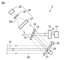
- the distance measuring device 1 of the first embodiment will be described with reference to FIGS. 1 to 4.
- the distance measuring device 1 includes a light beam scanning device 2, a computer 3, and a housing 7.
- the light beam scanning device 2 includes a light source 10, an irradiation optical system 15, a light beam splitter 16, a scanning mirror 20, and a light receiving optical system 30.
- the light source 10 emits a light beam 12.
- the light source 10 is a semiconductor laser and the light beam 12 is a laser beam.
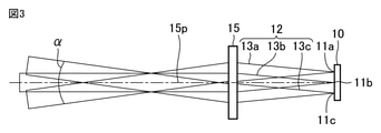
- the light source 10 includes, for example, a plurality of light emitting points 11a, 11b, 11c as shown in FIG.
- the light source 10 has, for example, a high output of 10 W or more.
- the plurality of light emitting points 11a, 11b, 11c are arranged in one direction such as the horizontal direction.
- the light source 10 has a light emitting region width so wide that it cannot be regarded as a point light source in the direction in which a plurality of light emitting points 11a, 11b, and 11c are arranged.
- the plurality of light emitting points 11a, 11b, 11c emit a plurality of light beams 13a, 13b, 13c, respectively.
- the light beam 12 includes a plurality of light beams 13a, 13b, 13c.
- the optical axes of the plurality of light beams 13a, 13b, and 13c are parallel to each other.
- the optical axes of the plurality of light beams 13a, 13b, and 13c are, for example, parallel to the optical axis 15p of the irradiation optical system 15.
- Each of the plurality of light beams 13a, 13b, and 13c has a spreading angle.
- the irradiation optical system 15 collimates the light beam 12 emitted from the light source 10.
- the irradiation optical system 15 includes, for example, a convex lens.
- the plurality of light emitting points 11a, 11b, and 11c are located on the focal plane of the irradiation optical system 15.
- the light source 10 has a light emitting region width so wide that it cannot be regarded as a point light source in the direction in which the plurality of light emitting points 11a, 11b, 11c are arranged. Therefore, as shown in FIG. 3, the light beam 12 that has passed through the irradiation optical system 15 has a divergence angle ⁇ in the direction in which the plurality of light emitting points 11a, 11b, and 11c are arranged.
- one of the plurality of light emitting points 11a, 11b, 11c is located on the optical axis 15p of the irradiation optical system 15 (that is, at the focal point of the irradiation optical system 15). Therefore, the light beam 13b emitted from the light emitting point 11b is collimated by the irradiation optical system 15 and travels parallel to the optical axis 15p of the irradiation optical system 15.
- the light emitting points 11a and 11c are deviated from the optical axis 15p of the irradiation optical system 15 (that is, the focal point of the irradiation optical system 15) in the direction in which the plurality of light emitting points 11a, 11b and 11c are arranged. .. Therefore, the light beam 13a emitted from the light emitting point 11a is collimated by the irradiation optical system 15 and travels diagonally with respect to the optical axis 15p of the irradiation optical system 15.
- the light beam 13c emitted from the light emitting point 11c is collimated by the irradiation optical system 15 and travels diagonally with respect to the optical axis 15p of the irradiation optical system 15.
- the light beam 12 that has passed through the irradiation optical system 15 has a divergence angle ⁇ .
- the light beam splitter 16 includes a light beam 12 and a return light 26 produced by the light beam 12 being reflected or scattered by at least one object 9 (see FIG. 1).
- the light beam splitter 16 reflects the light beam 12 and transmits the return light 26.
- the light beam splitter 16 includes a reflecting unit 17 and a transmitting unit 18.
- the reflecting unit 17 reflects the light beam 12 that has passed through the irradiation optical system 15 toward the scanning mirror 20.
- the transmission unit 18 transmits the return light 26 toward the light receiving optical system 30.
- the light beam splitter 16 is obtained, for example, by selectively forming a reflective film on a portion of the transparent plate corresponding to the reflective portion 17.
- the scanning mirror 20 reflects and scans the light beam 12.
- the scanning mirror 20 may rotate around two axes of rotation 21 and 22 that are parallel to the plane perpendicular to the normal of the scanning mirror 20 and perpendicular to each other.
- the scanning mirror 20 scans the light beam 12 two-dimensionally.
- the scanning mirror 20 is, for example, a microelectromechanical system (MEMS) mirror.
- MEMS microelectromechanical system
- the light receiving optical system 30 receives the return light 26.
- the light receiving optical system 30 includes a condensing optical system 31, an aperture 32, and a light receiving element 36.
- the condensing optical system 31 guides the return light 26 to the light receiving element 36 while condensing the light.
- the condensing optical system 31 includes, for example, a condensing lens.
- the condensing optical system 31 has a first focal length f 1 .
- the light receiving element 36 receives the return light 26.
- the light receiving element 36 is, for example, a photodiode such as an avalanche photodiode or a single photon avalanche photodiode, or a silicon photomultiplier (SiPM).
- a photodiode such as an avalanche photodiode or a single photon avalanche photodiode, or a silicon photomultiplier.
- SiPM silicon photomultiplier
- the light receiving element 36 includes a light receiving region 37.
- the light receiving region 37 is a region of the light receiving element 36 that has sensitivity to the return light 26.
- the return light 26 is incident on the light receiving region 37.
- the light receiving region 37 has a diameter D r1 in the direction corresponding to the divergence angle ⁇ .
- the light receiving region 37 of the light receiving element 36 is separated from the condensing optical system 31 by a distance d 1 in the optical axis direction of the return light 26.
- the aperture 32 is arranged between the condensing optical system 31 and the light receiving element 36.
- the aperture 32 is arranged on the focal plane of the condensing optical system 31.
- the aperture 32 is provided with a hole 32h.
- the aperture 32 limits the angular range of the return light 26 that can be incident on the light receiving element 36. Since the light receiving optical system 30 includes the aperture 32, the first viewing angle ⁇ 1 of the light receiving optical system 30 is given by arctan (D 1 / f 1 ). D 1 is the diameter of the hole 32h in the direction corresponding to the divergence angle ⁇ .
- the first viewing angle ⁇ 1 of the light receiving optical system 30 is smaller than the divergence angle ⁇ of the light beam 12.
- the viewing angle ⁇ r1 of the light receiving optical system 30 in the absence of the aperture 32 is given by arctan (D r1 / d 1 ).
- the viewing angle ⁇ r1 of the light receiving optical system 30 in the absence of the aperture 32 is larger than the divergence angle ⁇ of the light beam 12.
- the computer 3 includes a controller 4, an arithmetic unit 5, and a storage device 6 such as a ROM or a hard disk.
- the controller 4 and the arithmetic unit 5 are, for example, processors such as a CPU (Central Processing Unit), a GPU (Graphics Processing Unit), or an FPGA (field-programmable gate array) included in the computer 3.
- processors such as a CPU (Central Processing Unit), a GPU (Graphics Processing Unit), or an FPGA (field-programmable gate array) included in the computer 3.
- the controller 4 is communicably connected to the light source 10, the scanning mirror 20, and the light receiving element 36.
- the controller 4 controls the distance measuring device 1.
- the controller 4 controls the light source 10 to control the timing at which the pulsed light beam 12 is emitted from the light source 10.
- the controller 4 receives from the light source 10 the first timing at which the light source 10 emits the light beam 12.
- the controller 4 controls the scanning mirror 20.
- the controller 4 receives the tilt angle of the scanning mirror 20 (for example, the angle of the normal of the scanning mirror 20).
- the controller 4 receives a signal from the light receiving element 36 according to the amount of light of the return light 26 received by the light receiving element 36.
- the controller 4 receives the second timing at which the light receiving element 36 receives the return light 26.
- the arithmetic unit 5 calculates the emission direction of the light beam 12 from the tilt angle of the scanning mirror 20 received by the controller 4 and the position of the light source 10 with respect to the scanning mirror 20 stored in the storage device 6.
- the calculator 5 receives from the controller 4 the first timing at which the light source 10 emits the light beam 12.
- the calculator 5 receives from the controller 4 the second timing at which the light receiving element 36 receives the return light 26.
- the calculator 5 is at least from the distance measuring device 1 based on the emission direction of the light beam 12, the first timing when the light source 10 emits the light beam 12, and the second timing when the light receiving element 36 receives the return light 26.
- the distance to one object 9 and the direction of at least one object 9 with respect to the distance measuring device 1 are calculated.
- the arithmetic unit 5 generates a distance image of at least one object 9 including a distance from the distance measuring device 1 to at least one object 9 and a direction of at least one object 9 with respect to the distance measuring device 1.
- the arithmetic unit 5 outputs a distance image of at least one object 9 to a storage device 6 or a display device (not shown) communicably connected to the computer 3.
- the display device displays a distance image of at least one object 9.
- the housing 7 accommodates the light beam scanning device 2 and the computer 3.
- the housing 7 is provided with a transparent window 8 that allows the light beam 12 and the return light 26 to pass through.
- the transparent window 8 may be formed of a wavelength filter that transmits the light beam 12 and the return light 26, but has a wavelength different from that of the light beam 12 and the return light 26 and blocks unnecessary light.
- the computer 3 may be arranged outside the housing 7.
- the light receiving optical system 30 further includes a light diffusing element 33.
- the light diffusing element 33 is arranged between the aperture 32 and the light receiving element 36.
- the light diffusing element 33 is, for example, a light diffusing plate or a light diffusing film.
- the light intensity distribution of the return light 26 means the light intensity distribution of the return light 26 on the plane perpendicular to the optical axis of the return light 26.
- the light diffusing element 33 diffuses the return light 26 that has passed through the hole 32h of the aperture 32, and makes the light intensity distribution of the return light 26 more uniform. Therefore, the sensitivity of the light receiving element 36 to the return light 26 is improved.
- a diffractive optical element such as a diffraction grating may be used instead of the light diffusing element 33.
- the transmissive portion 18 of the light beam splitter 16 transmits the light beam 12 emitted from the light source 10 toward the scanning mirror 20.
- the reflecting portion 17 of the light beam splitter 16 reflects the return light 26 toward the light receiving optical system 30.
- the light beam splitter 16 may be, for example, a perforated mirror.
- the perforated mirror is a reflection mirror in which a hole is provided in a portion corresponding to the transmission portion 18.
- the light source 10 may be a multimode laser.
- the output of a multimode laser is greater than the output of a single mode laser.
- the multimode laser is, for example, a horizontal multimode laser that oscillates in multimode in the horizontal direction and oscillates in single mode in the vertical direction.
- the multimode laser has a wide emission region width that cannot be regarded as a point light source in the direction of multimode oscillation. Therefore, the light beam 12 that has passed through the irradiation optical system 15 has a divergence angle ⁇ .
- the distance measuring device 1 of the present embodiment includes a first light source (light source 10), a scanning mirror 20, and a first light receiving optical system (light receiving optical system 30).
- the first light source emits a first light beam (light beam 12).
- the scanning mirror 20 scans the first light beam.
- the first light receiving optical system receives the first return light (return light 26) generated by the reflection or scattering of the first light beam by at least one object 9.
- the first light receiving optical system is a first light receiving optical system (condensing optical system 31), a first light receiving element (light receiving element 36), and a first light receiving optical system between the first light receiving optical system and the first light receiving element. Includes 1 aperture (aperture 32).
- the first aperture is arranged on the first focal plane of the first condensing optical system.
- the first viewing angle ⁇ 1 of the first light receiving optical system is smaller than the first divergence angle (divergence angle ⁇ ) of the first light beam.
- the first viewing angle ⁇ 1 is given by arctan (D 1 / f 1 ).
- f 1 represents the first focal length of the first condensing optical system, and D 1 represents the first diameter of the first hole (hole 32h) provided in the first aperture.
- the first viewing angle ⁇ 1 of the first light receiving optical system is made smaller than the first divergence angle (divergence angle ⁇ ) of the first light beam (light beam 12). Therefore, the angle range of the first return light (return light 26) that can be incident on the first light receiving element (light receiving element 36) is limited. Therefore, the resolution of the ranging device 1 can be improved.
- the first light receiving optical system (light receiving optical system 30) of the distance measuring device 1 includes the first aperture (aperture 32), the irradiation optical system 15 is lengthened in order to improve the resolution of the distance measuring device 1. There is no need. A low cost and compact ranging device 1 can be provided.
- the viewing angle ⁇ r1 of the first light receiving optical system (light receiving optical system 30) when there is no first aperture (aperture 32) is that of the first light beam (light beam 12). It is larger than the first divergence angle (divergence angle ⁇ ).
- the viewing angle ⁇ r1 of the first light receiving optical system in the absence of the first aperture (aperture 32) is given by arctan (D r1 / d 1 ).
- d 1 represents the distance between the first condensing optical system and the light receiving region 37 of the first light receiving element (light receiving element 36), and D r 1 represents the diameter of the light receiving region 37.
- the divergence angle of the light beam emitted from the light source increases.
- the first viewing angle ⁇ 1 of the first light receiving optical system is set from the first divergence angle (divergence angle ⁇ ) of the first light beam (light beam 12).
- the size is reduced to limit the angular range of the first return light (return light 26) that can be incident on the first light receiving element (light receiving element 36). Therefore, even if a high-output light source is used as the first light source (light source 10), the resolution of the distance measuring device 1 can be improved.
- the distance that can be measured by the distance measuring device 1 increases, and the distance measuring device 1 has at least one object over a wider range. An accurate distance image of the object 9 can be obtained.
- the first light source is a laser in which a plurality of light emitting points are arranged, or a multimode laser.
- a low-cost and high-output laser light source can be used as the first light source.
- the divergence angle of the light beam emitted from the light source increases.
- the first viewing angle ⁇ 1 of the first light receiving optical system is set from the first divergence angle (divergence angle ⁇ ) of the first light beam (light beam 12).
- the size is reduced to limit the angular range of the first return light (return light 26) that can be incident on the first light receiving element (light receiving element 36).
- the resolution of the distance measuring device 1 can be improved. Further, since a high-output light source can be used as the first light source (light source 10), the distance that can be measured by the distance measuring device 1 increases, and the distance measuring device 1 has at least one object over a wider range. An accurate distance image of the object 9 can be obtained.
- the first light receiving optical system is the light arranged between the first aperture (aperture 32) and the first light receiving element (light receiving element 36). Further includes a diffuser 33 or a diffractive optical element.
- the light diffusing element 33 or the diffractive optical element makes the light intensity distribution of the return light 26 passing through the first hole (hole 32h) of the first aperture (aperture 32) more uniform. Therefore, the sensitivity of the first light receiving element (light receiving element 36) is improved. As the distance that can be measured by the distance measuring device 1 increases, the distance measuring device 1 can obtain an accurate distance image of at least one object 9 over a wider range.
- Embodiment 2 The distance measuring device 1 of the second embodiment will be described with reference to FIGS. 1, 3, 7, and 8.
- the distance measuring device 1 of the present embodiment has the same configuration as the distance measuring device 1 of the first embodiment, but is provided with the light beam scanning device 2a instead of the light beam scanning device 2. It is different from the ranging device 1 of the first embodiment.
- the light beam scanning device 2a has the same configuration as the light beam scanning device 2 of the first embodiment, but instead of the light receiving optical system 30, the light receiving optical system 30a is used. It is different from the optical beam scanning apparatus 2 of the first embodiment in that it includes.
- the light receiving optical system 30a further includes a rear aperture 34.
- the rear aperture 34 is arranged between the aperture 32 and the light receiving element 36.
- the diameter D b of the hole 34h of the rear aperture 34 is larger than the diameter D 1 of the hole 32h of the aperture 32. Therefore, the return light 26 that has passed through the hole 32h of the aperture 32 is prevented from being eclipsed by the rear aperture 34.
- the rear aperture 34 prevents the stray lights 41 and 42 from incident on the light receiving element 36. Specifically, from the outside of the distance measuring device 1, in addition to the return light 26 from at least one object 9, ambient light is incident on the light receiving optical system 30a as stray light 41. Further, inside the distance measuring device 1, a part of the light beam 12 is reflected or scattered on the surface of an optical component (for example, a lens) included in the irradiation optical system 15 or the surface of the light beam splitter 16 to cause stray light 42. Occurs.
- the rear aperture 34 prevents the stray light 41 from the outside of the distance measuring device 1 and the stray light 42 inside the distance measuring device 1 from being incident on the light receiving element 36.
- the rear aperture 34 is arranged with respect to the aperture 32 so that the stray light 41, 42 can be reflected multiple times between the aperture 32 and the rear aperture 34.
- the surface of the rear aperture 34 has low reflectance. Therefore, the stray lights 41 and 42 are attenuated by multiple reflection between the aperture 32 and the rear aperture 34.
- the rear aperture 34 may be a light absorbing member. The stray lights 41 and 42 are absorbed and attenuated by the rear aperture 34.
- the effect of the distance measuring device 1 of the present embodiment has the following effects in addition to the effect of the distance measuring device 1 of the first embodiment.
- the first light receiving optical system (light receiving optical system 30a) is rearward arranged between the first aperture (aperture 32) and the first light receiving element (light receiving element 36). Further includes aperture 34.
- the diameter D b of the hole 34h of the rear aperture 34 is larger than the first diameter (diameter D 1 ) of the first hole (hole 32h) of the first aperture.
- the rear aperture 34 can prevent the stray light 41 from the outside of the distance measuring device 1 and the stray light 42 inside the distance measuring device 1 from being incident on the first light receiving element (light receiving element 36).
- the weak return light 26 from at least one object 9, which is far from the distance measuring device 1 and has a low reflectance, can be accurately detected.
- the distance measuring device 1 can obtain an accurate distance image of at least one object 9 over a wider range.
- Embodiment 3 The distance measuring device 1 of the third embodiment will be described with reference to FIGS. 1, 3, 4, 9 to 11.
- the distance measuring device 1 of the present embodiment has the same configuration as the distance measuring device 1 of the first embodiment, but is different from the distance measuring device 1 of the first embodiment mainly in the following points.
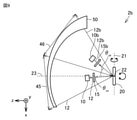
- the ranging device 1 of the present embodiment includes a light beam scanning device 2b instead of the light beam scanning device 2 (see FIG. 2).
- the light beam scanning device 2b further includes a light source 10b, an irradiation optical system 15b, a light beam splitter 16b, and a light receiving optical system 30b.
- the ranging device 1 of the present embodiment further includes an optical scanning region adaptive optics member 50.
- the light source 10b emits a light beam 12b.
- the light source 10b is a semiconductor laser and the light beam 12b is a laser beam.
- the light source 10b includes the same configuration as the light source 10 shown in FIG.
- the light source 10b includes a plurality of light emitting points.
- the light source 10b is a multimode laser, such as a high power horizontal multimode laser light source.
- the light source 10b has a light emitting region width so wide that it cannot be regarded as a point light source.
- the optical axes of the plurality of light sources 10, 10b are non-parallel to each other.
- the irradiation optical system 15b has the same function as the irradiation optical system 15. Specifically, the irradiation optical system 15b collimates the light beam 12b emitted from the light source 10b. As described above, the light source 10b has a light emitting region width so wide that it cannot be regarded as a point light source. Therefore, the light beam 12b that has passed through the irradiation optical system 15b has a second divergence angle, similarly to the light beam 12 that has passed through the irradiation optical system 15.
- the light beam splitter 16b has the same function as the light beam splitter 16.
- the light beam splitter 16b separates the light beam 12b from the return light 26b produced by the light beam 12b being reflected or scattered by at least one object 9 (see FIG. 1).
- the light beam splitter 16b reflects the light beam 12b toward the scanning mirror 20.
- the light beam splitter 16b transmits the return light 26b.
- the light beam splitter 16b may be configured in the same manner as the light beam splitter 16.
- the scanning mirror 20 further reflects and scans the light beam 12b.
- the scanning mirror 20 further scans the light beam 12b two-dimensionally.
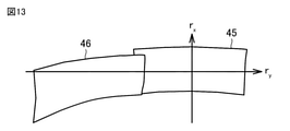
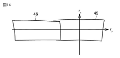
- the light beam 12 scanned by the scanning mirror 20 illuminates the light scanning region 45 (see FIG. 14).
- the light beam 12b scanned by the scanning mirror 20 illuminates the light scanning region 46 (see FIG. 14).
- the light receiving optical system 30b receives the return light 26b.
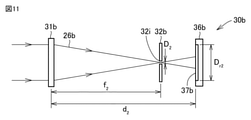
- the light receiving optical system 30b includes a condensing optical system 31b, an aperture 32b, and a light receiving element 36b.
- the condensing optical system 31b has the same function as the condensing optical system 31. Specifically, the condensing optical system 31b guides the return light 26b to the light receiving element 36b while condensing the light.
- the condensing optical system 31b includes, for example, a condensing lens.
- the condensing optical system 31b has a second focal length f 2 .
- the light receiving element 36b receives the return light 26b.
- the light receiving element 36b is, for example, a photodiode such as an avalanche photodiode or a single photon avalanche photodiode, or a silicon photomultiplier (SiPM).
- a photodiode such as an avalanche photodiode or a single photon avalanche photodiode, or a silicon photomultiplier (SiPM).
- SiPM silicon photomultiplier
- a faint return light 26b from can be detected. Therefore, the distance that can be measured by the distance measuring device 1 increases, and the distance measuring device 1 can obtain an accurate distance image of at least one object
- the light receiving element 36b includes a light receiving region 37b.
- the light receiving region 37b is a region of the light receiving element 36b that has sensitivity to the return light 26b.
- the return light 26b is incident on the light receiving region 37b.
- the light receiving region 37b has a diameter D r2 in the direction corresponding to the second divergence angle.
- the light receiving region 37b of the light receiving element 36b is separated from the condensing optical system 31 by a distance d 2 in the optical axis direction of the return light 26.
- the aperture 32b is arranged between the condensing optical system 31b and the light receiving element 36b.
- the aperture 32b is arranged on the second focal plane of the condensing optical system 31b.
- the aperture 32b is provided with a hole 32i.
- the aperture 32b limits the angular range of the return light 26b that can be incident on the light receiving element 36b. Since the light receiving optical system 30b includes the aperture 32b, the second viewing angle ⁇ 2 of the light receiving optical system 30b is given by arctan (D 2 / f 2 ). D 2 is the diameter of the hole 32i in the direction corresponding to the second divergence angle.
- the second viewing angle ⁇ 2 of the light receiving optical system 30b is smaller than the second divergence angle of the light beam 12b.
- the viewing angle ⁇ r2 of the light receiving optical system 30b in the absence of the aperture 32b is given by arctan (D r2 / d 2 ).
- the viewing angle ⁇ r2 of the light receiving optical system 30b in the absence of the aperture 32b is larger than the second divergence angle of the light beam 12b.
- the plurality of optical scanning regions 45, 46 are arranged in the first direction (x-axis).
- the distance measuring device 1 (light beam scanning device 2b) can expand the light scanning area in the first direction (x-axis).
- r x represents the angle of rotation of the scanning mirror 20 around the axis of rotation 21 (x-axis).
- ry (see FIGS. 13 and 14) represents the angle of rotation of the scanning mirror 20 around the axis of rotation 22 ( y -axis).
- one end of a pair of optical scanning regions adjacent to each other is the other end of the pair of optical scanning regions adjacent to each other. It overlaps only one end or touches the other end of a pair of light scanning regions adjacent to each other.
- the central region of one of the pair of optical scanning regions adjacent to each other is the other of the pair of optical scanning regions adjacent to each other. It does not overlap in the central part.
- the central region of one of the pair of optical scanning regions adjacent to each other is the direction in which the plurality of optical scanning regions 45, 46 are arranged from the other central portion of the pair of optical scanning regions adjacent to each other (first direction (x-axis)).
- the end portion of the optical scanning region 46 overlaps only the end portion of the optical scanning region 45. Or is in contact with the end of the optical scanning region 45.
- the central portion of the optical scanning region 46 does not overlap with the central portion of the optical scanning region 45.
- the central portion of the optical scanning region 46 is deviated from the central portion of the optical scanning region 45 in the direction in which the plurality of optical scanning regions 45, 46 are arranged (first direction (x-axis direction)).
- the direction in which the optical scanning region of the distance measuring device 1 is expanded by the end portion of the optical scanning region 45 overlapping only the end portion of the optical scanning region 46 or contacting the end portion of the optical scanning region 46 (in the present specification).
- the first direction) is the x-axis.
- the normal line 23 of the scanning mirror 20 when the scanning mirror 20 is in the center of the rotation range of the scanning mirror 20 corresponding to the plurality of optical scanning regions 45 and 46 is defined as the z-axis.
- the center of the rotation range of the scanning mirror 20 corresponding to the optical scanning region 45 and the center of the rotation range of the scanning mirror 20 corresponding to the optical scanning region 46 are the same as each other.
- the y-axis is perpendicular to the x-axis and the z-axis.
- the plane including the x-axis and the z-axis is referred to as a first plane (zx plane).
- the plane including the z-axis and the y-axis is referred to as a second plane (yz plane).
- the second angle ⁇ yb is the first angle ⁇ ya as shown in FIG. Because it is different. As shown in FIG. 12, the first angle ⁇ ya is the angle between the first optical axis and the z-axis of the light beam 12 incident on the scanning mirror 20 projected on the first plane (zx plane). be. That is, the first angle ⁇ ya is the angle of incidence of the light beam 12 on the scanning mirror 20 projected on the first plane (zx plane).
- the second angle ⁇ yb is an angle between the second optical axis and the z-axis of the light beam 12b projected on the first plane (zx plane) and incident on the scanning mirror 20. That is, the second angle ⁇ yb is the angle of incidence of the light beam 12b on the scanning mirror 20 projected on the first plane (zx plane). In this embodiment, the second angle ⁇ yb is larger than the first angle ⁇ ya .
- the optical axes of the plurality of optical beams 12 and 12b projected on the first plane (zx plane) and incident on the scanning mirror 20 As shown in FIG. 13, without the optical scanning region correction optical member 50, the optical axes of the plurality of optical beams 12 and 12b projected on the first plane (zx plane) and incident on the scanning mirror 20.
- the distortion of each of the plurality of optical scanning regions 45 and 46 formed by each of the plurality of scanned optical beams 12, 12b becomes large.
- the second angle ⁇ yb between the second optical axis and the z-axis of the light beam 12b incident on the scanning mirror 20 projected on the first plane (zx plane) is the first plane (zx). It is larger than the first angle ⁇ ya between the first optical axis and the z-axis of the light beam 12 incident on the scanning mirror 20 projected on the plane). That is, the second incident angle of the light beam 12b projected on the first plane (zx plane) to the scanning mirror 20 is the light beam 12 projected onto the first plane (zx plane). Larger than the first angle of incidence. Without the optical scanning region correction optical member 50, the distortion of the optical scanning region 46 formed by the optical beam 12b scanned by the scanning mirror 20 is the distortion of the optical scanning region 45 formed by the optical beam 12 scanned by the scanning mirror 20. Greater than distortion.
- the optical scanning region correction optical member 50 is, for example, a lens having a free curved surface shape (see FIGS. 9 and 10) or a mirror having a free curved surface shape.
- the optical scanning region correction optical member 50 corrects at least one of the plurality of optical scanning regions 45, 46 formed by the plurality of optical beams 12, 12b scanned by the scanning mirror 20. Specifically, the optical scanning region correction optical member 50 corrects all of the plurality of optical scanning regions 45, 46 formed by the plurality of optical beams 12, 12b scanned by the scanning mirror 20.
- the correction optical member 50 gives a stronger negative power to each of the plurality of light beams 12 and 12b. In this way, the larger the angle between the optical axis of each of the plurality of optical beams 12 and 12b projected on the first plane (zx plane) and the light beams 12 and 12b incident on the scanning mirror 20, the larger the optical scanning region correction optical member. 50 more largely corrects the distortion of each of the plurality of optical scanning regions 45, 46 corresponding to each of the plurality of optical beams 12, 12b.
- the optical scanning region adaptive optics member 50 gives a relatively weak negative power to the light beam 12, while giving a relatively strong negative power to the light beam 12b. Therefore, the optical scanning region correction optical member 50 corrects the distortion of the optical scanning region 46 to be larger than the distortion of the optical scanning region 45. The difference between the shape of the optical scanning region 45 and the shape of the optical scanning region 46 is reduced.
- Each of the plurality of optical scanning regions 45, 46 has a desired shape, such as a substantially rectangular shape.
- each of the plurality of light beams 12, 12b receives a stronger negative power from the optical scanning region adaptive optics member 50, the larger each of the plurality of light beams 12, 12b expands.
- Each of the plurality of optical scanning regions 45, 46 corresponding to each of the plurality of optical beams 12, 12b is such that each of the plurality of optical beams 12, 12b receives a stronger negative power from the optical scanning region correction optical member 50. Irradiated with a lower light intensity per unit area, the light intensity of each of the plurality of return lights 26, 26b corresponding to each of the plurality of light beams 12, 12b is reduced.
- the distance measurement of at least one object 9 using each of the plurality of light beams 12 and 12b is such that each of the plurality of light beams 12 and 12b receives a stronger negative power from the optical scanning region adaptive optics member 50.
- the possible distance or range is reduced.
- the distance or range that can be measured varies among the plurality of optical scanning areas 45 and 46.
- the optical scanning region adaptive optics member 50 gives a relatively weak negative power to the light beam 12, while giving a relatively strong negative power to the light beam 12b. Therefore, the light beam 12b expands more than the light beam 12.
- the light intensity per unit area of the light beam 12b irradiated on at least one object 9 is lower than the light intensity per unit area of the light beam 12 irradiated on at least one object 9.
- the light intensity of the return light 26b is lower than the light intensity of the return light 26.
- the distance or range that can be measured by at least one object 9 using the light beam 12b is smaller than the distance or range that can be measured by at least one object 9 using the light beam 12. The distance or range that can be measured varies among the plurality of optical scanning areas 45 and 46.
- each of the plurality of light beams 12 and 12b spreads larger as a stronger negative power is given by the optical scanning region adaptive optics member 50, and irradiates at least one object 9 with a wider area. .. Therefore, the more the plurality of optical beams 12, 12b each receive a stronger negative power from the optical scanning region correction optical member 50, the more the plurality of optical scanning regions 45, 46 formed by each of the plurality of optical beams 12, 12b.
- the resolution of the ranging device 1 in each is lowered. The resolution of the ranging device 1 varies among the plurality of optical scanning regions 45 and 46.
- the optical scanning region adaptive optics member 50 gives a relatively weak negative power to the light beam 12, while giving a relatively strong negative power to the light beam 12b. Therefore, the light beam 12b expands more than the light beam 12.
- the area of the light beam 12b irradiated on at least one object 9 is larger than the area of the light beam 12 irradiated on at least one object 9.
- the resolution of the distance measuring device 1 in the optical scanning region 46 formed by the light beam 12b is lower than the resolution of the ranging device 1 in the optical scanning region 45 formed by the light beam 12.
- the diameter D 2 of the hole 32i of the aperture 32b is set to the aperture 32 according to the strength of the negative power received from the optical scanning region adaptive optics member 50 by each of the plurality of light beams 12 and 12b. It is different from the diameter D 1 of the hole 32h.
- the diameters D 1 and D 2 of the holes 32h and 32i of the plurality of apertures 32 and 32b corresponding to the light 26 and 26b are increased.
- the light beam 12b receives a stronger negative power from the optical scanning region adaptive optics member 50 than the light beam 12.
- the diameter D 2 of the hole 32i of the aperture 32b corresponding to the return light 26b corresponding to the light beam 12b is made larger than the diameter D 1 of the hole 32h of the aperture 32 corresponding to the return light 26 corresponding to the light beam 12.
- each of the plurality of return lights 26, 26b corresponding to each of the plurality of light beams 12, 12b that receive a stronger negative power from the optical scanning area correction optical member 50 is larger, and the plurality of return lights 26, 26b are present.
- the measurable distance and range of at least one object 9 using the light beam 12b can be increased.
- the distance measuring device 1 increases the distance or range that can be measured. Further, the distance and range of the at least one object 9 using the light beam 12b shall be close to or equal to the distance and range of the at least one object 9 using the light beam 12. Can be done. It is possible to reduce the variation in the distance or range that can be measured between the plurality of optical scanning areas 45 and 46.
- the plurality of light beams 12, 12b corresponding to each of the plurality of light beams 12, 12b so that each of the plurality of light beams 12, 12b receives a stronger negative power from the optical scanning region correction optical member 50.
- the diameters D 1 and D 2 of the holes 32h and 32i of the plurality of apertures 32 and 32b corresponding to the return lights 26 and 26b of the above are reduced.
- the light beam 12b receives a stronger negative power from the optical scanning region adaptive optics member 50 than the light beam 12.
- the diameter D 2 of the hole 32i of the aperture 32b is made smaller than the diameter D 1 of the hole 32h of the aperture 32.
- the angle range in which the light can be incident on each of the plurality of light receiving elements 36, 36b corresponding to each of the plurality of return lights 26, 26b is small. Specifically, the angular range of the return light 26b that can be incident on the light receiving element 36b through the aperture 32b is smaller than the angular range of the return light 26 that can be incident on the light receiving element 36 through the aperture 32. .. It is possible to improve the resolution of the distance measuring device 1 in the optical scanning region 46 formed by the optical beam 12b.
- the resolution of the ranging device 1 in the optical scanning region 46 formed by the light beam 12b can be made close to or equal to the resolution of the ranging device 1 in the optical scanning region 45 formed by the light beam 12. It is possible to reduce the variation in the resolution of the distance measuring device 1 among the plurality of optical scanning regions 45 and 46.
- the plurality of light sources 10, 10b are arranged on one side (+ y direction side) with respect to the first plane (zx plane).
- the angle between the optical axis and the z-axis of each of the plurality of light beams 12, 12b projected on the scanning mirror 20 is large.
- the incident angles of the plurality of light beams 12 and 12b to the light beam 12 and 12b are large. Therefore, the deviation between the plurality of optical scanning regions 45 and 46 in the y-axis direction perpendicular to the x-axis and the z-axis is reduced. The continuity of the plurality of optical scanning regions 45 and 46 is improved.
- the second angle ⁇ yb between the second optical axis and the z-axis of the light beam 12b incident on the scanning mirror 20 projected on the first plane (zx plane) is the first plane (zx). It is larger than the first angle ⁇ ya between the first optical axis and the z-axis of the light beam 12 incident on the scanning mirror 20 projected on the plane). That is, the incident angle of the light beam 12b on the scanning mirror 20 projected on the first plane (zx plane) is the incident angle of the light beam 12 on the scanning mirror 20 projected on the first plane (zx plane). Greater.
- the fourth angle ⁇ xb between the second optical axis and the z-axis of the light beam 12b incident on the scanning mirror 20 projected on the second plane (yz plane) is on the second plane (yz plane). It is larger than the projected third angle ⁇ xa (see FIG. 12) between the first optical axis and the z-axis of the light beam 12 incident on the scanning mirror 20. That is, the incident angle of the light beam 12b on the scanning mirror 20 projected on the second plane (yz plane) is the incident angle of the light beam 12 on the scanning mirror 20 projected on the second plane (yz plane). Greater.
- the controller 4 is further communicably connected to the light source 10b and the light receiving element 36b.
- the controller 4 controls the light sources 10 and 10b to control the timing at which the pulsed light beam 12b is emitted from the light sources 10 and 10b.
- the controller 4 receives the first timing from the light sources 10 and 10b when the light sources 10 and 10b emit the light beams 12 and 12b.
- the controller 4 receives a signal from the light receiving elements 36, 36b according to the amount of light of the return light 26, 26b received by the light receiving elements 36, 36b.
- the controller 4 receives the second timing at which the light receiving elements 36, 36b receive the return light 26, 26b.
- the arithmetic unit 5 calculates the emission directions of the light beams 12 and 12b from the tilt angle of the scanning mirror 20 received by the controller 4 and the positions of the light sources 10 and 10b with respect to the scanning mirror 20 stored in the storage device 6.
- the calculator 5 receives from the controller 4 the first timing at which the light sources 10 and 10b emit the light beams 12 and 12b.
- the calculator 5 receives from the controller 4 the second timing at which the light receiving elements 36, 36b receive the return light 26, 26b.
- the arithmetic unit 5 Based on the above, the distance from the distance measuring device 1 to at least one object 9 and the direction of at least one object 9 with respect to the distance measuring device 1 are calculated.
- the arithmetic unit 5 generates a distance image of at least one object 9 as in the first embodiment. Similar to the first embodiment, the arithmetic unit 5 outputs a distance image of at least one object 9 to a display device (not shown).
- the light diffusing element 33 or the diffractive optical element is arranged between the aperture 32 and the light receiving element 36, as in the first modification of the first embodiment (see FIG. 5). At the same time, the light diffusing element 33 or the diffractive optical element is arranged between the aperture 32b and the light receiving element 36b.
- the rear aperture 34 is arranged between the aperture 32 and the light receiving element 36, and the second rear aperture is the aperture, as in the second embodiment (see FIG. 7). It is arranged between the 32b and the light receiving element 36b.
- the number of the plurality of light sources 10, 10b is three or more.
- the effect of the distance measuring device 1 of the present embodiment has the following effects in addition to the effect of the distance measuring device 1 of the first embodiment.
- the ranging device 1 of the present embodiment further includes an optical scanning region adaptive optics member 50.
- the optical scanning region correction optical member 50 corrects the first optical scanning region (optical scanning region 45) formed by the first optical beam (optical beam 12) scanned by the scanning mirror 20.
- the optical scanning region 45 can be made into a more desirable shape by using the optical scanning region adaptive optics member 50, and the resolution of the ranging device 1 can be improved.
- the distance measuring device 1 of the present embodiment further includes a second light source (light source 10b) and a second light receiving optical system (light receiving optical system 30b).
- the second light source emits a second light beam (light beam 12b).
- the second light receiving optical system receives the second return light (return light 26b) generated by the reflection or scattering of the second light beam by at least one object 9.
- the scanning mirror 20 further scans the second light beam.
- the optical scanning region correction optical member 50 further corrects the second optical scanning region (optical scanning region 46) formed by the second optical beam scanned by the scanning mirror 20.
- the second light receiving optical system is located between the second light receiving optical system (condensing optical system 31b), the second light receiving element (light receiving element 36b), and the second light receiving optical system and the second light receiving element.
- the second aperture is arranged on the second focal plane of the second condensing optical system.
- the second viewing angle ⁇ 2 of the second light receiving optical system is smaller than the second divergence angle of the second light beam.
- the second viewing angle ⁇ 2 is given by arctan (D 2 / f 2 ).
- f 2 represents the second focal length of the second condensing optical system
- D 2 represents the second diameter (diameter D 2 ) of the second hole (hole 32i) provided in the second aperture.
- the second diameter of the second hole of the second aperture is different from the first diameter (diameter D 1 ) of the first hole (hole 32h) of the first aperture (aperture 32).
- the second aperture (aperture 32b) can be incident on the second light receiving element (light receiving element 36b). 2 Limits the angular range of the return light (return light 26b). Therefore, the resolution of the ranging device 1 can be improved.
- the second diameter (diameter D 2 ) of the second hole (hole 32i) of the second aperture (aperture 32b) is the first diameter (diameter D) of the first hole (hole 32h) of the first aperture (aperture 32). It is different from 1 ). Therefore, the distance or range that can be measured by the distance measuring device 1 varies over the entire first optical scanning area (optical scanning area 45) and the second optical scanning area (optical scanning area 46), or the distance measuring device 1 It is possible to reduce the variation in the resolution of.
- the first end portion of the first optical scanning region overlaps only the second end portion of the second optical scanning region (optical scanning region 46) or the second end portion.
- the direction in which the optical scanning region of the distance measuring device 1 is expanded by being in contact with the second end of the optical scanning region is defined as the first axis (x-axis).
- the normal line 23 of the scanning mirror 20 when the scanning mirror 20 is in the center of the rotation range of the scanning mirror 20 corresponding to the first optical scanning region and the second optical scanning region is defined as the second axis (z-axis).
- the second diameter (diameter D 2 ) of the second hole (hole 32i) of the second aperture (aperture 32b) is the first diameter (diameter D 1 ) of the first hole (hole 32h) of the first aperture (aperture 32). Greater.
- the amount of light of the second return light (return light 26b) passing through the second aperture (aperture 32b) can be increased.
- the measurable distance and range of at least one object 9 using the second light beam (light beam 12b) can be increased.
- the distance measuring device 1 increases the distance or range that can be measured. Further, the distance and range that can be measured by at least one object 9 using the second light beam (light beam 12b) can be measured by measuring at least one object 9 using the first light beam (light beam 12). Can be close to or equal to the distance and range that can be distanced. It is possible to reduce the variation in the distance or range that can be measured between the first optical scanning region (optical scanning region 45) and the second optical scanning region (optical scanning region 46).
- the distance measuring device 1 of the present embodiment includes a plurality of light sources 10, 10b, a scanning mirror 20, an optical scanning region adaptive optics member 50, and a plurality of light receiving optical systems 30, 30b.
- the plurality of light sources 10, 10b emit a plurality of light beams 12, 12b, respectively.
- the scanning mirror 20 scans a plurality of light beams 12, 12b.
- the optical scanning region correction optical member 50 corrects at least one of the plurality of optical scanning regions 45, 46 formed by the plurality of optical beams 12, 12b scanned by the scanning mirror 20.
- the plurality of light receiving optical systems 30 and 30b receive a plurality of return lights 26 and 26b generated by the plurality of light beams 12 and 12b being reflected or scattered by at least one object 9, respectively.
- the plurality of light receiving optical systems 30 and 30b have apertures 32 and 32b between the condensing optical systems 31, 31b, the light receiving elements 36 and 36b, and the condensing optical systems 31, 31b and the light receiving elements 36 and 36b, respectively. And include.
- the apertures 32 and 32b are arranged on the focal planes of the focusing optical systems 31 and 31b.
- the viewing angle of the light receiving optical systems 30 and 30b is smaller than the divergence angle of each of the plurality of light beams 12 and 12b corresponding to the light receiving optical systems 30 and 30b.
- the viewing angles of the light receiving optical systems 30 and 30b are given by arctan (D / f).
- f represents the focal length of the condensing optical systems 31, 31b.
- D represents the diameter of the holes 32h and 32i provided in the apertures 32 and 32b.
- the direction in which the optical scanning region is expanded by contacting the second end is defined as the first axis (x-axis).
- the normal line 23 of the scanning mirror 20 when the scanning mirror 20 is in the center of the rotation range of the scanning mirror 20 corresponding to the plurality of optical scanning regions 45 and 46 is defined as the second axis (z-axis).
- the distance or range that can be measured by the distance measuring device 1 increases. It is possible to reduce the variation in the distance or range that can be measured between the plurality of optical scanning areas 45 and 46.
- the first end portion of the first optical scanning region overlaps only the second end portion of the second optical scanning region (optical scanning region 46) or the second end portion.
- the direction in which the optical scanning region of the distance measuring device 1 is expanded by being in contact with the second end of the optical scanning region is defined as the first axis (x-axis).
- the normal line 23 of the scanning mirror 20 when the scanning mirror 20 is in the center of the rotation range of the scanning mirror 20 corresponding to the first optical scanning region and the second optical scanning region is defined as the second axis (z-axis).
- the second hole (hole 32i) second diameter (diameter D 2 ) of the second aperture (aperture 32b) is from the first diameter (diameter D 1 ) of the first hole (hole 32h) of the first aperture (aperture 32). small.
- the resolution of the distance measuring device 1 in the second light scanning region (light scanning region 46) formed by the second light beam (light beam 12b) can be improved. Further, the resolution of the distance measuring device 1 in the second light scanning region (light scanning region 46) formed by the second light beam (light beam 12b) is determined by the first light scanning formed by the first light beam (light beam 12). The resolution of the ranging device 1 in the region (optical scanning region 45) can be approached or equalized. It is possible to reduce the variation in the resolution of the distance measuring device 1 between the first optical scanning region (optical scanning region 45) and the second optical scanning region (optical scanning region 46).
- the distance measuring device 1 of the present embodiment includes a plurality of light sources 10, 10b, a scanning mirror 20, an optical scanning region adaptive optics member 50, and a plurality of light receiving optical systems 30, 30b.
- the plurality of light sources 10, 10b emit a plurality of light beams 12, 12b, respectively.
- the scanning mirror 20 scans a plurality of light beams 12, 12b.
- the optical scanning region correction optical member 50 corrects at least one of the plurality of optical scanning regions 45, 46 formed by the plurality of optical beams 12, 12b scanned by the scanning mirror 20.
- the plurality of light receiving optical systems 30 and 30b receive a plurality of return lights 26 and 26b generated by the plurality of light beams 12 and 12b being reflected or scattered by at least one object 9, respectively.
- the plurality of light receiving optical systems 30 and 30b have apertures 32 and 32b between the condensing optical systems 31, 31b, the light receiving elements 36 and 36b, and the condensing optical systems 31, 31b and the light receiving elements 36 and 36b, respectively. And include.
- the apertures 32 and 32b are arranged on the focal planes of the focusing optical systems 31 and 31b.
- the viewing angle of the light receiving optical systems 30 and 30b is smaller than the divergence angle of each of the plurality of light beams 12 and 12b corresponding to the light receiving optical systems 30 and 30b.
- the viewing angles of the light receiving optical systems 30 and 30b are given by arctan (D / f).
- f represents the focal length of the condensing optical systems 31, 31b.
- D represents the diameter of the holes 32h and 32i provided in the apertures 32 and 32b.
- the direction in which the optical scanning region is expanded by contacting the second end is defined as the first axis (x-axis).
- the normal line 23 of the scanning mirror 20 when the scanning mirror 20 is in the center of the rotation range of the scanning mirror 20 corresponding to the plurality of optical scanning regions 45 and 46 is defined as the second axis (z-axis).
- the distance or range that can be measured with improved resolution increases. It is possible to reduce the variation in the resolution of the distance measuring device 1 among the plurality of optical scanning regions 45 and 46.
Landscapes
- Engineering & Computer Science (AREA)
- Physics & Mathematics (AREA)
- General Physics & Mathematics (AREA)
- Computer Networks & Wireless Communication (AREA)
- Radar, Positioning & Navigation (AREA)
- Remote Sensing (AREA)
- Electromagnetism (AREA)
- Optics & Photonics (AREA)
- Optical Radar Systems And Details Thereof (AREA)
- Measurement Of Optical Distance (AREA)
- Mechanical Optical Scanning Systems (AREA)
Priority Applications (4)
| Application Number | Priority Date | Filing Date | Title |
|---|---|---|---|
| DE112020007572.9T DE112020007572T5 (de) | 2020-08-31 | 2020-08-31 | Abstandsmessvorrichtung |
| US18/015,538 US20230258779A1 (en) | 2020-08-31 | 2020-08-31 | Distance measurement apparatus |
| JP2022545249A JP7483016B2 (ja) | 2020-08-31 | 2020-08-31 | 測距装置 |
| PCT/JP2020/032857 WO2022044317A1 (ja) | 2020-08-31 | 2020-08-31 | 測距装置 |
Applications Claiming Priority (1)
| Application Number | Priority Date | Filing Date | Title |
|---|---|---|---|
| PCT/JP2020/032857 WO2022044317A1 (ja) | 2020-08-31 | 2020-08-31 | 測距装置 |
Publications (1)
| Publication Number | Publication Date |
|---|---|
| WO2022044317A1 true WO2022044317A1 (ja) | 2022-03-03 |
Family
ID=80354895
Family Applications (1)
| Application Number | Title | Priority Date | Filing Date |
|---|---|---|---|
| PCT/JP2020/032857 Ceased WO2022044317A1 (ja) | 2020-08-31 | 2020-08-31 | 測距装置 |
Country Status (4)
| Country | Link |
|---|---|
| US (1) | US20230258779A1 (https=) |
| JP (1) | JP7483016B2 (https=) |
| DE (1) | DE112020007572T5 (https=) |
| WO (1) | WO2022044317A1 (https=) |
Citations (5)
| Publication number | Priority date | Publication date | Assignee | Title |
|---|---|---|---|---|
| JP2001343602A (ja) * | 2000-03-29 | 2001-12-14 | Canon Inc | 光走査光学系及びそれを用いた画像形成装置 |
| JP2004151674A (ja) * | 2002-09-06 | 2004-05-27 | Hitachi Ltd | 投射型映像表示装置 |
| WO2017183530A1 (ja) * | 2016-04-21 | 2017-10-26 | コニカミノルタ株式会社 | 対象物検出装置 |
| JP6519033B1 (ja) * | 2018-07-03 | 2019-05-29 | Dolphin株式会社 | 物体検出装置、物体検出方法、および物体検出装置の設計方法 |
| JP2020515812A (ja) * | 2016-12-13 | 2020-05-28 | センスル テクノロジーズ リミテッド | ライダー装置 |
Family Cites Families (1)
| Publication number | Priority date | Publication date | Assignee | Title |
|---|---|---|---|---|
| KR102554215B1 (ko) * | 2016-09-20 | 2023-07-11 | 이노비즈 테크놀로지스 엘티디 | Lidar 시스템 및 방법 |
-
2020
- 2020-08-31 WO PCT/JP2020/032857 patent/WO2022044317A1/ja not_active Ceased
- 2020-08-31 DE DE112020007572.9T patent/DE112020007572T5/de active Pending
- 2020-08-31 JP JP2022545249A patent/JP7483016B2/ja active Active
- 2020-08-31 US US18/015,538 patent/US20230258779A1/en active Pending
Patent Citations (5)
| Publication number | Priority date | Publication date | Assignee | Title |
|---|---|---|---|---|
| JP2001343602A (ja) * | 2000-03-29 | 2001-12-14 | Canon Inc | 光走査光学系及びそれを用いた画像形成装置 |
| JP2004151674A (ja) * | 2002-09-06 | 2004-05-27 | Hitachi Ltd | 投射型映像表示装置 |
| WO2017183530A1 (ja) * | 2016-04-21 | 2017-10-26 | コニカミノルタ株式会社 | 対象物検出装置 |
| JP2020515812A (ja) * | 2016-12-13 | 2020-05-28 | センスル テクノロジーズ リミテッド | ライダー装置 |
| JP6519033B1 (ja) * | 2018-07-03 | 2019-05-29 | Dolphin株式会社 | 物体検出装置、物体検出方法、および物体検出装置の設計方法 |
Also Published As
| Publication number | Publication date |
|---|---|
| DE112020007572T5 (de) | 2023-06-22 |
| JPWO2022044317A1 (https=) | 2022-03-03 |
| JP7483016B2 (ja) | 2024-05-14 |
| US20230258779A1 (en) | 2023-08-17 |
Similar Documents
| Publication | Publication Date | Title |
|---|---|---|
| JP7019894B2 (ja) | 物体を感知する方法及びセンサシステム | |
| US10996322B2 (en) | Lidar sensor | |
| CN114651194B (zh) | 用于固态lidar系统的投影仪 | |
| WO2019146647A1 (ja) | ライダー装置、運転支援システム、及び車両 | |
| JP7234816B2 (ja) | 測距装置 | |
| JP2018005183A (ja) | 光走査装置、物体検知装置および距離検知装置 | |
| TWI551952B (zh) | Euv微影系統 | |
| JP2014240782A (ja) | 計測装置 | |
| TW201942543A (zh) | 測距單元及光照射裝置 | |
| JP2013002819A (ja) | 平面度測定装置 | |
| US12487335B2 (en) | Receiving system for lidar, lidar and method for inhibiting ghost lines | |
| WO2021192601A1 (ja) | ラインビーム走査光学系およびレーザレーダ | |
| CN111164450B (zh) | 用于根据激光雷达原理的距离测量设备的光学装置 | |
| CN114174862B (zh) | 用于光学地测量与漫射目标物体和反射目标物体的距离的设备 | |
| CN107683424A (zh) | 用于光学地测量与反射的目标物体的距离的设备 | |
| JP7483016B2 (ja) | 測距装置 | |
| US11486967B2 (en) | Module for a lidar sensor and lidar sensor | |
| JP2019023650A (ja) | 光波距離測定装置 | |
| US20240329204A1 (en) | Distance measuring apparatus | |
| CN114488080A (zh) | 匀光片、可用于激光雷达的光发射单元和激光雷达 | |
| WO2021240978A1 (ja) | ビーム走査光学系およびレーザレーダ | |
| JP4414183B2 (ja) | レーザ光送受光装置 | |
| JP2016186470A (ja) | レーザレーダ装置、および、光学部品の配置決定方法 | |
| JP7155526B2 (ja) | ライダー装置 | |
| US12607722B2 (en) | Optical waveguide device used in laser detection and ranging system |
Legal Events
| Date | Code | Title | Description |
|---|---|---|---|
| 121 | Ep: the epo has been informed by wipo that ep was designated in this application |
Ref document number: 20951566 Country of ref document: EP Kind code of ref document: A1 |
|
| ENP | Entry into the national phase |
Ref document number: 2022545249 Country of ref document: JP Kind code of ref document: A |
|
| 122 | Ep: pct application non-entry in european phase |
Ref document number: 20951566 Country of ref document: EP Kind code of ref document: A1 |