WO2022039021A1 - Dispositif de détermination de congestion de véhicule et dispositif de commande d'affichage de véhicule - Google Patents
Dispositif de détermination de congestion de véhicule et dispositif de commande d'affichage de véhicule Download PDFInfo
- Publication number
- WO2022039021A1 WO2022039021A1 PCT/JP2021/028826 JP2021028826W WO2022039021A1 WO 2022039021 A1 WO2022039021 A1 WO 2022039021A1 JP 2021028826 W JP2021028826 W JP 2021028826W WO 2022039021 A1 WO2022039021 A1 WO 2022039021A1
- Authority
- WO
- WIPO (PCT)
- Prior art keywords
- vehicle
- information
- display
- automatic driving
- threshold value
- Prior art date
Links
- 238000004891 communication Methods 0.000 description 39
- 238000012544 monitoring process Methods 0.000 description 23
- 230000002093 peripheral effect Effects 0.000 description 23
- 230000006870 function Effects 0.000 description 14
- 238000001514 detection method Methods 0.000 description 13
- 230000015654 memory Effects 0.000 description 13
- 238000000034 method Methods 0.000 description 11
- 230000007704 transition Effects 0.000 description 10
- 230000001133 acceleration Effects 0.000 description 5
- 238000013459 approach Methods 0.000 description 4
- 230000008859 change Effects 0.000 description 4
- 230000008569 process Effects 0.000 description 4
- 230000000694 effects Effects 0.000 description 3
- 238000012986 modification Methods 0.000 description 3
- 230000004048 modification Effects 0.000 description 3
- 238000012545 processing Methods 0.000 description 3
- 238000004590 computer program Methods 0.000 description 2
- 230000000007 visual effect Effects 0.000 description 2
- 125000002066 L-histidyl group Chemical group [H]N1C([H])=NC(C([H])([H])[C@](C(=O)[*])([H])N([H])[H])=C1[H] 0.000 description 1
- 230000003044 adaptive effect Effects 0.000 description 1
- 230000005540 biological transmission Effects 0.000 description 1
- 230000001413 cellular effect Effects 0.000 description 1
- 150000001875 compounds Chemical class 0.000 description 1
- 238000010276 construction Methods 0.000 description 1
- 201000010099 disease Diseases 0.000 description 1
- 208000037265 diseases, disorders, signs and symptoms Diseases 0.000 description 1
- 239000000284 extract Substances 0.000 description 1
- 238000003384 imaging method Methods 0.000 description 1
- 239000004973 liquid crystal related substance Substances 0.000 description 1
- 230000007774 longterm Effects 0.000 description 1
- 206010025482 malaise Diseases 0.000 description 1
- 235000012054 meals Nutrition 0.000 description 1
- 238000005259 measurement Methods 0.000 description 1
- 238000013508 migration Methods 0.000 description 1
- 230000005012 migration Effects 0.000 description 1
- 230000003287 optical effect Effects 0.000 description 1
Images


Classifications
-
- B—PERFORMING OPERATIONS; TRANSPORTING
- B60—VEHICLES IN GENERAL
- B60W—CONJOINT CONTROL OF VEHICLE SUB-UNITS OF DIFFERENT TYPE OR DIFFERENT FUNCTION; CONTROL SYSTEMS SPECIALLY ADAPTED FOR HYBRID VEHICLES; ROAD VEHICLE DRIVE CONTROL SYSTEMS FOR PURPOSES NOT RELATED TO THE CONTROL OF A PARTICULAR SUB-UNIT
- B60W50/00—Details of control systems for road vehicle drive control not related to the control of a particular sub-unit, e.g. process diagnostic or vehicle driver interfaces
- B60W50/08—Interaction between the driver and the control system
- B60W50/14—Means for informing the driver, warning the driver or prompting a driver intervention
-
- B—PERFORMING OPERATIONS; TRANSPORTING
- B60—VEHICLES IN GENERAL
- B60W—CONJOINT CONTROL OF VEHICLE SUB-UNITS OF DIFFERENT TYPE OR DIFFERENT FUNCTION; CONTROL SYSTEMS SPECIALLY ADAPTED FOR HYBRID VEHICLES; ROAD VEHICLE DRIVE CONTROL SYSTEMS FOR PURPOSES NOT RELATED TO THE CONTROL OF A PARTICULAR SUB-UNIT
- B60W60/00—Drive control systems specially adapted for autonomous road vehicles
- B60W60/005—Handover processes
- B60W60/0053—Handover processes from vehicle to occupant
-
- B—PERFORMING OPERATIONS; TRANSPORTING
- B60—VEHICLES IN GENERAL
- B60K—ARRANGEMENT OR MOUNTING OF PROPULSION UNITS OR OF TRANSMISSIONS IN VEHICLES; ARRANGEMENT OR MOUNTING OF PLURAL DIVERSE PRIME-MOVERS IN VEHICLES; AUXILIARY DRIVES FOR VEHICLES; INSTRUMENTATION OR DASHBOARDS FOR VEHICLES; ARRANGEMENTS IN CONNECTION WITH COOLING, AIR INTAKE, GAS EXHAUST OR FUEL SUPPLY OF PROPULSION UNITS IN VEHICLES
- B60K35/00—Instruments specially adapted for vehicles; Arrangement of instruments in or on vehicles
- B60K35/20—Output arrangements, i.e. from vehicle to user, associated with vehicle functions or specially adapted therefor
- B60K35/21—Output arrangements, i.e. from vehicle to user, associated with vehicle functions or specially adapted therefor using visual output, e.g. blinking lights or matrix displays
- B60K35/22—Display screens
-
- B—PERFORMING OPERATIONS; TRANSPORTING
- B60—VEHICLES IN GENERAL
- B60K—ARRANGEMENT OR MOUNTING OF PROPULSION UNITS OR OF TRANSMISSIONS IN VEHICLES; ARRANGEMENT OR MOUNTING OF PLURAL DIVERSE PRIME-MOVERS IN VEHICLES; AUXILIARY DRIVES FOR VEHICLES; INSTRUMENTATION OR DASHBOARDS FOR VEHICLES; ARRANGEMENTS IN CONNECTION WITH COOLING, AIR INTAKE, GAS EXHAUST OR FUEL SUPPLY OF PROPULSION UNITS IN VEHICLES
- B60K35/00—Instruments specially adapted for vehicles; Arrangement of instruments in or on vehicles
- B60K35/20—Output arrangements, i.e. from vehicle to user, associated with vehicle functions or specially adapted therefor
- B60K35/28—Output arrangements, i.e. from vehicle to user, associated with vehicle functions or specially adapted therefor characterised by the type of the output information, e.g. video entertainment or vehicle dynamics information; characterised by the purpose of the output information, e.g. for attracting the attention of the driver
-
- B—PERFORMING OPERATIONS; TRANSPORTING
- B60—VEHICLES IN GENERAL
- B60W—CONJOINT CONTROL OF VEHICLE SUB-UNITS OF DIFFERENT TYPE OR DIFFERENT FUNCTION; CONTROL SYSTEMS SPECIALLY ADAPTED FOR HYBRID VEHICLES; ROAD VEHICLE DRIVE CONTROL SYSTEMS FOR PURPOSES NOT RELATED TO THE CONTROL OF A PARTICULAR SUB-UNIT
- B60W60/00—Drive control systems specially adapted for autonomous road vehicles
- B60W60/005—Handover processes
- B60W60/0053—Handover processes from vehicle to occupant
- B60W60/0055—Handover processes from vehicle to occupant only part of driving tasks shifted to occupants
-
- B—PERFORMING OPERATIONS; TRANSPORTING
- B60—VEHICLES IN GENERAL
- B60W—CONJOINT CONTROL OF VEHICLE SUB-UNITS OF DIFFERENT TYPE OR DIFFERENT FUNCTION; CONTROL SYSTEMS SPECIALLY ADAPTED FOR HYBRID VEHICLES; ROAD VEHICLE DRIVE CONTROL SYSTEMS FOR PURPOSES NOT RELATED TO THE CONTROL OF A PARTICULAR SUB-UNIT
- B60W60/00—Drive control systems specially adapted for autonomous road vehicles
- B60W60/005—Handover processes
- B60W60/0057—Estimation of the time available or required for the handover
-
- G—PHYSICS
- G08—SIGNALLING
- G08G—TRAFFIC CONTROL SYSTEMS
- G08G1/00—Traffic control systems for road vehicles
- G08G1/01—Detecting movement of traffic to be counted or controlled
- G08G1/0104—Measuring and analyzing of parameters relative to traffic conditions
- G08G1/0125—Traffic data processing
- G08G1/0133—Traffic data processing for classifying traffic situation
-
- G—PHYSICS
- G08—SIGNALLING
- G08G—TRAFFIC CONTROL SYSTEMS
- G08G1/00—Traffic control systems for road vehicles
- G08G1/09—Arrangements for giving variable traffic instructions
- G08G1/0962—Arrangements for giving variable traffic instructions having an indicator mounted inside the vehicle, e.g. giving voice messages
- G08G1/09623—Systems involving the acquisition of information from passive traffic signs by means mounted on the vehicle
-
- G—PHYSICS
- G08—SIGNALLING
- G08G—TRAFFIC CONTROL SYSTEMS
- G08G1/00—Traffic control systems for road vehicles
- G08G1/09—Arrangements for giving variable traffic instructions
- G08G1/0962—Arrangements for giving variable traffic instructions having an indicator mounted inside the vehicle, e.g. giving voice messages
- G08G1/0967—Systems involving transmission of highway information, e.g. weather, speed limits
- G08G1/096708—Systems involving transmission of highway information, e.g. weather, speed limits where the received information might be used to generate an automatic action on the vehicle control
- G08G1/096725—Systems involving transmission of highway information, e.g. weather, speed limits where the received information might be used to generate an automatic action on the vehicle control where the received information generates an automatic action on the vehicle control
-
- G—PHYSICS
- G08—SIGNALLING
- G08G—TRAFFIC CONTROL SYSTEMS
- G08G1/00—Traffic control systems for road vehicles
- G08G1/09—Arrangements for giving variable traffic instructions
- G08G1/0962—Arrangements for giving variable traffic instructions having an indicator mounted inside the vehicle, e.g. giving voice messages
- G08G1/0967—Systems involving transmission of highway information, e.g. weather, speed limits
- G08G1/096733—Systems involving transmission of highway information, e.g. weather, speed limits where a selection of the information might take place
- G08G1/096758—Systems involving transmission of highway information, e.g. weather, speed limits where a selection of the information might take place where no selection takes place on the transmitted or the received information
-
- G—PHYSICS
- G08—SIGNALLING
- G08G—TRAFFIC CONTROL SYSTEMS
- G08G1/00—Traffic control systems for road vehicles
- G08G1/09—Arrangements for giving variable traffic instructions
- G08G1/0962—Arrangements for giving variable traffic instructions having an indicator mounted inside the vehicle, e.g. giving voice messages
- G08G1/0967—Systems involving transmission of highway information, e.g. weather, speed limits
- G08G1/096766—Systems involving transmission of highway information, e.g. weather, speed limits where the system is characterised by the origin of the information transmission
- G08G1/096775—Systems involving transmission of highway information, e.g. weather, speed limits where the system is characterised by the origin of the information transmission where the origin of the information is a central station
-
- G—PHYSICS
- G08—SIGNALLING
- G08G—TRAFFIC CONTROL SYSTEMS
- G08G1/00—Traffic control systems for road vehicles
- G08G1/09—Arrangements for giving variable traffic instructions
- G08G1/0962—Arrangements for giving variable traffic instructions having an indicator mounted inside the vehicle, e.g. giving voice messages
- G08G1/0967—Systems involving transmission of highway information, e.g. weather, speed limits
- G08G1/096766—Systems involving transmission of highway information, e.g. weather, speed limits where the system is characterised by the origin of the information transmission
- G08G1/096783—Systems involving transmission of highway information, e.g. weather, speed limits where the system is characterised by the origin of the information transmission where the origin of the information is a roadside individual element
-
- G—PHYSICS
- G08—SIGNALLING
- G08G—TRAFFIC CONTROL SYSTEMS
- G08G1/00—Traffic control systems for road vehicles
- G08G1/09—Arrangements for giving variable traffic instructions
- G08G1/0962—Arrangements for giving variable traffic instructions having an indicator mounted inside the vehicle, e.g. giving voice messages
- G08G1/0967—Systems involving transmission of highway information, e.g. weather, speed limits
- G08G1/096766—Systems involving transmission of highway information, e.g. weather, speed limits where the system is characterised by the origin of the information transmission
- G08G1/096791—Systems involving transmission of highway information, e.g. weather, speed limits where the system is characterised by the origin of the information transmission where the origin of the information is another vehicle
-
- B—PERFORMING OPERATIONS; TRANSPORTING
- B60—VEHICLES IN GENERAL
- B60K—ARRANGEMENT OR MOUNTING OF PROPULSION UNITS OR OF TRANSMISSIONS IN VEHICLES; ARRANGEMENT OR MOUNTING OF PLURAL DIVERSE PRIME-MOVERS IN VEHICLES; AUXILIARY DRIVES FOR VEHICLES; INSTRUMENTATION OR DASHBOARDS FOR VEHICLES; ARRANGEMENTS IN CONNECTION WITH COOLING, AIR INTAKE, GAS EXHAUST OR FUEL SUPPLY OF PROPULSION UNITS IN VEHICLES
- B60K2360/00—Indexing scheme associated with groups B60K35/00 or B60K37/00 relating to details of instruments or dashboards
- B60K2360/16—Type of output information
- B60K2360/166—Navigation
-
- B—PERFORMING OPERATIONS; TRANSPORTING
- B60—VEHICLES IN GENERAL
- B60K—ARRANGEMENT OR MOUNTING OF PROPULSION UNITS OR OF TRANSMISSIONS IN VEHICLES; ARRANGEMENT OR MOUNTING OF PLURAL DIVERSE PRIME-MOVERS IN VEHICLES; AUXILIARY DRIVES FOR VEHICLES; INSTRUMENTATION OR DASHBOARDS FOR VEHICLES; ARRANGEMENTS IN CONNECTION WITH COOLING, AIR INTAKE, GAS EXHAUST OR FUEL SUPPLY OF PROPULSION UNITS IN VEHICLES
- B60K2360/00—Indexing scheme associated with groups B60K35/00 or B60K37/00 relating to details of instruments or dashboards
- B60K2360/16—Type of output information
- B60K2360/175—Autonomous driving
-
- B—PERFORMING OPERATIONS; TRANSPORTING
- B60—VEHICLES IN GENERAL
- B60K—ARRANGEMENT OR MOUNTING OF PROPULSION UNITS OR OF TRANSMISSIONS IN VEHICLES; ARRANGEMENT OR MOUNTING OF PLURAL DIVERSE PRIME-MOVERS IN VEHICLES; AUXILIARY DRIVES FOR VEHICLES; INSTRUMENTATION OR DASHBOARDS FOR VEHICLES; ARRANGEMENTS IN CONNECTION WITH COOLING, AIR INTAKE, GAS EXHAUST OR FUEL SUPPLY OF PROPULSION UNITS IN VEHICLES
- B60K2360/00—Indexing scheme associated with groups B60K35/00 or B60K37/00 relating to details of instruments or dashboards
- B60K2360/16—Type of output information
- B60K2360/178—Warnings
-
- B—PERFORMING OPERATIONS; TRANSPORTING
- B60—VEHICLES IN GENERAL
- B60W—CONJOINT CONTROL OF VEHICLE SUB-UNITS OF DIFFERENT TYPE OR DIFFERENT FUNCTION; CONTROL SYSTEMS SPECIALLY ADAPTED FOR HYBRID VEHICLES; ROAD VEHICLE DRIVE CONTROL SYSTEMS FOR PURPOSES NOT RELATED TO THE CONTROL OF A PARTICULAR SUB-UNIT
- B60W50/00—Details of control systems for road vehicle drive control not related to the control of a particular sub-unit, e.g. process diagnostic or vehicle driver interfaces
- B60W50/08—Interaction between the driver and the control system
- B60W50/14—Means for informing the driver, warning the driver or prompting a driver intervention
- B60W2050/146—Display means
-
- B—PERFORMING OPERATIONS; TRANSPORTING
- B60—VEHICLES IN GENERAL
- B60W—CONJOINT CONTROL OF VEHICLE SUB-UNITS OF DIFFERENT TYPE OR DIFFERENT FUNCTION; CONTROL SYSTEMS SPECIALLY ADAPTED FOR HYBRID VEHICLES; ROAD VEHICLE DRIVE CONTROL SYSTEMS FOR PURPOSES NOT RELATED TO THE CONTROL OF A PARTICULAR SUB-UNIT
- B60W2554/00—Input parameters relating to objects
- B60W2554/40—Dynamic objects, e.g. animals, windblown objects
- B60W2554/404—Characteristics
- B60W2554/4041—Position
-
- B—PERFORMING OPERATIONS; TRANSPORTING
- B60—VEHICLES IN GENERAL
- B60W—CONJOINT CONTROL OF VEHICLE SUB-UNITS OF DIFFERENT TYPE OR DIFFERENT FUNCTION; CONTROL SYSTEMS SPECIALLY ADAPTED FOR HYBRID VEHICLES; ROAD VEHICLE DRIVE CONTROL SYSTEMS FOR PURPOSES NOT RELATED TO THE CONTROL OF A PARTICULAR SUB-UNIT
- B60W2554/00—Input parameters relating to objects
- B60W2554/40—Dynamic objects, e.g. animals, windblown objects
- B60W2554/404—Characteristics
- B60W2554/4042—Longitudinal speed
-
- B—PERFORMING OPERATIONS; TRANSPORTING
- B60—VEHICLES IN GENERAL
- B60W—CONJOINT CONTROL OF VEHICLE SUB-UNITS OF DIFFERENT TYPE OR DIFFERENT FUNCTION; CONTROL SYSTEMS SPECIALLY ADAPTED FOR HYBRID VEHICLES; ROAD VEHICLE DRIVE CONTROL SYSTEMS FOR PURPOSES NOT RELATED TO THE CONTROL OF A PARTICULAR SUB-UNIT
- B60W2554/00—Input parameters relating to objects
- B60W2554/40—Dynamic objects, e.g. animals, windblown objects
- B60W2554/406—Traffic density
-
- B—PERFORMING OPERATIONS; TRANSPORTING
- B60—VEHICLES IN GENERAL
- B60W—CONJOINT CONTROL OF VEHICLE SUB-UNITS OF DIFFERENT TYPE OR DIFFERENT FUNCTION; CONTROL SYSTEMS SPECIALLY ADAPTED FOR HYBRID VEHICLES; ROAD VEHICLE DRIVE CONTROL SYSTEMS FOR PURPOSES NOT RELATED TO THE CONTROL OF A PARTICULAR SUB-UNIT
- B60W2556/00—Input parameters relating to data
- B60W2556/45—External transmission of data to or from the vehicle
- B60W2556/65—Data transmitted between vehicles
Definitions
- the present disclosure relates to a vehicle congestion determination device and a vehicle display control device used for a vehicle having an automatic driving function.
- the vehicle control device described in Patent Document 1 is known.
- the vehicle control device of Patent Document 1 when driving on a highway, there is a traffic jam from the traffic jam information provided by a system such as VICS (Vehicle information and communication System), and the traffic jam section is a predetermined distance or more. If it is determined that, automatic driving (control that keeps a constant distance from the vehicle in front of the traffic jam and follows the vehicle) is started, and after the automatic driving is started, the automatic driving is started when the automatic driving stop condition is satisfied. I try to stop it.
- VICS Vehicle information and communication System
- the driver does not feel the hassle of judging the traffic jam situation and operating the switch for automatic driving, and automatically starts and stops the automatic driving corresponding to the traffic jam. Is supposed to be possible.
- a condition for whether or not the automatic driving can be started for example, a vehicle speed condition for enabling the automatic driving to be started
- the vehicle speed condition that enables the start of automatic driving is higher than the vehicle speed condition (for example, 40 km / h) set for grasping a congested section in VICS, for example, in order to realize a safe and reliable transition to automatic driving.
- It may be set as a lower vehicle speed (for example, 10 km / h).
- an object of the present disclosure is to provide a traffic congestion determination device for vehicles that can accurately determine a traffic congestion situation, and a display control device for vehicles that can easily inform a user of the shift to automatic driving. There is something in it.
- the vehicle congestion determination device of the first disclosure is The traveling speed of another vehicle on the front side of the vehicle falls below a predetermined first threshold value, the first information indicating the occurrence of traffic congestion, and the conditions under which automatic driving can be started at the time of traffic congestion by the vehicle's automatic driving function. And an acquisition unit for acquiring the second information indicating the occurrence of traffic congestion based on the second threshold value set on the side smaller than the first threshold value.
- a first algorithm that integrates the first information and the second information and uses the first threshold value to determine the occurrence of traffic congestion, and a second algorithm that uses the second threshold value to determine the occurrence of traffic congestion. It is provided with a control unit that executes and.
- control unit executes the first algorithm and the second algorithm to determine the occurrence of traffic congestion, so that the occurrence status of traffic congestion can be accurately determined.
- the vehicle display control device of the second disclosure is A display unit that displays vehicle information and The traveling speed of another vehicle on the front side of the vehicle falls below a predetermined first threshold value, and the first information indicating the occurrence of traffic jam and the condition for starting automatic driving at the time of traffic jam by the automatic driving function of the vehicle. And, an acquisition unit for acquiring the second information indicating whether or not the automatic operation is possible based on the second threshold value set on the side smaller than the first threshold value. When the first information satisfies the first threshold value and the second information does not satisfy the second threshold value, the display control unit is provided to display a display indicating that automatic operation is not possible on the display unit. ..
- the display control unit automatically displays the display unit if the second threshold value is not satisfied based on the second information.
- the display control unit automatically displays the display unit if the second threshold value is not satisfied based on the second information.
- the vehicle congestion determination device 100 and the vehicle display control device 101 of the first embodiment will be described with reference to FIGS. 1 to 10.
- the vehicle congestion determination device 100 and the vehicle display control device 101 of the first embodiment are mounted (applied) to a vehicle having an automatic driving function.
- the vehicle congestion determination device 100 is referred to as a traffic congestion determination device 100
- the vehicle display control device 101 is referred to as a display control device 101.
- the traffic jam determination device 100 and the display control device 101 include an HCU (Human Machine Interface Control Unit) 160.
- the traffic jam determination device 100 determines the occurrence status of the traffic jam, and the display control device 101 displays various vehicle information on the display unit (for example, the meter display 120).
- the various vehicle information includes, for example, vehicle traveling information (vehicle speed, etc.), the occurrence of traffic congestion when traveling on a highway, and the availability of automatic driving.
- the traffic jam determination device 100 and the display control device 101 include a DSM (Driver Status Monitor) 20, a locator 30, a peripheral monitoring sensor 40, an in-vehicle communication device 50, a first automatic driving ECU 60, and a second automatic driving ECU 70, which are mounted on the vehicle. And is connected to the vehicle control ECU 80 via a communication bus 90 or the like.
- DSM Driver Status Monitor
- the DSM 20 has a configuration including a near-infrared light source, a near-infrared camera, and a control unit for controlling them.
- the DSM 20 is installed in a posture in which the near-infrared camera is directed toward the headrest portion of the driver's seat, for example, on the upper surface of the steering column portion, the upper surface of the instrument panel, or the like.
- the DSM 20 uses a near-infrared camera to photograph the head of the driver irradiated with near-infrared light by a near-infrared light source.
- the image captured by the near-infrared camera is image-analyzed by the control unit.
- the control unit extracts information such as the position of the driver's eye point and the direction of the line of sight from the captured image, and provides the extracted driver status information (sleeping, inattentiveness, disease occurrence, etc.) to the HCU 160 and the like via the communication bus 90. do.
- the locator 30 generates own vehicle position information and the like by compound positioning that combines a plurality of acquired information.
- the locator 30 includes a GNSS (Global Navigation Satellite System) receiver 31, an inertial sensor 32, a map database (hereinafter, “map DB”) 33, a locator ECU 34, and the like.
- GNSS Global Navigation Satellite System
- map DB map database
- the GNSS receiver 31 receives positioning signals from a plurality of positioning satellites.
- the inertial sensor 32 is a sensor that detects the inertial force acting on the vehicle.
- the inertial sensor 32 includes, for example, a gyro sensor and an acceleration sensor.
- the map DB 33 is a non-volatile memory and stores map data such as link data, node data, road shape, and structures.
- the map data may be a three-dimensional map composed of point clouds of road shapes and feature points of structures.
- the three-dimensional map may be generated by REM (Road Experience Management) based on the captured image. Further, the map data may include traffic regulation information, road construction information, weather information, signal information and the like.
- the map data stored in the map DB 33 is updated periodically or at any time based on the latest information received by the in-vehicle communication device 50 described later.
- the locator ECU 34 has a configuration mainly including a microcomputer provided with a processor, a memory, an input / output interface, a bus connecting these, and the like.
- the locator ECU 34 sequentially positions the position of the vehicle (hereinafter referred to as the own vehicle position) by combining the positioning signal received by the GNSS receiver 31, the measurement result of the inertial sensor 32, and the map data of the map DB 33.
- the position of the own vehicle may be, for example, configured to be represented by the coordinates of latitude and longitude.
- the mileage obtained from the signals sequentially output from the vehicle-mounted sensor 81 (vehicle speed sensor or the like) mounted on the vehicle may be used.
- the locator ECU 34 detects the three-dimensional map and the peripheral monitoring sensor 40 without using the GNSS receiver 31. It may be configured to specify the position of the own vehicle by using the result.
- the peripheral monitoring sensor 40 is an autonomous sensor that monitors the surrounding environment of the vehicle.
- the peripheral monitoring sensor 40 can be used to detect moving objects such as pedestrians, cyclists, non-human animals, and other vehicles from the detection range around the vehicle, as well as falling objects on the road, guardrails, curbs, road markings, and medians. It is possible to detect road markings such as median strips and stationary objects such as structures on the side of the road.
- the peripheral monitoring sensor 40 provides the detection information of detecting an object around the vehicle to the first automatic driving ECU 60, the second automatic driving ECU 70, and the like through the communication bus 90.
- the peripheral monitoring sensor 40 has, for example, a front camera 41 and a millimeter wave radar 42 as a detection configuration for object detection.
- the front camera 41 outputs at least one of the image pickup data obtained by photographing the front range of the vehicle and the analysis result of the image pickup data as detection information.
- a plurality of millimeter wave radars 42 are arranged at intervals between the front and rear bumpers of the vehicle.
- the millimeter wave radar 42 irradiates a millimeter wave or a quasi-millimeter wave toward the front range, the front side range, the rear range, the rear side range, and the like of the vehicle.
- the millimeter wave radar 42 generates detection information by a process of receiving reflected waves reflected by a moving object, a stationary object, or the like.
- the peripheral monitoring sensor 40 includes other detection configurations such as LiDAR (Light Detection and Ringing / Laser Imaging Detection and Ringing) that detects a point cloud of feature points of a feature, and sonar that receives reflected waves of ultrasonic waves. It may be.
- LiDAR Light Detection and Ringing / Laser Imaging Detection and Ringing
- the in-vehicle communication device 50 is a communication module mounted on a vehicle.
- the in-vehicle communication device 50 has at least a V2N (Vehicle to cellular Network) communication function in line with communication standards such as LTE (Long Term Evolution) and 5G, and has radio waves with base stations and the like around the vehicle. To send and receive.
- the in-vehicle communication device 50 may further have functions such as road-to-vehicle (Vehicle to roadside Infrastructure, hereinafter “V2I”) communication and vehicle-to-vehicle (Vehicle to Vehicle, hereinafter “V2V”) communication.
- V2I road-to-vehicle to roadside Infrastructure
- V2V2V vehicle-to-vehicle to Vehicle
- the in-vehicle communication device 50 enables cooperation (Cloud to Car) between the cloud and the in-vehicle system by V2N communication. By installing the in-vehicle communication device 50, the vehicle becomes a connected car that can be connected to the Internet.
- the in-vehicle communication device 50 acquires road traffic information such as traffic congestion status and traffic regulation on the road from FM multiplex broadcasting and a beacon provided on the road by using, for example, VICS (Vehicle information and communication System).
- VICS Vehicle information and communication System
- a determination speed (first threshold value) is set in advance for each of various roads (general roads, expressways, etc.), and when the vehicle speed of a traveling vehicle on various roads falls below the determination speed, traffic congestion occurs. It is determined that there is an occurrence.
- a value such as 10 km / h on a general road and 40 km / h on a highway is used.
- the in-vehicle communication device 50 corresponds to an acquisition unit that acquires first information (occurrence of congestion due to VICS) based on the first threshold value.
- the in-vehicle communication device 50 communicates with a plurality of vehicles in front via a predetermined center base station or between vehicles by using, for example, DCM (Data Communication Module) or vehicle-to-vehicle communication. Then, the in-vehicle communication device 50 acquires information such as the vehicle speed and position of the vehicle traveling on the front side of the own vehicle in real time to acquire the occurrence status (congestion area) of the congestion on the front side of the own vehicle. do.
- DCM or vehicle-to-vehicle communication
- a determination speed (second threshold value) is set in advance in order to grasp the actual occurrence of traffic congestion, and when the acquired vehicle speed falls below the determination speed, congestion occurs. It is determined that there is.
- the in-vehicle communication device 50 corresponds to an acquisition unit for acquiring second information (occurrence of congestion due to DCM) based on the second threshold value.
- the in-vehicle communication device 50 provides congestion information based on VICS and DCM to the second automatic driving ECU 70, the HCU 160, and the like.
- the first automatic operation ECU 60 and the second automatic operation ECU 70 are configured to mainly include a computer equipped with memories 61, 71, processors 62, 72, an input / output interface, a bus connecting them, and the like, respectively.
- the first automatic driving ECU 60 and the second automatic driving ECU 70 are ECUs capable of executing automatic driving control that partially or substantially completely controls the traveling of the vehicle.
- the first automatic driving ECU 60 has a partially automatic driving function that partially substitutes for the driving operation of the driver.
- the second automatic driving ECU 70 has an automatic driving function capable of acting as a driver's driving operation.
- the first automatic driving ECU 60 enables partially automatic driving control (advanced driving support) of level 2 or lower. That is, the first automatic driving ECU 60 makes it possible to carry out automatic driving control in which peripheral monitoring is required for the driver. In other words, the first automatic operation ECU 60 enables automatic operation in which the second task described later is prohibited.
- the first automatic driving ECU 60 can execute one or both of the vertical control and the horizontal control of the vehicle.
- the vertical direction is a direction that coincides with the front-rear direction of the vehicle
- the horizontal direction is a direction that coincides with the width direction of the vehicle.
- the first automatic driving ECU 60 executes acceleration / deceleration control of the vehicle as vertical control, and controls the steering angle of the steering wheel of the vehicle as lateral control.
- the first automatic driving ECU 60 constructs a plurality of functional units that realize the above-mentioned advanced driving support by causing the processor 62 to execute a plurality of instructions by the driving support program stored in the memory 61.
- the first automatic driving ECU 60 recognizes the traveling environment around the vehicle based on the detection information acquired from the peripheral monitoring sensor 40.
- the first autonomous driving ECU 60 uses information (lane information) indicating the relative positions and shapes of the left and right lane markings or roadsides of the lane in which the vehicle is currently traveling (hereinafter referred to as the current lane) as analyzed detection information. Generate.
- the first autonomous driving ECU 60 has already analyzed information (preceding vehicle information) indicating the presence or absence of a preceding vehicle in the current lane and the position and speed of the preceding vehicle when there is a preceding vehicle. Generate as information.
- the first automatic operation ECU 60 may be configured to recognize the MD area, the AD area, the ST section, and the non-ST section, which will be described later.
- the first automatic driving ECU 60 executes ACC (Adaptive Cruise Control) control that realizes constant speed running of the vehicle at a target speed or following running of the preceding vehicle based on the preceding vehicle information.
- the first automatic driving ECU 60 executes LTA (Lane Tracing Assist) control for maintaining the vehicle traveling in the lane based on the lane information.
- the first automatic driving ECU 60 generates acceleration / deceleration or steering angle control commands and sequentially provides them to the vehicle control ECU 80 described later.
- ACC control is an example of vertical control
- LTA control is an example of horizontal control.
- the first automatic operation ECU 60 realizes level 2 automatic operation by executing both ACC control and LTA control.
- the first automatic operation ECU 60 may be capable of realizing level 1 automatic operation by executing either ACC control or LTA control.
- the second automatic driving ECU 70 enables automatic driving control of level 3 or higher at the above automatic driving level. That is, the second automatic driving ECU 70 enables the automatic driving in which the driver is allowed to interrupt the peripheral monitoring. In other words, the second automatic operation ECU 70 enables automatic operation in which the second task is permitted.
- the second task is an act other than driving permitted to the driver, and is a predetermined specific act.
- the driver in this case takes over the control right of driving from the automatic driving system when leaving the limited area or in an emergency. Person (passenger).
- the driver may be legally permitted to perform a second task until a request to perform a driving operation by the autonomous driving system, that is, a request for a driving change (Take Over Request) is generated.
- the second task can be called a secondary activity or another activity.
- the second task must not prevent the driver from responding to the request to take over the driving operation from the autonomous driving system.
- watching content such as a movie (watching a movie, watching TV), operating a smartphone or the like, reading a book, eating a meal, or the like is assumed.
- the second automatic operation ECU 70 constructs a plurality of functional units that realize the above automatic operation by causing the processor 72 to execute a plurality of instructions by the automatic operation program stored in the memory 71.
- the second automatic driving ECU 70 is based on the vehicle position and map data acquired from the locator ECU 34, the detection information acquired from the peripheral monitoring sensor 40, the communication information (congestion information) acquired from the in-vehicle communication device 50, and the like around the vehicle. Recognize the driving environment. For example, the second autonomous driving ECU 70 recognizes the position of the current lane of the vehicle, the shape of the current lane, the relative position and relative speed of the moving body around the vehicle, the traffic jam situation, and the like.
- the second automatic driving ECU 70 discriminates between the manual driving area (MD area) and the automatic driving area (AD area) in the traveling area of the vehicle, and discriminates between the ST section and the non-ST section in the AD area, and the recognition result thereof. Are sequentially provided to the HCU 160.
- the MD area is an area where automatic driving is prohibited.
- the MD area is an area defined by the driver to perform all of the vehicle's vertical control, lateral control and peripheral monitoring.
- the MD area is an area where the travel path is a general road.
- the AD area is an area where automatic driving is permitted.
- the AD area is an area in which the vehicle can substitute one or more of the vertical control, the horizontal control, and the peripheral monitoring.
- the AD area is an area where the driveway is a highway or a motorway.
- the AD area is divided into a non-ST section where automatic operation of level 2 or lower is possible and an ST section where automatic operation of level 3 or higher is possible.
- the non-ST section where the level 1 automatic operation is permitted and the non-ST section where the level 2 automatic operation is permitted are equivalent.
- the ST section is, for example, a traveling section (traffic jam section) in which traffic jam occurs. Further, the ST section is, for example, a traveling section in which a high-precision map is prepared.
- the HCU 160 determines that the vehicle is in the ST section when the traveling speed of the vehicle is within the threshold value (second threshold value) range for a predetermined period of time. Alternatively, the HCU 160 may determine whether or not it is an ST section by using the position of the own vehicle and the congestion information obtained from the vehicle-mounted communication device 50 by the DCM.
- the HCU 160 is a traveling road in which, in addition to the traveling speed of the vehicle (congested traveling section condition), the traveling road has two or more lanes, there are other vehicles around the own vehicle (the same lane and the adjacent lane). It may be determined whether or not it is an ST section on the condition that there is a median strip in the area and that high-precision map data is possessed (corresponding to the third information of the present disclosure).
- the HCU160 includes sections where specific conditions other than congestion are satisfied with respect to the surrounding environment of the vehicle (constant speed driving without traffic congestion, follow-up driving, LTA (lane keeping driving), etc. on the highway).
- a possible section (corresponding to the fourth information of the present disclosure) may be an ST section.
- level 2 and level 3 equivalent automatic driving can be executed at least in the vehicle.
- a state in which automatic operation equivalent to level 2 is being executed may be referred to as a “level 2 execution mode”
- a state in which automatic operation equivalent to level 3 is being executed may be referred to as a “level 3 execution mode”.
- the vehicle control ECU 80 is an electronic control device that controls acceleration / deceleration of the vehicle and steering control.
- the vehicle control ECU 80 includes a power unit control ECU and a brake ECU that perform acceleration / deceleration control, a steering ECU that performs steering control, and the like.
- the vehicle control ECU 80 acquires detection signals output from each sensor such as a vehicle speed sensor and a steering angle sensor mounted on the vehicle, and each travel control device such as an electronically controlled throttle, a brake actuator, and an EPS (Electric Power Steering) motor.
- the control signal is output to.
- the vehicle control ECU 80 controls each driving control device so as to realize automatic driving according to the control instruction by acquiring the control instruction of the vehicle from the first automatic driving ECU 60 or the second automatic driving ECU 70.
- the vehicle control ECU 80 is connected to an in-vehicle sensor 81 that detects driving operation information of a driving member by a driver.
- the in-vehicle sensor 81 includes, for example, a pedal sensor that detects the amount of depression of the accelerator pedal, a steering sensor that detects the amount of steering of the steering wheel, and the like.
- the in-vehicle sensor 81 also includes a vehicle speed sensor that detects the traveling speed of the vehicle, a rotation sensor that detects the operating rotation speed of the traveling drive unit (engine, traveling motor, etc.), a shift sensor that detects the shift position of the transmission, and the like. Includes.
- the vehicle control ECU 80 sequentially provides the detected driving operation information, vehicle operation information, and the like to the HCU 160.
- the traffic jam determination device 100 includes an in-vehicle communication device 50 and an in-vehicle sensor 81 as an acquisition unit, and an HCU 160 as a control unit.
- the display control device 101 includes a plurality of display devices as display units, an in-vehicle communication device 50 and an in-vehicle sensor 81 as acquisition units, and an HCU 160 as a display control unit.
- each of the devices 100 and 101 is provided with an audio device 140, an operation device 150, and the like.
- the plurality of display devices include a head-up display (hereinafter, HUD) 110, a meter display 120, a center information display (hereinafter, CID) 130, and the like.
- the plurality of display devices may further include each display EMB (rear display), EML (left display), EMR (right display) of the electronic mirror system.
- the HUD 110, the meter display 120, and the CID 130 are display units that present image contents such as still images or moving images to the driver as visual information.
- the meter display 120 will be described as a main display unit (display unit), and the CID 130 will be described as a sub display unit.
- the HUD 110 projects the light of the image formed in front of the driver onto the projection area defined by the front windshield of the vehicle or the like based on the control signal and the video data acquired from the HCU 160.
- the light of the image reflected on the vehicle interior side by the front windshield is perceived by the driver sitting in the driver's seat.
- the HUD 110 displays a virtual image in the space in front of the projection area.
- the driver visually recognizes the virtual image in the angle of view displayed by the HUD 110 so as to overlap the foreground of the vehicle.
- the meter display 120 and the CID 130 are mainly composed of, for example, a liquid crystal display or an OLED (Organic Light Emitting Diode) display.
- the meter display 120 and the CID 130 display various images on the display screen based on the control signal and the video data acquired from the HCU 160.
- the meter display 120 is installed, for example, in front of the driver's seat.
- the CID 130 is provided in the central region in the vehicle width direction in front of the driver.
- the CID 130 is installed above the center cluster in the instrument panel.
- the CID 130 has a touch panel function, and detects, for example, a touch operation on the display screen by a driver or the like, a swipe operation, or the like.
- the audio device 140 has a plurality of speakers installed in the vehicle interior.
- the audio device 140 presents a notification sound, a voice message, or the like as auditory information to the driver based on the control signal and voice data acquired from the HCU 160. That is, the audio device 140 is an information presentation device capable of presenting information in a mode different from visual information.
- the operation device 150 is an input unit that accepts user operations by a driver or the like. For example, user operations related to the start and stop of each level of the automatic driving function are input to the operation device 150.
- the operation device 150 includes, for example, a steering switch provided on the spoke portion of the steering wheel, an operation lever provided on the steering column portion, a voice input device for recognizing the utterance content of the driver, and an icon for touch operation in the CID 130. Switch) etc. are included.
- the HCU 160 determines the occurrence of traffic congestion and presents information to the driver (display of the display device) based on the information from the in-vehicle communication device 50, the vehicle control ECU 80 (the first automatic driving ECU 60, and the second automatic driving ECU 70) and the like. To control.
- the HCU 160 is mainly composed of a computer including a memory 161, a processor 162, an input / output interface, a bus connecting them, and the like.
- the memory 161 non-transiently stores or stores a computer-readable program, data, or the like, for example, at least one type of non-transitional substantive storage medium (non-transitional memory, magnetic medium, optical medium, or the like, etc.). transitory tangible storage medium).
- the memory 161 stores various programs executed by the processor 162, such as a presentation control program described later.
- the processor 162 is hardware for arithmetic processing.
- the processor 162 includes, for example, at least one of a CPU (Central Processing Unit), a GPU (Graphics Processing Unit), a RISC (Reduced Instruction Set Computer) -CPU, and the like as a core.
- a CPU Central Processing Unit
- GPU Graphics Processing Unit
- RISC Reduced Instruction Set Computer
- the processor 162 executes a plurality of instructions included in the presentation control program stored in the memory 161.
- the HCU 160 constructs a plurality of functional units for controlling the presentation to the driver.
- a plurality of functional units are constructed by causing the processor 162 to execute a plurality of instructions by the presentation control program stored in the memory 161.
- the HCU 160 acquires the recognition result of the driving environment from the first automatic driving ECU 60 or the second automatic driving ECU 70.
- the HCU 160 grasps the peripheral state of the vehicle based on the acquired recognition result. Specifically, the HCU 160 grasps the approach to the AD area, the approach to the AD area, the approach to the ST section (congested section), the approach to the ST section, and the like.
- the HCU 160 may grasp the peripheral state based on the information directly acquired from the locator ECU 34, the peripheral monitoring sensor 40, etc., instead of the recognition results acquired from the first and second automatic operation ECUs 60 and 70.
- the HCU 160 uses the determination of the occurrence of traffic congestion based on the VICS information by the in-vehicle communication device 50 (congestion determination by executing the first algorithm), the DCM information by the in-vehicle communication device 50, and the vehicle speed information by the in-vehicle sensor 81 (vehicle speed sensor).
- the ST section (congestion section) is grasped by integrating the determination of the occurrence of the congestion (congestion determination by executing the second algorithm).
- the HCU 160 estimates the driver state based on the information from the DSM 20, the vehicle control ECU 80, and the like. For example, the HCU 160 estimates whether or not the driver is involved in the driving motion of each body part as a driver state. Specifically, the HCU 160 determines whether or not the driver's eye is performing peripheral monitoring based on the state information regarding the driver's line-of-sight direction acquired from the DSM 20. Further, the HCU 160 determines whether or not the driver holds the steering by hand based on the steering amount acquired from the vehicle control ECU 80. Further, the HCU 160 determines whether or not the driver puts his / her foot on the accelerator pedal based on the amount of depression of the accelerator pedal acquired from the vehicle control ECU 80.
- the HCU 160 determines the presence or absence of sickness, inattentiveness, illness, etc. from the driver status information acquired from the DSM 20.
- the state in which the eye is monitoring the periphery may be referred to as eye's on, and the state in which the eye is not monitoring may be referred to as eye's off.
- the state in which the steering is gripped by hand may be referred to as hands-on, and the state in which the steering is not gripped may be referred to as hands-off.
- the state in which the foot is placed on the accelerator pedal may be referred to as leg-on, and the state in which the foot is not placed may be referred to as leg-off.
- the HCU 160 determines the operating state related to automatic driving in collaboration with the first automatic driving ECU 60 and the second automatic driving ECU 70. Specifically, the HCU 160 determines the automatic driving level permitted to the driver and the automatic driving level actually executed as the operating state.
- HCU160 determines that automatic driving cannot be permitted when the vehicle is traveling in the MD area. On the other hand, the HCU 160 determines that automatic driving of level 2 or higher can be permitted when traveling in the AD area. Further, the HCU 160 determines that level 2 automatic driving can be permitted when traveling in a non-ST section of the AD area, and permits level 3 automatic driving when traveling in an ST section. Judge that it can be done.
- level 2 permitted state the state in which level 2 automatic driving is permitted
- level 3 automatic driving the state in which level 3 automatic driving is permitted
- a state in which automatic driving itself is prohibited may be referred to as an “automatic driving prohibited state”.
- the HCU 160 determines whether or not to allow hands-off at level 2. Specifically, the HCU 160 determines when specific conditions are met based on the LTA execution state, the presence or absence of high-precision map data around the vehicle, the lane state, the driver's peripheral monitoring state, the road shape around the vehicle, and the like. Make a hand-off permission decision.
- Certain conditions include, for example, LTA control being executed, high-precision map data around the vehicle, being able to detect at least one of the left and right lane markings of the current lane, and the driver monitoring the surroundings. It includes at least one of the fact that it can be determined that the vehicle is being carried out and that the traveling section is not a complicated section of the road structure (for example, a merging section or a branching section).
- the state in which hands-off is permitted may be referred to as “hands-off permitted state”
- the state in which hands-off is prohibited may be referred to as “hands-off prohibited state”.
- HCU160 allows leg-off when at least ACC is executed in automatic driving of level 2 or lower.
- the state in which leg-off is permitted may be referred to as “leg-off permitted state”, and the state in which leg-off is prohibited may be referred to as “leg-off prohibited state”.
- the HCU 160 allows eye's off if level 3 autonomous driving is permitted. That is, it can be said that the level 3 permission state is the eyes-off permission state.
- the HCU 160 determines the automatic driving level to be actually executed based on the peripheral state of the vehicle, the state of the driver, the currently permitted automatic driving level, the input information to the operation device 150, and the like. That is, the HCU 160 determines the execution of the currently permitted automatic driving level when the currently permitted start instruction of the automatic driving level is acquired as input information.
- the HCU 160 controls the presentation of content related to autonomous driving. Specifically, the HCU 160 selects content to be presented to each display device 110, 120, 130 based on various information.
- the HCU 160 mediates the content to be displayed on each display device 110, 120, 130.
- the HCU 160 comprehensively determines the priority of each content based on various information.
- the HCU 160 selects the content determined to have a high priority as the content to be presented.
- the HCU 160 can sequentially change the display size and display layout of each content to be displayed on each display device 110, 120, 130 according to the priority.
- the HCU 160 increases the display size as the priority content increases.
- the HCU 160 is positioned closer to the front side of each display area as the content has a higher priority.
- the HCU 160 generates control signals and video data provided to each display device 110, 120, 130, and control signals and audio data provided to the audio device 140.
- the HCU 160 outputs the generated control signal and each data to each presentation device to present information on each display device 110, 120, 130.
- the configuration of the traffic jam determination device 100 and the display control device 101 is as described above, and the operation and the effect will be described below with reference to FIGS. 2 to 10.
- This embodiment mainly describes the procedure for determining the presence or absence of traffic congestion in highway driving and the procedure for presenting information to the driver for switching to automatic driving level 3 (no need to monitor the driver's surroundings) when traffic congestion occurs. It is the target of control.
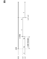
- the traffic jam information by VICS when driving on a highway (the thick line part in the figure is the traffic jam occurrence section), the traffic jam information by the vehicle speed sensor and the DCM, the section where the automatic driving level 2 can respond, and the section.
- the section that can be handled at the automatic operation level 3 is schematically shown.
- the English letters in FIG. 2 indicate the traveling positions A, Ba, Bb, C, D, and E with the passage of time in order.
- the HCU 160 acquires information from the VICS from the in-vehicle communication device 50 and determines whether or not there is a traffic jam at the travel destination (the front side of the vehicle) (execution of the first algorithm). That is, in the HCU 160, for example, the vehicle speed (traveling speed) of another vehicle on the front side traveling on the highway is lower than a predetermined first threshold value (for example, 40 km / h) based on the VICS information. In that case, it is determined that there is a traffic jam (first information). From this traffic jam information, the HCU 160 can grasp the occurrence point and the end point of the traffic jam at the travel destination.
- a predetermined first threshold value for example, 40 km / h
- the HCU 160 acquires information from the vehicle speed sensor and the DCM from the vehicle-mounted sensor 81 and the vehicle-mounted communication device 50, and determines whether or not there is a traffic jam at the travel destination (the front side of the vehicle) (execution of the second algorithm). That is, in the HCU 160, in the information obtained by the vehicle speed sensor or the DCM, for example, the vehicle speed (traveling speed) of the own vehicle traveling on the highway or another vehicle on the front side is a predetermined second threshold value (for example, 10 km). If it is less than / h), it is judged that there is a traffic jam (second information). The occurrence of the traffic jam corresponding to the second information indicates an area that permits (allows) the correspondence of the automatic driving level 3 at the time of the traffic jam traveling on the highway.
- the HCU 160 integrates the first information indicating the occurrence of traffic congestion and the second information to grasp the occurrence status of traffic congestion, and presents information to the driver (on the display unit) as described below. Display).
- the HCU 160 controls the display state in the display unit.
- the display unit will be described here assuming that the meter display 120 is used.
- the HCU 160 displays, for example, a vehicle speed value (80 km / h in FIG. 5) in the upper center of the meter display 120, and a lane (here, two lanes) below the vehicle speed value.
- the own vehicle and the preceding vehicle in the lane are displayed in real time.
- the HCU 160 provides information to be presented to the driver (“There is traffic jam in the future” in Fig. 5) according to the occurrence of traffic jams, such as the vehicle speed value, own vehicle, and the preceding vehicle. Display in an area that does not interfere with the display of the car.
- the HCU 160 obtains information on the occurrence of traffic congestion from VICS, it displays, for example, "There is traffic congestion in the future" on the meter display 120, and notifies the driver of the occurrence of traffic congestion.
- the automatic operation level is level 2.
- step S100 when the vehicle enters the congestion generation section based on VICS and the vehicle speed of the own vehicle based on the vehicle speed sensor is reduced, the HCU 160 changes the vehicle speed value display on the meter display 120 (for example, about 40 km / h). ), In addition, "Entered the traffic jam area" is displayed (notify the driver). However, at this stage, the vehicle speed is a traveling speed (40 km / h) indicating congestion in VICS, and does not satisfy the vehicle speed condition (for example, a condition below 10 km / h) that permits automatic driving level 3 during congestion. Therefore, level 2 is maintained as the automatic operation level.
- the vehicle speed is a traveling speed (40 km / h) indicating congestion in VICS, and does not satisfy the vehicle speed condition (for example, a condition below 10 km / h) that permits automatic driving level 3 during congestion. Therefore, level 2 is maintained as the automatic operation level.
- the HCU 160 also displays "Transition to automatic driving level 3 is not possible" on the meter display 120 so that the driver does not feel uncomfortable.
- the driver's discomfort is that the VICS information indicates that the vehicle is in a traffic jam section, but the automatic driving level at the time of traffic jam has not shifted to level 3.
- the traffic congestion occurrence information may be obtained by an in-vehicle sensor 81 using a sensor, a camera, or the like, instead of the information based on VICS.
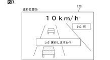
- step S120 when the vehicle enters the congestion generation section based on VICS and the vehicle speed of the own vehicle based on the vehicle speed sensor is further reduced, the HCU 160 changes the vehicle speed value display on the meter display 120 (for example,). 10km / h).
- the HCU 160 displays the meter display 120 indicating that "the transition to the automatic driving level 3 is possible”.
- the HCU 160 displays the meter display 120 indicating that "the transition to the automatic driving level 3 is possible".
- the driver performs an input operation to the operation device 150 (steer switch, operation lever, etc.) to execute the automatic driving level 3 at the time of traffic jam (the main driver shifts from the driver to the automatic driving system). Will be).
- the HCU 160 displays "cannot shift to the automatic operation level 3" on the meter display 120 while the condition for shifting to the automatic operation level 3 is not satisfied.
- “Transition to automatic operation level 3 is possible” is displayed, and when the driver performs an input operation to the operation device 150 for migration, the automatic operation level is displayed. 3 may be executed.
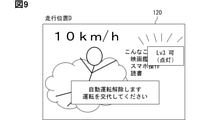
- the HCU 160 displays on the meter display 120 corresponding to the automatic operation level 3 in step S150.
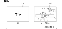
- the HCU 160 displays, for example, an image of a relaxed person and displays a second task allowed by the driver while the autonomous driving level 3 is being executed.
- the second task is, for example, watching a movie, watching TV, operating a smartphone, reading a book, or the like.
- step S160 when the vehicle speed values of the own vehicle and the preceding vehicle are increasing from the information based on the vehicle speed sensor and DCM and the traffic congestion situation begins to be alleviated, in step S170, the HCU 160 is, for example, "automatic".
- the display "Available for driving level 3" is blinked to indicate that the section where automatic driving level 3 is permitted due to traffic congestion is about to be removed.
- the HCU 160 displays "Cancel automatic operation. Please change operation” and shifts from the automatic operation mode to the driver operation mode. When the driver performs an input operation for transition to the operation device 150, the driver shifts to the automatic operation level 2.
- step S180 Displays at the traveling position E (FIGS. 2 and 10)
- step S190 even if the congestion has not ended
- step S200 Displays the vehicle speed value, the image of the own vehicle and the preceding vehicle on the meter display 120, and displays "automatic driving level 3 not possible”.
- step S200 the process returns to step S120.
- step S210 the HCU 160 shifts to the evacuation run and ends this control flow.
- the driver does not change driving, for example, the driver may be dozing or suddenly ill, and the HCU 160 safely stops the vehicle on the shoulder or the like as an evacuation run.
- step S190 the information by VICS is "no congestion"
- step S220 the process proceeds to step S200, and the HCU 160 determines. Continue to display "Automatic operation level 3 not possible”. Further, if a negative determination is made in step S220, the HCU 160 ends this control flow.
- the HCU 160 of the congestion determination device 100 and the display control device 101 includes the first information (congestion information by VICS) acquired by the vehicle-mounted communication device 50, the vehicle-mounted communication device 50, and the vehicle-mounted sensor.
- the second information traffic jam information by DCM and vehicle speed sensor acquired by 81, the judgment of the occurrence of traffic jam by the first algorithm and the judgment of the occurrence of traffic jam by the second algorithm are performed. There is. This makes it possible to accurately determine the occurrence of traffic congestion.
- the HCU 160 determines whether or not the display in which automatic operation is not possible is set to the meter display (display unit) 120 based on the result of the first algorithm and the result of the second algorithm. As a result, it is possible to clearly indicate to the driver that automatic driving is not possible.
- the HCU 160 displays that automatic operation is not possible when the first threshold value is satisfied by the first algorithm and the second threshold value is not satisfied by the second algorithm. As a result, even if it is found from the first information that congestion has occurred, the HCU 160 cannot automatically operate the display unit 120 unless the second threshold value is satisfied based on the second information. By displaying the fact, the user can be clearly informed that the automatic operation cannot be started yet. In other words, it is possible to inform the user in an easy-to-understand manner about the shift to automatic driving.
- the HCU 160 displays that the automatic driving is not possible if the occurrence of the traffic jam based on the first information is not finished after the automatic driving is finished. As a result, the display to the driver is not frequently switched between "automatic driving possible” and “automatic driving impossible", and the driver is not bothered.
- the HCU 160 continues to display that automatic driving is not possible if there is a traffic jam based on the first information again in the future even if there is no traffic jam based on the first information.
- the display to the driver is not frequently switched between "automatic driving possible” and “automatic driving impossible", and the driver is not bothered.
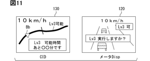
- FIGS. 11 and 12 The display form in the second embodiment is shown in FIGS. 11 and 12.
- the CID 130 or HUD 110 is also possible
- the meter display 120 which is the main display unit.
- 11 and 12 show, for example, a state (traveling position Bb) in which the vehicle is traveling on a highway and is about to shift to the automatic driving level 3 (FIG. 7 of the first embodiment).
- FIG. 11 shows a case where the display content on the meter display 120 and the display content on the CID 130 are different.
- the display contents may be the same for the meter display 120 and the CID 130.
- the driver can eliminate the omission of grasping the information and further monitor the surroundings according to the automatic driving level. It is possible to surely grasp the distinction between necessary and unnecessary.
- the third embodiment is a modification of the conditions for starting automatic operation.
- the HCU 160 further acquires third information different from the second information (vehicle speed value) as a condition for starting automatic driving from the peripheral monitoring sensor 40 as an acquisition unit and the locator 30.
- the third information is, for example, the center of the driving road where the traveling lane (lane) is two or more lanes, there are other vehicles around the own vehicle (the same lane and the adjacent lane). Information such as the median strip in the area and the possession of high-precision map data.
- the HCU 160 When the HCU 160 satisfies the first threshold value (traffic jam information by VICS) and the second threshold value (vehicle speed value by the vehicle speed sensor) and also satisfies the third information, the HCU 160 automatically displays the display unit. Display that driving is possible, or display the start of automatic driving. As a result, it is possible to improve the reliability in grasping the occurrence situation of the traffic jam.
- VICS traffic jam information by VICS
- vehicle speed value by the vehicle speed sensor vehicle speed value by the vehicle speed sensor
- the fourth embodiment further changes the conditions for starting the automatic operation.
- the HCU 160 further acquires the fourth information, which is the start condition of the automatic operation, not limited to the time of traffic jam, from the peripheral monitoring sensor 40 as the acquisition unit.
- the fourth information is information indicating possible sections such as constant speed running, following running, and LTA (lane keeping running) without traffic congestion on a highway, as described above.
- the HCU 160 When the HCU 160 is in the state indicated by the fourth information, the HCU 160 displays on the display unit that automatic operation is possible regardless of the first and second information. As a result, it is possible to present the driver with a wide range of transitions to automatic driving, not limited to automatic driving when traffic jams occur.
- one of the plurality of display devices (CID130) is shown in FIGS. 13 and 14. You may display a TV or a movie like this.
- Disclosure in this specification, drawings, etc. is not limited to the exemplified embodiments. Disclosures include exemplary embodiments and modifications by those skilled in the art based on them. For example, the disclosure is not limited to the parts and / or combinations of elements shown in the embodiments. Disclosure can be carried out in various combinations. The disclosure can have additional parts that can be added to the embodiment. Disclosures include those in which the parts and / or elements of the embodiment are omitted. Disclosures include the replacement or combination of parts and / or elements between one embodiment and another. The technical scope disclosed is not limited to the description of the embodiments. Some technical scopes disclosed are indicated by the claims description and should be understood to include all modifications within the meaning and scope equivalent to the claims description.
- the controls and techniques described herein are by means of a processor programmed to perform one or more functions embodied by a computer program, and a dedicated computer provided by configuring memory. I made it happen.
- control unit and its method described in the present disclosure may be realized by a dedicated computer provided by configuring a processor with one or more dedicated hardware logic circuits.
- controls and methods described herein are a combination of a processor and memory programmed to perform one or more functions and a processor configured by one or more hardware logic circuits. It may be realized by one or more dedicated computers configured by.
- the computer program may be stored in a computer-readable non-transition tangible recording medium as an instruction executed by the computer.
Landscapes
- Engineering & Computer Science (AREA)
- Transportation (AREA)
- Mechanical Engineering (AREA)
- Automation & Control Theory (AREA)
- Physics & Mathematics (AREA)
- General Physics & Mathematics (AREA)
- Human Computer Interaction (AREA)
- Life Sciences & Earth Sciences (AREA)
- Atmospheric Sciences (AREA)
- Chemical & Material Sciences (AREA)
- Combustion & Propulsion (AREA)
- Analytical Chemistry (AREA)
- Traffic Control Systems (AREA)
- Control Of Driving Devices And Active Controlling Of Vehicle (AREA)
Abstract
L'invention concerne un dispositif de détermination de congestion de véhicule, dans lequel une unité HCU (160) intègre des premières informations indiquant l'apparition d'une congestion sur la base d'une première valeur de seuil avec des secondes informations indiquant l'apparition d'une congestion sur la base d'une seconde valeur de seuil, et exécute un premier algorithme pour déterminer l'apparition d'une congestion en utilisant la première valeur de seuil et un second algorithme pour déterminer l'apparition d'une congestion en utilisant la seconde valeur de seuil. L'invention concerne également un dispositif de commande d'affichage de véhicule dans lequel, lorsque la première valeur de seuil est satisfaite dans les premières informations et la seconde valeur de seuil n'est pas satisfaite dans les secondes informations, l'unité HCU (160) amène une unité d'affichage à afficher une indication précisant qu'une conduite automatique est impossible.
Priority Applications (1)
| Application Number | Priority Date | Filing Date | Title |
|---|---|---|---|
| US18/159,369 US20230166754A1 (en) | 2020-08-21 | 2023-01-25 | Vehicle congestion determination device and vehicle display control device |
Applications Claiming Priority (2)
| Application Number | Priority Date | Filing Date | Title |
|---|---|---|---|
| JP2020-140156 | 2020-08-21 | ||
| JP2020140156A JP7384126B2 (ja) | 2020-08-21 | 2020-08-21 | 車両用渋滞判断装置、および車両用表示制御装置 |
Related Child Applications (1)
| Application Number | Title | Priority Date | Filing Date |
|---|---|---|---|
| US18/159,369 Continuation US20230166754A1 (en) | 2020-08-21 | 2023-01-25 | Vehicle congestion determination device and vehicle display control device |
Publications (1)
| Publication Number | Publication Date |
|---|---|
| WO2022039021A1 true WO2022039021A1 (fr) | 2022-02-24 |
Family
ID=80322645
Family Applications (1)
| Application Number | Title | Priority Date | Filing Date |
|---|---|---|---|
| PCT/JP2021/028826 WO2022039021A1 (fr) | 2020-08-21 | 2021-08-03 | Dispositif de détermination de congestion de véhicule et dispositif de commande d'affichage de véhicule |
Country Status (3)
| Country | Link |
|---|---|
| US (1) | US20230166754A1 (fr) |
| JP (2) | JP7384126B2 (fr) |
| WO (1) | WO2022039021A1 (fr) |
Citations (2)
| Publication number | Priority date | Publication date | Assignee | Title |
|---|---|---|---|---|
| JP2005324661A (ja) * | 2004-05-13 | 2005-11-24 | Aisin Aw Co Ltd | 車両制御装置 |
| JP2019212071A (ja) * | 2018-06-06 | 2019-12-12 | クラリオン株式会社 | 運転支援装置及び運転支援システム |
Family Cites Families (2)
| Publication number | Priority date | Publication date | Assignee | Title |
|---|---|---|---|---|
| JP2017142079A (ja) | 2016-02-08 | 2017-08-17 | 三菱電機株式会社 | 渋滞回避システム、サーバ、情報端末装置及びプログラム |
| JP2019036012A (ja) | 2017-08-10 | 2019-03-07 | トヨタ自動車株式会社 | 情報通知装置、情報通知システム、情報通知方法、情報通知プログラム |
-
2020
- 2020-08-21 JP JP2020140156A patent/JP7384126B2/ja active Active
-
2021
- 2021-08-03 WO PCT/JP2021/028826 patent/WO2022039021A1/fr active Application Filing
-
2023
- 2023-01-25 US US18/159,369 patent/US20230166754A1/en active Pending
- 2023-11-07 JP JP2023190332A patent/JP2024014908A/ja active Pending
Patent Citations (2)
| Publication number | Priority date | Publication date | Assignee | Title |
|---|---|---|---|---|
| JP2005324661A (ja) * | 2004-05-13 | 2005-11-24 | Aisin Aw Co Ltd | 車両制御装置 |
| JP2019212071A (ja) * | 2018-06-06 | 2019-12-12 | クラリオン株式会社 | 運転支援装置及び運転支援システム |
Also Published As
| Publication number | Publication date |
|---|---|
| US20230166754A1 (en) | 2023-06-01 |
| JP2022035668A (ja) | 2022-03-04 |
| JP2024014908A (ja) | 2024-02-01 |
| JP7384126B2 (ja) | 2023-11-21 |
Similar Documents
| Publication | Publication Date | Title |
|---|---|---|
| US20200377126A1 (en) | Information output control device and information output control method | |
| WO2022044768A1 (fr) | Dispositif d'affichage de véhicule | |
| US20230182572A1 (en) | Vehicle display apparatus | |
| US20230013492A1 (en) | Presentation control device and non-transitory computer readable storage medium | |
| US20240043031A1 (en) | Presentation control device, autonomous driving control device, and storage mediums | |
| JP7363833B2 (ja) | 提示制御装置、提示制御プログラム、自動走行制御システムおよび自動走行制御プログラム | |
| JP7424327B2 (ja) | 車両用表示制御装置、車両用表示制御システム、及び車両用表示制御方法 | |
| JP7355057B2 (ja) | 車両用制御装置及び車両用制御方法 | |
| WO2022039021A1 (fr) | Dispositif de détermination de congestion de véhicule et dispositif de commande d'affichage de véhicule | |
| JP2021160707A (ja) | 提示制御装置および提示制御プログラム | |
| WO2022030317A1 (fr) | Dispositif d'affichage de véhicule et procédé d'affichage de véhicule | |
| JP7327426B2 (ja) | 車両用表示装置、および表示方法 | |
| WO2021199964A1 (fr) | Dispositif de commande de présentation, programme de commande de présentation, système de commande de conduite automatisée et procédé de commande de conduite automatisée | |
| WO2022107466A1 (fr) | Dispositif de commande de véhicule et dispositif de notification de véhicule | |
| JP7310851B2 (ja) | 車両用表示装置 | |
| US20230019934A1 (en) | Presentation control apparatus | |
| WO2023085064A1 (fr) | Dispositif de commande de véhicule | |
| US20240010221A1 (en) | Vehicle presentation control device, vehicle presentation control system, and vehicle presentation control method | |
| JP7484689B2 (ja) | 制御システム、制御装置および制御プログラム | |
| WO2022030372A1 (fr) | Dispositif de commande d'affichage de véhicule, système de commande d'affichage de véhicule et procédé de commande d'affichage de véhicule | |
| JP2022080260A (ja) | 車両制御装置、および車両用報知装置 | |
| JP2022036003A (ja) | 車両用表示装置 | |
| JP2023073198A (ja) | 車両制御装置 | |
| JP2021163467A (ja) | 提示制御装置および提示制御プログラム |
Legal Events
| Date | Code | Title | Description |
|---|---|---|---|
| 121 | Ep: the epo has been informed by wipo that ep was designated in this application |
Ref document number: 21858169 Country of ref document: EP Kind code of ref document: A1 |
|
| NENP | Non-entry into the national phase |
Ref country code: DE |
|
| 122 | Ep: pct application non-entry in european phase |
Ref document number: 21858169 Country of ref document: EP Kind code of ref document: A1 |