WO2022030554A1 - フレキシブル超音波発生装置 - Google Patents
フレキシブル超音波発生装置 Download PDFInfo
- Publication number
- WO2022030554A1 WO2022030554A1 PCT/JP2021/028975 JP2021028975W WO2022030554A1 WO 2022030554 A1 WO2022030554 A1 WO 2022030554A1 JP 2021028975 W JP2021028975 W JP 2021028975W WO 2022030554 A1 WO2022030554 A1 WO 2022030554A1
- Authority
- WO
- WIPO (PCT)
- Prior art keywords
- flexible
- ultrasonic generator
- actuator
- flexible ultrasonic
- drive circuit
- Prior art date
- Legal status (The legal status is an assumption and is not a legal conclusion. Google has not performed a legal analysis and makes no representation as to the accuracy of the status listed.)
- Ceased
Links
Images



Classifications
-
- A—HUMAN NECESSITIES
- A61—MEDICAL OR VETERINARY SCIENCE; HYGIENE
- A61B—DIAGNOSIS; SURGERY; IDENTIFICATION
- A61B17/00—Surgical instruments, devices or methods
- A61B17/32—Surgical cutting instruments
- A61B17/320068—Surgical cutting instruments using mechanical vibrations, e.g. ultrasonic
- A61B17/320092—Surgical cutting instruments using mechanical vibrations, e.g. ultrasonic with additional movable means for clamping or cutting tissue, e.g. with a pivoting jaw
-
- A—HUMAN NECESSITIES
- A61—MEDICAL OR VETERINARY SCIENCE; HYGIENE
- A61B—DIAGNOSIS; SURGERY; IDENTIFICATION
- A61B17/00—Surgical instruments, devices or methods
- A61B17/32—Surgical cutting instruments
- A61B17/320068—Surgical cutting instruments using mechanical vibrations, e.g. ultrasonic
-
- A—HUMAN NECESSITIES
- A61—MEDICAL OR VETERINARY SCIENCE; HYGIENE
- A61B—DIAGNOSIS; SURGERY; IDENTIFICATION
- A61B17/00—Surgical instruments, devices or methods
- A61B17/22—Implements for squeezing-off ulcers or the like on inner organs of the body; Implements for scraping-out cavities of body organs, e.g. bones; for invasive removal or destruction of calculus using mechanical vibrations; for removing obstructions in blood vessels, not otherwise provided for
- A61B17/22004—Implements for squeezing-off ulcers or the like on inner organs of the body; Implements for scraping-out cavities of body organs, e.g. bones; for invasive removal or destruction of calculus using mechanical vibrations; for removing obstructions in blood vessels, not otherwise provided for using mechanical vibrations, e.g. ultrasonic shock waves
- A61B17/22012—Implements for squeezing-off ulcers or the like on inner organs of the body; Implements for scraping-out cavities of body organs, e.g. bones; for invasive removal or destruction of calculus using mechanical vibrations; for removing obstructions in blood vessels, not otherwise provided for using mechanical vibrations, e.g. ultrasonic shock waves in direct contact with, or very close to, the obstruction or concrement
- A61B17/2202—Implements for squeezing-off ulcers or the like on inner organs of the body; Implements for scraping-out cavities of body organs, e.g. bones; for invasive removal or destruction of calculus using mechanical vibrations; for removing obstructions in blood vessels, not otherwise provided for using mechanical vibrations, e.g. ultrasonic shock waves in direct contact with, or very close to, the obstruction or concrement the ultrasound transducer being inside patient's body at the distal end of the catheter
-
- A—HUMAN NECESSITIES
- A61—MEDICAL OR VETERINARY SCIENCE; HYGIENE
- A61B—DIAGNOSIS; SURGERY; IDENTIFICATION
- A61B17/00—Surgical instruments, devices or methods
- A61B17/32—Surgical cutting instruments
- A61B17/320016—Endoscopic cutting instruments, e.g. arthroscopes, resectoscopes
-
- A—HUMAN NECESSITIES
- A61—MEDICAL OR VETERINARY SCIENCE; HYGIENE
- A61B—DIAGNOSIS; SURGERY; IDENTIFICATION
- A61B17/00—Surgical instruments, devices or methods
- A61B17/22—Implements for squeezing-off ulcers or the like on inner organs of the body; Implements for scraping-out cavities of body organs, e.g. bones; for invasive removal or destruction of calculus using mechanical vibrations; for removing obstructions in blood vessels, not otherwise provided for
- A61B17/22004—Implements for squeezing-off ulcers or the like on inner organs of the body; Implements for scraping-out cavities of body organs, e.g. bones; for invasive removal or destruction of calculus using mechanical vibrations; for removing obstructions in blood vessels, not otherwise provided for using mechanical vibrations, e.g. ultrasonic shock waves
- A61B17/22012—Implements for squeezing-off ulcers or the like on inner organs of the body; Implements for scraping-out cavities of body organs, e.g. bones; for invasive removal or destruction of calculus using mechanical vibrations; for removing obstructions in blood vessels, not otherwise provided for using mechanical vibrations, e.g. ultrasonic shock waves in direct contact with, or very close to, the obstruction or concrement
- A61B17/2202—Implements for squeezing-off ulcers or the like on inner organs of the body; Implements for scraping-out cavities of body organs, e.g. bones; for invasive removal or destruction of calculus using mechanical vibrations; for removing obstructions in blood vessels, not otherwise provided for using mechanical vibrations, e.g. ultrasonic shock waves in direct contact with, or very close to, the obstruction or concrement the ultrasound transducer being inside patient's body at the distal end of the catheter
- A61B2017/22021—Implements for squeezing-off ulcers or the like on inner organs of the body; Implements for scraping-out cavities of body organs, e.g. bones; for invasive removal or destruction of calculus using mechanical vibrations; for removing obstructions in blood vessels, not otherwise provided for using mechanical vibrations, e.g. ultrasonic shock waves in direct contact with, or very close to, the obstruction or concrement the ultrasound transducer being inside patient's body at the distal end of the catheter electric leads passing through the catheter
-
- A—HUMAN NECESSITIES
- A61—MEDICAL OR VETERINARY SCIENCE; HYGIENE
- A61B—DIAGNOSIS; SURGERY; IDENTIFICATION
- A61B17/00—Surgical instruments, devices or methods
- A61B17/22—Implements for squeezing-off ulcers or the like on inner organs of the body; Implements for scraping-out cavities of body organs, e.g. bones; for invasive removal or destruction of calculus using mechanical vibrations; for removing obstructions in blood vessels, not otherwise provided for
- A61B17/22004—Implements for squeezing-off ulcers or the like on inner organs of the body; Implements for scraping-out cavities of body organs, e.g. bones; for invasive removal or destruction of calculus using mechanical vibrations; for removing obstructions in blood vessels, not otherwise provided for using mechanical vibrations, e.g. ultrasonic shock waves
- A61B2017/22027—Features of transducers
-
- A—HUMAN NECESSITIES
- A61—MEDICAL OR VETERINARY SCIENCE; HYGIENE
- A61B—DIAGNOSIS; SURGERY; IDENTIFICATION
- A61B17/00—Surgical instruments, devices or methods
- A61B17/32—Surgical cutting instruments
- A61B17/320068—Surgical cutting instruments using mechanical vibrations, e.g. ultrasonic
- A61B2017/320071—Surgical cutting instruments using mechanical vibrations, e.g. ultrasonic with articulating means for working tip
-
- A—HUMAN NECESSITIES
- A61—MEDICAL OR VETERINARY SCIENCE; HYGIENE
- A61B—DIAGNOSIS; SURGERY; IDENTIFICATION
- A61B17/00—Surgical instruments, devices or methods
- A61B17/32—Surgical cutting instruments
- A61B17/320068—Surgical cutting instruments using mechanical vibrations, e.g. ultrasonic
- A61B2017/320072—Working tips with special features, e.g. extending parts
- A61B2017/320074—Working tips with special features, e.g. extending parts blade
Definitions
- the present invention relates to a flexible ultrasonic generator.
- the endoscope can be treated with various forceps by inserting various forceps from the entrance and projecting the endoscope from the tip surface of the endoscope.
- an ultrasonic scalpel that performs a surgical operation using ultrasonic vibration is also known (see, for example, Patent Document 1).
- This ultrasonic scalpel is provided so that the tip portion (the root of the scalpel portion) can be bent.
- the present invention has been made in view of such a background, and an object of the present invention is to provide an ultrasonic wave generator capable of improving operability when performing surgery.
- the flexible ultrasonic generator of the present invention is a bendable flexible ultrasonic generator, which includes an actuator for generating ultrasonic waves, a flexible substrate, and a plurality of electronic components mounted on the flexible substrate. However, it is characterized by including a drive circuit for driving the actuator.
- the flexible ultrasonic generator of the present invention since the plurality of electronic components constituting the drive circuit are mounted on the flexible substrate and the drive circuit is bendable, the flexible ultrasonic generator that can be bent is configured. Can be done. This makes it possible to improve the operability when performing surgery using the flexible ultrasonic generator.
- the drive circuit generates a voltage in a pulse shape.
- ultrasonic waves can be reliably and stably generated.
- the drive circuit includes an inductor, a field effect transistor on the input side, a field effect transistor on the output side, a Schottky barrier diode, and a discharge resistor, and the inductor has a field effect on the input side. It is preferable that the transistor, the Schottky barrier diode, the field effect transistor on the output side, and the discharge resistor are arranged in this order.
- ultrasonic waves can be reliably generated while the drive circuit is compact and bendable.
- the actuator vibrates ultrasonically.
- the actuator is provided with a flexible tube into which the actuator and the drive circuit are inserted, and a treatment tool is attached to the actuator.
- the ultrasonic generator since the ultrasonic generator is bendable, even when the ultrasonic generator is inserted into the body, the ultrasonic generator can be curved along the curvature in the body, and a treatment tool is used. Can be operated on.
- the actuator is provided with a flexible tube into which the drive circuit is inserted, and the flexible tube is inserted through the inside of the endoscope from the forceps inlet of the endoscope and is inserted into the actuator.
- the ultrasonic generator since the ultrasonic generator is bendable, even when the ultrasonic generator is inserted into the endoscope, the ultrasonic generator can be curved following the curvature of the endoscope. , The operation can be performed using the ultrasonic generator inserted in the endoscope.
- the perspective view which shows the flexible ultrasonic wave generator The perspective view which shows the flexible ultrasonic wave generator.
- Circuit diagram of flexible ultrasonic generator The perspective view which shows the state which attached the active blade to the flexible ultrasonic generator.
- the flexible ultrasonic generator 2 is inserted into, for example, a transparent flexible tube 10 having flexibility with a small diameter (for example, a diameter of 3 mm), and various electronic components are mounted on the first to third flexible substrates 11 to 13.
- An actuator 14 is connected to the tip of the flexible ultrasonic generator 2 (the tip of the third flexible substrate 13).
- the actuator 14 is composed of, for example, a ceramic piezoelectric element such as PZT.
- a plurality of inductors 15 are mounted on the first and second flexible boards 11 and 12, and the first flexible board 11 and the second flexible board 12 are connected by wires.
- a discharge resistor 21, a FET (Field Effect Transistor) 22, and an SBD (Schottky diode) 23 are mounted on the third flexible substrate 13.
- the FET 22 on the inductor 15 side of the SBD 23 is the FET 22 on the input side
- the FET 22 on the discharge resistance 21 side of the SBD 23 is the FET 22 on the output side.
- the electronic components 15, 21 to 23 constituting the drive circuit 25 are mounted on the first to third flexible boards 11 to 13.
- the SBD23 is a unipolar device that obtains rectifying characteristics by Schottky junction in which a metal and a semiconductor are brought into contact with each other. Therefore, when a forward voltage is applied from the outside, the SBD 23 has a characteristic that the energy barrier seen from the semiconductor side becomes smaller and electrons flow from the n-type semiconductor to the metal over the lowered barrier.
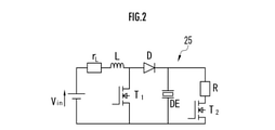
- FIG. 2 is a circuit diagram showing a flexible ultrasonic generator 2, in which the inductors 15 are r L and L, T1 is the FET 22 on the input side, T2 is the FET 22 on the output side, D is the SBD 23, and R is the discharge resistance 21.
- the actuator 14 is regarded as a capacitor by DE.
- Laparoscopic examination is well known and its detailed description is simplified.
- a small hole for example, 5 mm to 12 mm
- a tubular device called a port is inserted through the hole, and then carbon dioxide is sent from the port to inflate the abdomen. Make it easier to observe the inside of the stomach.
- a laparoscope is inserted into the abdomen from the port to display organs such as the stomach, large intestine, and gallbladder on a monitor for examination. If this test finds an affected area that requires treatment, the laparoscope is removed.
- a treatment tool suitable for treating the affected area for example, an active blade 30 (treatment tool) is attached to the actuator 14 of the flexible ultrasonic generator 2, and the vicinity of the affected area in the body via the port. Insert up to. At this time, the active blade 30 may be inserted in a state of being housed in the flexible tube 10.
- an active blade 30 treatment tool
- a voltage is applied to the flexible ultrasonic generator 2 and the actuator 14 is vibrated by the drive circuit 25.
- the vibration of the actuator 14 causes the active blade 30 to vibrate, and the affected area can be treated by ultrasonic vibration.
- it is configured to vibrate with ultrasonic waves of, for example, 20 kHz or more.
- the flexible ultrasonic generator 2 is removed from the body.
- the flexible ultrasonic generator 2 is inserted in the flexible tube 10, and the electronic components 15, 21 to 23 constituting the drive circuit 25 are mounted on the first to third flexible substrates 11 to 13. It has been implemented. Thereby, the flexible ultrasonic wave generator 2 can be configured to be bendable, and the flexible ultrasonic wave generator 2 can be bent according to the curved shape in the body.
- the drive circuit 25 is composed of the inductor 15, the discharge resistor 21, the FET 22, and the SBD 23, it is possible to obtain a driving force for ultrasonically vibrating the actuator 14 while being bendable. Further, since the drive circuit 25 generates a voltage in a pulse shape, the actuator 14 can be reliably ultrasonically vibrated.
- the flexible tube 10 in front of the drive circuit 25 has a low voltage and is highly safe.
- the flexible ultrasonic generator 2 can also be used by inserting it into the endoscope 51.
- the endoscope system 50 is connected to the endoscope 51, the flexible ultrasonic generator 2 inserted into the endoscope 51, and the endoscope 51, and is inside. It includes a light source device 53 that sends light to the endoscope 51, and a control device 54.
- the light source device 53 includes a well-known air supply / liquid supply device (not shown) that sends gas (air, gas, etc.) and liquid (washing water, etc.) to the endoscope 51.
- the endoscope 51 is well-known and simplifies its detailed description, but includes an insertion portion 56 to be inserted into the body and an operation portion 57 connected to the root portion of the insertion portion 56. There is.
- the insertion portion 56 includes a tip portion 56a and a bending portion 56b configured to be bendable.
- a camera for photographing the inside of the body is built in the tip portion 56a.
- An objective lens 61 for camera photography, a nozzle 62, a forceps outlet 63, and a light guide 64 that illuminates the surgical field by irradiating light from a light source device 53 are provided on the tip surface of the tip portion 56a. ..
- a control device 54 that comprehensively controls the operation of the endoscope system 50 is connected to the light source device 53.
- the control device 54 controls the drive of the camera via a connection cable (not shown) passed through the inside of the endoscope 51.
- the captured image data captured by the camera is sent to the control device 54 via the connection cable and displayed on a display (not shown).
- the operation unit 57 is provided with a forceps inlet 71, an operation button 72 operated when air supply and liquid supply are performed, and a bending operation knob 73.
- the bending operation knob 73 is operated, the wire inserted in the insertion portion 56 is pushed and pulled, so that the bending portion 56b of the insertion portion 56 bends in the vertical and horizontal directions. As a result, the tip portion 56a is directed in the desired direction in the body.
- gas and liquid are sent to the nozzle 62 provided on the tip surface of the insertion portion 56 via a pipe line (not shown) provided inside the endoscope 51.
- the nozzle 62 ejects gas and liquid toward the tip surface of the endoscope 51.
- the forceps inlet 71 is communicated with the forceps outlet 63 provided on the tip surface of the insertion portion 56 via a forceps duct (not shown) provided inside the endoscope 51.
- a forceps duct (not shown) provided inside the endoscope 51.
- the insertion portion 56 is inserted through the anus into the body, for example, into the intestinal tract.
- the light from the light source device 53 is emitted to the front of the insertion portion 56 of the endoscope 51 through a cable or the like.
- the captured image data captured by the camera provided at the tip portion 56a of the insertion portion 56 is sent to the control device 54 via the connection cable and displayed on the display.
- a treatment tool suitable for treating the affected area for example, a flexible flexible ultrasonic generator 2 having an active blade 30 (endoscopic treatment tool) attached to an actuator 14. Is inserted into the forceps inlet 71 of the endoscope 51, and the active blade 30 is projected from the forceps outlet 63.
- a voltage is applied to the flexible ultrasonic generator 2 and the actuator 14 is vibrated by the drive circuit 25.
- the vibration of the actuator 14 causes the active blade 30 to vibrate, and the affected area can be treated by ultrasonic vibration.
- it is configured to vibrate with ultrasonic waves of, for example, 20 kHz or more.
- the insertion portion 56 is removed from the body.
- the flexible ultrasonic generator 2 is inserted in the flexible tube 10, and the electronic components 55, 61 to 63 are mounted on the first to third flexible substrates 11 to 13.
- the flexible ultrasonic generator 2 can be configured to be bendable, and when the curved portion 56b of the insertion portion 56 is curved, the first to third flexible substrates 11 to 13 are curved accordingly.
- the flexible ultrasonic generator 2 can be curved.
- the active blade 30 is attached to the actuator 14, various treatment tools can be attached.
- the actuator 14 is not limited to the piezoelectric element made of ceramic, and may be made of, for example, a dielectric elastomer containing a silicon resin or the like, or may be one that does not vibrate ultrasonically.
Landscapes
- Health & Medical Sciences (AREA)
- Surgery (AREA)
- Life Sciences & Earth Sciences (AREA)
- Engineering & Computer Science (AREA)
- Molecular Biology (AREA)
- Animal Behavior & Ethology (AREA)
- Veterinary Medicine (AREA)
- Biomedical Technology (AREA)
- Heart & Thoracic Surgery (AREA)
- Medical Informatics (AREA)
- Public Health (AREA)
- Nuclear Medicine, Radiotherapy & Molecular Imaging (AREA)
- General Health & Medical Sciences (AREA)
- Mechanical Engineering (AREA)
- Dentistry (AREA)
- Orthopedic Medicine & Surgery (AREA)
- Vascular Medicine (AREA)
- Surgical Instruments (AREA)
- Endoscopes (AREA)
- Ultra Sonic Daignosis Equipment (AREA)
Abstract
フレキシブルフレキシブル超音波発生装置2は、可撓性を有するフレキシブルチューブ10内に挿入されており、第1~第3フレキシブル基板11~13に、駆動回路25を構成するインダクタ15、放電用抵抗21、FET22、SBD23が実装されている。フレキシブル超音波発生装置2の先端部には、アクチュエータ14が接続されている。アクチュエータ14には、アクティブブレード30が取り付けられている。
Description
本発明は、フレキシブル超音波発生装置に関する。
従来、湾曲自在な内視鏡を用いた手術が広く行われるようになっている。内視鏡は、各種鉗子を入口から挿入して、内視鏡の先端面から突出させることで、各種鉗子による処置を行うことができる。
また、超音波振動を利用して外科手術を行う超音波メスも知られている(例えば、特許文献1参照)。この超音波メスは、先端部(メス部分の根本)が屈曲可能に設けられている。
特許文献1に記載の超音波メスは、先端部しか屈曲させることができないため、メスを体内の所望の位置に挿入することができず、操作性が悪かった。
本発明はかかる背景に鑑みてなされたものであり、手術を行う場合の操作性を向上することができる超音波発生装置を提供することを目的とする。
[1]本発明のフレキシブル超音波発生装置は、屈曲可能なフレキシブル超音波発生装置であって、超音波を発生するアクチュエータと、フレキシブル基板と、前記フレキシブル基板に実装された複数の電子部品を有し、前記アクチュエータを駆動する駆動回路と、を備えることを特徴とする。
本発明のフレキシブル超音波発生装置によれば、駆動回路を構成する複数の電子部品は、フレキシブル基板に実装され、駆動回路は屈曲可能であるので、屈曲可能なフレキシブル超音波発生装置を構成することができる。これにより、フレキシブル超音波発生装置を用いて手術を行う場合の操作性を向上することができる。
[2]前記駆動回路は、パルス状に電圧を発生させることが好ましい。
上記構成によれば、確実に安定して超音波を発生させることができる。
[3]前記駆動回路は、インダクタと、入力側の電界効果トランジスタと、出力側の電界効果トランジスタと、ショットキーバリアダイオードと、放電用抵抗と、を備え、前記インダクタ、前記入力側の電界効果トランジスタ、前記 ショットキーバリアダイオード、前記出力側の電界効果トランジスタ、前記放電用抵抗の順に配置されていることが好ましい。
上記構成によれば、駆動回路を小型で湾曲可能に構成しながらも、確実に超音波を発生させることができる。
[4]前記アクチュエータは、超音波振動することが好ましい。
上記構成によれば、フレキシブル超音波発生装置を用いて超音波振動により手術を行う場合の操作性を向上することができる。
[5]前記アクチュエータと、前記駆動回路とが挿入される可撓性を有するフレキシブルチューブを備え、前記アクチュエータには、処置具が取り付けられることが好ましい。
上記構成によれば、超音波発生装置は屈曲可能であるので、超音波発生装置を体内に挿入した場合でも、体内の湾曲に沿って超音波発生装置を湾曲させることができ、処置具を用いて手術を行うことができる。
[6]前記アクチュエータと、前記駆動回路とが挿入される可撓性を有するフレキシブルチューブを備え、前記フレキシブルチューブは、内視鏡の鉗子入口から該内視鏡の内部を挿通され、前記アクチュエータには、内視鏡用処置具が取り付けられることが好ましい。
上記構成によれば、超音波発生装置は屈曲可能であるので、超音波発生装置を内視鏡に挿入した場合でも、内視鏡の湾曲に追従して超音波発生装置を湾曲させることができ、内視鏡に挿入された超音波発生装置を用いて手術を行うことができる。
以下、本発明の実施形態について、図面を参照しながら説明する。
先ず、本発明を実施したフレキシブル超音波発生装置2の一例について説明する。
フレキシブル超音波発生装置2は、小径(例えば、直径3mm)の可撓性を有する例えば透明なフレキシブルチューブ10内に挿入されており、第1~第3フレキシブル基板11~13に各種電子部品が実装されている。フレキシブル超音波発生装置2の先端部(第3フレキシブル基板13の先端部)には、アクチュエータ14が接続されている。本実施形態では、アクチュエータ14は、例えば、PZT等のセラミック製の圧電素子から構成されている。
本実施形態では、第1,第2フレキシブル基板11,12には、インダクタ15が複数実装され、第1フレキシブル基板11と、第2フレキシブル基板12とは、ワイヤ接続されている。
第3フレキシブル基板13には、放電用抵抗21と、FET(Field Effect Transistor:電界効果トランジスタ)22と、SBD(Schottky diode)23とが実装されている。
SBD23よりもインダクタ15側のFET22が入力側のFET22であり、SBD23よりも放電用抵抗21側のFET22が出力側のFET22である。駆動回路25(図2及び図3参照)を構成する各電子部品15,21~23は、第1~第3フレキシブル基板11~13に実装されている。
SBD23は、金属と半導体を接触させるショットキー接合により整流特性を得るユニポーラデバイスである。このため、SBD23は、外部より順方向電圧を印加すると、半導体側から見たエネルギー障壁が小さくなり、低くなった障壁を超えてn型半導体から金属のほうへ電子が流れる特性を有する。
図2は、フレキシブル超音波発生装置2を示す回路図であり、インダクタ15がrLとL、T1が入力側のFET22、T2が出力側のFET22、DがSBD23、Rが放電用抵抗21、DEがコンデンサと見立てたアクチュエータ14である。
次に上記構成のフレキシブル超音波発生装置2の作用について説明する。詳しくは、腹腔鏡(図示せず)を用いた検査後に、処置が必要な患部に対して、フレキシブル超音波発生装置2を用いて処置(手術)を行う場合について説明する。
先ず、腹腔鏡による検査について説明する。腹腔鏡による検査は、周知のものであり、その詳細な説明は簡略化する。該検査は、例えば、患者のお腹に、小さい穴(例えば、5mm~12mm)開けて、その穴からポートと称される筒状の器具を挿入したあと、ポートより二酸化炭素を送り込みお腹を膨らませてお腹の中を観察しやすくする。そして、ポートから腹腔鏡をお腹の中に挿入して胃、大腸、胆嚢などの臓器をモニターに映し出し、検査を行う。この検査で処置が必要な患部を発見した場合、腹腔鏡を抜き取る。
そして、図3に示すように、患部の処置に適した処置具、例えば、アクティブブレード30(処置具)を、フレキシブル超音波発生装置2のアクチュエータ14に取り付け、ポートを介して体内の患部の近傍まで挿入する。この際、アクティブブレード30をフレキシブルチューブ10内に収納した状態で挿入するようにしてもよい。
次に、フレキシブル超音波発生装置2に電圧を加え、駆動回路25によりアクチュエータ14を振動させる。アクチュエータ14の振動により、アクティブブレード30が振動されて、超音波振動により患部を処置することができる。本実施形態では、例えば20kHz以上の超音波で振動させるように構成されている。そして、患部の処置を行った後、フレキシブル超音波発生装置2を体内から抜き取る。
本実施形態では、フレキシブル超音波発生装置2は、フレキシブルチューブ10内に挿入されており、駆動回路25を構成する各電子部品15,21~23は、第1~第3フレキシブル基板11~13に実装されている。これにより、フレキシブル超音波発生装置2を湾曲可能に構成することができ、体内の湾曲形状に合わせてフレキシブル超音波発生装置2を湾曲させることができる。
また、駆動回路25を、インダクタ15、放電用抵抗21、FET22、SBD23から構成しているので、湾曲可能でありながらも、アクチュエータ14を超音波振動させるための駆動力を得ることができる。さらに、駆動回路25がパルス状に電圧を発生させるので、確実にアクチュエータ14を超音波振動させることができる。
さらに、フレキシブルチューブ10内の駆動回路25(各電子部品15,21~23)により昇圧するため、駆動回路25よりも手前のフレキシブルチューブ10は低電圧となり安全性が高い
また、高価なTi合金を用いていないので、Ti合金を用いるものに比べてコストダウンを図ることができる。
なお、フレキシブル超音波発生装置2を、内視鏡51に挿入して使用することもできる。
図4及び図5に示すように、内視鏡システム50は、内視鏡51と、この内視鏡51に挿入されるフレキシブル超音波発生装置2と、内視鏡51に接続されて、内視鏡51に光を送る光源装置53と、制御装置54とを備えている。光源装置53には、内視鏡51に気体(空気やガス等)及び液体(洗浄水等)を送る周知の送気送液装置(図示せず)が内蔵されている。
内視鏡51は、周知のものであり、その詳細な説明を簡略化するが、体内に挿入される挿入部56と、挿入部56の根元部分に連設された操作部57とを備えている。
挿入部56は、先端部56aと、湾曲可能に構成された湾曲部56bとを備えている。先端部56aには、体内を撮影するカメラが内蔵されている。先端部56aの先端面には、カメラ撮影用の対物レンズ61と、ノズル62と、鉗子出口63と、光源装置53からの光を照射して術野を照らすライトガイド64とが設けられている。
光源装置53には、内視鏡システム50の動作を統括的に制御する制御装置54が接続されている。この制御装置54は、内視鏡51の内部を通された接続ケーブル(図示せず)を介してカメラの駆動を制御する。カメラで撮影された撮影画像データは、接続ケーブルを介して制御装置54に送られ、ディスプレイ(図示せず)に表示される。
操作部57には、鉗子入口71と、送気及び送液を行う場合に操作される操作ボタン72と、湾曲操作ノブ73とが設けられている。湾曲操作ノブ73が操作されると、挿入部56内に挿設されたワイヤが押し引きされることにより、挿入部56の湾曲部56bが上下左右方向に湾曲動作する。これにより、先端部56aが体内の所望の方向に向けられる。
操作ボタン72を操作すると、内視鏡51の内部に設けられた送管路(図示せず)を介して、挿入部56の先端面に設けられたノズル62に気体及び液体が送られる。ノズル62は、気体及び液体を内視鏡51の先端面に向けて出射する。
鉗子入口71は、内視鏡51の内部に設けられた鉗子管路(図示せず)を介して、挿入部56の先端面に設けられた鉗子出口63に連通されている。これにより、鉗子入口71から挿入された鉗子(例えば、フレキシブル超音波発生装置2)を、鉗子管路を通して鉗子出口63から突出させることができる。
次に上記構成の内視鏡51の作用について説明する。挿入部56を、体内、例えば腸管内に向けて肛門から挿入する。光源装置53からの光は、ケーブル等を通って、内視鏡51の挿入部56の前方に照射される。挿入部56の先端部56aに設けられたカメラで撮影された撮影画像データは、接続ケーブルを介して制御装置54に送られ、ディスプレイに表示される。
腸管の観察中に患部を発見した場合には、この患部の処置に適した処置具、例えば、アクチュエータ14にアクティブブレード30(内視鏡用処置具)が取り付けられたフレキシブルフレキシブル超音波発生装置2を、内視鏡51の鉗子入口71に挿入して鉗子出口63からアクティブブレード30を突出させる。
次に、フレキシブル超音波発生装置2に電圧を加え、駆動回路25によりアクチュエータ14を振動させる。アクチュエータ14の振動により、アクティブブレード30が振動されて、超音波振動により患部を処置することができる。本実施形態では、例えば20kHz以上の超音波で振動させるように構成されている。そして、患部の処置を行った後、挿入部56を体内から抜き取る。
本実施形態では、フレキシブル超音波発生装置2は、フレキシブルチューブ10内に挿入されており、各電子部品55,61~63は、第1~第3フレキシブル基板11~13に実装されている。これにより、フレキシブル超音波発生装置2を湾曲可能に構成することができ、挿入部56の湾曲部56bを湾曲させた場合に、それに追従して第1~第3フレキシブル基板11~13を湾曲させて、フレキシブル超音波発生装置2を湾曲させることができる。
以上、本発明を、その好適な実施形態について説明したが、当業者であれば容易に理解できるように、本発明はこのような実施形態により限定されるものではなく、本発明の趣旨を逸脱しない範囲で適宜変更可能である。
例えば、アクチュエータ14にアクティブブレード30を取り付けているが、各種処置具を取り付け可能である。
アクチュエータ14は、セラミック製の圧電素子に限らず、例えば、シリコン樹脂を含む誘電エラストマー等から構成してもよく、超音波振動しないものでもよい。
2…フレキシブル超音波発生装置、10…フレキシブルチューブ、11~13…第1~第3フレキシブル基板、14…アクチュエータ、15…インダクタ、21…放電用抵抗、22…FET、23…SBD、25…駆動回路、30…アクティブブレード(処置具、内視鏡用処置具)、50…内視鏡システム、51…内視鏡、
Claims (6)
- 屈曲可能なフレキシブル超音波発生装置であって、
超音波を発生するアクチュエータと、
フレキシブル基板と、
前記フレキシブル基板に実装された複数の電子部品を有し、前記アクチュエータを駆動する駆動回路と、
を備えることを特徴とするフレキシブル超音波発生装置。 - 請求項1に記載のフレキシブル超音波発生装置において、
前記駆動回路は、パルス状に電圧を発生させることを特徴とするフレキシブル超音波発生装置。 - 請求項1又は2に記載のフレキシブル超音波発生装置において、
前記駆動回路は、
インダクタと、
入力側の電界効果トランジスタと、
出力側の電界効果トランジスタと、
ショットキーバリアダイオードと、
放電用抵抗と、
を備え、
前記インダクタ、前記入力側の電界効果トランジスタ、前記 ショットキーバリアダイオード、前記出力側の電界効果トランジスタ、前記放電用抵抗の順に配置されていることを特徴とするフレキシブル超音波発生装置。 - 請求項1~3のいずれか1項に記載のフレキシブル超音波発生装置において、
前記アクチュエータは、超音波振動することを特徴とするフレキシブル超音波発生装置。 - 請求項1~4のいずれか1項に記載のフレキシブル超音波発生装置において、
前記アクチュエータと、前記駆動回路とが挿入される可撓性を有するフレキシブルチューブを備え、
前記アクチュエータには、超音波用処置具が取り付けられることを特徴とするフレキシブル超音波発生装置。 - 請求項1~4のいずれか1項に記載のフレキシブル超音波発生装置において、
前記アクチュエータと、前記駆動回路とが挿入される可撓性を有するフレキシブルチューブを備え、
前記フレキシブルチューブは、内視鏡の鉗子入口から該内視鏡の内部を挿通され、
前記アクチュエータには、内視鏡用処置具が取り付けられることを特徴とするフレキシブル超音波発生装置。
Priority Applications (1)
| Application Number | Priority Date | Filing Date | Title |
|---|---|---|---|
| US18/018,950 US12433628B2 (en) | 2020-08-04 | 2021-08-04 | Flexible ultrasonic wave generating device |
Applications Claiming Priority (2)
| Application Number | Priority Date | Filing Date | Title |
|---|---|---|---|
| JP2020132615A JP7605419B2 (ja) | 2020-08-04 | 2020-08-04 | フレキシブル超音波発生装置 |
| JP2020-132615 | 2020-08-04 |
Publications (1)
| Publication Number | Publication Date |
|---|---|
| WO2022030554A1 true WO2022030554A1 (ja) | 2022-02-10 |
Family
ID=80117534
Family Applications (1)
| Application Number | Title | Priority Date | Filing Date |
|---|---|---|---|
| PCT/JP2021/028975 Ceased WO2022030554A1 (ja) | 2020-08-04 | 2021-08-04 | フレキシブル超音波発生装置 |
Country Status (3)
| Country | Link |
|---|---|
| US (1) | US12433628B2 (ja) |
| JP (1) | JP7605419B2 (ja) |
| WO (1) | WO2022030554A1 (ja) |
Citations (3)
| Publication number | Priority date | Publication date | Assignee | Title |
|---|---|---|---|---|
| JP2010534526A (ja) * | 2007-07-27 | 2010-11-11 | メリディアン・カーディオヴァスキュラー・システムズ,インコーポレーテッド | 画像誘導血管内治療カテーテル |
| WO2019034500A1 (en) * | 2017-08-15 | 2019-02-21 | Koninklijke Philips N.V. | INTRALUMINAL ULTRASONIC DEVICE WITH ADJUSTABLE FREQUENCY |
| US20190053785A1 (en) * | 2017-08-15 | 2019-02-21 | Koninklijke Philips N.V. | Phased array imaging and therapy intraluminal ultrasound device |
Family Cites Families (4)
| Publication number | Priority date | Publication date | Assignee | Title |
|---|---|---|---|---|
| JPS62268549A (ja) | 1986-05-15 | 1987-11-21 | 住友ベークライト株式会社 | ハンドピ−ス |
| CN103228221B (zh) * | 2011-06-23 | 2014-04-16 | 奥林巴斯医疗株式会社 | 活检处理器具 |
| EP3179944B1 (en) * | 2014-08-12 | 2025-08-06 | Invuity, Inc. | Illuminated electrosurgical system |
| US10363014B1 (en) * | 2018-04-12 | 2019-07-30 | Endosound, Llc | Steerable ultrasound attachment for endoscope |
-
2020
- 2020-08-04 JP JP2020132615A patent/JP7605419B2/ja active Active
-
2021
- 2021-08-04 WO PCT/JP2021/028975 patent/WO2022030554A1/ja not_active Ceased
- 2021-08-04 US US18/018,950 patent/US12433628B2/en active Active
Patent Citations (3)
| Publication number | Priority date | Publication date | Assignee | Title |
|---|---|---|---|---|
| JP2010534526A (ja) * | 2007-07-27 | 2010-11-11 | メリディアン・カーディオヴァスキュラー・システムズ,インコーポレーテッド | 画像誘導血管内治療カテーテル |
| WO2019034500A1 (en) * | 2017-08-15 | 2019-02-21 | Koninklijke Philips N.V. | INTRALUMINAL ULTRASONIC DEVICE WITH ADJUSTABLE FREQUENCY |
| US20190053785A1 (en) * | 2017-08-15 | 2019-02-21 | Koninklijke Philips N.V. | Phased array imaging and therapy intraluminal ultrasound device |
Also Published As
| Publication number | Publication date |
|---|---|
| US20230285046A1 (en) | 2023-09-14 |
| JP7605419B2 (ja) | 2024-12-24 |
| JP2022029325A (ja) | 2022-02-17 |
| US12433628B2 (en) | 2025-10-07 |
Similar Documents
| Publication | Publication Date | Title |
|---|---|---|
| JP4262631B2 (ja) | 超音波処置具 | |
| US20170319268A1 (en) | Insertion instrument and medical treatment system | |
| CN109890263B (zh) | 内窥镜 | |
| US20080221603A1 (en) | Ultrasonic treatment device | |
| CN102405020B (zh) | 超声波观测装置以及超声波观测装置的控制方法 | |
| CN109069125B (zh) | 具有声波可视化能力的系统 | |
| JP7605419B2 (ja) | フレキシブル超音波発生装置 | |
| US20200305834A1 (en) | Ultrasound observation apparatus and ultrasonic endoscope system | |
| JP2008161570A (ja) | 超音波内視鏡システム | |
| JP2000139927A (ja) | 超音波内視鏡装置 | |
| JP3944651B2 (ja) | 能動チューブ駆動装置及び能動チューブ駆動装置用コントロールスティック | |
| CN109475346B (zh) | 超声波内窥镜 | |
| CN101277652B (zh) | 超声波治疗装置 | |
| JP6800109B2 (ja) | 超音波内視鏡 | |
| JP5072021B2 (ja) | 内視鏡 | |
| JP7422616B2 (ja) | 医療器具および内視鏡 | |
| JP2000245734A (ja) | 超音波内視鏡診断装置 | |
| JP4339609B2 (ja) | 超音波診断システム装置 | |
| CN113712492A (zh) | 包含清洁组合件的内窥镜 | |
| JP7223871B2 (ja) | 超音波内視鏡 | |
| JP4302292B2 (ja) | 超音波内視鏡 | |
| WO2023053662A1 (ja) | 超音波内視鏡システムおよび超音波内視鏡システムの作動方法 | |
| CN116803327A (zh) | 插入设备 | |
| JP2000210302A (ja) | 手術システム及び治療用観察・撮像装置 | |
| JP5479762B2 (ja) | 超音波内視鏡 |
Legal Events
| Date | Code | Title | Description |
|---|---|---|---|
| 121 | Ep: the epo has been informed by wipo that ep was designated in this application |
Ref document number: 21852583 Country of ref document: EP Kind code of ref document: A1 |
|
| NENP | Non-entry into the national phase |
Ref country code: DE |
|
| 122 | Ep: pct application non-entry in european phase |
Ref document number: 21852583 Country of ref document: EP Kind code of ref document: A1 |
|
| WWG | Wipo information: grant in national office |
Ref document number: 18018950 Country of ref document: US |