WO2022030485A1 - ポストプロセッサ開発支援装置、ポストプロセッサ開発支援システム、及びコンピュータが実行可能な方法 - Google Patents
ポストプロセッサ開発支援装置、ポストプロセッサ開発支援システム、及びコンピュータが実行可能な方法 Download PDFInfo
- Publication number
- WO2022030485A1 WO2022030485A1 PCT/JP2021/028757 JP2021028757W WO2022030485A1 WO 2022030485 A1 WO2022030485 A1 WO 2022030485A1 JP 2021028757 W JP2021028757 W JP 2021028757W WO 2022030485 A1 WO2022030485 A1 WO 2022030485A1
- Authority
- WO
- WIPO (PCT)
- Prior art keywords
- post
- numerical control
- control device
- processor
- information
- Prior art date
- Legal status (The legal status is an assumption and is not a legal conclusion. Google has not performed a legal analysis and makes no representation as to the accuracy of the status listed.)
- Ceased
Links
Images








Classifications
-
- G—PHYSICS
- G05—CONTROLLING; REGULATING
- G05B—CONTROL OR REGULATING SYSTEMS IN GENERAL; FUNCTIONAL ELEMENTS OF SUCH SYSTEMS; MONITORING OR TESTING ARRANGEMENTS FOR SUCH SYSTEMS OR ELEMENTS
- G05B19/00—Program-control systems
- G05B19/02—Program-control systems electric
- G05B19/18—Numerical control [NC], i.e. automatically operating machines, in particular machine tools, e.g. in a manufacturing environment, so as to execute positioning, movement or co-ordinated operations by means of program data in numerical form
- G05B19/4097—Numerical control [NC], i.e. automatically operating machines, in particular machine tools, e.g. in a manufacturing environment, so as to execute positioning, movement or co-ordinated operations by means of program data in numerical form characterised by using design data to control NC machines, e.g. CAD/CAM
-
- G—PHYSICS
- G05—CONTROLLING; REGULATING
- G05B—CONTROL OR REGULATING SYSTEMS IN GENERAL; FUNCTIONAL ELEMENTS OF SUCH SYSTEMS; MONITORING OR TESTING ARRANGEMENTS FOR SUCH SYSTEMS OR ELEMENTS
- G05B19/00—Program-control systems
- G05B19/02—Program-control systems electric
- G05B19/18—Numerical control [NC], i.e. automatically operating machines, in particular machine tools, e.g. in a manufacturing environment, so as to execute positioning, movement or co-ordinated operations by means of program data in numerical form
- G05B19/4155—Numerical control [NC], i.e. automatically operating machines, in particular machine tools, e.g. in a manufacturing environment, so as to execute positioning, movement or co-ordinated operations by means of program data in numerical form characterised by program execution, i.e. part program or machine function execution, e.g. selection of a program
-
- G—PHYSICS
- G05—CONTROLLING; REGULATING
- G05B—CONTROL OR REGULATING SYSTEMS IN GENERAL; FUNCTIONAL ELEMENTS OF SUCH SYSTEMS; MONITORING OR TESTING ARRANGEMENTS FOR SUCH SYSTEMS OR ELEMENTS
- G05B19/00—Program-control systems
- G05B19/02—Program-control systems electric
- G05B19/18—Numerical control [NC], i.e. automatically operating machines, in particular machine tools, e.g. in a manufacturing environment, so as to execute positioning, movement or co-ordinated operations by means of program data in numerical form
- G05B19/409—Numerical control [NC], i.e. automatically operating machines, in particular machine tools, e.g. in a manufacturing environment, so as to execute positioning, movement or co-ordinated operations by means of program data in numerical form characterised by using manual data input [MDI] or by using control panel, e.g. controlling functions with the panel; characterised by control panel details or by setting parameters
-
- Y—GENERAL TAGGING OF NEW TECHNOLOGICAL DEVELOPMENTS; GENERAL TAGGING OF CROSS-SECTIONAL TECHNOLOGIES SPANNING OVER SEVERAL SECTIONS OF THE IPC; TECHNICAL SUBJECTS COVERED BY FORMER USPC CROSS-REFERENCE ART COLLECTIONS [XRACs] AND DIGESTS
- Y02—TECHNOLOGIES OR APPLICATIONS FOR MITIGATION OR ADAPTATION AGAINST CLIMATE CHANGE
- Y02P—CLIMATE CHANGE MITIGATION TECHNOLOGIES IN THE PRODUCTION OR PROCESSING OF GOODS
- Y02P90/00—Enabling technologies with a potential contribution to greenhouse gas [GHG] emissions mitigation
- Y02P90/02—Total factory control, e.g. smart factories, flexible manufacturing systems [FMS] or integrated manufacturing systems [IMS]
Definitions
- the present invention relates to a post-processor development support device, a post-processor development support system, and a computer-executable method.
- CAD Computer Aided Design
- CAM Computer Aided Manufacturing
- the CAM is mainly composed of a main processor and a post processor.
- the main processor calculates tool path (CL) data on the model coordinate system created by CAD, and the post processor processes CL data. Convert to.
- the post processor converts the CL data calculated in the model coordinate system into the machine coordinate system, adds the feed rate, the spindle rotation speed, various macros, etc., and creates an appropriate machining program.
- the post processor needs to set information on the specifications of the numerical control device and the structure of the machine tool in advance.
- an OPT file for each numerical control device such as "axis configuration” and “rotary axis” is created, and "Category A” (start pattern, machining origin setting pattern, tool change pattern, etc.) 7) and “Category B” (fixed output pattern such as MODE setting, reference point return pattern, tool change and next tool standby, ...) are created, and the FIL macro is created, and the OPT file and the FIL file are combined.
- this post-processor development support system when the user selects the type of axis configuration and the post-processor development system selects one OPT file based on the type of axis configuration, the post-processor creator identifies in that OPT file.
- the basic settings to be set are automatically defined in the post processor.
- the post-processor creator sets the detailed settings specified by the FIL macro in the post-processor. Will be automatically defined.
- the user selects the type of the axis configuration and selects the classification item of the FIL macro to set the structure of the machine tool.
- the settings of the numerical control device differ greatly depending on the machine tool to be controlled, the tools used, the material to be machined, and so on.
- the main computer of CAM calculates the tool path, but in order to create a machining program that actually operates the machine tool on this tool path, the machine tool to be controlled, the tool to be used, the material to be machined, etc. Accurate information must be set in the postprocessor.
- the developer of the post processor sets the functions that can be used based on the specifications of the numerical control device and the structure of the machine tool.
- the G code that can be used in the current machine configuration and the numerical control device is manually set.
- the post-processor developer visually checks the numerical controller parameters and numerical controller options, and if the question remains, asks the numerical controller user. Send the vote.
- the questionnaire contains G-codes that can be used in the machine to be controlled, machine configuration, axis information, and the like.
- the post-processor developer sets the usable G-code by referring to the answer from the engineer of the numerical control device.
- the post-processor development support device extracts the functions that can be used by the numerical control device based on the internal information acquisition unit that acquires the internal information of the numerical control device and the internal information acquired by the internal information acquisition unit. It has a function extraction unit and a file output unit that outputs the function extracted by the function extraction unit to the post processor as a setting file.
- the post-processor development support system extracts the functions that can be used by the numerical control device based on the internal information acquisition unit that acquires the internal information of the numerical control device and the internal information acquired by the internal information acquisition unit. It has a function extraction unit and a file output unit that outputs the function extracted by the function extraction unit to the post processor as a setting file.
- a method that can be executed by a computer which is one aspect of the present disclosure, acquires internal information of numerical control information, extracts functions that can be used by the numerical control device based on the acquired internal information, and uses the extracted functions as a setting file. Output to the post processor.
- the conceptual diagram of the post-processor development support system of this disclosure Hardware configuration diagram of post-processor development support device.
- Block diagram of the post-processor development support device Block diagram of a PC with a built-in CAM.
- the block diagram of the post-processor development support apparatus of the third disclosure The figure which shows the machine structure of a 5-axis machine tool.
- the figure which shows the machine structure of a 5-axis machine tool The figure which shows the machine structure of a 5-axis machine tool.
- the figure which shows the implementation example of the post processor development support device The figure which shows the implementation example of the post processor development support device.
- the figure which shows the implementation example of the post processor development support device The figure which shows the implementation example of the post processor development support device.
- FIG. 1 shows an example of a post processor development support system 100.
- the post-processor development support system 100 includes a PC (Personal Computer) 2 equipped with a CAM 21, a numerical control device 3 for controlling a machine tool 4, and a post-processor development support device 1 for supporting the development of a post-processor.
- PC Personal Computer
- FIG. 2 is a hardware configuration diagram of the post processor development support device 1.
- the post-processor development support device 1 includes a CPU 111 that controls the post-processor development support device 1 as a whole, a ROM 112 that records programs and data, and a RAM 113 that temporarily expands data.
- the CPU 111 reads the system program recorded in the ROM 112 via the bus 120, and controls the entire post-processor development support device 1 according to the system program.
- the non-volatile memory 114 is maintained in a storage state even when the power of the post processor development support device is turned off, for example, by backing up with a battery (not shown).
- the non-volatile memory 114 includes a program read from the external device 121 via the interface 115 and 119, a user operation input via the input unit 30, each part of the post-processor development support device 1, a numerical control device 3, and the like. The acquired internal information etc. are stored.
- the interface 115 is an interface 115 for connecting the post processor development support device 1 and an external device 121 such as an adapter. Programs, various parameters, etc. are read from the external device 121 side. Further, the program, various parameters, and the like edited in the post-processor development support device 1 can be stored in an external storage means (not shown) via the external device 121.
- the post-processor development support device 1 is connected to the display unit 40 via the interface 118.
- the post-processor development support device 1 extracts the functions of the numerical control device 3.
- the function extraction program may be stored in the non-volatile memory 114, stored in an external recording means, or acquired via a network.
- the process of the present disclosure is realized by the CPU 111 of the post-processor development support device 1 executing the program.
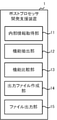
- FIG. 3 is a block diagram of the post processor development support device 1.
- the post-processor development support device 1 has an internal information acquisition unit 11 that acquires the internal information of the numerical control device 3, a function extraction unit 12 that extracts the function of the numerical control device 3 based on the acquired internal information, and an extracted function. It has a function comparison unit 13 for comparison, an output file creation unit 14 for creating a setting file summarizing the functions of the numerical control device 3, and a file output unit 15 for outputting the created setting list to a PC.
- the internal information acquisition unit 11 acquires information stored inside the numerical control device 3 (hereinafter referred to as internal information).
- the internal information includes information about the numerical control device 3 itself and information set according to the machine tool 4 to be controlled.
- the internal information includes system information of the numerical control device 3, parameter information of the machine tool 4, option information of the numerical control device 3, ladder program of the numerical control device 3, and the like.
- the system information of the numerical control device 3 is information about the numerical control device 3 itself.
- the system information includes information on the specifications and specifications of the numerical control device 3 itself.
- the system information includes version information of the numerical control device 3, basic hardware configurations such as a CPU and memory of the numerical control device 3, and the like.
- the parameter information of the machine tool 4 is the machine configuration and shaft configuration of the machine tool 4, the feed speed of the tool, the spindle rotation speed, and the like, and is stored in the memory area of the numerical control device 3.
- the parameter information of the machine tool 4 is set by the engineer according to the machine tool 4 to be controlled. Therefore, the parameter information of the machine tool 4 differs depending on the machine tool 4 connected to the numerical control device 3.
- Option information is information about options added to the numerical control device 3.
- the numerical control device 3 has a basic function and a function to be added as an option.
- the optional functions are selected by the user of the numerical control device 3 and added to the basic functions. Which option is added depends on the numerical control device 3.
- the ladder program is a program for controlling a Programmable Logical Controller (PLC) in the numerical control device 3.
- PLC Programmable Logical Controller
- Instructions called M codes are described in the machining program created by the post processor 23.
- the M code is an auxiliary function of the numerical control device 3 used in the machining program.
- the M code is output from the numerical control device 3 to the PLC, and the machine tool's jig, solenoid valve ON-OFF, limit switch status check, spindle rotation, coolant discharge, and other machine tool phenomena and Control the operation. Since the ladder program corresponding to the M code is created by the engineer of the numerical control device 3, how the machine operates with respect to a certain M code number differs depending on the numerical control device 3. Some M codes are routinely used, such as M03 (rotating the spindle in the forward direction), but the M code programmed by the engineer with the ladder differs for each numerical control device 3.
- the function extraction unit 12 extracts functions that can be used by the numerical control device 3 based on the acquired internal information.
- the function extraction unit 12 extracts environmental information such as what kind of numerical control device 3 controls what kind of machine tool 4 from the parameter information of the machine tool 4 and the version of the numerical control device 3.
- the function extraction unit 12 extracts basic functions from the environmental information of the numerical control device 3 and the machine tool 4, and further extracts the functions added as options.
- the function extraction unit 12 extracts the function added by the option from the option information, if the extracted two or more options have an exclusive function, the function extraction unit 12 enables only one of the functions of those options. , Disable the remaining optional features.
- the function extraction unit 12 does not determine which option is enabled, and the user may be allowed to select it.
- the function extraction unit 12 creates a list of available functions based on the option information. Functions can be extracted using functions and tables.
- the function comparison unit 13 selects an appropriate function from those similar functions. Appropriate functions depend on the set conditions. For example, if the performance improvement effect is a function selection condition, the one with the highest performance improvement effect is selected from among a plurality of similar functions. In addition, a function with a short processing time or a function with low power consumption may be required.
- the setting conditions may be selectable by the user or may be fixed in advance.
- the output file creation unit 14 converts the list of functions extracted by the function extraction unit 12 or the list of functions selected by the function comparison unit 13 into a file in a format that can be read by the post processor 23.
- This file is called a setting file of the post processor 23.
- the setting file format is not particularly limited as long as it can be read by the post processor 23. Any general-purpose format such as XML (Extensive Markup Language), CSV (Comma Separated Value), TXT (text), JSON (Javascript Object Notification) can be read by most information processing devices.
- XML Extensive Markup Language
- CSV Common Separated Value
- TXT text
- JSON Javascript Object Notification
- the file output unit 15 outputs the setting file created by the output file creation unit 14 to the PC 2.
- a wired / wireless network may be used for output of the setting file, or a non-volatile memory such as a USB memory may be used.
- a non-volatile memory such as a USB memory
- FIG. 4 is a block diagram of a PC 2 having a built-in CAM 21.
- PC2 comprises CAD and CAM21, or at least CAM21 only.
- CAD is a system for designing using a computer. CAD creates and edits the appearance and internal structure of the processed product, the arrangement of parts and members, and three-dimensionally displays the shape change of the processed product due to the path of the tool and cutting.
- the CAM 21 includes a main processor 22 that calculates tool path data (CL data) on the model coordinate system created by CAD, and a post processor 23 that converts CL data into a machining program.
- a main processor 22 that calculates tool path data (CL data) on the model coordinate system created by CAD
- a post processor 23 that converts CL data into a machining program.
- the post processor 23 includes a setting information acquisition unit 24 that acquires a setting file from the post processor development support device 1, and a setting information storage unit 25 that stores the contents of the setting file.
- the configuration file contains a list of available features.
- the post processor 23 creates a machining program from CL data based on these setting files.
- the numerical control device 3 outputs internal information to the post processor development support device 1 (step S1).
- the post-processor development support device 1 acquires internal information (step S2), it can grasp the environment of the numerical control device 3 and the machine tool 4 and extract usable basic functions, and can be used by referring to the option information.
- Optional functions are extracted (step S3).
- the post-processor development support device 1 compares the similar functions and selects an appropriate function from the similar functions (step S4).
- an appropriate function is selected in step S4, the post-processor development support device 1 creates a list of available functions (step S5).
- the post-processor development support device 1 converts the created list into a general-purpose format or the like, and creates a setting file that can be read by the PC 2 (step S6).
- the post-processor development support device 1 outputs a setting file to the PC 2 provided with the post-processor 23 (step S7).
- the PC 2 acquires the setting file (step S8), the PC 2 creates a machining program using the function described in the setting file (step S9).
- the post-processor development support system 100 of the first disclosure acquires the internal information of the numerical control device 3, and extracts the functions that can be used by the numerical control device 3 based on the acquired internal information.
- the functions that can be used by the numerical control device 3 can be set without omission.
- the functions that can be used by the numerical control device 3 differ depending on the model of the numerical control device 3. Further, considering which option is added to the numerical control device 3, what function is included in the added option, and which function has an exclusive relationship with which function, the numerical control device is used. It is very complicated to specify the functions that can be used by 3.
- the post-processor development support system 100 of the present disclosure by automatically extracting the functions that can be used by the numerical control device 3, the burden on the developer of the post-processor is reduced, human error is reduced, and the numerical control device is used. New features added by version 3 and options can be set without omission.
- the function comparison unit 13 includes a list table of similar functions. As shown in FIG. 6, the list table of similar functions is classified according to similar functions such as "similar functions related to smoothing" and “similar functions related to rigid taps". "Similar functions related to smoothing” include “smoothing function A”, “smoothing function B", and “smoothing function C”. Each function has a “performance improvement effect”. “Smoothing function A” has a “performance improvement effect” of "high”, “smoothing function B” has a “performance improvement effect” of "medium”, and “smoothing function C” has a “performance improvement effect” of "low”. ".
- the G code of the "smoothing function A" is "G200 Q3"
- the G code of the “smoothing function B” is “G200 Q2”
- the G code of the “smoothing function C” is "G200 Q1”.
- FIG. 6 shows a list of available functions extracted by the function extraction unit 12.
- the function comparison unit 13 compares the list of available functions with the list table of similar functions. When a similar function is included in the available functions, the function comparison unit 13 refers to the "performance improvement effect" in the list table of the similar functions, and selects the function having the highest “performance improvement effect” among the similar functions. select.
- “smoothing function A” and “smoothing function B”, which are “similar functions related to smoothing” are included in the list of available functions. Referring to the list table of similar functions, “smoothing function A” has a “performance improvement effect” of "high”, and “smoothing function B” has a “performance improvement effect” of "medium”.
- the function comparison unit 13 selects "smoothing function A” whose "performance improvement effect” is "high” as an appropriate function.
- the post-processor development support device 1 of the third disclosure has a function of outputting information such as a machine configuration, axis information, and M code to the CAM 21.
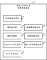
- FIG. 7 is a block diagram of the post-processor development support device 1 of the third disclosure.
- the post-processor development support device 1 shown in FIG. 7 has a machine configuration extraction unit 16 that extracts a machine configuration from the parameter information of the machine tool 4, an axis information extraction unit 17 that extracts axis information from the parameter information of the machine 4, and a ladder program.
- the M code information extraction unit 18 for extracting information about the M code from the above is provided. Since the internal information acquisition unit 11, the function extraction unit 12, the function comparison unit 13, and the file output unit 15 in FIG. 7 are the same as those in the first disclosure, the description thereof will be omitted.
- the machine configuration extraction unit 16 extracts the machine configuration from the parameter information of the machine tool 4, which is the internal information of the numerical control device 3.
- the machine configuration can be extracted from the parameters of the machine tool 4.
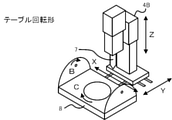
- 8A-8C are examples of mechanical configurations.
- the machine tools shown in FIGS. 8A to 8C are 5-axis machine tools 4 composed of X, Y, Z axes and B, C axes, but each has a different machine configuration.
- FIG. 8A is a tool rotation type machine tool 4A. In the tool rotation type machine tool 4A, the tool 7 moves on the XYZ axes and rotates on the rotation axes of the C axis and the B axis.
- FIG. 8B is a table rotary machine tool 4B.
- FIG. 8C is a mixed machine tool 4C.
- the tool 7 moves on the XYZ axis and rotates on the rotation axis of the B axis, and the table 8 on which the workpiece is placed rotates on the rotation axis of the C axis.
- the 5-axis machine tool 4 includes not only the above three types but also a machine configuration with other rotating axes such as X, Y, Z axis and A, C axis, or X, Y, Z axis and A, B axis. exist.
- the post processor 23 does not know the machine configuration of the machine tool 4 to be controlled. In order to create a machining program, it is necessary to set the machine configuration of the machine tool 4 to be controlled in the post processor 23.
- the machine configuration extraction unit 16 automatically extracts the machine configuration from the parameters.
- the axis information extraction unit 17 extracts axis information from parameter information or the like, which is internal information of the numerical control device 3.
- the axis information required to create a machining program includes the axis name, minimum command unit, operating range, maximum cutting feed rate, rollover, and absolute command rotation direction.
- the axis name is a name for designating the axis to be moved in the machining program.
- the minimum command unit indicates the unit of how many digits after the decimal point can be commanded when indicating the coordinates of the movement destination of the axis.
- the operating range is the moving range of the tool that can be specified as a moving command.
- the maximum cutting feed rate is the maximum cutting speed, and the machining program sets the speed below that speed.
- the rollover is a setting of whether the coordinate value of the angle returns to 0 or the coordinate value of the angle as it is increases on the rotation axis when the axis makes one rotation.
- the rotation direction of the absolute command is the amount of movement, whether the rotation direction of the rotation axis moves clockwise or counterclockwise according to the +/- sign when the angle of the rotation axis is commanded by the absolute coordinate command. It is a setting of whether to rotate by calculating the direction with less (near). If there is a risk of interference between the machine tool and the tool, it is necessary to confirm that the setting allows the direction of rotation to be specified.
- the M code information extraction unit 18 extracts the M code created by the engineer of the numerical control device 3 from the ladder program.
- the M code is an instruction to output a signal from the numerical control device 3 to the PLC.
- Some M codes are routinely used, such as M03, but some are created by engineers of numerical control devices.
- the operation of the M code created by the engineer of the numerical control device differs depending on each numerical control device.
- the relationship between the M code and the operation of the machine can be determined from the M code number of the ladder program and its comment, or the name of the signal that changes depending on the M code.
- the M code extracted by the M code information extraction unit 18 can be used in the machining program.
- the output file creation unit 14 uses the machine configuration extracted by the machine configuration extraction unit 16, the axis information extracted by the axis information extraction unit 17, the information about the M code extracted by the M code information extraction unit 18, and the numerical control device 3. Create a configuration file that contains a list of possible features.
- the setting file is a file in a format that can be read by a PC on the CAM side.
- the file format is, for example, a general-purpose format such as XML, CSV, TXT, JSON.
- the file output unit 15 outputs the setting file created by the output file creation unit 14 to the PC 2.
- a wired / wireless network may be used for output of the setting file, or a non-volatile memory such as a USB memory may be used.
- a non-volatile memory such as a USB memory
- the post-processor development support device 1 of the third disclosure outputs the machine configuration, axis information, and M code information of the machine tool 4 to the PC 2 provided with the CAM 21. Since the machine configuration, axis information, and M code information of the machine tool 4 are necessary information for creating a machining program, they must be set accurately. This information is enormous, and finding out which information to get from where is a heavy burden for developers.
- the post-processor development support device 1 of the third disclosure automatically extracts the machine configuration, axis configuration, and M code of the machine tool 4 necessary for the development of the post-processor 23, and outputs the machine tool 21 in a readable format. , Reduce the burden on developers, reduce human error, and improve development efficiency.
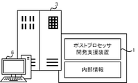
- the post-processor development support device 1 may be mounted on a general information processing device such as a PC 5, a numerical control device 3, or a PC 2 equipped with a CAM 21.
- the post-processor development support device 1 of FIGS. 9A to 9C is implemented by the CPU 111 executing a predetermined program.
- the post-processor development support device 1 is mounted on a general information processing device such as a PC 5.
- the post-processor development support device 1 is mounted on the numerical control device 3 or the IPC6 (industrial PC).
- the post-processor development support device 1 By mounting the post-processor development support device 1 on the numerical control device 3 or the IPC 6, it is possible to output the files necessary for the development of the post-processor 23 without outputting the internal information described later to the outside.
- a non-volatile memory such as a USB memory may be used for file transfer, or the Internet may be set. This eliminates the need for settings for communicating internal information and facilitates the output of files to a PC.
- the post processor development support device 1 is mounted on the PC 2 provided with the CAM 21. When the post-processor development support device 1 is mounted on the PC 2 provided with the CAM 21, it is possible to directly take in the information of the numerical control device 3 and automatically complete the setting of the post-processor 23. Therefore, even if the numerical control device 3 does not have the development support function of the post processor 23, the post processor 23 can be set on the PC2 side.
- Post-processor development support system 1 Post-processor development support device 2 PC equipped with CAM 3 Numerical control device 4 Machine tool 5 Post processor development support unit 11 Internal information acquisition unit 12 Function extraction unit 13 Function comparison unit 14 Output file creation unit 15 File output unit 16 Machine configuration extraction unit 17 Axis information extraction unit 21 CAM 22 Main processor 23 Post processor
Landscapes
- Engineering & Computer Science (AREA)
- Human Computer Interaction (AREA)
- Manufacturing & Machinery (AREA)
- Physics & Mathematics (AREA)
- General Physics & Mathematics (AREA)
- Automation & Control Theory (AREA)
- Numerical Control (AREA)
Priority Applications (4)
| Application Number | Priority Date | Filing Date | Title |
|---|---|---|---|
| CN202180056904.4A CN116057486B (zh) | 2020-08-06 | 2021-08-03 | 后处理器开发辅助装置、后处理器开发辅助系统及计算机能够执行的方法 |
| JP2022541563A JP7518171B2 (ja) | 2020-08-06 | 2021-08-03 | ポストプロセッサ開発支援装置、ポストプロセッサ開発支援システム、及びコンピュータが実行可能な方法 |
| DE112021004148.7T DE112021004148T5 (de) | 2020-08-06 | 2021-08-03 | Postprozessorentwicklungs-unterstützungsvorrichtung, postprozessorentwicklungs-unterstützungssystem und computerausführbares verfahren |
| US18/005,967 US20230315051A1 (en) | 2020-08-06 | 2021-08-03 | Post-processor development support device, post-processor development support system, and computer-executable method |
Applications Claiming Priority (2)
| Application Number | Priority Date | Filing Date | Title |
|---|---|---|---|
| JP2020-134027 | 2020-08-06 | ||
| JP2020134027 | 2020-08-06 |
Publications (1)
| Publication Number | Publication Date |
|---|---|
| WO2022030485A1 true WO2022030485A1 (ja) | 2022-02-10 |
Family
ID=80118119
Family Applications (1)
| Application Number | Title | Priority Date | Filing Date |
|---|---|---|---|
| PCT/JP2021/028757 Ceased WO2022030485A1 (ja) | 2020-08-06 | 2021-08-03 | ポストプロセッサ開発支援装置、ポストプロセッサ開発支援システム、及びコンピュータが実行可能な方法 |
Country Status (5)
| Country | Link |
|---|---|
| US (1) | US20230315051A1 (https=) |
| JP (1) | JP7518171B2 (https=) |
| CN (1) | CN116057486B (https=) |
| DE (1) | DE112021004148T5 (https=) |
| WO (1) | WO2022030485A1 (https=) |
Cited By (2)
| Publication number | Priority date | Publication date | Assignee | Title |
|---|---|---|---|---|
| WO2025022526A1 (ja) * | 2023-07-24 | 2025-01-30 | 株式会社Fuji | 加工提案表作成装置、及び加工提案表作成プログラム |
| WO2026013708A1 (ja) * | 2024-07-08 | 2026-01-15 | ファナック株式会社 | 機能状態判定装置、及びコンピュータが読み取り可能な記憶媒体 |
Families Citing this family (1)
| Publication number | Priority date | Publication date | Assignee | Title |
|---|---|---|---|---|
| CN118946864A (zh) * | 2022-03-22 | 2024-11-12 | 西门子工业软件有限公司 | 管理后处理器、特别是确定新的后处理器,以使用机床方法、计算机系统和机床来加工 |
Citations (2)
| Publication number | Priority date | Publication date | Assignee | Title |
|---|---|---|---|---|
| JPH0546228A (ja) * | 1991-08-19 | 1993-02-26 | Okuma Mach Works Ltd | 自動プログラミング装置におけるポストプロセツサデータの設定・変更方法 |
| JP2008059518A (ja) * | 2006-09-04 | 2008-03-13 | Mitsubishi Heavy Ind Ltd | ポストプロセッサ開発支援システム及びそれを用いたcamシステム |
Family Cites Families (25)
| Publication number | Priority date | Publication date | Assignee | Title |
|---|---|---|---|---|
| KR20050008207A (ko) * | 2003-07-14 | 2005-01-21 | 두산중공업 주식회사 | 발전소에서 포스트 프로세서 운용 방법 |
| DE10352815B4 (de) * | 2003-11-12 | 2009-06-25 | Siemens Ag | Simulationsverfahren für eine Bearbeitung eines Werkstücks durch eine Werkzeugmaschine und korrespondierender Rechner |
| JP4392533B2 (ja) * | 2003-12-11 | 2010-01-06 | 株式会社日立製作所 | 数値制御曲面加工装置 |
| US20060036394A1 (en) * | 2004-08-12 | 2006-02-16 | Wen-Ling Chen | Universal and integrated wafer testing real-time monitoring software system and its open system architecture |
| US7747421B2 (en) * | 2005-12-23 | 2010-06-29 | The Boeing Company | Head assignment modeling and simulation |
| US8577655B2 (en) * | 2008-06-26 | 2013-11-05 | Siemens Product Lifecycle Management Software Inc. | System and method for constructing virtual NC controllers for machine tool simulation |
| US9436176B2 (en) * | 2010-04-21 | 2016-09-06 | Mitsubishi Electric Corporation | Numerical control method and device thereof |
| JP5982252B2 (ja) * | 2012-10-23 | 2016-08-31 | 東芝機械株式会社 | プログラム生成システム |
| ES2629831T3 (es) * | 2013-01-17 | 2017-08-16 | Agie Charmilles Sa | Máquina fresadora de descarga eléctrica |
| US9846424B2 (en) * | 2013-03-29 | 2017-12-19 | Mitsubishi Electric Corporation | Numerical control apparatus |
| JP5452788B1 (ja) * | 2013-06-06 | 2014-03-26 | 三菱電機株式会社 | 数値制御装置 |
| US20150127139A1 (en) * | 2013-11-07 | 2015-05-07 | The Boeing Company | Real-Time Numerical Control Tool Path Adaptation Using Force Feedback |
| US9513623B2 (en) * | 2014-01-21 | 2016-12-06 | Mitsubishi Electric Research Laboratories, Inc. | Method for generating trajectory for numerical control process |
| US9798315B2 (en) * | 2014-10-14 | 2017-10-24 | Siemens Product Lifecycle Management Software Inc. | Machine tool post configurator systems and methods |
| WO2016065491A1 (en) * | 2014-10-31 | 2016-05-06 | Cloudbased Industry 4.0 Technologies Ag | Method for optimizing the productivity of a machining process of a cnc machine |
| CN107111297B (zh) * | 2014-10-31 | 2021-03-26 | 制造业大数据有限公司 | 用于由至少一台计算机数控机器加工的工件的部件分析的计算机实现方法 |
| CA3035607A1 (en) * | 2016-09-08 | 2018-03-15 | Fives Line Machines Inc. | Machining station, workpiece holding system, and method of machining a workpiece |
| JP6490125B2 (ja) * | 2017-03-10 | 2019-03-27 | ファナック株式会社 | 数値制御装置及びcad/cam−cnc統合システム |
| JP6646027B2 (ja) * | 2017-10-30 | 2020-02-14 | ファナック株式会社 | ポストプロセッサ装置、加工プログラム生成方法、cnc加工システム及び加工プログラム生成用プログラム |
| US20190351484A1 (en) * | 2018-05-20 | 2019-11-21 | 3D Flexible, Inc. | Metal pastes for additive manufacturing |
| JP2019219878A (ja) * | 2018-06-19 | 2019-12-26 | ファナック株式会社 | 数値制御装置及び誤入力検出方法 |
| EP3671381A1 (en) * | 2018-12-20 | 2020-06-24 | Etxe-Tar, S.A. | Methods and systems for operating a machine in a manufacturing process |
| JP6868161B1 (ja) * | 2019-06-28 | 2021-05-12 | Dmg森精機株式会社 | 情報処理装置、情報処理方法および情報処理プログラム |
| CN114365048B (zh) * | 2019-09-12 | 2022-12-02 | 三菱电机株式会社 | 数控装置 |
| EP3945381A1 (de) * | 2020-07-31 | 2022-02-02 | Siemens Aktiengesellschaft | Herstellung durch kegelsegmente bestimmbarer flächen mittels einer werkzeugmaschine |
-
2021
- 2021-08-03 US US18/005,967 patent/US20230315051A1/en active Pending
- 2021-08-03 WO PCT/JP2021/028757 patent/WO2022030485A1/ja not_active Ceased
- 2021-08-03 JP JP2022541563A patent/JP7518171B2/ja active Active
- 2021-08-03 DE DE112021004148.7T patent/DE112021004148T5/de active Pending
- 2021-08-03 CN CN202180056904.4A patent/CN116057486B/zh active Active
Patent Citations (2)
| Publication number | Priority date | Publication date | Assignee | Title |
|---|---|---|---|---|
| JPH0546228A (ja) * | 1991-08-19 | 1993-02-26 | Okuma Mach Works Ltd | 自動プログラミング装置におけるポストプロセツサデータの設定・変更方法 |
| JP2008059518A (ja) * | 2006-09-04 | 2008-03-13 | Mitsubishi Heavy Ind Ltd | ポストプロセッサ開発支援システム及びそれを用いたcamシステム |
Cited By (2)
| Publication number | Priority date | Publication date | Assignee | Title |
|---|---|---|---|---|
| WO2025022526A1 (ja) * | 2023-07-24 | 2025-01-30 | 株式会社Fuji | 加工提案表作成装置、及び加工提案表作成プログラム |
| WO2026013708A1 (ja) * | 2024-07-08 | 2026-01-15 | ファナック株式会社 | 機能状態判定装置、及びコンピュータが読み取り可能な記憶媒体 |
Also Published As
| Publication number | Publication date |
|---|---|
| US20230315051A1 (en) | 2023-10-05 |
| JP7518171B2 (ja) | 2024-07-17 |
| CN116057486A (zh) | 2023-05-02 |
| DE112021004148T5 (de) | 2023-06-22 |
| CN116057486B (zh) | 2025-07-18 |
| JPWO2022030485A1 (https=) | 2022-02-10 |
Similar Documents
| Publication | Publication Date | Title |
|---|---|---|
| JP5414948B1 (ja) | 数値制御装置 | |
| EP2862030B1 (en) | Computer aided manufacturing (cam) integrated computer numerically controlled (cnc) control of machines | |
| EP3964904B1 (en) | Information processing device, information processing method, and information processing program | |
| WO2022030485A1 (ja) | ポストプロセッサ開発支援装置、ポストプロセッサ開発支援システム、及びコンピュータが実行可能な方法 | |
| JP7177905B1 (ja) | 情報処理装置 | |
| JP6770018B2 (ja) | 設定装置及び設定プログラム | |
| EP1443435A2 (en) | Horizontally structured CAD/CAM coordinate system for manufacturing design | |
| CN114365048A (zh) | 数控装置 | |
| JPH09212227A (ja) | 数値制御装置によって制御され運転される機械における運転情報設定方法 | |
| JP6987960B1 (ja) | 情報処理装置 | |
| WO2022138055A1 (ja) | 情報処理装置および情報処理プログラム | |
| JP5123502B2 (ja) | ポストプロセッサ開発支援システム及びそれを用いたcamシステム | |
| WO1990014620A1 (fr) | Systeme d'affichage de donnees sur un ecran | |
| Martinova et al. | Development of a cross-platform software application for programming CNC machine tools | |
| JP5763352B2 (ja) | Ncプログラム作成装置 | |
| Xu et al. | Development of a G-code free, STEP-compliant CNC lathe | |
| Epureanu et al. | Reconfigurable machine tool programming–a new approach | |
| JP2024073818A (ja) | 制御システムおよび情報処理方法 | |
| CN117099061A (zh) | 信息处理装置及信息处理程序 | |
| KR100398004B1 (ko) | 수치제어 공작기계의 지-코드 생성방법 | |
| WO1991014977A1 (fr) | Systeme de definition de symboles de pmc | |
| JP2002132316A (ja) | 数値制御装置およびそのソフトウエア組み込みシステム | |
| Elias et al. | A Framework for a Development of an Intelligent CNC Controller Based on Step-NC | |
| Kain et al. | A method and software prototype to support on-line planning on CNC machines | |
| Tunggal | A REVIEW OF INTELLIGENT CNC CONTROLLER DEVELOPMENT BASED ON STEP-NC |
Legal Events
| Date | Code | Title | Description |
|---|---|---|---|
| 121 | Ep: the epo has been informed by wipo that ep was designated in this application |
Ref document number: 21854619 Country of ref document: EP Kind code of ref document: A1 |
|
| ENP | Entry into the national phase |
Ref document number: 2022541563 Country of ref document: JP Kind code of ref document: A |
|
| 122 | Ep: pct application non-entry in european phase |
Ref document number: 21854619 Country of ref document: EP Kind code of ref document: A1 |
|
| WWG | Wipo information: grant in national office |
Ref document number: 202180056904.4 Country of ref document: CN |