WO2022030457A1 - 投与デバイス - Google Patents
投与デバイス Download PDFInfo
- Publication number
- WO2022030457A1 WO2022030457A1 PCT/JP2021/028652 JP2021028652W WO2022030457A1 WO 2022030457 A1 WO2022030457 A1 WO 2022030457A1 JP 2021028652 W JP2021028652 W JP 2021028652W WO 2022030457 A1 WO2022030457 A1 WO 2022030457A1
- Authority
- WO
- WIPO (PCT)
- Prior art keywords
- needle
- cartridge
- case
- administration
- pressing force
- Prior art date
Links
Images


Classifications
-
- A—HUMAN NECESSITIES
- A61—MEDICAL OR VETERINARY SCIENCE; HYGIENE
- A61M—DEVICES FOR INTRODUCING MEDIA INTO, OR ONTO, THE BODY; DEVICES FOR TRANSDUCING BODY MEDIA OR FOR TAKING MEDIA FROM THE BODY; DEVICES FOR PRODUCING OR ENDING SLEEP OR STUPOR
- A61M5/00—Devices for bringing media into the body in a subcutaneous, intra-vascular or intramuscular way; Accessories therefor, e.g. filling or cleaning devices, arm-rests
- A61M5/46—Devices for bringing media into the body in a subcutaneous, intra-vascular or intramuscular way; Accessories therefor, e.g. filling or cleaning devices, arm-rests having means for controlling depth of insertion
-
- A—HUMAN NECESSITIES
- A61—MEDICAL OR VETERINARY SCIENCE; HYGIENE
- A61M—DEVICES FOR INTRODUCING MEDIA INTO, OR ONTO, THE BODY; DEVICES FOR TRANSDUCING BODY MEDIA OR FOR TAKING MEDIA FROM THE BODY; DEVICES FOR PRODUCING OR ENDING SLEEP OR STUPOR
- A61M5/00—Devices for bringing media into the body in a subcutaneous, intra-vascular or intramuscular way; Accessories therefor, e.g. filling or cleaning devices, arm-rests
- A61M5/178—Syringes
- A61M5/31—Details
- A61M5/315—Pistons; Piston-rods; Guiding, blocking or restricting the movement of the rod or piston; Appliances on the rod for facilitating dosing ; Dosing mechanisms
- A61M5/31565—Administration mechanisms, i.e. constructional features, modes of administering a dose
- A61M5/31566—Means improving security or handling thereof
- A61M5/3157—Means providing feedback signals when administration is completed
-
- A—HUMAN NECESSITIES
- A61—MEDICAL OR VETERINARY SCIENCE; HYGIENE
- A61M—DEVICES FOR INTRODUCING MEDIA INTO, OR ONTO, THE BODY; DEVICES FOR TRANSDUCING BODY MEDIA OR FOR TAKING MEDIA FROM THE BODY; DEVICES FOR PRODUCING OR ENDING SLEEP OR STUPOR
- A61M5/00—Devices for bringing media into the body in a subcutaneous, intra-vascular or intramuscular way; Accessories therefor, e.g. filling or cleaning devices, arm-rests
- A61M5/178—Syringes
- A61M5/24—Ampoule syringes, i.e. syringes with needle for use in combination with replaceable ampoules or carpules, e.g. automatic
- A61M5/2422—Ampoule syringes, i.e. syringes with needle for use in combination with replaceable ampoules or carpules, e.g. automatic using emptying means to expel or eject media, e.g. pistons, deformation of the ampoule, or telescoping of the ampoule
-
- A—HUMAN NECESSITIES
- A61—MEDICAL OR VETERINARY SCIENCE; HYGIENE
- A61M—DEVICES FOR INTRODUCING MEDIA INTO, OR ONTO, THE BODY; DEVICES FOR TRANSDUCING BODY MEDIA OR FOR TAKING MEDIA FROM THE BODY; DEVICES FOR PRODUCING OR ENDING SLEEP OR STUPOR
- A61M5/00—Devices for bringing media into the body in a subcutaneous, intra-vascular or intramuscular way; Accessories therefor, e.g. filling or cleaning devices, arm-rests
- A61M5/178—Syringes
- A61M5/31—Details
- A61M5/315—Pistons; Piston-rods; Guiding, blocking or restricting the movement of the rod or piston; Appliances on the rod for facilitating dosing ; Dosing mechanisms
- A61M5/31501—Means for blocking or restricting the movement of the rod or piston
-
- A—HUMAN NECESSITIES
- A61—MEDICAL OR VETERINARY SCIENCE; HYGIENE
- A61M—DEVICES FOR INTRODUCING MEDIA INTO, OR ONTO, THE BODY; DEVICES FOR TRANSDUCING BODY MEDIA OR FOR TAKING MEDIA FROM THE BODY; DEVICES FOR PRODUCING OR ENDING SLEEP OR STUPOR
- A61M5/00—Devices for bringing media into the body in a subcutaneous, intra-vascular or intramuscular way; Accessories therefor, e.g. filling or cleaning devices, arm-rests
- A61M5/42—Devices for bringing media into the body in a subcutaneous, intra-vascular or intramuscular way; Accessories therefor, e.g. filling or cleaning devices, arm-rests having means for desensitising skin, for protruding skin to facilitate piercing, or for locating point where body is to be pierced
- A61M5/425—Protruding skin to facilitate piercing, e.g. vacuum cylinders, vein immobilising means
-
- A—HUMAN NECESSITIES
- A61—MEDICAL OR VETERINARY SCIENCE; HYGIENE
- A61M—DEVICES FOR INTRODUCING MEDIA INTO, OR ONTO, THE BODY; DEVICES FOR TRANSDUCING BODY MEDIA OR FOR TAKING MEDIA FROM THE BODY; DEVICES FOR PRODUCING OR ENDING SLEEP OR STUPOR
- A61M5/00—Devices for bringing media into the body in a subcutaneous, intra-vascular or intramuscular way; Accessories therefor, e.g. filling or cleaning devices, arm-rests
- A61M5/178—Syringes
- A61M5/20—Automatic syringes, e.g. with automatically actuated piston rod, with automatic needle injection, filling automatically
- A61M2005/2006—Having specific accessories
- A61M2005/2013—Having specific accessories triggering of discharging means by contact of injector with patient body
-
- A—HUMAN NECESSITIES
- A61—MEDICAL OR VETERINARY SCIENCE; HYGIENE
- A61M—DEVICES FOR INTRODUCING MEDIA INTO, OR ONTO, THE BODY; DEVICES FOR TRANSDUCING BODY MEDIA OR FOR TAKING MEDIA FROM THE BODY; DEVICES FOR PRODUCING OR ENDING SLEEP OR STUPOR
- A61M5/00—Devices for bringing media into the body in a subcutaneous, intra-vascular or intramuscular way; Accessories therefor, e.g. filling or cleaning devices, arm-rests
- A61M5/178—Syringes
- A61M5/24—Ampoule syringes, i.e. syringes with needle for use in combination with replaceable ampoules or carpules, e.g. automatic
- A61M5/2455—Ampoule syringes, i.e. syringes with needle for use in combination with replaceable ampoules or carpules, e.g. automatic with sealing means to be broken or opened
- A61M5/2466—Ampoule syringes, i.e. syringes with needle for use in combination with replaceable ampoules or carpules, e.g. automatic with sealing means to be broken or opened by piercing without internal pressure increase
- A61M2005/247—Ampoule syringes, i.e. syringes with needle for use in combination with replaceable ampoules or carpules, e.g. automatic with sealing means to be broken or opened by piercing without internal pressure increase with fixed or steady piercing means, e.g. piercing under movement of ampoule
-
- A—HUMAN NECESSITIES
- A61—MEDICAL OR VETERINARY SCIENCE; HYGIENE
- A61M—DEVICES FOR INTRODUCING MEDIA INTO, OR ONTO, THE BODY; DEVICES FOR TRANSDUCING BODY MEDIA OR FOR TAKING MEDIA FROM THE BODY; DEVICES FOR PRODUCING OR ENDING SLEEP OR STUPOR
- A61M5/00—Devices for bringing media into the body in a subcutaneous, intra-vascular or intramuscular way; Accessories therefor, e.g. filling or cleaning devices, arm-rests
- A61M5/178—Syringes
- A61M5/31—Details
- A61M5/32—Needles; Details of needles pertaining to their connection with syringe or hub; Accessories for bringing the needle into, or holding the needle on, the body; Devices for protection of needles
- A61M5/3205—Apparatus for removing or disposing of used needles or syringes, e.g. containers; Means for protection against accidental injuries from used needles
- A61M5/321—Means for protection against accidental injuries by used needles
- A61M5/3243—Means for protection against accidental injuries by used needles being axially-extensible, e.g. protective sleeves coaxially slidable on the syringe barrel
- A61M5/326—Fully automatic sleeve extension, i.e. in which triggering of the sleeve does not require a deliberate action by the user
- A61M2005/3267—Biased sleeves where the needle is uncovered by insertion of the needle into a patient's body
-
- A—HUMAN NECESSITIES
- A61—MEDICAL OR VETERINARY SCIENCE; HYGIENE
- A61M—DEVICES FOR INTRODUCING MEDIA INTO, OR ONTO, THE BODY; DEVICES FOR TRANSDUCING BODY MEDIA OR FOR TAKING MEDIA FROM THE BODY; DEVICES FOR PRODUCING OR ENDING SLEEP OR STUPOR
- A61M2205/00—General characteristics of the apparatus
- A61M2205/58—Means for facilitating use, e.g. by people with impaired vision
- A61M2205/581—Means for facilitating use, e.g. by people with impaired vision by audible feedback
-
- A—HUMAN NECESSITIES
- A61—MEDICAL OR VETERINARY SCIENCE; HYGIENE
- A61M—DEVICES FOR INTRODUCING MEDIA INTO, OR ONTO, THE BODY; DEVICES FOR TRANSDUCING BODY MEDIA OR FOR TAKING MEDIA FROM THE BODY; DEVICES FOR PRODUCING OR ENDING SLEEP OR STUPOR
- A61M2205/00—General characteristics of the apparatus
- A61M2205/58—Means for facilitating use, e.g. by people with impaired vision
- A61M2205/582—Means for facilitating use, e.g. by people with impaired vision by tactile feedback
-
- A—HUMAN NECESSITIES
- A61—MEDICAL OR VETERINARY SCIENCE; HYGIENE
- A61M—DEVICES FOR INTRODUCING MEDIA INTO, OR ONTO, THE BODY; DEVICES FOR TRANSDUCING BODY MEDIA OR FOR TAKING MEDIA FROM THE BODY; DEVICES FOR PRODUCING OR ENDING SLEEP OR STUPOR
- A61M2205/00—General characteristics of the apparatus
- A61M2205/58—Means for facilitating use, e.g. by people with impaired vision
- A61M2205/583—Means for facilitating use, e.g. by people with impaired vision by visual feedback
Definitions
- the present invention relates to a drug solution administration device.
- an intradermal administration device has been developed for the purpose of reducing the dose of a drug solution.
- the development is not easy because there are many design items to be satisfied.
- Design items that should be satisfied include, for example, controlling the puncture depth of the needle that pierces the skin in order to accurately administer the drug solution, preventing needle puncture accidents after use, and preventing repeated use. There is.
- Patent Documents 1 and 2 separately provide a cylindrical or dome-shaped structure on the needle tip side, and when the structure comes into contact with the skin, the device spreads the skin to make the thickness of the skin constant. Is disclosed.
- the thickness of the skin can be stabilized to a constant level, but the puncture depth of the needle increases due to the difference in pressing force by an operator such as a nurse. Not stable. Therefore, it is not easy to make the puncture depth of the needle pierced in the skin constant.
- Such problems are not limited to intradermal administration devices, but may be common to subcutaneous tissue, intramuscular, or other in vivo administration devices.
- the present invention has been made in view of the above problems, and an object of the present invention is to provide an administration device capable of easily making the puncture depth of a needle substantially constant.
- the needle punctured in the living body, the cartridge capable of accommodating the drug solution administered in the living body through the needle, and the first end portion pressed against the skin can be opened or opened.
- the needle and the cartridge are movably stored on the first end side, and when the needle is moved to the first end side, the needle advances to the outside of the first end. It is interposed between the possible case and the cartridge and the case so as to generate a reaction force, and controls the pressing force of the case against the skin when the needle moves toward the first end portion.
- the pressing force control member can continue to generate the reaction force.
- a dosing device A dosing device.
- a needle pierced in the living body, a cartridge capable of accommodating a drug solution to be administered in the living body through the needle, and a first end portion pressed against the skin can be opened or opened.
- the needle and the cartridge are movably stored on the first end side, and the needle can be moved to the outside of the first end by moving the needle to the first end side.
- a pressing force is interposed between the cartridge and the case so as to generate a reaction force, and controls the pressing force of the case against the skin when the needle moves toward the first end portion.
- the first end is provided with a force control member, and the needle is moved toward the first end through the opening of the first end in a state where the first end of the case is pressed against the skin.
- An administration device in which the needle is advanced to the outside of the portion and the needle is pierced into the living body, and the administration device moves the needle toward the first end portion through the opening of the first end portion.
- the reaction force generated by the pressing force control member is continued, and the case is applied to the skin.
- the puncture depth of the needle is configured to be substantially constant in a state where the puncture of the needle into the living body is completed, and the needle is housed in the cartridge.
- the reaction force is continuously generated by the pressing force control member, and the puncture depth of the needle is configured to be substantially constant. It is a dosing device.
- the force applied to the first end portion side of the cartridge is released, so that the cartridge is integrated with the needle and is relative to the case. In addition, it may be moved to the side opposite to the first end portion.
- the pressing force control member integrally attaches the cartridge to the case with respect to the needle. It may be relatively moved to the side opposite to the first end side.
- a notification mechanism may be provided to notify the operator of the completion of administration of the drug solution by generating a sound or force transmitted to the operator by engaging with the drug solution when the administration of the drug solution is completed.
- the needle is supported at a position away from the cartridge in the initial state, and is fixed to the case.
- the fixing is released, the first end portion is integrated with the needle.
- the cartridge may be provided with a fixing release mechanism for releasing the fixing after the cartridge moved to the first end side is integrated with the needle.
- the cartridge is provided with a pushing member that applies a force to the first end side of the cartridge by being pushed by the operator and moving to the first end side, and the cartridge contains the chemical solution. It may have a cartridge main body and a piston that is pushed by the push member and moves toward the first end portion with respect to the cartridge main body to push out the chemical solution through the needle.
- the present invention is the administration device used for intradermal administration.
- an administration device capable of easily making the puncture depth of a needle substantially constant.
- FIG. 1 is a cross-sectional perspective view of the administration device viewed in the direction of arrows XX in FIG. 1, showing an initial state.
- FIG. 1 is a cross-sectional perspective view of the administration device viewed in the direction of arrows XX of FIG. 1, showing an engaged state in which the cartridge is integrated with the needle. It is sectional drawing of the administration device seen in the direction of arrow XX of FIG. 1, and shows the initial state (corresponding to FIG. 4A).
- FIG. 4B It is sectional drawing of the administration device seen in the direction of arrow XX of FIG. 1, and shows the engagement state in which a cartridge is integrated with a needle (FIG. 4B correspondence figure). It is sectional drawing of the administration device seen in the direction of arrow XX of FIG. 1, and shows the state at the start of administration of a drug solution. It is sectional drawing of the administration device seen in the direction of arrow XX of FIG. 1, and shows the state at the time of completion of administration of a drug solution. It is sectional drawing of the administration device seen in the direction of arrow XX of FIG. 1, and shows the state in which the needle is retracted in the lower case after the administration of a drug solution is completed.
- arrow F indicates a forward direction
- arrow B indicates a backward direction
- arrow L indicates a left direction
- arrow R indicates a right direction
- arrow U indicates an upward direction
- arrow D indicates a downward direction.
- each direction will be used, but the posture when using the administration device 1 is not limited to a specific posture. That is, the administration device 1 is described as being used toward the downward direction D, but can also be used, for example, toward the upward direction U.
- the downward direction D corresponds to the direction toward the "first end side" in claim 1.
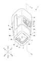
- FIG. 1 is an external perspective view of an administration device according to an embodiment of the present invention.
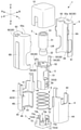
- FIG. 2 is an exploded perspective view of the administration device shown in FIG.
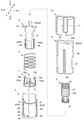
- FIG. 3 is an exploded cross-sectional perspective view of the administration device shown in FIG.
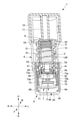
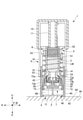
- FIG. 4A is a cross-sectional perspective view of the administration device viewed in the direction of arrows XX of FIG. 1 and shows an initial state.
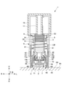
- FIG. 4B is a cross-sectional perspective view of the administration device viewed in the direction of arrows XX of FIG. 1 and shows an engaged state in which the cartridge is integrated with the needle.
- the administration device 1 shown in FIGS. 1 to 4B is an intradermal syringe that administers the drug solution LM between the epidermis and the dermis, that is, the intradermal IN (see FIG. 5D and the like).
- the administration device 1 includes a needle 2, a cartridge 3, a lower case 4 (case), a middle case 5, a spring 6 (pressing force control member), a needle base 7, and a fixing release mechanism 8.
- the upper case 9, the head cover 10, the notification mechanism 20, and the like are provided.
- the needle 2 is arranged so as to extend along the upward direction U and the downward direction D (vertical direction). After the upper U side of the needle 2 punctures the seal 32 of the cartridge 3 to break the seal 32, the downward D side of the needle 2 is punctured into the intradermal IN (see FIG. 5D and the like). As a result, the needle 2 becomes a flow path of the drug solution LM when the drug solution LM contained in the cartridge 3 is administered to the intradermal IN.
- the needle 2 is stored in the lower case 4 at times other than the time of puncture, and is fixed at a position away from the cartridge 3 by being supported by the needle base 7 in the initial state. When the fixing is released, the needle 2 can move downward D integrally with the needle base 7.
- the material of the needle 2 may be a metal material, or may be a resin having lower rigidity and higher flexibility than the metal material.
- the cartridge 3 is a prefilled type that contains the drug solution LM to be administered to the intradermal IN via the needle 2.
- the cartridge 3 contains the chemical solution LM in a hermetically sealed manner to prevent deterioration.
- the cartridge 3 has a cartridge main body 31, a seal 32, and a piston 33. When the needle 2 sticks into the seal 32 at the time of use, the chemical solution LM can be used.
- the cartridge 3 is stored in the middle case 5.
- the cartridge 3 and the middle case 5 are integrated.
- the cartridge 3 is housed in the lower case 4 integrally with the middle case 5 so as to be maintained in a predetermined position by a coiled spring 6 interposed between the lower case 4 and the middle case 5.
- the cartridge 3 moves downward D integrally with the middle case 5 against the reaction force of the spring 6 by applying a downward force to the pushing member 11 of the head cover 10.
- the cartridge 3 moves upward U together with the middle case 5 as the spring 6 expands (that is, due to the reaction force of the spring 6).
- the cartridge main body 31 is a cylinder in which both ends in the upward direction U and the downward direction D are open, and is not particularly limited, but may be made of a transparent material.
- This "transparency" may be transparent or translucent, and specifically may be highly transparent, and may be less transparent than glass (such as transparent polypropylene), such as a plastic material. There may be.
- the cartridge body 31 may be a colored (colored) transparent container (for example, a colored vial bottle) in order to prevent deterioration of the contained chemical solution LM.
- the cartridge body 31 contains the chemical solution LM.
- the end portion of the cartridge body 31 in the downward direction D is closed with the seal 32.
- a piston 33 is fitted at the end of the cartridge body 31 in the upward direction U.
- the seal 32 is broken when the needle 2 is pierced. After the seal 32 is broken, the piston 33 moves downward D with respect to the cartridge main body 31 when a predetermined force or more is applied to the downward D, whereby the chemical solution LM is moved through the needle 2. Push out. That is, the piston 33 can move the cartridge body 31 downward D against the reaction force of the spring 6 even when a force is applied in the downward direction D after the seal 32 is broken. If there is, it does not move downward D relative to the cartridge main body 31, but moves downward D integrally with the cartridge main body 31.
- the lower case 4 is configured in a substantially cylindrical shape as a lower housing in the administration device 1 by connecting a pair of left and right members 4A and 4B to each other.
- the pair of left and right members 4A and 4B are connected to each other to form the lower case 4, but the present invention is not limited to this.
- the lower case 4 may be integrally formed by integral molding or the like.
- the lower end 45 (first end) of the lower case 4 is open.
- the needle 2 and the cartridge 3 and the like are movably stored in the downward direction D and the upward direction U.
- the needle 2 advances from the lower end portion 45 of the lower case 4, and the needle 2 punctures the intradermal IN. It will be possible. Specifically, the cartridge 3 and the needle 2 are integrated by integrating the middle case 5 holding the cartridge 3 and the needle 2.
- a flange 41 for supporting the spring 6 is formed on the inner surface of the lower case 4.
- a pair of recesses 42 constituting the fixing release mechanism 8 are formed on the inner surface of the lower case 4, one on each side of the flange 41 in the downward direction D and in the left direction L and the right direction R.
- a flange 43 is formed in an annular shape on the lower end portion 45 of the lower case 4 on the inner surface side to which the needle base 7 moved in the downward direction D abuts.
- the inside of the annular flange 43 forms an opening 46 that penetrates in the vertical direction. As long as the needle 2 can be moved through the opening 46, the size and shape of the opening 46 are not limited.
- a ridge 44 is formed.
- the ridge portion 44 extends in the vertical direction and is arranged inside the groove 94 of the upper case 9.
- the middle case 5 is configured in a substantially cylindrical shape.
- the cartridge 3 is stored in the middle case 5, and is stored in the lower case 4 integrally with the cartridge 3.
- a pair of windows 51 for visually recognizing the chemical solution LM contained in the cartridge 3 is formed on both sides of the left direction L and the right direction R.
- a flange 52 for supporting the spring 6 is formed in the upward direction U of the pair of windows 51.
- a pair of holes 53 constituting the fixing release mechanism 8 are formed on the lower D side of the pair of windows 51 and one on each side of the left direction L and the right direction R. ..
- a recess 56 is provided on the downward D side of each hole 53.
- the hole 53 and the recess 56 are adjacent to each other in the vertical direction.
- a pair of sound plates 54 constituting the notification mechanism 20 are formed so as to extend upward U, one on each side of the front direction F and the rear direction B.
- a claw 55 constituting the notification mechanism 20 is formed on the side of the front direction F.
- a claw 55 constituting the notification mechanism 20 is formed on the rear direction B side.
- the spring 6 is interposed between the cartridge 3 and the lower case 4 so as to generate a reaction force, and when the cartridge 3 moves downward D integrally with the needle 2, the skin SK of the lower case 4 (FIG. 5D). Etc.) to control the pressing force.
- the spring 6 moves the cartridge 3 upward U together with the needle 2 by releasing the force applied to the cartridge 3 in the downward direction D.
- the spring 6 is interposed between the flange 52 of the middle case 5 in which the cartridge 3 is stored and the flange 41 of the lower case 4. The spring 6 expands and contracts as the middle case 5 containing the cartridge 3 moves with respect to the lower case 4.
- the pressing force control member (spring 6) is a reaction force directly or indirectly (via another member) between the cartridge 3 (cartridge) and the lower case 4 (case). It suffices if it intervenes so as to generate.
- the spring 6 is interposed between the cartridge 3 and the lower case 4 so as to indirectly generate a reaction force via the middle case 5.
- the middle case 5 and the cartridge 3 are different components, that is, the middle case 5 is not a part of the configuration of the cartridge 3.
- the middle case 5 can be regarded as a part of the configuration of the cartridge 3 from another viewpoint.
- the cartridge 3 can be regarded as having a cartridge main body 31, a seal 32, a piston 33, and an inner case 5.
- the pressing force control member (spring 6) is interposed between the cartridge 3 (cartridge) and the lower case 4 (case) so as to directly generate a reaction force. Become.
- the needle base 7 is stored in the lower case 4, and supports the needle 2 at a position away from the cartridge 3 in the initial state.
- the needle base 7 is fixed to the lower case 4, and when the fixing is released by the fixing release mechanism 8, the needle base 7 can move in the downward direction D and the upward direction U integrally with the needle 2.
- the needle base 7 has a base body 71, a pair of guide pieces 72, and a pair of claws 73.
- the base body 71 is a plate extending in a direction orthogonal to the needle 2, and the needle 2 is penetrated and supported.
- the pair of guide pieces 72 are plates extending upward from the end edges on both sides of the front direction F and the rear direction B in the base body 71, respectively, and guide the movement of the needle base 7 with respect to the lower case 4. do.
- the pair of claws 73 constitutes the fixing release mechanism 8. Each of these pairs of claws 73 extends upward from the edges on both the left and right sides of the base body 71 so as to be slightly closer to each other, and is located at the end of the upward U. It has one claw head 73a and a second claw head 73b. Each of the pair of first claw heads 73a has a shape that is convex outward in the left-right direction. Each of the pair of second claw heads 73b has a shape that is convex inward in the left-right direction.
- the fixing release mechanism 8 releases the fixing of the needle base 7 to the lower case 4 after the cartridge 3 moved downward D is integrated with the needle 2.
- the fixing release mechanism 8 is composed of a pair of recesses 42 of the lower case 4, a pair of holes 53 of the middle case 5, and a pair of claws 73 of the needle base 7.
- the pair of claws 73 of the needle base 7 are bent outward by the pair of second claw heads 73b being pushed outward by the recess 56 of the middle case 5.
- each of the pair of first claw heads 73a is fitted into the pair of recesses 42 of the lower case 4.
- the needle base 7 is fixed to the lower case 4.
- the pair of claws 73 of the needle base 7 are outside by moving the middle case 5 downward D and reaching the position where the pair of holes 53 of the middle case 5 face the pair of second claw heads 73b. The bending to is released. Then, the pair of second claw heads 73b is fitted into the pair of holes 53 of the middle case 5, and the pair of first claw heads 73a escapes from the pair of recesses 42 of the lower case 4. As a result, the needle base 7 is released from being fixed to the lower case 4.
- the upper case 9 is configured in a substantially cylindrical shape as an upper housing in the administration device 1 by connecting a pair of front and rear members 9A and 9B to each other.
- the pair of front and rear members 9A and 9B are connected to each other to form the upper case 9, but the present invention is not limited to this.
- the upper case 9 may be integrally formed by integral molding or the like.
- a pair of windows 91 for visually recognizing the chemical solution LM contained in the cartridge 3 are formed on the side surface of the upper case 9, one on each side of the left direction L and the right direction R.
- a pair of holes 92 constituting the notification mechanism 20 are formed on the side surface of the upper case 9, one on each side of the front direction F and the rear direction B.
- a top surface 93 is formed at the upper end of the upper case 9.
- a through hole 93a through which the pushing member 11 of the head cover 10 is inserted is formed in the top surface 93.
- a groove 94 is formed on the inner surface of the upper case 9, one on each side of the front direction F and the rear direction B. By interlocking with the ridge portion 44 of the lower case 4, the groove 94 prevents the lower case 4 from falling off and enables the downward movement D and the upward U with respect to the lower case 4.
- the head cover 10 is a cover that covers the upper end of the upper case 9 and is fixed to the upper case 9.
- a pushing member 11 is provided inside the head cover 10.
- the push member 11 is a rod-shaped member that is inserted through the through hole 93a of the upper case 9 and has a length that reaches the piston 33 of the cartridge 3. The pushing member 11 is pushed by the operator and moves in the downward direction D to apply a force in the downward direction D to the cartridge 3.
- the notification mechanism 20 generates a sound and a force transmitted to the operator by engaging with each other when the administration of the drug solution LM is completed, and notifies the operator of the completion of the administration of the drug solution LM.
- the notification mechanism 20 is composed of a pair of ringing plates 54 of the middle case 5, a pair of claws 55 of the middle case 5, and a pair of holes 92 of the upper case 9.
- the pair of ringing plates 54 of the middle case 5 are bent inward by the pair of claws 55 touching the inner surface of the upper case 9.
- the pair of ringing plates 54 of the middle case 5 are such that the middle case 5 moves upward U and the pair of claws 55 of the middle case 5 reaches the position corresponding to the pair of holes 92 of the upper case 9.
- the lower end portion 45 of the lower case 4 is pressed against the skin SK, and the needle 2 is moved toward the lower end portion 45 through the opening 46 of the lower end portion 45 to the outside of the lower end portion 45.
- the needle 2 can be advanced to puncture the needle 2 in the living body.
- the administration device 1 advances the needle 2 to the outside of the lower end 45 and punctures the needle 2 into the living body.
- the needle 2 is in a state where the puncture of the needle 2 into the living body is completed. It is configured to make the puncture depth substantially constant. Since the pressing force changes depending on the pressing stroke, "the pressing force is substantially constant” does not mean that the pressing force is substantially constant throughout the puncturing process, but that it is substantially constant regardless of the operator.
- the administration device 1 continues to generate a reaction force by the spring 6 in the process of discharging the drug solution LM contained in the cartridge 3 from the needle 2 and administering the drug solution LM into the living body, thereby reducing the puncture depth of the needle 2. It is configured to be constant.
- FIG. 5A is a cross-sectional view of the administration device 1 viewed in the direction of arrows XX of FIG. 1 and shows an initial state.
- FIG. 5B is a cross-sectional view of the administration device 1 viewed in the direction of arrows XX of FIG. 1 and shows an engaged state in which the cartridge 3 is integrated with the needle 2.
- FIG. 5C is a cross-sectional view of the administration device 1 viewed in the direction of arrows XX of FIG. 1 and shows a state at the start of administration of the drug solution LM.
- FIG. 5A is a cross-sectional view of the administration device 1 viewed in the direction of arrows XX of FIG. 1 and shows an initial state.
- FIG. 5B is a cross-sectional view of the administration device 1 viewed in the direction of arrows XX of FIG. 1 and shows an engaged state in which the cartridge 3 is integrated with the needle 2.
- FIG. 5C is a cross-sectional view of the administration device 1
- FIG. 5D is a cross-sectional view of the administration device 1 viewed in the direction of arrows XX of FIG. 1 and shows a state at the time of completion of administration of the drug solution LM.
- FIG. 5E is a cross-sectional view of the administration device 1 viewed in the direction of arrows XX of FIG. 1, showing a state in which the needle 2 is stored in the lower case 4 after the administration of the drug solution LM is completed.
- the first claw head 73a of the claw 73 of the needle base 7 is fitted into the recess 42 of the lower case 4, and the needle base 7 (and the needle 2) with respect to the lower case 4 is fitted.
- the operator abuts the lower end portion 45 of the lower case 4 against the skin SK in the state where the fixing is performed.
- the operator pushes the head cover 10 downward D.
- a downward force is applied to the cartridge 3 via the pushing member 11, and a downward force is also applied to the middle case 5, so that the middle case 5 moves downward D. ..
- the needle 2 pierces the seal 32 of the cartridge 3.
- the timing at which the needle 2 pierces the seal 32 is controlled by the pushing stroke (pushing amount, pushing depth) of the pushing member 11 of the head cover 10, so that the timing is constant regardless of the operator. It will be the timing.
- the fixing release mechanism 8 releases the fixing of the needle base 7 to the lower case 4.
- the operation of the fixing release mechanism 8 is controlled by the pushing stroke (pushing amount, pushing depth) of the pushing member 11 of the head cover 10.
- the middle case 5 moves downward D with the pushing of the pushing member 11 of the head cover 10, so that the position of the second claw head 73b of the claw 73 is a position facing the recess 56 of the middle case 5. Then, it moves to a position facing the hole 53 of the middle case 5. Then, the second claw head 73b enters the hole 53. As a result, the claw 73 is deformed inward, and the first claw head 73a of the claw 73 escapes from the recess 42 of the lower case 4. In this way, the fixing of the needle base 7 to the lower case 4 is released. Then, the needle 2 and the cartridge 3 can be integrally moved downward D.
- the needle 2 moves to the lower end 45 side through the opening 46 of the lower end 45 of the lower case 4, the needle 2 advances to the outside of the lower end 45, and the needle 2 is punctured in the living body.
- the reaction force generated by the spring 6 continues to be generated, and the pressing force of the lower case 4 against the skin SK is controlled to be substantially constant.
- the puncture depth of the needle 2 becomes substantially constant when the puncture of the needle 2 into the living body is completed.
- the drug solution LM contained in the cartridge 3 is discharged from the needle 2 and administered in vivo. In such an administration process, the reaction force generated by the spring 6 continues to be generated, and the puncture depth of the needle 2 becomes substantially constant.
- the needle 2, the cartridge 3, the middle case 5, and the upper case 9 can be integrally moved (retracted) in the upward direction U.
- the fixing release mechanism 8 is controlled by the pushing force of the pushing member 11 of the head cover 10, the fixing by the fixing release mechanism 8 is fixed due to variations in the pushing (operation) speed and the dimensions of the members.
- the timing of release may fluctuate, and as a result, the pressing force against the skin SK may also fluctuate.
- the administration of the drug solution LM is completed.
- the flange 52 of the middle case 5 and the lower case 4 Since the spring 6 interposed between the flange 41 and the spring 6 does not shrink completely (the coil linear member abuts and cannot be deformed), the spring 6 continues to generate a reaction force.
- the notification mechanism 20 notifies the operator of the completion of administration of the drug solution LM.
- the claw 55 of the middle case 5 reaches the position corresponding to the hole 92 of the upper case 9, the claw 55 enters the hole 92 of the upper case 9 (the cartridge 3 integrated with the needle 2 and the cartridge 3).
- the movement of the middle case 5 is restricted, and the movement of the upper case 9 is also restricted).
- the needle 2, the cartridge 3, the middle case 5, and the upper case 9 can be integrally moved (retracted) in the upward direction U after the administration of the drug solution LM. Further, the sound plate 54 snaps the inner surface of the upper case 9, and the sound and force transmitted to the operator are generated. This allows the operator to confirm the completion of administration of the drug solution LM. After that, the operation of pushing the head cover 10 by the operator is stopped.
- the spring 6 expands and moves the lower case 4 to the first end 45 side as shown in FIG. 5E.
- the needle 2, the cartridge 3, the middle case 5, the needle base 7, the upper case 9, and the head cover 10 are integrally moved upward (backward) with respect to the lower case 4.
- the needle 2 is stored in the lower case 4.
- the administration device 1 according to the present embodiment is pressed against the needle 2 punctured in the living body (intradermal IN), the cartridge 3 capable of accommodating the drug solution LM administered in the living body via the needle 2, and the skin SK.
- the first end portion (lower end portion 45) is openable, and the needle 2 and the cartridge 3 are movably stored toward the lower end portion 45 side, so that the needle 2 is moved toward the first end portion 45 side.
- the needle 2 is interposed between the case (lower case 4) where the needle 2 can advance to the outside of the first end portion 45 and the cartridge 3 and the case 4 so as to generate a reaction force, and the needle 2 is the first end portion.
- a pressing force control member (spring 6) that controls the pressing force of the case 4 against the skin SK when moving to the 45 side.
- the spring 6 can continue to generate the reaction force.
- the spring 6 which is a pressing force control member intervenes between the cartridge 3 and the lower case 4 so as to generate a reaction force, and the lower case to the skin SK.
- the spring 6 In the process of controlling the pressing force of 4 and discharging the drug solution LM contained in the cartridge 3 from the needle 2 and administering it into the living body (intradermal IN), the spring 6 generates a reaction force. Can be continued. Therefore, the pressing force of the lower case 4 against the skin SK can be controlled to be substantially constant, and as a result, the puncture depth of the needle 2 can be easily made to be substantially constant.
- the spring 6 contracts even when the patient's skin SK moves away from the administration device 1, for example. Is slightly relaxed so that the tip of the needle 2 can automatically track the patient's skin SK.
- the drug solution LM is administered in a state where the needle base 7 and the lower case 4 are in contact with each other. Therefore, the puncture depth becomes substantially constant due to the continuation of the reaction force by the spring 6 because the contraction of the spring 6 is relaxed when the patient's skin SK moves away from the administration device 1. This is because the lower case 4, the needle base 7, and the needle 2 track (follow) the patient's skin SK.
- the administration device 1 since the lower end portion 45 of the lower case 4 pressed against the skin SK is open, the lower case 4 is pressed against the skin SK to make the skin SK dome-shaped.
- the needle 2 can be pressed against the skin SK after being raised to the skin.
- the needle 2 can be easily punctured at a depth of about 1 mm to 2 mm from the surface of the skin. That is, according to the administration device 1, since there is no complicated operation like the Manto method, even a person who has not received special training can puncture the needle 2 into the living body in a state where the needle 2 is completed.
- the puncture depth can be easily made substantially constant.
- the mainstream of conventional administration devices is that an operator such as a nurse sucks up the drug solution from the vial and then administers the drug solution, but the work is complicated. Therefore, it is conceivable to adopt a prefilled type in which a chemical solution is stored in advance. However, in the prefilled type, it is important to store the chemical solution in a sealed manner to prevent deterioration.
- the administration device 1 according to the present embodiment since the prefilled cartridge 3 in which the chemical solution LM is stored in advance is adopted, the chemical solution LM is protected from oxidation, contamination, etc. and maintained in a clean state. Can be done.
- the needle 2, the cartridge 3, the middle case 5, and the upper case 9 can be integrally moved (retracted) in the upward direction U.
- the spring 6 releases the force applied to the lower end portion 45 side of the cartridge 3 to move the cartridge 3 integrally with the needle 2 to the side opposite to the lower end portion 45.
- the force applied to the lower end portion 45 side (downward D) of the cartridge 3 is released, so that the spring 6 moves the needle 2 to the lower end portion 45 side.
- the needle 2 is stored in the lower case 4 by moving it to the opposite side (upward direction U). Therefore, it is possible to prevent a needle stick accident after use.
- the spring 6 moves the lower case 4 to the first end 45 side in a state where the movement of the cartridge 3 integrated with the needle 2 is restricted after the administration of the drug solution LM is completed.
- the needle 2 will move into the lower case 4 if the force for the spring 6 to extend is not sufficiently large. It does not move, and the needle tip of the needle 2 is not hidden by the lower case 4.
- the spring 6 moves the lower case 4 toward the first end 45 in a state where the movement of the cartridge 3 integrated with the needle 2 is restricted after the administration of the drug solution LM is completed. Therefore, even if the extension force of the spring 6 is small, the needle 2 can move into the lower case 4, and the needle tip of the needle 2 can be more reliably hidden in the lower case 4.
- the administration device 1 generates a sound or force transmitted to the operator by engaging with each other when the administration of the drug solution LM is completed, and notifies the operator of the completion of the administration of the drug solution LM. I have.
- the operator can confirm the completion of the administration of the drug solution by sound or tactile sensation instead of visually, and the workability is high.
- whether or not the entire dose of the vaccine is administered is important for fully exerting the effect of the drug solution, and it is possible to prevent the operator from discontinuing the administration without administering the entire dose.
- the administration device 1 supports the needle 2 at a position away from the cartridge 3 in the initial state, and is fixed to the case 4, and when the fixing is released, the needle 2 and the needle 2 are fixed. It includes a needle base 7 that can be integrally moved to the lower end 45 side, and a fixing release mechanism 8 that releases the fixing after the cartridge 3 moved to the lower end 45 side is integrated with the needle 2.
- examples of the prefilled type in which the chemical solution is pre-stored include those in which the chamber and the needle are integrated, and those in which the needle is attached to the chamber at the time of use.
- the chamber and the needle are integrated, it is necessary to attach a cap to the needle tip, so that the increase in pain at the time of puncturing due to the deterioration of the needle tip becomes a problem.
- the trouble of attaching the needle and the failure (human error) by the operator at the time of attaching the needle.
- the administration device since the needle 2 and the cartridge 3 are automatically integrated and the drug solution LM can be administered, the trouble of attaching the needle 2 does not occur and the operator fails. do not do.
- the administration device 1 includes a pushing member 11 that applies a force to the lower end portion 45 side to the cartridge 3 by being pushed by the operator and moving toward the lower end portion 45 side.
- the cartridge 3 has a cartridge body 31 containing the chemical liquid LM and a piston 33 that is pushed by the pushing member 11 and moves toward the lower end 45 side with respect to the cartridge main body 31 to push out the chemical liquid LM through the needle 2. And have.
- the operator performs a series of operations such as integration of the needle 2 and the cartridge 3, puncture of the needle 2 in the living body (intradermal IN), administration of the drug solution LM, and the like, by pushing the pushing member 11 toward the lower end 45 side. It can be done with one action of pressing to, and it is easy to operate.
- the present invention is not limited to the above embodiment, and modifications, improvements, etc. within the range in which the object of the present invention can be achieved are included in the present invention.
- the administration device 1 is an intradermal syringe
- the administration device may be a subcutaneous tissue or an intramuscular administration device.
- the needle is punctured into the subcutaneous tissue, and the drug solution is administered to the subcutaneous tissue via the needle.
- Intramuscular administration In the case of a device, the needle is punctured into the muscle and the drug solution is administered into the muscle via the needle.
- the administration destination of the drug solution may be a living body other than intradermal, subcutaneous tissue and muscle.
- the first end portion (lower end portion 45) may be configured to be always open, or may be configured to be open only during use (configuration not open when not in use).
- the embodiment includes a pushing member 11 that directly pushes the piston 33 of the cartridge 3, a series of operations such as puncturing the needle 2 into the living body (inside the intradermal IN) and administering the drug solution LM can be performed (head cover). It is possible, but not limited to, one action of pushing the pushing member 11 toward the lower end portion 45 (via 10).
- the head cover 10 may push the cartridge body 31 of the cartridge 3, and another pushing member (not shown) that is not integral with the head cover 10 may push the piston 33 of the cartridge 3.
- the above-mentioned series of actions cannot be performed by one action, but can be performed by a plurality of actions.
- the pressing force control member is not limited to the coil-shaped spring 6, and may be various elastic members or elastic structures.
- the pressing force control member is not limited to a completely elastic body as long as it generates a reaction force, and may have a damper property.
- the notification mechanism 20 generates both the sound and the force transmitted to the operator has been described as an example, but the present invention is not limited to this, and the notification mechanism 20 is described. It may generate either sound or force transmitted to the operator.
Abstract
本発明は、針2と、針2を介して生体IN内に投与される薬液LMを収容可能なカートリッジ3と、皮膚SKに押し付けられる第1端部45が開口又は開口可能で、針2及びカートリッジ3が第1端部45側に移動可能に格納され、針2が第1端部45側に移動されることで第1端部45の外部に針2が進出可能なケース4と、カートリッジ3とケース4との間に反力を発生させるように介在し、針2が第1端部45側に移動する際に皮膚SKへのケース4の押付け力を制御する押付け力制御部材6と、を備え、針2を穿刺する過程において、押付け力制御部材6による反力の発生を継続させ、且つ、皮膚SKへのケース4の押付け力を略一定に制御することにより、針2の穿刺が完了した状態において針2の穿刺深さを略一定にするように構成され、且つ、カートリッジ3に収容されている薬液LMを針2から排出して投与する過程において、押付け力制御部材6による反力の発生を継続させ、針2の穿刺深さを略一定にするように構成される。
Description
本発明は、薬液の投与デバイスに関する。
従来、皮内への投与デバイスについて、薬液の投与量を削減する目的から開発が行われている。当該開発は、充足すべき設計事項が多く、容易なことではない。充足すべき設計事項としては、例えば、薬液を正確に投与するために皮内に刺す針の穿刺深さを制御すること、使用後の針刺し事故の防止、繰り返しの使用ができないようにすることなどがある。
具体的に、特許文献1、2には、針先側に円筒形状やドーム形状の構造を別途設け、当該構造が皮膚に接した際に皮膚を押し広げることで皮膚の厚みを一定にするデバイスが開示されている。
しかしながら、針先側に円筒形状やドーム形状の構造を設けたデバイスでは、皮膚の厚みを一定に安定させることができるものの、看護師などの操作者による押付け力の違いによって針の穿刺深さが安定しない。そのため、皮内に刺す針の穿刺深さを一定にすることは容易ではない。
このような問題は、皮内への投与デバイスの場合に限定されず、皮下組織や筋肉内、あるいはその他の生体内への投与デバイスの場合に共通して存在し得る。
本発明は、上記課題を鑑みてなされたものであり、針の穿刺深さを容易に略一定にすることができる投与デバイスを提供することを目的とする。
(1)本発明は、生体内に穿刺される針と、前記針を介して生体内に投与される薬液を収容可能なカートリッジと、皮膚に押し付けられる第1端部が開口又は開口可能であると共に、前記針及び前記カートリッジが前記第1端部側に移動可能に格納されており、前記針が前記第1端部側に移動されることで前記第1端部の外部に前記針が進出可能なケースと、前記カートリッジと前記ケースとの間に反力を発生させるように介在し、前記針が前記第1端部側に移動する際に、皮膚への前記ケースの押付け力を制御する押付け力制御部材と、を備え、前記カートリッジに収容されている前記薬液を前記針から排出して生体内に投与する過程において、前記押付け力制御部材は、前記反力の発生を継続可能である、投与デバイスである。
また、本発明は、生体内に穿刺される針と、前記針を介して生体内に投与される薬液を収容可能なカートリッジと、皮膚に押し付けられる第1端部が開口又は開口可能であると共に、前記針及び前記カートリッジが前記第1端部側に移動可能に格納されており、前記針が前記第1端部側に移動されることで前記第1端部の外部に前記針が進出可能なケースと、前記カートリッジと前記ケースとの間に反力を発生させるように介在し、前記針が前記第1端部側に移動する際に、皮膚への前記ケースの押付け力を制御する押付け力制御部材と、を備え、前記ケースの前記第1端部を皮膚に押し付けた状態で、前記第1端部の開口を通じて前記針を前記第1端部側に移動させることで前記第1端部の外部に前記針を進出させて、前記針を生体内に穿刺する投与デバイスであって、前記投与デバイスは、前記第1端部の開口を通じて前記針を前記第1端部側に移動させることで前記第1端部の外部に前記針を進出させて前記針を生体内に穿刺する過程において、前記押付け力制御部材による前記反力の発生を継続させ、且つ、皮膚への前記ケースの前記押付け力を略一定に制御することにより、生体内への前記針の穿刺が完了した状態において、前記針の穿刺深さを略一定にするように構成され、且つ、前記カートリッジに収容されている前記薬液を前記針から排出して生体内に投与する過程において、前記押付け力制御部材による前記反力の発生を継続させ、前記針の穿刺深さを略一定にするように構成される、投与デバイスである。
(2)前記押付け力制御部材は、前記カートリッジに対して前記第1端部側へ付与されていた力が解除されることで、前記針と一体に前記カートリッジを、前記ケースに対して相対的に、前記第1端部とは反対側に移動させてもよい。
(3)前記針と一体になっている前記カートリッジの移動が前記薬液の投与の完了後に規制された状態において、前記押付け力制御部材は、前記針と一体に前記カートリッジを、前記ケースに対して相対的に、前記第1端部側とは反対側に移動させてもよい。
(4)前記薬液の投与の完了時に噛み合うことで操作者に伝達される音又は力を発生させて、前記薬液の投与の完了を操作者に報知する報知機構を備えていてもよい。
(5)初期状態において前記カートリッジから離れている位置に前記針を支持していると共に、前記ケースに対する固定がなされており、前記固定が解除されることで前記針と一体に前記第1端部側に移動可能になる針ベースと、
前記第1端部側に移動した前記カートリッジが前記針と一体となった後に前記固定を解除する固定解除機構と、を備えていてもよい。
前記第1端部側に移動した前記カートリッジが前記針と一体となった後に前記固定を解除する固定解除機構と、を備えていてもよい。
(6)操作者に押されて前記第1端部側に移動することで前記カートリッジに前記第1端部側への力を付与する押し部材を備え、前記カートリッジは、前記薬液が収容されているカートリッジ本体と、前記押し部材に押されて前記カートリッジ本体に対して前記第1端部側に移動することで、前記針を介して前記薬液を押し出すピストンと、を有していてもよい。
(7)本発明は、皮内投与に用いられる前記投与デバイスである。
本発明によれば、針の穿刺深さを容易に略一定にすることができる投与デバイスを提供することができる。
以下、本発明に係る実施形態について、図面を参照しながら詳細に説明する。各図面において、矢印Fは前方向を示し、矢印Bは後方向を示し、矢印Lは左方向を示し、矢印Rは右方向を示し、矢印Uは上方向を示し、矢印Dは下方向を示す。ただし、本明細書において、便宜上、各方向を用いて説明するが、投与デバイス1を使用する際の姿勢が特定の姿勢に限定されるものではない。すなわち、投与デバイス1は、下方向Dに向けて使用するものとして説明されるが、例えば、上方向Uに向けて使用することもできる。下方向Dは、請求項1における「第1端部側」へ向かう方向に該当する。
まず、図1~図4Bを用いて、投与デバイス1の構成について説明する。図1は、本発明の実施形態に係る投与デバイスの外観斜視図である。図2は、図1に示す投与デバイスの分解斜視図である。図3は、図1に示す投与デバイスの分解断面斜視図である。図4Aは、図1の矢印X-X方向に視た投与デバイスの断面斜視図であり、初期状態を示す。図4Bは、図1の矢印X-X方向に視た投与デバイスの断面斜視図であり、カートリッジが針と一体となったエンゲージ状態を示す。
図1~図4Bに示す投与デバイス1は、表皮と真皮の間、すなわち皮内IN(図5Dなど参照)に薬液LMを投与する皮内注射器である。具体的に、投与デバイス1は、針2と、カートリッジ3と、下ケース4(ケース)と、中ケース5と、スプリング6(押付け力制御部材)と、針ベース7と、固定解除機構8と、上ケース9と、ヘッドカバー10と、報知機構20と、等を備えている。
針2は、上方向U及び下方向D(上下方向)に沿って延びるように配置されている。針2の上方向Uの側がカートリッジ3のシール32に突き刺さることでシール32を破った後に、針2の下方向Dの側は、皮内IN(図5Dなど参照)に穿刺される。これにより、針2は、カートリッジ3に収容されている薬液LMが皮内INに投与される際に、薬液LMの流路になる。針2は、穿刺時以外のときには、下ケース4に格納されており、初期状態において、針ベース7に支持されていることでカートリッジ3から離れている位置に固定されている。その固定が解除されることで、針2は、針ベース7と一体に下方向Dに移動可能になる。
針2の材質は、金属材料でもよく、金属材料に比べて剛性が低く柔軟性が高い樹脂でもよい。
カートリッジ3は、針2を介して皮内INに投与される薬液LMが収容されているプレフィルド式のものである。カートリッジ3は、薬液LMを密閉保存して劣化を防いでいる。カートリッジ3は、カートリッジ本体31と、シール32と、ピストン33と、を有している。使用時にシール32に針2が突き刺さることで、薬液LMの使用が可能になる。カートリッジ3は、中ケース5に格納されている。カートリッジ3と中ケース5とは、一体になっている。カートリッジ3は、下ケース4と中ケース5との間に介在するコイル状のスプリング6によって所定の位置に維持されるように、中ケース5と一体に下ケース4に格納されている。カートリッジ3は、ヘッドカバー10の押し部材11に下方向Dへの力が付与されることで、スプリング6の反力に抗して中ケース5と一体に下方向Dに移動する。カートリッジ3は、当該力の付与が解除されることで、スプリング6の伸長に伴って(つまり、スプリング6の反力により)、中ケース5と一体に上方向Uに移動する。
カートリッジ本体31は、上方向U及び下方向Dの両端が開口しているシリンダーであり、特に限定されないが、透明の素材で構成されていてもよい。この「透明」は、透明又は半透明であってよく、具体的には透明度が高いものであってもよく、プラスチック素材などのような、ガラスよりも透明度の低いもの(透明のポリプロピレンなど)であってもよい。カートリッジ本体31は、収容されている薬液LMの劣化防止のために、有色の(着色された)透明の容器(例えば、色付きバイアル瓶)でもよい。カートリッジ本体31は、薬液LMを収容している。カートリッジ本体31の下方向Dの端部はシール32で塞がれている。カートリッジ本体31の上方向Uの端部に、ピストン33が嵌め込まれている。シール32は、針2が突き刺さることで破られる。ピストン33は、シール32が破られた後に、下方向Dに所定以上の力が付与された場合に、カートリッジ本体31に対して下方向Dに移動し、これによって、針2を介して薬液LMを押し出す。すなわち、ピストン33は、シール32が破られた後に、下方向Dに力が付与されている場合であっても、スプリング6の反力に抗してカートリッジ本体31が下方向Dに移動可能であるならば、カートリッジ本体31に対して下方向Dに相対移動せずに、カートリッジ本体31と一体に下方向Dに移動する。
下ケース4は、左右一対の部材4A,4Bが互いに連結されていることで、投与デバイス1における下方の筐体として略筒状に構成されている。なお、本実施形態では、左右一対の部材4A,4Bが互いに連結されて、下ケース4が構成されているが、これに制限されない。下ケース4は、一体成形などにより、一体的に構成されていてもよい。下ケース4の下端部45(第1端部)は開口している。下ケース4には、針2及びカートリッジ3等が下方向D及び上方向Uに移動可能に格納されている。下方向Dへの力が付与されたカートリッジ3が針2と一体に下方向Dに移動されることで、下ケース4の下端部45から針2が進出し、針2が皮内INに穿刺可能となる。詳細には、カートリッジ3を保持している中ケース5と、針2とが一体化することにより、カートリッジ3と針2とが一体化する。
下ケース4の内面には、スプリング6を支持するフランジ41が形成されている。下ケース4の内面には、フランジ41の下方向Dで且つ左方向L及び右方向Rの双方の側に一つずつ、固定解除機構8を構成する対の凹部42が形成されている。下ケース4の下端部45には、内面の側に、下方向Dに移動した針ベース7が突き当たるフランジ43が、環状に形成されている。環状のフランジ43の内側は、上下方向に貫通する開口46を形成している。開口46を通じて針2を移動させることができれば、開口46の大きさや形状は制限されない。下ケース4の外面には、前方向F及び後方向Bの双方の側に一つずつ、上ケース9からの脱落を防止すると共に上ケース9に対する下方向D及び上方向Uへの移動を可能にする突条部44が形成されている。突条部44は、上下方向に沿って延びており、上ケース9の溝94の内側に配置される。
中ケース5は、略筒状に構成されている。中ケース5には、カートリッジ3が格納されていると共に、カートリッジ3と一体に下ケース4に格納されている。中ケース5の側面には、左方向L及び右方向Rの双方の側に一つずつ、カートリッジ3に収容されている薬液LMを視認するための対の窓51が形成されている。中ケース5の外面には、対の窓51の上方向Uに、スプリング6を支持するフランジ52が形成されている。中ケース5の外面には、対の窓51の下方向Dで且つ左方向L及び右方向Rの双方の側に一つずつ、固定解除機構8を構成する対の孔53が形成されている。それぞれの孔53の下方向Dの側には、凹み56がそれぞれ設けられている。孔53と凹み56とは上下方向に隣接している。
中ケース5のフランジ52には、前方向F及び後方向Bの双方の側に一つずつ、報知機構20を構成する対の鳴り板54が、上方向Uに延びるように形成されている。前方向Fの側の鳴り板54には、その前方向Fの側に、報知機構20を構成する爪55が形成されている。後方向Bの側の鳴り板54には、その後方向Bの側に、報知機構20を構成する爪55が形成されている。
スプリング6は、カートリッジ3と下ケース4との間に反力を発生させるように介在し、カートリッジ3が針2と一体に下方向Dに移動する際に、下ケース4の皮膚SK(図5Dなど参照)への押付け力を制御する。スプリング6は、カートリッジ3に対して下方向Dに付与されていた力が解除されることで、針2と一体にカートリッジ3を上方向Uに移動させる。具体的に、スプリング6は、カートリッジ3を格納している中ケース5のフランジ52と、下ケース4のフランジ41との間に介在している。スプリング6は、カートリッジ3を格納している中ケース5が下ケース4に対して移動することに伴って、伸縮する。
本発明においては、押付け力制御部材(スプリング6)は、カートリッジ3(カートリッジ)と下ケース4(ケース)との間に、直接的に又は間接的に(他の部材を介して)、反力を発生させるように介在していればよい。本実施形態においては、スプリング6は、カートリッジ3と下ケース4との間に、中ケース5を介して間接的に、反力を発生させるように介在している。
なお、実施形態について、中ケース5とカートリッジ3とは別の構成要素である、すなわち、中ケース5はカートリッジ3の構成の一部ではないと説明されている。しかし、カートリッジ3と中ケース5とは一体になっているため、別の見方をすると、中ケース5はカートリッジ3の構成の一部であると捉えることができる。具体的には、カートリッジ3は、カートリッジ本体31と、シール32と、ピストン33と、中ケース5と、を有している、と捉えることができる。このように捉える場合、押付け力制御部材(スプリング6)は、カートリッジ3(カートリッジ)と下ケース4(ケース)との間に、直接的に、反力を発生させるように介在していることになる。
針ベース7は、下ケース4に格納されており、初期状態においてカートリッジ3から離れている位置に針2を支持している。針ベース7は、下ケース4に対する固定がなされており、固定解除機構8によって固定が解除されることで、針2と一体に下方向D及び上方向Uに移動可能になる。具体的に、針ベース7は、ベース本体71と、対のガイド片72と、対の爪73と、を有している。ベース本体71は、針2と直交する方向に延びるプレートであり、針2を貫通させていると共に支持している。対のガイド片72は、それぞれ、ベース本体71における前方向F及び後方向Bの双方の側の端縁から上方向Uに延びているプレートであり、下ケース4に対する針ベース7の移動をガイドする。
対の爪73は、固定解除機構8を構成している。これら対の爪73は、それぞれ、ベース本体71における左方向L及び右方向Rの双方の側の端縁から互いにわずかに近付くように上方向Uに延びており、上方向Uの端部に第1爪頭73a及び第2爪頭73bを有している。対の第1爪頭73aは、それぞれ、左右方向の外側に凸となる形状を有している。対の第2爪頭73bは、それぞれ、左右方向の内側に凸となる形状を有している。
固定解除機構8は、下方向Dに移動したカートリッジ3が針2と一体となった後に、下ケース4に対する針ベース7の固定を解除する。具体的に、固定解除機構8は、下ケース4の対の凹部42と、中ケース5の対の孔53と、針ベース7の対の爪73と、から構成されている。針ベース7の対の爪73は、それぞれ、初期状態において、対の第2爪頭73bが中ケース5の凹み56に外側に押されることで、外側に撓んでいる。また、対の第1爪頭73aの各々は、下ケース4の対の凹部42に嵌まり込んでいる。これにより、下ケース4に対する針ベース7の固定が行われている。針ベース7の対の爪73は、それぞれ、中ケース5が下方向Dに移動して中ケース5の対の孔53が対の第2爪頭73bに対向する位置に到達することで、外側への撓みが解除される。そして、対の第2爪頭73bが中ケース5の対の孔53に嵌まり込むと共に、対の第1爪頭73aは、下ケース4の対の凹部42から脱出する。これにより、下ケース4に対する針ベース7の固定が解除される。
上ケース9は、前後一対の部材9A,9Bが互いに連結されていることで、投与デバイス1における上方の筐体として略筒状に構成されている。なお、本実施形態では、前後一対の部材9A,9Bが互いに連結されて、上ケース9が構成されているが、これに制限されない。上ケース9は、一体成形などにより、一体的に構成されていてもよい。上ケース9の側面には、左方向L及び右方向Rの双方の側に一つずつ、カートリッジ3に収容されている薬液LMを視認するための対の窓91が形成されている。上ケース9の側面には、前方向F及び後方向Bの双方の側に一つずつ、報知機構20を構成する対の孔92が形成されている。
上ケース9の上端部には、天面93が形成されている。天面93には、ヘッドカバー10の押し部材11が挿通される貫通孔93aが形成されている。上ケース9の内面には、前方向F及び後方向Bの双方の側に一つずつ、溝94が形成されている。溝94は、下ケース4の突条部44と連係することで、下ケース4からの脱落を防止すると共に下ケース4に対する下方向D及び上方向Uの移動を可能にする。
ヘッドカバー10は、上ケース9の上端部を覆うカバーであり、上ケース9に固定されている。ヘッドカバー10の内側には、押し部材11が設けられている。押し部材11は、上ケース9の貫通孔93aに挿通されており、また、カートリッジ3のピストン33に到達する長さを有する棒状の部材である。押し部材11は、操作者に押されて下方向Dに移動することでカートリッジ3に下方向Dの力を付与する。
報知機構20は、薬液LMの投与の完了時に噛み合うことで操作者に伝達される音及び力を発生させて、薬液LMの投与の完了を操作者に報知する。具体的に、報知機構20は、中ケース5の対の鳴り板54と、中ケース5の対の爪55と、上ケース9の対の孔92と、から構成されている。中ケース5の対の鳴り板54は、それぞれ、初期状態において、対の爪55が上ケース9の内面に触れていることで、内側に撓んでいる。中ケース5の対の鳴り板54は、それぞれ、中ケース5が上方向Uに移動して中ケース5の対の爪55が上ケース9の対の孔92に対応する位置に到達することで、内側への撓みが解除され、外側へ一気に変形する。そして、対の爪55が上ケース9の対の孔92に入り込むと共に、鳴り板54は上ケース9の内面をパチンと叩く。これにより、操作者に伝達される音及び力が発生する。
本実施形態の投与デバイス1は、下ケース4の下端部45を皮膚SKに押し付けた状態で、下端部45の開口46を通じて針2を下端部45側に移動させることで下端部45の外部に針2を進出させて、針2を生体内に穿刺することができる。
投与デバイス1は、下ケース4の下端部45の開口46を通じて針2を下端部45側に移動させることで下端部45の外部に針2を進出させて針2を生体内に穿刺する過程において、スプリング6による反力の発生を継続させ、且つ、皮膚SKへの下ケース4の押付け力を略一定に制御することにより、生体内への針2の穿刺が完了した状態において、針2の穿刺深さを略一定にするように構成されている。なお、押付け力は、押付けストロークによって変化するので、「押付け力を略一定」とは、穿刺する工程を通じて略一定ということではなく、操作者に依らず略一定ということである。また、投与デバイス1は、カートリッジ3に収容されている薬液LMを針2から排出して生体内に投与する過程において、スプリング6による反力の発生を継続させ、針2の穿刺深さを略一定にするように構成されている。
次に、図4A、図4B、図5A~図5Eを用いて、操作者による投与デバイス1の操作について説明する。図5Aは、図1の矢印X-X方向に視た投与デバイス1の断面図であり、初期状態を示す。図5Bは、図1の矢印X-X方向に視た投与デバイス1の断面図であり、カートリッジ3が針2と一体となったエンゲージ状態を示す。図5Cは、図1の矢印X-X方向に視た投与デバイス1の断面図であり、薬液LMの投与の開始時の状態を示す。図5Dは、図1の矢印X-X方向に視た投与デバイス1の断面図であり、薬液LMの投与の完了時の状態を示す。図5Eは、図1の矢印X-X方向に視た投与デバイス1の断面図であり、薬液LMの投与の完了後、針2が下ケース4に格納された状態を示す。
まず、図4A及び図5Aに示すように、針ベース7の爪73の第1爪頭73aが下ケース4の凹部42に嵌まり込んでおり、下ケース4に対する針ベース7(及び針2)の固定が行われている状態において、操作者が下ケース4の下端部45を皮膚SKに突き当てる。その後、操作者がヘッドカバー10を下方向Dに押す。これにより、押し部材11を介して、カートリッジ3に下方向Dの力が付与され、延いては、中ケース5にも下方向Dの力が付与され、中ケース5が下方向Dへ移動する。その結果、中ケース5のフランジ52と下ケース4のフランジ41との間に介在しているスプリング6が収縮する(これにより、スプリング6の反力が増加する)。そのため、下ケース4は、スプリング6の反力に抗して下方向Dに移動する。下ケース4の開口した下端部45に押されて、皮膚SKは膨らむ(膨らんだ状態は、図5Bに示される)。
そして、図4B及び図5Bに示すように、針2がカートリッジ3のシール32に突き刺さる。シール32に針2が突き刺さるタイミングは、本実施形態の投与デバイス1では、ヘッドカバー10の押し部材11の押し込みストローク(押し込み量、押し込み深さ)で制御されているため、操作者に依らず一定のタイミングとなる。また、固定解除機構8は、下ケース4に対する針ベース7の固定を解除する。固定解除機構8による固定解除の動作は、本実施形態の投与デバイス1では、ヘッドカバー10の押し部材11の押し込みストローク(押し込み量、押し込み深さ)で制御されている。詳細には、ヘッドカバー10の押し部材11の押し込みに伴って中ケース5が下方向Dに移動し、そのため、爪73の第2爪頭73bの位置は、中ケース5の凹み56に対向する位置から、中ケース5の孔53に対向する位置に移動する。そして、第2爪頭73bは孔53に入り込む。これにより、爪73は内側に向けて変形し、爪73の第1爪頭73aは、下ケース4の凹部42から脱出する。このようにして、下ケース4に対する針ベース7の固定は解除される。そして、針2及びカートリッジ3が一体に下方向Dに移動可能になる。
下ケース4の下端部45の開口46を通じて、針2は下端部45側に移動し、下端部45の外部に針2は進出して、針2は生体内に穿刺される。このような穿刺過程において、スプリング6による反力の発生は継続し、且つ、皮膚SKへの下ケース4の押付け力は略一定に制御される。これにより、生体内への針2の穿刺が完了した状態において、針2の穿刺深さは略一定になる。また、カートリッジ3に収容されている薬液LMは、針2から排出されて生体内に投与される。このような投与過程において、スプリング6による反力の発生は継続し、針2の穿刺深さは略一定になる。
また、薬液LMの投与後に、針2、カートリッジ3、中ケース5及び上ケース9が一体に、上方向Uに移動する(後退する)ことが可能となる。なお、仮に、固定解除機構8による固定解除の動作がヘッドカバー10の押し部材11の押し込み力で制御されている場合、押し込み(操作)スピードや部材の寸法などのバラツキによって、固定解除機構8による固定解除のタイミングが変動し、結果的に皮膚SKへの押し付け力も変動してしまう可能性がある。
図5Cに示すように、操作者がヘッドカバー10を更に下方向Dに押した時点で、針2は、下端部45の外部に(下方向Dへ)進出し、皮内INに穿刺されると共に、針ベース7が下ケース4のフランジ43に突き当たる。これにより、薬液LMが投与可能になる。ここで、カートリッジ3と下ケース4との摩擦力は、カートリッジ3に収容(充填)されている薬液LMに抗してピストン33を下方向Dに動かすのに必要な力よりも、小さい。そのため、針2及びカートリッジ3の一体移動中には、薬液LMは、針2の針先から漏れ出さない。その後、操作者がヘッドカバー10を更に下方向Dに押すことで、ピストン33がカートリッジ本体31に対して下方向Dに移動し、針2を介して薬液LMが押し出される。
図5Dに示すように、操作者がヘッドカバー10を更に下方向Dに押した時点で、薬液LMの投与が完了する。ここで、カートリッジ3に収容されている薬液LMを針2から排出して皮内IN内に投与する過程(薬液LMの投与が完了するまで)において、中ケース5のフランジ52と下ケース4のフランジ41との間に介在しているスプリング6が縮み切る(コイル線状部材が突き当たり、変形できなくなる)ことは無いため、スプリング6は、反力の発生を継続している。また、報知機構20が薬液LMの投与の完了を操作者に報知する。詳細には、中ケース5の爪55が上ケース9の孔92に対応する位置に到達することで、爪55が上ケース9の孔92に入り込む(針2と一体になっているカートリッジ3及び中ケース5の移動が規制された状態となり、更には、上ケース9の移動も規制された状態となる)。
このような移動の規制により、薬液LMの投与後に、針2、カートリッジ3、中ケース5及び上ケース9が一体に、上方向Uに移動する(後退する)ことを可能としている。また、鳴り板54は上ケース9の内面をパチンと叩き、操作者に伝達される音及び力は発生する。これにより、操作者は、薬液LMの投与の完了を確認できる。その後、操作者がヘッドカバー10を押す動作を止める。
操作者がヘッドカバー10を押す動作を止めたことで、スプリング6は、伸長し、図5Eに示すように、下ケース4を第1端部45側に移動させる。これにより、下ケース4に対して相対的に、針2、カートリッジ3、中ケース5、針ベース7、上ケース9及びヘッドカバー10が一体に上方向Uに移動する(後退する)。これにより、針2が下ケース4に格納される。
本実施形態に係る投与デバイス1によれば、例えば以下の効果が奏される。
本実施形態に係る投与デバイス1は、生体(皮内IN)内に穿刺される針2と、針2を介して生体内に投与される薬液LMを収容可能なカートリッジ3と、皮膚SKに押し付けられる第1端部(下端部45)が又は開口可能であると共に、針2及びカートリッジ3が下端部45側に移動可能に格納されており、針2が第1端部45側に移動されることで第1端部45の外部に針2が進出可能なケース(下ケース4)と、カートリッジ3とケース4との間に反力を発生させるように介在し、針2が第1端部45側に移動する際に、皮膚SKへのケース4の押付け力を制御する押付け力制御部材(スプリング6)と、を備えている。カートリッジ3に収容されている薬液LMを針2から排出して生体(皮内IN)内に投与する過程において、スプリング6は、前記反力の発生を継続可能である。
本実施形態に係る投与デバイス1は、生体(皮内IN)内に穿刺される針2と、針2を介して生体内に投与される薬液LMを収容可能なカートリッジ3と、皮膚SKに押し付けられる第1端部(下端部45)が又は開口可能であると共に、針2及びカートリッジ3が下端部45側に移動可能に格納されており、針2が第1端部45側に移動されることで第1端部45の外部に針2が進出可能なケース(下ケース4)と、カートリッジ3とケース4との間に反力を発生させるように介在し、針2が第1端部45側に移動する際に、皮膚SKへのケース4の押付け力を制御する押付け力制御部材(スプリング6)と、を備えている。カートリッジ3に収容されている薬液LMを針2から排出して生体(皮内IN)内に投与する過程において、スプリング6は、前記反力の発生を継続可能である。
そのため、本実施形態に係る投与デバイス1によれば、押付け力制御部材であるスプリング6は、カートリッジ3と下ケース4との間に反力を発生させるように介在し、皮膚SKへの下ケース4の押付け力を制御しており、しかも、カートリッジ3に収容されている薬液LMを針2から排出して生体内(皮内IN内)に投与する過程において、スプリング6は、反力の発生を継続可能である。そのため、皮膚SKへの下ケース4の押付け力を略一定に制御することができ、その結果、針2の穿刺深さを容易に略一定にすることができる。
そして、薬液LMを投与する過程においても、スプリング6による反力の発生を継続させているので、例えば患者の皮膚SKが投与デバイス1から離れる方向に動いた場合であっても、スプリング6の収縮が少し緩和されることで、針2の針先が患者の皮膚SKを自動的に追尾することができる。本実施形態においては、針ベース7と下ケース4とが突き当たった(当接した)状態で薬液LMが投与される。そのため、スプリング6による反力が継続することにより穿刺深さが略一定になるのは、患者の皮膚SKが投与デバイス1から離れる方向に動いた場合に、スプリング6の収縮が緩和されることで、下ケース4、針ベース7及び針2が患者の皮膚SKを追尾(追従)するためである。
仮に、針を単純に皮膚SKに押し付けた場合、針が生体内(皮内IN内)に穿刺される前に皮膚SKが凹むので、針2の穿刺深さが浅くなる。一方、本実施形態に係る投与デバイス1によれば、皮膚SKに押し付けられる下ケース4の下端部45が開口しているので、下ケース4が皮膚SKに押し付けられることで、皮膚SKをドーム状に盛り上げてから、針2を皮膚SKに押し付けることができる。これにより、皮膚の表面から1mm~2mm程度の深さの位置に針2を容易に穿刺することができる。すなわち、投与デバイス1によれば、マントー法のような複雑な操作がないので、特別な訓練を受けていない者であっても、生体内への針2の穿刺が完了した状態において、針2の穿刺深さを容易に略一定にすることができる。
従来の投与デバイスでは、看護師などの操作者がバイアルから薬液を吸い上げてから、薬液を投与する形式のものが主流であるが、その作業は煩雑である。そこで、薬液が予め収容されているプレフィルド式のものを採用することが考えられる。しかし、プレフィルド式のものでは、薬液を密閉保存して劣化を防ぐことが重要となる。一方、本実施形態に係る投与デバイス1によれば、薬液LMが予め収容されているプレフィルド式のカートリッジ3を採用しているので、薬液LMを酸化や汚染等から保護し、清潔状態を保つことができる。
本実施形態においては、薬液LMの投与後に、針2、カートリッジ3、中ケース5及び上ケース9が一体に、上方向Uに移動する(後退する)ことが可能である。スプリング6は、カートリッジ3に対して下端部45側へ付与されていた力が解除されることで、針2と一体にカートリッジ3を、下端部45とは反対側に移動させる。
これによれば、薬液LMの投与の完了後、カートリッジ3に対して下端部45側(下方向D)へ付与されていた力が解除されることで、スプリング6が針2を下端部45側とは反対側(上方向U)に移動させ、針2が下ケース4に格納される。そのため、使用後の針刺し事故を防止できる。
本実施形態においては、針2と一体になっているカートリッジ3の移動が薬液LMの投与の完了後に規制された状態において、スプリング6は、下ケース4を第1端部45側に移動させる。
仮に、針2と一体になっているカートリッジ3の移動が薬液LMの投与の完了後に規制されないと、スプリング6が伸長しようとする力が十分に大きくないと、針2が下ケース4内へと移動せず、針2の針先は下ケース4に隠れない。本実施形態においては、針2と一体になっているカートリッジ3の移動が薬液LMの投与の完了後に規制された状態において、スプリング6は、下ケース4を第1端部45側に移動させる。そのため、スプリング6の伸長力が小さくても、針2は下ケース4内へ移動でき、針2の針先をより確実に下ケース4内に隠すことができる。
本実施形態に係る投与デバイス1は、薬液LMの投与の完了時に噛み合うことで操作者に伝達される音又は力を発生させて、薬液LMの投与の完了を操作者に報知する報知機構20を備えている。
そのため、操作者は、目視ではなく、音又は触感によって薬液の投与の完了を確認することができ、作業性が高い。特に、ワクチンが全量投与されるかどうかは薬液の効果を十分に発揮させるために重要であり、これにより操作者が全量投与しないまま投与を中断してしまうことを抑止できる。
本実施形態に係る投与デバイス1は、初期状態においてカートリッジ3から離れている位置に針2を支持していると共に、ケース4に対する固定がなされており、前記固定が解除されることで針2と一体に下端部45側に移動可能になる針ベース7と、下端部45側に移動したカートリッジ3が針2と一体となった後に前記固定を解除する固定解除機構8と、を備えている。
ところで、薬液が予め収容されているプレフィルド式のものとして、例えば、薬室と針を一体にしたものや、使用時に薬室に針を取り付けるものが挙げられる。薬室と針を一体にしたものでは、針先にキャップを装着しておく必要があるため、針先の劣化に伴う穿刺時の痛みの増大が問題となる。使用時に薬室に針を取り付けるものでは、針を取り付ける手間や、針の取付け作業時の操作者による失敗(ヒューマンエラー)が問題となる。一方、本発明に係る投与デバイスによれば、自動的に針2とカートリッジ3とが一体となり、薬液LMの投与が可能となるので、針2を取り付ける手間は生じず、操作者による失敗は発生しない。
本実施形態に係る投与デバイス1は、操作者に押されて下端部45側に移動することでカートリッジ3に下端部45側への力を付与する押し部材11を備える。カートリッジ3は、薬液LMが収容されているカートリッジ本体31と、押し部材11に押されてカートリッジ本体31に対して下端部45側に移動することで、針2を介して薬液LMを押し出すピストン33と、を有している。
そのため、操作者は、針2とカートリッジ3との一体化、生体内(皮内IN内)への針2の穿刺、薬液LMの投与等の一連の動作を、押し部材11を下端部45側に押すというワンアクションで行うことが可能であり、操作が容易である。
なお、本発明は、上記実施形態に限定されるものではなく、本発明の目的を達成できる範囲での変形、改良等は本発明に含まれる。
上記実施形態では、投与デバイス1が皮内注射器である場合を例に説明したが、本発明はこれに限定されず、皮下組織又は筋肉内への投与デバイスであってもよい。皮下組織への投与デバイスの場合、針は皮下組織に穿刺され、針を介して皮下組織に薬液が投与される。筋肉内への投与デバイスの場合、針は筋肉内に穿刺され、針を介して筋肉内に薬液が投与される。薬液の投与先は、皮内、皮下組織及び筋肉以外の生体であってもよい。
第1端部(下端部45)は、常時開口している構成であってもよく、又は、使用時のみ開口可能な構成(不使用時には開口していない構成)であってもよい。
前記実施形態は、カートリッジ3のピストン33を直接押す押し部材11を備えているため、生体内(皮内IN内)への針2の穿刺、薬液LMの投与等の一連の動作を、(ヘッドカバー10を介して)押し部材11を下端部45側に押すというワンアクションで行うことが可能であるが、これに制限されない。例えば、ヘッドカバー10がカートリッジ3のカートリッジ本体31を押し、ヘッドカバー10とは一体的ではない別の押し部材(図示せず)がカートリッジ3のピストン33を押す構成を採ることができる。この構成においては、前述の一連の動作をワンアクションで行うことはできないが、複数のアクションで行うことができる。
押付け力制御部材は、コイル状のスプリング6に制限されず、各種弾性部材、弾性構造であってもよい。押付け力制御部材は、反力を発生するものであれば、完全な弾性体に制限されず、ダンパー性を有していてもよい。
あるいは、上記実施形態では、報知機構20が操作者に伝達される音及び力の双方を発生させるものである場合を例に説明したが、本発明はこれに限定されず、報知機構20は、操作者に伝達される音又は力の一方を発生させるものであってもよい。
1 投与デバイス
2 針
3 カートリッジ
31 カートリッジ本体
32 シール
33 ピストン
4 下ケース(ケース)
4A,4B 部材
41 フランジ
42 凹部
43 フランジ
44 突条部
45 下端部(第1端部)
46 開口
5 中ケース
51 窓
52 フランジ
53 孔
54 鳴り板
55 爪
56 凹み
6 スプリング(押付け力制御部材)
7 針ベース
71 ベース本体
72 ガイド片
73 爪
73a 第1爪頭
73b 第2爪頭
8 固定解除機構
9 上ケース
9A,9B 部材
91 窓
92 孔
93 天面
93a 貫通孔
94 溝
10 ヘッドカバー
11 押し部材
20 報知機構
IN 皮内
SK 皮膚
F 前方向
B 後方向
L 左方向
R 右方向
D 下方向(第1端部側)
U 上方向(第1端部とは反対側)
Claims (7)
- 生体内に穿刺される針と、
前記針を介して生体内に投与される薬液を収容可能なカートリッジと、
皮膚に押し付けられる第1端部が開口又は開口可能であると共に、前記針及び前記カートリッジが前記第1端部側に移動可能に格納されており、前記針が前記第1端部側に移動されることで前記第1端部の外部に前記針が進出可能なケースと、
前記カートリッジと前記ケースとの間に反力を発生させるように介在し、前記針が前記第1端部側に移動する際に、皮膚への前記ケースの押付け力を制御する押付け力制御部材と、を備え、
前記ケースの前記第1端部を皮膚に押し付けた状態で、前記第1端部の開口を通じて前記針を前記第1端部側に移動させることで前記第1端部の外部に前記針を進出させて、前記針を生体内に穿刺する投与デバイスであって、
前記投与デバイスは、前記第1端部の開口を通じて前記針を前記第1端部側に移動させることで前記第1端部の外部に前記針を進出させて前記針を生体内に穿刺する過程において、前記押付け力制御部材による前記反力の発生を継続させ、且つ、皮膚への前記ケースの前記押付け力を略一定に制御することにより、生体内への前記針の穿刺が完了した状態において、前記針の穿刺深さを略一定にするように構成され、且つ、前記カートリッジに収容されている前記薬液を前記針から排出して生体内に投与する過程において、前記押付け力制御部材による前記反力の発生を継続させ、前記針の穿刺深さを略一定にするように構成される、投与デバイス。 - 前記押付け力制御部材は、前記カートリッジに対して前記第1端部側へ付与されていた力が解除されることで、前記針と一体に前記カートリッジを、前記ケースに対して相対的に、前記第1端部とは反対側に移動させる、請求項1に記載の投与デバイス。
- 前記針と一体になっている前記カートリッジの移動が前記薬液の投与の完了後に規制された状態において、前記押付け力制御部材は、前記針と一体に前記カートリッジを、前記ケースに対して相対的に、前記第1端部側とは反対側に移動させる、請求項2に記載の投与デバイス。
- 前記薬液の投与の完了時に噛み合うことで操作者に伝達される音又は力を発生させて、前記薬液の投与の完了を操作者に報知する報知機構を備えている、請求項3に記載の投与デバイス。
- 初期状態において前記カートリッジから離れている位置に前記針を支持していると共に、前記ケースに対する固定がなされており、前記固定が解除されることで前記針と一体に前記第1端部側に移動可能になる針ベースと、
前記第1端部側に移動した前記カートリッジが前記針と一体となった後に前記固定を解除する固定解除機構と、を備えている、請求項1~4のいずれかに記載の投与デバイス。 - 操作者に押されて前記第1端部側に移動することで前記カートリッジに前記第1端部側への力を付与する押し部材を備え、
前記カートリッジは、
前記薬液が収容されているカートリッジ本体と、
前記押し部材に押されて前記カートリッジ本体に対して前記第1端部側に移動することで、前記針を介して前記薬液を押し出すピストンと、を有している、請求項1~5のいずれかに記載の投与デバイス。 - 皮内投与に用いられる、請求項1~6いずれかに記載の投与デバイス。
Priority Applications (4)
| Application Number | Priority Date | Filing Date | Title |
|---|---|---|---|
| US18/006,660 US20230277780A1 (en) | 2020-08-05 | 2021-08-02 | Medical dosing device |
| EP21852356.1A EP4194032A1 (en) | 2020-08-05 | 2021-08-02 | Medical dosing device |
| JP2022500947A JP7082851B1 (ja) | 2020-08-05 | 2021-08-02 | 投与デバイス |
| JP2022083515A JP2022107056A (ja) | 2020-08-05 | 2022-05-23 | 投与デバイス |
Applications Claiming Priority (2)
| Application Number | Priority Date | Filing Date | Title |
|---|---|---|---|
| JP2020132916 | 2020-08-05 | ||
| JP2020-132916 | 2020-08-05 |
Publications (1)
| Publication Number | Publication Date |
|---|---|
| WO2022030457A1 true WO2022030457A1 (ja) | 2022-02-10 |
Family
ID=80118037
Family Applications (1)
| Application Number | Title | Priority Date | Filing Date |
|---|---|---|---|
| PCT/JP2021/028652 WO2022030457A1 (ja) | 2020-08-05 | 2021-08-02 | 投与デバイス |
Country Status (4)
| Country | Link |
|---|---|
| US (1) | US20230277780A1 (ja) |
| EP (1) | EP4194032A1 (ja) |
| JP (2) | JP7082851B1 (ja) |
| WO (1) | WO2022030457A1 (ja) |
Citations (6)
| Publication number | Priority date | Publication date | Assignee | Title |
|---|---|---|---|---|
| WO2011122395A1 (ja) * | 2010-03-31 | 2011-10-06 | テルモ株式会社 | プレフィルドシリンジ |
| WO2013046868A1 (ja) | 2011-09-29 | 2013-04-04 | テルモ株式会社 | シリンジ |
| WO2014013594A1 (ja) * | 2012-07-19 | 2014-01-23 | テルモ株式会社 | 液体投与具 |
| WO2014016889A1 (ja) * | 2012-07-23 | 2014-01-30 | テルモ株式会社 | 液体投与具 |
| JP5844605B2 (ja) * | 2011-10-31 | 2016-01-20 | 株式会社スズケン | シリンジ |
| JP6196553B2 (ja) * | 2011-01-04 | 2017-09-13 | サノフィ−アベンティス・ドイチュラント・ゲゼルシャフト・ミット・ベシュレンクテル・ハフツング | プレフィルドシリンジ用の安全デバイス及び注射デバイス |
Family Cites Families (2)
| Publication number | Priority date | Publication date | Assignee | Title |
|---|---|---|---|---|
| CN1723053A (zh) * | 2002-09-12 | 2006-01-18 | 儿童医院医疗中心 | 无痛药物注射的方法和设备 |
| US7670314B2 (en) * | 2004-02-17 | 2010-03-02 | Children's Hospital Medical Center | Injection device for administering a vaccine |
-
2021
- 2021-08-02 WO PCT/JP2021/028652 patent/WO2022030457A1/ja active Application Filing
- 2021-08-02 JP JP2022500947A patent/JP7082851B1/ja active Active
- 2021-08-02 US US18/006,660 patent/US20230277780A1/en active Pending
- 2021-08-02 EP EP21852356.1A patent/EP4194032A1/en active Pending
-
2022
- 2022-05-23 JP JP2022083515A patent/JP2022107056A/ja active Pending
Patent Citations (6)
| Publication number | Priority date | Publication date | Assignee | Title |
|---|---|---|---|---|
| WO2011122395A1 (ja) * | 2010-03-31 | 2011-10-06 | テルモ株式会社 | プレフィルドシリンジ |
| JP6196553B2 (ja) * | 2011-01-04 | 2017-09-13 | サノフィ−アベンティス・ドイチュラント・ゲゼルシャフト・ミット・ベシュレンクテル・ハフツング | プレフィルドシリンジ用の安全デバイス及び注射デバイス |
| WO2013046868A1 (ja) | 2011-09-29 | 2013-04-04 | テルモ株式会社 | シリンジ |
| JP5844605B2 (ja) * | 2011-10-31 | 2016-01-20 | 株式会社スズケン | シリンジ |
| WO2014013594A1 (ja) * | 2012-07-19 | 2014-01-23 | テルモ株式会社 | 液体投与具 |
| WO2014016889A1 (ja) * | 2012-07-23 | 2014-01-30 | テルモ株式会社 | 液体投与具 |
Also Published As
| Publication number | Publication date |
|---|---|
| EP4194032A1 (en) | 2023-06-14 |
| JP7082851B1 (ja) | 2022-06-09 |
| JP2022107056A (ja) | 2022-07-20 |
| US20230277780A1 (en) | 2023-09-07 |
| JPWO2022030457A1 (ja) | 2022-02-10 |
Similar Documents
| Publication | Publication Date | Title |
|---|---|---|
| US11957870B2 (en) | Drug delivery device | |
| US9833579B2 (en) | Medical injection device | |
| JP6629231B2 (ja) | 針シールドトリガを有する自動注射装置 | |
| JP4719668B2 (ja) | 使い捨て可能な注入装置 | |
| JP6814809B2 (ja) | 針シールド発動を有する自動注射器 | |
| WO2016158143A1 (ja) | 注射針組立体および薬剤注射装置 | |
| EA037418B1 (ru) | Устройство для доставки лекарственных веществ, приводимое в действие ладонью руки | |
| JP2017519581A (ja) | 針シールドトリガー部を有する自動注射器 | |
| JP2001346878A (ja) | 噴射式の薬液注入装置 | |
| WO2013046857A1 (ja) | プロテクタおよびシリンジ組立体 | |
| WO2022030457A1 (ja) | 投与デバイス | |
| JP6605585B2 (ja) | 薬剤注射装置 | |
| WO2016158140A1 (ja) | 注射針組立体および薬剤注射装置 | |
| JP6360470B2 (ja) | 液体投与具 | |
| JP6716542B2 (ja) | 注射針組立体および薬剤注射装置 | |
| JP7471684B2 (ja) | 穿刺針及び投与デバイス | |
| JP6665165B2 (ja) | 注射針組立体および薬剤注射装置 | |
| JP6716541B2 (ja) | 注射針組立体および薬剤注射装置 | |
| JP2023541328A (ja) | 注射送達装置 | |
| AU2019264517A1 (en) | Drug delivery device | |
| WO2013146215A1 (ja) | 薬液投与器具 | |
| JP2016187431A (ja) | 注射針組立体および薬剤注射装置 | |
| EA040210B1 (ru) | Устройство для доставки лекарственных веществ, приводимое в действие ладонью руки |
Legal Events
| Date | Code | Title | Description |
|---|---|---|---|
| ENP | Entry into the national phase |
Ref document number: 2022500947 Country of ref document: JP Kind code of ref document: A |
|
| 121 | Ep: the epo has been informed by wipo that ep was designated in this application |
Ref document number: 21852356 Country of ref document: EP Kind code of ref document: A1 |
|
| WWE | Wipo information: entry into national phase |
Ref document number: 2021852356 Country of ref document: EP |
|
| NENP | Non-entry into the national phase |
Ref country code: DE |