WO2022030403A1 - 蓋位置保持機構、補強器、及び光ファイバ融着接続機 - Google Patents
蓋位置保持機構、補強器、及び光ファイバ融着接続機 Download PDFInfo
- Publication number
- WO2022030403A1 WO2022030403A1 PCT/JP2021/028436 JP2021028436W WO2022030403A1 WO 2022030403 A1 WO2022030403 A1 WO 2022030403A1 JP 2021028436 W JP2021028436 W JP 2021028436W WO 2022030403 A1 WO2022030403 A1 WO 2022030403A1
- Authority
- WO
- WIPO (PCT)
- Prior art keywords
- lid
- free end
- end portion
- optical fiber
- fusion
- Prior art date
- Legal status (The legal status is an assumption and is not a legal conclusion. Google has not performed a legal analysis and makes no representation as to the accuracy of the status listed.)
- Ceased
Links
Images







Classifications
-
- G—PHYSICS
- G02—OPTICS
- G02B—OPTICAL ELEMENTS, SYSTEMS OR APPARATUS
- G02B6/00—Light guides; Structural details of arrangements comprising light guides and other optical elements, e.g. couplings
- G02B6/24—Coupling light guides
- G02B6/255—Splicing of light guides, e.g. by fusion or bonding
Definitions
- the present disclosure relates to a lid position holding mechanism, a reinforcing device, and an optical fiber fusion splicer.
- Patent Document 1 describes a fusion splicer for forming a portion (fused connection portion) in which optical fibers are fused and connected to each other, and an optical fiber reinforcing heater for covering the fusion connection portion with a tube.
- the optical fiber fusion splicer having the above is disclosed.
- the optical fiber reinforcing heater has a heater for heating and shrinking the tube, and a lid portion for protecting the heater.
- the lid position holding mechanism includes a main body, a lid that rotates and opens and closes with respect to the main body about a rotation axis, a fixed end fixed to the main body, and elastically deformable.
- a free end portion and an elastic member having a connecting portion connecting the fixed end portion and the free end portion are provided.
- the free end portion can be elastically deformed with the connecting portion as a fulcrum, and the lid portion opens by its own weight.
- the reinforcing device is a reinforcing device for reinforcing a fusion-bonded connection portion between optical fibers, and is a heat for covering the above-mentioned lid position holding mechanism, the fusion-bonded connection portion, and the fusion-bonded connection portion.
- the accommodating portion that accommodates the shrinkable tube, the heater that heats the heat-shrinkable tube accommodated in the accommodating portion, the optical fiber clamp that has the first lid and holds the optical fiber in the accommodating portion, and the accommodating portion are opened.
- a second lid portion to be closed is provided, and at least one of the first lid portion and the second lid portion is included in the lid portion of the lid position holding mechanism.
- FIG. 1A is a perspective view showing a fusion splicing device according to the first embodiment.
- FIG. 1B is a side view showing a fusion splicing device according to the first embodiment.
- FIG. 2 is a perspective view showing a reinforcing device.
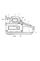
- FIG. 3A is a side view showing a reinforcing device with the cover open.
- FIG. 3B is a side view showing the reinforcing device when the cover is closed.
- FIG. 4 is a side view of the reinforcing device according to the comparative example.
- FIG. 5 is a plan view showing the fusion splicing device according to the second embodiment.
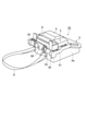
- FIG. 6 is a schematic rear perspective view showing a state in which accessories are attached to the fusion splicing device.
- FIG. 1A is a perspective view showing a fusion splicing device according to the first embodiment.
- FIG. 1B is a side view showing a fusion splicing device according to the first embodiment.
- FIG. 7A is a plan view showing a state in which accessories are attached to the fusion splicer.
- FIG. 7B is a plan view showing a state in which accessories are attached to the fusion splicer.
- FIG. 8 is a perspective view showing a multi-clamp in an open state.
- FIG. 9A is a schematic cross-sectional view showing a multi-clamp in an open state.
- FIG. 9B is a schematic cross-sectional view showing a rotating multi-clamp.
- the optical fiber fusion splicer may not be used in a stationary state (normal state) without tilting.
- a stationary state normal state
- the operator uses the optical fiber fusion splicing device while riding on a ladder truck or the like.
- the optical fiber fusion splicer may be used in a tilted state (special state) due to restrictions on the work space or the like.
- the lid of the optical fiber reinforcing heater is closed by its own weight, and the work efficiency of the connection work is lowered.
- An object of the present disclosure in view of such a problem is to provide a lid position holding mechanism, a reinforcing device, and an optical fiber fusion splicer capable of preventing the lid portion from closing due to its own weight.
- One embodiment of the present disclosure includes a main body, a lid that rotates and opens and closes with respect to the main body about a rotation axis, a fixed end fixed to the main body, an elastically deformable free end, and an elastically deformable free end. It is provided with an elastic member having a connecting portion for connecting the fixed end portion and the free end portion, and the free end portion can be elastically deformed with the connecting portion as a fulcrum, and the lid portion is changed from the open state to the closed state by its own weight. It is a lid position holding mechanism that keeps the open state of the lid portion by contacting the lid portion and the free end portion with each other when rotating so as to change.
- the elastic member may be a leaf spring.
- the lid portion is easily locked to the free end portion, so that the open state of the lid portion is well maintained.
- the lid has a protrusion that projects toward the free end when the lid is open and rotates so that the lid changes from the open state to the closed state under its own weight. At that time, the open state of the lid portion may be maintained by the free end portion and the protruding portion coming into contact with each other.
- One embodiment of the present disclosure is a reinforcing device for reinforcing a fusion-bonded connection portion between optical fibers, and is a heat-shrinkable tube that covers the lid position holding mechanism, the fusion-bonded connection portion, and the fusion-bonded connection portion.
- the accommodating portion, the heater that heats the heat-shrinkable tube accommodated in the accommodating portion, the optical fiber clamp having the first lid portion and holding the optical fiber in the accommodating portion, and the accommodating portion are opened or closed.
- a second lid portion is provided, and at least one of the first lid portion and the second lid portion is a reinforcing device included in the lid portion of the lid position holding mechanism.
- the reinforcing device includes an optical fiber clamp having the lid position holding mechanism and a second lid portion fixed to the first lid portion.
- the open state of the first lid portion and the second lid portion is held by the elastic member. The closure. Therefore, according to the above reinforcing device, it is possible to prevent the first lid portion and the second lid portion from closing due to their own weight.
- One embodiment of the present disclosure comprises a reinforcing device for reinforcing a fusion-bonded connection portion between optical fibers having a lid position holding mechanism, and a fusion-bonded processing portion for forming the fusion-bonded connection portion. It is a fiber fusion splicer. When this optical fiber fusion splicer is used, for example, in an inclined state, it is possible to prevent the lid portion from closing due to its own weight.
- This optical fiber fusion splicer further includes a housing provided with a reinforcing device and a fusion processing unit, an expansion member mounted on the housing, and a multi-clamp mounted on the expansion member.
- the third lid When the third lid is rotated by its own weight so as to change from the open state to the closed state, the third lid and the second free end are in contact with each other, so that the third lid is elastically deformable.
- the open state of the portion may be maintained. Since the multi-clamp has the same configuration as the lid position holding mechanism, it is possible to prevent the third lid portion from closing due to its own weight.
- the optical fiber fusion splicer has the above-mentioned lid position holding mechanism.
- FIG. 1A is a perspective view showing the fusion splicing device according to the first embodiment
- FIG. 1B is a side view showing the fusion splicing device according to the first embodiment.
- the fusion splicing device 1 shown in FIGS. 1A and 1B is a device (optical fiber fusion splicer) for fusion-bonding a pair of optical fibers (not shown).
- an optical fiber holder (not shown) is attached near the welded portion which is the tip end portion of each optical fiber.
- the front side of the fusion splicing device 1 is the front side of the device
- the back side of the fusion splicing device 1 is the rear side of the device.
- a fusion processing unit 3 for fusion-bonding optical fibers and a monitor 4 are provided on the upper portion of the housing 2 of the fusion-bonding device 1.
- the fusion treatment unit 3 is provided with a mounting unit on which an optical fiber holder can be mounted, a pair of fiber positioning units, and a pair of electrode rods.
- the welded portions fixed at the above-mentioned placement portion and positioned between the pair of electrode rods at the fiber positioning portion are fused and connected to each other by arc discharge.
- the monitor 4 is a part that displays the state of fusion splicing between optical fibers taken by a camera arranged inside the housing 2.
- the monitor 4 is located in front of the device from the fusion processing unit 3.
- the operator can carry out the fusion splicing work of the optical fiber while checking the monitor 4.
- the monitor 4 also functions as an operation unit for operating the fusion processing unit 3 and the like, and includes a touch panel. Therefore, the operator can operate the fusion splicing device 1 by touching the operation screen displayed on the monitor 4.
- the fusion treatment section 3 is covered with the windshield cover 5.
- the windshield cover 5 is a lid connected to the housing 2 so as to openably cover the fusion-bonded processing portion 3.
- the connecting portion 5a between the windshield cover 5 and the housing 2 includes a rotation shaft RA1 located between the fusion processing unit 3 and the monitor 4, and the windshield cover 5 is opened and closed along the rotation of the rotation shaft RA1.
- the windshield cover 5 is opened by rotating counterclockwise and closed by rotating clockwise. Can be placed in a closed state.
- the windshield cover 5 can be arranged in the open state by rotating along one direction of the rotation direction of the rotation shaft RA1, and is closed by rotating along the other direction of the above rotation directions.
- a state in which the lid of the windshield cover 5 or the like is opened by at least half or more is set as an open state, and a state in which the lid is completely closed is set as a closed state.
- the rotary shaft RA1 is rotatably supported with respect to the housing 2.
- one side surface 2a of the housing 2 is provided with an insertion port 6 into which an external recording medium or the like can be inserted.
- the external recording medium is, for example, a USB memory, an SD card, or the like.
- the insertion slot 6 is covered with the cover 6a.
- a power switch 7 and a power port 8 into which a power cable can be inserted are provided on the other side surface 2b of the housing 2.
- the insertion port 6, the power switch 7, and the power port 8 are located below the fusion processing unit 3.
- a reinforcing device 9 is provided at the upper part of the housing 2 and behind the device from the fusion processing unit 3.
- the reinforcing device 9 is a device for reinforcing a fusion-bonded connection portion between optical fibers.
- the reinforcing device 9 is a portion that heat-shrinks the heat-shrinkable tube that covers the fusion-bonded connection portion formed by the fusion-bonded processing portion 3.
- the reinforcing device 9 constitutes a part of the back surface of the fusion splicing device 1.
- FIG. 2 is a perspective view showing a reinforcing device.
- the reinforcing device 9 has a main body portion 11 extending from one side surface 2a of the fusion splicing device 1 to the other side surface 2b, and a cover 12 attached to the main body portion 11.
- Each of the main body portion 11 and the cover 12 is a molded body of a resin, a metal, an alloy, or the like, and is a rigid body.
- a housing portion 13 is provided in the central portion 11a of the main body portion 11.
- a clamp portion 14 (optical fiber clamp) is provided on one side surface 2a side of the accommodating portion 13.
- a clamp portion 15 (optical fiber clamp) is provided on the other side surface 2b side of the accommodating portion 13.
- a support portion 11b that rotatably supports the rotary shaft RA2 on which the cover 12 is mounted is provided behind the device in the central portion 11a.
- the accommodating portion 13 is a portion accommodating a heat-shrinkable tube and includes a heater 13a mounted on the central portion 11a.
- the heater 13a is a member that heats the heat-shrinkable tube housed in the housing portion 13.
- the heater 13a is, for example, a planar heating element having a U-shaped cross section or a V-shaped cross section, and extends from one side surface 2a side of the fusion splicing device 1 toward the other side surface 2b side.
- the central portion 11a is provided with a groove G for accommodating the optical fiber.
- the groove G extends from the one side surface 2a side toward the other side surface 2b side, and is open above the device. The surface of at least a part of the groove G is formed by the heater 13a.
- the groove G accommodates a fusion-bonded connection portion between optical fibers and a heat-shrinkable tube placed around the fusion-bonded connection portion.
- the heat shrinkable tube comes into contact with the heater 13a.
- the heater 13a in the accommodating portion 13 generates heat
- the heat-shrinkable tube heat-shrinks.
- the cover 12 is closed.
- Each of the pair of clamp portions 14 and 15 is a member for holding an optical fiber arranged in the reinforcing device 9.
- the clamp portions 14 and 15 are provided so as to sandwich the accommodating portion 13. According to FIGS. 1A and 1B, the clamp portion 14 is located on one side surface 2a side of the fusion splicing device 1, and the clamp portion 15 is located on the other side surface 2b side of the fusion splicing device 1.
- the clamp portions 14 and 15 have substantially the same configuration as each other. Therefore, in the following, the configuration of the clamp portion 14 will be mainly described. Further, regarding the clamp portion 15, only the portion different from the clamp portion 14 will be described.
- FIG. 3A is a side view showing the reinforcing device in the open state of the cover
- FIG. 3B is a side view showing the reinforcing device in the closed state of the cover.
- the clamp portion 14 has a first end portion 11c of the main body portion 11, a lid portion 12a (first lid portion) which is a part of the cover 12, and a first end. It has an elastic member 16 provided on the portion 11c.
- a mechanism cover position holding mechanism capable of holding at least the lid portion 12a in an open state is configured by the main body portion 11 including the first end portion 11c, the lid portion 12a, and the elastic member 16. The closure. Therefore, in the first embodiment, the clamp portion 14 includes the lid position holding mechanism.
- the first end portion 11c has a guide 21 for accommodating an optical fiber or an optical fiber holder, and a magnet 22 located in front of the guide 21.
- the guide 21 and the magnet 22 are arranged so as to face the lid portion 12a when the lid portion 12a is in the closed state.
- the guide 21 and the magnet 22 are provided at positions that can be visually recognized in a plan view when the lid portion 12a is in the open state.
- the guide 21 includes a switch 21a projecting from the surface of the first end portion 11c. When the switch 21a is pressed, it is determined that the optical fiber is properly clamped by the clamp portion 14.
- the switch 21a is connected to the control unit of the heater 13a, for example, through a conductor (not shown). In this case, depending on the state of the switch 21a, the heat treatment of the tube by the heater 13a may be automatically started, or the heat treatment may be feasible.
- the magnet 22 is a member for holding the closed state of the cover 12.
- the lid portion 12a is a member that rotates around the rotation shaft RA2 with respect to the main body portion 11 to open and close.
- the lid portion 12a is rotatably supported with the rotation shaft RA2 as a fulcrum.
- the lid portion 12a is fixed to the rotating shaft RA2 and can be opened and closed along the rotation of the rotating shaft RA2.
- the lid portion 12a is open to the first end portion 11c (see FIG. 3A) and closed to the first end portion 11c. It can be placed in a closed state (see FIG. 3B).
- the lid portion 12a When the fusion splicer 1 is observed from one side surface 2a side of the housing 2, the lid portion 12a is closed by rotating clockwise and opened by rotating counterclockwise.
- the lid portion 12a is integrated with another lid portion 12b (second lid portion) that covers the accommodating portion 13 of the cover 12. Therefore, the lid portion 12b opens or closes the accommodating portion 13 including the heater 13a in conjunction with the lid portion 12a.
- the lid portion 12b also rotates about the rotation shaft RA2 so as to change from the open state to the closed state.
- the lid portion 12b is detachably fixed to the lid portion 12a.
- the lid portion 12a has a clamper 31 for holding an optical fiber, a magnet 32 that can be attracted to the magnet 22, and a protruding portion 33.
- the clamper 31 is provided so as to sandwich the guide 21 when the lid portion 12a is in the closed state.
- An elastic member such as a spring is provided inside the clamper 31.
- the clamper 31 can apply an urging force to the optical fiber arranged on the guide 21, so that the optical fiber can be held satisfactorily.
- the magnets 22 and 32 are attracted to each other.
- the lid portion 12a is closed with the optical fiber arranged on the guide 21, the optical fiber is sandwiched and held by the guide 21 and the clamper 31.
- the switch 21a is pressed by the optical fiber.
- the magnets 22 and 32 maintain the pinching of the optical fiber between the guide 21 and the clamper 31. Therefore, the state in which the switch 21a is pressed by the optical fiber is maintained.
- the protruding portion 33 is a rigid body portion that comes into contact with the elastic member 16 when the lid portion 12a is opened and closed, and moves within a certain range in conjunction with the rotation of the lid portion 12a.
- the protruding portion 33 projects toward the elastic member 16 (particularly, the free end portion 42 described later) when the lid portion 12a is in the open state, and protrudes toward the rear of the device when the lid portion 12a is in the closed state. ..
- FIG. 3A when the lid 12a is open, at least a portion of the protrusion 33 is located below the device above the highest portion of the elastic member 16.
- the protruding portion 33 projects so as to be closer to the lower side of the device than the highest portion of the elastic member 16 when the lid portion 12a is in the open state.
- the protruding portion 33 is located in front of the device with respect to the rotation shaft RA2.
- the protruding portion 33 is located behind the device with respect to the rotation shaft RA2.
- the protrusion 33 has a first surface 33a that comes into contact with the elastic member 16 when the lid portion 12a rotates so as to change from the open state to the closed state, and the lid portion 12a rotates so as to change from the closed state to the open state.
- the "rigid body portion” means a portion that does not deform or substantially does not deform under the normally used environment of the fusion splicer 1.
- the elastic member 16 is a member for preventing at least the lid portion 12a from changing from the open state to the closed state due to its own weight.
- the elastic member 16 is provided on the first end portion 11c and behind the device 21. Further, the elastic member 16 is located below the rotation shaft RA2.
- the elastic member 16 is a work piece of a plate-shaped member such as a leaf spring, but the elastic member 16 is not limited to this.
- the elastic member 16 may be, for example, a torsion spring or the like.
- the elastic member 16 includes a fixed end portion 41 fixed to the main body portion 11 (first end portion 11c), an elastically deformable free end portion 42, and a connecting portion connecting the fixed end portion 41 and the free end portion 42. Has 43.
- the fixed end portion 41 is a plate-shaped portion fixed on the first end portion 11c, and extends from the rear of the device toward the front of the device.
- One end 41a of the fixed end 41 is a portion of the fixed end 41 located most in front of the device.
- One end 41a may be located in front of the device, for example, the rotation shaft RA2, and may be included in the connection portion 43.
- the other end 41b of the fixed end 41 is the portion of the fixed end 41 located most rearward of the device.
- the other end 41b is located behind the device, for example, the rotation shaft RA2. At least a part of the fixed end portion 41 may be inserted inside the first end portion 11c.
- the free end portion 42 is a portion of the elastic member 16 that exhibits elasticity, and extends from the connecting portion 43 toward the upper side of the device.
- the free end portion 42 extends above the device and extends from the front of the device to the rear of the device. At least a part of the free end portion 42 is located above the tip of the protrusion 33 and is located behind the device from the rotation shaft RA2. Further, the free end portion 42 extends toward the lid portion 12a when the lid portion 12a is in the open state. The free end portion 42 is separated from the lid portion 12a when the lid portion 12a is in the open state and the closed state, but the free end portion 42 is not limited to this.
- the free end portion 42 is elastically deformed so as to rotate with the connecting portion 43 as a fulcrum. For example, when a downward force (pushing pressure) is applied to the free end portion 42, at least a part of the free end portion 42 is elastically deformed so as to approach the fixed end portion 41. By eliminating the pressing force applied to the free end portion 42, at least a part of the free end portion 42 can be restored to its original position.
- the pressing force for elastically deforming the free end portion 42 is larger than the force corresponding to the total weight of the lid portions 12a and 12b.
- the free end portion 42 when a pressing force corresponding to the total weight of the lid portions 12a and 12b is applied to the free end portion 42, the free end portion 42 does not elastically deform or substantially does not elastically deform.
- the lids 12a and 12b rotate so as to change from the open state to the closed state due to the weight of the integrated lids 12a and 12b, the first surface 33a of the protrusion 33 is locked to the free end 42. ..
- the rotation of the lid portions 12a and 12b is stopped.
- the free end portion 42 supports the lid portions 12a and 12b via the protruding portion 33, the open state of the lid portions 12a and 12b is maintained.
- the elastic member 16 When a pressing force significantly larger than the force corresponding to the total weight of the lid portions 12a and 12b is applied to the free end portion 42 via the protruding portion 33, the elastic member 16 is elastically deformed. As a specific example, the free end portion 42 rotates so as to approach the fixed end portion 41 with the connecting portion 43 as a fulcrum. The rotation causes the free end 42 to be pushed out by the protrusion 33. As a result, for example, when the fusion splicer 1 is stationary, all of the free end portions 42 are located below the protrusion 33, so that the protrusion 33 is released from being locked by the free end portion 42. To. The lids 12a and 12b rotate so as to be in the closed state. At this time, since the pressing force applied from the protruding portion 33 to the free end portion 42 is reduced, the free end portion 42 is restored to the original position.
- the free end portion 42 is located behind the base end portion 42a which may be included in the connection portion 43, the main body portion 42b which is above the base end portion 42a and extends to the rear of the device, and the main body portion 42b. It has at least a part of the tip portion 42c and a bent portion 42d connecting the main body portion 42b and the tip portion 42c. A part of the main body portion 42b, the tip portion 42c, and the bent portion 42d are located on the orbit of the protruding portion 33.
- the main body portion 42b is a plate-shaped portion that comes into contact with the first surface 33a of the protruding portion 33 when the lid portion 12a rotates so as to change from the open state to the closed state.
- the tip portion 42c is a plate-shaped portion that comes into contact with the second surface 33b of the protruding portion 33 when the lid portion 12a rotates so as to change from the closed state to the open state. From the viewpoint of increasing the contact area with the second surface 33b, the tip portion 42c extends to the rear of the device and below the device. This makes it easier for the free end portion 42 to receive a force from the second surface 33b.
- the lid portion 12a rotates so as to change from the closed state to the open state, the free end portion 42 is less likely to hinder the rotation.
- the connecting portion 43 is a portion located at the boundary between the fixed end portion 41 and the free end portion 42.
- the connecting portion 43 is a bent portion in which a plate-shaped member that is the source of the elastic member 16 is bent.
- the clamp portion 15 is provided on the second end portion 11d of the main body portion 11, the lid portion 12c (first lid portion) which is a part of the cover 12, and the second end portion 11d, similarly to the clamp portion 14. It has an elastic member (not shown).
- the second end portion 11d unlike the first end portion 11c, does not have a guide 21.
- the lid portion 12c is a member that rotates around the rotation shaft RA2 and opens and closes with respect to the main body portion 11. Further, the lid portion 12c is not integrated with the lid portion 12b. Therefore, the lid portion 12c is independent of the lid portions 12a and 12b, and therefore is not interlocked with the opening / closing operation of the lid portions 12a and 12b.
- the elastic member included in the clamp portion 15 is the same member as the elastic member 16 of the clamp portion 14. Therefore, when the lid portion 12c rotates so as to change from the open state to the closed state due to its own weight, the elastic member and the lid portion 12c come into contact with each other, so that the open state of the lid portion 12c is maintained. That is, in the first embodiment, the clamp portion 15 includes a mechanism (cover position holding mechanism) capable of holding the lid portion 12c in the open state.
- FIG. 4 is a side view of the reinforcing device according to the comparative example.
- the reinforcing device 109 according to the comparative example does not have an elastic member for holding the lid portion 12a.
- the lid portion 12a rotates by its own weight. Then, the lid portion 12a may be closed at an unintended timing.
- the operator needs to move the fusion-bonded connection portion of the optical fiber from the fusion-bonded processing portion to the reinforcing device 109 while supporting the lid portion 12a. Therefore, in the special state, there is a problem that the efficiency of the reinforcement work of the fusion splicing portion is lowered.
- the reinforcing device 9 of the fusion splicing device 1 is provided with a lid position holding mechanism composed of an elastic member 16 and the like.
- the reinforcing device 9 is rotated so that the lid portion 12a is closed by its own weight. It may move.
- the free end portion 42 of the elastic member 16 and the lid portion 12a come into contact with each other, so that the open state of the lid portion 12a is maintained.
- the lid portion 12a is integrated with the lid portion 12b that opens or closes the accommodating portion 13 including the heater 13a. Therefore, it is possible to prevent the lid portions 12a and 12b from closing due to their own weight. As a result, the operator can move the fusion spliced portion of the optical fiber from the accommodating portion 13 to the reinforcing device 9 without interfering with the lid portion 12a. Therefore, by using the fusion splicing device 1, it is possible to satisfactorily suppress a decrease in efficiency of the reinforcement work of the fusion splicing portion even in the above special state.
- the reinforcing device 9 is included in the cover 12, and also includes the lid portion 12c that is independent of the lid portions 12a and 12b, and the open state of the lid portion 12c can also be held by the elastic member. be. Therefore, even when the fusion splicing device 1 is used in the above special state, the operator can easily keep the cover 12 including the lids 12a to 12c in the open state for the fusion splicing of the optical fiber. The portion can be moved from the accommodating portion 13 to the reinforcing device 9.
- the elastic member 16 may be a leaf spring.
- the lid portion 12a is easily locked to the free end portion 42, so that the open state of the lid portion 12a is well maintained.
- the lid portion 12a has a protruding portion 33 that protrudes toward the free end portion 42 when the lid portion 12a is in the open state, and the lid portion 12a is changed from the open state to the closed state by its own weight.
- the free end portion 42 and the protruding portion 33 come into contact with each other when rotating so as to change, the open state of the lid portion 12a is maintained.
- the lid portion 12b is opened in the open state. It may be provided with a mechanism that can be held (a lid position holding mechanism).
- FIG. 5 is a plan view showing the fusion splicing device according to the second embodiment.
- FIG. 6 is a schematic rear perspective view showing a state in which accessories are attached to the fusion splicing device according to the second embodiment.
- the fusion splicing device 1A includes an expansion member 50 mounted on the housing 2.
- the expansion member 50 is a member for mounting accessories (details will be described later) for the fusion splicer 1A.
- the expansion member 50 is provided on the back surface of the first portion 51 provided on one side surface 2a of the fusion splicing device 1A, the second portion 52 provided on the other side surface 2b of the fusion splicing device 1A, and the fusion splicing device 1A. It has a connecting portion 53 to be attached.
- Each of the first portion 51 and the second portion 52 is connected to the connecting portion 53. Therefore, each of the first portion 51, the second portion 52, and the connecting portion 53 is integrated.
- slots 54 and 55 are provided in the first portion 51.
- Each of the slots 54 and 55 is a portion that functions as an insertion port for accessories, and is a recess or an opening having a substantially square shape in a plan view.
- the slots 54 are provided so as to line up with the fusion splicer 3, and the slots 55 are provided so as to line up with the reinforcing device 9.
- the second portion 52 is provided with slots 56 and 57 in the same manner as the first portion 51.
- Each of the slots 56 and 57 is a portion that functions as an insertion port for accessories, and is a recess or an opening having a substantially square shape in a plan view.
- the slots 56 are provided so as to be lined up with the fusion splicer 3, and the slots 57 are provided so as to be lined up with the reinforcing device 9. Therefore, in a plan view, the fusion treatment unit 3 is located between the slots 54 and 56, and the reinforcing device 9 is located between the slots 55 and 57.
- a mounting portion 58 for mounting the strap S which is an example of the above accessories, is provided on the connecting portion 53.
- the mounting portion 58 is fixed to the connecting portion 53 via, for example, a fastening member.
- the strap S is used, for example, for an operator to hang the fusion splicing device 1A around his neck.
- the front surface of the device is located on the lower side and the back surface of the device is located on the upper side.
- FIGS. 7A and 7B are a plan view showing a state in which accessories are attached to the fusion splicing device 1A.
- the fusion splicing device 1A is equipped with the multi-clamps 61 and 62, which are another examples of the above accessories.
- Each of the multi-clamps 61 and 62 is a member for assisting the transportation of the optical fiber.
- the operator can easily carry the optical fiber from the fusion-bonding processing unit 3 to the reinforcing device 9. As a result, the optical fiber is less likely to be damaged during the transportation.
- the multi-clamp 61 is mounted on the expansion member 50 via the slot 54, and the multi-clamp 62 is mounted on the expansion member 50 via the slot 56. At this time, the fusion treatment unit 3 is arranged between the multi-clamps 61 and 62.
- the multi-clamp 61 is mounted on the expansion member 50 via the slot 55, and the multi-clamp 62 is mounted on the expansion member 50 via the slot 57. At this time, the reinforcing device 9 is arranged between the multi-clamps 61 and 62.
- Each of the multi-clamps 61 and 62 has a long side and a short side in a plan view.
- the long side extends along the direction from one side surface 2a to the other side surface 2b in the fusion splicer 1A, and the short side extends. It extends along the front-rear direction of the fusion splicer 1A.
- the long side direction and the short side direction may be used.
- FIGS. 8 and 9A and 9B are perspective views showing the multi-clamp in the open state
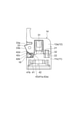
- FIG. 9A is a schematic cross-sectional view showing the multi-clamp in the open state
- FIG. 9B is a schematic cross-sectional view showing the rotating multi-clamp. .. As shown in FIGS.
- the multi-clamp 61 includes a rotary shaft RA3, a main body portion 63 that rotatably supports the rotary shaft RA3, a lid portion 64 fixed to the rotary shaft RA3, and a main body portion 63. It has an elastic member 65 fixed to the.
- the rotary shaft RA3 is located at the rear of the device.
- the main body portion 63, the lid portion 64, and the elastic member 65 form a mechanism (cover position holding mechanism) capable of holding the lid portion 64 in the open state.
- the main body portion 63 is provided on the base portion 71, the first support portion 72 provided on the base portion 71 and supporting one end of the rotating shaft RA3, and the other end of the rotating shaft RA3 provided on the base portion 71.
- the base portion 71 is a portion in which the optical fiber is placed in the main body portion 63.
- the base portion 71 is provided with a mounting portion 71a for mounting the optical fiber.
- the mounting portion 71a is a portion recessed from the surface SU1 of the base portion 71. When the lid portion 64 is in the closed state, the mounting portion 71a faces the lid portion 64. In a plan view, the mounting portion 71a is located between the first support portion 72 and the second support portion 73 in the long side direction.
- the first support portion 72 is located on one side of the mounting portion 71a in the long side direction, and protrudes from the surface SU1 of the base portion 71.
- the first support portion 72 is provided with a groove 72a extending in the long side direction.
- the groove 72a is a portion in which the optical fiber is housed, and overlaps the mounting portion 71a in the long side direction.
- the second support portion 73 is located on the opposite side of the mounting portion 71a in the long side direction and protrudes from the surface SU1.
- the second support portion 73 is provided with a groove 73a extending in the long side direction.
- the groove 73a is a portion in which the optical fiber is housed like the groove 72a, and overlaps the mounting portion 71a in the long side direction. Therefore, when the optical fiber is mounted on the multi-clamp 61, the optical fiber is mounted on the mounting portion 71a and is accommodated in the grooves 72a and 73a.
- Each of the first convex portion 74 and the second convex portion 75 is a male portion that can be inserted into slots 54 to 57 (see FIG. 5) of the expansion member 50, and protrudes from the bottom surface SU2 of the base portion 71.
- the first convex portion 74 extends along one end of the base portion 71 in the long side direction
- the second convex portion 75 extends along the other end of the base portion 71 in the long side direction.
- each of the tip 74a of the first convex portion 74 and the tip 75a of the second convex portion 75 has a tapered shape.
- the magnet 76 is a member for holding the closed state of the lid portion 64, and is located on the opposite side of the rotation shaft RA3 with the mounting portion 71a interposed therebetween.
- the lid portion 64 is a member that can be opened and closed along the rotation of the rotation shaft RA3. By rotating the lid portion 64 along the rotation shaft RA3, the lid portion 64 can be arranged in an open state open with respect to the main body portion 63 and a closed state closed with respect to the main body portion 63.
- the lid portion 64 rotates in the same manner as the cover 12 of the reinforcing device 9.
- the lid portion 64 is closed by rotating along one of the rotation directions of the rotation shaft RA1 and is closed along the other direction of the rotation direction. It is released by rotating.
- the lid portion 64 has a clamper 81 for holding an optical fiber, a magnet 82 that can contact the magnet 76, and a protruding portion 83.
- the clamper 81 is a member facing the mounting portion 71a when the lid portion 64 is in the closed state, and exhibits the same function as the clamper 31 included in the lid portion 12a of the reinforcing device 9. Therefore, an elastic member such as a spring is provided inside the clamper 81. As a result, the clamper 81 can apply an urging force to the optical fiber mounted on the mounting portion 71a, so that the optical fiber can be held satisfactorily.
- the magnets 76 and 82 are attracted to each other. As a result, by closing the lid portion 64 with the optical fiber arranged in the mounting portion 71a, the optical fiber is sandwiched and held by the mounting portion 71a and the clamper 81.
- the protruding portion 83 is a rigid body portion that comes into contact with the elastic member 65 when the lid portion 64 is opened and closed, and exhibits the same function as the protruding portion 33 included in the lid portion 12a of the reinforcing device 9.
- the protruding portion 83 is interlocked with the rotation of the lid portion 64.
- the protrusion 83 projects toward the elastic member 65 when the lid 64 is in the open state. As shown in FIG. 9A, when the lid portion 64 is in the open state, at least a part of the protruding portion 83 is located on the bottom surface SU2 side of the base portion 71 with respect to the highest portion of the elastic member 65.
- the projecting portion 83 projects so as to reach the lower side of the device with respect to the highest portion of the elastic member 65 when the lid portion 64 is in the open state.
- the protrusion 83 has a first surface 83a that comes into contact with the elastic member 65 when the lid portion 64 rotates from the open state to the closed state, and the lid portion 64 rotates so as to change from the closed state to the open state. It has a second surface 83b that comes into contact with the elastic member 65.
- the first surface 83a is located on the upper side of the device with respect to the second surface 83b.
- the elastic member 65 is a member for preventing the lid portion 64 from changing from the open state to the closed state due to its own weight, and exhibits the same function as the elastic member 16 included in the reinforcing device 9.
- a part of the elastic member 65 is located on the bottom surface SU2 of the base portion 71, and the other portion of the elastic member 65 is located on the surface SU1 of the base portion 71.
- the elastic member 65 is a work piece of a plate-shaped member such as a leaf spring like the elastic member 16, but is not limited to this.
- the elastic member 65 has a fixed end portion 91 fixed in the base portion 71, an elastically deformable free end portion 92, and a connecting portion 93 connecting the fixed end portion 91 and the free end portion 92.
- the fixed end portion 91 is a plate-shaped portion fixed to the bottom surface SU2 of the base portion 71, and extends from the magnet 76 side toward the rotation shaft RA3 side in the short side direction.
- One end 91a of the fixed end 91 is located closest to the rotation axis RA3 in the short side direction.
- the other end 91b of the fixed end 91 is located closer to the magnet 76 than one end 91a in the short side direction.
- the free end portion 92 is a portion of the elastic member 65 that exhibits elasticity, and extends from the connecting portion 93 toward the surface SU1 of the base portion 71.
- the free end portion 92 is separated from the lid portion 64 when the lid portion 64 is in the open state and the closed state, but the free end portion 92 is not limited to this.
- the free end portion 92 is elastically deformed so as to rotate with the connecting portion 93 as a fulcrum. For example, when a force (pushing pressure) is applied to the free end portion 92, at least a part of the free end portion 42 is elastically deformed. By not applying the pressing force to the free end portion 92, at least a part of the free end portion 92 is restored to the original position.
- the pressing force for elastically deforming the free end portion 92 is larger than the force corresponding to the weight of the lid portion 64.
- the free end portion 92 does not elastically deform or substantially does not elastically deform.
- the free end portion 92 supports the lid portion 64 via the protruding portion 83, the open state of the lid portion 64 is maintained.
- the elastic member 65 is elastically deformed. Specifically, the free end portion 92 rotates so as to approach the fixed end portion 91 with the connecting portion 93 as a fulcrum. By the rotation, all of the free end portions 92 are located below the protrusions 83, so that the protrusions 83 are released from being locked by the free end portions 92. As a result, the lid portion 64 is rotated so as to be in the closed state. At this time, since the pressing force applied from the protruding portion 83 to the free end portion 92 is reduced, the free end portion 92 is restored to the original position.
- the free end portion 92 includes a base end portion 92a that may be included in the connection portion 93, a main body portion 92b that extends from the base end portion 92a toward the rotation shaft RA3, and a tip portion that extends away from the rotation shaft RA3. It has a 92c and a bent portion 92d connecting the main body portion 92b and the tip portion 92c.
- a part of the main body portion 92b, the tip portion 92c, and the bent portion 92d are located on the surface SU1 of the base portion 71, and the trajectory of the protruding portion 83. Located on top.
- the main body portion 92b is a plate-shaped portion that comes into contact with the first surface 83a of the protruding portion 83 when the lid portion 64 is rotated so as to change from the open state to the closed state.
- the main body portion 92b is inclined with respect to the fixed end portion 91, and the angle formed by the main body portion 92b and the fixed end portion 91 is, for example, 90 ° or more and 135 °.
- the tip portion 92c is a plate-shaped portion that comes into contact with the second surface 83b of the protruding portion 83 when the lid portion 64 is rotated so as to change from the closed state to the open state.
- the contact area between the free end portion 92 and the second surface 83b can be increased, so that the free end portion 92 is more likely to receive a force from the second surface 83b. Therefore, when the lid portion 64 rotates so as to change from the closed state to the open state, the free end portion 92 is less likely to hinder the rotation.
- the connecting portion 93 is a portion located at the boundary between the fixed end portion 91 and the free end portion 92.
- the connecting portion 93 is a bent portion in which the plate-shaped member that is the source of the elastic member 65 is bent.
- each of the multi-clamps 61 and 62 includes a lid position holding mechanism similar to that of the reinforcing device 9 in the first embodiment.
- the lid portion 64 of the multi-clamp 61 automatically rotates so as to be closed by its own weight.
- the lid portion 64 is supported by the elastic member 65, it is possible to prevent the lid portion 64 from being automatically closed.
- the cover 12 of the reinforcing device 9 it is also possible to prevent the cover 12 of the reinforcing device 9 from being automatically closed.
- the lid position holding mechanism, the reinforcing device, and the optical fiber fusion splicer according to the present disclosure are not limited to the above-described embodiment, and various other modifications are possible.
- the elastic member is elastically deformed so as to rotate with the connecting portion as a fulcrum, but the present invention is not limited to this.
- the elastic member may be elastically deformed to be compressed instead of rotated, or may be elastically deformed to be rotated and compressed.
- the connecting portion of the elastic member is a bent portion, but the present invention is not limited to this.
- optical fiber fusion splicer according to the present disclosure is not limited to the above-described embodiment, and various other modifications are possible.
- the optical fiber fusion splicer has various lids other than those described in the above embodiment, and any of these lids can be provided with the lid position holding mechanism according to the present disclosure.
- the optical fiber fusion splicer may be provided with the lid position holding mechanism according to the present disclosure in addition to the reinforcing device.
- 1,1A ... Fusion connection device 2 ... Housing, 2a ... One side, 2b ... Other side, 3 ... Fusion processing unit, 4 ... Monitor, 5 ... Windshield cover, 5a ... Connection part, 6 ... Insertion port, 6a ... cover, 7 ... power switch, 8 ... power port, 9 ... reinforcement, 11 ... main body part, 11a ... central part, 11b ... support part, 11c ... first end part, 11d ... second end part, 12 ... Cover, 12a ... lid (first lid), 12b ... lid (second lid), 12c ... lid (first lid), 13 ... accommodating, 13a ... heater, 14, 15 ... clamp (Optical fiber clamp), 16 ... Elastic member, 21 ...
Landscapes
- Physics & Mathematics (AREA)
- Engineering & Computer Science (AREA)
- Plasma & Fusion (AREA)
- General Physics & Mathematics (AREA)
- Optics & Photonics (AREA)
- Mechanical Coupling Of Light Guides (AREA)
Priority Applications (3)
| Application Number | Priority Date | Filing Date | Title |
|---|---|---|---|
| CN202180047511.7A CN115769115A (zh) | 2020-08-07 | 2021-07-30 | 盖位置保持机构、加强器以及光纤熔接机 |
| JP2022541512A JPWO2022030403A1 (https=) | 2020-08-07 | 2021-07-30 | |
| KR1020237001764A KR20230043827A (ko) | 2020-08-07 | 2021-07-30 | 덮개 위치 보지 기구, 보강기, 및 광섬유 융착 접속기 |
Applications Claiming Priority (2)
| Application Number | Priority Date | Filing Date | Title |
|---|---|---|---|
| JP2020-134951 | 2020-08-07 | ||
| JP2020134951 | 2020-08-07 |
Publications (1)
| Publication Number | Publication Date |
|---|---|
| WO2022030403A1 true WO2022030403A1 (ja) | 2022-02-10 |
Family
ID=80118764
Family Applications (1)
| Application Number | Title | Priority Date | Filing Date |
|---|---|---|---|
| PCT/JP2021/028436 Ceased WO2022030403A1 (ja) | 2020-08-07 | 2021-07-30 | 蓋位置保持機構、補強器、及び光ファイバ融着接続機 |
Country Status (4)
| Country | Link |
|---|---|
| JP (1) | JPWO2022030403A1 (https=) |
| KR (1) | KR20230043827A (https=) |
| CN (1) | CN115769115A (https=) |
| WO (1) | WO2022030403A1 (https=) |
Citations (8)
| Publication number | Priority date | Publication date | Assignee | Title |
|---|---|---|---|---|
| JPS5937043U (ja) * | 1982-09-02 | 1984-03-08 | 株式会社東芝 | 保温釜などの蓋装置 |
| JPS6316939U (https=) * | 1986-07-21 | 1988-02-04 | ||
| JP2005321644A (ja) * | 2004-05-10 | 2005-11-17 | Fujikura Ltd | 光ファイバの補強スリーブ加熱装置 |
| JP2006215268A (ja) * | 2005-02-03 | 2006-08-17 | Furukawa Electric Co Ltd:The | 補強スリーブ加熱装置 |
| US20070039131A1 (en) * | 2005-08-16 | 2007-02-22 | Torqmaster, Inc. | Pop-up hinge with leaf spring |
| JP2009086104A (ja) * | 2007-09-28 | 2009-04-23 | Sanyo Electric Co Ltd | 開閉回動する突出体を具えた機器 |
| JP2012173372A (ja) * | 2011-02-18 | 2012-09-10 | Sei Optifrontier Co Ltd | 融着部の補強方法及び融着接続機 |
| JP2014119513A (ja) * | 2012-12-13 | 2014-06-30 | Fujikura Ltd | 光ファイバ融着接続機 |
Family Cites Families (4)
| Publication number | Priority date | Publication date | Assignee | Title |
|---|---|---|---|---|
| JP2007065026A (ja) * | 2005-08-29 | 2007-03-15 | Furukawa Electric Co Ltd:The | 熱収縮スリーブ加熱装置、それを用いた光ファイバ融着接続機、及び光ファイバ融着接続補強方法 |
| JP5309403B2 (ja) | 2010-12-24 | 2013-10-09 | Seiオプティフロンティア株式会社 | 光ファイバ補強用加熱器及び光ファイバ融着接続装置 |
| JP2013114135A (ja) * | 2011-11-30 | 2013-06-10 | Sei Optifrontier Co Ltd | 光ファイバ融着接続部の補強装置及び融着接続機 |
| JP6628247B2 (ja) * | 2016-05-19 | 2020-01-08 | Seiオプティフロンティア株式会社 | 光ファイバ融着接続部の補強装置およびそれを備えた融着接続機 |
-
2021
- 2021-07-30 JP JP2022541512A patent/JPWO2022030403A1/ja active Pending
- 2021-07-30 WO PCT/JP2021/028436 patent/WO2022030403A1/ja not_active Ceased
- 2021-07-30 KR KR1020237001764A patent/KR20230043827A/ko not_active Ceased
- 2021-07-30 CN CN202180047511.7A patent/CN115769115A/zh active Pending
Patent Citations (8)
| Publication number | Priority date | Publication date | Assignee | Title |
|---|---|---|---|---|
| JPS5937043U (ja) * | 1982-09-02 | 1984-03-08 | 株式会社東芝 | 保温釜などの蓋装置 |
| JPS6316939U (https=) * | 1986-07-21 | 1988-02-04 | ||
| JP2005321644A (ja) * | 2004-05-10 | 2005-11-17 | Fujikura Ltd | 光ファイバの補強スリーブ加熱装置 |
| JP2006215268A (ja) * | 2005-02-03 | 2006-08-17 | Furukawa Electric Co Ltd:The | 補強スリーブ加熱装置 |
| US20070039131A1 (en) * | 2005-08-16 | 2007-02-22 | Torqmaster, Inc. | Pop-up hinge with leaf spring |
| JP2009086104A (ja) * | 2007-09-28 | 2009-04-23 | Sanyo Electric Co Ltd | 開閉回動する突出体を具えた機器 |
| JP2012173372A (ja) * | 2011-02-18 | 2012-09-10 | Sei Optifrontier Co Ltd | 融着部の補強方法及び融着接続機 |
| JP2014119513A (ja) * | 2012-12-13 | 2014-06-30 | Fujikura Ltd | 光ファイバ融着接続機 |
Also Published As
| Publication number | Publication date |
|---|---|
| JPWO2022030403A1 (https=) | 2022-02-10 |
| CN115769115A (zh) | 2023-03-07 |
| KR20230043827A (ko) | 2023-03-31 |
Similar Documents
| Publication | Publication Date | Title |
|---|---|---|
| CN103282810B (zh) | 光纤熔接连接装置 | |
| CN102893190B (zh) | 光纤加固用加热器以及光纤熔融连接装置 | |
| CN103229082B (zh) | 光纤熔接机 | |
| JP6628247B2 (ja) | 光ファイバ融着接続部の補強装置およびそれを備えた融着接続機 | |
| WO2011052633A1 (ja) | フェルールホルダ | |
| CN103733101A (zh) | 熔接机 | |
| WO2010104133A1 (ja) | 光ファイバホルダ及び融着接続機 | |
| JP6442802B2 (ja) | 光ファイバホルダおよび当該光ファイバホルダを備えた融着接続装置 | |
| WO2022030403A1 (ja) | 蓋位置保持機構、補強器、及び光ファイバ融着接続機 | |
| JP2011090039A (ja) | 融着接続機 | |
| JP7015329B2 (ja) | 検眼用レンズユニットおよび検眼用レンズセット | |
| US20030059193A1 (en) | Optical fiber locking device for fusion splicing | |
| JP3863918B2 (ja) | 閉鎖式眼鏡ケース | |
| US12197010B2 (en) | Reinforcement sleeve heating device and fusion splicing machine | |
| US20090232457A1 (en) | Splicer with Splicing Cassette Carrier | |
| JP4149908B2 (ja) | ミラーホルダ及び風防カバー | |
| JP4163181B2 (ja) | 補強スリーブ加熱装置 | |
| JP2006171132A (ja) | 光ファイバ接続部補強スリーブの加熱方法及びそれに用いる加熱装置 | |
| JP2551359Y2 (ja) | 光ファイバの融着接続機 | |
| WO2025246264A1 (zh) | 铰链模组和眼镜 | |
| JPH04333957A (ja) | 情報処理装置 | |
| WO2025246263A1 (zh) | 眼镜和ar设备 | |
| JP2026507652A (ja) | 融着接続機 | |
| JP2002000335A (ja) | まつげ手入れ用具 | |
| JP2013114135A (ja) | 光ファイバ融着接続部の補強装置及び融着接続機 |
Legal Events
| Date | Code | Title | Description |
|---|---|---|---|
| 121 | Ep: the epo has been informed by wipo that ep was designated in this application |
Ref document number: 21853143 Country of ref document: EP Kind code of ref document: A1 |
|
| ENP | Entry into the national phase |
Ref document number: 2022541512 Country of ref document: JP Kind code of ref document: A |
|
| NENP | Non-entry into the national phase |
Ref country code: DE |
|
| 122 | Ep: pct application non-entry in european phase |
Ref document number: 21853143 Country of ref document: EP Kind code of ref document: A1 |