WO2022030341A1 - 射出成形機の操作パネル - Google Patents
射出成形機の操作パネル Download PDFInfo
- Publication number
- WO2022030341A1 WO2022030341A1 PCT/JP2021/028007 JP2021028007W WO2022030341A1 WO 2022030341 A1 WO2022030341 A1 WO 2022030341A1 JP 2021028007 W JP2021028007 W JP 2021028007W WO 2022030341 A1 WO2022030341 A1 WO 2022030341A1
- Authority
- WO
- WIPO (PCT)
- Prior art keywords
- button
- target
- molding machine
- drive target
- injection molding
- Prior art date
- Legal status (The legal status is an assumption and is not a legal conclusion. Google has not performed a legal analysis and makes no representation as to the accuracy of the status listed.)
- Ceased
Links
Images








Classifications
-
- G—PHYSICS
- G06—COMPUTING OR CALCULATING; COUNTING
- G06F—ELECTRIC DIGITAL DATA PROCESSING
- G06F3/00—Input arrangements for transferring data to be processed into a form capable of being handled by the computer; Output arrangements for transferring data from processing unit to output unit, e.g. interface arrangements
- G06F3/01—Input arrangements or combined input and output arrangements for interaction between user and computer
- G06F3/048—Interaction techniques based on graphical user interfaces [GUI]
- G06F3/0487—Interaction techniques based on graphical user interfaces [GUI] using specific features provided by the input device, e.g. functions controlled by the rotation of a mouse with dual sensing arrangements, or of the nature of the input device, e.g. tap gestures based on pressure sensed by a digitiser
- G06F3/0488—Interaction techniques based on graphical user interfaces [GUI] using specific features provided by the input device, e.g. functions controlled by the rotation of a mouse with dual sensing arrangements, or of the nature of the input device, e.g. tap gestures based on pressure sensed by a digitiser using a touch-screen or digitiser, e.g. input of commands through traced gestures
-
- G—PHYSICS
- G06—COMPUTING OR CALCULATING; COUNTING
- G06F—ELECTRIC DIGITAL DATA PROCESSING
- G06F3/00—Input arrangements for transferring data to be processed into a form capable of being handled by the computer; Output arrangements for transferring data from processing unit to output unit, e.g. interface arrangements
- G06F3/01—Input arrangements or combined input and output arrangements for interaction between user and computer
- G06F3/048—Interaction techniques based on graphical user interfaces [GUI]
- G06F3/0484—Interaction techniques based on graphical user interfaces [GUI] for the control of specific functions or operations, e.g. selecting or manipulating an object, an image or a displayed text element, setting a parameter value or selecting a range
- G06F3/04842—Selection of displayed objects or displayed text elements
-
- B—PERFORMING OPERATIONS; TRANSPORTING
- B29—WORKING OF PLASTICS; WORKING OF SUBSTANCES IN A PLASTIC STATE IN GENERAL
- B29C—SHAPING OR JOINING OF PLASTICS; SHAPING OF MATERIAL IN A PLASTIC STATE, NOT OTHERWISE PROVIDED FOR; AFTER-TREATMENT OF THE SHAPED PRODUCTS, e.g. REPAIRING
- B29C45/00—Injection moulding, i.e. forcing the required volume of moulding material through a nozzle into a closed mould; Apparatus therefor
- B29C45/17—Component parts, details or accessories; Auxiliary operations
- B29C45/1774—Display units or mountings therefor; Switch cabinets
-
- B—PERFORMING OPERATIONS; TRANSPORTING
- B29—WORKING OF PLASTICS; WORKING OF SUBSTANCES IN A PLASTIC STATE IN GENERAL
- B29C—SHAPING OR JOINING OF PLASTICS; SHAPING OF MATERIAL IN A PLASTIC STATE, NOT OTHERWISE PROVIDED FOR; AFTER-TREATMENT OF THE SHAPED PRODUCTS, e.g. REPAIRING
- B29C45/00—Injection moulding, i.e. forcing the required volume of moulding material through a nozzle into a closed mould; Apparatus therefor
- B29C45/17—Component parts, details or accessories; Auxiliary operations
- B29C45/76—Measuring, controlling or regulating
-
- B—PERFORMING OPERATIONS; TRANSPORTING
- B29—WORKING OF PLASTICS; WORKING OF SUBSTANCES IN A PLASTIC STATE IN GENERAL
- B29C—SHAPING OR JOINING OF PLASTICS; SHAPING OF MATERIAL IN A PLASTIC STATE, NOT OTHERWISE PROVIDED FOR; AFTER-TREATMENT OF THE SHAPED PRODUCTS, e.g. REPAIRING
- B29C45/00—Injection moulding, i.e. forcing the required volume of moulding material through a nozzle into a closed mould; Apparatus therefor
- B29C45/17—Component parts, details or accessories; Auxiliary operations
- B29C45/76—Measuring, controlling or regulating
- B29C45/766—Measuring, controlling or regulating the setting or resetting of moulding conditions, e.g. before starting a cycle
-
- G—PHYSICS
- G06—COMPUTING OR CALCULATING; COUNTING
- G06F—ELECTRIC DIGITAL DATA PROCESSING
- G06F3/00—Input arrangements for transferring data to be processed into a form capable of being handled by the computer; Output arrangements for transferring data from processing unit to output unit, e.g. interface arrangements
- G06F3/01—Input arrangements or combined input and output arrangements for interaction between user and computer
- G06F3/048—Interaction techniques based on graphical user interfaces [GUI]
- G06F3/0481—Interaction techniques based on graphical user interfaces [GUI] based on specific properties of the displayed interaction object or a metaphor-based environment, e.g. interaction with desktop elements like windows or icons, or assisted by a cursor's changing behaviour or appearance
-
- G—PHYSICS
- G06—COMPUTING OR CALCULATING; COUNTING
- G06F—ELECTRIC DIGITAL DATA PROCESSING
- G06F3/00—Input arrangements for transferring data to be processed into a form capable of being handled by the computer; Output arrangements for transferring data from processing unit to output unit, e.g. interface arrangements
- G06F3/01—Input arrangements or combined input and output arrangements for interaction between user and computer
- G06F3/048—Interaction techniques based on graphical user interfaces [GUI]
- G06F3/0484—Interaction techniques based on graphical user interfaces [GUI] for the control of specific functions or operations, e.g. selecting or manipulating an object, an image or a displayed text element, setting a parameter value or selecting a range
- G06F3/04847—Interaction techniques to control parameter settings, e.g. interaction with sliders or dials
-
- G—PHYSICS
- G06—COMPUTING OR CALCULATING; COUNTING
- G06F—ELECTRIC DIGITAL DATA PROCESSING
- G06F3/00—Input arrangements for transferring data to be processed into a form capable of being handled by the computer; Output arrangements for transferring data from processing unit to output unit, e.g. interface arrangements
- G06F3/01—Input arrangements or combined input and output arrangements for interaction between user and computer
- G06F3/048—Interaction techniques based on graphical user interfaces [GUI]
- G06F3/0487—Interaction techniques based on graphical user interfaces [GUI] using specific features provided by the input device, e.g. functions controlled by the rotation of a mouse with dual sensing arrangements, or of the nature of the input device, e.g. tap gestures based on pressure sensed by a digitiser
- G06F3/0488—Interaction techniques based on graphical user interfaces [GUI] using specific features provided by the input device, e.g. functions controlled by the rotation of a mouse with dual sensing arrangements, or of the nature of the input device, e.g. tap gestures based on pressure sensed by a digitiser using a touch-screen or digitiser, e.g. input of commands through traced gestures
- G06F3/04883—Interaction techniques based on graphical user interfaces [GUI] using specific features provided by the input device, e.g. functions controlled by the rotation of a mouse with dual sensing arrangements, or of the nature of the input device, e.g. tap gestures based on pressure sensed by a digitiser using a touch-screen or digitiser, e.g. input of commands through traced gestures for inputting data by handwriting, e.g. gesture or text
-
- G—PHYSICS
- G06—COMPUTING OR CALCULATING; COUNTING
- G06F—ELECTRIC DIGITAL DATA PROCESSING
- G06F3/00—Input arrangements for transferring data to be processed into a form capable of being handled by the computer; Output arrangements for transferring data from processing unit to output unit, e.g. interface arrangements
- G06F3/01—Input arrangements or combined input and output arrangements for interaction between user and computer
- G06F3/048—Interaction techniques based on graphical user interfaces [GUI]
- G06F3/0487—Interaction techniques based on graphical user interfaces [GUI] using specific features provided by the input device, e.g. functions controlled by the rotation of a mouse with dual sensing arrangements, or of the nature of the input device, e.g. tap gestures based on pressure sensed by a digitiser
- G06F3/0488—Interaction techniques based on graphical user interfaces [GUI] using specific features provided by the input device, e.g. functions controlled by the rotation of a mouse with dual sensing arrangements, or of the nature of the input device, e.g. tap gestures based on pressure sensed by a digitiser using a touch-screen or digitiser, e.g. input of commands through traced gestures
- G06F3/04886—Interaction techniques based on graphical user interfaces [GUI] using specific features provided by the input device, e.g. functions controlled by the rotation of a mouse with dual sensing arrangements, or of the nature of the input device, e.g. tap gestures based on pressure sensed by a digitiser using a touch-screen or digitiser, e.g. input of commands through traced gestures by partitioning the display area of the touch-screen or the surface of the digitising tablet into independently controllable areas, e.g. virtual keyboards or menus
-
- B—PERFORMING OPERATIONS; TRANSPORTING
- B29—WORKING OF PLASTICS; WORKING OF SUBSTANCES IN A PLASTIC STATE IN GENERAL
- B29C—SHAPING OR JOINING OF PLASTICS; SHAPING OF MATERIAL IN A PLASTIC STATE, NOT OTHERWISE PROVIDED FOR; AFTER-TREATMENT OF THE SHAPED PRODUCTS, e.g. REPAIRING
- B29C45/00—Injection moulding, i.e. forcing the required volume of moulding material through a nozzle into a closed mould; Apparatus therefor
- B29C45/17—Component parts, details or accessories; Auxiliary operations
- B29C45/76—Measuring, controlling or regulating
- B29C2045/7606—Controlling or regulating the display unit
Definitions
- the present invention relates to an operation panel of an injection molding machine.
- touch-operated operation panels are known (for example, Japanese Patent Publication No. 07-004845).
- the touch-operated operation panel may recognize operations not intended by the operator.
- the causes include, for example, a malfunction by the operator and a malfunction of the touch panel.
- the drive target of the injection molding machine performs an operation not intended by the operator.
- the present invention aims to solve the above-mentioned problems.
- An aspect of the present invention is an operation panel of an injection molding machine, which has a display screen, a target selection button for selecting a drive target of the injection molding machine, and an operation start button for starting the operation of the drive target.
- the operation is started in a state where the display unit to be displayed on the screen, the touch panel provided on the display screen and detecting the touch position on the display screen of the operator, and the target selection button are touched and the touch is maintained.
- the operation recognition unit that recognizes that the start of the operation of the drive target selected by the target selection button is instructed is provided.
- the risk of malfunction of the drive target is reduced.
- FIG. 1 It is a schematic block diagram of an injection device. It is a figure which illustrates the display screen of the operation panel applied to the operation of the forward movement of a screw. It is a figure which illustrates the display screen of the operation panel applied to the operation of the rotation of a screw. It is a schematic diagram which illustrates the mold rotating apparatus. It is a figure which illustrates the display screen of the operation panel applied to the rotation operation of a mold. It is a schematic block diagram of a robot provided in an injection molding machine. It is a figure which illustrates the display screen of the operation panel applied to the operation of a robot. It is a flowchart which illustrates the flow of the recognition process of the start instruction and the stop instruction of the operation of the drive target by the operation recognition part of the modification 2.
- FIG. 1 It is a schematic block diagram of an injection device. It is a figure which illustrates the display screen of the operation panel applied to the operation of the forward movement of a screw. It is a figure which illustrates the display screen of the operation panel applied to the
- FIG. 18A is a first diagram for explaining a procedure for selecting a drive target in the second modification.
- FIG. 18B is a second diagram for explaining a procedure for selecting a drive target in the second modification. It is a figure which illustrates the display screen of the operation panel of the modification 5. It is a figure which illustrates the display screen of the operation panel of the modification 7.
- FIG. 1 is a block diagram of an injection molding machine 12 to which the operation panel 10 of the embodiment is applied.
- the opening direction and the closing direction indicated by the arrows in FIG. 1 are opposite directions to each other. In this embodiment, both the open direction and the closed direction are horizontally parallel.
- the injection molding machine 12 to which the operation panel 10 of the present embodiment is applied will be described with reference to FIG.
- the injection molding machine 12 includes a mold 14, a mold clamping device 16, a machine base 18, and a control device 20.
- the mold 14 has a fixed mold 22 and a movable mold 24.
- the fixed mold 22 is installed on the machine base 18 so as not to move in the opening / closing direction.
- the movable mold 24 is installed on the machine base 18 so as to be movable along the opening / closing direction.
- the mold clamping device 16 is a device that moves the movable mold 24 along the opening / closing direction.
- the mold clamping device 16 is installed on the machine base 18.
- the mold clamping device 16 includes a fixed platen 26 and a movable platen 28.
- the fixed platen 26 supports the fixed mold 22 via the mounting plate 102.
- the movable platen 28 supports the movable mold 24 via the mounting plate 104.
- the mold clamping device 16 further includes a mold opening / closing mechanism 30, a rear platen 32, and a plurality of tie bars 33.
- the mold opening / closing mechanism 30 moves the movable platen 28 along the opening / closing direction.
- the movable mold 24 moves together with the movable platen 28.
- the rear platen 32 is installed at a position away from the movable platen 28 in the opening direction.
- the plurality of tie bars 33 connect the fixed platen 26 and the rear platen 32.
- the mold opening / closing mechanism 30 is a toggle type opening / closing mechanism in the present embodiment. That is, the mold opening / closing mechanism 30 includes a crosshead 36, a nut 38, and a ball screw 40.
- the crosshead 36 is connected to the movable platen 28 via a toggle link 34.
- the nut 38 is connected to the crosshead 36.
- a nut 38 is screwed into the ball screw 40.
- the axial direction of the ball screw 40 is the opening / closing direction.
- the ball screw 40 is rotatably supported by the rear platen 32.
- the mold opening / closing mechanism 30 further includes a driven pulley 42, a motor 44, a drive pulley 46, and a belt 48.
- the driven pulley 42 rotates integrally with the ball screw 40.
- the drive pulley 46 rotates integrally with the rotation shaft (shaft) of the motor 44.
- the belt 48 transmits a rotational force from the drive pulley 46 to the driven pulley 42.
- the motor 44 is driven by an amplifier (not shown). This amplifier is connected to the control device 20. This amplifier is controlled by the control device 20. Therefore, the motor 44 is substantially controlled by the control device 20.
- the motor 44 rotates the ball screw 40.
- the crosshead 36 and the nut 38 move along the opening / closing direction.
- the movable platen 28 and the movable mold 24 move integrally along the opening / closing direction.
- the movable mold 24 comes into contact with the fixed mold 22 (mold closing) by moving in the closing direction.
- the mold is closed, a cavity is formed in the mold 14. Further, the movable mold 24 moves away from the fixed mold 22 (mold opening) by moving in the opening direction.
- the control device 20 is an electronic device (computer) responsible for controlling the entire injection molding machine 12.
- the control device 20 includes a processor and a memory (not shown).
- a predetermined program is stored in the memory of the control device 20.
- the processor of the control device 20 controls the injection molding machine 12 by executing a predetermined program.
- the control device 20 is provided with an operation panel 10.
- the operator uses the operation panel 10 to give an instruction (instruction regarding the operation of the drive target 50) to the control device 20.
- the drive target 50 is an element that performs a predetermined operation in the injection molding machine 12.
- the above-mentioned mold 14 (more accurately, the movable mold 24 of the mold 14) opens and closes the mold in the injection molding machine 12. Therefore, the mold 14 is one of the specific examples of the drive target 50.
- the operation panel 10 is used for the operator to instruct the control device 20 to start the mold opening and the mold closing. In the following description, an example of the operation panel 10 for the operator to instruct each of mold opening (start / stop) and mold closing (start / stop) with the mold 14 as the drive target 50 will be described.
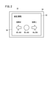
- FIG. 2 is a front view of the operation panel 10 of the embodiment.
- the operation panel 10 includes a display unit 54 and a touch panel 56.
- the display unit 54 has a display screen 52.
- the display screen 52 is, for example, a liquid crystal screen.
- the material of the display screen 52 is not limited to the liquid crystal display.
- the material of the display screen 52 may be organic EL (OEL: Organic Electro-Luminescence).
- OEL Organic Electro-Luminescence
- the user interface (UI: UserInterface) displayed on the display screen 52 of FIG. 2 is an example for explaining the present embodiment as simply as possible.
- the UI of the operation panel 10 is not limited to FIG. 2, and a plurality of buttons may be displayed on the display screen 52 in addition to those shown in FIG.
- the target selection button 58 and the operation start button 60 are displayed on the display screen 52. Each of the target selection button 58 and the operation start button 60 is displayed by a process performed by the display control unit 66. A detailed description of the display control unit 66 will be described later.
- the target selection button 58 is a virtual button for selecting the drive target 50 of the injection molding machine 12.
- the mold button 581 of FIG. 2 is a specific example of the target selection button 58 that selects the mold 14 as the drive target 50.
- the operation start button 60 is a virtual button for starting the operation of the drive target 50.
- the mold opening button 60 1 in FIG. 2 is a specific example of the operation start button 60 for starting the mold opening of the mold 14.
- the mold closing button 60 2 in FIG. 2 is a specific example of the operation start button 60 for starting the mold closing of the mold 14.
- the touch panel 56 is an electronic component for detecting the touch position when the operator touches the display screen 52.
- the touch panel 56 inputs a signal corresponding to the touch position (position signal ST in FIG. 3) to the operation recognition unit 68.
- the details of the operation recognition unit 68 will be described later.
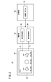
- FIG. 3 is a functional schematic configuration diagram of the operation panel 10.
- the operation panel 10 further includes a calculation unit 62 and a storage unit 64.
- the arithmetic unit 62 includes a processor such as a CPU (Central Processing Unit) or a GPU (Graphics Processing Unit), for example.
- the storage unit 64 includes, for example, a memory such as a RAM (RandomAccessMemory) or a ROM (ReadOnlyMemory).
- the arithmetic unit 62 may include a processor (not shown) of the control device 20 described above. Further, the storage unit 64 may include a memory (not shown) of the control device 20 described above.
- the calculation unit 62 has a display control unit 66 and an operation recognition unit 68.
- the control program 70 is stored in the storage unit 64.
- the control program 70 is a program for realizing the control function of the operation panel 10.
- the calculation unit 62 realizes each of the display control unit 66 and the operation recognition unit 68 by executing the control program 70.
- the display control unit 66 displays each of the target selection button 58 and the operation start button 60 on the display screen 52. If the drive target 50 can move in a plurality of moving directions, the display control unit 66 causes the display screen 52 to display a plurality of operation start buttons 60 corresponding to the plurality of moving directions. As a result, for example, the mold button 58 1 illustrated in FIG. 2, the mold opening button 60 1 , and the mold closing button 60 2 are displayed on the display screen 52.
- the direction from the target selection button 58 toward the operation start button 60 matches the moving direction of the drive target 50. This makes it easier for the operator to understand the moving direction of the drive target 50 that can be instructed by the operation start button 60.
- the display control unit 66 displays the mold opening button 60 1 on the display screen 52 to the left of the mold button 581 .
- the display control unit 66 displays the mold closing button 60 2 on the display screen 52 to the right of the mold button 581 . ..
- the mold opening button 60 1 is a button to be touched when the movable mold 24 is to be moved in the opening direction (when instructing the mold opening). ..
- the shape (icon) of the operation start button 60 is preferably a shape that points in the moving direction.
- the shape pointing in the moving direction is, for example, an arrow shape.
- the mold opening button 60 1 is displayed by an arrow icon pointing in the opening direction.
- the mold closing button 602 is displayed by an arrow icon pointing in the closing direction.
- the position signal ST is input to the operation recognition unit 68 from the touch panel 56.
- the operation recognition unit 68 recognizes where on the display screen 52 is touched based on the position signal ST . For example, when the position signal ST indicates the display area of the mold button 581 , the operation recognition unit 68 recognizes that the mold button 581 has been touched.
- the operation recognition unit 68 recognizes that the start of the operation of the drive target 50 selected by the target selection button 58 is instructed. do. This will be specifically described below.
- FIG. 4 is a flowchart illustrating the flow of the recognition process of the operation start instruction of the drive target 50 by the operation recognition unit 68.
- the operation recognition unit 68 does not recognize that the start of the operation of the drive target 50 is instructed regardless of whether or not the operation start button 60 is touched. For example, in the example of FIG. 2, even if the mold opening button 60 1 is touched while the mold button 581 is not touched, the operation recognition unit 68 does not recognize that the mold opening is instructed. Further, for example, even if the mold closing button 602 is touched while the mold button 581 is not touched, the operation recognition unit 68 does not recognize that the mold closing of the mold 14 is instructed.
- the operation recognition unit 68 operates the drive target 50 selected by the target selection button 58 when the target selection button 58 is touched (S1: YES) and the operation start button 60 is touched (S2: YES). Recognizes that the start of is instructed (S3). For example, in the example of FIG. 2, when the mold button 581 is touched and the mold opening button 60 1 is touched while the touch is maintained, the operation recognition unit 68 recognizes that the start of mold opening is instructed. .. As another example, when, for example, the mold button 581 is touched and the mold closing button 602 is touched while the touch is maintained, the operation recognition unit 68 recognizes that the start of mold closing is instructed.
- the possibility that the mold 14 which is the drive target 50 starts the opening / closing operation without the intention of the operator is reduced. That is, when instructing the opening and closing of the mold 14, the operator touches the mold button 581 and then further touches the mold opening button 60 1 or the mold closing button 602 while maintaining the touch.
- the recognition method requires a plurality of operation steps when the operator instructs the opening / closing of the mold 14. This makes it difficult for the operation recognition unit 68 to recognize the operator's careless contact (touch) with the display screen 52 as an operation start instruction. Further, it is possible to reduce the possibility that the operation recognition unit 68 erroneously recognizes that the mold 14 has been instructed to open / close due to the erroneous detection of the touch panel 56.
- the operation recognition unit 68 recognizes that the start of the operation of the mold 14 has been instructed, the operation recognition unit 68 outputs a signal indicating that the opening / closing instruction of the mold 14 has been given to the control device 20.
- the control device 20 can control the amplifier for driving the motor 44 to open and close the mold 14 as instructed by the operator.
- the operation recognition unit 68 recognizes that the start of the operation of the drive target 50 is instructed and then the touch of both the target selection button 58 and the operation start button 60 is released, the operation of the drive target 50 is stopped. Recognizes that was instructed. This will be specifically described below with reference to FIG.
- the operation recognition unit 68 stops the operation of the drive target 50 while the touch of either the target selection button 58 or the operation start button 60 is maintained after recognizing that the start of the operation of the drive target 50 is instructed. Does not recognize that was instructed. That is, the operation recognition unit 68 does not recognize that the operation of the drive target 50 has been instructed to stop unless the touch of the target selection button 58 is released (S4: NO). Further, even if the touch of the target selection button 58 is released, the operation recognition unit 68 is instructed to stop the operation of the drive target 50 unless the touch of the operation start button 60 is released (S5: NO). Does not recognize. After recognizing that the start of mold opening is instructed, for example, in the example of FIG.
- the operation recognition unit 68 releases the touch of the mold button 581 of the mold button 581 and the mold opening button 601 . It does not recognize that it has been instructed to stop the mold opening. Similarly, after recognizing that the operation recognition unit 68 has been instructed to start the mold opening, even if only the touch of the mold opening button 601 out of the mold button 581 and the mold opening button 60 1 is released, the operation recognition unit 68 may release the touch. It does not recognize that it has been instructed to stop the mold opening.
- the operation recognition unit 68 recognizes that the start of the operation of the drive target 50 is instructed and then the touch of both the target selection button 58 and the operation start button 60 is released (S4: YES, S5: YES). , Recognizes that the operation of the drive target 50 has been instructed to stop (S6). For example, when the operation recognition unit 68 recognizes that the start of mold opening is instructed in the example of FIG. 2, and then the touches of both the mold button 581 and the mold opening button 60 1 are released, the mold opening is stopped. Recognize as instructed. After that, the operation recognition unit 68 outputs a signal indicating that there is an instruction to stop the drive target 50 to the control device 20. Upon receiving this signal, the control device 20 stops the drive target 50.
- the possibility that the mold 14 which is the drive target 50 stops the opening / closing operation without the intention of the operator is reduced. That is, in order to instruct the stop of the opening operation of the mold 14, the operator needs to release both the touch of the mold button 581 and the touch of the mold opening button 601 . As a result, even if the touch of either the mold button 581 or the mold opening button 60 1 is released without the operator's intention (for example, due to a misalignment of a finger), the mold opening operation is not stopped. Further, for example, when the touch panel 56 is not in good condition, the possibility that the operation recognition unit 68 erroneously recognizes that the mold opening stop is instructed is reduced even though the operator continues to touch.
- the drive target 50 is not limited to the mold 14. In the following description, some specific examples of the drive target 50 will be given. Further, an application example of the operation panel 10 when operating the drive target 50 given as an example will be described.
- the mold clamping device 16 described above further includes an ejector device 72.
- the ejector device 72 is a device that drives the movable mold 24 to remove the molded product.
- the ejector device 72 includes an ejector pin 74, an ejector plate 76, a nut 78, and a ball screw 80.
- the ejector pin 74 is a pin (rod-shaped member) for projecting a molded product.
- the ejector plate 76 supports the ejector pin 74.
- the nut 78 is connected to the ejector plate 76. A nut 78 is screwed into the ball screw 80.
- the axial direction of the ball screw 80 is parallel to the protruding direction (retracting direction opposite to the protruding direction) of FIG. 1 in which the ejector pin 74 faces the mold 14.
- the ejector device 72 further includes a driven pulley 82, a motor 84, a drive pulley 86, and a belt 88.
- the driven pulley 82 rotates integrally with the ball screw 80.
- the drive pulley 86 rotates integrally with the rotation shaft (shaft) of the motor 84.
- the belt 88 transmits a rotational force from the drive pulley 86 to the driven pulley 82.
- the ejector device 72 rotates the ball screw 80 by driving the motor 84. Further, the ejector device 72 moves the ejector plate 76 and the ejector pin 74 by the rotation of the ball screw 80.
- the moving direction of the ejector pin 74 can be switched between a protruding direction and a retracting direction by switching the rotation direction of the rotation axis of the motor 84.
- the ejector pin 74 pushes out the molded product from the movable mold 24 by moving in the protruding direction. As a result, the molded product is removed from the movable mold 24. After pushing out the molded product from the movable mold 24, the ejector pin 74 returns to its original position by moving in the retracting direction.
- the motor 84 is driven by an amplifier (not shown). This amplifier is connected to the control device 20. This amplifier is controlled by the control device 20. Therefore, the motor 84 is substantially controlled by the control device 20.
- FIG. 5 is a diagram illustrating a display screen 52 of the operation panel 10 applied to the operation of the ejector device 72.
- the ejector device 72 (ejector pin 74) that performs each of the ejection operation and the backward operation as described above is one of the specific examples of the drive target 50.
- the operation panel 10 may be applied to operate the ejector device 72. Specifically, for example, the operation panel 10 may be applied to indicate each of the ejection and the retreat of the ejector pin 74.
- the UI displayed on the display screen 52 is, for example, as shown in FIG. On the display screen 52 of FIG . 5, an ejector button 582, a protrusion button 603 , and a retract button 604 are displayed.
- the ejector button 582 is a target selection button 58 for selecting the ejector device 72 (ejector pin 74) as the drive target 50.
- the protrusion button 60 3 is an operation start button 60 for instructing the start of the protrusion operation of the ejector pin 74.
- the retreat button 604 is an operation start button 60 for instructing the start of the retreat operation of the ejector pin 74. It is preferable that the retract button 604 is displayed on the display screen 52 on the side in the opening direction from the ejector button 582. Further, it is preferable that the protrusion button 603 is displayed on the display screen 52 in the area in the closing direction from the ejector button 582 .
- the operator touches the protrusion button 603 while touching the ejector button 582.
- the ejection of the ejector pin 74 is instructed to the control device 20.
- the operator touches the retract button 604 while touching the ejector button 582 .
- the control device 20 is instructed to retract the ejector pin 74.
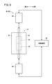
- FIG. 6 is a schematic configuration diagram of the core driving device 90.
- the mold clamping device 16 further includes a core driving device 90 as shown in FIG.
- the core drive device 90 includes a core 92 and a hydraulic cylinder 94.
- the hydraulic cylinder 94 is an actuator that moves the core 92 inside and outside the cavity of the mold 14. In the example of FIG. 6, the hydraulic cylinder 94 moves the core 92 along the vertical direction of the paper surface.
- the hydraulic cylinder 94 is controlled by the control device 20.
- FIG. 7 is a diagram illustrating a display screen 52 of the operation panel 10 applied to the operation of the core 92.
- the core driving device 90 (core 92) described above is one of the specific examples of the driving target 50.
- the operation panel 10 may be applied to operate the core drive device 90. Specifically, for example, the operation panel 10 may be applied to operate the movement of the core 92 in and out of the cavity.
- the UI displayed on the display screen 52 is, for example, as shown in FIG.
- a core button 583 , a core set button 605, and a core pull button 606 are displayed on the display screen 52 of FIG. 7 .
- the core button 583 3 is a target selection button 58 for selecting the core drive device 90 (core 92) as the drive target 50.
- the core set button 605 is an operation start button 60 for instructing the start of movement (core set) of the core 92 into the cavity.
- the core pull button 606 is an operation start button 60 that instructs the start of movement (core pull) of the core 92 to the outside of the cavity.
- the operator touches the core set button 605 while touching the core button 583.
- the control device 20 is instructed to start the core set.
- the operator touches the core button 583 and touches the core pull button 606 while maintaining the touch.
- the control device 20 is instructed to start the core pull.
- the actuator for moving the core 92 is not limited to the hydraulic cylinder 94.
- the actuator for moving the core 92 may be a motor.
- FIG. 8 is a schematic configuration diagram of the mold clamp device 96.
- the mold clamping device 16 further includes the mold clamping device 96 shown in FIG.
- the mold clamp device 96 is a hydraulic clamp device in this example. That is, the mold clamp device 96 includes a clamper 98 and a hydraulic cylinder 100.
- the clamper 98 includes a clamper 98 attached to the fixed platen 26 and a clamper 98 attached to the movable platen 28.
- the hydraulic cylinder 100 drives the clamper 98.
- the clamper 98 attached to the fixed platen 26 engages (clamps) the attachment plate 102 to which the fixing mold 22 is attached. As a result, the fixed mold 22 is fixed to the fixed platen 26.
- the clamper 98 attached to the movable platen 28 engages (clamps) the attachment plate 104 to which the movable mold 24 is attached. As a result, the movable mold 24 is fixed to the movable platen 28.
- the hydraulic cylinder 100 switches between engaging and disengaging (unclamping) the clamper 98.
- FIG. 9 is a diagram illustrating a display screen 52 of the operation panel 10 applied to the operation of the mold clamp device 96.
- the mold clamp device 96 (clamper 98) is one of specific examples of the drive target 50.
- the operation panel 10 may be applied to operate the mold clamping device 96. Specifically, for example, the operation panel 10 may be applied to instruct switching between clamping and unclamping of the mold 14 by the mold clamping device 96.
- the UI displayed on the display screen 52 is, for example, as shown in FIG.
- a clamper button 584, a clamp button 607 , and an unclamp button 608 are displayed.
- the clamper button 584 is an object selection button 58 for selecting the mold clamping device 96 ( clamper 98) as the drive target 50.
- the clamp button 607 is an operation start button 60 for instructing the clamp of the mold 14 .
- the unclamp button 608 is an operation start button 60 for instructing the unclamping of the mold 14 .
- the operator touches the clamp button 607 while touching the clamper button 584.
- the clamp of the mold 14 is instructed to the control device 20.
- the operator touches the unclamp button 608 while touching the clamper button 584 .
- the unclamping of the mold 14 is instructed to the control device 20.
- the injection molding machine 12 further includes an injection device 106.
- the injection device 106 is a device that melts the material (resin material) of the molded product and injects it into the mold 14.
- FIG. 10 is a schematic configuration diagram of the injection device 106.
- the front-rear direction of the injection device 106 shown in FIG. 10 is parallel to the opening / closing direction of the mold 14.
- the mold 14 and the mold clamping device 16 are installed at positions in the front direction of the injection device 106.
- the injection device 106 includes a cylinder 108, a nozzle 110, and a screw 112.
- the cylinder 108 is a tubular member.
- the nozzle 110 is attached to the front end of the cylinder 108.
- the screw 112 is installed in the cylinder 108.
- the axial direction of the screw 112 is parallel to the front-rear direction.
- the injection device 106 further includes a first drive device 114 and a second drive device 116 that rotates the screw 112 in the cylinder 108.
- the first drive device 114 is a device for moving the screw 112 in the cylinder 108.
- the first drive device 114 includes a motor 118, a drive pulley 120, a driven pulley 122, and a belt 124.
- the drive pulley 120 rotates integrally with the rotation shaft (shaft) of the motor 118.
- the driven pulley 122 rotates integrally with the screw 112.
- the belt 124 transmits a rotational force from the drive pulley 120 to the driven pulley 122.
- the first drive device 114 further includes a ball screw 126 and a nut 128.
- the ball screw 126 extends in the axial direction of the screw 112.
- the nut 128 is screwed into the ball screw 126.
- the first drive device 114 drives the motor 118 to move the screw 112 in the front-rear direction.
- the motor 118 is driven by an amplifier (not shown). This amplifier is connected to the control device 20. This amplifier is controlled by the control device 20. Therefore, the motor 118 is substantially controlled by the control device 20.
- the second drive device 116 is a device that rotates the screw 112 in the cylinder 108.
- the second drive device 116 includes a motor 130, a drive pulley 132, a driven pulley 134, and a belt 136.
- the drive pulley 132 rotates integrally with the rotation shaft (shaft) of the motor 130.
- the driven pulley 134 rotates integrally with the screw 112.
- the belt 136 transmits a rotational force from the drive pulley 132 to the driven pulley 134.
- the second drive device 116 rotates the screw 112 in response to the drive of the motor 130.
- the motor 130 is driven by an amplifier (not shown). This amplifier is connected to the control device 20. This amplifier is controlled by the control device 20. Therefore, the motor 130 is substantially controlled by the control device 20.
- the injection device 106 further includes a hopper 138 and a heater 140.
- the hopper 138 stores the resin material.
- the resin material is charged into the cylinder 108 from the hopper 138.
- the heater 140 heats the resin material charged into the cylinder 108.
- the resin material stored in the hopper 138 is, for example, a granular solid substance (pellet).
- the pellet changes from a solid to a plastic molten resin by the heat of the heater 140 and the shearing heat generated by the rotation of the screw 112.
- the screw 112 rotates along a predetermined rotation direction.
- the molten resin is pressure-fed in the cylinder 108 in the forward direction (toward the nozzle 110).
- the screw 112 receives a reaction force from the molten resin and recedes.
- the injection device 106 advances the screw 112 after pumping a predetermined amount of the molten resin toward the nozzle 110.
- the molten resin in the cylinder 108 is ejected out of the cylinder 108 through the nozzle 110.
- the injection device 106 (screw 112) is one of the specific examples of the drive target 50.
- the operation panel 10 may be applied to operate the above injection device 106. Specifically, for example, the operation panel 10 may be applied to instruct the forward movement of the screw 112 at the time of injection of the molten resin.
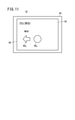
- FIG. 11 is a diagram illustrating a display screen 52 of the operation panel 10 applied to the operation of forward movement of the screw 112.
- the UI displayed on the display screen 52 is, for example, as shown in FIG.
- the first screw button 585 and the ejection button 609 are displayed.
- the first screw button 585 is a target selection button 58 for selecting the screw 112 as the drive target 50 .
- the ejection button 609 is an operation start button 60 for instructing the start of forward movement of the screw 112 at the time of ejection. As described above, it is preferable that the ejection button 609 is displayed on the display screen 52 in the front direction (leftward on the paper in FIG. 11) side of the first screw button 585.
- the operator touches the ejection button 609 while touching the first screw button 585.
- the control device 20 is instructed to start the forward movement (injection) of the screw 112.
- the operation panel 10 may be applied to instruct the rotational operation of the screw 112 at the time of pumping the molten resin described in the application example 4.
- FIG. 12 is a diagram illustrating a display screen 52 of the operation panel 10 applied to the operation of rotating the screw 112.
- the UI displayed on the display screen 52 is, for example, as shown in FIG.
- the second screw button 586 and the screw rotation button 60 10 are displayed on the display screen 52 of FIG.
- the second screw button 586 is a target selection button 58 for selecting the screw 112 as the drive target 50.
- the screw rotation button 60 10 is an operation start button 60 for instructing the start of pumping of the molten resin (rotation of the screw 112 along a predetermined rotation direction).
- the screw rotation button 60 10 shown in FIG. 12 has an arrow shape having a substantially arc shape.
- the shape (icon) of the operation start button 60 for instructing the rotation of the drive target 50 is preferably a shape indicating that the instructed operation is rotation.
- the operation content instructed to the control device 20 by operating the operation start button 60 becomes easy for the operator to understand.
- the operator touches the screw rotation button 60 10 while touching the second screw button 586.
- the control device 20 is instructed to start pumping the molten resin (rotation of the screw 112 along a predetermined rotation direction).
- FIG. 13 is a schematic diagram illustrating the mold rotating device 142.
- FIG. 13 is a viewpoint along the opening / closing direction of the mold 14.
- the injection molding machine 12 may further include the mold rotating device 142 shown in FIG.
- the mold rotating device 142 is a device for rotating the mold 14.
- the mold rotating device 142 includes, for example, a rotating disk 144 and a motor 146, as shown in FIG.
- the turntable 144 is installed on the fixed platen 26.
- the turntable 144 rotatably supports the fixed mold 22.
- the motor 146 applies a rotational force to the turntable 144.
- a plurality of members (pulleys, gears) for transmitting the rotational force of the motor 146 to the rotary disk 144 are actually between the rotary disk 144 and the motor 146. May be installed.
- the turntable 144 rotates according to the drive of the motor 146.
- the motor 146 is, for example, a servo motor.
- the motor 146 is controlled by the control device 20.
- the turntable 144 may be installed on the movable platen 28. In that case, the turntable 144 rotatably supports the movable mold 24 instead of the fixed mold 22. As a result, the movable mold 24 rotates together with the turntable 144.
- FIG. 14 is a diagram illustrating a display screen 52 of the operation panel 10 applied to the rotation operation of the mold 14.
- the mold 14 is a drive target 50 that performs a rotating operation.
- the operation panel 10 may be applied to operate the rotation of the mold 14 (rotary disk 144).
- the UI displayed on the display screen 52 is, for example, as shown in FIG.
- the mold button 587 is displayed on the display screen 52 of FIG.
- the mold button 587 is a target selection button 58 for selecting the mold 14 (rotary disk 144) as the rotating drive target 50.
- a forward rotation button 60 11 and a reverse rotation button 60 12 are displayed.
- the forward rotation button 60 11 is an operation start button 60 for rotating the mold 14 along the positive rotation direction.
- the reverse rotation button 60 12 is an operation start button 60 for rotating the mold 14 along the reverse rotation direction (rotation direction opposite to the positive rotation direction).
- the positive rotation direction is the clockwise direction from the viewpoint of FIG. 13 (the reverse rotation direction is the counterclockwise direction).
- a forward rotation button 60 11 for instructing clockwise rotation of the mold 14 is displayed on the right side of the mold button 587 in the display screen 52.
- the rotation direction (clockwise direction) of the mold 14 instructed by the control device 20 by operating the forward rotation button 60 11 becomes intuitively easy for the operator to understand.
- the reverse rotation button 60 12 instructing the counterclockwise rotation of the mold 14 is displayed on the left side of the mold button 587 in the display screen 52.
- the rotation direction (counterclockwise direction) of the mold 14 instructed by the control device 20 by operating the reverse rotation button 60 12 becomes intuitively easy for the operator to understand.
- the operator touches the forward rotation button 60 11 while touching the mold button 587 .
- the control device 20 is instructed to start the rotation (clockwise rotation) of the mold 14.
- the operator touches the reverse rotation button 60 12 while touching the mold button 587 .
- the control device 20 is instructed to start the rotation (counterclockwise) of the mold 14.
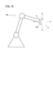
- FIG. 15 is a schematic configuration diagram of a robot 148 provided in the injection molding machine 12.
- the injection molding machine 12 may further include a robot 148 as shown in FIG.
- the robot 148 includes an arm 150.
- the arm 150 is driven by a plurality of motors (not shown).
- the plurality of arrows around the arm 150 indicate the driving direction of the arm 150.
- the driving direction of the arm 150 is not limited to the example of FIG.
- the robot 148 is arranged, for example, in the vicinity (side) of the mold 14 at a distance from the mold 14.
- the arm 150 of the robot 148 holds, for example, an insert product. Further, the arm 150 inserts, for example, an insert product into the cavity.
- the arm 150 of the robot 148 takes out the molded product from the mold 14 and places the molded product in the molded product storage place (conveyor).
- FIG. 16 is a diagram illustrating a display screen 52 of the operation panel 10 applied to the operation of the robot 148.
- the operation panel 10 of the present embodiment may be applied to operate the above robot 148. Specifically, for example, the operation panel 10 may be applied to operate the movement destination of the arm 150.
- the UI displayed on the display screen 52 is, for example, as shown in FIG.
- a robot button 588 and a plurality of arm movement buttons 60 13 are displayed.
- the robot button 588 is a target selection button 58 for selecting the robot 148 ( arm 150) as the drive target 50.
- Each of the plurality of arm movement buttons 60 13 is an operation start button 60 for instructing the movement of the arm 150 along the corresponding drive direction.
- Each of the plurality of arm movement buttons 60 13 corresponds to different driving directions from each other.
- the arm movement button 60 13 displayed on the right side of the robot button 588 on the display screen 52 is an operation start button 60 for instructing the movement of the arm 150 along the right direction of the paper in FIG.
- the arm movement button 60 13 displayed below the robot button 588 on the display screen 52 is an operation start button 60 for instructing the movement of the arm 150 along the downward direction of the paper in FIG.
- the operator touches one of the plurality of arm movement buttons 60 13 while touching the robot button 588 .
- the control device 20 is instructed to move the arm 150.
- Mode 1 When the operation recognition unit 68 of the embodiment recognizes that the start of the operation of the drive target 50 is instructed and then the touch of both the target selection button 58 and the operation start button 60 is released, the drive target 50 Recognized that the operation was instructed to stop.
- the operation recognition unit 68 is not limited to this. That is, when the operation recognition unit 68 recognizes that the start of the operation of the drive target 50 is instructed and then the touch of either the target selection button 58 or the operation start button 60 is released, the drive target 50 It may be recognized that the stop of operation is instructed. In this case, when the operator wants to stop the operation of the drive target 50, the operator releases one of the touch to the target selection button 58 and the touch to the operation start button 60. As a result, the operation of the drive target 50 is easily and quickly stopped.
- Modification 2 The touch operation required for the operation recognition unit 68 to recognize that the drive target 50 has been selected may include a so-called slide operation. As a result, the risk of malfunction of the drive target 50 is further reduced.
- slide operation As a result, such an example of this modification will be described with reference to the drawings.
- FIG. 17 is a flowchart illustrating the flow of recognition processing of the operation start instruction and stop instruction of the drive target 50 by the operation recognition unit 68 of the modification 2.
- the operation recognition unit 68 of the present modification slides the touch position as it is and reaches the operation start button 60 (S12: YES). ), Recognizing that the start of operation has been instructed (S13). If the touch is released while sliding from the target selection button 58 to the operation start button 60 (S12: NO), the operation recognition unit 68 does not recognize that the operation of the drive target 50 has been instructed to start. Further, when the operation recognition unit 68 of this modification recognizes that the operation start of the drive target 50 is instructed and then the touch of the operation start button 60 is released (S15: YES), the operation of the drive target 50 is stopped. Is instructed (S16).
- FIG. 18A is a first diagram for explaining a procedure for selecting a drive target 50 in the second modification.
- FIG. 18B is a second diagram for explaining the procedure for selecting the drive target 50 in the second modification.
- FIG. 17 The operation flow illustrated in FIG. 17 will be described from the operator's point of view. That is, when instructing the start of operation of the drive target 50 in this modification, the operator first touches the target selection button 58 as shown in FIG. 18A. As a result, the drive target 50 is selected. Next, as shown in FIG. 18B, the operator slides the touch position to the operation start button 60 while touching the target selection button 58. As a result, the selected drive target 50 starts operation. When the operator wants to stop the operation of the drive target 50, the operator releases the touch of the operation start button 60 from the state shown in FIG. 18B. As a result, the operation of the drive target 50 is quickly stopped.
- the drive target 50 does not start the operation unless the touch position is slid from the target selection button 58 to the operation start button 60. Therefore, for example, even if the operator carelessly touches the target selection button 58 or the operation start button 60, the drive target 50 does not start the operation by itself. That is, according to this modification, the possibility that the drive target 50 stops without the intention of the operator is further reduced as compared with the embodiment.
- each of the selection of the drive target 50, the start instruction of the operation of the selected drive target 50, and the stop instruction of the operation is completed by the operation with one finger of the operator. Therefore, the operator can give an instruction to the drive target 50 with a simple operation.
- the operation recognition unit 68 selects the drive target 50 when the touch position is slid (swipe) by a predetermined distance in a predetermined slide direction while the target selection button 58 is touched. It may be recognized that it has been done. In this case, the operation recognition unit 68 recognizes that the start of the operation of the drive target 50 is instructed when the operation start button 60 is touched while the touch of the swipe destination is maintained.
- the display control unit 66 may display the operation start button 60, which instructs the drive target 50 (control device 20) to move faster, at a position farther from the target selection button 58. As a result, the operator can grasp the approximate moving speed of the drive target 50 instructed by the operation start button 60 from the above distance.
- the display control unit 66 displays on the display screen 52 larger (wider or longer) as the operation start button 60 instructs the drive target 50 (control device 20) to move faster. As a result, the moving speed of the drive target 50 instructed by the operation start button 60 becomes easy for the operator to understand.
- a plurality of operation start buttons 60 may be provided corresponding to a plurality of moving speeds of the drive target 50. This allows the operator to select the moving speed of the drive target 50.
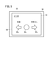
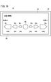
- FIG. 19 is a diagram illustrating the display screen 52 of the operation panel 10 of the modified example 5.
- three mold opening buttons 60 1 and three mold closing buttons 60 2 are displayed.
- the three mold opening buttons 60 1 specify moving speeds of 20%, 50%, and 100% of the maximum allowable speed of the movable mold 24 at the time of mold opening, respectively. In this case, the operator selects the moving speed of the movable mold 24 from 20%, 50%, and 100% of the maximum allowable speed when instructing the mold opening.
- the three mold closing buttons 60 2 specify moving speeds of 20%, 50%, and 100% of the maximum allowable speed of the movable mold 24 when the mold is closed, respectively. Therefore, the operator can select the moving speed of the movable mold 24 from 20%, 50%, and 100% of the maximum allowable speed when instructing the mold to be closed.
- This modification is more preferably combined with the modification 4. That is, in the example of FIG. 19, the mold opening button 601 instructing the drive target 50 (control device 20) to move faster is displayed at a position farther from the mold button 581 . Similarly, the closer the mold closing button 602 is instructing the drive target 50 (control device 20 ) to move faster, the farther it is displayed from the mold button 581 . As a result, for example, the operator can intuitively determine which of the three mold opening buttons 60 1 is the button for instructing the drive target 50 (control device 20) to perform the fastest mold opening. It will be easier to understand.
- this modification can be applied when operating the drive target 50 that can operate at a plurality of moving speeds. Therefore, this modification is not limited to the case of operating the opening / closing operation of the mold 14. Further, in this modification, the moving speeds of the mold 14 are classified into three cases of 20%, 50%, and 100% of the allowable maximum speeds for illustration purposes. However, the case of the moving speed of the mold 14 (movable mold 24) is not limited to this.
- the display control unit 66 may display the operation start button 60, which instructs the drive target 50 (control device 20) to rotate faster, at a position farther from the target selection button 58. As a result, the operator can grasp the approximate rotation speed of the drive target 50 instructed by the operation start button 60 from the above distance.
- the display control unit 66 displays on the display screen 52 larger (wider or longer) as the operation start button 60 instructs the drive target 50 (control device 20) to rotate faster. As a result, the rotation speed of the drive target 50 instructed by the operation start button 60 becomes easy for the operator to understand.
- a plurality of operation start buttons 60 may be displayed corresponding to a plurality of rotation speeds of the drive target 50. Thereby, the operator can select the rotation speed of the drive target 50 from a plurality of rotation speeds.
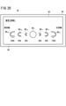
- FIG. 20 is a diagram illustrating the display screen 52 of the operation panel 10 of the modified example 7.
- a mold button 587 On the display screen 52 of FIG. 20, a mold button 587, three forward rotation buttons 60 11 and three reverse rotation buttons 60 12 are displayed.
- the number of each of the forward rotation button 60 11 and the reverse rotation button 60 12 shown in FIG. 20 is not limited to three.
- Each of the three forward rotation buttons 60 11 indicates the rotation of the mold 14 at different rotation speeds from each other.
- each of the three reverse rotation buttons 60 12 indicates the rotation of the mold 14 at different rotation speeds from each other. In this case, the operator can select the rotation speed of the mold 14 from three different rotation speeds in the case of instructing the forward rotation of the mold 14 and the case of instructing the reverse rotation of the mold 14. ..
- This modification is more preferably combined with the modification 6. That is, in the example of FIG. 20, the forward rotation button 60 11 instructing the drive target 50 (control device 20) to rotate faster is displayed at a position farther from the mold button 587 . Similarly, in the example of FIG. 20, the reverse rotation button 60 12 instructing the drive target 50 (control device 20) to rotate faster is displayed at a position farther from the mold button 587 . As a result, for example, the operator can intuitively understand which of the three forward rotation buttons 60 11 is the button for instructing the drive target 50 (control device 20 ) to rotate the fastest. It will be easier.
- this modification can be applied when operating the drive target 50 that can operate at a plurality of rotation speeds. Therefore, this modification is not limited to the case where the rotation operation of the mold 14 is operated. Further, in this modification, the rotation speed of the mold 14 is classified into three cases of 20%, 50%, and 100% of the allowable maximum speed for illustration. However, the case of the rotation speed of the mold 14 is not limited to this.
- the touch panel (56) for detecting the touch position on the top and the target selection button (58) are touched and the operation start button (60) is touched while the touch is maintained, the target selection button (60) is touched.
- This provides an operation panel (10) of the injection molding machine (12) that reduces the risk of malfunction of the drive target (50).
- the operation recognition unit (68) when the operation start button (60) is touched while the touch position is slid after the target selection button (58) is touched and the touch is continued. May recognize that the start of the operation of the drive target (50) selected by the target selection button (58) has been instructed. As a result, for example, when the operator carelessly touches the target selection button (58) or the operation start button (60), it is possible to reduce the possibility that the drive target (50) unintentionally starts the operation. It becomes.
- the operation recognition unit (68) has a drive target (58) selected by the target selection button (58) when the touch position slid from the target selection button (58) reaches the operation start button (60). It may be recognized that the start of the operation of 50) is instructed. As a result, for example, when the operator carelessly touches the target selection button (58) or the operation start button (60), it is possible to reduce the possibility that the drive target (50) unintentionally starts the operation. It becomes. Further, the operator can complete the operation from the selection of the drive target (50) to the start of the operation on the selected drive target (50) with a simple operation with one finger.
- the operation recognition unit (68) may release the touch. It may be recognized that the stop of the operation of the drive target (50) is instructed. As a result, the operator can select the drive target (50), instruct the start of the operation of the selected drive target (50), and instruct the stop of the operation of the drive target (50) with a simple operation with one finger. Can be made to.
- the touch of either the target selection button (58) or the operation start button (60) is released. If so, it may be recognized that the operation of the drive target (50) has been instructed to stop. As a result, the operator can easily and quickly stop the operation of the drive target (50).
- the operation recognition unit (68) recognizes that the start of the operation of the drive target (50) is instructed, and then the touch of both the target selection button (58) and the operation start button (60) is released. May recognize that the stop of the operation of the drive target (50) has been instructed. This reduces the risk that the drive target (50) will stop operating without the operator's intention. Further, for example, when the touch panel (56) is not in good condition, the operation recognition unit (68) erroneously recognizes that the operation stop is instructed even though the operator continues to touch. Can be done.
- the drive target (50) may be movable, and the operation start button (60) may be a button for starting the movement of the drive target (50). Thereby, the operator can instruct the moving drive target (50) to start the movement by using the operation panel (10).
- the display unit (54) has the target selection button so that the direction of the display position of the operation start button (60) with respect to the display position of the target selection button (58) is the moving direction of the drive target (50). (58) and the operation start button (60) may be displayed. As a result, it is possible to provide a UI in which the moving direction of the drive target (50) that can be instructed is intuitively easy for the operator to understand.
- the drive target (50) can be moved in a plurality of moving directions, and a plurality of the operation start buttons (60) are provided corresponding to the plurality of moving directions of the drive target (50), and the display unit (60) is provided.
- the drive target (50) moves in the direction of the display positions of the plurality of operation start buttons (60) with respect to the display position of the target selection button (58) by the operation of the operation start button (60).
- the target selection button (58) and the plurality of operation start buttons (60) may be displayed so as to be oriented in the direction.
- a plurality of the operation start buttons (60) are provided corresponding to a plurality of moving speeds of the driving target (50) in the moving direction, and the display unit (54) is a display position of the target selection button (58).
- the target selection button (58) increases the distance of the display position of the operation start button (60) with respect to the movement speed at which the drive target (50) moves by the operation of the operation start button (60).
- the plurality of operation start buttons (60) may be displayed. This makes it possible to provide a UI in which the movement speed of the drive target (50) that can be instructed in each movement direction is intuitively easy for the operator to understand.
- a plurality of the operation start buttons (60) are provided corresponding to a plurality of moving speeds of the drive target (50), and the display unit (54) starts the operation with respect to the display position of the target selection button (58).
- the target selection button (58) and the operation start so that the distance of the display position of the button (60) becomes longer as the moving speed at which the drive target (50) moves by the operation of the operation start button (60) becomes longer.
- the button (60) may be displayed.
- the drive target (50) is rotatable, and the operation start button (60) may be a button for starting the rotation of the drive target (50). Thereby, the operator can instruct the rotating drive target (50) to start the rotation by using the operation panel (10).
- At least two operation start buttons (60) are provided corresponding to a positive rotation direction of the drive target (50) and a rotation direction opposite to the positive rotation direction, and the display unit (54) is provided.
- the drive target is rotated in the direction opposite to the direction of the display position of the operation start button (60) with respect to the display position of the target selection button (58), which rotates the drive target (50) in the positive rotation direction.
- the target selection button (58) and at least two so that the direction of the display position of the operation start button (60) for rotating (50) with respect to the display position of the target selection button (58) is opposite to each other.
- the operation start button (60) may be displayed. This makes it possible to provide a UI in which the rotation direction of the drive target (50) that can be instructed is intuitively easy for the operator to understand.
- a plurality of the operation start buttons (60) are provided corresponding to a plurality of rotation speeds in the rotation direction of the drive target (50), and the display unit (54) is provided with respect to the display position of the target selection button (58).
- the target selection button (58) and the target selection button (58) so that the distance between the display positions of the operation start button (60) becomes longer as the rotation speed at which the drive target (50) rotates by the operation of the operation start button (60) becomes faster.
- the operation start button (60) may be displayed. This makes it possible to provide a UI in which the rotation speed of the drive target (50) that can be instructed in each rotation direction is intuitively easy for the operator to understand.
- a plurality of the operation start buttons (60) are provided corresponding to a plurality of rotation speeds of the drive target (50), and the display unit (54) starts the operation with respect to the display position of the target selection button (58).
- the target selection button (58) and the operation start so that the distance of the display position of the button (60) becomes longer as the rotation speed at which the drive target (50) rotates by the operation of the operation start button (60) becomes longer.
- the button (60) may be displayed. This makes it possible to provide a UI in which the rotation speed of the drive target (50) that can be instructed is intuitively easy for the operator to understand.
Landscapes
- Engineering & Computer Science (AREA)
- General Engineering & Computer Science (AREA)
- Theoretical Computer Science (AREA)
- Human Computer Interaction (AREA)
- Physics & Mathematics (AREA)
- General Physics & Mathematics (AREA)
- Manufacturing & Machinery (AREA)
- Mechanical Engineering (AREA)
- Injection Moulding Of Plastics Or The Like (AREA)
- User Interface Of Digital Computer (AREA)
- Moulds For Moulding Plastics Or The Like (AREA)
Abstract
射出成形機(12)の操作パネル(10)であって、対象選択ボタン(58)と動作開始ボタン(60)とを表示する表示部(54)と、オペレータの表示画面(52)上におけるタッチ位置を検出するタッチパネル(56)と、対象選択ボタン(58)がタッチされたまま、動作開始ボタン(60)がタッチされた場合は、駆動対象(50)の動作の開始が指示されたと認識する操作認識部(68)と、を備える。
Description
本発明は、射出成形機の操作パネルに関する。
射出成形機の分野において、タッチ操作式の操作パネルが知られている(例えば、特公平07-004845号公報)。
タッチ操作式の操作パネルは、オペレータが意図しない操作を認識することがある。その原因としては、例えばオペレータによる誤操作、およびタッチパネルの誤動作がある。この場合、射出成形機の駆動対象がオペレータの意図しない動作を行う。
本発明は、上述した課題を解決することを目的とする。
本発明の態様は、射出成形機の操作パネルであって、表示画面を有し、射出成形機の駆動対象を選択する対象選択ボタン、および前記駆動対象の動作を開始させる動作開始ボタンを前記表示画面に表示する表示部と、前記表示画面に設けられ、オペレータの前記表示画面上におけるタッチ位置を検出するタッチパネルと、前記対象選択ボタンがタッチされ、そのタッチが維持された状態で、前記動作開始ボタンがタッチされた場合は、前記対象選択ボタンによって選択された駆動対象の動作の開始が指示されたと認識する操作認識部と、を備える。
本発明によれば、駆動対象の誤動作のおそれが低減される。
[実施の形態]
図1は、実施の形態の操作パネル10が適用される射出成形機12の構成図である。図1に矢印で示す開方向と閉方向とは互いに相反する方向である。本実施の形態では、開方向と閉方向とはいずれも水平に平行である。
図1は、実施の形態の操作パネル10が適用される射出成形機12の構成図である。図1に矢印で示す開方向と閉方向とは互いに相反する方向である。本実施の形態では、開方向と閉方向とはいずれも水平に平行である。
まず、図1を参照して、本実施の形態の操作パネル10が適用される射出成形機12について説明する。図1に示すように、射出成形機12は、金型14と、型締装置16と、機台18と、制御装置20とを備える。
金型14は、固定金型22と、可動金型24とを有する。固定金型22は、開閉方向に関して移動しないように、機台18上に設置される。可動金型24は、開閉方向に沿って移動可能に、機台18上に設置される。
型締装置16は、可動金型24を開閉方向に沿って移動させる装置である。型締装置16は、機台18上に設置される。型締装置16は、固定プラテン26と、可動プラテン28とを備える。固定プラテン26は、取付板102を介して固定金型22を支持する。可動プラテン28は、取付板104を介して可動金型24を支持する。また、型締装置16は、金型開閉機構30と、リアプラテン32と、複数のタイバー33とをさらに備える。金型開閉機構30は、可動プラテン28を開閉方向に沿って移動させる。可動金型24は、可動プラテン28と一緒に移動する。リアプラテン32は、可動プラテン28から開方向に離れた位置に設置される。複数のタイバー33は、固定プラテン26とリアプラテン32とを連結する。
金型開閉機構30は、本実施の形態ではトグル式の開閉機構である。すなわち、金型開閉機構30は、クロスヘッド36と、ナット38と、ボールネジ40とを備える。クロスヘッド36は、トグルリンク34を介して可動プラテン28に接続される。また、ナット38は、クロスヘッド36に連結される。ボールネジ40には、ナット38が螺合する。ボールネジ40の軸線方向は開閉方向である。ボールネジ40はリアプラテン32によって回転可能に支持される。また、金型開閉機構30は、従動プーリ42と、モータ44と、駆動プーリ46と、ベルト48とをさらに備える。従動プーリ42は、ボールネジ40と一体的に回転する。駆動プーリ46は、モータ44の回転軸(シャフト)と一体的に回転する。ベルト48は、駆動プーリ46から従動プーリ42へと回転力を伝達する。なお、モータ44は、図示しないアンプによって駆動される。このアンプは制御装置20に接続されている。このアンプは、制御装置20によって制御される。したがって、モータ44は、制御装置20によって、実質的に制御される。
モータ44は、ボールネジ40を回転させる。ボールネジ40が回転すると、クロスヘッド36およびナット38が開閉方向に沿って移動する。クロスヘッド36が開閉方向に沿って移動すると、可動プラテン28および可動金型24が、開閉方向に沿って一体的に移動する。可動金型24は、閉方向に移動することで、固定金型22と接する(型閉じ)。型閉じを行うと、金型14にキャビティが形成される。また、可動金型24は、開方向に移動することで、固定金型22から離れる(型開き)。
制御装置20は、射出成形機12全体の制御を担う電子装置(コンピュータ)である。制御装置20は、図示しないプロセッサおよびメモリを備える。制御装置20のメモリには、所定のプログラムが格納される。制御装置20のプロセッサは、所定のプログラムを実行することで、射出成形機12を制御する。
制御装置20には操作パネル10が設けられる。オペレータは、制御装置20に指示(駆動対象50の動作に関する指示)を出すために、操作パネル10を使用する。
駆動対象50は、射出成形機12において所定の動作を行う要素である。例えば前述した金型14(より正確には、金型14の可動金型24)は、射出成形機12において型開きおよび型閉じを行う。したがって、金型14は駆動対象50の具体例の1つである。この場合、操作パネル10は、型開きの開始、および型閉じの開始を、オペレータが制御装置20に指示するために使用される。以下の説明では、金型14を駆動対象50として、型開き(開始/停止)、および型閉じ(開始/停止)の各々をオペレータが指示するための操作パネル10の一例を説明する。
図2は、実施の形態の操作パネル10の正面図である。
図2に示すように、操作パネル10は表示部54と、タッチパネル56とを備える。表示部54は表示画面52を有する。表示画面52は例えば液晶画面である。ただし、表示画面52の材料は液晶に限定されない。例えば表示画面52の材料は、有機EL(OEL:Organic Electro-Luminescence)であってもよい。なお、図2の表示画面52に表示されているユーザインターフェース(UI:User Interface)は、本実施の形態をできるだけ簡単に説明するための例示である。操作パネル10のUIは図2に限定されず、表示画面52には図2に示す以外にも複数のボタンが表示されてもよい。
表示画面52には、対象選択ボタン58と、動作開始ボタン60とが表示される。対象選択ボタン58と、動作開始ボタン60との各々は、いずれも表示制御部66が行う処理によって表示される。表示制御部66の詳細な説明は後述する。対象選択ボタン58は、射出成形機12の駆動対象50を選択する仮想的なボタンである。図2の金型ボタン581は、駆動対象50として金型14を選択する対象選択ボタン58の具体例である。動作開始ボタン60は駆動対象50の動作を開始させる仮想的なボタンである。図2の型開きボタン601は、金型14の型開きを開始させる動作開始ボタン60の具体例である。図2の型閉じボタン602は、金型14の型閉じを開始させる動作開始ボタン60の具体例である。
タッチパネル56は、オペレータが表示画面52にタッチしたときに、そのタッチ位置を検出するための電子部品である。タッチパネル56は、オペレータが表示画面52にタッチしたときに、そのタッチ位置に応じた信号(図3の位置信号ST)を操作認識部68に入力する。操作認識部68の詳細は後述する。
図3は、操作パネル10の機能的な概略構成図である。
図3に示すように、操作パネル10は、演算部62と記憶部64とをさらに備える。演算部62は、例えばCPU(Central Processing Unit)やGPU(Graphics Processing Unit)等のプロセッサを含む。記憶部64は、例えばRAM(Random Access Memory)やROM(Read Only Memory)等のメモリを含む。なお、演算部62は、前述した制御装置20の不図示のプロセッサを含んでもよい。また、記憶部64は、前述した制御装置20の不図示のメモリを含んでもよい。
演算部62は、表示制御部66と、操作認識部68とを有する。記憶部64には、制御プログラム70が記憶される。制御プログラム70は、操作パネル10の制御機能を実現するためのプログラムである。演算部62は、制御プログラム70を実行することで、表示制御部66と操作認識部68との各々を実現する。
表示制御部66は、対象選択ボタン58および動作開始ボタン60の各々を表示画面52に表示させる。表示制御部66は、駆動対象50が複数の移動方向に移動可能であれば、その複数の移動方向に対応して複数の動作開始ボタン60を表示画面52に表示させる。これにより、例えば図2に例示される金型ボタン581と、型開きボタン601と、型閉じボタン602とが表示画面52に表示される。
表示画面52上においては、対象選択ボタン58から動作開始ボタン60に向かう方向が、駆動対象50の移動方向に合っていると、好ましい。これにより、動作開始ボタン60で指示できる駆動対象50の移動方向が、オペレータにとって分かりやすくなる。例えば、操作パネル10が設置される位置から見て開方向が左方向であれば、表示制御部66は型開きボタン601を表示画面52上で金型ボタン581の左方に表示させる。同様に、操作パネル10が設置される位置から見て閉方向が右方向であれば、表示制御部66は型閉じボタン602を表示画面52上で金型ボタン581の右方に表示させる。このようにすれば、例えば型開きボタン601について、可動金型24を開方向に移動させたいとき(型開きを指示するとき)にタッチするボタンであるとオペレータが直感的に理解しやすくなる。
また、動作開始ボタン60の形状(アイコン)は、移動方向を指すような形状であることが好ましい。移動方向を指すような形状とは、例えば矢印状である。例えば図2の例示では、型開きボタン601は、開方向を指す矢印アイコンで表示されている。また、図2の例示では、型閉じボタン602は閉方向を指す矢印アイコンで表示されている。
操作認識部68には、タッチパネル56から位置信号STが入力される。操作認識部68は、位置信号STに基づいて、表示画面52上のどこがタッチされたのかを認識する。例えば、位置信号STが金型ボタン581の表示領域を示していた場合には、操作認識部68は、金型ボタン581がタッチされたと認識する。
また、操作認識部68は、対象選択ボタン58がタッチされた状態で、動作開始ボタン60がタッチされた場合は、対象選択ボタン58によって選択された駆動対象50の動作の開始が指示されたと認識する。これについて、以下、具体的に説明する。
図4は、操作認識部68による駆動対象50の動作の開始指示の認識処理の流れを例示するフローチャートである。
操作認識部68は、対象選択ボタン58のタッチがなければ(S1:NO)、動作開始ボタン60のタッチの有無に関わらず、駆動対象50の動作の開始が指示されたとは認識しない。例えば図2の例において、金型ボタン581がタッチされていない状態で型開きボタン601がタッチされても、操作認識部68は、型開きが指示されたとは認識しない。また例えば、金型ボタン581がタッチされていない状態で型閉じボタン602がタッチされても、操作認識部68は金型14の型閉じが指示されたとは認識しない。
操作認識部68は、対象選択ボタン58がタッチされたまま(S1:YES)、動作開始ボタン60がタッチされた場合に(S2:YES)、対象選択ボタン58によって選択された駆動対象50の動作の開始が指示されたと認識する(S3)。例えば図2の例において、金型ボタン581がタッチされ、そのタッチが維持された状態で型開きボタン601がタッチされると、操作認識部68は型開きの開始が指示されたと認識する。別の例として、例えば金型ボタン581がタッチされ、そのタッチが維持された状態で型閉じボタン602がタッチされると、操作認識部68は型閉じの開始が指示されたと認識する。
以上の認識方法によれば、駆動対象50である金型14がオペレータの意図なしに開閉動作を開始するおそれが低減される。すなわち、オペレータは、金型14の開閉を指示するときは、金型ボタン581をタッチした後、そのタッチを維持したまま型開きボタン601または型閉じボタン602をさらにタッチする。このように、上記認識方法は、オペレータが金型14の開閉を指示するときに複数の操作ステップを必須とする。これにより、操作認識部68は、オペレータの不用意な表示画面52への接触(タッチ)を動作の開始指示であると認識しにくくなる。また、タッチパネル56の誤検出を原因として、操作認識部68が金型14の開閉指示があったと誤認識するおそれが低減される。
操作認識部68は、金型14の動作の開始が指示されたと認識すると、金型14の開閉指示があった旨を示す信号を制御装置20に出力する。これにより、制御装置20は、モータ44を駆動するためのアンプを制御してオペレータの指示通りに金型14を開閉させることができる。
また、操作認識部68は、駆動対象50の動作の開始が指示されたと認識した後に、対象選択ボタン58および動作開始ボタン60の両方のタッチが解除された場合は、駆動対象50の動作の停止が指示されたと認識する。これについて、以下、図4をさらに参照して具体的に説明する。
操作認識部68は、駆動対象50の動作の開始が指示されたと認識した後に対象選択ボタン58および動作開始ボタン60のいずれか一方のタッチが維持されている間は、駆動対象50の動作の停止が指示されたとは認識しない。すなわち、操作認識部68は、対象選択ボタン58のタッチが解除されていなければ(S4:NO)、駆動対象50の動作の停止が指示されたとは認識しない。また、操作認識部68は、対象選択ボタン58のタッチが仮に解除されても、動作開始ボタン60のタッチが解除されていなければ(S5:NO)、駆動対象50の動作の停止が指示されたとは認識しない。操作認識部68は、例えば図2の例において、型開きの開始が指示されたと認識した後は、金型ボタン581と型開きボタン601とのうち金型ボタン581のタッチが解除されるのみでは、型開きの停止が指示されたとは認識しない。同様に、操作認識部68は、型開きの開始が指示されたと認識した後は、金型ボタン581と型開きボタン601とのうち型開きボタン601のタッチのみが解除されても、型開きの停止が指示されたとは認識しない。
操作認識部68は、駆動対象50の動作の開始が指示されたと認識した後に対象選択ボタン58および動作開始ボタン60の両方のボタンのタッチが解除された場合に(S4:YES、S5:YES)、駆動対象50の動作の停止が指示されたと認識する(S6)。操作認識部68は、例えば図2の例において型開きの開始が指示されたと認識した後に金型ボタン581と型開きボタン601との両方のタッチが解除されると、型開きの停止が指示されたと認識する。その後、操作認識部68は駆動対象50を停止させる指示があった旨を示す信号を制御装置20に出力する。この信号を受けて、制御装置20は、駆動対象50を停止させる。
以上の認識方法によれば、オペレータの意図なしに駆動対象50である金型14が開閉動作を停止するおそれが低減される。すなわち、金型14の開動作の停止を指示するためには、オペレータは金型ボタン581のタッチと、型開きボタン601のタッチとの両方を解除する必要がある。これにより、例えば金型ボタン581と型開きボタン601とのいずれか一方のタッチが(例えば指の位置ずれ等によって)オペレータの意図なしに解除されたとしても、型開き動作は停止しない。また、例えばタッチパネル56の調子が悪い場合において、オペレータがタッチを継続しているのにも関わらず、操作認識部68が型開きの停止が指示されたと誤認識するおそれが低減される。
以上が、本実施の形態の操作パネル10の全体的な構成例である。ただし、駆動対象50は金型14に限定されない。以下の説明では、駆動対象50について具体例をいくつか挙げる。また、例に挙げた駆動対象50を操作する場合における操作パネル10の適用例を説明する。
以下の適用例1~適用例3では、型締装置16に備わる駆動対象50の具体例を挙げる。
(適用例1)
図1に示すように、前述の型締装置16は、エジェクタ装置72をさらに備える。エジェクタ装置72は、可動金型24から成形品を取り外すために駆動する装置である。エジェクタ装置72は、エジェクタピン74と、エジェクタプレート76と、ナット78と、ボールネジ80とを備える。エジェクタピン74は、成形品を突き出すためのピン(棒状部材)である。エジェクタプレート76は、エジェクタピン74を支持する。ナット78は、エジェクタプレート76に連結される。ボールネジ80にはナット78が螺合する。ボールネジ80の軸線方向は、エジェクタピン74が金型14に向かう図1の突き出し方向(突き出し方向とは逆向きの後退方向)と平行である。また、エジェクタ装置72は、従動プーリ82と、モータ84と、駆動プーリ86と、ベルト88とをさらに備える。従動プーリ82は、ボールネジ80と一体的に回転する。駆動プーリ86は、モータ84の回転軸(シャフト)と一体的に回転する。ベルト88は、駆動プーリ86から従動プーリ82へと回転力を伝達する。
図1に示すように、前述の型締装置16は、エジェクタ装置72をさらに備える。エジェクタ装置72は、可動金型24から成形品を取り外すために駆動する装置である。エジェクタ装置72は、エジェクタピン74と、エジェクタプレート76と、ナット78と、ボールネジ80とを備える。エジェクタピン74は、成形品を突き出すためのピン(棒状部材)である。エジェクタプレート76は、エジェクタピン74を支持する。ナット78は、エジェクタプレート76に連結される。ボールネジ80にはナット78が螺合する。ボールネジ80の軸線方向は、エジェクタピン74が金型14に向かう図1の突き出し方向(突き出し方向とは逆向きの後退方向)と平行である。また、エジェクタ装置72は、従動プーリ82と、モータ84と、駆動プーリ86と、ベルト88とをさらに備える。従動プーリ82は、ボールネジ80と一体的に回転する。駆動プーリ86は、モータ84の回転軸(シャフト)と一体的に回転する。ベルト88は、駆動プーリ86から従動プーリ82へと回転力を伝達する。
エジェクタ装置72は、モータ84を駆動させることでボールネジ80を回転させる。また、エジェクタ装置72は、ボールネジ80の回転によってエジェクタプレート76およびエジェクタピン74を移動させる。エジェクタピン74の移動方向は、モータ84の回転軸の回転方向を切り替えることで、突き出し方向と後退方向とに切り替え可能である。エジェクタピン74は、突き出し方向に移動することで可動金型24から成形品を押し出す。これにより、成形品が可動金型24から取り外される。エジェクタピン74は、可動金型24から成形品を押し出した後は、後退方向に移動することで元の位置に戻る。モータ84は、図示しないアンプによって駆動される。このアンプは制御装置20に接続されている。このアンプは、制御装置20によって制御される。したがって、モータ84は、制御装置20によって、実質的に制御される。
図5は、エジェクタ装置72の操作に適用された操作パネル10の表示画面52を例示する図である。
以上のように突き出し動作および後退動作の各々を行うエジェクタ装置72(エジェクタピン74)は、駆動対象50の具体例の1つである。操作パネル10は、エジェクタ装置72を操作するために適用されてもよい。具体的には例えば、操作パネル10はエジェクタピン74の突き出しと後退との各々を指示するために適用されてもよい。この場合、表示画面52に表示されるUIは、例えば図5のようになる。図5の表示画面52には、エジェクタボタン582、突き出しボタン603、および後退ボタン604が表示されている。エジェクタボタン582は、駆動対象50としてエジェクタ装置72(エジェクタピン74)を選択するための対象選択ボタン58である。突き出しボタン603は、エジェクタピン74の突き出し動作の開始を指示するための動作開始ボタン60である。後退ボタン604は、エジェクタピン74の後退動作の開始を指示するための動作開始ボタン60である。後退ボタン604は、表示画面52上でエジェクタボタン582より開方向側に表示されると好ましい。また、突き出しボタン603は表示画面52上でエジェクタボタン582から閉方向の方の領域に表示されると好ましい。
本適用例では、オペレータはエジェクタボタン582にタッチしたまま突き出しボタン603にタッチする。これにより、エジェクタピン74の突き出しが制御装置20に指示される。また、オペレータは、エジェクタボタン582にタッチしたまま後退ボタン604にタッチする。これにより、エジェクタピン74の後退が制御装置20に指示される。
(適用例2)
図6は、中子駆動装置90の模式的な構成図である。
図6は、中子駆動装置90の模式的な構成図である。
図1では割愛したが、型締装置16は図6に示すような中子駆動装置90をさらに備える。中子駆動装置90は、中子92と、油圧シリンダ94とを備える。油圧シリンダ94は、金型14のキャビティの内外に中子92を移動させるアクチュエータである。油圧シリンダ94は、図6の例では紙面の上下方向に沿って中子92を移動させる。油圧シリンダ94は制御装置20によって制御される。
図7は、中子92の操作に適用された操作パネル10の表示画面52を例示する図である。
以上の中子駆動装置90(中子92)は、駆動対象50の具体例の1つである。操作パネル10は、中子駆動装置90を操作するために適用されてもよい。具体的には例えば、操作パネル10はキャビティの内外への中子92の移動を操作するために適用されてもよい。この場合、表示画面52に表示されるUIは例えば図7のようになる。図7の表示画面52には、中子ボタン583と、中子セットボタン605と、中子プルボタン606とが表示されている。中子ボタン583は、駆動対象50として中子駆動装置90(中子92)を選択するための対象選択ボタン58である。中子セットボタン605は、キャビティ内への中子92の移動(中子セット)の開始を指示するための動作開始ボタン60である。中子プルボタン606は、キャビティ外への中子92の移動(中子プル)の開始を指示する動作開始ボタン60である。
本適用例では、オペレータは、中子ボタン583にタッチしたまま中子セットボタン605にタッチする。これにより、中子セットの開始が制御装置20に指示される。また、オペレータは、中子ボタン583にタッチし、そのタッチを維持した状態で中子プルボタン606にタッチする。これにより、中子プルの開始が制御装置20に指示される。
なお、中子92を移動させるアクチュエータは、油圧シリンダ94に限定されない。例えば中子92を移動させるアクチュエータは、モータであってもよい。
(適用例3)
図8は、金型クランプ装置96の模式的な構成図である。
図8は、金型クランプ装置96の模式的な構成図である。
図1では割愛したが、型締装置16は図8に示す金型クランプ装置96をさらに備える。金型クランプ装置96は、この例では油圧式のクランプ装置である。すなわち、金型クランプ装置96は、クランパ98と、油圧シリンダ100と、を備える。クランパ98は、固定プラテン26に取り付けられるクランパ98と、可動プラテン28に取り付けられるクランパ98とがある。油圧シリンダ100は、クランパ98を駆動させる。固定プラテン26に取り付けられたクランパ98は、固定金型22が取り付けられた取付板102に係合(クランプ)する。これにより、固定金型22が固定プラテン26に固定される。可動プラテン28に取り付けられたクランパ98は、可動金型24が取り付けられた取付板104に係合(クランプ)する。これにより、可動金型24が可動プラテン28に固定される。油圧シリンダ100はクランパ98の係合とその解除(アンクランプ)とを切り替える。
図9は、金型クランプ装置96の操作に適用された操作パネル10の表示画面52を例示する図である。
金型クランプ装置96(クランパ98)は、駆動対象50の具体例の1つである。操作パネル10は、金型クランプ装置96を操作するために適用されてもよい。具体的には例えば、操作パネル10は、金型クランプ装置96による金型14のクランプとアンクランプとの切り替えを指示するために適用されてもよい。この場合、表示画面52に表示されるUIは、例えば図9のようになる。図9の表示画面52には、クランパボタン584、クランプボタン607、およびアンクランプボタン608が表示されている。クランパボタン584は、駆動対象50として金型クランプ装置96(クランパ98)を選択するための対象選択ボタン58である。クランプボタン607は、金型14のクランプを指示するための動作開始ボタン60である。アンクランプボタン608は、金型14のアンクランプを指示するための動作開始ボタン60である。
本適用例では、オペレータは、クランパボタン584にタッチしたままクランプボタン607にタッチする。これにより、金型14のクランプが制御装置20に指示される。また、オペレータは、クランパボタン584にタッチしたままアンクランプボタン608にタッチする。これにより、金型14のアンクランプが制御装置20に指示される。
以上、型締装置16に備わる駆動対象50の具体例を挙げた適用例1~適用例3を説明した。続いて、以下の適用例4~適用例5では、射出装置106に備わる駆動対象50の具体例を挙げる。
(適用例4)
図1に示すように、射出成形機12は、射出装置106をさらに備える。射出装置106は、成形品の材料(樹脂材料)を溶融して金型14に射出する装置である。
図1に示すように、射出成形機12は、射出装置106をさらに備える。射出装置106は、成形品の材料(樹脂材料)を溶融して金型14に射出する装置である。
図10は、射出装置106の模式的な構成図である。図10に示す射出装置106の前後方向は、金型14の開閉方向と平行である。図10では割愛しているが、金型14と、型締装置16とは、射出装置106よりも前方向の位置に設置される。
図10により詳しく示すように、射出装置106は、シリンダ108と、ノズル110と、スクリュ112とを備える。シリンダ108は筒状の部材である。ノズル110は、シリンダ108の前方向の先端に取り付けられる。スクリュ112は、シリンダ108内に設置される。スクリュ112の軸線方向は前後方向に平行である。
射出装置106は、第1駆動装置114と、スクリュ112をシリンダ108内で回転させる第2駆動装置116とをさらに備える。第1駆動装置114は、スクリュ112をシリンダ108内で移動させる装置である。第1駆動装置114は、モータ118と、駆動プーリ120と、従動プーリ122と、ベルト124とを備える。駆動プーリ120は、モータ118の回転軸(シャフト)と一体的に回転する。従動プーリ122は、スクリュ112と一体的に回転する。ベルト124は、駆動プーリ120から従動プーリ122へと回転力を伝達する。また、第1駆動装置114は、ボールネジ126と、ナット128とをさらに備える。ボールネジ126は、スクリュ112の軸線方向に延在する。ナット128は、ボールネジ126に螺合する。この第1駆動装置114は、モータ118を駆動させることでスクリュ112を前後方向に移動させる。モータ118は図示しないアンプによって駆動される。このアンプは制御装置20に接続されている。このアンプは制御装置20によって制御される。したがって、モータ118は、制御装置20によって、実質的に制御される。
第2駆動装置116は、スクリュ112をシリンダ108内で回転させる装置である。第2駆動装置116は、モータ130と、駆動プーリ132と、従動プーリ134と、ベルト136とを備える。駆動プーリ132は、モータ130の回転軸(シャフト)と一体的に回転する。従動プーリ134は、スクリュ112と一体的に回転する。ベルト136は、駆動プーリ132から従動プーリ134へと回転力を伝達する。この第2駆動装置116は、モータ130の駆動に応じてスクリュ112を回転させる。モータ130は図示しないアンプによって駆動される。このアンプは制御装置20に接続されている。このアンプは制御装置20によって制御される。したがって、モータ130は、制御装置20によって、実質的に制御される。
射出装置106は、ホッパ138と、ヒータ140とをさらに備える。ホッパ138は、樹脂材料を貯蔵する。樹脂材料は、ホッパ138からシリンダ108に投入される。ヒータ140は、シリンダ108に投入された樹脂材料を熱で溶融する。
ホッパ138に貯蔵される樹脂材料は、例えば粒状の固形物(ペレット)である。このペレットは、ヒータ140の熱と、スクリュ112の回転によって生じるせん断熱とによって、固形物から可塑性の溶融樹脂に変化する。スクリュ112は、所定の回転方向に沿って回転する。これにより、溶融樹脂は、シリンダ108内で前方向(ノズル110の方)に向かって圧送される。この圧送に伴い、スクリュ112は溶融樹脂から反力を受けて後退する。射出装置106は、所定量の溶融樹脂をノズル110の方に圧送した後は、スクリュ112を前進させる。これにより、シリンダ108内の溶融樹脂がノズル110を通じてシリンダ108の外に射出される。
射出装置106(スクリュ112)は、駆動対象50の具体例の1つである。操作パネル10は、以上の射出装置106を操作するために適用されてもよい。具体的には例えば、操作パネル10は、溶融樹脂の射出時におけるスクリュ112の前進移動を指示するために適用されてもよい。
図11は、スクリュ112の前進移動の操作に適用された操作パネル10の表示画面52を例示する図である。
スクリュ112の前進移動を操作パネル10で操作する場合、表示画面52に表示されるUIは例えば図11のようになる。図11の表示画面52には、第1のスクリュボタン585および射出ボタン609が表示されている。第1のスクリュボタン585は、駆動対象50としてスクリュ112を選択するための対象選択ボタン58である。射出ボタン609は、射出時におけるスクリュ112の前進移動の開始を指示するための動作開始ボタン60である。前述したように、射出ボタン609は、表示画面52上で第1のスクリュボタン585よりも前方向(図11の紙面左方向)側に表示されると好ましい。
本適用例では、オペレータは第1のスクリュボタン585にタッチしたまま射出ボタン609にタッチする。これにより、スクリュ112の前進移動(射出)の開始が制御装置20に指示される。
(適用例5)
操作パネル10は、適用例4で説明した溶融樹脂の圧送時におけるスクリュ112の回転動作を指示するために適用されてもよい。
操作パネル10は、適用例4で説明した溶融樹脂の圧送時におけるスクリュ112の回転動作を指示するために適用されてもよい。
図12は、スクリュ112の回転の操作に適用された操作パネル10の表示画面52を例示する図である。
スクリュ112の回転を操作パネル10で操作する場合、表示画面52に表示されるUIは例えば図12のようになる。図12の表示画面52には、第2のスクリュボタン586およびスクリュ回転ボタン6010が表示されている。第2のスクリュボタン586は駆動対象50としてスクリュ112を選択するための対象選択ボタン58である。スクリュ回転ボタン6010は、溶融樹脂の圧送(スクリュ112の所定の回転方向に沿った回転)の開始を指示するための動作開始ボタン60である。
図12に示したスクリュ回転ボタン6010は、略円弧状の矢印形状を有する。このように、駆動対象50の回転を指示する動作開始ボタン60の形状(アイコン)は、その指示する動作が回転であることを示すような形状であることが好ましい。これにより、その動作開始ボタン60を操作することで制御装置20に指示される動作内容が、オペレータにとって分かりやすくなる。
本適用例では、オペレータは、第2のスクリュボタン586にタッチしたままスクリュ回転ボタン6010にタッチする。これにより、溶融樹脂の圧送(スクリュ112の所定の回転方向に沿った回転)の開始が制御装置20に指示される。
以上、射出装置106に備わる駆動対象50の具体例を挙げた適用例4~適用例5を説明した。以下の適用例6~適用例7では、上記以外の駆動対象50の具体例を挙げて操作パネル10の適用例を説明する。
(適用例6)
図13は、金型回転装置142を例示する模式図である。図13は、金型14の開閉方向に沿った視点である。
図13は、金型回転装置142を例示する模式図である。図13は、金型14の開閉方向に沿った視点である。
射出成形機12は、図13に示す金型回転装置142をさらに備えてもよい。金型回転装置142は、金型14を回転させるための装置である。金型回転装置142は、例えば図13に示すように、回転盤144と、モータ146とを備える。回転盤144は、固定プラテン26に設置される。回転盤144は、固定金型22を回転可能に支持する。モータ146は、回転盤144に回転力を与える。なお、図13では簡単に示しているが、回転盤144とモータ146との間には、実際には、モータ146の回転力を回転盤144に伝達するための複数の部材(プーリ、ギア)が設置される場合がある。回転盤144は、モータ146の駆動に応じて回転する。その結果、固定金型22は、回転盤144と一緒に回転する。モータ146は、例えばサーボモータである。モータ146は、制御装置20によって制御される。なお、回転盤144は、可動プラテン28に設置されてもよい。その場合、回転盤144は、固定金型22ではなく可動金型24を回転可能に支持する。これにより、可動金型24は、回転盤144と一緒に回転する。
図14は、金型14の回転操作に適用された操作パネル10の表示画面52を例示する図である。
金型回転装置142を備える射出成形機12においては、金型14は回転動作を行う駆動対象50である。この場合、操作パネル10は、金型14(回転盤144)の回転を操作するために適用されてもよい。この場合に表示画面52に表示されるUIは例えば図14のようになる。図14の表示画面52には、金型ボタン587が表示されている。金型ボタン587は、回転する駆動対象50として金型14(回転盤144)を選択するための対象選択ボタン58である。また、図14の表示画面52には、正回転ボタン6011と、逆回転ボタン6012とが表示されている。正回転ボタン6011は、金型14を正の回転方向に沿って回転させるための動作開始ボタン60である。逆回転ボタン6012は、金型14を逆回転方向(正の回転方向とは逆の回転方向)に沿って回転させるための動作開始ボタン60である。なお、本適用例では、正の回転方向を図13の視点での右回り方向としている(逆回転方向は、左回り方向)。
図14では、金型14の右回りを指示するための正回転ボタン6011が、表示画面52のうち金型ボタン587の右方に表示されている。これにより、正回転ボタン6011を操作することで制御装置20に指示される金型14の回転方向(右回り方向)が、オペレータにとって直感的に分かりやすくなる。また、図14では、金型14の左回りを指示する逆回転ボタン6012が、表示画面52のうち金型ボタン587の左方に表示されている。これにより、逆回転ボタン6012を操作することで制御装置20に指示される金型14の回転方向(左回り方向)が、オペレータにとって直感的に分かりやすくなる。このように、駆動対象50が複数の回転方向に回転可能である場合には、その複数の回転方向に応じて複数の動作開始ボタン60の配置を決めることが好ましい。
本適用例では、オペレータは、金型ボタン587にタッチしたまま正回転ボタン6011にタッチする。これにより、金型14の回転(右回り)の開始が制御装置20に指示される。また、オペレータは金型ボタン587にタッチしたまま逆回転ボタン6012にタッチする。これにより、金型14の回転(左回り)の開始が制御装置20に指示される。
(適用例7)
図15は、射出成形機12に備わるロボット148の模式的な構成図である。
図15は、射出成形機12に備わるロボット148の模式的な構成図である。
射出成形機12は、図15に示すようなロボット148をさらに備えてもよい。ロボット148は、アーム150を備える。アーム150は、不図示の複数のモータにより駆動する。図15において、アーム150の周囲の複数の矢印は、アーム150の駆動方向を示す。ただし、アーム150の駆動方向は図15の例示に限定されない。ロボット148は、例えば金型14の近傍(側方)に、金型14とは間隔をおいて配置される。ロボット148のアーム150は、例えばインサート品を保持する。また、アーム150は、例えばインサート品をキャビティに挿入する。あるいは、ロボット148のアーム150は、成形品を金型14から取り出して、その成形品を成形品置き場(コンベヤ)に置く。
図16は、ロボット148の操作に適用された操作パネル10の表示画面52を例示する図である。
本実施の形態の操作パネル10は、以上のロボット148を操作するために適用されてもよい。具体的には例えば、操作パネル10はアーム150の移動先を操作するために適用されてもよい。この場合、表示画面52に表示されるUIは例えば図16のようになる。図16の表示画面52には、ロボットボタン588と、複数のアーム移動ボタン6013とが表示されている。ロボットボタン588は、駆動対象50としてロボット148(アーム150)を選択するための対象選択ボタン58である。複数のアーム移動ボタン6013の各々は、対応する駆動方向に沿ったアーム150の移動を指示するための動作開始ボタン60である。複数のアーム移動ボタン6013の各々は、互いに異なる駆動方向に対応する。例えば表示画面52上でロボットボタン588の右方に表示されたアーム移動ボタン6013は、図15の紙面右方向に沿うアーム150の移動を指示するための動作開始ボタン60である。また、例えば表示画面52上でロボットボタン588の下方に表示されたアーム移動ボタン6013は、図15の紙面下方向に沿うアーム150の移動を指示するための動作開始ボタン60である。
本適用例では、オペレータは、ロボットボタン588にタッチしたまま複数のアーム移動ボタン6013のいずれかにタッチする。これにより、アーム150の移動が制御装置20に指示される。
[変形例]
以下、実施の形態に係る変形例について、いくつか具体例を挙げて説明する。ただし、以下の説明では、実施の形態で既に説明した要素については同名同符号を付す。また、実施の形態と重複する説明は適宜割愛する。
以下、実施の形態に係る変形例について、いくつか具体例を挙げて説明する。ただし、以下の説明では、実施の形態で既に説明した要素については同名同符号を付す。また、実施の形態と重複する説明は適宜割愛する。
(変形例1)
実施の形態の操作認識部68は、駆動対象50の動作の開始が指示されたと認識した後に対象選択ボタン58および動作開始ボタン60の両方のボタンのタッチが解除された場合に、駆動対象50の動作の停止が指示されたと認識した。操作認識部68はこれに限定されない。すなわち、操作認識部68は、駆動対象50の動作の開始が指示されたと認識した後に対象選択ボタン58および動作開始ボタン60のいずれか一方のボタンのタッチが解除された場合に、駆動対象50の動作の停止が指示されたと認識してもよい。この場合、オペレータは、駆動対象50の動作を停止させたいときは、対象選択ボタン58へのタッチと、動作開始ボタン60へのタッチとのうち、いずれか一方を解除する。これにより、駆動対象50の動作が、容易且つ速やかに停止される。
実施の形態の操作認識部68は、駆動対象50の動作の開始が指示されたと認識した後に対象選択ボタン58および動作開始ボタン60の両方のボタンのタッチが解除された場合に、駆動対象50の動作の停止が指示されたと認識した。操作認識部68はこれに限定されない。すなわち、操作認識部68は、駆動対象50の動作の開始が指示されたと認識した後に対象選択ボタン58および動作開始ボタン60のいずれか一方のボタンのタッチが解除された場合に、駆動対象50の動作の停止が指示されたと認識してもよい。この場合、オペレータは、駆動対象50の動作を停止させたいときは、対象選択ボタン58へのタッチと、動作開始ボタン60へのタッチとのうち、いずれか一方を解除する。これにより、駆動対象50の動作が、容易且つ速やかに停止される。
(変形例2)
駆動対象50が選択されたと操作認識部68に認識させるために必要なタッチ操作には、いわゆるスライド操作が含まれてもよい。これにより、駆動対象50の誤動作のおそれがより一層低減される。以下、そのような本変形例について、図面を参照しつつ説明する。
駆動対象50が選択されたと操作認識部68に認識させるために必要なタッチ操作には、いわゆるスライド操作が含まれてもよい。これにより、駆動対象50の誤動作のおそれがより一層低減される。以下、そのような本変形例について、図面を参照しつつ説明する。
図17は、変形例2の操作認識部68による駆動対象50の動作の開始指示および停止指示の認識処理の流れを例示するフローチャートである。
図17に示すように、本変形例の操作認識部68は、対象選択ボタン58がタッチされた後(S11:YES)、そのままタッチ位置がスライドされて動作開始ボタン60まで到達すると(S12:YES)、動作の開始が指示されたと認識する(S13)。仮に対象選択ボタン58から動作開始ボタン60までスライドする間にタッチが解除された場合には(S12:NO)、操作認識部68は駆動対象50の動作の開始が指示されたとは認識しない。また、本変形例の操作認識部68は、駆動対象50の動作開始が指示されたと認識した後に動作開始ボタン60のタッチが解除された場合は(S15:YES)、駆動対象50の動作の停止が指示されたと認識する(S16)。
図18Aは、変形例2における駆動対象50の選択手順を説明するための第1の図である。図18Bは、変形例2における駆動対象50の選択手順を説明するための第2の図である。
図17に例示した操作の流れをオペレータの視点から説明する。すなわち、本変形例において駆動対象50の動作開始を指示しようとする場合、図18Aに示すように、オペレータはまず対象選択ボタン58にタッチする。これにより、駆動対象50が選択される。次に、図18Bに示すように、オペレータは、対象選択ボタン58をタッチしたまま、そのタッチ位置を動作開始ボタン60までスライドさせる。これにより、選択した駆動対象50が動作を開始する。オペレータは、駆動対象50の動作を停止させたい場合には、図18Bの状態から動作開始ボタン60のタッチを解除する。これにより、駆動対象50の動作が速やかに停止する。
本変形例によれば、駆動対象50は、対象選択ボタン58から動作開始ボタン60までタッチ位置がスライドされない限り動作を開始しない。したがって、例えばオペレータが不用意に対象選択ボタン58や動作開始ボタン60に触れてしまったとしても、それだけでは駆動対象50は動作を開始しない。すなわち、本変形例によれば、駆動対象50がオペレータの意図なしに停止するおそれが、実施の形態と比較してより一層低減される。
また、本変形例によれば、駆動対象50の選択、選択した駆動対象50の動作の開始指示、および該動作の停止指示の各々が、オペレータの指一本による操作で完結する。したがって、オペレータは、簡単な操作で駆動対象50に指示を出すことができる。
(変形例3)
変形例2に関連して、操作認識部68は、対象選択ボタン58がタッチされたまま、タッチ位置が所定のスライド方向に所定の距離だけスライド(スワイプ)された場合に、駆動対象50が選択されたと認識してもよい。この場合、操作認識部68は、スワイプ先のタッチが維持されたままで、動作開始ボタン60がタッチされた場合に、駆動対象50の動作の開始が指示されたと認識する。
変形例2に関連して、操作認識部68は、対象選択ボタン58がタッチされたまま、タッチ位置が所定のスライド方向に所定の距離だけスライド(スワイプ)された場合に、駆動対象50が選択されたと認識してもよい。この場合、操作認識部68は、スワイプ先のタッチが維持されたままで、動作開始ボタン60がタッチされた場合に、駆動対象50の動作の開始が指示されたと認識する。
本変形例では、対象選択ボタン58のタッチ後、そのタッチ位置を動作開始ボタン60までスライドさせなくてもよい。この点は変形例2とは異なる点である。ただし、本変形例は、駆動対象50の動作の開始指示にスワイプ(スライド)操作を必要とする。したがって、本変形例においても、駆動対象50がオペレータの意図なしに停止するおそれが、実施の形態と比較してより一層低減される。
(変形例4)
表示制御部66は、駆動対象50(制御装置20)に速い移動を指示する動作開始ボタン60であるほど、対象選択ボタン58から離れた位置に表示させてもよい。これにより、オペレータは、動作開始ボタン60で指示される駆動対象50のおおよその移動速度を、上記距離から把握できる。
表示制御部66は、駆動対象50(制御装置20)に速い移動を指示する動作開始ボタン60であるほど、対象選択ボタン58から離れた位置に表示させてもよい。これにより、オペレータは、動作開始ボタン60で指示される駆動対象50のおおよその移動速度を、上記距離から把握できる。
なお、表示制御部66は、駆動対象50(制御装置20)に速い移動を指示する動作開始ボタン60であるほど、大きく(幅広にあるいは長く)表示画面52に表示させると、より好ましい。これにより、動作開始ボタン60が指示する駆動対象50の移動速度が、オペレータにとって分かりやすくなる。
(変形例5)
動作開始ボタン60は、駆動対象50の複数の移動速度に対応して複数設けられてもよい。これにより、オペレータは、駆動対象50の移動速度を選択できる。
動作開始ボタン60は、駆動対象50の複数の移動速度に対応して複数設けられてもよい。これにより、オペレータは、駆動対象50の移動速度を選択できる。
図19は、変形例5の操作パネル10の表示画面52を例示する図である。
本変形例は前述の変形例4と組み合わせるとより有用である。これについて、図19を参照して説明する。
図19の表示画面52には、3つの型開きボタン601と、3つの型閉じボタン602とが表示されている。3つの型開きボタン601は、型開き時の可動金型24の許容最大速度の20%、50%および100%の移動速度をそれぞれ指定する。この場合、オペレータは、型開きを指示する場合において、可動金型24の移動速度を許容最大速度の20%、50%および100%の中から選択する。3つの型閉じボタン602は、型閉じ時の可動金型24の許容最大速度の20%、50%および100%の移動速度をそれぞれ指定する。したがって、オペレータは型閉じを指示する場合において、可動金型24の移動速度を許容最大速度の20%、50%および100%の中から選択できる。
本変形例は、変形例4と組み合わせると、より好ましい。すなわち、図19の例示では、駆動対象50(制御装置20)に速い移動を指示する型開きボタン601であるほど、金型ボタン581から離れた位置に表示されている。同様に、駆動対象50(制御装置20)に速い移動を指示する型閉じボタン602であるほど、金型ボタン581から離れた位置に表示されている。これにより、例えば3つの型開きボタン601のうちのどの型開きボタン601が最も速い型開きを駆動対象50(制御装置20)に指示するためのボタンであるかが、オペレータにとって直感的に分かりやすくなる。
なお、本変形例は、複数の移動速度で動作可能な駆動対象50を操作する場合に適用され得る。したがって本変形例は、金型14の開閉動作を操作する場合のみに限定されない。また、本変形例では、金型14の移動速度の場合分けを、例示のために許容最大速度の20%、50%および100%の3つとした。しかしながら、金型14(可動金型24)の移動速度の場合分けは、これに限定されない。
(変形例6)
表示制御部66は、駆動対象50(制御装置20)に速い回転を指示する動作開始ボタン60であるほど、対象選択ボタン58から離れた位置に表示させてもよい。これにより、オペレータは、動作開始ボタン60で指示される駆動対象50のおおよその回転速度を、上記距離から把握できる。
表示制御部66は、駆動対象50(制御装置20)に速い回転を指示する動作開始ボタン60であるほど、対象選択ボタン58から離れた位置に表示させてもよい。これにより、オペレータは、動作開始ボタン60で指示される駆動対象50のおおよその回転速度を、上記距離から把握できる。
なお、表示制御部66は、駆動対象50(制御装置20)に速い回転を指示する動作開始ボタン60であるほど大きく(幅広にあるいは長く)表示画面52に表示させると、より好ましい。これにより、動作開始ボタン60が指示する駆動対象50の回転速度が、オペレータにとって分かりやすくなる。
(変形例7)
動作開始ボタン60は、駆動対象50の複数の回転速度に対応して複数表示されてもよい。これにより、オペレータは、駆動対象50の回転速度を、複数の回転速度の中から選択できる。
動作開始ボタン60は、駆動対象50の複数の回転速度に対応して複数表示されてもよい。これにより、オペレータは、駆動対象50の回転速度を、複数の回転速度の中から選択できる。
本変形例は前述の変形例6と組み合わせるとより有用である。これについて、図20を参照して説明する。
図20は、変形例7の操作パネル10の表示画面52を例示する図である。
図20の表示画面52には、金型ボタン587と、3つの正回転ボタン6011と、3つの逆回転ボタン6012とが表示されている。なお、図20に示した正回転ボタン6011および逆回転ボタン6012の各々の数は、3つに限定されない。
3つの正回転ボタン6011の各々は、互いに異なる回転速度での金型14の回転を指示する。同様に、3つの逆回転ボタン6012の各々は、互いに異なる回転速度での金型14の回転を指示する。この場合、オペレータは、金型14の正回転を指示する場合と、金型14の逆回転を指示する場合とのそれぞれにおいて、異なる3つの回転速度の中から金型14の回転速度を選択できる。
本変形例は、変形例6と組み合わせると、より好ましい。すなわち、図20の例示では、駆動対象50(制御装置20)に速い回転を指示する正回転ボタン6011であるほど、金型ボタン587から離れた位置に表示されている。同様に、図20の例示では、駆動対象50(制御装置20)に速い回転を指示する逆回転ボタン6012であるほど、金型ボタン587から離れた位置に表示されている。これにより、例えば3つの正回転ボタン6011のうちのどの正回転ボタン6011が最も速い回転を駆動対象50(制御装置20)に指示するためのボタンであるかが、オペレータにとって直感的に分かりやすくなる。
なお、本変形例は、複数の回転速度で動作可能な駆動対象50を操作する場合に適用され得る。したがって本変形例は、金型14の回転動作を操作する場合のみに限定されない。また、本変形例では、金型14の回転速度の場合分けを、例示のために許容最大速度の20%、50%および100%の3つとした。しかしながら、金型14の回転速度の場合分けは、これに限定されない。
(変形例8)
上記した各変形例は、矛盾の生じない範囲内であれば、適宜組み合わされてもよい。
上記した各変形例は、矛盾の生じない範囲内であれば、適宜組み合わされてもよい。
なお、本発明は、上述した実施の形態、および変形例に限らず、本発明の要旨を逸脱することなく、種々の構成を取り得る。
[実施の形態から得られる発明]
上記実施の形態および変形例から把握しうる発明について、以下に記載する。
上記実施の形態および変形例から把握しうる発明について、以下に記載する。
射出成形機(12)の操作パネル(10)であって、表示画面(52)を有し、射出成形機(12)の駆動対象(50)を選択する対象選択ボタン(58)、および前記駆動対象(50)の動作を開始させる動作開始ボタン(60)を前記表示画面(52)に表示する表示部(54)と、前記表示画面(52)に設けられ、オペレータの前記表示画面(52)上におけるタッチ位置を検出するタッチパネル(56)と、前記対象選択ボタン(58)がタッチされ、そのタッチが維持された状態で、前記動作開始ボタン(60)がタッチされた場合は、前記対象選択ボタン(58)によって選択された駆動対象(50)の動作の開始が指示されたと認識する操作認識部(68)と、を備える。
これにより、駆動対象(50)の誤作動のおそれが低減される射出成形機(12)の操作パネル(10)が提供される。
前記操作認識部(68)は、前記対象選択ボタン(58)がタッチされた後にタッチ位置がスライドされ、且つ、そのタッチが継続された状態で、前記動作開始ボタン(60)がタッチされた場合は、前記対象選択ボタン(58)によって選択された駆動対象(50)の動作の開始が指示されたと認識してもよい。これにより、例えばオペレータが不用意に対象選択ボタン(58)や動作開始ボタン(60)に触れてしまった場合において、駆動対象(50)が意図せず動作を開始するおそれを低減させることが可能となる。
前記操作認識部(68)は、前記対象選択ボタン(58)からスライドされるタッチ位置が前記動作開始ボタン(60)に到達した場合に、前記対象選択ボタン(58)によって選択された駆動対象(50)の動作の開始が指示されたと認識してもよい。これにより、例えばオペレータが不用意に対象選択ボタン(58)や動作開始ボタン(60)に触れてしまった場合において、駆動対象(50)が意図せず動作を開始するおそれを低減させることが可能となる。また、オペレータは、駆動対象(50)の選択から選択した駆動対象(50)に動作を開始させるまでの操作を、指一本による簡単な操作で完結させることができる。また、その場合において、前記操作認識部(68)は、前記駆動対象(50)の動作の開始が指示されたと認識した後に、前記動作開始ボタン(60)のタッチが解除された場合は、前記駆動対象(50)の動作の停止が指示されたと認識してもよい。これにより、オペレータは、駆動対象(50)の選択、選択した駆動対象(50)の動作の開始指示、および駆動対象(50)の動作の停止指示までを、指一本による簡単な操作で完結させることができる。
前記操作認識部(68)は、前記駆動対象(50)の動作の開始が指示されたと認識した後に、前記対象選択ボタン(58)および前記動作開始ボタン(60)のいずれか一方のタッチが解除された場合は、前記駆動対象(50)の動作の停止が指示されたと認識してもよい。これにより、オペレータは、駆動対象(50)の動作を容易且つ速やかに停止させることができる。
操作認識部(68)は、前記駆動対象(50)の動作の開始が指示されたと認識した後に、前記対象選択ボタン(58)および前記動作開始ボタン(60)の両方のタッチが解除された場合は、前記駆動対象(50)の動作の停止が指示されたと認識してもよい。これにより、オペレータの意図なしに駆動対象(50)が動作を停止するおそれが低減される。また、例えばタッチパネル(56)の調子が悪い場合において、オペレータがタッチを継続しているのにも関わらず、動作の停止が指示されたと操作認識部(68)が誤認識するおそれを低減することができる。
前記駆動対象(50)は、移動可能であり、前記動作開始ボタン(60)は、前記駆動対象(50)の移動を開始させるボタンであってもよい。これにより、オペレータは、操作パネル(10)を用いて、移動する駆動対象(50)に対して移動の開始を指示することができる。
前記表示部(54)は、前記対象選択ボタン(58)の表示位置に対する前記動作開始ボタン(60)の表示位置の方向が、前記駆動対象(50)の移動方向となるように前記対象選択ボタン(58)および前記動作開始ボタン(60)を表示させてもよい。これにより、指示できる駆動対象(50)の移動方向がオペレータにとって直感的に分かりやすいUIを提供することができる。
前記駆動対象(50)は、複数の移動方向に移動可能であり、前記動作開始ボタン(60)は、前記駆動対象(50)の複数の移動方向に対応して複数設けられ、前記表示部(54)は、前記対象選択ボタン(58)の表示位置に対する複数の前記動作開始ボタン(60)の表示位置の方向が、前記動作開始ボタン(60)の操作によって前記駆動対象(50)が移動する方向となるように前記対象選択ボタン(58)および複数の前記動作開始ボタン(60)を表示させてもよい。これにより、指示できる駆動対象(50)の移動方向がオペレータにとって直感的に分かりやすいUIを提供することができる。
前記動作開始ボタン(60)は、前記駆動対象(50)の前記移動方向における複数の移動速度に対応して複数設けられ、前記表示部(54)は、前記対象選択ボタン(58)の表示位置に対する前記動作開始ボタン(60)の表示位置の距離が、前記動作開始ボタン(60)の操作によって前記駆動対象(50)が移動する移動速度が速いほど長くなるように前記対象選択ボタン(58)および複数の前記動作開始ボタン(60)を表示させてもよい。これにより、指示できる駆動対象(50)の各移動方向での移動速度がオペレータにとって直感的に分かりやすいUIを提供することができる。
前記動作開始ボタン(60)は、前記駆動対象(50)の複数の移動速度に対応して複数設けられ、前記表示部(54)は、前記対象選択ボタン(58)の表示位置に対する前記動作開始ボタン(60)の表示位置の距離が、前記動作開始ボタン(60)の操作によって前記駆動対象(50)が移動する移動速度が速いほど長くなるように前記対象選択ボタン(58)および前記動作開始ボタン(60)を表示させてもよい。これにより、指示できる駆動対象(50)の移動速度がオペレータにとって直感的に分かりやすいUIを提供することができる。
前記駆動対象(50)は、回転可能であり、前記動作開始ボタン(60)は、前記駆動対象(50)の回転を開始させるボタンであってもよい。これにより、オペレータは、操作パネル(10)を用いて、回転する駆動対象(50)に対して回転の開始を指示することができる。
前記動作開始ボタン(60)は、前記駆動対象(50)の正の回転方向と前記正の回転方向とは逆の回転方向とに対応して少なくとも2つ設けられ、前記表示部(54)は、前記正の回転方向で前記駆動対象(50)を回転させる前記動作開始ボタン(60)の表示位置の前記対象選択ボタン(58)の表示位置に対する方向と、前記逆の回転方向で前記駆動対象(50)を回転させる前記動作開始ボタン(60)の表示位置の前記対象選択ボタン(58)の前記表示位置に対する方向とが、互いに反対となるように前記対象選択ボタン(58)および少なくとも2つの前記動作開始ボタン(60)を表示させてもよい。これにより、指示できる駆動対象(50)の回転方向がオペレータにとって直感的に分かりやすいUIを提供することができる。
前記動作開始ボタン(60)は、前記駆動対象(50)の回転方向における複数の回転速度に対応して複数設けられ、前記表示部(54)は、前記対象選択ボタン(58)の表示位置に対する前記動作開始ボタン(60)の表示位置の距離が、前記動作開始ボタン(60)の操作によって前記駆動対象(50)が回転する回転速度が速いほど長くなるように前記対象選択ボタン(58)および前記動作開始ボタン(60)を表示させてもよい。これにより、指示できる駆動対象(50)の各回転方向での回転速度がオペレータにとって直感的に分かりやすいUIを提供することができる。
前記動作開始ボタン(60)は、前記駆動対象(50)の複数の回転速度に対応して複数設けられ、前記表示部(54)は、前記対象選択ボタン(58)の表示位置に対する前記動作開始ボタン(60)の表示位置の距離が、前記動作開始ボタン(60)の操作によって前記駆動対象(50)が回転する回転速度が速いほど長くなるように前記対象選択ボタン(58)および前記動作開始ボタン(60)を表示させてもよい。これにより、指示できる駆動対象(50)の回転速度がオペレータにとって直感的に分かりやすいUIを提供することができる。
Claims (15)
- 射出成形機(12)の操作パネル(10)であって、
表示画面(52)を有し、射出成形機の駆動対象(50)を選択する対象選択ボタン(58)、および前記駆動対象の動作を開始させる動作開始ボタン(60)を前記表示画面に表示する表示部(54)と、
前記表示画面に設けられ、オペレータの前記表示画面上におけるタッチ位置を検出するタッチパネル(56)と、
前記対象選択ボタンがタッチされ、そのタッチが維持された状態で、前記動作開始ボタンがタッチされた場合は、前記対象選択ボタンによって選択された駆動対象の動作の開始が指示されたと認識する操作認識部(68)と、
を備える、射出成形機の操作パネル。 - 請求項1に記載の射出成形機の操作パネルであって、
前記操作認識部は、前記対象選択ボタンがタッチされた後にタッチ位置がスライドされ、且つ、そのタッチが継続された状態で、前記動作開始ボタンがタッチされた場合は、前記対象選択ボタンによって選択された駆動対象の動作の開始が指示されたと認識する、射出成形機の操作パネル。 - 請求項2に記載の射出成形機の操作パネルであって、
前記操作認識部は、前記対象選択ボタンからスライドされるタッチ位置が前記動作開始ボタンに到達した場合に、前記対象選択ボタンによって選択された駆動対象の動作の開始が指示されたと認識する、射出成形機の操作パネル。 - 請求項1に記載の射出成形機の操作パネルであって、
前記操作認識部は、前記駆動対象の動作の開始が指示されたと認識した後に、前記対象選択ボタンおよび前記動作開始ボタンのいずれか一方のタッチが解除された場合は、前記駆動対象の動作の停止が指示されたと認識する、射出成形機の操作パネル。 - 請求項1に記載の射出成形機の操作パネルであって、
前記操作認識部は、前記駆動対象の動作の開始が指示されたと認識した後に、前記対象選択ボタンおよび前記動作開始ボタンの両方のタッチが解除された場合は、前記駆動対象の動作の停止が指示されたと認識する、射出成形機の操作パネル。 - 請求項3に記載の射出成形機の操作パネルであって、
前記操作認識部は、前記駆動対象の動作の開始が指示されたと認識した後に、前記動作開始ボタンのタッチが解除された場合は、前記駆動対象の動作の停止が指示されたと認識する、射出成形機の操作パネル。 - 請求項1~6のいずれか1項に記載の射出成形機の操作パネルであって、
前記駆動対象は、移動可能であり、
前記動作開始ボタンは、前記駆動対象の移動を開始させるボタンである、射出成形機の操作パネル。 - 請求項7に記載の射出成形機の操作パネルであって、
前記表示部は、前記対象選択ボタンの表示位置に対する前記動作開始ボタンの表示位置の方向が、前記駆動対象の移動方向となるように前記対象選択ボタンおよび前記動作開始ボタンを表示させる、射出成形機の操作パネル。 - 請求項8に記載の射出成形機の操作パネルであって、
前記駆動対象は、複数の移動方向に移動可能であり、
前記動作開始ボタンは、前記駆動対象の複数の移動方向に対応して複数設けられ、
前記表示部は、前記対象選択ボタンの表示位置に対する複数の前記動作開始ボタンの表示位置の方向が、前記動作開始ボタンの操作によって前記駆動対象が移動する方向となるように前記対象選択ボタンおよび複数の前記動作開始ボタンを表示させる、射出成形機の操作パネル。 - 請求項8または9に記載の射出成形機の操作パネルであって、
前記動作開始ボタンは、前記駆動対象の前記移動方向における複数の移動速度に対応して複数設けられ、
前記表示部は、前記対象選択ボタンの表示位置に対する前記動作開始ボタンの表示位置の距離が、前記動作開始ボタンの操作によって前記駆動対象が移動する移動速度が速いほど長くなるように前記対象選択ボタンおよび複数の前記動作開始ボタンを表示させる、射出成形機の操作パネル。 - 請求項7に記載の射出成形機の操作パネルであって、
前記動作開始ボタンは、前記駆動対象の複数の移動速度に対応して複数設けられ、
前記表示部は、前記対象選択ボタンの表示位置に対する前記動作開始ボタンの表示位置の距離が、前記動作開始ボタンの操作によって前記駆動対象が移動する移動速度が速いほど長くなるように前記対象選択ボタンおよび前記動作開始ボタンを表示させる、射出成形機の操作パネル。 - 請求項1~6のいずれか1項に記載の射出成形機の操作パネルであって、
前記駆動対象は、回転可能であり、
前記動作開始ボタンは、前記駆動対象の回転を開始させるボタンである、射出成形機の操作パネル。 - 請求項12に記載の射出成形機の操作パネルであって、
前記動作開始ボタンは、前記駆動対象の正の回転方向と前記正の回転方向とは逆の回転方向とに対応して少なくとも2つ設けられ、
前記表示部は、前記正の回転方向で前記駆動対象を回転させる前記動作開始ボタンの表示位置の前記対象選択ボタンの表示位置に対する方向と、前記逆の回転方向で前記駆動対象を回転させる前記動作開始ボタンの表示位置の前記対象選択ボタンの前記表示位置に対する方向とが、互いに反対となるように前記対象選択ボタンおよび少なくとも2つの前記動作開始ボタンを表示させる、射出成形機の操作パネル。 - 請求項13に記載の射出成形機の操作パネルであって、
前記動作開始ボタンは、前記駆動対象の回転方向における複数の回転速度に対応して複数設けられ、
前記表示部は、前記対象選択ボタンの表示位置に対する前記動作開始ボタンの表示位置の距離が、前記動作開始ボタンの操作によって前記駆動対象が回転する回転速度が速いほど長くなるように前記対象選択ボタンおよび前記動作開始ボタンを表示させる、射出成形機の操作パネル。 - 請求項12に記載の射出成形機の操作パネルであって、
前記動作開始ボタンは、前記駆動対象の複数の回転速度に対応して複数設けられ、
前記表示部は、前記対象選択ボタンの表示位置に対する前記動作開始ボタンの表示位置の距離が、前記動作開始ボタンの操作によって前記駆動対象が回転する回転速度が速いほど長くなるように前記対象選択ボタンおよび前記動作開始ボタンを表示させる、射出成形機の操作パネル。
Priority Applications (4)
| Application Number | Priority Date | Filing Date | Title |
|---|---|---|---|
| CN202180057422.0A CN116133774A (zh) | 2020-08-04 | 2021-07-29 | 注塑机的操作面板 |
| US18/019,624 US20230305683A1 (en) | 2020-08-04 | 2021-07-29 | Extrusion molding machine operation panel |
| DE112021004149.5T DE112021004149T5 (de) | 2020-08-04 | 2021-07-29 | Bedienfeld für extrusionsmaschinen |
| JP2022541479A JP7464725B2 (ja) | 2020-08-04 | 2021-07-29 | 射出成形機の操作パネル |
Applications Claiming Priority (2)
| Application Number | Priority Date | Filing Date | Title |
|---|---|---|---|
| JP2020132086 | 2020-08-04 | ||
| JP2020-132086 | 2020-08-04 |
Publications (1)
| Publication Number | Publication Date |
|---|---|
| WO2022030341A1 true WO2022030341A1 (ja) | 2022-02-10 |
Family
ID=80117452
Family Applications (1)
| Application Number | Title | Priority Date | Filing Date |
|---|---|---|---|
| PCT/JP2021/028007 Ceased WO2022030341A1 (ja) | 2020-08-04 | 2021-07-29 | 射出成形機の操作パネル |
Country Status (5)
| Country | Link |
|---|---|
| US (1) | US20230305683A1 (ja) |
| JP (1) | JP7464725B2 (ja) |
| CN (1) | CN116133774A (ja) |
| DE (1) | DE112021004149T5 (ja) |
| WO (1) | WO2022030341A1 (ja) |
Citations (3)
| Publication number | Priority date | Publication date | Assignee | Title |
|---|---|---|---|---|
| JPH067916U (ja) * | 1992-07-03 | 1994-02-01 | 株式会社日本製鋼所 | 操作パネル |
| JP2014019039A (ja) * | 2012-07-17 | 2014-02-03 | Japan Steel Works Ltd:The | 操作権限の変更が可能な射出成形機 |
| JP2019214212A (ja) * | 2014-03-27 | 2019-12-19 | 住友重機械工業株式会社 | 射出成形機 |
Family Cites Families (3)
| Publication number | Priority date | Publication date | Assignee | Title |
|---|---|---|---|---|
| JPH074845B2 (ja) | 1988-10-13 | 1995-01-25 | 日精樹脂工業株式会社 | 射出成形機の成形条件設定方法 |
| JP6343149B2 (ja) * | 2014-01-17 | 2018-06-13 | 住友重機械工業株式会社 | 射出成形機、および射出成形機の操作画面 |
| JP2016141040A (ja) * | 2015-02-02 | 2016-08-08 | ファナック株式会社 | 射出成形機の設定入力手段 |
-
2021
- 2021-07-29 JP JP2022541479A patent/JP7464725B2/ja active Active
- 2021-07-29 CN CN202180057422.0A patent/CN116133774A/zh active Pending
- 2021-07-29 WO PCT/JP2021/028007 patent/WO2022030341A1/ja not_active Ceased
- 2021-07-29 US US18/019,624 patent/US20230305683A1/en not_active Abandoned
- 2021-07-29 DE DE112021004149.5T patent/DE112021004149T5/de active Pending
Patent Citations (3)
| Publication number | Priority date | Publication date | Assignee | Title |
|---|---|---|---|---|
| JPH067916U (ja) * | 1992-07-03 | 1994-02-01 | 株式会社日本製鋼所 | 操作パネル |
| JP2014019039A (ja) * | 2012-07-17 | 2014-02-03 | Japan Steel Works Ltd:The | 操作権限の変更が可能な射出成形機 |
| JP2019214212A (ja) * | 2014-03-27 | 2019-12-19 | 住友重機械工業株式会社 | 射出成形機 |
Also Published As
| Publication number | Publication date |
|---|---|
| CN116133774A (zh) | 2023-05-16 |
| DE112021004149T5 (de) | 2023-08-10 |
| US20230305683A1 (en) | 2023-09-28 |
| JPWO2022030341A1 (ja) | 2022-02-10 |
| JP7464725B2 (ja) | 2024-04-09 |
Similar Documents
| Publication | Publication Date | Title |
|---|---|---|
| US20130259962A1 (en) | Injection molding machine | |
| US7346425B2 (en) | Control device for use in injection molding machine | |
| KR102233183B1 (ko) | 사출성형기, 및 사출성형기의 조작화면 | |
| JP2838647B2 (ja) | 射出成形機におけるエジェクタ機構のエジェクタ戻限完了位置設定方法及び装置 | |
| US7421309B2 (en) | Control device of injection molding machine | |
| WO2022030341A1 (ja) | 射出成形機の操作パネル | |
| CN100482443C (zh) | 用于注塑机的控制装置 | |
| CN1853904B (zh) | 注射成形机的控制装置 | |
| JP2006289911A (ja) | 射出成形機の制御装置 | |
| US20090026644A1 (en) | Control Device for Molding Machine, Control Method for Molding Machine, and Molding Machine | |
| JP4738883B2 (ja) | 射出成形機の制御装置 | |
| US7218990B2 (en) | Control device for use in injection molding machine | |
| JP2011005870A (ja) | 射出成形機の制御装置 | |
| CN110978436A (zh) | 注塑成形机以及注塑成形机的螺杆控制方法 | |
| JP2002307510A (ja) | 射出成形機の自動パージ制御装置 | |
| JP2025035710A (ja) | 型締装置とこれを備えた射出成形機及び型締装置の制御方法 | |
| JP4253814B2 (ja) | 射出成形機における高圧型締開始位置設定装置 | |
| JP3595986B2 (ja) | 射出成形機の制御装置 | |
| JP4585371B2 (ja) | 射出成形機の制御装置 | |
| JP5068848B2 (ja) | 射出成形機の制御装置 | |
| US20250100198A1 (en) | Molding machine | |
| JP2007021892A (ja) | 取出機制御装置、取出機制御方法及び成形機 | |
| JP2024090847A (ja) | 射出成形機 | |
| JP4901019B2 (ja) | 電動射出成形機 | |
| EP3858579B1 (en) | Injection molding machine |
Legal Events
| Date | Code | Title | Description |
|---|---|---|---|
| 121 | Ep: the epo has been informed by wipo that ep was designated in this application |
Ref document number: 21854389 Country of ref document: EP Kind code of ref document: A1 |
|
| ENP | Entry into the national phase |
Ref document number: 2022541479 Country of ref document: JP Kind code of ref document: A |
|
| 122 | Ep: pct application non-entry in european phase |
Ref document number: 21854389 Country of ref document: EP Kind code of ref document: A1 |