WO2022030340A1 - 安全弁及び排出方向規制部材 - Google Patents
安全弁及び排出方向規制部材 Download PDFInfo
- Publication number
- WO2022030340A1 WO2022030340A1 PCT/JP2021/028003 JP2021028003W WO2022030340A1 WO 2022030340 A1 WO2022030340 A1 WO 2022030340A1 JP 2021028003 W JP2021028003 W JP 2021028003W WO 2022030340 A1 WO2022030340 A1 WO 2022030340A1
- Authority
- WO
- WIPO (PCT)
- Prior art keywords
- fluid
- safety valve
- discharge
- passage
- communicating
- Prior art date
- Legal status (The legal status is an assumption and is not a legal conclusion. Google has not performed a legal analysis and makes no representation as to the accuracy of the status listed.)
- Ceased
Links
Images



Classifications
-
- F—MECHANICAL ENGINEERING; LIGHTING; HEATING; WEAPONS; BLASTING
- F16—ENGINEERING ELEMENTS AND UNITS; GENERAL MEASURES FOR PRODUCING AND MAINTAINING EFFECTIVE FUNCTIONING OF MACHINES OR INSTALLATIONS; THERMAL INSULATION IN GENERAL
- F16K—VALVES; TAPS; COCKS; ACTUATING-FLOATS; DEVICES FOR VENTING OR AERATING
- F16K17/00—Safety valves; Equalising valves, e.g. pressure relief valves
- F16K17/36—Safety valves; Equalising valves, e.g. pressure relief valves actuated in consequence of extraneous circumstances, e.g. shock, change of position
- F16K17/38—Safety valves; Equalising valves, e.g. pressure relief valves actuated in consequence of extraneous circumstances, e.g. shock, change of position of excessive temperature
- F16K17/383—Safety valves; Equalising valves, e.g. pressure relief valves actuated in consequence of extraneous circumstances, e.g. shock, change of position of excessive temperature the valve comprising fusible, softening or meltable elements, e.g. used as link, blocking element, seal, closure plug
Definitions
- the present invention provides a safety valve for safely discharging the fluid in the equipment to the outside and a fluid to be discharged to the outside in order to prevent the pressure inside the fluid equipment from rising too much when the ambient temperature becomes high, such as in a fire.
- the discharge direction regulating member that regulates the direction of.
- These safety valves are installed at the open end of the discharge flow path branched from the flow path of the fluid device through which the fluid flows inside, and when the surrounding temperature rises, such as in the event of a fire, gas in the fluid device, etc. It releases the fluid of the above to the outside (atmosphere).
- the safety valve described in Patent Document 1 is attached to the opening of the open end of the flow path branched from the fluid passage in the fluid device to the outside, and is normally sealed so that the internal fluid does not leak to the outside. However, it is configured to prevent the pressure in the fluid device from rising too much by releasing the gas in the fluid device when the temperature rises.
- This safety valve consists of a top wall and a peripheral wall, and a cylindrical body in which the lower end of the peripheral wall is fixed to the opening edge of the fluid device, and a cylindrical moving member with a flange that is movably arranged in the main body. It includes a compression coil spring (elastic member) that urges the member upward, and a soluble body (soluble alloy) for a safety valve interposed between the lower surface of the top wall of the main body and the upper surface of the moving member. The inside of the main body is communicated with the outside for the discharge passage.
- the "creep” or “creep phenomenon” referred to in the present specification means that a continuous pressing force is applied to a soluble alloy, and as a result, deformation (strain) occurs in the concave portion of the surface in contact with the soluble alloy over time. It refers to the phenomenon in which the soluble alloy flows in.
- a member (valve member) that blocks the flow of the fluid in the container to the discharge port is separated from the moving body that presses the fusible body.
- the direction of movement is orthogonal to each other.
- the safety valve described in Patent Document 2 has a problem that the size of the entire safety valve is large, the number of parts is large, and the manufacturing cost is high.
- the container to which such a safety valve is attached is a fluid device (hydrogen transfer device) of a hydrogen vehicle, it is safe if the safety valve operates and the fluid (hydrogen) in the device is discharged to the outside. It is necessary to regulate the discharge direction from the surface to a predetermined direction.
- the present invention has been made in view of this point, and an object thereof is to minimize creep of the soluble alloy even if the member that closes the flow path is a safety valve that directly presses the soluble alloy. It is to provide a safety valve that can. Another object is to provide a discharge direction regulating unit capable of regulating the discharge direction of the fluid ejected from the fluid device in an appropriate direction when the safety valve is activated.
- the safety valve according to the present invention made to solve the first problem is A safety valve that has a fluid passage inside and is attached to a fluid device equipped with a discharge passage branched from the fluid passage.
- a main body attached to the open end of the discharge passage of the fluid device and forming an inflow passage communicating with the discharge passage and an discharge passage communicating the inflow passage with the outside. It is provided with a closing member that blocks the flow of fluid in the inflow path and the outflow path.
- the inflow path abuts on the seal portion formed at the tip of the closing member, and is connected to the abutting portion that blocks the flow of fluid and the open portion having a larger diameter than the corresponding contact portion.
- the open portion communicates with the discharge path and forms a mounting portion of a pressing cap that urges the sealing portion of the closing member toward the abutting portion.
- a soluble alloy is provided between the closing member and the pressing cap, and a pool portion in which the melted soluble alloy is collected is formed in at least one of the closing member and the pressing cap.
- a plurality of perforated plates whose drilling positions do not overlap are arranged between the pool portion and the soluble alloy.
- the closing member is pressed by the fluid pressure in the fluid device and does not melt, but the creeped soluble alloy flows only into the small holes of the first perforated plate in contact with the soluble alloy.
- the discharge direction regulating member according to the present invention which is made to solve the second problem, is A discharge direction regulating member that regulates the discharge direction of the fluid discharged from the safety valve of the cylindrical main body attached to the fluid device having the fluid passage inside and having the discharge passage branched from the fluid passage.
- the cylindrical main body of the safety valve is formed with an inflow path communicating with the discharge passage and an discharge path communicating with the inflow path and the outside, and is composed of an annular body covering the discharge port of the main body.
- a circumferential groove is provided on the inner peripheral surface corresponding to the discharge port, and a regulated discharge port is formed so as to open at a predetermined angle with respect to the central axis of the annular body communicating with the groove to form a regulated discharge port communicating with the outside.
- the discharge direction regulating member made of the annular body rotates with respect to the cylindrical main body and forms the regulated discharge port at a desired angle from the inner annular groove to the central axis of the annular body.
- the discharged fluid can be discharged in any predetermined direction.
- the creeped fusible alloy does not go beyond the small holes of the first perforated plate that abuts on the fusible alloy, so that it depends on the fluid pressure in the fluid device. It is possible to provide a safety valve that does not cause a problem that the safety valve malfunctions due to creep caused by the generated pressure.
- a safety valve according to an embodiment of the first invention is shown, (a) a front sectional view showing the true identity within a predetermined temperature, and (b) a front sectional view showing a state where the safety valve differential temperature is exceeded.
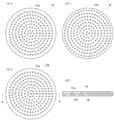
- the perforated plate used for the safety valve is shown, (a-1) is a plan view of the perforated plate 1, and (a-2) is a plan view of the perforated plate in which the positions of the small holes do not match when superposed with the perforated plate 1.
- (b-1) is a plan view (b-2) showing a state in which two perforated plates are superposed, is a sectional view taken along the line AA of (b-1).
- the perforated plate used for the safety valve is shown.
- a safety valve according to another embodiment of the first invention is shown, (a) a front sectional view showing the true identity within a predetermined temperature, and (b) a front sectional view showing a state where the safety valve differential temperature is exceeded. ..
- An example is shown in which the pool portion of the safety valve is formed on the pressing cap side, (a) is a front sectional view showing the true identity within a predetermined temperature, and (b) is a bottom view.
- the discharge direction regulating member of the 2nd invention is shown, (a) is a plan view, (b) is a side view, (c) is a sectional view of BB of (a), and (d) is B- of (a). It is a perspective view of the B cross section.
- ⁇ Embodiment 1> 1 to 3 show an embodiment of the safety valve of the first invention.
- the safety valve 1 shown in FIG. 1 is a safety valve attached to a fluid device 9 having a fluid passage 90 inside and having a discharge passage 91 branched from the fluid passage 90.
- the fluid device 9 is not particularly limited, and examples thereof include a tank for storing fuel hydrogen of a fuel cell vehicle.
- the safety valve 1 is attached to the open end of the discharge passage 91 of the fluid device 9, and forms an inflow passage 20 communicating with the discharge passage 91 and a discharge passage 23 communicating the inflow passage 20 with the outside. And a closing member 3 that blocks the flow of fluid from the inflow passage 20 to the outflow passage 22.
- the inflow path 20 has a larger diameter than the contact portion 21 and the contact portion 21 which abuts on the seal portion 31 formed at the tip portion 30 of the closing member 3 and blocks the flow of fluid from the discharge passage 91 of the fluid device 9. It continues to the open part 22 of.
- the seal portion 31 formed at the tip portion 30 of the closing member 3 is composed of an O-ring 31a and a backup ring 31b, but the tip portion 30 has a truncated cone shape and is in contact with the inflow path 20.
- the fluid can be sealed by using the stepped portion with the contact portion 21 as a valve seat.
- the closing member 3 is urged by an elastic member 32 such as a spring in a direction in which the inflow path 20 and the contact portion 21 communicate with each other.
- the open portion 22 connected to the inflow path 20 is communicated with the discharge path 23 and forms a mounting portion 25 of the pressing cap 4 for fixing the seal portion 31 of the closing member 3 to the abutting portion 21.
- the discharge path 23 is opened in a direction substantially orthogonal to the axis of the main body 2 while the inflow path 20, the contact portion 21 and the open portion 22 are concentric with the axis of the cylindrical main body 2. There is.
- the pressing cap 4 has a male screw portion 41 formed on the peripheral surface and an engaging portion 42 on the top surface for engaging a jig for rotating the pressing cap 4.
- the mounting portion 25 of the main body 2 is designed to engrave a female screw to which a male screw portion 41 formed on the pressing cap is screwed.
- a soluble alloy 6 that melts when a predetermined temperature is reached is deployed between the closing member 3 and the pressing cap 4.
- a pool 8 in which the melted soluble alloy 6 is collected is formed on at least one of the closing member 3 and the pressing cap 4.
- the pool portion 8 is formed on the closing member 3 side. Then, two perforated plates 5A and 5B whose drilling positions do not overlap are arranged between the pool portion 8 and the soluble alloy 6.
- the perforated plate 5 has a large number of small holes 50 drilled in a thin plate (for example, a metal plate having a size of 0.1 to 0.5 mm).
- the outer diameters of the two perforated plates 5A and 5B are the same, but the drilling positions of the small holes 50 are different. It is configured so that it does not overlap.
- the soluble alloy 6 that has flowed into the small holes 50a of the perforated plate 5A that abuts due to the creep phenomenon is in contact with the surface other than the small holes 50b of the second perforated plate 5B, and the flow due to the creep phenomenon is 1. It stays in the small hole 50a of the first perforated plate 5A.
- the fluid passage 90 of the fluid device 9 and the discharge passage 91 branched from the fluid passage 90 are always filled with the fluid flowing through the fluid device 9, and the safety valve 1 attached to the fluid device 9 is filled.
- a fluid pressure is applied to the tip portion 30 of the closing member 3 of the above. Due to this pressure, the soluble alloy 6 flows into the small holes 50a of the porous plate 5A in contact with the soluble alloy 6 by a creep phenomenon, but is blocked by a surface other than the small holes 50b of the porous plate 5B. Then, when a fire or the like occurs and the ambient temperature of the fluid device 9 exceeds a predetermined temperature (melting temperature of the soluble alloy 6), the soluble alloy 6 begins to melt.
- the soluble alloy 6 that has begun to melt becomes liquid, and the small holes 50a of the perforated plate 5A, the gap between the mating surfaces of the perforated plate 5A and the perforated plate 5B, the small holes 50b of the perforated plate 5B, and the perforated plate 5B and the closing member 3 It flows into the pool portion 8 through the gap of the contact surface (in the central portion, it flows directly into the pool portion 8).
- ⁇ Embodiment 2> 4 to 5 show another embodiment of the safety valve of the first invention. This embodiment is configured by attaching the discharge direction regulating member of the second invention shown in FIG. 6 to the main body of the safety valve.
- the safety valve 1 shown in FIG. 4 is a safety valve attached to a fluid device 9 having a fluid passage 90 inside and having a discharge passage 91 branched from the fluid passage 90, as in the first embodiment.
- the inflow passage 20 which is attached to the open end of the discharge passage 91 of the fluid device 9 and communicates the discharge passage 91 with the outside (atmosphere) and the main body 2 forming the discharge passage 23 are blocked and communicated with each other.
- the point that the closing member 3 is provided is the same as that of the first embodiment, and the description thereof will be omitted.
- the safety valve 1 of the present embodiment is composed of an annular body 70 that covers the discharge port 23 of the cylindrical main body 2 of the safety valve 1, and is provided with a circumferential groove 71 on the inner peripheral surface corresponding to the discharge port 23, and the groove 71 is provided.
- a discharge direction regulating member 7 is fitted into the main body 2 so as to open at a predetermined angle ⁇ with respect to the central axis S1 of the annular body 70 communicating with the outside and to form a regulated discharge port 72 communicating with the outside.
- the pool portion 8 is formed on the closing member 3 side as in the first embodiment, but may be formed on the pressing cap 7 side as shown in FIG.
- the shape of the pool portion 8 is such that a long hole (oval type) or the like can be engaged with a jig or tool for fastening the pressing cap 7 to the main body 3. Further, after fastening to the main body 2, the pool portion 8 is sealed with a sealing member such as a vent filter 43.
- the discharge direction regulating member 7 is shown in FIG.
- the discharge direction regulating member 7 is a tubular annular body 70, and is attached to the main body 2 of the inner diameter portion 70a and the inner diameter portion 70a, which are slightly larger than the outer diameter of the portion where the discharge passage 23 of the main body 2 opens.
- a groove portion 71 having a diameter larger than that of the inner diameter portion 70a is formed at a position corresponding to the discharge path 23.
- An annular elastic member for example, an O-ring is provided between the inner diameter portion 70a and the outer peripheral surface of the main body 2, and the attached discharge direction regulating member 7 is fixed to such an extent that it does not easily come off.
- the discharge direction regulating member 7 can freely rotate with respect to the safety valve 1, and the circumferential direction of the fluid discharged from the safety valve 1 can be freely determined.
- the regulated discharge port 72 communicating with the groove portion 71 is provided with a predetermined angle ⁇ with respect to the central axis S1 of the annular body 70, the angle of the fluid discharged from the safety valve 1 in the axial direction is free. Can be decided.
- the safety valve 1 when the mounting location of the safety valve 1 is a fluid device 9 (hydrogen transfer device) of a hydrogen vehicle, the safety valve 1 is arranged on the bottom surface of the fluid device 9.
- the regulated discharge port 72 of the discharge direction regulating member 7 is opened on the lower side ( ⁇ is about 30 to 50 ° with respect to the central axis S1 of the annular body 70).
- the discharge direction regulating member 7 is rotated with respect to the main body 2 and set so that the regulated discharge port 72 faces rearward.
- the fluid (hydrogen) in the fluid device 9 is ejected toward the rear lower side.
- the safety valve of the present invention can be suitably used for a system in which the ambient temperature rises sharply due to a fire or the like and the fluid in the fluid device needs to be discharged to the outside, and a discharge direction regulating member is used. Therefore, it can be suitably used for environmental equipment that needs to regulate the discharge direction of the fluid to be ejected in the event of a fire or the like and prevent the occurrence of a secondary disaster.
- Safety valve 2 Main body 20 Inflow path 21 Contact part 22 Open part 23 Discharge path 24 Mounting part 3 Closure member 30 Tip part 31 Seal part 4 Pressing cap 5 Perforated plate 50 Small hole 6 Soluble alloy 7 Discharge direction regulated 70 Annulus 71 Groove 72 Restricted discharge port 8 Reservoir 9 Fluid equipment 90 Fluid passage 91 Discharge passage
Landscapes
- Engineering & Computer Science (AREA)
- General Engineering & Computer Science (AREA)
- Mechanical Engineering (AREA)
- Safety Valves (AREA)
- Life Sciences & Earth Sciences (AREA)
- Manufacturing & Machinery (AREA)
- Sustainable Development (AREA)
- Sustainable Energy (AREA)
- Chemical & Material Sciences (AREA)
- Chemical Kinetics & Catalysis (AREA)
- Electrochemistry (AREA)
- General Chemical & Material Sciences (AREA)
Priority Applications (5)
| Application Number | Priority Date | Filing Date | Title |
|---|---|---|---|
| US18/019,351 US20240255064A1 (en) | 2020-08-03 | 2021-07-29 | Safety valve and discharge direction regulation member |
| DE112021004132.0T DE112021004132T5 (de) | 2020-08-03 | 2021-07-29 | Sicherheitsventil und ablassrichtungsregelungselement |
| KR1020237006487A KR102872730B1 (ko) | 2020-08-03 | 2021-07-29 | 안전 밸브 및 배출 방향 규제 부재 |
| CA3190462A CA3190462A1 (en) | 2020-08-03 | 2021-07-29 | Safety valve and discharge direction regulation member |
| JP2022541478A JPWO2022030340A1 (https=) | 2020-08-03 | 2021-07-29 |
Applications Claiming Priority (2)
| Application Number | Priority Date | Filing Date | Title |
|---|---|---|---|
| JP2020131563 | 2020-08-03 | ||
| JP2020-131563 | 2020-08-03 |
Publications (1)
| Publication Number | Publication Date |
|---|---|
| WO2022030340A1 true WO2022030340A1 (ja) | 2022-02-10 |
Family
ID=80120050
Family Applications (1)
| Application Number | Title | Priority Date | Filing Date |
|---|---|---|---|
| PCT/JP2021/028003 Ceased WO2022030340A1 (ja) | 2020-08-03 | 2021-07-29 | 安全弁及び排出方向規制部材 |
Country Status (6)
| Country | Link |
|---|---|
| US (1) | US20240255064A1 (https=) |
| JP (1) | JPWO2022030340A1 (https=) |
| KR (1) | KR102872730B1 (https=) |
| CA (1) | CA3190462A1 (https=) |
| DE (1) | DE112021004132T5 (https=) |
| WO (1) | WO2022030340A1 (https=) |
Cited By (1)
| Publication number | Priority date | Publication date | Assignee | Title |
|---|---|---|---|---|
| WO2024247981A1 (ja) * | 2023-06-01 | 2024-12-05 | 株式会社フジキン | 安全弁 |
Families Citing this family (1)
| Publication number | Priority date | Publication date | Assignee | Title |
|---|---|---|---|---|
| AT18429U1 (de) * | 2023-09-05 | 2025-03-15 | Ventrex Automotive Gmbh | Kombinationsventil |
Citations (3)
| Publication number | Priority date | Publication date | Assignee | Title |
|---|---|---|---|---|
| JP2009275862A (ja) * | 2008-05-16 | 2009-11-26 | Kawasaki Precision Machinery Ltd | 安全弁装置 |
| JP2016191435A (ja) * | 2015-03-31 | 2016-11-10 | 日立オートモティブシステムズ株式会社 | 流体圧緩衝器 |
| JP2017180641A (ja) * | 2016-03-30 | 2017-10-05 | 日立建機株式会社 | 減圧弁ユニット |
Family Cites Families (17)
| Publication number | Priority date | Publication date | Assignee | Title |
|---|---|---|---|---|
| GB190901405A (en) * | 1909-01-20 | 1910-01-06 | William Hans Milde | Improvements in or relating to Venting Apparatus for Cans, Tanks or the like for Containing Volatile and other Inflammable Liquids. |
| US5511576A (en) * | 1995-01-17 | 1996-04-30 | Amcast Industrial Corporation | Piston-type thermally activated relief device |
| US5495865A (en) * | 1995-03-28 | 1996-03-05 | Mirada Controls, Inc. | Temperature relief valve with thermal trigger |
| JP3038681B2 (ja) | 1995-12-13 | 2000-05-08 | サンデン株式会社 | 圧縮機の安全弁 |
| US6367499B2 (en) * | 2000-03-02 | 2002-04-09 | Hamai Industries Limited | Safety valve |
| US6814097B2 (en) * | 2001-03-20 | 2004-11-09 | Teleflex Gfi Control Systems L.P. | Pressure relief device |
| JP3820483B2 (ja) * | 2003-03-03 | 2006-09-13 | 株式会社フジキン | 安全弁 |
| JP4427371B2 (ja) * | 2004-03-29 | 2010-03-03 | 株式会社ネリキ | 安全弁 |
| EP1830115B1 (en) * | 2004-11-11 | 2014-03-26 | Kawasaki Jukogyo Kabushiki Kaisha | Safety valve device |
| DE102010011878A1 (de) * | 2010-03-18 | 2011-09-22 | Hydac Technology Gmbh | Sicherheitseinrichtung für durch Gasdruck belastete Behälter |
| JP5775688B2 (ja) | 2010-12-20 | 2015-09-09 | 株式会社フジキン | 安全弁用可溶栓 |
| EP3042110B1 (en) * | 2013-09-03 | 2017-07-12 | Pentair Flow Control AG | Relief valve with directable outlet |
| JP6387273B2 (ja) | 2014-09-05 | 2018-09-05 | 株式会社フジキン | 安全弁 |
| CN107289163A (zh) * | 2017-06-30 | 2017-10-24 | 上海百图低温阀门有限公司 | 车用高压压缩氢气瓶用安全装置 |
| JP7246964B2 (ja) | 2019-02-20 | 2023-03-28 | ローランドディー.ジー.株式会社 | インクジェットプリンタおよび検出方法 |
| KR102805102B1 (ko) * | 2019-05-17 | 2025-05-08 | 현대자동차주식회사 | 연료전지 차량의 온도감응식 압력안전장치 |
| KR102515443B1 (ko) * | 2021-06-23 | 2023-03-29 | 영도산업 주식회사 | 고압용기용 압력해제장치 |
-
2021
- 2021-07-29 DE DE112021004132.0T patent/DE112021004132T5/de active Pending
- 2021-07-29 KR KR1020237006487A patent/KR102872730B1/ko active Active
- 2021-07-29 US US18/019,351 patent/US20240255064A1/en not_active Abandoned
- 2021-07-29 CA CA3190462A patent/CA3190462A1/en active Pending
- 2021-07-29 WO PCT/JP2021/028003 patent/WO2022030340A1/ja not_active Ceased
- 2021-07-29 JP JP2022541478A patent/JPWO2022030340A1/ja active Pending
Patent Citations (3)
| Publication number | Priority date | Publication date | Assignee | Title |
|---|---|---|---|---|
| JP2009275862A (ja) * | 2008-05-16 | 2009-11-26 | Kawasaki Precision Machinery Ltd | 安全弁装置 |
| JP2016191435A (ja) * | 2015-03-31 | 2016-11-10 | 日立オートモティブシステムズ株式会社 | 流体圧緩衝器 |
| JP2017180641A (ja) * | 2016-03-30 | 2017-10-05 | 日立建機株式会社 | 減圧弁ユニット |
Cited By (3)
| Publication number | Priority date | Publication date | Assignee | Title |
|---|---|---|---|---|
| WO2024247981A1 (ja) * | 2023-06-01 | 2024-12-05 | 株式会社フジキン | 安全弁 |
| KR20250168547A (ko) | 2023-06-01 | 2025-12-02 | 가부시키가이샤 후지킨 | 안전 밸브 |
| DE112024002381T5 (de) | 2023-06-01 | 2026-03-12 | Fujikin Incorporated | Sicherheitsventil |
Also Published As
| Publication number | Publication date |
|---|---|
| KR102872730B1 (ko) | 2025-10-16 |
| DE112021004132T5 (de) | 2023-07-20 |
| CA3190462A1 (en) | 2022-02-10 |
| JPWO2022030340A1 (https=) | 2022-02-10 |
| KR20230041104A (ko) | 2023-03-23 |
| US20240255064A1 (en) | 2024-08-01 |
Similar Documents
| Publication | Publication Date | Title |
|---|---|---|
| JP7496881B2 (ja) | 圧縮ガス貯留装置、車両 | |
| US8550105B2 (en) | Valve system of high pressure tank for vehicle | |
| US10529969B2 (en) | Pressure relief mechanism, case, and pressure relief valve | |
| EP1323928B1 (en) | Accumulator having a safety valve | |
| JP4996990B2 (ja) | 逃がし弁 | |
| US9133942B2 (en) | Valve structure for fluid pressure device | |
| WO2022030340A1 (ja) | 安全弁及び排出方向規制部材 | |
| CN108028338A (zh) | 压力平衡装置 | |
| EP3739249B1 (en) | Thermal-activated pressure relief device for fuel cell vehicle | |
| JPWO2022030340A5 (https=) | ||
| JP4427371B2 (ja) | 安全弁 | |
| CA3181435A1 (en) | Pressure vessel with multiple lateral outflow openings | |
| JP4877947B2 (ja) | リリーフ弁及び燃料電池システム | |
| KR20250168547A (ko) | 안전 밸브 | |
| JP2018028335A (ja) | 弁装置 | |
| JP2021111266A (ja) | 逃し弁一体減圧弁及び給湯機 | |
| JP7381011B2 (ja) | 安全弁 | |
| KR102690527B1 (ko) | 고압 용기용 압력 해제장치 | |
| EP4209701B1 (en) | Safety joint | |
| JP2002257297A (ja) | 高圧ガス容器用安全装置 | |
| CA3028761C (en) | Method for capping a cylinder valve | |
| US6776181B2 (en) | Safety valve for pressurized fluid tanks | |
| CA3028776C (en) | Apparatus for capping a cylinder valve | |
| JP2004270809A (ja) | 安全弁 | |
| US5551471A (en) | Valve with consumable vent hole seal device |
Legal Events
| Date | Code | Title | Description |
|---|---|---|---|
| 121 | Ep: the epo has been informed by wipo that ep was designated in this application |
Ref document number: 21853514 Country of ref document: EP Kind code of ref document: A1 |
|
| ENP | Entry into the national phase |
Ref document number: 2022541478 Country of ref document: JP Kind code of ref document: A |
|
| ENP | Entry into the national phase |
Ref document number: 3190462 Country of ref document: CA |
|
| WWE | Wipo information: entry into national phase |
Ref document number: 18019351 Country of ref document: US |
|
| ENP | Entry into the national phase |
Ref document number: 20237006487 Country of ref document: KR Kind code of ref document: A |
|
| 122 | Ep: pct application non-entry in european phase |
Ref document number: 21853514 Country of ref document: EP Kind code of ref document: A1 |