WO2022029909A1 - 光コネクタ - Google Patents
光コネクタ Download PDFInfo
- Publication number
- WO2022029909A1 WO2022029909A1 PCT/JP2020/029925 JP2020029925W WO2022029909A1 WO 2022029909 A1 WO2022029909 A1 WO 2022029909A1 JP 2020029925 W JP2020029925 W JP 2020029925W WO 2022029909 A1 WO2022029909 A1 WO 2022029909A1
- Authority
- WO
- WIPO (PCT)
- Prior art keywords
- mode
- optical connector
- connector
- cavity
- optical fiber
- Prior art date
- Legal status (The legal status is an assumption and is not a legal conclusion. Google has not performed a legal analysis and makes no representation as to the accuracy of the status listed.)
- Ceased
Links
Images





Classifications
-
- G—PHYSICS
- G02—OPTICS
- G02B—OPTICAL ELEMENTS, SYSTEMS OR APPARATUS
- G02B6/00—Light guides; Structural details of arrangements comprising light guides and other optical elements, e.g. couplings
- G02B6/24—Coupling light guides
- G02B6/36—Mechanical coupling means
- G02B6/38—Mechanical coupling means having fibre to fibre mating means
- G02B6/3807—Dismountable connectors, i.e. comprising plugs
- G02B6/3833—Details of mounting fibres in ferrules; Assembly methods; Manufacture
- G02B6/3845—Details of mounting fibres in ferrules; Assembly methods; Manufacture ferrules comprising functional elements, e.g. filters
-
- G—PHYSICS
- G02—OPTICS
- G02B—OPTICAL ELEMENTS, SYSTEMS OR APPARATUS
- G02B6/00—Light guides; Structural details of arrangements comprising light guides and other optical elements, e.g. couplings
- G02B6/02—Optical fibres with cladding with or without a coating
- G02B6/028—Optical fibres with cladding with or without a coating with core or cladding having graded refractive index
- G02B6/0288—Multimode fibre, e.g. graded index core for compensating modal dispersion
-
- G—PHYSICS
- G02—OPTICS
- G02B—OPTICAL ELEMENTS, SYSTEMS OR APPARATUS
- G02B6/00—Light guides; Structural details of arrangements comprising light guides and other optical elements, e.g. couplings
- G02B6/24—Coupling light guides
- G02B6/36—Mechanical coupling means
- G02B6/38—Mechanical coupling means having fibre to fibre mating means
- G02B6/3807—Dismountable connectors, i.e. comprising plugs
- G02B6/381—Dismountable connectors, i.e. comprising plugs of the ferrule type, e.g. fibre ends embedded in ferrules, connecting a pair of fibres
- G02B6/3825—Dismountable connectors, i.e. comprising plugs of the ferrule type, e.g. fibre ends embedded in ferrules, connecting a pair of fibres with an intermediate part, e.g. adapter, receptacle, linking two plugs
-
- G—PHYSICS
- G02—OPTICS
- G02B—OPTICAL ELEMENTS, SYSTEMS OR APPARATUS
- G02B6/00—Light guides; Structural details of arrangements comprising light guides and other optical elements, e.g. couplings
- G02B6/02—Optical fibres with cladding with or without a coating
- G02B6/032—Optical fibres with cladding with or without a coating with non solid core or cladding
-
- G—PHYSICS
- G02—OPTICS
- G02B—OPTICAL ELEMENTS, SYSTEMS OR APPARATUS
- G02B6/00—Light guides; Structural details of arrangements comprising light guides and other optical elements, e.g. couplings
- G02B6/24—Coupling light guides
- G02B6/26—Optical coupling means
- G02B6/264—Optical coupling means with optical elements between opposed fibre ends which perform a function other than beam splitting
- G02B6/266—Optical coupling means with optical elements between opposed fibre ends which perform a function other than beam splitting the optical element being an attenuator
Definitions
- the present disclosure relates to an optical connector that compensates for a gain difference between modes of signal light propagating in a transmission line.
- Multi mode fiber MMF
- MMF multimode fiber
- Non-Patent Document 3 In order to extend the distance of mode multiplex transmission, the difference in loss between modes (Differential modal attenuation: DMA) generated in the transmission line and the difference in gain between modes (Differential) generated in the optical amplifier (Differential) are generated in order to perform long-distance transmission. Modal gain (DMG) becomes important. Also in order to realize long-distance transmission, the loss difference between modes (Mode dependent loss: MDL) including DMA and DMG is adjusted to 0.2 dB or less in one span. .. In Non-Patent Document 3, a spatial filter type inter-mode loss difference compensator is used to give a loss of about 3 dB to the LP01 mode as compared with the LP11 mode, thereby contributing to the reduction of the MDL.
- Non-Patent Document 3 uses a lens, a filter for giving a loss to a specific mode, and the like in addition to the fiber, so that the structure is complicated and the propagation mode is used. There is a problem that precise alignment work is required to suppress crosstalk.
- the optical fiber is fused and connected to the optical fiber of the transmission line in advance to construct a transmission line, so that the transmission line may be inserted after construction. difficult. Therefore, in this method, the MDL of the transmission line is predicted in advance, and an optical fiber capable of reducing the MDL is prepared to construct the transmission line. That is, the method has a problem that it is difficult to sufficiently obtain the effect of reducing the MDL of the transmission line when the predicted MDL is not accurate.
- an object of the present invention is to provide a simple method capable of reducing MDL after constructing a transmission line in order to solve the above problems.
- this specification discloses an optical connector that can reduce MDL by connecting to a transmission line.
- the optical connector according to the present invention is an optical connector including a multimode optical fiber, and the core of the multimode optical fiber is characterized by having a plurality of cavities along a central axis.
- a plurality of optical connectors having different loss ratios between the basic mode and the higher-order mode are prepared in advance, the MDL of the constructed transmission line is measured, an optical connector capable of improving the MDL is selected, and the optical connector is connected to the transmission line. Therefore, the present invention can provide a simple method (optical connector) that can reduce MDL after constructing a transmission line.
- the cavity of the optical connector according to the present invention is an ellipsoid, and the major axis direction of one cavity is different from the major axis direction of the other cavity. If the cavity is an ellipsoid, a loss difference between the degenerate modes of the higher order mode may occur. In such a case, by changing the long axis direction of the ellipsoid for each cavity, the loss between the degenerate modes of the higher-order mode can be averaged and the loss difference can be reduced.
- the present invention can provide a simple method (optical connector) that can reduce MDL after constructing a transmission line.
- FIG. 1 is a cross-sectional view illustrating the structure of the optical connector 301 of the present embodiment.
- the optical connector 301 is an optical connector including a multimode optical fiber 11, and the core 20 of the multimode optical fiber 11 is characterized by having a plurality of cavities 25 along a central axis.
- the optical connector 301 further includes a ferrule 12 including a multimode optical fiber 11 and a connector plug 13 for connecting to another optical connector.
- the shape of the optical connector 13 is a shape of a generally used SC connector, FC connector, MT connector, or the like.
- FIG. 2 is a diagram illustrating a core cross section (a) and a refractive index distribution (b) of the multimode optical fiber 11 capable of compensating for loss difference.
- the z direction is the optical axis direction (the central axis direction of the multimode optical fiber 301).
- FIG. 2 is a cross-sectional view of a portion where the cavity 25 exists.
- the cross section of the part where the cavity does not exist is a uniform core region.
- the core radius, the cavity radius, the refractive index of the core, and the refractive index of the clad are set to a1, a2, n1, and n2, respectively.
- ⁇ (n1 2 ⁇ n2 2 ) / 2n1 2 .
- the confinement tends to be stronger in the basic mode than in the higher order mode, and the propagation loss including bending loss tends to be smaller. Therefore, in order to reduce the MDL in the mode multiplex transmission system, a structure in which a larger excess loss than the higher-order mode is given to the basic mode will be described. Further, in the present embodiment, the example in which the multimode optical fiber has two LP modes will be described, but the case where the number of modes increases can be considered in the same manner.
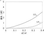
- FIG. 3 is a diagram illustrating the relationship between the loss in the LP01 mode and the LP11 mode with respect to the ratio of the cavity radius a2 and the core radius a1.
- the a2 / a1 ratio becomes large (the cavity radius becomes large with respect to the core radius), the loss becomes large in both modes, but the loss is larger in the LP01 mode. Therefore, by controlling the a2 / a1 ratio, it is possible to set the range of MDL that can be compensated by the optical connector 301.
- the loss in either mode is proportional to the number of cavities. Therefore, the amount of loss can be set by controlling the number of cavities.
- FIG. 4 shows data when the radii of the cavities 25 are the same, cavities 25 having different radii may be arranged.
- the optical connector 301 is a cavity-imparted mode-to-mode loss difference compensation connector.
- the optical connector 301 is inserted into one or more connection portions in the constructed transmission line to compensate the MDL of the transmission line.
- the MDL of the transmission line is measured, and an optical connector 301 having a characteristic of eliminating the MDL is connected to a connection portion of the transmission line (see FIG. 8).
- an optical connector 301 having a characteristic of eliminating the MDL is connected to a connection portion of the transmission line (see FIG. 8).
- the MDL can be reduced without fusing the optical fiber that can estimate the MDL before constructing the transmission line and reduce the MDL as in the past.
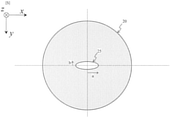
- FIG. 5 is a cross section of the core of the multimode optical fiber 11 and is a diagram illustrating a case where the cavity 25 is an ellipsoid.
- the z direction is the optical axis direction (the central axis direction of the multimode optical fiber 301).
- the cavity 25 is an ellipsoid having a major axis (radius a) in the x direction and a minor axis (radius b) in the y direction.
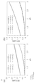
- FIG. 7A is a diagram illustrating the dependence of the polarization degeneracy mode of the LP01 mode and the LP11 mode due to the cavity of the ellipsoid.
- the loss in the LP11a mode is larger than that in the LP11b in both the x-direction and the y-direction. That is, it can be said that the loss given to the mode differs depending on the shape of the cavity 25.
- FIG. 6 is a diagram in which two core cross sections of the multimode optical fiber 11 of the present embodiment are overlapped.
- FIG. 7B is a diagram illustrating a loss difference between degenerate modes when two cavities 25 are created by shifting the major axis by 90 ° as shown in FIG.
- FIG. 7A there was a loss difference between LP11a and LP11b, but in FIG. 7B, the loss difference between the two is eliminated. That is, it can be seen that the degeneracy mode dependence of the LP11 mode can be greatly improved by arranging the cavities that are ellipsoids in different directions in the major axis direction.
- the number of cavities 25 is two has been described, but the number of cavities 25 is not limited to two and may be three or more. Further, in that case, the amount of deviation of the long axis of each cavity is not limited to 90 °. For example, if the number of cavities is N, the amount of deviation of the major axis of the cavities can be set to 180 ° / N. Further, the cavities 25 may have different major axis directions from each other, or may have different major axis directions for each plurality.
- a connector having an optical fiber having a cavity can give an arbitrary loss difference according to the transmission line and control the loss difference of the transmission line. [The invention's effect] By forming a cavity inside the optical connector, it is possible to easily add a loss difference at the connection point even after the transmission path is constructed.
- Multimode optical fiber 12 Ferrule 13: Connector plug 20: Core 25, 25-1, 25-2: Cavity 301: Optical connector
Landscapes
- Physics & Mathematics (AREA)
- General Physics & Mathematics (AREA)
- Optics & Photonics (AREA)
- Chemical & Material Sciences (AREA)
- Dispersion Chemistry (AREA)
- Optical Couplings Of Light Guides (AREA)
- Mechanical Coupling Of Light Guides (AREA)
- Optical Fibers, Optical Fiber Cores, And Optical Fiber Bundles (AREA)
Abstract
本発明は、伝送路構築後にMDLを低減できる簡易な手法を提供することを目的とする。 光コネクタ301は、マルチモード光ファイバ11を備える光コネクタであって、マルチモード光ファイバ11のコア20は、中心軸に沿って複数の空洞25を有することを特徴とする。光コネクタ301は、さらに、マルチモード光ファイバ11を内包するフェルール12、及び他の光コネクタとの接続を担うコネクタプラグ13を備える。光コネクタ13の形状は、一般的に使用されているSCコネクタ、FCコネクタ、MTコネクタ等の形状である。
Description
本開示は、伝送路を伝搬する信号光のモード間利得差を補償する光コネクタに関する。
近年、サービスの多様化によりインターネットトラヒックは未だ増加し続けており、伝送速度の高速化や波長分割多重(Wavelength Division Multiplexing:WDM)技術による波長多重数の増加により飛躍的に伝送容量を伸ばしてきた。また近年、検討が盛んに行われているデジタルコヒーレント技術によって更なる伝送容量の拡大が予想されている。デジタルコヒーレント伝送システムでは多値位相変調信号を用いることにより周波数利用効率を向上させてきたが、より高い信号雑音比が必要となってくる。しかし従来のシングルモードファイバ(Single mode fiber、 SMF)を用いた伝送システムでは、理論的な限界に加え非線形効果に起因する入力パワー制限のため伝送容量は100 Tbit/secを境に飽和することが予想されており、更なる大容量化は困難となってきている。
今後さらに伝送容量を増やしていくためには革新的な伝送容量拡大を実現する媒体が必要とされている。そこで、光ファイバ中の複数の伝搬モードをチャネルとして用いることで信号雑音比と空間利用効率の向上が期待できるマルチモードファイバ(Multi mode fiber、 MMF)を用いたモード多重伝送が注目を集めている。これまでファイバ中を伝搬する高次のモードは信号劣化の要因であったが、デジタル信号処理や合分波技術などの発展で積極的な利用が検討されている(例えば、非特許文献1、2を参照。)。
伝送容量の拡大に加えモード多重伝送の長距離化に向けた検討も行われており、3モード伝搬可能な非結合型の12コアファイバを用いた527km伝送の報告がなされている(例えば、非特許文献3を参照。)。
N.Hanzawa et al., "Demonstration of Mode-Division multiplexing Transmission Over 10 km Two-mode Fiber with Mode Coupler" OFC2011, paper OWA4
T.Sakamoto et al., "Modal Dispersion Technique for Long-haul Transmission over Few-mode Fiber with SIMO Configuration" ECOC2011, We.10.P1.82
K. Shibahara et al. "Dense SDM (12-Core × 3-Mode) Transmission Over 527 km With 33.2-ns Mode-Dispersion Employing Low-Complexity Parallel MIMO Frequency-Domain Equalization," J. Lightw. Technol., vol.34, no. 1 (2016).
X. Zhao et al. "Mode converter based on the long-period fiber gratings written in the six-mode fiber," ICOCN, 2017.
T. Fujisawa et al.,"One chip,PLC three-mode exchanger based on symmetric and asymmetric directional couplers with integrated mode rotator," OFC 2017,Paper.W1b.2.
M. Salsi et al.,"A Six-mode erbium-doped fiber amplifier,"ECOC 2012,Paper. Th.3.A.6.
Y. Jung et al.,"Reconfigurable modal gain control of a few-mode EDFA supporting six spatial modes," IEEE Photonics Technology Letters, vol.26,No.11,June (2014)
モード多重伝送の長距離化を行う上で、長距離伝送を行うためには伝送路にて発生するモード間損失差(Differential modal attenuation:DMA)や光増幅器にて発生するモード間利得差(Differential modal gain:DMG)が重要となってくる。非特許文献3においても長距離伝送を実現するためにDMA及びDMGを含めたモード間損失差(Mode dependent loss:MDL)を1スパンの中で0.2dB以下になるように調整を行っている。非特許文献3においては空間フィルタ型のモード間損失差補償器を用いてLP01モードにLP11モードに比べ3dB程度大きい損失を与えることでMDLの低減に寄与している。
しかし、非特許文献3のような空間型の利得等化器は、ファイバ以外に、レンズや特定のモードに損失を与えるためのフィルタ等を用いるため、構造が複雑である、及び伝搬モード間のクロストーク抑制するために精密なアライメント作業が必要であるという課題があった。
また、コア内に空洞を有する光ファイバでMDLを低減する手法は、当該光ファイバを伝送路の光ファイバと予め融着接続して伝送路を構築するため、伝送路を構築後に挿入することが難しい。このため、当該手法は、事前に伝送路のMDLを予測し、そのMDLを低減できる光ファイバを用意して伝送路を構築する。つまり、当該手法には、予測したMDLが正確でない場合、伝送路のMDLの低減効果を十分に得ることが困難という課題がある。
そこで、本発明は、上記課題を解決するために、伝送路構築後にMDLを低減できる簡易な手法を提供することを目的とする。
上記目的を達成するために、本明細書は、伝送路に接続することでMDLを低減できる光コネクタを開示する。
具体的には、本発明に係る光コネクタは、マルチモード光ファイバを備える光コネクタであって、前記マルチモード光ファイバのコアは、中心軸に沿って複数の空洞を有することを特徴とする。予め基本モードと高次モードとの損失比が異なる光コネクタを複数用意しておき、構築された伝送路のMDLを測定し、当該MDLを改善できる光コネクタを選択して伝送路に接続する。従って、本発明は、伝送路構築後にMDLを低減できる簡易な手法(光コネクタ)を提供することができる。
また、本発明に係る光コネクタの前記空洞は、楕円体であり、1つの前記空洞の長軸方向が他の前記空洞の長軸方向と異なることを特徴とする。空洞部が楕円体である場合、高次モードの縮退モード間の損失差が発生することがある。このような場合、楕円体の長軸方向を空洞部毎に変えることで高次モードの縮退モード間の損失を平均し、その損失差を低減することができる。
本発明は、伝送路構築後にMDLを低減できる簡易な手法(光コネクタ)を提供することができる。
添付の図面を参照して本発明の実施形態を説明する。以下に説明する実施形態は本発明の実施例であり、本発明は、以下の実施形態に制限されるものではない。なお、本明細書及び図面において符号が同じ構成要素は、相互に同一のものを示すものとする。
(実施形態1)
図1は、本実施形態の光コネクタ301の構造を説明する断面図である。光コネクタ301は、マルチモード光ファイバ11を備える光コネクタであって、マルチモード光ファイバ11のコア20は、中心軸に沿って複数の空洞25を有することを特徴とする。光コネクタ301は、さらに、マルチモード光ファイバ11を内包するフェルール12、及び他の光コネクタとの接続を担うコネクタプラグ13を備える。光コネクタ13の形状は、一般的に使用されているSCコネクタ、FCコネクタ、MTコネクタ等の形状である。
図1は、本実施形態の光コネクタ301の構造を説明する断面図である。光コネクタ301は、マルチモード光ファイバ11を備える光コネクタであって、マルチモード光ファイバ11のコア20は、中心軸に沿って複数の空洞25を有することを特徴とする。光コネクタ301は、さらに、マルチモード光ファイバ11を内包するフェルール12、及び他の光コネクタとの接続を担うコネクタプラグ13を備える。光コネクタ13の形状は、一般的に使用されているSCコネクタ、FCコネクタ、MTコネクタ等の形状である。
図2は、損失差補償を行えるマルチモード光ファイバ11のコア断面(a)とその屈折率分布(b)を説明する図である。ここで、z方向は光軸方向(マルチモード光ファイバ301の中心軸方向)である。なお、図2は、空洞25が存在する部分の断面図である。空洞が存在しない部分の断面は一様なコア領域となる。ここで、コア半径、空洞半径、コアの屈折率、クラッドの屈折率をそれぞれa1,a2,n1,n2とする。また、コアのクラッドに対する比屈折率差Δを
Δ=(n12-n22)/2n12
とする。
Δ=(n12-n22)/2n12
とする。
一般的にマルチモード光ファイバにおいては、高次モードに比べ基本モードは閉じ込めが強くなり曲げ損失を含む伝搬損失が小さくなる傾向がある。そこでモード多重伝送システムにおいてMDLを小さくするために、基本モードに対して高次モードより大きな過剰損失を与えられる構造について説明する。また、本実施形態ではマルチモード光ファイバのLPモードが2つである例で説明するが、モード数が増加した場合も同様に考えることができる。
図3は、空洞半径a2とコア半径a1の比率に対するLP01モードとLP11モードの損失の関係を説明する図である。a2/a1比率が大きくなる(空洞半径がコア半径に対して大きくなる)といずれのモードも損失が大きくなるが、LP01モードの方が損失が大きい。従って、a2/a1比率を制御することで、光コネクタ301で補償できるMDLの範囲を設定することができる。
図4は、比率a2/a1=0.2とした場合の、空洞数と各モードの損失の関係を説明する図である。いずれのモードの損失も空洞数に比例する。従って、空洞数を制御することで損失量を設定することができる。なお、図4では、各空洞25の半径が等しい場合のデータを示しているが、半径の異なる空洞25を配列してもよい。
図3と図4を考慮することで、a2/a1比率と形成する空洞数を調整して、様々なモード間損失差の光コネクタ301を製造することができる。
上述のように、光コネクタ301は、空洞付与型モード間損失差補償用コネクタである。構築されている伝送路中の1か所以上の接続部に光コネクタ301を挿入し、当該伝送路のMDLを補償する。作業手順としては、例えば、伝送路を構築した後に当該伝送路のMDLを測定し、当該MDLを解消する特性の光コネクタ301を伝送路の接続部に接続する(図8参照。)。また、光コネクタ301を複数個組み合わせて多段に接続することで、伝送路に合わせた任意のモード間損失差を付与することもできる。
このように、光コネクタ301を使用することで、従前のように伝送路構築前にMDLを推定して当該MDLを低減できる光ファイバを融着することなく、MDLを低減することができる。
(実施形態2)
実施形態1で説明したマルチモード光ファイバ11の空洞25を、光ファイバ側面からフェムト秒レーザ加工で形成しようとすると、焦点収差により空洞が楕円形状に歪むことがある。図5は、マルチモード光ファイバ11のコア断面であって、空洞25が楕円体である場合を説明する図である。ここで、z方向は光軸方向(マルチモード光ファイバ301の中心軸方向)である。本図では、空洞25はx方向を長軸(半径a)、y方向を短軸(半径b)とする楕円体となっている。
実施形態1で説明したマルチモード光ファイバ11の空洞25を、光ファイバ側面からフェムト秒レーザ加工で形成しようとすると、焦点収差により空洞が楕円形状に歪むことがある。図5は、マルチモード光ファイバ11のコア断面であって、空洞25が楕円体である場合を説明する図である。ここで、z方向は光軸方向(マルチモード光ファイバ301の中心軸方向)である。本図では、空洞25はx方向を長軸(半径a)、y方向を短軸(半径b)とする楕円体となっている。
このような楕円体の空洞が存在すると、LP11モードの縮退モード依存性が増大することがある。図7(a)は、楕円体の空洞によるLP01モード及びLP11モードの偏波縮退モードの依存性を説明する図である。LP01モードについては、x方向もy方向も損失に大きな差はない。しかし、LP11モードは、LP11aモードの方がx方向もy方向もLP11bよりも損失が大きい。すなわち、空洞25の形状によってモードに与えられる損失が異なるといえる。
そこで、本実施形態では、図7(a)のようなLP11モードの縮退モード依存性を解消するために、1つの空洞の長軸方向が他の空洞の長軸方向と異なることとした。図6は、本実施形態のマルチモード光ファイバ11のコア断面を2つ重ねた図である。本実施形態は、空洞25-1の長軸方向と空洞25-2の長軸方向とが90°ずれた例(θ=90°)である。
フェムト秒レーザの照射方向を変え、長軸を90°ずらして空洞25を2つ作成することで、図7(a)で説明したような楕円体による非対称性を改善することができる。図7(b)は、図6のように長軸を90°ずらして空洞25を2つ作成した場合の縮退モード間の損失差を説明する図である。図7(a)ではLP11aとLP11bとの損失差があったが、図7(b)では両者の損失差が解消されている。つまり、楕円体である空洞の長軸方向を違えて配列することでLP11モードの縮退モード依存性が大きく改善できることがわかる。
本実施形態は、空洞25が2つの場合を説明したが、空洞25の数は2つに限らず3以上でもよい。また、その場合、それぞれの空洞の長軸のずれ量は90°に限らない。例えば、空洞数がN個であれば、空洞の長軸のずれ量を180°/Nとすることができる。また、空洞25は、長軸方向が互いに異なっていてもよいし、複数個毎に長軸方向を違えてもよい。
[発明のポイント]
空洞を有する光ファイバを有するコネクタによって、伝送路に合わせて任意の損失差を付与し、伝送路の損失差を制御することができる。
[発明の効果]
光コネクタの内部に空洞部を作製することで、接続点において伝送路構築後にも容易に損失差を付与することができる。
空洞を有する光ファイバを有するコネクタによって、伝送路に合わせて任意の損失差を付与し、伝送路の損失差を制御することができる。
[発明の効果]
光コネクタの内部に空洞部を作製することで、接続点において伝送路構築後にも容易に損失差を付与することができる。
11:マルチモード光ファイバ
12:フェルール
13:コネクタプラグ
20:コア
25、25-1、25-2:空洞
301:光コネクタ
12:フェルール
13:コネクタプラグ
20:コア
25、25-1、25-2:空洞
301:光コネクタ
Claims (2)
- マルチモード光ファイバを備える光コネクタであって、
前記マルチモード光ファイバのコアは、中心軸に沿って複数の空洞を有することを特徴とする光コネクタ。 - 前記空洞は、楕円体であり、1つの前記空洞の長軸方向が他の前記空洞の長軸方向と異なることを特徴とする請求項1に記載の光コネクタ。
Priority Applications (3)
| Application Number | Priority Date | Filing Date | Title |
|---|---|---|---|
| PCT/JP2020/029925 WO2022029909A1 (ja) | 2020-08-05 | 2020-08-05 | 光コネクタ |
| JP2022541393A JP7468664B2 (ja) | 2020-08-05 | 2020-08-05 | 光コネクタ |
| US18/019,193 US20230305223A1 (en) | 2020-08-05 | 2020-08-05 | Optical connector |
Applications Claiming Priority (1)
| Application Number | Priority Date | Filing Date | Title |
|---|---|---|---|
| PCT/JP2020/029925 WO2022029909A1 (ja) | 2020-08-05 | 2020-08-05 | 光コネクタ |
Publications (1)
| Publication Number | Publication Date |
|---|---|
| WO2022029909A1 true WO2022029909A1 (ja) | 2022-02-10 |
Family
ID=80117914
Family Applications (1)
| Application Number | Title | Priority Date | Filing Date |
|---|---|---|---|
| PCT/JP2020/029925 Ceased WO2022029909A1 (ja) | 2020-08-05 | 2020-08-05 | 光コネクタ |
Country Status (3)
| Country | Link |
|---|---|
| US (1) | US20230305223A1 (ja) |
| JP (1) | JP7468664B2 (ja) |
| WO (1) | WO2022029909A1 (ja) |
Citations (4)
| Publication number | Priority date | Publication date | Assignee | Title |
|---|---|---|---|---|
| US20140301707A1 (en) * | 2013-04-09 | 2014-10-09 | Institut National D'optique | Optical waveguide, mode scrambler and mode conditioner for controlling mode power distribution |
| JP2018092053A (ja) * | 2016-12-06 | 2018-06-14 | 日本電信電話株式会社 | 光ファイバ接続方法および接続構造 |
| JP2020024271A (ja) * | 2018-08-07 | 2020-02-13 | 日本電信電話株式会社 | モード間損失差補償用ファイバ、光増幅器、および伝送路設計方法 |
| US20200166698A1 (en) * | 2017-08-07 | 2020-05-28 | Oxford University Innovation Limited | Method of laser modification of an otpical fibre |
Family Cites Families (3)
| Publication number | Priority date | Publication date | Assignee | Title |
|---|---|---|---|---|
| DE102009041891A1 (de) * | 2009-09-18 | 2011-03-31 | Fraunhofer-Gesellschaft zur Förderung der angewandten Forschung e.V. | Transversalmodenfilter für Wellenleiter |
| US10295845B2 (en) * | 2016-09-29 | 2019-05-21 | Nlight, Inc. | Adjustable beam characteristics |
| WO2022054182A1 (ja) * | 2020-09-09 | 2022-03-17 | 日本電信電話株式会社 | 長周期ファイバグレーティング及び光伝送システム |
-
2020
- 2020-08-05 US US18/019,193 patent/US20230305223A1/en not_active Abandoned
- 2020-08-05 WO PCT/JP2020/029925 patent/WO2022029909A1/ja not_active Ceased
- 2020-08-05 JP JP2022541393A patent/JP7468664B2/ja active Active
Patent Citations (4)
| Publication number | Priority date | Publication date | Assignee | Title |
|---|---|---|---|---|
| US20140301707A1 (en) * | 2013-04-09 | 2014-10-09 | Institut National D'optique | Optical waveguide, mode scrambler and mode conditioner for controlling mode power distribution |
| JP2018092053A (ja) * | 2016-12-06 | 2018-06-14 | 日本電信電話株式会社 | 光ファイバ接続方法および接続構造 |
| US20200166698A1 (en) * | 2017-08-07 | 2020-05-28 | Oxford University Innovation Limited | Method of laser modification of an otpical fibre |
| JP2020024271A (ja) * | 2018-08-07 | 2020-02-13 | 日本電信電話株式会社 | モード間損失差補償用ファイバ、光増幅器、および伝送路設計方法 |
Also Published As
| Publication number | Publication date |
|---|---|
| US20230305223A1 (en) | 2023-09-28 |
| JP7468664B2 (ja) | 2024-04-16 |
| JPWO2022029909A1 (ja) | 2022-02-10 |
Similar Documents
| Publication | Publication Date | Title |
|---|---|---|
| JP7095473B2 (ja) | モード間損失差補償用ファイバ、および光増幅器 | |
| US10782478B2 (en) | Inter-mode loss difference compensator and optical amplifier | |
| JP5242405B2 (ja) | 光ファイバおよび光ファイバ伝送路 | |
| US7773845B2 (en) | Optical fiber and optical-fiber transmission line | |
| JP7359296B2 (ja) | モード間損失差補償器 | |
| JP2011027773A (ja) | 光ミキサー | |
| JPH10253847A (ja) | 分散補償光ファイバ | |
| JP6368279B2 (ja) | 数モード光ファイバ、及び光ファイバ伝送システム | |
| JP5079664B2 (ja) | 光波長分割多重通信システム並びに励振器及びモードフィルタ | |
| JP2017191185A (ja) | モード合分波器、光伝送システム及び中継伝送システム | |
| JP6571562B2 (ja) | 増幅用光ファイバの設計方法 | |
| JP6939728B2 (ja) | マルチモード光増幅器 | |
| JP6092029B2 (ja) | マルチモード光ファイバおよび光ファイバ伝送システム | |
| JP6824814B2 (ja) | 損失差補償器 | |
| JP7468664B2 (ja) | 光コネクタ | |
| JP6699028B2 (ja) | モード交換器 | |
| JP6351114B2 (ja) | モード合分波器及びモード合分波器の設計方法 | |
| JP5937974B2 (ja) | マルチモード光ファイバおよび光ファイバ伝送システム | |
| JP6654553B2 (ja) | 光ファイバ接続方法および接続構造 | |
| Wang et al. | Low-loss and weakly coupled eight-mode nodeless hollow-core anti-resonant fiber with three-layer nested tubes in each cladding unit | |
| CN117420680B (zh) | 一种具有模式相关损耗均衡功能的光子灯笼设计方法 | |
| JP3726745B2 (ja) | 光ファイバの接続方法 | |
| JP4003533B2 (ja) | 可変光減衰器 | |
| Sasaki et al. | Single-mode multicore fiber for dense space division multiplexing | |
| JP2000275461A (ja) | 分散シフト光ファイバ |
Legal Events
| Date | Code | Title | Description |
|---|---|---|---|
| 121 | Ep: the epo has been informed by wipo that ep was designated in this application |
Ref document number: 20948703 Country of ref document: EP Kind code of ref document: A1 |
|
| ENP | Entry into the national phase |
Ref document number: 2022541393 Country of ref document: JP Kind code of ref document: A |
|
| NENP | Non-entry into the national phase |
Ref country code: DE |
|
| 122 | Ep: pct application non-entry in european phase |
Ref document number: 20948703 Country of ref document: EP Kind code of ref document: A1 |