WO2022024975A1 - 数値制御装置、及び制御方法 - Google Patents
数値制御装置、及び制御方法 Download PDFInfo
- Publication number
- WO2022024975A1 WO2022024975A1 PCT/JP2021/027494 JP2021027494W WO2022024975A1 WO 2022024975 A1 WO2022024975 A1 WO 2022024975A1 JP 2021027494 W JP2021027494 W JP 2021027494W WO 2022024975 A1 WO2022024975 A1 WO 2022024975A1
- Authority
- WO
- WIPO (PCT)
- Prior art keywords
- tool
- machining
- path
- round
- edge
- Prior art date
- Legal status (The legal status is an assumption and is not a legal conclusion. Google has not performed a legal analysis and makes no representation as to the accuracy of the status listed.)
- Ceased
Links
Images








Classifications
-
- G—PHYSICS
- G05—CONTROLLING; REGULATING
- G05B—CONTROL OR REGULATING SYSTEMS IN GENERAL; FUNCTIONAL ELEMENTS OF SUCH SYSTEMS; MONITORING OR TESTING ARRANGEMENTS FOR SUCH SYSTEMS OR ELEMENTS
- G05B19/00—Program-control systems
- G05B19/02—Program-control systems electric
- G05B19/18—Numerical control [NC], i.e. automatically operating machines, in particular machine tools, e.g. in a manufacturing environment, so as to execute positioning, movement or co-ordinated operations by means of program data in numerical form
- G05B19/4097—Numerical control [NC], i.e. automatically operating machines, in particular machine tools, e.g. in a manufacturing environment, so as to execute positioning, movement or co-ordinated operations by means of program data in numerical form characterised by using design data to control NC machines, e.g. CAD/CAM
-
- G—PHYSICS
- G05—CONTROLLING; REGULATING
- G05B—CONTROL OR REGULATING SYSTEMS IN GENERAL; FUNCTIONAL ELEMENTS OF SUCH SYSTEMS; MONITORING OR TESTING ARRANGEMENTS FOR SUCH SYSTEMS OR ELEMENTS
- G05B19/00—Program-control systems
- G05B19/02—Program-control systems electric
- G05B19/18—Numerical control [NC], i.e. automatically operating machines, in particular machine tools, e.g. in a manufacturing environment, so as to execute positioning, movement or co-ordinated operations by means of program data in numerical form
- G05B19/4093—Numerical control [NC], i.e. automatically operating machines, in particular machine tools, e.g. in a manufacturing environment, so as to execute positioning, movement or co-ordinated operations by means of program data in numerical form characterised by part programming, e.g. entry of geometrical information as taken from a technical drawing, combining this with machining and material information to obtain control information, named part program, for the NC machine
- G05B19/40931—Numerical control [NC], i.e. automatically operating machines, in particular machine tools, e.g. in a manufacturing environment, so as to execute positioning, movement or co-ordinated operations by means of program data in numerical form characterised by part programming, e.g. entry of geometrical information as taken from a technical drawing, combining this with machining and material information to obtain control information, named part program, for the NC machine concerning programming of geometry
-
- G—PHYSICS
- G16—INFORMATION AND COMMUNICATION TECHNOLOGY [ICT] SPECIALLY ADAPTED FOR SPECIFIC APPLICATION FIELDS
- G16Y—INFORMATION AND COMMUNICATION TECHNOLOGY SPECIALLY ADAPTED FOR THE INTERNET OF THINGS [IoT]
- G16Y10/00—Economic sectors
- G16Y10/25—Manufacturing
-
- B—PERFORMING OPERATIONS; TRANSPORTING
- B23—MACHINE TOOLS; METAL-WORKING NOT OTHERWISE PROVIDED FOR
- B23B—TURNING; BORING
- B23B1/00—Methods for turning or working essentially requiring the use of turning-machines; Use of auxiliary equipment in connection with such methods
-
- G—PHYSICS
- G05—CONTROLLING; REGULATING
- G05B—CONTROL OR REGULATING SYSTEMS IN GENERAL; FUNCTIONAL ELEMENTS OF SUCH SYSTEMS; MONITORING OR TESTING ARRANGEMENTS FOR SUCH SYSTEMS OR ELEMENTS
- G05B2219/00—Program-control systems
- G05B2219/30—Nc systems
- G05B2219/50—Machine tool, machine tool null till machine tool work handling
- G05B2219/50087—Rough, coarse and finish, fine machining
-
- G—PHYSICS
- G05—CONTROLLING; REGULATING
- G05B—CONTROL OR REGULATING SYSTEMS IN GENERAL; FUNCTIONAL ELEMENTS OF SUCH SYSTEMS; MONITORING OR TESTING ARRANGEMENTS FOR SUCH SYSTEMS OR ELEMENTS
- G05B2219/00—Program-control systems
- G05B2219/30—Nc systems
- G05B2219/50—Machine tool, machine tool null till machine tool work handling
- G05B2219/50091—Rough machining
Definitions
- the present invention relates to a numerical control device and a control method.
- a round-up operation may be inserted after cutting in roughing.
- the insertion of the round-up operation increases the turning path and increases the cycle time.
- the NC command decoding unit includes an NC command decoding unit that generates and stores geometric information related to the tool, and a tool information storage / generation unit that generates and stores geometrical information related to the tool. Based on the cut amount decoding unit that decodes the cut amount, the machined shape generation unit that generates the finished shape of the work from the command, the cut amount at the time of the rough machining that was decoded, and the finished shape of the generated work.
- Temporary tool direction determination to tentatively determine the direction of the tool from the machining path generator that generates the roughing path, the geometric information related to the tool, and the cutting and rounding paths generated by the machining path generator. From the tentatively determined direction of the tool and the cut and round-up paths, it is determined by the path coupling determination unit that determines whether or not to omit the round-up operation and the path coupling determination unit that the round-up operation is omitted. In the case, the machining path coupling portion that omits the round-up operation and generates a new path that directly moves to the end point of the next operation of the omitted round-up operation, and the new path generated by the machining path coupling portion.
- a tool direction determining unit for determining the direction of the tool is provided at each machining shape change point where the finished shape of the work changes.
- One aspect of the control method of the present disclosure is a control method of a machine tool, which is realized by a computer and can freely change the relative direction of the cutting edge of the tool with respect to the work, and is an NC command for decoding a command of a machining program.
- a decoding step and a tool information storage / generation step for generating and storing geometric information related to the tool are provided, and the NC command decoding step decodes the cutting amount at the time of rough machining from the command of the machining program. Roughing path based on the depth of cut decoding step, the machining shape generation step of generating the finished shape of the work from the command, the decoded depth of cut at the time of rough machining, and the generated finish shape of the workpiece.
- a tool direction tentative determination step for tentatively determining the direction of the tool from the machining path generation step for generating the tool, the geometric information related to the tool, and the cutting and rounding paths generated by the machining path generation step. From the direction of the tool and the cut and round-up paths, the path coupling determination step for determining whether to omit the round-up operation and when it is determined to omit the round-up operation, the round-up operation is omitted and omitted.
- the finish shape of the work changes in the machining path coupling step that generates a new path that directly moves to the end point of the next operation of the round-up operation and the rough machining path that includes the generated new path. It is provided with a tool direction determining step for determining the direction of the tool for each machining shape change point.
- the machining path can be shortened and the cycle time can be shortened in turning.
- the numerical control device decodes the command of the machining program, decodes the depth of cut of the tool during rough machining of the work based on the decoded command of the machining program, and generates the finished shape of the work. ..
- the numerical control device generates a tool path during rough machining based on the depth of cut during rough machining and the finished shape of the workpiece.
- the numerical control device operates the round-up operation so that the uncut amount and the round-up tool length of the tool are minimized from the geometric information indicating the shape of the tool and the generated cut-off and round-up paths in the tool path during rough machining.
- the direction of the tool that may be omitted is tentatively determined, and the amount of uncut portion in the tentatively determined tool direction is equal to or less than the preset first predetermined value, and the tool round-up tool length is preset. If it is equal to or less than the second predetermined value different from the predetermined value, it is determined that the round-up operation is omitted.
- the numerical controller creates a new path that goes directly to the end point of the next operation of the omitted round-up operation.
- FIG. 1 is a functional block diagram showing a functional configuration example of a numerical control device according to an embodiment.
- the numerical control device 10 and the machine tool 20 may be directly connected to each other via a connection interface (not shown).
- the numerical control device 10 and the machine tool 20 may be connected to each other via a network (not shown) such as a LAN (Local Area Network) or the Internet.
- the numerical control device 10 and the machine tool 20 include a communication unit (not shown) for communicating with each other by such a connection.
- the machine tool 20 is, for example, a lathe that is known to those skilled in the art for lathe processing, and operates based on an operation command from the numerical control device 10 described later.
- the numerical control device 10 is a numerical control device known to those skilled in the art, generates an operation command based on control information, and transmits the generated operation command to the machine tool 20. As a result, the numerical control device 10 controls the operation of the machine tool 20. As shown in FIG. 1, the numerical control device 10 has a control unit 100 and a tool information memory 200. Further, the control unit 100 includes an NC command decoding unit 110, an interpolation processing unit 120, a tool correction unit 130, a pulse distribution unit 140, and a tool shape storage / generation unit 150.
- the NC command decoding unit 110 includes a cut amount decoding unit 111, a machining shape generation unit 112, a machining path generation section 113, a tool direction provisional determination section 114, a path coupling determination section 115, a machining path coupling section 116, and a tool direction determination section. It has a part 117.
- the tool information memory 200 is a storage unit for SSD (Solid State Drive), HDD (Hard Disk Drive), and the like.
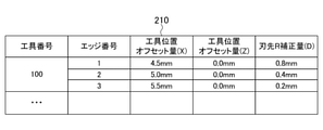
- the tool information memory 200 stores the tool information data 210.
- FIG. 2 is a diagram showing an example of the tool information data 210.
- the tool information data 210 includes, for example, a tool number assigned to each registered multi-edge tool selectable to the machine tool 20, and an edge number assigned to each edge of each multi-edge tool.
- Each edge has a storage area for storing a preset tool position offset amount in the X-axis direction and the Z-axis direction, a cutting edge R correction amount, and the like.
- the tool information data 210 may have a storage area for storing the edge length and the like for each multi-edge tool.
- the tool information data 210 may store a tool number such as "100” assigned to each registered multi-edge tool. Further, in the tool information data 210, edge numbers "1" to “3" are assigned and stored for the multi-edge tool having the tool number "100". This indicates that the multi-edge tool with tool number "100" has three edges.
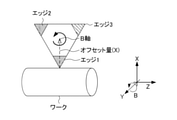
- FIG. 3 is a diagram showing an example of a multi-edge tool having a tool number “100”.
- the multi-edge tool with the tool number "100” has an edge for roughing at the edge number "1", an edge for semi-finishing at the edge number "2", and an edge for finishing at the edge number "3". ..
- the multi-edge tool of FIG. 3 can continuously perform roughing, semi-finishing, and finishing by rotating the B-axis (around the Y-axis).
- the tool information data 210 stores in advance an offset amount in the X-axis direction, an offset amount in the Z-axis direction, and a cutting edge R correction amount for each of the edge numbers "1" to "3".
- the control unit 100 includes a CPU, ROM, RAM, CMOS memory, and the like, which are known to those skilled in the art, which are configured to be able to communicate with each other via a bus.
- the CPU is a processor that controls the numerical control device 10 as a whole.
- the CPU reads out the system program and the application program stored in the ROM via the bus, and controls the entire numerical control device 10 according to the system program and the application program.
- the control unit 100 realizes the functions of the NC command decoding unit 110, the interpolation processing unit 120, the tool correction unit 130, the pulse distribution unit 140, and the tool shape storage / generation unit 150. It is composed of.
- the NC command decoding unit 110 includes a cut amount decoding unit 111, a machining shape generation unit 112, a machining path generation section 113, a tool direction provisional determination section 114, a path coupling determination section 115, a machining path coupling section 116, and a tool direction determination section. It is configured to realize the function of the unit 117. Various data such as temporary calculation data and display data are stored in the RAM.
- the CMOS memory is backed up by a battery (not shown), and is configured as a non-volatile memory whose storage state is maintained even when the power of the numerical control device 10 is turned off.
- the NC command decoding unit 110 acquires, for example, a machining program 30 generated by an external device such as a CAD / CAM device, and analyzes the acquired machining program 30.
- the cut amount decoding unit 111 for example, pre-reads a plurality of blocks included in the machining program 30, and decodes the cut amount at the time of rough machining specified by the NC command in the pre-reading plurality of blocks.
- the machined shape generation unit 112 pre-reads a plurality of blocks included in the machined program 30, and generates the finished shape of the work as the machined shape information from the NC command in the pre-reading plurality of blocks.
- the machining shape generation unit 112 reads, for example, the edge movement direction command (X_Z_) in the edge direction automatic determination mode (for example, G41.9 / G42.9), and the position vector of the tool tip (machining shape). Information). That is, the machined shape generation unit 112 stores all the movement commands that move on the path of the tool as position vectors (machined shape information).
- the machined shape generation unit 112 does not have to be a direct G00 / G01 / G02 / G03 command, but also has a position vector (machined shape information) for a command that internally operates in G00 / G01 / G02 / G03 such as a fixed cycle. May be memorized. Further, the machined shape generation unit 112 may read the block until the edge indexing shaft positioning mode cancel (G40) is read.
- the machining path generation unit 113 generates a rough machining path based on the cut amount at the time of rough machining decoded by the cut amount decoding unit 111 and the finish shape of the work generated by the machining shape generation unit 112. ..
- a roughing processing path when cutting a semi-circular groove as a finishing shape will be illustrated. However, the same applies to the case where an arbitrary shape is cut as the finished shape.
- FIG. 4 is a diagram showing an example of a rough machining path generated by the machining path generation unit 113. As shown in FIG.
- the machining path generation unit 113 cuts a semi-circular groove as a finish shape with respect to the work W, for example, N1 to N11 depending on the depth of cut of the edge for rough machining of the multi-edge tool 40.
- the machining path of is generated as a machining path for rough machining.
- N1 to N11 indicate, for example, the sequence number (block) of the machining program 30.
- the machining paths of N3, N6, and N9 are round-up operation paths, and the machining path of N11 shown by the broken line is an evacuation path after the completion of rough machining.
- the initial position of the edge of the multi-edge tool 40 is at the start point of the machining path of N1 as shown in FIG. 4, and the edge direction of the multi-edge tool 40 at the start of machining is the direction shown in FIG.
- the tool direction temporary determination unit 114 can be used, for example, for geometric information related to the multi-edge tool 40 generated by the tool shape storage / generation unit 150, which will be described later, and for cutting and rounding paths generated by the machining path generation unit 113. Based on this, the edge direction of the multi-edge tool 40, which may omit the round-up operation, is tentatively determined.
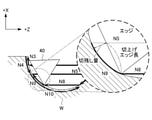
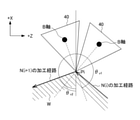
- FIG. 5 is a diagram showing an example when the multi-edge tool 40 is at the end point of the machining path of N2 in the machining path of FIG.
- the circular portion shown by the broken line on the right side of FIG. 5 is an enlarged view of the circular portion shown by the broken line on the left side of FIG.
- the tool direction temporary determination unit 114 for example, when the tip of the edge of the multi-edge tool 40 is at the end point of the machining path of N2, the left edge surface of the multi-edge tool 40 is the work W (that is, N3).
- the edge direction of the multi-edge tool 40 which may omit the round-up operation so as not to interfere with the machining path), is tentatively determined. That is, as shown in the enlarged view on the right side of FIG. 5, the tool direction temporary determination unit 114 includes the multi-edge tool 40 and the work W when the tip of the edge of the multi-edge tool 40 is at the end point of the machining path of N2.
- FIG. 6 is a diagram showing an example when the multi-edge tool 40 is at the end point of the machining path of N5 in the machining path of FIG.
- the tool direction temporary determination unit 114 when the tip of the edge of the multi-edge tool 40 is at the end point of the machining path of N5, the right edge surface of the multi-edge tool 40 is the work W (that is, N1). , N6 machining path), tentatively determine the edge direction of the multi-edge tool 40 that may omit the round-up operation so as not to interfere with it. That is, as shown in FIG.
- FIG. 7 is a diagram showing an example when the multi-edge tool 40 is at the end point of the machining path of N8 in the machining path of FIG.
- the circular portion shown by the broken line on the right side of FIG. 7 is an enlarged view of the circular portion shown by the broken line on the left side of FIG. 7, as in the case of FIG. As in the case of FIG.
- the edge direction of the multi-edge tool 40 which may omit the round-up operation so as not to interfere with the machining path
- the tool direction temporary determination unit 114 includes the multi-edge tool 40 and the work W. Temporarily determine the edge direction of the multi-edge tool 40 so as to take the minimum interference avoidance margin that does not interfere.
- the path coupling determination unit 115 includes the edge direction of the multi-edge tool 40, which may omit the round-up operation provisionally determined by the tool direction temporary determination unit 114, and the cutting and round-up paths generated by the machining path generation unit 113. Therefore, it is determined whether or not to omit the round-up operation in each of the processing paths of N3, N6, and N9. Specifically, in the path coupling determination unit 115, for example, as shown in FIG. 5, the multi-edge tool 40 is tentatively determined at the end point of the machining path of N2 (that is, the start point of the machining path of N3).
- the round-up edge length when facing is calculated and the uncut amount (the longest distance between the machining path of N3 and the left edge surface of the multi-edge tool 40).
- the route coupling determination unit 115 finds that the uncut amount and the rounded edge length are sufficiently small when the calculated uncut amount is equal to or less than the preset threshold value ⁇ and the calculated rounded edge length is equal to or less than the preset threshold ⁇ . It is determined that the round-up operation of the machining path of N3 can be omitted.
- the path coupling determination unit 115 finds that the uncut amount or the rounded edge length is sufficiently large in the processing path of N3. It may be determined that the round-up operation cannot be omitted.
- the multi-edge tool 40 faces in the edge direction tentatively determined at the end point of the machining path of N5 (that is, the start point of the machining path of N6). If so, the round-up edge length and the uncut amount (the longest distance between the machining path of N6 and the right edge surface of the multi-edge tool 40) are calculated. When the calculated uncut amount is equal to or less than the threshold value ⁇ and the calculated rounded edge length is equal to or less than the threshold ⁇ , the path coupling determination unit 115 performs the rounding operation of the N6 machining path because the uncut amount and the rounded edge length are sufficiently small. Judged as optional.
- the path coupling determination unit 115 finds that the uncut amount or the rounded edge length is sufficiently large in the processing path of N6. It may be determined that the round-up operation cannot be omitted.
- the path coupling determination unit 115 faces the multi-edge tool 40 in the edge direction tentatively determined at the end point of the machining path of N8 (that is, the start point of the machining path of N9).
- the round-up edge length in the case and the uncut amount (the longest distance between the machining path of N9 and the left edge surface of the multi-edge tool 40) are calculated.
- the path coupling determination unit 115 performs the rounding operation of the N9 processing path because the uncut amount and the rounded edge length are sufficiently small. Judged as optional.
- the path coupling determination unit 115 finds that the uncut amount or the rounded edge length is sufficiently large in the processing path of N9. It may be determined that the round-up operation cannot be omitted.
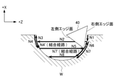
- FIG. 8 is a diagram showing an example of a coupling process of the machining path coupling portion 116 when it is determined that the round-up operation of the machining path of N3 in FIG. 5 can be omitted. Specifically, as shown in FIG.
- FIG. 9 is a diagram showing an example of a coupling process of the machining path coupling portion 116 when it is determined that the round-up operation of the machining path of N6 in FIG. 6 can be omitted.
- the machining path coupling portion 116 moves directly from the end point of the machining path of N5 to the end point of the machining path of N7, omitting the machining path of N6 in the round-up operation, as in the case of FIG.
- FIG. 10 is a diagram showing an example of the result of the coupling process of the machining path coupling portion 116 with respect to the machining path of FIG.
- the uncut amount is larger than the threshold value ⁇ or the rounded edge length. Is larger than the threshold value ⁇ , it is determined by the path coupling determination unit 115 that the round-up operation of the processing path of N9 cannot be omitted, and the case where the processing path of N9 remains as it is is shown.
- the tool direction determination unit 117 is the finish shape of the work W in the rough machining path generated by the machining path generation section 113 or the rough machining path including the new machining path generated by the machining path coupling section 116.
- the edge direction of the multi-edge tool 40 is determined for each change point of the machining shape in which is changed. Specifically, the tool direction determination unit 117 of N (i) at the point (hereinafter, also referred to as “machining shape change point”) at which the machining path of N (i) is switched to the machining path of N (i + 1).
- FIG. 11A is a diagram showing an example in the case where the angle formed between the processing paths at the processing shape change point Pi is less than 180 degrees. As shown in FIG. 11A, in the tool direction determination unit 117, the bisector of the angle formed by the machining path of N (i) and the machining path of N (i + 1) at the machining shape change point Pi is the multi-edge tool 40.
- ⁇ v is the angle (clockwise direction) between the bisector direction and the X-axis direction of the angle formed by the machining path of N (i) and the machining path of N (i + 1) at the machining shape change point Pi. show.
- FIG. 11B is a diagram showing an example when the angle formed between the processing paths at the processing shape change point Pi is 180 degrees or more. As shown in FIG.
- the tool direction determination unit 117 is formed in the vertical direction (broken line) of the cutting surface of each of the machining path of N (i) and the machining path of N (i + 1) at the machining shape change point Pi and the multi-edge tool 40. Determine the edge direction so that it coincides with the center of the edge tip angle.
- ⁇ v1 and ⁇ v2 are the angles (clockwise) between the vertical direction (work side) of the cutting surface and the X-axis direction of the machining path of N (i) and the machining path of N (i + 1) at the machining shape change point Pi. Direction).
- the interpolation processing unit 120 performs interpolation processing on the machining path received from the NC command decoding unit 110, and calculates the command position and the command speed.
- the tool compensating unit 130 provides a position offset amount and a cutting edge R correction amount of the selected multi-edge tool 40, and geometric information of the multi-edge tool 40 generated by the tool shape storage / generation unit 150 described later. Use to calculate the tool compensation amount.
- ⁇ Pulse distribution unit 140 The pulse distribution unit 140 outputs the calculated pulse for each axis movement of the tool correction to each servomotor (not shown) included in the machine tool 20.
- Tool shape storage / generation unit 150 The tool shape storage / generation unit 150 generates geometric information of the multi-edge tool 40 based on the tool information data 210 held in the tool information memory 200.
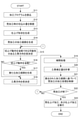
- FIG. 12 is a flowchart illustrating an example of NC command execution processing of the numerical control device 10.
- step S11 the NC command decoding unit 110 reads the machining program 30.
- step S12 the cut amount decoding unit 111 pre-reads a plurality of blocks included in the machining program 30, and decodes the cut amount at the time of rough machining specified by the NC command in the pre-reading plurality of blocks.
- step S13 the machining shape generation unit 112 pre-reads a plurality of blocks included in the machining program 30, and generates a finish shape of the work from NC commands in the pre-reading plurality of blocks.
- step S14 the machining path generation unit 113 generates a rough machining path based on the depth of cut at the time of rough machining decoded in step S12 and the finish shape of the work generated in step S13.
- step S15 the tool direction temporary determination unit 114 determines the geometric information related to the multi-edge tool 40 generated by the tool shape storage / generation unit 150, and cuts and rounds up in the rough machining path generated in step S14. From the path, the edge direction of the multi-edge tool 40, which may omit the round-up operation, is tentatively determined.
- step S16 the route coupling determination unit 115 determines whether or not to omit the round-up operation from the edge direction of the multi-edge tool 40 tentatively determined in step S15 and the cut and round-up paths generated in step S14. do. If the round-up operation is omitted, the process proceeds to step S17. On the other hand, if the round-up operation is not omitted, the process proceeds to step S18.
- step S17 the machining path coupling unit 116 generates a new machining path that directly moves to the end point of the next operation (machining path) of the round-up operation determined to be omitted in step S16.
- step S18 the tool direction determination unit 117 determines the edge direction of the multi-edge tool 40 for each machining shape change point in the rough machining path.
- step S19 the interpolation processing unit 120 performs interpolation processing on the machining path received from the NC command decoding unit 110, and calculates the command position and the command speed.
- the tool compensating unit 130 has a position offset amount (for example, a turning tool) of the selected multi-edge tool 40, a cutting edge R correction amount, and a multi-edge tool generated by the tool shape storage / generation unit 150.
- the tool correction amount is calculated using the geometric information of 40.
- step S21 the numerical control device 10 controls the rough machining process based on the generated machining path.
- step S22 the numerical control device 10 determines whether or not the rough machining process instructed by the machining program 30 has been completed. When the roughing processing is completed, the processing proceeds to step S23. If the roughing process is not completed, the process proceeds to step S15.
- step S23 the numerical control device 10 executes rough finishing (intermediate finishing) and finishing.
- the numerical control device 10 tentatively determines the edge direction of the multi-edge tool 40 from the geometric information related to the multi-edge tool 40 and the cut and round-up paths in the generated rough machining path.
- the numerical control device 10 determines whether or not the round-up operation can be omitted from the tentatively determined edge direction of the multi-edge tool 40 and the generated cut and round-up paths.
- the numerical control device 10 determines that the round-up operation can be omitted, the numerical control device 10 generates a new route that directly moves to the end point of the next operation of the omitted round-up operation.
- the numerical control device 10 can shorten the roughing path and shorten the cycle time in turning. That is, the numerical control device 10 can unify the finishing operation from the cutting by appropriately determining the edge direction of the multi-edge tool 40, and can shorten the cycle time of rough machining.
- the numerical control device 10 is not limited to the above-described embodiment, and includes deformation, improvement, and the like within a range in which the object can be achieved.
- the numerical control device 10 is a device different from the machine tool 20, but is not limited thereto.
- the numerical control device 10 may be included in the machine tool 20.
- the multi-edge tool 40 is used as the tool, but the present invention is not limited to this.
- any tool such as a tool having a swing mechanism that can freely change the relative direction of the tool cutting edge with respect to the work can omit the round-up operation.
- machining path coupling unit 116 omits the round-up operation and directly moves to the end point of the next operation (machining path) of the omitted round-up operation.
- a new machining path has been created, but is not limited to this.
- the machining path coupling portion 116 is next to the omitted round-up operation as shown in FIG.
- the operation of substituting the start point of the operation after the operation and moving directly from the omitted start point of the round-up operation to the start point after the replacement may be referred to as a coupling operation (fast-forward operation).
- fast-forward operation The operation of substituting the start point of the operation after the operation and moving directly from the omitted start point of the round-up operation to the start point after the replacement.
- each function included in the numerical control device 10 in one embodiment can be realized by hardware, software, or a combination thereof.
- what is realized by software means that it is realized by a computer reading and executing a program.
- Non-transitory computer-readable media include various types of tangible recording media (Tangible storage media).
- Examples of non-temporary computer-readable media include magnetic recording media (eg, flexible disks, magnetic tapes, hard disk drives), magneto-optical recording media (eg, magneto-optical disks), CD-ROMs (Read Only Memory), and CD-.
- the program may also be supplied to the computer by various types of temporary computer-readable media (Transition computer readable medium).
- temporary computer readable media include electrical, optical, and electromagnetic waves.
- the temporary computer-readable medium can supply the program to the computer via a wired communication path such as an electric wire and an optical fiber, or a wireless communication path.
- the step of describing the program to be recorded on the recording medium is not only the processing performed in chronological order but also the processing executed in parallel or individually even if it is not necessarily processed in chronological order. Also includes.
- the numerical control device and the control method of the present disclosure can take various embodiments having the following configurations.
- the numerical control device 10 of the present disclosure is a numerical control device that controls a machine tool 20 that can freely change the relative direction of the cutting edge of the tool with respect to the work W, and turns the work W.
- the NC command decoding unit 110 includes an NC command decoding unit 110 that decodes the command of the program 30, and a tool information storage / generation unit 150 that generates and stores geometric information related to the tool.
- the NC command decoding unit 110 is a command of the machining program 30.
- a cut amount decoding unit 111 that decodes the cut amount at the time of rough machining, a machining shape generation unit 112 that generates the finish shape of the work W from a command, and a cut amount at the time of rough machining and the generated work W.
- the direction of the tool is tentatively determined from the machining path generation unit 113 that generates the rough machining path based on the finish shape, the geometric information related to the tool, and the cutting and rounding paths generated by the machining path generation section 113.
- the path coupling determination unit 115 for determining whether or not to omit the round-up operation from the tentatively determined tool direction, the cutting and the round-up path, and the path coupling determination unit 115 omit the round-up operation.
- the round-up operation is omitted and a new path is generated by the machining path coupling section 116 that creates a new path that directly moves to the end point of the next motion of the omitted round-up motion, and a new machining path coupling section 116.
- a tool direction determining unit 117 for determining the direction of the tool at each machining shape change point where the finish shape of the work W changes in the rough machining path including the path. According to this numerical control device 10, it is possible to shorten the machining path and shorten the cycle time in turning.
- the tool direction temporary determination unit 114 temporarily determines the tool direction so that the uncut amount and the tool round-up tool length are minimized, and determines the path connection.
- Unit 115 determines that the round-up operation is omitted when the uncut amount in the tentatively determined direction of the tool is equal to or less than the preset threshold value ⁇ and the round-up tool length of the tool is equal to or less than the preset threshold value ⁇ . May be good.
- the numerical control device 10 can unify the finishing operation from the cutting by appropriately determining the direction of the tool, and can shorten the cycle time of rough machining.
- the machining path coupling unit 116 is the next operation after the round-up operation determined to be omitted by the path coupling determination unit 115, and after the next operation.
- the operation of is a fast-forward operation
- the start point of the operation after the next next operation may be replaced, and the operation of moving directly from the start point of the round-up operation to the start point after the replacement may be generated as a combined operation.
- the numerical control device 10 can fast-forward the tool at once.
- the tool may be a multi-edge tool or a tool having a swing mechanism. By doing so, the numerical control device 10 can exert the same effects as in (1) to (3).
- the control method of the present disclosure is a control method of the machine tool 20 that can freely change the relative direction of the cutting edge of the tool with respect to the work W, which is realized by a computer, and decodes the command of the machining program 30.
- the NC command decoding step is provided with an NC command decoding step and a tool information storage / generation step for generating and storing geometric information related to the tool.
- the NC command decoding step decodes the depth of cut during rough machining from the command of the machining program 30. Roughing path is determined based on the cutting amount decoding step to be performed, the machining shape generation step to generate the finish shape of the work W from the command, the cut amount at the time of rough machining and the finished shape of the generated work W.
- a tool direction tentative determination step for tentatively determining the tool direction and a tentatively determined tool direction from the generated machining path generation step, the geometric information related to the tool, and the cutting and rounding paths generated by the machining path generation step. From the cut and round-up paths, the path coupling determination step that determines whether or not to omit the round-up operation, and if it is determined that the round-up operation is omitted, the round-up operation is omitted and the operation following the omitted round-up operation is performed.
- the machining path joining step that generates a new path that moves directly to the end point and the rough machining path that includes the generated new path, the direction of the tool is determined for each machining shape change point where the finish shape of the work W changes.
- the tool direction determination step is provided. According to this control method, the same effect as in (1) can be obtained.
Landscapes
- Engineering & Computer Science (AREA)
- Physics & Mathematics (AREA)
- Manufacturing & Machinery (AREA)
- Human Computer Interaction (AREA)
- General Physics & Mathematics (AREA)
- Automation & Control Theory (AREA)
- Geometry (AREA)
- Business, Economics & Management (AREA)
- Accounting & Taxation (AREA)
- Development Economics (AREA)
- Economics (AREA)
- General Business, Economics & Management (AREA)
- Computing Systems (AREA)
- Numerical Control (AREA)
- Turning (AREA)
Abstract
Description
まず、本実施形態の概略を説明する。本実施形態では、数値制御装置は、加工プログラムの指令を解読し、解読された加工プログラムの指令に基づいてワークに対する工具の荒加工時の切込み量を解読するとともに、ワークの仕上げ形状を生成する。数値制御装置は、荒加工時の切込み量とワークの仕上げ形状とに基づいて荒加工時の工具の経路を生成する。数値制御装置は、工具の形状を示す幾何学的情報と生成された荒加工時の工具の経路における切込み及び切上げ経路から、切残し量及び工具の切上げ工具長が最小となるように、切上げ動作を省略できる可能性のある工具の方向を仮決定し、仮決定された工具の方向における切残し量が予め設定された第1所定値以下、及び工具の切上げ工具長が予め設定された第1所定値と異なる第2所定値以下の場合、切上げ動作を省略すると判定する。数値制御装置は、省略された切上げ動作の次の動作の終点へ直接移動する新たな経路を生成する。
以上が本実施形態の概略である。
図1は、一実施形態に係る数値制御装置の機能的構成例を示す機能ブロック図である。
数値制御装置10、及び工作機械20は、図示しない接続インタフェースを介して、互いに直接接続されてもよい。なお、数値制御装置10、及び工作機械20は、LAN(Local Area Network)やインターネット等の図示しないネットワークを介して相互に接続されていてもよい。この場合、数値制御装置10、及び工作機械20は、かかる接続によって相互に通信を行うための図示しない通信部を備えている。
図1に示すように、数値制御装置10は、制御部100、及び工具情報メモリ200を有する。また、制御部100は、NC指令解読部110、補間処理部120、工具補正部130、パルス分配部140、及び工具形状記憶・生成部150を有する。さらに、NC指令解読部110は、切込み量解読部111、加工形状生成部112、加工経路生成部113、工具方向仮決定部114、経路結合判定部115、加工経路結合部116、及び工具方向決定部117を有する。
工具情報メモリ200は、SSD(Solid State Drive)やHDD(Hard Disk Drive)等の記憶部である。工具情報メモリ200は、工具情報データ210を記憶する。
図2に示すように、工具情報データ210は、例えば、工作機械20に選択可能な登録されたマルチエッジ工具毎に付与される工具番号、マルチエッジ工具毎の各エッジに付与されるエッジ番号、エッジ毎に予め設定されたX軸方向とZ軸方向との工具位置オフセット量、及び刃先R補正量等を格納する格納領域を有する。
なお、工具情報データ210は、マルチエッジ工具毎のエッジ長等を格納する格納領域を有してもよい。
また、工具情報データ210では、工具番号「100」のマルチエッジ工具に対してエッジ番号「1」から「3」が付与され格納されている。このことから、工具番号「100」のマルチエッジ工具は、3つのエッジを有することを示す。
制御部100は、CPU、ROM、RAM、CMOSメモリ等を有し、これらはバスを介して相互に通信可能に構成される、当業者にとって公知のものである。
CPUは数値制御装置10を全体的に制御するプロセッサである。CPUは、ROMに格納されたシステムプログラム及びアプリケーションプログラムを、バスを介して読み出し、前記システムプログラム及びアプリケーションプログラムに従って数値制御装置10全体を制御する。これにより、図1に示すように、制御部100は、NC指令解読部110、補間処理部120、工具補正部130、パルス分配部140、及び工具形状記憶・生成部150の機能を実現するように構成される。また、NC指令解読部110は、切込み量解読部111、加工形状生成部112、加工経路生成部113、工具方向仮決定部114、経路結合判定部115、加工経路結合部116、及び工具方向決定部117の機能を実現するように構成される。RAMには一時的な計算データや表示データ等の各種データが格納される。CMOSメモリは図示しないバッテリでバックアップされ、数値制御装置10の電源がオフされても記憶状態が保持される不揮発性メモリとして構成される。
NC指令解読部110は、例えば、CAD/CAM装置等の外部装置により生成された加工プログラム30を取得し、取得された加工プログラム30を解析する。
切込み量解読部111は、例えば、加工プログラム30に含まれる複数のブロックを先読みし、先読みした複数のブロックにおけるNC指令から指定された荒加工時の切込み量を解読する。
加工形状生成部112は、例えば、加工プログラム30に含まれる複数のブロックを先読みし、先読みした複数のブロックにおけるNC指令からワークの仕上げ形状を、加工形状情報として生成する。
具体的には、加工形状生成部112は、例えば、エッジ方向自動決定モード(例えば、G41.9/G42.9)中のエッジ移動方向指令(X_Z_)を読み取り、工具先端の位置ベクトル(加工形状情報)として記憶する。すなわち、加工形状生成部112は、工具の経路上を移動する移動指令を位置ベクトル(加工形状情報)として全て記憶する。
なお、加工形状生成部112は、直接のG00/G01/G02/G03指令でなくても、固定サイクル等内部的にG00/G01/G02/G03で動作する指令についても位置ベクトル(加工形状情報)を記憶するようにしてもよい。また、加工形状生成部112は、エッジ割り出し軸位置決めモードキャンセル(G40)を読み取るまでブロックの読み込みを行なうようにしてもよい。
加工経路生成部113は、切込み量解読部111により解読された荒加工時の切込み量と、加工形状生成部112により生成されたワークの仕上げ形状と、に基づいて荒加工の加工経路を生成する。
なお、以下の説明では、仕上げ形状として半円形の溝を切削する場合の荒加工の加工経路を例示する。しかしながら、仕上げ形状として任意の形状を切削する場合についても同様である。
図4は、加工経路生成部113により生成された荒加工の加工経路の一例を示す図である。
図4に示すように、加工経路生成部113は、例えば、ワークWに対して仕上げ形状として半円形の溝を切削する場合、マルチエッジ工具40の荒加工用のエッジの切込み量によりN1~N11の加工経路を荒加工の加工経路として生成する。なお、N1~N11は、例えば、加工プログラム30のシーケンス番号(ブロック)を示す。また、N3、N6、N9の加工経路は切上げ動作の経路であり、破線で示すN11の加工経路は荒加工終了後の退避経路である。また、マルチエッジ工具40のエッジの初期位置は、図4に示すように、N1の加工経路の始点にあり、加工開始時のマルチエッジ工具40のエッジ方向は、図4に示す方向とする。
工具方向仮決定部114は、例えば、後述する工具形状記憶・生成部150により生成されるマルチエッジ工具40に係る幾何学的情報と、加工経路生成部113により生成された切込み及び切上げ経路とに基づいて、切上げ動作を省略できる可能性のあるマルチエッジ工具40のエッジ方向を仮決定する。
図5は、図4の加工経路においてマルチエッジ工具40がN2の加工経路の終点にあるときの一例を示す図である。なお、図5の右側の破線で示す円形部分は、図5の左側の破線で示す円形部分を拡大した拡大図である。
具体的には、工具方向仮決定部114は、例えば、N2の加工経路の終点にマルチエッジ工具40のエッジの先端があるとき、マルチエッジ工具40の左側エッジ面がワークW(すなわち、N3の加工経路)と干渉しないような、切上げ動作を省略できる可能性のあるマルチエッジ工具40のエッジ方向を仮決定する。すなわち、図5の右側の拡大図が示すように、工具方向仮決定部114は、N2の加工経路の終点にマルチエッジ工具40のエッジの先端があるときに、マルチエッジ工具40とワークWとが干渉しない最小のマージン(以下、「干渉回避マージン」ともいう)を取るように、マルチエッジ工具40のエッジ方向を仮決定する。
工具方向仮決定部114は、図5の場合と同様に、N5の加工経路の終点にマルチエッジ工具40のエッジの先端があるとき、マルチエッジ工具40の右側エッジ面がワークW(すなわち、N1、N6の加工経路)と干渉しないような、切上げ動作を省略できる可能性のあるマルチエッジ工具40のエッジ方向を仮決定する。すなわち、図6が示すように、工具方向仮決定部114は、マルチエッジ工具40とワークWとが干渉しない最小の干渉回避マージンを取るように、切上げ動作を省略できる可能性のあるマルチエッジ工具40のエッジ方向を仮決定する。
図7は、図4の加工経路においてマルチエッジ工具40がN8の加工経路の終点にあるときの一例を示す図である。なお、図7の右側の破線で示す円形部分は、図5の場合と同様に、図7の左側の破線で示す円形部分を拡大した拡大図である。
工具方向仮決定部114は、図5の場合と同様に、N8の加工経路の終点にマルチエッジ工具40のエッジの先端があるとき、マルチエッジ工具40の左側エッジ面がワークW(すなわち、N3、N4、N9の加工経路)と干渉しないような、切上げ動作を省略できる可能性のあるマルチエッジ工具40のエッジ方向を仮決定する。すなわち、図7の右側の拡大図が示すように、工具方向仮決定部114は、N8の加工経路の終点にマルチエッジ工具40のエッジの先端があるときに、マルチエッジ工具40とワークWとが干渉しない最小の干渉回避マージンを取るように、マルチエッジ工具40のエッジ方向を仮決定する。
経路結合判定部115は、工具方向仮決定部114により仮決定された切上げ動作を省略できる可能性のあるマルチエッジ工具40のエッジ方向と、加工経路生成部113により生成された切込み及び切上げ経路とから、N3、N6、N9の加工経路それぞれにおける切上げ動作を省略するか否かを判定する。
具体的には、経路結合判定部115は、例えば、図5に示すように、N2の加工経路の終点(すなわち、N3の加工経路の始点)において仮決定されたエッジ方向にマルチエッジ工具40が向いている場合の切上げエッジ長と、切残し量(N3の加工経路とマルチエッジ工具40の左側エッジ面との間の最長距離)とを算出する。経路結合判定部115は、算出した切残し量が予め設定された閾値α以下、及び算出した切上げエッジ長が予め設定された閾値β以下の場合、切残し量及び切上げエッジ長が十分小さいことからN3の加工経路の切上げ動作を省略可能と判定する。一方、経路結合判定部115は、算出した切残し量が閾値αより大きい、又は算出した切上げエッジ長が閾値βより大きい場合、切残し量又は切上げエッジ長が十分大きいことからN3の加工経路の切上げ動作を省略不可と判定するようにしてもよい。
加工経路結合部116は、経路結合判定部115により切上げ動作を省略すると判定された場合、切上げ動作を省略し、省略された切上げ動作の次の動作(加工経路)の終点へ直接移動する新たな加工経路を生成する。
図8は、図5のN3の加工経路の切上げ動作が省略可能と判定された場合の加工経路結合部116の結合処理の一例を示す図である。
具体的には、加工経路結合部116は、例えば、図8に示すように、切上げ動作のN3の加工経路を省略して、N2の加工経路の終点からN4の加工経路の終点へ直接移動する新たなN4’の加工経路を生成する。
図9は、図6のN6の加工経路の切上げ動作が省略可能と判定された場合の加工経路結合部116の結合処理の一例を示す図である。
図9に示すように、加工経路結合部116は、図8の場合と同様に、切上げ動作のN6の加工経路を省略して、N5の加工経路の終点からN7の加工経路の終点へ直接移動する新たなN7’の加工経路を生成する。
図10は、図4の加工経路に対する加工経路結合部116の結合処理の結果の一例を示す図である。なお、図10の加工経路では、図7に示すN8の加工経路の終点において仮決定されたエッジ方向にマルチエッジ工具40が向いている場合の切残し量が閾値αより大きい、又は切上げエッジ長が閾値βより大きいため、N9の加工経路の切上げ動作が省略不可と経路結合判定部115により判定され、N9の加工経路がそのまま残っている場合を示す。
工具方向決定部117は、加工経路生成部113により生成された荒加工の加工経路、又は加工経路結合部116により生成された新たな加工経路を含む荒加工の加工経路において、ワークWの仕上げ形状が変化する加工形状変化点毎にマルチエッジ工具40のエッジ方向を決定する。
具体的には、工具方向決定部117は、N(i)の加工経路からN(i+1)の加工経路に切り換わる点(以下、「加工形状変化点」ともいう)PiにおけるN(i)の加工経路とN(i+1)の加工経路とのなす角度が180度未満の場合、当該角度の中心線とマルチエッジ工具40のエッジ先端点の中心線とが一致する角度をエッジ方向(エッジ割り出し軸の位置決め角度)と決定する。なお、iは1から10の整数である。
図11Aは、加工形状変化点Piにおける加工経路間のなす角度が180度未満の場合の一例を示す図である。
図11Aに示すように、工具方向決定部117は、加工形状変化点PiにおけるN(i)の加工経路とN(i+1)の加工経路とのなす角度の2等分線がマルチエッジ工具40のエッジ先端角の中心と一致するようにエッジ方向を決定する。ここで、θvは加工形状変化点PiにおけるN(i)の加工経路とN(i+1)の加工経路とがなす角度の2等分線方向とX軸方向との角度(時計回り方向)を示す。
図11Bは、加工形状変化点Piにおける加工経路間のなす角度が180度以上の場合の一例を示す図である。
図11Bに示すように、工具方向決定部117は、加工形状変化点PiにおけるN(i)の加工経路及びN(i+1)の加工経路それぞれの切削面垂直方向(破線)とマルチエッジ工具40のエッジ先端角の中心とが一致するようにエッジ方向を決定する。ここで、θv1、θv2は加工形状変化点PiにおけるN(i)の加工経路及びN(i+1)の加工経路それぞれの切削面垂直方向(ワーク側)とX軸方向との角度(時計回り方向)を示す。
補間処理部120は、NC指令解読部110から受信した加工経路に対して補間処理を行い、指令位置や指令速度を算出する。
工具補正部130は、選択されたマルチエッジ工具40の位置オフセット量、及び刃先R補正量と、後述する工具形状記憶・生成部150により生成されたマルチエッジ工具40の幾何学的情報と、を用いて、工具補正量を計算する。
パルス分配部140は、計算された工具補正の各軸移動分のパルスが工作機械20に含まれる各サーボモータ(図示しない)に出力する。
工具形状記憶・生成部150は、工具情報メモリ200に保持された工具情報データ210に基づいてマルチエッジ工具40の幾何学的情報を生成する。
次に、マルチエッジ工具40を用い旋削加工する加工プログラム30に基づいて荒加工を行う場合の、数値制御装置10のNC指令実行処理に係る動作の一例について説明する。
図12は、数値制御装置10のNC指令実行処理の一例について説明するフローチャートである。
これにより、数値制御装置10は、旋削加工において荒加工経路を短縮し、サイクルタイムを短縮することができる。すなわち、数値制御装置10は、マルチエッジ工具40のエッジ方向を適切に決めることで、切込みから仕上げ動作を一本化でき、荒加工のサイクルタイムを短縮することができる。
上述の実施形態では、数値制御装置10は、工作機械20と異なる装置としたが、これに限定されない。例えば、数値制御装置10は、工作機械20に含まれてもよい。
また例えば、上述の実施形態では、工具としてマルチエッジ工具40が用いられたが、これに限定されない。例えば、図13に示すように、首振り機構を有した工具等、ワークに対する工具刃先の相対的な向きを自由に変えることができる工具であれば、切上げ動作の省略は可能である。
また例えば、加工経路結合部116は、経路結合判定部115により切上げ動作を省略すると判定された場合、切上げ動作を省略し、省略された切上げ動作の次の動作(加工経路)の終点へ直接移動する新たな加工経路を生成したが、これに限定されない。例えば、省略する切上げ動作の次の動作、及び次の次の動作以降の動作が早送り動作の場合、加工経路結合部116は、図14に示すように、省略された切上げ動作の次の次の動作以降の動作の始点をすり替え、省略された切上げ動作の始点から直接すり替え後の始点へ移動する動作を結合動作(早送り動作)としてもよい。
そうすることで、数値制御装置10は、工具を一気に早送りすることができる。
この数値制御装置10によれば、旋削加工において加工経路を短縮し、サイクルタイムを短縮することができる。
そうすることで、数値制御装置10は、工具の方向を適切に決めることで、切込みから仕上げ動作を一本化でき、荒加工のサイクルタイムを短縮することができる。
そうすることで、数値制御装置10は、工具を一気に早送りすることができる。
そうすることで、数値制御装置10は、(1)から(3)と同様の効果を奏することができる。
この制御方法によれば、(1)と同様の効果を奏することができる。
100 制御装置
110 NC指令解読部
111 切込み量解読部
112 加工形状生成部
113 加工経路生成部
114 工具方向仮決定部
115 経路結合判定部
116 加工経路結合部
117 工具方向決定部
120 補間処理部
130 工具補正部
140 パルス分配部
150 工具形状記憶・生成部
200 工具情報メモリ
210 工具情報データ
20 工作機械
30 加工プログラム
Claims (5)
- ワークに対する工具の刃先の相対的な方向を自由に変更可能な工作機械を制御し、前記ワークを旋削加工する数値制御装置であって、
加工プログラムの指令を解読するNC指令解読部と、
前記工具に係る幾何学的情報を生成し記憶する工具情報記憶・生成部と、を備え、
前記NC指令解読部は、
前記加工プログラムの指令から荒加工時の切込み量を解読する切込み量解読部と、
前記指令から前記ワークの仕上げ形状を生成する加工形状生成部と、
解読された前記荒加工時の切込み量と生成された前記ワークの仕上げ形状とに基づいて荒加工の経路を生成する加工経路生成部と、
前記工具に係る幾何学的情報と前記加工経路生成部によって生成された切込み及び切上げ経路から、前記工具の方向を仮決定する工具方向仮決定部と、
仮決定した前記工具の方向と前記切込み及び切上げ経路から、切上げ動作を省略するか否かを判定する経路結合判定部と、
前記経路結合判定部により前記切上げ動作を省略すると判定された場合、前記切上げ動作を省略し、省略された前記切上げ動作の次の動作の終点へ直接移動する新たな経路を生成する加工経路結合部と、
前記加工経路結合部により生成された前記新たな経路を含む前記荒加工の経路において、前記ワークの仕上げ形状が変化する加工形状変化点毎に前記工具の方向を決定する工具方向決定部と、を備える
数値制御装置。 - 前記工具方向仮決定部は、切残し量及び前記工具の切上げ工具長が最小となるように、前記工具の方向を仮決定し、
前記経路結合判定部は、仮決定された前記工具の方向における前記切残し量が予め設定された第1所定値以下、及び前記工具の切上げ工具長が予め設定された前記第1所定値と異なる第2所定値以下の場合、前記切上げ動作を省略すると判定する
請求項1に記載の数値制御装置。 - 前記加工経路結合部は、前記経路結合判定部により省略すると判定された前記切上げ動作の次の動作及び次の次の動作以降の動作が早送り動作の場合、前記次の次の動作以降の動作の始点をすり替え、前記切上げ動作の始点から直接すり替え後の始点へ移動する動作を結合動作として生成する、請求項1又は請求項2に記載の数値制御装置。
- 前記工具は、マルチエッジ工具又は首振り機構を有する工具である、請求項1から請求項3のいずれか1項に記載の数値制御装置。
- コンピュータにより実現される、ワークに対する工具の刃先の相対的な方向を自由に変更可能な工作機械の制御方法であって、
加工プログラムの指令を解読するNC指令解読ステップと、
前記工具に係る幾何学的情報を生成し記憶する工具情報記憶・生成ステップと、を備え、
前記NC指令解読ステップは、
前記加工プログラムの指令から荒加工時の切込み量を解読する切込み量解読ステップと、
前記指令から前記ワークの仕上げ形状を生成する加工形状生成ステップと、
解読された前記荒加工時の切込み量と生成された前記ワークの仕上げ形状とに基づいて荒加工の経路を生成する加工経路生成ステップと、
前記工具に係る幾何学的情報と前記加工経路生成ステップによって生成された切込み及び切上げ経路から、前記工具の方向を仮決定する工具方向仮決定ステップと、
仮決定した前記工具の方向と前記切込み及び切上げ経路から、切上げ動作を省略するか否かを判定する経路結合判定ステップと、
前記切上げ動作を省略すると判定された場合、前記切上げ動作を省略し、省略された前記切上げ動作の次の動作の終点へ直接移動する新たな経路を生成する加工経路結合ステップと、
生成された前記新たな経路を含む前記荒加工の経路において、前記ワークの仕上げ形状が変化する加工形状変化点毎に前記工具の方向を決定する工具方向決定ステップと、を備える
制御方法。
Priority Applications (4)
| Application Number | Priority Date | Filing Date | Title |
|---|---|---|---|
| CN202180060111.XA CN116133778B (zh) | 2020-07-30 | 2021-07-26 | 数值控制装置以及控制方法 |
| DE112021004016.2T DE112021004016T5 (de) | 2020-07-30 | 2021-07-26 | Numerisches Steuergerät und Steuerverfahren |
| US18/014,374 US12541188B2 (en) | 2020-07-30 | 2021-07-26 | Numerical controller and control method |
| JP2022540281A JP7436678B2 (ja) | 2020-07-30 | 2021-07-26 | 数値制御装置、及び制御方法 |
Applications Claiming Priority (2)
| Application Number | Priority Date | Filing Date | Title |
|---|---|---|---|
| JP2020129217 | 2020-07-30 | ||
| JP2020-129217 | 2020-07-30 |
Publications (1)
| Publication Number | Publication Date |
|---|---|
| WO2022024975A1 true WO2022024975A1 (ja) | 2022-02-03 |
Family
ID=80036352
Family Applications (1)
| Application Number | Title | Priority Date | Filing Date |
|---|---|---|---|
| PCT/JP2021/027494 Ceased WO2022024975A1 (ja) | 2020-07-30 | 2021-07-26 | 数値制御装置、及び制御方法 |
Country Status (5)
| Country | Link |
|---|---|
| US (1) | US12541188B2 (ja) |
| JP (1) | JP7436678B2 (ja) |
| CN (1) | CN116133778B (ja) |
| DE (1) | DE112021004016T5 (ja) |
| WO (1) | WO2022024975A1 (ja) |
Families Citing this family (2)
| Publication number | Priority date | Publication date | Assignee | Title |
|---|---|---|---|---|
| EP4380745A4 (en) * | 2021-08-04 | 2025-08-27 | Celeritive Tech Inc | METHODS FOR PREVENTING NOTCH FORMATION IN, AND/OR EXTENDING THE USEFUL LIFE OF, CUTTING TOOLS FOR TURNING, AND RELATED SYSTEMS |
| CN117399656B (zh) * | 2023-11-06 | 2026-02-13 | 中船华南船舶机械广州有限公司 | 一种绞车滚筒用绳槽加工方法 |
Citations (2)
| Publication number | Priority date | Publication date | Assignee | Title |
|---|---|---|---|---|
| WO2016009502A1 (ja) * | 2014-07-16 | 2016-01-21 | ヤマザキマザック 株式会社 | 旋削加工制御装置、および旋削加工支援プログラム |
| JP2020027410A (ja) * | 2018-08-10 | 2020-02-20 | ファナック株式会社 | 加工経路生成装置及び数値制御装置 |
Family Cites Families (13)
| Publication number | Priority date | Publication date | Assignee | Title |
|---|---|---|---|---|
| JPS61168457A (ja) * | 1985-01-23 | 1986-07-30 | Hitachi Ltd | 数値制御加工方式 |
| JP2001337707A (ja) | 2000-05-29 | 2001-12-07 | Daido Steel Co Ltd | 旋削ncデータ自動作成方法およびその前処理方法 |
| JP4489323B2 (ja) * | 2001-05-28 | 2010-06-23 | 東芝機械株式会社 | 数値制御装置 |
| JP2005288563A (ja) * | 2004-03-31 | 2005-10-20 | Yamazaki Mazak Corp | 加工プログラム作成方法、及び加工プログラム作成装置 |
| CN202239684U (zh) | 2011-09-08 | 2012-05-30 | 江阴市长龄机械制造有限公司 | 螺旋槽刀 |
| JP6297283B2 (ja) * | 2013-09-06 | 2018-03-20 | 中村留精密工業株式会社 | 工作機械の工具オフセット値の自動設定装置及び自動設定方法 |
| JP5902753B2 (ja) | 2014-05-28 | 2016-04-13 | ファナック株式会社 | 切上げ・切込み運動または円運動挿入機能を有する数値制御装置 |
| JP2016085650A (ja) | 2014-10-28 | 2016-05-19 | ブラザー工業株式会社 | 数値制御装置と制御方法 |
| JP5936781B1 (ja) * | 2014-10-29 | 2016-06-22 | 三菱電機株式会社 | 数値制御装置、nc加工装置、nc加工方法およびシミュレーション装置 |
| JP6691851B2 (ja) * | 2016-08-23 | 2020-05-13 | 三菱重工業株式会社 | 素材形状の決定方法、加工方法、素材形状の決定システム及び素材形状の決定プログラム |
| JP6719331B2 (ja) * | 2016-08-23 | 2020-07-08 | 三菱重工業株式会社 | 数値制御プログラムの生成方法、要素作成方法、生成システム及び生成プログラム |
| JP2019149047A (ja) * | 2018-02-27 | 2019-09-05 | ファナック株式会社 | 制御装置 |
| JP7090018B2 (ja) | 2018-11-14 | 2022-06-23 | 株式会社ツガミ | 工作機械 |
-
2021
- 2021-07-26 WO PCT/JP2021/027494 patent/WO2022024975A1/ja not_active Ceased
- 2021-07-26 JP JP2022540281A patent/JP7436678B2/ja active Active
- 2021-07-26 DE DE112021004016.2T patent/DE112021004016T5/de active Pending
- 2021-07-26 CN CN202180060111.XA patent/CN116133778B/zh active Active
- 2021-07-26 US US18/014,374 patent/US12541188B2/en active Active
Patent Citations (2)
| Publication number | Priority date | Publication date | Assignee | Title |
|---|---|---|---|---|
| WO2016009502A1 (ja) * | 2014-07-16 | 2016-01-21 | ヤマザキマザック 株式会社 | 旋削加工制御装置、および旋削加工支援プログラム |
| JP2020027410A (ja) * | 2018-08-10 | 2020-02-20 | ファナック株式会社 | 加工経路生成装置及び数値制御装置 |
Also Published As
| Publication number | Publication date |
|---|---|
| JP7436678B2 (ja) | 2024-02-22 |
| CN116133778B (zh) | 2025-08-05 |
| DE112021004016T5 (de) | 2023-07-20 |
| JPWO2022024975A1 (ja) | 2022-02-03 |
| US12541188B2 (en) | 2026-02-03 |
| US20230305521A1 (en) | 2023-09-28 |
| CN116133778A (zh) | 2023-05-16 |
Similar Documents
| Publication | Publication Date | Title |
|---|---|---|
| WO2022024975A1 (ja) | 数値制御装置、及び制御方法 | |
| US10324444B2 (en) | Numerical controller including tool retracting function for avoidance of interference | |
| JP5908552B1 (ja) | 工作機械の制御装置 | |
| JP5886656B2 (ja) | 数値制御装置 | |
| US10444728B2 (en) | Numerical controller performing positioning for avoiding interference with workpiece | |
| JP7112375B2 (ja) | Ncプログラム生成システム及びncプログラム生成方法 | |
| JP7787196B2 (ja) | 数値制御装置 | |
| JP6770018B2 (ja) | 設定装置及び設定プログラム | |
| JP7032615B1 (ja) | 数値制御装置、及び制御方法 | |
| CN108334042B (zh) | 数值控制装置 | |
| JPS6365469B2 (ja) | ||
| US11720083B2 (en) | Numerical control device | |
| US12498696B2 (en) | Numerical controller and control method to control a multi-edge tool | |
| US11320800B2 (en) | Optimization device | |
| JP7691554B2 (ja) | 情報処理装置、及び情報処理方法 | |
| US11215969B2 (en) | Numerical control device and machine tool | |
| JP7832227B2 (ja) | 数値制御装置 | |
| JPWO2022059595A5 (ja) | ||
| JP6923736B2 (ja) | 数値制御装置 | |
| JPH07253810A (ja) | 数値制御加工装置 | |
| JPH01314307A (ja) | 数値制御装置 | |
| JP2021058992A (ja) | 数値制御装置 |
Legal Events
| Date | Code | Title | Description |
|---|---|---|---|
| 121 | Ep: the epo has been informed by wipo that ep was designated in this application |
Ref document number: 21851467 Country of ref document: EP Kind code of ref document: A1 |
|
| ENP | Entry into the national phase |
Ref document number: 2022540281 Country of ref document: JP Kind code of ref document: A |
|
| 122 | Ep: pct application non-entry in european phase |
Ref document number: 21851467 Country of ref document: EP Kind code of ref document: A1 |
|
| WWG | Wipo information: grant in national office |
Ref document number: 202180060111.X Country of ref document: CN |
|
| WWG | Wipo information: grant in national office |
Ref document number: 18014374 Country of ref document: US |