WO2022024696A1 - エアバッグモジュールおよびそれを備えた車両 - Google Patents
エアバッグモジュールおよびそれを備えた車両 Download PDFInfo
- Publication number
- WO2022024696A1 WO2022024696A1 PCT/JP2021/025611 JP2021025611W WO2022024696A1 WO 2022024696 A1 WO2022024696 A1 WO 2022024696A1 JP 2021025611 W JP2021025611 W JP 2021025611W WO 2022024696 A1 WO2022024696 A1 WO 2022024696A1
- Authority
- WO
- WIPO (PCT)
- Prior art keywords
- airbag
- vehicle
- airbag module
- cover
- deployed
- Prior art date
- Legal status (The legal status is an assumption and is not a legal conclusion. Google has not performed a legal analysis and makes no representation as to the accuracy of the status listed.)
- Ceased
Links
Images




Classifications
-
- B—PERFORMING OPERATIONS; TRANSPORTING
- B60—VEHICLES IN GENERAL
- B60R—VEHICLES, VEHICLE FITTINGS, OR VEHICLE PARTS, NOT OTHERWISE PROVIDED FOR
- B60R21/00—Arrangements or fittings on vehicles for protecting or preventing injuries to occupants or pedestrians in case of accidents or other traffic risks
- B60R21/34—Protecting non-occupants of a vehicle, e.g. pedestrians
- B60R21/36—Protecting non-occupants of a vehicle, e.g. pedestrians using airbags
Definitions
- This disclosure relates to an airbag module and a vehicle equipped with it.
- Patent Document 1 describes a gas bag that is deployed from the bumper at the front of the vehicle to the outside of the vehicle to protect pedestrians. When deployed toward the road surface, the gas bag comes into contact with the pedestrian's legs at a short distance from the road surface. Further, in the region facing the road surface in the deployed state of the gas bag, an outer layer having high resistance to a load due to friction and a separate wearing body are attached to the inner layer.
- the airbag deployed on the outside of the vehicle is configured to form a gap with the ground after deployment, when the airbag is deployed, a part of it comes into contact with the ground due to the momentum during deployment. There is a possibility of doing. When the airbag comes into contact with the ground, it may be damaged due to a load due to friction with the ground.
- the present disclosure has been made in view of the above circumstances, and an object of the present disclosure is to provide a technique capable of preventing damage to an airbag while suppressing an increase in manufacturing cost.
- a cover is provided so that the airbag is integrated with the airbag and falls off from the main body when the airbag is deployed.
- the present disclosure is an airbag module attached to the front or rear of a vehicle, which is arranged in the vehicle and has a main body portion having a storage space for accommodating the airbag, and the storage space and the vehicle.
- An opening that communicates with the outside of the bottom surface and is arranged so as to face the ground, and the airbag housed in the storage space from the opening when gas is supplied.
- the airbag deployed between the bottom surface of the vehicle and the ground, and a cover covering the opening and fixing at least a part of the airbag housed in the storage space, wherein the airbag is deployed. It is provided with a cover configured to be integrated with the airbag and fall off from the main body when the airbag is used.
- the airbag module having such a configuration it is not necessary to provide a cover over a wide range of the airbag, and it can be manufactured at low cost by using a simple configuration. Therefore, the airbag module having the above configuration can prevent the airbag from being damaged while suppressing an increase in production cost. Further, since the airbag module having the above configuration can prevent the airbag from being damaged during deployment, it is possible to prevent pedestrians from being pinched between the vehicle and the ground.
- the cover may be fixed to the airbag so as to cover at least a part of the deployed airbag that is closest to the ground. According to the airbag module having such a configuration, only the portion of the airbag closest to the ground when the airbag is deployed can be covered with the cover, so that the whole can be compactly configured.
- the cover is integrally configured with the main body portion, and the main body portion may be formed with a fragile portion for partitioning the cover.
- the fragile portion may be formed in a straight line or a curved line, and may be formed in a continuous or dotted line shape.
- the airbag module is attached to the front of the vehicle, and when the airbag is deployed, the airbag module extends from the position of the main body toward the front of the vehicle, and the front deployment portion and the main body portion. It has a rear deployment portion extending from the position toward the rear of the vehicle, and the length from the position of the main body portion to the tip of the front deployment portion is from the position to the tip of the rear deployment portion. It may be shorter than the length. According to the airbag module having such a configuration, the amount of the airbag deployed forward is smaller than the amount of rearward deployment, so that the gap under the vehicle is filled and the vehicle is moving forward. Even if the cover touches the ground, the possibility that the front deployment portion is caught in the rear of the vehicle can be reduced.
- the airbag module is arranged at a position corresponding to the prime mover of the vehicle, and the airbag may be deployed including the position corresponding to the prime mover. According to the airbag module having such a configuration, it is possible to prevent the prime mover of the vehicle from being submerged in the event of flood damage or the like.
- the present disclosure can also be viewed from the side of the vehicle.
- the present disclosure may be a vehicle equipped with the airbag module described in any of the above.
- FIG. It is a figure which shows the vehicle which mounted the airbag module which concerns on Embodiment 1. It is a figure which shows the airbag module which concerns on Embodiment 1.
- FIG. It is a figure which shows the state which the airbag of the airbag module which concerns on Embodiment 1 is deployed. It is a figure which shows the state which the airbag of the airbag module which concerns on the modification of Embodiment 1 is deployed. It is a figure which shows the state which the airbag of the airbag module which concerns on Embodiment 2 is deployed. It is a figure which shows the state which the airbag of the airbag module which concerns on Embodiment 3 is deployed.
- the airbag module according to the first embodiment will be described.
- the airbag module according to the present embodiment is mounted on a vehicle such as an automobile and is exemplified as a device for protecting a pedestrian.
- FIG. 1 is a view when the vehicle 100 on which the airbag module 1 according to the first embodiment is mounted is viewed from the right side.
- the arrow A indicates the traveling direction when the vehicle 100 moves forward.
- the airbag module 1 according to the present embodiment is attached to the front of the vehicle 100, and deploys the airbag between the bottom surface 101 of the vehicle 100 and the ground G. As a result, the airbag module 1 protects the pedestrian by preventing the pedestrian from being pinched between the vehicle 100 and the ground G.
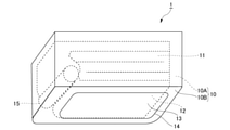
- FIG. 2 is an external perspective view of the airbag module 1 according to the present embodiment.
- the airbag module 1 includes a main body 10 and an airbag 11 arranged inside the vehicle 100 shown in FIG. 1.
- the main body 10 is formed in a box shape and has a storage space 10A for accommodating the airbag 11 inside.
- a cloth airbag 11 is folded and accommodated in the storage space 10A.
- the main body portion 10 is made of metal except for the bottom surface portion 10B made of resin, and the entire main body portion 10 is integrally formed by a known method such as caulking or fixing the resin bottom surface portion 10B with a screw at the metal portion. Has been done.
- the main body 10 may be entirely made of metal or resin.
- the airbag module 1 is arranged in the vehicle 100 so that the bottom surface portion 10B of the main body portion 10 faces the bottom surface side of the vehicle 100.
- the airbag module 1 includes an opening 12 arranged in the bottom surface portion 10B so as to face the ground G.
- the opening 12 communicates the storage space 10A with the outside of the bottom surface 101 of the vehicle 100.
- the airbag 11 expands from the opening 12 between the bottom surface 101 of the vehicle 100 and the ground G by being supplied with gas.
- the airbag module 1 includes a cover 13 that covers the opening 12 in the non-operating state.
- the cover 13 is more resistant to frictional loads than the cloth airbag 11.
- the cover 13 is integrally configured with the main body portion 10 or the bottom surface portion 10B, and the bottom surface portion 10B is formed with a fragile portion 14 for partitioning the cover 13.
- the airbag 11 pushes down the cover 13 to apply a load to the fragile portion 14, so that the fragile portion 14 is destroyed and the cover 13 falls off from the bottom surface portion 10B.
- the opening 12 is opened.
- the fragile portion 14 is formed to open the opening portion 12 when the airbag 11 is deployed.
- the fragile portion 14 is a portion that breaks preferentially over other portions when a predetermined load is applied, and is thinner or stronger than the surroundings (for example, the cover 13 or the bottom portion 10B). It is a low part.
- the fragile portion 14 may be continuously formed on a straight line, or may be formed in a linear dotted line.
- the fragile portion 14 can be easily formed on the bottom surface portion 10B, and the opening portion 12 can be opened with good reproducibility when the airbag 11 is deployed. As a result, the airbag module 1 can deploy the airbag 11 from the opening 12.
- At least a part of the airbag 11 stored in the storage space 10A is fixed to the cover 13.
- a part of the airbag 11 is a portion facing the ground G even after the airbag 11 is deployed.
- the fixing of the airbag 11 to the cover 13 is realized, for example, by adhering the airbag 11 to the cover 13 with an adhesive.
- the cover 13 is configured to be integrated with the airbag 11 and fall off from the bottom surface portion 10B of the main body portion 10 when the airbag 11 is deployed.
- the cover 13 may be formed separately from the main body portion 10 and joined to the bottom surface portion 10B so as to be integrated with the airbag 11 and fall off from the main body portion 10 when the airbag 11 is deployed. ..
- the airbag module 1 includes a gas generator 15 that generates gas to be supplied to the airbag 11.
- the gas generator 15 generates combustion gas by burning a gas generator filled in an outer shell container made of metal with an igniter.
- the gas generator 15 may be a hybrid type in which a compressed gas and a gas generator are enclosed in an outer shell container and supply the compressed gas and the combustion gas, or a stored type in which only the compressed gas is supplied. ..
- the airbag module 1 may be configured to deploy the airbag by a gas supplied from another gas generator mounted on the vehicle 100.
- FIG. 3 is a diagram showing a state in which the airbag 11 of the airbag module 1 mounted on the vehicle 100 is deployed.
- the airbag 11 receives a signal for detecting that the vehicle 100 has collided with a pedestrian or an obstacle, or has a high possibility of colliding with a pedestrian or an obstacle (the collision cannot be avoided).
- the airbag 11 is deployed by operating the gas generator 15. For example, if the vehicle 100 is traveling in the direction of arrow A and the front of the vehicle 100 collides with a pedestrian or is likely to collide, after the pedestrian is lifted by the hood of the vehicle 100. It is assumed that the vehicle 100 is suddenly stopped by the driver's brake operation.
- the pedestrian rolls down in front of the vehicle 100 due to the inertial force generated by the sudden deceleration of the vehicle. Since the airbag module 1 deploys the airbag 11 when the pedestrian and the vehicle 100 collide with each other or immediately before the collision, the vehicle 100 has the bottom surface 101 and the ground G of the pedestrian who has fallen in front of the vehicle 100. It is possible to prevent getting caught in between.
- the airbag 11 When the airbag 11 is deployed, the airbag 11 first expands toward the ground G, and then expands toward the front of the vehicle 100. In this way, the airbag module 1 deploys the airbag 11 so as to fill the gap between the vehicle 100 and the ground G so that pedestrians do not get under the vehicle 100. In the deployed state of the airbag 11, a gap of, for example, about 2 cm to 5 cm is formed between the airbag 11 and the ground G, but the airbag 11 is supplied into the airbag 11 during deployment. There is a risk that a part of the airbag will come into contact with the ground G due to the force of the gas.
- the airbag module 1 can come into contact with the ground G by dropping the cover 13 to which a part of the airbag 11 is fixed from the main body 10 when the airbag 11 is deployed.
- the airbag 11 can be deployed with the sexual region covered with the cover 13.
- the airbag module 1 prevents the airbag 11 from coming into contact with the ground G by the cover 13, and even if the airbag 11 is deployed while the vehicle 100 is traveling in the direction of the arrow A, the cover 13 is kept on the ground G.
- the airbag 11 can be protected by rubbing against the air bag 11. That is, when the airbag 11 is deployed, only the region of the airbag 11 that is likely to come into contact with the ground G is covered with the cover 13.
- the area of the airbag 11 to be covered by the cover 13 can be defined to some extent by the cover 13 which is thicker than the outer layer and the separate wearable body described in Patent Document 1. Since the airbag 11 can be protected, the possibility of the airbag 11 coming into contact with the ground G can be almost eliminated. Therefore, the airbag module 1 does not need to be provided with a cover over a wide range of the airbag 11, and can be manufactured at low cost by using a simple configuration. Further, it is not necessary to form the entire airbag 11 thickly, and the airbag 11 does not become bulky even when the airbag 11 is housed in the airbag module 1.
- the airbag module 1 can prevent the airbag 11 from being damaged while suppressing an increase in production cost.
- the cover 13 may have an area that can cover at least the area of the airbag 11 that may come into contact with the ground G at the first stage when the airbag 11 is deployed.
- the cover 13 may be fixed to the airbag 11 so as to cover at least a part of the deployed airbag 11 having the closest distance to the ground G.
- the airbag 11 may be formed so that the portion facing the ground G is not necessarily parallel to the ground and the distance between the ground G and the bottom surface of the airbag 11 increases toward the front of the vehicle 100. It is the portion where the distance to the ground G is minimized that the airbag 11 is likely to come into contact with the ground G during and after the deployment. By covering this portion, the cover 13 can prevent the airbag 11 from coming into contact with the ground G and prevent the airbag 11 from being damaged.
- the airbag module 1 can be configured compactly. Further, by setting the size of the airbag 11 so that a gap is formed with the ground G in the portion of the airbag 11 closest to the ground G, the portion other than the relevant portion of the airbag 11 is further with the ground G. The gap can be widened. Therefore, the airbag module 1 can prevent a part of the airbag 11 from rubbing against the ground G and being damaged when the airbag 11 is deployed. As a result, the airbag module 1 can prevent the airbag 11 from being damaged during deployment, and thus can prevent a pedestrian from being pinched between the vehicle 100 and the ground G.
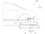
- FIG. 4 is a diagram showing a state in which the airbag 11 of the airbag module 1 according to this modification is deployed.
- the airbag 11 when the airbag 11 is deployed, the airbag 11 extends from the position of the main body 10 toward the front of the vehicle 100, and extends from the main body 10 toward the rear of the vehicle 100. It has an existing rear deployment portion 11B.
- L1 When the length from the position of the main body portion 10 to the tip of the front deploying portion 11A is L1 and the length from the position of the main body portion 10 to the tip of the rear deploying portion 11B is L2, L1 is shorter than L2.
- the length from the position of the main body portion 10 to the tip of the front deploying portion 11A is shorter than the length from the position to the tip of the rear deploying portion 11B.
- the position of the main body 10 is the center of the main body 10 in the front-rear direction of the vehicle 100.
- the airbag module 1 is configured so that the front deploying portion 11A deployed in front of the vehicle 100 is shorter than the rear deploying portion 11B deployed in the rear of the vehicle 100.
- the cover 13 is fixed to the front unfolding portion 11A.
- the airbag module 1 fills the gap under the vehicle 100 by making the amount of rearward deployment of the airbag 11 smaller than the amount of rearward deployment, and the cover 13 covers the airbag 11 when the vehicle 100 is moving forward. Even when the vehicle comes into contact with the ground G, the possibility that the front deploying portion 11A is caught behind the vehicle 100 can be reduced. As a result, the airbag module 1 can prevent pedestrians from being pinched between the vehicle 100 and the ground G, and thus can protect pedestrians.
- the airbag module 1 according to the present embodiment is mounted on a vehicle such as an automobile, and is exemplified as a device for preventing the prime mover of the vehicle from being submerged in the event of flood damage or the like.
- FIG. 5 is a view when the vehicle 100 on which the airbag module 1 according to the second embodiment is mounted is viewed from the right side.
- a motor 102 is mounted in front of the vehicle 100.
- the prime mover is a drive source of the vehicle 100, and includes, for example, an engine and a motor.
- the airbag module 1 according to the present embodiment is arranged at a position corresponding to the prime mover 102 of the vehicle 100. In the present embodiment, the position corresponding to the prime mover 102 of the vehicle 100 is in front of the vehicle 100. Further, the airbag 11 is deployed including the position corresponding to the motor 102.
- the airbag module 1 is a device for preventing the prime mover 102 from being submerged by deploying the airbag 11 when the vehicle 100 is submerged.
- the rear portion of the vehicle 100 is submerged in the water surface WS.
- the front portion of the vehicle 100 can be lifted above the water surface WS by the buoyancy of the airbag 11.
- the airbag module 1 can prevent the motor 102 itself from being submerged, thereby preventing the motor 102 itself from being submerged.
- the airbag module 1 can be self-propelled only by replacing auxiliary equipment such as a battery of the vehicle 100 after the water has been drained, and facilitates the movement of the vehicle 100 after flood damage. Can be done. Further, the airbag module 1 levitates the corresponding position of the prime mover 102 of the vehicle 100 and submerges the rear portion of the vehicle 100, so that the vehicle 100 is easily caught by obstacles in the vicinity and the vehicle 100 may be swept away. Can be reduced.
- the airbag module 1 floats the air intake portion of the engine from the water surface WS so that water enters the cylinder of the engine even if the muffler 103 is submerged. Can be prevented. Further, even when the motor includes a motor, the airbag module 1 can make the vehicle 100 self-propelled by floating the motor from the water surface WS and replacing only the battery. Therefore, the airbag module 1 according to the present embodiment can prevent the prime mover of the vehicle 100 from being submerged in the event of flood damage or the like. When the airbag module 1 deploys the airbag 11 in the event of a flood or the like, the vehicle 100 may be provided with a sensor for detecting submersion in addition to a sensor for approaching a collision or an obstacle.
- the airbag module 1 according to the present embodiment is mounted at the rear of a vehicle such as an automobile. As in the present embodiment, the airbag module 1 may be attached to the rear of the vehicle 100. As a result, for example, even when the rear portion collides with a pedestrian while the vehicle 100 is moving backward, or when there is a high possibility of colliding with a pedestrian (when the collision cannot be avoided), the airbag module 1 can be used with the vehicle 100. The pedestrian can be protected by preventing the pedestrian from being caught between the ground G and the ground G.
- the airbag module 1 can prevent the prime mover of the vehicle 100 from being submerged in the event of flood damage or the like.
- the various embodiments described above can be combined as much as possible.
- the airbag module 1 has been described in the above embodiment, the technique of the present disclosure is not limited to this, and the technique of the present disclosure may be a vehicle 100 provided with the airbag module 1.
- Airbag module 10 Main body 10A Storage space 10B Bottom 11 Airbag 11A Front deployment 11B Rear deployment 12 Opening 13 Cover 14 Vulnerable 15 Gas generator 100 Vehicle 101 Bottom 102 Motor 103 Muffler A Arrow G Ground WS Water surface
Landscapes
- Engineering & Computer Science (AREA)
- Mechanical Engineering (AREA)
- Air Bags (AREA)
Abstract
本開示は、エアバッグの製造コストが増大するのを抑制しつつ、エアバッグの破損を防ぐことができる技術を提供することを目的とする。 エアバッグモジュールは、車両の前方または後方に取り付けられる。エアバッグモジュールは、車両に配置され、エアバッグを収納する収納空間を有する本体部と、収納空間と車両の底面の外側とを連通する開口部であって、地面に向かうように配置された開口部と、収納空間に収納されたエアバッグであって、ガスが供給されることにより開口部から車両の底面と地面の間に展開するエアバッグと、開口部を覆い、収納空間に収納されたエアバッグの少なくとも一部が固定されたカバーであって、エアバッグが展開する際にエアバッグと一体になって本体部から脱落するように構成されたカバーと、を備える。
Description
本開示は、エアバッグモジュールおよびそれを備えた車両に関する。
従来、車両の外側で展開するように車両に搭載されたエアバッグが知られている。例えば、特許文献1には、車両の前部のバンパーから車両の外側に展開して歩行者を保護するガスバッグが記載されている。このガスバッグは、路面に向かって展開した場合に、路面からわずかな距離を隔てつつ歩行者の脚部と接触する。また、ガスバッグの展開状態で路面と面する領域には、摩擦による負荷に対して高い耐性を有する外層や別個の着用体が内層に取り付けられている。
車両の外側で展開するエアバッグでは、展開後に地面との間に隙間が形成できるように構成されていたとしても、エアバッグが展開する際には展開時の勢いによってその一部が地面と接触する可能性が有る。エアバッグは、地面と接触することで地面との摩擦による負荷がかかり破損してしまう虞がある。
また、エアバッグの破損を防ぐために、摩擦による負荷に対して高い耐性を有するカバー等をエアバッグに取り付けることが想定されるが、エアバッグの路面と面する領域のうちいずれの部分が地面と接触するのかの予測が困難である。このため、エアバッグのいずれの部分にカバー等を取り付けるべきであるかの特定をすることは困難である。また、エアバッグの全体にカバー等を取り付ける場合には、エアバッグの製造コストの増大を招いてしまう。
本開示は、上記した実情に鑑みてなされたものであり、製造コストが増大するのを抑制しつつ、エアバッグの破損を防ぐことができる技術を提供することを目的とする。
上記課題を解決するために、本開示のエアバッグモジュールでは、エアバッグが展開する際に該エアバッグと一体になって本体部から脱落するようにカバーを設けた。
具体的には、本開示は、車両の前方または後方に取り付けられるエアバッグモジュールであって、前記車両に配置され、エアバッグを収納する収納空間を有する本体部と、前記収納空間と前記車両の底面の外側とを連通する開口部であって、地面に向かうように配置された開口部と、前記収納空間に収納された前記エアバッグであって、ガスが供給されることにより前記開口部から該車両の底面と地面の間に展開する前記エアバッグと、前記開口部を覆い、前記収納空間に収納された前記エアバッグの少なくとも一部が固定されたカバーであって、前記エアバッグが展開する際に該エアバッグと一体になって前記本体部から脱落するように構成されたカバーと、を備える。このような構成のエアバッグモジュールによれば、エアバッグの広範囲にカバーを設ける必要がなく、簡易な構成にすることで安価に製造することができる。このため、上記構成のエアバッグモジュールは、生産コストが増大するのを抑制しつつ、エアバッグの破損を防ぐことができる。また、上記構成のエアバッグモジュールは、展開時におけるエアバッグの破損を防ぐことができるので、歩行者が車両と地面の間に挟まれにくくすることができる。
上記エアバッグモジュールにおいて、前記カバーは、展開した前記エアバッグのうち前記地面との距離が最も近い部分の少なくとも一部を覆うように該エアバッグに固定されていてもよい。このような構成のエアバッグモジュールによれば、エアバッグが展開したときに地面と最も近接するエアバッグの部分のみをカバーで覆うことができるので、全体をコンパクトに構成することができる。
上記エアバッグモジュールにおいて、前記カバーは、前記本体部と一体的に構成されており、前記本体部には、前記カバーを区画する脆弱部が形成されていてもよい。なお、脆弱部は、直線状または曲線状に形成されていてもよく、連続的または点線状に形成されていてもよい。
上記エアバッグモジュールは、前記車両の前方に取り付けられており、前記エアバッグは、展開した場合において、前記本体部の位置から前記車両の前方に向かって延在する前方展開部と、該本体部から該車両の後方に向かって延在する後方展開部とを有しており、前記本体部の位置から前記前方展開部の先端までの長さは、該位置から前記後方展開部の先端までの長さより短くてもよい。このような構成のエアバッグモジュールによれば、エアバッグの前方への展開量を後方への展開量よりも小さくすることで、車両の下の隙間を埋めつつ、車両が前進しているときにカバーが地面に接触した場合であっても前方展開部が車両の後方に巻き込まれる可能性を低減できる。
上記エアバッグモジュールは、前記車両が有する原動機に対応する位置に配置されており、前記エアバッグは、前記原動機に対応する位置を含んで展開されてもよい。このような構成のエアバッグモジュールによれば、水害等の発生時に車両の原動機の水没も防ぐことができる。
また、本開示は、車両の側面から捉えることもできる。例えば、本開示は、上記のいずれかに記載のエアバッグモジュールを備える車両であってもよい。
本開示の技術によれば、エアバッグの製造コストが増大するのを抑制しつつ、エアバッグの破損を防ぐことができる。
以下に、図面を参照して本開示の実施形態に係るエアバッグモジュールについて説明する。なお、各実施形態における各構成及びそれらの組み合わせ等は、一例であって、本開示の主旨から逸脱しない範囲内で、適宜、構成の付加、省略、置換、及びその他の変更が可能である。本開示は、実施形態によって限定されることはなく、請求項によってのみ限定される。
<実施形態1>
実施形態1に係るエアバッグモジュールについて説明する。本実施形態に係るエアバッグモジュールは、自動車等の車両に搭載され、歩行者を保護するための装置として例示される。
実施形態1に係るエアバッグモジュールについて説明する。本実施形態に係るエアバッグモジュールは、自動車等の車両に搭載され、歩行者を保護するための装置として例示される。
図1は、実施形態1に係るエアバッグモジュール1が搭載された車両100を右側から見た場合の図である。図中、矢印Aは、車両100が前進する場合の進行方向を示している。本実施形態に係るエアバッグモジュール1は、車両100の前方に取り付けられており、車両100の底面101と地面Gの間でエアバッグを展開させる。これにより、エアバッグモジュール1は、車両100と地面Gの間に歩行者が挟まれるのを防ぐことで歩行者を保護する。
次に、図2に基づいて、本実施形態に係るエアバッグモジュール1についてより詳細に説明する。図2は、本実施形態に係るエアバッグモジュール1の外観斜視図である。エアバッグモジュール1は、図1に示す車両100の内部に配置された本体部10とエアバッグ11とを備える。本体部10は、箱状に形成されており、内部にエアバッグ11を収納する収納空間10Aを有する。収納空間10Aには、布製のエアバッグ11が折り畳まれて収容されている。本体部10は、樹脂で形成された底面部10Bを除いて金属で形成されており、金属部分で樹脂製の底面部10Bをかしめやねじによる固定等の公知の方法によって全体が一体的に構成されている。なお、本体部10は、全体が金属または樹脂で形成されていてもよい。
エアバッグモジュール1は、本体部10の底面部10Bが車両100の底面側を向くように車両100内に配置される。エアバッグモジュール1は、地面Gに向かうように、底面部10Bに配置された開口部12を備える。開口部12は、収納空間10Aと車両100の底面101の外側とを連通する。エアバッグ11は、ガスが供給されることによって開口部12から車両100の底面101と地面Gの間に展開する。
また、エアバッグモジュール1は、非作動状態において開口部12を覆うカバー13を備える。カバー13は、布製のエアバッグ11よりも摩擦による負荷に対して高い耐性を有する。本実施形態では、カバー13は、本体部10あるいは底面部10Bと一体的に構成されており、底面部10Bには、カバー13を区画する脆弱部14が形成されている。エアバッグ11が展開する際に、エアバッグ11がカバー13を押し下げることによって脆弱部14に荷重がかかることで脆弱部14が破壊され、カバー13が底面部10Bから脱落する。これにより、開口部12が開口状態となる。このように、脆弱部14は、エアバッグ11の展開時に開口部12を開口状態とするために形成されている。脆弱部14は、所定の荷重を受けたときに他の部位よりも優先的に破壊する部位であり、周囲(例えば、カバー13や底面部10B)よりも肉厚が薄くなっていたり、強度が低くなっている部位である。なお、脆弱部14は、直線上に連続的に形成されていてもよいし、直線状に点線状に形成されていてもよい。脆弱部14は、底面部10Bに容易に形成することができ、エアバッグ11の展開時には再現性よく開口部12を開口状態とすることができる。これにより、エアバッグモジュール1は、エアバッグ11を開口部12から展開させることができる。
カバー13には、収納空間10Aに収納されたエアバッグ11の少なくとも一部が固定されている。このエアバッグ11の一部とは、エアバッグ11の展開後にも地面Gを向く部分のことである。カバー13に対するエアバッグ11の固定は、例えば、接着剤によってカバー13にエアバッグ11が接着されることによって実現される。カバー13は、エアバッグ11が展開する際にエアバッグ11と一体になって本体部10の底面部10Bから脱落するように構成されている。なお、カバー13は、エアバッグ11が展開する際にエアバッグ11と一体になって本体部10から脱落するように本体部10と別体で構成されて底面部10Bに接合されていてもよい。
また、エアバッグモジュール1は、エアバッグ11に供給するガスを発生させるガス発生器15を備える。ガス発生器15は、金属で形成された外殻容器内に充填されたガス発生器を点火器によって燃焼させることによって燃焼ガスを発生させる。なお、ガス発生器15は、圧縮ガスとガス発生剤が外殻容器内に封入されており、圧縮ガスおよび燃焼ガスを供給するハイブリッド式や、圧縮ガスのみを供給するストアード式であってもよい。なお、エアバッグモジュール1は、車両100に搭載されている別のガス発生器から供給されるガスによってエアバッグを展開するように構成されていてもよい。
図3は、車両100に搭載されたエアバッグモジュール1のエアバッグ11が展開した状態を示す図である。エアバッグモジュール1は、車両100が歩行者や障害物との衝突したこと、または歩行者や障害物と衝突する可能性が高いこと(衝突を回避できないこと)を検知する信号を受信した場合に、ガス発生器15を作動させることによってエアバッグ11を展開する。例えば、車両100が矢印Aの向きに進行している場合に車両100の前方が歩行者に衝突したり、衝突する可能性が高い場合に、当該歩行者が車両100のボンネットに持ち上げられた後に運転手のブレーキ操作によって車両100が急停車されることが想定される。この場合、車両の急減速により生じる慣性力によって歩行者は車両100の前方に転げ落ちる。エアバッグモジュール1は、当該歩行者と車両100の衝突発生時、または衝突直前にエアバッグ11を展開しているため、車両100の前方に転げ落ちた当該歩行者を車両100が底面101と地面Gの間に巻き込むことを防ぐことができる。
エアバッグ11の展開時においては、初めにエアバッグ11は、地面Gに向かって膨張し、次いで、車両100の前方に向かって膨張する。このように、エアバッグモジュール1は、歩行者が車両100の下に入り込まないように、車両100と地面Gとの間の隙間を埋めるようにエアバッグ11を展開させる。エアバッグ11が展開した状態では、エアバッグ11と地面Gとの間に例えば、2cm~5cm程度の隙間が形成されるが、エアバッグ11の展開中には、エアバッグ11内に供給されるガスの勢いによってエアバッグの一部が地面Gに接触してしまう虞がある。この問題点に関し、本実施形態に係るエアバッグモジュール1は、エアバッグ11の一部が固定されたカバー13をエアバッグ11の展開時に本体部10から脱落させることで、地面Gと接触する可能性のある領域をカバー13で覆った状態でエアバッグ11を展開させることができる。エアバッグモジュール1は、カバー13によってエアバッグ11が地面Gに接触するのを防ぎ、車両100が矢印Aの方向に進行している際にエアバッグ11を展開させたとしてもカバー13を地面Gと擦れさせ、エアバッグ11を保護することができる。すなわち、エアバッグ11が展開したときに、当該エアバッグ11のうち地面Gと接触する可能性の高い領域のみがカバー13で覆われている。
本実施形態に係るエアバッグモジュール1は、カバー13によって覆うべきエアバッグ11の領域をある程度定めることができ、上記特許文献1に記載された外層や別個の着用体よりも厚みのあるカバー13によってエアバッグ11を保護することができるため、エアバッグ11を地面Gと接触する可能性をほぼ無くすことができる。そのため、エアバッグモジュール1は、エアバッグ11の広範囲にカバーを設ける必要がなく、簡易な構成にすることで安価に製造することができる。また、エアバッグ11の全体を厚く形成する必要がなく、エアバッグ11をエアバッグモジュール1内に収容する際もエアバッグ11が嵩張ることがない。このため、本実施形態に係るエアバッグモジュール1は、生産コストが増大するのを抑制しつつ、エアバッグ11の破損を防ぐことができる。なお、カバー13は、エアバッグ11の展開時の最初の段階で地面Gに接触する虞のあるエアバッグ11の領域を少なくとも覆うことができる面積を有していればよい。
また、エアバッグモジュール1において、好ましくは、カバー13は、展開したエアバッグ11のうち地面Gとの距離が最も近い部分の少なくとも一部を覆うようにエアバッグ11に固定されていてもよい。エアバッグ11は、地面Gを向く部分が地面と必ずしも平行にならず、車両100の前方に向かって地面Gとエアバッグ11の底面との距離が増大するように形成されていてもよい。エアバッグ11の展開時と展開後において、地面Gと接触する可能性が高いのは地面Gとの距離が最小になる部分である。カバー13は、この部分を覆うことによってエアバッグ11が地面Gに接触することを防ぎ、エアバッグ11が破損するのを防ぐことができる。
また、エアバッグ11が展開したときに地面Gと最も近接するエアバッグ11の部分のみをカバー13で覆うことによって、それ以外のエアバッグ11はカバー13で覆う必要がない。このため、エアバッグモジュール1は、コンパクトに構成することができる。また、地面Gと最も近接するエアバッグ11の部分においも地面Gと隙間が形成されるようにエアバッグ11の大きさを設定することで、エアバッグ11の当該部分以外はさらに地面Gとの隙間を広くすることができる。よってエアバッグモジュール1は、エアバッグ11の展開時に、エアバッグ11の一部が地面Gと擦れて破損することを防ぐことができる。これにより、エアバッグモジュール1は、展開時におけるエアバッグ11の破損を防ぐことができるので、歩行者が車両100と地面Gの間に挟まれるのを防ぐことができる。
<変形例>
次に、本実施形態の変形例に係るエアバッグモジュール1について図4に基づいて説明する。図4は、本変形例に係るエアバッグモジュール1のエアバッグ11が展開した状態を示す図である。本変形例においては、エアバッグ11は、展開した場合において、本体部10の位置から車両100の前方に向かって延在する前方展開部11Aと、本体部10から車両100の後方に向かって延在する後方展開部11Bとを有している。本体部10の位置から前方展開部11Aの先端までの長さをL1とし、本体部10の位置から後方展開部11Bの先端までの長さをL2すると、L1はL2よりも短い。すなわち、本体部10の位置から前方展開部11Aの先端までの長さは、当該位置から後方展開部11Bの先端までの長さより短い。ここで、本体部10の位置は、車両100の前後方向における本体部10の中央である。
次に、本実施形態の変形例に係るエアバッグモジュール1について図4に基づいて説明する。図4は、本変形例に係るエアバッグモジュール1のエアバッグ11が展開した状態を示す図である。本変形例においては、エアバッグ11は、展開した場合において、本体部10の位置から車両100の前方に向かって延在する前方展開部11Aと、本体部10から車両100の後方に向かって延在する後方展開部11Bとを有している。本体部10の位置から前方展開部11Aの先端までの長さをL1とし、本体部10の位置から後方展開部11Bの先端までの長さをL2すると、L1はL2よりも短い。すなわち、本体部10の位置から前方展開部11Aの先端までの長さは、当該位置から後方展開部11Bの先端までの長さより短い。ここで、本体部10の位置は、車両100の前後方向における本体部10の中央である。
本変形例に係るエアバッグモジュール1は、車両100の前方に展開する前方展開部11Aを車両100の後方に展開する後方展開部11Bよりも短く構成している。なお、前方展開部11Aにカバー13が固定されている。エアバッグモジュール1は、エアバッグ11の前方への展開量を後方への展開量よりも小さくすることで、車両100の下の隙間を埋めつつ、車両100が前進しているときにカバー13が地面Gに接触した場合であっても前方展開部11Aが車両100の後方に巻き込まれる可能性を低減できる。これにより、エアバッグモジュール1は、歩行者が車両100と地面Gの間に挟まれにくくすることができるので、歩行者を保護できる。
<実施形態2>
次に、実施形態2に係るエアバッグモジュールについて説明する。本実施形態に係るエアバッグモジュール1は、自動車等の車両に搭載され、水害等の発生時に車両の原動機の水没を防ぐための装置として例示される。
次に、実施形態2に係るエアバッグモジュールについて説明する。本実施形態に係るエアバッグモジュール1は、自動車等の車両に搭載され、水害等の発生時に車両の原動機の水没を防ぐための装置として例示される。
図5は、実施形態2に係るエアバッグモジュール1が搭載された車両100を右側から見た場合の図である。車両100の前方には、原動機102が搭載されている。原動機は、車両100の駆動源であり、例えば、エンジンやモータを含んで構成されている。本実施形態に係るエアバッグモジュール1は、車両100が有する原動機102に対応する位置に配置されている。本実施形態において車両100が有する原動機102に対応する位置は、車両100の前方である。また、エアバッグ11は、原動機102に対応する位置を含んで展開される。
本実施形態に係るエアバッグモジュール1は、車両100が水没した場合にエアバッグ11を展開させることで、原動機102が水没するのを防ぐための装置である。図5に示す状態では、車両100は水面WSの中に後方部分が水没している。しかしながら、エアバッグモジュール1のエアバッグ11が展開することによって、エアバッグ11の浮力により車両100の前方部分を水面WSよりも浮揚させることができる。これにより、エアバッグモジュール1は、原動機102が水没するのを防ぐことで、原動機102自体が水没により故障するのを防ぐことができる。このため、エアバッグモジュール1は、水が引いた後に、車両100のバッテリーなどの補器類を交換する程度で自走可能とすることができ、水害後の車両100の移動を容易にすることができる。またエアバッグモジュール1は、車両100の原動機102の対応する位置を浮揚させ、車両100の後方部分を水没させるため車両100が周辺の障害物に引っかかりやすく、車両100が遠方に流される可能性を低減できる。
また、原動機102にエンジンが含まれる場合には、エアバッグモジュール1は、エンジンのエアインテーク部を水面WSから浮揚させることで、マフラー103が水没したとしてもエンジンのシリンダー内に水が入るのを防ぐことができる。また、原動機にモータが含まれる場合でも、エアバッグモジュール1は、モータを水面WSから浮揚させることで、バッテリーのみ交換すれば車両100を自走可能とすることができる。このため、本実施形態に係るエアバッグモジュール1は、水害等の発生時に車両100の原動機の水没も防ぐことができる。なお、エアバッグモジュール1が水害時等でエアバッグ11を展開させる場合には、衝突や障害物への接近センサー以外にも、水没を感知するセンサーが車両100に設けられてもよい。
<実施形態3>
次に、実施形態3に係るエアバッグモジュールについて説明する。本実施形態に係るエアバッグモジュール1は、自動車等の車両の後方に搭載されている。本実施形態のように、エアバッグモジュール1は、車両100の後方に取り付けられていてもよい。これにより、例えば、車両100が後進中に後方部分が歩行者に衝突した場合や、歩行者と衝突する可能性が高い場合(衝突を回避できない場合)においても、エアバッグモジュール1は、車両100と地面Gの間に歩行者が挟まれるのを防ぐことで歩行者を保護できる。また、車両100の後方に原動機が搭載されている場合においても、車両100が有する原動機に対応する位置にエアバッグモジュール1を配置することで、エアバッグ11を原動機に対応する位置を含んで展開することができる。これにより、本実施形態に係るエアバッグモジュール1は、水害等の発生時に車両100の原動機の水没も防ぐことができる。
次に、実施形態3に係るエアバッグモジュールについて説明する。本実施形態に係るエアバッグモジュール1は、自動車等の車両の後方に搭載されている。本実施形態のように、エアバッグモジュール1は、車両100の後方に取り付けられていてもよい。これにより、例えば、車両100が後進中に後方部分が歩行者に衝突した場合や、歩行者と衝突する可能性が高い場合(衝突を回避できない場合)においても、エアバッグモジュール1は、車両100と地面Gの間に歩行者が挟まれるのを防ぐことで歩行者を保護できる。また、車両100の後方に原動機が搭載されている場合においても、車両100が有する原動機に対応する位置にエアバッグモジュール1を配置することで、エアバッグ11を原動機に対応する位置を含んで展開することができる。これにより、本実施形態に係るエアバッグモジュール1は、水害等の発生時に車両100の原動機の水没も防ぐことができる。
以上、本開示の実施形態について説明したが、上述した種々の実施形態は可能な限り組み合わせることができる。上記実施形態では、エアバッグモジュール1について説明したが、本開示の技術はこれに限られず、本開示の技術は、エアバッグモジュール1を備える車両100であってもよい。
本明細書に開示された各々の態様は、本明細書に開示された他のいかなる特徴とも組み合わせることができる。
1 エアバッグモジュール
10 本体部
10A 収納空間
10B 底面部
11 エアバッグ
11A 前方展開部
11B 後方展開部
12 開口部
13 カバー
14 脆弱部
15 ガス発生器
100 車両
101 底面
102 原動機
103 マフラー
A 矢印
G 地面
WS 水面
10 本体部
10A 収納空間
10B 底面部
11 エアバッグ
11A 前方展開部
11B 後方展開部
12 開口部
13 カバー
14 脆弱部
15 ガス発生器
100 車両
101 底面
102 原動機
103 マフラー
A 矢印
G 地面
WS 水面
Claims (6)
- 車両の前方または後方に取り付けられるエアバッグモジュールであって、
前記車両に配置され、エアバッグを収納する収納空間を有する本体部と、
前記収納空間と前記車両の底面の外側とを連通する開口部であって、地面に向かうように配置された開口部と、
前記収納空間に収納された前記エアバッグであって、ガスが供給されることにより前記開口部から該車両の底面と地面の間に展開する前記エアバッグと、
前記開口部を覆い、前記収納空間に収納された前記エアバッグの少なくとも一部が固定されたカバーであって、前記エアバッグが展開する際に該エアバッグと一体になって前記本体部から脱落するように構成されたカバーと、
を備える、エアバッグモジュール。 - 前記カバーは、展開した前記エアバッグのうち前記地面との距離が最も近い部分の少なくとも一部を覆うように該エアバッグに固定されている、
請求項1記載のエアバッグモジュール。 - 前記カバーは、前記本体部と一体的に構成されており、
前記本体部には、前記カバーを区画する脆弱部が形成されている、
請求項1または請求項2に記載のエアバッグモジュール。 - 前記エアバッグモジュールは、前記車両の前方に取り付けられており、
前記エアバッグは、展開した場合において、前記本体部の位置から前記車両の前方に向かって延在する前方展開部と、該本体部から該車両の後方に向かって延在する後方展開部とを有しており、
前記本体部の位置から前記前方展開部の先端までの長さは、該位置から前記後方展開部の先端までの長さより短い、
請求項1から請求項3いずれか一項に記載のエアバッグモジュール。 - 前記エアバッグモジュールは、前記車両が有する原動機に対応する位置に配置されており、
前記エアバッグは、前記原動機に対応する位置を含んで展開される、
請求項1から4のいずれか一項に記載のエアバッグモジュール。 - 請求項1から5のいずれか一項に記載のエアバッグモジュールを備える車両。
Applications Claiming Priority (2)
| Application Number | Priority Date | Filing Date | Title |
|---|---|---|---|
| JP2020-127441 | 2020-07-28 | ||
| JP2020127441A JP7465744B2 (ja) | 2020-07-28 | 2020-07-28 | エアバッグモジュールおよびそれを備えた車両 |
Publications (1)
| Publication Number | Publication Date |
|---|---|
| WO2022024696A1 true WO2022024696A1 (ja) | 2022-02-03 |
Family
ID=80037315
Family Applications (1)
| Application Number | Title | Priority Date | Filing Date |
|---|---|---|---|
| PCT/JP2021/025611 Ceased WO2022024696A1 (ja) | 2020-07-28 | 2021-07-07 | エアバッグモジュールおよびそれを備えた車両 |
Country Status (2)
| Country | Link |
|---|---|
| JP (1) | JP7465744B2 (ja) |
| WO (1) | WO2022024696A1 (ja) |
Citations (6)
| Publication number | Priority date | Publication date | Assignee | Title |
|---|---|---|---|---|
| JPH07277114A (ja) * | 1994-04-14 | 1995-10-24 | Hino Motors Ltd | 衝撃物体の潜り込み防止装置 |
| JP2002542110A (ja) * | 1999-04-22 | 2002-12-10 | バイエル アクチェンゲゼルシャフト | 衝撃センサーにより制御されるエネルギー−吸収素子を含んで成る安全緩衝装置 |
| JP2005199787A (ja) * | 2004-01-14 | 2005-07-28 | Toyota Motor Corp | 地面エアバッグ装置 |
| JP2006137322A (ja) * | 2004-11-12 | 2006-06-01 | Toyoda Gosei Co Ltd | 歩行者用エアバッグ装置 |
| JP2006273139A (ja) * | 2005-03-29 | 2006-10-12 | Toyoda Gosei Co Ltd | 歩行者用エアバッグ装置 |
| DE102011114298A1 (de) * | 2011-09-23 | 2013-03-28 | Volkswagen Aktiengesellschaft | Kraftfahrzeug mit einem Bremselement |
-
2020
- 2020-07-28 JP JP2020127441A patent/JP7465744B2/ja active Active
-
2021
- 2021-07-07 WO PCT/JP2021/025611 patent/WO2022024696A1/ja not_active Ceased
Patent Citations (6)
| Publication number | Priority date | Publication date | Assignee | Title |
|---|---|---|---|---|
| JPH07277114A (ja) * | 1994-04-14 | 1995-10-24 | Hino Motors Ltd | 衝撃物体の潜り込み防止装置 |
| JP2002542110A (ja) * | 1999-04-22 | 2002-12-10 | バイエル アクチェンゲゼルシャフト | 衝撃センサーにより制御されるエネルギー−吸収素子を含んで成る安全緩衝装置 |
| JP2005199787A (ja) * | 2004-01-14 | 2005-07-28 | Toyota Motor Corp | 地面エアバッグ装置 |
| JP2006137322A (ja) * | 2004-11-12 | 2006-06-01 | Toyoda Gosei Co Ltd | 歩行者用エアバッグ装置 |
| JP2006273139A (ja) * | 2005-03-29 | 2006-10-12 | Toyoda Gosei Co Ltd | 歩行者用エアバッグ装置 |
| DE102011114298A1 (de) * | 2011-09-23 | 2013-03-28 | Volkswagen Aktiengesellschaft | Kraftfahrzeug mit einem Bremselement |
Also Published As
| Publication number | Publication date |
|---|---|
| JP2022024702A (ja) | 2022-02-09 |
| JP7465744B2 (ja) | 2024-04-11 |
Similar Documents
| Publication | Publication Date | Title |
|---|---|---|
| US8955634B2 (en) | Pedestrian protection airbag | |
| EP1024063A2 (en) | Vehicle bumper and hood airbag system | |
| US20120049491A1 (en) | Airbag module | |
| JP5983663B2 (ja) | 歩行者保護エアバッグ装置 | |
| JP6063976B2 (ja) | 車外用エアバッグ | |
| EP3222475B1 (en) | Dashboard protection arrangement | |
| US20040262894A1 (en) | Hood airbag for pedestrian protection | |
| WO2018173514A1 (ja) | 車両用保護装置及び車両 | |
| JP2001334895A (ja) | 車両用歩行者保護装置 | |
| JP2001322518A (ja) | 車両用歩行者保護装置 | |
| JP2007112183A (ja) | 車外用エアバッグ装置 | |
| JP7465744B2 (ja) | エアバッグモジュールおよびそれを備えた車両 | |
| JP2000168473A (ja) | 歩行者保護用エアバッグ装置 | |
| US20040207185A1 (en) | Air bag device and motorbike with air bag device | |
| JP2003306098A (ja) | 車両外置きエアバック装置 | |
| JP2006044325A (ja) | 車両用歩行者保護装置 | |
| US11027692B2 (en) | Air bag device | |
| JP6137075B2 (ja) | 歩行者保護エアバッグ装置 | |
| JP2006205934A (ja) | エアバッグ及び非乗員保護装置 | |
| JP2005138750A (ja) | 歩行者等の保護機構を備えた車両及びエアバッグ装置 | |
| JP2007131056A (ja) | 運転席用エアバッグ装置 | |
| JP3932183B2 (ja) | 衝突物保護装置 | |
| JP2004175154A (ja) | 衝突物保護装置 | |
| JP4278472B2 (ja) | 歩行者保護装置 | |
| JP2001063499A (ja) | 車両の衝撃緩和装置 |
Legal Events
| Date | Code | Title | Description |
|---|---|---|---|
| 121 | Ep: the epo has been informed by wipo that ep was designated in this application |
Ref document number: 21850559 Country of ref document: EP Kind code of ref document: A1 |
|
| NENP | Non-entry into the national phase |
Ref country code: DE |
|
| 122 | Ep: pct application non-entry in european phase |
Ref document number: 21850559 Country of ref document: EP Kind code of ref document: A1 |