WO2022024319A1 - 数値制御装置および数値制御システム - Google Patents
数値制御装置および数値制御システム Download PDFInfo
- Publication number
- WO2022024319A1 WO2022024319A1 PCT/JP2020/029319 JP2020029319W WO2022024319A1 WO 2022024319 A1 WO2022024319 A1 WO 2022024319A1 JP 2020029319 W JP2020029319 W JP 2020029319W WO 2022024319 A1 WO2022024319 A1 WO 2022024319A1
- Authority
- WO
- WIPO (PCT)
- Prior art keywords
- numerical control
- image processing
- image
- information
- control device
- Prior art date
- Legal status (The legal status is an assumption and is not a legal conclusion. Google has not performed a legal analysis and makes no representation as to the accuracy of the status listed.)
- Ceased
Links
Images


Classifications
-
- G—PHYSICS
- G05—CONTROLLING; REGULATING
- G05B—CONTROL OR REGULATING SYSTEMS IN GENERAL; FUNCTIONAL ELEMENTS OF SUCH SYSTEMS; MONITORING OR TESTING ARRANGEMENTS FOR SUCH SYSTEMS OR ELEMENTS
- G05B19/00—Program-control systems
- G05B19/02—Program-control systems electric
- G05B19/18—Numerical control [NC], i.e. automatically operating machines, in particular machine tools, e.g. in a manufacturing environment, so as to execute positioning, movement or co-ordinated operations by means of program data in numerical form
- G05B19/414—Structure of the control system, e.g. common controller or multiprocessor systems, interface to servo, programmable interface controller
- G05B19/4148—Structure of the control system, e.g. common controller or multiprocessor systems, interface to servo, programmable interface controller characterised by using several processors for different functions, distributed (real-time) systems
Definitions
- the present disclosure relates to a numerical control device and a numerical control system having an image processing function.
- the numerical control device described in Patent Document 1 can be retrofitted as a personal computer function card having a display function and an operation function so that the entire control board does not need to be replaced when the display function and the operation function are improved.
- Hardware is attached to the main body.
- the numerical control device described in Patent Document 1 improves the display function and the operation function by exchanging the hardware that can be retrofitted.
- the processor and the graphic control circuit included in the hardware that can be retrofitted generate the video data and transmit it to the main body side in only one direction. Therefore, the technique of Patent Document 1 has a problem that the information on the main body side necessary for display cannot be effectively utilized.
- the present disclosure has been made in view of the above, and an object thereof is to obtain a numerical control device that effectively utilizes information on the main body side when displaying an image acquired from hardware that can be retrofitted.
- the numerical control device of the present disclosure is a control function for controlling a first controlled device, a first display used for displaying a display screen by the first display device. It has a control board including a first image processing unit for creating image data and a first image processing unit having a first data communication function. Further, the numerical control device of the present disclosure has a second image processing function for creating a second image data used for display from an image captured by the image pickup device, and a second data communication function. It is equipped with an image processing unit and has an expansion board that can be attached to and detached from the control board. The first image processing function creates the first image data using the data on the control board.
- the first data communication function is a function of executing communication with the expansion board
- the second data communication function is a function of executing communication with the control board.
- the numerical control device has the effect that the information on the main body side can be effectively utilized when displaying the image acquired from the hardware that can be retrofitted.
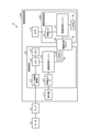
- FIG. 1 is a diagram showing a configuration of a numerical control system including the numerical control device according to the first embodiment.
- the numerical control system 1A includes a numerical control device 10A, an amplifier 3, and a motor 2.
- the numerical control device 10A includes a control board 20, a display 11, a function expansion board 30A, and a camera 12.
- the control board 20 is a board arranged in the main body of the numerical control device 10A.
- the control board 20 has a control function for controlling the motor 2 which is the first controlled device.
- the control board 20 includes a motor control communication IF (InterFace, interface) 21 and a CPU (Central Processing Unit, central processing unit, processing unit, arithmetic unit, microprocessor, microcomputer, DSP (Digital Signal Processor)) 22. It has a video output IF 23, an image processing engine 24, a VRAM (Video Random Access Memory) 25, an inter-engine communication bus 26, a memory 27, and a function expansion slot 40.
- the function expansion board 30A which is an expansion board for expanding the function, has an image processing engine 31, a VRAM 32, a video input IF 33, and an inter-engine communication bus 38.
- the motor control communication IF21 is connected to the amplifier 3, and the amplifier 3 is connected to the motor 2.
- the motor control communication IF 21 executes communication with the amplifier 3.
- the video output IF 23 is connected to the display 11.
- the function expansion board 30A is removable from the function expansion slot 40.
- FIG. 1 shows a state in which the function expansion board 30A is attached to the function expansion slot 40.
- the CPU 22 controls the entire numerical control device 10A. Further, the CPU 22 controls, for example, the motor 2.
- the CPU 22 transmits a command signal for motor control, that is, a control signal, to the amplifier 3 via the motor control communication IF 21.
- the amplifier 3 drives the motor 2 according to the command signal received from the CPU 22.
- the CPU 22 receives the feedback signal from the motor 2 via the amplifier 3 and the motor control communication IF 21, and executes the feedback control of the motor 2.
- the CPU 22 controls a plurality of motors 2.
- control board 20 may have a system LSI (Large Scale Integration) instead of the CPU 22.
- memory 27 is RAM and ROM (Read Only Memory). The memory 27 is used as a temporary memory when the CPU 22 executes various processes.
- the numerical control device 10A includes a display 11 for displaying the information of the numerical control device 10A to the user.
- the display 11 is the first display.
- the information of the numerical control device 10A includes the control state of the motor 2 by the numerical control device 10A, the setting contents for the motor 2, and the like. By looking at the display contents of the display 11, the user can grasp the state of the numerical control device 10A.
- a key switch is arranged near the display 11.
- the numerical control device 10A when the user presses the key switch or the software key displayed on the display 11, the numerical control device 10A is set, the machining program is created, and the like are executed.
- the image processing engine 24 is a hardware circuit for processing image processing at high speed, and has a function as an image processing unit.
- the image processing engine 24, which is the first image processing unit, has an image processing function for creating image data of an image for displaying the state of the motor 2 on the display 11, and a data communication function.
- the data communication function included in the image processing engine 24 is a function of executing data communication with the function expansion board 30A.
- the image processing function of the image processing engine 24 is the first image processing function
- the data communication function of the image processing engine 24 is the first data communication function.
- the first image processing function included in the image processing engine 24 is a function of creating data used for displaying the display screen by the display 11 and creating first image data used for display using this data. be.
- the image processing engine 24 creates image data of the image displayed by the display 11 using the data on the control board 20.
- the data on the control board 20 is, for example, the data created by the CPU 22, the data in the CPU 22, the data in the VRAM 25, or the data in the memory 27.
- the image displayed by the display 11 is an image using at least one of the second image data, which is an image created by the image processing engine 31, and the first image data created by the image processing engine 24.
- the image processing engine 24 has a circuit different from that of the CPU 22 in order to reduce the processing load of the CPU 22.
- the image data of the image displayed by the display 11 may be created by the CPU 22.
- the image processing engine 24 is realized by a semiconductor chip such as a large-scale integrated circuit (LSI) or FPGA (Field Programmable Gate Array).
- the image processing engine 24 outputs the created image data to the display 11 via the video output IF 23.
- LSI large-scale integrated circuit
- FPGA Field Programmable Gate Array
- the VRAM 25 is connected to the image processing engine 24.
- the VRAM 25 is a memory that temporarily holds image data to be displayed on the display 11.
- the inter-engine communication bus 26 connects the image processing engine 24 and the function expansion slot 40.
- the engine-to-engine communication bus 26 is a bus capable of bidirectional communication.
- the inter-engine communication bus 26 sends the information sent from the image processing engine 24 to the image processing engine 31, and sends the information sent from the image processing engine 31 to the image processing engine 24.
- the function expansion slot 40 can be retrofitted to the function expansion board 30A. That is, the user can add the function of the function expansion board 30A to the control board 20 by inserting the function expansion board 30A into the function expansion slot 40.
- the function expansion board 30A on which the video input IF 33 and the image processing engine 31 are mounted is inserted into the function expansion slot 40 will be described.
- the image processing engine 31 is a hardware circuit for processing image processing at high speed, and has a function as an image processing unit.
- the image processing engine 31, which is the second image processing unit, has an image processing function for creating image data of an image used for display on the display 11 from an image captured by the camera 12, and a data communication function. ..
- the data communication function included in the image processing engine 31 is a function of executing data communication with the control board 20.
- the image processing function of the image processing engine 31 is the second image processing function, and the data communication function of the image processing engine 31 is the second data communication function.
- the image processing engine 31 is realized by a large-scale integrated circuit, a semiconductor chip such as an FPGA, like the image processing engine 24.
- the image processing engine 31 creates image data of the image displayed by the display 11.
- the image processing engine 31 creates image data according to instructions from the image processing engine 24.
- the image processing engine 31 sends the created image data to the image processing engine 24.
- the VRAM 32 is connected to the image processing engine 31.
- the VRAM 32 is a memory that temporarily holds image data created by the image processing engine 31.
- the inter-engine communication bus 38 connects the image processing engine 31 and the function expansion slot 40.
- the inter-engine communication bus 38 is a bus capable of bidirectional communication.
- the inter-engine communication bus 38 sends the information sent from the image processing engine 24 to the image processing engine 31, and sends the information sent from the image processing engine 31 to the image processing engine 24.
- the video input IF 33 is connected to an image pickup device such as a camera 12 and an image processing engine 31.
- the video input IF 33 receives the image data of the image captured by the camera 12 and sends it to the image processing engine 31.
- the camera 12 may capture an image.
- the video input IF 33 receives the video data of the video captured by the camera 12 and sends it to the image processing engine 31.
- the control board 20 is realized by the CPU 22 reading and executing a control program for executing the operation of the control board 20 stored in the memory 27.
- the control program is a computer-executable program for executing the operation of the control board 20. It can also be said that the control program causes a computer to execute the procedure or method of the control board 20.
- the control program executed on the control board 20 has a modular configuration including a control unit that executes control processing, the control unit is loaded on the main storage device, and the control unit is generated on the main storage device.
- the control program is a file in an installable format or an executable format, and may be stored in a computer-readable storage medium and provided as a computer program product. Further, the control program may be provided to the numerical control device 10A via a network such as the Internet. It should be noted that some of the functions of the control board 20 may be realized by dedicated hardware such as a dedicated circuit, and some may be realized by software or firmware.
- the image processing engine 31 on the function expansion board 30A and the image processing engine 24 on the control board 20 are connected via the inter-engine communication buses 26 and 38. .. This makes it possible to transfer data in both directions and access each other's registers between the image processing engines 24 and 31. Further, the image processing engines 24 and 31 can mutually set parameters that specify the type of processing, set parameters required for processing, and control the processing start timing.
- the inter-engine communication buses 26 and 38 may be serial buses or parallel buses.
- the numerical control device 10A since the two image processing engines 24 and 31 are connected by the inter-engine communication buses 26 and 38, the numerical control device 10A is connected between the image processing engines 24 and 31 while synchronizing in time. Coordinated actions can be performed.
- each of the two image processing engines has a setting register
- it takes time to set the register because it is necessary to set the register for both, and there is a problem that it is difficult to synchronize the two.
- only one of the image processing engines 24 and 31 sets the register, and the image processing engines 24 and 31 are synchronized through the inter-engine communication buses 26 and 38. Registers are set in both the processing engines 24 and 31.
- the numerical control device 10A can reduce the time for register setting and the overhead associated with setting switching.
- the image processing engines 24 and 31 are connected by the inter-engine communication buses 26 and 38, from the time when the image is input to the image processing engine 31 until the image is actually displayed on the display 11. It is possible to reduce the delay time of the operation and the reaction time after the user such as the operator executes the operation input.
- each of the two image processing engines 24 and 31 may include different image processing functions although they have common functions, and they operate so as to complement each other. Is also possible.
- At least one of the display 11 and the camera 12 may be an external device of the numerical control device 10A arranged outside the numerical control device 10A.
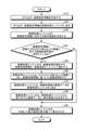
- FIG. 2 is a flowchart showing a display processing procedure of the display screen by the numerical control device according to the first embodiment. What is displayed in which area of the display 11 and how is determined by the CPU 22 on the control board 20 based on the state of the numerical control device 10A and the command from the operator.
- the CPU 22 creates image setting information indicating the determined content (step S10).
- the image setting information is information indicating what is displayed in which area and how.
- the CPU 22 sends the image setting information to the image processing engine 24 on the control board 20 (step S20).
- the image processing engine 24 creates a display screen corresponding to the image setting information (step S30). Further, the image processing engine 24 determines whether or not the image setting information includes the image processing content for the image captured from the video input IF 33 (step S40). That is, the image processing engine 24 determines whether or not the image processing content of the image processing engine 31 is included in the image setting information.
- the image processing engine 24 causes the display 11 to display the created display screen. (Step S90).
- the image processing engine 24 when the image setting information created by the CPU 22 includes the image processing content for the image captured from the video input IF 33 (step S40, Yes), the image processing engine 24 provides the image processing information indicating the image processing content. , Notify the image processing engine 31 (step S50). At this time, the image processing engine 24 notifies the image processing engine 31 of the image processing information via the inter-engine communication buses 26 and 38.
- the image processing function of the control board 20 creates request information indicating a request for image data, that is, image processing information, and the data communication function of the control board 20 transmits the image processing information to the function expansion board 30A. do.
- the data communication function of the function expansion board 30A receives the image processing information.
- the image processing engine 24 transmits the image setting information to the image processing engine 31, and the image processing engine 31 determines whether or not the image setting information includes the image processing content for the image captured from the video input IF 33. You may judge. In this case, the image processing engine 31 acquires the image processing information from the image setting information.
- the image processing information may include image size information.
- the image processing information includes, for example, the type of image processing (enlargement, reduction, rotation, cropping, image correction, composite display of multiple images), on / off timing of image processing, enlargement ratio, reduction ratio, rotation angle, and the like.
- Image correction includes color correction, luminance correction, distortion correction, and the like.
- the image processing engine 31 When the image processing engine 31 receives the image processing information, the image processing engine 31 performs image processing based on the image processing information on the image captured from the camera 12 via the video input IF 33 (step S60). Specifically, the image processing function of the function expansion board 30A creates image data (second image data) based on the image captured from the camera 12. Examples of image processing executed by the image processing engine 31 include enlargement, reduction, rotation, cutting, image correction, and composite display of a plurality of images of image data.
- the image processing engine 31 performs image processing according to the designated image processing information.
- the image processing engine 31 sends the image data after image processing to the image processing engine 24 (step S70). That is, the image data image-processed on the function expansion board 30A is transferred from the image processing engine 31 to the image processing engine 24 via the inter-engine communication buses 26 and 38.
- the data communication function of the function expansion board 30A transmits the image data to the control board 20, and the data communication function of the control board 20 receives the image data.
- the image processing engine 24 synthesizes the second image data received from the image processing engine 31 and the first image data which is a display screen corresponding to the image setting information (step S80). That is, the image processing engine 24 identifies the first image data, which is a display screen created by using the image setting information, which is the data on the control board 20, for the second image data received from the image processing engine 31. Create a display screen by pasting it at the position of.
- the display screen created by the image processing engine 24 using the data on the control board 20 is the first image data. Further, the image data created by the image processing engine 31 is the second image data. The display screen created by the image processing engine 24 by compositing is the third image data.
- the image processing engine 24 may include the data in the VRAM 25, the data in the memory 27, the state of the CPU 22, and the like in the third image data.
- the control board 20 can display the data in the VRAM 25, the data in the memory 27, the state of the CPU 22, and the like together with the data created by the image processing engine 31 on the display 11.
- the display screen created by the image processing engine 24 is output to the display 11 via the video output IF 23.
- the image processing engine 24 causes the display 11 to display the created display screen (step S90).
- the image processing engines 24 and 31 are connected by the inter-engine communication buses 26 and 38, and can read and write each other's setting registers. Therefore, the image processing engine 24 can make detailed image processing settings for the image processing engine 31 according to the image processing content on the function expansion board 30A included in the image setting information created by the CPU 22. That is, the image processing engine 24 can set the image processing by the image processing engine 31 in detail by writing the detailed settings of the image processing in the setting register of the image processing engine 31.
- the image captured from the video input IF 33 is not limited to the image data obtained by the camera 12, but may be an image image created by a personal computer or the like.
- the image processing engine 31 may apply a filter process to the captured image data.
- a trained model for detecting a human figure, a machine operator's face, a scratch on a workpiece, etc. is stored in advance, and an image is stored.
- the processing engine 31 detects a specific object in the image data by performing AI (Artificial Intelligence) inference processing using the trained model on the input of the captured image data. May be good.
- AI Artificial Intelligence
- the image processing engine 31 can detect, for example, the figure of a person, the face of an operator of a machine tool, scratches on a workpiece, and the like.
- the trained model is a model generated to detect a human figure, a machine tool operator's face, a scratch on a workpiece, etc. by so-called supervised learning according to a general neural network model, for example. It is generated on a device different from the numerical control device 10A or on a cloud server.
- the image processing engine 31 detects a specific object in the image data, for example, when there is a request from the image processing engine 24. In this case, when the image processing engine 24 detects a specific object, the image data of the detection result (image data of the face portion, image data of the scratched portion, etc.) and content information indicating the content of the image data are input. , Instruct the image processing engine 31 to send to the image processing engine 24.
- the content information is the operator's name or the like. Further, when the image processing engine 31 detects a scratch on the workpiece, the content information includes coordinates indicating the position of the scratch. Further, the content information may be information indicating that a specific object has been detected.
- the image processing engine 31 associates the image data with the content information and sends the image data to the image processing engine 24.
- the image processing engine 24 displays the content information on the screen of the display 11. Specifically, the image processing engine 24 creates a display screen in which content information is combined with a display screen in which image data is combined.
- the display screen including the content information created by the image processing engine 24 by synthesis is the fourth image data.
- the image processing engine 24 may display the information indicating that the specific object has been detected on the screen of the display 11 as character data. good. Further, the image processing engine 24 may store the detected image data of the object and the content information in the memory 27.
- the image processing engine 31 detects the figure of a person from the image data of the camera 12 and uses the image data of the person as image data.
- the image is transmitted to the image processing engine 24.
- the image processing engine 24 can notify the operator of a person in a blind spot that cannot be directly confirmed by the operator by displaying the image of the person on the display 11, so that the operator can be alerted to dangerous operations or the like. ..
- the image processing engine 31 detects the operator's face.
- the image processing engine 31 transmits an image of the operator's face as image data to the image processing engine 24, and the image processing engine 24 transmits the image data to the CPU 22.
- the CPU 22 transmits an instruction to issue an alarm to the image processing engine 24 when the same person has a long working time.
- the image processing engine 24 can instruct the display 11 to output a screen prompting the operator to take a break.
- the image processing engine 31 detects scratches on the workpiece.
- the image processing engine 31 transmits an image of scratches on the workpiece as image data to the image processing engine 24.
- the content information is coordinate position information indicating the position of a scratch on the workpiece.
- the image processing engine 24 causes the display 11 to display the image data of the scratches on the workpiece and the coordinate position information.
- the image processing engine 24 on the control board 20 is mounted on all the numerical control devices 10A as standard, it is desirable that the hardware is as inexpensive as possible, and it is desirable that the hardware be the minimum necessary. In this case, if the standard function of the image processing engine 24 is not sufficient and it is desired to display an image with appropriate image processing applied to an image input from the outside, the function expansion board 30A may be attached. ..
- the image processing engine 31 having an image processing function included in the hardware that can be retrofitted and the image processing engine 24 having an image processing function included in the main body can be bidirectionally and highly linked.
- the image processing engines 24 and 31 execute the cooperative operation, so that the image processing engine 24 moves from the image processing engine 31 to the camera 12. Get the image data of. Further, the image processing engine 24 creates a display screen corresponding to the image setting information and a display screen in which the image data of the camera 12 is combined and displays the display screen on the display 11.
- the numerical control device 10A displays the image data created by the function expansion board 30A on the display 11 using the image setting information created by the CPU 22, which is the data on the control board 20.
- the image setting information on the control board 20 side can be effectively used.
- the image data related to the image data created by the function expansion board 30A is created by the image processing engine 31, and the others are created by the image processing engine 24.
- the processing speed can be faster than creating image data using only one of the image processing engines.
- the function expansion board 30A has a configuration that can be retrofitted, it is not necessary to attach the function expansion board 30A when the function of the function expansion board 30A is unnecessary. Therefore, when only the standard function is required for the numerical control device 10A, the manufacturing cost of the numerical control device 10A can be reduced.
- the function expansion board 30A which is hardware that can be retrofitted, with other numerical control devices, the function expansion board 30A can be applied to other numerical control devices, so that the function expansion board 30A can be applied. Management costs can be reduced.
- the image processing engines 24 and 31 having the image processing function and the data communication function mutually execute data transfer, so that the CPU 22 is loaded. It does not take a long time and does not adversely affect the processing performance by the numerical control device 10A.
- Embodiment 2 Next, the second embodiment will be described with reference to FIGS. 3 and 4.
- the image processing engine of the function expansion board causes the display screen connected to the function expansion board to display the display screen.
- the function expansion board is attached to the function expansion slot 40 only when the processing by the function expansion board is required.
- FIG. 3 is a diagram showing a configuration of a numerical control system including the numerical control device according to the second embodiment.
- components that achieve the same functions as the numerical control system 1A of the first embodiment shown in FIG. 1 are designated by the same reference numerals, and duplicate description will be omitted.
- the numerical control system 1B includes a numerical control device 10B, an amplifier 3, and a motor 2.
- the numerical control device 10B includes a control board 20, a display 11, a function expansion board 30B, a camera 12, and a display 13.
- the display 13 is a second display.
- the function expansion board 30B has an image processing engine 31, a VRAM 32, a video input IF 33, and a video output IF 34.
- the video output IF 34 is connected to the display 13 and the image processing engine 31.
- the display device 13 is a display device similar to the display device 11.
- the function expansion board 30B is removable from the function expansion slot 40.
- FIG. 3 shows a state in which the function expansion board 30B is attached to the function expansion slot 40.
- the video output IF 23 is arranged on the control board 20, and the video output IF 34 is arranged on the function expansion board 30B.
- the numerical control device 10B can display an image on the two displays 11 and 13 at the same time.
- the display 13 may be an external device of the numerical control device 10B arranged outside the numerical control device 10B.
- FIG. 4 is a flowchart showing a display processing procedure of the display screen by the numerical control device according to the second embodiment. For the same processing as that described with reference to FIG. 2, duplicate description will be omitted.
- the CPU 22 on the control board 20 determines what and how to display in which area of the two indicators 11 and 13 based on the state of the numerical control device 10B and the command from the operator.
- the CPU 22 creates image setting information corresponding to the determined content (step S10).
- the CPU 22 sends the image setting information to the image processing engine 24 on the control board 20 (step S20).
- the image setting information includes identification information for identifying whether the image setting information is the image setting information for the image processing engine 24 or the image setting information for the image processing engine 31. This image setting information is data on the control board 20.
- the image processing engine 24 extracts the image setting information to the image processing engine 24 from the image setting information based on the identification information included in the image setting information.
- the image processing engine 24 creates a display screen by using the image setting information for the image processing engine 24 (step S110).
- the image processing engine 24 determines whether or not the image setting information of the image processing engine 31 is included in the image setting information based on the identification information included in the image setting information (step S120).
- the image processing engine 24 does not transmit the image setting information to the image processing engine 31. In this case, the image processing engine 24 causes the display 11 to display the display screen (step S160).
- the image processing engine 24 displays the image setting information for the image processing engine 31 as an image. It is transmitted to the processing engine 31 (step S130).
- the image processing engine 31 creates a display screen using the image setting information for the image processing engine 31 (step S140).
- the data on the display screen created by the image processing engine 31 is the fifth image data.
- the image processing engine 24 transmits the image setting information to the image processing engine 31, and the image processing engine 31 determines whether or not the image setting information includes the image setting information for the image processing engine 31. You may. In this case, the image processing engine 31 acquires the image processing information from the image setting information based on the identification information.
- the image processing engines 24 and 31 create the display screen based on the image setting information created by the CPU 22. Then, the image processing engine 31 causes the created display screen to be displayed on the display 13 (step S150), and the image processing engine 24 causes the created display screen to be displayed on the display 11 (step S160).
- the display screens created by the image processing engines 24 and 31 may or may not include an image captured by the camera 12.
- the timing at which the image processing engine 24 creates the display screen and the timing at which the image processing engine 31 creates the display screen may come first. Further, the timing at which the image processing engine 24 displays the display screen on the display 11 and the timing at which the image processing engine 31 displays the display screen on the display 13 may come first. That is, the image processing engine 24 may execute the processing of step S110 at any timing as long as it is after step S20 and before step S160. Further, the image processing engine 24 may execute the processing of step S160 at any timing as long as it is after step S110.
- the display screens displayed by the indicators 11 and 13 may be the same or different.
- the numerical control device 10B may control a large machine tool.
- the two indicators 11 and 13 are arranged apart from each other, and the indicators 11 and 13 display the same image, so that the operator is displayed on the indicators 11 and 13 from a wide range around the machine tool. You can see the information that is being displayed.
- the operator can obtain a lot of information at the same time by displaying different images on the indicators 11 and 13. Even when the two indicators 11 and 13 are arranged apart from each other, the information required by the operator may differ depending on the location. Further, when the video output IF 34 on the function expansion board 30B side outputs a large screen display screen that is easy to see even from a distance to the display 13 and displays it on the displays 11 and 13 with different screen resolutions. There is. In these cases, the numerical control device 10B can also display different display screens on the indicators 11 and 13.
- the image captured via the video input IF 33 provided on the function expansion board 30B is appropriately subjected to image processing by the image processing engine 31.
- the image data after the image processing is displayed on one or both of the displays 11 and 13 based on the image setting information created by the CPU 22.
- the image processing engine 31 sends the image data after image processing to the image processing engine 24 via the inter-engine communication buses 38 and 26.
- the image processing engine 24 causes the image data after image processing to be displayed in the specific area of the display 11.
- the image processing engine 31 causes the image data after image processing to be displayed in a specific area of the display device 13.
- the image processing engine 24 on the control board 20 is mounted on all the numerical control devices 10B as standard, so that it is desirable that the price is as low as possible and the minimum necessary. It is desirable to use the hardware of.
- the function expansion board 30B when it is desired to output the display screens to the two displays 11 and 13 at the same time, the function expansion board 30B may be attached, so that the cost of the hardware required as standard can be reduced. Further, even when it is desired to output the display screen to the two displays 11 and 13 at the same time, the image processing engines 24 and 31 both use the image setting information on the control board 20, so that the information on the main body side should be effectively utilized. Can be done.
- the image processing engine 31 on the optional function expansion board 30B side may have higher performance than the image processing engine 24, and the display 13 may have higher pixels or a larger screen than the display 11.
- the function expansion board 30B may be mounted in the function expansion slot 40 when it is desired to display the display on the display 13 having a high pixel count or a large screen, although the simultaneous output to the two screens is not performed.
- the function expansion board 30B includes all the components included in the function expansion board 30A, the function expansion board 30B may be made to perform the same processing as the function expansion board 30A.
- the image processing engine 24 in this case has a function of switching the processing to be executed by the image processing engine 31.
- the image processing engine 24 notifies the image processing engine 31 of which processing is to be executed, and then transmits the image processing information or the image setting information to the image processing engine 31.
- the image processing engine 24 when the image processing engine 24 requests the image data from the image processing engine 31, the image processing engine 24 notifies the image processing engine 31 that the image data is requested, and then the image processing information described in the first embodiment is used. It is sent to the image processing engine 31.
- the image processing engine 24 when the image processing engine 24 wants the image processing engine 31 to display the image data, the image processing engine 24 notifies the image processing engine 31 that the image data is to be displayed, and then the image setting information described in the second embodiment. Is sent to the image processing engine 31.
- control board 20 is provided with the video output IF 23, and the function expansion board 30B that can be retrofitted is provided with the video output IF 34. Therefore, the numerical control device 10B can display an image on the displays 11 and 13.
- Embodiment 3 Next, the third embodiment will be described with reference to FIGS. 5 and 6.
- a plurality of numerical control devices are connected, and each function expansion board shares information on each motor among the numerical control devices while maintaining temporal synchronization.
- the function expansion board is attached to the function expansion slot 40 only when the processing by the function expansion board is required.
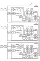
- FIG. 5 is a diagram showing a configuration of a numerical control system including the numerical control device according to the third embodiment.
- components that achieve the same functions as the numerical control system 1B of the second embodiment shown in FIG. 3 are designated by the same reference numerals, and duplicate description will be omitted.
- the numerical control system 1C includes a plurality of numerical control devices, a plurality of amplifiers, and a plurality of motors.
- a case where the numerical control system 1C includes three numerical control devices 10X, 10Y, 10Z, three amplifiers 3X, 3Y, 3Z, and three motors 2X, 2Y, 2Z will be described. do.
- the numerical control devices 10X to 10Z all have the same configuration. Further, the motors 2X to 2Z have the same configuration as the motor 2, and the amplifiers 3X to 3Z have the same configuration as the amplifier 3.
- the numerical control device 10X is connected to the numerical control devices 10Y and 10Z, and the numerical control device 10Y is connected to the numerical control device 10Z.
- the numerical control device 10X is connected to the amplifier 3X, and the amplifier 3X is connected to the motor 2X.
- the numerical control device 10Y is connected to the amplifier 3Y, and the amplifier 3Y is connected to the motor 2Y.
- the numerical control device 10Z is connected to the amplifier 3Z, and the amplifier 3Z is connected to the motor 2Z.
- the numerical control device 10X includes a control board 20, a display 11, a function expansion board 30C, a camera 12, and a display 13.
- the function expansion board 30C includes an image processing engine 31, a data communication engine 35 which is a data communication unit, a VRAM 32, a video input IF 33, a video output IF 34, and inter-device communication IFs 36 and 37.
- the image processing engine 31 of the function expansion board 30C does not have to have an image processing function.
- the function expansion board 30C may not include the VRAM 32, the video input IF 33, and the video output IF 34.
- the image processing engine 24 of the control board 20 does not have to have an image processing function.
- the control board 20 does not have to include the video output IF 23 and the VRAM 25.
- the image processing engine 31 When the image processing engine 31 does not have an image processing function, the image processing engine 31 is an internal communication engine that executes communication with the control board 20. When the image processing engine 24 does not have an image processing function, the image processing engine 24 is an internal communication engine that executes communication with the function expansion board 30C.
- the image processing engine 24 is the first processing engine, which is the first processing unit, and the image processing engine 31 and the data communication engine 35 are the second processing engines, which are the second processing units. ..
- the data communication engine 35 is also built in the semiconductor chip in which the image processing engine 31 of the function expansion board 30C is built. Adding the data communication engine 35 in the semiconductor chip can be easily realized if the circuit capacity of the semiconductor chip is sufficient.
- the data communication engine 35 has a data communication function and a data processing function for performing high-speed communication between the numerical control devices 10X to 10Z. That is, the data communication engine 35 executes communication with an external device. Examples of data communication functions include DMA (Direct Memory Access) function, data buffering function, and SerDes (serializer, deserializer) function.
- the data communication function of the data communication engine 35 is the third data communication function.
- Examples of data processing are 8B10B conversion processing, bit error detection processing, bit error correction processing, and the like.
- Data transfer is performed between the numerical control device 10X and the numerical control device 10Y via the inter-device communication IF 37 included in the numerical control device 10X and the inter-device communication IF 36 included in the numerical control device 10Y.
- data transfer is performed between the numerical control device 10Y and the numerical control device 10Z via the inter-device communication IF 37 included in the numerical control device 10Y and the inter-device communication IF 36 included in the numerical control device 10Z.
- data transfer is performed between the numerical control device 10Z and the numerical control device 10X via the inter-device communication IF 37 included in the numerical control device 10Z and the inter-device communication IF 36 included in the numerical control device 10X.
- the inter-device communication IFs 36 and 37 are connected to a semiconductor chip containing an image processing engine 31 and a data communication engine 35.
- the network topology of the network consisting of the three numerical control devices 10X to 10Z is a ring type and a full connect type, but the network topology may be a line type or a mesh type.
- the numerical control device included in the numerical control system 1C may be two or four or more.
- one of the main functions of the CPU included in the numerical control device is the motor control function. It is possible to control a plurality of motors by the CPU of one numerical control device, but the upper limit of the number of motors that can be controlled by one numerical control device is determined depending on the performance of the mounted CPU.
- each numerical control device 10X uses the data communication engine 35 to perform high-speed communication with the numerical control devices 10Y and 10Z, thereby synchronizing the motors 2X to 2Z.
- Each motor information is shared between the numerical control devices 10X to 10Z.
- the numerical control device 10X uses a timer (not shown) mounted on the control board 20 or the function expansion board 30C to generate a reference timing signal having a fixed cycle.
- the numerical control device that generates the reference timing signal may be the numerical control device 10Y or the numerical control device 10Z.
- any one of the numerical control devices 10X to 10Z becomes the master numerical control device, and the master numerical control device generates a reference timing signal.
- the numerical control device of the master is specified by the user in advance.
- the control board 20 or the function expansion board 30C always counts the number of pulses output from the timer by the same number, and outputs a signal at the time of counting to generate a reference timing signal having a fixed cycle.
- the control board 20 or the function expansion board 30C resets the counter to 0 after counting a specific number of pulses.
- the image processing engine 31 and the data communication engine 35 of the numerical control device 10X output a synchronization signal to the image processing engine 31 and the data communication engine 35 of the numerical control device 10Y in synchronization with the reference timing signal. Similar to the numerical control device 10X, the image processing engine 31 and the data communication engine 35 of the numerical control device 10Y also count the pulses of the timer mounted inside, and transmit the synchronization signal output from the numerical control device 10X. The counter is reset to 0 at the timing of reception. In the numerical control devices 10X and 10Y, the image processing engine 31 and the data communication engine 35 operate according to the synchronization signal. Therefore, the data communication engine 35 of the numerical control device 10X transmits / receives motor information to / from the numerical control device 10Y based on the synchronization signal.
- the numerical control device 10X and the numerical control device 10Z can be synchronized by the same processing as between the numerical control device 10X and the numerical control device 10Y. This makes it possible to ensure temporal synchronization between the plurality of numerical control devices 10X to 10Z.
- All the numerical control devices 10X to 10Z are provided with a storage area for each motor information in the shared memory on the control board 20.
- the shared memory may be a RAM in a chip for storing the image processing engine 24, or may be another memory.
- the storage area for each motor information is referred to as a motor information storage area.
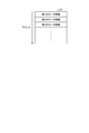
- FIG. 6 is a diagram for explaining a motor information storage area provided in the numerical control device according to the third embodiment.
- the numerical control devices 10X to 10Z each have a motor information storage area 101 in a shared memory. Motor information is stored in the motor information storage area 101. In the numerical control devices 10X to 10Z, it is specified in which area in the motor information storage area 101 the motor information of which numerical control device is stored.
- the storage area for motor information is defined by an address in the shared memory.
- the motor information storage area 101 is an area in which the motor information acquired from the motor 2X (hereinafter referred to as the first motor information) is stored, and an area in which the motor information acquired from the motor 2Y is stored (hereinafter referred to as the first motor information). It includes an area in which the second motor information) and the motor information acquired from the motor 2Z (hereinafter referred to as the third motor information) are stored.
- the first to third motor information may be referred to as motor information.
- the motor information of one of the first to third motor information is the first device information, and the other motor information of the first to third motor information is the second device information. be.
- the area in which the first motor information is stored is associated with the identification information of the first motor information.
- the area where the second motor information is stored and the identification information of the second motor information are associated with each other, and the area where the third motor information is stored. , Is associated with the identification information of the third motor information.
- the numerical control devices 10X to 10Z store the first to third motor information in the motor information storage area 101 according to these identification information.
- the address used by the numerical control device 10X is the same as the address used by the numerical control devices 10Y and 10Z. That is, the address in which the motor information acquired by the numerical control device 10X from the motor 2X is stored is common to the numerical control devices 10X to 10Z. Similarly, the address where the motor information acquired by the numerical control device 10Y from the motor 2Y is stored is common to the numerical control devices 10X to 10Z, and the address where the motor information acquired by the numerical control device 10Z from the motor 2Z is stored. Is common to the numerical control devices 10X to 10Z.
- the motor information storage areas 101 of the numerical control devices 10X to 10Z have the same contents.
- the numerical control device 10X stores the first motor information acquired from the motor 2X in the motor information storage area 101 of the numerical control device 10X. In this case, the numerical control device 10X stores the first motor information in the area associated with the first motor information, that is, the address associated with the first motor information.
- the numerical control device 10Y stores the second motor information acquired from the motor 2Y in the motor information storage area 101 of the numerical control device 10Y.
- the numerical control device 10Y stores the second motor information in the area associated with the second motor information, that is, the address associated with the second motor information.
- the numerical control device 10Z stores the third motor information acquired from the motor 2Z in the motor information storage area 101 of the numerical control device 10Z.
- the numerical control device 10Z stores the third motor information in the area associated with the third motor information, that is, the address associated with the third motor information.
- the numerical control device 10X stores the second and third motor information acquired from the numerical control devices 10Y and 10Z in the motor information storage area 101 of the numerical control device 10X.
- the numerical control device 10Y stores the first and third motor information acquired from the numerical control devices 10X and 10Z in the motor information storage area 101 of the numerical control device 10Y.
- the numerical control device 10Z stores the first and second motor information acquired from the numerical control devices 10X and 10Y in the motor information storage area 101 of the numerical control device 10Z.
- the motor information storage areas 101 of the numerical control devices 10X to 10Z have the same contents.
- the CPU 22 of the numerical control device 10X updates the first motor information of the motor 2X that it controls every control cycle.
- the CPU 22 of the numerical control device 10Y updates the second motor information of the motor 2Y controlled by itself for each control cycle
- the CPU 22 of the numerical control device 10Z is the motor 2Z controlled by itself.
- the third motor information is updated every control cycle.
- the image processing engine 24 of the numerical control device 10X uses the identification information (hereinafter referred to as the first motor identification information) of the first motor information updated by the CPU 22 with the image processing engine 31 of the numerical control device 10X and data communication. Notify the engine 35.
- the image processing engine 31 and the data communication engine 35 may be referred to as an engine unit.
- the image processing engine 24 of the numerical control device 10Y notifies the engine unit of the numerical control device 10Y of the identification information (hereinafter referred to as the second motor identification information) of the second motor information updated by the CPU 22.
- the image processing engine 24 of the numerical control device 10Z notifies the engine unit of the numerical control device 10Z of the identification information (hereinafter referred to as the third motor identification information) of the third motor information updated by the CPU 22.
- the first to third motor identification information may be referred to as motor identification information.
- the engine unit of the numerical control device 10X reads the first motor information corresponding to the notified first motor identification information from the motor information storage area 101 stored in the shared memory of the control board 20.
- the data communication engine 35 transmits the motor correspondence information in which the read first motor information and the first motor identification information are associated with each other to the engine unit of the numerical control devices 10Y and 10Z.
- the engine unit of the numerical control device 10Y Similar to the engine unit of the numerical control device 10X, the engine unit of the numerical control device 10Y also provides the motor correspondence information in which the second motor information and the second motor identification information are associated with each other, and the engine of the numerical control devices 10X and 10Z. Send to the department.
- the engine unit of the numerical control device 10Z Similar to the engine unit of the numerical control device 10X, the engine unit of the numerical control device 10Z also provides the motor correspondence information in which the third motor information and the third motor identification information are associated with each other, and the engine of the numerical control devices 10X and 10Y. Send to the department.
- the engine unit of the numerical control device 10X stores the received second motor information in the area of the motor information storage area 101 in which the second motor information is stored. Overwrite.
- the engine unit of the numerical control device 10X receives the third motor in the area where the third motor information is stored in the motor information storage area 101 based on the received third motor identification information. Overwrite the information.
- the numerical control device 10Y also overwrites the received first motor information in the area where the first motor information is stored based on the received first motor identification information. .. Further, the numerical control device 10Y overwrites the received third motor information in the area where the third motor information is stored, based on the received third motor identification information.
- the numerical control device 10Z also overwrites the received first motor information in the area where the first motor information is stored based on the received first motor identification information. .. Further, the numerical control device 10Z overwrites the received second motor information in the area where the second motor information is stored based on the received second motor identification information.
- the numerical control system 1C controls a process of acquiring motor information, a process of notifying another numerical control device of the correspondence between the motor identification information and the motor information, a process of updating the motor information, and a process of overwriting the motor information. Repeat every cycle.
- the numerical control devices 10X to 10Z can take over and control the motor controlled by the CPU 22 of the other numerical control devices from a certain control cycle or later.
- the numerical control devices 10X to 10Z control the motors 2X to 2Z based on the first to third motor information stored in the motor information storage area 101.
- the numerical control devices 10X to 10Z use the data communication engine 35 to transmit a command signal for motor control to another numerical control device.
- the other numerical control device receives the command signal for motor control, the other numerical control device transmits the command signal for motor control to the amplifier.
- the CPU 22 of the numerical control device 10X when the numerical control device 10X controls the motor 2Y, the CPU 22 of the numerical control device 10X generates a command signal for controlling the motor 2Y.
- This command signal is sent to the data communication engine 35 via the image processing engine 24 and the inter-engine communication buses 26 and 38 in the numerical control device 10X. Then, the data communication engine 35 transmits a command signal for controlling the motor 2Y from the inter-device communication IF 37 to the inter-device communication IF 36 of the numerical control device 10Y.
- the data communication engine 35 receives a command signal for controlling the motor 2Y from the inter-device communication IF36.
- the data communication engine 35 sends a command signal for controlling the motor 2Y to the CPU 22 via the inter-engine communication buses 38 and 26 and the image processing engine 24.
- the CPU 22 transmits a command signal for controlling the motor 2Y from the motor control communication IF 21 to the amplifier 3Y, and the amplifier 3Y drives the motor 2Y according to the command signal for controlling the motor 2Y.
- the transmission / reception of the command signal between the numerical control devices 10X to 10Z is executed by using the data communication engine 35.
- the CPU or image processing engine on the control board can secure temporal synchronization and share motor information in communication between a plurality of numerical control devices.
- the control board becomes expensive. Since the CPU and image processing engine on the control board are installed as standard in all numerical control devices, it is desirable that they are as inexpensive as possible, and it is desirable that the hardware be the minimum necessary.
- the function expansion board 30C may be attached, so that the cost of hardware required as standard can be reduced.
- the function expansion board 30C may be made to perform the same processing as the function expansion boards 30A and 30B.
- the image processing engine 24 in this case has a function of switching the processing to be executed by the engine unit.
- the image processing engine 24 notifies the engine unit of which processing is to be executed, and then transmits image processing information, image setting information, or motor correspondence information to the engine unit.
- the image processing engine 24 when the image processing engine 24 requests the image data from the engine unit, the image processing engine 24 notifies the engine unit that the image data is requested, and then sends the image processing information described in the first embodiment to the engine unit. ..
- the image processing engine 24 when the image processing engine 24 wants to display the image data on the engine unit, the image processing engine 24 notifies the engine unit that the image data is to be displayed, and then transmits the image setting information described in the second embodiment to the engine unit. send.
- the image processing engine 24 wants the engine unit to transmit the motor correspondence information to the outside, the image processing engine 24 notifies the engine unit to transmit the motor correspondence information to the outside, and then the motor identification information described in the third embodiment. To the engine section. As a result, the engine unit reads the motor information from the control board 20 based on the motor identification information, and sends the motor correspondence information to the numerical control devices 10Y and 10Z.
- the function expansion board 30C that can be retrofitted includes the data communication engine 35.
- the numerical control devices 10X to 10Z can execute data communication with each other, so that the function expansion boards 30C can secure the temporal synchronization and the motors 2X to 2Z between the numerical control devices 10X to 10Z. Motor information can be shared. Therefore, the numerical control devices 10X to 10Z can control any of the motors 2X to 2Z.
- the configuration shown in the above embodiments is an example, and can be combined with another known technique, can be combined with each other, and does not deviate from the gist. It is also possible to omit or change a part of the configuration.
- 1A-1C numerical control system 2,2X-2Z motor, 3,3X-3Z amplifier, 10A, 10B, 10X-10Z numerical control device, 11,13 display, 12 camera, 20 control board, 21 motor control communication IF , 22 CPU, 23,34 video output IF, 24,31 image processing engine, 25,32 VRAM, 26,38 engine-to-engine communication bus, 27 memory, 30A-30C function expansion board, 33 video input IF, 35 data communication engine , 36, 37 Inter-device communication IF, 40 Function expansion slot, 101 Motor information storage area.
Landscapes
- Engineering & Computer Science (AREA)
- Human Computer Interaction (AREA)
- Manufacturing & Machinery (AREA)
- Physics & Mathematics (AREA)
- General Physics & Mathematics (AREA)
- Automation & Control Theory (AREA)
- Numerical Control (AREA)
Abstract
数値制御装置(10A)が、モータ(2)の制御機能、第1の画像データを作成する機能、および第1のデータ通信機能を備えた画像処理エンジン(24)を具備する制御基板(20)と、カメラ(12)で撮像された画像から第2の画像データを作成する機能、および第2のデータ通信機能を備えた画像処理エンジン(31)を具備するとともに制御基板(20)に着脱可能な機能拡張基板(30A)と、を有し、第1の画像処理機能は、制御基板上のデータを用いて第1の画像データを作成し、第1および第2のデータ通信機能は、機能拡張基板(30A)と制御基板(20)との間で通信を実行する機能であり、機能拡張基板(30A)が制御基板(20)に取り付けられると、画像処理エンジン(24)が、画像処理エンジン(31)から第2の画像データを取得し、第1の画像データおよび第2の画像データを用いて表示画面を作成し表示器(11)に表示させる。
Description
本開示は、画像処理機能を備えた数値制御装置および数値制御システムに関する。
後付け可能なハードウェアによって機能を向上させる数値制御装置がある。例えば、特許文献1に記載の数値制御装置は、表示機能および操作機能を向上させる場合に、制御基板の全体を交換する必要がないように、表示機能および操作機能を有するパソコン機能カードといった後付け可能なハードウェアを本体に取り付けている。この特許文献1に記載の数値制御装置は、後付け可能なハードウェアを交換することで、表示機能および操作機能を向上させている。
しかしながら、上記特許文献1の技術では、後付け可能なハードウェアに含まれる、プロセッサおよびグラフィック制御回路が映像データを生成し、本体側へ一方向に送信しているに過ぎない。このため、上記特許文献1の技術では、表示に必要な本体側の情報を有効活用できないという問題があった。
本開示は、上記に鑑みてなされたものであって、後付け可能なハードウェアから取得した画像を表示する場合において、本体側の情報を有効活用する数値制御装置を得ることを目的とする。
上述した課題を解決し、目的を達成するために、本開示の数値制御装置は、第1の被制御機器を制御する制御機能、第1の表示器による表示画面の表示に用いられる第1の画像データを作成する第1の画像処理機能、および第1のデータ通信機能を備えた第1の画像処理部を具備する制御基板を有する。また、本開示の数値制御装置は、撮像装置で撮像された画像から表示に用いられる第2の画像データを作成する第2の画像処理機能、および第2のデータ通信機能を備えた第2の画像処理部を具備するとともに制御基板に着脱可能な拡張基板を有する。第1の画像処理機能は、制御基板上のデータを用いて第1の画像データを作成する。第1のデータ通信機能は、拡張基板との間で通信を実行する機能であり、第2のデータ通信機能は、制御基板との間で通信を実行する機能である。拡張基板が制御基板に取り付けられると、第1の画像処理部が、第2の画像処理部から第2の画像データを取得し、第1の画像データおよび第2の画像データを用いて表示画面を作成し第1の表示器に表示させる。
本開示にかかる数値制御装置は、後付け可能なハードウェアから取得した画像を表示する場合において、本体側の情報を有効活用することができるという効果を奏する。
以下に、本開示の実施の形態にかかる数値制御装置および数値制御システムを図面に基づいて詳細に説明する。
実施の形態1.
図1は、実施の形態1にかかる数値制御装置を備えた数値制御システムの構成を示す図である。数値制御システム1Aは、数値制御装置10Aと、アンプ3と、モータ2とを備えている。数値制御装置10Aは、制御基板20と、表示器11と、機能拡張基板30Aと、カメラ12とを備えている。
図1は、実施の形態1にかかる数値制御装置を備えた数値制御システムの構成を示す図である。数値制御システム1Aは、数値制御装置10Aと、アンプ3と、モータ2とを備えている。数値制御装置10Aは、制御基板20と、表示器11と、機能拡張基板30Aと、カメラ12とを備えている。
制御基板20は、数値制御装置10Aの本体に配置される基板である。制御基板20は、第1の被制御機器であるモータ2を制御する制御機能を有している。制御基板20は、モータ制御通信IF(InterFace、インタフェース)21と、CPU(Central Processing Unit、中央処理装置、処理装置、演算装置、マイクロプロセッサ、マイクロコンピュータ、DSP(Digital Signal Processor)ともいう)22と、映像出力IF23と、画像処理エンジン24と、VRAM(Video Random Access Memory、ビデオメモリ)25と、エンジン間通信バス26と、メモリ27と、機能拡張スロット40とを有している。機能を拡張するための拡張基板である機能拡張基板30Aは、画像処理エンジン31と、VRAM32と、映像入力IF33と、エンジン間通信バス38とを有している。
モータ制御通信IF21は、アンプ3に接続されており、アンプ3はモータ2に接続されている。モータ制御通信IF21は、アンプ3との間で通信を実行する。
映像出力IF23は、表示器11に接続されている。機能拡張基板30Aは、機能拡張スロット40に着脱可能となっている。図1では、機能拡張スロット40に機能拡張基板30Aが取り付けられた状態を示している。
CPU22は、数値制御装置10Aの全体を制御する。また、CPU22は、例えば、モータ2を制御する。CPU22は、モータ制御通信IF21を介して、アンプ3にモータ制御用の指令信号、すなわち制御信号を送信する。アンプ3は、CPU22から受信した指令信号に従ってモータ2を駆動する。
また、CPU22は、アンプ3およびモータ制御通信IF21を介して、モータ2からのフィードバック信号を受信し、モータ2のフィードバック制御を実行する。なお、図1にはアンプ3およびモータ2がそれぞれ1つずつしか図示されていないが、数値制御装置10Aには、複数のアンプ3および複数のモータ2が接続されていてもよい。この場合、CPU22は、複数台のモータ2を制御する。
また、制御基板20は、CPU22の代わりにシステムLSI(Large Scale Integration)を有していてもよい。メモリ27の例は、RAM、ROM(Read Only Memory)である。メモリ27は、CPU22が各種処理を実行する際の一時メモリに使用される。
数値制御装置10Aは、ユーザに対して数値制御装置10Aの情報を表示するための表示器11を備えている。表示器11が、第1の表示器である。数値制御装置10Aの情報は、数値制御装置10Aによるモータ2の制御状態、モータ2への設定内容などである。この表示器11の表示内容を見ることで、ユーザは数値制御装置10Aの状態を把握することができる。
また、図示省略しているが、表示器11の近くには、キースイッチが配置されている。数値制御装置10Aでは、ユーザによって、キースイッチまたは表示器11に表示されているソフトウェアキーが押下されることにより、数値制御装置10Aへの設定、加工プログラムの作成などが実行される。
画像処理エンジン24は、画像処理を高速に処理するためのハードウェア回路であり、画像処理部としての機能を備えている。第1の画像処理部である画像処理エンジン24は、モータ2の状態を表示器11に表示させる画像の画像データを作成する画像処理機能、およびデータ通信機能を備えている。画像処理エンジン24が備えるデータ通信機能は、機能拡張基板30Aとの間でデータ通信を実行する機能である。画像処理エンジン24の画像処理機能が、第1の画像処理機能であり、画像処理エンジン24のデータ通信機能が、第1のデータ通信機能である。画像処理エンジン24が備える第1の画像処理機能は、表示器11による表示画面の表示に用いられるデータを作成するとともに、このデータを用いて表示に用いられる第1の画像データを作成する機能である。
画像処理エンジン24は、制御基板20上のデータを用いて表示器11が表示する画像の画像データを作成する。制御基板20上のデータは、例えばCPU22が作成したデータ、CPU22内のデータ、VRAM25内のデータ、またはメモリ27内のデータである。表示器11が表示する画像は、画像処理エンジン31が作成した画像である第2の画像データと、画像処理エンジン24が作成した第1の画像データとの少なくとも一方を用いた画像である。画像処理エンジン24は、CPU22の処理負荷を軽減するために、CPU22とは別の回路となっている。なお、表示器11が表示する画像の画像データは、CPU22が作成してもよい。
画像処理エンジン24は、大規模集積回路(LSI)、FPGA(Field Programmable Gate Array)などの半導体チップによって実現される。画像処理エンジン24は、作成した画像データを、映像出力IF23を介して表示器11に出力する。
VRAM25は、画像処理エンジン24に接続されている。VRAM25は、表示器11に表示する画像データを一時的に保持するメモリである。エンジン間通信バス26は、画像処理エンジン24と機能拡張スロット40とを接続する。エンジン間通信バス26は、双方向の通信が可能なバスである。エンジン間通信バス26は、画像処理エンジン24から送られてくる情報を画像処理エンジン31に送り、画像処理エンジン31から送られてくる情報を画像処理エンジン24に送る。
機能拡張スロット40は、後付けで機能拡張基板30Aに取り付け可能となっている。すなわち、ユーザは、機能拡張スロット40に機能拡張基板30Aを挿入することで、制御基板20に、機能拡張基板30Aが有する機能を追加することができる。実施の形態1では、映像入力IF33と画像処理エンジン31とが搭載されている機能拡張基板30Aが機能拡張スロット40に挿入される場合について説明する。
画像処理エンジン31は、画像処理を高速に処理するためのハードウェア回路であり、画像処理部としての機能を備えている。第2の画像処理部である画像処理エンジン31は、カメラ12で撮像された画像から表示器11での表示に用いられる画像の画像データを作成する画像処理機能、およびデータ通信機能を備えている。画像処理エンジン31が備えるデータ通信機能は、制御基板20との間でデータ通信を実行する機能である。画像処理エンジン31の画像処理機能が、第2の画像処理機能であり、画像処理エンジン31のデータ通信機能が、第2のデータ通信機能である。
画像処理エンジン31は、画像処理エンジン24と同様に、大規模集積回路、FPGAなどの半導体チップによって実現される。画像処理エンジン31は、表示器11が表示する画像の画像データを作成する。画像処理エンジン31は、画像処理エンジン24からの指示に従って、画像データを作成する。画像処理エンジン31は、作成した画像データを、画像処理エンジン24に送る。
VRAM32は、画像処理エンジン31に接続されている。VRAM32は、画像処理エンジン31が作成した画像データを一時的に保持するメモリである。エンジン間通信バス38は、画像処理エンジン31と機能拡張スロット40とを接続する。エンジン間通信バス38は、双方向の通信が可能なバスである。エンジン間通信バス38は、画像処理エンジン24から送られてくる情報を画像処理エンジン31に送り、画像処理エンジン31から送られてくる情報を画像処理エンジン24に送る。
映像入力IF33は、カメラ12といった撮像装置、および画像処理エンジン31に接続されている。映像入力IF33は、カメラ12が撮像した画像の画像データを受け付けて画像処理エンジン31に送る。なお、カメラ12は、映像を撮像してもよい。この場合、映像入力IF33は、カメラ12が撮像した映像の映像データを受け付けて画像処理エンジン31に送る。
制御基板20は、CPU22が、メモリ27で記憶されている制御基板20の動作を実行するための、制御プログラムを読み出して実行することにより実現される。制御プログラムは、制御基板20の動作を実行するためのコンピュータで実行可能なプログラムである。制御プログラムは、制御基板20の手順または方法をコンピュータに実行させるものであるともいえる。
制御基板20で実行される制御プログラムは、制御処理を実行する制御部を含むモジュール構成となっており、制御部が主記憶装置上にロードされ、制御部が主記憶装置上に生成される。
制御プログラムは、インストール可能な形式または実行可能な形式のファイルで、コンピュータが読み取り可能な記憶媒体に格納されてコンピュータプログラムプロダクトとして提供されてもよい。また、制御プログラムは、インターネットなどのネットワーク経由で数値制御装置10Aに提供されてもよい。なお、制御基板20の機能について、一部を専用回路などの専用のハードウェアで実現し、一部をソフトウェアまたはファームウェアで実現するようにしてもよい。
機能拡張基板30Aが機能拡張スロット40に挿入されると、機能拡張基板30A上の画像処理エンジン31と、制御基板20上の画像処理エンジン24とが、エンジン間通信バス26,38を介して繋がる。これにより、画像処理エンジン24,31間では、双方向にデータを転送すること、互いのレジスタにアクセスすることなどが可能となる。また、画像処理エンジン24,31は、処理の種類を指定するパラメータの設定、処理に必要なパラメータの設定、および処理開始タイミングの制御を相互に行うことが可能となる。
エンジン間通信バス26,38は、シリアルバスであってもよいし、パラレルバスであってもよい。数値制御装置10Aでは、2つの画像処理エンジン24,31がエンジン間通信バス26,38で接続されているので、数値制御装置10Aは、時間的に同期をとりながら画像処理エンジン24,31間で協調動作を実行することができる。
2つの画像処理エンジンのそれぞれに設定レジスタを持たせた場合、両者に対してレジスタの設定を行う必要があるので設定に時間がかかり、また両者の同期を取りにくいという問題があった。これに対し、実施の形態1では、画像処理エンジン24,31の何れか一方がレジスタ設定を行うだけで、エンジン間通信バス26,38を通じて画像処理エンジン24,31間が同期されるので、画像処理エンジン24,31の両方にレジスタが設定される。これにより、数値制御装置10Aは、レジスタ設定の時間を削減でき、設定切替に伴うオーバーヘッドも削減できる。
また、数値制御装置10Aは、画像処理エンジン24,31がエンジン間通信バス26,38で接続されているので、画像処理エンジン31に画像が入力されてから実際に表示器11に表示されるまでの遅延時間、オペレータといったユーザが操作入力を実行してからの反応時間を小さくすることができる。
また、2つの画像処理エンジン24,31のそれぞれに搭載されている画像処理機能は、共通の機能もあるが異なる画像処理機能が含まれていてもよく、それぞれが補完し合うように動作することも可能である。
なお、表示器11およびカメラ12の少なくとも一方は、数値制御装置10Aの外部に配置された数値制御装置10Aの外部機器であってもよい。
つぎに、数値制御装置10Aの動作について説明する。図2は、実施の形態1にかかる数値制御装置による表示画面の表示処理手順を示すフローチャートである。表示器11の何れの領域に何をどのように表示するかは、数値制御装置10Aの状態およびオペレータからの指令に基づいて、制御基板20上のCPU22が決定する。CPU22は、決定した内容を示す画像設定情報を作成する(ステップS10)。画像設定情報は、何れの領域に何をどのように表示するかを示す情報である。CPU22は、画像設定情報を制御基板20上の画像処理エンジン24に送る(ステップS20)。
画像処理エンジン24は、画像設定情報に対応する表示画面を作成する(ステップS30)。また、画像処理エンジン24は、画像設定情報に、映像入力IF33から取り込んだ画像に対する画像処理内容が含まれているか否かを判定する(ステップS40)。すなわち、画像処理エンジン24は、画像設定情報に、画像処理エンジン31による画像処理内容が含まれているか否かを判定する。
CPU22が作成した画像設定情報に、映像入力IF33から取り込んだ画像に対する画像処理内容が含まれていない場合(ステップS40、No)、画像処理エンジン24は、作成した表示画面を表示器11に表示させる(ステップS90)。
一方、CPU22が作成した画像設定情報に、映像入力IF33から取り込んだ画像に対する画像処理内容が含まれている場合(ステップS40、Yes)、画像処理エンジン24は、画像処理内容を示す画像処理情報を、画像処理エンジン31に通知する(ステップS50)。このとき、画像処理エンジン24は、エンジン間通信バス26,38を介して、画像処理情報を画像処理エンジン31に通知する。
具体的には、制御基板20の画像処理機能が、画像データの要求を示す要求情報、すなわち画像処理情報を作成し、制御基板20のデータ通信機能が、画像処理情報を機能拡張基板30Aに送信する。これにより、機能拡張基板30Aのデータ通信機能が画像処理情報を受信する。
なお、画像処理エンジン24は、画像設定情報を画像処理エンジン31に送信し、画像処理エンジン31が、画像設定情報に、映像入力IF33から取り込んだ画像に対する画像処理内容が含まれているか否かを判定してもよい。この場合、画像処理エンジン31が、画像設定情報から画像処理情報を取得することとなる。なお、画像処理情報には、画像サイズの情報が含まれていてもよい。
画像処理情報には、例えば、画像処理の種類(拡大、縮小、回転、切り出し、画像の補正、複数画像の合成表示)、画像処理のオンおよびオフのタイミング、拡大率、縮小率、回転角度、切り出す画像の座標等が含まれている。画像の補正には、色の補正、輝度の補正、歪みの補正などが含まれている。
画像処理エンジン31は、画像処理情報を受け付けると、映像入力IF33を介してカメラ12から取り込んだ画像に対し、画像処理情報に基づいた画像処理を行う(ステップS60)。具体的には、機能拡張基板30Aの画像処理機能が、カメラ12から取り込んだ画像に基づいて、画像データ(第2の画像データ)を作成する。画像処理エンジン31が実行する画像処理の例としては、画像データの拡大、縮小、回転、切り出し、画像の補正、複数画像の合成表示などである。
このように、画像処理エンジン31は、指定された画像処理情報に従って画像処理を行う。画像処理エンジン31は、画像処理後の画像データを画像処理エンジン24に送る(ステップS70)。すなわち、機能拡張基板30A上で画像処理された画像データは、画像処理エンジン31から、エンジン間通信バス26,38を経由して、画像処理エンジン24に転送される。具体的には、機能拡張基板30Aのデータ通信機能が、画像データを制御基板20に送信し、制御基板20のデータ通信機能が画像データを受信する。
画像処理エンジン24は、画像処理エンジン31から受け付けた第2の画像データと、画像設定情報に対応する表示画面である第1の画像データとを合成する(ステップS80)。すなわち、画像処理エンジン24は、画像処理エンジン31から受け付けた第2の画像データを、制御基板20上のデータである画像設定情報を用いて作成された表示画面である第1の画像データの特定の位置に貼り付けることで、表示画面を作成する。
制御基板20上のデータを用いて画像処理エンジン24が作成した表示画面が第1の画像データである。また、画像処理エンジン31が作成した画像データが第2の画像データである。画像処理エンジン24が合成によって作成した表示画面が第3の画像データである。
なお、画像処理エンジン24は、第3の画像データに、VRAM25内のデータや、メモリ27内のデータや、CPU22の状態等を含めてもよい。その場合には、制御基板20は、表示器11に画像処理エンジン31の作成したデータと合わせて、VRAM25内のデータや、メモリ27内のデータや、CPU22の状態等を表示させることができる。
画像処理エンジン24によって作成された表示画面は、映像出力IF23を介して表示器11に出力される。これにより、画像処理エンジン24は、作成した表示画面を表示器11に表示させる(ステップS90)。
ここで、画像処理エンジン24,31はエンジン間通信バス26,38で繋がっており、互いの設定レジスタを読み書きすることができる。したがって、画像処理エンジン24は、CPU22が作成した画像設定情報に含まれる機能拡張基板30A上の画像処理内容に従い、画像処理エンジン31に対して、画像処理の詳細設定を行うことが可能である。すなわち、画像処理エンジン24は、画像処理エンジン31の設定レジスタに画像処理の詳細設定を書き込むことによって、画像処理エンジン31による画像処理を詳細に設定することができる。なお、映像入力IF33から取り込む画像は、カメラ12による画像データに限らず、パーソナルコンピュータ等で作成された画像イメージであってもよい。
また、画像処理エンジン31は、取り込んだ画像データにフィルタ処理を施してもよい。さらに、画像処理エンジン31の内蔵メモリまたはVRAM32に、例えば、人の姿、工作機械のオペレータの顔、加工物に付いた傷などを検出するための学習済モデルを事前に格納しておき、画像処理エンジン31が、取り込んだ画像データの入力に対して、前記学習済モデルを用いたAI(Artificial Intelligence、人工知能)推論処理を施すことによって、画像データの中の特定の対象物を検出してもよい。この場合、画像処理エンジン31は、例えば、人の姿、工作機械のオペレータの顔、加工物に付いた傷などを検出することが可能となる。ここで学習済モデルは、例えば、一般的なニューラルネットワークモデルに従って、いわゆる教師あり学習により、人の姿、工作機械のオペレータの顔、加工物に付いた傷などを検出するように生成されたモデルであり、数値制御装置10Aとは別の装置、あるいはクラウドサーバ上で生成される。
画像処理エンジン31は、例えば、画像処理エンジン24からの要求があった場合に、画像データの中の特定の対象物を検出する。この場合、画像処理エンジン24は、特定の物体を検出した場合に、検出結果の画像データ(顔部分の画像データ、傷部分の画像データなど)と、この画像データの内容を示す内容情報とを、画像処理エンジン24に送るよう、画像処理エンジン31に指示する。
例えば、画像処理エンジン31が、オペレータの顔を検出した場合、内容情報は、オペレータの名前などである。また、画像処理エンジン31が、加工物に付いた傷を検出した場合、内容情報は、傷の位置を示す座標などである。また、内容情報は、特定の対象物を検出したことを示す情報であってもよい。
画像処理エンジン31は、画像データと内容情報とを対応付けして、画像処理エンジン24に送る。画像処理エンジン24は、内容情報を表示器11の画面に表示させる。具体的には、画像処理エンジン24は、画像データを合成した表示画面に内容情報を合成した表示画面を作成する。画像処理エンジン24が合成によって作成した、内容情報を含む表示画面が第4の画像データである。内容情報が、特定の対象物を検出したことを示す情報である場合、画像処理エンジン24は、特定の対象物を検出したことを示す情報を文字データとして表示器11の画面に表示させてもよい。また、画像処理エンジン24は、検出された対象物の画像データ、および内容情報をメモリ27に保存してもよい。
例えば、オペレータが表示器11側にいて、カメラ12の位置がオペレータから死角となる位置にある場合、画像処理エンジン31が、カメラ12の画像データから人の姿を検出し、画像データとして人の画像を画像処理エンジン24に送信する。画像処理エンジン24は、人の画像を表示器11で表示させることによって、オペレータから直接確認できない死角にいる人をオペレータに知らせることができるので、オペレータに危険な操作等の注意を促すことができる。
また、別の例として、カメラ12がオペレータを撮影する場合、画像処理エンジン31がオペレータの顔を検出する。画像処理エンジン31は、画像処理エンジン24に、画像データとしてオペレータの顔の画像を送信し、画像処理エンジン24からCPU22に画像データを送信する。CPU22は、同一の人の作業時間が長い場合にアラームを出す指示を画像処理エンジン24に送信する。画像処理エンジン24は、表示器11にオペレータに対し休憩を促す画面を出力するよう指示することができる。
また、別の例として、カメラ12が加工物を撮影する場合、画像処理エンジン31が加工物の傷を検出する。画像処理エンジン31が、画像処理エンジン24に画像データとして加工物の傷の画像を送信する。内容情報は、加工物の傷の位置を表す座標位置情報である。画像処理エンジン24は、加工物の傷の画像データと座標位置情報とを表示器11に表示させる。これにより、肉眼では確認が困難な加工物の傷をオペレータに知らせることができるので、オペレータに対処を促すことができる。
制御基板20上の画像処理エンジン24は、全ての数値制御装置10Aに標準で搭載されるので、極力安価であることが望ましく、必要最小限のハードウェアとすることが望まれる。この場合、画像処理エンジン24が有する標準機能だけでは不十分であり、かつ外部から入力された画像に適切な画像処理を施した画像を表示したい場合には、機能拡張基板30Aが取り付けられればよい。
これにより、標準で必要なハードウェアのコストを低減することができる。また、後付け可能なハードウェアに含まれる画像処理機能を備えた画像処理エンジン31と、本体に含まれる画像処理機能を備えた画像処理エンジン24とが、双方向かつ高度に連携することができる。
このように実施の形態1では、機能拡張基板30Aが制御基板20に取り付けられると、画像処理エンジン24,31が協調動作を実行することで、画像処理エンジン24が、画像処理エンジン31からカメラ12の画像データを取得する。また、画像処理エンジン24が、画像設定情報に対応する表示画面およびカメラ12の画像データを合成した表示画面を作成し表示器11に表示させている。
このように、数値制御装置10Aは、制御基板20上のデータである、CPU22が作成した画像設定情報を使用して機能拡張基板30Aで作成した画像データを表示器11に表示させているので、制御基板20側の画像設定情報を有効活用することができる。また、数値制御装置10Aは、CPU22が作成した画像設定情報のうち、機能拡張基板30Aで作成した画像データに関する画像データは画像処理エンジン31で作成し、その他については画像処理エンジン24で作成するので、どちらかの画像処理エンジンのみで画像データを作成するよりも、処理速度を速めることができる。
また、機能拡張基板30Aは、後付け可能な構成となっているので、機能拡張基板30Aの機能が不要な場合には、機能拡張基板30Aを取り付ける必要がない。このため、数値制御装置10Aに標準的な機能のみを必要とする場合、数値制御装置10Aの作製コストを低減することができる。
また、後付け可能なハードウェアである機能拡張基板30Aを他の数値制御装置との間で共通化することで、他の数値制御装置にも機能拡張基板30Aを適用できるので、機能拡張基板30Aの管理コストを削減することができる。
また、一旦制御基板20上のCPU22が画像処理エンジン24を起動した後は、画像処理機能およびデータ通信機能を備えた画像処理エンジン24,31同士が相互にデータ転送を実行するので、CPU22に負荷がかからず、数値制御装置10Aによる加工の性能に悪影響を及ぼすことがない。
実施の形態2.
つぎに、図3および図4を用いて実施の形態2について説明する。実施の形態2では、機能拡張基板の画像処理エンジンが、機能拡張基板に接続された表示器に表示画面を表示させる。実施の形態2でも、実施の形態1と同様に、機能拡張基板による処理が必要な場合にのみ、機能拡張基板が機能拡張スロット40に取り付けられる。
つぎに、図3および図4を用いて実施の形態2について説明する。実施の形態2では、機能拡張基板の画像処理エンジンが、機能拡張基板に接続された表示器に表示画面を表示させる。実施の形態2でも、実施の形態1と同様に、機能拡張基板による処理が必要な場合にのみ、機能拡張基板が機能拡張スロット40に取り付けられる。
図3は、実施の形態2にかかる数値制御装置を備えた数値制御システムの構成を示す図である。図3の各構成要素のうち図1に示す実施の形態1の数値制御システム1Aと同一機能を達成する構成要素については同一符号を付しており、重複する説明は省略する。
数値制御システム1Bは、数値制御装置10Bと、アンプ3と、モータ2とを備えている。数値制御装置10Bは、制御基板20と、表示器11と、機能拡張基板30Bと、カメラ12と、表示器13とを備えている。表示器13が、第2の表示器である。
機能拡張基板30Bは、画像処理エンジン31と、VRAM32と、映像入力IF33と、映像出力IF34とを有している。
映像出力IF34は、表示器13および画像処理エンジン31に接続されている。表示器13は、表示器11と同様の表示装置である。機能拡張基板30Bは、機能拡張スロット40に着脱可能となっている。図3では、機能拡張スロット40に機能拡張基板30Bが取り付けられた状態を示している。
このように、実施の形態2の数値制御装置10Bは、制御基板20に映像出力IF23が配置され、機能拡張基板30Bに映像出力IF34が配置されている。この構成により、数値制御装置10Bは、同時に2つの表示器11,13に画像を表示させることが可能となる。なお、表示器13は、数値制御装置10Bの外部に配置された数値制御装置10Bの外部機器であってもよい。
つぎに、数値制御装置10Bの動作について説明する。図4は、実施の形態2にかかる数値制御装置による表示画面の表示処理手順を示すフローチャートである。なお、図2で説明した処理と同様の処理については、重複する説明は省略する。
2つの表示器11,13の何れの領域に何をどのように表示するかは、数値制御装置10Bの状態およびオペレータからの指令に基づいて、制御基板20上のCPU22が決定する。CPU22は、決定した内容に対応する画像設定情報を作成する(ステップS10)。CPU22は、画像設定情報を制御基板20上の画像処理エンジン24に送る(ステップS20)。この画像設定情報には、画像処理エンジン24への画像設定情報であるか、画像処理エンジン31への画像設定情報であるかを識別するための識別情報が含まれている。この画像設定情報は、制御基板20上のデータである。
画像処理エンジン24は、画像設定情報に含まれる識別情報に基づいて、画像設定情報から画像処理エンジン24への画像設定情報を抽出する。画像処理エンジン24は、画像処理エンジン24への画像設定情報を用いて、表示画面を作成する(ステップS110)。
また、画像処理エンジン24は、画像設定情報に含まれる識別情報に基づいて、画像設定情報に、画像処理エンジン31の画像設定情報が含まれているか否かを判定する(ステップS120)。
CPU22が作成した画像設定情報に、画像処理エンジン31への画像設定情報が含まれていない場合(ステップS120、No)、画像処理エンジン24は、画像設定情報を画像処理エンジン31に送信しない。この場合、画像処理エンジン24は、表示器11に表示画面を表示させる(ステップS160)。
一方、CPU22が作成した画像設定情報に、画像処理エンジン31への画像設定情報が含まれている場合(ステップS120、Yes)、画像処理エンジン24は、画像処理エンジン31への画像設定情報を画像処理エンジン31に送信する(ステップS130)。
画像処理エンジン31は、画像処理エンジン31への画像設定情報を用いて、表示画面を作成する(ステップS140)。画像処理エンジン31が作成する表示画面のデータが、第5の画像データである。
なお、画像処理エンジン24は、画像設定情報を画像処理エンジン31に送信し、画像処理エンジン31が、画像設定情報に、画像処理エンジン31への画像設定情報が含まれているか否かを判定してもよい。この場合、画像処理エンジン31が、識別情報に基づいて、画像設定情報から画像処理情報を取得することとなる。
このように、画像処理エンジン24,31は、CPU22が作成した画像設定情報に基づいて表示画面を作成する。そして、画像処理エンジン31は、作成した表示画面を表示器13に表示させ(ステップS150)、画像処理エンジン24は、作成した表示画面を表示器11に表示させる(ステップS160)。なお、画像処理エンジン24,31が作成する表示画面には、カメラ12で撮像された画像が含まれていてもよいし、含まれていなくてもよい。
なお、画像処理エンジン24が表示画面を作成するタイミングと、画像処理エンジン31が表示画面を作成するタイミングとは、何れが先であってもよい。また、画像処理エンジン24が表示器11に表示画面を表示させるタイミングと、画像処理エンジン31が表示器13に表示画面を表示させるタイミングとは、何れが先であってもよい。すなわち、画像処理エンジン24は、ステップS20の後であり、且つステップS160の前であれば、ステップS110の処理を何れのタイミングで実行してもよい。また、画像処理エンジン24は、ステップS110の後であれば、ステップS160の処理を何れのタイミングで実行してもよい。
表示器11,13が映す表示画面は、同じである場合もあれば、異なる場合もある。例えば、数値制御装置10Bが大型の工作機械を制御する場合がある。この場合に、2つの表示器11,13が離して配置され、表示器11,13が同じ画像を表示することで、オペレータは工作機械の周囲の広い範囲から、表示器11,13に表示されている情報を視認できる。
また、2つの表示器11,13が並んで配置されている場合、表示器11,13が異なる画像を表示することで、オペレータは同時に多くの情報を入手することができる。なお、2つの表示器11,13が離れて配置されている場合であっても、場所によってオペレータが必要とする情報が異なる場合がある。また、機能拡張基板30B側の映像出力IF34が、遠くからでも視認しやすいような大画面の表示画面を表示器13に出力して、表示器11,13に異なる画面解像度で表示を行いたい場合がある。これらの場合、数値制御装置10Bは、表示器11,13に異なる表示画面を表示することもできる。
また、機能拡張基板30Bに設けられている映像入力IF33を介して取り込んだ画像は、画像処理エンジン31にて適切な画像処理が施される。この画像処理後の画像データは、CPU22が作成した画像設定情報に基づいて、表示器11,13のうちの何れか一方、または両方で表示される。表示器11が、画像処理後の画像データを表示する場合には、画像処理エンジン31が、画像処理後の画像データを、エンジン間通信バス38,26を介して画像処理エンジン24に送る。これにより、画像処理エンジン24は、表示器11の特定領域に画像処理後の画像データを表示させる。また、画像処理エンジン31は、表示器13の特定領域に画像処理後の画像データを表示させる。
実施の形態2では、実施の形態1と同様に、制御基板20上の画像処理エンジン24は、全ての数値制御装置10Bに標準で搭載されるので、極力安価であることが望ましく、必要最小限のハードウェアとすることが望まれる。
実施の形態2では、2つの表示器11,13に同時に表示画面を出力したい場合に、機能拡張基板30Bが取り付けられればよいので、標準で必要なハードウェアのコストを低減することができる。また、2つの表示器11,13に同時に表示画面を出力したい場合でも、画像処理エンジン24,31は、何れも制御基板20上の画像設定情報を用いるので、本体側の情報を有効活用することができる。
オプションとなる機能拡張基板30B側の画像処理エンジン31の方が画像処理エンジン24よりも高性能であり、かつ表示器11よりも表示器13の方が高画素あるいは大画面である場合がある。この場合、2画面への同時出力はしないが、高画素あるいは大画面の表示器13に表示させたい場合に、機能拡張基板30Bが、機能拡張スロット40に装着されてもよい。
また、機能拡張基板30Bは、機能拡張基板30Aが備える構成要素を全て含んでいるので、機能拡張基板30Bに機能拡張基板30Aと同様の処理を実行させてもよい。この場合の画像処理エンジン24は、画像処理エンジン31に実行させる処理の切り替え機能を有している。画像処理エンジン24は、画像処理エンジン31に、何れの処理を実行させるかを通知してから、画像処理エンジン31に、画像処理情報または画像設定情報を送信する。
すなわち、画像処理エンジン24は、画像処理エンジン31に画像データを要求する場合には、画像データを要求することを画像処理エンジン31に通知し、その後、実施の形態1で説明した画像処理情報を画像処理エンジン31に送る。
また、画像処理エンジン24は、画像処理エンジン31に画像データを表示させたい場合には、画像データを表示させることを画像処理エンジン31に通知し、その後、実施の形態2で説明した画像設定情報を画像処理エンジン31に送る。
このように実施の形態2によれば、制御基板20が、映像出力IF23を備え、後付け可能な機能拡張基板30Bが映像出力IF34を備えている。したがって、数値制御装置10Bは、表示器11,13に対して画像を表示させることが可能となる。
実施の形態3.
つぎに、図5および図6を用いて実施の形態3について説明する。実施の形態3では、複数の数値制御装置が接続され、各機能拡張基板が、時間的な同期を取りながら数値制御装置間で各モータの情報を共有する。実施の形態3でも、実施の形態1と同様に、機能拡張基板による処理が必要な場合にのみ、機能拡張基板が機能拡張スロット40に取り付けられる。
つぎに、図5および図6を用いて実施の形態3について説明する。実施の形態3では、複数の数値制御装置が接続され、各機能拡張基板が、時間的な同期を取りながら数値制御装置間で各モータの情報を共有する。実施の形態3でも、実施の形態1と同様に、機能拡張基板による処理が必要な場合にのみ、機能拡張基板が機能拡張スロット40に取り付けられる。
図5は、実施の形態3にかかる数値制御装置を備えた数値制御システムの構成を示す図である。図5の各構成要素のうち図3に示す実施の形態2の数値制御システム1Bと同一機能を達成する構成要素については同一符号を付しており、重複する説明は省略する。
数値制御システム1Cは、複数の数値制御装置と、複数のアンプと、複数のモータとを備えている。実施の形態3では、数値制御システム1Cが、3つの数値制御装置10X,10Y,10Zと、3つのアンプ3X,3Y,3Zと、3つのモータ2X,2Y,2Zとを備えている場合について説明する。
数値制御装置10X~10Zは、何れも同様の構成を有している。また、モータ2X~2Zは、モータ2と同様の構成を有し、アンプ3X~3Zはアンプ3と同様の構成を有している。
数値制御システム1Cでは、数値制御装置10Xが、数値制御装置10Y,10Zに接続され、数値制御装置10Yが、数値制御装置10Zに接続されている。数値制御装置10Xは、アンプ3Xに接続され、アンプ3Xはモータ2Xに接続されている。同様に、数値制御装置10Yは、アンプ3Yに接続され、アンプ3Yはモータ2Yに接続されている。同様に、数値制御装置10Zは、アンプ3Zに接続され、アンプ3Zはモータ2Zに接続されている。
数値制御装置10X~10Zは、同様の構成を有しているので、ここでは、数値制御装置10Xの構成について説明する。数値制御装置10Xは、制御基板20と、表示器11と、機能拡張基板30Cと、カメラ12と、表示器13とを備えている。機能拡張基板30Cは、画像処理エンジン31と、データ通信部であるデータ通信エンジン35と、VRAM32と、映像入力IF33と、映像出力IF34と、装置間通信IF36,37とを有している。
なお、機能拡張基板30Cの画像処理エンジン31は、画像処理機能を備えていなくてもよい。この場合、機能拡張基板30Cは、VRAM32、映像入力IF33、および映像出力IF34を備えていなくてもよい。また、制御基板20の画像処理エンジン24は、画像処理機能を備えていなくてもよい。この場合、制御基板20は、映像出力IF23、およびVRAM25を備えていなくてもよい。
画像処理エンジン31が、画像処理機能を備えていない場合、画像処理エンジン31は、制御基板20との間で通信を実行する、内部通信エンジンとなる。また、画像処理エンジン24が、画像処理機能を備えていない場合、画像処理エンジン24は、機能拡張基板30Cとの間で通信を実行する、内部通信エンジンとなる。
実施の形態3では、画像処理エンジン24が第1の処理部である第1の処理エンジンであり、画像処理エンジン31およびデータ通信エンジン35が第2の処理部である第2の処理エンジンである。
数値制御装置10Xは、機能拡張基板30Cの画像処理エンジン31を内蔵する半導体チップに、データ通信エンジン35も内蔵されている。半導体チップ内にデータ通信エンジン35を追加することは、半導体チップの回路容量が足りるのであれば容易に実現できる。
データ通信エンジン35は、数値制御装置10X~10Z間で高速通信を行うための、データ通信機能およびデータ処理機能を有している。すなわち、データ通信エンジン35は、外部機器との通信を実行する。データ通信機能の例は、DMA(Direct Memory Access)機能、データバッファリング機能、SerDes(シリアライザ、デシリアライザ)機能などである。データ通信エンジン35のデータ通信機能が、第3のデータ通信機能である。
また、データ処理の例は、8B10B変換処理、ビット誤り検出処理、ビット誤り訂正処理などである。数値制御装置10Xと数値制御装置10Yとの間は、数値制御装置10Xが備える装置間通信IF37と、数値制御装置10Yが備える装置間通信IF36とを介して、データ転送が行われる。同様に、数値制御装置10Yと数値制御装置10Zとの間は、数値制御装置10Yが備える装置間通信IF37と、数値制御装置10Zが備える装置間通信IF36とを介して、データ転送が行われる。同様に、数値制御装置10Zと数値制御装置10Xとの間は、数値制御装置10Zが備える装置間通信IF37と、数値制御装置10Xが備える装置間通信IF36とを介して、データ転送が行われる。
装置間通信IF36,37は、画像処理エンジン31と、データ通信エンジン35とを内蔵する半導体チップに接続されている。
図5では、3つの数値制御装置10X~10Zからなるネットワークのネットワークトポロジがリング型およびフルコネクト型となっているが、ネットワークトポロジは、ライン型またはメッシュ型であってもよい。なお、数値制御システム1Cが備える数値制御装置は、2つであってもよいし、4つ以上であってもよい。
ところで、数値制御装置が備えるCPUの主な機能の1つはモータ制御機能である。1つの数値制御装置のCPUで複数のモータを制御することも可能であるが、搭載されているCPUの性能に依存して、1つの数値制御装置が制御できるモータの個数の上限が決まる。
また、モータの制御周期を長くすることで1つの数値制御装置が制御できるモータの個数を増やすことも可能であるが、それでも1つの数値制御装置が制御できるモータの個数には限界がある。
したがって、1つの数値制御装置で制御可能な個数よりも多いモータを制御する必要がある場合、複数の数値制御装置を用いて制御可能なモータの個数を増やす必要がある。この場合、単純に複数の数値制御装置を用意すれば良いのではなく、モータ間で時間的な同期を確保する必要がある。同じ数値制御装置が制御するモータであれば、同じCPUによって制御されるので、時間的な同期は確保される。ところが、異なる数値制御装置が制御しているモータ間で時間的な同期を確保するには、それぞれの数値制御装置のCPU間で時間的な同期を確保する必要がある。また、数値制御装置が制御する工作機械によっては、ある数値制御装置のCPUで制御していたモータを、ある時間以降では別の数値制御装置のCPUで制御を行う必要があり、各モータの情報を複数の数値制御装置のCPU間で共有する必要がある。このように数値制御装置間で、時間的な同期を確保しながら、各数値制御装置が取得したモータの情報であるモータ情報を共有するため、数値制御装置間で高速に通信を行う必要がある。
そこで、実施の形態3では、各数値制御装置10Xが、データ通信エンジン35を用いて、数値制御装置10Y,10Zとの間で高速に通信を行うことで、モータ2X~2Zを同期させつつ、数値制御装置10X~10Z間で各モータ情報を共有する。
ここで、複数の数値制御装置10X~10Z間で時間的な同期を確保する方法の一例について説明する。数値制御装置10Xは、制御基板20または機能拡張基板30Cに搭載されているタイマー(図示せず)を用いて一定周期の基準タイミング信号を生成する。
なお、基準タイミング信号を生成する数値制御装置は、数値制御装置10Yまたは数値制御装置10Zであってもよい。数値制御システム1Cでは、数値制御装置10X~10Zの何れか1つが、マスタの数値制御装置となり、マスタの数値制御装置が基準タイミング信号を生成する。マスタの数値制御装置は、予めユーザによって指定される。
制御基板20または機能拡張基板30Cは、タイマーから出力されるパルスの数を常に同じ数だけカウントし、カウントした時点で信号を出力することで、一定周期の基準タイミング信号を生成する。制御基板20または機能拡張基板30Cは、パルスを特定数だけカウントしたらカウンターを0にリセットする。
数値制御装置10Xの画像処理エンジン31およびデータ通信エンジン35は、基準タイミング信号と同期して、数値制御装置10Yの画像処理エンジン31およびデータ通信エンジン35に対して、同期信号を出力する。数値制御装置10Yの画像処理エンジン31およびデータ通信エンジン35も、数値制御装置10Xと同様に、内部に搭載しているタイマーのパルスをカウントしており、数値制御装置10Xから出力された同期信号を受信したタイミングで、カウンターを0にリセットする。数値制御装置10X,10Yでは、同期信号に従って、画像処理エンジン31およびデータ通信エンジン35が動作する。したがって、数値制御装置10Xのデータ通信エンジン35は、同期信号に基づいて、数値制御装置10Yとの間でモータ情報を送受信する。
数値制御装置10Xと数値制御装置10Zとの間も、数値制御装置10Xと数値制御装置10Yとの間と同様の処理によって同期することができる。これにより、複数の数値制御装置10X~10Z間で時間的な同期を確保することが可能となる。
つぎに、複数の数値制御装置10X~10Z間で各モータ情報を共有する方法の一例について説明する。なお、以下で説明するモータ情報の共有方法は一例であり、他の方法によってモータ情報が共有されてもよい。
全ての数値制御装置10X~10Zには、制御基板20上の共有メモリに各モータ情報の格納領域が設けられている。共有メモリは、画像処理エンジン24を格納するチップ内のRAMであってもよいし、他のメモリであってもよい。以下の説明では、各モータ情報の格納領域を、モータ情報格納領域という。
図6は、実施の形態3にかかる数値制御装置に設けられるモータ情報格納領域を説明するための図である。数値制御装置10X~10Zは、それぞれ共有メモリ内にモータ情報格納領域101を有している。モータ情報格納領域101には、モータ情報が格納されている。数値制御装置10X~10Zでは、何れの数値制御装置のモータ情報が、モータ情報格納領域101内の何れの領域に格納されるかが規定されている。モータ情報の格納領域は、共有メモリ内のアドレスによって規定されている。
すなわち、モータ情報格納領域101には、モータ2Xから取得されたモータ情報(以下、第1のモータ情報という)が格納される領域、モータ2Yから取得されたモータ情報が格納される領域(以下、第2のモータ情報という)、およびモータ2Zから取得されたモータ情報(以下、第3のモータ情報という)が格納される領域が含まれている。なお、第1から第3のモータ情報を区別する必要が無い場合には、第1から第3のモータ情報をモータ情報という場合がある。
第1から第3のモータ情報のうちの1つのモータ情報が、第1の機器情報であり、第1から第3のモータ情報のうちの他の1つのモータ情報が、第2の機器情報である。
数値制御装置10X~10Zでは、第1のモータ情報が格納される領域と、第1のモータ情報の識別情報とが対応付けされている。同様に、数値制御装置10X~10Zでは、第2のモータ情報が格納される領域と、第2のモータ情報の識別情報とが対応付けされており、第3のモータ情報が格納される領域と、第3のモータ情報の識別情報とが対応付けされている。数値制御装置10X~10Zは、これらの識別情報に従って、第1から第3のモータ情報をモータ情報格納領域101に格納する。
数値制御装置10Xが用いるアドレスは、数値制御装置10Y,10Zが用いるアドレスと同じである。すなわち、数値制御装置10Xがモータ2Xから取得したモータ情報が格納されるアドレスは、数値制御装置10X~10Zで共通である。同様に、数値制御装置10Yがモータ2Yから取得したモータ情報が格納されるアドレスは、数値制御装置10X~10Zで共通であり、数値制御装置10Zがモータ2Zから取得したモータ情報が格納されるアドレスは、数値制御装置10X~10Zで共通である。
数値制御装置10X~10Zが有するモータ情報格納領域101は、それぞれ同じ内容となっている。数値制御装置10Xは、モータ2Xから取得した第1のモータ情報を数値制御装置10Xのモータ情報格納領域101に格納する。この場合において、数値制御装置10Xは、第1のモータ情報に対応付けされている領域、すなわち第1のモータ情報に対応付けされているアドレスに第1のモータ情報を格納する。
同様に、数値制御装置10Yは、モータ2Yから取得した第2のモータ情報を数値制御装置10Yのモータ情報格納領域101に格納する。この場合において、数値制御装置10Yは、第2のモータ情報に対応付けされている領域、すなわち第2のモータ情報に対応付けされているアドレスに第2のモータ情報を格納する。
同様に、数値制御装置10Zは、モータ2Zから取得した第3のモータ情報を数値制御装置10Zのモータ情報格納領域101に格納する。この場合において、数値制御装置10Zは、第3のモータ情報に対応付けされている領域、すなわち第3のモータ情報に対応付けされているアドレスに第3のモータ情報を格納する。
また、数値制御装置10Xは、数値制御装置10Y,10Zから取得した第2および第3のモータ情報を、数値制御装置10Xのモータ情報格納領域101に格納する。同様に、数値制御装置10Yは、数値制御装置10X,10Zから取得した第1および第3のモータ情報を、数値制御装置10Yのモータ情報格納領域101に格納する。同様に、数値制御装置10Zは、数値制御装置10X,10Yから取得した第1および第2のモータ情報を、数値制御装置10Zのモータ情報格納領域101に格納する。これにより、数値制御装置10X~10Zが有するモータ情報格納領域101は、それぞれ同じ内容となる。
つぎに、数値制御装置10X~10Zが、モータ情報を更新する処理について説明する。数値制御装置10XのCPU22は、自らが制御しているモータ2Xの第1のモータ情報を制御周期毎に更新する。同様に、数値制御装置10YのCPU22は、自らが制御しているモータ2Yの第2のモータ情報を制御周期毎に更新し、数値制御装置10ZのCPU22は、自らが制御しているモータ2Zの第3のモータ情報を制御周期毎に更新する。
また、数値制御装置10Xの画像処理エンジン24は、CPU22が更新した第1のモータ情報の識別情報(以下、第1のモータ識別情報という)を、数値制御装置10Xの画像処理エンジン31およびデータ通信エンジン35に通知する。なお、以下の説明では、画像処理エンジン31およびデータ通信エンジン35をエンジン部という場合がある。
数値制御装置10Yの画像処理エンジン24は、CPU22が更新した第2のモータ情報の識別情報(以下、第2のモータ識別情報という)を、数値制御装置10Yのエンジン部に通知する。同様に、数値制御装置10Zの画像処理エンジン24は、CPU22が更新した第3のモータ情報の識別情報(以下、第3のモータ識別情報という)を、数値制御装置10Zのエンジン部に通知する。なお、第1から第3のモータ識別情報を区別する必要が無い場合には、第1から第3のモータ識別情報をモータ識別情報という場合がある。
数値制御装置10Xのエンジン部は、通知された第1のモータ識別情報に対応する第1のモータ情報を、制御基板20の共有メモリで格納しているモータ情報格納領域101から読み取る。データ通信エンジン35は、読み取った第1のモータ情報と第1のモータ識別情報とを対応付けたモータ対応情報を、数値制御装置10Y,10Zのエンジン部に送信する。
数値制御装置10Yのエンジン部も、数値制御装置10Xのエンジン部と同様に、第2のモータ情報と第2のモータ識別情報とを対応付けたモータ対応情報を、数値制御装置10X,10Zのエンジン部に送信する。
数値制御装置10Zのエンジン部も、数値制御装置10Xのエンジン部と同様に、第3のモータ情報と第3のモータ識別情報とを対応付けたモータ対応情報を、数値制御装置10X,10Yのエンジン部に送信する。
数値制御装置10Xのエンジン部は、受信した第2のモータ識別情報に基づいて、モータ情報格納領域101のうち、第2のモータ情報が格納されている領域に、受信した第2のモータ情報を上書きする。
また、数値制御装置10Xのエンジン部は、受信した第3のモータ識別情報に基づいて、モータ情報格納領域101のうち、第3のモータ情報が格納されている領域に、受信した第3のモータ情報を上書きする。
数値制御装置10Yにおいても、数値制御装置10Xと同様に、受信した第1のモータ識別情報に基づいて、第1のモータ情報が格納されている領域に、受信した第1のモータ情報を上書きする。また、数値制御装置10Yは、受信した第3のモータ識別情報に基づいて、第3のモータ情報が格納されている領域に、受信した第3のモータ情報を上書きする。
数値制御装置10Zにおいても、数値制御装置10Xと同様に、受信した第1のモータ識別情報に基づいて、第1のモータ情報が格納されている領域に、受信した第1のモータ情報を上書きする。また、数値制御装置10Zは、受信した第2のモータ識別情報に基づいて、第2のモータ情報が格納されている領域に、受信した第2のモータ情報を上書きする。
数値制御システム1Cは、モータ情報の取得処理と、モータ識別情報とモータ情報との対応関係を他の数値制御装置に通知する処理と、モータ情報の更新処理と、モータ情報の上書き処理とを制御周期毎に繰り返す。これにより、数値制御装置10X~10Zは、他の数値制御装置のCPU22が制御していたモータを、ある制御周期以降から引き継いで制御することが可能になる。
数値制御装置10X~10Zは、モータ情報格納領域101に格納されている第1から第3のモータ情報に基づいて、モータ2X~2Zを制御する。この場合において、数値制御装置10X~10Zは、データ通信エンジン35を用いて、他の数値制御装置に、モータ制御用の指令信号を送信する。他の数値制御装置は、モータ制御用の指令信号を受信すると、このモータ制御用の指令信号をアンプに送信する。
例えば、数値制御装置10Xが、モータ2Yを制御する場合、数値制御装置10XのCPU22が、モータ2Yを制御するための指令信号を生成する。この指令信号は、数値制御装置10X内の、画像処理エンジン24、およびエンジン間通信バス26,38を介してデータ通信エンジン35に送られる。そして、このデータ通信エンジン35が、装置間通信IF37からモータ2Yを制御するための指令信号を、数値制御装置10Yの装置間通信IF36に送信する。
数値制御装置10Yでは、データ通信エンジン35が、装置間通信IF36からモータ2Yを制御するための指令信号を受信する。データ通信エンジン35は、モータ2Yを制御するための指令信号を、エンジン間通信バス38,26、および画像処理エンジン24を介してCPU22に送る。CPU22は、このモータ2Yを制御するための指令信号を、モータ制御通信IF21からアンプ3Yに送信し、アンプ3Yが、モータ2Yを制御するための指令信号に従って、モータ2Yを駆動する。
このように、数値制御装置10X~10Z間における指令信号の送受信は、データ通信エンジン35を用いて実行される。
なお、制御基板上のCPUまたは画像処理エンジンが、複数の数値制御装置間通信での時間的な同期の確保、およびモータ情報の共有を行うことも可能であるが、これらを可能とするには制御基板が高価になる。制御基板上のCPUおよび画像処理エンジンは全ての数値制御装置に標準で搭載されるため、極力安価であることが望ましく、必要最小限のハードウェアとすることが望まれる。
数値制御システム1Cでは、複数の数値制御装置10X~10Zの接続が必要とされる場合に、機能拡張基板30Cを取り付ければよいので、標準で必要なハードウェアのコストを低減することができる。
機能拡張基板30Cは、機能拡張基板30A,30Bが備える構成要素を全て含んでいるので、機能拡張基板30Cに機能拡張基板30A,30Bと同様の処理を実行させてもよい。この場合の画像処理エンジン24は、エンジン部に実行させる処理の切り替え機能を有している。画像処理エンジン24は、エンジン部に、何れの処理を実行させるかを通知してから、エンジン部に、画像処理情報、画像設定情報、またはモータ対応情報を送信する。
すなわち、画像処理エンジン24は、エンジン部に画像データを要求する場合には、画像データを要求することをエンジン部に通知し、その後、実施の形態1で説明した画像処理情報をエンジン部に送る。
また、画像処理エンジン24は、エンジン部に画像データを表示させたい場合には、画像データを表示させることをエンジン部に通知し、その後、実施の形態2で説明した画像設定情報をエンジン部に送る。
また、画像処理エンジン24は、エンジン部にモータ対応情報を外部送信させたい場合には、モータ対応情報を外部送信させることをエンジン部に通知し、その後、実施の形態3で説明したモータ識別情報をエンジン部に送る。これにより、エンジン部が、モータ識別情報に基づいてモータ情報を制御基板20から読み出し、モータ対応情報を数値制御装置10Y,10Zに送る。
このように実施の形態3によれば、後付け可能な機能拡張基板30Cが、データ通信エンジン35を備えている。これにより、数値制御装置10X~10Zは、互いにデータ通信を実行することができるので、各機能拡張基板30Cが、時間的な同期を確保しつつ、数値制御装置10X~10Z間でモータ2X~2Zのモータ情報を共有することができる。したがって、数値制御装置10X~10Zは、モータ2X~2Zの何れも制御することが可能となる。
以上の実施の形態に示した構成は、一例を示すものであり、別の公知の技術と組み合わせることも可能であるし、実施の形態同士を組み合わせることも可能であるし、要旨を逸脱しない範囲で、構成の一部を省略、変更することも可能である。
1A~1C 数値制御システム、2,2X~2Z モータ、3,3X~3Z アンプ、10A,10B,10X~10Z 数値制御装置、11,13 表示器、12 カメラ、20 制御基板、21 モータ制御通信IF、22 CPU、23,34 映像出力IF、24,31 画像処理エンジン、25,32 VRAM、26,38 エンジン間通信バス、27 メモリ、30A~30C 機能拡張基板、33 映像入力IF、35 データ通信エンジン、36,37 装置間通信IF、40 機能拡張スロット、101 モータ情報格納領域。
Claims (11)
- 第1の被制御機器を制御する制御機能、第1の表示器による表示画面の表示に用いられる第1の画像データを作成する第1の画像処理機能、および第1のデータ通信機能を備えた第1の画像処理部を具備する制御基板と、
撮像装置で撮像された画像から前記表示に用いられる第2の画像データを作成する第2の画像処理機能、および第2のデータ通信機能を備えた第2の画像処理部を具備するとともに前記制御基板に着脱可能な拡張基板と、
を有し、
前記第1の画像処理機能は、前記制御基板上のデータを用いて前記第1の画像データを作成し、
前記第1のデータ通信機能は、前記拡張基板との間で通信を実行する機能であり、
前記第2のデータ通信機能は、前記制御基板との間で通信を実行する機能であり、
前記拡張基板が前記制御基板に取り付けられると、前記第1の画像処理部が、前記第2の画像処理部から前記第2の画像データを取得し、前記第1の画像データおよび前記第2の画像データを用いて前記表示画面を作成し前記第1の表示器に表示させる、
ことを特徴とする数値制御装置。 - 前記第2の画像データは、映像データである、
ことを特徴とする請求項1に記載の数値制御装置。 - 前記第1の画像処理部が、前記第1の画像データを作成するとともに、前記第2の画像データの要求を示す要求情報を作成して前記第2の画像処理部に送信し、前記第2の画像処理部が、前記要求情報を受信すると、前記第2の画像データを作成して前記第1の画像処理部に送信し、前記第1の画像処理部が、前記第2の画像データを受信すると、前記第1の画像データおよび前記第2の画像データを合成した第3の画像データを作成して前記第3の画像データに対応する前記表示画面を前記第1の表示器に表示させる、
ことを特徴とする請求項1または2に記載の数値制御装置。 - 前記要求情報には、前記撮像装置で撮像された画像に対する画像処理の内容が含まれており、
前記第2の画像処理部は、前記撮像装置で撮像された画像から前記要求情報に従って前記第2の画像データを作成する、
ことを特徴とする請求項3に記載の数値制御装置。 - 前記第2の画像処理部は、前記第2の画像データから特定の対象物を検出し、前記対象物の内容を示す内容情報と、前記第2の画像データとを対応付けして前記第1の画像処理部に送信し、
前記第1の画像処理部は、前記第1または第3の画像データと前記内容情報とを合成した第4の画像データを作成して前記第4の画像データに対応する前記表示画面を前記第1の表示器に表示させる、
ことを特徴とする請求項3または4に記載の数値制御装置。 - 前記第2の画像処理部が、前記第1の画像処理部からの指示に従って第2の表示器に表示させる画像の第5の画像データを作成し、前記第5の画像データに対応する画面を前記第2の表示器に表示させる、
ことを特徴とする請求項1から5の何れか1つに記載の数値制御装置。 - 前記拡張基板は、第2の被制御機器を制御する他の数値制御装置との間でデータ通信を行う第3のデータ通信機能を備えたデータ通信部をさらに具備し、
前記データ通信部は、前記第1の被制御機器の情報である第1の機器情報を前記他の数値制御装置に送信するとともに、前記他の数値制御装置から前記第2の被制御機器の情報である第2の機器情報を受信し、
前記第1の画像処理部は、前記第2の被制御機器と前記第1の被制御機器とを同期させるとともに前記第2の機器情報に基づいて前記第2の被制御機器への制御信号を作成し、
前記データ通信部は、前記制御信号を前記他の数値制御装置に送信する、
ことを特徴とする請求項1から6の何れか1つに記載の数値制御装置。 - 前記データ通信部は、前記他の数値制御装置から送られてくる特定の制御周期毎に更新された前記第2の機器情報を受信し、
前記第1の画像処理部は、更新された前記第2の機器情報に基づいて前記第2の被制御機器への制御信号を作成する、
ことを特徴とする請求項7に記載の数値制御装置。 - 複数の数値制御装置が接続された数値制御システムであって、
前記複数の数値制御装置のそれぞれは、
第1の被制御機器を制御する制御機能、および第1のデータ通信機能を備えた第1の処理部を具備する制御基板と、
第2のデータ通信機能、および他の数値制御装置との間でデータ通信を実行する第3のデータ通信機能を備えた第2の処理部を具備するとともに前記制御基板に着脱可能な拡張基板と、
を有し、
前記第1のデータ通信機能は、前記拡張基板との間で通信を実行する機能であり、
前記第2のデータ通信機能は、前記制御基板との間で通信を実行する機能であり、
前記拡張基板が前記制御基板に取り付けられると、前記第2の処理部が、前記第1の被制御機器の情報である第1の機器情報を前記他の数値制御装置に送信するとともに、前記他の数値制御装置が制御する第2の被制御機器の情報である第2の機器情報を前記他の数値制御装置から受信し、
前記制御基板および前記他の数値制御装置は、前記第1の機器情報および前記第2の機器情報を記憶し、
前記第1の処理部は、前記他の数値制御装置が制御する第2の被制御機器と前記第1の被制御機器とを同期させるとともに前記第2の機器情報に基づいて前記第2の被制御機器への制御信号を作成し、
前記第2の処理部は、前記制御信号を前記他の数値制御装置に送信し、
前記第2の被制御機器は、前記制御信号に従って駆動される、
ことを特徴とする数値制御システム。 - 前記複数の数値制御装置のそれぞれは、前記複数の数値制御装置の何れかから出力された基準タイミング信号に従って、前記第2の被制御機器と前記第1の被制御機器とを同期させる、
ことを特徴とする請求項9に記載の数値制御システム。 - 前記制御基板は、共有メモリをさらに備え、
前記第1の処理部は、
前記共有メモリ内の第1のアドレスに前記第1の機器情報を格納するとともに、前記共有メモリ内の第2のアドレスに前記第2の機器情報を格納し、前記第1のアドレスは、前記他の数値制御装置が前記第1の機器情報を格納するアドレスと同じであり、前記第2のアドレスは、前記他の数値制御装置が前記第2の機器情報を格納するアドレスと同じである、
ことを特徴とする請求項9または10に記載の数値制御システム。
Priority Applications (4)
| Application Number | Priority Date | Filing Date | Title |
|---|---|---|---|
| CN202080099123.9A CN115398364B (zh) | 2020-07-30 | 2020-07-30 | 数控装置及数控系统 |
| PCT/JP2020/029319 WO2022024319A1 (ja) | 2020-07-30 | 2020-07-30 | 数値制御装置および数値制御システム |
| JP2020563798A JP6833145B1 (ja) | 2020-07-30 | 2020-07-30 | 数値制御装置および数値制御システム |
| DE112020006666.5T DE112020006666B4 (de) | 2020-07-30 | 2020-07-30 | Numerische Steuerung und numerisches Steuerungssystem |
Applications Claiming Priority (1)
| Application Number | Priority Date | Filing Date | Title |
|---|---|---|---|
| PCT/JP2020/029319 WO2022024319A1 (ja) | 2020-07-30 | 2020-07-30 | 数値制御装置および数値制御システム |
Publications (1)
| Publication Number | Publication Date |
|---|---|
| WO2022024319A1 true WO2022024319A1 (ja) | 2022-02-03 |
Family
ID=74661635
Family Applications (1)
| Application Number | Title | Priority Date | Filing Date |
|---|---|---|---|
| PCT/JP2020/029319 Ceased WO2022024319A1 (ja) | 2020-07-30 | 2020-07-30 | 数値制御装置および数値制御システム |
Country Status (4)
| Country | Link |
|---|---|
| JP (1) | JP6833145B1 (ja) |
| CN (1) | CN115398364B (ja) |
| DE (1) | DE112020006666B4 (ja) |
| WO (1) | WO2022024319A1 (ja) |
Cited By (1)
| Publication number | Priority date | Publication date | Assignee | Title |
|---|---|---|---|---|
| CN115297241A (zh) * | 2022-08-02 | 2022-11-04 | 白犀牛智达(北京)科技有限公司 | 一种图像采集系统 |
Citations (4)
| Publication number | Priority date | Publication date | Assignee | Title |
|---|---|---|---|---|
| JPH06318110A (ja) * | 1993-05-07 | 1994-11-15 | Fanuc Ltd | Mmcユニット |
| JP2001078174A (ja) * | 1999-09-03 | 2001-03-23 | Olympus Optical Co Ltd | 画像処理装置 |
| JP2017084247A (ja) * | 2015-10-30 | 2017-05-18 | ファナック株式会社 | グラフィック機能を有する外部機器と接続可能な数値制御装置 |
| JP2017097475A (ja) * | 2015-11-19 | 2017-06-01 | ファナック株式会社 | グラフィックス機能を有する外部機器と接続可能な数値制御装置 |
Family Cites Families (14)
| Publication number | Priority date | Publication date | Assignee | Title |
|---|---|---|---|---|
| US8055814B2 (en) * | 2005-03-18 | 2011-11-08 | Rockwell Automation Technologies, Inc. | Universal safety I/O module |
| JP2007026171A (ja) * | 2005-07-19 | 2007-02-01 | Fanuc Ltd | 数値制御装置 |
| DE102011075467A1 (de) * | 2011-05-06 | 2012-11-08 | Deckel Maho Pfronten Gmbh | Vorrichtung zum bedienen einer automatisierten maschine zur handhabung, montage oder bearbeitung von werkstücken |
| JP5670416B2 (ja) * | 2012-12-28 | 2015-02-18 | ファナック株式会社 | ロボットシステム表示装置 |
| JP5755387B1 (ja) * | 2014-05-26 | 2015-07-29 | 三菱電機株式会社 | 表示器、表示方法、表示プログラム |
| WO2016170603A1 (ja) * | 2015-04-21 | 2016-10-27 | 三菱電機株式会社 | 情報処理装置、情報処理システムおよび情報処理プログラム |
| JP2016218550A (ja) * | 2015-05-15 | 2016-12-22 | ファナック株式会社 | 加工に使用する工具の取付け状態を確認する数値制御装置 |
| JP6250901B2 (ja) * | 2015-10-28 | 2017-12-20 | ファナック株式会社 | Cncとロボット制御装置が通信ネットワークを介して接続されたロボットシステム |
| CN107024911A (zh) * | 2017-05-03 | 2017-08-08 | 中国核动力研究设计院 | 一种核电厂数字控制系统逻辑处理单元 |
| CN107491042A (zh) * | 2017-10-25 | 2017-12-19 | 卢俊 | 一种6轴嵌入式数控系统 |
| CN207742561U (zh) * | 2017-12-29 | 2018-08-17 | 沈阳高精数控智能技术股份有限公司 | 一种可重构数控装置的远程控制装置 |
| JP2019128658A (ja) * | 2018-01-22 | 2019-08-01 | ファナック株式会社 | 数値制御装置および数値制御システム |
| JP6829221B2 (ja) * | 2018-04-13 | 2021-02-10 | ファナック株式会社 | 数値制御システム |
| JP6810093B2 (ja) * | 2018-04-25 | 2021-01-06 | ファナック株式会社 | ロボットのシミュレーション装置 |
-
2020
- 2020-07-30 DE DE112020006666.5T patent/DE112020006666B4/de active Active
- 2020-07-30 WO PCT/JP2020/029319 patent/WO2022024319A1/ja not_active Ceased
- 2020-07-30 JP JP2020563798A patent/JP6833145B1/ja active Active
- 2020-07-30 CN CN202080099123.9A patent/CN115398364B/zh active Active
Patent Citations (4)
| Publication number | Priority date | Publication date | Assignee | Title |
|---|---|---|---|---|
| JPH06318110A (ja) * | 1993-05-07 | 1994-11-15 | Fanuc Ltd | Mmcユニット |
| JP2001078174A (ja) * | 1999-09-03 | 2001-03-23 | Olympus Optical Co Ltd | 画像処理装置 |
| JP2017084247A (ja) * | 2015-10-30 | 2017-05-18 | ファナック株式会社 | グラフィック機能を有する外部機器と接続可能な数値制御装置 |
| JP2017097475A (ja) * | 2015-11-19 | 2017-06-01 | ファナック株式会社 | グラフィックス機能を有する外部機器と接続可能な数値制御装置 |
Cited By (2)
| Publication number | Priority date | Publication date | Assignee | Title |
|---|---|---|---|---|
| CN115297241A (zh) * | 2022-08-02 | 2022-11-04 | 白犀牛智达(北京)科技有限公司 | 一种图像采集系统 |
| CN115297241B (zh) * | 2022-08-02 | 2024-02-13 | 白犀牛智达(北京)科技有限公司 | 一种图像采集系统 |
Also Published As
| Publication number | Publication date |
|---|---|
| CN115398364A (zh) | 2022-11-25 |
| DE112020006666T5 (de) | 2023-04-13 |
| JP6833145B1 (ja) | 2021-02-24 |
| CN115398364B (zh) | 2024-03-15 |
| JPWO2022024319A1 (ja) | 2022-02-03 |
| DE112020006666B4 (de) | 2025-01-30 |
Similar Documents
| Publication | Publication Date | Title |
|---|---|---|
| US8707132B2 (en) | Information processing apparatus, information processing method, and storage medium | |
| CN114090500A (zh) | 一种全通式图像处理soc芯片及图像处理方法 | |
| JP6833145B1 (ja) | 数値制御装置および数値制御システム | |
| EP2012535B1 (en) | Direct interface of camera module to general purpose i/o port of digital baseband processor | |
| CN103324452B (zh) | 终端屏幕内容同步显示控制装置及方法 | |
| CN109308862B (zh) | 信号控制方法、控制装置、处理装置及信号控制设备 | |
| JP2006301724A (ja) | メモリコントローラ、画像処理コントローラ及び電子機器 | |
| WO2023116777A1 (zh) | 一种视频图像截取方法、装置、芯片、手术机器人与系统 | |
| JP2011024044A (ja) | 撮影画像表示装置及び撮影画像表示方法 | |
| JP5901952B2 (ja) | 画像処理装置およびそれを備える画像表示端末 | |
| WO2022124083A1 (ja) | 通信装置、通信方法、およびプログラム | |
| KR100284420B1 (ko) | 디지털 비디오 캡쳐 보드 | |
| EP1396997A2 (en) | Image Display System and Display Device | |
| US20180114295A1 (en) | Transmission control method and transmission control device | |
| JP6501861B1 (ja) | 画像処理システム | |
| CN209402618U (zh) | 一种基于fpga采集工业相机图像的usb传输装置 | |
| JPH10289196A (ja) | コンピュータおよびコンピュータにおける周辺デバイス制御データの転送方法 | |
| WO2024131709A1 (zh) | 切换显示界面的方法、电子设备、显示屏和显示方法 | |
| JP2017220180A (ja) | 画像処理システム、画像処理装置、および画像処理方法 | |
| CN121478707A (zh) | 扩展现实装置 | |
| TWI402679B (zh) | 可攜式電子裝置、可攜式電子裝置之串列傳輸介面及其資料傳輸方法 | |
| JPH0271324A (ja) | データ転送装置 | |
| CN117851328A (zh) | 一种图像处理系统及图像处理方法 | |
| JPH0465777A (ja) | 画像データ転送方式 | |
| JPH02287493A (ja) | 画像表示システム |
Legal Events
| Date | Code | Title | Description |
|---|---|---|---|
| ENP | Entry into the national phase |
Ref document number: 2020563798 Country of ref document: JP Kind code of ref document: A |
|
| 121 | Ep: the epo has been informed by wipo that ep was designated in this application |
Ref document number: 20946842 Country of ref document: EP Kind code of ref document: A1 |
|
| 122 | Ep: pct application non-entry in european phase |
Ref document number: 20946842 Country of ref document: EP Kind code of ref document: A1 |