WO2022019217A1 - 機上現像型平版印刷版原版、平版印刷版の作製方法、及び、平版印刷方法 - Google Patents
機上現像型平版印刷版原版、平版印刷版の作製方法、及び、平版印刷方法 Download PDFInfo
- Publication number
- WO2022019217A1 WO2022019217A1 PCT/JP2021/026683 JP2021026683W WO2022019217A1 WO 2022019217 A1 WO2022019217 A1 WO 2022019217A1 JP 2021026683 W JP2021026683 W JP 2021026683W WO 2022019217 A1 WO2022019217 A1 WO 2022019217A1
- Authority
- WO
- WIPO (PCT)
- Prior art keywords
- group
- machine
- printing plate
- lithographic printing
- compound
- Prior art date
- Legal status (The legal status is an assumption and is not a legal conclusion. Google has not performed a legal analysis and makes no representation as to the accuracy of the status listed.)
- Ceased
Links
Images


Classifications
-
- G—PHYSICS
- G03—PHOTOGRAPHY; CINEMATOGRAPHY; ANALOGOUS TECHNIQUES USING WAVES OTHER THAN OPTICAL WAVES; ELECTROGRAPHY; HOLOGRAPHY
- G03F—PHOTOMECHANICAL PRODUCTION OF TEXTURED OR PATTERNED SURFACES, e.g. FOR PRINTING, FOR PROCESSING OF SEMICONDUCTOR DEVICES; MATERIALS THEREFOR; ORIGINALS THEREFOR; APPARATUS SPECIALLY ADAPTED THEREFOR
- G03F7/00—Photomechanical, e.g. photolithographic, production of textured or patterned surfaces, e.g. printing surfaces; Materials therefor, e.g. comprising photoresists; Apparatus specially adapted therefor
- G03F7/26—Processing photosensitive materials; Apparatus therefor
- G03F7/30—Imagewise removal using liquid means
- G03F7/3035—Imagewise removal using liquid means from printing plates fixed on a cylinder or on a curved surface; from printing cylinders
-
- B—PERFORMING OPERATIONS; TRANSPORTING
- B41—PRINTING; LINING MACHINES; TYPEWRITERS; STAMPS
- B41C—PROCESSES FOR THE MANUFACTURE OR REPRODUCTION OF PRINTING SURFACES
- B41C1/00—Forme preparation
- B41C1/10—Forme preparation for lithographic printing; Master sheets for transferring a lithographic image to the forme
- B41C1/1008—Forme preparation for lithographic printing; Master sheets for transferring a lithographic image to the forme by removal or destruction of lithographic material on the lithographic support, e.g. by laser or spark ablation; by the use of materials rendered soluble or insoluble by heat exposure, e.g. by heat produced from a light to heat transforming system; by on-the-press exposure or on-the-press development, e.g. by the fountain of photolithographic materials
-
- B—PERFORMING OPERATIONS; TRANSPORTING
- B41—PRINTING; LINING MACHINES; TYPEWRITERS; STAMPS
- B41C—PROCESSES FOR THE MANUFACTURE OR REPRODUCTION OF PRINTING SURFACES
- B41C1/00—Forme preparation
- B41C1/10—Forme preparation for lithographic printing; Master sheets for transferring a lithographic image to the forme
- B41C1/1008—Forme preparation for lithographic printing; Master sheets for transferring a lithographic image to the forme by removal or destruction of lithographic material on the lithographic support, e.g. by laser or spark ablation; by the use of materials rendered soluble or insoluble by heat exposure, e.g. by heat produced from a light to heat transforming system; by on-the-press exposure or on-the-press development, e.g. by the fountain of photolithographic materials
- B41C1/1016—Forme preparation for lithographic printing; Master sheets for transferring a lithographic image to the forme by removal or destruction of lithographic material on the lithographic support, e.g. by laser or spark ablation; by the use of materials rendered soluble or insoluble by heat exposure, e.g. by heat produced from a light to heat transforming system; by on-the-press exposure or on-the-press development, e.g. by the fountain of photolithographic materials characterised by structural details, e.g. protective layers, backcoat layers or several imaging layers
-
- B—PERFORMING OPERATIONS; TRANSPORTING
- B41—PRINTING; LINING MACHINES; TYPEWRITERS; STAMPS
- B41M—PRINTING, DUPLICATING, MARKING, OR COPYING PROCESSES; COLOUR PRINTING
- B41M1/00—Inking and printing with a printer's forme
- B41M1/06—Lithographic printing
-
- B—PERFORMING OPERATIONS; TRANSPORTING
- B41—PRINTING; LINING MACHINES; TYPEWRITERS; STAMPS
- B41C—PROCESSES FOR THE MANUFACTURE OR REPRODUCTION OF PRINTING SURFACES
- B41C2201/00—Location, type or constituents of the non-imaging layers in lithographic printing formes
- B41C2201/02—Cover layers; Protective layers
-
- B—PERFORMING OPERATIONS; TRANSPORTING
- B41—PRINTING; LINING MACHINES; TYPEWRITERS; STAMPS
- B41C—PROCESSES FOR THE MANUFACTURE OR REPRODUCTION OF PRINTING SURFACES
- B41C2201/00—Location, type or constituents of the non-imaging layers in lithographic printing formes
- B41C2201/12—Location, type or constituents of the non-imaging layers in lithographic printing formes characterised by non-macromolecular organic compounds
-
- B—PERFORMING OPERATIONS; TRANSPORTING
- B41—PRINTING; LINING MACHINES; TYPEWRITERS; STAMPS
- B41C—PROCESSES FOR THE MANUFACTURE OR REPRODUCTION OF PRINTING SURFACES
- B41C2210/00—Preparation or type or constituents of the imaging layers, in relation to lithographic printing forme preparation
- B41C2210/04—Negative working, i.e. the non-exposed (non-imaged) areas are removed
-
- B—PERFORMING OPERATIONS; TRANSPORTING
- B41—PRINTING; LINING MACHINES; TYPEWRITERS; STAMPS
- B41C—PROCESSES FOR THE MANUFACTURE OR REPRODUCTION OF PRINTING SURFACES
- B41C2210/00—Preparation or type or constituents of the imaging layers, in relation to lithographic printing forme preparation
- B41C2210/08—Developable by water or the fountain solution
-
- B—PERFORMING OPERATIONS; TRANSPORTING
- B41—PRINTING; LINING MACHINES; TYPEWRITERS; STAMPS
- B41C—PROCESSES FOR THE MANUFACTURE OR REPRODUCTION OF PRINTING SURFACES
- B41C2210/00—Preparation or type or constituents of the imaging layers, in relation to lithographic printing forme preparation
- B41C2210/22—Preparation or type or constituents of the imaging layers, in relation to lithographic printing forme preparation characterised by organic non-macromolecular additives, e.g. dyes, UV-absorbers, plasticisers
Definitions
- This disclosure relates to an on-machine development type lithographic printing plate original plate, a method for producing a lithographic printing plate, and a lithographic printing method.
- a lithographic printing plate comprises a lipophilic image portion that receives ink in the printing process and a hydrophilic non-image portion that receives dampening water.
- the property that water and oil-based ink repel each other is used to make the oil-based image part of the flat plate printing plate an ink receiving part and the hydrophilic non-image part a dampening water receiving part (ink non-receptive part).
- This is a method in which a difference in the adhesiveness of ink is generated on the surface of a flat plate printing plate, the ink is inlaid only on the image portion, and then the ink is transferred to an object to be printed such as paper for printing.
- a lithographic printing plate original plate in which a lipophilic photosensitive resin layer (image recording layer) is provided on a hydrophilic support has been widely used.
- PS plate lithographic printing plate original plate
- image recording layer image recording layer
- a lithographic printing plate is obtained by performing plate making by a method of dissolving and removing with a solvent to expose the surface of a hydrophilic support to form a non-image portion.
- lithographic printing plate original plate that can be used for such on-machine development is referred to as a "machine-developing lithographic printing plate original plate”.
- Patent Document 1 describes a lithographic printing plate original plate containing a color-developing compound represented by the following formula (1) in an image recording layer.
- R 1 represents a group which cleaves the R 1 -O bond by heat or infrared exposure.
- R 2 and R 3 may independently represent a hydrogen atom or an alkyl group, or R 2 and R 3 may be linked to each other to form a ring.
- Ar 1 and Ar 2 each independently represent a group forming a benzene ring or a naphthalene ring.
- Y 1 and Y 2 independently represent an oxygen atom, a sulfur atom, -NR 0- or a dialkylmethylene group.
- R 4 and R 5 each independently represent an alkyl group or a group represented by the following formulas (2) to (4).
- R 6 to R 9 independently represent a hydrogen atom or an alkyl group.
- R0 represents a hydrogen atom, an alkyl group or an aryl group.
- Za represents a counterion for neutralizing the charge.
- the compound represented by the formula (1) has at least one group represented by the formulas (2) to (4) as R 4 or R 5 or in R 1 , Ar 1 or Ar 2.
- R 10 represents an alkylene group having 2 to 6 carbon atoms.
- W represents a single bond or an oxygen atom.
- n1 represents an integer from 1 to 45.
- R 14 represents an alkyl group having 1 to 12 carbon atoms.
- R 12 and R 13 each independently represent a single bond or an alkylene group having 1 to 12 carbon atoms.
- M represents a hydrogen atom, a Na atom, a K atom or an onium group.
- Patent Document 2 describes a negative lithographic printing plate original plate containing an acid color former in the image recording layer.
- Patent Document 1 International Publication No. 2017/141882
- Patent Document 2 US Patent Application Publication No. 2009/0269699.
- An object to be solved by one embodiment of the present disclosure is to provide an on-machine developing type lithographic printing plate original plate having excellent visibility of an exposed portion after a lapse of time and storage stability.
- An object to be solved by another embodiment of the present disclosure is to provide a method for producing a lithographic printing plate using the above-mentioned machine-developing lithographic printing plate original plate, or a lithographic printing method.
- the means for solving the above problems include the following aspects. ⁇ 1> The above exposure in the exposed portion when the exposure is performed by infrared rays having a wavelength of 830 nm at an energy density of 110 mJ / cm 2 and having two or more maximum absorption wavelengths in the wavelength range of 760 nm to 900 nm.
- An on-board development type flat plate printing plate original plate having a brightness change ⁇ L of 3.0 or more between before and after storage at 25 ° C. and 70% RH for 24 hours after the above exposure.
- Infrared absorber A and infrared absorber B are included, and the maximum absorption wavelength of the infrared absorber A and the maximum absorption wavelength of the infrared absorber B are different, and the wavelength is 830 nm at an energy density of 110 mJ / cm 2.
- the brightness change ⁇ L between the exposed portion before the exposure and after storage at 25 ° C. and 70% RH for 24 hours after the exposure is 3.0 or more.
- ⁇ 3> The machine-developed lithographic printing plate original plate according to ⁇ 2>, wherein the image recording layer has an image recording layer on a support, and the image recording layer contains the infrared absorber A and the infrared absorber B.
- a support, an image recording layer, and an outermost layer are provided in this order, the image recording layer contains an infrared absorber A, and the outermost layer contains an infrared absorber B ⁇ 2>.
- On-board development type lithographic printing plate original plate described in. ⁇ 5> The machine-developed lithographic printing plate original plate according to any one of ⁇ 2> to ⁇ 4>, wherein the maximum absorption wavelength of the infrared absorber A is more than 830 nm.
- ⁇ 6> The machine-developed lithographic printing plate original plate according to any one of ⁇ 2> to ⁇ 5>, wherein the maximum absorption wavelength of the infrared absorber B is 830 nm or less.
- ⁇ 7> The on-machine development type according to any one of ⁇ 2> to ⁇ 6>, wherein the difference between the maximum absorption wavelength of the infrared absorber A and the maximum absorption wavelength of the infrared absorber B is 5 nm to 50 nm. Planographic printing plate original plate.
- R 1 represents a group represented by any of the following formulas 2-1 to 4-1
- R 11 to R 18 independently represent a hydrogen atom, a halogen atom, and -R a .
- -OR b , -SR c , or -NR d R e each of R a to R e independently represents a hydrocarbon group
- a 1 , A 2 and a plurality of R 11 to R 18 are linked.
- a single ring or a polycycle may be formed, and A 1 and A 2 independently represent an oxygen atom, a sulfur atom, or a nitrogen atom, and n 11 and n 12 are independent integers of 0 to 5, respectively.
- n 11 and n 12 is 2 or more
- n 13 and n 14 independently represent 0 or 1
- L represents an oxygen atom, a sulfur atom, or -N (R 10 ).
- R 10 represents a hydrogen atom, an alkyl group or an aryl group
- Za represents a counterion that neutralizes the charge.
- R 20 , R 30 , R 41 and R 42 each independently represent an alkyl or aryl group
- Zb represents a charge-neutralizing counterion
- wavy lines are: It represents a binding site with a group represented by L in the above formula 1-1.
- R 1 represents a group represented by any of the above formulas 2-1 to 4-1
- R 19 to R 22 are independently hydrogen atom, halogen atom, -R a , respectively.
- -OR b , -CN, -SR c , or -NR d R e , R 23 and R 24 independently represent -R a
- R a to R e independently represent a hydrocarbon group.
- R 19 and R 20 , R 21 and R 22 , or R 23 and R 24 may be linked to form a monocyclic or polycyclic, where L is an oxygen atom, a sulfur atom, or.
- R 10 represents a hydrogen atom, an alkyl group, or an aryl group, and R d1 to R d4 , W 1 and W 2 each independently have a substituent. Also represents a good alkyl group, where Za represents a counterion that neutralizes the charge.
- R 1 represents a group represented by any of the above formulas 2-1 to 4-1 and R 19 to R 22 are independent hydrogen atoms and halogen atoms, respectively.
- R 19 to R 22 are independent hydrogen atoms and halogen atoms, respectively.
- each R 25 and R 26 independently represent a hydrogen atom, a halogen atom, or -R a
- R a to Re each independently represent a hydrocarbon group
- R 19 and R 20 , R 21 and R 22 , or R 25 and R 26 may be linked to form a monocyclic or polycyclic ring.
- L represent an oxygen atom, a sulfur atom, or -N (R 10 )-
- R 10 represents a hydrogen atom, an alkyl group, or an aryl group
- R d1 to R d4 , W 1 and W 2 Each independently represents an alkyl group that may have a substituent
- Za represents a counterion that neutralizes the charge.
- W 1 and W 2 in the above formulas 1-2 to 1-7 are each independently an alkyl group having a substituent, and the above-mentioned substituents include -OCH 2 CH 2- and a sulfo group.
- the on-machine development type slab printing plate original plate according to ⁇ 10> or ⁇ 11> which is a group having at least a sulfo group salt, a carboxy group, or a carboxy group salt.
- ⁇ 13> The machine-developed lithographic printing plate original plate according to ⁇ 3> or ⁇ 4>, wherein the image recording layer contains an electron donating type polymerization initiator.
- ⁇ 14> The machine-developed lithographic printing plate original plate according to ⁇ 13>, wherein the value of HOMO of the infrared absorber A-HOMO of the electron donating type polymerization initiator is 0.60 eV or less.
- ⁇ 15> The machine-developed lithographic printing plate original plate according to any one of ⁇ 2> to ⁇ 14>, wherein the HOMO of the infrared absorber A is ⁇ 5.30 eV or less.
- ⁇ 16> The machine-developed lithographic printing plate original plate according to any one of ⁇ 2> to ⁇ 15>, wherein the infrared absorber A contains a compound represented by the following formula 1.
- R 1 and R 2 each independently represent a hydrogen atom or an alkyl group
- R 1 and R 2 may be linked to each other to form a ring
- R 3 to R 6 are independent, respectively.
- R 7 and R 8 independently represent an alkyl group or an aryl group
- Y 1 and Y 2 independently represent an oxygen atom, a sulfur atom, -NR 0- or a dialkyl methylene group.
- R 0 represents a hydrogen atom, an alkyl group or an aryl group
- Ar 1 and Ar 2 independently form a benzene ring or a naphthalene ring which may have a group represented by the formula 2 described later.
- a 1 represents a group represented by -NR 9 R 10 , -X 1- L 1 or the group represented by the formula 2 described later, and R 9 and R 10 independently represent an alkyl group and an aryl group, respectively.
- Za represents a counterion that neutralizes the charge, and has a group represented by the following formula 2 in at least one of Ar 1 and Ar 2.
- X is a halogen atom
- X 2 represents a single bond or an oxygen atom
- R 11 and R 14 independently represent an alkyl or aryl group
- R 13 , R 15 and R 16 independently represent a hydrogen atom, an alkyl group or an aryl group, respectively.
- R 17 represents an alkyl group or an aryl group.
- ⁇ 18> The machine-developed lithographic printing plate original plate according to ⁇ 16> or ⁇ 17>, which has a bromine atom in at least one of Ar 1 and Ar 2 in the formula 1.
- ⁇ 19> The machine-developed lithographic printing plate original plate according to ⁇ 13> or ⁇ 14>, wherein the HOMO of the electron donating type polymerization initiator is larger than ⁇ 5.90 eV.
- ⁇ 20> The machine-developed lithographic printing plate original plate according to ⁇ 3> or ⁇ 4>, wherein the image recording layer contains an electron-accepting polymerization initiator.
- ⁇ 21> The machine-developed lithographic printing plate original plate according to ⁇ 20>, wherein the electron-accepting polymerization initiator is an onium salt compound.
- ⁇ 22> The machine-developed lithographic printing plate original plate according to ⁇ 20> or ⁇ 21>, wherein the electron-accepting polymerization initiator contains a compound represented by the following formula (II).
- X A represents a halogen atom and RA represents an aryl group.
- X 1 to X 4 independently represent a hydrogen atom, a halogen atom or a dialkylanilino group
- Y 1 and Y 2 independently represent C or N
- Y 1 is. If N, then X 1 is absent, if Y 2 is N, then X 4 is absent, and Rb 1 and Rb 2 are independent hydrogen atoms, alkyl groups, aryl groups or heteroaryls, respectively. Represents a group, and Rc 1 and Rc 2 independently represent an aryl group or a heteroaryl group.
- Ar 1 independently represents an aryl group or a heteroaryl group
- Ar 2 independently represents an aryl group having a substituent at at least one ortho position, or at least one ortho. Represents a heteroaryl group having a substituent at the position.
- the above Ar 1 is an aryl group having an electron donating group or a heteroaryl group having an electron donating group, and the above Ar 2 is independently a substituent at least one ortho position.
- the machine-developed flat plate printing plate original plate according to ⁇ 26> which is a phenyl group having an electron donating group at the para position.
- ERG independently represents an electron donating group
- n11 represents an integer of 1 to 5
- X 1 to X 4 independently represent a hydrogen atom, a halogen atom or a dialkylani.
- Reno groups, X 5 to X 10 independently represent hydrogen atoms, halogen atoms or monovalent organic groups
- Y 1 and Y 2 independently represent C or N
- Y 1 is N. If there is, X 1 is absent, if Y 2 is N, then X 4 is absent, Ra 1 represents a hydrogen atom, an alkyl group or an alkoxy group, and Rb 2 and Rb 4 are independent of each other.
- the image recording layer further contains an infrared absorber C, and the maximum absorption wavelength of the infrared absorber A, the maximum absorption wavelength of the infrared absorber B, and the maximum absorption wavelength of the infrared absorber C are all included.
- Different ⁇ 4> The on-board development type flat plate printing plate original plate described in ⁇ 4>.
- ⁇ 30> The machine-developed lithographic printing plate original plate according to any one of ⁇ 3>, ⁇ 4> and ⁇ 23> to ⁇ 29>, wherein the image recording layer contains a polymerizable compound.
- ⁇ 31> The machine-developed lithographic printing plate original plate according to ⁇ 30>, wherein the polymerizable compound contains a polymerizable compound having two or less functionalities.
- ⁇ 32> The machine-developed lithographic printing plate original plate according to ⁇ 30> or ⁇ 31>, wherein the polymerizable compound contains a polymerizable compound having 7 or more functionalities.
- ⁇ 33> The machine-developed lithographic printing plate original plate according to ⁇ 3>, which has the support, the image recording layer, and the outermost layer in this order.
- ⁇ 34> The machine-developed lithographic printing plate original plate according to ⁇ 4>, ⁇ 29> or ⁇ 33>, wherein the outermost layer contains a hydrophobic polymer.
- the support has an aluminum plate and an anodized film of aluminum arranged on the aluminum plate, and the anodized film is located closer to the image recording layer than the aluminum plate.
- the anodized film has micropores extending in the depth direction from the surface on the image recording layer side, and the average diameter of the micropores on the surface of the anodized film is more than 10 nm and 100 nm or less ⁇ 3> or.
- the micropore communicates with the large-diameter hole extending from the surface of the anodic oxide film to a depth of 10 nm to 1,000 nm and the bottom of the large-diameter hole, and has a depth of 20 nm to 2 from the communication position. It is composed of a small-diameter hole extending to a position of 000 nm, the average diameter of the large-diameter hole on the surface of the anodic oxide film is 15 nm to 100 nm, and the average diameter of the small-diameter hole at the communication position is 13 nm.
- ⁇ 38> From the step of exposing the machine-developed lithographic printing plate original plate according to any one of ⁇ 1> to ⁇ 37> to an image, and the group consisting of printing ink and dampening water on the printing machine.
- a method for producing a lithographic printing plate comprising a step of supplying at least one of the selected parts to remove an image recording layer in a non-image area.
- a lithographic printing method including a step of supplying at least one of the selected ones to remove an image recording layer of a non-image portion to produce a lithographic printing plate, and a step of printing with the obtained lithographic printing plate.
- an on-machine developing type lithographic printing plate original plate having excellent visibility of an exposed portion after a lapse of time and storage stability. Further, according to another embodiment of the present disclosure, it is possible to provide a method for producing a lithographic printing plate using the above-mentioned machine-developing lithographic printing plate original plate or a method for printing a lithographic printing plate.
- FIG. 3 is a schematic cross-sectional view of another embodiment of the support. It is a schematic diagram of the anodizing treatment apparatus used for the anodizing treatment in the manufacturing method of the support which has an anodic oxide film.
- alkyl group includes not only an alkyl group having no substituent (unsubstituted alkyl group) but also an alkyl group having a substituent (substituted alkyl group).
- (meth) acrylic is a term used in a concept that includes both acrylic and methacrylic
- (meth) acryloyl is a term that is used as a concept that includes both acryloyl and methacrylic.
- process in the present specification is not limited to an independent process, and even if it cannot be clearly distinguished from other processes, the term “process” will be used as long as the intended purpose of the process is achieved. included.
- each component in the composition or each structural unit in the polymer may be contained alone or in combination of two or more. .. Further, in the present disclosure, the amount of each component in the composition or each structural unit in the polymer has a plurality of substances or structural units corresponding to each component or each structural unit in the polymer in the composition. In the case, unless otherwise specified, it means the total amount of each of the plurality of applicable substances present in the composition or the plurality of applicable constituent units present in the polymer. Further, in the present disclosure, a combination of two or more preferred embodiments is a more preferred embodiment.
- the term "lithographic printing plate original plate” includes not only a lithographic printing plate original plate but also a discarded plate original plate.
- lithographic printing plate includes not only a lithographic printing plate produced by subjecting a lithographic printing plate original plate through operations such as exposure and development, but also a discarded plate, if necessary. In the case of a discarded original plate, exposure and development operations are not always necessary.
- the discarded plate is a lithographic printing plate original plate for attaching to an unused plate cylinder, for example, when printing a part of the paper surface in a single color or two colors in color newspaper printing.
- "*" in the chemical structural formula represents a bonding position with another structure.
- the first embodiment of the on-machine development type lithographic printing plate original plate (also simply referred to as "lithographic printing plate original plate") according to the present disclosure has two or more maximum absorption wavelengths in the wavelength range of 760 nm to 900 nm. Brightness of the exposed portion when exposed to infrared rays having an energy density of 110 mJ / cm 2 and a wavelength of 830 nm before and after 24 hours of storage under the conditions of 25 ° C. and 70% RH after the exposure. The change ⁇ L is 3.0 or more.
- a second embodiment of the on-machine development type flat plate printing plate original plate according to the present disclosure comprises an infrared absorber A and an infrared absorber B, and the maximum absorption wavelength of the infrared absorber A and the infrared absorber B.
- the maximum absorption wavelength when exposure is performed with infrared rays having an energy density of 110 mJ / cm 2 and a wavelength of 830 nm, under the conditions of 25 ° C. and 70% RH before and after the exposure in the exposed portion.
- the change in brightness ⁇ L after storage for 24 hours is 3.0 or more.
- the term "on-machine development type lithographic printing plate original plate according to the present disclosure” or “planographic printing plate original plate according to the present disclosure” is referred to as the above-mentioned first embodiment and the above-mentioned first embodiment. Both of the two embodiments shall be described. Further, without particular notice, when the term “image recording layer” or the like is simply used, all the image recording layers and the like of the first embodiment and the second embodiment will be described. Further, the on-machine development type lithographic printing plate original plate according to the present disclosure is preferably a negative type lithographic printing plate original plate.
- absorption at the maximum or maximum absorption wavelength of each other is possible by having two or more maximum absorption wavelengths or by containing the infrared absorber A and the infrared absorber B having different maximum absorption wavelengths. It is presumed that the visibility of the exposed portion after the lapse of time and the storage stability are excellent by suppressing the dark polymerization and also suppressing the deterioration of the color development that occurs during the exposure with time.
- the on-board development type lithographic printing plate original plate according to the present disclosure is excellent in UV printing resistance, although the detailed mechanism is unknown.
- a lithographic printing plate a large number of plates that can be printed is called “excellent in printing durability”.
- the printing resistance when an ultraviolet curable ink (UV ink) is used is also hereinafter referred to as "UV printing resistance”.
- the on-machine development type flat plate printing plate original plate according to the present disclosure has an energy density of 110 mJ / cm 2 and is exposed to infrared rays having a wavelength of 830 nm.
- the change in brightness ⁇ L after storage for 24 hours under the condition of 70% RH is 3.0 or more. Within the above range, it is excellent in visibility over time, storage stability, and UV printing resistance.
- the brightness change ⁇ L is preferably 5.0 or more from the viewpoint of visibility over time, storage stability, and UV printing resistance. It is particularly preferably 0 to 20.0.
- the change ⁇ L is measured by the following method.
- the exposed lithographic printing plate original plate is stored at 25 ° C. and 70% RH for 24 times, and the change in brightness of the lithographic printing plate original plate before and after storage is measured.
- a spectrophotometer eXact manufactured by X-Rite is used for the measurement.
- L * a * b * The L * value (brightness) of the color system is used, and the absolute value of the difference between the L * value of the exposed part after exposure and the L * value of the exposed part before exposure is defined as the brightness change ⁇ L. ..
- the first embodiment of the on-machine development type flat plate printing plate original plate according to the present disclosure has two or more maximum absorption wavelengths in the wavelength range of 760 nm to 900 nm, and has temporal visibility, storage stability, and UV resistance. From the viewpoint of printability, it is preferable to have three or more maximum absorption wavelengths in the wavelength range of 760 nm to 900 nm, and it is more preferable to have three or more and 10 or less maximum absorption wavelengths in the wavelength range of 760 nm to 900 nm.
- the second embodiment of the on-machine development type flat plate printing plate original plate according to the present disclosure has a maximum absorption wavelength in the wavelength range of 760 nm to 900 nm from the viewpoint of visibility over time, storage stability, and UV print resistance. It is preferable to have two or more, more preferably three or more maximum absorption wavelengths in the wavelength range of 760 nm to 900 nm, and further preferably having three or more and 10 or less maximum absorption wavelengths in the wavelength range of 760 nm to 900 nm. preferable.
- the on-board development type flat plate printing plate original plate according to the present disclosure contains an infrared absorber having a maximum absorption wavelength in the wavelength range of 760 nm to 900 nm from the viewpoint of visibility over time, storage stability, and UV printing resistance. It is preferable to include two or more kinds, more preferably two or more kinds and four or less kinds of infrared absorbers having a maximum absorption wavelength in the wavelength range of 760 nm to 900 nm, and infrared absorption having a maximum absorption wavelength in the wavelength range of 760 nm to 900 nm.
- the maximum absorption wavelength of the infrared absorber is preferably the maximum absorption wavelength ( ⁇ max) from the viewpoint of visibility over time, storage stability, and UV printing resistance.
- the maximum absorption wavelength and the maximum absorption wavelength 20 mg of the compound is precisely weighed in a 100 mL volumetric flask, 80 mL of methanol for spectroscopic analysis is added, and the mixture is gently shaken. Visually confirm that the compound is completely dissolved, and add up to 100 mL with methanol. Measure 2 mL of the above solution with a whole pipette, put it in another 100 mL volumetric flask, and measure up with methanol. Using the liquid prepared in this way, it is measured with an ultraviolet-visible spectrophotometer (UV-1800 manufactured by Shimadzu Corporation).
- UV-1800 ultraviolet-visible spectrophotometer
- a second embodiment of the on-machine development type flat plate printing plate original plate according to the present disclosure comprises an infrared absorber A and an infrared absorber B, and the maximum absorption wavelength of the infrared absorber A and the infrared absorber B. Different from the maximum absorption wavelength.
- the first embodiment of the on-board development type flat plate printing plate original plate according to the present disclosure is to use an infrared absorber A and an infrared absorber B from the viewpoints of visibility over time, storage stability, and UV printing resistance. It is preferable to include it, and it is more preferable that the maximum absorption wavelength of the infrared absorber A and the maximum absorption wavelength of the infrared absorber B are different.
- the on-machine development type flat plate printing plate original plate according to the present disclosure may contain the infrared absorber A and the infrared absorber B in any layer, or may be contained in separate layers, respectively.
- an image recording layer is provided on the support, and the image recording layer contains the infrared absorber A and the infrared absorber B.
- the support, the image recording layer, and the outermost layer are provided in this order, and the image recording layer contains the infrared absorber A and the outermost layer contains the infrared absorber B. preferable.
- the on-board development type flat plate printing plate original plate according to the present disclosure has an image recording layer on a support from the viewpoint of UV printing resistance, and the image recording layer includes the infrared absorber A and the infrared absorber A. It is more preferable to include the infrared absorber B, and from the viewpoint of storage stability, the support, the image recording layer, and the outermost layer are provided in this order, and the image recording layer is the infrared absorber A. It is more preferable that the outermost layer contains the infrared absorber B.
- the image recording layer further contains an infrared absorber C from the viewpoint of visibility over time, storage stability, and UV printing resistance, and the infrared rays are further contained. It is preferable that the maximum absorption wavelength of the absorber A, the maximum absorption wavelength of the infrared absorber B, and the maximum absorption wavelength of the infrared absorber C are all different. It is particularly preferable that the image recording layer contains the infrared absorber A and the infrared absorber B, and the outermost layer contains the infrared absorber C.
- the image recording layer contains an infrared absorber (“decomposition type infrared absorber”) that decomposes due to at least one type of infrared exposure from the viewpoint of visibility over time, storage stability, and UV printing resistance.
- decomposition type infrared absorber that decomposes due to at least one type of infrared exposure from the viewpoint of visibility over time, storage stability, and UV printing resistance.
- the outermost layer preferably contains at least one decomposition type infrared absorber from the viewpoint of visibility over time, storage stability, and UV printing resistance.
- the decomposition type infrared absorber is preferably a decomposition color-developing infrared absorber that develops color by the decomposition.
- the color development in the infrared absorber means that the absorption in the visible light region (wavelength region of 400 nm or more and less than 750 nm) is increased after the infrared exposure than before the infrared exposure.
- the color development in the infrared absorber also includes that the absorption in the wavelength region lower than the visible light region is extended to the visible light region after the infrared exposure than before the infrared exposure.
- the infrared absorber B is preferably a decomposition type infrared absorber that decomposes due to infrared exposure from the viewpoints of visibility over time, storage stability, and UV printing resistance.
- the infrared absorber A is a non-decomposable infrared absorber or a decomposable infrared absorber
- the infrared absorber B is a non-decomposable infrared absorber. It is preferable that the infrared absorber is a decomposition type infrared absorber, the infrared absorber A is a non-decomposable infrared absorber, and the infrared absorber B is a decomposition type infrared absorber.
- the infrared absorber contained in the outermost layer is preferably a decomposition type infrared absorber.
- the maximum absorption wavelength of the infrared absorber A is preferably more than 820 nm, more preferably more than 830 nm, and more than 830 nm and 900 nm or less from the viewpoint of visibility over time, storage stability, and UV printing resistance. It is more preferably 840 nm to 900 nm, and particularly preferably 840 nm to 900 nm.
- the maximum absorption wavelength of the infrared absorber B is preferably 830 nm or less, more preferably 760 nm to 830 nm, and more preferably 760 nm to 820 nm from the viewpoint of visibility over time, storage stability, and UV printing resistance.
- the difference between the maximum absorption wavelength of the infrared absorber A and the maximum absorption wavelength of the infrared absorber B is preferably 5 nm or more from the viewpoint of visibility over time, storage stability, and UV printing resistance. It is more preferably 5 nm to 50 nm, further preferably 10 nm to 50 nm, and particularly preferably 20 nm to 50 nm.
- the maximum occupied molecular orbital (HOMO) of the infrared absorber A is preferably ⁇ 5.250 eV or less, more preferably ⁇ 5.30 eV or less, and more preferably ⁇ 5, from the viewpoint of printing durability and visibility. It is more preferably .80 eV or more and ⁇ 5.35 eV or less, and particularly preferably ⁇ 5.65 eV or more and ⁇ 5.40 eV or less.
- the MO (molecular orbital) energy calculation of the highest occupied molecular orbital (HOMO) and the lowest empty orbital (LUMO) is performed by the following method.
- free counterions in the compound to be calculated are excluded from the calculation.
- a cationic one-electron-accepting polymerization initiator and a cationic infrared absorber exclude anion
- an anionic one-electron-donating polymerization initiator excludes a countercation. Free here means that the target compound and its counterion are not linked by a covalent bond.
- Quantum chemistry calculation software Gaussian09 is used, and structural optimization is performed by DFT (B3LYP / 6-31G (d)).
- the MO energy Ebare (unit: hartree) obtained by the above MO energy calculation is converted into Escaled (unit: eV) used as the values of HOMO and LUMO in the present disclosure by the following formula.
- Escaled 0.823168 x 27.2114 x
- Ebare-1.07634 Note that 27.2114 is simply a coefficient for converting heartree to eV, 0.823168 and -1.07634 are adjustment coefficients, and the calculated values of HOMO and LUMO of the compound to be calculated are actually measured. Determine to suit.
- the lithographic printing plate original plate according to the present disclosure preferably has an image recording layer formed on a support.
- the on-board development type flat plate printing plate original plate according to the present disclosure includes a polymerizable compound, a polymerization initiator, an infrared absorber (for example, only an infrared absorber A or an infrared absorber B, or an infrared absorber A and an infrared absorber B). It is preferable to include).
- the image recording layer used in the present disclosure is preferably a negative image recording layer, and more preferably a water-soluble or water-dispersible negative image recording layer. From the viewpoint of on-machine developability, it is preferable that the unexposed portion of the image recording layer can be removed by at least one of dampening water and printing ink in the planographic printing plate original plate according to the present disclosure.
- the on-machine development type lithographic printing plate original plate according to the present disclosure preferably contains at least one of an infrared absorber A and an infrared absorber B in the image recording layer. Further, the image recording layer may further contain not only the infrared absorber A and the infrared absorber B but also the infrared absorber C, the infrared absorber D and the like other than these.
- the term "infrared absorber” refers to all of the infrared absorber A, the infrared absorber B, the infrared absorber C, the infrared absorber D, and the like.
- the infrared absorber is not particularly limited, and examples thereof include pigments and dyes.
- the dye used as the infrared absorber a commercially available dye and, for example, a known dye described in a document such as "Dye Handbook” (edited by the Society of Synthetic Organic Chemistry, published in 1970) can be used.
- dyes such as azo dyes, metal complex salt azo dyes, pyrazolone azo dyes, naphthoquinone dyes, anthraquinone dyes, phthalocyanine dyes, carbonium dyes, quinoneimine dyes, methine dyes, cyanine dyes, squarylium dyes, pyrylium salts, and metal thiolate complexes.
- azo dyes such as azo dyes, metal complex salt azo dyes, pyrazolone azo dyes, naphthoquinone dyes, anthraquinone dyes, phthalocyanine dyes, carbonium dyes, quinoneimine dyes, methine dyes, cyanine dyes, squarylium dyes, pyrylium salts, and metal thiolate complexes.
- dyes particularly preferable ones include cyanine dye, squarylium dye, pyrylium salt, nickel thiolate complex, and indorenin cyanine dye. Further, cyanine pigments and indorenin cyanine pigments can be mentioned. Of these, the cyanine pigment is particularly preferable.
- the infrared absorber is preferably a cationic polymethine dye having an oxygen or nitrogen atom at the meso position.
- Preferred examples of the cationic polymethine dye include cyanine dye, pyrylium dye, thiopyrylium dye, and azulenium dye, and cyanine dye is preferable from the viewpoint of easy availability and solvent solubility during the introduction reaction.
- cyanine dye examples include the compounds described in paragraphs 0017 to 0019 of JP-A-2001-133769, paragraphs 0016 to 0021 of JP-A-2002-0233360, and paragraphs 0012 to 0037 of JP-A-2002-040638.
- paragraphs 0034 to 0041 of JP-A-2002-278057, paragraphs 0080-0086 of JP-A-2008-195018, and particularly preferably paragraphs 0035 of JP-A-2007-90850 examples thereof include the compounds described in 0043 and the compounds described in paragraphs 0105 to 0113 of JP2012-206495A.
- the compounds described in paragraphs 0008 to 0009 of JP-A-5-5005 and paragraphs 0022 to 0025 of JP-A-2001-222101 can also be preferably used.
- the compounds described in paragraphs 0072 to 0076 of JP-A-2008-195018 are preferable.
- the infrared absorber preferably contains, for example, an infrared absorber that decomposes by infrared exposure (decomposition type infrared absorber) as the infrared absorber A or the infrared absorber B, and contains a decomposition color-developing infrared absorber. Is more preferable.
- an infrared absorber that decomposes by infrared exposure (decomposition type infrared absorber) as the infrared absorber A or the infrared absorber B, and contains a decomposition color-developing infrared absorber. Is more preferable.
- the infrared absorber or its decomposition product promotes polymerization, and the decomposition product of the infrared absorber and the polymerizable compound interact with each other. , It is estimated that it has excellent UV durability.
- the decomposition type infrared absorber is preferably an infrared absorber having a function of absorbing, decomposing, and developing a color of infrared rays by infrared exposure.
- a compound in which a decomposing infrared absorber absorbs infrared rays by infrared exposure and is decomposed to form a color is also referred to as a "color former of the decomposing infrared absorber".
- the decomposition type infrared absorber has a function of absorbing infrared rays by infrared exposure and converting the absorbed infrared rays into heat.
- the decomposition type infrared absorber may be any as long as it absorbs and decomposes at least one part of light in the infrared wavelength range (wavelength 750 nm to 1 mm), but has a maximum absorption wavelength in the wavelength range of 750 nm to 1,400 nm. It is preferably an infrared absorber, and more preferably an infrared absorber having a maximum absorption wavelength in the wavelength range of 760 nm to 900 nm. More specifically, the decomposition type infrared absorber is preferably a compound that decomposes due to infrared exposure to produce a compound having a maximum absorption wavelength in the wavelength range of 500 nm to 600 nm.
- the decomposition type infrared absorber is preferably an infrared absorber that decomposes due to heat, electron transfer, or both caused by infrared exposure, and more preferably an infrared absorber that decomposes due to electron transfer caused by infrared exposure.
- “decomposition by electron transfer” means that the electrons excited from the HOMO (highest occupied orbital) of the decomposition type infrared absorber to the LUMO (lowest empty orbital) by infrared exposure are the electron accepting groups (LUMO) in the molecule. It means that the electron transfers in the molecule to a group whose potential is close to that of the group, and the decomposition occurs accordingly.
- the infrared absorber preferably contains a compound represented by the following formula 1, and the infrared absorber A more preferably contains a compound represented by the following formula 1.
- R 1 and R 2 each independently represent a hydrogen atom or an alkyl group
- R 1 and R 2 may be linked to each other to form a ring
- R 3 to R 6 are independent, respectively.
- R 7 and R 8 independently represent an alkyl group or an aryl group
- Y 1 and Y 2 independently represent an oxygen atom, a sulfur atom, -NR 0- or a dialkyl methylene group.
- R 0 represents a hydrogen atom, an alkyl group or an aryl group
- Ar 1 and Ar 2 independently form a benzene ring or a naphthalene ring which may have a group represented by the formula 2 described later.
- a 1 represents a group represented by -NR 9 R 10 , -X 1- L 1 or the group represented by the formula 2 described later, and R 9 and R 10 independently represent an alkyl group and an aryl group, respectively.
- Za represents a counterion that neutralizes the charge, and has a group represented by the following formula 2 in at least one of Ar 1 and Ar 2.
- X is a halogen atom
- X 2 represents a single bond or an oxygen atom
- R 11 and R 14 independently represent an alkyl or aryl group
- R 13 , R 15 and R 16 independently represent a hydrogen atom, an alkyl group or an aryl group, respectively.
- Ar 1 and Ar 2 each independently represent a group forming a benzene ring or a naphthalene ring.
- the benzene ring and the naphthalene ring may have a substituent other than —X.
- substituents include an alkyl group, an alkoxy group, an aryloxy group, an amino group, an alkylthio group, an arylthio group, a carboxy group, a carboxylate group, a sulfo group, a sulfonate group, and a group in which these are combined. It is preferably a group.
- at least one of Ar 1 and Ar 2 has a group represented by the above formula 2, and from the viewpoint of printing durability and visibility, both Ar 1 and Ar 2 have a group. It is preferable to have a group represented by the above formula 2.
- X 2 represents a single bond or an oxygen atom, and is preferably an oxygen atom.
- R 11 and R 14 each independently represent an alkyl group or an aryl group, preferably an alkyl group having 1 to 12 carbon atoms or an aryl group having 6 to 12 carbon atoms, and an alkyl group having 1 to 12 carbon atoms. It is more preferable to have.
- R 12 , R 13 , R 15 and R 16 independently represent a hydrogen atom, an alkyl group or an aryl group, and are a hydrogen atom, an alkyl group having 1 to 12 carbon atoms or an aryl group having 6 to 12 carbon atoms.
- R 17 represents an alkyl group or an aryl group, and is preferably an alkyl group having 1 to 12 carbon atoms or an aryl group having 6 to 12 carbon atoms, and more preferably an alkyl group having 1 to 12 carbon atoms.
- a 1 represents -NR 9 R 10 , -X 1 -L 1 or -X, and is -NR 9 R 10 or -X 1 -L 1 from the viewpoint of printing durability, visibility and stability over time. It is preferably -NR 18 R 19 , and more preferably -SR 20. Further, A 1 is preferably ⁇ X, more preferably a halogen atom, and a chlorine atom or a bromine atom from the viewpoint of UV plate skipping inhibitory property, GLV suitability and UV printing resistance. It is more preferable, and it is particularly preferable that it is a chlorine atom.
- R 9 and R 10 each independently represent an alkyl group, an aryl group, an alkoxycarbonyl group or an arylsulfonyl group, and are preferably an alkyl group having 1 to 12 carbon atoms or an aryl group having 6 to 12 carbon atoms, preferably carbon. More preferably, it is an alkyl group having a number of 1 to 12.
- X 1 represents an oxygen atom or a sulfur atom
- L 1 is a hydrocarbon group or a heteroaryl group is preferably a sulfur atom
- the coupling of L 1 is the X 1 by the heat or infrared exposure cleaved It is preferably a group.
- L 1 represents a hydrocarbon group, a heteroaryl group, or a group whose bond with X 1 is cleaved by heat or infrared exposure, and from the viewpoint of print resistance, a hydrocarbon group or a heteroaryl group is preferable, and an aryl group is preferable. Alternatively, a heteroaryl group is more preferable, and a heteroaryl group is further preferable. Further, L 1 is preferably a group whose bond with X 1 is cleaved by heat or infrared exposure from the viewpoint of visibility and fading inhibitory property over time. The group whose bond with X 1 is cleaved by thermal or infrared exposure will be described later.
- R 18 and R 19 each independently represent an aryl group, preferably an aryl group having 6 to 20 carbon atoms, and more preferably a phenyl group.
- R 20 represents a hydrocarbon group or a heteroaryl group, preferably an aryl group or a heteroaryl group, and more preferably a heteroaryl group.
- Preferred examples of the heteroaryl group in L 1 and R 20 include the following groups.
- an alkyl group having 1 to 30 carbon atoms is preferable, an alkyl group having 1 to 15 carbon atoms is more preferable, and an alkyl group having 1 to 10 carbon atoms is further preferable.
- the alkyl group may be linear, have a branch, or have a ring structure.
- the above alkyl group may have a substituent.
- substituents include an alkoxy group, an aryloxy group, an amino group, an alkylthio group, an arylthio group, a halogen atom, a carboxy group, a carboxylate group, a sulfo group, a sulfonate group, an alkyloxycarbonyl group, an aryloxycarbonyl group, and Examples thereof include a group combining these.
- an aryl group having 6 to 30 carbon atoms is preferable, an aryl group having 6 to 20 carbon atoms is more preferable, and an aryl group having 6 to 12 carbon atoms is more preferable. Groups are more preferred. Further, the aryl group may have a substituent.
- substituents are an alkyl group, an alkoxy group, an aryloxy group, an amino group, an alkylthio group, an arylthio group, a halogen atom, a carboxy group, a carboxylate group, a sulfo group, a sulfonate group, an alkyloxycarbonyl group and an aryloxycarbonyl group. , And a group combining these.
- aryl group examples include phenyl group, naphthyl group, p-tolyl group, p-chlorophenyl group, p-fluorophenyl group, p-methoxyphenyl group, p-dimethylaminophenyl group and p-methylthio.
- aryl groups examples include a phenyl group and a p-phenylthiophenyl group.
- a phenyl group, a p-methoxyphenyl group, a p-dimethylaminophenyl group, or a naphthyl group is preferable.
- R 1 and R 2 are connected to form a ring.
- the preferred number of ring members is preferably 5 or 6-membered ring, and more preferably 6-membered ring.
- the ring formed by linking R 1 and R 2 is preferably a hydrocarbon ring which may have an ethylenically unsaturated bond.
- Y 1 and Y 2 independently represent an oxygen atom, a sulfur atom, an ⁇ NR 0 ⁇ or a dialkylmethylene group, preferably an ⁇ NR 0 ⁇ or a dialkylmethylene group, and more preferably a dialkylmethylene group.
- R0 represents a hydrogen atom, an alkyl group or an aryl group, and is preferably an alkyl group.
- R 7 and R 8 are preferably the same group. Further, R 7 and R 8 are each independently preferably a linear alkyl group or an alkyl group having a sulfonate group at the terminal, and more preferably a methyl group, an ethyl group or a butyl group having a sulfonate group at the terminal. preferable. Further, the counter cation of the sulfonate group may be a cation on the nitrogen atom in the formula 1, an alkali metal cation or an alkaline earth metal cation.
- each of R 7 and R 8 is preferably an alkyl group having an anionic structure independently, and is an alkyl group having a carboxylate group or a sulfonate group. It is more preferably present, and even more preferably an alkyl group in which a sulfonate group is poured at the terminal.
- the maximum absorption wavelength of the compound represented by the formula 1 is lengthened, and from the viewpoint of visibility and printing durability in a slab printing plate, R 7 and R 8 are independently alkyl groups having an aromatic ring.
- It is preferably an alkyl group having an aromatic ring at the terminal, and it is preferably a 2-phenylethyl group, a 2-naphthalenylethyl group, or a 2- (9-anthrasenyl) ethyl group. Especially preferable.
- R 3 to R 6 each independently represent a hydrogen atom or an alkyl group, and are preferably hydrogen atoms.
- the compound represented by the formula 1 preferably has one or more halogen atoms from the viewpoints of stability over time, UV plate skipping inhibitory property, GLV suitability and UV printing resistance, and A 1 , Ar 1 and Ar. at least one selected from the group consisting of 2, more preferably having one or more halogen atoms, a 1, Ar 1 and Ar 2 are particularly preferably has one or more halogen atoms, respectively. Further, the compound represented by the formula 1 preferably has two or more halogen atoms, and has three or more halogen atoms, from the viewpoints of stability over time, UV plate skipping inhibitory property, GLV suitability, and UV printing resistance.
- the compound represented by the formula 1 may have a halogen atom on at least one of Ar 1 and Ar 2 from the viewpoint of stability over time, UV plate skipping inhibitory property, GLV suitability and UV printing resistance.
- the at least one way of Ar 1 and Ar 2 a chlorine atom, or, more preferably having a bromine atom, in at least one way of Ar 1 and Ar 2, particularly preferably has a bromine atom.
- Za represents a counterion that neutralizes the charge, and when indicating an anion species, it represents a sulfonate ion, a carboxylate ion, a tetrafluoroborate ion, a hexafluorophosphate ion, a perchlorate ion, a sulfonamide anion, or a sulfonimide anion. And so on.
- alkali metal ion, alkaline earth metal ion, ammonium ion, pyridinium ion or sulfonium ion is preferable, sodium ion, potassium ion, ammonium ion, pyridinium ion or sulfonium ion is more preferable, and sodium ion, potassium.
- Ions or ammonium ions are more preferred, and sodium ions, potassium ions or trialkylammonium ions are particularly preferred.
- Za is preferably an organic anion containing a carbon atom, more preferably a sulfonate ion, a carboxylate ion, a sulfonamide anion, or a sulfonimide anion, from the viewpoint of print resistance and visibility. It is more preferably an anion or a sulfonimide anion, and particularly preferably a sulfonimide anion.
- R 1 to R 8 , R 0 , A 1 , Ar 1 , Ar 2 , Y 1 and Y 2 may have an anionic structure or a cationic structure, and R 1 to R 8 , R 0 , A 1 , If all of Ar 1 , Ar 2 , Y 1 and Y 2 are charge-neutral groups, then Za is a monovalent counter anion, for example R 1 to R 8 , R 0 , A 1 , If Ar 1 , Ar 2 , Y 1 and Y 2 have more than one anionic structure, Za can also be a counter cation. Further, in the formula 1, if the portion other than Za is charge-neutral, Za may not be present.
- sulfonamide anion an aryl sulfonamide anion is preferable. Further, as the sulfoneimide anion, a bisaryl sulfoneimide anion is preferable. Specific examples of the sulfonamide anion or the sulfonamide anion are shown below, but the present disclosure is not limited thereto. In the following specific examples, Ph represents a phenyl group, Me represents a methyl group, and Et represents an ethyl group.
- the group whose bond with X 1 is cleaved by the above heat or infrared exposure is preferably a group represented by any of the following formulas (1-1) to (1-7). , It is more preferable that the group is represented by any of the following formulas (1-1) to (1-3).
- ⁇ represents a bonding site with X 1 in formula 1
- R 10 independently represents a hydrogen atom, an alkyl group, an alkenyl group, and an aryl group.
- -OR 14 , -NR 15 R 16 or -SR 17 , R 11 independently represent a hydrogen atom, an alkyl group or an aryl group
- R 12 is an aryl group
- R 13 represents an aryl group, an alkenyl group, an alkoxy group or an onium group
- R 14 to R 17 represent.
- R 18 independently represents an alkyl group, an aryl group, -OR 14 , -NR 15 R 16 or -SR 17
- Z 1 has a medium charge. Represents a counter ion to be summed.
- R 10 , R 11 and R 14 to R 18 are alkyl groups is the same as the preferred embodiment of the alkyl group in R 2 to R 9 and R 0 .
- the carbon number of the alkenyl group in R 10 and R 13 is preferably 1 to 30, more preferably 1 to 15, and even more preferably 1 to 10.
- the preferred embodiment when R 10 to R 18 are aryl groups is the same as the preferred embodiment of the aryl group in R 0.
- R 10 in the formula (1-1) is preferably an alkyl group, an alkenyl group, an aryl group, -OR 14 , -NR 15 R 16 or -SR 17 , preferably an alkyl group, -OR. 14 , -NR 15 R 16 or -SR 17 is more preferred, an alkyl group or -OR 14 is even more preferred, and -OR 14 is particularly preferred.
- the alkyl group is preferably an alkyl group having an arylthio group or an alkyloxycarbonyl group at the ⁇ -position.
- R 14 is preferably an alkyl group, more preferably an alkyl group having 1 to 8 carbon atoms, and an isopropyl group or t-butyl. It is more preferably a group, and particularly preferably a t-butyl group.
- R 11 in the formula (1-2) is preferably a hydrogen atom.
- R 14 is preferably an alkyl group.
- R 11 in the formula (1-3) is independently a hydrogen atom or an alkyl group, and at least one R 11 in the formula (1-3) is an alkyl group. It is more preferable to have.
- the alkyl group in R 11 is preferably an alkyl group having 1 to 10 carbon atoms, and more preferably an alkyl group having 3 to 10 carbon atoms.
- the alkyl group in R 11 is preferably an alkyl group having a branch or a cycloalkyl group, more preferably a secondary or tertiary alkyl group, or a cycloalkyl group, and more preferably an isopropyl group.
- R 13 in the formula (1-3) is preferably an aryl group, an alkoxy group or an onium group, more preferably a p-dimethylaminophenyl group or a pyridinium group, and more preferably a pyridinium. It is more preferably a group.
- the onium group in R 13 include a pyridinium group, an ammonium group, a sulfonium group and the like. The onium group may have a substituent.
- substituents examples include an alkyl group, an alkoxy group, an aryloxy group, an amino group, an alkylthio group, an arylthio group, a halogen atom, a carboxy group, a sulfo group, an alkyloxycarbonyl group, an aryloxycarbonyl group, and a group combining these groups.
- the group is an alkyl group, an aryl group, or a group in which these are combined.
- a pyridinium group is preferable, and an N-alkyl-3-pyridinium group, an N-benzyl-3-pyridinium group, an N- (alkoxypolyalkyleneoxyalkyl) -3-pyridinium group, and an N-alkoxycarbonylmethyl-3-pyridinium group are preferable.
- N-alkyl-4-pyridinium group, N-benzyl-4-pyridinium group, N- (alkoxypolyalkyleneoxyalkyl) -4-pyridinium group, N-alkoxycarbonylmethyl-4-pyridinium group, or N-alkyl -3,5-dimethyl-4-pyridinium group is more preferable, N-alkyl-3-pyridinium group or N-alkyl-4-pyridinium group is more preferable, N-methyl-3-pyridinium group, N-octyl.
- a -3-pyridinium group, an N-methyl-4-pyridinium group, or an N-octyl-4-pyridinium group is particularly preferable, and an N-octyl-3-pyridinium group or an N-octyl-4-pyridinium group is the most preferable.
- R 13 is a pyridinium group
- examples of the counter anion include sulfonate ion, carboxylate ion, tetrafluoroborate ion, hexafluorophosphate ion, p-toluene sulfonate ion, perchlorate ion and the like.
- -Toluene sulfonate ion or hexafluorophosphate ion is preferable.
- R 10 in the formula (1-4) is preferably an alkyl group or an aryl group, and more preferably one of the two R 10s is an alkyl group and the other is an aryl group. ..
- R 10 in the formula (1-5) is preferably an alkyl group or an aryl group, more preferably an aryl group, and even more preferably a p-methylphenyl group.
- R 10 in the formula (1-6) is preferably an alkyl group or an aryl group, and more preferably a methyl group or a phenyl group, respectively.
- Z 1 in the formula (1-7) may be any counterion that neutralizes the charge, and the compound as a whole may be contained in Za.
- Z 1 is preferably a sulfonate ion, a carboxylate ion, a tetrafluoroborate ion, a hexafluorophosphate ion, a p-toluenesulfonate ion, or a perchlorate ion, and is preferably a p-toluenesulfonate ion or a hexafluoro. More preferably, it is a phosphate ion.
- the group whose bond with X 1 is cleaved by the above heat or infrared exposure is particularly preferably a group represented by the formula (1-8).
- ⁇ represents the binding site with X 1 in formula 1
- R 19 and R 20 each independently represent an alkyl group
- Za' is a counterion that neutralizes the charge. Represents.
- Bonding position to the hydrocarbon group containing a pyridinium ring and R 20 in the formula (1-8) is preferably 3-position or 4-position of the pyridinium ring, and more preferably 4-position of the pyridinium ring.
- the alkyl groups in R 19 and R 20 may be linear, have a branch, or have a ring structure. Further, the above-mentioned alkyl group may have a substituent, and examples of the substituent include an alkoxy group and a terminal alkoxypolyalkyleneoxy group.
- R 19 is preferably an alkyl group having 1 to 12 carbon atoms, more preferably a linear alkyl group having 1 to 12 carbon atoms, and further preferably a linear alkyl group having 1 to 8 carbon atoms. It is preferably a methyl group or an n-octyl group, and it is particularly preferable.
- R 20 is preferably an alkyl group having 1 to 8 carbon atoms, more preferably a branched alkyl group having 3 to 8 carbon atoms, further preferably an isopropyl group or a t-butyl group, and an isopropyl group. Is particularly preferable.
- Za' may be any counterion that neutralizes the charge, and the compound as a whole may be contained in Za.
- Za' is preferably a sulfonate ion, a carboxylate ion, a tetrafluoroborate ion, a hexafluorophosphate ion, a p-toluenesulfonate ion, or a perchlorate ion, and is preferably a p-toluenesulfonate ion or a hexafluoro. More preferably, it is a phosphate ion.
- the decomposition type infrared absorber has a group (specifically, R 1 in the following formulas 1-1 to 1-7) that decomposes by infrared exposure from the viewpoint of enhancing the visibility of the exposed portion, and is cyanine. It is preferably a dye.
- the decomposition type infrared absorber is more preferably a compound represented by the following formula 1-1 from the viewpoint of enhancing the visibility of the exposed portion.
- R 1 represents a group represented by any of the following formulas 2-1 to 4-1
- R 11 to R 18 independently represent a hydrogen atom, a halogen atom, and -R a .
- a 1 and A 2 independently represent an oxygen atom, a sulfur atom, or a nitrogen atom
- n 11 and n 12 independently represent 0 to 5, respectively.
- n 11 and n 12 are 2 or more, n 13 and n 14 independently represent 0 or 1, and L represents an oxygen atom, a sulfur atom, or -NR 10-.
- R 10 represents a hydrogen atom, an alkyl group, or an aryl group, and Za represents a counter ion that neutralizes the charge.
- R 20 , R 30 , R 41 and R 42 each independently represent an alkyl or aryl group
- Zb represents a charge-neutralizing counterion
- wavy lines are: It represents a binding site with a group represented by L in the above formula 1-1.
- R 1 represents a group represented by any of the above formulas 2-1 to 4-1.
- the group represented by the formula 2-1, the group represented by the formula 3-1 and the group represented by the formula 4-1 will be described.
- R 20 represents an alkyl group or an aryl group, and the wavy line portion represents a binding site with a group represented by L in Formula 1-1.
- the alkyl group represented by R 20 an alkyl group having 1 to 30 carbon atoms is preferable, an alkyl group having 1 to 15 carbon atoms is more preferable, and an alkyl group having 1 to 10 carbon atoms is further preferable.
- the alkyl group may be linear, have a branch, or have a ring structure.
- aryl group represented by R 20 an aryl group having 6 to 30 carbon atoms is preferable, an aryl group having 6 to 20 carbon atoms is more preferable, and an aryl group having 6 to 12 carbon atoms is further preferable.
- the R 20 is preferably an alkyl group from the viewpoint of visibility.
- degradable and, from the viewpoint of visibility, it the alkyl group represented by R 20, is preferably a secondary alkyl group or a tertiary alkyl group, tertiary alkyl group preferable.
- the degradability, and, from the viewpoint of visibility, the alkyl group represented by R 20, preferably an alkyl group having 1 to 8 carbon atoms, branched alkyl groups having 3 to 10 carbon atoms It is more preferable to have a branched alkyl group having 3 to 6 carbon atoms, an isopropyl group or a tert-butyl group is particularly preferable, and a tert-butyl group is most preferable.
- ⁇ represents the binding site with the group represented by L in the formula 1-1.
- R 30 represents an alkyl group or an aryl group, and the wavy line portion represents a binding site with a group represented by L in formula 1-1.
- the alkyl group and aryl group represented by R 30 are the same as those of the alkyl group and aryl group represented by R 20 in the formula 2-1 and the preferred embodiments are also the same.
- the alkyl group represented by R 30, preferably a is secondary alkyl group or a tertiary alkyl group is preferably a tertiary alkyl group.
- the alkyl group represented by R 30, preferably an alkyl group having 1 to 8 carbon atoms, branched alkyl groups having 3 to 10 carbon atoms It is more preferable to have a branched alkyl group having 3 to 6 carbon atoms, an isopropyl group or a tert-butyl group is particularly preferable, and a tert-butyl group is most preferable.
- the alkyl group represented by R 30 is preferably a substituted alkyl group, more preferably a fluoro-substituted alkyl group, a perfluoroalkyl group Is more preferable, and a trifluoromethyl group is particularly preferable.
- the aryl group represented by R 30 is preferably a substituted aryl group, and the substituent is an alkyl group (preferably an alkyl group having 1 to 4 carbon atoms) or an alkoxy. Examples thereof include a group (preferably an alkoxy group having 1 to 4 carbon atoms).
- ⁇ represents the binding site with the group represented by L in the formula 1-1.
- R 41 and R 42 independently represent an alkyl or aryl group
- Zb represents a charge-neutralizing counterion
- the wavy portion is represented by L in Formula 1-1.
- the alkyl group and aryl group represented by R 41 or R 42 are the same as those of the alkyl group and aryl group represented by R 20 in the formula 2-1 and the preferred embodiments are also the same.
- the R 41 is preferably an alkyl group from the viewpoint of degradability and visibility.
- the R 42 is preferably an alkyl group from the viewpoint of degradability and visibility.
- the alkyl group represented by R 41 is preferably an alkyl group having 1 to 8 carbon atoms, and more preferably an alkyl group having 1 to 4 carbon atoms. , Methyl group is particularly preferred.
- the alkyl group represented by R 42 is preferably a secondary alkyl group or a tertiary alkyl group, and preferably a tertiary alkyl group.
- the alkyl group represented by R 42 is preferably an alkyl group having 1 to 8 carbon atoms, and a branched alkyl group having 3 to 10 carbon atoms.
- a branched alkyl group having 3 to 6 carbon atoms an isopropyl group or a tert-butyl group is particularly preferable, and a tert-butyl group is most preferable.
- Zb in the formula 4-1 may be any counterion for neutralizing the charge, and the compound as a whole may be contained in Za in the formula 1-1.
- Zb is preferably a sulfonate ion, a carboxylate ion, a tetrafluoroborate ion, a hexafluorophosphate ion, a p-toluenesulfonate ion, or a perchlorate ion, and more preferably a tetrafluoroborate ion.
- ⁇ represents the binding site with the group represented by L in the formula 1-1.
- L is preferably an oxygen atom or ⁇ NR 10 ⁇ , and an oxygen atom is particularly preferable.
- R 10 in ⁇ NR 10 ⁇ is preferably an alkyl group.
- the alkyl group represented by R 10 an alkyl group having 1 to 10 carbon atoms is preferable.
- the alkyl group represented by R 10 may be linear, may have a branch, or may have a ring structure.
- a methyl group or a cyclohexyl group is preferable.
- R 10 in ⁇ NR 10 ⁇ is an aryl group
- an aryl group having 6 to 30 carbon atoms is preferable, an aryl group having 6 to 20 carbon atoms is more preferable, and an aryl group having 6 to 12 carbon atoms is further preferable.
- these aryl groups may have a substituent.
- R 11 ⁇ R 18 are each independently a hydrogen atom, -R a, is preferably -OR b, -SR c, or -NR d R e.
- Hydrocarbon groups represented by R a ⁇ R e is preferably a hydrocarbon group having 1 to 30 carbon atoms, more preferably a hydrocarbon group having 1 to 15 carbon atoms, further a hydrocarbon group having 1 to 10 carbon atoms preferable.
- the hydrocarbon group may be linear, may have a branch, or may have a ring structure.
- an alkyl group is particularly preferable.
- an alkyl group having 1 to 30 carbon atoms is preferable, an alkyl group having 1 to 15 carbon atoms is more preferable, and an alkyl group having 1 to 10 carbon atoms is further preferable.
- the alkyl group may be linear, have a branch, or have a ring structure.
- Group eicosyl group, isopropyl group, isobutyl group, s-butyl group, tert-butyl group, isopentyl group, neopentyl group, 1-methylbutyl group, isohexyl group, 2-ethylhexyl group, 2-methylhexyl group, cyclohexyl group, cyclopentyl Examples include a group and a 2-norbornyl group. Among the alkyl groups, a methyl group, an ethyl group, a propyl group or a butyl group is preferable.
- the alkyl group may have a substituent.
- substituents include an alkoxy group, an aryloxy group, an amino group, an alkylthio group, an arylthio group, a halogen atom, a carboxy group, a carboxylate group, a sulfo group, a sulfonate group, an alkyloxycarbonyl group, an aryloxycarbonyl group, and these. Examples include a group that combines the above.
- Each of R 11 to R 14 in the formula 1-1 is preferably a hydrogen atom or —R a (that is, a hydrocarbon group) independently, and more preferably a hydrogen atom or an alkyl group. Except for the case of, it is more preferably a hydrogen atom.
- R 11 and R 13 bonded to the carbon atom to which L is bonded are preferably an alkyl group, and it is more preferable that both are linked to form a ring.
- the ring formed may be a monocyclic ring or a polycyclic ring.
- the ring formed include a monocycle such as a cyclopentene ring, a cyclopentadiene ring, a cyclohexene ring and a cyclohexadiene ring, and a polycycle such as an indene ring and an indole ring.
- R 12 bonded to the carbon atom to which A 1 + is bonded is linked to R 15 or R 16 (preferably R 16 ) to form a ring, and R to be bonded to the carbon atom to which A 2 is bonded.
- 14 is preferably linked to R 17 or R 18 (preferably R 18 ) to form a ring.
- n 13 is preferably 1 and R 16 is preferably —R a (ie, a hydrocarbon group). Further, it is preferable that R 16 is linked to R 12 bonded to the carbon atom to which A 1 + is bonded to form a ring.
- R 16 is linked to R 12 bonded to the carbon atom to which A 1 + is bonded to form a ring.
- an indolium ring, a pyrylium ring, a thiopyrylium ring, a benzoxazoline ring, or a benzoimidazoline ring is preferable, and an indolium ring is more preferable from the viewpoint of enhancing the visibility of the exposed portion. These rings may further have a substituent.
- n 14 is preferably 1 and R 18 is preferably —R a (ie, a hydrocarbon group). Further, it is preferable that R 18 is linked to R 14 bonded to the carbon atom to which A 2 is bonded to form a ring.
- R 18 is linked to R 14 bonded to the carbon atom to which A 2 is bonded to form a ring.
- an indole ring, a pyran ring, a thiopyran ring, a benzoxazole ring, or a benzimidazole ring is preferable, and an indole ring is more preferable from the viewpoint of enhancing the visibility of the exposed portion. These rings may further have a substituent.
- R 16 and R 18 in the formula 1-1 have the same group, and when they form a ring, it is preferable to form a ring having the same structure except for A 1 + and A 2.
- R 15 and R 17 in the formula 1-1 are the same group. Further, R 15 and R 17 are preferably —R a (that is, a hydrocarbon group), more preferably an alkyl group, and even more preferably a substituted alkyl group.
- R 15 and R 17 are preferably substituent alkyl groups from the viewpoint of improving water solubility.
- Examples of the substituted alkyl group represented by R 15 or R 17 include a group represented by any of the following formulas (a1) to (a4).
- R W0 represents an alkylene group having 2 to 6 carbon atoms
- W is a single bond or an oxygen atom
- n W1 represents an integer of 1 ⁇ 45
- R W5 represents an alkyl group having 1 to 12 carbon atoms
- R W2 ⁇ R W4 are each independently a single bond or 1 carbon atoms It represents an alkylene group of ⁇ 12
- M represents a hydrogen atom, a sodium atom, a potassium atom, or an onium group.
- alkylene group represented by RW0 in the formula (a1) examples include an ethylene group, an n-propylene group, an isopropylene group, an n-butylene group, an isobutylene group, an n-pentylene group, an isopentylene group and n-.
- examples thereof include a hexyl group and an isohexyl group, and an ethylene group, an n-propylene group, an isopropylene group, or an n-butylene group is preferable, and an n-propylene group is particularly preferable.
- n W1 is preferably 1 to 10, more preferably 1 to 5, and particularly preferably 1 to 3.
- alkyl group represented by RW1 examples include methyl group, ethyl group, n-propyl group, isopropyl group, n-butyl group, isobutyl group, tert-butyl group, n-pentyl group, isopentyl group and neopentyl.
- examples thereof include a group, an n-hexyl group, an n-octyl group, an n-dodecyl group, and a methyl group, an ethyl group, an n-propyl group, an isopropyl group, or an n-butyl group and a tert-butyl group are preferable.
- Alkyl group represented by R W5 is the same as defined for the alkyl group represented by R W1, preferred embodiments are also the same as the preferred embodiment of the alkyl group represented by R W1.
- Me represents a methyl group
- Et represents an ethyl group
- * represents a binding site
- alkylene groups represented by RW2 to RW4 in the formulas (a2) to (a4) include a methylene group, an ethylene group, an n-propylene group, an isopropylene group, an n-butylene group, and an isobutylene group.
- An ethylene group or an n-propylene group is particularly preferable.
- the two existing Ms may be the same or different.
- examples of the onium group represented by M include an ammonium group, an iodonium group, a phosphonium group, a sulfonium group, and the like.
- the CO 2 M in the formula (a 2), the PO 3 M 2 in the formula (a 2), and the SO 3 M in the formula (a 4) may all have an anion structure in which M is dissociated.
- Counter cation of the anion structure may be a A 1 +, may be a cation may be included in R 1 -L in Formula 1-1.
- the groups represented by the formulas (a1) to (a4) are preferable.
- n 11 and n 12 in the formula 1-1 are the same, and an integer of 1 to 5 is preferable, an integer of 1 to 3 is more preferable, 1 or 2 is more preferable, and 2 is particularly preferable.
- a 1 and A 2 in the formula 1-1 independently represent an oxygen atom, a sulfur atom, or a nitrogen atom, and a nitrogen atom is preferable. It is preferable that A 1 and A 2 in the formula 1-1 are the same atom.
- Za in Equation 1-1 represents a counterion that neutralizes the charge. If all of R 11 to R 18 and R 1- L are charge-neutral groups, Za is a monovalent counter anion. However, R 11 to R 18 and R 1 to L may have an anionic structure or a cationic structure. For example, when R 11 to R 18 and R 1 to L have two or more anionic structures, Za Can also be a counter cation. If the cyanine dye represented by the formula 1-1 has a charge-neutral structure in the whole compound except Za, Za is not necessary.
- Za is a counter anion
- sulfonate ion carboxylate ion, tetrafluoroborate ion, hexafluorophosphate ion, p-toluenesulfonate ion, perchlorate ion and the like
- tetrafluoroborate ion is preferable.
- Za is a counter cation
- alkali metal ion, alkaline earth metal ion, ammonium ion, pyridinium ion, sulfonium ion and the like can be mentioned, and sodium ion, potassium ion, ammonium ion, pyridinium ion or sulfonium ion are preferable. Ions, potassium ions, or ammonium ions are more preferred.
- the decomposition type infrared absorber is more preferably a compound represented by the following formula 1-2 (that is, a cyanine dye) from the viewpoint of enhancing the visibility of the exposed portion.
- R 1 represents a group represented by any of the above formulas 2-1 to 4-1
- R 19 to R 22 are independently hydrogen atom, halogen atom, -R a , and so on.
- -OR b, -CN represents -SR c, or -NR d R e
- R 23 and R 24 each independently represent a hydrogen atom, or represents a -R a, R a ⁇ R e are each independently , Representing a hydrocarbon group, R 19 and R 20 , R 21 and R 22 , or R 23 and R 24 may be linked to form a monocyclic or polycyclic, where L is an oxygen atom, sulfur.
- R 10 represents a hydrogen atom, an alkyl group, or an aryl group
- R d1 to R d4 , W 1 and W 2 each independently have a substituent. It also represents a good alkyl group, where Za represents a counterion that neutralizes the charge.
- R 1 in Formula 1-2 is synonymous with R 1 in the formula 1-1, preferable embodiments thereof are also the same.
- R 19 to R 22 are preferably hydrogen atoms, halogen atoms, -R a , -OR b , or -CN, respectively, independently and independently. More specifically, R 19 and R 21 are preferably hydrogen atom, or a -R a. Further, R 20 and R 22 are preferably hydrogen atoms, -R a , -OR b , or -CN. As —R a represented by R 19 to R 22 , an alkyl group or an alkenyl group is preferable. When all of R 19 to R 22 are ⁇ R a, it is preferable that R 19 and R 20 and R 21 and R 22 are connected to form a monocyclic or polycyclic ring. Examples of the ring formed by connecting R 19 and R 20 or R 21 and R 22 include a benzene ring and a naphthalene ring.
- R 23 and R 24 are connected to form a monocyclic ring or a polycyclic ring.
- the ring formed by connecting R 23 and R 24 may be a monocyclic ring or a polycyclic ring.
- Specific examples of the ring formed include a monocycle such as a cyclopentene ring, a cyclopentadiene ring, a cyclohexene ring and a cyclohexadiene ring, and a polycycle such as an inden ring.
- R d1 to R d4 are preferably unsubstituted alkyl groups. Further, it is preferable that R d1 to R d4 are all the same group. Examples of the unsubstituted alkyl group include an unsubstituted alkyl group having 1 to 4 carbon atoms, and a methyl group is preferable.
- W 1 and W 2 are preferably substituted alkyl groups independently from the viewpoint of increasing water solubility in the compound represented by formula 1-2.
- Examples of the substituted alkyl group represented by W 1 and W 2 include groups represented by any of the formulas (a1) to (a4) in the formula 1-1, and the preferred embodiment is also the same.
- W 1 and W 2 are each independently an alkyl group having a substituent from the viewpoint of on-machine developability, and the above-mentioned substituents are -OCH 2 CH 2- , a sulfo group, and a salt of a sulfo group.
- Za represents a counterion that neutralizes the charge in the molecule. If all of R 19 to R 22 , R 23 to R 24 , R d1 to R d4 , W 1 , W 2 , and R 1 to L are charge-neutral groups, then Za is a monovalent pair. It becomes an anion. However, R 19 to R 22 , R 23 to R 24 , R d1 to R d4 , W 1 , W 2 , and R 1 to L may have an anionic structure or a cationic structure, for example, R.
- Za can also be a counter cation. If the compound represented by the formula 1-2 has a charge-neutral structure as a whole except for Za, Za is not necessary.
- the example in which Za is a counter anion is the same as Za in Formula 1-1, and the preferred embodiment is also the same. Further, the example in which Za is a counter cation is the same as Za in Formula 1-1, and the preferred embodiment is also the same.
- the cyanine dye as the decomposable infrared absorber is more preferably a compound represented by any of the following formulas 1-3 to 1-7 from the viewpoint of degradability and visibility.
- the compound represented by any of the formulas 1-3, 1-5, and 1-6 is preferable.
- R 1 represents a group represented by any of the above formulas 2-1 to 4-1 and R 19 to R 22 are independent hydrogen atoms and halogen atoms, respectively.
- R 19 to R 22 are independent hydrogen atoms and halogen atoms, respectively.
- each R 25 and R 26 independently represent a hydrogen atom, a halogen atom, or represents a -R a
- R a to Re each independently represent a hydrocarbon group
- R 19 and R 20 , R 21 and R 22 , or R 25 and R 26 may be linked to form a monocyclic or polycyclic ring.
- L represents an oxygen atom, a sulfur atom, or -NR 10-
- R 10 represents a hydrogen atom, an alkyl group, or an aryl group
- R d1 to R d4 , W 1 and W 2 are Each independently represents an alkyl group that may have a substituent
- Za represents a counterion that neutralizes the charge.
- R 1, R 19 ⁇ R 22 in Formula 1-3 to Formula 1-7, R d1 ⁇ R d4, W 1, W 2, and L is, R 1 in Formula 1-2, R 19 ⁇ R 22, R d1 ⁇ R d4, W 1, W 2, and has the same meaning as L, and also the same preferred embodiment.
- R 25 and R 26 in Formula 1-7 are each independently preferably a hydrogen atom or an alkyl group, more preferably an alkyl group, and particularly preferably a methyl group.
- cyanine dye of the decomposition type infrared absorber The following are specific examples of the cyanine dye of the decomposition type infrared absorber, but the present disclosure is not limited to these.
- infrared absorber that decomposes by infrared exposure
- those described in Japanese Patent Publication No. 2008-544322 or International Publication No. 2016/0278886 can be preferably used.
- the cyanine dye which is a decomposition type infrared absorber the infrared absorbent compound described in International Publication No. 2019/219560 can be preferably used.
- the total content of the infrared absorber in the image recording layer is preferably 0.1% by mass to 10.0% by mass, preferably 0.5% by mass to 5.0% by mass, based on the total mass of the image recording layer. More preferred.
- the image recording layer contains an infrared absorber A and an infrared absorber B, the contents of the infrared absorber A and the infrared absorber B in the image recording layer are independently, with respect to the total mass of the image recording layer.
- the content of the infrared absorber A in the image recording layer has aging visibility, storage stability, and UV printing resistance.
- the content is preferably equal to or higher than the content of the infrared absorber B, more preferably more than the content of the infrared absorber B, and 1.2 mass to 2.5 times more than the content of the infrared absorber B. It is particularly preferable that the mass is several times higher.
- the total content of the infrared absorber in the image recording layer is in the outermost layer from the viewpoint of visibility over time, storage stability, and UV printing resistance. It is preferable that the total content of the infrared absorber is equal to or higher than the total content of the infrared absorber, and more preferably more than the total content of the infrared absorber in the outermost layer.
- the image recording layer in the present disclosure preferably contains a polymerizable compound.
- the polymerizable compound means a compound having a polymerizable group.
- the polymerizable group is not particularly limited and may be a known polymerizable group, but an ethylenically unsaturated group is preferable.
- the polymerizable group may be a radically polymerizable group or a cationically polymerizable group, but is preferably a radically polymerizable group.
- Examples of the radically polymerizable group include a (meth) acryloyl group, an allyl group, a vinylphenyl group, a vinyl group and the like, and a (meth) acryloyl group is preferable from the viewpoint of reactivity.
- the molecular weight of the polymerizable compound (weight average molecular weight when having a molecular weight distribution) is preferably 50 or more and less than 2,500.
- the polymerizable compound used in the present disclosure may be, for example, a radically polymerizable compound or a cationically polymerizable compound, but is an addition polymerizable compound having at least one ethylenically unsaturated bond (ethylenic). It is preferably an unsaturated compound).
- the ethylenically unsaturated compound is preferably a compound having at least one terminal ethylenically unsaturated bond, and more preferably a compound having two or more terminal ethylenically unsaturated bonds.
- the polymerizable compound has a chemical form such as, for example, a monomer, a prepolymer, that is, a dimer, a trimer or an oligomer, or a mixture thereof.
- the polymerizable compound preferably contains a trifunctional or higher-functional polymerizable compound, more preferably a 7-functional or higher-functional polymerizable compound, and 10-functional or higher-functional polymerizable compound from the viewpoint of UV printing resistance. It is more preferable to contain a compound.
- the polymerizable compound preferably contains a trifunctional or higher (preferably 7 or higher, more preferably 10 or higher) ethylenically unsaturated compound from the viewpoint of UV printing resistance in the obtained flat plate printing plate. It is more preferable to contain a trifunctional or higher (preferably 7 or higher, more preferably 10 or higher) (meth) acrylate compound.
- the polymerizable compound preferably contains a bifunctional or lower polymerizable compound, more preferably a bifunctional polymerizable compound, from the viewpoint of on-machine developability and stain suppressing property. It is particularly preferable to contain a (meth) acrylate compound.
- the content of the bifunctional or less polymerizable compound is the total mass of the polymerizable compound in the image recording layer from the viewpoint of printing resistance, on-machine developability, and stain suppressing property. On the other hand, it is preferably 5% by mass to 100% by mass, more preferably 10% by mass to 100% by mass, and particularly preferably 15% by mass to 100% by mass.
- the polymerizable compound contained in the image recording layer it is preferable to contain a polymerizable compound which is an oligomer (hereinafter, also simply referred to as “oligomer”).
- the oligomer represents a polymerizable compound having a molecular weight (weight average molecular weight in the case of having a molecular weight distribution) of 600 or more and 10,000 or less and containing at least one polymerizable group. From the viewpoint of excellent chemical resistance and UV printing resistance, the molecular weight of the oligomer is preferably 1,000 or more and 5,000 or less.
- the number of polymerizable groups in one molecule of the oligomer is preferably 2 or more, more preferably 3 or more, further preferably 6 or more, and 10 or more. Is particularly preferable.
- the upper limit of the polymerizable group in the oligomer is not particularly limited, but the number of polymerizable groups is preferably 20 or less.
- the oligomer preferably has 7 or more polymerizable groups and a molecular weight of 1,000 or more and 10,000 or less, and is polymerizable. It is more preferable that the number of groups is 7 or more and 20 or less, and the molecular weight is 1,000 or more and 5,000 or less. In addition, it may contain a polymer component which may occur in the process of producing an oligomer.
- the oligomer has at least one selected from the group consisting of a compound having a urethane bond, a compound having an ester bond, and a compound having an epoxy residue. It is preferable to have a compound having a urethane bond.
- the epoxy residue refers to a structure formed by an epoxy group, and means, for example, a structure similar to the structure obtained by the reaction of an acid group (carboxylic acid group or the like) with an epoxy group.
- the compound having a urethane bond which is an example of the oligomer, is preferably, for example, a compound having at least a group represented by the following formula (Ac-1) or formula (Ac-2), and is preferably a compound having at least a group represented by the following formula (Ac-1). ) Is more preferably a compound having at least a group represented by). It was
- L 1 ⁇ L 4 each independently represents a divalent hydrocarbon group having 2 to 20 carbon atoms, the wavy line part positions bonded with other structures Represents.
- Each of L 1 to L 4 is preferably an alkylene group having 2 to 20 carbon atoms, more preferably an alkylene group having 2 to 10 carbon atoms, and an alkylene group having 4 to 8 carbon atoms. It is more preferable to have.
- the alkylene group may have a branched or ring structure, but is preferably a linear alkylene group.
- the wavy line portion in the formula (Ac-1) or the formula (Ac-2) is independently bonded to the wavy line portion in the group represented by the following formula (Ae-1) or the formula (Ae-2). ..
- R independently represents an acryloyloxy group or a methacryloyloxy group
- the wavy line portion is the wavy line portion in the formula (Ac-1) and the formula (Ac-2). Represents the connection position with.
- a compound in which a polymerizable group is introduced into a polyurethane obtained by a reaction between a polyisocyanate compound and a polyol compound by a polymer reaction may be used.
- a compound having a urethane bond may be obtained by reacting a polyurethane oligomer obtained by reacting a polyol compound having an acid group with a polyisocyanate compound with a compound having an epoxy group and a polymerizable group.
- the number of polymerizable groups in the compound having an ester bond is preferably 3 or more, and more preferably 6 or more.
- the compound having an epoxy residue which is an example of an oligomer
- a compound containing a hydroxy group in the compound is preferable.
- the number of polymerizable groups in the compound having an epoxy residue is preferably 2 to 6, and more preferably 2 to 3.
- the compound having an epoxy residue can be obtained, for example, by reacting a compound having an epoxy group with acrylic acid.
- oligomers are shown in the table below, but the oligomers used in the present disclosure are not limited thereto.
- Commercially available products may be used as the oligomer, and UA510H, UA-306H, UA-306I, UA-306T (all manufactured by Kyoeisha Chemical Co., Ltd.), UV-1700B, UV-6300B, UV7620EA (all synthesized in Japan).
- the content of the oligomer is 30% by mass to 100% by mass with respect to the total mass of the polymerizable compound in the image recording layer from the viewpoint of improving chemical resistance, UV printing resistance, and suppression of on-machine developing residue. It is preferably 50% by mass to 100% by mass, more preferably 80% by mass to 100% by mass.
- the polymerizable compound may further contain a polymerizable compound other than the above oligomer.
- the polymerizable compound other than the oligomer is preferably a small molecule polymerizable compound from the viewpoint of chemical resistance.
- the low molecular weight polymerizable compound may be in a chemical form such as a monomer, a dimer, a trimer, or a mixture thereof. Further, as the low molecular weight polymerizable compound, at least one polymerization selected from the group consisting of a polymerizable compound having three or more ethylenically unsaturated groups and a polymerizable compound having an isocyanulous ring structure from the viewpoint of chemical resistance. It is preferably a sex compound.
- the low molecular weight polymerizable compound means a polymerizable compound having a molecular weight (in the case of having a molecular weight distribution, a weight average molecular weight) of 50 or more and less than 600.
- the molecular weight of the low molecular weight polymerizable compound is preferably 100 or more and less than 600, and more preferably 300 or more and less than 600, from the viewpoint of excellent chemical resistance, UV printing resistance and resistance to on-machine development residue. It is preferably 400 or more and less than 600, more preferably.
- the polymerizable compound contains a low molecular weight polymerizable compound as a polymerizable compound other than the oligomer (when two or more kinds of low molecular weight polymerizable compounds are contained, the total amount thereof), chemical resistance, UV printing resistance and on-machine resistance.
- the ratio of the oligomer to the low molecular weight polymerizable compound is preferably 10/1 to 1/10 on a mass basis. It is more preferably 1 to 3/7, and even more preferably 10/1 to 7/3.
- the small molecule polymerizable compound described in paragraphs 882 to 0086 of International Publication No. 2019/013268 can also be preferably used.
- the image recording layer preferably contains two or more kinds of polymerizable compounds from the viewpoint of UV printing resistance.
- the content of the polymerizable compound (when two or more kinds of the polymerizable compound are contained, the total content of the polymerizable compound) is preferably 5% by mass to 75% by mass with respect to the total mass of the image recording layer. It is more preferably 10% by mass to 70% by mass, and further preferably 15% by mass to 60% by mass.
- the image recording layer in the lithographic printing plate original plate according to the present disclosure preferably contains a polymerization initiator.
- the polymerization initiator preferably contains an electron-accepting polymerization initiator from the viewpoints of sensitivity, printing resistance, on-machine developability, and in-carrying property, and is preferably an electron-accepting polymerization initiator and an electron. It is more preferable to include a donor-type polymerization initiator.
- the image recording layer preferably contains an electron-accepting polymerization initiator as the polymerization initiator.
- the electron-accepting polymerization initiator is a compound that generates a polymerization initiator such as a radical by receiving one electron by electron transfer between molecules when the electron of the infrared absorber is excited by infrared exposure.
- the electron-accepting polymerization initiator used in the present disclosure is a compound that generates a polymerization initiator such as a radical or a cation by energy of light, heat, or both, and is a known thermal polymerization initiator and has a small bond dissociation energy.
- a compound having a bond, a photopolymerization initiator and the like can be appropriately selected and used.
- a radical polymerization initiator is preferable, and an onium salt compound is more preferable.
- the electron-accepting polymerization initiator is preferably an infrared photosensitive polymerization initiator.
- the electron-accepting radical polymerization initiator include (a) an organic halide, (b) a carbonyl compound, (c) an azo compound, (d) an organic peroxide, (e) a metallocene compound, and (f) an azide compound. , (G) hexaarylbiimidazole compounds, (i) disulfone compounds, (j) oxime ester compounds, and (k) onium salt compounds.
- (A) As the organic halide for example, the compounds described in paragraphs 0022 to 0023 of JP-A-2008-195018 are preferable.
- (B) As the carbonyl compound for example, the compound described in paragraph 0024 of JP-A-2008-195018 is preferable.
- (C) As the azo compound for example, the azo compound described in JP-A-8-108621 can be used.
- (E) As the metallocene compound for example, the compound described in paragraph 0026 of JP-A-2008-195018 is preferable.
- Examples of the (f) azide compound include compounds such as 2,6-bis (4-azidobenzylidene) -4-methylcyclohexanone.
- Examples of the hexaarylbiimidazole compound for example, the compound described in paragraph 0027 of JP-A-2008-195018 is preferable.
- Examples of the disulfone compound include the compounds described in JP-A-61-166544 and JP-A-2002-328465.
- As the oxime ester compound for example, the compounds described in paragraphs 0028 to 0030 of JP-A-2008-195018 are preferable.
- oxime ester compounds and onium salt compounds are preferable from the viewpoint of curability.
- an iodonium salt compound, a sulfonium salt compound or an azinium salt compound is preferable, an iodonium salt compound or a sulfonium salt compound is more preferable, and an iodonium salt compound is particularly preferable. Specific examples of these compounds are shown below, but the present disclosure is not limited thereto.
- a diaryliodonium salt compound is preferable, a diphenyliodonium salt compound substituted with an electron donating group, for example, an alkyl group or an alkoxyl group is more preferable, and an asymmetric diphenyliodonium salt compound is preferable.
- a triarylsulfonium salt compound is preferable, and an electron-attracting group, for example, a triarylsulfonium salt compound in which at least a part of a group on an aromatic ring is substituted with a halogen atom is preferable, and an aromatic is preferable.
- a triarylsulfonium salt compound having a total number of substitutions of 4 or more halogen atoms on the ring is more preferable.
- triphenylsulfonium hexafluorophosphate
- triphenylsulfonium benzoylformate
- bis (4-chlorophenyl) phenylsulfonium benzoylformate
- bis (4-chlorophenyl) -4-methylphenylsulfonium tetrafluoro.
- Tris (4-chlorophenyl) Sulfonium 3,5-bis (methoxycarbonyl) benzenesulfonate
- Tris (4-chlorophenyl) Sulfonium Hexafluorophosphate
- a sulfonamide anion or a sulfonimide anion is preferable, and a sulfonimide anion is more preferable.
- a sulfonamide anion an aryl sulfonamide anion is preferable.
- a bisaryl sulfoneimide anion is preferable. Specific examples of the sulfonamide anion or the sulfonamide anion are shown below, but the present disclosure is not limited thereto. In the following specific examples, Ph represents a phenyl group, Me represents a methyl group, and Et represents an ethyl group.
- the electron-accepting polymerization initiator may contain a compound represented by the following formula (II) from the viewpoint of developability and UV printing resistance in the obtained lithographic printing plate.
- X A represents a halogen atom and RA represents an aryl group.
- a chlorine atom or a bromine atom is preferable because it has excellent sensitivity, and a bromine atom is particularly preferable.
- RA an aryl group substituted with an amide group is preferable from the viewpoint of excellent balance between sensitivity and storage stability.
- electron-accepting polymerization initiator represented by the above formula (II) include compounds represented by the following formula, but the present disclosure is not limited thereto.
- the minimum unoccupied molecular orbital (LUMO) of the electron-accepting polymerization initiator is preferably ⁇ 3.00 eV or less, and more preferably ⁇ 3.02 eV or less, from the viewpoint of improving sensitivity and making plate skipping less likely to occur. preferable.
- the lower limit is preferably -3.80 eV or more, and more preferably -3.60 eV or more.
- the electron-accepting polymerization initiator may be used alone or in combination of two or more.
- the content of the electron-accepting polymerization initiator is preferably 0.1% by mass to 50% by mass, more preferably 0.5% by mass to 30% by mass, based on the total mass of the image recording layer. It is preferably 0.8% by mass to 20% by mass, and particularly preferably 0.8% by mass.
- the polymerization initiator preferably contains an electron-donating type polymerization initiator, and the electron-donating type polymerization initiator and the above-mentioned electron-donating type, from the viewpoint of contributing to the improvement of chemical resistance and UV printing resistance of the flat plate printing plate. It is more preferable to include both of the polymerization initiators.
- the electron donating type polymerization initiator include the following five types.
- (Ii) Aminoacetic acid compound It is considered that the CX bond on the carbon adjacent to nitrogen is broken by oxidation to generate an active radical.
- X a hydrogen atom, a carboxy group, a trimethylsilyl group or a benzyl group is preferable. Specific examples thereof include N-phenylglycines (may have a substituent on the phenyl group), N-phenyliminodiacetic acid (may have a substituent on the phenyl group) and the like. Will be.
- Sulfur-containing compound The above-mentioned aminoacetic acid compound in which the nitrogen atom is replaced with a sulfur atom can generate an active radical by the same action.
- Tin-containing compound The above-mentioned aminoacetic acid compound in which the nitrogen atom is replaced with a tin atom can generate an active radical by the same action.
- Sulfinates Oxidation can generate active radicals. Specific examples thereof include sodium arylsulfinate and the like.
- the image recording layer preferably contains a borate salt compound.
- a borate salt compound a tetraaryl borate salt compound or a monoalkyltriaryl borate salt compound is preferable, a tetraaryl borate salt compound is more preferable, and a tetraphenyl borate salt compound is particularly preferable from the viewpoint of the stability of the compound.
- the counter cation contained in the borate salt compound is not particularly limited, but is preferably an alkali metal ion or a tetraalkylammonium ion, and more preferably a sodium ion, a potassium ion, or a tetrabutylammonium ion. ..
- borate salt compound examples include sodium tetraphenylborate.
- the maximum occupied molecular orbital (HOMO) of the electron donating type polymerization initiator used in the present disclosure is preferably ⁇ 6.00 eV or more, preferably ⁇ 5.95 eV, from the viewpoint of chemical resistance and UV printing resistance.
- the above is more preferable, it is more preferably -5.93 eV or more, and it is particularly preferable that it is larger than -5.90 eV.
- the upper limit is preferably ⁇ 5.00 eV or less, and more preferably ⁇ 5.40 eV or less.
- Bu represents an n-butyl group and Z represents a counter cation.
- Examples of the counter cation represented by Z + include Na + , K + , N + (Bu) 4, and the like.
- the above Bu represents an n-butyl group.
- onium ion in the above-mentioned electron-accepting polymerization initiator is also preferably mentioned.
- the image recording layer is a borate as an electron-accepting polymerization initiator, an onium salt compound, and an electron-donating polymerization initiator. It preferably contains at least one compound selected from the group consisting of salt compounds, and contains an onium salt compound as the electron-accepting polymerization initiator and a borate salt compound as the electron-donating polymerization initiator. Is more preferable. Further, the image recording layer preferably contains a borate salt compound as the electron donating type polymerization initiator, contains a borate salt compound as the electron donating type polymerization initiator, and HOMO- of the infrared absorber A. It is more preferable that the HOMO value of the borate salt compound is 0.70 eV or less. Each of the above HOMOs shall be calculated by the method described later.
- the electron donating type polymerization initiator only one kind may be added, or two or more kinds may be used in combination.
- the content of the electron donating type polymerization initiator is preferably 0.01% by mass to 30% by mass, more preferably 0.05% by mass to 25% by mass, and 0.1% by mass with respect to the total mass of the image recording layer. It is more preferably to 20% by mass.
- one of the preferred embodiments in the present disclosure is an embodiment in which the electron-accepting polymerization initiator and the electron-donating polymerization initiator form a salt.
- the onium salt compound is a salt of an onium ion and an anion (for example, a tetraphenylborate anion) in the electron donating type polymerization initiator can be mentioned.
- an iodonium borate salt compound in which an iodonium cation (for example, dip-tolyl iodonium cation) in the iodonium salt compound and a borate anion in the electron donating type polymerization initiator form a salt can be mentioned. ..
- Specific examples of the embodiment in which the electron-accepting polymerization initiator and the electron-donating polymerization initiator form a salt are shown below, but the present disclosure is not limited thereto.
- the image recording layer when the image recording layer contains onium ions and the anion in the above-mentioned electron donating type polymerization initiator, the image recording layer shall contain the electron accepting type polymerization initiator and the above-mentioned electron donating type polymerization initiator. ..
- the image recording layer in the present disclosure includes the electron donating type polymerization initiator, the electron accepting type polymerization initiator, and the infrared absorber, and the HOMO of the electron donating type polymerization initiator is -6.0 eV or more. It is preferable that the LUMO of the electron-accepting polymerization initiator is ⁇ 3.0 eV or less. More preferable embodiments of the electron-donating polymerization initiator HOMO and the electron-accepting polymerization initiator LUMO are as described above.
- the electron donating type polymerization initiator, at least one kind of the infrared absorber (preferably the infrared absorber A), and the electron accepting type polymerization initiator are, for example, in the following chemical formulas. It is presumed that energy is being delivered as described. Therefore, if the HOMO of the electron-donating polymerization initiator is ⁇ 6.0 eV or more and the LUMO of the electron-accepting polymerization initiator is ⁇ 3.0 eV or less, the radical generation efficiency is improved. It is considered that it is easy to be excellent in chemical resistance and UV printing resistance.
- the HOMO value of at least one of the infrared absorbers (preferably the infrared absorber A) -the HOMO of the electron donating type polymerization initiator is 1.0 eV or less. It is preferably 0.70 eV or less, more preferably 0.60 eV or less, and particularly preferably 0.60 eV or less. From the same viewpoint, the HOMO value of at least one of the infrared absorbers (preferably the infrared absorber A) -the HOMO value of the electron donating type polymerization initiator is preferably ⁇ 0.200 eV or more. It is more preferably ⁇ 0.100 eV or more.
- a negative value means that the HOMO of the electron donating type polymerization initiator is higher than the HOMO of at least one of the infrared absorbers (preferably the infrared absorber A).
- the LUMO value of LUMO of the electron-accepting polymerization initiator-at least one of the infrared absorbers is 1.00 eV or less. It is preferably 0.700 eV or less, and more preferably 0.700 eV or less.
- the LUMO value of LUMO of the electron-accepting polymerization initiator-at least one of the infrared absorbers is preferably ⁇ 0.200 eV or more. It is more preferably ⁇ 0.100 eV or more.
- the LUMO value of LUMO of the electron-accepting polymerization initiator-at least one of the infrared absorbers is 1.00 eV to -0.200 eV. Is preferable, and it is more preferably 0.700 eV to ⁇ 0.100 eV.
- a negative value means that the LUMO of at least one of the infrared absorbers (preferably the infrared absorber A) is higher than the LUMO of the electron-accepting polymerization initiator.
- the image recording layer preferably contains particles from the viewpoint of UV printing resistance.
- the particles may be organic particles or inorganic particles, but from the viewpoint of UV print resistance, they preferably contain organic particles, and more preferably polymer particles.
- the inorganic particles known inorganic particles can be used, and metal oxide particles such as silica particles and titania particles can be preferably used.
- the polymer particles may be selected from the group consisting of thermoplastic resin particles, heat-reactive resin particles, polymer particles having a polymerizable group, microcapsules containing a hydrophobic compound, and microgels (crosslinked polymer particles). preferable. Of these, polymer particles or microgels having a polymerizable group are preferable. In a particularly preferred embodiment, the polymer particles contain at least one ethylenically unsaturated polymerizable group. The presence of such polymer particles has the effect of enhancing the printing durability of the exposed portion and the on-machine developability of the unexposed portion. Further, the polymer particles are preferably thermoplastic resin particles from the viewpoint of UV printing resistance and on-machine developability.
- thermoplastic resin particles Research Disclosure No. 1 of January 1992.
- the thermoplastic polymer particles described in 33303, JP-A-9-123387, JP-A-9-131850, JP-A-9-171249, JP-A-9-171250, European Patent No. 913647, and the like are preferable.
- Specific examples of the polymer constituting the thermoplastic resin particles include ethylene, styrene, vinyl chloride, methyl acrylate, ethyl acrylate, methyl methacrylate, ethyl methacrylate, vinylidene chloride, acrylonitrile, vinylcarbazole, and a polyalkylene structure.
- thermoplastic resin particles examples thereof include homopolymers or copolymers of monomers such as acrylates or methacrylates or mixtures thereof.
- a copolymer containing polystyrene, styrene and acrylonitrile, or polymethyl methacrylate can be mentioned.
- the average particle size of the thermoplastic resin particles is preferably 0.01 ⁇ m to 3.0 ⁇ m.
- heat-reactive resin particles examples include polymer particles having a heat-reactive group.
- the heat-reactive polymer particles form a hydrophobic region by cross-linking due to a heat reaction and the change of functional groups at that time.
- the heat-reactive group in the polymer particles having a heat-reactive group may be a functional group that undergoes any reaction as long as a chemical bond is formed, but a polymerizable group is preferable, and as an example, it is preferable.
- Eethylene unsaturated groups eg, acryloyl group, methacryloyl group, vinyl group, allyl group, etc.
- cationically polymerizable groups eg, vinyl group, vinyloxy group, epoxy group, oxetanyl group, etc.
- Preferred examples thereof include a hydroxy group or an amino group as a partner, an acid anhydride for carrying out a ring-opening
- the microcapsules for example, as described in JP-A-2001-277740 and JP-A-2001-277742, at least a part of the constituent components of the image recording layer is encapsulated in the microcapsules.
- the components of the image recording layer can also be contained outside the microcapsules.
- the hydrophobic component is encapsulated in the microcapsule and the hydrophilic component is contained outside the microcapsule.
- the microgel (crosslinked polymer particles) can contain a part of the constituents of the image recording layer on at least one of the surface or the inside thereof.
- a reactive microgel having a radically polymerizable group on its surface is preferable from the viewpoint of the sensitivity of the obtained lithographic printing plate original plate and the printing durability of the obtained lithographic printing plate.
- a known method can be applied to microencapsulate or microgelify the constituents of the image recording layer.
- polymer particles an adduct of a polyhydric phenol compound having two or more hydroxy groups in the molecule and isophorone diisocyanate from the viewpoint of printing resistance, stain resistance and storage stability of the obtained flat plate printing plate.
- the one obtained by the reaction of the polyhydric isocyanate compound and the compound having active hydrogen is preferable.
- polyvalent phenol compound a compound having a plurality of benzene rings having a phenolic hydroxy group is preferable.
- a polyol compound or a polyamine compound is preferable, a polyol compound is more preferable, and at least one compound selected from the group consisting of propylene glycol, glycerin and trimethylolpropane is further preferable.
- the resin particles obtained by the reaction of the polyvalent isocyanate compound having two or more hydroxy groups in the molecule and the polyhydric isocyanate compound which is an adduct of isophorone diisocyanate and the compound having active hydrogen are Japanese Patent Application Laid-Open No. 2012.
- the polymer particles described in paragraphs 0032 to 0095 of the publication No. 206495 are preferably mentioned.
- the polymer particles have a hydrophobic main chain from the viewpoint of printing resistance and solvent resistance of the obtained lithographic printing plate, and i) a pendant cyano group directly bonded to the hydrophobic main chain. It is preferable to include both a constituent unit having and ii) a constituent unit having a pendant group containing a hydrophilic polyalkylene oxide segment.
- Acrylic resin chains are preferably mentioned as the hydrophobic main chain.
- the pendant cyano group -[CH 2 CH (C ⁇ N)]-or-[CH 2 C (CH 3 ) (C ⁇ N)]-is preferably mentioned.
- the constituent unit having the pendant cyano group can be easily derived from an ethylene-based unsaturated monomer, for example, acrylonitrile or methacrylonitrile, or a combination thereof.
- an ethylene-based unsaturated monomer for example, acrylonitrile or methacrylonitrile, or a combination thereof.
- the alkylene oxide in the hydrophilic polyalkylene oxide segment ethylene oxide or propylene oxide is preferable, and ethylene oxide is more preferable.
- the number of repetitions of the alkylene oxide structure in the hydrophilic polyalkylene oxide segment is preferably 10 to 100, more preferably 25 to 75, and even more preferably 40 to 50.
- Both a constituent unit having a hydrophobic backbone and i) having a pendant cyano group directly attached to the hydrophobic backbone and ii) a constituent unit having a pendant group containing a hydrophilic polyalkylene oxide segment are preferably mentioned.
- the polymer particles preferably have a hydrophilic group from the viewpoint of UV printing resistance and on-machine developability.
- the hydrophilic group is not particularly limited as long as it has a hydrophilic structure, and examples thereof include an acid group such as a carboxy group, a hydroxy group, an amino group, a cyano group, and a polyalkylene oxide structure.
- a polyalkylene oxide structure is preferable, and a polyethylene oxide structure, a polypropylene oxide structure, or a polyethylene / propylene oxide structure is more preferable, from the viewpoint of on-machine developability and UV printing resistance.
- the polyalkylene oxide structure preferably has a polypropylene oxide structure, and may have a polyethylene oxide structure and a polypropylene oxide structure. More preferred.
- the hydrophilic group preferably contains a structural unit having a cyano group or a group represented by the following formula Z from the viewpoint of printing resistance, fillability and on-machine developability. It is more preferable to include a structural unit represented by the following formula (AN) or a group represented by the following formula Z, and it is particularly preferable to include a group represented by the following formula Z.
- Q represents a divalent linking group
- W represents a divalent group having a hydrophilic structure or a divalent group having a hydrophobic structure
- Y represents a monovalent group having a hydrophilic structure or a monovalent group having a hydrophilic structure. Represents a monovalent group having a hydrophobic structure, either W or Y has a hydrophilic structure, and * represents a binding site with another structure.
- RAN represents a hydrogen atom or a methyl group.
- the polymer contained in the polymer particles preferably contains a structural unit formed of a compound having a cyano group.
- the cyano group is usually preferably introduced into a resin as a structural unit containing a cyano group by using a compound (monomer) having a cyano group.
- Examples of the compound having a cyano group include acrylonitrile compounds, and (meth) acrylonitrile is preferable.
- the structural unit having a cyano group is preferably a structural unit formed of an acrylonitrile compound, and more preferably a structural unit formed of (meth) acrylonitrile, that is, a structural unit represented by the above formula (AN). ..
- the content of the structural unit having a cyano group, preferably the structural unit represented by the above formula (AN), in the polymer having a structural unit having a cyano group. Is preferably 5% by mass to 90% by mass, more preferably 20% by mass to 80% by mass, based on the total mass of the polymer having a structural unit having a cyano group, from the viewpoint of UV printing resistance. It is preferably 30% by mass to 60% by mass, and particularly preferably 30% by mass.
- polymer particles preferably contain polymer particles having a group represented by the above formula Z from the viewpoints of printing resistance, fillability, and on-machine developability.
- Q in the above formula Z is preferably a divalent linking group having 1 to 20 carbon atoms, and more preferably a divalent linking group having 1 to 10 carbon atoms. Further, Q in the above formula Z is preferably an alkylene group, an arylene group, an ester bond, an amide bond, or a group in which two or more of these are combined, and may be a phenylene group, an ester bond, or an amide bond. More preferred.
- the divalent group having a hydrophilic structure in W of the above formula Z is preferably a polyalkyleneoxy group or a group in which -CH 2 CH 2 NR W- is bonded to one end of a polyalkyleneoxy group. ..
- R W represents a hydrogen atom or an alkyl group.
- each RWA has a linear, branched or cyclic alkylene group having 6 to 120 carbon atoms, a haloalkylene group having 6 to 120 carbon atoms, an arylene group having 6 to 120 carbon atoms, and an alcarbylene having 6 to 120 carbon atoms. It represents a group (a divalent group obtained by removing one hydrogen atom from an alkylaryl group) or an aralkylene group having 6 to 120 carbon atoms.
- the monovalent group having a hydrophobic structure in Y of the above formula Z is a linear, branched or cyclic alkyl group having 6 to 120 carbon atoms, a haloalkyl group having 6 to 120 carbon atoms, an aryl group having 6 to 120 carbon atoms, and the like.
- RWB represents an alkyl group having 6 to 20 carbon atoms.
- the polymer particles having a group represented by the above formula Z are more preferably divalent groups in which W has a hydrophilic structure from the viewpoints of print resistance, fillability and on-machine developability. It is more preferable that Q is a phenylene group, an ester bond or an amide bond, W is a polyalkyleneoxy group, and Y is a polyalkyleneoxy group having a hydrogen atom or an alkyl group at the end.
- the polymer particles preferably contain polymer particles having a polymerizable group from the viewpoint of print resistance and on-machine developability, and more preferably contain polymer particles having a polymerizable group on the particle surface. .. Further, from the viewpoint of printing resistance, the polymer particles preferably contain polymer particles having a hydrophilic group and a polymerizable group. Even if the polymerizable group is a cationically polymerizable group, it is a radically polymerizable group. However, from the viewpoint of reactivity, a radically polymerizable group is preferable.
- the polymerizable group is not particularly limited as long as it is a polymerizable group, but from the viewpoint of reactivity, an ethylenically unsaturated group is preferable, and a vinylphenyl group (styryl group), a (meth) acryloxy group, or a (meth) acryloxy group is preferable.
- a (meth) acrylamide group is more preferred, and a (meth) acryloxy group is particularly preferred.
- the polymer in the polymer particles having a polymerizable group preferably has a structural unit having a polymerizable group. Further, a polymerizable group may be introduced on the surface of the polymer particles by a polymer reaction.
- the image recording layer preferably contains addition polymerization type resin particles having a dispersible group as the polymer particles, and the dispersible group is a dispersible group. It is more preferable to include a group represented by the above formula Z.
- the polymer particles preferably contain a resin having a urea bond from the viewpoints of printing resistance, inking property, on-machine developability, and ability to suppress development residue during on-machine development, and the following formula (Iso) is preferable. It is more preferable to contain a resin having a structure obtained by at least reacting the isocyanate compound represented by) with water, and a structure obtained by at least reacting the isocyanate compound represented by the following formula (Iso) with water. It is particularly preferable to contain a resin having a polyethylene oxide structure and a polypropylene oxide structure as the polyoxyalkylene structure. Further, the particles containing the resin having a urea bond are preferably microgels.
- n represents an integer from 0 to 10.
- the reaction shown below can be mentioned.
- the structure of the alcohol compound, the amine compound or the like is introduced into the resin having a urea bond. You can also do it.
- an isocyanate group such as an alcohol compound or an amine compound (a compound having active hydrogen)
- the structure of the alcohol compound, the amine compound or the like is introduced into the resin having a urea bond. You can also do it.
- the compound having active hydrogen those described in the above-mentioned microgel are preferably mentioned.
- the resin having a urea bond preferably has an ethylenically unsaturated group, and more preferably has a group represented by the following formula (PETA).
- the image recording layer preferably contains thermoplastic resin particles from the viewpoint of UV printing resistance and on-machine developability.
- the thermoplastic resin contained in the thermoplastic resin particles is not particularly limited, and is, for example, polyethylene, polystyrene, polyvinyl chloride, polyvinylidene chloride, methyl poly (meth) acrylate, ethyl poly (meth) acrylate, and poly (meth).
- Butylate acrylate, polyacrylonitrile, polyvinylidene acetate, copolymers thereof and the like can be mentioned.
- the thermoplastic resin may be in a latex state.
- the thermoplastic resin according to the present disclosure is a resin that forms a part or all of the hydrophobic film forming the recording layer by melting or softening the thermoplastic resin by the heat generated in the exposure step described later. It is preferable to have.
- the thermoplastic resin preferably contains a structural unit formed of an aromatic vinyl compound and a resin A having a structural unit having a cyano group, from the viewpoint of ink inking property and UV printing resistance.
- the resin A contained in the thermoplastic resin preferably has a structural unit formed of an aromatic vinyl compound.
- the aromatic vinyl compound may be any compound having a structure in which a vinyl group is bonded to an aromatic ring, and examples thereof include styrene compounds and vinylnaphthalene compounds, with styrene compounds being preferred, and styrene being more preferred.
- the styrene compound include styrene, p-methylstyrene, p-methoxystyrene, ⁇ -methylstyrene, p-methyl- ⁇ -methylstyrene, ⁇ -methylstyrene, p-methoxy- ⁇ -methylstyrene and the like. Styrene is preferred.
- vinylnaphthalene compound examples include 1-vinylnaphthalene, methyl-1-vinylnaphthalene, ⁇ -methyl-1-vinylnaphthalene, 4-methyl-1-vinylnaphthalene, 4-methoxy-1-vinylnaphthalene and the like. -Vinyl naphthalene is preferred.
- the structural unit formed of the aromatic vinyl compound the structural unit represented by the following formula A1 is preferably mentioned.
- R A1 and R A2 each independently represent a hydrogen atom or an alkyl group
- Ar represents an aromatic ring group
- R A3 represents a substituent
- n represents 0 or Ar maximum number of substituents below integer Represents.
- RA1 and RA2 are each independently preferably a hydrogen atom or an alkyl group having 1 to 4 carbon atoms, more preferably a hydrogen atom or a methyl group, and both are hydrogen atoms. Is more preferable.
- Ar is preferably a benzene ring or a naphthalene ring, and more preferably a benzene ring.
- RA3 is preferably an alkyl group or an alkoxy group, more preferably an alkyl group having 1 to 4 carbon atoms or an alkoxy group having 1 to 4 carbon atoms, and it is a methyl group or a methoxy group. Is more preferable.
- n is preferably an integer of 0 to 2, more preferably 0 or 1, and even more preferably 0.
- the content of the structural unit formed by the aromatic vinyl compound is preferably higher than the content of the structural unit having a cyano group, which will be described later, from the viewpoint of ink inking property. , 15% by mass to 85% by mass, more preferably 30% by mass to 70% by mass, based on the total mass of the thermoplastic resin.
- the resin A contained in the thermoplastic resin particles preferably contains a structural unit having a cyano group.
- the cyano group is usually preferably introduced into the resin A as a structural unit containing a cyano group by using a compound (monomer) having a cyano group.
- Examples of the compound having a cyano group include acrylonitrile compounds, and (meth) acrylonitrile is preferable.
- the structural unit having a cyano group is preferably a structural unit formed of an acrylonitrile compound, and more preferably a structural unit formed of (meth) acrylonitrile.
- the structural unit formed by the compound having a cyano group the structural unit represented by the following formula B1 is preferably mentioned.
- RB1 represents a hydrogen atom or an alkyl group.
- RB1 is preferably a hydrogen atom or an alkyl group having 1 to 4 carbon atoms, more preferably a hydrogen atom or a methyl group, and even more preferably a hydrogen atom.
- the content of the structural unit having a cyano group in the resin A is preferably smaller than the content of the structural unit formed by the aromatic vinyl compound from the viewpoint of ink inking property, and is based on the total mass of the resin A. , 55% by mass to 90% by mass, more preferably 60% by mass to 85% by mass.
- the resin A contained in the thermoplastic resin contains a structural unit formed of an aromatic vinyl compound and a structural unit having a cyano group, the structural unit formed of the aromatic vinyl compound and the structural unit having a cyano group.
- the content ratio (constituent unit formed of the aromatic vinyl compound: structural unit having a cyano group) is preferably 5: 5 to 9: 1 on a mass basis, and more preferably 6: 4 to 8 : 2.
- the resin A contained in the thermoplastic resin particles preferably further has a structural unit formed of the N-vinyl heterocyclic compound from the viewpoint of UV printing resistance and chemical resistance.
- the N-vinyl heterocyclic compound include N-vinylpyrrolidone, N-vinylcarbazole, N-vinylpyrrole, N-vinylphenothiazine, N-vinylsuccinic acidimide, N-vinylphthalimide, N-vinylcaprolactam, and N-vinylpyrrolidone. Vinyl imidazole is mentioned, and N-vinylpyrrolidone is preferable.
- the structural unit formed by the N-vinyl heterocyclic compound the structural unit represented by the following formula C1 is preferably mentioned.
- Ar N represents a heterocyclic structure containing a nitrogen atom, a nitrogen atom in Ar N is bonded to the carbon atoms indicated by *.
- the heterocyclic structure represented by Ar N is preferably a pyrrolidone ring, a carbazole ring, a pyrrole ring, a phenothiazine ring, a succinimide ring, a phthalimide ring, a caprolactam ring, and an imidazolid ring, and is preferably a pyrrolidone ring. Is more preferable.
- the heterocyclic structure represented by Ar N may have a known substituent.
- the content of the structural unit formed by the N-vinyl heterocyclic compound in the resin A is preferably 5% by mass to 50% by mass, preferably 10% by mass to 40% by mass, based on the total mass of the resin A. It is more preferable to have.
- the resin A contained in the thermoplastic resin particles may contain a structural unit having an acidic group, but from the viewpoint of on-machine developability and ink inking property, the resin A may not contain a structural unit having an acidic group.
- the content of the structural unit having an acidic group in the thermoplastic resin is preferably 20% by mass or less, more preferably 10% by mass or less, and further preferably 5% by mass or less. preferable.
- the lower limit of the content is not particularly limited and may be 0% by mass.
- the acid value of the thermoplastic resin is preferably 160 mgKOH / g or less, more preferably 80 mgKOH / g or less, and even more preferably 40 mgKOH / g or less.
- the lower limit of the acid value is not particularly limited and may be 0 mgKOH / g.
- the acid value is determined by a measuring method based on JIS K0070: 1992.
- the resin A contained in the thermoplastic resin particles may contain a structural unit containing a hydrophobic group from the viewpoint of ink inking property.
- the hydrophobic group include an alkyl group, an aryl group, an aralkyl group and the like.
- the structural unit containing the hydrophobic group a structural unit formed of an alkyl (meth) acrylate compound, an aryl (meth) acrylate compound, or an aralkyl (meth) acrylate compound is preferable, and the structural unit is formed of an alkyl (meth) acrylate compound.
- the structural unit is more preferable.
- the alkyl group in the alkyl (meth) acrylate compound preferably has 1 to 10 carbon atoms.
- the alkyl group may be linear or branched, and may have a cyclic structure.
- Examples of the alkyl (meth) acrylate compound include methyl (meth) acrylate, ethyl (meth) acrylate, propyl (meth) acrylate, cyclohexyl (meth) acrylate, 2-ethylhexyl (meth) acrylate, and dicyclopentanyl (meth) acrylate.
- the aryl group in the aryl (meth) acrylate compound preferably has 6 to 20 carbon atoms, and more preferably a phenyl group. Further, the aryl group may have a known substituent.
- aryl (meth) acrylate compound phenyl (meth) acrylate is preferably mentioned.
- the alkyl group in the aralkyl (meth) acrylate compound preferably has 1 to 10 carbon atoms.
- the alkyl group may be linear or branched, and may have a cyclic structure.
- the aryl group in the aralkyl (meth) acrylate compound preferably has 6 to 20 carbon atoms, more preferably a phenyl group.
- Benzyl (meth) acrylate is preferably mentioned as the aralkyl (meth) acrylate compound.
- the content of the structural unit having a hydrophobic group in the resin A contained in the thermoplastic resin particles is preferably 5% by mass to 50% by mass, preferably 10% by mass to 30% by mass, based on the total mass of the resin A. % Is more preferable.
- the thermoplastic resin contained in the thermoplastic resin particles preferably has a hydrophilic group from the viewpoint of UV printing resistance and on-machine developability.
- the hydrophilic group is not particularly limited as long as it has a hydrophilic structure, and examples thereof include an acid group such as a carboxy group, a hydroxy group, an amino group, a cyano group, and a polyalkylene oxide structure.
- the hydrophilic group is preferably a group having a polyalkylene oxide structure, a group having a polyester structure, or a sulfonic acid group from the viewpoint of UV printing resistance and on-machine developability, and the polyalkylene oxide structure is preferably used. It is more preferably a group having or a sulfonic acid group, and further preferably a group having a polyalkylene oxide structure.
- the polyalkylene oxide structure is preferably a polyethylene oxide structure, a polypropylene oxide structure, or a poly (ethylene oxide / propylene oxide) structure from the viewpoint of on-machine developability. Further, from the viewpoint of on-machine developability, it is preferable to have a polypropylene oxide structure as the polyalkylene oxide structure among the above hydrophilic groups, and it is more preferable to have a polyethylene oxide structure and a polypropylene oxide structure. From the viewpoint of on-machine developability, the number of alkylene oxide structures in the polyalkylene oxide structure is preferably 2 or more, more preferably 5 or more, further preferably 5 to 200, and 8 to 8. It is particularly preferably 150.
- the group represented by the above formula Z is preferable as the above hydrophilic group.
- the resin A contained in the thermoplastic resin particles preferably contains a structural unit having a hydrophilic group from the viewpoint of improving UV printing resistance, chemical resistance and on-machine developability.
- a hydrophilic group -OH, -CN, -CONR 1 R 2 , -NR 2 COR 1 (R 1 and R 2 independently represent a hydrogen atom, an alkyl group, an alkenyl group, or an aryl group, respectively. .R 1 and may be combined to form a ring with R 2) -.
- NR 3 R 4, -N + R 3 R 4 R 5 X - (R 3 ⁇ R 5 are each independently carbon represents an alkyl group having 1 ⁇ 8, X - represents a counter anion), a group represented by the following formula PO, hydrophilic group such as a thermoplastic resin contained in the thermoplastic resin particles have preferably the like ..
- hydrophilic groups the group represented by -CONR 1 R 2 or the formula PO is preferable, and the group represented by the formula PO is more preferable.
- PO, L P each independently represent an alkylene group, R P represents a hydrogen atom or an alkyl group, n represents an integer of 1 to 100.
- PO, L P is each independently represents preferably an ethylene group, a 1-methylethylene or 2-methylethylene group, more preferably an ethylene group.
- R P is preferably a hydrogen atom or an alkyl group having 1 to 18 carbon atoms, more preferably a hydrogen atom or an alkyl group having 1 to 10 carbon atoms, a hydrogen atom or a C 1-4 It is more preferably an alkyl group, and particularly preferably a hydrogen atom or a methyl group.
- n is preferably an integer of 1 to 10, and more preferably an integer of 1 to 4.
- the content of the structural unit having a hydrophilic group in the resin A is preferably 5% by mass to 60% by mass, more preferably 10% by mass to 30% by mass, based on the total mass of the resin A. ..
- the resin A contained in the thermoplastic resin particles may further contain other structural units.
- the other structural units may contain a structural unit other than the above-mentioned structural units without particular limitation, and examples thereof include structural units formed of an acrylamide compound, a vinyl ether compound, or the like.
- the acrylamide compound include (meth) acrylamide, N-methyl (meth) acrylamide, N-ethyl (meth) acrylamide, N-propyl (meth) acrylamide, N-butyl (meth) acrylamide, and N, N'-dimethyl.
- Examples thereof include (meth) acrylamide, N, N'-diethyl (meth) acrylamide, N-hydroxyethyl (meth) acrylamide, N-hydroxypropyl (meth) acrylamide, N-hydroxybutyl (meth) acrylamide and the like.
- the vinyl ether compound include methyl vinyl ether, ethyl vinyl ether, propyl vinyl ether, n-butyl vinyl ether, tert-butyl vinyl ether, 2-ethylhexyl vinyl ether, n-nonyl vinyl ether, lauryl vinyl ether, cyclohexyl vinyl ether, cyclohexyl methyl vinyl ether and 4-methylcyclohexyl.
- the content of the other structural units in the thermoplastic resin is preferably 5% by mass to 50% by mass, more preferably 10% by mass to 30% by mass, based on the total mass of the thermoplastic resin.
- the glass transition temperature (Tg) of the thermoplastic resin is preferably 60 ° C. to 150 ° C., more preferably 80 ° C. to 140 ° C., and more preferably 90 ° C. from the viewpoint of UV printing resistance and ink inking property. It is more preferably at ⁇ 130 ° C.
- Tg glass transition temperature
- the glass transition temperature of the resin can be measured using differential scanning calorimetry (DSC).
- DSC differential scanning calorimetry
- the specific measurement method is carried out according to the method described in JIS K 7121 (1987) or JIS K 6240 (2011).
- the extrapolated glass transition start temperature (hereinafter, may be referred to as Tig) is used.
- Tig the extrapolated glass transition start temperature
- the method for measuring the glass transition temperature will be described more specifically.
- the extra glass transition start temperature (Tig) that is, the glass transition temperature Tg in the present specification is a straight line extending the baseline on the low temperature side of the DTA curve or the DSC curve to the high temperature side, and the stepwise change portion of the glass transition. It is calculated as the temperature at the intersection with the tangent line drawn at the point where the slope of the curve becomes maximum.
- the Tg of the thermoplastic resin contained in the thermoplastic resin particles is determined as follows.
- the Tg of the first thermoplastic resin is Tg1 (K)
- the mass fraction of the first thermoplastic resin to the total mass of the thermoplastic resin components in the thermoplastic resin particles is W1
- the second Tg is Tg2.
- the Tg0 (K) of the thermoplastic resin particles is expressed by the following FOX equation. Therefore, it is possible to estimate.
- FOX formula: 1 / Tg0 (W1 / Tg1) + (W2 / Tg2)
- the Tg of the thermoplastic resin particles is n.
- Tgn (K) the mass fraction of the nth resin to the total mass of the resin components in the thermoplastic resin particles
- FOX formula: 1 / Tg0 (W1 / Tg1) + (W2 / Tg2) + (W3 / Tg3) ... + (Wn / Tgn)
- Tg is a value measured by a differential scanning calorimetry (DSC).
- DSC differential scanning calorimeter
- EXSTAR6220 manufactured by SII Nanotechnology Co., Ltd. can be used.
- the arithmetic average particle size of the thermoplastic resin particles is preferably 1 nm or more and 200 nm or less, more preferably 3 nm or more and less than 80 nm, and further preferably 10 nm or more and 49 nm or less. ..
- the arithmetic mean particle size of the thermoplastic resin particles in the present disclosure refers to a value measured by a dynamic light scattering method (DLS).
- the arithmetic mean particle size of the thermoplastic resin particles by DLS is measured by using Brookhaven BI-90 (manufactured by Brookhaven Instrument Company) according to the manual of the above-mentioned equipment.
- the weight average molecular weight of the thermoplastic resin contained in the thermoplastic resin particles is preferably 3,000 to 300,000, more preferably 5,000 to 100,000.
- the method for producing the thermoplastic resin contained in the thermoplastic resin particles is not particularly limited, and the thermoplastic resin can be produced by a known method. For example, it is used for forming a styrene compound, an acrylonitrile compound, an N-vinyl heterocyclic compound, a compound used for forming a structural unit having an ethylenically unsaturated group, and a structural unit having an acidic group, if necessary. , The compound used for forming the structural unit having the hydrophobic group, and at least one compound selected from the group consisting of the compound used for forming the other structural unit. It is obtained by polymerizing with.
- thermoplastic resin contained in the thermoplastic resin particles are shown in the table below, but the thermoplastic resin used in the present disclosure is not limited to this.
- the content ratio of each structural unit can be appropriately changed according to the preferable range of the content of each of the above-mentioned structural units.
- the weight average molecular weight of each compound shown in the above specific example can be appropriately changed according to a preferable range of the weight average molecular weight of the above-mentioned thermoplastic resin.
- the average particle size of the particles is preferably 0.01 ⁇ m to 3.0 ⁇ m, more preferably 0.03 ⁇ m to 2.0 ⁇ m, and even more preferably 0.10 ⁇ m to 1.0 ⁇ m. Good resolution and stability over time can be obtained in this range.
- the average primary particle size of the particles in the present disclosure is measured by a light scattering method, or an electron micrograph of the particles is taken, and a total of 5,000 particle sizes are measured on the photograph, and the average value is obtained. Shall be calculated. For non-spherical particles, the particle size value of spherical particles having the same particle area as the particle area on the photograph is used as the particle size. Further, the average particle size in the present disclosure shall be the volume average particle size unless otherwise specified.
- the image recording layer may contain particles, particularly polymer particles, alone or in combination of two or more. Further, the content of the particles in the image recording layer, particularly the polymer particles, is 5% by mass to 90% by mass with respect to the total mass of the image recording layer from the viewpoint of on-machine developability and UV printing resistance. It is preferably 10% by mass to 90% by mass, more preferably 20% by mass to 90% by mass, and particularly preferably 50% by mass to 90% by mass. The content of the polymer particles in the image recording layer is 20% by mass with respect to the total mass of the components having a molecular weight of 3,000 or more in the image recording layer from the viewpoint of on-machine developability and UV printing resistance. It is preferably ⁇ 100% by mass, more preferably 35% by mass to 100% by mass, further preferably 50% by mass to 100% by mass, and particularly preferably 80% by mass to 100% by mass.
- the image recording layer may contain a binder polymer.
- the thermoplastic resin particles and the polymer particles do not correspond to the other binder polymers. That is, the other binder polymer is a polymer that is not in the form of particles.
- the other binder polymer a (meth) acrylic resin, a polyvinyl acetal resin, or a polyurethane resin is preferable.
- the binder polymer a known binder polymer used for the image recording layer of the lithographic printing plate original plate can be preferably used.
- a binder polymer (hereinafter, also referred to as a binder polymer for on-machine development) used in a machine-developed lithographic printing plate precursor will be described in detail.
- a binder polymer for on-machine development a binder polymer having an alkylene oxide chain is preferable.
- the binder polymer having an alkylene oxide chain may have a poly (alkylene oxide) moiety in the main chain or the side chain.
- graft polymer having poly (alkylene oxide) in the side chain, or a block copolymer of a block composed of poly (alkylene oxide) -containing repeating units and a block composed of (alkylene oxide) -free repeating units.
- a polyurethane resin is preferable.
- the polymer of the main chain has a poly (alkylene oxide) moiety in the side chain
- the polymer of the main chain is (meth) acrylic resin, polyvinyl acetal resin, polyurethane resin, polyurea resin, polyimide resin, polyamide resin, epoxy resin, polystyrene resin, novolak type. Examples thereof include phenol resin, polyester resin, synthetic rubber and natural rubber, and (meth) acrylic resin is particularly preferable.
- a high molecular weight polymer chain having a polyfunctional thiol having 6 or more functionalities or 10 functionalities as a nucleus and being bonded to the nucleus by a sulfide bond, and the polymer chain having a polymerizable group examples thereof include molecular compounds (hereinafter, also referred to as star-shaped polymer compounds).
- the star-shaped polymer compound for example, the compound described in JP-A-2012-148555 can be preferably used.
- the star-shaped polymer compound contains a polymerizable group such as an ethylenically unsaturated bond for improving the film strength of the image portion as described in JP-A-2008-195018, with a main chain or a side chain, preferably a side chain. Examples include those held in the chain.
- the polymerizable group forms crosslinks between the polymer molecules and promotes curing.
- an ethylenically unsaturated group such as a (meth) acrylic group, a vinyl group, an allyl group or a vinylphenyl group (styryl group) or an epoxy group is preferable, and a (meth) acrylic group, a vinyl group or a vinylphenyl group is preferable.
- a group (styryl group) is more preferable from the viewpoint of polymerization reactivity, and a (meth) acrylic group is particularly preferable.
- These groups can be introduced into the polymer by polymer reaction or copolymerization. For example, a reaction between a polymer having a carboxy group in the side chain and glycidyl methacrylate, or a reaction between a polymer having an epoxy group and an ethylenically unsaturated group-containing carboxylic acid such as methacrylic acid can be used. These groups may be used together.
- the molecular weight of the binder polymer is preferably 2,000 or more, more preferably 5,000 or more, and 10,000 to 300,000 in terms of polystyrene conversion value by the GPC method. It is more preferable to have.
- hydrophilic polymers such as polyacrylic acid and polyvinyl alcohol described in JP-A-2008-195018 can be used in combination. Further, a lipophilic polymer and a hydrophilic polymer can be used in combination.
- the image recording layer preferably contains a polymer having a structural unit formed of an aromatic vinyl compound, and is formed of the aromatic vinyl compound. It is more preferable to contain a polymer having a structural unit and to contain an infrared absorber that decomposes by infrared exposure.
- the binder polymer used in the present disclosure preferably has a glass transition temperature (Tg) of 50 ° C. or higher, preferably 70 ° C. or higher, from the viewpoint of suppressing deterioration of on-machine developability over time. More preferably, it is more preferably 80 ° C. or higher, and particularly preferably 90 ° C. or higher.
- Tg glass transition temperature
- the upper limit of the glass transition temperature of the binder polymer is preferably 200 ° C., more preferably 120 ° C. or lower, from the viewpoint of easy water penetration into the image recording layer.
- polyvinyl acetal is preferable from the viewpoint of further suppressing the deterioration of on-machine developability with time.
- Polyvinyl acetal is a resin obtained by acetalizing the hydroxy group of polyvinyl alcohol with an aldehyde.
- polyvinyl butyral in which the hydroxy group of polyvinyl alcohol is acetalized (that is, butyralized) with butyraldehyde is preferable.
- the polyvinyl acetal preferably contains the structural unit represented by the following (a) by acetalizing the hydroxy group of polyvinyl alcohol with an aldehyde.
- R represents a residue of the aldehyde used for acetalization.
- R include hydrogen atoms, alkyl groups and the like, as well as ethylenically unsaturated groups described later.
- the content of the structural unit represented by the above (a) (also referred to as the ethylene group content of the main chain contained in the structural unit represented by the above (a); also referred to as the degree of acetalization) is polyvinyl acetal. 50 mol% to 90 mol% is preferable, 55 mol% to 85 mol% is more preferable, and 55 mol% to 80 mol% is further more preferable with respect to the total structural unit (total ethylene group amount of the main chain).
- the degree of acetalization is the amount of ethylene groups to which acetal groups are bonded (the amount of ethylene groups in the main chain contained in the structural unit represented by (a) above) divided by the total amount of ethylene groups in the main chain. It is a value showing the molar fraction obtained by the above as a percentage. The same applies to the content of each structural unit of polyvinyl acetal described later.
- the polyvinyl acetal preferably has an ethylenically unsaturated group from the viewpoint of improving printing durability.
- the ethylenically unsaturated group of polyvinyl acetal is not particularly limited, and from the viewpoint of reactivity, on-machine developability, and print resistance, a vinylphenyl group (styryl group), a vinyl ester group, a vinyl ether group, and the like. It is more preferable that it is at least one group selected from the group consisting of an allyl group, a (meth) acryloxy group, and a (meth) acrylamide group, and a vinyl group, an allyl group, a (meth) acryloxy group and the like are preferable.
- polyvinyl acetal preferably contains a structural unit having an ethylenically unsaturated group.
- the structural unit having an ethylenically unsaturated group may be a structural unit having the above-mentioned acetal ring or a structural unit other than the structural unit having an acetal ring.
- polyvinyl acetal is preferably a compound in which an ethylenically unsaturated group is introduced into the acetal ring. That is, it is preferable that R has an ethylenically unsaturated group in the structural unit represented by (a) above.
- the structural unit having an ethylenically unsaturated group is a structural unit other than the structural unit having an acetal ring, for example, the structural unit having an acrylate group, specifically, the structural unit represented by the following (d). There may be.
- the content of this structural unit is the same as that of all the structural units of polyvinyl acetal. It is preferably 1 mol% to 15 mol%, more preferably 1 mol% to 10 mol%.
- the polyvinyl acetal preferably further contains a structural unit having a hydroxy group from the viewpoint of on-machine developability and the like. That is, the polyvinyl acetal preferably contains a structural unit derived from vinyl alcohol. Examples of the structural unit having a hydroxy group include the structural unit represented by the following (b).
- the content (also referred to as the amount of hydroxyl groups) of the structural unit represented by the above (b) is preferably 5 mol% to 50 mol%, preferably 10 mol%, based on all the structural units of polyvinyl acetal from the viewpoint of on-machine developability. It is more preferably from 40 mol%, still more preferably from 20 mol% to 40 mol%.
- the polyvinyl acetal may further contain other structural units.
- the other structural unit include a structural unit having an acetyl group, specifically, a structural unit represented by the following (c).
- the content (also referred to as the amount of acetyl group) of the structural unit represented by the above (c) is preferably 0.5 mol% to 10 mol%, preferably 0.5 mol% to 8 mol% with respect to all the structural units of polyvinyl acetal. Is more preferable, and 1 mol% to 3 mol% is further preferable.
- the degree of acetalization, the amount of acrylate groups, the amount of hydroxyl groups, and the amount of acetyl groups can be determined as follows. That is, calculated by 1 H NMR measurements, methyl or methylene site of acetal, methyl site of acrylate groups, the mol content of the proton peak area ratios of methyl site of hydroxyl groups and acetyl groups.
- the weight average molecular weight of the polyvinyl acetal is preferably 18,000 to 150,000.
- Solubility parameter of the polyvinyl acetal (also referred to as SP value) is preferably from 17.5MPa 1/2 ⁇ 20.0MPa 1/2, to be 18.0MPa 1/2 ⁇ 19.5MPa 1/2 More preferred.
- the “solubility parameter (unit: (MPa) 1/2 )” in the present disclosure uses the Hansen solubility parameter.
- the Hansen solubility parameter is a three-dimensional space in which the solubility parameter introduced by Hildebrand is divided into three components, a dispersion term ⁇ d, a polarity term ⁇ p, and a hydrogen bond term ⁇ h.
- the solubility parameter (hereinafter, also referred to as SP value ) is represented by ⁇ (unit: (MPa) 1/2 ), and the value calculated using the following formula is used.
- ⁇ (MPa) 1/2 ( ⁇ d 2 + ⁇ p 2 + ⁇ h 2 ) 1/2
- the dispersion term ⁇ d, the polarity term ⁇ p, and the hydrogen bond term ⁇ h are more sought after by Hansen and his successors, and are described in detail in the Polymer Handbook (fourth edition), VII-698-711. ..
- the details of the value of the solubility parameter of Hansen are described in the document "Hansen Solubility Parameters; A Users Handbook (CRC Press, 2007)" by Charles M. Hansen.
- the Hansen solubility parameter in the partial structure of the compound can also be a value estimated from the chemical structure by using the computer software "Hansen Solubility Parameters in Practice (HSPiP ver.4.1.07)".
- Hansen Solubility Parameters in Practice HSPiP ver.4.1.07
- the SP value for each monomer unit is shown as the total amount multiplied by the molar fraction, and the compound has no monomer unit.
- the SP value of the entire compound is used.
- the SP value of the polymer may be calculated from the molecular structure of the polymer by the Hoy method described in the Polymer Handbook (fourth edition).
- polyvinyl acetals [P-1 to P-3] are given below, but the polyvinyl acetals used in the present disclosure are not limited thereto.
- “l” is 50 mol% to 90 mol%
- “m” is 0.5 mol% to 10 mass%
- "n” is 5 mol% to 50 mol%
- “o” is 1 mol% to 1 mol%. It is 15 mol%.
- polyvinyl acetal a commercially available product can be used.
- Eslek series specifically, Eslek BX-L, BX-1, BX-5, BL-7Z, BM-1, BM-5, BH -6, BH-3, etc.
- one type of binder polymer may be used alone, or two or more types may be used in combination.
- the binder polymer can be contained in the image recording layer in an arbitrary amount, but the content of the binder polymer is preferably 1% by mass to 90% by mass with respect to the total mass of the image recording layer. It is more preferably 5% by mass to 80% by mass.
- the content of the other binder polymer with respect to the total mass of the thermoplastic resin particles and the other binder polymer is more than 0% by mass and 99% by mass or less. It is preferably 20% by mass to 95% by mass, more preferably 40% by mass to 90% by mass.
- the image recording layer preferably contains a color-developing agent, and more preferably contains an acid color-developing agent.
- the "color former” used in the present disclosure means a compound having a property of developing or decoloring a color or decoloring by a stimulus such as light or acid and changing the color of the image recording layer, and the "acid color former" is used. It means a compound having a property of developing or decoloring and changing the color of an image recording layer by heating in a state of receiving an electron-accepting compound (for example, a proton such as an acid).
- the acid color former has a partial skeleton such as lactone, lactam, salton, spiropyran, ester, and amide, and is colorless and the partial skeleton rapidly opens or cleaves when it comes into contact with an electron-accepting compound.
- a partial skeleton such as lactone, lactam, salton, spiropyran, ester, and amide
- Examples of such acid color formers are 3,3-bis (4-dimethylaminophenyl) -6-dimethylaminophthalide (referred to as "crystal violet lactone") and 3,3-bis (4).
- -Dimethylaminophenyl) phthalide 3- (4-dimethylaminophenyl) -3- (4-diethylamino-2-methylphenyl) -6-dimethylaminophthalide, 3- (4-dimethylaminophenyl) -3-( 1,2-dimethylindole-3-yl) phthalide, 3- (4-dimethylaminophenyl) -3- (2-methylindole-3-yl) phthalide, 3,3-bis (1,2-dimethylindole-) 3-yl) -5-dimethylaminophthalide, 3,3-bis (1,2-dimethylindole-3-yl) -6-dimethylaminophthalide, 3,3-bis (9-ethy
- the color former used in the present disclosure is preferably at least one compound selected from the group consisting of a spiropyran compound, a spiroxazine compound, a spirolactone compound, and a spirolactam compound from the viewpoint of color development. ..
- the hue of the dye after color development is preferably green, blue or black from the viewpoint of visibility.
- the acid coloring agent is preferably a leuco dye from the viewpoint of color developing property and visibility of the exposed portion.
- the leuco dye is not particularly limited as long as it is a dye having a leuco structure, but it is preferably having a spiro structure, and more preferably a spirolactone ring structure.
- the leuco dye is preferably a leuco dye having a phthalide structure or a fluorane structure from the viewpoint of color development and visibility of the exposed portion.
- the leuco dye having a phthalide structure or a fluorine structure is a compound represented by any of the following formulas (Le-1) to (Le-3) from the viewpoint of color development and visibility of the exposed portion. Is preferable, and it is more preferable that the compound is represented by the following formula (Le-2).
- ERG independently represents an electron donating group
- X 1 to X 4 independently represent a hydrogen atom, a halogen atom or a dialkylanilino group
- X 5 to X 10 independently represent a hydrogen atom, a halogen atom or a monovalent organic group
- Y 1 and Y 2 independently represent C or N, and when Y 1 is N, If X 1 is absent and Y 2 is N, then X 4 is absent
- Ra 1 represents a hydrogen atom, an alkyl group or an alkoxy group
- Rb 1 to Rb 4 are independent hydrogen atoms.
- the electron donating groups in the ERGs of the formulas (Le-1) to (Le-3) include amino groups, alkylamino groups, arylamino groups, and heteroaryls from the viewpoint of color development and visibility of the exposed portion.
- the electron donating group in the ERG is an aryl group having a substituent at at least one ortho position or a hetero having a substituent at at least one ortho position from the viewpoint of color development and visibility of the exposed portion. It is preferably a disubstituted amino group having an aryl group, and more preferably a disubstituted amino group having a phenyl group having a substituent at at least one ortho position and an electron donating group at the para position.
- Amino group having a phenyl group having a substituent at at least one ortho position and an electron donating group at the para position and an aryl group or a heteroaryl group is more preferable, and at least one ortho position.
- a phenyl group having a substituent and having an electron donating group at the para position and an aryl group having an electron donating group or a heteroaryl group having an electron donating group are particularly preferable.
- the ortho position of an aryl group or a heteroaryl group other than the phenyl group is the bond position next to the 1-position when the bond position with the other structure of the aryl group or the heteroaryl group is the 1-position. (For example, second place, etc.).
- the electron-donating group of the aryl group or the heteroaryl group includes an amino group, an alkylamino group, an arylamino group, a heteroarylamino group, and a dialkylamino from the viewpoint of color development and visibility of the exposed portion.
- Formula (Le-1) ⁇ formula each X 1 ⁇ X 4 is in (Le-3) independently chromogenic, and, from the viewpoint of visibility of the exposure unit, a hydrogen atom, or, be a chlorine atom preferably , A hydrogen atom is more preferable.
- X 5 to X 10 in the formula (Le-2) or the formula (Le-3) are independently, from the viewpoint of color development and visibility of the exposed part, hydrogen atom, halogen atom, alkyl group, aryl group, respectively.
- Y 1 and Y 2 in the formulas (Le-1) to (Le-3) is C from the viewpoint of color development and visibility of the exposed portion, and Y 1 and Y are Y. It is more preferable that both of 2 are C.
- Ra 1 in the formulas (Le-1) to (Le-3) is preferably an alkyl group or an alkoxy group, and more preferably an alkoxy group, from the viewpoint of color development and visibility of the exposed portion.
- Rb 1 to Rb 4 in the formulas (Le-1) to (Le-3) are each independently preferably a hydrogen atom or an alkyl group from the viewpoint of color development and visibility of the exposed portion, and are alkyl. It is more preferably a group, and particularly preferably a methyl group.
- the leuco dye having a phthalide structure or a fluorine structure is a compound represented by any of the following formulas (Le-4) to (Le-6) from the viewpoint of color development and visibility of the exposed portion. Is more preferable, and it is further preferable that the compound is represented by the following formula (Le-5).
- ERG independently represents an electron donating group
- X 1 to X 4 independently represent a hydrogen atom, a halogen atom or a dialkylanilino group
- Y 1 and Y 2 independently represent C or N, where if Y 1 is N, X 1 does not exist, and if Y 2 is N, X 4 does not exist and Ra.
- 1 represents a hydrogen atom, an alkyl group or an alkoxy group
- Rb 1 to Rb 4 independently represent a hydrogen atom, an alkyl group, an aryl group or a heteroaryl group.
- ERG, X 1 to X 4 , Y 1 , Y 2 , Ra 1 and Rb 1 to Rb 4 in the formulas (Le-4) to (Le-6) are the formulas (Le-1) to the formulas (Le-1) to the formulas (Le-1) to Rb 4, respectively.
- the leuco dye having a phthalide structure or a fluorine structure is a compound represented by any of the following formulas (Le-7) to (Le-9) from the viewpoint of color development and visibility of the exposed portion. Is more preferable, and a compound represented by the following formula (Le-8) is particularly preferable.
- each X 1 ⁇ X 4 is independently a hydrogen atom, a halogen atom or a dialkyl anilino group
- Y 1 and Y 2 are each independently, C or Representing N, when Y 1 is N, X 1 does not exist, when Y 2 is N, X 4 does not exist
- Ra 1 to Ra 4 are independent hydrogen atoms and alkyls, respectively.
- Rb 1 to Rb 4 independently represent a hydrogen atom, an alkyl group, an aryl group or a heteroaryl group
- Rc 1 and Rc 2 independently represent an aryl group or a heteroaryl group, respectively. ..
- Ra 1 to Ra 4 in the formula (Le-7) or the formula (Le-9) are each independently preferably an alkyl group or an alkoxy group from the viewpoint of color development and visibility of the exposed portion, and are alkoxy. It is more preferably a group, and particularly preferably a methoxy group.
- Rb 1 to Rb 4 in the formulas (Le-7) to (Le-9) are independently substituted with a hydrogen atom, an alkyl group or an alkoxy group from the viewpoint of color development and visibility of the exposed portion. It is preferably a group, more preferably an alkyl group, and particularly preferably a methyl group.
- Rc 1 and Rc 2 in the formula (Le-8) are each independently, preferably a phenyl group or an alkylphenyl group, preferably a phenyl group, from the viewpoint of color development and visibility of the exposed portion. Is more preferable.
- Rc 1 and Rc 2 in the formula (Le-8) are independently each of an aryl group having a substituent at at least one ortho position, or at least 1 from the viewpoint of color development and visibility of the exposed portion. It is preferably a heteroaryl group having a substituent at one ortho position, more preferably an aryl group having a substituent at at least one ortho position, and a phenyl group having a substituent at at least one ortho position. More preferably, it is a phenyl group having a substituent at at least one ortho position and an electron donating group at the para position. Examples of the above-mentioned substituents in Rc 1 and Rc 2 include substituents described later.
- X 1 to X 4 are hydrogen atoms and Y 1 and Y 2 are C.
- Rb 1 and Rb 2 are independently substituted aryl groups with an alkyl group or an alkoxy group, respectively.
- Rb 1 and Rb 2 are independently aryl groups or heteroaryl groups, respectively, and the aryl group is used.
- Rb 1 , Rb 2 , Rc 1 and Rc 2 include amino groups, alkylamino groups, arylamino groups and heteroarylaminos from the viewpoint of color development and visibility of exposed areas.
- dialkylamino group monoalkyl monoarylamino group, monoalkyl monoheteroarylamino group, diarylamino group, diheteroarylamino group, monoarylmonoheteroarylamino group, alkoxy group, allyloxy group, heteroallyloxy group, Alternatively, it is preferably an alkyl group, more preferably an alkoxy group, an allyloxy group, a heteroaryloxy group, or an alkyl group, and particularly preferably an alkoxy group.
- the acid color-developing agent preferably contains a compound represented by the following formula (Le-10) from the viewpoint of color-developing property and visibility of the exposed portion.
- Ar 1 independently represents an aryl group or a heteroaryl group
- Ar 2 independently represents an aryl group having a substituent at at least one ortho position, or at least one ortho. Represents a heteroaryl group having a substituent at the position.
- Ar 1 in the formula (Le-10) is synonymous with Rb 1 and Rb 2 in the formulas (Le-7) to (Le-9), and the preferred embodiments are also the same.
- Ar 2 in the formula (Le-10) is synonymous with Rc 1 and Rc 2 in the formulas (Le-7) to (Le-9), and the preferred embodiments are also the same.
- the acid color-developing agent preferably contains a compound represented by the following formula (Le-11) from the viewpoint of color-developing property and visibility of the exposed portion.
- ERG independently represents an electron donating group
- n11 represents an integer of 1 to 5
- X 1 to X 4 independently represent a hydrogen atom, a halogen atom or a dialkylani.
- Reno groups, X 5 to X 10 independently represent hydrogen atoms, halogen atoms or monovalent organic groups
- Y 1 and Y 2 independently represent C or N
- Y 1 is N. If there is, X 1 is absent, if Y 2 is N, then X 4 is absent, Ra 1 represents a hydrogen atom, an alkyl group or an alkoxy group, and Rb 2 and Rb 4 are independent of each other.
- ERG in formula (Le-11) ERG in, X 1 ⁇ X 4, Y 1, Y 2, Ra 1, Rb 2, and each Rb 4 is formula (Le-1) ⁇ formula (Le-3), It is synonymous with X 1 to X 4 , Y 1 , Y 2 , Ra 1 , Rb 2 , and Rb 4 , and the preferred embodiment is also the same.
- N11 in the formula (Le-11) is preferably an integer of 1 to 3, and more preferably 1 or 2.
- the alkyl group in the formulas (Le-1) to (Le-9) or the formula (Le-11) may be linear, have a branch, or have a ring structure. Further, the number of carbon atoms of the alkyl group in the formula (Le-1) to the formula (Le-9) or the formula (Le-11) is preferably 1 to 20, more preferably 1 to 8, and 1 It is more preferably to 4 and particularly preferably 1 or 2. The number of carbon atoms of the aryl group in the formulas (Le-1) to (Le-11) is preferably 6 to 20, more preferably 6 to 10, and particularly preferably 6 to 8.
- the aryl group in the formulas (Le-1) to (Le-11) include a phenyl group, a naphthyl group, an anthrasenyl group, a phenanthrenyl group and the like which may have a substituent.
- the heteroaryl group in the formulas (Le-1) to (Le-11) may have a substituent, such as a frill group, a pyridyl group, a pyrimidyl group, a pyrazoyl group, and a thiophenyl group. Can be mentioned.
- each group such as a monovalent organic group, an alkyl group, an aryl group, a heteroaryl group, a dialkylanilino group, an alkylamino group and an alkoxy group in the formulas (Le-1) to (Le-11) is substituted. It may have a group.
- the substituents include an alkyl group, an aryl group, a heteroaryl group, a halogen atom, an amino group, an alkylamino group, an arylamino group, a heteroarylamino group, a dialkylamino group, a monoalkyl monoarylamino group, and a monoalkyl monoheteroaryl.
- Examples of the leuco dye having a phthalide structure or a fluorine structure that are preferably used include the following compounds.
- Me represents a methyl group.
- ETAC, S-205, BLACK305, BLACK400, BLACK100, BLACK500, H-7001, GREEN300, NIRBLACK78, H-3035, ATP, H-1046, H-2114, GREEN-DCF, Blue-63. , GN-169, and crystal violet lactone are preferable because the film to be formed has a good visible light absorption rate.
- color formers may be used alone or in combination of two or more kinds of components. Further, in order to improve storage stability and safelight property, it is preferable to use a color former having a polymerization inhibitory ability.
- the polymerization prohibition ability means that the hydrogen abstraction enthalpy of any hydrogen atom present in the molecule has a hydrogen atom of less than ⁇ 6.5 kcal / mol.
- the content of the color former is preferably 0.5% by mass to 10% by mass, more preferably 1% by mass to 5% by mass, based on the total mass of the image recording layer.
- the hydrogen extraction enthalpy of all hydrogen atoms present in the molecule of the color former in the present disclosure shall be calculated by the following method.
- the calculation program uses Gaussian16, the calculation level is the density general function method (B3LYP / 6-31 + G **), and the solvent effect is the SCRF method (solvent: Methanol).
- the reaction enthalpy is calculated by calculating the enthalpy of each object and taking the difference between the two.
- each of the growth radical, LeucoDye-H, hydrogenated growth radical, and LeucoDye-radical is modeled using Gaussian prepost software GaussView6.
- the specification of .#p is the specification of the detailed log output and may be omitted.
- the enthalpy of formation of the reactant (sum of the energy of the growth radical and LeucoDye-H) and the enthalpy of formation of the product (hydrogenated growth).
- the sum of the energies of the radical and LeucoDye-radical is obtained, and the value obtained by subtracting the enthalpy of formation of the reactant from the enthalpy of formation of the product is defined as the hydrogen abstraction enthalpy.
- Fluorescein chloride was synthesized in Fs (OTs) 2 (Organic Letters, 2011, Vol. 13, according to the method for synthesizing compound 6 described on page 6354-6357), and RuPhos Pd G2 was added to palladium acetate and Cy-cBRIDP (Sigma-Aldrich). S-16 was obtained in the same manner as in Synthesis Example 1 except that it was replaced with a combination with (manufactured by the same company). The yield was 84.8%.
- the reaction solution was filtered, and the filtrate was washed with 1,100 g of a 1N aqueous hydrochloric acid solution and 1,000 g of pure water.
- the filter was dried to obtain green crystals.
- the obtained filtrate, 24.88 g of potassium carbonate, and 594 g of MeOH were placed in a three-necked flask, and the temperature was raised to 65 ° C. while stirring with a mechanical stirrer. 450 g of water was added dropwise, and the mixture was stirred for 1 hour. The temperature was lowered to room temperature, and the crystals were collected by filtration and dried. 92.46 g of Intermediate ML-1 was obtained. The yield was 79.1%.
- the organic layer was concentrated by an evaporator, 200 ml of EtOAc was added, and crystals were precipitated by dropping into 2,500 ml of heptane, and 50.9 g of ⁇ was obtained by filtering and drying the crystals. The yield was 92.7%.
- the image recording layer used in the present disclosure may contain a chain transfer agent.
- the chain transfer agent contributes to the improvement of UV printing resistance in the lithographic printing plate.
- a thiol compound is preferable, a thiol compound having 7 or more carbon atoms is more preferable from the viewpoint of boiling point (difficulty in volatilization), and a compound having a mercapto group on the aromatic ring (aromatic thiol compound) is further preferable. ..
- the thiol compound is preferably a monofunctional thiol compound.
- chain transfer agent examples include the following compounds.
- the chain transfer agent only one kind may be added, or two or more kinds may be used in combination.
- the content of the chain transfer agent is preferably 0.01% by mass to 50% by mass, more preferably 0.05% by mass to 40% by mass, and 0.1% by mass to 30% by mass with respect to the total mass of the image recording layer. % Is more preferable.
- the image recording layer further contains a greasing agent in order to improve the inking property of the ink.
- the SP value of the greasy sensitizer is preferably less than 18.0, more preferably less than 14 to 18, further preferably 15 to 17, and particularly preferably 16 to 16.9. preferable.
- the greasy sensitizer may be a compound having a molecular weight (weight average molecular weight when there is a molecular weight distribution) of 2,000 or more, or a compound having a molecular weight of less than 2,000.
- the Hansen solubility parameter shall be used.
- the Hansen solubility parameter is a three-dimensional space in which the solubility parameter introduced by Hildebrand is divided into three components, the dispersion term ⁇ d, the polar term ⁇ p, and the hydrogen bond term ⁇ h.
- the SP value is represented by ⁇ (unit: (MPa) 1/2 ), and the value calculated using the following formula is used.
- ⁇ (MPa) 1/2 ( ⁇ d 2 + ⁇ p 2 + ⁇ h 2 ) 1/2
- the dispersion term ⁇ d, the polarity term ⁇ p, and the hydrogen bond term ⁇ h have been sought after by Hansen and his successors, and are described in detail in the Polymer Handbook (fourth edition), VII-698-711. There is. Further, in the present disclosure, the SP value of the polymer is calculated from the molecular structure of the polymer by the Hoy method described in the Polymer Handbook future edition.
- the fat-sensitive agent examples include onium salt compounds, nitrogen-containing low molecular weight compounds, ammonium compounds such as ammonium group-containing polymers, and the like.
- these compounds function as a surface coating agent for the inorganic layered compound, and the deterioration of the inking property during printing due to the inorganic layered compound can be suppressed.
- the fat-sensing agent is preferably an onium salt compound from the viewpoint of meat-forming property.
- the onium salt compound include a phosphonium compound, an ammonium compound, a sulfonium compound and the like, and the onium salt compound is preferably at least one selected from the group consisting of a phosphonium compound and an ammonium compound from the above viewpoint.
- the onium salt compound in the development accelerator or the electron-accepting polymerization initiator, which will be described later, is a compound having an SP value of more than 18, and is not included in the greasing agent.
- Examples of the phosphonium compound include the phosphonium compounds described in JP-A-2006-297907 and JP-A-2007-50660. Specific examples include 1,4-bis (triphenylphosphonio) butane-di (hexafluorophosphate), 1,7-bis (triphenylphosphonio) heptane-sulfate, and 1,9-bis (triphenylphospho). Nio) Nonane-naphthalene-2,7-disulfonate and the like can be mentioned.
- ammonium compound examples include nitrogen-containing low molecule compounds and ammonium group-containing polymers.
- nitrogen-containing small molecule compound examples include amine salts and quaternary ammonium salts. Further, imidazolinium salts, benzoimidazolinium salts, pyridinium salts, quinolinium salts and the like can also be mentioned. Of these, quaternary ammonium salts and pyridinium salts are preferable.
- tetramethylammonium hexafluorophosphate
- tetrabutylammonium hexafluorophosphate
- dodecyltrimethylammonium p-toluenesulfonate
- benzyltriethylammonium hexafluorophosphate
- benzyldimethyloctylammonium hexafluorophos.
- the ammonium group-containing polymer may have an ammonium group in its structure, and a polymer containing 5 mol% to 80 mol% of a (meth) acrylate having an ammonium group in the side chain as a copolymerization component is preferable.
- Specific examples include the polymers described in paragraphs 0008-0105 of JP2009-208458A.
- the ammonium salt-containing polymer preferably has a reduction specific viscosity (unit: ml / g) in the range of 5 to 120, which is obtained according to the measurement method described in JP-A-2009-208458, and is in the range of 10 to 110. Those in the range of 15 to 100 are particularly preferable.
- Mw weight average molecular weight
- the content of the oil-sensitive agent is preferably 1% by mass to 40.0% by mass, more preferably 2% by mass to 25.0% by mass, and 3% by mass to 20% with respect to the total mass of the image recording layer. 0% by mass is more preferable.
- the image recording layer may contain one type of oil-sensitive agent alone, or two or more types may be used in combination.
- One of the preferred embodiments of the image recording layer used in the present disclosure is an embodiment containing two or more compounds as a greasing agent.
- the image recording layer used in the present disclosure contains a phosphonium compound, a nitrogen-containing low molecular weight compound, and an ammonium group as a fat-sensing agent from the viewpoint of achieving both on-machine developability and carving property. It is preferable to use a polymer in combination, and it is more preferable to use a phosphonium compound, a quaternary ammonium salt, and an ammonium group-containing polymer in combination.
- the image recording layer used in the present disclosure preferably further contains a development accelerator.
- the development accelerator preferably has a polar term of SP value of 6.0 to 26.0, more preferably 6.2 to 24.0, and 6.3 to 23.5. Is more preferable, and 6.4 to 22.0 is particularly preferable.
- the value of the polarity term of the SP value (solubility parameter, unit: (cal / cm 3 ) 1/2 ) in the present disclosure
- the value of the polarity term ⁇ p in the Hansen solubility parameter shall be used.
- the Hansen solubility parameter is a three-dimensional space in which the solubility parameter introduced by Hildebrand is divided into three components, the dispersion term ⁇ d, the polarity term ⁇ p, and the hydrogen bond term ⁇ h.
- the above polar term ⁇ p is used in the present disclosure.
- ⁇ p [cal / cm 3 ] is the Hansen solubility parameter dipole interpolar force term
- V [cal / cm 3 ] is the molar volume
- ⁇ [D] is the dipole moment.
- ⁇ p the following equation simplified by Hansen and Beerbower is generally used.
- the development accelerator is preferably a hydrophilic high molecular weight compound or a hydrophilic low molecular weight compound.
- hydrophilicity means that the value of the polar term of the SP value is 6.0 to 26.0, and the hydrophilic polymer compound has a molecular weight (weight average molecular weight if it has a molecular weight distribution).
- a compound having a molecular weight of 3,000 or more, and a hydrophilic low molecular weight compound means a compound having a molecular weight (weight average molecular weight when having a molecular weight distribution) of less than 3,000.
- Examples of the hydrophilic polymer compound include cellulose compounds, and cellulose compounds are preferable.
- Examples of the cellulose compound include cellulose or a compound in which at least a part of cellulose is modified (modified cellulose compound), and a modified cellulose compound is preferable.
- Preferred examples of the modified cellulose compound include compounds in which at least a part of the hydroxy group of cellulose is substituted with at least one group selected from the group consisting of an alkyl group and a hydroxyalkyl group.
- the degree of substitution of the compound in which at least a part of the hydroxy groups of the cellulose is substituted with at least one group selected from the group consisting of an alkyl group and a hydroxyalkyl group is preferably 0.1 to 6.0. It is more preferably 1 to 4.
- an alkyl cellulose compound or a hydroxyalkyl cellulose compound is preferable, and a hydroxyalkyl cellulose compound is more preferable.
- a hydroxyalkyl cellulose compound is more preferable.
- the alkyl cellulose compound methyl cellulose is preferably mentioned.
- Hydroxypropyl cellulose is preferably mentioned as the hydroxyalkyl cellulose compound.
- the molecular weight of the hydrophilic polymer compound (weight average molecular weight when having a molecular weight distribution) is preferably 3,000 to 5,000,000, more preferably 5,000 to 200,000.
- hydrophilic low molecular weight compound examples include glycol compounds, polyol compounds, organic amine compounds, organic sulfonic acid compounds, organic sulfamine compounds, organic sulfuric acid compounds, organic phosphonic acid compounds, organic carboxylic acid compounds, betaine compounds and the like, and polyol compounds.
- Organic sulfonic acid compound or betaine compound is preferable.
- glycol compound examples include glycols such as ethylene glycol, diethylene glycol, triethylene glycol, propylene glycol, dipropylene glycol and tripropylene glycol, and ether or ester derivatives of these compounds.
- examples of the polyol compound include glycerin, pentaerythritol, tris (2-hydroxyethyl) isocyanurate and the like.
- examples of the organic amine compound include triethanolamine, diethanolamine, monoethanolamine and the like, and salts thereof.
- Examples of the organic sulfonic acid compound include alkyl sulfonic acid, toluene sulfonic acid, benzene sulfonic acid and the like and salts thereof, and alkyl sulfonic acid having an alkyl group having 1 to 10 carbon atoms is preferable.
- Examples of the organic sulfamine compound include alkylsulfamic acid and the like and salts thereof.
- Examples of the organic sulfuric acid compound include alkyl sulfuric acid, alkyl ether sulfuric acid and the like and salts thereof.
- Examples of the organic phosphonic acid compound include phenylphosphonic acid and the like and salts thereof.
- organic carboxylic acid compound examples include tartrate acid, oxalic acid, citric acid, malic acid, lactic acid, gluconic acid and the like and salts thereof.
- betaine compound examples include a phosphobetaine compound, a sulfobetaine compound, a carboxybetaine compound and the like, and trimethylglycine is preferable.
- the molecular weight of the hydrophilic low molecular weight compound (weight average molecular weight if it has a molecular weight distribution) is preferably 100 or more and less than 3,000, and more preferably 300 to 2,500.
- the development accelerator is preferably a compound having a cyclic structure.
- the cyclic structure is not particularly limited, but may have a glucose ring in which at least a part of the hydroxy group may be substituted, an isocyanul ring, an aromatic ring in which a hetero atom may be present, or a hetero atom.
- An aliphatic ring and the like can be mentioned, and a glucose ring or an isocyanul ring is preferably mentioned.
- Examples of the compound having a glucose ring include the above-mentioned cellulose compounds.
- Examples of the compound having an isocyanul ring include the above-mentioned tris (2-hydroxyethyl) isocyanurate and the like.
- Examples of the compound having an aromatic ring include the above-mentioned toluene sulfonic acid and benzene sulfonic acid.
- Examples of the compound having an aliphatic ring include the above-mentioned alkyl sulfuric acid, such as a compound having a ring structure in an alkyl group.
- the compound having a cyclic structure preferably has a hydroxy group.
- Preferred examples of the compound having a hydroxy group and having a cyclic structure include the above-mentioned cellulose compound and the above-mentioned tris (2-hydroxyethyl) isocyanate.
- the development accelerator is preferably an onium salt compound.
- the onium salt compound include an ammonium compound and a sulfonium compound, and an ammonium compound is preferable.
- the development accelerator which is an onium salt compound include trimethylglycine.
- the onium salt compound in the electron-accepting polymerization initiator is a compound whose SP value of the polar term is not 6.0 to 26.0, and is not included in the development accelerator.
- the image recording layer may contain one type of development accelerator alone, or two or more types may be used in combination.
- One of the preferred embodiments of the image recording layer used in the present disclosure is an embodiment containing two or more compounds as a development accelerator.
- the image recording layer used in the present disclosure comprises the above-mentioned polyol compound and the above-mentioned betaine compound, the above-mentioned betaine compound and the above-mentioned organic sulfonic acid compound, as development accelerators, from the viewpoint of on-machine developability and carving property.
- the content of the development accelerator with respect to the total mass of the image recording layer is preferably 0.1% by mass or more and 20% by mass or less, more preferably 0.5% by mass or more and 15% by mass or less, and 1% by mass or more and 10%. More preferably, it is by mass or less.
- the image recording layer may contain a surfactant, a polymerization inhibitor, a higher fatty acid derivative, a plasticizer, inorganic particles, an inorganic layered compound and the like as other components.
- a surfactant e.g., a surfactant, a polymerization inhibitor, a higher fatty acid derivative, a plasticizer, inorganic particles, an inorganic layered compound and the like.
- the necessary components are dispersed or dissolved in a known solvent. It can be formed by preparing a coating liquid, applying the coating liquid on a support by a known method such as bar coater coating, and drying the coating liquid.
- the coating amount (solid content) of the image recording layer after coating and drying varies depending on the application, but is preferably 0.3 g / m 2 to 3.0 g / m 2. In this range, good sensitivity and good film characteristics of the image recording layer can be obtained.
- the solvent a known solvent can be used.
- the solvent may be used alone or in combination of two or more.
- the solid content concentration in the coating liquid is preferably 1% by mass to 50% by mass.
- the coating amount (solid content) of the image recording layer after coating and drying varies depending on the application, but from the viewpoint of obtaining good sensitivity and good film characteristics of the image recording layer, 0.3 g / m 2 to 3.0 g /. m 2 is preferable.
- the film thickness of the image recording layer in the lithographic printing plate original plate according to the present disclosure is preferably 0.1 ⁇ m to 3.0 ⁇ m, and more preferably 0.3 ⁇ m to 2.0 ⁇ m.
- the film thickness of each layer in the lithographic printing plate original plate is determined by preparing a section cut in a direction perpendicular to the surface of the lithographic printing plate original plate and observing the cross section of the section with a scanning microscope (SEM). Confirmed by.
- the lithographic printing plate original plate according to the present disclosure has a support.
- a known lithographic printing plate precursor support can be appropriately selected and used.
- a support having a hydrophilic surface hereinafter, also referred to as “hydrophilic support”.
- the support in the present disclosure an aluminum plate that has been roughened and anodized by a known method is preferable. That is, the support in the present disclosure preferably has an aluminum plate and an aluminum anodic oxide film arranged on the aluminum plate.
- the support has an aluminum plate and an anodic oxide film of aluminum arranged on the aluminum plate, and the anodic oxide film is located closer to the image recording layer than the aluminum plate.
- the anodic oxide film has micropores extending in the depth direction from the surface on the image recording layer side, and the average diameter of the micropores on the surface of the anodic oxide film is more than 10 nm and 100 nm or less.
- the micropore communicates with the large-diameter hole extending from the surface of the anodic oxide film to a depth of 10 nm to 1,000 nm and the bottom of the large-diameter hole, and has a depth of 20 nm to 2, from the communication position.
- the average diameter of the large-diameter hole on the surface of the anodic oxide film is 15 nm to 100 nm, and the average diameter of the small-diameter hole at the communication position is 13 nm or less. Is preferable.
- FIG. 1 is a schematic cross-sectional view of an embodiment of the aluminum support 12a.
- the aluminum support 12a has a laminated structure in which an aluminum plate 18 and an anodized aluminum film 20a (hereinafter, also simply referred to as “anodized film 20a”) are laminated in this order.
- the anodic oxide film 20a in the aluminum support 12a is located closer to the image recording layer than the aluminum plate 18. That is, it is preferable that the lithographic printing plate original plate according to the present disclosure has at least an anodic oxide film, an image recording layer, and a water-soluble resin layer on an aluminum plate in this order.
- the anodic oxide film 20a is a film formed on the surface of the aluminum plate 18 by anodization treatment, and this film is substantially perpendicular to the surface of the film and has ultrafine micropores 22a in which each is uniformly distributed.
- the micropore 22a extends from the surface of the anodic oxide film 20a on the image recording layer side (the surface of the anodic oxide film 20a on the side opposite to the aluminum plate 18 side) along the thickness direction (aluminum plate 18 side).
- the average diameter (average opening diameter) of the micropores 22a in the anodic oxide film 20a on the surface of the anodic oxide film is preferably more than 10 nm and 100 nm or less. Among them, from the viewpoint of the balance between printing resistance, stain resistance, and image visibility, 15 nm to 60 nm is more preferable, 20 nm to 50 nm is further preferable, and 25 nm to 40 nm is particularly preferable.
- the diameter inside the pores may be wider or narrower than the surface layer. When the average diameter exceeds 10 nm, the printing resistance and image visibility are excellent. Further, when the average diameter is 100 nm or less, the printing durability is excellent.
- the average diameter of the micropores 22a is 400 nm ⁇ 600 nm in the obtained 4 images obtained by observing the surface of the anodized film 20a with a field emission scanning electron microscope (FE-SEM) at a magnification of 150,000 times.
- the diameter (diameter) of the micropores existing in the range of is measured at 50 points and is an average value. If the shape of the micropore 22a is not circular, the diameter equivalent to the circle is used.
- the "circle equivalent diameter” is the diameter of a circle when the shape of the opening is assumed to be a circle having the same projected area as the projected area of the opening.
- the shape of the micropore 22a is not particularly limited, and in FIG. 1, it is a substantially straight tubular (substantially cylindrical) shape, but it may be a conical shape whose diameter decreases in the depth direction (thickness direction). Further, the shape of the bottom portion of the micropore 22a is not particularly limited, and may be curved (convex) or planar.
- the micropore communicates with the large-diameter hole extending from the surface of the anodic oxide film to a certain depth position and the bottom of the large-diameter hole portion, and has a small diameter extending from the communication position to a certain depth position. It may be composed of a hole portion.
- the aluminum support 12b includes an aluminum plate 18 and an anodic oxide film 20b having a micropore 22b composed of a large-diameter hole portion 24 and a small-diameter hole portion 26. You may.
- the micropores 22b in the anodic oxide film 20b have a large-diameter hole portion 24 extending from the surface of the anodic oxide film to a depth of 10 nm to 1000 nm (depth D: see FIG. 2) and a bottom portion of the large-diameter hole portion 24. It is composed of a small-diameter hole portion 26 extending from the communication position to a depth of 20 nm to 2,000 nm.
- the embodiment described in paragraphs 0107 to 0114 of JP-A-2019-162855 can be used.
- ⁇ Roughening treatment step Roughening treatment of aluminum plate
- Anodizing treatment step Anodizing the roughened aluminum plate
- Pore wide treatment step Anodizing obtained in the anodic oxidation treatment step Step of bringing an aluminum plate having an oxide film into contact with an acid aqueous solution or an alkaline aqueous solution to increase the diameter of micropores in the anodized film The procedure of each step will be described in detail below.
- the roughening treatment step is a step of applying a roughening treatment including an electrochemical roughening treatment to the surface of the aluminum plate. This step is preferably carried out before the anodizing treatment step described later, but it may not be carried out in particular as long as the surface of the aluminum plate already has a preferable surface shape. It can be carried out by the method described in paragraphs 0086 to 0101 of JP-A-2019-162855.
- the procedure of the anodic oxidation treatment step is not particularly limited as long as the above-mentioned micropores can be obtained, and a known method can be mentioned.
- an aqueous solution of sulfuric acid, phosphoric acid, oxalic acid or the like can be used as the electrolytic bath.
- the concentration of sulfuric acid may be 100 g / L to 300 g / L.
- the conditions for the anodizing treatment are appropriately set depending on the electrolytic solution used, and for example, the liquid temperature is 5 ° C to 70 ° C (preferably 10 ° C to 60 ° C), and the current density is 0.5 A / dm 2 to 60 A / dm 2.
- the pore wide treatment is a treatment (pore diameter expansion treatment) for enlarging the diameter (pore diameter) of the micropores existing in the anodic oxide film formed by the above-mentioned anodizing treatment step.
- the pore-wide treatment can be performed by contacting the aluminum plate obtained by the above-mentioned anodizing treatment step with an acid aqueous solution or an alkaline aqueous solution.
- the contact method is not particularly limited, and examples thereof include a dipping method and a spraying method.
- the support may be an organic polymer compound described in JP-A-5-45885 or a silicon alkoxy compound described in JP-A-6-35174 on the surface opposite to the image recording layer. It may have a backcoat layer containing.
- the lithographic printing plate original plate according to the present disclosure preferably has an undercoat layer (sometimes referred to as an intermediate layer) between the image recording layer and the support.
- the undercoat layer strengthens the adhesion between the support and the image recording layer in the exposed portion, and facilitates peeling of the image recording layer from the support in the unexposed portion, so that the deterioration of printing durability is suppressed. Contributes to improving developability.
- the undercoat layer functions as a heat insulating layer, which also has an effect of preventing heat generated by the exposure from diffusing to the support and reducing the sensitivity.
- Examples of the compound used for the undercoat layer include polymers having an adsorptive group and a hydrophilic group that can be adsorbed on the surface of the support. In order to improve the adhesion to the image recording layer, a polymer having an adsorptive group and a hydrophilic group and further having a crosslinkable group is preferable.
- the compound used for the undercoat layer may be a small molecule compound or a polymer. As the compound used for the undercoat layer, two or more kinds may be mixed and used as needed.
- the compound used for the undercoat layer is a polymer
- a copolymer of a monomer having an adsorptive group, a monomer having a hydrophilic group and a monomer having a crosslinkable group is preferable.
- Adsorbable groups that can be adsorbed on the surface of the support include phenolic hydroxy group, carboxy group, -PO 3 H 2 , -OPO 3 H 2 , -CONHSO 2- , -SO 2 NHSO 2- , -COCH 2 COCH 3 Is preferable.
- As the hydrophilic group a sulfo group or a salt thereof, or a salt of a carboxy group is preferable.
- the polymer may have a polar substituent of the polymer and a crosslinkable group introduced by salt formation with a substituent having a countercharge with the polar substituent and a compound having an ethylenically unsaturated bond.
- a monomer other than the above, preferably a hydrophilic monomer may be further copolymerized.
- a phosphorus compound having a double bond reactive group is preferably mentioned.
- Crosslinkable groups preferably ethylenically unsaturated bonding groups
- supports described in JP-A-2005-238816, JP-A-2005-125479, JP-A-2006-239867, and JP-A-2006-215263 Low molecular weight or high molecular weight compounds having functional and hydrophilic groups that interact with the surface are also preferably used.
- More preferable examples thereof include polymer polymers having an adsorptive group, a hydrophilic group and a crosslinkable group that can be adsorbed on the surface of the support described in JP-A-2005-125479 and JP-A-2006-188038.
- the content of the ethylenically unsaturated bond group in the polymer used for the undercoat layer is preferably 0.1 mmol to 10.0 mmol, more preferably 0.2 mmol to 5.5 mmol per 1 g of the polymer.
- the weight average molecular weight (Mw) of the polymer used for the undercoat layer is preferably 5,000 or more, more preferably 10,000 to 300,000.
- the undercoat layer includes a chelating agent, a secondary or tertiary amine, a polymerization inhibitor, an amino group or a functional group having a polymerization prohibitive ability and a support surface in order to prevent stains over time.
- the undercoat layer is applied by a known method.
- the coating amount (solid content) of the undercoat layer is preferably 0.1 mg / m 2 to 100 mg / m 2, more preferably 1 mg / m 2 to 30 mg / m 2 .
- the lithographic printing plate original plate according to the present disclosure has an outermost layer (sometimes referred to as a "protective layer” or “overcoat layer”) on the surface of the image recording layer on the side opposite to the support side. You may. Further, it is preferable that the lithographic printing plate original plate according to the present disclosure has a support, an image recording layer, and an outermost layer in this order.
- the film thickness of the outermost layer is preferably thicker than the film thickness of the image recording layer.
- the outermost layer may have a function of suppressing an image formation inhibitory reaction by blocking oxygen, a function of preventing scratches in the image recording layer, and a function of preventing ablation during high-illuminance laser exposure.
- the outermost layer of such characteristics is described, for example, in US Pat. Nos. 3,458,311 and JP-A-55-49729.
- the oxygen low-permeability polymer used for the outermost layer either a water-soluble polymer or a water-insoluble polymer can be appropriately selected and used, and if necessary, two or more kinds may be mixed and used.
- the water-soluble polymer is a solution in which 1 g or more is dissolved in 100 g of pure water at 70 ° C.
- the polymer is dissolved in 100 g of pure water at 70 ° C., and the solution is cooled to 25 ° C.
- the water-soluble polymer used in the outermost layer include polyvinyl alcohol, modified polyvinyl alcohol, polyvinylpyrrolidone, water-soluble cellulose derivative, polyethylene glycol, poly (meth) acrylonitrile and the like.
- the modified polyvinyl alcohol an acid-modified polyvinyl alcohol having a carboxy group or a sulfo group is preferably used. Specific examples thereof include the modified polyvinyl alcohols described in JP-A-2005-250216 and JP-A-2006-259137.
- polyvinyl alcohol is preferably contained, and polyvinyl alcohol having a saponification degree of 50% or more is more preferably contained.
- the saponification degree is preferably 60% or more, more preferably 70% or more, still more preferably 85% or more.
- the upper limit of the saponification degree is not particularly limited and may be 100% or less.
- the saponification degree is measured according to the method described in JIS K 6726: 1994. Further, as one aspect of the outermost layer, an aspect containing polyvinyl alcohol and polyethylene glycol is also preferably mentioned.
- the content of the water-soluble polymer with respect to the total mass of the outermost layer is preferably 1% by mass to 99% by mass, and is preferably 3% by mass to 97% by mass. Is more preferable, and 5% by mass to 95% by mass is further preferable.
- the outermost layer preferably contains a hydrophobic polymer.
- the hydrophobic polymer means a polymer that dissolves or does not dissolve in less than 5 g in 100 g of pure water at 125 ° C.
- Examples of the hydrophobic polymer include polyethylene, polystyrene, polyvinyl chloride, polyvinylidene chloride, and poly (meth) acrylate alkyl esters (for example, poly (meth) acrylate methyl, poly (meth) acrylate ethyl, and poly (meth). ) Butyl acrylate, etc.), copolymers in which raw material monomers of these resins are combined, and the like.
- the hydrophobic polymer preferably contains polyvinylidene chloride resin.
- the hydrophobic polymer preferably contains a styrene-acrylic copolymer (also referred to as a styrene acrylic resin). Furthermore, the hydrophobic polymer is preferably hydrophobic polymer particles from the viewpoint of on-machine developability.
- the hydrophobic polymer may be used alone or in combination of two or more.
- the content of the hydrophobic polymer is preferably 1% by mass to 70% by mass and 5% by mass to 50% by mass with respect to the total mass of the outermost layer. Is more preferable, and 10% by mass to 40% by mass is further preferable.
- the occupied area ratio on the outermost surface of the hydrophobic polymer is preferably 30 area% or more, more preferably 40 area% or more, and further preferably 50 area% or more.
- the upper limit of the occupied area ratio on the outermost layer surface of the hydrophobic polymer is, for example, 90 area%.
- the occupied area ratio on the outermost layer surface of the hydrophobic polymer can be measured as follows. Using ULVAC-PHI's PHI nano TOFII type secondary ion mass spectrometer (TOF-SIMS), the outermost layer surface is irradiated with a Bi ion beam (primary ion) at an acceleration voltage of 30 kV and emitted from the surface.
- TOF-SIMS ULVAC-PHI's PHI nano TOFII type secondary ion mass spectrometer
- the hydrophobic part By measuring the peak of the ion (secondary ion) corresponding to the hydrophobic part (that is, the region due to the hydrophobic polymer), the hydrophobic part is mapped, the area of the hydrophobic part occupying 100 ⁇ m 2 is measured, and the hydrophobic part is measured.
- the occupied area ratio of the hydrophobic polymer is obtained, and this is referred to as the “occupied area ratio on the outermost layer surface of the hydrophobic polymer”.
- the hydrophobic polymer is an acrylic resin
- the measurement is performed by the peak of C 6 H 13 O ⁇ .
- the hydrophobic polymer is polyvinylidene chloride
- the measurement is performed by the peak of C 2 H 2 Cl +.
- the occupied area ratio can be adjusted by the amount of the hydrophobic polymer added or the like.
- the outermost layer preferably contains an infrared absorber, and more preferably contains a decomposable infrared absorber, from the viewpoint of visibility and storage stability.
- the infrared absorber contained in the outermost layer may be an infrared absorber A, an infrared absorber B, or an infrared absorber C other than these, but it has long-term visibility and storage stability. From the viewpoint of properties, it is preferably at least one selected from the group consisting of the infrared absorber A and the infrared absorber C, and more preferably the infrared absorber C.
- the infrared absorber those described above in the image recording layer are preferably mentioned.
- the infrared absorber in the outermost layer may be used alone or in combination of two or more kinds of components.
- the content of the infrared absorber in the outermost layer is preferably 0.10% by mass to 50% by mass, preferably 0.50% by mass, based on the total mass of the outermost layer from the viewpoint of visibility over time and storage stability. It is more preferably from 30% by mass, still more preferably 1.0% by mass to 20% by mass.
- the outermost layer preferably contains a color former from the viewpoint of enhancing the visibility of the exposed portion.
- a color former those described above in the image recording layer are preferably mentioned.
- the color former in the outermost layer may be used alone or in combination of two or more kinds of components.
- the content of the color former in the outermost layer is preferably 0.10% by mass to 50% by mass, more preferably 0.50% by mass to 30% by mass, based on the total mass of the outermost layer, from the viewpoint of color development. More preferably, it is 1.0% by mass to 20% by mass.
- the outermost layer may contain an inorganic layered compound in order to enhance oxygen blocking property.
- Inorganic laminar compound is a particle having a thin tabular shape, for example, natural mica, micas such as synthetic mica, wherein: talc represented by 3MgO ⁇ 4SiO ⁇ H 2 O, teniolite, montmorillonite, saponite, hectorite Examples include light, zirconium phosphate and the like.
- the inorganic layered compound preferably used is a mica compound.
- Examples of the mica compound include the formula: A (B, C) 2-5 D 4 O 10 (OH, F, O) 2 [However, A is any of K, Na and Ca, and B and C are It is any of Fe (II), Fe (III), Mn, Al, Mg, and V, and D is Si or Al. ], Mica groups such as natural mica and synthetic mica can be mentioned.
- natural mica includes muscovite, paragonite, phlogopite, biotite and lepidolite.
- synthetic mica non-swelling mica such as fluorine gold mica KMg 3 (AlSi 3 O 10 ) F 2 , potash tetrasilicon mica KM g 2.5 Si 4 O 10 ) F 2 , and Na tetrasilic mica NaMg 2.
- the lattice layer causes a positive charge shortage, and in order to compensate for it, cations such as Li + , Na + , Ca 2+ , and Mg 2+ are adsorbed between the layers. The cations intervening between these layers are called commutative cations and can be exchanged with various cations.
- the aspect ratio is preferably 20 or more, more preferably 100 or more, and particularly preferably 200 or more.
- the aspect ratio is the ratio of the major axis to the thickness of the particle, which can be measured, for example, from a micrograph projection of the particle. The larger the aspect ratio, the greater the effect obtained.
- the average major axis of the mica compound is preferably 0.3 ⁇ m to 20 ⁇ m, more preferably 0.5 ⁇ m to 10 ⁇ m, and particularly preferably 1 ⁇ m to 5 ⁇ m.
- the average thickness of the particles is preferably 0.1 ⁇ m or less, more preferably 0.05 ⁇ m or less, and particularly preferably 0.01 ⁇ m or less.
- the preferred embodiment is such that the thickness is about 1 nm to 50 nm and the surface size (major axis) is about 1 ⁇ m to 20 ⁇ m.
- the content of the inorganic layered compound is preferably 1% by mass to 60% by mass, more preferably 3% by mass to 50% by mass, based on the total mass of the outermost layer. Even when a plurality of types of inorganic layered compounds are used in combination, it is preferable that the total amount of the inorganic layered compounds is the above-mentioned content. Oxygen blocking property is improved in the above range, and good sensitivity can be obtained. In addition, it is possible to prevent a decrease in meat-forming property.
- the outermost layer may contain known additives such as a plasticizer for imparting flexibility, a surfactant for improving coatability, and inorganic particles for controlling the slipperiness of the surface. Further, the oil-sensitive agent described in the image recording layer may be contained in the outermost layer.
- the outermost layer is applied by a known method.
- Outermost coating amount (solid content) is preferably from 0.01g / m 2 ⁇ 10g / m 2, more preferably 0.02g / m 2 ⁇ 3g / m 2, 0.02g / m 2 ⁇ 1g / m 2 is particularly preferable.
- the film thickness of the outermost layer in the lithographic printing plate original plate according to the present disclosure is preferably 0.1 ⁇ m to 5.0 ⁇ m, and more preferably 0.3 ⁇ m to 4.0 ⁇ m.
- the film thickness of the outermost layer in the lithographic printing plate original plate according to the present disclosure is preferably 1.1 times to 5.0 times, and 1.5 times to 3.0 times, the film thickness of the image recording layer. Is more preferable.
- the lithographic printing plate original plate according to the present disclosure may have other layers other than those described above.
- the other layer is not particularly limited and may have a known layer.
- a back coat layer may be provided on the side of the support opposite to the image recording layer side, if necessary.
- a lithographic printing plate can be produced by exposing the original plate of the lithographic printing plate according to the present disclosure to an image and performing a developing process.
- the method for producing a lithographic printing plate according to the present disclosure includes a step of exposing the machine-developed lithographic printing plate original plate according to the present disclosure to an image (hereinafter, also referred to as an “exposure step”) and printing on a printing machine. It is preferable to include a step of supplying at least one selected from the group consisting of ink and dampening water to remove the image recording layer of the non-image area (hereinafter, also referred to as “on-machine development step”).
- the flat plate printing method includes a step of exposing the on-machine development type flat plate printing plate original plate according to the present disclosure to an image (exposure step) and at least one selected from the group consisting of printing ink and dampening water. It includes a step of producing a flat plate printing plate by supplying and removing an image recording layer of a non-image portion on a printing machine (on-machine development step), and a step of printing with the obtained flat plate printing plate (printing step). Is preferable.
- the method for producing a flat plate printing plate according to the present disclosure is selected from a step of exposing an on-machine development type flat plate printing plate original plate to an image with an infrared laser and a group consisting of printing ink and dampening water on the printing machine.
- the on-machine development type flat plate printing plate original plate has a support and an image recording layer on the support.
- the image recording layer contains an infrared absorber capable of donating electrons and a color former, and the image recording layer is exposed at an energy density of 110 mJ / cm 2 for infrared laser exposure at a wavelength of 830 nm.
- the method for producing a flat plate printing plate in which the brightness change ⁇ L of the image recording layer before and after the exposure is 3.0 or more.
- the method for producing a flat plate printing plate according to the present disclosure is selected from a step of exposing an on-machine development type flat plate printing plate original plate to an image with an infrared laser and a group consisting of printing ink and dampening water on the printing machine. Including a step of supplying at least one to remove the image recording layer of the non-image portion, the on-machine development type flat plate printing plate original plate has a support and an image recording layer on the support.
- the image recording layer contains an initiator, an infrared absorber, and a color former
- the image recording layer is a method for producing a flat plate printing plate satisfying the following formula L. 2.0 ⁇ L1-L0 formula L
- L1 represents the visibility of the image recording layer
- L0 represents the visibility of the layer that is the same as the image recording layer except that the color-developing precursor is removed.
- a mode further including the above-mentioned printing step is preferably mentioned in each of these modes.
- each step will be sequentially described with respect to the method for producing a lithographic printing plate according to the present disclosure and the lithographic printing method according to the present disclosure.
- the lithographic printing plate original plate according to the present disclosure can also be developed with a developing solution.
- the exposure step and the on-machine development step in the lithographic printing plate manufacturing method will be described, but the exposure step in the lithographic printing plate manufacturing method according to the present disclosure and the exposure step in the lithographic printing method according to the present disclosure are the same. It is a step, and the on-machine development step in the method for producing a lithographic printing plate according to the present disclosure and the on-machine development step in the lithographic printing method according to the present disclosure are the same steps.
- the method for producing a lithographic printing plate according to the present disclosure preferably includes an exposure step of exposing the lithographic printing plate original plate according to the present disclosure to an image to form an exposed portion and an unexposed portion. It is preferable that the flat plate printing plate original plate according to the present disclosure is exposed to an image by laser exposure through a transparent original image having a line image, a halftone dot image, or the like, or by laser light scanning with digital data.
- the wavelength of the light source is preferably 750 nm to 1,400 nm.
- a solid-state laser or a semiconductor laser that emits infrared rays is suitable.
- the output is preferably 100 mW or more, the exposure time per pixel is preferably 20 microseconds or less, and the irradiation energy amount is 10 mJ / cm 2 to 300 mJ / cm 2. preferable. Further, it is preferable to use a multi-beam laser device in order to shorten the exposure time.
- the exposure mechanism may be any of an inner drum method, an outer drum method, a flatbed method and the like. Image exposure can be performed by a conventional method using a platesetter or the like. In the case of on-machine development, the lithographic printing plate original plate may be mounted on the printing machine and then the image may be exposed on the printing machine.
- the method for producing a lithographic printing plate according to the present disclosure is an on-machine development step of supplying at least one selected from the group consisting of printing ink and dampening water on a printing machine to remove an image recording layer in a non-image area. It is preferable to include it.
- the on-machine development method will be described below.
- the image-exposed lithographic printing plate original plate supplies oil-based ink and water-based components on the printing machine, and the image recording layer in the non-image area is removed to produce a lithographic printing plate.
- the flat plate printing plate original plate is mounted on the printing machine as it is without any development processing after the image exposure, or the flat plate printing plate original plate is mounted on the printing machine and then the image is exposed on the printing machine, and then When printing is performed by supplying an oil-based ink and a water-based component, in the non-image area, an uncured image recording layer is formed by one or both of the supplied oil-based ink and the water-based component in the initial stage of printing.
- the first supply to the printing plate may be an oil-based ink or a water-based component, but the oil-based ink is first supplied in terms of preventing contamination by the components of the image recording layer from which the water-based components have been removed. Is preferable.
- the lithographic printing plate original plate is developed on the printing machine and used as it is for printing a large number of sheets.
- the oil-based ink and the water-based component ordinary printing ink for lithographic printing and dampening water are preferably used.
- the wavelength of the light source is preferably 300 nm to 450 nm or 750 nm to 1,400 nm as the laser for image-exposing the lithographic printing plate original plate according to the present disclosure.
- a light source of 300 nm to 450 nm a lithographic printing plate original plate containing a sensitizing dye having an absorption maximum in this wavelength region in the image recording layer is preferably used, and a light source of 750 nm to 1,400 nm is preferably used as described above. Be done.
- a light source of 300 nm to 450 nm a semiconductor laser is suitable.
- the lithographic printing method includes a printing step of supplying printing ink to a lithographic printing plate to print a recording medium.
- the printing ink is not particularly limited, and various known inks can be used as desired.
- an oil-based ink or an ultraviolet curable ink (UV ink) is preferably mentioned.
- dampening water may be supplied as needed.
- the printing process may be continuously performed in the on-machine development process without stopping the printing machine.
- the recording medium is not particularly limited, and a known recording medium can be used if desired.
- lithographic printing is performed before, during, and between exposure and development as necessary.
- the entire surface of the plate may be heated.
- the heating before development is preferably performed under mild conditions of 150 ° C. or lower.
- very strong conditions for heating after development preferably in the range of 100 ° C to 500 ° C. Within the above range, a sufficient image enhancement effect can be obtained, and problems such as deterioration of the support and thermal decomposition of the image portion can be suppressed.
- % and “part” mean “% by mass” and “part by mass”, respectively, unless otherwise specified.
- the molecular weight is the weight average molecular weight (Mw)
- the ratio of the constituent repeating units is the molar percentage, except for those specified specifically.
- the weight average molecular weight (Mw) is a value measured as a polystyrene-equivalent value by a gel permeation chromatography (GPC) method.
- Electrochemical roughening treatment an electrolytic solution having a hydrochloric acid concentration of 14 g / L, an aluminum ion concentration of 13 g / L, and a sulfuric acid concentration of 3 g / L is used, and electrochemical roughening is performed using an AC current. Processing was performed. The liquid temperature of the electrolytic solution was 30 ° C. The aluminum ion concentration was adjusted by adding aluminum chloride.
- the AC current waveform is a sinusoidal wave with symmetrical positive and negative waveforms, the frequency is 50 Hz, the anode reaction time and cathode reaction time in one AC current cycle are 1: 1, and the current density is the peak current value of the AC current waveform. It was 75 A / dm 2.
- the electric amount was 450C / dm 2 in terms of the total electric quantity aluminum plate participating in the anode reaction, electrolytic treatment was carried out four times to open the energization interval 112.5C / dm 2 by 4 seconds. A carbon electrode was used as the counter electrode of the aluminum plate. Then, it was washed with water.
- (D) Alkaline etching treatment An etching treatment is performed by spraying an aqueous solution of Kasei soda having a Kasei soda concentration of 5% by mass and an aluminum ion concentration of 0.5% by mass on an electrochemically roughened aluminum plate at a temperature of 45 ° C. rice field.
- the dissolved amount of aluminum on the surface subjected to the electrochemical roughening treatment was 0.2 g / m 2 . Then, it was washed with water.
- the first-stage anodizing treatment (also referred to as first anodic oxidation treatment) was performed using the anodic oxidation treatment apparatus 610 by direct current electrolysis having the structure shown in FIG. Specifically, the first anodizing treatment was performed under the conditions of the "first anodizing treatment" column shown in Table 1 below to form an anodized film having a predetermined film amount.
- first anodizing treatment also referred to as first anodic oxidation treatment
- the aluminum plate 616 is charged to (+) by the feeding electrode 620 in the feeding tank 612 in which the electrolytic solution 618 is stored. Then, the aluminum plate 616 is conveyed upward by the roller 622 in the feeding tank 612, is turned downward by the nip roller 624, and then is conveyed toward the electrolytic treatment tank 614 in which the electrolytic solution 626 is stored, and is conveyed by the roller 628. Turns horizontally. Next, the aluminum plate 616 is charged to (-) by the electrolytic electrode 630 to form an anodic oxide film on the surface thereof, and the aluminum plate 616 leaving the electrolytic treatment tank 614 is conveyed to a subsequent step.
- the roller 622, the nip roller 624, and the roller 628 constitute a direction changing means
- the aluminum plate 616 is provided with the rollers 622, 624, and 628 in the inter-tank portion between the feeding tank 612 and the electrolytic treatment tank 614. Is transported in a chevron shape and an inverted U shape.
- the feeding electrode 620 and the electrolytic electrode 630 are connected to a DC power supply 634.
- (G) Pore-wide treatment The aluminum plate that has been anodized is immersed in a Kasei-soda aqueous solution having a temperature of 40 ° C., a Kasei-soda concentration of 5% by mass, and an aluminum ion concentration of 0.5% by mass under the conditions shown in Table 1 below to perform a pore-wide treatment. rice field. Then, it was washed with water by spraying.
- a second-stage anodizing treatment (also referred to as a second anodizing treatment) was performed using an anodizing treatment apparatus 610 by direct current electrolysis having the structure shown in FIG. Specifically, the second anodizing treatment was performed under the conditions of the "second anodizing treatment" column shown in Table 1 below to form an anodized film having a predetermined film amount.
- the support was manufactured as described above.
- the thickness of the film (also referred to as the film thickness) is summarized in Table 2.
- Table 1 the film amount (AD) in the first anodizing treatment column and the film amount (AD) in the second anodizing treatment column represent the film amount obtained by each treatment.
- the electrolytic solution used is an aqueous solution containing the components in Table 1.
- Undercoat layer coating solution having the following composition was applied onto the obtained support so that the dry coating amount was 0.1 g / m 2 , to form an undercoat layer.
- TPB sodium tetraphenylborate
- -Outermost layer coating liquid Each component shown below was dissolved or dispersed in ion-exchanged water to prepare a solid content of 20% by mass, and an outermost layer coating liquid was prepared.
- -Infrared absorber shown in Table 3 Amount whose content becomes the amount shown in Table 3 after drying-Water-soluble polymer (polyvinyl alcohol, Mowiol 4-88 manufactured by Kuraray Co., Ltd.): 250 parts by mass-hydrophobic polymer (Polyvinylidene chloride aqueous dispersion, Diofan (registered trademark) A50 manufactured by Solvin): 250 parts by mass, surfactant (nonionic surfactant, Lutensol (registered trademark) A8 manufactured by BASF): 10 parts by mass
- the lithographic printing plate original plate produced as described above was subjected to a Magnus 800 Quantum manufactured by Kodak equipped with an infrared semiconductor laser, and had an output of 27 W, an outer drum rotation speed of 450 rpm, and a resolution of 2,400 dpi (dot per). Exposure (corresponding to irradiation energy of 110 mJ / cm 2 ) was performed under the condition of inch (1 inch is 2.54 cm). The exposed image includes a solid image and a chart of 50% halftone dots on the AM screen (Amplitude Modulation Screen). The obtained exposed original plate was attached to the cylinder of a chrysanthemum-sized Heidelberg printing machine SX-74 without developing.
- a non-woven fabric filter and a dampening water circulation tank having a capacity of 100 L having a built-in temperature control device were connected to the printing machine.
- Damping water S-Z1 manufactured by Fujifilm Co., Ltd.
- 2.0% dampening water 80L is charged in the circulation device, and T & K UV OFS K-HS ink GE-M (manufactured by T & K TOKA Co., Ltd.) is used as printing ink.
- T & K UV OFS K-HS ink GE-M manufactured by T & K TOKA Co., Ltd.
- the number of printing papers required until the ink was not transferred to the non-image portion (hereinafter, also referred to as the number of on-machine developments) was determined. It can be said that the smaller the number of sheets developed on the machine, the better the developability on the machine.
- the above-mentioned measurement of the number of sheets developed on the machine was carried out in 2 days after preparation and coating, and after the plate was prepared and stored for 3 days under the condition of 60 ° C. and 60% RH, the lithographic printing plate original plate (flat plate after aging). It was also called the original printing plate).
- the number of on-machine developments is 20 or less 3: The number of on-machine developments is more than 20 and 30 or less 2: The number of on-machine developments is more than 30 and less than 50 1: The number of on-machine developments is more than 50
- the lithographic printing plate original plate produced as described above is subjected to the conditions of output 27 W, outer surface drum rotation speed 450 rpm, and resolution 2,400 dpi by Kodak's Magnus 800 Quantum equipped with an infrared semiconductor laser. (Equivalent to irradiation energy of 110 mJ / cm 2 ).
- the exposed image includes a solid image and a chart of 10% halftone dots on the AM screen.
- the obtained exposed original plate was attached to the cylinder of a chrysanthemum-sized Heidelberg printing machine SX-74 without developing.
- a non-woven fabric filter and a dampening water circulation tank having a capacity of 100 L having a built-in temperature control device were connected to the printing machine.
- Damping water S-Z1 (manufactured by Fujifilm Co., Ltd.) 2.0% dampening water 80L is charged in the circulation device, and T & K UV OFS K-HS ink GE-M (manufactured by T & K TOKA Co., Ltd.) is used as printing ink.
- T & K UV OFS K-HS ink GE-M (manufactured by T & K TOKA Co., Ltd.) is used as printing ink. ) Is used to supply dampening water and ink using the standard automatic printing start method, and then printed on Tokubishi Art (ream amount: 76.5 kg, manufactured by Mitsubishi Paper Mills Limited) at a printing speed of 10,000 sheets per hour. 500 sheets were printed. Then, further printing was performed. As the number of printed sheets was increased, the image portion was gradually worn, and the ink density on the printed matter decreased.
- the number of printed copies is taken as the number of printed copies when the value measured by the Gretag densitometer (manufactured by Gretag Machine) for the halftone dot area ratio of the AM screen 10% halftone dot in the printed matter is 3% lower than the measured value of the 500th printed matter.
- the printing durability was evaluated. The evaluation was made according to the following criteria based on the relative printing durability of 100 when the number of printed sheets was 50,000. The larger the value, the better the printing durability. The evaluation results are shown in Table 3.
- Relative printing resistance (number of prints of target lithographic printing plate original plate) / 50,000 x 100 -Evaluation criteria- 3: Relative print resistance value exceeds 90 2: Relative print resistance value exceeds 80 and 90 or less 1: Relative print resistance value is 80 or less
- IR dye-8 Non-decomposable infrared absorb
- the lithographic printing plate original plate according to the example has a lithographic printing plate excellent in visibility of the exposed portion after aging and storage stability as compared with the lithographic printing plate original plate according to the comparative example. You can see that it can be obtained. Further, it can be seen that the lithographic printing plate original plate according to the embodiment can be obtained as a lithographic printing plate having excellent UV printing resistance.
- undercoat layer coating liquid 1 The following components were mixed to prepare an undercoat layer coating liquid 1.
- -Compound for undercoat layer U-1, 11% aqueous solution: 0.0788 parts-Hydroxyethyldiiminodiacetic acid: 0.0280 parts-Ethylenediaminetetraacetate sodium tetrahydrate: 0.0499 parts-Surfactant Agent (Emarex (registered trademark) 710, Nippon Emulsion Co., Ltd.): 0.0016 parts, preservative (Biohope L, Keiai Kasei Co., Ltd.): 0.0015 parts, water: 2.8701 parts
- ⁇ Preparation of undercoat layer coating liquid 2> The following components were mixed to prepare an undercoat layer coating liquid 2.
- -Compound for undercoat layer U-1, 11% aqueous solution: 0.0788 parts-Sodium gluconate: 0.0700 parts-Surfactant (Emarex (registered trademark) 710, Nippon Emulsion Co., Ltd.): 0 .0016 part ⁇
- Preservative Biohope L, Keiai Kasei Co., Ltd.
- Water 2.8780 parts
- ⁇ Preparation of image recording layer coating liquid 1> The following components were mixed to prepare an image recording layer coating liquid 1.
- Electron-accepting polymerization initiator (IA-1) 0.0981 parts
- Electron donation type polymerization initiator (TPB) 0.0270 parts
- Polymerizable compound (M-4 below) 0.3536 parts
- Tricresyl phosphate 0.0450 parts
- anionic surfactant (A-1) 0.0162 parts
- fluorosurfactant (W-1) 0.0042 parts
- 2-butanone 5.3155 parts
- 1-methoxy-2-propanol 2.8825 parts
- methanol 2.3391 parts
- microgel solution 1 2.8779 parts
- Neostan U-600 bismuth-based polycondensation catalyst, manufactured by Nitto Kasei Co., Ltd., 0.11 part
- the reaction solution was cooled to room temperature (25 ° C.), and methyl ethyl ketone was added to synthesize a urethane acrylate (M-4) solution having a solid content of 50% by mass.
- the molecular weight of the urethane acrylate solution is in the eluent of tetrahydrofuran (THF). Fractionation was carried out. The weight average molecular weight was 20,000.
- aqueous phase component was added to the oil phase component and mixed, and the obtained mixture was emulsified at 12,000 rpm for 16 minutes using a homogenizer to obtain an emulsion. 16.8 g of distilled water was added to the obtained emulsion, and the obtained liquid was stirred at room temperature for 10 minutes. Next, the stirred liquid was heated to 45 ° C., and the mixture was stirred for 4 hours while maintaining the liquid temperature at 45 ° C. to distill off ethyl acetate from the above liquid.
- ⁇ Preparation of outermost layer coating liquid 1> The following components were mixed to prepare the outermost layer coating liquid 1.
- Example 29 Using the undercoat layer coating liquid 1 instead of the undercoat layer coating liquid, Using the image recording layer coating liquid 1 instead of the image recording layer coating liquid, A lithographic printing plate original plate was prepared and evaluated in the same manner as in Example 15 except that the outermost layer coating liquid 1 was used instead of the outermost layer coating liquid. The evaluation results are shown in Table 4.
- Example 30 Using the undercoat layer coating liquid 2 instead of the undercoat layer coating liquid, Using the image recording layer coating liquid 1 instead of the image recording layer coating liquid, A lithographic printing plate original plate was prepared and evaluated in the same manner as in Example 15 except that the outermost layer coating liquid 1 was used instead of the outermost layer coating liquid. The evaluation results are shown in Table 4.
- Example 31 Using the undercoat layer coating liquid 1 instead of the undercoat layer coating liquid, Using the image recording layer coating liquid 2 instead of the image recording layer coating liquid, A lithographic printing plate original plate was prepared and evaluated in the same manner as in Example 15 except that the outermost layer coating liquid 1 was used instead of the outermost layer coating liquid. The evaluation results are shown in Table 4.
- the lithographic printing plate original plate according to the examples a lithographic printing plate having excellent visibility of the exposed portion and storage stability after aging can be obtained. Further, it can be seen that the lithographic printing plate original plate according to the embodiment can be obtained as a lithographic printing plate having excellent UV printing resistance.
- Example 32 Using the undercoat layer coating liquid 1 instead of the undercoat layer coating liquid, The image recording layer coating liquid 1 was used instead of the image recording layer coating liquid, and in addition, the type of the color former was changed to S-23 (S-23 described above). Further, except that the outermost layer coating liquid 1 was used instead of the outermost layer coating liquid.
- a lithographic printing plate original plate was prepared and evaluated in the same manner as in Example 15. The evaluation results are shown in Table 5.
- Example 33 Using the undercoat layer coating liquid 1 instead of the undercoat layer coating liquid, The image recording layer coating liquid 1 is used instead of the image recording layer coating liquid, and in addition, the type of the color former is changed to S-23. Furthermore, except that the outermost layer is not applied. A lithographic printing plate original plate was prepared and evaluated in the same manner as in Example 15. The evaluation results are shown in Table 5.
- Example 34 Using the undercoat layer coating liquid 1 instead of the undercoat layer coating liquid, Except that the image recording layer coating liquid 1 was used instead of the image recording layer coating liquid, and the type of color former was changed to S-23. A lithographic printing plate original plate was prepared and evaluated in the same manner as in Example 15. The evaluation results are shown in Table 5.
- Example 35 Using the undercoat layer coating liquid 1 instead of the undercoat layer coating liquid, The image recording layer coating liquid 1 was used instead of the image recording layer coating liquid, and the type of the polymerization initiator was changed to the following IA-6, and the type of the color former was changed to S-23. A lithographic printing plate original plate was prepared and evaluated in the same manner as in Example 15. The evaluation results are shown in Table 5.
- Example 36 Using the undercoat layer coating liquid 1 instead of the undercoat layer coating liquid, The image recording layer coating liquid 1 was used instead of the image recording layer coating liquid, and the type of the polymerization initiator was changed to the above IA-6, and the type of the color former was changed to S-23. A lithographic printing plate original plate was prepared and evaluated in the same manner as in Example 15. The evaluation results are shown in Table 5.
- the lithographic printing plate original plate according to the examples a lithographic printing plate having excellent visibility of the exposed portion and storage stability after aging can be obtained. Further, it can be seen that the lithographic printing plate original plate according to the embodiment can be obtained as a lithographic printing plate having excellent UV printing resistance.
- Example 37 Using the undercoat layer coating liquid 1 instead of the undercoat layer coating liquid, Except that the image recording layer coating liquid 3 was used instead of the image recording layer coating liquid. A lithographic printing plate original plate was prepared and evaluated in the same manner as in Example 15. The evaluation results are shown in Table 6.
- Example 38 Using the undercoat layer coating liquid 1 instead of the undercoat layer coating liquid, Using the image recording layer coating liquid 3 instead of the image recording layer coating liquid, Furthermore, except that the infrared absorber was not added to the outermost layer coating liquid, A lithographic printing plate original plate was prepared and evaluated in the same manner as in Example 15. The evaluation results are shown in Table 6.
- Example 39 Using the undercoat layer coating liquid 1 instead of the undercoat layer coating liquid, Using the image recording layer coating liquid 3 instead of the image recording layer coating liquid, Furthermore, except that the outermost layer is not applied.
- a lithographic printing plate original plate was prepared and evaluated in the same manner as in Example 15. The evaluation results are shown in Table 6.
- Example 40 Using the undercoat layer coating liquid 1 instead of the undercoat layer coating liquid, Except that the image recording layer coating liquid 3 was used instead of the image recording layer coating liquid. A lithographic printing plate original plate was prepared and evaluated in the same manner as in Example 15. The evaluation results are shown in Table 6.
- Example 41 Using the undercoat layer coating liquid 1 instead of the undercoat layer coating liquid, A lithographic printing plate original plate was prepared in the same manner as in Example 15 except that the image recording layer coating liquid 3 was used instead of the image recording layer coating liquid, and the color former S-16 was changed to S-23. And evaluated. The evaluation results are shown in Table 6.
- the lithographic printing plate original plate according to the examples it can be seen that a lithographic printing plate having excellent visibility of the exposed portion and storage stability after aging can be obtained. Further, it can be seen that the lithographic printing plate original plate according to the embodiment can be obtained as a lithographic printing plate having excellent UV printing resistance.
- 12a, 12b Aluminum support, 14: Undercoat layer, 16: Image recording layer, 18: Aluminum plate, 20a, 20b: Anodized film, 22a, 22b: Micropore, 24: Large diameter hole, 26: Small diameter hole Part, D: Depth of large-diameter hole, 610: Anodizing device, 612: Feeding tank, 614: Electrolytic treatment tank, 616: Aluminum plate, 618, 26: Electrolyte, 620: Feeding electrode, 622,628 : Roller, 624: Nip roller, 630: Electrolytic electrode, 632: Tank wall, 634: DC power supply
Landscapes
- Physics & Mathematics (AREA)
- Optics & Photonics (AREA)
- Thermal Sciences (AREA)
- Engineering & Computer Science (AREA)
- Manufacturing & Machinery (AREA)
- General Physics & Mathematics (AREA)
- Materials For Photolithography (AREA)
- Printing Plates And Materials Therefor (AREA)
- Photosensitive Polymer And Photoresist Processing (AREA)
- Manufacture Or Reproduction Of Printing Formes (AREA)
- Printing Methods (AREA)
Abstract
Description
この平版印刷版を作製するため、従来、親水性の支持体上に親油性の感光性樹脂層(画像記録層)を設けてなる平版印刷版原版(PS版)が広く用いられている。通常は、平版印刷版原版を、リスフィルムなどの原画を通した露光を行った後、画像記録層の画像部となる部分を残存させ、それ以外の不要な画像記録層をアルカリ性現像液又は有機溶剤によって溶解除去し、親水性の支持体表面を露出させて非画像部を形成する方法により製版を行って、平版印刷版を得ている。
上記の環境課題に対して、現像あるいは製版の簡易化、無処理化が指向されている。簡易な作製方法の一つとしては、「機上現像」と呼ばれる方法が行われている。すなわち、平版印刷版原版を露光後、従来の現像は行わず、そのまま印刷機に装着して、画像記録層の不要部分の除去を通常の印刷工程の初期段階で行う方法である。
本開示において、このような機上現像に用いることができる平版印刷版原版を、「機上現像型平版印刷版原版」という。
特許文献1には、画像記録層に下記式(1)で表される発色性化合物を含む平版印刷版原版が記載されている。
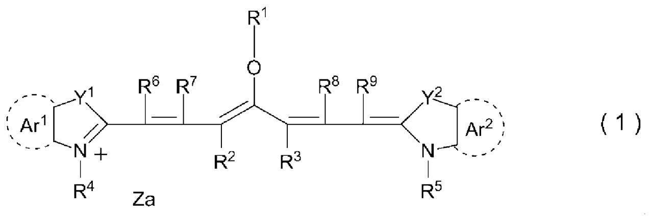

特許文献2:米国特許出願公開第2009/0269699号明細書
本開示の他の実施形態が解決しようとする課題は、上記機上現像型平版印刷版原版を用いた平版印刷版の作製方法、又は、平版印刷方法を提供することである。
<1> 波長760nm~900nmの範囲において、極大吸収波長を2つ以上有し、エネルギー密度110mJ/cm2にて波長830nmの赤外線による露光を行った場合の、上記露光を行った部分における上記露光前と上記露光後25℃70%RHの条件にて24時間保管後との明度変化ΔLが、3.0以上である機上現像型平版印刷版原版。
<2> 赤外線吸収剤A、及び、赤外線吸収剤Bを含み、上記赤外線吸収剤Aの最大吸収波長と上記赤外線吸収剤Bの最大吸収波長とが異なり、エネルギー密度110mJ/cm2にて波長830nmの赤外線による露光を行った場合の、上記露光を行った部分における上記露光前と上記露光後25℃70%RHの条件にて24時間保管後との明度変化ΔLが、3.0以上である機上現像型平版印刷版原版。
<3> 支持体上に画像記録層を有し、上記画像記録層が、上記赤外線吸収剤A、及び、上記赤外線吸収剤Bを含む<2>に記載の機上現像型平版印刷版原版。
<4> 支持体と、画像記録層と、最外層と、をこの順で有し、上記画像記録層が、赤外線吸収剤Aを含み、上記最外層が、赤外線吸収剤Bを含む<2>に記載の機上現像型平版印刷版原版。
<5> 上記赤外線吸収剤Aの最大吸収波長が、830nm超である<2>~<4>のいずれか1つに記載の機上現像型平版印刷版原版。
<6> 上記赤外線吸収剤Bの最大吸収波長が、830nm以下である<2>~<5>のいずれか1つに記載の機上現像型平版印刷版原版。
<7> 上記赤外線吸収剤Aの最大吸収波長と上記赤外線吸収剤Bの最大吸収波長の差が、5nm~50nmである<2>~<6>のいずれか1つに記載の機上現像型平版印刷版原版。
<8> 上記赤外線吸収剤Bが、赤外線露光に起因して分解する分解型赤外線吸収剤である<2>~<7>のいずれか1つに記載の機上現像型平版印刷版原版。
<9> 上記分解型赤外線吸収剤が、下記式1-1で表される化合物である<8>に記載の機上現像型平版印刷版原版。
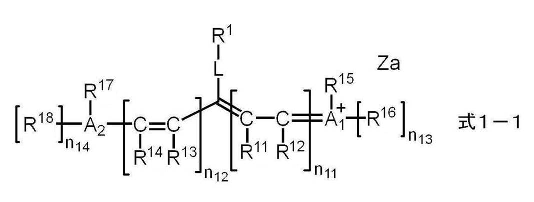


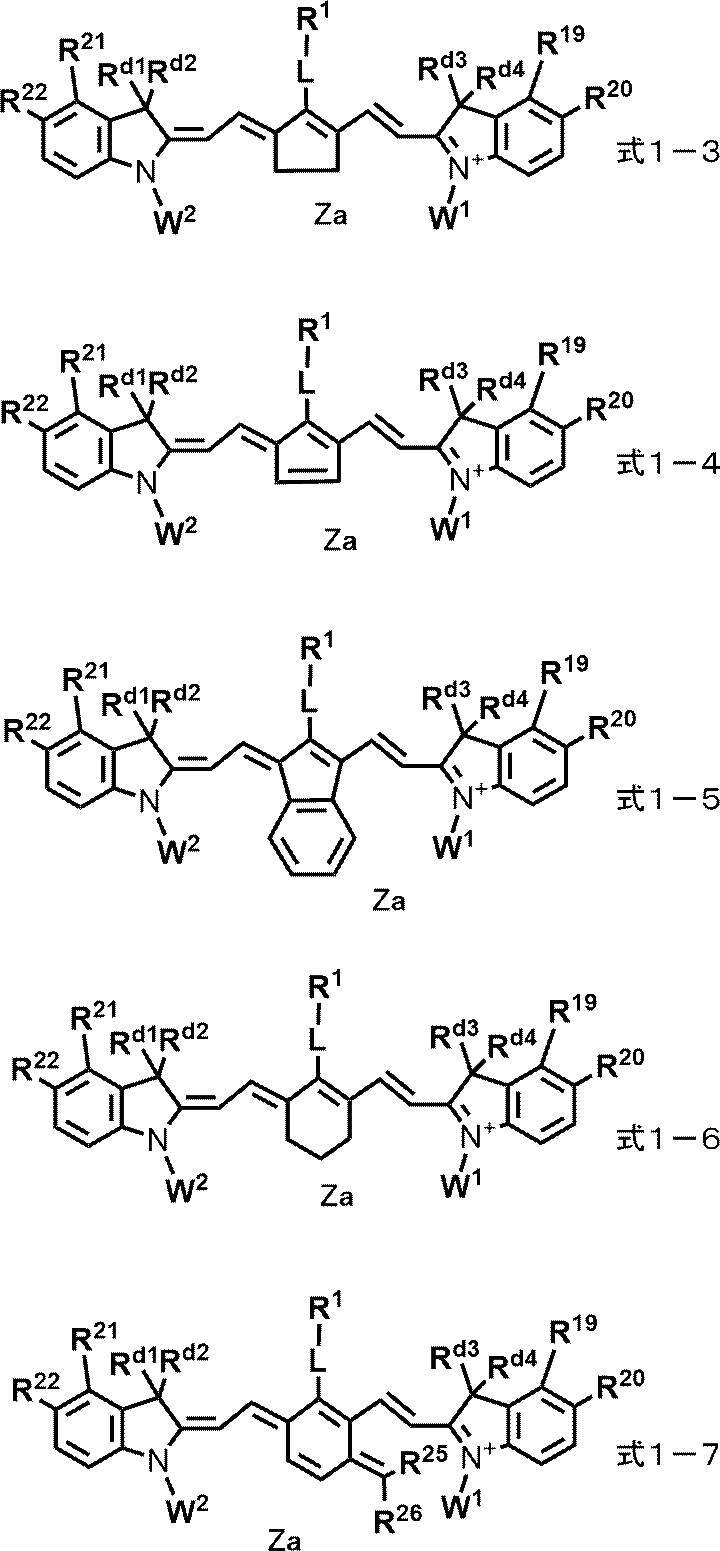
<13> 上記画像記録層が、電子供与型重合開始剤を含む<3>又は<4>に記載の機上現像型平版印刷版原版。
<14> 上記赤外線吸収剤AのHOMO-上記電子供与型重合開始剤のHOMOの値が、0.60eV以下である<13>に記載の機上現像型平版印刷版原版。
<15> 上記赤外線吸収剤AのHOMOが、-5.30eV以下である<2>~<14>のいずれか1つに記載の機上現像型平版印刷版原版。
<16> 上記赤外線吸収剤Aが、下記式1で表される化合物を含む<2>~<15>のいずれか1つに記載の機上現像型平版印刷版原版。
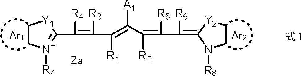
-X 式2
式2中、Xは、ハロゲン原子、-C(=O)-X2-R11、-C(=O)-NR12R13、-O-C(=O)-R14、-CN、-SO2NR15R16、又は、パーフルオロアルキル基を表し、X2は、単結合又は酸素原子を表し、R11及びR14はそれぞれ独立に、アルキル基又はアリール基を表し、R12、R13、R15及びR16はそれぞれ独立に、水素原子、アルキル基又はアリール基を表す。
なお、R17は、アルキル基又はアリール基を表す。
<18> 式1におけるAr1及びAr2の少なくとも一方に、臭素原子を有する<16>又は<17>に記載の機上現像型平版印刷版原版。
<19> 上記電子供与型重合開始剤のHOMOが、-5.90eVより大きい<13>又は<14>に記載の機上現像型平版印刷版原版。
<20> 上記画像記録層が、電子受容型重合開始剤を含む<3>又は<4>に記載の機上現像型平版印刷版原版。
<21> 上記電子受容型重合開始剤が、オニウム塩化合物である<20>に記載の機上現像型平版印刷版原版。
<22> 上記電子受容型重合開始剤が、下記式(II)で表される化合物を含む<20>又は<21>に記載の機上現像型平版印刷版原版。

<24> 上記酸発色剤が、下記式(Le-8)で表される化合物を含む<23>に記載の機上現像型平版印刷版原版。
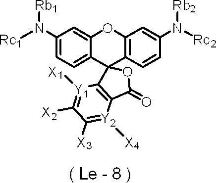
<26> 上記酸発色剤が、下記式(Le-10)で表される化合物を含む<23>に記載の機上現像型平版印刷版原版。
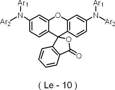
<28> 上記酸発色剤が、下記式(Le-11)で表される化合物を含む<23>に記載の機上現像型平版印刷版原版。

<30> 上記画像記録層が、重合性化合物を含む<3>、<4>及び<23>~<29>のいずれか1つに記載の機上現像型平版印刷版原版。
<31> 上記重合性化合物が、2官能以下の重合性化合物を含む<30>に記載の機上現像型平版印刷版原版。
<32> 上記重合性化合物が、7官能以上の重合性化合物を含む<30>又は<31>に記載の機上現像型平版印刷版原版。
<33> 上記支持体と、上記画像記録層と、最外層と、をこの順で有する<3>に記載の機上現像型平版印刷版原版。
<34> 上記最外層が、疎水性ポリマーを含む<4>、<29>又は<33>に記載の機上現像型平版印刷版原版。
<35> 上記疎水性ポリマーが、疎水性ポリマー粒子である<34>に記載の機上現像型平版印刷版原版。
<36> 上記支持体が、アルミニウム板と、上記アルミニウム板上に配置されたアルミニウムの陽極酸化皮膜とを有し、上記陽極酸化皮膜が、上記アルミニウム板よりも上記画像記録層側に位置し、上記陽極酸化皮膜が、上記画像記録層側の表面から深さ方向にのびるマイクロポアを有し、上記マイクロポアの上記陽極酸化皮膜表面における平均径が、10nmを超え100nm以下である<3>又は<4>に記載の機上現像型平版印刷版原版。
<37> 上記マイクロポアが、上記陽極酸化皮膜表面から深さ10nm~1,000nmの位置までのびる大径孔部と、上記大径孔部の底部と連通し、連通位置から深さ20nm~2,000nmの位置までのびる小径孔部とから構成され、上記大径孔部の上記陽極酸化皮膜表面における平均径が、15nm~100nmであり、上記小径孔部の上記連通位置における平均径が、13nm以下である<36>に記載の機上現像型平版印刷版原版。
<38> <1>~<37>のいずれか1つに記載の機上現像型平版印刷版原版を、画像様に露光する工程と、印刷機上で印刷インク及び湿し水よりなる群から選ばれた少なくとも一方を供給して非画像部の画像記録層を除去する工程と、を含む平版印刷版の作製方法。
<39> <1>~<37>のいずれか1つに記載の機上現像型平版印刷版原版を、画像様に露光する工程と、印刷機上で印刷インク及び湿し水よりなる群から選ばれた少なくとも一方を供給して非画像部の画像記録層を除去し平版印刷版を作製する工程と、得られた平版印刷版により印刷する工程と、を含む平版印刷方法。
また、本開示の他の実施形態によれば、上記機上現像型平版印刷版原版を用いた平版印刷版の作製方法又は平版印刷版の印刷方法を提供することができる。
なお、本明細書において、数値範囲を示す「~」とはその前後に記載される数値を下限値及び上限値として含む意味で使用される。
また、本明細書における基(原子団)の表記において、置換及び無置換を記していない表記は、置換基を有さないものと共に置換基を有するものをも包含するものである。例えば「アルキル基」とは、置換基を有さないアルキル基(無置換アルキル基)のみならず、置換基を有するアルキル基(置換アルキル基)をも包含するものである。
本明細書において、「(メタ)アクリル」は、アクリル及びメタクリルの両方を包含する概念で用いられる語であり、「(メタ)アクリロイル」は、アクリロイル及びメタクリロイルの両方を包含する概念として用いられる語である。
また、本明細書中の「工程」の用語は、独立した工程だけではなく、他の工程と明確に区別できない場合であっても、その工程の所期の目的が達成されれば本用語に含まれる。 また、本開示において、「質量%」と「重量%」とは同義であり、「質量部」と「重量部」とは同義である。
特に限定しない限りにおいて、本開示において組成物中の各成分、又は、ポリマー中の各構成単位は、1種単独で含まれていてもよいし、2種以上を併用してもよいものとする。
更に、本開示において組成物中の各成分、又は、ポリマー中の各構成単位の量は、組成物中に各成分、又は、ポリマー中の各構成単位に該当する物質又は構成単位が複数存在する場合、特に断らない限り、組成物中に存在する該当する複数の物質、又は、ポリマー中に存在する該当する複数の各構成単位の合計量を意味する。
更に、本開示において、2以上の好ましい態様の組み合わせは、より好ましい態様である。
また、本開示における重量平均分子量(Mw)及び数平均分子量(Mn)は、特に断りのない限り、TSKgel GMHxL、TSKgel G4000HxL、TSKgel G2000HxL(何れも東ソー(株)製の商品名)のカラムを使用したゲルパーミエーションクロマトグラフィ(GPC)分析装置により、溶媒THF(テトラヒドロフラン)、示差屈折計により検出し、標準物質としてポリスチレンを用いて換算した分子量である。
本開示において、「平版印刷版原版」の用語は、平版印刷版原版だけでなく、捨て版原版を包含する。また、「平版印刷版」の用語は、平版印刷版原版を、必要により、露光、現像などの操作を経て作製された平版印刷版だけでなく、捨て版を包含する。捨て版原版の場合には、必ずしも、露光、現像の操作は必要ない。なお、捨て版とは、例えばカラーの新聞印刷において一部の紙面を単色又は2色で印刷を行う場合に、使用しない版胴に取り付けるための平版印刷版原版である。
また、本開示において、化学構造式における「*」は、他の構造との結合位置を表す。
以下、本開示を詳細に説明する。
本開示に係る機上現像型平版印刷版原版(単に「平版印刷版原版」ともいう。)の第一の実施態様は、波長760nm~900nmの範囲において、極大吸収波長を2つ以上有し、エネルギー密度110mJ/cm2にて波長830nmの赤外線による露光を行った場合の、上記露光を行った部分における上記露光前と上記露光後25℃70%RHの条件にて24時間保管後との明度変化ΔLが、3.0以上である。
本開示に係る機上現像型平版印刷版原版の第二の実施態様は、赤外線吸収剤A、及び、赤外線吸収剤Bを含み、上記赤外線吸収剤Aの最大吸収波長と上記赤外線吸収剤Bの最大吸収波長とが異なり、エネルギー密度110mJ/cm2にて波長830nmの赤外線による露光を行った場合の、上記露光を行った部分における上記露光前と上記露光後25℃70%RHの条件にて24時間保管後との明度変化ΔLが、3.0以上である。
また、本開示に係る機上現像型平版印刷版原版は、ネガ型平版印刷版原版であることが好ましい。
本発明者らが鋭意検討した結果、経時後における露光部の視認性(単に「経時視認性」ともいう。)、及び、保存安定性に優れる平版印刷版原版を提供することができることを見出した。
上記効果が得られる詳細なメカニズムは不明であるが、以下のように推測される。
波長760nm~900nmの範囲において、極大吸収波長を2つ以上有するか、又は、最大吸収波長が互いに異なる赤外線吸収剤A及び赤外線吸収剤Bを含むことにより、互いの極大又は最大吸収波長における吸収が、暗重合を抑制するとともに、露光時に生じる発色の経時による劣化も抑制することにより、経時後における露光部の視認性、及び、保存安定性に優れると推定している。
平版印刷版において、版の印刷可能な枚数が多いことを、「耐刷性に優れる」という。紫外線硬化型インキ(UVインキ)を用いた場合の耐刷性を、以下、「UV耐刷性」ともいう。
本開示に係る機上現像型平版印刷版原版は、上記明度変化ΔLが、経時視認性、保存安定性、及び、UV耐刷性の観点から、5.0以上であることが好ましく、5.0~20.0であることが特に好ましい。
平版印刷版原版を、波長830nmの赤外線半導体レーザー搭載の富士フイルム グラフィックシステムズ(株)製Luxel PLATESETTER T-9800により、出力99.5%、外面ドラム回転数220rpm、解像度2,400dpi(dots per inch、1inch=25.4mm)の条件(エネルギー密度110mJ/cm2)で露光する。露光は25℃、50%RHの環境下で行う。
露光した平版印刷版原版を25℃70%RHの条件にて24保管し、保管前後の平版印刷版原版の明度変化を測定する。測定には、X-Rite社製分光測色計eXactを用いる。L*a*b*表色系のL*値(明度)を用い、露光後の露光部のL*値と露光前の露光部のL*値との差の絶対値を明度変化ΔLとする。
本開示に係る機上現像型平版印刷版原版の第二の実施態様は、経時視認性、保存安定性、及び、UV耐刷性の観点から、波長760nm~900nmの範囲において、極大吸収波長を2つ以上有することが好ましく、波長760nm~900nmの範囲において、極大吸収波長を3つ以上有することがより好ましく、波長760nm~900nmの範囲において、極大吸収波長を3つ以上10以下有することが更に好ましい。
本開示に係る機上現像型平版印刷版原版の第一の実施態様は、経時視認性、保存安定性、及び、UV耐刷性の観点から、赤外線吸収剤A、及び、赤外線吸収剤Bを含むことが好ましく、上記赤外線吸収剤Aの最大吸収波長と上記赤外線吸収剤Bの最大吸収波長とが異なることがより好ましい。
本開示に係る機上現像型平版印刷版原版は、赤外線吸収剤A、及び、赤外線吸収剤Bをいずれの層に含んでいてもよく、また、別々の層にそれぞれ含んでいてもよいが、経時視認性、保存安定性、及び、UV耐刷性の観点から、支持体上に画像記録層を有し、上記画像記録層が、上記赤外線吸収剤A、及び、上記赤外線吸収剤Bを含むか、又は、支持体と、画像記録層と、最外層と、をこの順で有し、上記画像記録層が、赤外線吸収剤Aを含み、上記最外層が、赤外線吸収剤Bを含むことが好ましい。
また、本開示に係る機上現像型平版印刷版原版は、UV耐刷性の観点からは、支持体上に画像記録層を有し、上記画像記録層が、上記赤外線吸収剤A、及び、上記赤外線吸収剤Bを含むことはより好ましく、保存安定性の観点からは、支持体と、画像記録層と、最外層と、をこの順で有し、上記画像記録層が、赤外線吸収剤Aを含み、上記最外層が、赤外線吸収剤Bを含むことがより好ましい。
更に、本開示に係る機上現像型平版印刷版原版は、経時視認性、保存安定性、及び、UV耐刷性の観点から、上記画像記録層が、赤外線吸収剤Cを更に含み、上記赤外線吸収剤Aの最大吸収波長と上記赤外線吸収剤Bの最大吸収波長と上記赤外線吸収剤Cの最大吸収波長とがいずれも異なることが好ましく、支持体と、画像記録層と、最外層と、をこの順で有し、上記画像記録層が、赤外線吸収剤A、及び、赤外線吸収剤Bを含み、上記最外層が、赤外線吸収剤Cを含むことが特に好ましい。
また、最外層は、経時視認性、保存安定性、及び、UV耐刷性の観点から、少なくとも1種の分解型赤外線吸収剤を含むことが好ましい。
更に、上記分解型赤外線吸収剤は、上記分解により発色する分解発色型赤外線吸収剤であることが好ましい。
なお、本開示において、赤外線吸収剤における発色とは、赤外線露光前よりも、赤外線露光後に可視光領域(400nm以上750nm未満の波長域)における吸収が増加することを示す。例えば、赤外線吸収剤における発色には、赤外線露光前よりも、赤外線露光後において、可視光領域よりも低波長領域の吸収が可視光領域に長波長化することも包含する。
また、上記赤外線吸収剤Bは、経時視認性、保存安定性、及び、UV耐刷性の観点から、赤外線露光に起因して分解する分解型赤外線吸収剤であることが好ましい。
更に、経時視認性、保存安定性、及び、UV耐刷性の観点から、上記赤外線吸収剤Aが、非分解型赤外線吸収剤又は分解型赤外線吸収剤であり、かつ上記赤外線吸収剤Bが、分解型赤外線吸収剤であることが好ましく、上記赤外線吸収剤Aが、非分解型赤外線吸収剤であり、かつ上記赤外線吸収剤Bが、分解型赤外線吸収剤であることがより好ましい。
また、上記最外層が赤外線吸収剤を含む場合、上記最外層に含まれる赤外線吸収剤は、分解型赤外線吸収剤であることが好ましい。
上記赤外線吸収剤Bの最大吸収波長は、経時視認性、保存安定性、及び、UV耐刷性の観点から、830nm以下であることが好ましく、760nm~830nmであることがより好ましく、760nm~820nmであることが更に好ましく、765nm~810nmであることが特に好ましい。
また、上記赤外線吸収剤Aの最大吸収波長と上記赤外線吸収剤Bの最大吸収波長の差は、経時視認性、保存安定性、及び、UV耐刷性の観点から、5nm以上であることが好ましく、5nm~50nmであることがより好ましく、10nm~50nmであることが更に好ましく、20nm~50nmであることが特に好ましい。
まず、計算対象となる化合物における遊離の対イオンは計算対象から除外する。例えば、カチオン性の一電子受容型重合開始剤、カチオン性の赤外線吸収剤では対アニオンを、アニオン性の一電子供与型重合開始剤では対カチオンをそれぞれ計算対象から除外する。ここでいう遊離とは、対象とする化合物とその対イオンが共有結合で連結されていないことを意味する。
量子化学計算ソフトウェアGaussian09を用い、構造最適化はDFT(B3LYP/6-31G(d))で行う。
MO(分子軌道)エネルギー計算は、上記構造最適化で得た構造でDFT(B3LYP/6-31+G(d,p)/CPCM(solvent=methanol))で行う。
上記MOエネルギー計算で得られたMOエネルギーEbare(単位:hartree)を以下の公式により、本開示においてHOMO及びLUMOの値として用いるEscaled(単位:eV)へ変換する。
Escaled=0.823168×27.2114×Ebare-1.07634
なお、27.2114は単にhartreeをeVに変換するための係数であり、0.823168と-1.07634とは調節係数であり、計算対象となる化合物のHOMOとLUMOとを計算が実測の値に合うように定める。
本開示に係る平版印刷版原版は、支持体上に形成された画像記録層を有することが好ましい。
本開示に係る機上現像型平版印刷版原版は、重合性化合物、重合開始剤、赤外線吸収剤(例えば、赤外線吸収剤A若しくは赤外線吸収剤Bのみ、又は、赤外線吸収剤A及び赤外線吸収剤Bを含む)を含むことが好ましい。
本開示に用いられる画像記録層は、ネガ型画像記録層であることが好ましく、水溶性又は水分散性のネガ型画像記録層であることがより好ましい。
本開示に係る平版印刷版原版は、機上現像性の観点から、画像記録層の未露光部が湿し水及び印刷インキの少なくともいずれかにより除去可能であることが好ましい。
本開示に係る機上現像型平版印刷版原版は、画像記録層に、赤外線吸収剤A、及び、赤外線吸収剤Bの少なくともいずれかを含むことが好ましい。
また、上記画像記録層は、赤外線吸収剤A、及び、赤外線吸収剤Bだけでなく、これら以外の、赤外線吸収剤C、赤外線吸収剤D等を更に含んでいてもよい。
なお、本明細書において、特に断りなく、単に「赤外線吸収剤」という場合は、赤外線吸収剤A、赤外線吸収剤B、赤外線吸収剤C、赤外線吸収剤D等の全てについて述べるものとする。
赤外線吸収剤として用いられる染料としては、市販の染料及び例えば、「染料便覧」(有機合成化学協会編集、昭和45年刊)等の文献に記載されている公知のものが利用できる。具体的には、アゾ染料、金属錯塩アゾ染料、ピラゾロンアゾ染料、ナフトキノン染料、アントラキノン染料、フタロシアニン染料、カルボニウム染料、キノンイミン染料、メチン染料、シアニン染料、スクアリリウム色素、ピリリウム塩、金属チオレート錯体等の染料が挙げられる。
また、特開平5-5005号公報の段落0008~0009、特開2001-222101号公報の段落0022~0025に記載の化合物も好ましく使用することができる。
顔料としては、特開2008-195018号公報の段落0072~0076に記載の化合物が好ましい。
上記赤外線吸収剤として、分解型赤外線吸収剤を用いることにより、上記赤外線吸収剤又はその分解物が重合を促進し、また、上記赤外線吸収剤の分解物と重合性化合物とが相互作用することにより、UV耐刷性に優れると推定している。
上記分解型赤外線吸収剤は、赤外線露光により、赤外線を吸収し、分解して、発色する機能を有する赤外線吸収剤であることが好ましい。
以降、分解型赤外線吸収剤が、赤外線露光により、赤外線を吸収し、分解して形成される発色した化合物を、「分解型赤外線吸収剤の発色体」ともいう。
また、分解型赤外線吸収剤は、赤外線露光により、赤外線を吸収し、吸収した赤外線を熱に変換する機能を有することが好ましい。
上記分解型赤外線吸収剤は、赤外線波長域(波長750nm~1mm)の少なくとも1部の光を吸収し、分解するものであればよいが、750nm~1,400nmの波長域に極大吸収波長を有する赤外線吸収剤であることが好ましく、760nm~900nmの波長域に極大吸収波長を有する赤外線吸収剤であることがより好ましい。
より具体的には、分解型赤外線吸収剤は、赤外線露光に起因して分解し、500nm~600nmの波長域に極大吸収波長を有する化合物を生成する化合物であることが好ましい。

-X 式2
式2中、Xは、ハロゲン原子、-C(=O)-X2-R11、-C(=O)-NR12R13、-O-C(=O)-R14、-CN、-SO2NR15R16、又は、パーフルオロアルキル基を表し、X2は、単結合又は酸素原子を表し、R11及びR14はそれぞれ独立に、アルキル基又はアリール基を表し、R12、R13、R15及びR16はそれぞれ独立に、水素原子、アルキル基又はアリール基を表す。
また、式1においては、Ar1及びAr2の少なくとも一方に、上記式2で表される基を有し、耐刷性、及び、視認性の観点から、Ar1及びAr2の両方に、上記式2で表される基を有することが好ましい。
R11及びR14はそれぞれ独立に、アルキル基又はアリール基を表し、炭素数1~12のアルキル基又は炭素数6~12のアリール基であることが好ましく、炭素数1~12のアルキル基であることがより好ましい。
R12、R13、R15及びR16はそれぞれ独立に、水素原子、アルキル基又はアリール基を表し、水素原子、炭素数1~12のアルキル基又は炭素数6~12のアリール基であることが好ましく、水素原子又は炭素数1~12のアルキル基であることがより好ましく、炭素数1~12のアルキル基であることが更に好ましい。
R17は、アルキル基又はアリール基を表し、炭素数1~12のアルキル基又は炭素数6~12のアリール基であることが好ましく、炭素数1~12のアルキル基であることがより好ましい。
また、A1は、UV版飛び抑制性、GLV適性及びUV耐刷性の観点からは、-Xであることが好ましく、ハロゲン原子であることがより好ましく、塩素原子、又は、臭素原子であることが更に好ましく、塩素原子であることが特に好ましい。
R9及びR10はそれぞれ独立に、アルキル基、アリール基、アルコキシカルボニル基又はアリールスルホニル基を表し、炭素数1~12のアルキル基又は炭素数6~12のアリール基であることが好ましく、炭素数1~12のアルキル基であることがより好ましい。
X1は酸素原子又は硫黄原子を表し、L1が炭化水素基又はヘテロアリール基である場合は、硫黄原子であることが好ましく、L1が熱若しくは赤外線露光によりX1との結合が開裂する基であることが好ましい。
L1は炭化水素基、ヘテロアリール基、又は、熱若しくは赤外線露光によりX1との結合が開裂する基を表し、耐刷性の観点からは、炭化水素基又はヘテロアリール基が好ましく、アリール基又はヘテロアリール基がより好ましく、ヘテロアリール基が更に好ましい。
また、L1は、視認性及び経時における退色抑制性の観点からは、熱若しくは赤外線露光によりX1との結合が開裂する基が好ましい。
熱若しくは赤外線露光によりX1との結合が開裂する基については、後述する。
R18及びR19はそれぞれ独立に、アリール基を表し、炭素数6~20のアリール基であることが好ましく、フェニル基であることがより好ましい。
R20は炭化水素基又はヘテロアリール基を表し、アリール基又はヘテロアリール基が好ましく、ヘテロアリール基がより好ましい。

具体的には、例えば、メチル基、エチル基、プロピル基、ブチル基、ペンチル基、ヘキシル基、ヘプチル基、オクチル基、ノニル基、デシル基、ウンデシル基、ドデシル基、トリデシル基、ヘキサデシル基、オクタデシル基、エイコシル基、イソプロピル基、イソブチル基、s-ブチル基、t-ブチル基、イソペンチル基、ネオペンチル基、1-メチルブチル基、イソヘキシル基、2-エチルヘキシル基、2-メチルヘキシル基、シクロヘキシル基、シクロペンチル基、及び、2-ノルボルニル基を挙げられる。
これらアルキル基の中でも、メチル基、エチル基、プロピル基又はブチル基が特に好ましい。
また、上記アリール基は、置換基を有していてもよい。置換基の例としては、アルキル基、アルコキシ基、アリーロキシ基、アミノ基、アルキルチオ基、アリールチオ基、ハロゲン原子、カルボキシ基、カルボキシレート基、スルホ基、スルホネート基、アルキルオキシカルボニル基、アリールオキシカルボニル基、及び、これらを組み合わせた基等が挙げられる。
上記アリール基としては具体的には、例えば、フェニル基、ナフチル基、p-トリル基、p-クロロフェニル基、p-フルオロフェニル基、p-メトキシフェニル基、p-ジメチルアミノフェニル基、p-メチルチオフェニル基、p-フェニルチオフェニル基等が挙げられる。
これらアリール基の中で、フェニル基、p-メトキシフェニル基、p-ジメチルアミノフェニル基、又は、ナフチル基が好ましい。
R1及びR2が連結して環を形成する場合、好ましい環員数は5又は6員環が好ましく、6員環がより好ましい。また、R1及びR2が連結して形成される環は、エチレン性不飽和結合を有していてもよい炭化水素環であることが好ましい。
R0は水素原子、アルキル基又はアリール基を表し、アルキル基であることが好ましい。
また、R7及びR8はそれぞれ独立に、直鎖アルキル基又は末端にスルホネート基を有するアルキル基であることが好ましく、メチル基、エチル基又は末端にスルホネート基を有するブチル基であることがより好ましい。
また、上記スルホネート基の対カチオンは、式1中の窒素原子上のカチオンであってもよいし、アルカリ金属カチオンやアルカリ土類金属カチオンであってもよい。
更に、式1で表される化合物の水溶性をさせる観点から、R7及びR8はそれぞれ独立に、アニオン構造を有するアルキル基であることが好ましく、カルボキシレート基又はスルホネート基を有するアルキル基であることがより好ましく、末端にスルホネート基を注するアルキル基であることが更に好ましい。
また、式1で表される化合物の極大吸収波長を長波長化し、また、視認性及び平版印刷版における耐刷性の観点から、R7及びR8はそれぞれ独立に、芳香環を有するアルキル基であることが好ましく、末端に芳香環を有するアルキル基であることがより好ましく、2-フェニルエチル基、2-ナフタレニルエチル基、又は、2-(9-アントラセニル)エチル基であることが特に好ましい。
更に、式1で表される化合物は、経時安定性、UV版飛び抑制性、GLV適性及びUV耐刷性の観点から、ハロゲン原子を2つ以上有することがより好ましく、ハロゲン原子を3つ以上有することが更に好ましく、ハロゲン原子を3つ以上6つ以下有することが特に好ましい。
また、上記ハロゲン原子としては、塩素原子、又は、臭素原子が好ましく挙げられる。
更にまた、式1で表される化合物は、経時安定性、UV版飛び抑制性、GLV適性及びUV耐刷性の観点から、Ar1及びAr2の少なくとも1方に、ハロゲン原子を有することが好ましく、Ar1及びAr2の少なくとも1方に、塩素原子、又は、臭素原子を有することがより好ましく、Ar1及びAr2の少なくとも1方に、臭素原子を有することが特に好ましい。
中でも、Zaは、耐刷性及び視認性の観点から、炭素原子を含む有機アニオンであることが好ましく、スルホネートイオン、カルボキシレートイオン、スルホンアミドアニオン又はスルホンイミドアニオンであることがより好ましく、スルホンアミドアニオン又はスルホンイミドアニオンであることが更に好ましく、スルホンイミドアニオンであることが特に好ましい。
R1~R8、R0、A1、Ar1、Ar2、Y1及びY2は、アニオン構造やカチオン構造を有していてもよく、R1~R8、R0、A1、Ar1、Ar2、Y1及びY2の全てが電荷的に中性の基であれば、Zaは一価の対アニオンであるが、例えば、R1~R8、R0、A1、Ar1、Ar2、Y1及びY2に2以上のアニオン構造を有する場合、Zaは対カチオンにもなり得る。
また、式1において、Za以外の部分が電荷的に中性であれば、Zaはなくともよい。
また、スルホンイミドアニオンとしては、ビスアリールスルホンイミドアニオンが好ましい。
スルホンアミドアニオン又はスルホンイミドアニオンの具体例を以下に示すが、本開示はこれらに限定されるものではない。下記具体例中、Phはフェニル基を、Meはメチル基を、Etはエチル基を、それぞれ表す。

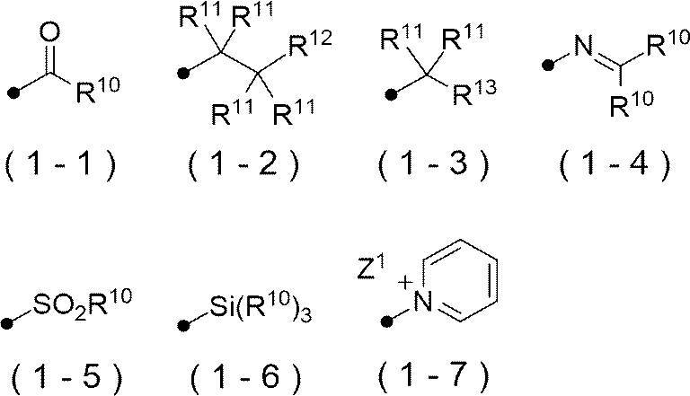
R10及びR13におけるアルケニル基の炭素数は、1~30であることが好ましく、1~15であることがより好ましく、1~10であることが更に好ましい。
R10~R18がアリール基である場合の好ましい態様は、R0におけるアリール基の好ましい態様と同様である。
また、式(1-1)におけるR10がアルキル基である場合、上記アルキル基は、α位にアリールチオ基又はアルキルオキシカルボニル基を有するアルキル基であることが好ましい。
式(1-1)におけるR10が-OR14である場合、R14は、アルキル基であることが好ましく、炭素数1~8のアルキル基であることがより好ましく、イソプロピル基又はt-ブチル基であることが更に好ましく、t-ブチル基であることが特に好ましい。
また、視認性の観点から、式(1-2)におけるR12は、-C(=O)OR14、-OC(=O)OR14又はハロゲン原子であることが好ましく、-C(=O)OR14又は-OC(=O)OR14であることがより好ましい。式(1-2)におけるR12が-C(=O)OR14又は-OC(=O)OR14である場合、R14は、アルキル基であることが好ましい。
また、R11におけるアルキル基は、炭素数1~10のアルキル基であることが好ましく、炭素数3~10のアルキル基であることがより好ましい。
更に、R11におけるアルキル基は、分岐を有するアルキル基、又は、シクロアルキル基であることが好ましく、第二級又は第三級アルキル基、又は、シクロアルキル基であることがより好ましく、イソプロピル基、シクロペンチル基、シクロヘキシル基、又は、t-ブチル基であることが更に好ましい。
また、視認性の観点から、式(1-3)におけるR13は、アリール基、アルコキシ基又はオニウム基であることが好ましく、p-ジメチルアミノフェニル基又はピリジニウム基であることがより好ましく、ピリジニウム基であることが更に好ましい。
R13におけるオニウム基としては、ピリジニウム基、アンモニウム基、スルホニウム基等が挙げられる。オニウム基は、置換基を有していてもよい。置換基としては、アルキル基、アルコキシ基、アリーロキシ基、アミノ基、アルキルチオ基、アリールチオ基、ハロゲン原子、カルボキシ基、スルホ基、アルキルオキシカルボニル基、アリールオキシカルボニル基、及び、これらを組み合わせた基等が挙げられるが、アルキル基、アリール基及びこれらを組み合わせた基であることが好ましい。
中でも、ピリジニウム基が好ましく、N-アルキル-3-ピリジニウム基、N-ベンジル-3-ピリジニウム基、N-(アルコキシポリアルキレンオキシアルキル)-3-ピリジニウム基、N-アルコキシカルボニルメチル-3-ピリジニウム基、N-アルキル-4-ピリジニウム基、N-ベンジル-4-ピリジニウム基、N-(アルコキシポリアルキレンオキシアルキル)-4-ピリジニウム基、N-アルコキシカルボニルメチル-4-ピリジニウム基、又は、N-アルキル-3,5-ジメチル-4-ピリジニウム基がより好ましく、N-アルキル-3-ピリジニウム基、又は、N-アルキル-4-ピリジニウム基が更に好ましく、N-メチル-3-ピリジニウム基、N-オクチル-3-ピリジニウム基、N-メチル-4-ピリジニウム基、又は、N-オクチル-4-ピリジニウム基が特に好ましく、N-オクチル-3-ピリジニウム基、又は、N-オクチル-4-ピリジニウム基が最も好ましい。
また、R13がピリジニウム基である場合、対アニオンとしては、スルホネートイオン、カルボキシレートイオン、テトラフルオロボレートイオン、ヘキサフルオロホスフェートイオン、p-トルエンスルホネートイオン、過塩素酸塩イオン等が挙げられ、p-トルエンスルホネートイオン、又は、ヘキサフルオロホスフェートイオンが好ましい。
視認性の観点から、式(1-5)におけるR10は、アルキル基又はアリール基であることが好ましく、アリール基であることがより好ましく、p-メチルフェニル基であることが更に好ましい。
視認性の観点から、式(1-6)におけるR10はそれぞれ独立に、アルキル基又はアリール基であることが好ましく、メチル基又はフェニル基であることがより好ましい。
視認性の観点から、式(1-7)におけるZ1は、電荷を中和する対イオンであればよく、化合物全体として、上記Zaに含まれてもよい。
Z1は、スルホネートイオン、カルボキシレートイオン、テトラフルオロボレートイオン、ヘキサフルオロホスフェートイオン、p-トルエンスルホネートイオン、又は、過塩素酸塩イオンであることが好ましく、p-トルエンスルホネートイオン、又は、ヘキサフルオロホスフェートイオンであることがより好ましい。
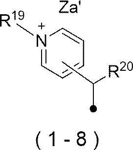
R19及びR20におけるアルキル基は、直鎖状であっても、分岐を有していても、環構造を有していてもよい。
また、上記アルキル基は、置換基を有していてもよく、置換基としては、アルコキシ基、及び、末端アルコキシポリアルキレンオキシ基が好ましく挙げられる。
R19は、炭素数1~12のアルキル基であることが好ましく、炭素数1~12の直鎖アルキル基であることがより好ましく、炭素数1~8の直鎖アルキル基であることが更に好ましく、メチル基又はn-オクチル基であることが特に好ましい。
R20は、炭素数1~8のアルキル基であることが好ましく、炭素数3~8の分岐アルキル基であることがより好ましく、イソプロピル基又はt-ブチル基であることが更に好ましく、イソプロピル基であることが特に好ましい。
Za’は、電荷を中和する対イオンであればよく、化合物全体として、上記Zaに含まれてもよい。
Za’は、スルホネートイオン、カルボキシレートイオン、テトラフルオロボレートイオン、ヘキサフルオロホスフェートイオン、p-トルエンスルホネートイオン、又は、過塩素酸塩イオンであることが好ましく、p-トルエンスルホネートイオン、又は、ヘキサフルオロホスフェートイオンであることがより好ましい。
分解型赤外線吸収剤としては、露光部の視認性を高める観点から、下記式1-1で表される化合物であることがより好ましい。

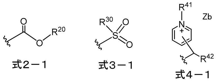
以下、式2-1で表される基、式3-1で表される基、及び式4-1で表される基についてそれぞれ説明する。
R20で表されるアルキル基としては、炭素数1~30のアルキル基が好ましく、炭素数1~15のアルキル基がより好ましく、炭素数1~10のアルキル基が更に好ましい。
上記アルキル基は、直鎖状であっても、分岐を有していても、環構造を有していてもよい。
R20で表されるアリール基としては、炭素数6~30のアリール基が好ましく、炭素数6~20のアリール基がより好ましく、炭素数6~12のアリール基が更に好ましい。
R20としては、視認性の観点から、アルキル基であることが好ましい。
更に、分解性、及び、視認性の観点から、R20で表されるアルキル基としては、炭素数1~8のアルキル基であることが好ましく、炭素数3~10の分岐状のアルキル基であることがより好ましく、炭素数3~6の分岐状のアルキル基であることが更に好ましく、イソプロピル基、又はtert-ブチル基が特に好ましく、tert-ブチル基が最も好ましい。
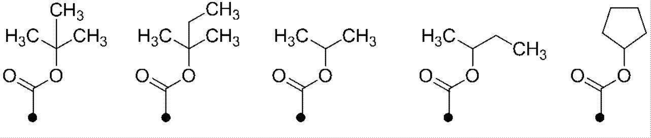
R30で表されるアルキル基及びアリール基としては、式2-1中のR20で表されるアルキル基及びアリール基と同様であり、好ましい態様も同様である。
また、分解性、及び、視認性の観点から、R30で表されるアルキル基としては、炭素数1~8のアルキル基であることが好ましく、炭素数3~10の分岐状のアルキル基であることがより好ましく、炭素数3~6の分岐状のアルキル基であることが更に好ましく、イソプロピル基、又はtert-ブチル基が特に好ましく、tert-ブチル基が最も好ましい。
更に、分解性、及び、視認性の観点から、R30で表されるアルキル基は、置換アルキル基であることが好ましく、フルオロ置換アルキル基であることがより好ましく、パーフルオロアルキル基であることが更に好ましく、トリフルオロメチル基であることが特に好ましい。
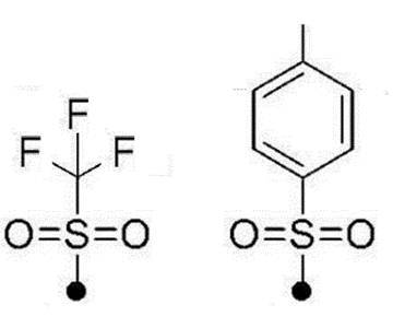
R41又はR42で表されるアルキル基及びアリール基としては、式2-1中のR20で表されるアルキル基及びアリール基と同様であり、好ましい態様も同様である。
R41としては、分解性、及び、視認性の観点から、アルキル基であることが好ましい。
R42としては、分解性、及び、視認性の観点から、アルキル基であることが好ましい。
分解性、及び、視認性の観点から、R42で表されるアルキル基としては、第二級アルキル基又は第三級アルキル基であることが好ましく、第三級アルキル基であることが好ましい。
また、分解性、及び、視認性の観点から、R42で表されるアルキル基としては、炭素数1~8のアルキル基であることが好ましく、炭素数3~10の分岐状のアルキル基であることがより好ましく、炭素数3~6の分岐状のアルキル基であることが更に好ましく、イソプロピル基、又は、tert-ブチル基が特に好ましく、tert-ブチル基が最も好ましい。
Zbは、スルホネートイオン、カルボキシレートイオン、テトラフルオロボレートイオン、ヘキサフルオロホスフェートイオン、p-トルエンスルホネートイオン、又は過塩素酸塩イオンが好ましく、テトラフルオロボレートイオンがより好ましい。

また、-NR10-におけるR10は、アルキル基が好ましい。R10で表されるアルキル基としては、炭素数1~10のアルキル基が好ましい。また、R10で表されるアルキル基は、直鎖状であっても、分岐を有していても、環構造を有していてもよい。
アルキル基の中では、メチル基又はシクロヘキシル基が好ましい。
-NR10-におけるR10がアリール基の場合、炭素数6~30のアリール基が好ましく、炭素数6~20のアリール基がより好ましく、炭素数6~12のアリール基が更に好ましい。また、これらアリール基は、置換基を有していてもよい。
Ra~Reで表される炭化水素基は、炭素数1~30の炭化水素基が好ましく、炭素数1~15の炭化水素基がより好ましく、炭素数1~10の炭化水素基が更に好ましい。
上記炭化水素基は、直鎖状であっても、分岐を有していても、環構造を有していてもよい。
上記炭化水素基としては、アルキル基が特に好ましい。
上記アルキル基は、直鎖状であっても、分岐を有していても、環構造を有していてもよい。
具体的には、例えば、メチル基、エチル基、プロピル基、ブチル基、ペンチル基、ヘキシル基、ヘプチル基、オクチル基、ノニル基、デシル基、ウンデシル基、ドデシル基、トリデシル基、ヘキサデシル基、オクタデシル基、エイコシル基、イソプロピル基、イソブチル基、s-ブチル基、tert-ブチル基、イソペンチル基、ネオペンチル基、1-メチルブチル基、イソヘキシル基、2-エチルヘキシル基、2-メチルヘキシル基、シクロヘキシル基、シクロペンチル基、及び、2-ノルボルニル基が挙げられる。
アルキル基の中で、メチル基、エチル基、プロピル基又はブチル基が好ましい。
置換基の例としては、アルコキシ基、アリーロキシ基、アミノ基、アルキルチオ基、アリールチオ基、ハロゲン原子、カルボキシ基、カルボキシレート基、スルホ基、スルホネート基、アルキルオキシカルボニル基、アリールオキシカルボニル基、及びこれらを組み合わせた基等が挙げられる。
中でも、Lが結合する炭素原子と結合する炭素原子に結合するR11及びR13は、アルキル基が好ましく、両者が連結して環を形成することがより好ましい。上記形成される環としては、単環であってもよく、多環であってもよい。形成される環として、具体的には、シクロペンテン環、シクロペンタジエン環、シクロヘキセン環、シクロヘキサジエン環等の単環、及び、インデン環、インドール環等の多環が挙げられる。
また、A1 +が結合する炭素原子に結合するR12はR15又はR16(好ましくはR16)と連結して環を形成することが好ましく、A2が結合する炭素原子に結合するR14はR17又はR18(好ましくはR18)と連結して環を形成することが好ましい。
また、R16は、A1 +が結合する炭素原子に結合するR12と連結して環を形成することが好ましい。形成される環としては、インドリウム環、ピリリウム環、チオピリリウム環、ベンゾオキサゾリン環、又はベンゾイミダゾリン環が好ましく、露光部の視認性を高める観点から、インドリウム環がより好ましい。これらの環は更に置換基を有していてもよい。
式1-1において、n14は1であり、R18は、-Ra(即ち炭化水素基)であることが好ましい。
また、R18は、A2が結合する炭素原子に結合するR14と連結して環を形成することが好ましい。形成される環としては、インドール環、ピラン環、チオピラン環、ベンゾオキサゾール環、又はベンゾイミダゾール環が好ましく、露光部の視認性を高める観点から、インドール環がより好ましい。これらの環は更に置換基を有していてもよい。
式1-1におけるR16及びR18は同一の基であることが好ましく、それぞれが環を形成する場合、A1 +及びA2を除き、同一の構造の環を形成することが好ましい。
R15又はR17で表される置換アルキル基としては、下記式(a1)~式(a4)のいずれかで表される基が挙げられる。
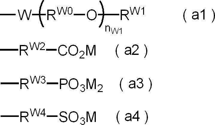
nW1は1~10が好ましく、1~5がより好ましく、1~3が特に好ましい。
RW1で表されるアルキル基の具体例としては、メチル基、エチル基、n-プロピル基、イソプロピル基、n-ブチル基、イソブチル基、tert-ブチル基、n-ペンチル基、イソペンチル基、ネオペンチル基、n-ヘキシル基、n-オクチル基、n-ドデシル基等が挙げられ、メチル基、エチル基、n-プロピル基、イソプロピル基、又はn-ブチル基、tert-ブチル基が好ましく、メチル基、又はエチル基が更に好ましく、メチル基が特に好ましい。
RW5で表されるアルキル基は、RW1で表されるアルキル基と同様であり、好ましい態様もRW1で表されるアルキル基の好ましい態様と同様である。
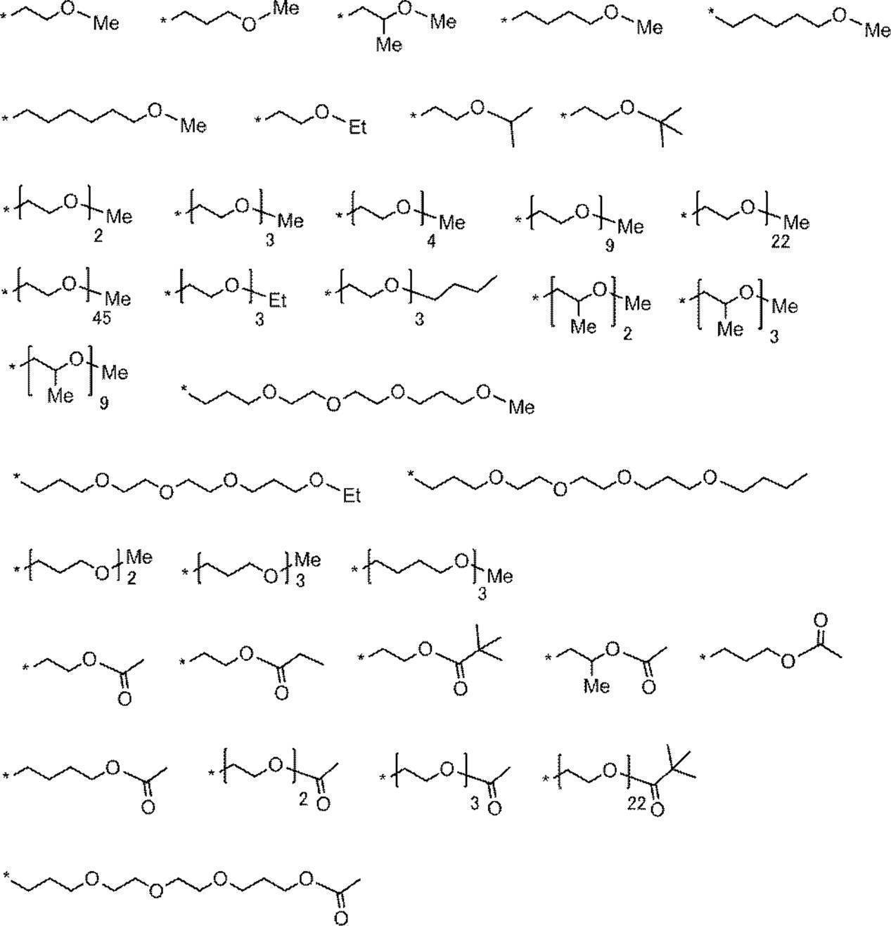
式(a3)において、2つ存在するMは同じでも異なってもよい。
式(a2)におけるCO2M、式(a2)におけるPO3M2、及び式(a4)におけるSO3Mは、いずれもMが解離したアニオン構造を有していてもよい。アニオン構造の対カチオンは、A1 +であってもよいし、式1-1中のR1-Lに含まれうるカチオンであってもよい。
式1-1におけるA1及びA2は同一の原子であることが好ましい。
R11~R18及びR1-Lの全てが電荷的に中性の基であれば、Zaは一価の対アニオンとなる。但し、R11~R18及びR1-Lは、アニオン構造又はカチオン構造を有していてもよく、例えば、R11~R18及びR1-Lに2以上のアニオン構造を有する場合、Zaは対カチオンにもなり得る。
なお、式1-1で表されるシアニン色素が、Zaを除き、化合物の全体において電荷的に中性な構造であれば、Zaは必要ない。
Zaが対アニオンである場合、スルホネートイオン、カルボキシレートイオン、テトラフルオロボレートイオン、ヘキサフルオロホスフェートイオン、p-トルエンスルホネートイオン、過塩素酸塩イオン等が挙げられ、テトラフルオロボレートイオンが好ましい。
Zaが対カチオンである場合、アルカリ金属イオン、アルカリ土類金属イオン、アンモニウムイオン、ピリジニウムイオン、スルホニウムイオン等が挙げられ、ナトリウムイオン、カリウムイオン、アンモニウムイオン、ピリジニウムイオン、又はスルホニウムイオンが好ましく、ナトリウムイオン、カリウムイオン、又はアンモニウムイオンがより好ましい。
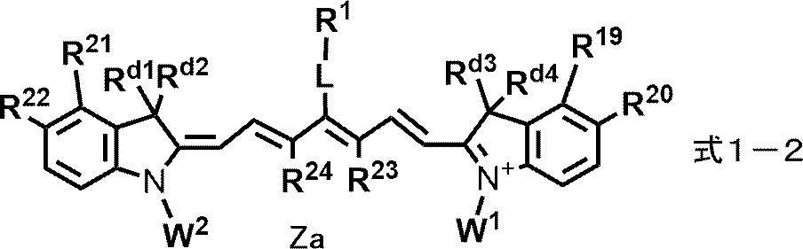
より具体的には、R19及びR21は、水素原子、又は-Raであることが好ましい。
また、R20及びR22は、水素原子、-Ra、-ORb、又は-CNであることが好ましい。
R19~R22で表される-Raとしては、アルキル基、又はアルケニル基が好ましい。
R19~R22のすべてが-Raである場合、R19とR20及びR21とR22が連結して単環又は多環を形成することが好ましい。
R19とR20又はR21とR22が連結して形成される環としては、ベンゼン環、ナフタレン環等が挙げられる。
R23とR24が連結して形成される環としては、単環であってもよく、多環であってもよい。形成される環として、具体的には、シクロペンテン環、シクロペンタジエン環、シクロヘキセン環、シクロヘキサジエン環等の単環、及び、インデン環等の多環が挙げられる。
無置換アルキル基としては、炭素数1~4の無置換アルキル基が挙げられ、中でも、メチル基が好ましい。
W1及びW2で表される置換アルキル基としては、式1-1における式(a1)~式(a4)のいずれかで表される基が挙げられ、好ましい態様も同様である。
また、W1及びW2はそれぞれ独立に、機上現像性の観点から、置換基を有するアルキル基であり、かつ、上記置換基として、-OCH2CH2-、スルホ基、スルホ基の塩、カルボキシ基、又は、カルボキシ基の塩を少なくとも有する基であることが好ましい。
R19~R22、R23~R24、Rd1~Rd4、W1、W2、及び、R1-Lの全てが電荷的に中性の基であれば、Zaは一価の対アニオンとなる。但し、R19~R22、R23~R24、Rd1~Rd4、W1、W2、及び、R1-Lは、アニオン構造又はカチオン構造を有していてもよく、例えば、R19~R22、R23~R24、Rd1~Rd4、W1、W2、及び、R1-Lに2以上のアニオン構造を有する場合、Zaは対カチオンにもなり得る。
なお、式1-2で表される化合物が、Zaを除き、化合物の全体において電荷的に中性な構造であれば、Zaは必要ない。
Zaが対アニオンである場合の例は、式1-1におけるZaと同様であり、好ましい態様も同様である。また、Zaが対カチオンである場合の例も、式1-1におけるZaと同様であり、好ましい態様も同様である。
特に、分解性、及び、視認性の観点から、式1-3、式1-5、及び式1-6のいずれかで表される化合物であることが好ましい。

式1-7におけるR25及びR26はそれぞれ独立に、水素原子又はアルキル基であることが好ましく、アルキル基であることがより好ましく、メチル基であることが特に好ましい。
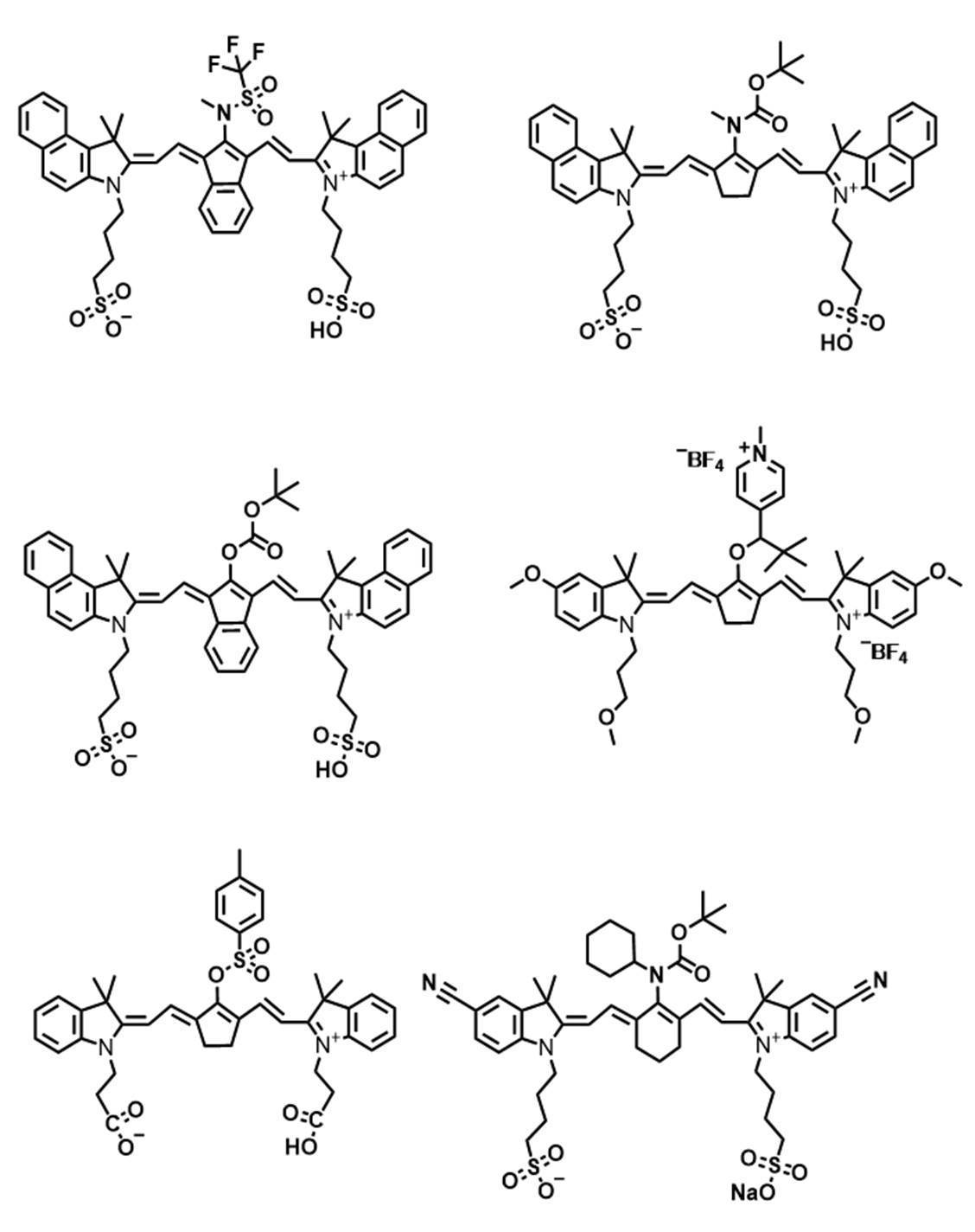
また、分解型赤外線吸収剤であるシアニン色素としては、国際公開第2019/219560号に記載の赤外線吸収性化合物を好適に用いることができる。
上記画像記録層中の赤外線吸収剤の総含有量は、画像記録層の全質量に対し、0.1質量%~10.0質量%が好ましく、0.5質量%~5.0質量%がより好ましい。
上記画像記録層が赤外線吸収剤A及び赤外線吸収剤Bを含む場合、上記画像記録層中の赤外線吸収剤A及び赤外線吸収剤Bの含有量はそれぞれ独立に、画像記録層の全質量に対し、0.1質量%~8.0質量%が好ましく、0.5質量%~4.5質量%がより好ましい。
また、上記画像記録層が赤外線吸収剤A及び赤外線吸収剤Bを含む場合、上記画像記録層中の赤外線吸収剤Aの含有量は、経時視認性、保存安定性、及び、UV耐刷性の観点から、赤外線吸収剤Bの含有量以上であることが好ましく、赤外線吸収剤Bの含有量よりも多いことがより好ましく、赤外線吸収剤Bの含有量よりも1.2質量倍~2.5質量倍多いことが特に好ましい。
更に、上記最外層が赤外線吸収剤を含む場合、上記画像記録層中の赤外線吸収剤の総含有量は、経時視認性、保存安定性、及び、UV耐刷性の観点から、上記最外層中の赤外線吸収剤の総含有量以上であることが好ましく、上記最外層中の赤外線吸収剤の総含有量よりも多いことがより好ましい。
本開示における画像記録層は、重合性化合物を含むことが好ましい。
本開示において、重合性化合物とは、重合性基を有する化合物をいう。
重合性基としては、特に限定されず公知の重合性基であればよいが、エチレン性不飽和基であることが好ましい。また、重合性基としては、ラジカル重合性基であってもカチオン重合性基であってもよいが、ラジカル重合性基であることが好ましい。
ラジカル重合性基としては、(メタ)アクリロイル基、アリル基、ビニルフェニル基、ビニル基等が挙げられ、反応性の観点から(メタ)アクリロイル基が好ましい。
重合性化合物の分子量(分子量分布を有する場合には、重量平均分子量)は、50以上2,500未満であることが好ましい。
エチレン性不飽和化合物としては、末端エチレン性不飽和結合を少なくとも1個有する化合物であることが好ましく、末端エチレン性不飽和結合を2個以上有する化合物であることがより好ましい。重合性化合物は、例えばモノマー、プレポリマー、すなわち2量体、3量体若しくはオリゴマー、又は、それらの混合物などの化学的形態をもつ。
中でも、上記重合性化合物としては、UV耐刷性の観点から、3官能以上の重合性化合物を含むことが好ましく、7官能以上の重合性化合物を含むことがより好ましく、10官能以上の重合性化合物を含むことが更に好ましい。また、上記重合性化合物は、得られる平版印刷版におけるUV耐刷性の観点から、3官能以上(好ましくは7官能以上、より好ましくは10官能以上)のエチレン性不飽和化合物を含むことが好ましく、3官能以上(好ましくは7官能以上、より好ましくは10官能以上)の(メタ)アクリレート化合物を含むことが更に好ましい。
2官能以下の重合性化合物(好ましくは2官能重合性化合物)の含有量は、耐刷性、機上現像性、及び、汚れ抑制性の観点から、上記画像記録層における重合性化合物の全質量に対し、5質量%~100質量%であることが好ましく、10質量%~100質量%であることがより好ましく、15質量%~100質量%であることが特に好ましい。
画像記録層に含まれる重合性化合物としては、オリゴマーである重合性化合物(以下、単に「オリゴマー」ともいう。)を含有することが好ましい。
本開示においてオリゴマーとは、分子量(分子量分布を有する場合には、重量平均分子量)が600以上10,000以下であり、かつ、重合性基を少なくとも1つ含む重合性化合物を表す。
耐薬品性、UV耐刷性に優れる観点から、オリゴマーの分子量としては、1,000以上5,000以下であることが好ましい。
また、オリゴマーにおける重合性基の上限値は、特に制限はないが、重合性基の数は20以下であることが好ましい。
なお、オリゴマーを製造する過程で生じる可能性のある、ポリマー成分を含有していてもよい。
本開示においてエポキシ残基とは、エポキシ基により形成される構造を指し、例えば酸基(カルボン酸基等)とエポキシ基との反応により得られる構造と同様の構造を意味する。

L1~L4としては、それぞれ独立に、炭素数2~20のアルキレン基であることが好ましく、炭素数2~10のアルキレン基であることがより好ましく、炭素数4~8のアルキレン基であることが更に好ましい。また、上記アルキレン基は、分岐又は環構造を有していてもよいが、直鎖アルキレン基であることが好ましい。
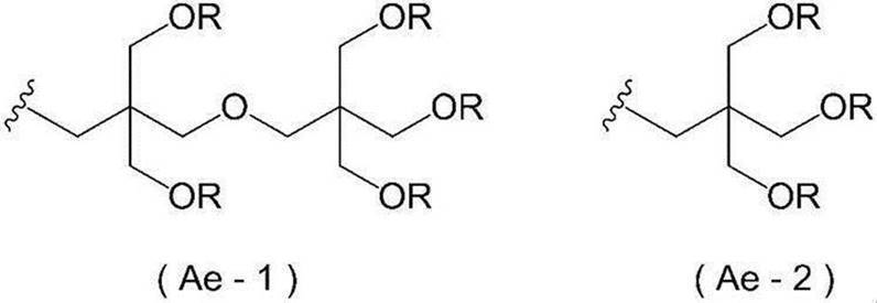
例えば、酸基を有するポリオール化合物と、ポリイソシアネート化合物を反応させて得られたポリウレタンオリゴマーに、エポキシ基及び重合性基を有する化合物を反応させることにより、ウレタン結合を有する化合物を得てもよい。
また、エポキシ残基を有する化合物における重合性基の数は、2~6であることが好ましく、2~3であることがより好ましい。
上記エポキシ残基を有する化合物としては、例えば、エポキシ基を有する化合物にアクリル酸を反応することにより得ることができる。
オリゴマーとしては、市販品を用いてもよく、UA510H、UA-306H、UA-306I、UA-306T(いずれも共栄社化学(株)製)、UV-1700B、UV-6300B、UV7620EA(いずれも日本合成化学工業(株)製)、U-15HA(新中村化学工業(株)製)、EBECRYL450、EBECRYL657、EBECRYL885、EBECRYL800、EBECRYL3416、EBECRYL860(いずれもダイセルオルネクス(株)製)等が挙げられるが、これに限定されるものではない。
重合性化合物は、上記オリゴマー以外の重合性化合物を更に含んでいてもよい。
オリゴマー以外の重合性化合物としては、耐薬品性の観点から、低分子重合性化合物であることが好ましい。低分子重合性化合物としては、単量体、2量体、3量体又は、それらの混合物などの化学的形態であってもよい。
また、低分子重合性化合物としては、耐薬品性の観点から、エチレン性不飽和基を3つ以上有する重合性化合物、及びイソシアヌル環構造を有する重合性化合物からなる群より選ばれる少なくとも一方の重合性化合物であることが好ましい。
低分子重合性化合物の分子量としては、耐薬品性、UV耐刷性及び機上現像カスの抑制性に優れる観点から、100以上600未満であることが好ましく、300以上600未満であることがより好ましく、400以上600未満であることが更に好ましい。
中でも、画像記録層は、UV耐刷性の観点から、2種以上の重合性化合物を含むことが好ましい。
重合性化合物の含有量(重合性化合物を2種以上含む場合は、重合性化合物の総含有量)は、画像記録層の全質量に対して、5質量%~75質量%であることが好ましく、10質量%~70質量%であることがより好ましく、15質量%~60質量%であることが更に好ましい。
本開示に係る平版印刷版原版における画像記録層は、重合開始剤を含むことが好ましい。
また、重合開始剤としては、感度、耐刷性、機上現像性、及び、着肉性の観点から、電子受容型重合開始剤を含むことが好ましく、電子受容型重合開始剤、及び、電子供与型重合開始剤を含むことがより好ましい。
上記画像記録層は、重合開始剤として、電子受容型重合開始剤を含むことが好ましい。
電子受容型重合開始剤は、赤外線露光により赤外線吸収剤の電子が励起した際に、分子間電子移動で一電子を受容することにより、ラジカル等の重合開始種を発生する化合物である。
本開示に用いられる電子受容型重合開始剤は、光、熱あるいはその両方のエネルギーによりラジカルやカチオン等の重合開始種を発生する化合物であって、公知の熱重合開始剤、結合解離エネルギーの小さな結合を有する化合物、光重合開始剤などを適宜選択して用いることができる。
電子受容型重合開始剤としては、ラジカル重合開始剤が好ましく、オニウム塩化合物がより好ましい。
また、電子受容型重合開始剤としては、赤外線感光性重合開始剤であることが好ましい。
電子受容型ラジカル重合開始剤としては、例えば、(a)有機ハロゲン化物、(b)カルボニル化合物、(c)アゾ化合物、(d)有機過酸化物、(e)メタロセン化合物、(f)アジド化合物、(g)ヘキサアリールビイミダゾール化合物、(i)ジスルホン化合物、(j)オキシムエステル化合物、(k)オニウム塩化合物が挙げられる。
(b)カルボニル化合物としては、例えば、特開2008-195018号公報の段落0024に記載の化合物が好ましい。
(c)アゾ化合物としては、例えば、特開平8-108621号公報に記載のアゾ化合物等を使用することができる。
(d)有機過酸化物としては、例えば、特開2008-195018号公報の段落0025に記載の化合物が好ましい。
(e)メタロセン化合物としては、例えば、特開2008-195018号公報の段落0026に記載の化合物が好ましい。
(f)アジド化合物としては、例えば、2,6-ビス(4-アジドベンジリデン)-4-メチルシクロヘキサノン等の化合物を挙げることができる。
(g)ヘキサアリールビイミダゾール化合物としては、例えば、特開2008-195018号公報の段落0027に記載の化合物が好ましい。
(i)ジスルホン化合物としては、例えば、特開昭61-166544号、特開2002-328465号の各公報に記載の化合物が挙げられる。
(j)オキシムエステル化合物としては、例えば、特開2008-195018号公報の段落0028~0030に記載の化合物が好ましい。
これら化合物の具体例を以下に示すが、本開示はこれに限定されるものではない。
スルホンアミドアニオンとしては、アリールスルホンアミドアニオンが好ましい。
また、スルホンイミドアニオンとしては、ビスアリールスルホンイミドアニオンが好ましい。
スルホンアミドアニオン又はスルホンイミドアニオンの具体例を以下に示すが、本開示はこれらに限定されるものではない。下記具体例中、Phはフェニル基を、Meはメチル基を、Etはエチル基を、それぞれ表す。

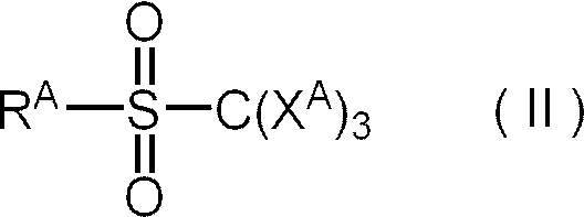
また、式(II)において、RAとしては、感度と保存安定性とのバランスに優れる観点から、アミド基で置換されているアリール基が好ましい。
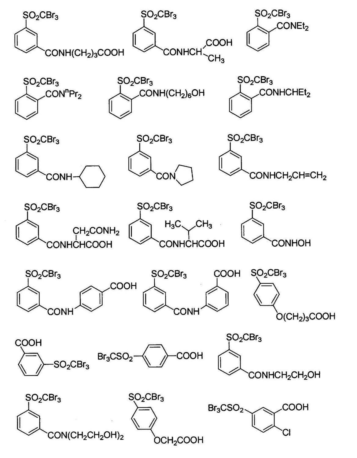
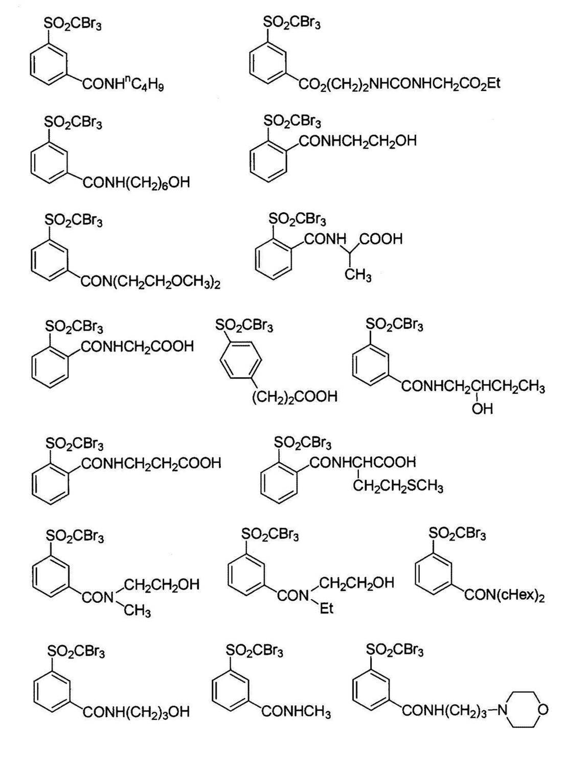


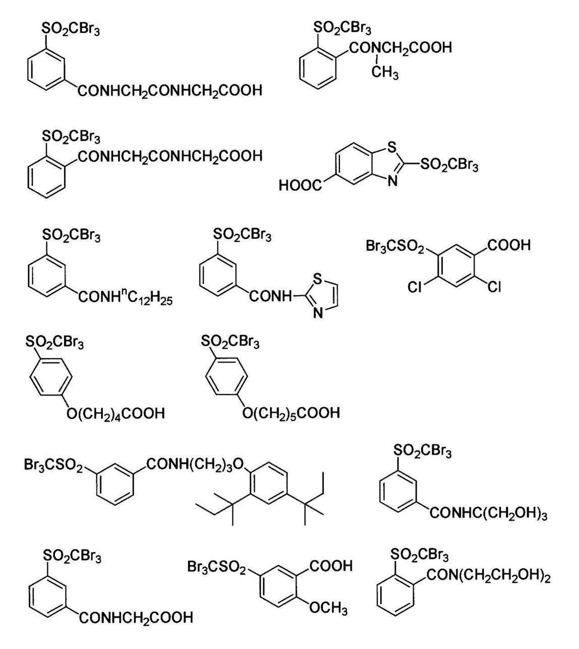
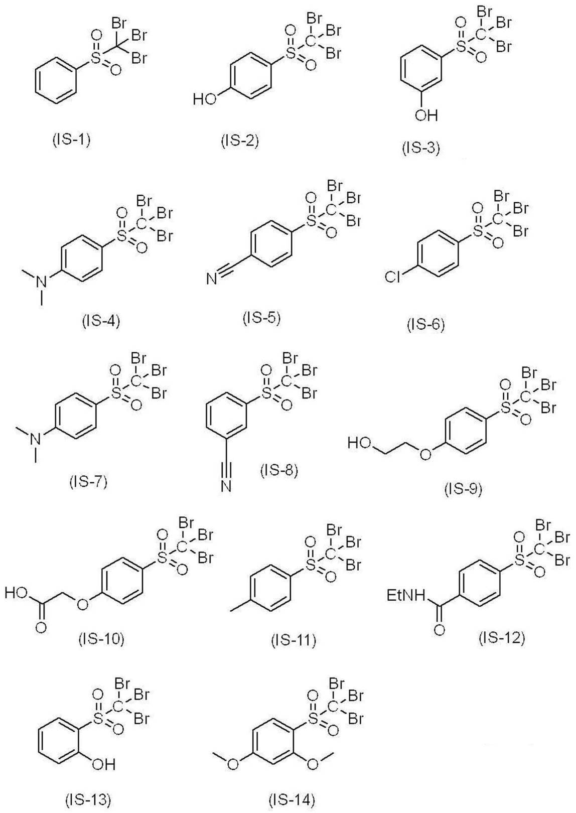
また、下限としては、-3.80eV以上であることが好ましく、-3.60eV以上であることがより好ましい。
電子受容型重合開始剤の含有量は、画像記録層の全質量に対して、0.1質量%~50質量%であることが好ましく、0.5質量%~30質量%であることがより好ましく、0.8質量%~20質量%であることが特に好ましい。
重合開始剤は、平版印刷版における耐薬品性、及び、UV耐刷性の向上に寄与する観点から、電子供与型重合開始剤を含むことが好ましく、電子供与型重合開始剤及び上記電子供与型重合開始剤の両方を含むことがより好ましい。
電子供与型重合開始剤としては、例えば、以下の5種類が挙げられる。
(i)アルキル又はアリールアート錯体:酸化的に炭素-ヘテロ結合が解裂し、活性ラジカルを生成すると考えられる。具体的には、ボレート塩化合物等が挙げられる。
(ii)アミノ酢酸化合物:酸化により窒素に隣接した炭素上のC-X結合が解裂し、活性ラジカルを生成するものと考えられる。Xとしては、水素原子、カルボキシ基、トリメチルシリル基又はベンジル基が好ましい。具体的には、N-フェニルグリシン類(フェニル基に置換基を有していてもよい。)、N-フェニルイミノジ酢酸(フェニル基に置換基を有していてもよい。)等が挙げられる。
(iii)含硫黄化合物:上述のアミノ酢酸化合物の窒素原子を硫黄原子に置き換えたものが、同様の作用により活性ラジカルを生成し得る。具体的には、フェニルチオ酢酸(フェニル基に置換基を有していてもよい。)等が挙げられる。
(iv)含錫化合物:上述のアミノ酢酸化合物の窒素原子を錫原子に置き換えたものが、同様の作用により活性ラジカルを生成し得る。
(v)スルフィン酸塩類:酸化により活性ラジカルを生成し得る。具体的は、アリールスルフィン酸ナトリウム等が挙げられる。
ボレート塩化合物が有する対カチオンとしては、特に制限はないが、アルカリ金属イオン、又は、テトラアルキルアンモニウムイオンであることが好ましく、ナトリウムイオン、カリウムイオン、又は、テトラブチルアンモニウムイオンであることがより好ましい。
また、上限としては、-5.00eV以下であることが好ましく、-5.40eV以下であることがより好ましい。
Z+で表される対カチオンとしては、Na+、K+、N+(Bu)4等が挙げられる。上記Buはn-ブチル基を表す。
また、Z+で表される対カチオンとしては、上記電子受容型重合開始剤におけるオニウムイオンも好適にあげられる。
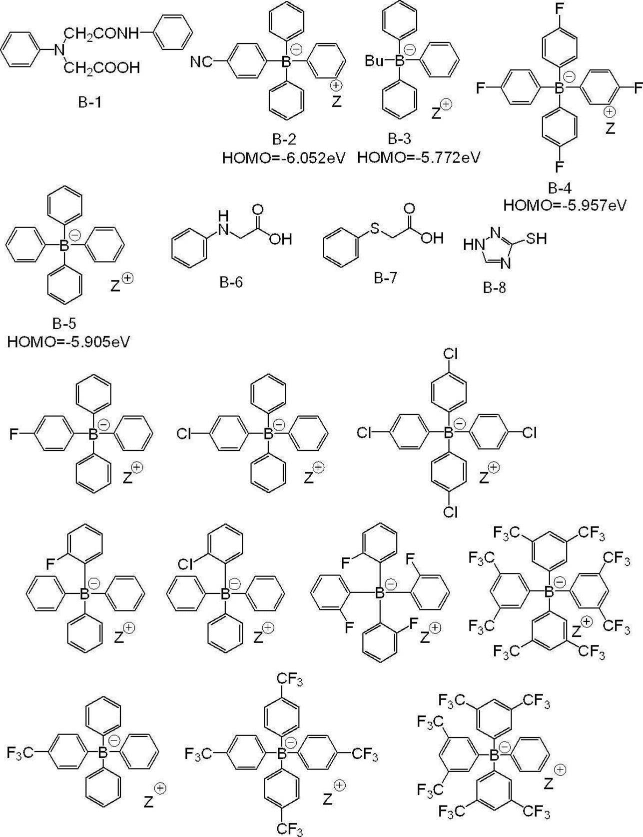
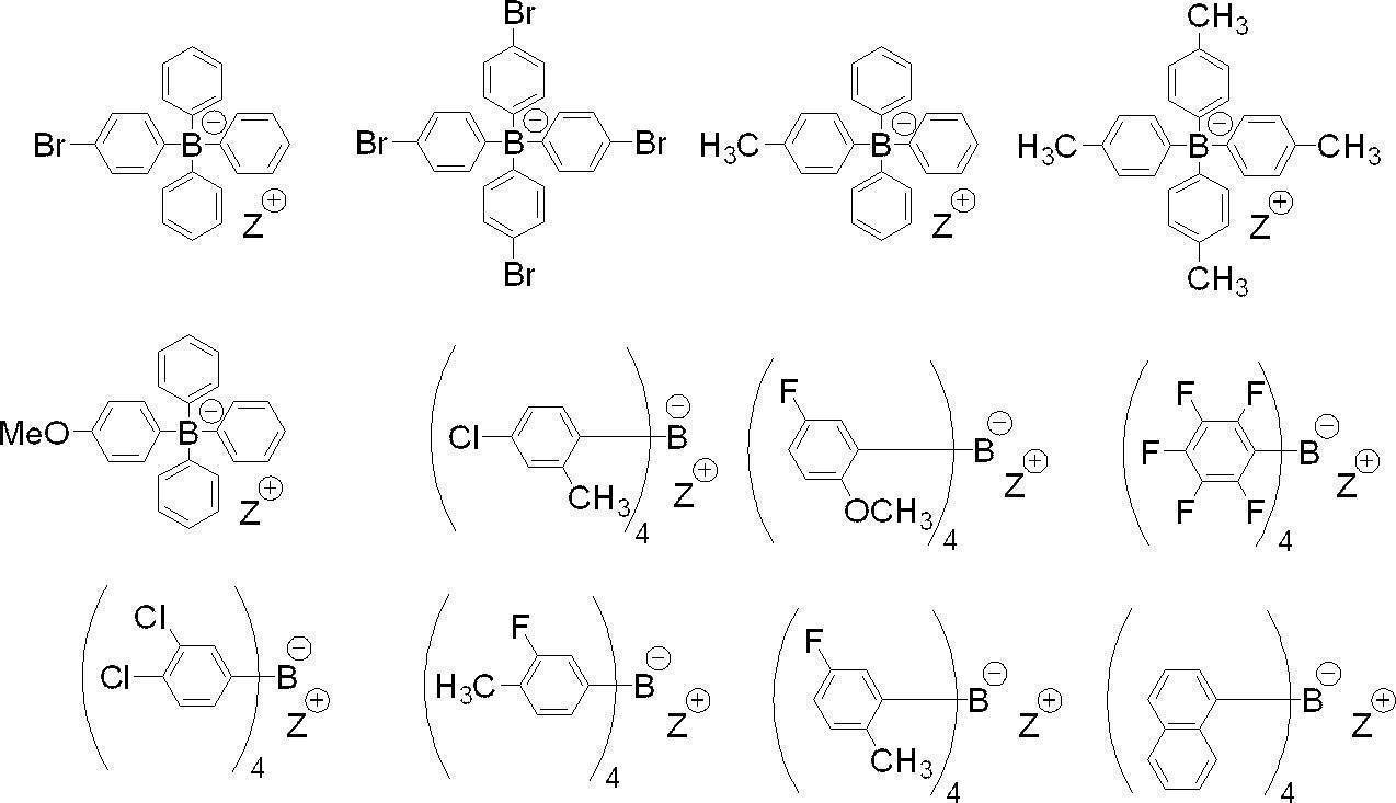
また、上記画像記録層は、上記電子供与型重合開始剤として、ボレート塩化合物を含むことが好ましく、上記電子供与型重合開始剤として、ボレート塩化合物を含み、かつ上記赤外線吸収剤AのHOMO-上記ボレート塩化合物のHOMOの値が、0.70eV以下であることがより好ましい。
上記各HOMOは、後述する方法にて算出するものとする。
電子供与型重合開始剤の含有量は、画像記録層の全質量に対し、0.01質量%~30質量%が好ましく、0.05質量%~25質量%がより好ましく、0.1質量%~20質量%が更に好ましい。
具体的には、例えば、上記オニウム塩化合物が、オニウムイオンと、上記電子供与型重合開始剤におけるアニオン(例えば、テトラフェニルボレートアニオン)との塩である態様が挙げられる。また、より好ましくは、上記ヨードニウム塩化合物におけるヨードニウムカチオン(例えば、ジ-p-トリルヨードニウムカチオン)と、上記電子供与型重合開始剤におけるボレートアニオンとが塩を形成した、ヨードニウムボレート塩化合物が挙げられる。
上記電子受容型重合開始剤と上記電子供与型重合開始剤とが塩を形成している態様の具体例を以下に示すが、本開示はこれらに限定されるものではない。
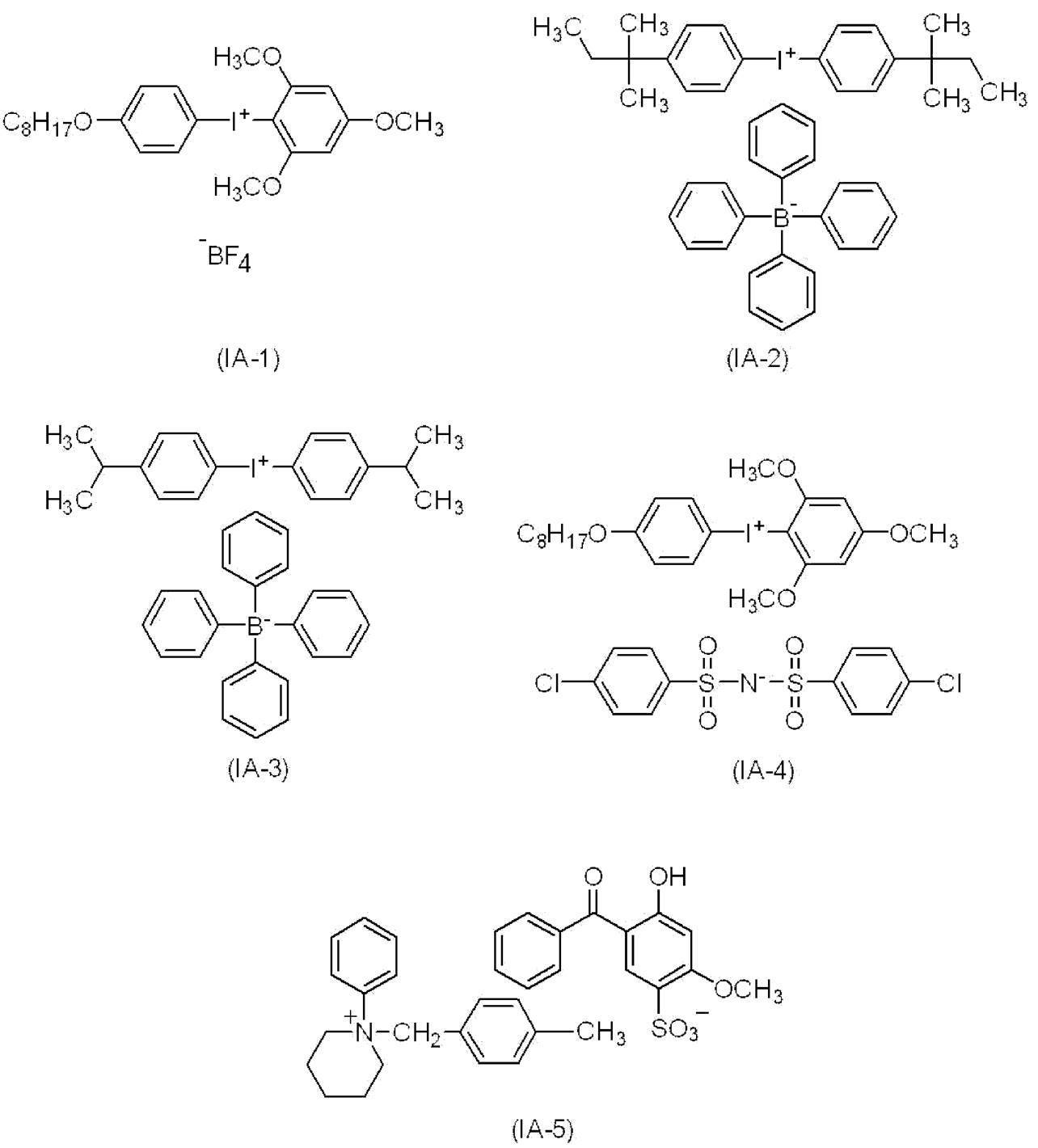
本開示における画像記録層は、上記電子供与型重合開始剤と、上記電子受容型重合開始剤と、上記赤外線吸収剤と、を含み、上記電子供与型重合開始剤のHOMOが-6.0eV以上であり、かつ、上記電子受容型重合開始剤のLUMOが-3.0eV以下であることが好ましい。
上記電子供与型重合開始剤のHOMO、及び、上記電子受容型重合開始剤のLUMOのより好ましい態様は、それぞれ上述の通りである。
本開示における画像記録層において、上記電子供与型重合開始剤と、上記赤外線吸収剤の少なくとも1種(好ましくは赤外線吸収剤A)と、上記電子受容型重合開始剤とは、例えば、下記化学式に記載のようにエネルギーの受け渡しを行っていると推測される。
そのため、上記電子供与型重合開始剤のHOMOが-6.0eV以上であり、かつ、上記電子受容型重合開始剤のLUMOが-3.0eV以下であれば、ラジカルの発生効率が向上するため、耐薬品性及びUV耐刷性により優れやすいと考えられる。

また、UV耐刷性及び耐薬品性の観点から、上記電子受容型重合開始剤のLUMO-上記赤外線吸収剤の少なくとも1種(好ましくは赤外線吸収剤A)のLUMOの値は、1.00eV以下であることが好ましく、0.700eV以下であることがより好ましい。また、同様の観点から、上記電子受容型重合開始剤のLUMO-上記赤外線吸収剤の少なくとも1種(好ましくは赤外線吸収剤A)のLUMOの値は、-0.200eV以上であることが好ましく、-0.100eV以上であることがより好ましい。
また、同様の観点から、上記電子受容型重合開始剤のLUMO-上記赤外線吸収剤の少なくとも1種(好ましくは赤外線吸収剤A)のLUMOの値は、1.00eV~-0.200eVであることが好ましく、0.700eV~-0.100eVであることがより好ましい。なお、マイナスの値は、上記赤外線吸収剤の少なくとも1種(好ましくは赤外線吸収剤A)のLUMOが、上記電子受容型重合開始剤のLUMOよりも高くなることを意味する。
上記画像記録層は、UV耐刷性の観点から、粒子を含むことが好ましい。
粒子としては、有機粒子であっても、無機粒子であってもよいが、UV耐刷性の観点から、有機粒子を含むことが好ましく、ポリマー粒子を含むことがより好ましい。
無機粒子としては、公知の無機粒子を用いることができ、シリカ粒子、チタニア粒子等の金属酸化物粒子を好適に用いることができる。
また、ポリマー粒子は、UV耐刷性、及び、機上現像性の観点から、熱可塑性樹脂粒子であることが好ましい。
熱可塑性樹脂粒子を構成するポリマーの具体例としては、エチレン、スチレン、塩化ビニル、アクリル酸メチル、アクリル酸エチル、メタクリル酸メチル、メタクリル酸エチル、塩化ビニリデン、アクリロニトリル、ビニルカルバゾール、ポリアルキレン構造を有するアクリレート又はメタクリレートなどのモノマーのホモポリマー若しくはコポリマー又はそれらの混合物を挙げることができる。好ましくは、ポリスチレン、スチレン及びアクリロニトリルを含む共重合体、又は、ポリメタクリル酸メチルを挙げることができる。熱可塑性樹脂粒子の平均粒径は0.01μm~3.0μmが好ましい。
上記多価フェノール化合物としては、フェノール性ヒドロキシ基を有するベンゼン環を複数有している化合物が好ましい。
上記活性水素を有する化合物としては、ポリオール化合物、又は、ポリアミン化合物が好ましく、ポリオール化合物がより好ましく、プロピレングリコール、グリセリン及びトリメチロールプロパンよりなる群から選ばれた少なくとも1種の化合物が更に好ましい。
分子中に2個以上のヒドロキシ基を有する多価フェノール化合物とイソホロンジイソシアネートとの付加物である多価イソシアネート化合物、及び、活性水素を有する化合物の反応により得られる樹脂の粒子としては、特開2012-206495号公報の段落0032~0095に記載のポリマー粒子が好ましく挙げられる。
上記疎水性主鎖としては、アクリル樹脂鎖が好ましく挙げられる。
上記ペンダントシアノ基の例としては、-[CH2CH(C≡N)]-又は-[CH2C(CH3)(C≡N)]-が好ましく挙げられる。
また、上記ペンダントシアノ基を有する構成ユニットは、エチレン系不飽和型モノマー、例えば、アクリロニトリル又はメタクリロニトリルから、又は、これらの組み合わせから容易に誘導することができる。
また、上記親水性ポリアルキレンオキシドセグメントにおけるアルキレンオキシドとしては、エチレンオキシド又はプロピレンオキシドが好ましく、エチレンオキシドがより好ましい。
上記親水性ポリアルキレンオキシドセグメントにおけるアルキレンオキシド構造の繰り返し数は、10~100であることが好ましく、25~75であることがより好ましく、40~50であることが更に好ましい。
疎水性主鎖を有し、i)上記疎水性主鎖に直接的に結合されたペンダントシアノ基を有する構成ユニット、及び、ii)親水性ポリアルキレンオキシドセグメントを含むペンダント基を有する構成ユニットの両方を含む樹脂の粒子としては、特表2008-503365号公報の段落0039~0068に記載のものが好ましく挙げられる。
上記親水性基としては、親水性を有する構造であれば、特に制限はないが、カルボキシ基等の酸基、ヒドロキシ基、アミノ基、シアノ基、ポリアルキレンオキシド構造等が挙げられる。
中でも、機上現像性、及び、UV耐刷性の観点から、ポリアルキレンオキシド構造が好ましく、ポリエチレンオキシド構造、ポリプロピレンオキシド構造、又は、ポリエチレン/プロピレンオキシド構造がより好ましい。
また、機上現像性、及び、機上現像時の現像カス抑制性の観点からは、上記ポリアルキレンオキシド構造として、ポリプロピレンオキシド構造を有することが好ましく、ポリエチレンオキシド構造及びポリプロピレンオキシド構造を有することがより好ましい。
また、上記親水性基としては、耐刷性、着肉性、及び、機上現像性の観点から、シアノ基を有する構成単位、又は、下記式Zで表される基を含むことが好ましく、下記式(AN)で表される構成単位、又は、下記式Zで表される基を含むことがより好ましく、下記式Zで表される基を含むことが特に好ましい。
*-Q-W-Y 式Z
式Z中、Qは二価の連結基を表し、Wは親水性構造を有する二価の基又は疎水性構造を有する二価の基を表し、Yは親水性構造を有する一価の基又は疎水性構造を有する一価の基を表し、W及びYのいずれかは親水性構造を有し、*は他の構造との結合部位を表す。
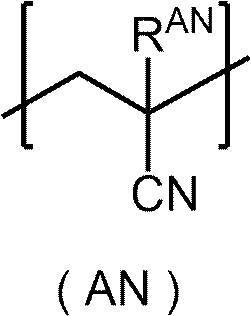
シアノ基は、通常、シアノ基を有する化合物(モノマー)を用いて、シアノ基を含む構成単位として樹脂に導入されることが好ましい。シアノ基を有する化合物としては、アクリロニトリル化合物が挙げられ、(メタ)アクリロニトリルが好適に挙げられる。
シアノ基を有する構成単位としては、アクリロニトリル化合物により形成される構成単位であることが好ましく、(メタ)アクリロニトリルにより形成される構成単位、すなわち、上記式(AN)で表される構成単位がより好ましい。
上記ポリマーが、シアノ基を有する構成単位を有するポリマーを含む場合、シアノ基を有する構成単位を有するポリマーにおけるシアノ基を有する構成単位、好ましくは上記式(AN)で表される構成単位の含有量は、UV耐刷性の観点から、シアノ基を有する構成単位を有するポリマーの全質量に対し、5質量%~90質量%であることが好ましく、20質量%~80質量%であることがより好ましく、30質量%~60質量%であることが特に好ましい。
また、上記式ZにおけるQは、アルキレン基、アリーレン基、エステル結合、アミド結合、又は、これらを2以上組み合わせた基であることが好ましく、フェニレン基、エステル結合、又は、アミド結合であることがより好ましい。
上記式ZのWにおける疎水性構造を有する二価の基は、-RWA-、-O-RWA-O-、-RWN-RWA-NRW-、-OC(=O)-RWA-O-、又は、-OC(=O)-RWA-O-であることが好ましい。なお、RWAはそれぞれ独立に、炭素数6~120の直鎖、分岐若しくは環状アルキレン基、炭素数6~120のハロアルキレン基、炭素数6~120のアリーレン基、炭素数6~120のアルカーリレン基(アルキルアリール基から水素原子を1つ除いた二価の基)、又は、炭素数6~120のアラルキレン基を表す。
上記式ZのYにおける疎水性構造を有する一価の基は、炭素数6~120の直鎖、分岐若しくは環状アルキル基、炭素数6~120のハロアルキル基、炭素数6~120のアリール基、炭素数7~120のアルカーリル基(アルキルアリール基)、炭素数7~120のアラルキル基、-ORWB、-C(=O)ORWB、又は、-OC(=O)RWBであることが好ましい。RWBは、炭素数6~20を有するアルキル基を表す。
更に、上記ポリマー粒子は、耐刷性の観点から、親水性基及び重合性基を有するポリマー粒子を含むことが好まし
上記重合性基は、カチオン重合性基であっても、ラジカル重合性基であってもよいが、反応性の観点からは、ラジカル重合性基であることが好ましい。
上記重合性基としては、重合可能な基であれば特に制限はないが、反応性の観点から、エチレン性不飽和基が好ましく、ビニルフェニル基(スチリル基)、(メタ)アクリロキシ基、又は、(メタ)アクリルアミド基がより好ましく、(メタ)アクリロキシ基が特に好ましい。
また、重合性基を有するポリマー粒子におけるポリマーは、重合性基を有する構成単位を有することが好ましい。
更に、高分子反応によりポリマー粒子表面に重合性基を導入してもよい。
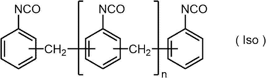
下記に示すように、上記式(Iso)で表されるイソシアネート化合物と水とを反応させると、水によりイソシアネート基の一部が加水分解し、アミノ基が生じ、生じたアミノ基とイソシアネート基とが反応し、ウレア結合が生成し、二量体が形成される。また、下記反応が繰り返され、ウレア結合を有する樹脂が形成される。
また、下記反応において、アルコール化合物、アミン化合物等のイソシアネート基と反応性を有する化合物(活性水素を有する化合物)を添加することにより、アルコール化合物、アミン化合物等の構造をウレア結合を有する樹脂に導入することもできる。
上記活性水素を有する化合物としては、上述したミクロゲルにおいて記載したものが好ましく挙げられる。
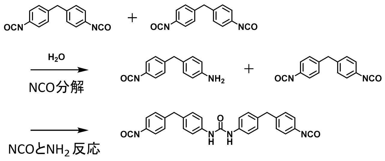

熱可塑性樹脂粒子に含まれる熱可塑性樹脂は、特に制限はなく、例えば、ポリエチレン、ポリスチレン、ポリ塩化ビニル、ポリ塩化ビニリデン、ポリ(メタ)アクリル酸メチル、ポリ(メタ)アクリル酸エチル、ポリ(メタ)アクリル酸ブチル、ポリアクリロニトリル、ポリ酢酸ビニル、それらの共重合体等が挙げられる。熱可塑性樹脂はラテックス状態であってもよい。
本開示に係る熱可塑性樹脂は、後述する露光工程において生成された熱により、熱可塑性樹脂が溶融又は軟化することで、記録層を形成する疎水性の膜の一部又は全部を形成する樹脂であることが好ましい。
芳香族ビニル化合物としては、芳香環にビニル基が結合した構造を有する化合物であればよいが、スチレン化合物、ビニルナフタレン化合物等が挙げられ、スチレン化合物が好ましく、スチレンがより好ましい。
スチレン化合物としては、スチレン、p-メチルスチレン、p-メトキシスチレン、β-メチルスチレン、p-メチル-β-メチルスチレン、α-メチルスチレン、及びp-メトキシ-β-メチルスチレン等が挙げられ、スチレンが好ましく挙げられる。
ビニルナフタレン化合物としては、1-ビニルナフタレン、メチル-1-ビニルナフタレン、β-メチル-1-ビニルナフタレン、4-メチル-1-ビニルナフタレン、4-メトキシ-1-ビニルナフタレン等が挙げられ、1-ビニルナフタレンが好ましく挙げられる。

式A1中、RA1及びRA2はそれぞれ独立に、水素原子又は炭素数1~4のアルキル基であることが好ましく、水素原子又はメチル基であることがより好ましく、いずれも水素原子であることが更に好ましい。
式A1中、Arはベンゼン環又はナフタレン環であることが好ましく、ベンゼン環であることがより好ましい。
式A1中、RA3はアルキル基又はアルコキシ基であることが好ましく、炭素数1~4のアルキル基又は炭素数1~4のアルコキシ基であることがより好ましく、メチル基又はメトキシ基であることが更に好ましい。
式A1中、RA3が複数存在する場合、複数のRA3は同一であってもよいし、それぞれ異なっていてもよい。
式A1中、nは0~2の整数であることが好ましく、0又は1であることがより好ましく、0であることが更に好ましい。
シアノ基は、通常、シアノ基を有する化合物(モノマー)を用いて、シアノ基を含む構成単位として樹脂Aに導入されることが好ましい。シアノ基を有する化合物としては、アクリロニトリル化合物が挙げられ、(メタ)アクリロニトリルが好適に挙げられる。
シアノ基を有する構成単位としては、アクリロニトリル化合物により形成される構成単位であることが好ましく、(メタ)アクリロニトリルにより形成される構成単位がより好ましい。
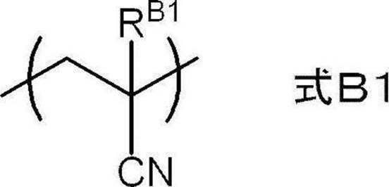
式B1中、RB1は水素原子又は炭素数1~4のアルキル基であることが好ましく、水素原子又はメチル基であることがより好ましく、水素原子であることが更に好ましい。
N-ビニル複素環化合物としては、例えば、N-ビニルピロリドン、N-ビニルカルバゾール、N-ビニルピロール、N-ビニルフェノチアジン、N-ビニルコハク酸イミド、N-ビニルフタルイミド、N-ビニルカプロラクタム、及びN-ビニルイミダゾールが挙げられ、N-ビニルピロリドンが好ましい。

式C1中、ArNにより表される複素環構造は、ピロリドン環、カルバゾール環、ピロール環、フェノチアジン環、スクシンイミド環、フタルイミド環、カプロラクタム環、及びイミダゾール環であることが好ましく、ピロリドン環であることがより好ましい。
また、ArNにより表される複素環構造は公知の置換基を有していてもよい。
具体的には、熱可塑性樹脂における酸性基を有する構成単位の含有量は、20質量%以下であることが好ましく、10質量%以下であることがより好ましく、5質量%以下であることが更に好ましい。上記含有量の下限は特に限定されず、0質量%であってもよい。
また、熱可塑性樹脂の酸価は、160mgKOH/g以下であることが好ましく、80mgKOH/g以下であることがより好ましく、40mgKOH/g以下であることが更に好ましい。上記酸価の下限は特に限定されず、0mgKOH/gであってもよい。
本開示において、酸価はJIS K0070:1992に準拠した測定法により求められる。
上記疎水性基としては、アルキル基、アリール基、アラルキル基等が挙げられる。
疎水性基を含む構成単位としては、アルキル(メタ)アクリレート化合物、アリール(メタ)アクリレート化合物、又は、アラルキル(メタ)アクリレート化合物により形成される構成単位が好ましく、アルキル(メタ)アクリレート化合物により形成される構成単位がより好ましい。
上記アルキル(メタ)アクリレート化合物におけるアルキル基の炭素数は、1~10であることが好ましい。上記アルキル基は直鎖状であっても分岐鎖状であってもよく、環状構造を有していてもよい。アルキル(メタ)アクリレート化合物としては、メチル(メタ)アクリレート、エチル(メタ)アクリレート、プロピル(メタ)アクリレート、シクロヘキシル(メタ)アクリレート、2-エチルヘキシル(メタ)アクリレート、ジシクロペンタニル(メタ)アクリレート等が挙げられる。
上記アリール(メタ)アクリレート化合物におけるアリール基の炭素数は、6~20であることが好ましく、フェニル基であることがより好ましい。また、上記アリール基は公知の置換基を有していてもよい。アリール(メタ)アクリレート化合物としては、フェニル(メタ)アクリレートが好ましく挙げられる。
上記アラルキル(メタ)アクリレート化合物におけるアルキル基の炭素数は、1~10であることが好ましい。上記アルキル基は直鎖状であっても分岐鎖状であってもよく、環状構造を有していてもよい。また、上記アラルキル(メタ)アクリレート化合物におけるアリール基の炭素数は、6~20であることが好ましく、フェニル基であることがより好ましい。アラルキル(メタ)アクリレート化合物としては、ベンジル(メタ)アクリレートが好ましく挙げられる。
親水性基としては、親水性を有する構造であれば、特に制限はないが、カルボキシ基等の酸基、ヒドロキシ基、アミノ基、シアノ基、ポリアルキレンオキシド構造等が挙げられる。
上記親水性基としては、UV耐刷性及び機上現像性の観点から、ポリアルキレンオキシド構造を有する基、ポリエステル構造を有する基、又は、スルホン酸基であることが好ましく、ポリアルキレンオキシド構造を有する基、又は、スルホン酸基であることがより好ましく、ポリアルキレンオキシド構造を有する基であることが更に好ましい。
また、機上現像性の観点からは、上記親水性基の中でもポリアルキレンオキシド構造として、ポリプロピレンオキシド構造を有することが好ましく、ポリエチレンオキシド構造及びポリプロピレンオキシド構造を有することがより好ましい。
上記ポリアルキレンオキシド構造におけるアルキレンオキシド構造の数は、機上現像性の観点から、2以上であることが好ましく、5以上であることがより好ましく、5~200であることが更に好ましく、8~150であることが特に好ましい。
上記親水性基としては、-OH、-CN、-CONR1R2、-NR2COR1(R1及びR2はそれぞれ独立して水素原子、アルキル基、アルケニル基、又は、アリール基を表す。R1とR2とは結合して環を形成してもよい。)-NR3R4、-N+R3R4R5X-(R3~R5は、それぞれ独立して炭素数1~8のアルキル基を表し、X-はカウンターアニオンを表す)、下記式POにより表される基、上記の熱可塑性樹脂粒子に含まれる熱可塑性樹脂が好ましく有する親水性基等が挙げられる。
これら親水性基の中でも、-CONR1R2又は式POにより表される基が好ましく、式POにより表される基がより好ましい。
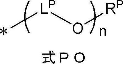
式PO中、LPはそれぞれ独立に、エチレン基、1-メチルエチレン基又は2-メチルエチレン基であることが好ましく、エチレン基であることがより好ましい。
式PO中、RPは水素原子又は炭素数1~18のアルキル基であることが好ましく、水素原子又は炭素数1~10のアルキル基であることがより好ましく、水素原子又は炭素数1~4のアルキル基であることが更に好ましく、水素原子又はメチル基であることが特に好ましい。
式PO中、nは1~10の整数が好ましく、1~4の整数がより好ましい。
アクリルアミド化合物としては、例えば、(メタ)アクリルアミド、N-メチル(メタ)アクリルアミド、N-エチル(メタ)アクリルアミド、N-プロピル(メタ)アクリルアミド、N-ブチル(メタ)アクリルアミド、N,N’-ジメチル(メタ)アクリルアミド、N,N’-ジエチル(メタ)アクリルアミド、N-ヒドロキシエチル(メタ)アクリルアミド、N-ヒドロキシプロピル(メタ)アクリルアミド、N-ヒドロキシブチル(メタ)アクリルアミド等が挙げられる。
ビニルエーテル化合物としては、例えば、メチルビニルエーテル、エチルビニルエーテル、プロピルビニルエーテル、n-ブチルビニルエーテル、tert-ブチルビニルエーテル、2-エチルヘキシルビニルエーテル、n-ノニルビニルエーテル、ラウリルビニルエーテル、シクロヘキシルビニルエーテル、シクロヘキシルメチルビニルエーテル、4-メチルシクロヘキシルメチルビニルエーテル、ベンジルビニルエーテル、ジシクロペンテニルビニルエーテル、2-ジシクロペンテノキシエチルビニルエーテル、メトキシエチルビニルエーテル、エトキシエチルビニルエーテル、ブトキシエチルビニルエーテル、メトキシエトキシエチルビニルエーテル、エトキシエトキシエチルビニルエーテル、メトキシポリエチレングリコールビニルエーテル、テトラヒドロフルフリルビニルエーテル、2-ヒドロキシエチルビニルエーテル、2-ヒドロキシプロピルビニルエーテル、4-ヒドロキシブチルビニルエーテル、4-ヒドロキシメチルシクロヘキシルメチルビニルエーテル、ジエチレングリコールモノビニルエーテル、ポリエチレングリコールビニルエーテル、クロロエチルビニルエーテル、クロロブチルビニルエーテル、クロロエトキシエチルビニルエーテル、フェニルエチルビニルエーテル、フェノキシポリエチレングリコールビニルエーテル、などが挙げられる。
熱可塑性樹脂粒子が2種以上の熱可塑性樹脂を含む場合には、後述するFOX式により求められた値を、熱可塑性樹脂のガラス転移温度という。
具体的な測定方法は、JIS K 7121(1987年)又はJIS K 6240(2011年)に記載の方法に順じて行なう。本明細書におけるガラス転移温度は、補外ガラス転移開始温度(以下、Tigと称することがある)を用いている。
ガラス転移温度の測定方法をより具体的に説明する。
ガラス転移温度を求める場合、予想される樹脂のTgより約50℃低い温度にて装置が安定するまで保持した後、加熱速度:20℃/分で、ガラス転移が終了した温度よりも約30℃高い温度まで加熱し,示差熱分析(DTA)曲線又はDSC曲線を作成する。
補外ガラス転移開始温度(Tig)、すなわち、本明細書におけるガラス転移温度Tgは、DTA曲線又はDSC曲線における低温側のベースラインを高温側に延長した直線と、ガラス転移の階段状変化部分の曲線の勾配が最大になる点で引いた接線との交点の温度として求める。
1つ目の熱可塑性樹脂のTgをTg1(K)、熱可塑性樹脂粒子における熱可塑性樹脂成分の合計質量に対する1つ目の熱可塑性樹脂の質量分率をW1とし、2つ目のTgをTg2(K)とし、熱可塑性樹脂粒子における熱可塑性樹脂成分の合計質量に対する2つ目の樹脂の質量分率をW2としたときに、熱可塑性樹脂粒子のTg0(K)は、以下のFOX式にしたがって推定することが可能である。
FOX式:1/Tg0=(W1/Tg1)+(W2/Tg2)
また、熱可塑性樹脂粒子が3種の樹脂を含むか、含まれる熱可塑性樹脂種の異なる3種の熱可塑性樹脂粒子が前処理液に含有される場合、熱可塑性樹脂粒子のTgは、n個目の樹脂のTgをTgn(K)、熱可塑性樹脂粒子における樹脂成分の合計質量に対するn個目の樹脂の質量分率をWnとしたときに、上記と同様、以下の式にしたがって推定することが可能である。
FOX式:1/Tg0=(W1/Tg1)+(W2/Tg2)+(W3/Tg3)・・・+(Wn/Tgn)
例えば、スチレン化合物と、アクリロニトリル化合物と、必要に応じて上記N-ビニル複素環化合物、上記エチレン性不飽和基を有する構成単位の形成に用いられる化合物、上記酸性基を有する構成単位の形成に用いられる化合物、上記疎水性基を有する構成単位の形成に用いられる化合物、及び、上記その他の構成単位の形成に用いられる化合物よりなる群から選ばれた少なくとも1種の化合物、とを、公知の方法により重合することにより得られる。
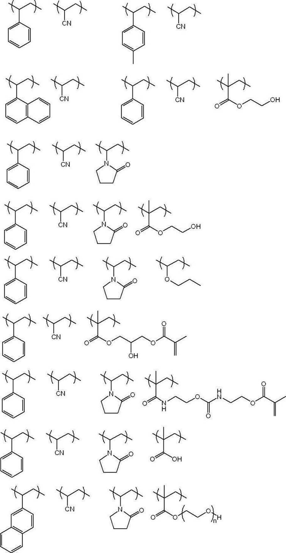
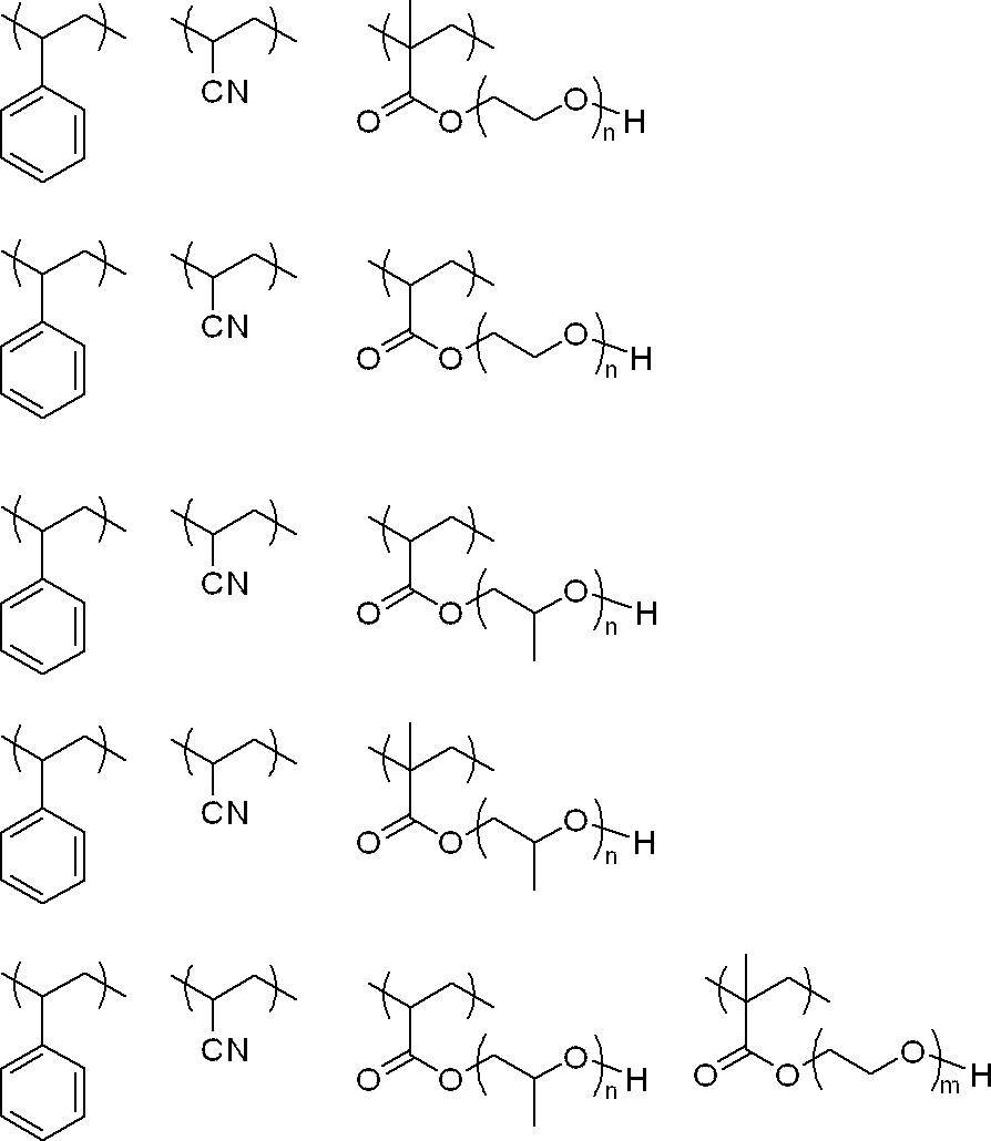
また、上記具体例に示す各化合物の重量平均分子量は、上述の熱可塑性樹脂の重量平均分子量の好ましい範囲に従って、適宜変更可能である。
本開示における上記粒子の平均一次粒径は、光散乱法により測定するか、又は、粒子の電子顕微鏡写真を撮影し、写真上で粒子の粒径を総計で5,000個測定し、平均値を算出するものとする。なお、非球形粒子については写真上の粒子面積と同一の粒子面積を有する球形粒子の粒径値を粒径とする。
また、本開示における平均粒径は、特に断りのない限り、体積平均粒径であるものとする。
また、上記画像記録層における粒子、特にポリマー粒子の含有量は、機上現像性、及び、UV耐刷性の観点から、上記画像記録層の全質量に対し、5質量%~90質量%が好ましく、10質量%~90質量%であることがより好ましく、20質量%~90質量%であることが更に好ましく、50質量%~90質量%であることが特に好ましい。
また、上記画像記録層におけるポリマー粒子の含有量は、機上現像性、及び、UV耐刷性の観点から、上記画像記録層の分子量3,000以上の成分の全質量に対し、20質量%~100質量%が好ましく、35質量%~100質量%であることがより好ましく、50質量%~100質量%であることが更に好ましく、80質量%~100質量%であることが特に好ましい。
画像記録層は、バインダーポリマーを含んでいてもよい。
上記熱可塑性樹脂粒子、及び、上記ポリマー粒子は、上記他のバインダーポリマーに該当しない。すなわち、他のバインダーポリマーは、粒子形状ではない重合体である。
他のバインダーポリマーとしては、(メタ)アクリル樹脂、ポリビニルアセタール樹脂、又は、ポリウレタン樹脂が好ましい。
機上現像用バインダーポリマーとしては、アルキレンオキシド鎖を有するバインダーポリマーが好ましい。アルキレンオキシド鎖を有するバインダーポリマーは、ポリ(アルキレンオキシド)部位を主鎖に有していても側鎖に有していてもよい。また、ポリ(アルキレンオキシド)を側鎖に有するグラフトポリマーでも、ポリ(アルキレンオキシド)含有繰返し単位で構成されるブロックと(アルキレンオキシド)非含有繰返し単位で構成されるブロックとのブロックコポリマーでもよい。
ポリ(アルキレンオキシド)部位を主鎖に有する場合は、ポリウレタン樹脂が好ましい。ポリ(アルキレンオキシド)部位を側鎖に有する場合の主鎖のポリマーとしては、(メタ)アクリル樹脂、ポリビニルアセタール樹脂、ポリウレタン樹脂、ポリウレア樹脂、ポリイミド樹脂、ポリアミド樹脂、エポキシ樹脂、ポリスチレン樹脂、ノボラック型フェノール樹脂、ポリエステル樹脂、合成ゴム、天然ゴムが挙げられ、特に(メタ)アクリル樹脂が好ましい。
重合性基としては、(メタ)アクリル基、ビニル基、アリル基、ビニルフェニル基(スチリル基)などのエチレン性不飽和基やエポキシ基等が好ましく、(メタ)アクリル基、ビニル基、ビニルフェニル基(スチリル基)が重合反応性の観点でより好ましく、(メタ)アクリル基が特に好ましい。これらの基は高分子反応や共重合によってポリマーに導入することができる。例えば、カルボキシ基を側鎖に有するポリマーとグリシジルメタクリレートとの反応、あるいはエポキシ基を有するポリマーとメタクリル酸などのエチレン性不飽和基含有カルボン酸との反応を利用できる。これらの基は併用してもよい。
また、バインダーポリマーのガラス転移温度の上限としては、画像記録層への水の浸み込みやすさの観点から、200℃が好ましく、120℃以下がより好ましい。
特に、ポリビニルアルコールのヒドロキシ基を、ブチルアルデヒドでアセタール化(即ち、ブチラール化)したポリビニルブチラールが好ましい。
ポリビニルアセタールは、ポリビニルアルコールのヒドロキシ基をアルデヒドにてアセタール化することで、下記(a)で表される構成単位を含むことが好ましい。
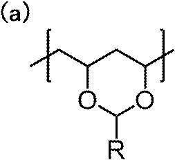
Rとしては、水素原子、アルキル基等の他、後述するエチレン性不飽和基が挙げられる。
なお、アセタール化度とは、アセタール基が結合しているエチレン基量(上記(a)で表される構成単位に含まれる主鎖のエチレン基量)を、主鎖の全エチレン基量で除して求めたモル分率を百分率で示した値である。
また、後述のポリビニルアセタールの各構成単位の含有量においても、同様である。
ここで、ポリビニルアセタールが有するエチレン性不飽和基としては特に制限はなく、反応性、機上現像性、及び耐刷性の観点から、ビニルフェニル基(スチリル基)、ビニルエステル基、ビニルエーテル基、アリル基、(メタ)アクリロキシ基、及び(メタ)アクリルアミド基からなる群より選ばれた少なくとも1種の基であることがより好ましく、ビニル基、アリル基、(メタ)アクリロキシ基等が好ましい。
エチレン性不飽和基を有する構成単位としては、上述のアセタール環を有する構成単位であってもよいし、アセタール環を有する構成単位以外の構成単位であってもよい。
中でも、露光時の架橋密度増加の観点から、ポリビニルアセタールは、アセタール環にエチレン性不飽和基が導入された化合物であることが好ましい。即ち、上述の(a)で表される構成単位において、Rにエチレン性不飽和基を有することが好ましい。
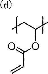
ヒドロキシ基を有する構成単位としては、下記(b)で表される構成単位が挙げられる。
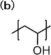
その他の構成単位としては、例えば、アセチル基を有する構成単位、具体的には、以下(c)で表される構成単位が挙げられる。

即ち、1H NMR測定によって、アセタールのメチル又はメチレン部位、アクリレート基のメチル部位、水酸基及びアセチル基のメチル部位のプロトンピーク面積比からmol含有率を算出する。
ここで、本開示における「溶解度パラメータ(単位:(MPa)1/2)」は、ハンセン(Hansen)溶解度パラメータを用いるものとする。
ハンセン(Hansen)溶解度パラメータは、ヒルデブランド(Hildebrand)によって導入された溶解度パラメータを、分散項δd、極性項δp、水素結合項δhの3成分に分割し、3次元空間に表したものであるが、本開示においては溶解度パラメータ(以降、SP値ともいう)をδ(単位:(MPa)1/2)で表し、下記式を用いて算出される値を用いる。
δ(MPa)1/2=(δd2+δp2+δh2)1/2
なお、この分散項δd、極性項δp、及び水素結合項δhは、ハンセンやその研究後継者らにより多く求められており、Polymer Handbook (fourth edition)、VII-698~711に詳しく掲載されている。また、ハンセンの溶解度パラメータの値の詳細については、Charles M.Hansen著の文献「Hansen Solubility Parameters; A Users Handbook (CRC Press,2007)」に記載されている。
本開示において、化合物の部分構造におけるハンセン溶解度パラメータは、コンピュータソフトウェア「Hansen Solubility Parameters in Practice(HSPiP ver.4.1.07)」を用いることにより、その化学構造から推算した値を用いることもできる。
また、本開示においては、化合物が付加重合型、重縮合型等のポリマーである場合は、モノマー単位ごとのSP値をモル分率で掛け合わせた総量で示し、化合物がモノマー単位を有しない低分子化合物である場合は、化合物全体のSP値とする。
なお、本開示において、ポリマーのSP値は、ポリマーの分子構造からPolymer Handbook (fourth edition)に記載のHoy法により計算してもよい。
下記構造中、「l」は50mol%~90mol%であり、「m」は0.5mol%~10質量%であり、「n」は5mol%~50mol%であり、「o」は1mol%~15mol%である。
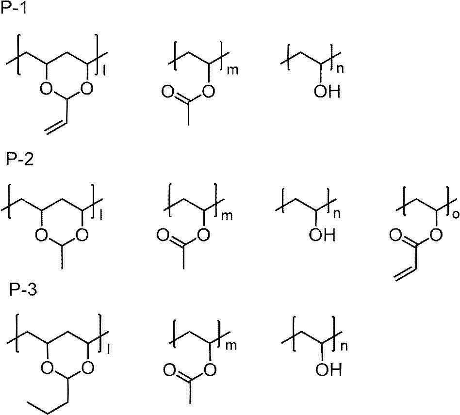
ポリビニルアセタールの市販品としては、積水化学工業(株)のエスレックシリーズ(具体的には、エスレック BX-L,BX-1,BX-5,BL-7Z,BM-1,BM-5,BH-6,BH-3等)が挙げられる。
バインダーポリマーは、画像記録層中に任意な量で含有させることができるが、バインダーポリマーの含有量は、画像記録層の全質量に対して、1質量%~90質量%であることが好ましく、5質量%~80質量%であることがより好ましい。
また、本開示における画像記録層が他のバインダーポリマーを含む場合、上記熱可塑性樹脂粒子と他のバインダーポリマーとの合計質量に対する他のバインダーポリマーの含有量は、0質量%を超え99質量%以下であることが好ましく、20質量%~95質量%であることがより好ましく、40質量%~90質量%であることが更に好ましい。
上記画像記録層は、発色剤を含むことが好ましく、酸発色剤を含むことがより好ましい。
本開示で用いられる「発色剤」とは、光や酸等の刺激により発色又は消色し画像記録層の色を変化させる性質を有する化合物を意味し、また、「酸発色剤」とは、電子受容性化合物(例えば酸等のプロトン)を受容した状態で加熱することにより、発色又は消色し画像記録層の色を変化させる性質を有する化合物を意味する。酸発色剤としては、特に、ラクトン、ラクタム、サルトン、スピロピラン、エステル、アミド等の部分骨格を有し、電子受容性化合物と接触した時に、速やかにこれらの部分骨格が開環若しくは開裂する無色の化合物が好ましい。
発色後の色素の色相としては、可視性の観点から、緑、青又は黒であることが好ましい。
上記ロイコ色素としては、ロイコ構造を有する色素であれば、特に制限はないが、スピロ構造を有することが好ましく、スピロラクトン環構造を有することがより好ましい。
また、上記ロイコ色素としては、発色性、及び、露光部の視認性の観点から、フタリド構造又はフルオラン構造を有するロイコ色素であることが好ましい。
更に、上記フタリド構造又はフルオラン構造を有するロイコ色素は、発色性、及び、露光部の視認性の観点から、下記式(Le-1)~式(Le-3)のいずれかで表される化合物であることが好ましく、下記式(Le-2)で表される化合物であることがより好ましい。

また、上記ERGにおける電子供与性基としては、発色性、及び、露光部の視認性の観点から、少なくとも1つのオルト位に置換基を有するアリール基又は少なくとも1つのオルト位に置換基を有するヘテロアリール基を有する二置換アミノ基であることが好ましく、少なくとも1つのオルト位に置換基を有し、かつパラ位に電子供与性基を有するフェニル基を有する二置換アミノ基であることがより好ましく、少なくとも1つのオルト位に置換基を有し、かつパラ位に電子供与性基を有するフェニル基とアリール基又はヘテロアリール基とを有するアミノ基であることが更に好ましく、少なくとも1つのオルト位に置換基を有し、かつパラ位に電子供与性基を有するフェニル基と電子供与性基を有するアリール基又は電子供与性基を有するヘテロアリール基とを有するアミノ基であることが特に好ましい。
なお、本開示において、フェニル基以外のアリール基又はヘテロアリール基におけるオルト位は、アリール基又はヘテロアリール基の他の構造との結合位置を1位とした場合の上記1位の隣の結合位置(例えば、2位等)を言うものとする。
更に、上記アリール基又はヘテロアリール基が有する電子供与性基としては、発色性、及び、露光部の視認性の観点から、アミノ基、アルキルアミノ基、アリールアミノ基、ヘテロアリールアミノ基、ジアルキルアミノ基、モノアルキルモノアリールアミノ基、モノアルキルモノヘテロアリールアミノ基、ジアリールアミノ基、ジヘテロアリールアミノ基、モノアリールモノヘテロアリールアミノ基、アルコキシ基、アリーロキシ基、ヘテロアリーロキシ基、又は、アルキル基であることが好ましく、アルコキシ基、アリーロキシ基、ヘテロアリーロキシ基、又は、アルキル基であることがより好ましく、アルコキシ基であることが特に好ましい。
式(Le-2)又は式(Le-3)におけるX5~X10はそれぞれ独立に、発色性、及び、露光部の視認性の観点から、水素原子、ハロゲン原子、アルキル基、アリール基、アミノ基、アルキルアミノ基、アリールアミノ基、ヘテロアリールアミノ基、ジアルキルアミノ基、モノアルキルモノアリールアミノ基、モノアルキルモノヘテロアリールアミノ基、ジアリールアミノ基、ジヘテロアリールアミノ基、モノアリールモノヘテロアリールアミノ基、ヒドロキシ基、アルコキシ基、アリーロキシ基、ヘテロアリーロキシ基、アシル基、アルコキシカルボニル基、アリーロキシカルボニル基、ヘテロアリーロキシカルボニル基又はシアノ基であることが好ましく、水素原子、ハロゲン原子、アルキル基、アリール基、アルコキシ基、又は、アリーロキシ基であることがより好ましく、水素原子、ハロゲン原子、アルキル基、又は、アリール基であることが更に好ましく、水素原子であることが特に好ましい。
式(Le-1)~式(Le-3)におけるY1及びY2は、発色性、及び、露光部の視認性の観点から、少なくとも1方がCであることが好ましく、Y1及びY2の両方がCであることがより好ましい。
式(Le-1)~式(Le-3)におけるRa1は、発色性、及び、露光部の視認性の観点から、アルキル基又はアルコキシ基であることが好ましく、アルコキシ基であることがより好ましく、メトキシ基であることが特に好ましい。
式(Le-1)~式(Le-3)におけるRb1~Rb4はそれぞれ独立に、発色性、及び、露光部の視認性の観点から、水素原子又はアルキル基であることが好ましく、アルキル基であることがより好ましく、メチル基であることが特に好ましい。
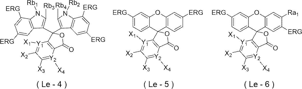
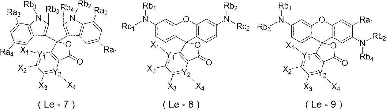
式(Le-7)又は式(Le-9)におけるRa1~Ra4はそれぞれ独立に、発色性、及び、露光部の視認性の観点から、アルキル基又はアルコキシ基であることが好ましく、アルコキシ基であることがより好ましく、メトキシ基であることが特に好ましい。
式(Le-7)~式(Le-9)におけるRb1~Rb4はそれぞれ独立に、発色性、及び、露光部の視認性の観点から、水素原子、アルキル基又はアルコキシ基が置換したアリール基であることが好ましく、アルキル基であることがより好ましく、メチル基であることが特に好ましい。
式(Le-8)におけるRc1及びRc2はそれぞれ独立に、発色性、及び、露光部の視認性の観点から、フェニル基、又は、アルキルフェニル基であることが好ましく、フェニル基であることがより好ましい。
また、式(Le-8)におけるRc1及びRc2はそれぞれ独立に、発色性、及び、露光部の視認性の観点から、少なくとも1つのオルト位に置換基を有するアリール基、又は、少なくとも1つのオルト位に置換基を有するヘテロアリール基であることが好ましく、少なくとも1つのオルト位に置換基を有するアリール基であることがより好ましく、少なくとも1つのオルト位に置換基を有するフェニル基であることが更に好ましく、少なくとも1つのオルト位に置換基を有し、かつパラ位に電子供与性基を有するフェニル基であることが特に好ましい。Rc1及びRc2における上記置換基としては、後述する置換基が挙げられる。
また、式(Le-8)において、発色性、及び、露光部の視認性の観点から、X1~X4が水素原子であり、Y1及びY2がCであることが好ましい。
更に、式(Le-8)において、発色性、及び、露光部の視認性の観点から、Rb1及びRb2がそれぞれ独立に、アルキル基又はアルコキシ基が置換したアリール基であることが好ましい。
更にまた、式(Le-8)において、発色性、及び、露光部の視認性の観点から、Rb1及びRb2がそれぞれ独立に、アリール基又はヘテロアリール基であることが好ましく、アリール基であることがより好ましく、電子供与性基を有するアリール基であることが更に好ましく、パラ位に電子供与性基を有するフェニル基であることが特に好ましい。
また、Rb1、Rb2、Rc1及びRc2における上記電子供与性基としては、発色性、及び、露光部の視認性の観点から、アミノ基、アルキルアミノ基、アリールアミノ基、ヘテロアリールアミノ基、ジアルキルアミノ基、モノアルキルモノアリールアミノ基、モノアルキルモノヘテロアリールアミノ基、ジアリールアミノ基、ジヘテロアリールアミノ基、モノアリールモノヘテロアリールアミノ基、アルコキシ基、アリーロキシ基、ヘテロアリーロキシ基、又は、アルキル基であることが好ましく、アルコキシ基、アリーロキシ基、ヘテロアリーロキシ基、又は、アルキル基であることがより好ましく、アルコキシ基であることが特に好ましい。
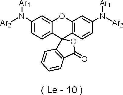
式(Le-10)におけるAr2は、式(Le-7)~式(Le-9)におけるRc1及びRc2と同義であり、好ましい態様も同様である。

式(Le-11)におけるn11は、1~3の整数であることが好ましく、1又は2であることがより好ましい。
また、式(Le-1)~式(Le-9)又は式(Le-11)におけるアルキル基の炭素数は、1~20であることが好ましく、1~8であることがより好ましく、1~4であることが更に好ましく、1又は2であることが特に好ましい。
式(Le-1)~式(Le-11)におけるアリール基の炭素数は、6~20であることが好ましく、6~10であることがより好ましく、6~8であることが特に好ましい。
式(Le-1)~式(Le-11)におけるアリール基として具体的には、置換基を有していてもよい、フェニル基、ナフチル基、アントラセニル基、及び、フェナントレニル基等が挙げられる。
式(Le-1)~式(Le-11)におけるヘテロアリール基として具体的には、置換基を有していてもよい、フリル基、ピリジル基、ピリミジル基、ピラゾイル基、及び、チオフェニル基等が挙げられる。

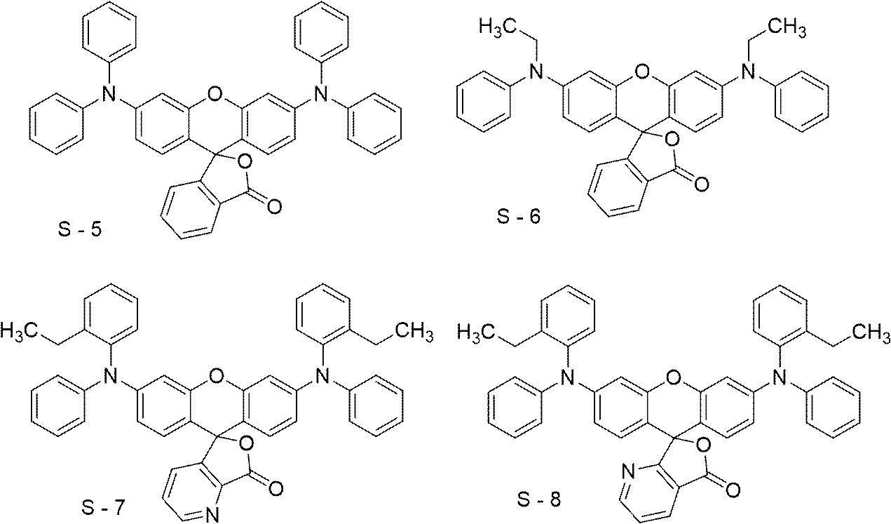
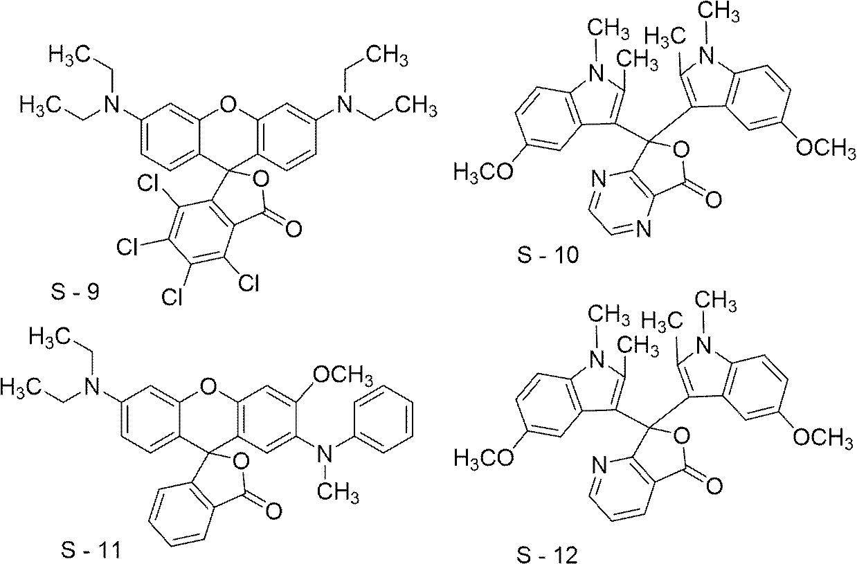
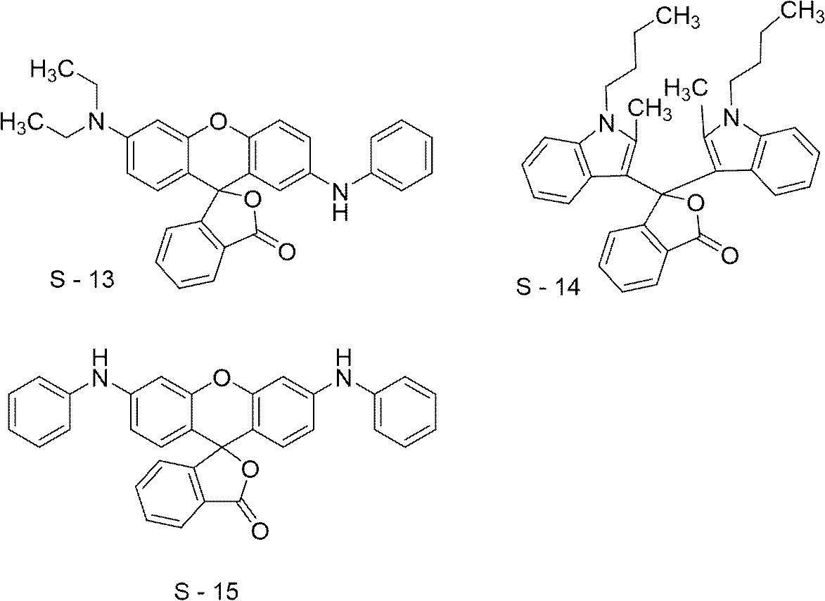
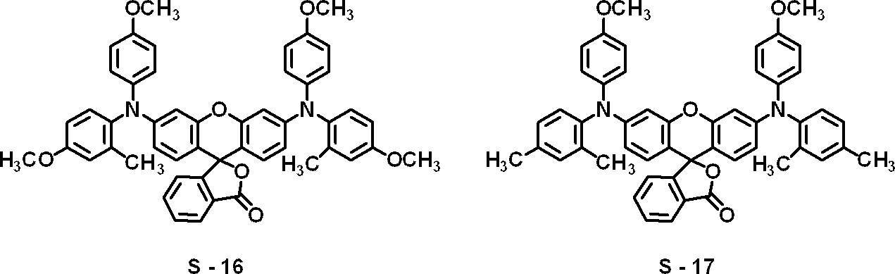
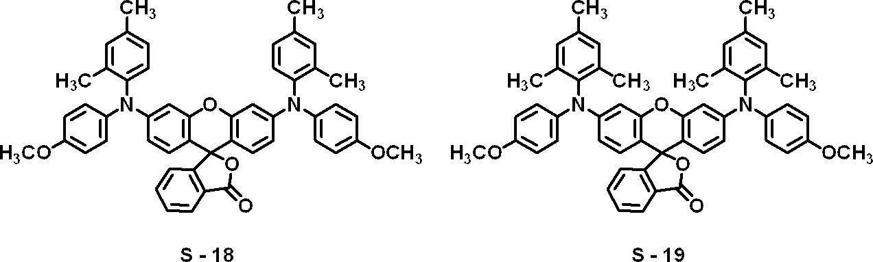


発色剤の含有量は、画像記録層の全質量に対し、0.5質量%~10質量%であることが好ましく、1質量%~5質量%であることがより好ましい。
計算プログラムはGaussian16を用い、計算レベルは密度汎関数法(B3LYP/6-31+G**)、溶媒効果はSCRF法(溶媒:Methanol)として、水素引き抜きによる成長ラジカルとの反応について、反応物と生成物のエンタルピーを各々計算し、両者の差をとることにより、反応エンタルピー計算を実施する。
計算を実行して最適化された構造のエネルギー(単位:hartree)から、反応物の生成エンタルピー(成長ラジカルとLeucoDye-Hのエネルギーの和)、及び、生成物の生成エンタルピー(水素付加された成長ラジカルとLeucoDye-radicalのエネルギーの和)を求め、生成物の生成エンタルピーから反応物の生成エンタルピーを差し引いた値を水素引抜きエンタルピーとする。単位は、1hartree=627.51kcal/molとして換算する。

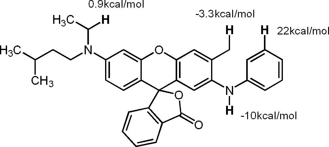
複数の合成ルートによって、所望の色素化合物を得ることが可能である。
同様にして、他のロイコ色素の合成も実施することができる。
なお、パラジウム(Pd)触媒及びその配位子は、適宜適切に市販されている触媒及び配位子を選択することで、良好な反応性と収率で目的物が得られる。
<<ジアリールアミンDAA1合成>>

なお、dppfは、1,1’-ビス(ジフェニルホスフィノ)フェロセンを表す。
1H NMR (CDCl3) δ=2.22(s, 3H), 3.77(s, 3H), 3.78(s, 3H), 5.00(br, 1H), 6.69(dd, J=3.2 and 8.8Hz, 1H), 6.76-6.82(m, 5H), 7.02(d, J=8.8Hz, 1H).
80℃まで降温したのち、蒸留水50mLを加え、酢酸エチル80mLを用いて抽出した。有機層は飽和食塩水で洗浄し、得られた油層からエバポレーターを用いて溶媒を減圧留去し、カラムクロマトグラフィー(ヘキサン-酢酸エチル)で精製し、白色粉体としてS-16を1.92g得た。収率90.5%であった。
1H NMR (DMSO, 400 MHz):δ=7.95 (d, J=7.4Hz, 1H), 7.77 (td, J = 7.5, 1.0Hz, 1H), 7.68(td, J=7.5, 1.0 Hz, 1H), 7.30(d, J=7.5 Hz, 1H), 7.08(m, 6H), 6.89(m, 6H), 6.82(dd, J=8.8, 2.9 Hz, 2H), 6.47(d, J=8.9 Hz, 2H), 6.32(dd, J=8.8, 2.6 Hz, 2H), 6.21(d, J=2.4 Hz, 2H), 3.75(s, 6H), 3.72(s, 6H), 2.04(s, 6H)、ESI(posi): calcd forC50H42N2O7 [M+H]+ 783.3,found 783、Tm:240℃
<<中間体ML-1の合成>>

本開示において用いられる画像記録層は、連鎖移動剤を含有してもよい。連鎖移動剤は、平版印刷版におけるUV耐刷性の向上に寄与する。
連鎖移動剤としては、チオール化合物が好ましく、沸点(揮発し難さ)の観点で炭素数7以上のチオール化合物がより好ましく、芳香環上にメルカプト基を有する化合物(芳香族チオール化合物)が更に好ましい。上記チオール化合物は単官能チオール化合物であることが好ましい。

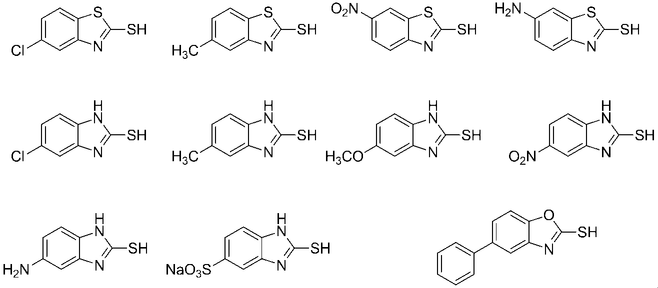

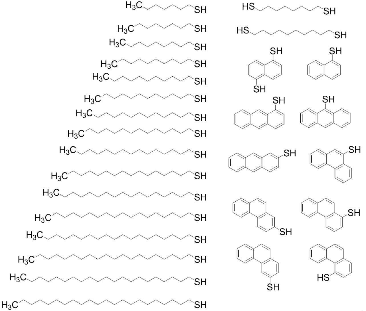
連鎖移動剤の含有量は、画像記録層の全質量に対し、0.01質量%~50質量%が好ましく、0.05質量%~40質量%がより好ましく、0.1質量%~30質量%が更に好ましい。
画像記録層は、インキ着肉性を向上させるために、感脂化剤を更に含有することが好ましい。
感脂化剤は、SP値が18.0未満であることが好ましく、14~18未満であることがより好ましく、15~17であることが更に好ましく、16~16.9であることが特に好ましい。
また、感脂化剤は、分子量(分子量分布があるときは、重量平均分子量)が2,000以上の化合物であってもよく、分子量が2,000未満の化合物であってもよい。
ハンセン(Hansen)溶解度パラメーターは、ヒルデブランド(Hildebrand)によって導入された溶解度パラメーターを、分散項δd、極性項δp、水素結合項δhの3成分に分割し、3次元空間に表したものであるが、本開示においてはSP値をδ(単位:(MPa)1/2)で表し、下記式を用いて算出される値を用いる。
δ(MPa)1/2=(δd2+δp2+δh2)1/2
なお、この分散項δd、極性項δp、及び、水素結合項δhは、ハンセンやその研究後継者らにより多く求められており、Polymer Handbook (fourth edition)、VII-698~711に詳しく掲載されている。
また本開示において、ポリマーのSP値は、ポリマーの分子構造からPolymer Handbook fourth editionに記載のHoy法により計算する。
特に、最外層に無機層状化合物を含有させる場合、これら化合物は、無機層状化合物の表面被覆剤として機能し、無機層状化合物による印刷途中の着肉性低下を抑制することができる。
オニウム塩化合物としては、ホスホニウム化合物、アンモニウム化合物、スルホニウム化合物等が挙げられ、オニウム塩化合物としては、上記観点から、ホスホニウム化合物及びアンモニウム化合物からなる群より選択される少なくとも1つが好ましい。
また、後述する、現像促進剤又は電子受容型重合開始剤におけるオニウム塩化合物はSP値が18を超える化合物であり、感脂化剤には含まれない。
中でも、第四級アンモニウム塩類及びピリジニウム塩類が好ましい。
具体例としては、テトラメチルアンモニウム=ヘキサフルオロホスファート、テトラブチルアンモニウム=ヘキサフルオロホスファート、ドデシルトリメチルアンモニウム=p-トルエンスルホナート、ベンジルトリエチルアンモニウム=ヘキサフルオロホスファート、ベンジルジメチルオクチルアンモニウム=ヘキサフルオロホスファート、ベンジルジメチルドデシルアンモニウム=ヘキサフルオロホスファート、特開2008-284858号公報の段落0021~0037に記載の化合物、特開2009-90645号公報の段落0030~0057に記載の化合物等が挙げられる。
(1)2-(トリメチルアンモニオ)エチルメタクリレート=p-トルエンスルホナート/3,6-ジオキサヘプチルメタクリレート共重合体(モル比10/90、Mw4.5万)
(2)2-(トリメチルアンモニオ)エチルメタクリレート=ヘキサフルオロホスファート/3,6-ジオキサヘプチルメタクリレート共重合体(モル比20/80、Mw6.0万)
(3)2-(エチルジメチルアンモニオ)エチルメタクリレート=p-トルエンスルホナート/ヘキシルメタクリレート共重合体(モル比30/70、Mw4.5万)
(4)2-(トリメチルアンモニオ)エチルメタクリレート=ヘキサフルオロホスファート/2-エチルヘキシルメタクリレート共重合体(モル比20/80、Mw6.0万)
(5)2-(トリメチルアンモニオ)エチルメタクリレート=メチルスルファート/ヘキシルメタクリレート共重合体(モル比40/60、Mw7.0万)
(6)2-(ブチルジメチルアンモニオ)エチルメタクリレート=ヘキサフルオロホスファート/3,6-ジオキサヘプチルメタクリレート共重合体(モル比25/75、Mw6.5万)
(7)2-(ブチルジメチルアンモニオ)エチルアクリレート=ヘキサフルオロホスファート/3,6-ジオキサヘプチルメタクリレート共重合体(モル比20/80、Mw6.5万)
(8)2-(ブチルジメチルアンモニオ)エチルメタクリレート=13-エチル-5,8,11-トリオキサ-1-ヘプタデカンスルホナート/3,6-ジオキサヘプチルメタクリレート共重合体(モル比20/80、Mw7.5万)
本開示において用いられる画像記録層の好ましい態様の一つは、感脂化剤として、2種以上の化合物を含有する態様である。
具体的には、本開示において用いられる画像記録層は、機上現像性及び着肉性を両立させる観点から、感脂化剤としては、ホスホニウム化合物と、含窒素低分子化合物と、アンモニウム基含有ポリマーと、を併用することが好ましく、ホスホニウム化合物と、第四級アンモニウム塩類と、アンモニウム基含有ポリマーと、を併用することがより好ましい。
本開示において用いられる画像記録層は、現像促進剤を更に含むことが好ましい。
現像促進剤は、SP値の極性項の値が6.0~26.0であることが好ましく、6.2~24.0であることがより好ましく、6.3~23.5であることが更に好ましく、6.4~22.0であることが特に好ましい。
δp[cal/cm3]はHansen 溶解度パラメーター双極子間力項、V[cal/cm3]はモル体積、μ[D]は双極子モーメントである。δpとしては、一般的にはHansenとBeerbowerによって簡素化された下記式が用いられている

本開示において、親水性とは、SP値の極性項の値が6.0~26.0であることをいい、親水性高分子化合物とは分子量(分子量分布を有する場合は重量平均分子量)が3,000以上の化合物をいい、親水性低分子化合物とは分子量(分子量分布を有する場合は重量平均分子量)が3,000未満の化合物をいう。
セルロース化合物としては、セルロース、又は、セルロースの少なくとも一部が変性された化合物(変性セルロース化合物)が挙げられ、変性セルロース化合物が好ましい。
変性セルロース化合物としては、セルロースのヒドロキシ基の少なくとも一部が、アルキル基及びヒドロキシアルキル基よりなる群から選ばれた少なくとも一種の基により置換された化合物が好ましく挙げられる。
上記セルロースのヒドロキシ基の少なくとも一部が、アルキル基及びヒドロキシアルキル基よりなる群から選ばれた少なくとも一種の基により置換された化合物の置換度は、0.1~6.0であることが好ましく、1~4であることがより好ましい。
変性セルロース化合物としては、アルキルセルロース化合物又はヒドロキシアルキルセルロース化合物が好ましく、ヒドロキシアルキルセルロース化合物がより好ましい。
アルキルセルロース化合物としては、メチルセルロースが好ましく挙げられる。
ヒドロキシアルキルセルロース化合物としては、ヒドロキシプロピルセルロースが好ましく挙げられる。
ポリオール化合物としては、グリセリン、ペンタエリスリトール、トリス(2-ヒドロキシエチル)イソシアヌレート等が挙げられる。
有機アミン化合物としては、トリエタノールアミン、ジエタノールアミン、モノエタノールアミン等及びその塩が挙げられる。
有機スルホン酸化合物としては、アルキルスルホン酸、トルエンスルホン酸、ベンゼンスルホン酸等及びその塩が挙げられ、アルキル基の炭素数が1~10のアルキルスルホン酸が好ましく挙げられる。
有機スルファミン化合物としては、アルキルスルファミン酸等及びその塩が挙げられる。
有機硫酸化合物としては、アルキル硫酸、アルキルエーテル硫酸等及びその塩が挙げられる。
有機ホスホン酸化合物としては、フェニルホスホン酸等及びその塩、が挙げられる。
有機カルボン酸化合物としては、酒石酸、シュウ酸、クエン酸、リンゴ酸、乳酸、グルコン酸等及びその塩が挙げられる。
ベタイン化合物としては、ホスホベタイン化合物、スルホベタイン化合物、カルボキシベタイン化合物等が挙げられ、トリメチルグリシンが好ましく挙げられる。
環状構造としては、特に限定されないが、ヒドロキシ基の少なくとも一部が置換されていてもよいグルコース環、イソシアヌル環、ヘテロ原子を有していてもよい芳香環、ヘテロ原子を有していてもよい脂肪族環等が挙げられ、グルコース環又はイソシアヌル環が好ましく挙げられる。
グルコース環を有する化合物としては、上述のセルロース化合物が挙げられる。
イソシアヌル環を有する化合物としては、上述のトリス(2-ヒドロキシエチル)イソシアヌレート等が挙げられる。
芳香環を有する化合物としては、上述のトルエンスルホン酸、ベンゼンスルホン酸等が挙げられる。
脂肪族環を有する化合物としては、上述のアルキル硫酸であって、アルキル基が環構造を有する化合物等が挙げられる。
ヒドロキシ基を有し、かつ、環状構造を有する化合物としては、上述のセルロース化合物、及び、上述のトリス(2-ヒドロキシエチル)イソシアヌレートが好ましく挙げられる。
オニウム塩化合物としては、アンモニウム化合物、スルホニウム化合物等が挙げられ、アンモニウム化合物が好ましい。
オニウム塩化合物である現像促進剤としては、トリメチルグリシン等が挙げられる。
また、上記電子受容型重合開始剤におけるオニウム塩化合物はSP値の極性項の値が6.0~26.0ではない化合物であり、現像促進剤には含まれない。
本開示において用いられる画像記録層の好ましい態様の一つは、現像促進剤として、2種以上の化合物を含有する態様である。
具体的には、本開示において用いられる画像記録層は、機上現像性及び着肉性の観点から、現像促進剤として、上記ポリオール化合物及び上記ベタイン化合物、上記ベタイン化合物及び上記有機スルホン酸化合物、又は、上記ポリオール化合物及び上記有機スルホン酸化合物を含むことが好ましい。
画像記録層には、その他の成分として、界面活性剤、重合禁止剤、高級脂肪酸誘導体、可塑剤、無機粒子、無機層状化合物等を含有することができる。具体的には、特開2008-284817号公報の段落0114~段落0159の記載を参照することができる。
本開示に係る平版印刷版原版における画像記録層は、例えば、特開2008-195018号公報の段落0142~段落0143に記載のように、必要な上記各成分を公知の溶剤に分散又は溶解して塗布液を調製し、塗布液を支持体上にバーコーター塗布など公知の方法で塗布し、乾燥することにより形成することができる。塗布、乾燥後における画像記録層の塗布量(固形分)は、用途によって異なるが、0.3g/m2~3.0g/m2が好ましい。この範囲で、良好な感度と画像記録層の良好な皮膜特性が得られる。
溶剤としては、公知の溶剤を用いることができる。具体的には、例えば、水、アセトン、メチルエチルケトン(2-ブタノン)、シクロヘキサン、酢酸エチル、エチレンジクロライド、テトラヒドロフラン、トルエン、エチレングリコールモノメチルエーテル、エチレングリコールモノエチルエーテル、エチレングリコールジメチルエーテル、プロピレングリコールモノメチルエーテル、プロピレングリコールモノエチルエーテル、アセチルアセトン、シクロヘキサノン、ジアセトンアルコール、エチレングリコールモノメーチルエーテルアセテート、エチレングリコールエチルエーテルアセテート、エチレングリコールモノイソプロピルエーテル、エチレングリコールモノブチルエーテルアセテート、1-メトキシ-2-プロパノール、3-メトキシ-1-プロパノール、メトキシメトキシエタノール、ジエチレングリコールモノメチルエーテル、ジエチレングリコールモノエチルエーテル、ジエチレングリコールジメチルエーテル、ジエチレングリコールジエチルエーテル、プロピレングリコールモノメチルエーテルアセテート、プロピレングリコールモノエチルエーテルアセテート、3-メトキシプロピルアセテート、N,N-ジメチルホルムアミド、ジメチルスルホキシド、γ-ブチロラクトン、乳酸メチル、乳酸エチル等が挙げられる。溶剤は、1種単独で使用してもよいし、2種以上を併用してもよい。塗布液中の固形分濃度は1質量%~50質量%であることが好ましい。
塗布、乾燥後における画像記録層の塗布量(固形分)は、用途によって異なるが、良好な感度と画像記録層の良好な皮膜特性を得る観点から、0.3g/m2~3.0g/m2が好ましい。
また、本開示に係る平版印刷版原版における画像記録層の膜厚は、0.1μm~3.0μmであることが好ましく、0.3μm~2.0μmであることがより好ましい。
本開示において、平版印刷版原版における各層の膜厚は、平版印刷版原版の表面に対して垂直な方向に切断した切片を作製し、上記切片の断面を走査型顕微鏡(SEM)により観察することにより確認される。
本開示に係る平版印刷版原版は、支持体を有する。
支持体としては、公知の平版印刷版原版用支持体から適宜選択して用いることができる。
支持体としては、親水性表面を有する支持体(以下、「親水性支持体」ともいう。)が好ましい。
更に、上記マイクロポアが、上記陽極酸化皮膜表面から深さ10nm~1,000nmの位置までのびる大径孔部と、上記大径孔部の底部と連通し、連通位置から深さ20nm~2,000nmの位置までのびる小径孔部とから構成され、上記大径孔部の上記陽極酸化皮膜表面における平均径が、15nm~100nmであり、上記小径孔部の上記連通位置における平均径が、13nm以下であることが好ましい。
アルミニウム支持体12aは、アルミニウム板18とアルミニウムの陽極酸化皮膜20a(以後、単に「陽極酸化皮膜20a」とも称する)とをこの順で積層した積層構造を有する。なお、アルミニウム支持体12a中の陽極酸化皮膜20aが、アルミニウム板18よりも画像記録層側に位置する。つまり、本開示に係る平版印刷版原版は、アルミニウム板上に、陽極酸化皮膜、画像記録層、及び水溶性樹脂層をこの順で少なくとも有することが好ましい。
以下、陽極酸化被膜20aの好ましい態様について説明する。
陽極酸化皮膜20aは、陽極酸化処理によってアルミニウム板18の表面に作製される皮膜であって、この皮膜は、皮膜表面に略垂直であり、かつ、個々が均一に分布した極微細なマイクロポア22aを有する。マイクロポア22aは、画像記録層側の陽極酸化皮膜20a表面(アルミニウム板18側とは反対側の陽極酸化皮膜20a表面)から厚み方向(アルミニウム板18側)に沿ってのびる。
平均径が10nmを超える場合、耐刷性及び画像視認性に優れる。また、平均径が100nm以下である場合、耐刷性に優れる。
マイクロポア22aの平均径は、陽極酸化皮膜20a表面を倍率15万倍の電界放出型走査電子顕微鏡(FE-SEM)でN=4枚観察し、得られた4枚の画像において、400nm×600nmの範囲に存在するマイクロポアの径(直径)を50箇所測定し、平均した値である。
なお、マイクロポア22aの形状が円状でない場合は、円相当径を用いる。「円相当径」とは、開口部の形状を、開口部の投影面積と同じ投影面積をもつ円と想定したときの円の直径である。
例えば、図2に示すように、アルミニウム支持体12bが、アルミニウム板18と、大径孔部24と小径孔部26とから構成されるマイクロポア22bを有する陽極酸化皮膜20bとを含む形態であってもよい。
例えば、陽極酸化皮膜20b中のマイクロポア22bは、陽極酸化皮膜表面から深さ10nm~1000nm(深さD:図2参照)の位置までのびる大径孔部24と、大径孔部24の底部と連通し、連通位置から更に深さ20nm~2,000nmの位置までのびる小径孔部26とから構成される。具体的には、例えば、特開2019-162855号公報の段落0107~0114に記載の態様を使用することができる。
本開示に用いられる支持体の製造方法としては、例えば、以下の工程を順番に実施する製造方法が好ましい。
・粗面化処理工程:アルミニウム板に粗面化処理を施す工程
・陽極酸化処理工程:粗面化処理されたアルミニウム板を陽極酸化する工程
・ポアワイド処理工程:陽極酸化処理工程で得られた陽極酸化皮膜を有するアルミニウム板を、酸水溶液又はアルカリ水溶液に接触させ、陽極酸化皮膜中のマイクロポアの径を拡大させる工程
以下、各工程の手順について詳述する。
粗面化処理工程は、アルミニウム板の表面に、電気化学的粗面化処理を含む粗面化処理を施す工程である。本工程は、後述する陽極酸化処理工程の前に実施されることが好ましいが、アルミニウム板の表面がすでに好ましい表面形状を有していれば、特に実施しなくてもよい。特開2019-162855号公報の段落0086~0101に記載された方法で行うことができる。
陽極酸化処理工程の手順は、上述したマイクロポアが得られれば特に制限されず、公知の方法が挙げられる。
陽極酸化処理工程においては、硫酸、リン酸、及び、シュウ酸等の水溶液を電解浴として用いることができる。例えば、硫酸の濃度は、100g/L~300g/Lが挙げられる。
陽極酸化処理の条件は使用される電解液によって適宜設定されるが、例えば、液温5℃~70℃(好ましくは10℃~60℃)、電流密度0.5A/dm2~60A/dm2(好ましくは1A/dm2~60A/dm2)、電圧1V~100V(好ましくは5V~50V)、電解時間1秒~100秒(好ましくは5秒~60秒)、及び、皮膜量0.1g/m2~5g/m2(好ましくは0.2g/m2~3g/m2)が挙げられる。
ポアワイド処理は、上述した陽極酸化処理工程により形成された陽極酸化皮膜に存在するマイクロポアの径(ポア径)を拡大させる処理(孔径拡大処理)である。
ポアワイド処理は、上述した陽極酸化処理工程により得られたアルミニウム板を、酸水溶液又はアルカリ水溶液に接触させることにより行うことができる。接触させる方法は特に制限されず、例えば、浸せき法及びスプレー法が挙げられる。
本開示に係る平版印刷版原版は、画像記録層と支持体との間に下塗り層(中間層と呼ばれることもある。)を有することが好ましい。下塗り層は、露光部においては支持体と画像記録層との密着を強化し、未露光部においては画像記録層の支持体からのはく離を生じやすくさせるため、耐刷性の低下を抑制しながら現像性を向上させることに寄与する。また、赤外線レーザー露光の場合に、下塗り層が断熱層として機能することにより、露光により発生した熱が支持体に拡散して感度が低下するのを防ぐ効果も有する。
支持体表面に吸着可能な吸着性基としては、フェノール性ヒドロキシ基、カルボキシ基、-PO3H2、-OPO3H2、-CONHSO2-、-SO2NHSO2-、-COCH2COCH3が好ましい。親水性基としては、スルホ基又はその塩、カルボキシ基の塩が好ましい。架橋性基としては、アクリル基、メタクリル基、アクリルアミド基、メタクリルアミド基、アリル基などが好ましい。
ポリマーは、ポリマーの極性置換基と、上記極性置換基と対荷電を有する置換基及びエチレン性不飽和結合を有する化合物との塩形成で導入された架橋性基を有してもよいし、上記以外のモノマー、好ましくは親水性モノマーが更に共重合されていてもよい。
より好ましいものとして、特開2005-125749号及び特開2006-188038号公報に記載の支持体表面に吸着可能な吸着性基、親水性基及び架橋性基を有する高分子ポリマーが挙げられる。
下塗り層に用いられるポリマーの重量平均分子量(Mw)は、5,000以上が好ましく、1万~30万がより好ましい。
本開示に係る平版印刷版原版は、画像記録層の、支持体側とは反対の側の面上に最外層(「保護層」又は「オーバーコート層」と呼ばれることもある。)を有していてもよい。
また、本開示に係る平版印刷版原版は、支持体と、画像記録層と、最外層とをこの順で有することが好ましい。
上記最外層の膜厚は、上記画像記録層の膜厚よりも厚いことが好ましい。
最外層は酸素遮断により画像形成阻害反応を抑制する機能の他、画像記録層における傷の発生防止及び高照度レーザー露光時のアブレーション防止の機能を有していてもよい。
本開示において、水溶性ポリマーとは、70℃、100gの純水に対して1g以上溶解し、かつ、70℃、100gの純水に対して1gのポリマーが溶解した溶液を25℃に冷却しても析出しないポリマーをいう。
最外層において用いられる水溶性ポリマーとしては、例えば、ポリビニルアルコール、変性ポリビニルアルコール、ポリビニルピロリドン、水溶性セルロース誘導体、ポリエチレングリコール、ポリ(メタ)アクリロニトリル等が挙げられる。
変性ポリビニルアルコールとしてはカルボキシ基又はスルホ基を有する酸変性ポリビニルアルコールが好ましく用いられる。具体的には、特開2005-250216号公報及び特開2006-259137号公報に記載の変性ポリビニルアルコールが挙げられる。
上記けん化度は、60%以上が好ましく、70%以上がより好ましく、85%以上が更に好ましい。けん化度の上限は特に限定されず、100%以下であればよい。
上記けん化度は、JIS K 6726:1994に記載の方法に従い測定される。
また、最外層の一態様として、ポリビニルアルコールと、ポリエチレングリコールとを含む態様も好ましく挙げられる。
疎水性ポリマーとは、125℃、100gの純水に対し5g未満で溶解するか、又は、溶解しないポリマーをいう。
疎水性ポリマーとしては、例えば、ポリエチレン、ポリスチレン、ポリ塩化ビニル、ポリ塩化ビニリデン、ポリ(メタ)アクリル酸アルキルエステル(例えば、ポリ(メタ)アクリル酸メチル、ポリ(メタ)アクリル酸エチル、ポリ(メタ)アクリル酸ブチル等)、これらの樹脂の原料モノマーを組み合わせた共重合体等が挙げられる。
また、疎水性ポリマーとしては、ポリビニリデンクロライド樹脂を含むことが好ましい。
更に、疎水性ポリマーとしては、スチレン-アクリル共重合体(スチレンアクリル樹脂ともいう。)を含むことが好ましい。
更にまた、疎水性ポリマーは、機上現像性の観点から、疎水性ポリマー粒子であることが好ましい。
疎水性ポリマーの最外層表面における占有面積率の上限としては、例えば、90面積%が挙げられる。
疎水性ポリマーの最外層表面における占有面積率は、以下のようにして測定することができる。
アルバック・ファイ社製PHI nano TOFII型飛行時間型二次イオン質量分析装置(TOF-SIMS)を用い、最外層表面に加速電圧30kVでBiイオンビーム(一次イオン)を照射し、表面から放出される疎水部(即ち、疎水性ポリマーによる領域)に相当するイオン(二次イオン)のピークを測定することで、疎水部のマッピングを行い、100μm2あたりに占める疎水部の面積を測定し、疎水部の占有面積率を求め、これを「疎水性ポリマーの最外層表面における占有面積率」とする。
例えば、疎水性ポリマーがアクリル樹脂である場合は、C6H13O-のピークにより測定を行う。また、疎水性ポリマーがポリ塩化ビニリデンである場合は、C2H2Cl+のピークにより測定を行う。
上記占有面積率は、疎水性ポリマーの添加量等によって、調整しうる。
最外層に含まれる赤外線吸収剤は、赤外線吸収剤Aであっても、赤外線吸収剤Bであっても、これら以外の赤外線吸収剤Cであってもよいが、経時視認性、及び、保存安定性の観点から、赤外線吸収剤A及び赤外線吸収剤Cよりなる群から選ばれた少なくとも1種であることが好ましく、赤外線吸収剤Cであることがより好ましい。
赤外線吸収剤としては、画像記録層において上述したものが好適に挙げられる。
最外層中の赤外線吸収剤の含有量は、経時視認性、及び、保存安定性の観点から、最外層の全質量に対し、0.10質量%~50質量%が好ましく、0.50質量%~30質量%がより好ましく、1.0質量%~20質量%が更に好ましい。
発色剤としては、画像記録層において上述したものが好適に挙げられる。
最外層中の発色剤の含有量は、発色性の観点から、最外層の全質量に対し、0.10質量%~50質量%が好ましく、0.50質量%~30質量%がより好ましく、1.0質量%~20質量%が更に好ましい。
好ましく用いられる無機層状化合物は雲母化合物である。雲母化合物としては、例えば、式:A(B,C)2-5D4O10(OH,F,O)2〔ただし、Aは、K、Na、Caのいずれか、B及びCは、Fe(II)、Fe(III)、Mn、Al、Mg、Vのいずれかであり、Dは、Si又はAlである。〕で表される天然雲母、合成雲母等の雲母群が挙げられる。
本開示に係る平版印刷版原版における最外層の膜厚は、0.1μm~5.0μmであることが好ましく、0.3μm~4.0μmであることがより好ましい。
本開示に係る平版印刷版原版における最外層の膜厚は、上記画像記録層の膜厚に対し、1.1倍~5.0倍であることが好ましく、1.5倍~3.0倍であることがより好ましい。
その他の層としては、特に制限はなく、公知の層を有することができる。例えば、支持体の画像記録層側とは反対側には、必要に応じてバックコート層が設けられていてもよい。
本開示に係る平版印刷版原版を画像露光して現像処理を行うことで平版印刷版を作製することができる。
本開示に係る平版印刷版の作製方法は、本開示に係る機上現像型平版印刷版原版を、画像様に露光する工程(以下、「露光工程」ともいう。)と、印刷機上で印刷インキ及び湿し水よりなる群から選ばれた少なくとも一方を供給して非画像部の画像記録層を除去する工程(以下、「機上現像工程」ともいう。)と、を含むことが好ましい。
本開示に係る平版印刷方法は、本開示に係る機上現像型平版印刷版原版を画像様に露光する工程(露光工程)と、印刷インキ及び湿し水よりなる群から選ばれた少なくとも一方を供給して印刷機上で非画像部の画像記録層を除去し平版印刷版を作製する工程(機上現像工程)と、得られた平版印刷版により印刷する工程(印刷工程)と、を含むことが好ましい。
更に、本開示に係る平版印刷版の作製方法は、機上現像型平版印刷版原版を赤外線レーザーによって画像様に露光する工程と、印刷機上で印刷インキ及び湿し水よりなる群から選ばれた少なくとも一方を供給して非画像部の画像記録層を除去する工程と、を含み、上記機上現像型平版印刷版原版が、支持体、及び、上記支持体上に画像記録層を有し、上記画像記録層が、開始剤、赤外線吸収剤、及び、発色体前駆体を含み、上記画像記録層が、下記式Lを満たす平版印刷版の作製方法であることが好ましい。
2.0≦L1-L0 式L
式L中、L1は、上記画像記録層の視認性を表し、L0は、上記発色体前駆体を除いた以外は上記画像記録層と同一である層の視認性を表す。
また、本開示に係る平版印刷方法についても、これらの態様にそれぞれ、上記印刷工程を更に含む態様が好ましく挙げられる。
以下、平版印刷版の作製方法における露光工程及び機上現像工程について説明するが、本開示に係る平版印刷版の作製方法における露光工程と、本開示に係る平版印刷方法における露光工程とは同様の工程であり、本開示に係る平版印刷版の作製方法における機上現像工程と、本開示に係る平版印刷方法における機上現像工程とは同様の工程である。
本開示に係る平版印刷版の作製方法は、本開示に係る平版印刷版原版を画像様に露光し、露光部と未露光部とを形成する露光工程を含むことが好ましい。本開示に係る平版印刷版原版は、線画像、網点画像等を有する透明原画を通してレーザー露光するかデジタルデータによるレーザー光走査等で画像様に露光されることが好ましい。
光源の波長は750nm~1,400nmが好ましく用いられる。波長750nm~1,400nmの光源としては、赤外線を放射する固体レーザー及び半導体レーザーが好適である。赤外線レーザーに関しては、出力は100mW以上であることが好ましく、1画素当たりの露光時間は20マイクロ秒以内であるのが好ましく、また照射エネルギー量は10mJ/cm2~300mJ/cm2であるのが好ましい。また、露光時間を短縮するためマルチビームレーザーデバイスを用いることが好ましい。露光機構は、内面ドラム方式、外面ドラム方式、及びフラットベッド方式等のいずれでもよい。
画像露光は、プレートセッターなどを用いて常法により行うことができる。機上現像の場合には、平版印刷版原版を印刷機に装着した後、印刷機上で画像露光を行ってもよい。
本開示に係る平版印刷版の作製方法は、印刷機上で印刷インキ及び湿し水よりなる群から選ばれた少なくとも一方を供給して非画像部の画像記録層を除去する機上現像工程を含むことが好ましい。
以下に、機上現像方式について説明する。
機上現像方式においては、画像露光された平版印刷版原版は、印刷機上で油性インキと水性成分とを供給し、非画像部の画像記録層が除去されて平版印刷版が作製されることが好ましい。
すなわち、平版印刷版原版を画像露光後、何らの現像処理を施すことなくそのまま印刷機に装着するか、あるいは、平版印刷版原版を印刷機に装着した後、印刷機上で画像露光し、ついで、油性インキと水性成分とを供給して印刷すると、印刷途上の初期の段階で、非画像部においては、供給された油性インキ及び水性成分のいずれか又は両方によって、未硬化の画像記録層が溶解又は分散して除去され、その部分に親水性の表面が露出する。一方、露光部においては、露光により硬化した画像記録層が、親油性表面を有する油性インキ受容部を形成する。最初に版面に供給されるのは、油性インキでもよく、水性成分でもよいが、水性成分が除去された画像記録層の成分によって汚染されることを防止する点で、最初に油性インキを供給することが好ましい。このようにして、平版印刷版原版は印刷機上で機上現像され、そのまま多数枚の印刷に用いられる。油性インキ及び水性成分としては、通常の平版印刷用の印刷インキ及び湿し水が好適に用いられる。
本開示に係る平版印刷方法は、平版印刷版に印刷インキを供給して記録媒体を印刷する印刷工程を含む。
印刷インキとしては、特に制限はなく、所望に応じ、種々の公知のインキを用いることができる。また、印刷インキとしては、油性インキ又は紫外線硬化型インキ(UVインキ)が好ましく挙げられる。
また、上記印刷工程においては、必要に応じ、湿し水を供給してもよい。
また、上記印刷工程は、印刷機を停止することなく、上記機上現像工程に連続して行われてもよい。
記録媒体としては、特に制限はなく、所望に応じ、公知の記録媒体を用いることができる。
<支持体の準備>
(a)アルカリエッチング処理
アルミニウム板に、カセイソーダ濃度26質量%及びアルミニウムイオン濃度6.5質量%のカセイソーダ水溶液を、温度70℃でスプレーにより吹き付けてエッチング処理を行った。その後、スプレーによる水洗を行った。後に電気化学的粗面化処理を施す面のアルミニウム溶解量は、5g/m2であった。
次に、酸性水溶液を用いてデスマット処理を行った。デスマット処理に用いる酸性水溶液は、硫酸150g/Lの水溶液を用いた。その液温は30℃であった。酸性水溶液をアルミニウム板にスプレーにて吹き付けて、3秒間デスマット処理を行った。その後、水洗処理を行った。
次に、塩酸濃度14g/L、アルミニウムイオン濃度13g/L、及び、硫酸濃度3g/Lの電解液を用い、交流電流を用いて電気化学的粗面化処理を行った。電解液の液温は30℃であった。アルミニウムイオン濃度は塩化アルミニウムを添加して調整した。
交流電流の波形は正と負の波形が対称な正弦波であり、周波数は50Hz、交流電流1周期におけるアノード反応時間とカソード反応時間は1:1、電流密度は交流電流波形のピーク電流値で75A/dm2であった。また、電気量はアルミニウム板がアノード反応に預かる電気量の総和で450C/dm2であり、電解処理は112.5C/dm2ずつ4秒間の通電間隔を開けて4回に分けて行った。アルミニウム板の対極にはカーボン電極を用いた。その後、水洗処理を行った。
電気化学的粗面化処理後のアルミニウム板に、カセイソーダ濃度5質量%及びアルミニウムイオン濃度0.5質量%のカセイソーダ水溶液を、温度45℃でスプレーにより吹き付けてエッチング処理を行った。電気化学的粗面化処理が施された面のアルミニウムの溶解量は0.2g/m2であった。その後、水洗処理を行った。
次に、酸性水溶液を用いてデスマット処理を行った。具体的には、酸性水溶液をアルミニウム板にスプレーにて吹き付けて、3秒間デスマット処理を行った。デスマット処理に用いる酸性水溶液は、硫酸濃度170g/L及びアルミニウムイオン濃度5g/Lの水溶液を用いた。その液温は30℃であった。
図3に示す構造の直流電解による陽極酸化処理装置610を用いて、第1段階の陽極酸化処理(第1陽極酸化処理ともいう)を行った。具体的には、下記表1に示す「第1陽極酸化処理」欄の条件にて第1陽極酸化処理を行い、所定の皮膜量の陽極酸化皮膜を形成した。
以下、図3に示す陽極酸化処理装置610について説明する。
図3に示す陽極酸化処理装置610において、アルミニウム板616は、図3中矢印で示すように搬送される。電解液618が貯溜された給電槽612にてアルミニウム板616は給電電極620によって(+)に荷電される。そして、アルミニウム板616は、給電槽612においてローラ622によって上方に搬送され、ニップローラ624によって下方に方向変換された後、電解液626が貯溜された電解処理槽614に向けて搬送され、ローラ628によって水平方向に方向転換される。次いで、アルミニウム板616は、電解電極630によって(-)に荷電されることにより、その表面に陽極酸化皮膜が形成され、電解処理槽614を出たアルミニウム板616は後工程に搬送される。陽極酸化装置610において、ローラ622、ニップローラ624、及びローラ628によって方向転換手段が構成され、アルミニウム板616は、給電槽612と電解処理槽614との槽間部において、上記ローラ622、624及び628により、山型及び逆U字型に搬送される。給電電極620と電解電極630とは、直流電源634に接続されている。
上記陽極酸化処理したアルミニウム板を、温度40℃、カセイソーダ濃度5質量%、アルミニウムイオン濃度0.5質量%のカセイソーダ水溶液に下記表1に示す条件で浸漬し、ポアワイド処理を行った。その後、スプレーによる水洗を行った。
図3に示す構造の直流電解による陽極酸化処理装置610を用いて、第2段階の陽極酸化処理(第2陽極酸化処理ともいう)を行った。具体的には、下記表1に示す「第2陽極酸化処理」欄の条件にて第2陽極酸化処理を行い、所定の皮膜量の陽極酸化皮膜を形成した。
得られた支持体の、マイクロポアの陽極酸化皮膜表面のL*a*b*表色系における明度L*、マイクロポアにおける大径孔部の酸化皮膜表面における平均径及び深さ、マイクロポアにおける小径孔部の連通位置における平均径(nm)及び深さ、大径孔部及び小径孔部の深さ(nm)、マイクロポア密度、並びに、小径孔部の底部からアルミニウム板表面までの陽極酸化皮膜の厚み(皮膜厚ともいう)を、表2にまとめて示す。
なお、表1中、第1陽極酸化処理欄の皮膜量(AD)量と第2陽極酸化処理欄の皮膜量(AD)とは、各処理で得られた皮膜量を表す。なお、使用される電解液は、表1中の成分を含む水溶液である。


得られた支持体上に、下記組成の下塗り層塗布液を乾燥塗布量が0.1g/m2になるよう塗布して、下塗り層を形成した。
・下塗り層用化合物(下記U-1、11%水溶液):0.10502部
・グルコン酸ナトリウム:0.0700部
・界面活性剤(エマレックス(登録商標) 710、日本エマルジョン(株)):0.00159部
・防腐剤(バイオホープL、ケイ・アイ化成(株)):0.00149部
・水:3.29000部
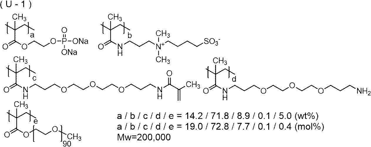
下塗り層上に、下記画像記録層塗布液をバー塗布し、120℃で40秒間オーブン乾燥して、乾燥塗布量1.0g/m2の画像記録層を形成した。
下記に示す各成分を、1-メトキシ-2-プロパノール(MFG):メチルエチルケトン(MEK):メタノール=4:4:1(質量比)の混合溶媒で溶解又は分散し、固形分が6質量%になるように調製し、画像記録層塗布液を作製した。
・表3に記載の赤外線吸収剤1種又は2種:乾燥後に含有量が表3に記載の量となる量
・重合開始剤IA-1(下記化合物、LUMO=-3.02eV):100質量部
・電子供与型重合開始剤TPB(テトラフェニルホウ酸ナトリウム、HOMO=-5.90eV):20質量部
・重合性化合物M-1(ウレタン(メタ)アクリレートオリゴマー、U-10HA(官能基数:10)、新中村化学工業(株)製):500質量部
・重合性化合物M-2(2官能メタクリレート化合物、AZ Electronics社製FST 510(1モル当量の2,2,4-トリメチルヘキサメチレンジイソシアネートと2モル当量のヒドロキシエチルメタクリレートの反応生成物あって、下記構造の化合物のメチルエチルケトン82質量%溶液)):250質量部
・重合性化合物M-3(エトキシ化ビスフェノールAジメタクリレート、下記構造の化合物、新中村化学工業(株)製BPE-80N):250質量部
・表3に記載の発色剤(実施例1~20並びに比較例1及び2ではS-1、下記化合物):25質量部
・アニオン界面活性剤A-1(下記構造の化合物):25質量部
・フッ素系界面活性剤W-1(下記構造の化合物、重量平均分子量:13,000):5質量部
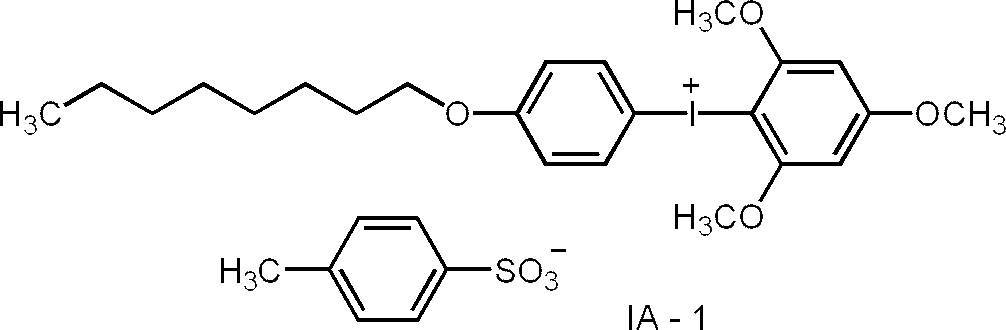


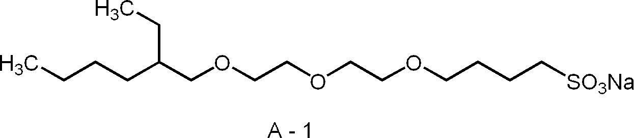

実施例15~20及び23~28では、画像記録層上に、下記最外層塗布液をバー塗布し、120℃で60秒間オーブン乾燥して、乾燥塗布量が0.41g/m2の最外層を形成した。
以上の工程を経て、各実施例比較例の平版印刷版原版を得た。
下記に示す各成分を、イオン交換水で溶解又は分散し、固形分が20質量%になるように調製し、最外層塗布液を作製した。
・表3に記載の赤外線吸収剤:乾燥後に含有量が表3に記載の量となる量
・水溶性ポリマー(ポリビニルアルコール、(株)クラレ製Mowiol 4-88):250質量部
・疎水性ポリマー(ポリ塩化ビニリデン水性ディスパージョン、Solvin社製Diofan(登録商標) A50):250質量部
・界面活性剤(ノニオン界面活性剤、BASF社製Lutensol(登録商標) A8):10質量部
(1)視認性の評価
得られた平版印刷版原版を、水冷式40W赤外線半導体レーザー搭載のCreo社製Trendsetter3244VXにより、出力11.5W、外面ドラム回転数220rpm、解像度2,400dpiの条件で露光した。露光は25℃、50%RHの環境下で行った。
露光直後の平版印刷版原版(初期の平版印刷版原版ともいう)と、露光後の平版印刷版原版を25℃、70%RHの条件で24時間保管した後の平版印刷版原版(経時後の平版印刷版原版ともいう)と、のそれぞれについて発色を測定した。測定は、コニカミノルタ(株)製分光測色計CM2600dとオペレーションソフトCM-S100Wとを用い、SCE(正反射光除去)方式で行った。視認性(視認性)は、L*a*b*表色系のL*値(明度)を用い、露光部のL*値と未露光部のL*値との差ΔLにより評価した。ΔLの値が大きい程、視認性が優れるといえる。結果を表3に記載した。
-評価基準-
3:ΔLが5.0以上である
2:ΔLが3.0以上5.0未満である
1:ΔLが3.0未満である
上記のようにして作製した平版印刷版原版を、赤外線半導体レーザー搭載のKodak社製Magnus800 Quantumにて、出力27W、外面ドラム回転数450rpm、解像度2,400dpi(dot per inch、1inchは2.54cm)の条件で露光(照射エネルギー110mJ/cm2相当)した。露光画像にはベタ画像、及び、AMスクリーン(Amplitude Modulation Screen)50%網点のチャートを含むようにした。
得られた露光済み原版を現像処理することなく、菊判サイズのハイデルベルグ社製印刷機SX-74のシリンダーに取り付けた。本印刷機には、不織布フィルターと温度制御装置を内蔵する容量100Lの湿し水循環タンクを接続した。湿し水S-Z1(富士フイルム(株)製)2.0%の湿し水80Lを循環装置内に仕込み、印刷インキとしてT&K UV OFS K-HS墨GE-M((株)T&K TOKA製)を用い、標準の自動印刷スタート方法で湿し水とインキを供給した後、毎時10,000枚の印刷速度で特菱アート紙(連量:76.5kg、三菱製紙(株)製)に200枚印刷を行った。
上記機上現像において、非画像部にインキが転写しない状態になるまでに要した印刷用紙の枚数(以降、機上現像枚数ともいう)を求めた。機上現像枚数が少ないほど、機上現像性が良好であるといえる。
上記の機上現像枚数の測定を、調液及び塗布を2日間で実施し、版を作製してから60℃60%RHの条件で3日間保管した後の平版印刷版原版(経時後の平版印刷版原版ともいう)と、に対して行った。
-評価基準(4段階評価)-
4:機上現像枚数が20枚以下
3:機上現像枚数が20枚超30枚以下
2:機上現像枚数が30枚超50枚以下
1:機上現像回数が50枚超
上記のようにして作製した平版印刷版原版を、赤外線半導体レーザー搭載のKodak社製Magnus800 Quantumにて、出力27W、外面ドラム回転数450rpm、解像度2,400dpiの条件で露光(照射エネルギー110mJ/cm2相当)した。露光画像にはベタ画像、及び、AMスクリーン10%網点のチャートを含むようにした。
得られた露光済み原版を現像処理することなく、菊判サイズのハイデルベルグ社製印刷機SX-74のシリンダーに取り付けた。本印刷機には、不織布フィルターと温度制御装置を内蔵する容量100Lの湿し水循環タンクを接続した。湿し水S-Z1(富士フイルム(株)製)2.0%の湿し水80Lを循環装置内に仕込み、印刷インキとしてT&K UV OFS K-HS墨GE-M((株)T&K TOKA製)を用い、標準の自動印刷スタート方法で湿し水とインキを供給した後、毎時10,000枚の印刷速度で特菱アート(連量:76.5kg、三菱製紙(株)製)紙に500枚印刷を行った。
続けて、更に印刷を行った。印刷枚数を増やしていくと徐々に画像部が磨耗するため印刷物上のインキ濃度が低下した。印刷物におけるAMスクリーン10%網点の網点面積率をグレタグ濃度計(GretagMacbeth社製)で計測した値が、印刷500枚目の計測値よりも3%低下したときの印刷部数を刷了枚数として耐刷性を評価した。
印刷枚数が5万枚の場合を100とする相対耐刷性により以下の基準で評価した。数値が大きいほど、耐刷性が良好である。評価結果は表3に記載した。
相対耐刷性=(対象平版印刷版原版の印刷枚数)/50,000×100
-評価基準-
3:相対耐刷性の値が90を超える
2:相対耐刷性の値が80を超え90以下である
1:相対耐刷性の値が80以下である
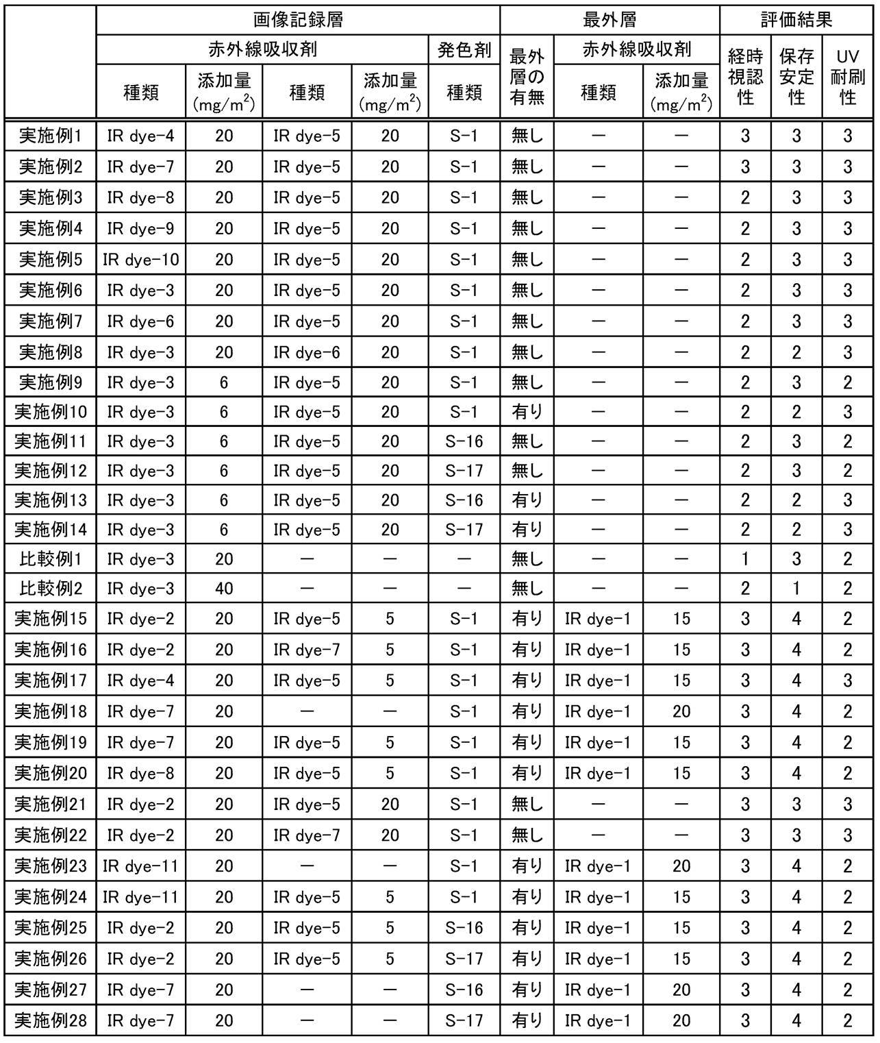
IR dye-1:分解発色型赤外線吸収剤、下記構造の化合物、λmax=770nm
IR dye-2:分解発色型赤外線吸収剤、下記構造の化合物、λmax=830nm
IR dye-3:非分解型赤外線吸収剤、下記構造の化合物、λmax=794nm
IR dye-4:分解発色型赤外線吸収剤、下記構造の化合物、λmax=800nm
IR dye-5:非分解型赤外線吸収剤、下記構造の化合物、λmax=844nm
IR dye-6:非分解型赤外線吸収剤、下記構造の化合物、λmax=812nm
IR dye-7:分解発色型赤外線吸収剤、下記構造の化合物、λmax=830nm
IR dye-8:非分解型赤外線吸収剤、下記構造の化合物、λmax=819nm
IR dye-9:非分解型赤外線吸収剤、下記構造の化合物、λmax=805nm
IR dye-10:非分解型赤外線吸収剤、下記構造の化合物、λmax=803nm
IR dye-11:非分解型赤外線吸収剤、下記構造の化合物、λmax=791nm

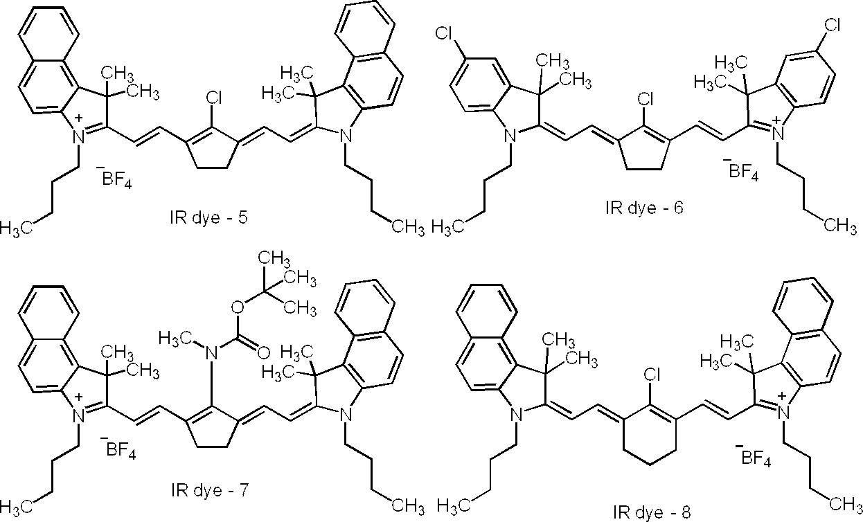
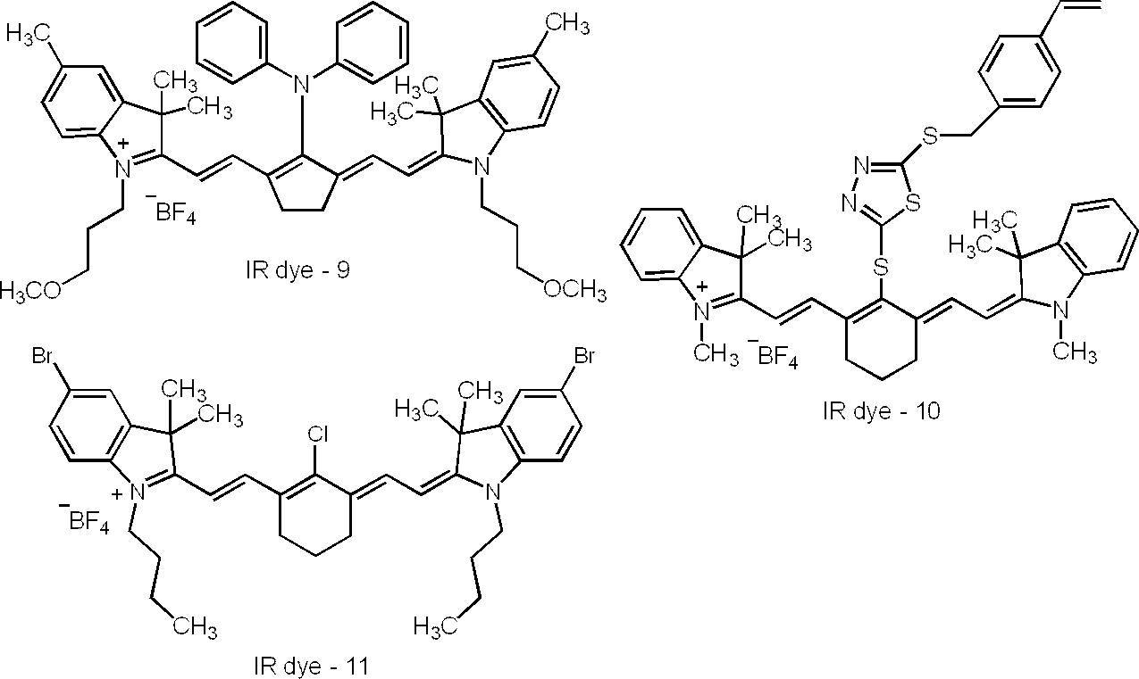
S-17:上述したS-17
また、実施例に係る平版印刷版原版は、UV耐刷性にも優れた平版印刷版が得られることが分かる。
下記成分を混合し、下塗り層塗布液1を調製した。
・下塗り層用化合物(上記U-1、11%水溶液):0.0788部
・ヒドロキシエチルジイミノ二酢酸:0.0280部
・エチレンジアミン四酢酸ナトリウム・4水和物:0.0499部
・界面活性剤(エマレックス(登録商標) 710、日本エマルジョン(株)):0.0016部
・防腐剤(バイオホープL、ケイ・アイ化成(株)):0.0015部
・水:2.8701部
下記成分を混合し、下塗り層塗布液2を調製した。
・下塗り層用化合物(上記U-1、11%水溶液):0.0788部
・グルコン酸ナトリウム:0.0700部
・界面活性剤(エマレックス(登録商標) 710、日本エマルジョン(株)):0.0016部
・防腐剤(バイオホープL、ケイ・アイ化成(株)):0.0015部
・水:2.8780部
下記成分を混合し、画像記録層塗布液1を調製した。
・表4に記載の赤外線吸収剤2種:乾燥後に含有量が表4に記載の量となる量
・発色剤(S-22):0.0120部
・発色剤(S-16):0.0300部
・電子受容型重合開始剤(IA-1):0.0981部
・電子供与型重合開始剤(TPB):0.0270部
・重合性化合物(下記M-4):0.3536部
・トリクレシルホスフェート:0.0450部
・アニオン界面活性剤(A-1):0.0162部
・フッ素系界面活性剤(W-1):0.0042部
・2-ブタノン:5.3155部
・1-メトキシ-2-プロパノール:2.8825部
・メタノール:2.3391部
・ミクロゲル液1:2.8779部

タケネートD-160N(ポリイソシアネート トリメチロールプロパンアダクト体、三井化学(株)製、4.7部)、アロニックスM-403(東亞合成(株)製、タケネートD-160NのNCO価とアロニックスM-403の水酸基価が1:1となる量)、t-ブチルベンゾキノン(0.02部)、及びメチルエチルケトン(11.5部)の混合溶液を65℃に加熱した。反応溶液に、ネオスタンU-600(ビスマス系重縮合触媒、日東化成(株)製、0.11部)を加え、65℃で4時間加熱した。反応溶液を室温(25℃)まで冷却し、メチルエチルケトンを加えることで、固形分が50質量%のウレタンアクリレート(M-4)溶液を合成した。リサイクル型GPC(機器:LC908-C60、カラム:JAIGEL-1H-40及び2H-40(日本分析工業(株)製))を用いて、テトラヒドロフラン(THF)の溶離液にて、ウレタンアクリレート溶液の分子量分画を実施した。重量平均分子量は20,000であった。
-油相成分の調製-
多官能イソシアネート化合物(PM-200:万華化学社製):6.66gと、三井化学(株)製の「タケネート(登録商標)D-116N(トリメチロールプロパン(TMP)とm-キシリレンジイソシアネート(XDI)とポリエチレングリコールモノメチルエーテル(EO90)との付加物(下記構造)」の50質量%酢酸エチル溶液:5.46gと、ジペンタエリスリトールペンタアクリレート(SR-399、サートマー社製)の65質量%酢酸エチル溶液:11.24gと、酢酸エチル:14.47gと、竹本油脂(株)製のパイオニン(登録商標)A-41-C:0.45gを混合し、室温(25℃)で15分撹拌して油相成分を得た。

水相成分として、蒸留水47.2gを準備した。
油相成分に水相成分を添加して混合し、得られた混合物を、ホモジナイザーを用いて12,000rpmで16分間乳化させて乳化物を得た。
得られた乳化物に蒸留水16.8gを添加し、得られた液体を室温で10分撹拌した。
次いで、撹拌後の液体を45℃に加熱し、液温を45℃に保持した状態で4時間撹拌することにより、上記液体から酢酸エチルを留去した。次いで、1,8-ジアザビシクロ[5.4.0]ウンデカ-7-エン-オクチル酸塩(U-CAT SA102、サンアプロ(株)製)の10質量%水溶液5.12gを加え、室温で30分撹拌し、45℃で24時間静置した。蒸留水で、固形分濃度を20質量%になるように調整し、ミクロゲル1の水分散液が得られた。ミクロゲル1の体積平均粒径はレーザー回折/散乱式粒子径分布測定装置LA-920((株)堀場製作所製)により測定したところ、165nmであった。
下記成分を混合し、画像記録層塗布液2を調製した。
・表4に記載の赤外線吸収剤2種:乾燥後に含有量が表4に記載の量となる量
・発色剤(S-22(上述したS-22)):0.0120部
・発色剤(S-16(上述したS-16)):0.0300部
・電子受容型重合開始剤(IA-1):0.0981部
・電子供与型重合開始剤(TPB):0.0270部
・重合性化合物(M-4):0.3536部
・トリクレシルホスフェート:0.0125部
・アニオン界面活性剤(A-1):0.0162部
・パイオニンA-41-C(竹本油脂(株)製、70%メタノール溶液):0.0081部
・フッ素系界面活性剤(W-1):0.0042部
・2-ブタノン:5.3155部
・1-メトキシ-2-プロパノール:2.8825部
・メタノール:2.3391部
・ミクロゲル液1:2.8779部
下記成分を混合し、最外層塗布液1を調製した。
・水:1.0161部
・メトローズSM04(メチルセルロース、信越化学工業(株)製、メトキシ置換度=1.8):0.0600部
・FS-102(スチレン-アクリル樹脂、日本ペイント・インダストリアルコーティングス(株)製、Tg=103℃、17%水分散液):0.1177部
・ラピゾールA-80(アニオン界面活性剤、日油(株)製、80%水溶液):0.0063部
下塗り層塗布液の代わりに下塗り層塗布液1を使用し、
画像記録層塗布液の代わりに画像記録層塗布液1を使用し、
最外層塗布液の代わりに最外層塗布液1を使用した以外は、実施例15と同様にして、平版印刷版原版を作製し、評価を行った。評価結果を表4に示す。
下塗り層塗布液の代わりに下塗り層塗布液2を使用し、
画像記録層塗布液の代わりに画像記録層塗布液1を使用し、
最外層塗布液の代わりに最外層塗布液1を使用した以外は、実施例15と同様にして、平版印刷版原版を作製し、評価を行った。評価結果を表4に示す。
下塗り層塗布液の代わりに下塗り層塗布液1を使用し、
画像記録層塗布液の代わりに画像記録層塗布液2を使用し、
最外層塗布液の代わりに最外層塗布液1を使用した以外は、実施例15と同様にして、平版印刷版原版を作製し、評価を行った。評価結果を表4に示す。
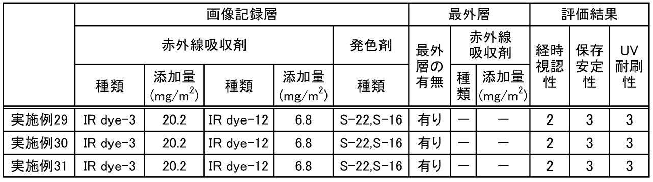
また、実施例に係る平版印刷版原版は、UV耐刷性にも優れた平版印刷版が得られることが分かる。
下塗り層塗布液の代わりに下塗り層塗布液1を使用し、
画像記録層塗布液の代わりに画像記録層塗布液1を使用し、加えて、発色剤の種類をS-23(上述したS-23)に変更し、
更に、最外層塗布液の代わりに最外層塗布液1を使用した以外は、
実施例15と同様にして、平版印刷版原版を作製し、評価を行った。評価結果を表5に示す。
下塗り層塗布液の代わりに下塗り層塗布液1を使用し、
画像記録層塗布液の代わりに画像記録層塗布液1を使用し、加えて、発色剤の種類をS-23に変更し、
更に、最外層塗布を実施していない以外は、
実施例15と同様にして、平版印刷版原版を作製し、評価を行った。評価結果を表5に示す。
下塗り層塗布液の代わりに下塗り層塗布液1を使用し、
画像記録層塗布液の代わりに画像記録層塗布液1を使用し、加えて、発色剤の種類をS-23に変更した以外は、
実施例15と同様にして、平版印刷版原版を作製し、評価を行った。評価結果を表5に示す。
下塗り層塗布液の代わりに下塗り層塗布液1を使用し、
画像記録層塗布液の代わりに画像記録層塗布液1を使用、加えて、重合開始剤の種類を下記IA-6に変更し、更に、発色剤の種類をS-23に変更した以外は、
実施例15と同様にして、平版印刷版原版を作製し、評価を行った。評価結果を表5に示す。
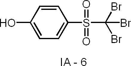
下塗り層塗布液の代わりに下塗り層塗布液1を使用し、
画像記録層塗布液の代わりに画像記録層塗布液1を使用、加えて、重合開始剤の種類を上記IA-6に変更し、更に、発色剤の種類をS-23に変更した以外は、
実施例15と同様にして、平版印刷版原版を作製し、評価を行った。評価結果を表5に示す。
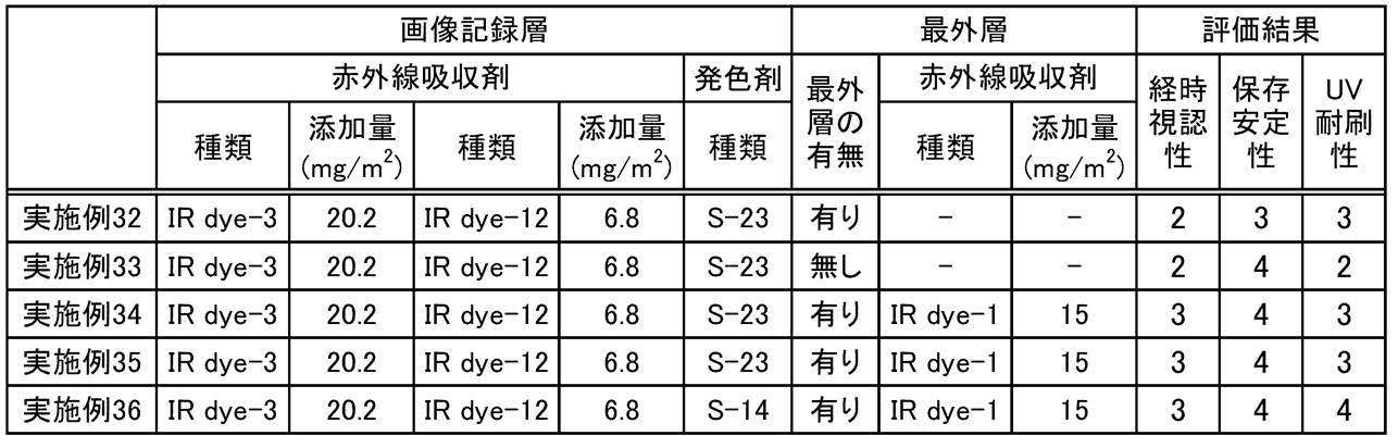
また、実施例に係る平版印刷版原版は、UV耐刷性にも優れた平版印刷版が得られることが分かる。
下記成分を混合し、画像記録層塗布液1を調製した。
・表6に記載の赤外線吸収剤2種:乾燥後に含有量が表6に記載の量となる量
・発色剤(S-22(上述したS-22)):0.0600部
・発色剤(S-16(上述したS-16)):0.0300部
・電子受容型重合開始剤(IA-1):0.0981部
・電子供与型重合開始剤(TPB):0.0270部
・重合性化合物(下記M-4):0.3536部
・トリクレシルホスフェート:0.0450部
・アニオン界面活性剤(A-1):0.0162部
・フッ素系界面活性剤(W-1):0.0042部
・2-ブタノン:5.3155部
・1-メトキシ-2-プロパノール:2.8825部
・メタノール:2.3391部
・ミクロゲル液1:2.8779部
下塗り層塗布液の代わりに下塗り層塗布液1を使用し、
画像記録層塗布液の代わりに画像記録層塗布液3を使用した以外は、
実施例15と同様にして、平版印刷版原版を作製し、評価を行った。評価結果を表6に示す。
下塗り層塗布液の代わりに下塗り層塗布液1を使用し、
画像記録層塗布液の代わりに画像記録層塗布液3を使用し、
更に、最外層塗布液に赤外線吸収剤を添加しなかった以外は、
実施例15と同様にして、平版印刷版原版を作製し、評価を行った。評価結果を表6に示す。
下塗り層塗布液の代わりに下塗り層塗布液1を使用し、
画像記録層塗布液の代わりに画像記録層塗布液3を使用し、
更に、最外層塗布を実施していない以外は、
実施例15と同様にして、平版印刷版原版を作製し、評価を行った。評価結果を表6に示す。
下塗り層塗布液の代わりに下塗り層塗布液1を使用し、
画像記録層塗布液の代わりに画像記録層塗布液3を使用した以外は、
実施例15と同様にして、平版印刷版原版を作製し、評価を行った。評価結果を表6に示す。
下塗り層塗布液の代わりに下塗り層塗布液1を使用し、
画像記録層塗布液の代わりに画像記録層塗布液3を使用し、加えて、発色剤S-16をS-23に変更した以外は、実施例15と同様にして、平版印刷版原版を作製し、評価を行った。評価結果を表6に示す。
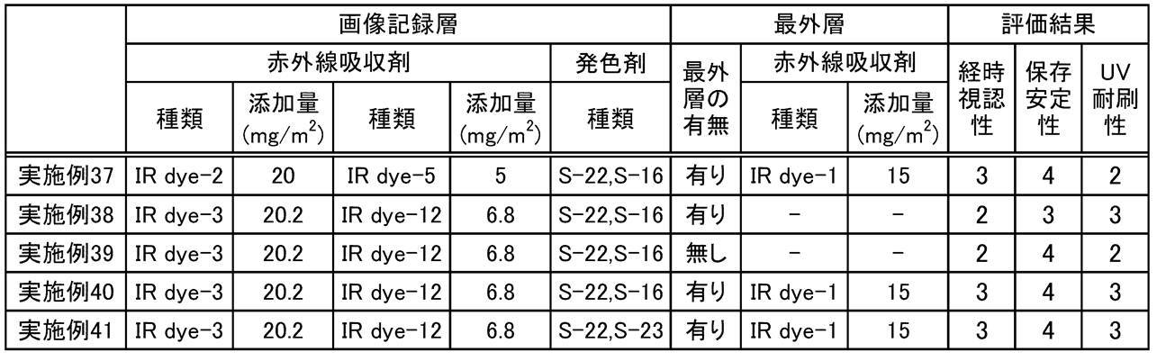
また、実施例に係る平版印刷版原版は、UV耐刷性にも優れた平版印刷版が得られることが分かる。
本明細書に記載された全ての文献、特許出願、及び、技術規格は、個々の文献、特許出願、及び、技術規格が参照により取り込まれることが具体的かつ個々に記された場合と同程度に、本明細書中に参照により取り込まれる。
Claims (39)
- 波長760nm~900nmの範囲において、極大吸収波長を2つ以上有し、
エネルギー密度110mJ/cm2にて波長830nmの赤外線による露光を行った場合の、前記露光を行った部分における前記露光前と前記露光後25℃70%RHの条件にて24時間保管後との明度変化ΔLが、3.0以上である
機上現像型平版印刷版原版。 - 赤外線吸収剤A、及び、赤外線吸収剤Bを含み、
前記赤外線吸収剤Aの最大吸収波長と前記赤外線吸収剤Bの最大吸収波長とが異なり、
エネルギー密度110mJ/cm2にて波長830nmの赤外線による露光を行った場合の、前記露光を行った部分における前記露光前と前記露光後25℃70%RHの条件にて24時間保管後との明度変化ΔLが、3.0以上である
機上現像型平版印刷版原版。 - 支持体上に画像記録層を有し、
前記画像記録層が、前記赤外線吸収剤A、及び、前記赤外線吸収剤Bを含む請求項2に記載の機上現像型平版印刷版原版。 - 支持体と、画像記録層と、最外層と、をこの順で有し、
前記画像記録層が、赤外線吸収剤Aを含み、
前記最外層が、赤外線吸収剤Bを含む請求項2に記載の機上現像型平版印刷版原版。 - 前記赤外線吸収剤Aの最大吸収波長が、830nm超である請求項2~請求項4のいずれか1項に記載の機上現像型平版印刷版原版。
- 前記赤外線吸収剤Bの最大吸収波長が、830nm以下である請求項2~請求項5のいずれか1項に記載の機上現像型平版印刷版原版。
- 前記赤外線吸収剤Aの最大吸収波長と前記赤外線吸収剤Bの最大吸収波長の差が、5nm~50nmである請求項2~請求項6のいずれか1項に記載の機上現像型平版印刷版原版。
- 前記赤外線吸収剤Bが、赤外線露光に起因して分解する分解型赤外線吸収剤である請求項2~請求項7のいずれか1項に記載の機上現像型平版印刷版原版。
- 前記分解型赤外線吸収剤が、下記式1-1で表される化合物である請求項8に記載の機上現像型平版印刷版原版。

式1-1中、R1は下記式2-1~式4-1のいずれかで表される基を表し、R11~R18はそれぞれ独立に、水素原子、ハロゲン原子、-Ra、-ORb、-SRc、又は-NRdReを表し、Ra~Reはそれぞれ独立に、炭化水素基を表し、A1、A2及び複数のR11~R18が連結して単環又は多環を形成してもよく、A1及びA2はそれぞれ独立に、酸素原子、硫黄原子、又は、窒素原子を表し、n11及びn12はそれぞれ独立に、0~5の整数を表し、ただし、n11及びn12の合計は2以上であり、n13及びn14はそれぞれ独立に、0又は1を表し、Lは酸素原子、硫黄原子、又は、-N(R10)-を表し、R10は、水素原子、アルキル基又はアリール基を表し、Zaは電荷を中和する対イオンを表す。
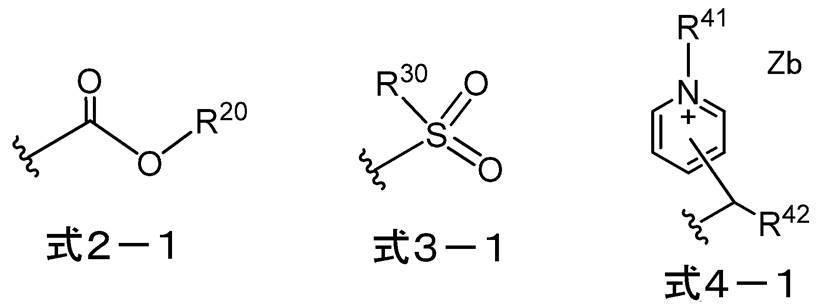
式2-1~式4-1中、R20、R30、R41及びR42はそれぞれ独立に、アルキル基又はアリール基を表し、Zbは電荷を中和する対イオンを表し、波線は、前記式1-1中のLで表される基との結合部位を表す。 - 前記分解型赤外線吸収剤が、下記式1-2で表される化合物である請求項9に記載の機上現像型平版印刷版原版。
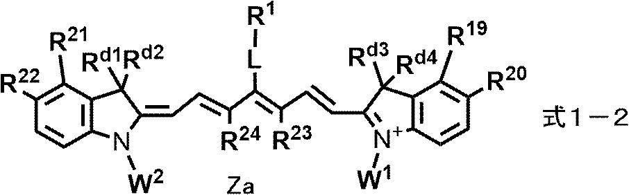
式1-2中、R1は前記式2-1~式4-1のいずれかで表される基を表し、R19~R22はそれぞれ独立に、水素原子、ハロゲン原子、-Ra、-ORb、-CN、-SRc、又は、-NRdReを表し、R23及びR24はそれぞれ独立に、-Raを表し、Ra~Reはそれぞれ独立に、炭化水素基を表し、R19とR20、R21とR22、又は、R23とR24は、連結して単環又は多環を形成してもよく、Lは、酸素原子、硫黄原子、又は、-N(R10)-を表し、R10は、水素原子、アルキル基、又は、アリール基を表し、Rd1~Rd4、W1及びW2は、それぞれ独立に、置換基を有してもよいアルキル基を表し、Zaは電荷を中和する対イオンを表す。 - 前記分解型赤外線吸収剤が、下記式1-3~式1-7のいずれかで表される化合物である請求項9又は請求項10に記載の機上現像型平版印刷版原版。

式1-3~式1-7中、R1は前記式2-1~式4-1のいずれかで表される基を表し、R19~R22はそれぞれ独立に、水素原子、ハロゲン原子、-Ra、-ORb、-CN、-SRc、又は、-NRdReを表し、R25及びR26はそれぞれ独立に、水素原子、ハロゲン原子、又は-Raを表し、Ra~Reはそれぞれ独立に、炭化水素基を表し、R19とR20、R21とR22、又は、R25とR26は、連結して単環又は多環を形成してもよく、Lは、酸素原子、硫黄原子、又は、-N(R10)-を表し、R10は、水素原子、アルキル基、又は、アリール基を表し、Rd1~Rd4、W1及びW2はそれぞれ独立に、置換基を有してもよいアルキル基を表し、Zaは電荷を中和する対イオンを表す。 - 前記式1-2~式1-7におけるW1及びW2はそれぞれ独立に、置換基を有するアルキル基であり、かつ、前記置換基として、-OCH2CH2-、スルホ基、スルホ基の塩、カルボキシ基、又は、カルボキシ基の塩を少なくとも有する基である請求項10又は請求項11に記載の機上現像型平版印刷版原版。
- 前記画像記録層が、電子供与型重合開始剤を含む請求項3又は請求項4に記載の機上現像型平版印刷版原版。
- 前記赤外線吸収剤AのHOMO-前記電子供与型重合開始剤のHOMOの値が、0.60eV以下である請求項13に記載の機上現像型平版印刷版原版。
- 前記赤外線吸収剤AのHOMOが、-5.30eV以下である請求項2~請求項14のいずれか1項に記載の機上現像型平版印刷版原版。
- 前記赤外線吸収剤Aが、下記式1で表される化合物を含む請求項2~請求項15のいずれか1項に記載の機上現像型平版印刷版原版。
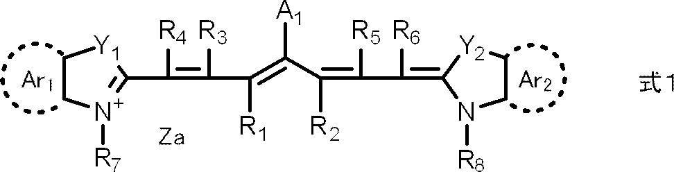
式1中、R1及びR2はそれぞれ独立に、水素原子又はアルキル基を表し、R1及びR2は互いに連結して環を形成してもよく、R3~R6はそれぞれ独立に、水素原子又はアルキル基を表し、R7及びR8はそれぞれ独立に、アルキル基又はアリール基を表し、Y1及びY2はそれぞれ独立に、酸素原子、硫黄原子、-NR0-又はジアルキルメチレン基を表し、R0は水素原子、アルキル基又はアリール基を表し、Ar1及びAr2はそれぞれ独立に、後述する式2で表される基を有していてもよいベンゼン環又はナフタレン環を形成する基を表し、A1は、-NR9R10、-X1-L1又は後述する式2で表される基を表し、R9及びR10はそれぞれ独立に、アルキル基、アリール基、アルコキシカルボニル基又はアリールスルホニル基を表し、X1は酸素原子又は硫黄原子を表し、L1は炭化水素基、ヘテロアリール基、又は、熱若しくは赤外線露光によりX1との結合が開裂する基を表し、Zaは電荷を中和する対イオンを表し、Ar1及びAr2の少なくとも一方に、下記式2で表される基を有する。
-X 式2
式2中、Xは、ハロゲン原子、-C(=O)-X2-R11、-C(=O)-NR12R13、-O-C(=O)-R14、-CN、-SO2NR15R16、又は、パーフルオロアルキル基を表し、X2は、単結合又は酸素原子を表し、R11及びR14はそれぞれ独立に、アルキル基又はアリール基を表し、R12、R13、R15及びR16はそれぞれ独立に、水素原子、アルキル基又はアリール基を表す。 - 前記式2のXが、フッ素原子、塩素原子、臭素原子又は-C(=O)OR17である請求項16に記載の機上現像型平版印刷版原版。
なお、R17は、アルキル基又はアリール基を表す。 - 式1におけるAr1及びAr2の少なくとも一方に、臭素原子を有する請求項16又は請求項17に記載の機上現像型平版印刷版原版。
- 前記電子供与型重合開始剤のHOMOが、-5.90eVより大きい請求項13又は請求項14に記載の機上現像型平版印刷版原版。
- 前記画像記録層が、電子受容型重合開始剤を含む請求項3又は請求項4に記載の機上現像型平版印刷版原版。
- 前記電子受容型重合開始剤が、オニウム塩化合物である請求項20に記載の機上現像型平版印刷版原版。
- 前記電子受容型重合開始剤が、下記式(II)で表される化合物を含む請求項20又は請求項21に記載の機上現像型平版印刷版原版。
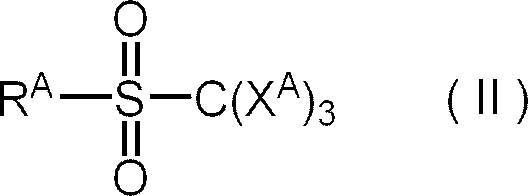
式(II)中、XAはハロゲン原子を表し、RAはアリール基を表す。 - 前記画像記録層が、酸発色剤を含む請求項3又は請求項4に記載の機上現像型平版印刷版原版。
- 前記酸発色剤が、下記式(Le-8)で表される化合物を含む請求項23に記載の機上現像型平版印刷版原版。
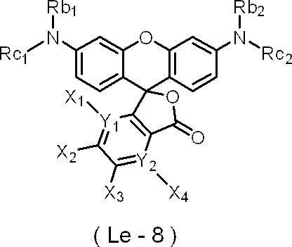
式(Le-8)中、X1~X4はそれぞれ独立に、水素原子、ハロゲン原子又はジアルキルアニリノ基を表し、Y1及びY2はそれぞれ独立に、C又はNを表し、Y1がNである場合は、X1は存在せず、Y2がNである場合は、X4は存在せず、Rb1及びRb2はそれぞれ独立に、水素原子、アルキル基、アリール基又はヘテロアリール基を表し、Rc1及びRc2はそれぞれ独立に、アリール基又はヘテロアリール基を表す。 - 前記Rc1及び前記Rc2がそれぞれ独立に、少なくとも1つのオルト位に置換基を有し、かつパラ位に電子供与性基を有するフェニル基である請求項24に記載の機上現像型平版印刷版原版。
- 前記酸発色剤が、下記式(Le-10)で表される化合物を含む請求項23に記載の機上現像型平版印刷版原版。

式(Le-10)中、Ar1はそれぞれ独立に、アリール基又はヘテロアリール基を表し、Ar2はそれぞれ独立に、少なくとも1つのオルト位に置換基を有するアリール基、又は、少なくとも1つのオルト位に置換基を有するヘテロアリール基を表す。 - 前記Ar1がそれぞれ独立に、電子供与性基を有するアリール基、又は、電子供与性基を有するヘテロアリール基であり、前記Ar2がそれぞれ独立に、少なくとも1つのオルト位に置換基を有し、かつパラ位に電子供与性基を有するフェニル基である請求項26に記載の機上現像型平版印刷版原版。
- 前記酸発色剤が、下記式(Le-11)で表される化合物を含む請求項23に記載の機上現像型平版印刷版原版。

式(Le-11)中、ERGはそれぞれ独立に、電子供与性基を表し、n11は、1~5の整数を表し、X1~X4はそれぞれ独立に、水素原子、ハロゲン原子又はジアルキルアニリノ基を表し、X5~X10はそれぞれ独立に、水素原子、ハロゲン原子又は一価の有機基を表し、Y1及びY2はそれぞれ独立に、C又はNを表し、Y1がNである場合は、X1は存在せず、Y2がNである場合は、X4は存在せず、Ra1は、水素原子、アルキル基又はアルコキシ基を表し、Rb2及びRb4はそれぞれ独立に、水素原子、アルキル基、アリール基又はヘテロアリール基を表す。 - 前記画像記録層が、赤外線吸収剤Cを更に含み、
前記赤外線吸収剤Aの最大吸収波長と前記赤外線吸収剤Bの最大吸収波長と前記赤外線吸収剤Cの最大吸収波長とがいずれも異なる請求項4に記載の機上現像型平版印刷版原版。 - 前記画像記録層が、重合性化合物を含む請求項3、請求項4及び請求項23~請求項29のいずれか1項に記載の機上現像型平版印刷版原版。
- 前記重合性化合物が、2官能以下の重合性化合物を含む請求項30に記載の機上現像型平版印刷版原版。
- 前記重合性化合物が、7官能以上の重合性化合物を含む請求項30又は請求項31に記載の機上現像型平版印刷版原版。
- 前記支持体と、前記画像記録層と、最外層と、をこの順で有する請求項3に記載の機上現像型平版印刷版原版。
- 前記最外層が、疎水性ポリマーを含む請求項4、請求項29又は請求項33に記載の機上現像型平版印刷版原版。
- 前記疎水性ポリマーが、疎水性ポリマー粒子である請求項34に記載の機上現像型平版印刷版原版。
- 前記支持体が、アルミニウム板と、前記アルミニウム板上に配置されたアルミニウムの陽極酸化皮膜とを有し、
前記陽極酸化皮膜が、前記アルミニウム板よりも前記画像記録層側に位置し、
前記陽極酸化皮膜が、前記画像記録層側の表面から深さ方向にのびるマイクロポアを有し、
前記マイクロポアの前記陽極酸化皮膜表面における平均径が、10nmを超え100nm以下である請求項3又は請求項4に記載の機上現像型平版印刷版原版。 - 前記マイクロポアが、前記陽極酸化皮膜表面から深さ10nm~1,000nmの位置までのびる大径孔部と、前記大径孔部の底部と連通し、連通位置から深さ20nm~2,000nmの位置までのびる小径孔部とから構成され、
前記大径孔部の前記陽極酸化皮膜表面における平均径が、15nm~100nmであり、
前記小径孔部の前記連通位置における平均径が、13nm以下である請求項36に記載の機上現像型平版印刷版原版。 - 請求項1~請求項37のいずれか1項に記載の機上現像型平版印刷版原版を、画像様に露光する工程と、
印刷機上で印刷インク及び湿し水よりなる群から選ばれた少なくとも一方を供給して非画像部の画像記録層を除去する工程と、を含む
平版印刷版の作製方法。 - 請求項1~請求項37のいずれか1項に記載の機上現像型平版印刷版原版を、画像様に露光する工程と、
印刷機上で印刷インク及び湿し水よりなる群から選ばれた少なくとも一方を供給して非画像部の画像記録層を除去し平版印刷版を作製する工程と、
得られた平版印刷版により印刷する工程と、を含む
平版印刷方法。
Priority Applications (4)
| Application Number | Priority Date | Filing Date | Title |
|---|---|---|---|
| CN202180059485.XA CN116133862B (zh) | 2020-07-21 | 2021-07-15 | 机上显影型平版印刷版原版、平版印刷版的制作方法及平版印刷方法 |
| EP21846380.0A EP4186708B1 (en) | 2020-07-21 | 2021-07-15 | On-press development type lithographic printing plate precursor, method of preparing a lithographic printing plate, and lithographic printing method |
| JP2022537966A JP7528223B2 (ja) | 2020-07-21 | 2021-07-15 | 機上現像型平版印刷版原版、平版印刷版の作製方法、及び、平版印刷方法 |
| US18/156,462 US20230150254A1 (en) | 2020-07-21 | 2023-01-19 | On-press development type lithographic printing plate precursor, method of preparing lithographic printing plate, and lithographic printing method |
Applications Claiming Priority (6)
| Application Number | Priority Date | Filing Date | Title |
|---|---|---|---|
| JP2020-124466 | 2020-07-21 | ||
| JP2020124466 | 2020-07-21 | ||
| JP2021-002134 | 2021-01-08 | ||
| JP2021002134 | 2021-01-08 | ||
| JP2021-061163 | 2021-03-31 | ||
| JP2021061163 | 2021-03-31 |
Related Child Applications (1)
| Application Number | Title | Priority Date | Filing Date |
|---|---|---|---|
| US18/156,462 Continuation US20230150254A1 (en) | 2020-07-21 | 2023-01-19 | On-press development type lithographic printing plate precursor, method of preparing lithographic printing plate, and lithographic printing method |
Publications (1)
| Publication Number | Publication Date |
|---|---|
| WO2022019217A1 true WO2022019217A1 (ja) | 2022-01-27 |
Family
ID=79729570
Family Applications (1)
| Application Number | Title | Priority Date | Filing Date |
|---|---|---|---|
| PCT/JP2021/026683 Ceased WO2022019217A1 (ja) | 2020-07-21 | 2021-07-15 | 機上現像型平版印刷版原版、平版印刷版の作製方法、及び、平版印刷方法 |
Country Status (5)
| Country | Link |
|---|---|
| US (1) | US20230150254A1 (ja) |
| EP (1) | EP4186708B1 (ja) |
| JP (1) | JP7528223B2 (ja) |
| CN (1) | CN116133862B (ja) |
| WO (1) | WO2022019217A1 (ja) |
Cited By (7)
| Publication number | Priority date | Publication date | Assignee | Title |
|---|---|---|---|---|
| EP4438301A1 (en) | 2023-03-30 | 2024-10-02 | FUJIFILM Corporation | On-press development type lithographic printing plate precursor, method of preparing lithographic printing plate, and lithographic printing method |
| EP4438300A1 (en) | 2023-03-30 | 2024-10-02 | FUJIFILM Corporation | On-press development type lithographic printing plate precursor, method of preparing lithographic printing plate, lithographic printing method, and compound |
| WO2025013922A1 (ja) | 2023-07-11 | 2025-01-16 | 富士フイルム株式会社 | 機上現像型平版印刷版原版、平版印刷版の作製方法、及び平版印刷方法 |
| WO2025013910A1 (ja) | 2023-07-11 | 2025-01-16 | 富士フイルム株式会社 | 機上現像型平版印刷版原版、平版印刷版の作製方法、平版印刷方法、及び化合物 |
| WO2025094764A1 (ja) | 2023-10-31 | 2025-05-08 | 富士フイルム株式会社 | 機上現像型平版印刷版原版、平版印刷版の作製方法、及び平版印刷方法 |
| EP4610049A1 (en) | 2024-02-29 | 2025-09-03 | FUJIFILM Corporation | On-press development type lithographic printing plate precursor, method of preparing lithographic printing plate, lithographic printing method, and compound |
| EP4755636A1 (en) | 2024-12-06 | 2026-06-10 | FUJIFILM Corporation | Lithographic printing plate precursor and method of preparing lithographic printing plate |
Citations (57)
| Publication number | Priority date | Publication date | Assignee | Title |
|---|---|---|---|---|
| US3458311A (en) | 1966-06-27 | 1969-07-29 | Du Pont | Photopolymerizable elements with solvent removable protective layers |
| JPS5549729B2 (ja) | 1973-02-07 | 1980-12-13 | ||
| JPS61166544A (ja) | 1985-01-18 | 1986-07-28 | Fuji Photo Film Co Ltd | 光可溶化組成物 |
| JPS63137226A (ja) * | 1986-11-29 | 1988-06-09 | Fuji Photo Film Co Ltd | 光重合性組成物 |
| JPH02304441A (ja) | 1989-05-18 | 1990-12-18 | Fuji Photo Film Co Ltd | 感光性平版印刷版 |
| JPH055005A (ja) | 1991-04-26 | 1993-01-14 | Kyowa Hakko Kogyo Co Ltd | 光重合開始剤およびこれを含有する光重合性組成物 |
| JPH0545885A (ja) | 1991-08-19 | 1993-02-26 | Fuji Photo Film Co Ltd | 感光性平版印刷版 |
| JPH0635174A (ja) | 1992-07-16 | 1994-02-10 | Fuji Photo Film Co Ltd | 感光性平版印刷版およびその処理方法 |
| JPH08108621A (ja) | 1994-10-06 | 1996-04-30 | Konica Corp | 画像記録媒体及びそれを用いる画像形成方法 |
| JPH09123387A (ja) | 1995-10-24 | 1997-05-13 | Agfa Gevaert Nv | 印刷機上現像を含む平版印刷版の製造方法 |
| JPH09131850A (ja) | 1995-10-24 | 1997-05-20 | Agfa Gevaert Nv | 印刷機上現像を含む平版印刷版の製造方法 |
| JPH09171249A (ja) | 1995-11-09 | 1997-06-30 | Agfa Gevaert Nv | 感熱性像形成要素およびそれを用いて印刷版を製造する方法 |
| JPH09171250A (ja) | 1995-11-09 | 1997-06-30 | Agfa Gevaert Nv | 感熱性像形成要素およびそれらを用いて印刷版を製造する方法 |
| JPH10282679A (ja) | 1997-04-08 | 1998-10-23 | Fuji Photo Film Co Ltd | ネガ型感光性平版印刷版 |
| JP2001133969A (ja) | 1999-11-01 | 2001-05-18 | Fuji Photo Film Co Ltd | ネガ型平版印刷版原版 |
| JP2001222101A (ja) | 2000-02-09 | 2001-08-17 | Mitsubishi Paper Mills Ltd | 感光性組成物および感光性平版印刷版材料 |
| JP2001277740A (ja) | 2000-01-27 | 2001-10-10 | Fuji Photo Film Co Ltd | 平版印刷版用原版 |
| JP2001277742A (ja) | 2000-01-27 | 2001-10-10 | Fuji Photo Film Co Ltd | 平版印刷版用原版 |
| JP2002023360A (ja) | 2000-07-12 | 2002-01-23 | Fuji Photo Film Co Ltd | ネガ型画像記録材料 |
| JP2002040638A (ja) | 2000-07-25 | 2002-02-06 | Fuji Photo Film Co Ltd | ネガ型画像記録材料及び画像形成方法 |
| JP2002278057A (ja) | 2001-01-15 | 2002-09-27 | Fuji Photo Film Co Ltd | ネガ型画像記録材料及びシアニン色素 |
| JP2002328465A (ja) | 2001-04-27 | 2002-11-15 | Fuji Photo Film Co Ltd | 平版印刷版原版 |
| EP0931647B1 (en) | 1998-01-23 | 2003-04-02 | Agfa-Gevaert | A heat sensitive element and a method for producing lithographic plates therewith |
| JP2005125749A (ja) | 2003-09-30 | 2005-05-19 | Fuji Photo Film Co Ltd | 平版印刷版原版および平版印刷方法 |
| JP2005238816A (ja) | 2003-07-22 | 2005-09-08 | Fuji Photo Film Co Ltd | 平版印刷版原版および平版印刷方法 |
| JP2005250216A (ja) | 2004-03-05 | 2005-09-15 | Fuji Photo Film Co Ltd | ネガ型平版印刷版原版およびこれを用いた平版印刷版の製版方法 |
| JP2006188038A (ja) | 2004-12-10 | 2006-07-20 | Fuji Photo Film Co Ltd | 平版印刷版原版および製版方法 |
| JP2006215263A (ja) | 2005-02-03 | 2006-08-17 | Fuji Photo Film Co Ltd | 平版印刷版原版 |
| JP2006239867A (ja) | 2005-02-28 | 2006-09-14 | Fuji Photo Film Co Ltd | 平版印刷版原版および平版印刷方法 |
| JP2006259137A (ja) | 2005-03-16 | 2006-09-28 | Fuji Photo Film Co Ltd | ネガ型平版印刷版原版 |
| JP2006297907A (ja) | 2005-02-28 | 2006-11-02 | Fuji Photo Film Co Ltd | 平版印刷版原版、平版印刷版原版の製造方法および平版印刷方法 |
| JP2007050660A (ja) | 2005-08-19 | 2007-03-01 | Fujifilm Corp | 平版印刷版原版および平版印刷方法 |
| JP2007090850A (ja) | 2005-08-29 | 2007-04-12 | Fujifilm Corp | 平版印刷版原版、平版印刷方法、及び新規シアニン色素 |
| JP2008503365A (ja) | 2004-06-17 | 2008-02-07 | イーストマン コダック カンパニー | 耐溶剤性高分子バインダーを有する画像形成可能要素 |
| JP2008195018A (ja) | 2007-02-15 | 2008-08-28 | Fujifilm Corp | 平版印刷版原版および平版印刷方法 |
| JP2008284817A (ja) | 2007-05-18 | 2008-11-27 | Fujifilm Corp | 平版印刷版原版、及びそれを用いた印刷方法 |
| JP2008284858A (ja) | 2007-05-21 | 2008-11-27 | Fujifilm Corp | 平版印刷版原版、及びそれを用いた印刷方法 |
| JP2008544322A (ja) | 2005-06-21 | 2008-12-04 | アグフア・グラフイクス・ナームローゼ・フエンノートシヤツプ | 感熱性像形成要素 |
| JP2009090645A (ja) | 2007-09-20 | 2009-04-30 | Fujifilm Corp | 平版印刷版原版、及びそれを用いた印刷方法 |
| JP2009208458A (ja) | 2007-06-21 | 2009-09-17 | Fujifilm Corp | 平版印刷版原版および平版印刷方法 |
| US20090269699A1 (en) | 2008-04-29 | 2009-10-29 | Munnelly Heidi M | On-press developable elements and methods of use |
| JP2012501878A (ja) * | 2008-09-04 | 2012-01-26 | イーストマン コダック カンパニー | ネガ型画像形成性要素及び使用方法 |
| JP2012148555A (ja) | 2010-12-28 | 2012-08-09 | Fujifilm Corp | 平版印刷版原版及びその平版印刷方法 |
| JP2012206495A (ja) | 2010-04-30 | 2012-10-25 | Fujifilm Corp | 平版印刷版原版、その製版方法、及び、多価イソシアネート化合物 |
| WO2016027886A1 (ja) | 2014-08-22 | 2016-02-25 | 富士フイルム株式会社 | 発色組成物、平版印刷版原版、平版印刷版の製版方法、及び、発色剤 |
| WO2017141882A1 (ja) | 2016-02-19 | 2017-08-24 | 富士フイルム株式会社 | 発色組成物、平版印刷版原版、平版印刷版の作製方法、及び発色性化合物 |
| US20180207925A1 (en) * | 2015-07-23 | 2018-07-26 | Agfa Nv | A lithographic printing plate precursor comprising graphite oxide |
| WO2018230412A1 (ja) * | 2017-06-12 | 2018-12-20 | 富士フイルム株式会社 | 平版印刷版原版、平版印刷版の製版方法、有機ポリマー粒子、及び、感光性樹脂組成物 |
| WO2019013268A1 (ja) | 2017-07-13 | 2019-01-17 | 富士フイルム株式会社 | 平版印刷版原版、及び、平版印刷版の作製方法 |
| JP6461447B1 (ja) * | 2017-09-29 | 2019-01-30 | 富士フイルム株式会社 | 平版印刷版原版、平版印刷版の作製方法及び平版印刷方法 |
| WO2019150788A1 (ja) * | 2018-01-31 | 2019-08-08 | 富士フイルム株式会社 | 平版印刷版原版、及び、平版印刷版の作製方法 |
| JP2019162855A (ja) | 2017-08-31 | 2019-09-26 | 富士フイルム株式会社 | 平版印刷版原版、平版印刷版の製造方法、印刷方法 |
| WO2019219560A1 (en) | 2018-05-14 | 2019-11-21 | Agfa Nv | A lithographic printing plate precursor |
| JP2020069790A (ja) * | 2018-10-31 | 2020-05-07 | 富士フイルム株式会社 | 平版印刷版原版、平版印刷版の作製方法、及び、平版印刷方法 |
| JP2020124466A (ja) | 2019-02-05 | 2020-08-20 | 淳也 古賀 | 水泳練習用具 |
| JP2021002134A (ja) | 2019-06-20 | 2021-01-07 | 株式会社ソニー・インタラクティブエンタテインメント | サーバ装置、コンテンツ送信方法およびダウンロード管理方法 |
| JP2021061163A (ja) | 2019-10-07 | 2021-04-15 | 日立グローバルライフソリューションズ株式会社 | 電磁誘導加熱装置 |
Family Cites Families (12)
| Publication number | Priority date | Publication date | Assignee | Title |
|---|---|---|---|---|
| US20050153239A1 (en) * | 2004-01-09 | 2005-07-14 | Fuji Photo Film Co., Ltd. | Lithographic printing plate precursor and lithographic printing method using the same |
| US8900798B2 (en) * | 2010-10-18 | 2014-12-02 | Eastman Kodak Company | On-press developable lithographic printing plate precursors |
| US20130101938A1 (en) * | 2011-10-20 | 2013-04-25 | Koji Hayashi | On-press developable lithographic printing plate precursors |
| EP2963495B1 (en) * | 2013-02-27 | 2019-06-05 | FUJIFILM Corporation | Infrared-sensitive chromogenic composition, infrared-curable chromogenic composition, lithographic printing plate precursor, and plate formation method |
| EP3511173B1 (en) * | 2017-10-31 | 2020-08-05 | FUJIFILM Corporation | Lithographic printing plate precursor, lithographic printing plate manufacturing method, printing method and aluminum support manufacturing method |
| WO2020090995A1 (ja) * | 2018-10-31 | 2020-05-07 | 富士フイルム株式会社 | 平版印刷版原版、平版印刷版の作製方法、及び、平版印刷方法 |
| WO2020090996A1 (ja) * | 2018-10-31 | 2020-05-07 | 富士フイルム株式会社 | 平版印刷版原版、平版印刷版の作製方法、及び、平版印刷方法 |
| JP2020093518A (ja) * | 2018-11-30 | 2020-06-18 | 富士フイルム株式会社 | 平版印刷版原版、平版印刷版の作製方法、及び、平版印刷方法 |
| CN114096914A (zh) * | 2019-06-28 | 2022-02-25 | 富士胶片株式会社 | 机上显影型平版印刷版原版、平版印刷版的制作方法及平版印刷方法 |
| WO2021065278A1 (ja) * | 2019-09-30 | 2021-04-08 | 富士フイルム株式会社 | 平版印刷版原版、平版印刷版の作製方法、及び、平版印刷方法 |
| US20230311474A1 (en) * | 2020-06-24 | 2023-10-05 | Agfa Offset Bv | A Lithographic Printing Plate Precursor |
| EP4171957B1 (en) * | 2020-06-24 | 2025-02-12 | Eco3 Bv | A lithographic printing plate precursor |
-
2021
- 2021-07-15 EP EP21846380.0A patent/EP4186708B1/en active Active
- 2021-07-15 WO PCT/JP2021/026683 patent/WO2022019217A1/ja not_active Ceased
- 2021-07-15 JP JP2022537966A patent/JP7528223B2/ja active Active
- 2021-07-15 CN CN202180059485.XA patent/CN116133862B/zh active Active
-
2023
- 2023-01-19 US US18/156,462 patent/US20230150254A1/en active Pending
Patent Citations (57)
| Publication number | Priority date | Publication date | Assignee | Title |
|---|---|---|---|---|
| US3458311A (en) | 1966-06-27 | 1969-07-29 | Du Pont | Photopolymerizable elements with solvent removable protective layers |
| JPS5549729B2 (ja) | 1973-02-07 | 1980-12-13 | ||
| JPS61166544A (ja) | 1985-01-18 | 1986-07-28 | Fuji Photo Film Co Ltd | 光可溶化組成物 |
| JPS63137226A (ja) * | 1986-11-29 | 1988-06-09 | Fuji Photo Film Co Ltd | 光重合性組成物 |
| JPH02304441A (ja) | 1989-05-18 | 1990-12-18 | Fuji Photo Film Co Ltd | 感光性平版印刷版 |
| JPH055005A (ja) | 1991-04-26 | 1993-01-14 | Kyowa Hakko Kogyo Co Ltd | 光重合開始剤およびこれを含有する光重合性組成物 |
| JPH0545885A (ja) | 1991-08-19 | 1993-02-26 | Fuji Photo Film Co Ltd | 感光性平版印刷版 |
| JPH0635174A (ja) | 1992-07-16 | 1994-02-10 | Fuji Photo Film Co Ltd | 感光性平版印刷版およびその処理方法 |
| JPH08108621A (ja) | 1994-10-06 | 1996-04-30 | Konica Corp | 画像記録媒体及びそれを用いる画像形成方法 |
| JPH09123387A (ja) | 1995-10-24 | 1997-05-13 | Agfa Gevaert Nv | 印刷機上現像を含む平版印刷版の製造方法 |
| JPH09131850A (ja) | 1995-10-24 | 1997-05-20 | Agfa Gevaert Nv | 印刷機上現像を含む平版印刷版の製造方法 |
| JPH09171249A (ja) | 1995-11-09 | 1997-06-30 | Agfa Gevaert Nv | 感熱性像形成要素およびそれを用いて印刷版を製造する方法 |
| JPH09171250A (ja) | 1995-11-09 | 1997-06-30 | Agfa Gevaert Nv | 感熱性像形成要素およびそれらを用いて印刷版を製造する方法 |
| JPH10282679A (ja) | 1997-04-08 | 1998-10-23 | Fuji Photo Film Co Ltd | ネガ型感光性平版印刷版 |
| EP0931647B1 (en) | 1998-01-23 | 2003-04-02 | Agfa-Gevaert | A heat sensitive element and a method for producing lithographic plates therewith |
| JP2001133969A (ja) | 1999-11-01 | 2001-05-18 | Fuji Photo Film Co Ltd | ネガ型平版印刷版原版 |
| JP2001277742A (ja) | 2000-01-27 | 2001-10-10 | Fuji Photo Film Co Ltd | 平版印刷版用原版 |
| JP2001277740A (ja) | 2000-01-27 | 2001-10-10 | Fuji Photo Film Co Ltd | 平版印刷版用原版 |
| JP2001222101A (ja) | 2000-02-09 | 2001-08-17 | Mitsubishi Paper Mills Ltd | 感光性組成物および感光性平版印刷版材料 |
| JP2002023360A (ja) | 2000-07-12 | 2002-01-23 | Fuji Photo Film Co Ltd | ネガ型画像記録材料 |
| JP2002040638A (ja) | 2000-07-25 | 2002-02-06 | Fuji Photo Film Co Ltd | ネガ型画像記録材料及び画像形成方法 |
| JP2002278057A (ja) | 2001-01-15 | 2002-09-27 | Fuji Photo Film Co Ltd | ネガ型画像記録材料及びシアニン色素 |
| JP2002328465A (ja) | 2001-04-27 | 2002-11-15 | Fuji Photo Film Co Ltd | 平版印刷版原版 |
| JP2005238816A (ja) | 2003-07-22 | 2005-09-08 | Fuji Photo Film Co Ltd | 平版印刷版原版および平版印刷方法 |
| JP2005125749A (ja) | 2003-09-30 | 2005-05-19 | Fuji Photo Film Co Ltd | 平版印刷版原版および平版印刷方法 |
| JP2005250216A (ja) | 2004-03-05 | 2005-09-15 | Fuji Photo Film Co Ltd | ネガ型平版印刷版原版およびこれを用いた平版印刷版の製版方法 |
| JP2008503365A (ja) | 2004-06-17 | 2008-02-07 | イーストマン コダック カンパニー | 耐溶剤性高分子バインダーを有する画像形成可能要素 |
| JP2006188038A (ja) | 2004-12-10 | 2006-07-20 | Fuji Photo Film Co Ltd | 平版印刷版原版および製版方法 |
| JP2006215263A (ja) | 2005-02-03 | 2006-08-17 | Fuji Photo Film Co Ltd | 平版印刷版原版 |
| JP2006239867A (ja) | 2005-02-28 | 2006-09-14 | Fuji Photo Film Co Ltd | 平版印刷版原版および平版印刷方法 |
| JP2006297907A (ja) | 2005-02-28 | 2006-11-02 | Fuji Photo Film Co Ltd | 平版印刷版原版、平版印刷版原版の製造方法および平版印刷方法 |
| JP2006259137A (ja) | 2005-03-16 | 2006-09-28 | Fuji Photo Film Co Ltd | ネガ型平版印刷版原版 |
| JP2008544322A (ja) | 2005-06-21 | 2008-12-04 | アグフア・グラフイクス・ナームローゼ・フエンノートシヤツプ | 感熱性像形成要素 |
| JP2007050660A (ja) | 2005-08-19 | 2007-03-01 | Fujifilm Corp | 平版印刷版原版および平版印刷方法 |
| JP2007090850A (ja) | 2005-08-29 | 2007-04-12 | Fujifilm Corp | 平版印刷版原版、平版印刷方法、及び新規シアニン色素 |
| JP2008195018A (ja) | 2007-02-15 | 2008-08-28 | Fujifilm Corp | 平版印刷版原版および平版印刷方法 |
| JP2008284817A (ja) | 2007-05-18 | 2008-11-27 | Fujifilm Corp | 平版印刷版原版、及びそれを用いた印刷方法 |
| JP2008284858A (ja) | 2007-05-21 | 2008-11-27 | Fujifilm Corp | 平版印刷版原版、及びそれを用いた印刷方法 |
| JP2009208458A (ja) | 2007-06-21 | 2009-09-17 | Fujifilm Corp | 平版印刷版原版および平版印刷方法 |
| JP2009090645A (ja) | 2007-09-20 | 2009-04-30 | Fujifilm Corp | 平版印刷版原版、及びそれを用いた印刷方法 |
| US20090269699A1 (en) | 2008-04-29 | 2009-10-29 | Munnelly Heidi M | On-press developable elements and methods of use |
| JP2012501878A (ja) * | 2008-09-04 | 2012-01-26 | イーストマン コダック カンパニー | ネガ型画像形成性要素及び使用方法 |
| JP2012206495A (ja) | 2010-04-30 | 2012-10-25 | Fujifilm Corp | 平版印刷版原版、その製版方法、及び、多価イソシアネート化合物 |
| JP2012148555A (ja) | 2010-12-28 | 2012-08-09 | Fujifilm Corp | 平版印刷版原版及びその平版印刷方法 |
| WO2016027886A1 (ja) | 2014-08-22 | 2016-02-25 | 富士フイルム株式会社 | 発色組成物、平版印刷版原版、平版印刷版の製版方法、及び、発色剤 |
| US20180207925A1 (en) * | 2015-07-23 | 2018-07-26 | Agfa Nv | A lithographic printing plate precursor comprising graphite oxide |
| WO2017141882A1 (ja) | 2016-02-19 | 2017-08-24 | 富士フイルム株式会社 | 発色組成物、平版印刷版原版、平版印刷版の作製方法、及び発色性化合物 |
| WO2018230412A1 (ja) * | 2017-06-12 | 2018-12-20 | 富士フイルム株式会社 | 平版印刷版原版、平版印刷版の製版方法、有機ポリマー粒子、及び、感光性樹脂組成物 |
| WO2019013268A1 (ja) | 2017-07-13 | 2019-01-17 | 富士フイルム株式会社 | 平版印刷版原版、及び、平版印刷版の作製方法 |
| JP2019162855A (ja) | 2017-08-31 | 2019-09-26 | 富士フイルム株式会社 | 平版印刷版原版、平版印刷版の製造方法、印刷方法 |
| JP6461447B1 (ja) * | 2017-09-29 | 2019-01-30 | 富士フイルム株式会社 | 平版印刷版原版、平版印刷版の作製方法及び平版印刷方法 |
| WO2019150788A1 (ja) * | 2018-01-31 | 2019-08-08 | 富士フイルム株式会社 | 平版印刷版原版、及び、平版印刷版の作製方法 |
| WO2019219560A1 (en) | 2018-05-14 | 2019-11-21 | Agfa Nv | A lithographic printing plate precursor |
| JP2020069790A (ja) * | 2018-10-31 | 2020-05-07 | 富士フイルム株式会社 | 平版印刷版原版、平版印刷版の作製方法、及び、平版印刷方法 |
| JP2020124466A (ja) | 2019-02-05 | 2020-08-20 | 淳也 古賀 | 水泳練習用具 |
| JP2021002134A (ja) | 2019-06-20 | 2021-01-07 | 株式会社ソニー・インタラクティブエンタテインメント | サーバ装置、コンテンツ送信方法およびダウンロード管理方法 |
| JP2021061163A (ja) | 2019-10-07 | 2021-04-15 | 日立グローバルライフソリューションズ株式会社 | 電磁誘導加熱装置 |
Non-Patent Citations (3)
| Title |
|---|
| CHARLES M. HANSEN: "A Users Handbook", vol. VII, 2007, CRC PRESS, article "Hansen Solubility Parameters", pages: 698 - 711 |
| ORGANIC LETTERS, vol. 13, 2011, pages 6354 - 6357 |
| RESEARCH DISCLOSURE, no. 33303, January 1992 (1992-01-01) |
Cited By (7)
| Publication number | Priority date | Publication date | Assignee | Title |
|---|---|---|---|---|
| EP4438301A1 (en) | 2023-03-30 | 2024-10-02 | FUJIFILM Corporation | On-press development type lithographic printing plate precursor, method of preparing lithographic printing plate, and lithographic printing method |
| EP4438300A1 (en) | 2023-03-30 | 2024-10-02 | FUJIFILM Corporation | On-press development type lithographic printing plate precursor, method of preparing lithographic printing plate, lithographic printing method, and compound |
| WO2025013922A1 (ja) | 2023-07-11 | 2025-01-16 | 富士フイルム株式会社 | 機上現像型平版印刷版原版、平版印刷版の作製方法、及び平版印刷方法 |
| WO2025013910A1 (ja) | 2023-07-11 | 2025-01-16 | 富士フイルム株式会社 | 機上現像型平版印刷版原版、平版印刷版の作製方法、平版印刷方法、及び化合物 |
| WO2025094764A1 (ja) | 2023-10-31 | 2025-05-08 | 富士フイルム株式会社 | 機上現像型平版印刷版原版、平版印刷版の作製方法、及び平版印刷方法 |
| EP4610049A1 (en) | 2024-02-29 | 2025-09-03 | FUJIFILM Corporation | On-press development type lithographic printing plate precursor, method of preparing lithographic printing plate, lithographic printing method, and compound |
| EP4755636A1 (en) | 2024-12-06 | 2026-06-10 | FUJIFILM Corporation | Lithographic printing plate precursor and method of preparing lithographic printing plate |
Also Published As
| Publication number | Publication date |
|---|---|
| JP7528223B2 (ja) | 2024-08-05 |
| EP4186708A4 (en) | 2023-12-13 |
| JPWO2022019217A1 (ja) | 2022-01-27 |
| EP4186708A1 (en) | 2023-05-31 |
| CN116133862A (zh) | 2023-05-16 |
| EP4186708B1 (en) | 2026-03-04 |
| CN116133862B (zh) | 2025-10-10 |
| US20230150254A1 (en) | 2023-05-18 |
Similar Documents
| Publication | Publication Date | Title |
|---|---|---|
| JP7096435B2 (ja) | 機上現像型平版印刷版原版、平版印刷版の作製方法、及び、平版印刷方法 | |
| CN110505962B (zh) | 平版印刷版原版和平版印刷版的制作方法 | |
| JP7528223B2 (ja) | 機上現像型平版印刷版原版、平版印刷版の作製方法、及び、平版印刷方法 | |
| JPWO2017141882A1 (ja) | 発色組成物、平版印刷版原版、平版印刷版の作製方法、及び発色性化合物 | |
| WO2020262691A1 (ja) | 機上現像型平版印刷版原版、平版印刷版の作製方法、及び、平版印刷方法 | |
| WO2020262696A1 (ja) | 機上現像型平版印刷版原版、平版印刷版の作製方法、及び、平版印刷方法 | |
| JP7397164B2 (ja) | 平版印刷版原版、平版印刷版の作製方法、及び、平版印刷方法 | |
| WO2020262689A1 (ja) | 機上現像型平版印刷版原版、平版印刷版の作製方法、及び、平版印刷方法 | |
| EP3904099B1 (en) | Lithographic printing plate precursor, method of preparing a lithographic printing plate, and lithographic printing method | |
| JP7467629B2 (ja) | 機上現像型平版印刷版原版、平版印刷版の作製方法、及び、平版印刷方法 | |
| US20260131566A1 (en) | On-press development type lithographic printing plate precursor, method of preparing lithographic printing plate, and lithographic printing method | |
| WO2020026810A1 (ja) | 機上現像型平版印刷版原版、平版印刷版の作製方法、及び、平版印刷方法 | |
| WO2023032681A1 (ja) | 積層体 | |
| JP2020093518A (ja) | 平版印刷版原版、平版印刷版の作製方法、及び、平版印刷方法 | |
| WO2021065152A1 (ja) | 平版印刷版原版、平版印刷版の作製方法、及び、平版印刷方法 | |
| JP7726979B2 (ja) | 機上現像型平版印刷版原版、平版印刷版の作製方法、平版印刷方法、及び、呈色剤 | |
| WO2021065279A1 (ja) | 平版印刷版原版、平版印刷版の作製方法、及び、平版印刷方法 | |
| EP4438301B1 (en) | On-press development type lithographic printing plate precursor, method of preparing lithographic printing plate, and lithographic printing method | |
| EP4438300A1 (en) | On-press development type lithographic printing plate precursor, method of preparing lithographic printing plate, lithographic printing method, and compound | |
| WO2025182736A1 (ja) | 機上現像型平版印刷版原版、平版印刷版の作製方法、平版印刷方法、及び、積層体 | |
| WO2025094764A1 (ja) | 機上現像型平版印刷版原版、平版印刷版の作製方法、及び平版印刷方法 | |
| CN116774521A (zh) | 平版印刷版原版、平版印刷版的制作方法及平版印刷方法 | |
| WO2020262688A1 (ja) | 平版印刷版原版、平版印刷版の作製方法、及び、平版印刷方法 | |
| JP2021189319A (ja) | 機上現像型平版印刷版原版、平版印刷版の作製方法、並びに、平版印刷方法 | |
| WO2020262687A1 (ja) | 平版印刷版原版、平版印刷版の作製方法、及び平版印刷方法 |
Legal Events
| Date | Code | Title | Description |
|---|---|---|---|
| 121 | Ep: the epo has been informed by wipo that ep was designated in this application |
Ref document number: 21846380 Country of ref document: EP Kind code of ref document: A1 |
|
| ENP | Entry into the national phase |
Ref document number: 2022537966 Country of ref document: JP Kind code of ref document: A |
|
| NENP | Non-entry into the national phase |
Ref country code: DE |
|
| ENP | Entry into the national phase |
Ref document number: 2021846380 Country of ref document: EP Effective date: 20230221 |
|
| WWG | Wipo information: grant in national office |
Ref document number: 202180059485.X Country of ref document: CN |
|
| WWG | Wipo information: grant in national office |
Ref document number: 2021846380 Country of ref document: EP |