WO2022014719A1 - 熱交換器のヘッダプレート構造 - Google Patents
熱交換器のヘッダプレート構造 Download PDFInfo
- Publication number
- WO2022014719A1 WO2022014719A1 PCT/JP2021/026900 JP2021026900W WO2022014719A1 WO 2022014719 A1 WO2022014719 A1 WO 2022014719A1 JP 2021026900 W JP2021026900 W JP 2021026900W WO 2022014719 A1 WO2022014719 A1 WO 2022014719A1
- Authority
- WO
- WIPO (PCT)
- Prior art keywords
- tube insertion
- insertion hole
- burring
- header plate
- height
- Prior art date
- Legal status (The legal status is an assumption and is not a legal conclusion. Google has not performed a legal analysis and makes no representation as to the accuracy of the status listed.)
- Ceased
Links
Images


Classifications
-
- F—MECHANICAL ENGINEERING; LIGHTING; HEATING; WEAPONS; BLASTING
- F28—HEAT EXCHANGE IN GENERAL
- F28F—DETAILS OF HEAT-EXCHANGE AND HEAT-TRANSFER APPARATUS, OF GENERAL APPLICATION
- F28F9/00—Casings; Header boxes; Auxiliary supports for elements; Auxiliary members within casings
- F28F9/02—Header boxes; End plates
- F28F9/0202—Header boxes having their inner space divided by partitions
-
- F—MECHANICAL ENGINEERING; LIGHTING; HEATING; WEAPONS; BLASTING
- F28—HEAT EXCHANGE IN GENERAL
- F28F—DETAILS OF HEAT-EXCHANGE AND HEAT-TRANSFER APPARATUS, OF GENERAL APPLICATION
- F28F9/00—Casings; Header boxes; Auxiliary supports for elements; Auxiliary members within casings
- F28F9/02—Header boxes; End plates
- F28F9/0219—Arrangements for sealing end plates into casing or header box; Header box sub-elements
- F28F9/0224—Header boxes formed by sealing end plates into covers
- F28F9/0226—Header boxes formed by sealing end plates into covers with resilient gaskets
-
- F—MECHANICAL ENGINEERING; LIGHTING; HEATING; WEAPONS; BLASTING
- F28—HEAT EXCHANGE IN GENERAL
- F28D—HEAT-EXCHANGE APPARATUS, NOT PROVIDED FOR IN ANOTHER SUBCLASS, IN WHICH THE HEAT-EXCHANGE MEDIA DO NOT COME INTO DIRECT CONTACT
- F28D1/00—Heat-exchange apparatus having stationary conduit assemblies for one heat-exchange medium only, the media being in contact with different sides of the conduit wall, in which the other heat-exchange medium is a large body of fluid, e.g. domestic or motor car radiators
- F28D1/02—Heat-exchange apparatus having stationary conduit assemblies for one heat-exchange medium only, the media being in contact with different sides of the conduit wall, in which the other heat-exchange medium is a large body of fluid, e.g. domestic or motor car radiators with heat-exchange conduits immersed in the body of fluid
- F28D1/04—Heat-exchange apparatus having stationary conduit assemblies for one heat-exchange medium only, the media being in contact with different sides of the conduit wall, in which the other heat-exchange medium is a large body of fluid, e.g. domestic or motor car radiators with heat-exchange conduits immersed in the body of fluid with tubular conduits
- F28D1/053—Heat-exchange apparatus having stationary conduit assemblies for one heat-exchange medium only, the media being in contact with different sides of the conduit wall, in which the other heat-exchange medium is a large body of fluid, e.g. domestic or motor car radiators with heat-exchange conduits immersed in the body of fluid with tubular conduits the conduits being straight
- F28D1/0535—Heat-exchange apparatus having stationary conduit assemblies for one heat-exchange medium only, the media being in contact with different sides of the conduit wall, in which the other heat-exchange medium is a large body of fluid, e.g. domestic or motor car radiators with heat-exchange conduits immersed in the body of fluid with tubular conduits the conduits being straight the conduits having a non-circular cross-section
- F28D1/05366—Assemblies of conduits connected to common headers, e.g. core type radiators
- F28D1/05391—Assemblies of conduits connected to common headers, e.g. core type radiators with multiple rows of conduits or with multi-channel conduits combined with a particular flow pattern, e.g. multi-row multi-stage radiators
-
- F—MECHANICAL ENGINEERING; LIGHTING; HEATING; WEAPONS; BLASTING
- F28—HEAT EXCHANGE IN GENERAL
- F28F—DETAILS OF HEAT-EXCHANGE AND HEAT-TRANSFER APPARATUS, OF GENERAL APPLICATION
- F28F2265/00—Safety or protection arrangements; Arrangements for preventing malfunction
- F28F2265/26—Safety or protection arrangements; Arrangements for preventing malfunction for allowing differential expansion between elements
-
- F—MECHANICAL ENGINEERING; LIGHTING; HEATING; WEAPONS; BLASTING
- F28—HEAT EXCHANGE IN GENERAL
- F28F—DETAILS OF HEAT-EXCHANGE AND HEAT-TRANSFER APPARATUS, OF GENERAL APPLICATION
- F28F2275/00—Fastening; Joining
- F28F2275/04—Fastening; Joining by brazing
Definitions
- the present invention relates to a header plate structure of a heat exchanger that is most suitable for a heat exchanger having a core divided into a plurality of parts, and more particularly to a structure that reduces thermal stress and strain applied to the flat tube and the header plate.
- Patent Document 1 is known as a heat exchanger in which a core partitioned in a plurality of directions in the longitudinal direction of a tank is formed.
- the core of this heat exchanger is formed by a large number of parallel flat tubes 32, and the tip of each flat tube 32 is formed in the bottom surface 10 of the pair of header plates 1. It is inserted into the tube insertion hole 4 that has been formed. Corrugated fins 33 are arranged between the flat tubes.
- the tank body 21 is fitted to the pair of header plates 1 to form a tank.
- the tank body 21 is fixed to the header plate 1 by caulking the claw portion 13 provided on the header plate 1 to the small flange 25 of the tank body 21.
- the tank body 21 is formed with a pair of partition portions 22 for partitioning the flow path of the heat medium flowing inside the core.
- a dummy tube insertion hole 6 is formed in the bottom surface 10 of the header plate 1 in a portion of the tank body 21 where the pair of partition portions 22 are located, and a flat tube is formed in the dummy tube insertion hole 6. 32 is inserted. The heat medium does not flow into the flat tube 32 inserted through the dummy tube insertion hole 6.
- the longitudinal direction of the tank body 21 is divided into the first tank portion 23 and the second tank portion 24 with the dummy tube insertion hole 6 as a boundary.
- the core portion partitioned by the first tank portion 23 forms the first core 34
- the core portion partitioned by the second tank portion 24 forms the second core 35. It becomes possible to distribute different heat media to the first core 34 and the second core 35, respectively.
- an object of the present invention is to reduce thermal stress and strain generated in the flat tube 32 arranged in the vicinity of the partition portion 22 of the tank main body 21. It is necessary to secure a sufficient sealing surface for arranging the seal ring 31 on the bottom surface 10 of the header plate 1 where the pair of partition portions 22 of the tank body 21 are located.
- a large number of flat tube insertion holes 4 composed of a pair of opposite short side portions 2 and a pair of long side portions 3 connecting the two short side portions 2 are provided on the bottom surface 10.
- Elongated header plate 1 formed in A tank body 21 that is caulked and fixed to the header plate 1 via a seal ring 31.
- a flat tube 32 having an end inserted into the header plate 1 and the insertion portion being brazed and fixed to form a core. Equipped with The short side portions 2 of the large number of tube insertion holes 4 are located in the width direction of the header plate 1, and the tube insertion holes 4 are arranged apart from each other in the longitudinal direction of the header plate 1.
- the tank body 21 has a pair of partition portions 22 for partitioning the tank body 21 in a plurality of directions in the longitudinal direction, and among the tube insertion holes 4, the tube insertion holes 4 arranged between the partition portions 22 are dummy tubes.
- the header plate structure of the heat exchanger formed as the insertion hole 6 and having the core partitioned at the position of the dummy tube insertion hole 6.
- the tube insertion holes 4 arranged adjacent to both sides of the dummy tube insertion holes 6 are formed as end tube insertion holes 5.
- a flat tube 32 is inserted into each of the tube insertion holes 4, 5 and 6, and a burring 8 is formed at the hole edge of each of the tube insertion holes 4, 5 and 6, and the flat tube 32 is the tube insertion hole 4 of each tube insertion hole 4.
- a burring 8 having a height H1 is formed on the long side portion 3 of the dummy tube insertion hole 6.
- a burring 8 having a height H2 is formed on the long side portion 3 of the end tube insertion hole 5 adjacent to the dummy tube insertion hole 6.
- the header plate structure of the heat exchanger is characterized in that the height H2 of the burring 8 of the end tube insertion hole 5 is formed higher than the height H1 of the burring 8 of the dummy tube insertion hole 6.
- the present invention according to claim 2 is the header plate structure of the heat exchanger according to claim 1.
- the ratio of the height H1 of the burring 8 of the dummy tube insertion hole 6 to the height H2 of the burring 8 of the end tube insertion hole 5 is H2 / H1 ⁇ 1.5. be.
- a burring 8 having a height H1 is formed on the long side portion 3 of the dummy tube insertion hole 6, and the long side portion 3 of the end tube insertion hole 5 adjacent to the dummy tube insertion hole 6 is formed.
- the burring 8 having a height H2 is formed, and the height H2 of the burring 8 of the end tube insertion hole 5 is formed higher than the height H1 of the burring 8 of the dummy tube insertion hole 6.
- the burring 8 of the end tube insertion hole 5 adjacent to the dummy tube insertion hole 6 has a joint portion between the burring 8 and the flat tube 32 formed in the vicinity of the top 8a of the burring 8, and the bottom surface 10 of the header plate 1 is formed.
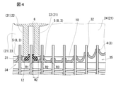
- the distance from the flat tube 32 to the joint portion becomes long, and the stress generated in the header plate 1 and the joint portion due to the thermal deformation of the flat tube 32 is dispersed throughout the burring 8. Therefore, by reducing the stress generated at the joint between the burring 8 of the end tube insertion hole 5 adjacent to the dummy tube insertion hole 6 and the flat tube 32, the thermal durability can be improved. Further, as in the comparative example of FIG. 4, when the burring 8 of the end tube insertion hole 5 adjacent to the dummy tube insertion hole 6 is formed larger than the burring 8 of the dummy tube insertion hole 6, the radius of curvature of the burring 8 is large.
- the root of the burring 8 of the end tube insertion hole 5 is closer to the side of the adjacent dummy tube insertion hole 6. Therefore, when the dummy tube insertion hole 6 has a normal burring height, it becomes difficult to secure a sufficient inter-tube sealing surface 12 on the bottom surface 10 of the header plate 1 between the dummy tube insertion hole 6 and the end tube insertion hole 5 adjacent thereto.
- the seal ring 31 rides on the burring 8 of the dummy tube insertion hole 6, and a sufficient sealing effect around the partition portion 22 of the tank body 21 cannot be expected.
- the height of the burring 8 of the dummy tube insertion hole 6 is formed so that the radius of curvature is lower than the height of the burring 8 of the end tube insertion hole 5 adjacent to the dummy tube insertion hole 6.
- the ratio of the height H1 of the burring 8 of the dummy tube insertion hole 6 to the height H2 of the burring 8 of the end tube insertion hole 5 is H2 / H1 ⁇ . It is set to 1.5.
- the stress applied to the joint portion of the header plate 1 is reduced to 1.5 times or more the height H1 of the burring 8 of the dummy tube insertion hole 6, the distance from the bottom surface 10 of the header plate 1 to the joint portion of the flat tube 32 is increased. It becomes longer and the stress reduction effect can be improved.
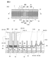
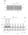
- FIG. 1 is a plan view and a cross-sectional view of a main part of the header plate 1 used in the header plate structure of the present invention.
- FIG. 2 is a plan view (A) of a main part showing the header plate structure of the present invention
- FIG. 2 (A) is an enlarged cross-sectional view taken along the line BB (B) of FIG. 2 (A).
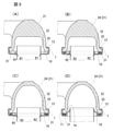
- FIG. 3 is a cross-sectional view taken along the line IIIA-IIIA (A), a cross-sectional view taken along the line IIIB-IIIB (B), a cross-sectional view taken along the line IIIC-IIIC (C), and a cross-sectional view taken along the line IIID-IIID (A).
- FIG. 1 is a plan view and a cross-sectional view of a main part of the header plate 1 used in the header plate structure of the present invention.
- FIG. 2 is a plan view (A) of a main part showing the header plate structure of the present invention
- FIG. 2 (A)
- FIG. 4 is an explanatory diagram showing a comparative example with the header plate structure of the present invention.
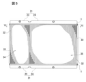
- FIG. 5 is a front view of a heat exchanger having a tank having a conventional header plate structure.
- 6 is a sectional view taken along the line VI-VI of FIG. 5 (A) and FIG. 6 (A) taken along the line BB.
- FIG. 7 is a cross-sectional view taken along the line VII-VII of FIG. 6 (A).
- this heat exchanger is suitable for use in a radiator or the like for cooling engine cooling water.
- the tank of this heat exchanger is composed of a tank body 21 and a header plate 1.
- the tank body 21 is made of a synthetic resin material and is formed in a box shape having an opening on the side connected to the header plate 1.
- a bottom is formed facing the opening.
- a small flange 25 that bulges toward the outside of the tank body 21 is formed on the edge of the opening.
- a pair of partition portions 22 are arranged inside the tank main body 21 so as to face each other with a distance of about one width in the lateral direction of the flat tube 32. As shown in FIG.
- the partition portion 22 is formed at an intermediate position in the longitudinal direction of the tank main body 21, and is formed from the bottom of the tank main body 21 toward the bottom surface 10 of the header plate 1. ..
- the ends of the partition 22 are connected to the bottom surface 10 of the header plate 1 via an annular seal ring 31, respectively.
- the inside of the tank body 21 is divided by a pair of partition portions 22, and a first tank portion 23 and a second tank portion 24 are formed on both sides of the pair of partition portions 22.
- the header plate 1 is a flat rectangular shape and is formed in an elongated shape. As shown in FIG.
- the bottom surface 10 of the header plate 1 has a plurality of flattened portions including a pair of opposite short side portions 2 and a pair of long side portions 3 connecting the two short side portions 2.
- Tube insertion hole 4 is formed.
- the short side portion 2 of the tube insertion hole 4 is located in the width direction of the header plate 1, and the tube insertion holes 4 are arranged apart from each other in the longitudinal direction of the header plate 1.
- the header plate 1 has a dummy tube insertion hole 6 (specifically, at a position corresponding to the position of the intermediate portion in the longitudinal direction of the header plate 1, specifically between the pair of partition portions 22 formed in the tank body 21. Similar to the tube insertion hole 4, a pair of short side portions 2 and a pair of long side portions 3) are formed.
- An end tube insertion hole 5 (consisting of a pair of short side portions 2 and a pair of long side portions 3 like the tube insertion hole 4) and a tube insertion hole 4 are provided on both sides of the dummy tube insertion hole 6 so as to sandwich the dummy tube insertion hole 6. They are arranged in parallel in order.
- the inner circumference of each tube insertion hole 4, the end tube insertion hole 5, and the dummy tube insertion hole 6 is the same.
- a burring 8 projecting inward of the tank body 21 is formed at the edge of each of the insertion holes 4, 5 and 6. The burring 8 is smoothly connected by a curved surface between the top 8a and the base 8b.
- a joining surface 9 formed on a flat surface so as to be easily joined to the flat tube 32.
- an outer peripheral wall that rises toward the tank body 21 is formed on the outer periphery of the header plate 1, and a claw portion 13 for caulking is formed at the tip portion thereof.
- a raised portion 14 is formed on the bottom surface 10 formed in the tube insertion hole 4 so as to be raised on the inner side of the tank body 21.
- the bottom surface 10 of the raised portion 14 is located higher than the bottom surface 10 formed in the dummy tube insertion hole 6 and the end tube insertion hole 5. As shown in FIGS.
- a groove 11 is formed between the outer peripheral edge of the bottom surface 10 of the raised portion 14 and the outer peripheral wall of the header plate 1.
- the rigidity of the region of the bottom 10 of the raised portion 14 is higher than the rigidity of the bottom 10 formed in the dummy tube insertion hole 6 and the end tube insertion hole 5.
- a large number of flat tubes 32 are arranged in parallel to form a core. The end of the flat tube 32 is inserted into each of the insertion holes 4, 5 and 6, and the flat tube 32 and the joint surface 9 of the burring 8 of each of the insertion portions 4, 5 and 6 are brazed and fixed.
- corrugated fins 33 can be arranged between the flat tubes 32.
- FIG. 2B corrugated fins 33 can be arranged between the flat tubes 32.
- the seal ring 31 is arranged on the groove 11 of the header plate 1 and the inter-tube sealing surface 12 between the dummy tube insertion hole 6 and the end tube insertion hole 5 adjacent thereto. ..
- the opening of the tank body 21 is fitted to the header plate 1 via the seal ring 31.
- the claw portion 13 of the header plate 1 is crimped to the small flange 25 side of the tank body 21, so that the tank body 21 and the header plate 1 are fixed.
- the pair of partition portions 22 have the tips of the partition portions 22 in contact with the seal ring 31 at the positions of the tube-to-tube sealing surfaces 12.
- the core is divided on both sides of the dummy tube insertion hole 6 in the longitudinal direction by the dummy tube insertion hole 6, the pair of partition portions 22 in the tank body 21, and the flat tube 32 inserted into the dummy tube insertion hole 6. Will be done.
- a first core 34 is arranged on the side of the first tank portion 23, a second core 35 is arranged on the side of the second tank portion 24, and different heat media can be circulated through the cores 34 and 35.
- engine cooling water can be circulated through the first core 34
- auxiliary cooling water can be circulated through the second core 35.
- thermal stress is generated between 35.
- thermal stress is likely to occur in the flat tube 32 located in the vicinity of the partition portion 22 of the tank body 21 which is the boundary between the cores 34 and 35.
- the region of the bottom 10 formed in the dummy tube insertion hole 6 and the end tube insertion hole 5 is raised because the rigidity of the peripheral portion of the insertion holes 5 and 6 is weakened with respect to the other rigidity.
- the portion 14 is not formed.
- a burring 8 having a height H1 from the bottom surface 10 of the header plate 1 to the top portion 8a of the burring 8 is formed on the long side portion 3 of the dummy tube insertion hole 6.
- the height H2 of the burring 8 of the end tube insertion hole 5 is formed higher than the height H1 of the burring 8 of the dummy tube insertion hole 6.
- the end tube insertion hole 5 disengaged from the position adjacent to the dummy tube insertion hole 6 has a long side portion 3 from the bottom surface 10 of the header plate 1 to the top portion 8a of the burring 8.
- a burring 8 having a height H3 can be formed.
- the height H3 may be formed to be lower than the height H2 and higher than the height H1.
- the thermal stress applied to the flat tube 32 of the end tube insertion hole 5 that deviates from the position adjacent to the dummy tube insertion hole 6 is higher than the thermal stress applied to the flat tube 32 of the end tube insertion hole 5 adjacent to the dummy tube insertion hole 6. Is also small, so height is not required so much.
- the burring 8 of the end tube insertion hole 5 adjacent to the dummy tube insertion hole 6 has a joint surface 9 formed in the vicinity of the top 8a of the burring 8 from the base 8b of the burring to the joint surface 9 with the flat tube 32. The distance becomes longer.
- the height H1 of the burring 8 of the dummy tube insertion hole 6 is tentatively about half the height H2 of the burring 8 of the end tube insertion hole 5 adjacent to the dummy tube insertion hole 6, that is, FIG. 1 (B).
- the root 8b of the burring 8 of the end tube insertion hole 5 adjacent to the dummy tube insertion hole 6 is closer to the adjacent dummy tube insertion hole 6 side. Therefore, when the height H1 of the dummy tube insertion hole 6 is set to be about the same as the burring height H3, the width W2 of the tube-to-tube sealing surface 12 becomes narrow, and it becomes difficult to secure a sufficient tube-to-tube sealing surface 12. That is, as shown in FIG. 4, the seal ring 31 rides on the burring 8 of the dummy tube insertion hole 6, and a sufficient sealing effect around the partition portion 22 of the tank body 21 cannot be expected. Therefore, as shown in FIGS.
- the height H1 of the burring 8 of the dummy tube insertion hole 6 is the height of the burring 8 of the end tube insertion hole 5 adjacent to the dummy tube insertion hole 6.
- the radius of curvature R1 of the burring 8 is made lower than the radius of curvature R2 of the burring 8 of the end tube insertion hole 5 adjacent to the dummy tube insertion hole 6, so that the burring 8 rises at the base 8b.
- the ratio of the height H1 of the burring 8 of the dummy tube insertion hole 6 to the height H2 of the burring 8 of the end tube insertion hole 5 is preferably a structure in the range of H2 / H1 ⁇ 1.5.
- the burring 8 of the end tube insertion hole 5 adjacent to the dummy tube insertion hole 6 is 1.5 times or more the height H1 of the burring 8 of the dummy tube insertion hole 6, the burring The distance from the base 8b of 8 to the joint surface 9 of the flat tube 32 becomes longer, and the stress reducing effect can be improved.
- the height of the short side connecting the long sides of the dummy tube insertion hole 6 and the end tube insertion hole 5 is the same as or lower than the height of the long side of the dummy tube insertion hole 6 and the end tube insertion hole 5. It is preferable to do so.
Landscapes
- Engineering & Computer Science (AREA)
- Physics & Mathematics (AREA)
- Thermal Sciences (AREA)
- Mechanical Engineering (AREA)
- General Engineering & Computer Science (AREA)
- Details Of Heat-Exchange And Heat-Transfer (AREA)
- Heat-Exchange Devices With Radiators And Conduit Assemblies (AREA)
Priority Applications (3)
| Application Number | Priority Date | Filing Date | Title |
|---|---|---|---|
| JP2022536470A JPWO2022014719A1 (enExample) | 2020-07-17 | 2021-07-09 | |
| US18/016,472 US12259201B2 (en) | 2020-07-17 | 2021-07-09 | Header plates structure of heat exchanger |
| CN202180038833.5A CN115667834A (zh) | 2020-07-17 | 2021-07-09 | 热交换器的集管板结构 |
Applications Claiming Priority (2)
| Application Number | Priority Date | Filing Date | Title |
|---|---|---|---|
| JP2020123296 | 2020-07-17 | ||
| JP2020-123296 | 2020-07-17 |
Publications (1)
| Publication Number | Publication Date |
|---|---|
| WO2022014719A1 true WO2022014719A1 (ja) | 2022-01-20 |
Family
ID=79554698
Family Applications (1)
| Application Number | Title | Priority Date | Filing Date |
|---|---|---|---|
| PCT/JP2021/026900 Ceased WO2022014719A1 (ja) | 2020-07-17 | 2021-07-09 | 熱交換器のヘッダプレート構造 |
Country Status (4)
| Country | Link |
|---|---|
| US (1) | US12259201B2 (enExample) |
| JP (1) | JPWO2022014719A1 (enExample) |
| CN (1) | CN115667834A (enExample) |
| WO (1) | WO2022014719A1 (enExample) |
Families Citing this family (2)
| Publication number | Priority date | Publication date | Assignee | Title |
|---|---|---|---|---|
| JP7445774B2 (ja) * | 2020-02-19 | 2024-03-07 | ハンオン システムズ | 熱応力を分散するための流量配分タンク構造を有する熱交換器 |
| DE102021211777A1 (de) * | 2021-10-19 | 2023-04-20 | Mahle International Gmbh | Wärmeübertrager zur wärmetechnischen Kopplung zweier Fluide |
Citations (4)
| Publication number | Priority date | Publication date | Assignee | Title |
|---|---|---|---|---|
| FR2785376A1 (fr) * | 1998-10-29 | 2000-05-05 | Valeo Thermique Moteur Sa | Echangeur de chaleur multifonction, notamment pour vehicule automobile |
| DE102007044742A1 (de) * | 2007-09-18 | 2009-04-23 | Behr Gmbh & Co. Kg | Wärmeübertrager insbesondere eines Kraftfahrzeuges mit einem Kühlmittelkasten für ein Kühlmittel |
| WO2010133491A1 (fr) * | 2009-05-18 | 2010-11-25 | Valeo Systemes Thermiques | Boîte collectrice pour échangeur de chaleur, en particulier à flux multiples |
| WO2020158364A1 (ja) * | 2019-02-01 | 2020-08-06 | 株式会社デンソー | 熱交換器 |
Family Cites Families (9)
| Publication number | Priority date | Publication date | Assignee | Title |
|---|---|---|---|---|
| DE2847525C3 (de) * | 1978-11-02 | 1981-04-02 | Ford-Werke AG, 5000 Köln | Wärmetauscher für Verdampfer, insbesondere für Klimaanlagen |
| JP3678130B2 (ja) | 2000-10-11 | 2005-08-03 | 株式会社デンソー | 熱交換器 |
| US7426958B2 (en) * | 2003-08-19 | 2008-09-23 | Visteon Global Technologies Inc. | Header for heat exchanger |
| JP5598565B2 (ja) * | 2013-04-19 | 2014-10-01 | 株式会社デンソー | 熱交換器 |
| JP6520681B2 (ja) * | 2015-12-10 | 2019-05-29 | 株式会社デンソー | 熱交換器 |
| JP2019085026A (ja) * | 2017-11-09 | 2019-06-06 | トヨタ自動車株式会社 | ラジエータ |
| US11029101B2 (en) * | 2019-02-11 | 2021-06-08 | Hanon Systems | Reverse header design for thermal cycle |
| US20220282938A1 (en) * | 2019-09-13 | 2022-09-08 | T.Rad Co., Ltd. | Tank structure of heat exchanger |
| WO2021054484A1 (ja) * | 2019-09-20 | 2021-03-25 | 株式会社ティラド | 熱交換器の偏平チューブとヘッダプレートのろう付構造 |
-
2021
- 2021-07-09 US US18/016,472 patent/US12259201B2/en active Active
- 2021-07-09 JP JP2022536470A patent/JPWO2022014719A1/ja active Pending
- 2021-07-09 CN CN202180038833.5A patent/CN115667834A/zh active Pending
- 2021-07-09 WO PCT/JP2021/026900 patent/WO2022014719A1/ja not_active Ceased
Patent Citations (4)
| Publication number | Priority date | Publication date | Assignee | Title |
|---|---|---|---|---|
| FR2785376A1 (fr) * | 1998-10-29 | 2000-05-05 | Valeo Thermique Moteur Sa | Echangeur de chaleur multifonction, notamment pour vehicule automobile |
| DE102007044742A1 (de) * | 2007-09-18 | 2009-04-23 | Behr Gmbh & Co. Kg | Wärmeübertrager insbesondere eines Kraftfahrzeuges mit einem Kühlmittelkasten für ein Kühlmittel |
| WO2010133491A1 (fr) * | 2009-05-18 | 2010-11-25 | Valeo Systemes Thermiques | Boîte collectrice pour échangeur de chaleur, en particulier à flux multiples |
| WO2020158364A1 (ja) * | 2019-02-01 | 2020-08-06 | 株式会社デンソー | 熱交換器 |
Also Published As
| Publication number | Publication date |
|---|---|
| US20230280112A1 (en) | 2023-09-07 |
| US12259201B2 (en) | 2025-03-25 |
| CN115667834A (zh) | 2023-01-31 |
| JPWO2022014719A1 (enExample) | 2022-01-20 |
Similar Documents
| Publication | Publication Date | Title |
|---|---|---|
| GB2433111A (en) | A stiffening part to reinforce tubes of a heat exchanger | |
| JPH0712489A (ja) | 多数の管の列を有する、特に自動車用の熱交換機 | |
| WO2017064940A1 (ja) | 熱交換器 | |
| JP2006189206A (ja) | 熱交換器 | |
| WO2022014719A1 (ja) | 熱交換器のヘッダプレート構造 | |
| US11835297B2 (en) | Heat exchanger | |
| CN114341580A (zh) | 热交换器的箱结构 | |
| CN210533100U (zh) | 具有改进的管加强装置的热交换器 | |
| KR102703322B1 (ko) | 열교환기 | |
| JP2006284107A (ja) | 熱交換器 | |
| WO2021054484A1 (ja) | 熱交換器の偏平チューブとヘッダプレートのろう付構造 | |
| WO2022071607A1 (ja) | 熱交換器のヘッダプレート構造 | |
| JP4664114B2 (ja) | 多板式熱交換器 | |
| JP7555776B2 (ja) | 熱交換器のヘッダプレート構造 | |
| JP2009150587A (ja) | 熱交換器 | |
| JPH09280774A (ja) | 熱交換器 | |
| JP5030677B2 (ja) | 熱交換器のタンク構造 | |
| JP2022060111A (ja) | 熱交換器のヘッダプレート構造 | |
| JP4448377B2 (ja) | プレート式熱交換器 | |
| JP5084735B2 (ja) | 熱交換器ヘッダタンクのための強化されたマニホルド、およびこのようなマニホルドを備えるヘッダタンク | |
| JP7511545B2 (ja) | 熱交換器用タンクのコアプレート | |
| JP2005249341A (ja) | 熱交換器 | |
| JPH0719784A (ja) | 熱交換器 | |
| KR101566546B1 (ko) | 루버 핀형 열교환기 | |
| JP2020003089A (ja) | 熱交換チューブ及び熱交換器 |
Legal Events
| Date | Code | Title | Description |
|---|---|---|---|
| 121 | Ep: the epo has been informed by wipo that ep was designated in this application |
Ref document number: 21843537 Country of ref document: EP Kind code of ref document: A1 |
|
| ENP | Entry into the national phase |
Ref document number: 2022536470 Country of ref document: JP Kind code of ref document: A |
|
| NENP | Non-entry into the national phase |
Ref country code: DE |
|
| 122 | Ep: pct application non-entry in european phase |
Ref document number: 21843537 Country of ref document: EP Kind code of ref document: A1 |
|
| WWG | Wipo information: grant in national office |
Ref document number: 18016472 Country of ref document: US |