WO2017064940A1 - 熱交換器 - Google Patents
熱交換器 Download PDFInfo
- Publication number
- WO2017064940A1 WO2017064940A1 PCT/JP2016/076079 JP2016076079W WO2017064940A1 WO 2017064940 A1 WO2017064940 A1 WO 2017064940A1 JP 2016076079 W JP2016076079 W JP 2016076079W WO 2017064940 A1 WO2017064940 A1 WO 2017064940A1
- Authority
- WO
- WIPO (PCT)
- Prior art keywords
- tube
- tubes
- core plate
- width direction
- wall portion
- Prior art date
Links
Images


Classifications
-
- F—MECHANICAL ENGINEERING; LIGHTING; HEATING; WEAPONS; BLASTING
- F28—HEAT EXCHANGE IN GENERAL
- F28F—DETAILS OF HEAT-EXCHANGE AND HEAT-TRANSFER APPARATUS, OF GENERAL APPLICATION
- F28F9/00—Casings; Header boxes; Auxiliary supports for elements; Auxiliary members within casings
- F28F9/02—Header boxes; End plates
- F28F9/0219—Arrangements for sealing end plates into casing or header box; Header box sub-elements
- F28F9/0224—Header boxes formed by sealing end plates into covers
- F28F9/0226—Header boxes formed by sealing end plates into covers with resilient gaskets
-
- F—MECHANICAL ENGINEERING; LIGHTING; HEATING; WEAPONS; BLASTING
- F28—HEAT EXCHANGE IN GENERAL
- F28D—HEAT-EXCHANGE APPARATUS, NOT PROVIDED FOR IN ANOTHER SUBCLASS, IN WHICH THE HEAT-EXCHANGE MEDIA DO NOT COME INTO DIRECT CONTACT
- F28D1/00—Heat-exchange apparatus having stationary conduit assemblies for one heat-exchange medium only, the media being in contact with different sides of the conduit wall, in which the other heat-exchange medium is a large body of fluid, e.g. domestic or motor car radiators
- F28D1/02—Heat-exchange apparatus having stationary conduit assemblies for one heat-exchange medium only, the media being in contact with different sides of the conduit wall, in which the other heat-exchange medium is a large body of fluid, e.g. domestic or motor car radiators with heat-exchange conduits immersed in the body of fluid
- F28D1/04—Heat-exchange apparatus having stationary conduit assemblies for one heat-exchange medium only, the media being in contact with different sides of the conduit wall, in which the other heat-exchange medium is a large body of fluid, e.g. domestic or motor car radiators with heat-exchange conduits immersed in the body of fluid with tubular conduits
- F28D1/053—Heat-exchange apparatus having stationary conduit assemblies for one heat-exchange medium only, the media being in contact with different sides of the conduit wall, in which the other heat-exchange medium is a large body of fluid, e.g. domestic or motor car radiators with heat-exchange conduits immersed in the body of fluid with tubular conduits the conduits being straight
- F28D1/0535—Heat-exchange apparatus having stationary conduit assemblies for one heat-exchange medium only, the media being in contact with different sides of the conduit wall, in which the other heat-exchange medium is a large body of fluid, e.g. domestic or motor car radiators with heat-exchange conduits immersed in the body of fluid with tubular conduits the conduits being straight the conduits having a non-circular cross-section
- F28D1/05366—Assemblies of conduits connected to common headers, e.g. core type radiators
-
- F—MECHANICAL ENGINEERING; LIGHTING; HEATING; WEAPONS; BLASTING
- F28—HEAT EXCHANGE IN GENERAL
- F28F—DETAILS OF HEAT-EXCHANGE AND HEAT-TRANSFER APPARATUS, OF GENERAL APPLICATION
- F28F9/00—Casings; Header boxes; Auxiliary supports for elements; Auxiliary members within casings
- F28F9/02—Header boxes; End plates
- F28F9/04—Arrangements for sealing elements into header boxes or end plates
- F28F9/16—Arrangements for sealing elements into header boxes or end plates by permanent joints, e.g. by rolling
- F28F9/18—Arrangements for sealing elements into header boxes or end plates by permanent joints, e.g. by rolling by welding
- F28F9/182—Arrangements for sealing elements into header boxes or end plates by permanent joints, e.g. by rolling by welding the heat-exchange conduits having ends with a particular shape, e.g. deformed; the heat-exchange conduits or end plates having supplementary joining means, e.g. abutments
-
- F—MECHANICAL ENGINEERING; LIGHTING; HEATING; WEAPONS; BLASTING
- F28—HEAT EXCHANGE IN GENERAL
- F28F—DETAILS OF HEAT-EXCHANGE AND HEAT-TRANSFER APPARATUS, OF GENERAL APPLICATION
- F28F2225/00—Reinforcing means
- F28F2225/02—Reinforcing means for casings
-
- F—MECHANICAL ENGINEERING; LIGHTING; HEATING; WEAPONS; BLASTING
- F28—HEAT EXCHANGE IN GENERAL
- F28F—DETAILS OF HEAT-EXCHANGE AND HEAT-TRANSFER APPARATUS, OF GENERAL APPLICATION
- F28F2225/00—Reinforcing means
- F28F2225/08—Reinforcing means for header boxes
-
- F—MECHANICAL ENGINEERING; LIGHTING; HEATING; WEAPONS; BLASTING
- F28—HEAT EXCHANGE IN GENERAL
- F28F—DETAILS OF HEAT-EXCHANGE AND HEAT-TRANSFER APPARATUS, OF GENERAL APPLICATION
- F28F2265/00—Safety or protection arrangements; Arrangements for preventing malfunction
- F28F2265/26—Safety or protection arrangements; Arrangements for preventing malfunction for allowing differential expansion between elements
Definitions
- This disclosure relates to a heat exchanger.
- a heat exchanger such as a radiator includes a core portion in which a plurality of tubes and a plurality of corrugated fins are alternately stacked, a header tank that is joined to the longitudinal ends of the plurality of tubes and communicates with the plurality of tubes.
- the header tank includes a core plate into which a plurality of tubes are inserted and joined, and a tank body that forms an internal space of the header tank together with the core plate.
- the core plate includes a tube joint surface provided with a plurality of tube insertion holes, and a receiving portion that is provided on the outer peripheral edge of the tube joint surface and receives the end of the tank main body.
- This indication aims at providing the heat exchanger which can shorten the length of the width direction, and can reduce the thermal stress in the joined part of a core plate and a plurality of tubes in view of the above-mentioned point. To do.
- the heat exchanger includes a plurality of flat tubes arranged in a stacked manner, and a header tank that is disposed at the longitudinal ends of the plurality of tubes and communicates with the plurality of tubes.
- the header tank has a core plate to which the longitudinal ends of a plurality of tubes are joined, and a tank main body fixed to the core plate.
- the core plate has a tube joint surface and a receiving part.
- the tube joint surface is provided with a plurality of tube insertion holes corresponding to the plurality of tubes, and the plurality of tubes are brazed and joined in a state of being inserted into the plurality of tube insertion holes, respectively.
- the receiving portion surrounds the tube joint surface and accommodates a tip portion close to the core plate in the tank main body portion.
- the receiving part has a bottom wall part in which a sealing member is disposed between the tank body part and an inner wall part that connects the tube joining surface and the bottom wall part.
- a rib that is inclined with respect to the longitudinal direction of the plurality of tubes is provided between two adjacent ones of the plurality of tube insertion holes on the tube joining surface and the inner wall portion.
- One end side of the rib is connected to the tube joining surface and the other end side is connected to the inner wall portion in the width direction of the plurality of tubes.
- the other end portion of the rib is connected in the middle of the inner wall portion in the longitudinal direction of the plurality of tubes.
- the core plate in the width direction (tube width direction) of the plurality of tubes in which stress is concentrated It is possible to suppress bending deformation in the vicinity of the joint portion of the plurality of tubes with the end portions in the tube width direction, and to distribute stress to the tip portions of the ribs.
- ribs that extend continuously in the tube width direction (tube width direction) are formed on the tube joint surface without being connected diagonally, the rigidity of the entire tube width direction of the core plate increases.
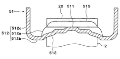
- FIG. 5 is a sectional view taken along line VV in FIG. 4.
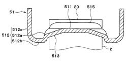
- FIG. 5 is a sectional view taken along line VI-VI in FIG. 4.
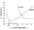
- the heat exchanger of embodiment and a 1st comparative example it is a graph which shows the relationship between the distance of a tube joint surface and the receiving part of a core plate, and a thermal stress.
- FIG. 13 is a cross-sectional view taken along line XIII-XIII in FIG. 12. It is a graph which shows the stress which arises in the radiator of embodiment and a 2nd comparative example.
- the heat exchanger according to the present disclosure is effective when applied to a vehicle heat exchanger mounted on a vehicle.
- This embodiment demonstrates the example which applied the heat exchanger which concerns on this indication to the radiator 1 which cools the water-cooling type internal combustion engine which is mounted in the vehicle which is not shown in figure.
- the radiator 1 of the present embodiment has a core portion 4 that is a heat exchange portion for exchanging heat between the cooling water of the internal combustion engine and the outside air.
- the core part 4 is a laminated body in which a plurality of tubes 2 and a plurality of fins 3 are arranged in a plurality of layers in the vertical direction.
- the tube 2 and the fin 3 it refers to one of the plurality of tubes 2 and one of the plurality of fins 3.
- each of the plurality of tubes 2 other than the one tube 2 has the same structure as the one tube 2, and the plurality of fins 3 other than the one fin 3 are the same as the one fin 3, respectively. It has the same structure.
- Each of the plurality of tubes 2 is a tubular member in which a flow path through which cooling water of an internal combustion engine (not shown) flows is formed.
- the plurality of tubes 2 extend so that the longitudinal direction of the plurality of tubes is along the horizontal direction.
- the plurality of tubes 2 extend so that the major axis direction of the cross section orthogonal to the longitudinal direction is along the flow direction of the air passing through the core portion 4, and have a flat shape.
- the flat shape includes an elliptical shape including a curved shape obtained by combining an arc portion having a large radius of curvature and an arc portion having a small radius of curvature, an oval shape including a shape obtained by combining the arc portion and a flat portion, and the like. .
- the major axis direction of the tube 2 is referred to as a tube width direction, and the direction in which the tube 2 extends (longitudinal direction) is referred to as a tube longitudinal direction.
- a direction in which the plurality of tubes 2 and the plurality of fins 3 are stacked is referred to as a tube stacking direction.
- the tube width direction coincides with a direction orthogonal to both the tube longitudinal direction and the tube stacking direction.
- the fins 3 increase the heat transfer area with the outside air and promote heat exchange between the outside air and the cooling water.
- the fins 3 of the present embodiment are formed in a corrugated shape and are joined to flat portions on both sides of the tube 2.
- the tube 2 and the fin 3 are made of a metal (for example, an aluminum alloy) having excellent thermal conductivity, corrosion resistance, and the like.
- the tube 2, the fin 3, the core plate 51 described later, and the side plate 6 described later are integrally brazed by a brazing material that is coated at predetermined positions of the tube 2, the fin 3, the core plate 51, and the side plate 6. .
- header tanks 5 extending in the tube stacking direction and having spaces formed therein are disposed.
- the header tank 5 includes a core plate 51 into which a plurality of tubes 2 are inserted and joined, and a tank body 52 that forms a tank space together with the core plate 51.
- the header tank 5 is joined in a state in which the end portions in the tube longitudinal direction of each of the plurality of tubes 2 are inserted into a plurality of tube insertion holes 511 a described later of the core plate 51.
- the internal passages of the plurality of tubes 2 communicate with a space formed in the header tank 5.
- Side plates 6 that reinforce the core portion 4 are provided at both ends of the core portion 4 in the tube stacking direction.
- the side plate 6 extends in parallel with the tube longitudinal direction, and both ends thereof are connected to the core plate 51.
- the side plate 6 of the present embodiment is made of a metal such as an aluminum alloy.
- the header tank 5 includes a core plate 51, a tank body 52, and a packing 53.
- the core plate 51 is joined in a state where the plurality of tubes 2 and the side plates 6 are inserted.
- the tank body 52 and the core plate 51 constitute a tank internal space that is a space in the header tank 5.
- the packing 53 is a seal member that seals between the core plate 51 and the tank main body 52.
- the core plate 51 of the present embodiment is made of a metal (for example, an aluminum alloy) excellent in thermal conductivity, corrosion resistance, and the like.
- the tank body 52 of this embodiment is formed of a resin such as glass reinforced polyamide reinforced with glass fibers.
- the packing 53 is made of, for example, silicon rubber or EPDM (ethylene propylene diene rubber).
- the core plate 51 is provided with a plurality of protruding pieces 514.
- Each of the plurality of protruding pieces 514 is formed so as to protrude from the outer wall portion 512c to the tank body portion 52 side.
- the plurality of projecting pieces 514 are provided at a portion corresponding to a space between two adjacent tubes 2 among the plurality of tubes 2 in the core plate 51, that is, a portion corresponding to the flange portion (tip portion) 522 of the tank main body portion 52. Has been placed.
- the plurality of protruding pieces 514 of the core plate 51 are plastically deformed so as to press against the tank main body 52.
- the core plate 51 is fixed by caulking.
- the tank body 52 is assembled to the core plate 51 by caulking and fixing the plurality of protruding pieces 514 to the flange 522 of the tank body 52.
- the inner surface of the tank main body 52 is located on the inner side of the tank 5, that is, closer to the center of the tube 2 in the tube width direction than the end of the tube 2 in the tube width direction.
- the inner surface of the tank body 52 is located between the end of the tube 2 and the center of the tube 2 in the tube width direction.
- a concave portion 521 that is recessed toward the outer side of the tank is formed in a portion of the tank main body 52 that faces the tube 2. Thereby, it is comprised so that the inner surface of the tank main-body part 52 and the outer surface of the said edge part of the tube 2 may not contact.
- the flange portion 522 is disposed on a bottom wall portion 512b (described later) of the core plate 51 via a packing 53. That is, the bottom wall portion 512b constitutes a seal surface on which the packing 53 is disposed.
- the direction perpendicular to both the tube stacking direction and the tube width direction is the tube longitudinal direction.
- the direction perpendicular to both the tube width direction and the tube longitudinal direction is the tube stacking direction. 3, 5, and 6, illustration of the plurality of protruding pieces 514 is omitted.
- the core plate 51 is formed with a tube joint surface 511 to be joined in a state where a plurality of tubes 2 are inserted.
- the tube joint surface 511 is formed in a flat shape.
- the tube joining surface 511 is formed so as to intersect the tube longitudinal direction and extend in the tube width direction.
- the tube joint surface 511 of the present embodiment is formed orthogonal to the tube longitudinal direction and parallel to the tube width direction.
- the tube joint surface 511 has a plurality of tube insertion holes 511a.
- the plurality of tube insertion holes 511a are formed so as to be arranged at predetermined intervals along the tube stacking direction.
- the tube insertion hole 511a is brazed and joined in a state where the end portion in the longitudinal direction of the tube 2 (hereinafter referred to as the tube end portion 20) is inserted.
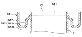
- a groove-shaped receiving part (accommodating receiving part) 512 is formed around the tube joint surface 511 in the core plate 51.
- the receiving part 512 accommodates a flange part 522 and a packing 53 of the tank main body part 52 described later.
- the receiving portion 512 has three wall surfaces including a bottom wall portion 512b extending in the tube width direction, an inner wall portion 512a and an outer wall portion 512c extending in the tube longitudinal direction. These wall surfaces are formed in this order from the tube joint surface 511 to the inner wall portion 512a, the bottom wall portion 512b, and the outer wall portion 512c.
- the inner wall portion 512a and the outer wall portion 512c are each formed by being bent into an L shape from the bottom wall portion 512b.
- the inner wall portion 512a is located closer to the tube 2 than the bottom wall portion 512b, and the outer wall portion 512c is located farther from the tube 2 than the bottom wall portion 512b.
- the inner wall portion 512a is located between the bottom wall portion 512b and the tube 2 in the tube width direction, and the bottom wall portion 512b is located between the outer wall portion 512c and the tube 2 in the tube width direction. Is located.
- the inner wall portion 512a is disposed outside the tube 2 in the tube width direction. That is, the entire receiving portion 512 of the core plate 51 is disposed outside the tube 2 in the tube width direction.
- a gap of a predetermined distance L is formed between the inner wall portion 512a and the end portion of the tube 2 in the tube width direction.
- the end of the tube 2 in the tube width direction has an arc shape in a cross section viewed from the tube longitudinal direction.
- the predetermined distance L in the present embodiment is the shortest distance in the tube width direction between the 0 ° position and the inner wall portion 512a. .
- the end of the tube 2 in the tube width direction is located on a flat surface that constitutes the tube joint surface 511.
- the core plate 51 extends in parallel with the tube width direction at a portion where the end of the tube 2 in the tube width direction and the core plate 51 are joined.
- the distance in the tube longitudinal direction between the tube joining surface 511 and the tube end portion 20 is different from the distance in the tube longitudinal direction between the bottom wall portion 512b and the tube end portion 20.
- the distance from the tube joining surface 511 to the tube end portion 20 is shorter than the distance from the bottom wall portion 512b to the tube end portion 20. That is, the bottom wall portion 512b is disposed on the side closer to the core portion 4 in the tube longitudinal direction than the tube joining surface 511, that is, on the side farther from the tube end portion 20.
- the tube joint surface 511 is located between the bottom wall portion 512b and the tube end portion 20 in the tube longitudinal direction.
- Ribs 513 are provided on the tube joint surface 511 and the inner wall portion 512a of the core plate 51 between two adjacent tubes 2, that is, between two adjacent tube insertion holes 511a.
- the rib 513 is formed so as to protrude from the plate surface of the core plate 51.
- the rib 513 of the present embodiment is formed so as to protrude toward the core portion 4 in the tube longitudinal direction, that is, in a direction away from the tube end portion 20.
- the rib 513 is provided to increase the rigidity of the core plate 51.
- the rib 513 is inclined with respect to the tube longitudinal direction.
- the rib 513 is inclined with respect to the tube joint surface 511, that is, with respect to the tube width direction.
- the rib 513 is inclined so that the distance from the tube end portion 20 becomes longer in the direction from the tube joint surface 511 toward the receiving portion 512, that is, in the direction away from the center portion in the tube width direction.
- the rib 513 is formed from the tube joint surface 511 to the inner wall portion 512a in the tube width direction. That is, in the tube width direction, one end of the rib 513 is connected to the tube joint surface 511, and the other end of the rib 513 is connected to the inner wall portion 512a.
- One end of the rib 513 is, for example, an end portion on the side close to the center portion in the tube width direction of the tube 2.
- the other end of the rib 513 is, for example, an end portion on the side far from the center portion of the tube 2 in the tube width direction.
- the rib 513 is formed so as to straddle the end of the tube 2 in the tube width direction as viewed from the tube stacking direction.
- the other end of the rib 513 is connected to the middle of the inner wall portion 512a in the tube longitudinal direction.
- the other end of the rib 513 is located between one end and the other end of the inner wall portion 512a in the tube longitudinal direction in the tube longitudinal direction.
- the other end of the rib 513 is located between a connection portion between the inner wall portion 512a and the tube joint surface 511 and a connection portion between the inner wall portion 512a and the bottom wall portion 512b.
- the other end of the rib 513 is located farther from the tube end portion 20 than the tube joining surface 511 and closer to the tube end portion 20 than the bottom wall portion 512b in the tube longitudinal direction.
- the other end of the rib 513 is located on the opposite side of the tube end portion 20 with respect to the tube joint surface 511 in the longitudinal direction, and is located between the bottom wall portion 512b and the tube end portion 20 in the longitudinal direction. is doing.
- the burring part 515 which protrudes toward the internal space of the header tank 5 is formed in the site
- the burring portion 515 is provided to increase the rigidity of the peripheral edge portion of the tube insertion hole 511a in the core plate 51.
- This preparation step includes a step of forming the core plate 51 having the tube joint surface 511, the receiving portion 512, the protruding piece 514, and the rib 513.
- the tube insertion hole 511a is formed on the flat surface of the tube joint surface 511 by punching a plate-shaped metal material (that is, punching).
- a temporary assembly process for temporarily assembling the core portion 4 and the like is performed by assembling the tubes 2, fins 3, and side plates 6 prepared in the preparation process on the workbench in the tube stacking direction.
- the core plate 51 in which the tube insertion hole 511a is formed is assembled to the core portion 4, the state of being assembled by a jig such as a wire is held.
- the assembly in a state where the core plate 51 is assembled to the core part 4 is placed in a heated furnace, thereby performing a brazing joining process for joining the elements of the core plate 51 and the core part 4 by brazing.
- the packing 53 is accommodated in the receiving portion 512 of the core plate 51. Then, in a state where the flange portion 522 of the tank main body portion 52 is accommodated in the receiving portion 512 of the core plate 51 in which the packing 53 is accommodated, the projecting pieces 514 of the core plate 51 are plastically deformed by press working or the like. A caulking fixing process for caulking and fixing the tank body 52 to the plate 51 is performed.
- the radiator 1 is manufactured after leak inspection and dimensional inspection. In the leakage inspection or the like, it is confirmed whether or not there is a brazing defect or a caulking defect at a joint portion of each part of the radiator 1.
- the rib 513 of the core plate 51 is inclined with respect to the tube width direction, one end of the rib 513 is connected to the tube joint surface 511, and the other end of the rib 513 is the inner wall. It is connected in the middle of the part 512a.
- the vicinity of the joint portion hereinafter also referred to as a tube root portion
- Bending deformation is suppressed and stress can be distributed to the tip of the rib 513.
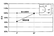
- the relationship between the predetermined distance L between the receiving portion 512 of the core plate 51 and the tube 2 (hereinafter simply referred to as the distance L) and the stress generated at the joint between the core plate 51 and the tube 2 will be described with reference to FIG. I will explain.
- the structure which provided the rib 513 in the flat surface which comprises the tube joint surface 511 of the core plate 51 is made into the 1st comparative example.
- the rib 513 of the first comparative example is formed in parallel with the tube width direction.
- the radiator 1 of this embodiment when the distance L is reduced, the tube root portion and the tip portion of the rib 513 are close to each other, and stress can be efficiently distributed to the tip portion of the rib 513.
- the inner wall part 512a can be made to adjoin to the tube 2, and the tube width direction dimension of the radiator 1 is made small. be able to.
- the inner surface of the tank main body portion 52 is located between the end portion and the center portion of the tube 2 in the tube width direction.
- the distance L is too large, the distance between the tube root portion and the tip portion of the rib 513 is increased, so that the stress reduction effect is lowered.
- the distance L is too small, the fillet shape when the tube 2 and the core plate 51 are brazed will not be stable, and the shape of the core plate 51 will not be stable because it requires press working within a narrow clearance. Therefore, even when the distance L is too small, the stress reduction effect is reduced.
- the optimum range of the distance L can obtain a stress reduction effect at the tube root, can stabilize the fillet shape of the tube root, and can process the core plate 51. It is determined as a range that can be stably executed.
- the optimum range of the distance L is set to a range larger than 0.43 mm and smaller than 1.30 mm (0.43 ⁇ L ⁇ 1.30). As shown in FIG. 7, when the distance L is 0.43 mm and 1.30 mm, the stress at the tube root is 100%.
- the core plate 51 may be deformed like a bow.
- the rib 513 is connected to a portion (connecting portion A) between one end and the other end in the tube longitudinal direction of the inner wall portion 512a, so that the rib 513 and the inner wall portion 512a Therefore, the core plate 51 is not easily deformed. Thereby, even if it is a case where the tube 2 is extended in the tube longitudinal direction, it becomes difficult to open the several protrusion piece 514 fixed by crimping.
- the core plate 51 is not inclined with respect to the tube width direction at the joint portion between the tube 2 and the core plate 51. That is, in the tube root portion, the core plate 51 is parallel to the tube width direction. For this reason, when the tube 2 and the core plate 51 are brazed, the fillet shape of the tube root portion can be stabilized.
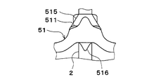
- the fillet 516 is formed only in the vicinity of the joint portion with the core plate 51 at the end of the tube 2 in the tube width direction.
- the height difference of the fillet 516 can be formed uniformly.
- stress can be disperse
- the portion of the core plate 51 to be joined to the end portion in the tube width direction of the tube 2 may have a shape as shown in FIGS.
- the shapes shown in FIGS. 15 to 17 can be realized when the tube insertion hole 511a is formed in the tube joint surface 511 of the core plate 51 by punching.
- the thickness of the core plate 51 is made uniform as a whole.
- the thickness of the core plate 51 may be made thinner than other portions.
- the thickness of the core plate 51 gradually decreases toward the tube joint surface 511 at the joint between the end of the tube 2 in the tube width direction and the core plate 51.
- a step is provided at the joint portion between the end of the tube 2 in the tube width direction and the core plate 51 so that the thickness of the core plate 51 changes stepwise.
- the said embodiment demonstrated the example in which the core plate 51 was parallel to the tube width direction in the junction part of the tube width direction end part in the tube 2, and the core plate 51, as shown in FIG.
- the core plate 51 may be gently inclined with respect to the tube width direction at the joint between the tube width direction end of the tube 2 and the core plate 51.
- 17 has an advantage that the tube 2 can be easily inserted into the tube insertion hole 511a of the core plate 51.
- the rib 513 of the core plate 51 may have a shape as shown in FIGS.
- a step may be provided in the middle of the rib 513 as shown in FIG.
- a plurality of steps may be provided.
- the length of the rib 513 in the tube width direction may be shortened.
- the connecting portion between the rib 513 and the inner wall portion 512a may be provided in a direction away from the bottom wall portion 512b in the tube longitudinal direction. That is, the inclination angle of the rib 513 with respect to the tube width direction may be smaller than that in the above embodiment.
- the structure of the packing 53 is not limited to this.
- the packing 53 may be joined or integrally molded to either one of the core plate 51 and the tank body 52 with an adhesive or the like.
Abstract
熱交換器は、複数のチューブ(2)と複数のチューブに連通するヘッダタンク(5)を備える。ヘッダタンクは、コアプレート(51)とタンク本体部(52)を有している。コアプレートは、チューブ接合面(511)と受部(512)を有している。チューブ接合面には複数のチューブ挿入穴(511a)が設けられている。受部は、タンク本体部の先端部(522)を収容する。受部は、底壁部(512b)と、チューブ接合面と底壁部とを接続する内側壁部(512a)を有している。チューブ接合面および内側壁部には、複数のチューブ挿入穴のうちの隣接する2つの間に、複数のチューブの長手方向に対して傾斜しているリブ(513)が設けられている。リブは、複数のチューブの幅方向において、一端側がチューブ接合面に接続され、他端側が内側壁部に接続されている。リブの他端部は、複数のチューブの長手方向において内側壁部の途中に接続されている。
Description
本出願は、当該開示内容が参照によって本出願に組み込まれた、2015年10月15日に出願された日本特許出願2015-203907号を基にしている。
本開示は、熱交換器に関するものである。
ラジエータ等の熱交換器は、複数のチューブと複数のコルゲートフィンとが交互に積層されたコア部、複数のチューブの長手方向端部に接合されて複数のチューブに連通するヘッダタンク等を備えている。ヘッダタンクは、複数のチューブが挿入接合されるコアプレートと、コアプレートとともにヘッダタンクの内部空間を形成するタンク本体部を備えている。コアプレートは、複数のチューブ挿入穴が設けられたチューブ接合面と、チューブ接合面の外周縁部に設けられ、タンク本体部の端部を受け入れる受部とを備えている。この種の熱交換器では、複数のチューブ内を流れる冷却水の流量分布と外気冷却風により複数のチューブのうち隣り合うチューブの間に温度差が生じた場合に、コアプレートのチューブ接合面が変形し、複数のチューブの幅方向の端部付近に応力が集中する。
これに対し、コアプレートにおける複数のチューブの幅方向の端部付近にリブを設けることが提案されている(例えば、特許文献1参照)。特許文献1に記載の熱交換器では、チューブ接合面に設けられたリブによって、コアプレートにおける複数のチューブの幅方向の端部付近での変形を抑え、複数のチューブの幅方向の端部付近で発生する応力をリブ先端部に分散させ低減する。
しかしながら、上記特許文献1に記載の熱交換器では、複数のチューブとコアプレートの受部との間隔が小さくなると、コアプレートのチューブ接合面において、リブ先端部で応力を分散させるために充分なスペースを確保できず、コアプレートと複数のチューブとの接合部で発生する応力は急増加する傾向がある。このため、熱交換器の幅方向寸法の低減と、コアプレートと複数のチューブの接合部での応力の低減を両立させることが困難であった。
本開示は上記点に鑑みて、幅方向の長さを短くし、かつ、コアプレートと複数のチューブとの接合部における熱応力を低減させることが可能な熱交換器を提供することを目的とする。
本開示の熱交換器は、積層配置された扁平形状の複数のチューブと、複数のチューブの長手方向端部に配置され、複数のチューブに連通するヘッダタンクと、を備える。ヘッダタンクは、複数のチューブの長手方向端部が接合されるコアプレートと、コアプレートに固定されるタンク本体部と、を有している。コアプレートは、チューブ接合面と受部を有している。チューブ接合面には、複数のチューブに対応する複数のチューブ挿入穴が設けられ、複数のチューブが複数のチューブ挿入穴にそれぞれ挿入された状態でろう付け接合されている。受部は、チューブ接合面を囲むとともに、タンク本体部におけるコアプレートに近接する先端部を収容する。受部は、タンク本体部との間にシール部材が配置される底壁部と、チューブ接合面と底壁部とを接続する内側壁部を有している。チューブ接合面および内側壁部には、複数のチューブ挿入穴のうちの隣接する2つの間に、複数のチューブの長手方向に対して傾斜しているリブが設けられている。リブは、複数のチューブの幅方向において、一端側がチューブ接合面に接続され、他端側が内側壁部に接続されている。リブの他端部は、複数のチューブの長手方向において、内側壁部の途中に接続されている。
これによれば、受部の内側壁部に、当該内側壁部に対して傾斜するようにリブを接続することで、応力が集中する複数のチューブの幅方向(チューブ幅方向)におけるコアプレートと複数のチューブのチューブ幅方向の端部との接合部付近での屈曲変形を抑制し、リブの先端部へ応力分散が可能となる。一方、斜めに接続されず、チューブ接合面に複数のチューブの幅方向(チューブ幅方向)に連続的に延びるリブが形成された場合には、コアプレートのチューブ幅方向全体の剛性が上がるためチューブ長手方向へ変形しにくくなり、前述のチューブ幅方向の端部の応力低減効果が低下し、チューブ幅方向全域に応力が発生してしまう問題がある。そのため、リブの一端側を、チューブ接合面の途中に接続させることで、コアプレートの剛性増加を抑えながら、チューブとコアプレートの接合部の、チューブ幅方向の端部近傍の部位の屈曲変形を抑制し、チューブとコアプレートの接合部の、チューブ幅方向の端部となる部位での応力集中を低減する効果が発揮できる。また、コアプレートの受部とチューブとの距離が小さくなると、コアプレートとチューブのチューブ幅方向の端部との接合部とリブの先端部が近くなり、効率的にリブの先端部へ応力分散が可能となる。これにより、内側壁部をチューブに近接させることができ、熱交換器の幅方向寸法を小さくすることができる。
本開示についての上記目的およびその他の目的、特徴や利点は、添付の図面を参照しながら下記の詳細な記述により、より明確になる。
実施形態に係るラジエータを示す模式的な正面図である。
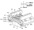
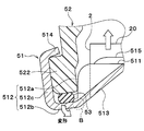
ラジエータのヘッダタンク近傍を示す分解斜視図である。
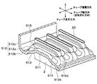
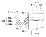
ラジエータのコアプレート近傍を示す分解斜視図である。
ラジエータのコアプレート単体の下面図である。
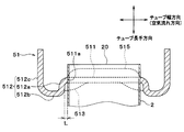
図4のV-V線における断面図である。
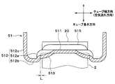
図4のVI-VI線における断面図である。
実施形態と第1比較例の熱交換器において、チューブ接合面とコアプレートの受部との距離と、熱応力との関係を示すグラフである。
実施形態のコアプレートの変形状態を示す断面図である。
第2比較例のコアプレートの変形状態を示す断面図である。
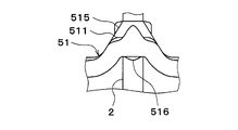
実施形態のチューブとコアプレートの接合部におけるフィレット形状を示す断面図である。
図10のXI-XI線における断面図である。
第2比較例のチューブとコアプレートの接合部におけるフィレット形状を示す断面図である。
図12のXIII-XIII線における断面図である。
実施形態および第2比較例のラジエータに生じる応力を示すグラフである。
コアプレートにおけるチューブ端部との接合部の変形例を示す断面図である。
コアプレートにおけるチューブ端部との接合部の変形例を示す断面図である。
コアプレートにおけるチューブ端部との接合部の変形例を示す断面図である。
コアプレートにおけるリブの変形例を示す断面図である。
コアプレートにおけるリブの変形例を示す断面図である。
コアプレートにおけるリブの変形例を示す断面図である。
本開示の一実施形態について図面に基づいて説明する。本開示に係る熱交換器は、車両に搭載される車両用の熱交換器に適用して有効である。本実施形態では、本開示に係る熱交換器を、車両に搭載された図示しない水冷式の内燃機関を冷却するラジエータ1に適用した例について説明する。
図1に示すように、本実施形態のラジエータ1は、内燃機関の冷却水を外気と熱交換させる熱交換部であるコア部4を有している。コア部4は、複数のチューブ2と複数のフィン3とが上下方向に複数層配置された積層体となっている。以下、単にチューブ2およびフィン3と称した場合、複数のチューブ2のうちの1つ、および複数のフィン3のうちの1つを指す。本実施形態では、当該1つのチューブ2以外の複数のチューブ2はそれぞれ当該1つのチューブ2と同様の構造を有し、当該1つのフィン3以外の複数のフィン3はそれぞれ当該1つのフィン3と同様の構造を有している。
複数のチューブ2はそれぞれ、その内部に図示しない内燃機関の冷却水が流通する流路が形成された管状部材である。複数のチューブ2は、複数のチューブの長手方向が水平方向に沿うように延びている。複数のチューブ2は、長手方向に直交する断面の長径方向がコア部4を通過する空気の流れ方向に沿うように延びており、扁平形状を有している。扁平形状は、曲率半径の大きい円弧部と曲率半径の小さい円弧部とを結合した曲線形状からなる楕円形状や、円弧部と平坦部とを結合した形状からなる長円形状等を包含している。
以下、チューブ2の長径方向をチューブ幅方向と称し、チューブ2が伸びる方向(長手方向)をチューブ長手方向と称する。また、複数のチューブ2と複数のフィン3が積層される方向を、チューブ積層方向と称する。本実施形態では、チューブ幅方向は、チューブ長手方向およびチューブ積層方向の双方に直交する方向と一致している。
フィン3は、外気との伝熱面積を増大させて、外気と冷却水との熱交換を促進する。本実施形態のフィン3は、コルゲート状に成形されており、チューブ2の両側の平坦部に接合されている。
チューブ2およびフィン3は、熱伝導率や耐食性等に優れた金属(例えば、アルミニウム合金)で構成されている。チューブ2、フィン3、後述するコアプレート51、後述するサイドプレート6は、チューブ2、フィン3、コアプレート51、サイドプレート6それぞれの所定箇所に被覆されたろう材によって一体的にろう付けされている。
複数のチューブ2それぞれのチューブ長手方向の両端部には、チューブ積層方向に延びるとともに、内部に空間が形成されたヘッダタンク5が配置されている。ヘッダタンク5は、複数のチューブ2が挿入接合されるコアプレート51と、コアプレート51とともにタンク空間を構成するタンク本体部52とを有している。ヘッダタンク5は、複数のチューブ2それぞれのチューブ長手方向の端部が、コアプレート51の後述する複数のチューブ挿入穴511aに挿入された状態で接合されている。複数のチューブ2それぞれの内部通路は、ヘッダタンク5の内部に形成される空間に連通している。
コア部4におけるチューブ積層方向の両端部には、コア部4を補強するサイドプレート6が設けられている。サイドプレート6は、チューブ長手方向と平行に延びてその両端部がコアプレート51に接続されている。本実施形態のサイドプレート6は、アルミニウム合金等の金属で構成されている。
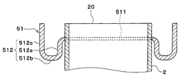
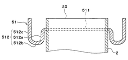
図2に示すように、ヘッダタンク5は、コアプレート51、タンク本体部52、およびパッキン53を有している。コアプレート51には、複数のチューブ2およびサイドプレート6が挿入された状態で接合される。タンク本体部52は、コアプレート51と共にヘッダタンク5内の空間であるタンク内空間を構成する。パッキン53は、コアプレート51とタンク本体部52との間をシールするシール部材である。
本実施形態のコアプレート51は、熱伝導率、耐食性等に優れた金属(例えば、アルミニウム合金)で構成されている。本実施形態のタンク本体部52は、ガラス繊維で強化されたガラス強化ポリアミド等の樹脂で形成されている。パッキン53は、例えばシリコンゴムやEPDM(エチレンプロピレンジエンゴム)で形成されている。
コアプレート51には、複数の突出片514が設けられている。複数の突出片514はそれぞれ、外側壁部512cからタンク本体部52側に突出するように形成されている。また、複数の突出片514は、コアプレート51における複数のチューブ2のうち隣り合う2つのチューブ2の間に対応する部位、すなわちタンク本体部52のフランジ部(先端部)522に対応する部位に配置されている。
そして、パッキン53をコアプレート51とタンク本体部52との間に挟んだ状態で、コアプレート51の複数の突出片514をタンク本体部52に押し付けるように塑性変形させて、タンク本体部52をコアプレート51にカシメ固定している。複数の突出片514をタンク本体部52のフランジ部522にカシメ固定することによって、タンク本体部52はコアプレート51に組み付けられる。
タンク本体部52の内面は、チューブ2のチューブ幅方向の端部よりもタンク5の内側、すなわちチューブ2のチューブ幅方向における中心部に近い側に位置している。換言すれば、タンク本体部52の内面は、チューブ幅方向において、チューブ2の端部とチューブ2の中心部との間に位置している。タンク本体部52におけるチューブ2と対向する部位には、タンク外方側に向けて窪んだ凹部521が形成されている。これにより、タンク本体部52の内面とチューブ2の当該端部の外面とが接触しないように構成されている。
フランジ部522は、コアプレート51の後述する底壁部512bにパッキン53を介して配置されている。つまり、底壁部512bは、パッキン53が配置されるシール面を構成している。
次に、コアプレート51の詳細な構成を図3から図6に基づいて説明する。図4では、チューブ積層方向とチューブ幅方向の双方に垂直な方向がチューブ長手方向となっている。図5および図6では、チューブ幅方向とチューブ長手方向の双方に垂直な方向がチューブ積層方向となっている。また、図3、図5、図6では、複数の突出片514の図示を省略している。
コアプレート51には、複数のチューブ2が挿入された状態で接合されるチューブ接合面511が形成されている。チューブ接合面511は、平坦状に形成されている。チューブ接合面511は、チューブ長手方向と交差し、チューブ幅方向に延びるように形成されている。本実施形態のチューブ接合面511は、チューブ長手方向と直交し、チューブ幅方向に平行に形成されている。
チューブ接合面511には、複数のチューブ挿入穴511aが形成されている。複数のチューブ挿入穴511aは、チューブ積層方向に沿って所定間隔を空けて並ぶように形成されている。チューブ挿入穴511aには、チューブ2の長手方向端部(以下、チューブ端部20という)が挿入された状態でろう付け接合される。
コアプレート51におけるチューブ接合面511の周囲には、溝状の受部(収容受部)512が形成されている。受部512は、後述するタンク本体部52のフランジ部522およびパッキン53を収容する。受部512は、チューブ幅方向に延びる底壁部512bと、チューブ長手方向に延びる内側壁部512aおよび外側壁部512cとからなる3つの壁面を有している。これらの壁面は、チューブ接合面511から、内側壁部512a、底壁部512b、外側壁部512cの順に形成されている。
内側壁部512aおよび外側壁部512cは、それぞれ底壁部512bからL字状に折り曲げられて形成されている。チューブ幅方向において、内側壁部512aは底壁部512bよりチューブ2に近い側に位置し、外側壁部512cは底壁部512bよりチューブ2から遠い側に位置している。換言すれば、内側壁部512aは、チューブ幅方向において底壁部512bとチューブ2との間に位置しており、底壁部512bは、チューブ幅方向において外側壁部512cとチューブ2との間に位置している。
内側壁部512aは、チューブ幅方向において、チューブ2の外側に配置されている。つまり、コアプレート51の受部512全体が、チューブ幅方向においてチューブ2の外側に配置されている。内側壁部512aとチューブ2のチューブ幅方向の端部との間には、所定距離Lの隙間が形成されている。ここで、チューブ2のチューブ幅方向の端部は、チューブ長手方向から見た断面において円弧形状を有している。当該端部の頂点を0°位置(図14参照)としたとき、本実施形態における所定距離Lは、当該0°位置と内側壁部512aとの間のチューブ幅方向における最短距離となっている。
チューブ2のチューブ幅方向の端部は、チューブ接合面511を構成する平坦面上に位置している。このため、チューブ2のチューブ幅方向の端部とコアプレート51とが接合されている部位では、コアプレート51がチューブ幅方向と平行に延びている。
チューブ接合面511とチューブ端部20との間のチューブ長手方向の距離は、底壁部512bとチューブ端部20との間のチューブ長手方向の距離とは異なっている。具体的には、チューブ長手方向において、チューブ接合面511からチューブ端部20までの距離が、底壁部512bからチューブ端部20までの距離よりも短くなっている。すなわち、底壁部512bは、チューブ接合面511よりも、チューブ長手方向のコア部4に近い側、すなわちチューブ端部20から遠い側に配置されている。換言すれば、チューブ接合面511は、チューブ長手方向において底壁部512bとチューブ端部20との間に位置している。
コアプレート51のチューブ接合面511および内側壁部512aには、隣り合う2つのチューブ2の間、すなわち隣り合う2つのチューブ挿入穴511aの間にリブ513が設けられている。リブ513は、コアプレート51の板面から突出するように形成されている。本実施形態のリブ513は、チューブ長手方向のコア部4に向かって、すなわちチューブ端部20から離れる方向に突出するように形成されている。リブ513は、コアプレート51の剛性を高めるために設けられている。
リブ513は、チューブ長手方向に対して傾斜している。リブ513は、チューブ接合面511に対して、すなわちチューブ幅方向に対して傾斜している。リブ513は、チューブ接合面511から受部512に向かう方向、すなわちチューブ幅方向中心部から遠ざかる方向に向かって、チューブ端部20からの距離が長くなるように傾斜している。
リブ513は、チューブ幅方向において、チューブ接合面511から内側壁部512aに亘って形成されている。つまり、チューブ幅方向において、リブ513の一端はチューブ接合面511に接続され、リブ513の他端は内側壁部512aに接続されている。リブ513の一端とは、例えば、チューブ2のチューブ幅方向中心部に近い側の端部である。リブ513の他端とは、例えば、チューブ2のチューブ幅方向中心部から遠い側の端部である。リブ513は、チューブ積層方向からみて、チューブ2のチューブ幅方向の端部を跨ぐように形成されている。
リブ513の他端は、チューブ長手方向において、内側壁部512aの途中に接続されている。換言すれば、リブ513の他端は、チューブ長手方向において、内側壁部512aのチューブ長手方向の一端および他端の間に位置している。つまり、リブ513の他端は、内側壁部512aにおけるチューブ接合面511との連結部と、内側壁部512aにおける底壁部512bとの連結部との間に位置している。このため、リブ513の他端は、チューブ長手方向において、チューブ接合面511よりチューブ端部20から遠く、かつ、底壁部512bよりチューブ端部20に近くに位置している。換言すれば、リブ513の他端は、長手方向においてチューブ接合面511に対してチューブ端部20の反対側に位置するとともに、長手方向において底壁部512bとチューブ端部20との間に位置している。
チューブ挿入穴511aの周縁部のうち、チューブ幅方向に延びる部位は、ヘッダタンク5の内部空間に向かって突出するバーリング部515が形成されている。バーリング部515は、コアプレート51におけるチューブ挿入穴511aの周縁部の剛性を高めるために設けられている。
次に、上記構成を備えるラジエータ1の製造方法の概略について説明する。まず、ラジエータ1を構成する各部品を用意する用意工程を行う。この用意工程には、チューブ接合面511、受部512、突出片514、リブ513を有するコアプレート51を成形する工程が含まれる。なお、本実施形態では、板状の金属材を抜き打ち加工(すなわち、パンチング加工)により、チューブ接合面511の平坦面にチューブ挿入穴511aを形成している。
続いて、用意工程で用意したチューブ2、フィン3、サイドプレート6を作業台上で、チューブ積層方向に組み付けることにより、コア部4等を仮組みする仮組工程を行う。
そして、チューブ挿入穴511aが形成されたコアプレート51をコア部4に組み付けた後、ワイヤ等の治具により組み付けた状態を保持する。コアプレート51をコア部4に組み付けた状態の組立体を、加熱された炉内に置くことで、コアプレート51、コア部4の各要素をろう付けにより接合するろう付け接合工程を行う。
ろう付け接合工程の終了後、コアプレート51の受部512にパッキン53を収容する。そして、パッキン53が収容されたコアプレート51の受部512にタンク本体部52のフランジ部522を収容した状態で、コアプレート51の各突出片514をプレス加工等により塑性変形させることで、コアプレート51に対してタンク本体部52をカシメ固定するカシメ固定工程を行う。
続いて、漏れ検査および寸法検査等を経て、ラジエータ1の製造が終了する。なお、漏れ検査等では、ラジエータ1の各部品の接合箇所にろう付け不良やカシメ不良等が生じていないかを確認する。
以上説明した本実施形態のラジエータ1では、コアプレート51のリブ513がチューブ幅方向に対して傾斜し、かつ、リブ513の一端がチューブ接合面511に連結し、リブ513の他端が内側壁部512aの途中に連結している。このように、受部512の内側壁部512aにリブ513を斜めに接続することで、コアプレート51とチューブ2におけるチューブ幅方向の端部との接合部(以下、チューブ根付部ともいう)付近での屈曲変形を抑制し、リブ513の先端部へ応力分散が可能となる。
ここで、コアプレート51の受部512とチューブ2との所定距離L(以下、単に距離Lと称する)と、コアプレート51とチューブ2の接合部で発生する応力との関係について図7を用いて説明する。図7では、コアプレート51のチューブ接合面511を構成する平坦面にリブ513を設けた構成を第1比較例としている。第1比較例のリブ513は、チューブ幅方向と平行に形成されている。
第1比較例の構成では、距離Lが小さくなると、コアプレート51のチューブ接合面511において、リブ513の先端部で応力を分散させるために充分なスペースを確保できない。その結果、チューブ根付部付近で発生する応力は急増加する。
これに対し、本実施形態のラジエータ1では、距離Lが小さくなるとチューブ根付部とリブ513の先端部が近くなり、効率的にリブ513の先端部へ応力分散が可能となる。これにより、リブ513がチューブ接合面511の平坦面に形成されている第1比較例に比べて、内側壁部512aをチューブ2に近接させることができ、ラジエータ1のチューブ幅方向寸法を小さくすることができる。このため、本実施形態のラジエータ1では、タンク本体部52の内面は、チューブ2のチューブ幅方向の端部と中心部との間に位置している。
また、本実施形態のラジエータ1では、距離Lが大きすぎると、チューブ根付部とリブ513の先端部との距離が拡大することで、応力低減効果が低下する。また、距離Lが小さすぎると、チューブ2とコアプレート51とをろう付けする際のフィレット形状が安定しない上、狭いクリアランス内でのプレス加工が必要となるためコアプレート51の形状が安定しない。したがって、距離Lが小さすぎる場合も応力低減効果が低下する。
このため、本実施形態のラジエータ1では、距離Lの最適範囲は、チューブ根付け部での応力低減効果が得られ、チューブ根付部のフィレット形状を安定化させることができ、コアプレート51の加工を安定的に実行できる範囲として決定される。本実施形態では、距離Lの最適範囲を0.43mmより大きく1.30mmより小さい範囲(0.43<L<1.30)としている。なお、図7に示すように、距離Lが0.43mmおよび1.30mmの時に、チューブ根付部の応力が100%となる。
図8に示すように、複数のチューブ2がチューブ長手方向に延びることで、隣り合う2つのチューブ2間に温度差が発生した場合、コアプレート51が弓なりに変形することがある。本実施形態のラジエータ1では、リブ513が内側壁部512aのうちチューブ長手方向の一端と他端の間の部位(連結部A)に連結していることから、リブ513と内側壁部512aとの連結部Aを起点として屈曲が起こるため、コアプレート51が変形しにくい。これにより、チューブ2がチューブ長手方向に延びた場合であっても、カシメ固定された複数の突出片514が開きにくくなる。
これに対し、図9に示すように、リブ513が底壁部512bに連結されている第2比較例では、リブ513と底壁部512bとの連結部Bを起点してコアプレート51が変形しやすい。このため、チューブ2がチューブ長手方向に延びた場合には、カシメ固定された複数の突出片514が開きやすくなり、当然ながら応力低減効果は低下する。
また、本実施形態のラジエータ1では、チューブ2とコアプレート51の接合部において、コアプレート51がチューブ幅方向に対して傾斜していない。つまり、チューブ根付部において、コアプレート51がチューブ幅方向と平行となっている。このため、チューブ2とコアプレート51をろう付けする際に、チューブ根付部のフィレット形状を安定させることができる。
具体的には、図10、図11に示すように、本実施形態のラジエータ1では、チューブ2のチューブ幅方向の端部では、コアプレート51との接合部近傍のみにフィレット516が形成されており、フィレット516の高低差を均一に形成することができる。これにより、熱歪みによる応力が集中するチューブ根付部のフィレット形状を安定させることで、応力を分散させることができる。
これに対し、図12、図13に示すように、チューブ2とコアプレート51の接合部において、コアプレート51がチューブ幅方向に対して傾斜している第2比較例では、チューブ根付部のフィレット形状を安定させることができない。つまり、コアプレート51がチューブ幅方向に対して傾斜していると、チューブ根付部では、フィレット516が下方まで形成され、フィレット516の高低差が大きくなっている。このため、第2比較例では、熱歪みによる応力がチューブ根付部に集中し、熱歪みによる応力を分散させることができない。
図14に示すように、チューブ2の30°の位置では、本実施形態と第2比較例とで発生する応力はほとんど変わらない。これに対し最も応力が集中する0°の位置では、本実施形態は第2比較例よりも20%程度応力が低減している。
(他の実施形態)
以上、本開示の好ましい実施形態について説明したが、本開示は上述した実施形態に何ら制限されることなく、本開示の主旨を逸脱しない範囲において種々変形して実施することが可能である。上記実施形態の構造は、あくまで例示であって、本開示の範囲はこれらの記載の範囲に限定されるものではない。本開示の範囲は、本開示における記載と均等の意味及び範囲内での全ての変更を含むものである。
以上、本開示の好ましい実施形態について説明したが、本開示は上述した実施形態に何ら制限されることなく、本開示の主旨を逸脱しない範囲において種々変形して実施することが可能である。上記実施形態の構造は、あくまで例示であって、本開示の範囲はこれらの記載の範囲に限定されるものではない。本開示の範囲は、本開示における記載と均等の意味及び範囲内での全ての変更を含むものである。
(1)コアプレート51におけるチューブ2のチューブ幅方向の端部と接合する部位は、図15~図17にそれぞれ示すような形状としてもよい。なお、図15~図17に示す形状は、パンチング加工によって、コアプレート51のチューブ接合面511にチューブ挿入穴511aを形成する際に実現することができる。
例えば、上記実施形態では、コアプレート51の厚みを全体的に均一としたが、図15、図16に示すように、チューブ2のチューブ幅方向の端部とコアプレート51との接合部において、コアプレート51の厚みを他の部位より薄くしてもよい。図15に示す例では、チューブ2のチューブ幅方向の端部とコアプレート51との接合部において、コアプレート51厚みがチューブ接合面511に向けて徐々に小さくなっている。図16に示す例では、チューブ2のチューブ幅方向の端部とコアプレート51との接合部において、コアプレート51の厚みが段階的に変化するように段差が設けられている。図15、図16の構成によっても、上記実施形態と同様の効果を得ることができる。このように、チューブ根付部において、コアプレート51の厚みを薄くすることで、チューブ根付部のフィレット形状をより安定させることができる。
また、上記実施形態では、チューブ2におけるチューブ幅方向の端部とコアプレート51との接合部で、コアプレート51がチューブ幅方向と平行となっている例について説明したが、図17に示すように、チューブ2におけるチューブ幅方向の端部とコアプレート51との接合部で、コアプレート51がチューブ幅方向に対して緩やかに傾斜させるようにしてもよい。図17の構成によっても、上記実施形態と同様の効果を得ることができる。図17の構成では、チューブ2をコアプレート51のチューブ挿入穴511aに挿入しやすいという利点がある。
(2)コアプレート51のリブ513は、図18~図20に示すような形状としてもよい。
例えば、図18に示すように、リブ513の途中に段差を設けてもよい。段差は複数設けてもよい。また、図19に示すように、リブ513のチューブ幅方向の長さを短くしてもよい。また、図20に示すように、リブ513と内側壁部512aとの接続部を、チューブ長手方向において、底壁部512bから遠ざかる方向に設けてもよい。つまり、チューブ幅方向に対するリブ513の傾斜角度を上記実施形態より小さくしてもよい。
(3)上記実施形態では、本開示の熱交換器をラジエータ1に適用した例について説明したが、蒸発器や冷媒放熱器(冷媒凝縮器)等の他の熱交換器においても本開示を適用することができる。
(4)上記実施形態では、パッキン53を、コアプレート51およびタンク本体部52に対して別体で構成した例について説明したが、パッキン53の構成はこれに限定されない。例えば、パッキン53を、コアプレート51およびタンク本体部52のいずれか一方に、接着剤等で接合もしくは一体成形してもよい。
Claims (7)
- 積層配置された扁平形状の複数のチューブ(2)と、
前記複数のチューブの長手方向端部に配置され、前記複数のチューブに連通するヘッダタンク(5)と、を備え、
前記ヘッダタンクは、
前記複数のチューブの長手方向端部が接合されるコアプレート(51)と、
前記コアプレートに固定されるタンク本体部(52)と、を有し、
前記コアプレートは、
前記複数のチューブに対応する複数のチューブ挿入穴(511a)が設けられ、前記複数のチューブが前記複数のチューブ挿入穴にそれぞれ挿入された状態でろう付け接合されているチューブ接合面(511)と、
前記チューブ接合面を囲むとともに、前記タンク本体部における前記コアプレートに近接する先端部(522)を収容する受部(512)と、を有しており、
前記受部は、
前記タンク本体部との間にシール部材(53)が配置される底壁部(512b)と、
前記チューブ接合面と前記底壁部とを接続する内側壁部(512a)と、を有しており、
前記チューブ接合面および前記内側壁部には、前記複数のチューブ挿入穴のうちの隣接する2つの間に、前記複数のチューブの長手方向に対して傾斜しているリブ(513)が設けられており、
前記リブは、前記複数のチューブの幅方向において、一端側が前記チューブ接合面に接続され、他端側が前記内側壁部に接続されており、
前記リブの他端部は、前記複数のチューブの長手方向において、前記内側壁部の途中に接続されている熱交換器。 - 積層配置された扁平形状の複数のチューブ(2)と、
前記複数のチューブの長手方向端部に配置され、前記複数のチューブに連通するヘッダタンク(5)と、を備え、
前記ヘッダタンクは、
前記複数のチューブの長手方向端部が接合されるコアプレート(51)と、
前記コアプレートに固定されるタンク本体部(52)と、を有し、
前記コアプレートは、
前記複数のチューブに対応する複数のチューブ挿入穴(511a)が設けられ、前記複数のチューブが前記複数のチューブ挿入穴にそれぞれ挿入された状態でろう付け接合されているチューブ接合面(511)と、
前記チューブ接合面を囲むとともに、前記タンク本体部における前記コアプレートの先端部(522)を収容する受部(512)と、を有しており、
前記受部は、
前記タンク本体部との間にシール部材(53)が配置される底壁部(512b)と、
前記チューブ接合面と前記底壁部とを接続する内側壁部(512a)と、を有しており、
前記チューブ接合面および前記内側壁部には、前記複数のチューブ挿入穴のうちの隣接する2つの間に、前記複数のチューブの長手方向に対して傾斜しているリブ(513)が設けられており、
前記リブは前記複数のチューブの幅方向における一端と他端を有し、前記一端が前記チューブ接合面に接続され、かつ前記他端が前記内側壁部に接続されている熱交換器。 - 前記幅方向において、前記内側壁部と前記複数のチューブの前記幅方向の端部との間に所定距離(L)の隙間が形成されている請求項1または2に記載の熱交換器。
- 前記所定距離(L)は、0.43mmより大きく1.30mmより小さくなっている請求項3に記載の熱交換器。
- 前記幅方向において、前記コアプレートにおける前記複数のチューブの端部との接合部の厚みが前記コアプレートにおける他の部位よりも薄くなっている請求項1ないし4のいずれか1つに記載の熱交換器。
- 前記幅方向において、前記リブに1つ以上の段差が形成されている請求項1ないし5のいずれか1つに記載の熱交換器。
- 前記幅方向において、前記タンク本体部の内面は、前記複数のチューブの端部と前記複数のチューブの中心部との間に位置している請求項1ないし6のいずれか1つに記載の熱交換器。
Priority Applications (3)
| Application Number | Priority Date | Filing Date | Title |
|---|---|---|---|
| DE112016004697.9T DE112016004697T5 (de) | 2015-10-15 | 2016-09-06 | Wärmetauscher |
| US15/768,449 US11092389B2 (en) | 2015-10-15 | 2016-09-06 | Heat exchanger |
| CN201680059901.5A CN108139183B (zh) | 2015-10-15 | 2016-09-06 | 热交换器 |
Applications Claiming Priority (2)
| Application Number | Priority Date | Filing Date | Title |
|---|---|---|---|
| JP2015-203907 | 2015-10-15 | ||
| JP2015203907A JP6547576B2 (ja) | 2015-10-15 | 2015-10-15 | 熱交換器 |
Publications (1)
| Publication Number | Publication Date |
|---|---|
| WO2017064940A1 true WO2017064940A1 (ja) | 2017-04-20 |
Family
ID=58517519
Family Applications (1)
| Application Number | Title | Priority Date | Filing Date |
|---|---|---|---|
| PCT/JP2016/076079 WO2017064940A1 (ja) | 2015-10-15 | 2016-09-06 | 熱交換器 |
Country Status (5)
| Country | Link |
|---|---|
| US (1) | US11092389B2 (ja) |
| JP (1) | JP6547576B2 (ja) |
| CN (1) | CN108139183B (ja) |
| DE (1) | DE112016004697T5 (ja) |
| WO (1) | WO2017064940A1 (ja) |
Families Citing this family (12)
| Publication number | Priority date | Publication date | Assignee | Title |
|---|---|---|---|---|
| JP6394202B2 (ja) * | 2013-11-27 | 2018-09-26 | 株式会社デンソー | 熱交換器 |
| JP2018194179A (ja) * | 2017-05-12 | 2018-12-06 | 株式会社デンソー | 熱交換器 |
| JP6919472B2 (ja) * | 2017-09-29 | 2021-08-18 | 株式会社デンソー | 熱交換器 |
| KR102533346B1 (ko) * | 2018-08-20 | 2023-05-19 | 한온시스템 주식회사 | 일체형 열교환기 |
| JP2020125856A (ja) * | 2019-02-01 | 2020-08-20 | 株式会社デンソー | 熱交換器 |
| WO2020166983A1 (ko) * | 2019-02-13 | 2020-08-20 | 한온시스템 주식회사 | 열교환기 |
| KR20200099088A (ko) * | 2019-02-13 | 2020-08-21 | 한온시스템 주식회사 | 열교환기 |
| JPWO2020213738A1 (ja) * | 2019-04-15 | 2020-10-22 | ||
| DE102019207905A1 (de) * | 2019-05-29 | 2020-12-03 | Hanon Systems | Profil für einen Rohrboden eines Kühlers, Rohrboden mit einem derartigen Profil und Kühler mit einem Rohrboden |
| WO2021049505A1 (ja) * | 2019-09-13 | 2021-03-18 | 株式会社ティラド | 熱交換器のタンク構造 |
| KR20210105553A (ko) * | 2020-02-19 | 2021-08-27 | 한온시스템 주식회사 | 열응력을 분산하는 헤더 구조를 가지는 열교환기 |
| US11904421B2 (en) * | 2020-08-26 | 2024-02-20 | Modine Manufacturing Company | Method of making a heat exchanger |
Citations (3)
| Publication number | Priority date | Publication date | Assignee | Title |
|---|---|---|---|---|
| US5664625A (en) * | 1995-12-13 | 1997-09-09 | Valeo Thermique Moteur | Header plates for heat exchangers |
| JP2014519005A (ja) * | 2011-05-20 | 2014-08-07 | ベール ゲーエムベーハー ウント コー カーゲー | 熱交換器 |
| JP2015127631A (ja) * | 2013-11-27 | 2015-07-09 | 株式会社デンソー | 熱交換器 |
Family Cites Families (20)
| Publication number | Priority date | Publication date | Assignee | Title |
|---|---|---|---|---|
| FR2538526B1 (fr) * | 1982-12-22 | 1986-12-19 | Chausson Usines Sa | Plaque collectrice pour echangeur de chaleur a tubes et boites a eau |
| JPH0631332Y2 (ja) * | 1988-05-17 | 1994-08-22 | 昭和アルミニウム株式会社 | 熱交換器用ヘッダ・タンク |
| JPH0346776U (ja) * | 1989-08-30 | 1991-04-30 | ||
| CN1162107A (zh) * | 1995-12-13 | 1997-10-15 | 瓦莱奥热机公司 | 用于热交换器的体积缩小的集流板 |
| FR2745079B1 (fr) * | 1996-02-20 | 1998-04-10 | Valeo Thermique Moteur Sa | Echangeur de chaleur a boite a fluide brasee, en particulier pour vehicule automobile |
| ES2805502T3 (es) | 2003-12-19 | 2021-02-12 | Valeo Inc | Nervadura de manguito para tanques intercambiadores de calor |
| DE102006021763A1 (de) * | 2005-05-11 | 2007-05-24 | Denso Corp., Kariya | Verlöteter Aufbau und Verfahren zur Herstellung desselben |
| JP5029166B2 (ja) | 2006-06-29 | 2012-09-19 | 株式会社デンソー | 熱交換器 |
| DE102007028792A1 (de) | 2006-06-29 | 2008-01-31 | Denso Corp., Kariya | Wärmeaustauscher |
| JP2008057849A (ja) * | 2006-08-31 | 2008-03-13 | Denso Corp | 熱交換器の製造方法 |
| DE102007013483A1 (de) * | 2007-03-21 | 2008-09-25 | Behr Gmbh & Co. Kg | Wärmeübertrager, insbesondere Kühlmittelkühler für Kraftfahrzeuge |
| DE102008033594A1 (de) * | 2007-07-26 | 2009-02-26 | Behr Gmbh & Co. Kg | Boden für einen Wärmetauscher |
| US20090255657A1 (en) * | 2008-04-15 | 2009-10-15 | Denso Corporation | Heat exchanger and method of manufacturing the same |
| DE102009022983A1 (de) * | 2008-06-10 | 2009-12-17 | Behr Gmbh & Co. Kg | Wärmetauscher |
| FR2952711B1 (fr) | 2009-11-19 | 2012-01-20 | Valeo Systemes Thermiques | Plaque collectrice, boite collectrice comprenant une telle plaque et echangeur de chaleur equipe d'une telle boite |
| JP5821795B2 (ja) * | 2012-07-18 | 2015-11-24 | 株式会社デンソー | 熱交換器 |
| DE102013208424A1 (de) | 2013-05-07 | 2014-11-13 | Behr Gmbh & Co. Kg | Boden für einen Wärmetauscher, insbesondere für ein Kraftfahrzeug und Verfahren zur Herstellung des Bodens |
| DE102013217689A1 (de) * | 2013-09-04 | 2015-03-05 | Behr Gmbh & Co. Kg | Rohrboden |
| JP6418438B2 (ja) | 2014-04-11 | 2018-11-07 | パナソニックIpマネジメント株式会社 | 感性評価装置、感性評価方法及び感性評価プログラム |
| US20180195805A1 (en) | 2015-07-17 | 2018-07-12 | Denso Corporation | Heat exchanger |
-
2015
- 2015-10-15 JP JP2015203907A patent/JP6547576B2/ja not_active Expired - Fee Related
-
2016
- 2016-09-06 WO PCT/JP2016/076079 patent/WO2017064940A1/ja active Application Filing
- 2016-09-06 CN CN201680059901.5A patent/CN108139183B/zh active Active
- 2016-09-06 DE DE112016004697.9T patent/DE112016004697T5/de active Pending
- 2016-09-06 US US15/768,449 patent/US11092389B2/en active Active
Patent Citations (3)
| Publication number | Priority date | Publication date | Assignee | Title |
|---|---|---|---|---|
| US5664625A (en) * | 1995-12-13 | 1997-09-09 | Valeo Thermique Moteur | Header plates for heat exchangers |
| JP2014519005A (ja) * | 2011-05-20 | 2014-08-07 | ベール ゲーエムベーハー ウント コー カーゲー | 熱交換器 |
| JP2015127631A (ja) * | 2013-11-27 | 2015-07-09 | 株式会社デンソー | 熱交換器 |
Also Published As
| Publication number | Publication date |
|---|---|
| JP6547576B2 (ja) | 2019-07-24 |
| DE112016004697T5 (de) | 2018-07-19 |
| CN108139183A (zh) | 2018-06-08 |
| US20180320995A1 (en) | 2018-11-08 |
| US11092389B2 (en) | 2021-08-17 |
| CN108139183B (zh) | 2019-12-06 |
| JP2017075741A (ja) | 2017-04-20 |
Similar Documents
| Publication | Publication Date | Title |
|---|---|---|
| WO2017064940A1 (ja) | 熱交換器 | |
| US10101096B2 (en) | Heat exchanger | |
| US8074708B2 (en) | Heat exchanger | |
| JP6394202B2 (ja) | 熱交換器 | |
| JP5029166B2 (ja) | 熱交換器 | |
| US20110168364A1 (en) | Heat exchanger | |
| US9726439B2 (en) | Tube and heat exchanger provided with tube | |
| US7823630B2 (en) | Tube for heat exchanger and method of manufacturing tube | |
| WO2017013918A1 (ja) | 熱交換器 | |
| JP2006284107A (ja) | 熱交換器 | |
| JP6439454B2 (ja) | 熱交換器 | |
| US10844773B2 (en) | Heat exchanger | |
| US20060113069A1 (en) | Heat exchanger | |
| JP2019090573A (ja) | 熱交換器およびその製造方法 | |
| KR20120053786A (ko) | 라디에이터 | |
| CN113490828A (zh) | 热交换器 | |
| WO2015159529A1 (ja) | 熱交換器 | |
| JP6365781B2 (ja) | 熱交換器 | |
| JP2007278557A (ja) | 熱交換器 | |
| JP2009150587A (ja) | 熱交換器 | |
| JP2005127676A (ja) | 熱交換器および熱交換の製造方法 | |
| JP6083272B2 (ja) | 熱交換器 | |
| JP6992581B2 (ja) | 熱交換器 | |
| JP2020003089A (ja) | 熱交換チューブ及び熱交換器 | |
| JP6106546B2 (ja) | 熱交換装置 |
Legal Events
| Date | Code | Title | Description |
|---|---|---|---|
| 121 | Ep: the epo has been informed by wipo that ep was designated in this application |
Ref document number: 16855194 Country of ref document: EP Kind code of ref document: A1 |
|
| WWE | Wipo information: entry into national phase |
Ref document number: 15768449 Country of ref document: US |
|
| WWE | Wipo information: entry into national phase |
Ref document number: 112016004697 Country of ref document: DE |
|
| 122 | Ep: pct application non-entry in european phase |
Ref document number: 16855194 Country of ref document: EP Kind code of ref document: A1 |