WO2022014616A1 - 排気管 - Google Patents
排気管 Download PDFInfo
- Publication number
- WO2022014616A1 WO2022014616A1 PCT/JP2021/026363 JP2021026363W WO2022014616A1 WO 2022014616 A1 WO2022014616 A1 WO 2022014616A1 JP 2021026363 W JP2021026363 W JP 2021026363W WO 2022014616 A1 WO2022014616 A1 WO 2022014616A1
- Authority
- WO
- WIPO (PCT)
- Prior art keywords
- porous layer
- inorganic porous
- exhaust pipe
- less
- mass
- Prior art date
- Legal status (The legal status is an assumption and is not a legal conclusion. Google has not performed a legal analysis and makes no representation as to the accuracy of the status listed.)
- Ceased
Links
Images


Classifications
-
- C—CHEMISTRY; METALLURGY
- C04—CEMENTS; CONCRETE; ARTIFICIAL STONE; CERAMICS; REFRACTORIES
- C04B—LIME, MAGNESIA; SLAG; CEMENTS; COMPOSITIONS THEREOF, e.g. MORTARS, CONCRETE OR LIKE BUILDING MATERIALS; ARTIFICIAL STONE; CERAMICS; REFRACTORIES; TREATMENT OF NATURAL STONE
- C04B35/00—Shaped ceramic products characterised by their composition; Ceramics compositions; Processing powders of inorganic compounds preparatory to the manufacturing of ceramic products
- C04B35/01—Shaped ceramic products characterised by their composition; Ceramics compositions; Processing powders of inorganic compounds preparatory to the manufacturing of ceramic products based on oxide ceramics
- C04B35/46—Shaped ceramic products characterised by their composition; Ceramics compositions; Processing powders of inorganic compounds preparatory to the manufacturing of ceramic products based on oxide ceramics based on titanium oxides or titanates
-
- C—CHEMISTRY; METALLURGY
- C04—CEMENTS; CONCRETE; ARTIFICIAL STONE; CERAMICS; REFRACTORIES
- C04B—LIME, MAGNESIA; SLAG; CEMENTS; COMPOSITIONS THEREOF, e.g. MORTARS, CONCRETE OR LIKE BUILDING MATERIALS; ARTIFICIAL STONE; CERAMICS; REFRACTORIES; TREATMENT OF NATURAL STONE
- C04B35/00—Shaped ceramic products characterised by their composition; Ceramics compositions; Processing powders of inorganic compounds preparatory to the manufacturing of ceramic products
- C04B35/71—Ceramic products containing macroscopic reinforcing agents
- C04B35/78—Ceramic products containing macroscopic reinforcing agents containing non-metallic materials
- C04B35/80—Fibres, filaments, whiskers, platelets, or the like
-
- C—CHEMISTRY; METALLURGY
- C04—CEMENTS; CONCRETE; ARTIFICIAL STONE; CERAMICS; REFRACTORIES
- C04B—LIME, MAGNESIA; SLAG; CEMENTS; COMPOSITIONS THEREOF, e.g. MORTARS, CONCRETE OR LIKE BUILDING MATERIALS; ARTIFICIAL STONE; CERAMICS; REFRACTORIES; TREATMENT OF NATURAL STONE
- C04B38/00—Porous mortars, concrete, artificial stone or ceramic ware; Preparation thereof
-
- C—CHEMISTRY; METALLURGY
- C23—COATING METALLIC MATERIAL; COATING MATERIAL WITH METALLIC MATERIAL; CHEMICAL SURFACE TREATMENT; DIFFUSION TREATMENT OF METALLIC MATERIAL; COATING BY VACUUM EVAPORATION, BY SPUTTERING, BY ION IMPLANTATION OR BY CHEMICAL VAPOUR DEPOSITION, IN GENERAL; INHIBITING CORROSION OF METALLIC MATERIAL OR INCRUSTATION IN GENERAL
- C23C—COATING METALLIC MATERIAL; COATING MATERIAL WITH METALLIC MATERIAL; SURFACE TREATMENT OF METALLIC MATERIAL BY DIFFUSION INTO THE SURFACE, BY CHEMICAL CONVERSION OR SUBSTITUTION; COATING BY VACUUM EVAPORATION, BY SPUTTERING, BY ION IMPLANTATION OR BY CHEMICAL VAPOUR DEPOSITION, IN GENERAL
- C23C24/00—Coating starting from inorganic powder
- C23C24/08—Coating starting from inorganic powder by application of heat or pressure and heat
-
- F—MECHANICAL ENGINEERING; LIGHTING; HEATING; WEAPONS; BLASTING
- F01—MACHINES OR ENGINES IN GENERAL; ENGINE PLANTS IN GENERAL; STEAM ENGINES
- F01N—GAS-FLOW SILENCERS OR EXHAUST APPARATUS FOR MACHINES OR ENGINES IN GENERAL; GAS-FLOW SILENCERS OR EXHAUST APPARATUS FOR INTERNAL-COMBUSTION ENGINES
- F01N13/00—Exhaust or silencing apparatus characterised by constructional features
- F01N13/14—Exhaust or silencing apparatus characterised by constructional features having thermal insulation
-
- F—MECHANICAL ENGINEERING; LIGHTING; HEATING; WEAPONS; BLASTING
- F01—MACHINES OR ENGINES IN GENERAL; ENGINE PLANTS IN GENERAL; STEAM ENGINES
- F01N—GAS-FLOW SILENCERS OR EXHAUST APPARATUS FOR MACHINES OR ENGINES IN GENERAL; GAS-FLOW SILENCERS OR EXHAUST APPARATUS FOR INTERNAL-COMBUSTION ENGINES
- F01N13/00—Exhaust or silencing apparatus characterised by constructional features
- F01N13/16—Selection of particular materials
-
- F—MECHANICAL ENGINEERING; LIGHTING; HEATING; WEAPONS; BLASTING
- F16—ENGINEERING ELEMENTS AND UNITS; GENERAL MEASURES FOR PRODUCING AND MAINTAINING EFFECTIVE FUNCTIONING OF MACHINES OR INSTALLATIONS; THERMAL INSULATION IN GENERAL
- F16L—PIPES; JOINTS OR FITTINGS FOR PIPES; SUPPORTS FOR PIPES, CABLES OR PROTECTIVE TUBING; MEANS FOR THERMAL INSULATION IN GENERAL
- F16L9/00—Rigid pipes
- F16L9/14—Compound tubes, i.e. made of materials not wholly covered by any one of the preceding groups
Definitions
- Patent Document 1 Japanese Patent Application Laid-Open No. 2018-031346 (hereinafter referred to as Patent Document 1) describes an exhaust pipe of an internal combustion engine in which an inorganic porous layer (heat insulating material) is arranged between a metal inner pipe and a metal outer pipe. It has been disclosed.
- an inorganic porous layer is provided between the inner pipe and the outer pipe to insulate the space between the inner pipe and the outer pipe, and the temperature of the exhaust gas flowing into the catalyst provided downstream of the exhaust pipe. The decline is suppressed. By suppressing the temperature drop of the exhaust gas flowing into the catalyst, the warm-up of the catalyst is completed at an early stage.
- the adhesion between the tubular body (metal tube) and the inorganic porous layer is not particularly required.
- an inorganic porous layer is provided inside the inner pipe of the double pipe or inside the single pipe. Since the flow path of the exhaust gas is narrowed by the amount of the inorganic porous layer, the exhaust gas exerts a force on the side surface of the inorganic porous layer on the gas inlet side of the exhaust pipe, and the inorganic porous layer is separated from the metal pipe. Alternatively, the inorganic porous layer may be damaged.
- the exhaust pipe disclosed in the present specification may include a metal pipe and an inorganic porous layer provided at a portion of the inner surface of the metal pipe through which the exhaust gas passes.
- the thickness of the inorganic porous layer may be increased from the longitudinal end portion of the exhaust pipe toward the longitudinal central portion.
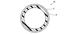
- the perspective view of the exhaust pipe of an Example is shown.
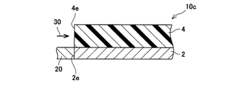
- the partially enlarged view of the radial cross section of the exhaust pipe of an Example is shown.
- the radial sectional view of the exhaust pipe of an Example is shown.
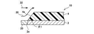
- the partially enlarged view of the longitudinal cross section of the exhaust pipe of an Example is shown.
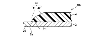
- a partially enlarged view of the longitudinal cross section of the exhaust pipe of the modified example is shown.
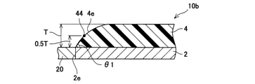
- a partially enlarged view of the longitudinal cross section of the exhaust pipe of the modified example is shown.
- a partially enlarged view of a longitudinal cross section of a conventional exhaust pipe is shown.
- the results of the experimental example are shown.
- the results of the experimental example are shown.
- the exhaust pipe disclosed in the present specification includes a metal pipe and an inorganic porous layer provided at a portion of the inner surface of the metal pipe through which the exhaust gas passes. Therefore, the heat transfer of the exhaust gas to the metal pipe is suppressed (the metal pipe is insulated), and the temperature drop of the exhaust gas is suppressed.
- the term "porous” as used herein means that the porosity (porosity) of the inorganic porous layer is 45% by volume or more.
- the inorganic porous layer protrudes into the exhaust gas flow path.
- the exhaust gas exerts a force on the side wall of the inorganic porous layer (the end face in the longitudinal direction of the exhaust pipe), and the inorganic porous layer may be peeled off or the inorganic porous layer may be damaged.
- the exhaust pipe disclosed in the present specification adjusts the shape of the end portion of the inorganic porous layer, reduces the force applied to the inorganic porous layer from the exhaust gas, and improves the durability of the inorganic porous layer.
- the thickness of the inorganic porous layer becomes thicker from the longitudinal end portion of the exhaust pipe toward the longitudinal central portion.
- the inorganic porous layer has a tapered shape that becomes thinner toward the longitudinal end edge.
- the exhaust gas flowing into the exhaust pipe can smoothly move in the exhaust pipe along the tapered side wall of the inorganic porous layer. That is, the force applied from the exhaust gas to the side wall of the inorganic porous layer is suppressed. Therefore, it is possible to prevent the inorganic porous layer from peeling off from the metal tube and the inorganic porous layer from being damaged.
- the exhaust pipe can improve the durability of the inorganic porous layer without reducing the thickness of the inorganic porous layer (while maintaining the heat insulating property).
- the ends of the inorganic porous layer may be tapered at both ends of the exhaust pipe, or the ends of the inorganic porous layer may be tapered at one end of the exhaust pipe. When the tapered shape is formed at one end of the exhaust pipe, the exhaust pipe is arranged so that the side where the tapered shape is formed is located upstream of the exhaust system.
- the angle (hereinafter referred to as a taper angle) formed by the back surface (the surface in contact with the inner surface of the metal pipe) and the side surface (the end surface in the longitudinal direction of the exhaust pipe) of the inorganic porous layer is 10 degrees or more and 60 degrees or less. It's okay.
- the taper angle is 10 degrees or more, the exhaust gas moving along the tapered side wall of the inorganic porous layer collides with the exhaust gas moving straight along the longitudinal direction of the exhaust pipe, and the exhaust gas of the exhaust gas Molecular motion is promoted.
- the molecular motion of the exhaust gas is promoted, the temperature drop of the exhaust gas is suppressed.
- the taper angle of the inorganic porous layer may be 20 degrees or more, 30 degrees or more, 40 degrees or more, or 50 degrees or more. Further, the taper angle of the inorganic porous layer may be 50 degrees or less, 40 degrees or less, 30 degrees or less, or 20 degrees or less.
- the inorganic porous layer may contain ceramic fibers. Further, the inorganic porous layer may be composed of 15% by mass or more of an alumina component and 45% by mass or more of a titania component. Since the inorganic porous layer contains ceramic fibers, the inorganic porous layer itself can absorb the influence of the difference in the coefficient of thermal expansion between the metal tube and the inorganic porous layer. Further, when the inorganic porous layer contains ceramic fibers, it is possible to suppress a decrease in the strength (mechanical strength) of the inorganic porous layer itself.
- the shape of the inorganic porous layer can be maintained even when exposed to high-temperature exhaust gas. ..
- the alumina component contained in the inorganic porous layer may be 25% by mass or more, 30% by mass or more, or 40% by mass or more.
- Equation 1 0.5 ⁇ 1 / ⁇ 2 ⁇ 1.2
- the inorganic porous layer may contain flat plate-shaped plate-shaped ceramic particles.
- the plate-shaped ceramic particles may have an aspect ratio of 10 or more and 60 or less when the cross section is observed by SEM.
- the aspect ratio of the cross section of the plate-shaped ceramic particles contained in the inorganic porous layer can be confirmed by observing the cross section of the inorganic porous layer by SEM.
- the plate-shaped ceramic particles appear in a rod shape in the SEM.
- the plate-shaped ceramic particles can suppress a decrease in the strength (mechanical strength) of the inorganic porous layer itself.
- the plate-shaped ceramic particles having a cross-sectional aspect ratio of 10 or more and 60 or less can have an aspect ratio in the manufacturing process of the inorganic porous layer by using, for example, plate-shaped ceramic particles having a cross-sectional aspect ratio of 60 or more and 100 or less as a raw material. Becomes smaller and remains in the inorganic porous as a result.
- the plate-shaped ceramic particles By using the plate-shaped ceramic particles, a part of the ceramic fiber can be replaced with the plate-shaped ceramic particles.
- the length of the plate-like ceramic particles (longitudinal size) is shorter than the length of the ceramic fibers.
- the heat transfer path in the inorganic porous layer is divided, and heat transfer in the inorganic porous layer is less likely to occur.
- the heat insulating performance of the inorganic porous layer is further improved.
- the inorganic porous layer may contain granular particles of 0.1 ⁇ m or more and 10 ⁇ m or less. When the inorganic porous layer is formed (baked), the ceramic fibers are bonded to each other via granular particles to obtain a high-strength inorganic porous layer.
- the thickness of the inorganic porous layer may be 1 mm or more, although it depends on the required performance. The above-mentioned function (heat insulating property) can be fully exhibited. If the thickness of the inorganic porous layer is too thick, it becomes difficult to obtain an improvement in characteristics commensurate with the cost (manufacturing cost, material cost). Therefore, although not particularly limited, the thickness of the inorganic porous layer may be 30 mm or less, 20 mm or less, 15 mm or less, 10 mm or less, and 5 mm or less.
- the difference in thermal conductivity between the metal tube and the inorganic porous layer is large.
- the thermal conductivity of the metal tube may be 100 times or more the thermal conductivity of the inorganic porous layer.
- the thermal conductivity of the metal tube may be 150 times or more the thermal conductivity of the inorganic porous layer, 200 times or more the thermal conductivity of the inorganic porous layer, and the heat of the inorganic porous layer.
- the conductivity may be 250 times or more, and the thermal conductivity of the inorganic porous layer may be 300 times or more.
- the thermal conductivity of the metal tube may be 10 W / mK or more and 400 W / mK or less.
- the thermal conductivity of the metal tube may be 25 W / mK or more, 50 W / mK or more, 100 W / mK or more, 150 W / mK or more, and 200 W / mK or more. It may be 250 W / mK or more, 300 W / mK or more, or 380 W / mK or more.
- the thermal conductivity of the metal tube may be 350 W / mK or less, 300 W / mK or less, 250 W / mK or less, 200 W / mK or less, 150 W / mK or less. May be.
- the thermal conductivity of the inorganic porous layer may be 0.05 W / mK or more and 3 W / mK or less.
- the thermal conductivity of the inorganic porous layer may be 0.1 W / mK or more, 0.2 W / mK or more, 0.3 W / mK or more, and 0.5 W / mK or more. It may be 0.7 W / mK or more, 1 W / mK or more, 1.5 W / mK or more, or 2 W / mK or more.
- the thermal conductivity of the inorganic porous layer may be 2.5 W / mK or less, 2.0 W / mK or less, 1.5 W / mK or less, and 1 W / mK or less. It may be 0.5 W / mK or less, 0.3 W / mK or less, and 0.25 W / mK or less.
- the metal tube may be linear, the whole (or a part) may be curved, the intermediate portion may be tapered, or the metal tube may be a branch tube.
- the inorganic porous layer may cover the entire surface (inner surface) of the metal tube, or may cover a part of the surface of the metal tube.
- the inorganic porous layer may cover a portion other than the end portion (one end or both ends) of the metal tube.
- the inorganic porous layer may be made of a uniform material in the thickness direction (range from the surface in contact with the metal pipe to the surface constituting the flow path of the exhaust gas). That is, the inorganic porous layer may be a single layer. Further, the inorganic porous layer may be composed of a plurality of layers having different compositions in the thickness direction. That is, the inorganic porous layer may have a multi-layer structure in which a plurality of layers are laminated. Alternatively, the inorganic porous layer may have an inclined structure in which the composition gradually changes in the thickness direction. When the inorganic porous layer is a single layer, the exhaust pipe can be easily manufactured (the step of forming the inorganic porous layer on the inner surface of the metal pipe).
- the characteristics of the inorganic porous layer can be changed in the thickness direction.
- the structure of the inorganic porous layer can be appropriately selected depending on the exhaust pipe.
- the porosity of the inorganic porous layer may be 45% by volume or more and 90% by volume or less. When the porosity is 45% by volume or more, the heat insulating property can be sufficiently exhibited. Further, if the porosity is 45% by volume or more, sufficient strength can be secured if the porosity is 90% by volume or less.
- the porosity of the inorganic porous layer may be 55% by volume or more, 60% by volume or more, or 65% by volume or more. Further, the porosity of the inorganic porous layer may be 85% by volume or less, 80% by volume or less, 70% by volume or less, 65% by volume or less, and 60% by volume. It may be as follows.
- the porosity of the inorganic porous layer may be 45% by volume or more and 90% by volume or less as a whole, and the porosity may differ in the thickness direction. .. In this case, there may be a portion having a porosity of less than 45% by volume or a portion having a porosity of more than 90% by volume.
- the inorganic porous layer is composed of one or more materials of ceramic particles (granular particles), plate-shaped ceramic particles, and ceramic fibers.
- the ceramic particles, the plate-shaped ceramic particles, and the ceramic fibers may contain alumina and / or titania as constituent components.
- the ceramic particles, the plate-shaped ceramic particles, and the ceramic fibers may be formed by alumina and / or titania. That is, the inorganic porous layer may contain 15% by mass or more of an alumina component and 45% by mass or more of a titania component in the entire constituent material (constituting substance).
- the inorganic porous layer contains at least ceramic fibers, although the constituent components are arbitrary (alumina component and titania component may or may not be contained).
- the ceramic particles may be used as a bonding material for joining aggregates forming the skeleton of an inorganic porous layer such as plate-shaped ceramic particles and ceramic fibers.
- the ceramic particles may be granular particles of 0.1 ⁇ m or more and 10 ⁇ m or less.
- the ceramic particles may have a larger particle size due to sintering or the like in the manufacturing process (for example, firing process). That is, as a raw material for producing the inorganic porous layer, the ceramic particles may be granular particles having a size of 0.1 ⁇ m or more and 10 ⁇ m or less (average particle size before firing).
- the ceramic particles may be 0.5 ⁇ m or more, and may be 5 ⁇ m or less.
- a metal oxide may be used as the material of the ceramic particles.
- metal oxide alumina (Al 2 O 3), spinel (MgAl 2 O 4), titania (TiO 2), zirconia (ZrO 2), magnesia (MgO), mullite (Al 6 O 13 Si 2) , cordierite (MgO ⁇ Al 2 O 3 ⁇ SiO 2), yttria (Y 2 O 3), steatite (MgO ⁇ SiO 2), forsterite (2MgO ⁇ SiO 2), lanthanum aluminate (LaAlO 3), strontium titanate (SrTiO 3 ) and the like can be mentioned.
- These metal oxides have high corrosion resistance. Therefore, by using the above metal oxide as a material for ceramic particles, it can be suitably applied as a protective layer for an exhaust pipe.
- the plate-shaped ceramic can function as an aggregate or a reinforcing material in the inorganic porous layer. That is, the plate-shaped ceramic, like the ceramic fiber, improves the strength of the inorganic porous layer and further suppresses the shrinkage of the inorganic porous layer in the manufacturing process. By using the plate-shaped ceramic particles, the heat transfer path in the inorganic porous layer can be divided. Therefore, by using the plate-shaped ceramic, the heat insulating property can be improved as compared with the form in which only the ceramic fiber is used as the aggregate.
- the surface shape (shape observed from the thickness direction) of the flat plate-shaped ceramic particles is not particularly limited, and is, for example, a polygon such as a rectangle, a substantially circular shape, a curved line, and / or an indefinite shape surrounded by a straight line.
- the longitudinal size when observing the cross section may be 5 ⁇ m or more and 100 ⁇ m or less. When the size in the longitudinal direction is 5 ⁇ m or more, excessive sintering of the ceramic particles can be suppressed. When the size in the longitudinal direction is 100 ⁇ m or less, the effect of dividing the heat transfer path in the inorganic porous layer can be obtained as described above, and it can be suitably applied to an exhaust pipe through which high-temperature exhaust gas flows.
- the plate-shaped ceramic particles may have an aspect ratio of 5 or more and 100 or less.
- the aspect ratio is 5 or more, the sintering of the ceramic particles can be satisfactorily suppressed, and when the aspect ratio is 100 or less, the decrease in the strength of the plate-shaped ceramic particles itself is suppressed.
- talc Mg 3 Si 4 O 10 (OH) 2
- minerals such as mica and kaolin, clay, glass and the like. Can also be used.
- the ceramic fiber can function as an aggregate or a reinforcing material in the inorganic porous layer. That is, the ceramic fiber improves the strength of the inorganic porous layer and further suppresses the shrinkage of the inorganic porous layer in the manufacturing process.
- the length of the ceramic fiber in the raw material for forming the inorganic porous layer may be 50 ⁇ m or more and 200 ⁇ m or less.
- the diameter (average diameter) of the ceramic fiber may be 1 to 20 ⁇ m.
- the ceramic fiber can be confirmed by observing the cross section of the inorganic porous layer by SEM.
- the ceramic fibers are substantially circular in the SEM image. That is, the radial cross section of the ceramic fiber appears in the SEM image.
- the ceramic fiber can be discriminated (confirmed) by performing EDS analysis.
- the volume fraction of the ceramic fiber in the raw material for forming the inorganic porous layer may be 5% by volume or more and 25% by volume or less.
- the raw material of the inorganic porous layer contains 5% by volume or more of ceramic fibers, the shrinkage of the ceramic particles in the inorganic porous layer can be sufficiently suppressed in the manufacturing process (firing step) of the inorganic porous layer.
- the heat transfer path in the inorganic porous layer is set. It can be divided and can be suitably applied to an exhaust pipe.
- the ratio (volume ratio) of the ceramic fiber in the inorganic porous layer should be measured by image processing the result of EDS analysis. Can be done.
- alumina Al 2 O 3
- spinel MgAl 2 O 4
- titania TiO 2
- zirconia ZrO 2
- magnesia MgO
- mullite Al 6 O 13 Si 2
- cordierite MgO ⁇ Al 2 O 3 ⁇ SiO 2
- yttria Y 2 O 3
- steatite MgO ⁇ SiO 2
- forsterite 2MgO ⁇ SiO 2
- LaAlO 3 lanthanum aluminate
- strontium The same material as the above-mentioned ceramic particles such as titanate (SrTiO 3) can be used.
- the inorganic porous layer may contain one or more kinds of ceramic fibers formed of the above materials.
- the content of aggregates and reinforcing materials (ceramic fibers, plate-shaped ceramic particles, etc., hereinafter simply referred to as aggregates) in the raw materials for forming the inorganic porous layer is 15% by mass or more and 55% by mass or less. May be.
- the content of the aggregate in the raw material is 15% by mass or more, the shrinkage of the inorganic porous layer in the firing step can be sufficiently suppressed.
- the content of the aggregate in the raw material is 55% by mass or less, the aggregates are satisfactorily bonded to each other by the ceramic particles.
- the content of the aggregate in the raw material may be 20% by mass or more, 30% by mass or more, 50% by mass or more, or 53% by mass or more.
- the content of the aggregate in the raw material may be 53% by mass or less, 50% by mass or less, 30% by mass or less, or 20% by mass or less.
- both the ceramic fiber and the plate-shaped ceramic particle can function as an aggregate and a reinforcing material in the inorganic porous layer.
- the inorganic porous layer is used.
- the content of the ceramic fiber in the raw material when forming the layer may be at least 5% by mass or more.
- the content of the ceramic fiber in the raw material may be 10% by mass or more, 20% by mass or more, 30% by mass or more, or 40% by mass or more.
- the content of the ceramic fiber in the raw material may be 50% by mass or less, 40% by mass or less, 30% by mass or less, 20% by mass or less, and 10% by mass. It may be less than or equal to%.
- the ratio (weight ratio) of the plate-shaped ceramic particles to the entire aggregate may be 70% or less. That is, in terms of mass ratio, at least 30% or more of the aggregate may be ceramic fibers.
- the ratio (weight ratio) of the plate-shaped ceramic particles to the total aggregate may be 67% or less, 64% or less, 63% or less, 60% or less, and 50. It may be less than or equal to%.
- the plate-shaped ceramic particles are not always essential as an aggregate.
- the ratio of the plate-shaped ceramic particles to the entire aggregate may be 40% or more, 50% or more, 60% or more, 62% or more, 63% or more. It may be 65% or more.
- the content of the plate-shaped ceramic particles in the raw material for forming the inorganic porous layer may be 5% by mass or more, 10% by mass or more, and 20% by mass or more. It may be 30% by mass or more, and may be 33% by mass or more.
- the content of the plate-shaped ceramic particles in the raw material may be 35% by mass or less, 33% by mass or less, 30% by mass or less, or 20% by mass or less. It may be 10% by mass or less.
- SiO 2 contained in the inorganic porous layer may be 25% by mass or less.
- the formation of an amorphous layer in the inorganic porous layer is suppressed, and the heat resistance (durability) of the inorganic porous layer is improved.
- a raw material in which a binder, a pore-forming material, and a solvent are mixed may be used in addition to ceramic particles, plate-shaped ceramic particles, and ceramic fibers.
- a binder an inorganic binder may be used.
- the inorganic binder include alumina sol, silica sol, titania sol, zirconia sol and the like. These inorganic binders can improve the strength of the inorganic porous layer after firing.
- a polymer-based pore-forming material, carbon-based powder, or the like may be used as the pore-forming material.
- the pore-forming material may have various shapes depending on the purpose, and may be, for example, spherical, plate-shaped, fibrous, or the like. By selecting the addition amount, size, shape, etc. of the pore-forming material, the porosity and pore size of the inorganic porous layer can be adjusted.
- the solvent may be any solvent as long as the viscosity of the raw material can be adjusted without affecting other raw materials, and for example, water, ethanol, isopropyl alcohol (IPA) or the like can be used.
- the above-mentioned inorganic binder is also a constituent material of the inorganic porous layer. Therefore, when alumina sol, titania sol, etc. are used to form the inorganic porous layer, the inorganic porous layer contains 15% by mass or more of the alumina component and 45% by mass or more of the titania component in the entire constituent material including the inorganic binder. It may be included.
- the composition and raw material of the inorganic porous layer are adjusted according to the metal tube to be protected.
- stainless steel such as SUS430, SUS424, SUS444, iron, cast iron, copper, Hastelloy, Inconel, Kovar, nickel alloy and the like can be used.
- the composition and raw material of the inorganic porous layer may be adjusted according to the coefficient of thermal expansion of the metal tube used. Specifically, when the coefficient of thermal expansion of the inorganic porous layer is ⁇ 1 and the coefficient of thermal expansion of the metal is ⁇ 2, the adjustment may be made so as to satisfy the following equation 4.
- the coefficient of thermal expansion ⁇ 1 is 6 ⁇ 10 -6 / K ⁇ 1 ⁇ 14 ⁇ 10 -6 / K, and more preferably the coefficient of thermal expansion ⁇ 1 is 6 ⁇ 10 -6.
- the composition and raw materials of the inorganic porous layer may be adjusted so that / K ⁇ 1 ⁇ 11 ⁇ 10-6 / K.
- the coefficient of thermal expansion ⁇ 1 is 8.5 ⁇ 10 -6 / K ⁇ 1 ⁇ 20 ⁇ 10 -6 / K, and more preferably, the coefficient of thermal expansion ⁇ 1 is 8.5.
- composition and raw materials of the inorganic porous layer may be adjusted so that ⁇ 10-6 / K ⁇ 1 ⁇ 18 ⁇ 10-6 / K.
- the value of " ⁇ 1 / ⁇ 2" may be 0.55 or more, 0.6 or more, 0.65 or more, 0.75 or more, and 0.8. It may be the above. Further, the value of " ⁇ 1 / ⁇ 2" may be 1.15 or less, 1.1 or less, 1.05 or less, or 1.0 or less. Equation 4: 0.5 ⁇ 1 / ⁇ 2 ⁇ 1.2
- the above raw material may be applied to the inner surface of the metal pipe, dried and fired to form an inorganic porous layer on the inner surface of the metal pipe.
- a method for applying the raw material dip coating, spin coating, aerosol deposition (AD) method, brush coating, trowel coating, mold cast molding and the like can be used. If the target inorganic porous layer is thick, or if the inorganic porous layer has a multi-layer structure, the application of the raw material and the drying of the raw material are repeated multiple times to adjust the thickness to the target or the multi-layer structure. You may.
- the above coating method can also be applied as a coating method for forming a coating layer, which will be described later.
- a coating layer may be provided on the surface of the inorganic porous layer.
- the material of the coating layer may be a porous or dense ceramic.
- the porous ceramic used in the coating layer include zirconia (ZrO 2 ), partially stabilized zirconia, stabilized zirconia and the like.
- yttria-stabilized zirconia ZrO 2- Y 2 O 3 : YSZ
- a metal oxide obtained by adding Gd 2 O 3 , Yb 2 O 3 , Er 2 O 3, etc.
- the dense ceramic used in the coating layer examples include alumina, silica, zirconia and the like. Further, since the ceramic fiber is removed from the constituent material of the inorganic porous layer described above to obtain a low porosity (dense), it may be used as a coating layer. By using the porous or dense ceramic as the coating layer, the inorganic porous layer can be reinforced and the inorganic porous layer can be prevented from peeling off from the surface of the metal tube. When a dense ceramic is used as the coating layer, for example, it is possible to suppress the permeation of high-temperature gas through the inorganic porous layer and the retention of exhaust gas in the inorganic porous layer. As a result, the effect of suppressing the heat transfer of the exhaust gas to the metal pipe can be expected.
- the exhaust pipe 10 will be described with reference to FIGS. 1 to 4.
- the exhaust pipe 10 is provided with an inorganic porous layer 4 on the inner surface of a metal pipe 2 made of SUS430.
- the exhaust pipe 10 was manufactured by immersing the metal pipe 2 in the raw material slurry, drying and firing the metal pipe 2 with the outer surface of the metal pipe 2 masked.
- the pipe made by SUS430
- the pipe having an inner diameter of 47 mm, a thickness of 1.5 mm, and a length of 300 mm was immersed in the raw material slurry with the outer surface masked, and the inorganic porous layer was applied to the inner wall of the pipe.
- each sample was prepared by drying at 200 ° C. and calcining at 800 ° C.
- the raw material slurry of the inorganic porous layer 4 includes alumina fibers (average fiber length 140 ⁇ m), plate-shaped alumina particles (average particle diameter 6 ⁇ m), titania particles (average particle diameter 0.25 ⁇ m), and alumina sol (alumina amount 1. 1% by mass), acrylic resin (average particle size 8 ⁇ m), and ethanol were mixed to prepare the mixture.
- the raw material slurry was adjusted so that the viscosity was 3000 mPa ⁇ s.
- the metal tube 2 After immersing the metal tube 2 in the raw material slurry for the inorganic porous layer and applying the raw material to the inner surface of the metal tube 2, the metal tube 2 was put into a dryer and dried at 200 ° C. (atmospheric atmosphere) for 1 hour. As a result, an inorganic porous layer 4 having a thickness of 500 ⁇ m was formed on the inner surface of the metal tube 2. Then, the step of immersing the metal tube 2 in the raw material slurry for the inorganic porous layer and drying it was repeated four times to form the inorganic porous layer 4 having a thickness of 2 mm on the inner surface of the metal tube 2.
- the metal pipe 2 was placed in an electric furnace and fired at 800 ° C. in an atmospheric atmosphere to prepare an exhaust pipe 10.
- the inorganic porous layer 4 was formed on the entire inner surface of the metal tube 2 (see FIG. 3).
- the end portion of the inorganic porous layer 4 was polished with sandpaper, and the side wall 4e of the inorganic porous layer 4 was tapered. That is, in the exhaust pipe 10, the thickness of the inorganic porous layer 4 increases from the longitudinal end portion of the exhaust pipe 10 toward the longitudinal central portion.
- the timing for processing the side wall 4e of the inorganic porous layer 4 into a tapered shape should be performed after the fourth (last) application of the raw material (before drying) or after the fourth (last) drying (before firing). You can also.
- the side wall 4e of the inorganic porous layer 4 is tapered in a tapered shape without polishing. You can also do it.
- the exhaust pipe 10 is connected to the exhaust system of an internal combustion engine (not shown) via a connecting pipe 20.
- Exhaust gas 30 is introduced into the exhaust pipe 10 from the connecting pipe 20.
- the exhaust gas 32 moving near the inner wall of the connecting pipe 20 is introduced into the exhaust pipe 10, it is located on the center side (radial center side) of the exhaust pipe 10 along the tapered side wall 4e. While moving, it moves in the longitudinal direction of the exhaust pipe 10. Since the side wall 4e has a tapered shape, the exhaust gas 32 moves in the exhaust pipe 10 without applying an excessive force to the side wall 4e.
- the exhaust gas 32 collides with the side wall 4e of the inorganic porous layer 4 and exerts an excessive force on the inorganic porous layer 4. Therefore, the exhaust pipe 110 may deteriorate due to the use of the exhaust pipe 110 for a long period of time, such as cracks in the side wall 4e or peeling of the inorganic porous layer 4 from the metal pipe 2. Since the force applied to the side wall 4e of the exhaust pipe 10 is suppressed, deterioration of the inorganic porous layer 4 can be suppressed.
- the exhaust gas 32 moves to the center side of the exhaust pipe 10 along the tapered side wall 4e, it collides with the exhaust gas 34 moving on the center side of the exhaust pipe 10.
- the exhaust gases exhaust gases 32 and 34
- the exhaust pipe 10 can suppress a decrease in the temperature of the exhaust gas (improve the heat insulating property) by causing the exhaust gases to collide with each other in the pipe.
- the taper angle ⁇ 1 of the inorganic porous layer 4 (the angle ⁇ 1 formed by the back surface of the inorganic porous layer 4 (contact surface with the metal tube 2) and the side wall 4e) is adjusted to 10 degrees or more and 60 degrees or less.
- the taper angle ⁇ 1 of the inorganic porous layer 4 is measured nondestructively using X-ray CT.
- the taper angle ⁇ 1 of the side wall 4e is substantially constant from the back surface to the front surface of the inorganic porous layer 4. That is, when observing the cross section of the inorganic porous layer 4, the side wall 4e is substantially straight. However, in the exhaust pipe 10a shown in FIG. 5, the taper angle of the side wall 4e changes on the way from the back surface to the front surface of the inorganic porous layer 4.
- the side wall 4e has a linear side wall 41 extending from the back surface of the inorganic porous layer 4 (the end edge in the longitudinal direction of the inorganic porous layer 4) and an inorganic side wall 41. It is composed of a linear side wall 42 extending from an intermediate portion in the thickness direction of the porous layer 4 to the surface.
- the exhaust pipe 10a can also suppress the excessive force applied from the exhaust gas to the side wall 4e, and can suppress the deterioration of the inorganic porous layer 4 while maintaining the heat insulating property.
- the angle ⁇ 1 formed by the back surface of the inorganic porous layer 4 and the side wall 41 is referred to as a taper angle of the side wall 4e.
- the side wall 4e appears as a curved line.
- the taper angle of the side wall 4e continues to change from the back surface to the front surface of the inorganic porous layer 4.
- the exhaust pipe 10b can also suppress the excessive force applied from the exhaust gas to the side wall 4e, and can suppress the deterioration of the inorganic porous layer 4 while maintaining the heat insulating property.
- the angle ⁇ 1 formed by the side wall 4e is referred to as a taper angle of the side wall 4e.
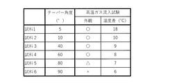
- Example 1 The taper angle ⁇ 1 of the side wall 4e of the inorganic porous layer 4 was changed, and the durability of the inorganic porous layer 4 and the heat insulating property of the exhaust pipe 10 were evaluated. Specifically, an inorganic porous layer 4 having a thickness of 2 mm is formed on the inner surface of a pipe made of SUS430 having an inner diameter of ⁇ 47 mm, a thickness of 1.5 mm, and a length of 300 mm, and a high-temperature gas inflow test is performed to perform durability and heat insulating properties. was evaluated.
- the raw material slurry for forming the inorganic porous layer 4 is a raw material in which 30% by mass of alumina fibers, 20% by mass of plate-shaped alumina particles, and 50% by mass of titania particles are mixed, and 10% by mass of alumina sol and 40% by mass of acrylic resin 40 are applied externally. It was prepared by adding mass% and adjusting the slurry viscosity with ethanol. Using this raw material slurry, the exhaust pipe 10 was manufactured by the above-mentioned method. In this case, the alumina component contained in the inorganic porous layer 4 is 51% by mass, and the titania component is 48% by mass.
- FIG. 8 shows the taper angle ⁇ 1 of each sample.
- the taper angle ⁇ 1 of each sample was measured using X-ray CT.
- the taper angle can be measured by using, for example, a three-dimensional measuring machine instead of the X-ray CT.
- the temperature difference between the pipes is small (10 degrees or less) at both ends in the longitudinal direction (gas inlet side and gas outlet side) of the exhaust pipe.
- the sample (Sample 1) having a taper angle of less than 10 degrees the temperature difference between the pipes is large (more than 10 degrees) at both ends in the longitudinal direction of the exhaust pipe. That is, it was confirmed that a sample having a taper angle of 10 degrees or more can obtain excellent heat insulating properties. This result shows that by setting the taper angle to 10 degrees or more, the exhaust gases can collide with each other in the exhaust pipe, and it is possible to suppress the decrease in the temperature of the exhaust gas.
- the side wall of the inorganic heat insulating layer is tapered so that the thickness of the inorganic porous layer becomes thicker from the longitudinal end to the longitudinal center of the exhaust pipe, thereby achieving high heat insulation and high height. It was confirmed that a durable exhaust pipe can be realized.
- Example 2 As described above, for the inorganic porous layer, a raw material slurry in which alumina fibers, plate-like alumina particles, titania particles, alumina sol, acrylic resin and ethanol are mixed is prepared, a metal tube is immersed in the raw material slurry, and then dried and It was created by firing.
- an inorganic porous layer was formed on the surface of the metal plate instead of the metal tube and evaluated.
- the proportions of the alumina fibers, the plate-shaped alumina particles and the titania particles were changed, and the alumina fibers were replaced with mullite fibers and the plate-shaped alumina particles were replaced with the plate-shaped mica to form an inorganic porous layer.
- the state of the inorganic porous layer after firing was confirmed.
- the blending amounts of ceramic fibers (alumina fibers,glasse fibers), plate-shaped ceramic particles (plate-shaped alumina particles, plate-shaped mica), titania particles, and zirconia particles are changed as shown in FIG. , Plate-shaped ceramic particles, titania particles and zirconia particles are blended so that the total is 100% by mass, and further, 10% by mass of alumina sol (1.1% by mass of alumina contained in the alumina sol), acrylic resin 40 A raw material slurry was prepared by adding mass% and adjusting the slurry viscosity with ethanol. The sample 15 does not use plate-shaped ceramic particles, and the samples 11 to 17, 20, 22 and 23 do not use zirconia particles.
- the raw material slurry was applied to the SUS430 plate, and for the samples 19 and 20, the raw material slurry was applied to the copper plate, dried at an air atmosphere of 200 ° C. for 1 hour, and then the air atmosphere 800. It was baked at ° C for 3 hours.
- the number of times the raw material slurry was applied (the number of times the metal plate was immersed) in each sample was adjusted so that an inorganic porous layer of about 1.2 mm was formed on the metal plate (SUS430 plate and copper plate).
- the purpose of this experimental example is to confirm the effect of the amounts of the alumina component (ceramic fiber, plate-shaped ceramic particles) and the titania component on the appearance of the inorganic porous layer (presence or absence of cracks, peeling, etc.).
- the heat insulating property of the porous layer has not been evaluated.
- the coefficient of thermal expansion was obtained by molding the above-mentioned raw material slurry into a bulk body of 3 mm ⁇ 4 mm ⁇ 20 mm and then calcining the bulk body at 800 ° C. to prepare a sample for measurement. Then, the measurement sample was measured using a thermal expansion meter in accordance with JIS R1618 (a method for measuring thermal expansion by thermomechanical analysis of fine ceramics). The coefficient of thermal expansion was measured separately for the inorganic porous layer and the metal plate.
- thermal conductivity of the inorganic porous layers of Samples 11 to 14 and 23 and the metal plates of Samples 11 to 23 was measured. Thermal conductivity was also measured separately for the inorganic porous layer and the metal plate. The thermal conductivity was calculated by multiplying the thermal diffusivity, the specific heat capacity and the bulk density. For the heat diffusion rate, a laser flash method heat constant measuring device is used, and for the specific heat capacity, a DSC (differential scanning calorimetry) is used. Method) was measured at room temperature.
- the bulk density (unit: g / cm 3 ) of the inorganic porous layer was calculated from the following formula (5).
- the thermal diffusivity is obtained by molding the above-mentioned raw material slurry into a bulk body having a diameter of 10 mm ⁇ 1 mm
- the specific heat capacity is obtained by molding the above-mentioned raw material slurry into a bulk body having a diameter of 5 mm ⁇ a thickness of 1 mm, and then each bulk body is 800.
- the proportion of the alumina component in the sample 21 is less than 15% by mass, it is presumed that the bonding force between the ceramics (particles, fibers) is reduced and cracks are generated in the inorganic porous layer. Further, since the proportion of the titania component in the sample 22 is less than 45% by mass, it is presumed that the bonding force between the ceramics is lowered and cracks are generated in the inorganic porous layer. Further, in the sample 22, the content of the titania component (titania particles) having a high coefficient of thermal expansion is low, and the ratio of the coefficient of thermal expansion to the metal ( ⁇ 1 / ⁇ 2) is small (less than 0.5).
- the inorganic porous layer was separated from the metal based on the difference in thermal expansion. From the above, regardless of the type of ceramic fiber (alumina fiber, mullite fiber) and the type of plate-shaped ceramic particles (plate-shaped alumina particle, plate-shaped mica), 15% by mass or more of alumina component and 45% by mass or more of titania component. It was confirmed that the inorganic porous layer containing the above was less likely to cause deterioration such as cracks and peeling after firing.
Landscapes
- Engineering & Computer Science (AREA)
- Chemical & Material Sciences (AREA)
- Ceramic Engineering (AREA)
- Organic Chemistry (AREA)
- Materials Engineering (AREA)
- General Engineering & Computer Science (AREA)
- Mechanical Engineering (AREA)
- Structural Engineering (AREA)
- Manufacturing & Machinery (AREA)
- Combustion & Propulsion (AREA)
- Chemical Kinetics & Catalysis (AREA)
- Metallurgy (AREA)
- Exhaust Silencers (AREA)
Priority Applications (1)
| Application Number | Priority Date | Filing Date | Title |
|---|---|---|---|
| JP2022536406A JPWO2022014616A1 (enExample) | 2020-07-13 | 2021-07-13 |
Applications Claiming Priority (2)
| Application Number | Priority Date | Filing Date | Title |
|---|---|---|---|
| JP2020120264 | 2020-07-13 | ||
| JP2020-120264 | 2020-07-13 |
Publications (1)
| Publication Number | Publication Date |
|---|---|
| WO2022014616A1 true WO2022014616A1 (ja) | 2022-01-20 |
Family
ID=79555586
Family Applications (1)
| Application Number | Title | Priority Date | Filing Date |
|---|---|---|---|
| PCT/JP2021/026363 Ceased WO2022014616A1 (ja) | 2020-07-13 | 2021-07-13 | 排気管 |
Country Status (2)
| Country | Link |
|---|---|
| JP (1) | JPWO2022014616A1 (enExample) |
| WO (1) | WO2022014616A1 (enExample) |
Citations (8)
| Publication number | Priority date | Publication date | Assignee | Title |
|---|---|---|---|---|
| JPS60175720A (ja) * | 1984-02-20 | 1985-09-09 | Honda Motor Co Ltd | 内燃機関用消音器 |
| JPH02225383A (ja) * | 1988-11-21 | 1990-09-07 | Hitachi Metals Ltd | セラミック・鉄製部材接合体及びその製造法 |
| JPH06239656A (ja) * | 1993-02-12 | 1994-08-30 | Ibiden Co Ltd | 触媒用断熱材 |
| US20070151799A1 (en) * | 2005-12-30 | 2007-07-05 | Bilal Zuberi | Catalytic fibrous exhaust system and method for catalyzing an exhaust gas |
| JP2009057862A (ja) * | 2007-08-30 | 2009-03-19 | Hino Motors Ltd | 断熱排気管 |
| KR20100061432A (ko) * | 2010-05-18 | 2010-06-07 | 김창선 | 단열내화 디젤 엔진 및 그것을 이용한 발전기용 고효율 엔진 |
| WO2013081150A1 (ja) * | 2011-12-02 | 2013-06-06 | 日本碍子株式会社 | エンジン燃焼室構造、および流路の内壁構造 |
| WO2020145366A1 (ja) * | 2019-01-10 | 2020-07-16 | 日本碍子株式会社 | 複合部材 |
-
2021
- 2021-07-13 WO PCT/JP2021/026363 patent/WO2022014616A1/ja not_active Ceased
- 2021-07-13 JP JP2022536406A patent/JPWO2022014616A1/ja active Pending
Patent Citations (8)
| Publication number | Priority date | Publication date | Assignee | Title |
|---|---|---|---|---|
| JPS60175720A (ja) * | 1984-02-20 | 1985-09-09 | Honda Motor Co Ltd | 内燃機関用消音器 |
| JPH02225383A (ja) * | 1988-11-21 | 1990-09-07 | Hitachi Metals Ltd | セラミック・鉄製部材接合体及びその製造法 |
| JPH06239656A (ja) * | 1993-02-12 | 1994-08-30 | Ibiden Co Ltd | 触媒用断熱材 |
| US20070151799A1 (en) * | 2005-12-30 | 2007-07-05 | Bilal Zuberi | Catalytic fibrous exhaust system and method for catalyzing an exhaust gas |
| JP2009057862A (ja) * | 2007-08-30 | 2009-03-19 | Hino Motors Ltd | 断熱排気管 |
| KR20100061432A (ko) * | 2010-05-18 | 2010-06-07 | 김창선 | 단열내화 디젤 엔진 및 그것을 이용한 발전기용 고효율 엔진 |
| WO2013081150A1 (ja) * | 2011-12-02 | 2013-06-06 | 日本碍子株式会社 | エンジン燃焼室構造、および流路の内壁構造 |
| WO2020145366A1 (ja) * | 2019-01-10 | 2020-07-16 | 日本碍子株式会社 | 複合部材 |
Also Published As
| Publication number | Publication date |
|---|---|
| JPWO2022014616A1 (enExample) | 2022-01-20 |
Similar Documents
| Publication | Publication Date | Title |
|---|---|---|
| CN113272475B (zh) | 复合部件 | |
| US9028946B2 (en) | Ceramic honeycomb structure with applied inorganic skin | |
| EP1506948B1 (en) | Honeycomb structural body | |
| US20110176972A1 (en) | Cellular structure containing aluminium titanate | |
| WO2022014613A1 (ja) | 排気管 | |
| US12153012B2 (en) | Gas sensor | |
| US8642137B2 (en) | Ceramic honeycomb structure and its production method | |
| US5171721A (en) | Ceramic green sheet for porous layer, electrochemical element using the green sheet, and method of producing the element | |
| JP2013522020A (ja) | 閉塞材料を有するフィルター材料 | |
| JP7178420B2 (ja) | セラミックス構造体およびガスセンサのセンサ素子 | |
| WO2007125667A1 (ja) | ハニカム構造体 | |
| US20220252540A1 (en) | Sensor element | |
| JP6423360B2 (ja) | 断熱膜、および断熱膜構造 | |
| WO2022014614A1 (ja) | 排気管 | |
| WO2022014616A1 (ja) | 排気管 | |
| JP2022017128A (ja) | 複合部材 | |
| WO2022014615A1 (ja) | 排気管 | |
| WO2022014611A1 (ja) | 複合部材 | |
| WO2022014617A1 (ja) | 排気管 | |
| WO2022014612A1 (ja) | 排気管 | |
| US20110143928A1 (en) | Catalytic filter or substrate containing silicon carbide and aluminum titanate | |
| JP7743345B2 (ja) | 排気管 | |
| WO2015053242A1 (ja) | ガス流通部材 | |
| JP2946975B2 (ja) | 断熱性を有するセラミック皮膜 | |
| CN111747770B (zh) | 蜂窝结构体 |
Legal Events
| Date | Code | Title | Description |
|---|---|---|---|
| 121 | Ep: the epo has been informed by wipo that ep was designated in this application |
Ref document number: 21842455 Country of ref document: EP Kind code of ref document: A1 |
|
| ENP | Entry into the national phase |
Ref document number: 2022536406 Country of ref document: JP Kind code of ref document: A |
|
| NENP | Non-entry into the national phase |
Ref country code: DE |
|
| 122 | Ep: pct application non-entry in european phase |
Ref document number: 21842455 Country of ref document: EP Kind code of ref document: A1 |