WO2022014611A1 - 複合部材 - Google Patents
複合部材 Download PDFInfo
- Publication number
- WO2022014611A1 WO2022014611A1 PCT/JP2021/026358 JP2021026358W WO2022014611A1 WO 2022014611 A1 WO2022014611 A1 WO 2022014611A1 JP 2021026358 W JP2021026358 W JP 2021026358W WO 2022014611 A1 WO2022014611 A1 WO 2022014611A1
- Authority
- WO
- WIPO (PCT)
- Prior art keywords
- porous layer
- inorganic porous
- metal
- composite member
- less
- Prior art date
Links
- 239000002131 composite material Substances 0.000 title claims abstract description 122
- 229910052751 metal Inorganic materials 0.000 claims abstract description 182
- 239000002184 metal Substances 0.000 claims abstract description 182
- 239000000919 ceramic Substances 0.000 claims abstract description 134
- 239000000835 fiber Substances 0.000 claims abstract description 71
- GWEVSGVZZGPLCZ-UHFFFAOYSA-N Titan oxide Chemical compound O=[Ti]=O GWEVSGVZZGPLCZ-UHFFFAOYSA-N 0.000 claims abstract description 58
- PNEYBMLMFCGWSK-UHFFFAOYSA-N aluminium oxide Inorganic materials [O-2].[O-2].[O-2].[Al+3].[Al+3] PNEYBMLMFCGWSK-UHFFFAOYSA-N 0.000 claims abstract description 46
- 239000011148 porous material Substances 0.000 claims abstract description 26
- 239000010410 layer Substances 0.000 claims description 290
- 239000002245 particle Substances 0.000 claims description 97
- 239000011247 coating layer Substances 0.000 claims description 28
- 239000002994 raw material Substances 0.000 description 54
- 239000000463 material Substances 0.000 description 33
- 238000010304 firing Methods 0.000 description 24
- 239000002002 slurry Substances 0.000 description 20
- MCMNRKCIXSYSNV-UHFFFAOYSA-N Zirconium dioxide Chemical compound O=[Zr]=O MCMNRKCIXSYSNV-UHFFFAOYSA-N 0.000 description 16
- 239000007789 gas Substances 0.000 description 15
- 238000000034 method Methods 0.000 description 14
- 238000004519 manufacturing process Methods 0.000 description 12
- 238000012546 transfer Methods 0.000 description 12
- 238000012360 testing method Methods 0.000 description 11
- LFQSCWFLJHTTHZ-UHFFFAOYSA-N Ethanol Chemical compound CCO LFQSCWFLJHTTHZ-UHFFFAOYSA-N 0.000 description 10
- CPLXHLVBOLITMK-UHFFFAOYSA-N Magnesium oxide Chemical compound [Mg]=O CPLXHLVBOLITMK-UHFFFAOYSA-N 0.000 description 10
- 238000010438 heat treatment Methods 0.000 description 10
- 230000002093 peripheral effect Effects 0.000 description 9
- 229910004298 SiO 2 Inorganic materials 0.000 description 7
- 239000011230 binding agent Substances 0.000 description 7
- 239000002346 layers by function Substances 0.000 description 7
- 229920000178 Acrylic resin Polymers 0.000 description 6
- 239000004925 Acrylic resin Substances 0.000 description 6
- 229910018072 Al 2 O 3 Inorganic materials 0.000 description 6
- RYGMFSIKBFXOCR-UHFFFAOYSA-N Copper Chemical compound [Cu] RYGMFSIKBFXOCR-UHFFFAOYSA-N 0.000 description 6
- KFZMGEQAYNKOFK-UHFFFAOYSA-N Isopropanol Chemical compound CC(C)O KFZMGEQAYNKOFK-UHFFFAOYSA-N 0.000 description 6
- 239000000470 constituent Substances 0.000 description 6
- 229910052802 copper Inorganic materials 0.000 description 6
- 239000010949 copper Substances 0.000 description 6
- 238000001035 drying Methods 0.000 description 6
- QSHDDOUJBYECFT-UHFFFAOYSA-N mercury Chemical compound [Hg] QSHDDOUJBYECFT-UHFFFAOYSA-N 0.000 description 6
- 229910052753 mercury Inorganic materials 0.000 description 6
- 229910044991 metal oxide Inorganic materials 0.000 description 6
- 150000004706 metal oxides Chemical class 0.000 description 6
- 238000000465 moulding Methods 0.000 description 6
- 239000011241 protective layer Substances 0.000 description 6
- 239000012779 reinforcing material Substances 0.000 description 6
- 238000009826 distribution Methods 0.000 description 5
- -1 lanthanum aluminate Chemical class 0.000 description 5
- 238000012986 modification Methods 0.000 description 5
- 230000004048 modification Effects 0.000 description 5
- XEEYBQQBJWHFJM-UHFFFAOYSA-N Iron Chemical compound [Fe] XEEYBQQBJWHFJM-UHFFFAOYSA-N 0.000 description 4
- 230000008859 change Effects 0.000 description 4
- 238000000576 coating method Methods 0.000 description 4
- 238000002485 combustion reaction Methods 0.000 description 4
- 230000006866 deterioration Effects 0.000 description 4
- KZHJGOXRZJKJNY-UHFFFAOYSA-N dioxosilane;oxo(oxoalumanyloxy)alumane Chemical compound O=[Si]=O.O=[Si]=O.O=[Al]O[Al]=O.O=[Al]O[Al]=O.O=[Al]O[Al]=O KZHJGOXRZJKJNY-UHFFFAOYSA-N 0.000 description 4
- 230000000694 effects Effects 0.000 description 4
- 239000011521 glass Substances 0.000 description 4
- 239000000395 magnesium oxide Substances 0.000 description 4
- 239000010445 mica Substances 0.000 description 4
- 229910052618 mica group Inorganic materials 0.000 description 4
- 229910052863 mullite Inorganic materials 0.000 description 4
- 230000008569 process Effects 0.000 description 4
- 238000005245 sintering Methods 0.000 description 4
- 239000010936 titanium Substances 0.000 description 4
- 229910010413 TiO 2 Inorganic materials 0.000 description 3
- 230000000274 adsorptive effect Effects 0.000 description 3
- 239000000567 combustion gas Substances 0.000 description 3
- 230000007423 decrease Effects 0.000 description 3
- 230000006872 improvement Effects 0.000 description 3
- 229910010272 inorganic material Inorganic materials 0.000 description 3
- 239000011147 inorganic material Substances 0.000 description 3
- 238000005259 measurement Methods 0.000 description 3
- 238000002156 mixing Methods 0.000 description 3
- 230000035939 shock Effects 0.000 description 3
- 239000002356 single layer Substances 0.000 description 3
- 239000002904 solvent Substances 0.000 description 3
- 239000000126 substance Substances 0.000 description 3
- 238000010998 test method Methods 0.000 description 3
- 230000004580 weight loss Effects 0.000 description 3
- 229910001233 yttria-stabilized zirconia Inorganic materials 0.000 description 3
- OKTJSMMVPCPJKN-UHFFFAOYSA-N Carbon Chemical compound [C] OKTJSMMVPCPJKN-UHFFFAOYSA-N 0.000 description 2
- 229910021193 La 2 O 3 Inorganic materials 0.000 description 2
- 229910020068 MgAl Inorganic materials 0.000 description 2
- ATUOYWHBWRKTHZ-UHFFFAOYSA-N Propane Chemical compound CCC ATUOYWHBWRKTHZ-UHFFFAOYSA-N 0.000 description 2
- VYPSYNLAJGMNEJ-UHFFFAOYSA-N Silicium dioxide Chemical compound O=[Si]=O VYPSYNLAJGMNEJ-UHFFFAOYSA-N 0.000 description 2
- RTAQQCXQSZGOHL-UHFFFAOYSA-N Titanium Chemical compound [Ti] RTAQQCXQSZGOHL-UHFFFAOYSA-N 0.000 description 2
- 229910052782 aluminium Inorganic materials 0.000 description 2
- XAGFODPZIPBFFR-UHFFFAOYSA-N aluminium Chemical compound [Al] XAGFODPZIPBFFR-UHFFFAOYSA-N 0.000 description 2
- 230000015572 biosynthetic process Effects 0.000 description 2
- 239000003054 catalyst Substances 0.000 description 2
- 239000011248 coating agent Substances 0.000 description 2
- 229910052878 cordierite Inorganic materials 0.000 description 2
- 238000000113 differential scanning calorimetry Methods 0.000 description 2
- JSKIRARMQDRGJZ-UHFFFAOYSA-N dimagnesium dioxido-bis[(1-oxido-3-oxo-2,4,6,8,9-pentaoxa-1,3-disila-5,7-dialuminabicyclo[3.3.1]nonan-7-yl)oxy]silane Chemical compound [Mg++].[Mg++].[O-][Si]([O-])(O[Al]1O[Al]2O[Si](=O)O[Si]([O-])(O1)O2)O[Al]1O[Al]2O[Si](=O)O[Si]([O-])(O1)O2 JSKIRARMQDRGJZ-UHFFFAOYSA-N 0.000 description 2
- 238000002149 energy-dispersive X-ray emission spectroscopy Methods 0.000 description 2
- 229910052839 forsterite Inorganic materials 0.000 description 2
- 238000009413 insulation Methods 0.000 description 2
- 229910052742 iron Inorganic materials 0.000 description 2
- 229910052746 lanthanum Inorganic materials 0.000 description 2
- HCWCAKKEBCNQJP-UHFFFAOYSA-N magnesium orthosilicate Chemical compound [Mg+2].[Mg+2].[O-][Si]([O-])([O-])[O-] HCWCAKKEBCNQJP-UHFFFAOYSA-N 0.000 description 2
- 230000000873 masking effect Effects 0.000 description 2
- 150000002739 metals Chemical class 0.000 description 2
- 239000000203 mixture Substances 0.000 description 2
- 238000005192 partition Methods 0.000 description 2
- 239000000843 powder Substances 0.000 description 2
- 238000001878 scanning electron micrograph Methods 0.000 description 2
- 229910010271 silicon carbide Inorganic materials 0.000 description 2
- HBMJWWWQQXIZIP-UHFFFAOYSA-N silicon carbide Chemical compound [Si+]#[C-] HBMJWWWQQXIZIP-UHFFFAOYSA-N 0.000 description 2
- 239000007787 solid Substances 0.000 description 2
- 229910052596 spinel Inorganic materials 0.000 description 2
- 239000011029 spinel Substances 0.000 description 2
- VEALVRVVWBQVSL-UHFFFAOYSA-N strontium titanate Chemical compound [Sr+2].[O-][Ti]([O-])=O VEALVRVVWBQVSL-UHFFFAOYSA-N 0.000 description 2
- 229910052623 talc Inorganic materials 0.000 description 2
- 229910052719 titanium Inorganic materials 0.000 description 2
- RUDFQVOCFDJEEF-UHFFFAOYSA-N yttrium(III) oxide Inorganic materials [O-2].[O-2].[O-2].[Y+3].[Y+3] RUDFQVOCFDJEEF-UHFFFAOYSA-N 0.000 description 2
- 239000005995 Aluminium silicate Substances 0.000 description 1
- 229910001018 Cast iron Inorganic materials 0.000 description 1
- 229920000877 Melamine resin Polymers 0.000 description 1
- 239000004640 Melamine resin Substances 0.000 description 1
- 229910000990 Ni alloy Inorganic materials 0.000 description 1
- 240000007594 Oryza sativa Species 0.000 description 1
- 235000007164 Oryza sativa Nutrition 0.000 description 1
- 239000004698 Polyethylene Substances 0.000 description 1
- 239000004793 Polystyrene Substances 0.000 description 1
- 238000010521 absorption reaction Methods 0.000 description 1
- 239000002253 acid Substances 0.000 description 1
- 239000000443 aerosol Substances 0.000 description 1
- 235000012211 aluminium silicate Nutrition 0.000 description 1
- 238000004458 analytical method Methods 0.000 description 1
- 239000005388 borosilicate glass Substances 0.000 description 1
- 238000001354 calcination Methods 0.000 description 1
- 229910052799 carbon Inorganic materials 0.000 description 1
- 239000006229 carbon black Substances 0.000 description 1
- 238000005266 casting Methods 0.000 description 1
- 238000006243 chemical reaction Methods 0.000 description 1
- 239000004927 clay Substances 0.000 description 1
- 230000008602 contraction Effects 0.000 description 1
- 230000007797 corrosion Effects 0.000 description 1
- 238000005260 corrosion Methods 0.000 description 1
- 238000005336 cracking Methods 0.000 description 1
- 238000000151 deposition Methods 0.000 description 1
- 230000008021 deposition Effects 0.000 description 1
- 238000007607 die coating method Methods 0.000 description 1
- 238000009792 diffusion process Methods 0.000 description 1
- 238000003618 dip coating Methods 0.000 description 1
- 238000011156 evaluation Methods 0.000 description 1
- 229910000856 hastalloy Inorganic materials 0.000 description 1
- 230000017525 heat dissipation Effects 0.000 description 1
- 229910001026 inconel Inorganic materials 0.000 description 1
- 238000002347 injection Methods 0.000 description 1
- 239000007924 injection Substances 0.000 description 1
- 229910052500 inorganic mineral Inorganic materials 0.000 description 1
- 238000005304 joining Methods 0.000 description 1
- NLYAJNPCOHFWQQ-UHFFFAOYSA-N kaolin Chemical compound O.O.O=[Al]O[Si](=O)O[Si](=O)O[Al]=O NLYAJNPCOHFWQQ-UHFFFAOYSA-N 0.000 description 1
- 230000014759 maintenance of location Effects 0.000 description 1
- 238000000691 measurement method Methods 0.000 description 1
- 238000002844 melting Methods 0.000 description 1
- 230000008018 melting Effects 0.000 description 1
- 239000011707 mineral Substances 0.000 description 1
- 229910052575 non-oxide ceramic Inorganic materials 0.000 description 1
- 239000011225 non-oxide ceramic Substances 0.000 description 1
- 229910002077 partially stabilized zirconia Inorganic materials 0.000 description 1
- 229920000573 polyethylene Polymers 0.000 description 1
- 229920000642 polymer Polymers 0.000 description 1
- 229920002223 polystyrene Polymers 0.000 description 1
- 238000007639 printing Methods 0.000 description 1
- 238000012545 processing Methods 0.000 description 1
- 239000001294 propane Substances 0.000 description 1
- 235000009566 rice Nutrition 0.000 description 1
- RMAQACBXLXPBSY-UHFFFAOYSA-N silicic acid Chemical compound O[Si](O)(O)O RMAQACBXLXPBSY-UHFFFAOYSA-N 0.000 description 1
- 239000000377 silicon dioxide Substances 0.000 description 1
- 239000008279 sol Substances 0.000 description 1
- 238000004528 spin coating Methods 0.000 description 1
- 239000007921 spray Substances 0.000 description 1
- 238000005507 spraying Methods 0.000 description 1
- 229910002076 stabilized zirconia Inorganic materials 0.000 description 1
- 239000010935 stainless steel Substances 0.000 description 1
- 229910001220 stainless steel Inorganic materials 0.000 description 1
- 238000006467 substitution reaction Methods 0.000 description 1
- 239000000454 talc Substances 0.000 description 1
- 238000007751 thermal spraying Methods 0.000 description 1
- 230000000930 thermomechanical effect Effects 0.000 description 1
- XLYOFNOQVPJJNP-UHFFFAOYSA-N water Substances O XLYOFNOQVPJJNP-UHFFFAOYSA-N 0.000 description 1
Images


Classifications
-
- B—PERFORMING OPERATIONS; TRANSPORTING
- B32—LAYERED PRODUCTS
- B32B—LAYERED PRODUCTS, i.e. PRODUCTS BUILT-UP OF STRATA OF FLAT OR NON-FLAT, e.g. CELLULAR OR HONEYCOMB, FORM
- B32B15/00—Layered products comprising a layer of metal
- B32B15/04—Layered products comprising a layer of metal comprising metal as the main or only constituent of a layer, which is next to another layer of the same or of a different material
-
- B—PERFORMING OPERATIONS; TRANSPORTING
- B32—LAYERED PRODUCTS
- B32B—LAYERED PRODUCTS, i.e. PRODUCTS BUILT-UP OF STRATA OF FLAT OR NON-FLAT, e.g. CELLULAR OR HONEYCOMB, FORM
- B32B3/00—Layered products comprising a layer with external or internal discontinuities or unevennesses, or a layer of non-planar shape; Layered products comprising a layer having particular features of form
- B32B3/26—Layered products comprising a layer with external or internal discontinuities or unevennesses, or a layer of non-planar shape; Layered products comprising a layer having particular features of form characterised by a particular shape of the outline of the cross-section of a continuous layer; characterised by a layer with cavities or internal voids ; characterised by an apertured layer
- B32B3/266—Layered products comprising a layer with external or internal discontinuities or unevennesses, or a layer of non-planar shape; Layered products comprising a layer having particular features of form characterised by a particular shape of the outline of the cross-section of a continuous layer; characterised by a layer with cavities or internal voids ; characterised by an apertured layer characterised by an apertured layer, the apertures going through the whole thickness of the layer, e.g. expanded metal, perforated layer, slit layer regular cells B32B3/12
-
- C—CHEMISTRY; METALLURGY
- C23—COATING METALLIC MATERIAL; COATING MATERIAL WITH METALLIC MATERIAL; CHEMICAL SURFACE TREATMENT; DIFFUSION TREATMENT OF METALLIC MATERIAL; COATING BY VACUUM EVAPORATION, BY SPUTTERING, BY ION IMPLANTATION OR BY CHEMICAL VAPOUR DEPOSITION, IN GENERAL; INHIBITING CORROSION OF METALLIC MATERIAL OR INCRUSTATION IN GENERAL
- C23C—COATING METALLIC MATERIAL; COATING MATERIAL WITH METALLIC MATERIAL; SURFACE TREATMENT OF METALLIC MATERIAL BY DIFFUSION INTO THE SURFACE, BY CHEMICAL CONVERSION OR SUBSTITUTION; COATING BY VACUUM EVAPORATION, BY SPUTTERING, BY ION IMPLANTATION OR BY CHEMICAL VAPOUR DEPOSITION, IN GENERAL
- C23C26/00—Coating not provided for in groups C23C2/00 - C23C24/00
Definitions
- An inorganic protective layer may be provided on the surface of the metal to form a composite member of the metal and the inorganic material.
- Japanese Patent Application Laid-Open No. 2018-33245 (hereinafter referred to as Patent Document 1) covers a metal surface with an inorganic protective layer mainly in order to impart heat resistance to an automobile engine component (metal).
- Patent Document 1 in order to prevent the inorganic protective layer from peeling from the metal due to the difference in the coefficient of thermal expansion between the metal and the inorganic protective layer, an amorphous inorganic material layer (specifically, borosilicate acid) is provided on the metal surface.
- Patent Document 1 a relaxation layer (borosilicate glass) for reducing the difference in thermal expansion coefficient between the metal and the functional layer (silicon carbide) that functions as a protective layer is provided. There is. Patent Document 1 improves the adhesion between the metal and the functional layer by providing an amorphous relaxation layer.
- Patent Document 1 provides an amorphous relaxation layer between the metal and the functional layer. Therefore, when forming the functional layer, it is necessary to form the functional layer at a temperature not exceeding the softening point of the relaxation layer. In other words, the material that can be used as the functional layer is limited to the material that can be formed into a film under the condition that the softening point of the relaxation layer is not exceeded. Therefore, the composite member of Patent Document 1 has a low degree of freedom in the materials (relaxation layer, functional layer) that can be used. Further, since the composite member of Patent Document 1 uses an amorphous relaxation layer, the improvement of heat resistance is limited. Therefore, continuous improvement is needed in the field of composite materials. It is an object of the present specification to provide a novel composite member which has never existed in the past.
- the composite member disclosed in the present specification may be provided with an inorganic porous layer on the surface of the metal.
- the inorganic porous layer contains ceramic fibers and is composed of an alumina component of 15% by mass or more and a titania component of 45% by mass or more, and the pore diameter may be 1 ⁇ m or more and 30 ⁇ m or less.
- An example (perspective view) of the composite member of the first embodiment is shown.
- a partially enlarged view of the composite member of the first embodiment is shown.
- the sectional view of the composite material of 1st Example is shown.
- a modification (cross-sectional view) of the composite material of the first embodiment is shown.
- a modification (cross-sectional view) of the composite material of the first embodiment is shown.
- a modification (cross-sectional view) of the composite material of the first embodiment is shown.
- An example (perspective view) of the composite member of the second embodiment is shown.
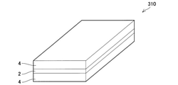
- An example (perspective view) of the composite member of the third embodiment is shown.
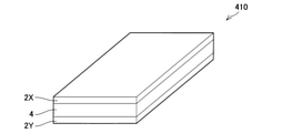
- An example (perspective view) of the composite member of the fourth embodiment is shown.
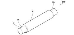
- An example (perspective view) of the composite member of the fifth embodiment is shown.
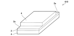
- An example (perspective view) of the composite member of the sixth embodiment is shown.
- An example (perspective view) of the composite member of the seventh embodiment is shown.
- An example (perspective view) of the composite member of the eighth embodiment is shown.
- An example of use (cross-sectional view) of the composite member is shown.
- the results of the experimental example are shown.
- the results of the experimental example are shown.
- the SEM photograph of the inorganic porous layer is shown.
- the composite material disclosed herein has an inorganic porous layer on the surface of the metal.
- the inorganic porous body typically has a high ability to "cut off" the internal and external environment through the inorganic porous body. Therefore, the composite member suppresses the influence of the external environment on the metal, or suppresses the influence of the metal on the external environment, and realizes high heat insulation, high sound insulation (sound absorption), and the like. be able to.
- the composite member can also prevent substances in the external environment (foreign matter, moisture, etc.) from coming into contact with the metal, such as adsorptivity and hygroscopicity, due to the inorganic porous layer.
- a catalyst or the like can be supported on the metal surface by utilizing the inorganic porous layer.
- porous as used herein means that the porosity (porosity) of the inorganic porous layer is 45% by volume or more.
- the composite member disclosed in the present specification can be suitably used, for example, in a high temperature environment.
- the composite member can be suitably used as a member constituting an exhaust system of an automobile such as an exhaust manifold and an exhaust pipe (exhaust pipe).
- the composite member disclosed in the present specification can be suitably used as, for example, a heat conductive member that transfers heat generated by a heat source to a component (for example, a heat sink) existing at a position away from the heat source.
- a composite member may be arranged between a plurality of devices and preferably used as a partition plate for preventing heat generated from one device from being applied to the other device.
- the inorganic porous layer may contain ceramic fibers.
- the ceramic fiber can function as an aggregate or a reinforcing material in the inorganic porous layer. That is, the ceramic fiber improves the strength of the inorganic porous layer and further suppresses the shrinkage of the inorganic porous layer in the manufacturing process.
- the length of the ceramic fiber in the raw material for forming the inorganic porous layer may be 50 ⁇ m or more and 200 ⁇ m or less.
- the diameter (average diameter) of the ceramic fiber may be 1 to 20 ⁇ m.
- the volume fraction of the ceramic fiber in the raw material for forming the inorganic porous layer may be 5% by volume or more and 25% by volume or less.
- the shrinkage of the ceramic particles in the inorganic porous layer can be sufficiently suppressed in the manufacturing process (firing step) of the inorganic porous layer. Further, by setting the volume ratio of the ceramic fiber in the raw material to 25% by volume or less, the heat transfer path in the inorganic porous layer can be divided, and the heat transfer to the metal can be suitably suppressed.
- the ceramic fiber can absorb the influence of the difference in the coefficient of thermal expansion between the metal and the inorganic porous layer.
- the inorganic porous layer can be deformed following the deformation (thermal expansion, thermal contraction) of the metal, it is possible to prevent the inorganic porous layer from peeling from the metal. That is, the adhesion between the metal and the inorganic porous layer is improved.
- the composite material is used as the exhaust pipe of the internal combustion engine, the inorganic porous layer can suppress the exhaust gas from coming into contact with the metal (metal pipe) and suppress the deterioration of the metal pipe.
- the ceramic fiber can function as an aggregate or a reinforcing material in the inorganic porous layer. That is, the ceramic fiber improves the strength of the inorganic porous layer and further suppresses the shrinkage of the inorganic porous layer in the manufacturing process.
- the length of the ceramic fiber may be 50 ⁇ m or more and 200 ⁇ m or less.
- the diameter (average diameter) of the ceramic fiber may be 1 to 20 ⁇ m.
- the ceramic fiber can be confirmed by observing the cross section of the inorganic porous layer by SEM.
- the ceramic fibers are substantially circular in the SEM image. That is, the radial cross section of the ceramic fiber appears in the SEM image.
- the ceramic fiber can be discriminated (confirmed) by performing EDS analysis.
- the volume fraction of the ceramic fiber in the raw material for forming the inside of the inorganic porous layer may be 5% by volume or more and 25% by volume or less.
- the raw material of the inorganic porous layer contains 5% by volume or more of ceramic fibers, the shrinkage of the ceramic particles in the inorganic porous layer can be sufficiently suppressed in the manufacturing process (firing step) of the inorganic porous layer.
- the volume ratio of the ceramic fibers in the raw material is set. It can be divided and heat transfer to the metal can be suitably suppressed.
- the ratio (volume ratio) of the ceramic fiber in the inorganic porous layer should be measured by image processing the result of EDS analysis. Can be done.
- the inorganic porous layer may contain one or more kinds of ceramic fibers formed of the above materials.
- the inorganic porous layer may be composed of 15% by mass or more of an alumina component and 45% by mass or more of a titania component.
- Such an inorganic porous layer has a high melting point of the inorganic porous layer itself, and can maintain its shape even when the external environment of the composite member becomes high temperature.
- the porosity of the inorganic porous layer may be 45% by volume or more and 90% by volume or less.
- the functions of being porous such as heat insulating property, sound insulating property, adsorptive property, and hygroscopic property can be sufficiently exhibited.
- the porosity is 45% by volume or more, the voids in the inorganic porous layer can be utilized to sufficiently support the catalyst.
- the porosity is 90% by volume or less, sufficient strength can be secured.
- the porosity of the inorganic porous layer may be 55% by volume or more, 60% by volume or more, or 65% by volume or more.
- the porosity of the inorganic porous layer may be 85% by volume or less, 80% by volume or less, 70% by volume or less, 65% by volume or less, and 60% by volume. It may be as follows.
- the porosity of the inorganic porous layer may be 45% by volume or more and 90% by volume or less as a whole, and the porosity may differ in the thickness direction. .. In this case, there may be a portion having a porosity of less than 45% by volume or a portion having a porosity of more than 90% by volume.
- the pore diameter of the inorganic porous layer may be 1 ⁇ m or more and 30 ⁇ m or less.
- the skeleton (mesh-like skeleton) of the inorganic porous layer becomes sufficiently thick, and the strength of the inorganic porous layer can be ensured.
- the pore diameter is 30 ⁇ m or less, the structure of the inorganic porous layer (skeleton, the substance that binds the skeleton, etc.) is suppressed from becoming non-uniform, and a local fragile portion is generated in the inorganic porous layer. Can be suppressed.
- the "pore diameter” can be measured using a mercury porosimeter in accordance with JIS R1655 (a molded body pore diameter distribution test method by a mercury injection method for fine ceramics).
- the "pore diameter” as used herein means the median diameter obtained from the pore diameter distribution map obtained by the above measurement.
- the pore diameter may be 2 ⁇ m or more, 5 ⁇ m or more, 10 ⁇ m or more, 15 ⁇ m or more, or 20 ⁇ m or more.
- the pore diameter may be 25 ⁇ m or less, 20 ⁇ m or less, 15 ⁇ m or less, 10 ⁇ m or less, or 5 ⁇ m or less.
- Equation 1 0.5 ⁇ 1 / ⁇ 2 ⁇ 1.2
- the inorganic porous layer may contain flat plate-shaped plate-shaped ceramic particles.
- the plate-shaped ceramic particles may have an aspect ratio of 10 or more and 60 or less when the cross section is observed by SEM.
- the aspect ratio of the cross section of the plate-shaped ceramic particles contained in the inorganic porous layer can be confirmed by observing the cross section of the inorganic porous layer by SEM.
- the plate-shaped ceramic particles appear in a rod shape in the SEM.
- the plate-shaped ceramic particles can suppress a decrease in the strength (mechanical strength) of the inorganic porous layer itself.
- the plate-shaped ceramic particles having a cross-sectional aspect ratio of 10 or more and 60 or less have an aspect ratio in the manufacturing process of the inorganic porous layer by using, for example, plate-shaped ceramic particles having a cross-sectional aspect ratio of 60 or more and 100 or less as a raw material. The ratio becomes smaller and as a result remains in the inorganic porous material.
- the inorganic porous layer is formed by using plate-shaped ceramic particles having an aspect ratio of 60 or more and 100 or less as a raw material, sintering of the ceramic particles can be appropriately suppressed, and the inorganic porous is formed after production (after firing). It is possible to prevent the layer from becoming too hard (the Young's modulus becomes too high).
- the inorganic porous layer when a composite material is used as an exhaust pipe of an internal combustion engine, the inorganic porous layer has appropriate toughness (Young's modulus is not too high), so that thermal shock (inorganic porous in a low temperature state) immediately after the start of the internal combustion engine is performed. It is possible to prevent the inorganic porous layer from being damaged (cracking or the like) due to contact with high-temperature exhaust gas. Further, since the strength of the inorganic porous layer is maintained by the plate-shaped ceramic particles, it is possible to prevent the inorganic porous layer from being damaged by the vibration of the exhaust pipe or the gas flow of the exhaust gas.
- the inorganic porous layer may contain granular particles of 0.1 ⁇ m or more and 10 ⁇ m or less.
- aggregates such as ceramic fibers are bonded to each other via granular particles to obtain a high-strength inorganic porous layer.
- the thickness of the inorganic porous layer may be 1 mm or more.
- the inorganic porous layer can be molded to 1 mm or more by containing a material (plate-shaped ceramic particles, ceramic fiber) that is unlikely to shrink in the molding process (for example, firing step). ..
- a material plate-shaped ceramic particles, ceramic fiber
- the inorganic porous layer shrinks during the molding process and cracks or the like occur. Therefore, when the inorganic porous layer does not contain ceramic fibers or the like. It is difficult to form an inorganic porous layer into a thick film of 1 mm or more.
- the inorganic porous layer is composed of 15% by mass or more of an alumina (Al 2 O 3 ) component and 45% by mass or more of a titania (TIO 2 ) component.
- the alumina component contained in the inorganic porous layer may be 25% by mass or more, 30% by mass or more, or 40% by mass or more.
- the inorganic porous layer may cover the metal surface and protect the metal from the external environment.
- the "external environment” means the space on the opposite side of the metal via the inorganic porous layer. That is, when the composite material is a member constituting the exhaust system of an automobile as described above, the "external environment” corresponds to an internal space such as an exhaust manifold or an exhaust pipe.
- the inorganic porous layer may cover the metal surface and protect (insulate) the parts existing in the external environment of the composite member from the heat of the metal. Further, the inorganic porous layer may cover the surfaces of both of two metals (for example, a metal plate) facing each other at intervals.
- metal plates may be bonded to both sides of one inorganic porous layer. It is possible to prevent heat generated from the first device arranged on the first metal plate side from being applied to the second device arranged on the second metal plate side, and the first metal plate allows the first device. The generated heat can be dissipated.
- the composite member suppresses the influence of heat on each other by the metal and the external environment due to the inorganic porous layer.
- the inorganic porous layer separates the space in which a plurality of devices are arranged, and suppresses the influence of heat on the separated spaces. Therefore, it is preferable that the difference in thermal conductivity between the metal and the inorganic porous layer is large.
- the thermal conductivity of the metal may be 100 times or more the thermal conductivity of the inorganic porous layer.
- the thermal conductivity of the metal may be 150 times or more the thermal conductivity of the inorganic porous layer, 200 times or more the thermal conductivity of the inorganic porous layer, and the thermal conductivity of the inorganic porous layer.
- the rate may be 250 times or more, and may be 300 times or more the thermal conductivity of the inorganic porous layer.
- the thermal conductivity of the metal may be 10 W / mK or more and 400 W / mK or less.
- the thermal conductivity of the metal may be 25 W / mK or more, 50 W / mK or more, 100 W / mK or more, 150 W / mK or more, and 200 W / mK or more. It may be 250 W / mK or more, 300 W / mK or more, or 380 W / mK or more.
- the thermal conductivity of the metal may be 350 W / mK or less, 300 W / mK or less, 250 W / mK or less, 200 W / mK or less, 150 W / mK or less. There may be.
- the thermal conductivity of the inorganic porous layer may be 0.05 W / mK or more and 3 W / mK or less.
- the thermal conductivity of the inorganic porous layer may be 0.1 W / mK or more, 0.2 W / mK or more, 0.3 W / mK or more, and 0.5 W / mK or more. It may be 0.7 W / mK or more, 1 W / mK or more, 1.5 W / mK or more, or 2 W / mK or more.
- the thermal conductivity of the inorganic porous layer may be 2.5 W / mK or less, 2.0 W / mK or less, 1.5 W / mK or less, and 1 W / mK or less. It may be 0.5 W / mK or less, 0.3 W / mK or less, and 0.25 W / mK or less.
- the shape of the metal is not particularly limited, but may be tubular (cylindrical), linear (wire), or plate (sheet).
- the inorganic porous layer may cover the inner peripheral surface and / or the outer peripheral surface of the tubular metal.
- Linear metals are typically solid structures. Therefore, in the case of a linear metal, the inorganic porous layer may cover the outer peripheral surface of the linear metal.
- the inorganic porous layer may cover the entire exposed surface of the plate metal, or may cover the surface (front surface and / or back surface) of the end portion in the thickness direction. However, the surface (side surface) of the end portion in the width direction may be covered, or the surface of the end portion in the length direction may be covered. Further, in the case of a plate metal, the inorganic porous layer covers both the front surface of the first plate metal (first metal plate) and the back surface of the second plate metal (second metal plate). good.
- the metal tube When the metal is tubular, the metal tube may be a single tube or a multiple tube (for example, a double tube).
- the metal tube may be linear, the whole (or a part) may be curved, the intermediate portion may be tapered, or the metal tube may be a branch tube.
- the inorganic porous layer may be provided on the inner surface of the metal tube in the case of a single tube, or on the inner surface of the metal tube arranged on the innermost side in the case of a multiple tube.
- the inorganic porous layer may cover the entire inner surface of the metal tube or a part of the inner surface of the metal tube.
- the inorganic porous layer may cover a portion other than the end portion (one end or both ends) of the metal tube.
- the inorganic porous layer may cover the entire surface of the metal or may cover a part of the metal surface.
- the inorganic porous layer may cover a portion other than the end portion (one end or both ends) of the metal.
- the inorganic porous layer covers the inner peripheral surface and the outer peripheral surface of the tubular metal, the inner peripheral surface is covered with the inorganic porous layer from one end to the other end (that is, the entire surface is covered), and the outer peripheral surface is the end.
- the range covered with the inorganic porous layer may be different between the inner peripheral surface and the outer peripheral surface, such as the portion excluding the portion being covered.
- the inorganic porous layer covers the plate-like metal (for example, the surface of the end portion in the thickness direction: the front and back surfaces)
- the inorganic porous layer is a part of the front and back surfaces (for example, one end or both ends in the longitudinal direction).
- the part other than the part) may be covered.
- the inorganic porous layer may have a different range of coverage on the front and back surfaces, such as covering the entire back surface and covering the front surface, for example, a portion excluding both ends.
- the inorganic porous layer may be made of a uniform material in the thickness direction. That is, the inorganic porous layer may be a single layer. Further, the inorganic porous layer may be composed of a plurality of layers having different compositions in the thickness direction. That is, the inorganic porous layer may have a multi-layer structure in which a plurality of layers are laminated. Alternatively, the inorganic porous layer may have an inclined structure in which the composition gradually changes in the thickness direction. When the inorganic porous layer is a single layer, the composite member can be easily manufactured (the step of forming the inorganic porous layer on the metal surface).
- the inorganic porous layer has a multi-layered or inclined structure
- the characteristics of the inorganic porous layer can be changed in the thickness direction.
- the structure of the inorganic porous layer (single layer, multi-layer, inclined structure) can be appropriately selected as needed.
- the thickness of the inorganic porous layer may be 1 mm or more, although it depends on the purpose of use (required performance).
- the functions of being porous such as heat insulating property, sound insulating property, adsorptive property, and hygroscopic property can be sufficiently exhibited.
- it is difficult to maintain the thickness at 1 mm or more because it shrinks in the manufacturing process (for example, firing step). If it contains ceramic fibers or the like, shrinkage in the manufacturing process is suppressed, and a thickness of 1 mm or more can be maintained.
- the thickness of the inorganic porous layer may be 30 mm or less, 20 mm or less, 15 mm or less, 10 mm or less, and 5 mm or less.
- the inorganic porous layer is composed of one or more materials of ceramic particles (granular particles), plate-shaped ceramic particles, and ceramic fibers.
- the ceramic particles, the plate-shaped ceramic particles, and the ceramic fibers may contain alumina and / or titania as constituent components.
- the ceramic particles, the plate-shaped ceramic particles, and the ceramic fibers may be formed by alumina and / or titania. That is, the inorganic porous layer may contain 15% by mass or more of an alumina component and 45% by mass or more of a titania component in the entire constituent material (constituting substance).
- the inorganic porous layer may or may not contain an alumina component and a titania component as constituent components, but preferably contains at least ceramic fibers.
- the ceramic particles may be used as a bonding material for joining aggregates forming the skeleton of an inorganic porous layer such as plate-shaped ceramic particles and ceramic fibers.
- the ceramic particles may be granular particles of 0.1 ⁇ m or more and 10 ⁇ m or less.
- the ceramic particles may have a larger particle size due to sintering or the like in the manufacturing process (for example, firing process). That is, as a raw material for producing the inorganic porous layer, the ceramic particles may be granular particles having a size of 0.1 ⁇ m or more and 10 ⁇ m or less (average particle size before firing).
- the ceramic particles may be 0.5 ⁇ m or more, and may be 5 ⁇ m or less.
- a metal oxide may be used as the material of the ceramic particles.
- a metal oxide alumina (Al 2 O 3), spinel (MgAl 2 O 4), titania (TiO 2), zirconia (ZrO 2), magnesia (MgO), mullite (Al 6 O 13 Si 2) , cordierite (MgO ⁇ Al 2 O 3 ⁇ SiO 2), yttria (Y 2 O 3), steatite (MgO ⁇ SiO 2), forsterite (2MgO ⁇ SiO 2), lanthanum aluminate (LaAlO 3), strontium titanate (SrTiO 3 ) and the like can be mentioned.
- These metal oxides have high corrosion resistance. Therefore, by using the metal oxide as the material of the ceramic particles, the inorganic porous layer can be suitably applied as a protective layer for, for example, parts (exhaust pipes and the like) of an automobile exhaust system.
- the plate-shaped ceramic can function as an aggregate or a reinforcing material in the inorganic porous layer. That is, the plate-shaped ceramic, like the ceramic fiber, improves the strength of the inorganic porous layer and further suppresses the shrinkage of the inorganic porous layer in the manufacturing process. By using the plate-shaped ceramic particles, the heat transfer path in the inorganic porous layer can be divided. Therefore, when the composite member is used in a high temperature environment (when the inorganic porous layer is used for the purpose of insulating the metal), the heat insulating property can be improved as compared with the form in which only the ceramic fiber is used as the aggregate. ..
- the surface shape (shape observed from the thickness direction) of the flat plate-shaped ceramic particles is not particularly limited, and is, for example, a polygon such as a rectangle, a substantially circular shape, a curved line, and / or an indefinite shape surrounded by a straight line.
- the longitudinal size when observing the cross section may be 5 ⁇ m or more and 100 ⁇ m or less. When the size in the longitudinal direction is 5 ⁇ m or more, excessive sintering of the ceramic particles can be suppressed. When the size in the longitudinal direction is 100 ⁇ m or less, the effect of dividing the heat transfer path in the inorganic porous layer can be obtained as described above, and it can be suitably applied to a composite member used in a high temperature environment.
- the plate-shaped ceramic particles may have an aspect ratio of 10 or more and 60 or less in cross section.
- the aspect ratio of the cross section is 10 or more, the sintering of the ceramic particles can be satisfactorily suppressed, and high resistance to thermal shock can be obtained.
- the aspect ratio of the cross section is 60 or less, the decrease in strength of the plate-shaped ceramic particles themselves is suppressed, and high resistance to mechanical impact (vibration or the like) can be obtained.
- the composite member is an exhaust pipe of an internal combustion engine, it is possible to prevent the inorganic porous layer from being damaged by the vibration of the exhaust pipe or the gas flow of the exhaust gas.
- talc Mg 3 Si 4 O 10 (OH) 2
- minerals such as mica and kaolin, clay, glass and the like. Can also be used.
- the content of aggregates and reinforcing materials (ceramic fibers, plate-shaped ceramic particles, etc., hereinafter simply referred to as aggregates) in the raw materials for forming the inorganic porous layer is 15% by mass or more and 55% by mass or less. May be.
- the content of the aggregate in the raw material of the inorganic porous layer is 15% by mass or more, the shrinkage of the inorganic porous layer in the firing step can be sufficiently suppressed.
- the content of the aggregate in the raw material is 55% by mass or less, the aggregates are satisfactorily bonded to each other by the ceramic particles.
- the content of the aggregate in the raw material may be 20% by mass or more, 30% by mass or more, 50% by mass or more, or 53% by mass or more.
- the content of the aggregate in the raw material may be 53% by mass or less, 50% by mass or less, 30% by mass or less, or 20% by mass or less.
- both the ceramic fiber and the plate-shaped ceramic particle can function as an aggregate and a reinforcing material in the inorganic porous layer.
- the inorganic porous layer is used.
- the content of the ceramic fiber in the raw material when forming the layer may be at least 5% by mass or more.
- the content of the ceramic fiber in the raw material may be 10% by mass or more, 20% by mass or more, 30% by mass or more, or 40% by mass or more.
- the content of the ceramic fiber in the raw material may be 50% by mass or less, 40% by mass or less, 30% by mass or less, 20% by mass or less, and 10% by mass. It may be less than or equal to%.
- the ratio of the plate-shaped ceramic particles to the entire aggregate may be 70% by mass or less. That is, in terms of mass ratio, at least 30% by mass or more of the aggregate may be ceramic fibers.
- the ratio of the plate-shaped ceramic particles to the entire aggregate may be 67% by mass or less, 64% by mass or less, 63% by mass or less, 60% by mass or less, and 50. It may be mass% or less.
- the plate-shaped ceramic particles are not always essential as an aggregate.
- the ratio of the plate-shaped ceramic particles to the entire aggregate may be 40% by mass or more, 50% by mass or more, 60% by mass or more, and 62% by mass or more. , 63% by mass or more, and may be 65% by mass or more.
- the content of the plate-shaped ceramic particles in the raw material for forming the inorganic porous layer may be 5% by mass or more and 35% by mass or less.
- 5% by mass or more of plate-shaped ceramic particles as the raw material of the inorganic porous layer it is possible to sufficiently suppress the shrinkage of the ceramic particles in the inorganic porous layer in the manufacturing process (firing step) of the inorganic porous layer. can.
- the content of the plate-shaped ceramic particles in the raw material to 35% by mass or less (that is, the proportion of the plate-shaped ceramic particles in the inorganic porous layer is 35% by mass or less)
- heat transfer in the inorganic porous layer is performed.
- the path can be disrupted and heat transfer to the metal can be suitably suppressed.
- the content of the plate-shaped ceramic particles in the raw material may be 5% by mass or more, 10% by mass or more, 20% by mass or more, 30% by mass or more, and 33% by mass. It may be% or more.
- the content of the plate-shaped ceramic particles in the raw material may be 35% by mass or less, 33% by mass or less, 30% by mass or less, or 20% by mass or less. It may be 10% by mass or less.
- the SiO 2 contained in the inorganic porous layer may be 25% by mass or less.
- the formation of an amorphous layer in the inorganic porous layer is suppressed, and the heat resistance (durability) of the inorganic porous layer is improved.
- a raw material in which a binder, a pore-forming material, and a solvent are mixed may be used in addition to ceramic particles, plate-shaped ceramic particles, and ceramic fibers.
- a binder an inorganic binder may be used.
- the inorganic binder include alumina sol, silica sol, titania sol, zirconia sol and the like. These inorganic binders can improve the strength of the inorganic porous layer after firing.
- a polymer-based pore-forming material, carbon-based powder, or the like may be used as the pore-forming material.
- the pore-forming material may have various shapes depending on the purpose, and may be, for example, spherical, plate-shaped, fibrous, or the like. By selecting the addition amount, size, shape, etc. of the pore-forming material, the porosity and pore size of the inorganic porous layer can be adjusted.
- the solvent may be any solvent as long as the viscosity of the raw material can be adjusted without affecting other raw materials, and for example, water, ethanol, isopropyl alcohol (IPA) or the like can be used.
- the above-mentioned inorganic binder is also a constituent material of the inorganic porous layer. Therefore, when alumina sol, titania sol, etc. are used to form the inorganic porous layer, the inorganic porous layer contains 15% by mass or more of the alumina component and 45% by mass or more of the titania component in the entire constituent material including the inorganic binder. It may be included.
- the composition and raw material of the inorganic porous layer are adjusted according to the type of metal to be protected.
- the composite member disclosed in the present specification is not particularly limited, and as the metal, stainless steel such as SUS430, SUS424, SUS444, iron, cast iron, copper, Hastelloy, Inconel, Koval, nickel alloy and the like can be used.
- the composition and raw material of the inorganic porous layer may be adjusted according to the coefficient of thermal expansion of the metal used. Specifically, when the coefficient of thermal expansion of the inorganic porous layer is ⁇ 1 and the coefficient of thermal expansion of the metal is ⁇ 2, the following equation 1 may be adjusted to be satisfied.
- thermal expansion coefficient [alpha] 1 is 6 ⁇ 10 -6 / K ⁇ 1 ⁇ 14 ⁇ 10 -6 / K, and more preferably, the thermal expansion coefficient [alpha] 1 is 6 ⁇ 10 -6 /
- the composition and raw materials of the inorganic porous layer may be adjusted so that K ⁇ 1 ⁇ 11 ⁇ 10 -6 / K.
- the coefficient of thermal expansion ⁇ 1 is 8.5 ⁇ 10-6 / K ⁇ 1 ⁇ 20 ⁇ 10-6 / K, and more preferably, the coefficient of thermal expansion ⁇ 1 is 8.5 ⁇ .
- composition and raw materials of the inorganic porous layer may be adjusted so that 10-6 / K ⁇ 1 ⁇ 18 ⁇ 10-6 / K.
- the value of " ⁇ 1 / ⁇ 2" may be 0.55 or more, 0.6 or more, 0.65 or more, 0.75 or more, and 0.8. It may be the above. Further, the value of " ⁇ 1 / ⁇ 2" may be 1.15 or less, 1.1 or less, 1.05 or less, or 1.0 or less. Equation 1: 0.5 ⁇ 1 / ⁇ 2 ⁇ 1.2
- the above raw material may be applied to a metal surface (in the case of a tubular metal, in a tube), dried and fired to form an inorganic porous layer on the metal surface.
- a method for applying the raw material dip coating, spin coating, spray coating, slit die coating, thermal spraying, aerosol deposition (AD) method, printing, brush coating, iron coating, mold casting and the like can be used. If the target inorganic porous layer is thick, or if the inorganic porous layer has a multi-layer structure, the application of the raw material and the drying of the raw material are repeated multiple times to adjust the thickness to the target or the multi-layer structure. You may.
- the above coating method can also be applied as a coating method for forming a coating layer, which will be described later.
- the coating layer may be provided on the surface of the inorganic porous layer opposite to the surface on which the metal is provided. That is, the inorganic porous layer may be sandwiched between the metal and the coating layer.
- the coating layer may be provided on the entire surface of the surface of the inorganic porous layer (the surface opposite to the surface on which the metal is provided), or may be provided on a part of the surface of the inorganic porous layer. You may. By providing the coating layer, the inorganic porous layer can be protected (reinforced).
- the material of the coating layer may be a porous or dense ceramic.
- the porous ceramic used in the coating layer include zirconia (ZrO 2 ), partially stabilized zirconia, stabilized zirconia and the like.
- yttria-stabilized zirconia ZrO 2- Y 2 O 3 : YSZ
- a metal oxide obtained by adding Gd 2 O 3 , Yb 2 O 3 , Er 2 O 3, etc.
- the dense ceramic used in the coating layer examples include alumina, silica, zirconia and the like. Further, by removing the ceramic fibers and the plate-shaped ceramic particles from the constituent materials of the above-mentioned inorganic porous layer, the porosity is low (dense), so that it may be used as a coating layer.
- a porous or dense ceramic as the coating layer, the inorganic porous layer can be reinforced and the inorganic porous layer can be prevented from peeling off from the surface of the metal.
- a dense ceramic is used as the coating layer, for example, it is possible to suppress the permeation of the high temperature gas through the inorganic porous layer and the retention of the high temperature gas in the inorganic porous layer.
- the effect of electrically insulating the metal from the external environment is improved.
- the composite member is used as an exhaust pipe, for example, it is possible to suppress the permeation of the exhaust gas through the inorganic porous layer, or to prevent the exhaust gas from staying in the inorganic porous layer. As a result, the effect of suppressing the heat transfer of the exhaust gas to the metal can be expected.
- the material of the coating layer may be porous or dense glass.
- the inorganic porous layer can be reinforced and the inorganic porous layer can be prevented from peeling off from the surface of the metal.
- the material of the coating layer may be a metal (a component separate from the metal protected by the inorganic porous layer).
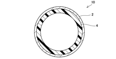
- the composite member 10 will be described with reference to FIGS. 1 to 3.
- the composite member 10 is provided with an inorganic porous layer 4 on the inner surface of a tubular metal (metal tube) 2 made of SUS430.
- the inorganic porous layer 4 is bonded to the inner surface of the metal 2 (see FIGS. 1 and 2).
- the composite member 10 was manufactured by immersing the metal 2 in a raw material slurry, drying and firing the metal 2 with the outer surface of the metal 2 masked.
- the raw material slurry includes alumina fibers (average fiber length 140 ⁇ m), plate-shaped alumina particles (average particle diameter 6 ⁇ m), titania particles (average particle diameter 0.25 ⁇ m), and alumina sol (alumina amount 1.1% by mass). It was prepared by mixing acrylic resin and ethanol. The raw material slurry was adjusted so that the viscosity was 2000 mPa ⁇ s.
- the metal 2 was immersed in the raw material slurry and the raw material was applied to the inner surface of the metal 2, the metal 2 was put into a dryer and dried at 200 ° C. (atmosphere) for 1 hour. As a result, an inorganic porous layer of about 300 ⁇ m was formed on the inner surface of the metal 2. Then, the step of immersing the metal 2 in the raw material slurry and drying it was repeated three times to form a 1.2 mm inorganic porous layer on the inner surface of the metal 2. Then, the metal 2 was placed in an electric furnace and fired at 800 ° C. (atmosphere) for 3 hours to prepare a composite member 10. The inorganic porous layer 4 was formed on the entire inner surface of the metal 2 (see FIG. 3).
- the porosity of the inorganic porous layer 4 was 61% by volume, and the coefficient of thermal expansion was 7 ⁇ 10 -6 K- 1 .
- titania particles are interposed between the surface (inner surface) of the metal 2 and the aggregate (alumina fibers and plate-like alumina particles) to form the inner surface of the metal 2 and the aggregate. It was confirmed that they were joined.
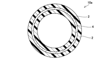
- FIGS. 4 to 6 show a portion of the composite member 10 corresponding to FIG. 3 (cross-sectional view).
- the inorganic porous layer 4 is joined to the inner surface and the outer surface of the metal 2.
- the composite member 10a was manufactured through substantially the same steps as the composite member 10 without masking the metal 2.
- the inorganic porous layer 4 was formed on the entire inner and outer surfaces of the metal 2.
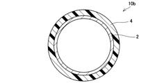
- the inorganic porous layer 4 is joined to the outer surface of the metal 2.
- the composite member 10b was manufactured through substantially the same steps as the composite member 10 with the inner surface of the metal 2 masked.
- the inorganic porous layer 4 was formed on the entire outer surface of the metal 2.
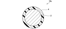
- the metal 2 is linear (line-shaped) and no hole is formed in the center (see FIGS. 1 to 5 for comparison). That is, in the composite member 10c, the metal 2 is solid.
- the inorganic porous layer 4 is joined to the outer surface of the metal 2.
- the composite member 10c was manufactured through substantially the same steps as the composite member 10 without masking the metal 2.
- the inorganic porous layer 4 was formed on the entire inner and outer surfaces of the metal 2.
- the composite members 210 to 810 are different from the composite members 10 (and 10a to 10c) in the shape of the metal, the formation position or range of the inorganic porous layer, and the presence or absence of the coating layer.
- the composite members 210 to 810 were adjusted according to the purpose of the position to be masked, the conditions for forming the inorganic porous layer, the firing conditions after forming the inorganic porous layer, and the like, but substantially the same as the composite member 10. Manufactured through the same process. In the following description, the description of the features common to the composite member 10 (and 10a to 10c) may be omitted.
- the inorganic porous layer 4 is bonded to the surface of the flat metal 2 (one surface of the end faces in the thickness direction).
- the inorganic porous layer 4 is bonded to both surfaces of the flat metal 2 (both surfaces of the end faces in the thickness direction).
- the composite members 210 and 310 can be suitably used as a material for the heat conductive member described later.
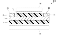
- metal plates (first metal plate 2X, second metal plate 2Y) are joined to both sides (front and back surfaces) of the inorganic porous layer 4.
- one inorganic porous layer 4 is connected to two metal plates (first metal plate 2X, second metal plate 2Y) facing each other at intervals.
- the composite member 410 can be suitably used as a partition plate arranged between two devices.
- the first metal plate 2X and the second metal plate 2Y can dissipate heat generated from each device.
- the heat of one device (for example, the device arranged on the first metal plate 2X side) is applied to the other device (device arranged on the second metal plate 2Y side). Can be suppressed.
- the composite member 510 (fifth embodiment) shown in FIG. 10 is a modified example of the composite member 10c (see FIG. 6).
- end portions (both ends) 2a of the linear metal 2 in the longitudinal direction are exposed. That is, in the composite member 510, the inorganic porous layer 4 is bonded to the intermediate portion excluding the end portion 2a of the metal 2.
- the composite member 510 can be suitably used as a heat conductive member that transfers the heat of one end 2a to the other end 2a. Further, since the composite member 510 is provided with the inorganic porous layer 4 in the intermediate portion, it is possible to suppress heat from being applied to the parts existing around the intermediate portion.
- the characteristics of the composite member 510 an inorganic porous layer is bonded to an intermediate portion excluding the longitudinal end portion of the metal) can also be applied to the composite members 10, 10a and 10b.
- the composite member 610 (sixth embodiment) shown in FIG. 11 is a modified example of the composite member 310 (see FIG. 8).
- the inorganic porous layer 4 is joined to the entire surface of one surface (back surface) of the flat plate-shaped metal 2, and the end portions (both ends) of the metal 2 in the longitudinal direction on the other surface (front surface). ) It is joined to the intermediate part except 2a.
- the composite member 610 can be suitably used as a heat conductive member that transfers the heat of one end 2a to the other end 2a.
- the inorganic porous layer 4 may be joined to an intermediate portion of both sides of the metal 2 except for the end portion 2a of the metal 2. Further, the characteristics of the composite member 610 (an inorganic porous layer is bonded to an intermediate portion excluding the longitudinal end portion of the metal) can also be applied to the composite member 210.
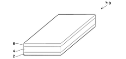
- the composite member 710 (7th embodiment) shown in FIG. 12 is a modified example of the composite member 210 (see FIG. 7).
- the coating layer 6 is provided on the surface of the inorganic porous layer 4 (the surface opposite to the surface on which the metal 2 is provided).
- the coating layer 6 was formed by forming the inorganic porous layer 4 on the surface of the metal 2, then applying a raw material slurry to the surface of the inorganic porous layer 4 using a spray, drying and firing.
- the raw material slurry used for forming the coating layer 6 was plate-shaped alumina particles (average particle diameter 6 ⁇ m), titania particles (average particle diameter 0.25 ⁇ m), and alumina sol (alumina amount 1.1% by mass).
- the raw material slurry used for molding the coating layer 6 is obtained by removing the alumina fibers from the raw material slurry used for forming the inorganic porous layer 4. Since the coating layer 6 has a denser structure than the inorganic porous layer 4, it functions as a reinforcing material for the inorganic porous layer 4.
- the material of the coating layer 6 can be appropriately changed to, for example, the above-mentioned material depending on the purpose.
- the composite member 810 (8th embodiment) shown in FIG. 13 is a modified example of the composite member 710 (see FIG. 12).
- the coating layer 6 is intermittently (partially) provided on the surface of the inorganic porous layer 4 in the longitudinal direction of the composite member 810.
- the coating layer 6 is separated from the inorganic porous layer 4 by intermittently providing the coating layer 6 on the surface of the inorganic porous layer 4.
- the characteristics of the composite members 710 and 810 (the coating layer is provided on the surface of the inorganic porous layer) can also be applied to the composite members 10, 10a to 10c, 210, 310, 510 and 610.
- heat conduction member An example of using the above-mentioned composite member (heat conductive member 910) will be described with reference to FIG. Although the heat conductive member 910 uses the composite member 610 (see FIG. 11), other composite members described above may be used instead of the composite member 610.
- the inorganic porous layer 4 is bonded to the entire back surface of the metal 2 and to an intermediate portion of the surface of the metal 2 (a portion excluding the end portion 2a in the longitudinal direction). That is, on the surface of the metal 2, the inorganic porous layer 4 is not bonded to the end portion 2.
- a heat generating portion 20 and a heat radiating portion 22 are joined to the end portion 2a.
- the heat received by the heat generating unit 20 moves through the metal 2 and is dissipated by the heat radiating unit 22 (heat sink). Since the inorganic porous layer 4 is bonded to the front surface (intermediate portion) and the back surface of the heat conductive member 910, heat dissipation from the metal 2 is suppressed between the heat generating portion 20 and the heat radiating portion 22. Therefore, it is possible to suppress heat from being applied to the equipment provided in the space 30 near the front surface of the heat conductive member 910 and the space 32 near the back surface of the heat conductive member 910.
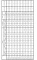
- the blending amounts of ceramic fibers (alumina fibers,glasse fibers), plate-shaped ceramic particles (plate-shaped alumina particles, plate-shaped mica), titania particles and zirconia particles, and the size of the acrylic resin are shown in FIGS. 15 and 16.
- the ceramic fibers, plate-shaped ceramic particles, titania particles, and zirconia particles were blended so as to have a total of 100% by mass, and further, 10% by mass of alumina sol (amount of alumina contained in the alumina sol) was added. 1% by mass) and 40% by mass of acrylic resin were added, and the slurry viscosity was adjusted with ethanol to prepare a raw material slurry.
- sample 9 does not use plate-shaped ceramic particles, and samples 1 to 11, 14, 16 and 17 do not use zirconia particles.
- the raw material slurry is applied to SUS430 (SUS plate, SUS tube), and for samples 13 and 14, the raw material slurry is applied to copper (copper plate, copper tube), and the atmosphere atmosphere 200. After drying at ° C. for 1 hour, it was calcined at an air atmosphere of 800 ° C. for 3 hours. The number of times the raw material slurry was applied (the number of times the metal plate and the metal tube were immersed) in each sample was adjusted so that an inorganic porous layer of about 1.2 mm was formed on the metal surface (inner surface in the case of a metal tube).
- the amount of alumina component (ceramic fiber, plate-shaped ceramic particles) and titania component the effect of pore diameter on the appearance of the inorganic porous layer after firing (presence or absence of cracks, peeling, etc.), and resistance.
- the heat insulating property of the inorganic porous layer has not been evaluated for the purpose of confirming the heating vibration property.
- the appearance of the sample after firing was evaluated.
- the appearance was evaluated with a sample in which an inorganic porous layer was formed on a metal plate.
- the presence or absence of cracks and peeling was visually observed.
- FIG. 15 “ ⁇ ” is attached to the sample in which crack and peeling did not occur, “ ⁇ ” is attached to the sample in which one of crack and peeling occurred, and “ ⁇ ” was attached to the sample in which both crack and peeling occurred.
- "X" is attached.
- Porosity was measured for Samples 1 to 17.
- the porosity was measured by preparing a bulk body of the inorganic porous layer without forming the inorganic porous layer on the metal plate.
- the porosity is the total pore volume (unit: cm 3 / g) measured in accordance with JIS R1655 (a molded body pore size distribution test method by the mercury intrusion method of fine ceramics) using a mercury porosity, and a gas substitution formula. It was calculated from the following formula (2) using the apparent density (unit: g / cm 3 ) measured by a density measuring meter (Accupic 1330 manufactured by Micromeritix).
- the pore diameters of samples 1 to 17 were measured.
- the pore diameter is measured using a mercury porosimeter in accordance with JIS R1655 (a molded body pore diameter distribution test method by the mercury intrusion method of fine ceramics), and the median diameter is calculated from the obtained pore diameter distribution map. rice field.
- FIG. 15 shows the measured pore diameter (median diameter).
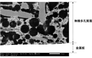
- FIG. 17 shows an SEM photograph of sample 6. As shown in FIG. 17, it was confirmed that the sample 6 had pores of about 10 ⁇ m in the inorganic porous layer.
- a heating vibration test was performed on the samples 1 to 17.
- the heating thermal vibration test was performed on a sample in which an inorganic porous layer was formed on the inner surface of a metal tube. Specifically, the outer surface of a pipe (made of SUS430, made of copper) having an inner diameter of ⁇ 55 mm, an outer diameter of ⁇ 62 mm (thickness 3.5 mm), and a length of 80 mm is immersed in the raw material slurry with the outer surface masked, and the inorganic porous layer is placed on the inner wall of the pipe. was applied to. Then, each sample was prepared by drying at 200 ° C. and calcining at 800 ° C.
- the sample was attached to the heating vibration test device, and the combustion gas of propane was circulated in the pipe for 5 minutes from the heating vibration test device, and then the normal temperature air gas was circulated for 5 minutes.
- the combustion gas was adjusted so that the gas temperature at the end face on the inflow side of the pipe was 900 ° C. at the maximum and the gas flow rate was 2.0 Nm 3 / min.
- vibrations in the longitudinal direction (longitudinal direction) and the radial direction (direction orthogonal to the longitudinal direction) were applied to the pipe.
- the vibration conditions were 100 Hz and 30 G, and vibration was applied for 50 hours.
- the ratio (mass%) of the alumina component and the titania component was measured using the bulk body.
- the amounts of aluminum and titanium were measured using an ICP emission spectrometer (PS3520UV-DD, manufactured by Hitachi High-Tech Science Co., Ltd.).
- Figures 15 and 16 show the results of oxide conversion (Al 2 O 3 , TiO 2 ) of the amounts of aluminum and titanium.
- the coefficient of thermal expansion of the inorganic porous layer and the metal (metal plate) was measured.
- the sample for measuring the coefficient of thermal expansion of the inorganic porous layer was prepared by molding the above-mentioned raw material slurry into a bulk body having a size of 4 mm ⁇ 3 mm ⁇ 20 mm and then firing the bulk body at 800 ° C.
- As the sample for measuring the coefficient of thermal expansion of the metal a sample having a size of 4 mm ⁇ 3 mm ⁇ 20 mm was used.
- the measurement sample was measured using a thermal expansion meter in accordance with JIS R1618 (measurement method of thermal expansion by thermomechanical analysis of fine ceramics).
- FIG. 16 shows the result of the coefficient of thermal expansion.
- the thermal conductivity of the inorganic porous layer and the metal was measured. Thermal conductivity was also measured using separate bulk bodies for the inorganic porous layer and the metal plate. The thermal conductivity was calculated by multiplying the thermal diffusivity, the specific heat capacity and the bulk density. For the heat diffusion rate, a laser flash method heat constant measuring device is used, and for the specific heat capacity, a DSC (differential scanning calorimetry) is used. Method) was measured at room temperature. For the bulk density of the metal plate, the weight of a bulk body having a diameter of 10 mm and a thickness of 1 mm was measured, and the value obtained by dividing the weight by the volume was taken as the bulk density (unit: g / cm 3 ).
- the bulk density (unit: g / cm 3 ) of the inorganic porous layer was calculated from the following formula (3).
- the thermal diffusivity is obtained by molding the above-mentioned raw material slurry into a bulk body having a diameter of 10 mm ⁇ 1 mm
- the specific heat capacity is obtained by molding the above-mentioned raw material slurry into a bulk body having a diameter of 5 mm ⁇ a thickness of 1 mm, and then each bulk body is 800.
- the proportion of the alumina component in the sample 15 is less than 15% by mass, it is presumed that the bonding force between the ceramics (particles, fibers) is reduced and cracks are generated in the inorganic porous layer. Further, since the proportion of the titania component in the sample 16 is less than 45% by mass, it is presumed that the bonding force between the ceramics is lowered and cracks are generated in the inorganic porous layer. Further, in the sample 16, the content of the titania component (titania particles) having a high coefficient of thermal expansion is low, and the ratio of the coefficient of thermal expansion to the metal ( ⁇ 1 / ⁇ 2) is small (less than 0.5).
- the inorganic porous layer was separated from the metal based on the difference in thermal expansion. From the above, regardless of the type of ceramic fiber (alumina fiber, mullite fiber) and the type of plate-shaped ceramic particles (plate-shaped alumina particle, plate-shaped mica), 15% by mass or more of alumina component and 45% by mass or more of titania component. It was confirmed that the inorganic porous layer containing the above was less likely to cause deterioration such as cracks and peeling after firing.
Abstract
複合部材は、金属の表面に無機多孔質層が設けられている。この複合部材では、無機多孔質層は、セラミック繊維を含み、15質量%以上のアルミナ成分と45質量%以上のチタニア成分によって構成されており、気孔径が1μm以上30μm以下である。
Description
本出願は、2020年7月13日に出願された日本国特許出願第2020-120259号に基づく優先権を主張する。その出願の全ての内容は、この明細書中に参照により援用されている。本明細書は、複合部材に関する技術を開示する。
金属の表面に無機質の保護層を設け、金属と無機材料の複合部材を構成することがある。例えば、特開2018-33245号公報(以下、特許文献1と称する)は、主に自動車のエンジン部品(金属)に耐熱性を付与するため、金属表面に無機保護層を被覆している。特許文献1では、金属と無機保護層の熱膨張率の相違に伴って無機保護層が金属から剥離することを防止するため、金属表面に非晶性無機材層(具体的には、硼珪酸ガラス)を形成し、非晶性無機材層の表面に非酸化物系セラミック(具体的には、炭化ケイ素)を形成している。すなわち、特許文献1では、金属と、保護層としての機能を発揮する機能層(炭化ケイ素)との間に、両者の熱膨張率差を緩和するための緩和層(硼珪酸ガラス)を設けている。特許文献1は、非晶質の緩和層を設けることにより、金属と機能層の密着性を向上させている。
上記したように、特許文献1は、金属と機能層の間に非晶質の緩和層を設ける。そのため、機能層を形成する際、緩和層の軟化点を超えない温度で機能層を形成することが必要である。換言すると、機能層として利用可能な材料が、緩和層の軟化点を超えない条件で成膜可能な材料に制限される。そのため、特許文献1の複合部材は、使用し得る材料(緩和層、機能層)の自由度が低い。また、特許文献1の複合部材は、非晶質の緩和層を用いているので、耐熱性の向上も限定的である。そのため、複合材料の分野においては、継続的な改善が必要とされている。本明細書は、従来にない新規な複合部材を提供することを目的とする。
本明細書で開示する複合部材は、金属の表面に無機多孔質層が設けられていてよい。また、無機多孔質層は、セラミック繊維を含み、15質量%以上のアルミナ成分と45質量%以上のチタニア成分によって構成されており、気孔径が1μm以上30μm以下であってよい。
本明細書で開示する複合材料は、金属の表面に無機多孔質層が設けられている。無機多孔質体は、典型的に、無機多孔質体を介した内外の環境を「断つ」能力が高い。そのため、上記複合部材は、外部環境が金属に影響を及ぼすことを抑制し、あるいは、外部環境に金属の影響が及ぶことを抑制し、高い断熱性、高い遮音性(吸音性)等を実現することができる。また、上記複合部材は、無機多孔質層によって、吸着性、吸湿性等、外部環境の物質(異物、水分等)が金属に接することを抑制することもできる。あるいは、上記複合部材は、無機多孔質層を利用して、触媒等を金属表面に担持させることもできる。なお、本明細書でいう「多孔質」とは、無機多孔質層の気孔率(空隙率)が45体積%以上であることを意味する。
本明細書で開示する複合部材は、例えば、高温環境下において好適に用いることができる。一例として、複合部材は、エキゾーストマニホールド、エキゾーストパイプ(排気管)といった自動車の排気系を構成する部材として好適に用いることができる。また、本明細書で開示する複合部材は、例えば、熱源で生じた熱を熱源から離れた位置に存在する部品(例えば放熱板)に伝達する熱伝導部材として好適に用いることができる。あるいは、複数の機器の間に複合部材を配置し、一方の機器から生じる熱が他方の機器に加わることを防止する仕切り板として好適に用いることもできる。
無機多孔質層は、セラミック繊維を含んでいてもよい。セラミック繊維は、無機多孔質層内において、骨材、補強材として機能し得る。すなわち、セラミック繊維は、無機多孔質層の強度を向上させ、さらに、製造工程において無機多孔質層が収縮することを抑制する。無機多孔質層を形成する際の原料中のセラミック繊維の長さは、50μm以上200μm以下であってよい。また、セラミック繊維の直径(平均径)は、1~20μmであってよい。無機多孔質層を形成する際の原料に占めるセラミック繊維の体積率は、5体積%以上25体積%以下であってよい。無機多孔質層の原料が5体積%以上のセラミック繊維を含むことにより、無機多孔質層の製造過程(焼成工程)において無機多孔質層内のセラミック粒子の収縮を十分に抑制することができる。また、原料中のセラミック繊維の体積率を25体積%以下とすることにより、無機多孔質層内の伝熱経路を分断することができ、金属への伝熱を好適に抑制し得る。
また、セラミック繊維は、金属と無機多孔質層の熱膨張率差の影響を吸収することができる。具体的には、無機多孔質層が金属の変形(熱膨張,熱収縮)に追従して変形することができるので、金属から無機多孔質層が剥離することを防止することができる。すなわち、金属と無機多孔質層の密着性が向上する。また、複合材料を内燃機関の排気管として用いると、無機多孔質層によって、排気ガスが金属(金属管)に接することを抑制し、金属管が劣化することを抑制することもできる。
セラミック繊維は、無機多孔質層内において、骨材、補強材として機能し得る。すなわち、セラミック繊維は、無機多孔質層の強度を向上させ、さらに、製造工程において無機多孔質層が収縮することを抑制する。セラミック繊維の長さは、50μm以上200μm以下であってよい。また、セラミック繊維の直径(平均径)は、1~20μmであってよい。セラミック繊維は、無機多孔質層の断面をSEM観察することにより確認することができる。セラミック繊維は、SEM画像において略円形である。すなわち、SEM画像には、セラミック繊維の径方向断面が現れる。また、セラミック繊維の材料が無機多孔質層を構成する他の材料と異なる場合、EDS分析を行うことによってセラミック繊維を判別(確認)することもできる。無機多孔質層内を形成する際の原料に占めるセラミック繊維の体積率は、5体積%以上25体積%以下であってよい。無機多孔質層の原料が5体積%以上のセラミック繊維を含むことにより、無機多孔質層の製造過程(焼成工程)において無機多孔質層内のセラミック粒子の収縮を十分に抑制することができる。また、原料中のセラミック繊維の体積率を25体積%以下(すなわち、無機多孔質層内のセラミック繊維の体積率が25体積%以下)とすることにより、無機多孔質層内の伝熱経路を分断することができ、金属への伝熱を好適に抑制し得る。なお、セラミック繊維の材料が無機多孔質層を構成する他の材料と異なる場合、EDS分析の結果を画像処理することにより、無機多孔質層内のセラミック繊維の割合(体積率)を測定することができる。
なお、セラミック繊維の材料として、アルミナ(Al2O3)、スピネル(MgAl2O4)、チタニア(TiO2)、ジルコニア(ZrO2)、マグネシア(MgO)、ムライト(Al6O13Si2)、コージェライト(MgO・Al2O3・SiO2)、イットリア(Y2O3)、ステアタイト(MgO・SiO2)、フォルステライト(2MgO・SiO2)、ランタンアルミネート(LaAlO3)、ストロンチウムチタネート(SrTiO3)等を用いることができる。また、無機多孔質層内に、上記材料で形成された一種または複数種のセラミック繊維が含まれていてよい。
無機多孔質層は、15質量%以上のアルミナ成分と45質量%以上のチタニア成分によって構成されていてよい。このような無機多孔質層は、無機多孔質層自体の融点が高くなり、複合部材の外部環境が高温になっても形状を維持することができる。
無機多孔質層の気孔率は、45体積%以上90体積%以下であってよい。気孔率が45体積%以上であれば、断熱性、遮音性、吸着性、吸湿性等、多孔質であることの機能を十分に発揮し得る。また、気孔率が45体積%以上であれば、無機多孔質層内の空隙を利用して、触媒を十分に担持させることもできる。気孔率が90体積%以下であれば、十分な強度を確保することができる。なお、無機多孔質層の気孔率は、55体積%以上であってよく、60体積%以上であってよく、65体積%以上であってもよい。さらに、無機多孔質層の気孔率は、85体積%以下であってよく、80体積%以下であってよく、70体積%以下であってよく、65体積%以下であってよく、60体積%以下であってもよい。また、無機多孔質層が多層構造又は傾斜構造の場合、無機多孔質層の気孔率は、全体として45体積%以上90体積%以下であればよく、厚み方向で気孔率が異なっていてもよい。この場合、部分的に、気孔率が45体積%未満の部分、あるいは、気孔率が90体積%超の部分が存在していてよい。
無機多孔質層の気孔径は、1μm以上30μm以下であってよい。気孔径が1μm以上であれば、無機多孔質層の骨格(網目状骨格)が十分な太さとなり、無機多孔質層の強度を確保することができる。また、気孔径が30μm以下であれば、無機多孔質層の組織(骨格、骨格を結合する物質等)が不均一になることが抑制され、無機多孔質層に局所的な脆弱部が生じることを抑制することができる。なお、「気孔径」は、水銀ポロシメーターを用いてJIS R1655(ファインセラミックスの水銀圧入法による成形体気孔径分布試験方法)に準拠して測定することができる。本明細書でいう「気孔径」は、上記測定により得られた細孔径分布図から求めたメディアン径を意味する。なお、気孔径は、2μm以上であってよく、5μm以上であってよく、10μm以上であってよく、15μm以上であってよく、20μm以上であってもよい。また、気孔径は、25μm以下であってよく、20μm以下であってよく、15μm以下であってよく、10μm以下であってよく、5μm以下であってもよい。
無機多孔質層の熱膨張係数をα1とし、金属の熱膨張係数をα2としたときに、下記式(1)を満足していてよい。無機多孔質層が金属から剥離する現象を、より確実に防止することができる。
式1:0.5<α1/α2<1.2
式1:0.5<α1/α2<1.2
無機多孔質層は、扁平板状の板状セラミック粒子を含んでいてよい。板状セラミック粒子は、断面をSEMで観察したときのアスペクト比が10以上60以下であってよい。無機多孔質層に含まれる板状セラミック粒子の断面のアスペクト比は、無機多孔質層の断面をSEM観察することにより確認することができる。板状セラミック粒子は、SEMにおいて棒状に現れる。板状セラミック粒子は、無機多孔質層自体の強度(機械的強度)が低下することを抑制することができる。なお、断面のアスペクト比が10以上60以下の板状セラミック粒子は、例えば、原料として断面のアスペクト比が60以上100以下の板状セラミック粒子を用いることにより、無機多孔質層の製造過程においてアスペクト比が小さくなり、結果として無機多孔質内に残存する。原料として断面のアスペクト比が60以上100以下の板状セラミック粒子を用いて無機多孔質層を形成すると、セラミック粒子の焼結を適度に抑制することができ、製造後(焼成後)に無機多孔質層が硬くなりすぎる(ヤング率が高くなりすぎる)ことを抑制することができる。例えば、複合材料を内燃機関の排気管として用いる場合、無機多孔質層が適度な靭性を有する(ヤング率が高すぎない)ことにより、内燃機関の始動直後の熱衝撃(低温状態の無機多孔質に高温の排気ガスが接触すること)によって無機多孔質層が破損する(クラック等が生じる)ことを抑制することができる。また、板状セラミック粒子によって無機多孔質層の強度が維持されるので、排気管の振動、あるいは、排気ガスのガス流によって無機多孔質層が破損することを抑制することができる。
無機多孔質層に、0.1μm以上10μm以下の粒状粒子が含まれていてよい。無機多孔質層を成形(焼成)する際、セラミック繊維等の骨材同士が粒状粒子を介して結合され、高強度の無機多孔質層が得られる。また、無機多孔質層の厚みは、1mm以上であってよい。これにより、上記した機能(断熱性、遮音性、吸着性、吸湿性等)を十分に発揮することができる。なお、無機多孔質層がセラミック繊維及び板状セラミック粒子を含んでいると、1mm以上の無機多孔質層を実現することができる。すなわち、無機多孔質層が、成形する過程(例えば、焼成工程)において収縮が起こり難い材料(板状セラミック粒子、セラミック繊維)を含むことにより、無機多孔質層を1mm以上に成形することができる。例えば、無機多孔質層がセラミック繊維等を含んでいない場合、成形する過程で無機多孔質層が収縮し、クラック等が発生する、そのため、無機多孔質層がセラミック繊維等を含んでいない場合、無機多孔質層を1mm以上という厚膜に形成することが困難である。
上記したように、無機多孔質層は、15質量%以上のアルミナ(Al2O3)成分と、45質量%以上のチタニア(TiO2)成分によって構成されている。なお、無機多孔質層に含まれるアルミナ成分は、25質量%以上であってよく、30質量%以上であってよく、40質量%以上であってもよい。
無機多孔質層は、金属表面を被覆し、金属を外部環境から保護してよい。なお、「外部環境」とは、無機多孔質層を介して金属の反対側の空間のことを意味する。すなわち、複合材料が上記したような自動車の排気系を構成する部材の場合、「外部環境」は、エキゾーストマニホールド、エキゾーストパイプ等の内部空間に相当する。あるいは、無機多孔質層は、金属表面を被覆し、複合部材の外部環境に存在する部品を、金属の熱から保護(断熱)してよい。また、無機多孔質層は、間隔をあけて対向する2個の金属(例えば金属板)の双方の表面を被覆していてもよい。換言すると、1個の無機多孔質層の両面に、金属板(第1金属板,第2金属板)が接合されていてもよい。第1金属板側に配置されている第1機器から生じる熱が第2金属板側に配置されている第2機器に加わることを防止することができるとともに、第1金属板によって、第1機器が生じた熱を放熱することができる。
上記したように、複合部材は、無機多孔質層によって、金属と外部環境が互いに熱の影響を及ぼし合うことを抑制する。また、無機多孔質層によって、複数の機器が配置される空間を分離し、分離された空間同士が熱の影響を及ぼし合うことを抑制する。そのため、金属と無機多孔質層は、熱伝導率の差が大きいことが好ましい。具体的には、金属の熱伝導率は、無機多孔質層の熱伝導率の100倍以上であってよい。なお、金属の熱伝導率は、無機多孔質層の熱伝導率の150倍以上であってよく、無機多孔質層の熱伝導率の200倍以上であってよく、無機多孔質層の熱伝導率の250倍以上であってよく、無機多孔質層の熱伝導率の300倍以上であってもよい。
金属の熱伝導率は、10W/mK以上400W/mK以下であってよい。なお、金属の熱伝導率は、25W/mK以上であってよく、50W/mK以上であってよく、100W/mK以上であってよく、150W/mK以上であってよく、200W/mK以上であってよく、250W/mK以上であってよく、300W/mK以上であってよく、380W/mK以上であってもよい。また、金属の熱伝導率は、350W/mK以下であってよく、300W/mK以下であってよく、250W/mK以下であってよく、200W/mK以下であってよく、150W/mK以下であってもよい。
無機多孔質層の熱伝導率は、0.05W/mK以上3W/mK以下であってよい。なお、無機多孔質層の熱伝導率は、0.1W/mK以上であってよく、0.2W/mK以上であってよく、0.3W/mK以上であってよく、0.5W/mK以上であってよく、0.7W/mK以上であってよく、1W/mK以上であってよく、1.5W/mK以上であってよく、2W/mK以上であってもよい。また、無機多孔質層の熱伝導率は、2.5W/mK以下であってよく、2.0W/mK以下であってよく、1.5W/mK以下であってよく、1W/mK以下であってよく、0.5W/mK以下であってよく、0.3W/mK以下であってよく、0.25W/mK以下であってもよい。
金属の形状は、特に限定されないが、管状(筒状)、線状(ワイヤー状)、板状(シート状)であってよい。管状金属の場合、無機多孔質層は、管状金属の内周面、及び/又は、外周面を被覆していてよい。線状の金属は、典型的に中実構造である。そのため、線状金属の場合、無機多孔質層は、線状金属の外周面を被覆していてよい。板状金属の場合、無機多孔質層は、板状金属の露出面全体を被覆していてもよいし、厚み方向端部の面(表面、及び/又は、裏面)を被覆していてもよいし、幅方向端部の面(側面)を被覆していてもよいし、長さ方向端部の面を被覆していてもよい。また、板状金属の場合、無機多孔質層は、第1の板状金属(第1金属板)の表面と第2の板状金属(第2金属板)の裏面の双方を被覆していてよい。
金属が管状の場合、金属管は、単管であってもよいし、多重管(例えば二重管)であってもよい。金属管は、直線状であってもよく、全体(または一部)が曲線状であってもよく、中間部分がテーパー状であってもよく、また、分岐管であってもよい。無機多孔質層は、単管の場合は金属管の内面、多重管の場合は最も内側に配置されている金属管の内面に設けられていてよい。なお、無機多孔質層は、金属管内面の全面を被覆していてもよいし、金属管内面の一部を被覆していてもよい。例えば、無機多孔質層は、金属管の端部(一端または両端)を除く部分を被覆していてよい。
無機多孔質層は、金属表面の全面を被覆していてもよいし、金属表面の一部を被覆していてもよい。例えば、無機多孔質層が管状金属,線状金属を被覆している場合、無機多孔質層は、金属の端部(一端または両端)を除く部分を被覆していてよい。また、無機多孔質層が管状金属の内周面及び外周面を被覆している場合、内周面は一端から他端まで無機多孔質層が被覆され(すなわち、全面被覆)、外周面は端部を除く部分が被覆されている等、内周面と外周面において無機多孔質層で被覆されている範囲が異なっていてもよい。また、無機多孔質層が板状金属を被覆している場合(例えば、厚み方向端部の面:表裏面)、無機多孔質層は、表裏面の一部(例えば、長手方向の一端または両端部)を除く部分を被覆していてよい。あるいは、無機多孔質層は、裏面については全体を被覆し、表面については例えば両端部を除く部分を被覆している等、表裏面で被覆する範囲が異なっていてもよい。
また、無機多孔質層は、厚み方向において、均一の材料で構成されていてよい。すなわち、無機多孔質層は単層であってよい。また、無機多孔質層は、厚み方向において、組成の異なる複数の層で構成されていてもよい。すなわち、無機多孔質層は、複数の層が積層した多層構造であってよい。あるいは、無機多孔質層は、厚み方向において、組成が除々に変化する傾斜構造であってもよい。無機多孔質層が単層の場合、複合部材の製造(金属表面に無機多孔質層を成形する工程)を容易に行うことができる。無機多孔質層が多層又は傾斜構造の場合、厚み方向において、無機多孔質層の特性を変化させることができる。無機多孔質層の構造(単層、多層、傾斜構造)については、必要に応じて適宜選択することができる。
無機多孔質層の厚みは、使用目的(要求性能)に依るが、1mm以上であってよい。無機多孔質層の厚みが1mm以上であれば、断熱性、遮音性、吸着性、吸湿性等、多孔質であることの機能を十分に発揮し得る。なお、セラミック繊維等が用いられていない無機多孔質層の場合、製造過程(例えば焼成工程)において収縮するため、厚みを1mm以上に維持することが困難である。セラミック繊維等を含んでいれば、製造過程における収縮が抑制され、1mm以上の厚みを維持することができる。なお、無機多孔質層の厚みが厚すぎると、コスト(製造コスト、材料コスト)に見合う特性の向上が得られにくくなる。そのため、特に限定されないが、無機多孔質層の厚みは、30mm以下であってよく、20mm以下であってよく、15mm以下であってよく、10mm以下であってよく、5mm以下であってよい。
無機多孔質層は、セラミック粒子(粒状粒子)、板状セラミック粒子、セラミック繊維のうちの1以上の材料により構成されている。なお、セラミック粒子、板状セラミック粒子及びセラミック繊維は、構成成分として、アルミナ、及び/又は、チタニアを含んでいてよい。換言すると、アルミナ、及び/又は、チタニアによって、セラミック粒子、板状セラミック粒子、セラミック繊維が形成されていてよい。すなわち、無機多孔質層は、構成材料(構成物質)全体で、15質量%以上のアルミナ成分と45質量%以上のチタニア成分を含んでいればよい。但し、無機多孔質層は、構成成分は任意(アルミナ成分、チタニア成分を含んでいてもよいし、含んでいなくてもよい)であるが、少なくともセラミック繊維を含んでいることが好ましい。
セラミック粒子は、板状セラミック粒子,セラミック繊維等の無機多孔質層の骨格をなす骨材同士を接合する接合材として用いられてよい。セラミック粒子は、0.1μm以上10μm以下の粒状粒子であってよい。なお、セラミック粒子は、製造過程(例えば焼成工程)において、焼結等により粒径が大きくなってもよい。すなわち、無機多孔質層を製造する原料として、セラミック粒子は、0.1μm以上10μm以下(焼成前の平均粒径)の粒状粒子であってよい。なお、セラミック粒子は、0.5μm以上であってよく、5μm以下であってもよい。セラミック粒子の材料として、例えば金属酸化物を利用してよい。金属酸化物の一例として、アルミナ(Al2O3)、スピネル(MgAl2O4)、チタニア(TiO2)、ジルコニア(ZrO2)、マグネシア(MgO)、ムライト(Al6O13Si2)、コージェライト(MgO・Al2O3・SiO2)、イットリア(Y2O3)、ステアタイト(MgO・SiO2)、フォルステライト(2MgO・SiO2)、ランタンアルミネート(LaAlO3)、ストロンチウムチタネート(SrTiO3)等が挙げられる。これらの金属酸化物は、高い耐蝕性を有する。そのため、セラミック粒子の材料として上記金属酸化物を用いることにより、無機多孔質層を、例えば自動車の排気系の部品(排気管等)の保護層として好適に適用することができる。
板状セラミックは、無機多孔質層内において、骨材、補強材として機能し得る。すなわち、板状セラミックは、セラミック繊維と同様に、無機多孔質層の強度を向上させ、さらに、製造工程において無機多孔質層が収縮することを抑制する。なお、板状セラミック粒子を用いることにより、無機多孔質層内の伝熱経路を分断することができる。そのため、複合部材が高温環境で用いられる場合(無機多孔質層が金属を断熱する目的で用いられる場合)、骨材としてセラミック繊維のみを用いる形態と比較して、断熱性を向上させることができる。
扁平板状の板状セラミック粒子は、表面形状(厚み方向から観察した形状)は特に限定されず、例えば、矩形等の多角形、略円形、曲線及び/又は直線で囲まれた不定形であってよく、断面を観察したときの長手方向サイズが5μm以上100μm以下であってよい。長手方向サイズが5μm以上であれば、セラミック粒子の過剰な焼結を抑制することができる。長手方向サイズが100μm以下であれば、上述したように無機多孔質層内の伝熱経路を分断する効果が得られ、高温環境で用いる複合部材に好適に適用し得る。
また、板状セラミック粒子は、断面のアスペクト比が10以上60以下であってよい。断面のアスペクト比が10以上であればセラミック粒子の焼結を良好に抑制することができ、熱衝撃に対して高い耐性が得られる。また、断面のアスペクト比が60以下であれば板状セラミック粒子自体の強度低下が抑制され、機械的衝撃(振動等)に対して高い耐性が得られる。その結果、複合部材が内燃機関の排気管である場合、排気管の振動、あるいは、排気ガスのガス流によって無機多孔質層が破損することを抑制することができる。なお、板状セラミック粒子の材料として、上記したセラミック粒子の材料として用いられる金属酸化物に加え、タルク(Mg3Si4O10(OH)2)、マイカ、カオリン等の鉱物・粘土、ガラス等を用いることもできる。
また、無機多孔質層を形成する際の原料に占める骨材、補強材(セラミック繊維,板状セラミック粒子等。以下、単に骨材と称する)の含有率は、15質量%以上55質量%以下であってよい。無機多孔質層の原料中の骨材の含有率が15質量%以上であれば、焼成工程における無機多孔質層の収縮を十分に抑制することができる。また、原料中の骨材の含有率が55質量%以下であれば、セラミック粒子によって骨材同士が良好に接合される。原料中の骨材の含有率は、20質量%以上であってよく、30質量%以上であってよく、50質量%以上であってよく、53質量%以上であってもよい。また、原料中の骨材の含有率は、53質量%以下であってよく、50質量%以下であってよく、30質量%以下であってよく、20質量%以下であってもよい。
上記したように、セラミック繊維及び板状セラミック粒子は、ともに無機多孔質層内において骨材、補強材として機能し得る。しかしながら、複合部材の作製後(焼成後)に無機多孔質層が収縮することを確実に抑制するため、骨材としてセラミック繊維と板状セラミック粒子の双方を用いる場合であっても、無機多孔質層を形成する際の原料中のセラミック繊維の含有量は、少なくとも5質量%以上であってよい。なお、原料中のセラミック繊維の含有量は、10質量%以上であってよく、20質量%以上であってよく、30質量%以上であってよく、40質量%以上であってよい。また、原料中のセラミック繊維の含有量は、50質量%以下であってよく、40質量%以下であってよく、30質量%以下であってよく、20質量%以下であってよく、10質量%以下であってもよい。
骨材としてセラミック繊維と板状セラミック粒子の双方を用いる場合、骨材全体に占める板状セラミック粒子の割合は、70質量%以下であってよい。すなわち、質量比で、骨材の少なくとも30質量%以上がセラミック繊維であってよい。骨材全体に占める板状セラミック粒子の割合は、67質量%以下であってよく、64質量%以下であってよく、63質量%以下であってよく、60質量%以下であってよく、50質量%以下であってもよい。なお、板状セラミック粒子は必ずしも骨材として必須ではない。また、骨材全体に占める板状セラミック粒子の割合は、40質量%以上であってよく、50質量%以上であってよく、60質量%以上であってよく、62質量%以上であってよく、63質量%以上であってよく、65質量%以上であってもよい。
なお、無機多孔質層を形成する際の原料に占める板状セラミック粒子の含有量は、5質量%以上35質量%以下であってよい。無機多孔質層の原料が5質量%以上の板状セラミック粒子を含むことにより、無機多孔質層の製造過程(焼成工程)において無機多孔質層内のセラミック粒子の収縮を十分に抑制することができる。また原料中の板状セラミック粒子の含有量を35質量%以下(すなわち、無機多孔質層内の板状セラミック粒子の割合を35質量%以下)とすることにより、無機多孔質層内の伝熱経路を分断することができ、金属への伝熱を好適に抑制し得る。原料中の板状セラミック粒子の含有量は、5質量%以上であってよく、10質量%以上であってよく、20質量%以上であってよく、30質量%以上であってよく、33質量%以上であってよい。また、原料中の板状セラミック粒子の含有量は、35質量%以下であってよく、33質量%以下であってよく、30質量%以下であってよく、20質量%以下であってよく、10質量%以下であってもよい。
なお、特に高温環境で用いられる複合部材においては、無機多孔質層に含まれるSiO2は、25質量%以下であってよい。無機多孔質層内に非晶質層が形成されることが抑制され、無機多孔質層の耐熱性(耐久性)が向上する。
無機多孔質層を形成する際、セラミック粒子、板状セラミック粒子、セラミック繊維の他に、バインダ、造孔材、溶媒を混合した原料を用いてよい。バインダとして、無機バインダを使用してよい。無機バインダの一例として、アルミナゾル、シリカゾル、チタニアゾル、ジルコニアゾル等が挙げられる。これらの無機バインダは、焼成後の無機多孔質層の強度を向上させることができる。造孔材として、高分子系造孔材、カーボン系粉等を使用してよい。具体的には、アクリル樹脂、メラミン樹脂、ポリエチレン粒子、ポリスチレン粒子、カーボンブラック粉末、黒鉛粉末等が挙げられる。造孔材は、目的に応じて種々の形状であってよく、例えば、球状、板状、繊維状等であってよい。造孔材の添加量、サイズ、形状等を選択することにより、無機多孔質層の気孔率、気孔サイズを調整することができる。溶媒は、他の原料に影響を及ぼすことなく原料の粘度を調整可能なものであればよく、例えば、水、エタノール、イソプロピルアルコール(IPA)等を使用することができる。
なお、上記した無機バインダも無機多孔質層の構成材料である。そのため、無機多孔質層を形成する際にアルミナゾル、チタニアゾル等を用いる場合、無機多孔質層は、無機バインダを含む構成材料全体で、15質量%以上のアルミナ成分と45質量%以上のチタニア成分を含んでいればよい。
無機多孔質層の組成及び原料は、保護する金属の種類に応じて調整する。本明細書で開示する複合部材では、特に限定されないが、金属として、SUS430,SUS429,SUS444等のステンレス鋼、鉄、鋳鉄、銅、ハステロイ、インコネル、コバール、ニッケル合金等を用いることができる。無機多孔質層の組成及び原料は、用いる金属の熱膨張係数に応じて調整してよい。具体的には、無機多孔質層の熱膨張係数をα1とし、金属の熱膨張係数をα2としたときに、下記式1を満足するように調整してよい。例えば、金属がSUS430の場合、熱膨張係数α1が6×10⁻⁶/K<α1<14×10-6/Kとなるように、より好ましくは、熱膨張係数α1が6×10-6/K<α1<11×10-6/Kとなるように、無機多孔質層の組成及び原料を調整してよい。また、金属が銅の場合、熱膨張係数α1が8.5×10-6/K<α1<20×10-6/Kとなるように、より好ましくは、熱膨張係数α1が8.5×10-6/K<α1<18×10-6/Kとなるように、無機多孔質層の組成及び原料を調整してよい。なお、「α1/α2」の値は、0.55以上であってよく、0.6以上であってよく、0.65以上であってよく、0.75以上であってよく、0.8以上であってもよい。また、「α1/α2」の値は、1.15以下であってよく、1.1以下であってよく、1.05以下であってよく1.0以下であってもよい。
式1:0.5<α1/α2<1.2
式1:0.5<α1/α2<1.2
本明細書で開示する複合部材では、金属表面(管状金属の場合、管内)に上記原料を塗布し、乾燥、焼成を経て金属表面に無機多孔質層を形成してよい。原料の塗布方法として、ディップコート、スピンコート、スプレーコート、スリットダイコート、溶射、エアロゾルデポジション(AD)法、印刷、刷毛塗り、コテ塗り、モールドキャスト成形等を用いることができる。なお、目的とする無機多孔質層の厚みが厚い場合、あるいは、無機多孔質層が多層構造の場合、原料の塗布、原料の乾燥を複数回繰り返し、目的とする厚み、あるいは、多層構造に調整してもよい。上記塗布方法は、後述する被覆層を形成する塗布方法として適用することもできる。
また、本明細書で開示する複合部材では、無機多孔質層の金属が設けられている面とは反対側の面に、被覆層が設けられていてもよい。すなわち、無機多孔質層が、金属と被覆層によって挟まれていてよい。なお、被覆層は、無機多孔質層の表面(金属が設けられている面と反対側の面)の全面に設けられていてもよいし、無機多孔質層の表面の一部に設けられていてもよい。被覆層を設けることにより、無機多孔質層を保護(補強)することができる。
被覆層の材料は、多孔質または緻密質なセラミックであってよい。被覆層で用いられる多孔質セラミックの一例として、ジルコニア(ZrO2),部分安定化ジルコニア,安定化ジルコニア等が挙げられる。また、イットリア安定化ジルコニア(ZrO2-Y2O3:YSZ)、YSZにGd2O3、Yb2O3、Er2O3等を添加した金属酸化物、ZrO2-HfO2-Y2O3、ZrO2-Y2O3-La2O3、ZrO2-HfO2-Y2O3-La2O3、HfO2-Y2O3、CeO2-Y2O3、Gd2Zr2O7、Sm2Zr2O7、LaMnAl11O19、YTa3O9、Y0.7La0.3Ta3O9、Y1.08Ta2.76Zr0.24O9、Y2Ti2O7、LaTa3O9、Yb2Si2O7、Y2Si2O7、Ti3O5等が挙げられる。被覆層で用いられる緻密質なセラミックの一例として、アルミナ、シリカ、ジルコニアなどが挙げられる。また、上述した無機多孔質層の構成材料からセラミック繊維,板状セラミック粒子を除去することにより、低気孔率(緻密質)となるため、被覆層として用いてもよい。被覆層として多孔質または緻密質セラミックを用いることにより、無機多孔質層が補強され、無機多孔質層が金属の表面から剥がれることを抑制することができる。なお、被覆層として緻密質なセラミックを用いると、例えば高温ガスが無機多孔質層を透過することを抑制したり、無機多孔質層内で高温ガスが滞留することを抑制することができる。また、被覆層として緻密質なセラミックを用いることにより、金属と外部環境を電気的に絶縁する効果が向上する。複合部材を排気管として用いる場合、例えば排気ガスが無機多孔質層を透過することを抑制したり、無機多孔質層内で排気ガスが滞留することを抑制することができる。その結果、排気ガスの熱が金属に伝熱することを抑制する効果が期待できる。
被覆層の材料は、多孔質または緻密質なガラスであってよい。被覆層として多孔質または緻密質ガラスを用いることによっても、無機多孔質層が補強され、無機多孔質層が金属の表面から剥がれることを抑制することができる。また、被覆層の材料は、金属(無機多孔質層によって保護される金属とは別部品)であってもよい。無機多孔質層の表面に金属層を設けることにより、外部からの輻射熱を反射することができ、金属(無機多孔質層によって保護される金属)に熱が加わることをさらに抑制することができる。
図1から図3を参照し、複合部材10について説明する。複合部材10は、SUS430製の管状の金属(金属管)2の内面に無機多孔質層4を備えている。無機多孔質層4は、金属2の内面に接合している(図1及び図2を参照)。複合部材10は、金属2の外面をマスキングした状態で、金属2を原料スラリーに浸漬し、乾燥、焼成を行って製造した。原料スラリーは、アルミナ繊維(平均繊維長140μm)と、板状アルミナ粒子(平均粒子径6μm)と、チタニア粒子(平均粒子径0.25μm)と、アルミナゾル(アルミナ量1.1質量%)と、アクリル樹脂と、エタノールを混合し、作成した。なお、原料スラリーは、粘度が2000mPa・sとなるように調整した。
金属2を上記原料スラリーに浸漬して金属2の内面に原料を塗布した後、金属2を乾燥機に投入し、200℃(大気雰囲気)で1時間乾燥させた。これにより、金属2の内面におよそ300μmの無機多孔質層が形成された。その後、金属2を上記原料スラリーに浸漬して乾燥する工程を3回繰り返し、金属2の内面に1.2mmの無機多孔質層を形成した。その後、金属2を電気炉内に配置し、800℃(大気雰囲気)で3時間焼成し、複合部材10を作成した。無機多孔質層4は、金属2の内面全体に形成された(図3を参照)。得られた複合部材10は、無機多孔質層4の気孔率が61体積%であり、熱膨張係数が7×10⁻⁶K-1であった。なお、図示は省略するが、複合部材10では、チタニア粒子が、金属2の表面(内面)と骨材(アルミナ繊維及び板状アルミナ粒子)の間に介在し、金属2の内面と骨材を接合していることが確認された。
図4から図6を参照し、複合部材10の変形例(複合部材10a、10b、10c)について説明する。なお、図4から図6は、複合部材10の図3(断面図)に相当する部分を示している。
図4に示すように、複合部材10aでは、無機多孔質層4が、金属2の内面及び外面に接合している。複合部材10aは、金属2にマスキングを施すことなく、複合部材10と実質的に同じ工程を経て製造した。無機多孔質層4は、金属2の内面及び外面の全体に形成された。
図5に示すように、複合部材10bでは、無機多孔質層4が、金属2の外面に接合している。複合部材10bは、金属2の内面をマスキングした状態で、複合部材10と実質的に同じ工程を経て製造した。無機多孔質層4は、金属2の外面の全体に形成された。
図6に示すように、複合部材10cは、金属2が線状(ライン状)であり、中心に孔が形成されていない(図1~図5を比較参照)。すなわち、複合部材10cでは、金属2が中実である。複合部材10cでは、無機多孔質層4が、金属2の外面に接合している。複合部材10cは、金属2にマスキングを施すことなく、複合部材10と実質的に同じ工程を経て製造した。無機多孔質層4は、金属2の内面及び外面の全体に形成された。
(第2~第8実施例)
以下、第2~第8実施例の複合部材(複合部材210~810)について説明する。複合部材210~810は、複合部材10(及び10a~10c)と比較して、金属の形状、無機多孔質層の形成位置または範囲、被覆層の有無が異なる。複合部材210~810は、マスキングを施す位置、無機多孔質層の形成条件、及び、無機多孔質層を形成した後の焼成条件等を目的に合わせて調整したが、実質的に複合部材10と同じ工程を経て製造した。以下の説明においては、複合部材10(及び10a~10c)と共通する特徴については説明を省略することがある。
以下、第2~第8実施例の複合部材(複合部材210~810)について説明する。複合部材210~810は、複合部材10(及び10a~10c)と比較して、金属の形状、無機多孔質層の形成位置または範囲、被覆層の有無が異なる。複合部材210~810は、マスキングを施す位置、無機多孔質層の形成条件、及び、無機多孔質層を形成した後の焼成条件等を目的に合わせて調整したが、実質的に複合部材10と同じ工程を経て製造した。以下の説明においては、複合部材10(及び10a~10c)と共通する特徴については説明を省略することがある。
図7に示す複合部材210(第2実施例)は、平板状の金属2の表面(厚み方向端面のうちの一方の面)に無機多孔質層4が接合している。図8に示す複合部材310(第3実施例)は、平板状の金属2の両面(厚み方向端面の双方の面)に無機多孔質層4が接合している。複合部材210,310は、後述する熱伝導部材の材料として好適に用いることができる。
図9に示す複合部材410(第4実施例)は、無機多孔質層4の両面(表裏面)に、金属板(第1金属板2X,第2金属板2Y)が接合している。換言すると、間隔をあけて対向する2個の金属板(第1金属板2X,第2金属板2Y)に、1個の無機多孔質層4が接続されている。複合部材410は、2個の機器の間に配置する仕切板として好適に用いることができる。第1金属板2X及び第2金属板2Yは、各機器から生じる熱を放熱することができる。また、無機多孔質層4は、一方の機器(例えば第1金属板2X側に配置されている機器)の熱が他方の機器(第2金属板2Y側に配置されている機器)に加わることを抑制することができる。
図10に示す複合部材510(第5実施例)は、複合部材10cの変形例である(図6を参照)。複合部材510は、線状の金属2の長手方向の端部(両端部)2aが露出している。すなわち、複合部材510は、金属2の端部2aを除く中間部分に無機多孔質層4が接合されている。複合部材510は、一方の端部2aの熱を他方の端部2aに伝達する熱伝導部材として好適に用いることができる。また、複合部材510は、中間部分に無機多孔質層4が設けられているので、中間部分の周囲に存在する部品に熱が加わることを抑制することができる。なお、複合部材510の特徴(金属の長手方向端部を除く中間部分に無機多孔質層が接合されている)は、複合部材10,10a及び10bに適用することもできる。
図11に示す複合部材610(第6実施例)は、複合部材310の変形例である(図8を参照)。複合部材610では、無機多孔質層4は、平板状の金属2の一方の面(裏面)の全面に接合されており、他方の面(表面)では金属2の長手方向の端部(両端部)2aを除く中間部分に接合されている。複合部材610は、複合部材510と同様に、一方の端部2aの熱を他方の端部2aに伝達する熱伝導部材として好適に用いることができる。なお、無機多孔質層4は、金属2の両面において金属2の端部2aを除く中間部分に接合されていてもよい。また、複合部材610の特徴(金属の長手方向端部を除く中間部分に無機多孔質層が接合されている)は、複合部材210に適用することもできる。
図12に示す複合部材710(第7実施例)は、複合部材210の変形例である(図7を参照)。複合部材710では、無機多孔質層4の表面(金属2が設けられている面とは反対側の面)に、被覆層6が設けられている。被覆層6は、金属2の表面に無機多孔質層4を形成した後、スプレーを用いて無機多孔質層4の表面に原料スラリーを塗布し、乾燥、焼成を経て成形した。被覆層6を成形するために用いた原料スラリーは、板状アルミナ粒子(平均粒子径6μm)と、チタニア粒子(平均粒子径0.25μm)と、アルミナゾル(アルミナ量1.1質量%)と、アクリル樹脂(平均粒子径8μm)と、エタノールを混合し、作成した。すなわち、被覆層6を成形するために用いた原料スラリーは、無機多孔質層4を形成するために用いた原料スラリーからアルミナ繊維を除去したものである。被覆層6は、無機多孔質層4と比較して緻密な構造を有しているので、無機多孔質層4の補強材として機能する。なお、被覆層6の材料は、目的に応じて、例えば上述した材料に適宜変更することができる。
図13に示す複合部材810(第8実施例)は、複合部材710の変形例である(図12を参照)。複合部材810では、被覆層6が、複合部材810の長手方向において、無機多孔質層4の表面に間欠的に(部分的に)設けられている。例えば、被覆層6と無機多孔質層4の熱膨張係数差が大きい場合、被覆層6を無機多孔質層4の表面に間欠的に設けることにより、被覆層6が無機多孔質層4から剥離することを抑制することができる。なお、複合部材710,810の特徴(無機多孔質層の表面に被覆層を設ける)は、複合部材10,10a~10c,210,310,510及び610に適用することもできる。
(熱伝導部材)
図14を参照し、上述した複合部材の使用例(熱伝導部材910)について説明する。なお、熱伝導部材910は、複合部材610(図11を参照)を用いているが、複合部材610に代えて、上述した他の複合部材を用いることもできる。熱伝導部材910では、無機多孔質層4は、金属2の裏面の全面に接合されているともに、金属2の表面の中間部分(長手方向の端部2aを除く部分)に接合されている。すなわち、金属2の表面については、端部2に無機多孔質層4が接合されていない。端部2aには発熱部20及び放熱部22が接合されている。発熱部20で受熱した熱は、金属2を移動し、放熱部22(放熱板)で放熱される。熱伝導部材910は、表面(中間部分)及び裏面に無機多孔質層4が接合されているので、発熱部20と放熱部22の間において金属2からの放熱が抑制される。そのため、熱伝導部材910の表面近傍の空間30、及び、熱伝導部材910の裏面近傍の空間32に設けられている機器に熱が加わることを抑制することができる。
図14を参照し、上述した複合部材の使用例(熱伝導部材910)について説明する。なお、熱伝導部材910は、複合部材610(図11を参照)を用いているが、複合部材610に代えて、上述した他の複合部材を用いることもできる。熱伝導部材910では、無機多孔質層4は、金属2の裏面の全面に接合されているともに、金属2の表面の中間部分(長手方向の端部2aを除く部分)に接合されている。すなわち、金属2の表面については、端部2に無機多孔質層4が接合されていない。端部2aには発熱部20及び放熱部22が接合されている。発熱部20で受熱した熱は、金属2を移動し、放熱部22(放熱板)で放熱される。熱伝導部材910は、表面(中間部分)及び裏面に無機多孔質層4が接合されているので、発熱部20と放熱部22の間において金属2からの放熱が抑制される。そのため、熱伝導部材910の表面近傍の空間30、及び、熱伝導部材910の裏面近傍の空間32に設けられている機器に熱が加わることを抑制することができる。
(実験例)
上記したように、無機多孔質層は、アルミナ繊維、板状アルミナ粒子、チタニア粒子、アルミナゾル、アクリル樹脂及びエタノールを混合した原料スラリーを作成し、(金属板及び金属管)を原料スラリーに浸漬させた後、乾燥及び焼成を行い作成した。本実験例では、アルミナ繊維,板状アルミナ粒子及びチタニア粒子の割合、気孔径サイズ(メディアン径)を変化させ、また、アルミナ繊維をムライト繊維に代えるとともに板状アルミナ粒子を板状マイカに代え、焼成後の無機多孔質層の状態、加熱振動試験後の無機多孔質層の状態を確認した。
上記したように、無機多孔質層は、アルミナ繊維、板状アルミナ粒子、チタニア粒子、アルミナゾル、アクリル樹脂及びエタノールを混合した原料スラリーを作成し、(金属板及び金属管)を原料スラリーに浸漬させた後、乾燥及び焼成を行い作成した。本実験例では、アルミナ繊維,板状アルミナ粒子及びチタニア粒子の割合、気孔径サイズ(メディアン径)を変化させ、また、アルミナ繊維をムライト繊維に代えるとともに板状アルミナ粒子を板状マイカに代え、焼成後の無機多孔質層の状態、加熱振動試験後の無機多孔質層の状態を確認した。
具体的には、セラミック繊維(アルミナ繊維,ムライト繊維)、板状セラミック粒子(板状アルミナ粒子,板状マイカ)、チタニア粒子及びジルコニア粒子の配合量、アクリル樹脂のサイズを図15及び図16に示すように変化させ、セラミック繊維、板状セラミック粒子、チタニア粒子及びジルコニア粒子の合計が100質量%になるように配合し、さらに、外掛けでアルミナゾル10質量%(アルミナゾルに含まれるアルミナ量1.1質量%)、アクリル樹脂40質量%を加え、エタノールでスラリー粘度を調整して原料スラリーを作成した。なお、試料9は板状セラミック粒子を用いておらず、試料1~11,14,16及び17はジルコニア粒子を用いていない。その後、試料1~12,15~17についてはSUS430(SUS板、SUS管)に原料スラリーを塗布し、試料13及び14については銅(銅板、銅管)に原料スラリーを塗布し、大気雰囲気200℃で1時間乾燥させた後、大気雰囲気800℃で3時間焼成した。なお、金属表面(金属管の場合内面)に約1.2mmの無機多孔質層が形成されるように、各試料における原料スラリーの塗布回数(金属板及び金属管の浸漬回数)を調整した。
なお、本実験例は、アルミナ成分(セラミック繊維、板状セラミック粒子)及びチタニア成分の量、気孔径が焼成後の無機多孔質層の外観に及ぼす影響(クラック、剥離等の有無)、および耐加熱振動性を確認することを目的とし、無機多孔質層の断熱性の評価は行っていない。
焼成後の試料について、外観の評価を行った。外観評価は、金属板上に無機多孔質層を形成した試料にて行った。外観評価は、目視にて、クラック及び剥離の発生の有無を観察した。図15に、クラック及び剥離等が発生しなかった試料に「〇」を付し、クラックと剥離の一方が発生した試料に「△」を付し、クラックと剥離の両方が発生した試料に「×」を付している。
試料1~17について、気孔率の測定を行った。気孔率の測定は、金属板上に無機多孔質層を形成せず、無機多孔質層のバルク体を作製して実施した。気孔率は、水銀ポロシメーターを用いてJIS R1655(ファインセラミックスの水銀圧入法による成形体気孔径分布試験方法)に準拠して測定した全細孔容積(単位:cm3/g)と、ガス置換式密度測定計(マイクロメリティックス社製、アキュピック1330)により測定した見掛け密度(単位:g/cm3)を用いて、下記式(2)より算出した。図15に、気孔率の結果を示す。
式2:気孔率[%]=全細孔容積/{(1/見掛け密度)+全細孔容積} ×100
式2:気孔率[%]=全細孔容積/{(1/見掛け密度)+全細孔容積} ×100
試料1~17について、気孔径の測定を行った。気孔径は、水銀ポロシメーターを用いてJIS R1655(ファインセラミックスの水銀圧入法による成形体気孔径分布試験方法)に準拠して測定し、得られた細孔径分布図からメディアン径を算出することで求めた。図15に、測定した気孔径(メディアン径)を示す。
また、試料6について、無機多孔質層の断面観察を行った。図17に、試料6のSEM写真を示す。図17に示すように、試料6は、およそ10μmの気孔が無機多孔質層内に存在していることが確認された。
試料1~17について、加熱振動試験を行った。加熱熱振動試験は、金属管の内面に無機多孔質層を形成した試料にて行った。具体的には、内径Φ55mm、外径Φ62mm(厚み3.5mm)、長さ80mmのパイプ(SUS430製、銅製)の外面をマスキングした状態で原料スラリーに浸漬し、無機多孔質層をパイプの内壁に塗布した。その後、200℃で乾燥、800℃で焼成して各試料を作製した。加熱振動試験は、試料を加熱振動試験装置に取り付け、加熱振動試験装置からプロパンの燃焼ガスをパイプ内に5分間流通させた後、常温エアガスを5分間流通させた。燃焼ガスは、パイプの流入側端面におけるガス温度が最大で900℃で、ガス流量が2.0Nm3/分となるように調整した。次に、上記燃焼ガスをパイプ内に連続して供給した状態で、長手方向(長さ方向)と径方向(長手方向に直交する方向)の振動をパイプに加えた。振動条件は100Hz、30Gとし、振動を50時間加えた。これらの条件で試験を行い、試験前後の重量変化率(重量減少率)を測定した。図15に、重量変化率が0.8%以下の試料に「〇」を付し、重量変化率が0.8%超1%以下の試料に「△」を付し、重量変化率が1%超の試料に「×」を付して示す。
試料1~17について、上記バルク体を利用して、アルミナ成分とチタニア成分の割合(質量%)の測定を行った。アルミナ及びチタニア成分は、ICP発光分析装置((株)日立ハイテクサイエンス製、PS3520UV-DD)を用いてアルミニウム及びチタン量を測定した。図15,16に、アルミニウム及びチタン量を酸化物換算(Al2O3、TiO2)した結果を示す。
試料1~17について、無機多孔質層と金属(金属板)の熱膨張係数を測定した。無機多孔質層の熱膨張係数測定用試料は、上記した原料スラリーを4mm×3mm×20mmのバルク体に成形した後、バルク体を800℃で焼成して作製した。金属の熱膨張係数測定用試料は、4mm×3mm×20mmのものを用いた。測定用試料は、熱膨張計を用いてJIS R1618(ファインセラミックスの熱機械分析による熱膨張の測定方法)に準拠して測定した。図16に、熱膨張係数の結果を示す。
試料1~17について、無機多孔質層と金属(金属板)の熱伝導率の測定を行った。熱伝導率も、無機多孔質層と金属板を別個のバルク体を用いて測定した。熱伝導率は、熱拡散率、比熱容量及び嵩密度を乗算し、算出した。熱拡散率は、レーザーフラッシュ法熱定数測定装置を用い、比熱容量はDSC(示差走査熱量計)を用いて、JIS R1611(ファインセラミックスのレーザーフラッシュ法による熱拡散率・比熱容量・熱伝導率試験方法)に準拠して室温で測定した。金属板の嵩密度は、φ10mm×厚み1mmのバルク体の重量を測定し、その重量を体積で割った値を嵩密度(単位:g/cm3)とした。また、無機多孔質層の嵩密度(単位:g/cm3)は下記式(3)から算出した。なお、熱拡散率は上記した原料スラリーをφ10mm×厚み1mmのバルク体に成形し、また、比熱容量は上記した原料スラリーをφ5mm×厚み1mmのバルク体に成形した後、それぞれのバルク体を800℃で焼成して熱拡散率および比熱容量測定用試料を作製し、測定した。測定結果を図16に示す。
式3:無機多孔質層の嵩密度=見掛け密度×(1-気孔率[%]/100)
式3:無機多孔質層の嵩密度=見掛け密度×(1-気孔率[%]/100)
図15に示すように、試料1~14,17は、焼成後の無機多孔質層にクラック及び剥離が確認されなかった。一方、試料15は、剥離は確認されなかったもののクラックの発生が確認された。また、試料16は、クラックと剥離の両方が確認された。この結果は、無機多孔質層内のアルミナ成分(セラミック繊維及び板状セラミック粒子)が少ない(15質量%未満)、又は、チタニア成分が少ない(45質量%未満)場合、焼成の際に金属-無機多孔質層間に力が作用し、無機多孔質層の特性が低下することを示している。具体的には、試料15は、アルミナ成分の割合が15質量%未満であるため、セラミック(粒子、繊維)間の結合力が低下し、無機多孔質層にクラックが発生したと推察される。また、試料16は、チタニア成分の割合が45質量%未満であるため、セラミック間の結合力が低下し、無機多孔質層にクラックが発生したと推察される。さらに試料16は、熱膨張係数が高いチタニア成分(チタニア粒子)の含有率が低く、金属に対する熱膨張係数比(α1/α2)が小さいので(0.5未満)、金属と無機多孔質層間の熱膨張差に基づいて無機多孔質層が金属から剥離したと推察される。以上より、セラミック繊維の種類(アルミナ繊維,ムライト繊維)及び板状セラミック粒子の種類(板状アルミナ粒子,板状マイカ)に係わらず、15質量%以上のアルミナ成分と45質量%以上のチタニア成分を含む無機多孔質層は、焼成後にクラック及び剥離等の劣化が生じにくくなることが確認された。
また、図15に示すように、試料1~3,5~7,10~14,17は、加熱振動試験後も無機多孔質層の劣化が確認されなかった。一方、試料4,8及び9は、焼成後に劣化は確認されなかったが、加熱振動試験後の無機多孔質層の重量減少が大きいことが確認された。一方、試料1~3,5~7,10~14,17は、焼成後の無機多孔質層にクラック及び剥離が確認されず、さらに、加熱振動試験後の無機多孔質層の重量減少も小さいことが確認された。試料4は、無機多孔質層のメディアン径が0.5μm(1μm未満)のため、無機多孔質層を構成する骨格の太さが細くなり、熱衝撃及び振動により無機多孔質層の強度が低下し、無機多孔質層の一部が破損したと推察される。試料8は、無機多孔質層のメディアン径が40μm(30μm超)のため、無機多孔質層内の組織が不均一となり、無機多孔質層内に局所的な脆弱部が生じ、無機多孔質層の一部が破損したと推察される。
以上、本発明の実施形態について詳細に説明したが、これらは例示に過ぎず、請求の範囲を限定するものではない。請求の範囲に記載の技術には、以上に例示した具体例を様々に変形、変更したものが含まれる。また、本明細書または図面に説明した技術要素は、単独であるいは各種の組合せによって技術的有用性を発揮するものであり、出願時請求項記載の組合せに限定されるものではない。また、本明細書または図面に例示した技術は複数目的を同時に達成するものであり、そのうちの一つの目的を達成すること自体で技術的有用性を持つものである。
2:金属管
4:無機多孔質層
10:排気管
4:無機多孔質層
10:排気管
Claims (9)
- 金属の表面に無機多孔質層が設けられている複合部材であって、
無機多孔質層は、
セラミック繊維を含み、
15質量%以上のアルミナ成分と45質量%以上のチタニア成分によって構成されており、
気孔径が1μm以上30μm以下である複合部材。 - 前記金属の熱伝導率が、無機多孔質層の熱伝導率の100倍以上である請求項1に記載の複合部材。
- 無機多孔質層の熱伝導率が、0.05W/mK以上3W/mK以下である請求項2に記載の複合部材。
- 前記金属の熱伝導率が、10W/mK以上400W/mK以下である請求項2または3に記載の複合部材。
- 無機多孔質層の熱膨張係数をα1とし、前記金属の熱膨張係数をα2としたときに、下記式(1)を満足する請求項1から4のいずれか一項に記載の複合部材。
0.5<α1/α2<1.2 (1) - 無機多孔質層に、板状セラミック粒子が含まれている請求項1から5のいずれか一項に記載の複合部材。
- 無機多孔質層に、0.1μm以上10μm以下の粒状粒子が含まれている請求項1から6のいずれか一項に記載の複合部材。
- 無機多孔質層の表面に、被覆層が設けられている請求項1から7のいずれか一項に記載の複合部材。
- 前記金属が管状の金属管であり、無機多孔質層が金属管の内面に設けられている請求項1から8のいずれか一項に記載の複合部材。
Priority Applications (1)
| Application Number | Priority Date | Filing Date | Title |
|---|---|---|---|
| JP2022536401A JPWO2022014611A1 (ja) | 2020-07-13 | 2021-07-13 |
Applications Claiming Priority (2)
| Application Number | Priority Date | Filing Date | Title |
|---|---|---|---|
| JP2020-120259 | 2020-07-13 | ||
| JP2020120259 | 2020-07-13 |
Publications (1)
| Publication Number | Publication Date |
|---|---|
| WO2022014611A1 true WO2022014611A1 (ja) | 2022-01-20 |
Family
ID=79555583
Family Applications (1)
| Application Number | Title | Priority Date | Filing Date |
|---|---|---|---|
| PCT/JP2021/026358 WO2022014611A1 (ja) | 2020-07-13 | 2021-07-13 | 複合部材 |
Country Status (2)
| Country | Link |
|---|---|
| JP (1) | JPWO2022014611A1 (ja) |
| WO (1) | WO2022014611A1 (ja) |
Citations (6)
| Publication number | Priority date | Publication date | Assignee | Title |
|---|---|---|---|---|
| JPH06219812A (ja) * | 1993-01-29 | 1994-08-09 | Ibiden Co Ltd | 断熱材組成物 |
| JPH06239656A (ja) * | 1993-02-12 | 1994-08-30 | Ibiden Co Ltd | 触媒用断熱材 |
| WO2013081150A1 (ja) * | 2011-12-02 | 2013-06-06 | 日本碍子株式会社 | エンジン燃焼室構造、および流路の内壁構造 |
| WO2015076098A1 (ja) * | 2013-11-19 | 2015-05-28 | 日本碍子株式会社 | 断熱膜、および断熱膜構造 |
| JP2019078337A (ja) * | 2017-10-25 | 2019-05-23 | イソライト工業株式会社 | 断熱材及びその製造方法 |
| WO2020145366A1 (ja) * | 2019-01-10 | 2020-07-16 | 日本碍子株式会社 | 複合部材 |
-
2021
- 2021-07-13 JP JP2022536401A patent/JPWO2022014611A1/ja active Pending
- 2021-07-13 WO PCT/JP2021/026358 patent/WO2022014611A1/ja active Application Filing
Patent Citations (6)
| Publication number | Priority date | Publication date | Assignee | Title |
|---|---|---|---|---|
| JPH06219812A (ja) * | 1993-01-29 | 1994-08-09 | Ibiden Co Ltd | 断熱材組成物 |
| JPH06239656A (ja) * | 1993-02-12 | 1994-08-30 | Ibiden Co Ltd | 触媒用断熱材 |
| WO2013081150A1 (ja) * | 2011-12-02 | 2013-06-06 | 日本碍子株式会社 | エンジン燃焼室構造、および流路の内壁構造 |
| WO2015076098A1 (ja) * | 2013-11-19 | 2015-05-28 | 日本碍子株式会社 | 断熱膜、および断熱膜構造 |
| JP2019078337A (ja) * | 2017-10-25 | 2019-05-23 | イソライト工業株式会社 | 断熱材及びその製造方法 |
| WO2020145366A1 (ja) * | 2019-01-10 | 2020-07-16 | 日本碍子株式会社 | 複合部材 |
Also Published As
| Publication number | Publication date |
|---|---|
| JPWO2022014611A1 (ja) | 2022-01-20 |
Similar Documents
| Publication | Publication Date | Title |
|---|---|---|
| JP6813718B2 (ja) | 複合部材 | |
| EP2865722B1 (en) | Porous plate-shaped filler, coating composition, heat-insulating film, and heat-insulating film structure | |
| US7651755B2 (en) | Honeycomb structure and seal material | |
| US9028946B2 (en) | Ceramic honeycomb structure with applied inorganic skin | |
| US20210341413A1 (en) | Gas sensor | |
| US20220252540A1 (en) | Sensor element | |
| JPWO2015115667A1 (ja) | 多孔質板状フィラー | |
| JPWO2007125667A1 (ja) | ハニカム構造体 | |
| WO2022014613A1 (ja) | 排気管 | |
| WO2022014611A1 (ja) | 複合部材 | |
| JP6423360B2 (ja) | 断熱膜、および断熱膜構造 | |
| JP2004075524A (ja) | セラミックハニカム構造体の製造方法、コート材、及びセラミックハニカム構造体 | |
| JP2022017128A (ja) | 複合部材 | |
| JP7178420B2 (ja) | セラミックス構造体およびガスセンサのセンサ素子 | |
| WO2022014614A1 (ja) | 排気管 | |
| WO2022014617A1 (ja) | 排気管 | |
| WO2022014612A1 (ja) | 排気管 | |
| WO2022014615A1 (ja) | 排気管 | |
| WO2015053242A1 (ja) | ガス流通部材 | |
| WO2022014616A1 (ja) | 排気管 | |
| EP1482016B1 (en) | Sealing material, method for sealing honeycomb structure and sealed honeycomb structure | |
| JP2023146509A (ja) | 排気管 | |
| JP6695712B2 (ja) | 繊維強化多孔体 |
Legal Events
| Date | Code | Title | Description |
|---|---|---|---|
| 121 | Ep: the epo has been informed by wipo that ep was designated in this application |
Ref document number: 21843151 Country of ref document: EP Kind code of ref document: A1 |
|
| ENP | Entry into the national phase |
Ref document number: 2022536401 Country of ref document: JP Kind code of ref document: A |
|
| NENP | Non-entry into the national phase |
Ref country code: DE |
|
| 122 | Ep: pct application non-entry in european phase |
Ref document number: 21843151 Country of ref document: EP Kind code of ref document: A1 |