WO2022014082A1 - 自動分析装置、および自動分析装置における試薬登録方法 - Google Patents
自動分析装置、および自動分析装置における試薬登録方法 Download PDFInfo
- Publication number
- WO2022014082A1 WO2022014082A1 PCT/JP2021/007128 JP2021007128W WO2022014082A1 WO 2022014082 A1 WO2022014082 A1 WO 2022014082A1 JP 2021007128 W JP2021007128 W JP 2021007128W WO 2022014082 A1 WO2022014082 A1 WO 2022014082A1
- Authority
- WO
- WIPO (PCT)
- Prior art keywords
- reagent
- information
- automatic analyzer
- bottle
- absorbance
- Prior art date
- Legal status (The legal status is an assumption and is not a legal conclusion. Google has not performed a legal analysis and makes no representation as to the accuracy of the status listed.)
- Ceased
Links
Images


Classifications
-
- G—PHYSICS
- G01—MEASURING; TESTING
- G01N—INVESTIGATING OR ANALYSING MATERIALS BY DETERMINING THEIR CHEMICAL OR PHYSICAL PROPERTIES
- G01N35/00—Automatic analysis not limited to methods or materials provided for in any single one of groups G01N1/00 - G01N33/00; Handling materials therefor
-
- G—PHYSICS
- G01—MEASURING; TESTING
- G01N—INVESTIGATING OR ANALYSING MATERIALS BY DETERMINING THEIR CHEMICAL OR PHYSICAL PROPERTIES
- G01N35/00—Automatic analysis not limited to methods or materials provided for in any single one of groups G01N1/00 - G01N33/00; Handling materials therefor
- G01N35/10—Devices for transferring samples or any liquids to, in, or from, the analysis apparatus, e.g. suction devices, injection devices
Definitions
- the present invention relates to an automatic analyzer that measures the concentration or activity value of a target component in a sample containing multiple components such as blood and urine, and a reagent registration method in the automatic analyzer, and a container filled with a plurality of types of reagents.
- the present invention relates to an automatic analyzer that is installed and used at the same time, and a reagent registration method in the automatic analyzer.
- a recording medium for recording information regarding the arrangement of a plurality of types of reagents contained in the reagent container in the housing is provided, and an information reading means for reading the information recorded on the recording medium and an information reading means based on the information read by the information reading means.
- the reagent dispensing means includes a reagent dispensing controlling means for controlling which reagent in the reagent container is dispensed.
- reagents used to react with these samples are filled in a reagent container and placed on the circumference of a circular table (hereinafter referred to as a reagent disk). Will be installed. Rotating the reagent disc allows for minimal nozzle movement and random access to the reagent container. It is the mainstream to design so that the processing capacity can be maximized by such an operation.
- the automatic analyzer stores the reagent information registered in advance, the analysis items to be measured using the reagent, and the position number of the reagent disk on which the reagent is installed.
- the reagent disk is rotated so that the reagent container containing the reagent is positioned at the reagent suction position, and the reagent suction nozzle is moved onto the target reagent container to suck the reagent.
- the reagent container is a type in which one type of reagent is contained in one container (reagent container), and a plurality of reagent containers are combined in order to correspond to analysis items to be measured by adding a plurality of reagents.
- a reagent container set that uses one container (hereinafter, these are collectively referred to as a reagent bottle).
- a method of installing such a reagent bottle there are a method in which the user directly installs the reagent bottle on the reagent disk and a method in which the device pulls the reagent bottle installed in the specified position by the user onto the reagent disk.
- the device misidentifies the reagent type, or the system makes it impossible to register the reagent container, which leads to incorrect data output and complicated user work. Further, in either case, if the user usually confirms the orientation of the reagent bottle and installs it, it becomes a complicated work and leads to the occurrence of human error.
- reagent bottles are often formed symmetrically in order to reduce their shape, and there is a problem that it is difficult to distinguish them. In addition, if it is installed in the wrong direction, it will lead to abnormal measurement results and lead to re-examination. Need to be identified.
- the orientation of the reagent bottle is taken into consideration at the time of installation by controlling so as to change the order of dispensing according to the orientation of the reagent bottle.
- an automatic analyzer that can analyze without.
- the reagent bottle used for the automatic analyzer is equipped with an information medium such as a barcode containing the expiration date and lot information.
- the apparatus in addition to the information medium, the apparatus is premised on providing a medium such as a black-and-white label for information identification for determining the orientation of the reagent bottle and a mechanism for reading the information on the apparatus side. It realizes the function of determining the appropriate installation orientation from the orientation of the reagent bottle and other information. This allows the user to work without worrying about the orientation of the reagent bottle at the time of installation.
- the user can manually enter the bottle information on the operation screen to enable the registration of the reagent bottle, but it becomes a very complicated operation, which in turn extends the work time and induces human error. Connect.
- the present invention provides an automatic analyzer capable of identifying the installation orientation of a reagent bottle without adding a special mechanism, and a reagent registration method in the automatic analyzer.
- the present invention includes a plurality of means for solving the above problems.
- One example thereof is an automatic analyzer for analyzing a sample, which is a reagent container in which a plurality of reagent containers containing one type of reagent are collected.
- a reagent holding mechanism capable of installing a plurality of sets, an information medium reading mechanism for reading the first reagent information recorded on the information medium attached to the reagent container set, and the reagent holding mechanism when installed in the reagent holding mechanism.
- An information acquisition unit for actually measuring the second reagent information for specifying the installation orientation of the reagent container set is provided, and the first reagent information read by the information medium reading mechanism and the information acquisition unit actually measured the first reagent information. It is characterized in that the installation orientation of the reagent container set is determined from the second reagent information.
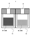
- FIG. 6 is a schematic cross-sectional view of a reagent bottle in which the first reagent accommodating portion and the second reagent accommodating portion have the same shape among the reagent bottles in the automatic analyzer according to the present embodiment.
- FIG. 6 is a schematic cross-sectional view of a reagent bottle having a different shape between the first reagent accommodating portion and the second reagent accommodating portion among the reagent bottles in the automatic analyzer according to the present embodiment.
- the control block diagram regarding the orientation determination of the reagent bottle in the automatic analyzer which concerns on this embodiment The conceptual diagram of the analysis parameter and the reagent bottle association in the automatic analyzer which concerns on this embodiment.
- the conceptual diagram of the reagent descent height in the automatic analyzer which concerns on this embodiment The flowchart of the reagent descent height in the automatic analyzer which concerns on this embodiment.
- FIGS. 1 to 15 Examples of the automatic analyzer of the present invention and the reagent registration method in the automatic analyzer will be described with reference to FIGS. 1 to 15.
- the same or corresponding components may be designated by the same or similar reference numerals, and repeated description of these components may be omitted.
- FIG. 1 is a schematic view showing an embodiment of an automatic analyzer to which the present invention is applied
- FIG. 2 is a schematic view of a reagent disk of the automatic analyzer
- FIG. 3 is an automatic analyzer according to the present embodiment.
- FIG. 4 and FIG. 5 are schematic views of the cross section of the reagent bottle.
- the automatic analyzer 200 for analyzing the sample shown in FIG. 1 includes a reaction disk 1, a sample transfer mechanism 8, a sample dispensing mechanism 9, a reagent disk 3, a reagent dispensing mechanism 11, 13, a cleaning mechanism 15, a light source 16a, and a spectroscopy. It is equipped with a photometric meter 16b, stirring mechanisms 17, 18, cleaning tanks 19, 20, 21, 22, 23, an operation unit 24, and the like.
- Reaction vessels 2 are arranged in a circle on the reaction disk 1, and a heat conductive medium (heat medium) whose temperature is controlled at 37 ° C., for example, a reaction tank 5 filled with water (hereinafter, also referred to as a constant temperature bath). Soaked in.
- the temperature of the reaction vessel 2 is always maintained at around 37 degrees by circulating the constant temperature water in the reaction vessel 5.
- a sample transport mechanism 8 for moving the rack 7 on which the sample container 6 is placed is installed near the reaction disk 1.
- a sample dispensing mechanism 9 that can rotate and move up and down is installed between the reaction disk 1 and the sample transport mechanism 8, and is provided with a sample nozzle 10.
- reagent bottle 4 in which a plurality of reagent containers 4A and 4B containing one type of reagent are collected can be installed on the inner and outer circumferences of a circle. be.
- the reagent disk 3 is provided with information medium reading mechanisms 27, 28, openings (not shown), and the like.
- the information medium reading mechanisms 27 and 28 can read the first reagent information recorded on the information medium 29 (see FIG. 3) such as RFID attached to the reagent bottle 4.
- the information medium 29 is an RFID and the information medium reading mechanisms 27 and 28 are RFID readers, but the medium and the reading method may be used as long as the system can read necessary information.
- the information medium 29, an IC or the like having a function of reading / writing a barcode or information can be used as the information medium 29, an IC or the like having a function of reading / writing a barcode or information can be used.
- the opening is arranged on the cover of the reagent disk 3 for dispensing the reagent.
- the suction of the reagent rotates the reagent disk 3 so that the reagent bottle 4 required for measurement is placed under the opening of the reagent disk 3.
- Reagent suction is performed at a position where the opening of the reagent disk 3 and the opening 26 of the reagent bottle 4 overlap.
- the reagent bottle 4 is composed of a composite of a plurality of reagent containers 4A and 4B, or a form in which the inside of the reagent bottle 4 is partitioned by a partition.
- the reagent bottle 4 has an information medium 29, for example, an RFID label attached to the upper surface thereof.
- the reagent bottle 4 can be filled with a plurality of types of reagents in one bottle.
- the first reagent and the second reagent are filled as reagents for reacting the sample will be described.
- the same shape may be combined as shown in FIG. 4, or different shapes may be combined as shown in FIG.
- the same shape may be combined as shown in FIG. 4, or different shapes may be combined as shown in FIG.
- Reagent bottle 4 installation orientation determination can be performed.
- the amount of reagent filled in the reagent bottle 4 is specified in advance, and the amount specified at the manufacturing stage is filled and sold.
- the reagent dispensing mechanisms 11 and 13 that can rotate and move up and down are installed between the reaction disk 1 and the reagent disk 3, and the reagent is dispensed from the reagent containers 4A and 4B of the reagent bottle 4.
- the reagent nozzles 12 and 14 are provided.
- the reagent dispensing mechanisms 11 and 13 include liquid level sensors 11a and 13a (see FIG. 6) for detecting the liquid level of the reagent in the reagent containers 4A and 4B of the reagent bottle 4, and a reagent nozzle during reagent suction.
- Pressure sensors 11b and 13b are provided for detecting whether or not the suction and discharge of the reagent are normally performed by detecting the pressure in 12 and 14.
- liquid level sensors 11a and 13a include a configuration in which a change in the capacitance of the reagent nozzles 12 and 14 is detected to determine the presence or absence of a liquid level, and the liquid level sensors 11a and 13a can detect the liquid height in the reagent bottle 4. If so, the form does not matter.
- a cleaning mechanism 15 Around the reaction disk 1, a cleaning mechanism 15, a light source 16a that irradiates the reagent with light, a spectrophotometer 16b that measures the optical characteristics of the light that has passed through the reagent, and stirring mechanisms 17, 18 are provided. Have been placed. Cleaning tanks 19, 20, 21, 22, and 23 are installed within the operating range of the sample dispensing mechanism 9, the reagent dispensing mechanism 11, 13, and the stirring mechanism 17, 18, respectively.
- Dedicated pumps (not shown) are connected to the sample dispensing mechanism 9, the reagent dispensing mechanisms 11, 13 and the cleaning mechanism 15, respectively.
- the operation unit 24 is a part that plays a role of controlling the information of the entire automatic analyzer 200, and has an overall control unit 24-1, a storage unit 24-2, a display unit 24-3, and an input unit 24-4. There is.
- the operation unit 24 may be realized by using a general-purpose computer, or may be realized as a function of a program executed on the computer.
- the overall control unit 24-1 in the operation unit 24 is a part connected to the analysis unit 100 by a wired or wireless network line and controls the operation of the entire automatic analyzer 200.
- the processing of the overall control unit 24-1 may be realized by storing it as a program code in a recording unit such as a memory and executing each program code by a processor such as a CPU (Central Processing Unit).
- the overall control unit 24-1 may be configured by hardware such as a dedicated circuit board.
- the display unit 24-3 is a part on which various screens such as an operation screen for ordering measurement items to be measured for a sample to be measured, a screen for confirming the measurement result, and the like are displayed, and is composed of a liquid crystal display or the like. To. It is not necessary to use a liquid crystal display, and it may be replaced with a printer or the like. It may be composed of a display and a printer or the like, or a touch panel type display that also serves as an input unit 24-4 described later. can.
- the input unit 24-4 is a part for inputting various parameters and settings, measurement results, measurement request information, analysis start / stop instructions, etc. based on the operation screen displayed on the display unit 24-3. It consists of a keyboard and mouse.
- the storage unit 24-2 is a part that stores time charts and operation parameters necessary for the operation of each device constituting the automatic analyzer, various information for identifying a biological sample, measurement results, etc., and is a part such as a flash memory. It is composed of a storage medium such as a magnetic disk such as a semiconductor memory or an HDD.
- the automatic analyzer 200 measures the biochemical item
- the present invention is not limited to the form of measuring the biochemical item, and measures other items such as an immune item and an electrolyte item. It can be in the form of
- the automatic analyzer 200 is composed of one analysis unit
- two or more analysis units can be provided.
- the type of the analysis unit is not particularly limited, and one or more various analysis units such as a biochemical analysis unit, an immunoanalysis unit, and a blood coagulation analysis unit can be provided.
- the automatic analyzer 200 can be equipped with a transport unit.
- a dispensing operation is performed by the sample nozzle 10 according to the measurement items requested by the operation unit 24.
- the sample nozzle 10 discharges the sucked sample into the reaction vessel 2 on the reaction disk 1, and further adds the reagent sucked from the reagent bottle 4 of the reagent disk 3 by the reagent nozzles 12 and 14 to the reaction vessel 2. , Stir. After that, the optical characteristics of the reaction solution adjusted by stirring are measured by the spectrophotometer 16b, and the measurement result is transmitted to the overall control unit 24-1 of the operation unit 24.
- the overall control unit 24-1 obtains the concentration of a specific component in the sample by arithmetic processing from the transmitted measurement result.
- the analysis result is notified to the user via the display unit 24-3 and recorded in the storage unit 24-2.
- FIG. 6 is a control block diagram for determining the orientation of the reagent bottle
- FIG. 7 is a conceptual diagram of analysis parameters and reagent bottle association
- FIG. 8 is a flowchart of reagent bottle registration
- FIG. 9 is a flowchart of reagent bottle installation orientation information acquisition
- FIG. Is a flow chart for determining the liquid level
- FIGS. 11 and 12 are conceptual diagrams of the reagent descending height
- FIG. 13 is a flowchart for determining the liquid property
- FIG. 14 is a flowchart for determining the absorbance
- FIG. 15 is a diagram showing details of the absorbance determination. Is.
- the registration of the reagent is actually measured by the information acquisition unit and the first reagent information read from the information medium 29 attached to the reagent bottle 4 by the information medium reading mechanisms 27 and 28. This is done using the second reagent information for specifying the installation orientation of the reagent bottle 4 when it is installed on the reagent disk 3.
- the analysis unit 100 As shown in FIG. 6, as a configuration related to reagent registration, in the analysis unit 100, the information medium reading mechanisms 27 and 28, the spectrophotometer 16b, the liquid level sensors 11a and 13a of the reagent dispensing mechanisms 11 and 13, and the pressure are used. Examples thereof include sensors 11b and 13b.
- the overall control unit 24-1 include a medium reading determination unit 241a, a bottle suitability determination unit 241b, and a bottle installation orientation determination unit 241c.
- the storage unit 24-2 include a bottle information storage unit 242a, a position information storage unit 242a1, and a bottle code storage unit 242b.
- the information acquisition unit can actually measure the second reagent information by at least two different methods, and can be measured by the reagent dispensing mechanisms 11 and 13.
- the second reagent information is stored in the calculation results 607 and 609 of the absorbance measured by the spectrophotometer 16b and the absorbance between the reagents filled in the same reagent bottle 4 and in the bottle code storage unit 242b. It can be at least one of the deviation rates 608 and 610 of the absolute comparison for evaluating the deviation between the measured absorbance information and the measured absorbance.
- the highest priority is given to the detection of the reagent liquid level, the pressure waveform data at the time of suction of the reagent, and the absorbance of the reagent.
- the method to be performed can be the detection of the reagent liquid level, and then the pressure waveform data.
- the medium reading determination unit 241a of the overall control unit 24-1 determines whether or not the information medium 29 of the reagent bottle 4 has been read by the information medium reading mechanisms 27 and 28, so that the reagent bottle 4 is installed at the reagent installation position. Determine if it is.
- the bottle suitability determination unit 241b collates the read information of the first reagent from the information medium 29 with the bottle code in the analysis parameter stored in the bottle code storage unit 242b in the storage unit 24-2, and collates with the analysis parameter. Determine if the bottle code matches.
- the first reagent information of the reagent bottle 4 is information including an item name, a bottle code, an expiration date, a lot, and the like.
- the bottle code is an identification number for associating the reagent bottle 4 with the analysis parameter using the reagent, and by comparing with the bottle code or lot of the first reagent information, the analysis related to the installed reagent is performed. Identify the parameters.
- the analysis parameters are downloaded into the bottle code storage unit 242b using an online database or an external storage medium as shown in FIG. 7. Information necessary for analysis such as analysis parameter number, item name, wavelength, sample dispensing amount, and reagent dispensing amount is stored in the analysis parameter.
- Analytical parameters include analytical parameter bottle information in addition to the information described above.
- the analysis parameter bottle information is the filling amount information of the reagent filled in the bottle code and the target bottle, and the viscosity and absorbance information used for the determination described later.
- the analysis parameter bottle information also stores the determination method used for acquiring the second reagent information. For example, in FIG. 7, the liquid level height determination and the liquid property determination can be performed, and the absorbance determination cannot be performed.
- the determination method used for acquiring the second reagent information in FIG. 7, it is possible to set to use all or any of the three methods. In this case, it is possible to select an available determination method. In addition, when two or more are selected, the priority of use can be set. Further, the discrimination may be performed by using a single mechanism in the automatic analyzer 200 or by using a plurality of mechanisms, and is not particularly limited.
- Information on analysis parameters such as reagent filling amount, liquid property information, and absorbance information is not limited to the form acquired online, and is originally recorded in the information medium 29 of the reagent bottle 4 as the first reagent information. It can be a form that is collectively acquired as the first reagent information or a form that is recorded in the storage unit 24-2.
- the bottle installation orientation determination unit 241c determines the installation orientation of the reagent bottle 4 from the first reagent information read by the information medium reading mechanisms 27 and 28 and the second reagent information actually measured by the information acquisition unit.
- the bottle installation orientation determination unit 241c includes a liquid level height determination unit 241c1, a liquid property determination unit 241c2, and an absorbance determination unit 241c3. The details will be described later.
- the bottle information storage unit 242a stores the first reagent information of the reagent bottle 4 read by the information medium reading mechanisms 27 and 28.
- the bottle information storage unit 242a has a position information storage unit 242a1 that stores information on the installation orientation of the reagent bottle 4.
- the bottle code storage unit 242b stores analysis parameters acquired from an online database or an external storage medium as shown in FIG. 7.
- the bottle code storage unit 242b may have an external configuration of the storage unit 24-2, that is, the automatic analyzer 200, or may be an online database or an external storage medium.
- step S101 the user opens the lid of the reagent disk 3 (step S101) and installs the reagent bottle 4 (step S102).
- steps S101 and S102 correspond to the installation process.
- the apparatus may be equipped with a mechanism (autoloader) for automatically installing the reagent bottle 4 on the reagent disk 3.
- a mechanism autoloader
- the reagent bottle 4 is installed on the reagent disk 3 as shown in FIG. 2, it can be installed without considering the installation orientation of the reagent bottle 4.
- step S103 After that, after installing the necessary reagent bottle 4 on the reagent disc 3, the lid of the reagent disc 3 is closed (step S103).
- the start timing may be automatically started at the timing when the lid of the reagent disk 3 is closed, or the user may issue an instruction to start reading the reagent bottle 4 information from the screen.
- the installation positions of all the reagent bottles 4 pass through the positions of the information medium reading mechanisms 27 and 28 in order to read the information medium 29 attached to the reagent bottle 4.
- the reagent disk 3 rotates (step S104). This step S104 corresponds to the information medium reading step.
- the bottle suitability determination unit 241b collates with the bottle code in the analysis parameter stored in the bottle code storage unit 242b, and determines whether or not the analysis parameter and the bottle code match (step S108).
- step S110 corresponds to the information acquisition step and the discrimination step.
- step S110 Information on the installation orientation of the reagent bottle 4 for the target reagent bottle 4 is acquired by three determinations of "liquid level determination”, “liquid property determination”, and "absorbance determination”. The detailed method of each determination will be described later with reference to FIGS. 10 and later.
- the target bottle code in the analysis parameter it is set in advance which judgment is used to acquire the reagent bottle 4 installation orientation information. For example, when the liquid level heights of the first reagent and the second reagent in the reagent bottle 4 are different, it can be discriminated from the difference in the liquid level.
- Liquid property determination is a method of discriminating between the first reagent and the second reagent from the reagent liquid properties by using the pressure waveform data of the reagents when the viscosities of the first reagent and the second reagent are different as described later. be.
- the liquid level height is determined with respect to the target bottle code in the analysis parameter. Is enabled or not (step S201).
- step S202A the liquid level height determination is executed (step S202A), and it is determined whether or not the determination can be performed without any problem (step). S202B).
- step S208 the liquid level height cannot be detected (determination NG)
- step S207 the process proceeds to step S207.
- step S201 determines whether or not the liquid level determination is valid. If it is determined in step S201 that the liquid level determination is not valid, the process proceeds to step S203, and is the liquid property determination valid for the target bottle code in the analysis parameter? It is determined whether or not (step S203).
- step S204A the liquid property determination is executed (step S204A), and it is determined whether or not the determination can be performed without any problem (step S204B). If the liquid property can be determined, the process proceeds to step S208, and if the liquid property cannot be determined (determination NG), the process proceeds to step S207.
- step S203 when it is determined in step S203 that the liquid property determination is not valid, the process proceeds to step S205, and whether or not the absorbance determination is valid for the target bottle code in the analysis parameter is determined. Determination (step S205).
- step S206A the absorbance determination is executed (step S206A), and it is determined whether or not the determination can be performed without any problem (step S206B).
- step S208 the absorbance determination is executed (step S208)
- step S207 the process proceeds to step S207.
- step S208 it is determined how the suction position of the reagent, that is, the installation direction of the reagent bottle 4 is arranged (step S208), the reagent. End the acquisition of information for bottle installation.
- step S205 when the discrimination method is not set (No in step S205) or when various judgments are NG (determination NG in steps S202B, S204B, S206B), the target reagent bottle 4 cannot be registered (step). S207), the acquisition of information on the reagent bottle installation orientation is completed.
- the procedure of the procedure is not limited to the above-mentioned flow. For example, when it is determined in step S202B that the liquid level height detection is NG, the process is advanced to step S203 and whether or not the liquid property determination can be executed. The procedure can be used to determine the installation orientation of the reagent bottle 4 as much as possible.
- step S202A of FIG. 9 the details of the liquid level height determination in step S202A of FIG. 9 will be described with reference to FIGS. 10 to 12.
- the liquid level height is determined by using the liquid level sensors 11a and 13a provided in the reagent dispensing mechanisms 11 and 13.
- the liquid level height determination unit 241c1 first acquires the set height information of the first reagent and the second reagent set in the analysis parameters ( Step S301).
- the liquid level height determination unit 241c1 determines the amount of descent of the reagent nozzles 12 and 14 to the reagent bottle 4 based on the acquired set height information.
- the amount of descent of the reagent nozzles 12 and 14 varies depending on the relationship between the liquid heights of the first reagent and the second reagent.
- the liquid height of the set first reagent is higher than that of the second reagent
- the liquid height of the set first reagent is aimed at (case 1 in FIG. 10), and the set second reagent is used.
- the liquid height of the second reagent is set (case 2 in FIG. 10), and the liquid level height determination unit 241c1 lowers either the reagent nozzles 12 or 14. (Step S302).
- the reagent nozzle 12 is lowered.
- the side closer to the center direction of the reagent disk 3 is the position A
- the side farther from the center direction is the position B
- the reagent nozzle 12 is lowered with respect to the position A.
- the position A The reagent nozzle 12 is lowered to a height at which the reagent nozzle 12 is immersed in the liquid surface of either the or position B.
- a method of detecting the liquid level there are (1) a method of lowering while searching for the liquid level, and (2) a method of aiming at the position of the liquid level acquired in advance from the analysis parameters by software and lowering to that point.
- a method of lowering while searching for the liquid level there are (1) a method of lowering while searching for the liquid level, and (2) a method of aiming at the position of the liquid level acquired in advance from the analysis parameters by software and lowering to that point.
- Step S303 the presence or absence of the liquid level is confirmed by the liquid level sensors 11a and 13a (step S303), and it is determined whether or not the liquid level is detected.
- Step S304 the position of position A is determined to be the first reagent and position B is determined to be the second reagent, and in case 2, the position of position A is determined to be the second reagent and position B is the second reagent. Determined to be the first reagent (step S305).
- Step S306 it is determined whether or not the liquid level is detected (step S307).
- the reason for accessing the higher one first in step S302 is that, as shown in FIG. 11, when the liquid height of the first reagent set is higher than that of the second reagent, the higher first reagent is used.
- the reagent nozzle 12 is lowered toward the liquid height, only one of the reagents needs to enter the liquid surface, but as shown in FIG. 12, the reagent nozzle 12 is aimed at the liquid height of the second reagent on the lower side. This is because when is lowered, both reagents enter the liquid and the liquid level is detected in both of them. Further, the amount of the reagent nozzle 12 plunged into the reagent becomes large, and it is necessary to perform a lot of cleaning, which is to avoid this.
- This step S306 is a process for confirming that it is the second reagent, and it is also possible to omit it and register only the determination results of steps S303 and S304.
- the reagent bottle 4 is composed of three or more reagent containers, it is desirable to perform the treatments of this step S306 and the subsequent steps S307 at least once.
- step S306 the position of position A is determined to be the second reagent in case 1, position B is determined to be the first reagent, and in case 2, the position of position A is determined to be the first reagent.
- Position B is determined to be the second reagent (step S308).
- the reagent position information determined in step S305 or step S308 is registered in the position information storage unit 242a1 as installation orientation information (reagent suction position information) of the reagent bottle 4 (step S310), and the process ends.
- the pressure sensors 11b and 13b provided in the reagent dispensing mechanism 11 are used for the liquid property determination.
- the liquid property determination unit 241c2 first acquires the liquid level height and the liquid property information of the first reagent and the second reagent set in the analysis parameters ( Step S401).
- viscosity information is used as liquid information.
- the viscosity information indicates the pressure waveform data when the apparatus sucks the first reagent and the second reagent in the reagent bottle 4.
- the liquid property determination unit 241c2 lowers one of the reagent nozzles 12 to one position of the reagent bottle 4 (step S402).
- the vehicle is lowered to position A.
- the amount of descent of the reagent nozzle 12 at this time is to the lower of the set height of the first reagent and the set liquid height of the second reagent in order to surely enter the liquid surface. It shall be lowered.
- step S403 the liquid level is confirmed (step S403), and it is determined whether or not the liquid level can be confirmed (step S404). If it can be confirmed, the reagent is sucked (step S405) and the pressure data is acquired (step S406).
- the amount of reagent suction at this time shall be a specified amount to the extent that pressure data can be obtained. Here, it is defined as 50 ⁇ L.
- Step S4114 If the liquid level is not detected in steps S403 and S408 and No is determined in steps S404 and S409, it is highly likely that an inappropriate reagent is contained, and the reagent bottle 4 cannot be registered. (Step S414).
- step S412 After acquiring the pressure data of position A and position B, comparative analysis is performed with the pressure waveform data stored in the bottle code storage unit 242b in advance, and position A and position B are assigned to either the first reagent or the second reagent, respectively. It is determined whether it is classified (step S412).
- the method is not limited as long as the similarity between the referenced pressure waveform data and the actually measured pressure waveform data can be quantitatively discriminated.
- step S413 If the determination is possible, the suction position information is registered (step S413). If it cannot be determined, it cannot be registered (step S414).
- the pressure waveform information to be referred to may be updated using the online database or external media for each reagent lot.
- step S206A of FIG. 9 the details of the absorbance determination in step S206A of FIG. 9 will be described with reference to FIGS. 14 and 15.
- Absorbance determination is performed using the reagent dispensing mechanisms 11 and 13, the reaction vessel 2 of the reaction disk 1, the light source 16a, and the spectrophotometer 16b.
- the absorbance determination unit 241c3 first acquires the liquid level height and the absorbance information set in the analysis parameters (step S501).
- the absorbance determination unit 241c3 lowers the reagent nozzle 12 to the lower of the set liquid height of the first reagent and the set liquid height of the second reagent with respect to the position A. (Step S502). After the reagent nozzle 12 is lowered, the presence or absence of the liquid level is confirmed (step S503), and it is determined whether or not the liquid level can be confirmed (step S504).
- the absorbance determination unit 241c3 sucks the reagent (step S505).
- the reagent suction amount at this time is "minimum amount of liquid that can be measured by the reaction vessel + extra amount".
- the excess amount refers to the amount of reagent to be sucked in excess to avoid diluting the reagent due to pure water filling the reagent nozzle.
- the minimum liquid amount is determined by the shape of the reaction vessel, and is 75 ⁇ L here.
- step S507 the reagent nozzle 12 is lowered to the same liquid level as in step S502 (step S507), the liquid level is confirmed (step S508), and it is determined whether or not the liquid level can be confirmed (step S509).
- the absorbance determination unit 241c3 sucks the reagent (step S510) and discharges the reagent to the reaction vessel 2 different from the reagent at position A (step S511).
- the reagent suction / discharge amount at this time is the same as that at the position A.
- the absorbance measurement is an operation of rotating the reaction disk 1 and measuring the amount of light emitted from the light source 16a and transmitted through the discharged reagent with a spectrophotometer 16b to obtain the absorbance of each reagent.
- the absorbance is measured after all the reagents have been discharged from the target reagent bottle 4 to the reaction vessel 2. Transition to.
- the wavelength to be acquired at the time of absorbance measurement may be a designated wavelength or any wavelength that can be acquired by the apparatus.
- Absorbance determination is performed by comparing the absorbance information set in the analysis parameters in advance with the measured absorbance.
- FIG. 15 shows an example of absorbance determination.
- FIG. 15 shows the measured absorbance 601 of the reagent bottle 4 in the reagent containers 4A and 4B, and the in-device absorbance information 602 of the bottle code “10001” stored in the bottle code storage unit 242b.
- the measured absorbance 601 indicates the measured absorbance of all 12 wavelengths that can be measured by the spectrophotometer 16b.
- the in-device absorbance information 602 is a theoretical value of the absorbance at a specific wavelength or a value actually measured before the reagent is shipped, and is shown here as a theoretical value at two wavelengths. For the absorbance determination, the difference between the theoretical value of the absorbance information 602 in the apparatus and the measured absorbance 601 is used.
- the absorbance of the reagent may vary depending on the reagent lot. Therefore, it is possible to update the absorbance information in the apparatus by using an online database or an external medium for each reagent lot. In addition, since some reagents have a gradual change in absorbance after the reagent is manufactured, it can be determined from the ratio or difference in absorbance between the first reagent and the second reagent at a certain wavelength.
- the difference between the absorbance of the first reagent set in the analysis parameter bottle information and the measured absorbance of the corresponding wavelengths of a and b is calculated 603,604.
- the relative determination of a and b is performed. In the relative determination, the smaller value is selected from the calculation results 607 and 609 of the absorbance difference. In the example of FIG. 15, the calculation result 607 is selected.
- the difference between the absorbance of the second reagent set in the analysis parameter bottle information and the measured absorbance of the corresponding wavelengths of a and b is calculated 605 and 606.
- the relative determination of a and b is performed. In the relative determination, the smaller value is selected from the calculation results 607 and 609 of the absorbance difference. In the example of FIG. 15, the calculation result 609 is selected.
- the absolute judgment it is confirmed whether the measured absorbance of b is within ⁇ 20% of the absorbance information in the apparatus on the selected side, and in FIG.
- b is determined to be the second reagent in the example of FIG.
- the value of the deviation rate an arbitrary value can be set for each reagent in consideration of the measurement performance of the device, the formulation of the reagent, the variation in the manufacturing process, and the like. Further, it may be judged by using the difference from the absorbance in the apparatus instead of the ratio.
- the absorbance determination unit 241c3 determines the position information of the first reagent and the second reagent as the final determination 611.
- a is the first reagent and b is the second reagent.
- the absorbance determination unit 241c3 determines whether or not the first reagent and the second reagent can be discriminated (step S513), and when it is determined that the discrimination is possible, the reagent suction position information is stored in the position information. Register in the unit 242a1 (step S514). If it is determined that the first reagent and the second reagent cannot be distinguished due to an abnormality in the measured absorbance, the corresponding reagent bottle 4 cannot be registered (step S515).
- the automatic analyzer 200 for analyzing the sample of the present embodiment described above is attached to the reagent disk 3 and the reagent bottle 4 in which a plurality of reagent bottles 4 in which a plurality of reagent containers 4A and 4B containing one type of reagent are collected can be installed.
- the installation orientation of the reagent bottle 4 is determined from the first reagent information read by the information medium reading mechanisms 27 and 28 and the second reagent information actually measured by the information acquisition unit. do.
- the automatic analyzer is required to have stable operation with few troubles and to reduce user work, especially complicated work.
- the burden on the user can be reduced.
- the information acquisition unit can actually measure the second reagent information by at least two different methods, it becomes possible to handle the reagent bottles 4 in various shapes and states, further reducing the burden on the user.
- a storage unit 24-2 for storing information on which method is used among the two or more actual measurement methods of the second reagent information the characteristics of the corresponding reagent and the reagent bottle 4 can be met. Since the installation orientation of the reagent bottle 4 can be determined, more accurate and stable determination is possible.
- the reagent dispensing mechanisms 11 and 13 provided with the reagent nozzles 12 and 14 for dispensing the reagent from the reagent containers 4A and 4B of the reagent bottle 4 are further provided, and the second reagent information is transmitted by the reagent dispensing mechanisms 11 and 13.
- the reagent liquid level height actually measured by the liquid level sensors 11a and 13a provided in the reagent dispensing mechanisms 11 and 13 can be set, and the reagent dispensing mechanisms 11 and 13 are provided at the time of suction of the reagent.
- the pressure waveform data actually measured by the pressure sensors 11b and 13b it is possible to determine the installation orientation according to the configuration originally provided in the device required for reagent dispensing, so it is suitable for inexpensive and reliable installation. Judgment can be realized.
- a light source 16a for irradiating the reagent with light and a spectrophotometer 16b for measuring the optical characteristics of the light irradiated from the light source 16a and passing through the reagent are further provided, and the second reagent information is transmitted by the spectrophotometer 16b.
- the installation orientation can be determined only with the configuration originally provided in the analyzer.
- the second reagent information is absolutely compared between the absorbances of the reagents filled in the same reagent bottle 4 and the deviation between the absorbance information stored in the bottle code storage unit 242b and the measured absorbance is evaluated. By using at least one of the comparisons, more accurate installation orientation determination can be performed.
- the actual measurement method of the second reagent information is the detection of the reagent liquid level, the pressure waveform data at the time of suction of the reagent, and the absorbance of the reagent, the most preferred method is the detection of the reagent liquid level. Then, by using the pressure waveform data, the installation orientation determination can be executed in the order in which the post-processing after the determination is executed is easy.
- Display unit 24-4 ... Input unit 26 ... Opening 27 ... Information medium reading mechanism (inside reagent disk) 28 ... Information medium reading mechanism (outside of reagent disk) 29 ... Information medium 100 ... Analysis unit 200 ... Automatic analyzer 241a ... Medium reading determination unit 241b ... Bottle suitability determination unit 241c ... Judgment unit 241c1 ... Judgment unit 241c2 ... Liquid property determination unit 241c3 ... Absorbance determination unit 242a ... Bottle information storage unit 242a1 ... Position information storage unit 242b ... Bottle code storage unit 601 ... Measured absorbance 602 ... In-device absorbance information 603,604,605,606 ... Difference 607,609 ... Calculation result 608,610 ... Deviation rate 611 ... Final determination
Landscapes
- Physics & Mathematics (AREA)
- Health & Medical Sciences (AREA)
- Life Sciences & Earth Sciences (AREA)
- Chemical & Material Sciences (AREA)
- Analytical Chemistry (AREA)
- Biochemistry (AREA)
- General Health & Medical Sciences (AREA)
- General Physics & Mathematics (AREA)
- Immunology (AREA)
- Pathology (AREA)
- Automatic Analysis And Handling Materials Therefor (AREA)
Priority Applications (1)
| Application Number | Priority Date | Filing Date | Title |
|---|---|---|---|
| JP2022536124A JP7522835B2 (ja) | 2020-07-15 | 2021-02-25 | 自動分析装置、および自動分析装置における試薬登録方法 |
Applications Claiming Priority (2)
| Application Number | Priority Date | Filing Date | Title |
|---|---|---|---|
| JP2020-121462 | 2020-07-15 | ||
| JP2020121462 | 2020-07-15 |
Publications (1)
| Publication Number | Publication Date |
|---|---|
| WO2022014082A1 true WO2022014082A1 (ja) | 2022-01-20 |
Family
ID=79554616
Family Applications (1)
| Application Number | Title | Priority Date | Filing Date |
|---|---|---|---|
| PCT/JP2021/007128 Ceased WO2022014082A1 (ja) | 2020-07-15 | 2021-02-25 | 自動分析装置、および自動分析装置における試薬登録方法 |
Country Status (2)
| Country | Link |
|---|---|
| JP (1) | JP7522835B2 (enExample) |
| WO (1) | WO2022014082A1 (enExample) |
Citations (7)
| Publication number | Priority date | Publication date | Assignee | Title |
|---|---|---|---|---|
| JP2008309777A (ja) * | 2007-05-15 | 2008-12-25 | Hitachi High-Technologies Corp | 液体分注装置 |
| JP2010534827A (ja) * | 2007-07-27 | 2010-11-11 | エフ.ホフマン−ラ ロシュ アーゲー | 方向識別ラベル、試薬容器搬送構造、分析装置および読取モジュール |
| JP2011027658A (ja) * | 2009-07-29 | 2011-02-10 | Hitachi High-Technologies Corp | 自動分析装置 |
| JP2013134145A (ja) * | 2011-12-26 | 2013-07-08 | Hitachi High-Technologies Corp | 自動分析装置 |
| JP2018506712A (ja) * | 2015-01-23 | 2018-03-08 | エフ.ホフマン−ラ ロシュ アーゲーF. Hoffmann−La Roche Aktiengesellschaft | 分析機器の試薬ロータに試薬容器を装填するための装填デバイス、および、分析機器 |
| WO2018173464A1 (ja) * | 2017-03-24 | 2018-09-27 | 株式会社日立ハイテクノロジーズ | 自動分析装置 |
| WO2020059231A1 (ja) * | 2018-09-21 | 2020-03-26 | 株式会社日立ハイテクノロジーズ | 自動分析装置 |
-
2021
- 2021-02-25 JP JP2022536124A patent/JP7522835B2/ja active Active
- 2021-02-25 WO PCT/JP2021/007128 patent/WO2022014082A1/ja not_active Ceased
Patent Citations (7)
| Publication number | Priority date | Publication date | Assignee | Title |
|---|---|---|---|---|
| JP2008309777A (ja) * | 2007-05-15 | 2008-12-25 | Hitachi High-Technologies Corp | 液体分注装置 |
| JP2010534827A (ja) * | 2007-07-27 | 2010-11-11 | エフ.ホフマン−ラ ロシュ アーゲー | 方向識別ラベル、試薬容器搬送構造、分析装置および読取モジュール |
| JP2011027658A (ja) * | 2009-07-29 | 2011-02-10 | Hitachi High-Technologies Corp | 自動分析装置 |
| JP2013134145A (ja) * | 2011-12-26 | 2013-07-08 | Hitachi High-Technologies Corp | 自動分析装置 |
| JP2018506712A (ja) * | 2015-01-23 | 2018-03-08 | エフ.ホフマン−ラ ロシュ アーゲーF. Hoffmann−La Roche Aktiengesellschaft | 分析機器の試薬ロータに試薬容器を装填するための装填デバイス、および、分析機器 |
| WO2018173464A1 (ja) * | 2017-03-24 | 2018-09-27 | 株式会社日立ハイテクノロジーズ | 自動分析装置 |
| WO2020059231A1 (ja) * | 2018-09-21 | 2020-03-26 | 株式会社日立ハイテクノロジーズ | 自動分析装置 |
Also Published As
| Publication number | Publication date |
|---|---|
| JP7522835B2 (ja) | 2024-07-25 |
| JPWO2022014082A1 (enExample) | 2022-01-20 |
Similar Documents
| Publication | Publication Date | Title |
|---|---|---|
| EP1873530B1 (en) | Sample analyzer | |
| US8758684B2 (en) | Automatic analyzer | |
| JP5669528B2 (ja) | 自動分析装置 | |
| EP1873531A2 (en) | Sample analyzer and sample analyzing method | |
| CN102037363A (zh) | 自动分析装置 | |
| JP2000310643A (ja) | 自動分析装置 | |
| JP5535047B2 (ja) | 自動分析装置 | |
| CN101661045A (zh) | 组合试剂容器及使用该组合试剂容器的自动分析装置 | |
| WO2020179246A1 (ja) | 自動分析装置 | |
| JP6824006B2 (ja) | 自動分析装置及びプログラム | |
| JP5591674B2 (ja) | 自動分析装置および試薬容器保管装置 | |
| JP2007303937A (ja) | 自動分析装置 | |
| JP7494374B2 (ja) | 自動分析装置および自動分析装置の制御方法 | |
| JP6429753B2 (ja) | 自動分析装置及び自動分析方法 | |
| JP6419641B2 (ja) | 自動分析装置及び多重測定方法 | |
| JP7522835B2 (ja) | 自動分析装置、および自動分析装置における試薬登録方法 | |
| CN112955749B (zh) | 异常判定方法和自动分析装置 | |
| CN114450595B (zh) | 试剂管理方法 | |
| WO2010079630A1 (ja) | 分析装置 | |
| JP7433459B2 (ja) | 自動分析装置 | |
| JP2015049063A (ja) | 検体分析装置 | |
| JP2007303884A (ja) | 自動分析装置 | |
| JP2023127333A (ja) | 自動分析装置、プログラム、および記憶媒体、並びに方法 | |
| CN116830205A (zh) | 自动分析系统以及自动分析系统中的信息继承方法 | |
| EP3553530B1 (en) | Automatic analyzer and program |
Legal Events
| Date | Code | Title | Description |
|---|---|---|---|
| 121 | Ep: the epo has been informed by wipo that ep was designated in this application |
Ref document number: 21840421 Country of ref document: EP Kind code of ref document: A1 |
|
| ENP | Entry into the national phase |
Ref document number: 2022536124 Country of ref document: JP Kind code of ref document: A |
|
| NENP | Non-entry into the national phase |
Ref country code: DE |
|
| 122 | Ep: pct application non-entry in european phase |
Ref document number: 21840421 Country of ref document: EP Kind code of ref document: A1 |