EP1873531A2 - Sample analyzer and sample analyzing method - Google Patents
Sample analyzer and sample analyzing method Download PDFInfo
- Publication number
- EP1873531A2 EP1873531A2 EP07012707A EP07012707A EP1873531A2 EP 1873531 A2 EP1873531 A2 EP 1873531A2 EP 07012707 A EP07012707 A EP 07012707A EP 07012707 A EP07012707 A EP 07012707A EP 1873531 A2 EP1873531 A2 EP 1873531A2
- Authority
- EP
- European Patent Office
- Prior art keywords
- reagent
- sample
- container
- reagent container
- replacement
- Prior art date
- Legal status (The legal status is an assumption and is not a legal conclusion. Google has not performed a legal analysis and makes no representation as to the accuracy of the status listed.)
- Granted
Links
- 238000000034 method Methods 0.000 title claims description 70
- 239000003153 chemical reaction reagent Substances 0.000 claims abstract description 853
- 238000005259 measurement Methods 0.000 claims abstract description 93
- 238000004458 analytical method Methods 0.000 claims abstract description 31
- 230000003287 optical effect Effects 0.000 description 103
- 230000008569 process Effects 0.000 description 52
- BPYKTIZUTYGOLE-IFADSCNNSA-N Bilirubin Chemical compound N1C(=O)C(C)=C(C=C)\C1=C\C1=C(C)C(CCC(O)=O)=C(CC2=C(C(C)=C(\C=C/3C(=C(C=C)C(=O)N\3)C)N2)CCC(O)=O)N1 BPYKTIZUTYGOLE-IFADSCNNSA-N 0.000 description 16
- 238000004590 computer program Methods 0.000 description 14
- 210000001268 chyle Anatomy 0.000 description 13
- 239000000126 substance Substances 0.000 description 12
- 238000012360 testing method Methods 0.000 description 12
- 238000004891 communication Methods 0.000 description 11
- 230000031700 light absorption Effects 0.000 description 10
- 102000001554 Hemoglobins Human genes 0.000 description 9
- 108010054147 Hemoglobins Proteins 0.000 description 9
- 230000015271 coagulation Effects 0.000 description 8
- 238000005345 coagulation Methods 0.000 description 8
- 239000013307 optical fiber Substances 0.000 description 7
- 239000012530 fluid Substances 0.000 description 4
- 238000002835 absorbance Methods 0.000 description 3
- 238000010586 diagram Methods 0.000 description 3
- 238000010438 heat treatment Methods 0.000 description 3
- 230000007246 mechanism Effects 0.000 description 3
- 238000012545 processing Methods 0.000 description 3
- 239000000758 substrate Substances 0.000 description 3
- PGOHTUIFYSHAQG-LJSDBVFPSA-N (2S)-6-amino-2-[[(2S)-5-amino-2-[[(2S)-2-[[(2S)-2-[[(2S)-2-[[(2S)-4-amino-2-[[(2S)-2-[[(2S)-2-[[(2S)-2-[[(2S)-2-[[(2S)-5-amino-2-[[(2S)-5-amino-2-[[(2S)-2-[[(2S)-2-[[(2S)-2-[[(2S,3R)-2-[[(2S)-5-amino-2-[[(2S)-2-[[(2S)-2-[[(2S,3R)-2-[[(2S)-2-[[(2S)-2-[[(2S)-2-[[(2S)-2-[[(2S)-5-amino-2-[[(2S)-1-[(2S,3R)-2-[[(2S)-2-[[(2S)-2-[[(2R)-2-[[(2S)-2-[[(2S)-2-[[2-[[(2S)-2-[[(2S)-2-[[(2S)-2-[[(2S)-1-[(2S)-2-[[(2S)-2-[[(2S)-2-[[(2S)-2-amino-4-methylsulfanylbutanoyl]amino]-3-(1H-indol-3-yl)propanoyl]amino]-5-carbamimidamidopentanoyl]amino]propanoyl]pyrrolidine-2-carbonyl]amino]-3-methylbutanoyl]amino]-4-methylpentanoyl]amino]-4-methylpentanoyl]amino]acetyl]amino]-3-hydroxypropanoyl]amino]-4-methylpentanoyl]amino]-3-sulfanylpropanoyl]amino]-4-methylsulfanylbutanoyl]amino]-5-carbamimidamidopentanoyl]amino]-3-hydroxybutanoyl]pyrrolidine-2-carbonyl]amino]-5-oxopentanoyl]amino]-3-hydroxypropanoyl]amino]-3-hydroxypropanoyl]amino]-3-(1H-imidazol-5-yl)propanoyl]amino]-4-methylpentanoyl]amino]-3-hydroxybutanoyl]amino]-3-(1H-indol-3-yl)propanoyl]amino]-5-carbamimidamidopentanoyl]amino]-5-oxopentanoyl]amino]-3-hydroxybutanoyl]amino]-3-hydroxypropanoyl]amino]-3-carboxypropanoyl]amino]-3-hydroxypropanoyl]amino]-5-oxopentanoyl]amino]-5-oxopentanoyl]amino]-3-phenylpropanoyl]amino]-5-carbamimidamidopentanoyl]amino]-3-methylbutanoyl]amino]-4-methylpentanoyl]amino]-4-oxobutanoyl]amino]-5-carbamimidamidopentanoyl]amino]-3-(1H-indol-3-yl)propanoyl]amino]-4-carboxybutanoyl]amino]-5-oxopentanoyl]amino]hexanoic acid Chemical compound CSCC[C@H](N)C(=O)N[C@@H](Cc1c[nH]c2ccccc12)C(=O)N[C@@H](CCCNC(N)=N)C(=O)N[C@@H](C)C(=O)N1CCC[C@H]1C(=O)N[C@@H](C(C)C)C(=O)N[C@@H](CC(C)C)C(=O)N[C@@H](CC(C)C)C(=O)NCC(=O)N[C@@H](CO)C(=O)N[C@@H](CC(C)C)C(=O)N[C@@H](CS)C(=O)N[C@@H](CCSC)C(=O)N[C@@H](CCCNC(N)=N)C(=O)N[C@@H]([C@@H](C)O)C(=O)N1CCC[C@H]1C(=O)N[C@@H](CCC(N)=O)C(=O)N[C@@H](CO)C(=O)N[C@@H](CO)C(=O)N[C@@H](Cc1cnc[nH]1)C(=O)N[C@@H](CC(C)C)C(=O)N[C@@H]([C@@H](C)O)C(=O)N[C@@H](Cc1c[nH]c2ccccc12)C(=O)N[C@@H](CCCNC(N)=N)C(=O)N[C@@H](CCC(N)=O)C(=O)N[C@@H]([C@@H](C)O)C(=O)N[C@@H](CO)C(=O)N[C@@H](CC(O)=O)C(=O)N[C@@H](CO)C(=O)N[C@@H](CCC(N)=O)C(=O)N[C@@H](CCC(N)=O)C(=O)N[C@@H](Cc1ccccc1)C(=O)N[C@@H](CCCNC(N)=N)C(=O)N[C@@H](C(C)C)C(=O)N[C@@H](CC(C)C)C(=O)N[C@@H](CC(N)=O)C(=O)N[C@@H](CCCNC(N)=N)C(=O)N[C@@H](Cc1c[nH]c2ccccc12)C(=O)N[C@@H](CCC(O)=O)C(=O)N[C@@H](CCC(N)=O)C(=O)N[C@@H](CCCCN)C(O)=O PGOHTUIFYSHAQG-LJSDBVFPSA-N 0.000 description 2
- 108090000935 Antithrombin III Proteins 0.000 description 2
- 102100022977 Antithrombin-III Human genes 0.000 description 2
- 239000003154 D dimer Substances 0.000 description 2
- 108010049003 Fibrinogen Proteins 0.000 description 2
- 102000008946 Fibrinogen Human genes 0.000 description 2
- 108010094028 Prothrombin Proteins 0.000 description 2
- 102100027378 Prothrombin Human genes 0.000 description 2
- 108010000499 Thromboplastin Proteins 0.000 description 2
- 102000002262 Thromboplastin Human genes 0.000 description 2
- 238000001514 detection method Methods 0.000 description 2
- 230000006866 deterioration Effects 0.000 description 2
- 229940012952 fibrinogen Drugs 0.000 description 2
- 229940039716 prothrombin Drugs 0.000 description 2
- 239000002699 waste material Substances 0.000 description 2
- 102220469334 Pre-mRNA cleavage complex 2 protein Pcf11_S57A_mutation Human genes 0.000 description 1
- 238000013019 agitation Methods 0.000 description 1
- 230000005540 biological transmission Effects 0.000 description 1
- 210000004369 blood Anatomy 0.000 description 1
- 239000008280 blood Substances 0.000 description 1
- 230000008859 change Effects 0.000 description 1
- 238000006243 chemical reaction Methods 0.000 description 1
- 238000007405 data analysis Methods 0.000 description 1
- 238000007599 discharging Methods 0.000 description 1
- 230000000694 effects Effects 0.000 description 1
- 239000003925 fat Substances 0.000 description 1
- 108010052295 fibrin fragment D Proteins 0.000 description 1
- 230000020764 fibrinolysis Effects 0.000 description 1
- 238000011534 incubation Methods 0.000 description 1
- 238000003780 insertion Methods 0.000 description 1
- 230000037431 insertion Effects 0.000 description 1
- 238000009434 installation Methods 0.000 description 1
- 239000011810 insulating material Substances 0.000 description 1
- 238000012986 modification Methods 0.000 description 1
- 230000004048 modification Effects 0.000 description 1
- 230000010355 oscillation Effects 0.000 description 1
- 210000002381 plasma Anatomy 0.000 description 1
- 239000013589 supplement Substances 0.000 description 1
- 238000002834 transmittance Methods 0.000 description 1
- 238000005406 washing Methods 0.000 description 1
Images


Classifications
-
- G—PHYSICS
- G01—MEASURING; TESTING
- G01N—INVESTIGATING OR ANALYSING MATERIALS BY DETERMINING THEIR CHEMICAL OR PHYSICAL PROPERTIES
- G01N35/00—Automatic analysis not limited to methods or materials provided for in any single one of groups G01N1/00 - G01N33/00; Handling materials therefor
- G01N35/00584—Control arrangements for automatic analysers
-
- G—PHYSICS
- G01—MEASURING; TESTING
- G01N—INVESTIGATING OR ANALYSING MATERIALS BY DETERMINING THEIR CHEMICAL OR PHYSICAL PROPERTIES
- G01N35/00—Automatic analysis not limited to methods or materials provided for in any single one of groups G01N1/00 - G01N33/00; Handling materials therefor
- G01N35/02—Automatic analysis not limited to methods or materials provided for in any single one of groups G01N1/00 - G01N33/00; Handling materials therefor using a plurality of sample containers moved by a conveyor system past one or more treatment or analysis stations
- G01N35/025—Automatic analysis not limited to methods or materials provided for in any single one of groups G01N1/00 - G01N33/00; Handling materials therefor using a plurality of sample containers moved by a conveyor system past one or more treatment or analysis stations having a carousel or turntable for reaction cells or cuvettes
-
- B—PERFORMING OPERATIONS; TRANSPORTING
- B01—PHYSICAL OR CHEMICAL PROCESSES OR APPARATUS IN GENERAL
- B01L—CHEMICAL OR PHYSICAL LABORATORY APPARATUS FOR GENERAL USE
- B01L2200/00—Solutions for specific problems relating to chemical or physical laboratory apparatus
- B01L2200/14—Process control and prevention of errors
- B01L2200/143—Quality control, feedback systems
-
- B—PERFORMING OPERATIONS; TRANSPORTING
- B01—PHYSICAL OR CHEMICAL PROCESSES OR APPARATUS IN GENERAL
- B01L—CHEMICAL OR PHYSICAL LABORATORY APPARATUS FOR GENERAL USE
- B01L2200/00—Solutions for specific problems relating to chemical or physical laboratory apparatus
- B01L2200/16—Reagents, handling or storing thereof
-
- B—PERFORMING OPERATIONS; TRANSPORTING
- B01—PHYSICAL OR CHEMICAL PROCESSES OR APPARATUS IN GENERAL
- B01L—CHEMICAL OR PHYSICAL LABORATORY APPARATUS FOR GENERAL USE
- B01L2300/00—Additional constructional details
- B01L2300/08—Geometry, shape and general structure
- B01L2300/0803—Disc shape
-
- G—PHYSICS
- G01—MEASURING; TESTING
- G01N—INVESTIGATING OR ANALYSING MATERIALS BY DETERMINING THEIR CHEMICAL OR PHYSICAL PROPERTIES
- G01N35/00—Automatic analysis not limited to methods or materials provided for in any single one of groups G01N1/00 - G01N33/00; Handling materials therefor
- G01N35/00584—Control arrangements for automatic analysers
- G01N35/00594—Quality control, including calibration or testing of components of the analyser
- G01N35/00613—Quality control
- G01N35/00663—Quality control of consumables
- G01N2035/00673—Quality control of consumables of reagents
-
- G—PHYSICS
- G01—MEASURING; TESTING
- G01N—INVESTIGATING OR ANALYSING MATERIALS BY DETERMINING THEIR CHEMICAL OR PHYSICAL PROPERTIES
- G01N35/00—Automatic analysis not limited to methods or materials provided for in any single one of groups G01N1/00 - G01N33/00; Handling materials therefor
- G01N35/00584—Control arrangements for automatic analysers
- G01N35/00722—Communications; Identification
- G01N2035/00891—Displaying information to the operator
- G01N2035/0091—GUI [graphical user interfaces]
-
- G—PHYSICS
- G01—MEASURING; TESTING
- G01N—INVESTIGATING OR ANALYSING MATERIALS BY DETERMINING THEIR CHEMICAL OR PHYSICAL PROPERTIES
- G01N35/00—Automatic analysis not limited to methods or materials provided for in any single one of groups G01N1/00 - G01N33/00; Handling materials therefor
- G01N35/00584—Control arrangements for automatic analysers
- G01N35/00594—Quality control, including calibration or testing of components of the analyser
- G01N35/00613—Quality control
- G01N35/00663—Quality control of consumables
-
- G—PHYSICS
- G01—MEASURING; TESTING
- G01N—INVESTIGATING OR ANALYSING MATERIALS BY DETERMINING THEIR CHEMICAL OR PHYSICAL PROPERTIES
- G01N35/00—Automatic analysis not limited to methods or materials provided for in any single one of groups G01N1/00 - G01N33/00; Handling materials therefor
- G01N35/00584—Control arrangements for automatic analysers
- G01N35/0092—Scheduling
-
- G—PHYSICS
- G01—MEASURING; TESTING
- G01N—INVESTIGATING OR ANALYSING MATERIALS BY DETERMINING THEIR CHEMICAL OR PHYSICAL PROPERTIES
- G01N35/00—Automatic analysis not limited to methods or materials provided for in any single one of groups G01N1/00 - G01N33/00; Handling materials therefor
- G01N35/02—Automatic analysis not limited to methods or materials provided for in any single one of groups G01N1/00 - G01N33/00; Handling materials therefor using a plurality of sample containers moved by a conveyor system past one or more treatment or analysis stations
- G01N35/026—Automatic analysis not limited to methods or materials provided for in any single one of groups G01N1/00 - G01N33/00; Handling materials therefor using a plurality of sample containers moved by a conveyor system past one or more treatment or analysis stations having blocks or racks of reaction cells or cuvettes
-
- G—PHYSICS
- G01—MEASURING; TESTING
- G01N—INVESTIGATING OR ANALYSING MATERIALS BY DETERMINING THEIR CHEMICAL OR PHYSICAL PROPERTIES
- G01N35/00—Automatic analysis not limited to methods or materials provided for in any single one of groups G01N1/00 - G01N33/00; Handling materials therefor
- G01N35/10—Devices for transferring samples or any liquids to, in, or from, the analysis apparatus, e.g. suction devices, injection devices
- G01N35/1002—Reagent dispensers
-
- Y—GENERAL TAGGING OF NEW TECHNOLOGICAL DEVELOPMENTS; GENERAL TAGGING OF CROSS-SECTIONAL TECHNOLOGIES SPANNING OVER SEVERAL SECTIONS OF THE IPC; TECHNICAL SUBJECTS COVERED BY FORMER USPC CROSS-REFERENCE ART COLLECTIONS [XRACs] AND DIGESTS
- Y10—TECHNICAL SUBJECTS COVERED BY FORMER USPC
- Y10T—TECHNICAL SUBJECTS COVERED BY FORMER US CLASSIFICATION
- Y10T436/00—Chemistry: analytical and immunological testing
- Y10T436/11—Automated chemical analysis
- Y10T436/111666—Utilizing a centrifuge or compartmented rotor
Definitions
- the present invention relates to a sample analyzer and a sample analyzing method, and particularly relates to a sample analyzer and a sample analyzing method for analyzing a measurement sample prepared by mixing a sample and a reagent dispensed by a dispensing unit.
- sample analyzers which measure a measurement sample prepared by dispensing a sample contained in a sample cup and a reagent contained in a reagent container into a cuvette, and analyze the measurement results (for example, model PAMIA-30, Sysmex Corporation).
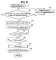
- a sample analyzer when interruption request for a reagent registration is issued by operating an interrupt/restart key during an analysis operation, a message indicating that sample dispensing is stopped is displayed on a display unit, and the operation of dispensing the sample in a sample cup into a cuvette is temporarily stopped. If a sample has already been dispensed into a cuvette when the interrupt/restart key is operated, a message indicating that reagent is able to be replaced is displayed on the display unit after dispensing a reagent into this cuvette.
- a plurality of reagent racks holding reagent are able to be removed to supplement or replace reagents during a measuring operation, and reagent information of the reagents held in the reagent racks is able to be updated during a measurement operation.
- Reagent is disposed overall in a square pattern by a plurality of reagent racks.
- the dispensing part that dispenses reagent is moved in the X-Y direction above an individual reagent that is to be the dispensing object among the reagents disposed in a square pattern by a plurality of reagent racks, suctions the target reagent, and is subsequently moved above a reagent tank whereupon the suctioned reagent is dispensed into the reaction tank.
- the dispensing part must be moved in the X-Y direction above the individual target reagent among the reagent arranged in a square pattern in order to suction the target reagent that is to be dispensed whenever the dispensing part suctions the target reagent. Accordingly, the dispensing part has a large movement range and the mechanism of the dispensing part is therefore complicated. The size of the overall apparatus is thus increased and the control of the apparatus becomes more complex.
- a first aspect of the present invention is a sample analyzer for analyzing a measurement sample prepared by a sample and a reagent, comprising: a rotatable first holding section for holding a first reagent container containing a first reagent and a second reagent container containing a second reagent circularly; a rotatable second holding section for holding a third reagent container containing a third reagent and a fourth reagent container containing a fourth reagent circularly, the second holding section being arranged concentrically relative to the first holding section; a dispenser for dispensing a reagent selected from the first to fourth reagents into a measurement sample container for preparing a measurement sample; analyzing means for analyzing the measurement sample; first receiving means for receiving an replacement instruction for replacement of at least one of the first to fourth reagent containers; second receiving means for receiving an order including a sample analysis item; and control means for controlling the dispenser so as to dispense the third reagent contained in the third reagent container held by
- a second aspect of the present invention is a method for analyzing a measurement sample prepared by a sample and a reagent, comprising steps of: (a) dispensing a sample into a measurement sample container for preparing a measurement sample;(b) receiving an replacement instruction for replacement of a first reagent container containing a first reagent, the first reagent container being held by a rotatable first holding section; (c) receiving an order including a sample analysis item which uses a second reagent contained in a second reagent container held by a rotatable second holding section which is arranged concentrically relative to the first holding section; (d) dispensing the second reagent contained in the second reagent container into the measurement sample container for preparing the measurement sample; and (e) analyzing the measurement sample.
- the embodiment of the sample analyzer 1 of the present invention optically measures and analyzes the amount and activity of specific substances found in blood related to coagulation and fibrinolysis, and uses blood plasma as a sample.
- such optical measurement (main measurement) of specimens are performed using the coagulation time method, synthetic substrate method, and immunoturbidity method.
- the coagulation time method used in the present embodiment detects and measures the change in the transmission light during the sample coagulation process.
- Measurement items include PT (prothrombin time), APTT (active partial thromboplastin time), and Fbg (fibrinogen content) and the like.
- Measurement items of the synthetic substrate method include ATIII and the like, and those of the immunoturbidity method include D-dimer, FDP and the like.
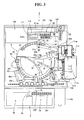
- the sample analyzer 1 is configured by a measuring unit 2, sample transporting unit 3 disposed on the front side of the measuring unit 2, and a control unit 4 which is electrically connected to the measuring unit 2.
- the measuring unit 2 is provided with a cuvette acceptor 5 for inserting a cuvette 200 (refer to Fig. 4), which is a sample container, when performing a measurement.
- the cuvette acceptor 5 is provided with a cover 5a that is able to be opened and closed, and a window 5b through which the interior of the cuvette insertion part 5 is able to be viewed. Furthermore, an emergency stop button 1a, and measurement start button 1b are provided on the front side of the cuvette acceptor 5.
- the cover 5a (refer to Fig.
- the emergency stop button 1a functions to stop a measurement during an emergency.
- the measurement start button 1b (refer to Fig. 1) is configured so as to start a measurement when the button is pressed. Thus, a user is able to start a measurement immediately after a cuvette 200 has been inserted. Starting and stopping of a measurement may also be accomplished by an operation performed by the control unit 4.
- the control unit 4 is configured by a personal computer 401 (PC), and includes a controller 4a, display 4b, and keyboard 4c, as shown in Figs. 1 and 2.
- the controller 4a functions to control the operations of the measuring unit 2 and transporting unit 3, and analyzes the optical information of samples obtained by the measuring unit 2.
- the controller 4a is configured by a CPU, ROM, RAM and the like.
- the display 4b is provided to display information relating to interference substances (hemoglobin, bilirubin, chyle (fats)) present in a sample, and analysis results obtained by the controller 4a.
- the controller 4a is mainly configured by a CPU 401a, ROM 401b, RAM 401c, hard disk 401d, reading device 401e, I/O interface 401f, communication interface 401g, and image output interface 401h.
- the CPU 401a, ROM 401b, RAM 401c, hard disk 401d, reading device 401e, I/O interface 401f, communication interface 401g, and image output interface 401h are connected by a bus 401i.
- the CPU 401a is capable of executing computer programs stored in the ROM 401b, and computer programs loaded in the RAM 401c.
- the computer 401 functions as the control unit 4 when the CPU 401a executes an application program 404a described later.
- the ROM 401b is configured by a mask ROM, PROM, EPROM, EEPROM or the like, and stores computer programs executed by the CPU 401a and data and the like used in conjunction therewith.
- the RAM 401c is configured by SRAM, DRAM or the like.
- the RAM 401c is used when reading the computer program recorded in the ROM 401b and on the hard disc 401d.
- the RAM 401c is further used as a work area of the CPU 401a when these computer programs are being executed.
- the hard disc 401d contains various installed computer programs to be executed by the CPU 401a such as an operating system and application programs and the like, and data used in the execution of these computer programs. Also installed on the hard disk 401d is the application program 404a used to calculate the presence and concentration of interference substances in the present embodiment.
- the reading device 401e is configured by a floppy disk drive, CD-ROM drive, DVD-ROM drive or the like, and is capable of reading the computer programs and data stored on a portable recording medium 404. Furthermore, the portable recording medium 404 may also store the application program 404a in the present embodiment; the computer 401 is capable of reading the application program 404a from the portable recording medium 404 and installing the application program 404a on the hard disk 401d.
- the application program 404a may be provided by the portable recording medium 404, it also may be provided from an external device connected to the computer 401 so as to be capable of communication over an electric communication line by means of the electric communication line (wire line or wireless).
- the application program 404a may be stored on the hard disk of a server computer connected to the internet, such that the computer 401a is able to access the server computer and download the application program 404a, and then install the application program 404a on the hard disk 401d.
- an operating system providing a graphical user interface, such as, for example, Windows (registered trademark) of Microsoft Corporation, U.S.A.
- Windows registered trademark
- the application program 404a of the present embodiment operates on such an operating system.
- the I/O interface 401f is configured by a serial interface such as a USB, IEEE1394, RS232C or the like, parallel interface such as SCSI, IDE, IEEE1284 or the like, analog interface such as a D/A converter, A/D converter or the like.
- the keyboard 4c is connected to the I/O interface 401f, such that a user is able to input data in the computer 401 using the keyboard 4c.
- the communication interface 401g is, for example, and Ethernet (registered trademark) interface.
- the computer 401 is able to transmit and receive data to and from the measuring unit 2 using a predetermined communication protocol via the communication interface 401g.
- the image output interface 401h is connected to the display 4b configured by an LCD, CRT or the like, such that image signals corresponding to the image data received from the CPU 401a is able to be output to the display 4b.
- the display 4b displays an image (screen) in accordance with the input image signals.
- the display 4b is capable of displaying a reagent placement screen 410 that displays the layout of reagents in the reagent preserving section 6, which is described later.
- the reagent placement screen 410 has a reagent placement display region 420, reagent information display region 430, and command display region 440.
- the reagent placement screen 410 is provided with a measurement start button 411 for starting the measurement process in the sample analyzer 1, and a measurement stop button 412 for stopping the measurement.
- the display 4b functions as a touch panel to allow selections and operations when a user directly touches a button or the like displayed on the reagent placing screen 410.
- the reagent placement display region 420 includes a plurality of first reagent display regions 421 for displaying the reagents disposed on a first reagent table 11 which is described later, and a plurality of second reagent display regions 422 for displaying the reagents disposed on a second reagent table 12 which also described later.
- the first reagent display region 421 includes a position display 421a for displaying the position of the reagent, reagent name display 421b for displaying the name of the reagent, and remainder display 421c for displaying the residual amount of the reagent.
- the second reagent display region 422 includes a position display 422a for displaying the position of the reagent, reagent name display 422b for displaying the name of the reagent, and remainder display 422c for displaying the residual amount of the reagent.
- the positions of the reagent displayed in the reagent name displays 421a and 422a are displayed when the barcode reader 350 reads the barcodes 311b and 312b of the first reagent container rack 310, and the barcodes 321b through 326b of the second reagent container rack 320, which are described later.
- the reagent names displayed in the reagent name displays 421b and 422b are displayed by referencing a special table based on the values of the barcodes 300a of the reagent container 300 read by the barcode reader 350. Moreover, the residual amount of the reagent displayed in the remainder displays 421c and 422c are displayed based on values calculated from the number of aspirations of the reagent and type of container that contains the reagent.
- the first reagent display region 421 is divided in two parts in each of the regions corresponding to the five first reagent container racks 310 (refer to Fig. 5) which are each capable of holding two reagent containers 300 disposed on the first reagent table 11 (refer to Fig. 5).
- the second reagent display region 422 s divided in six parts in each of the regions corresponding to the five second reagent container racks 320 (refer to Fig. 5) which are each capable of holding six reagent containers 300 disposed on the second reagent table 12 (refer to Fig. 5).
- reagent placement screen 410 it is possible to confirm on the reagent placement screen 410 how the reagents are placed, meaning at which positions on which reagent container rack (first reagent container rack 310 or second reagent container rack 320) and on which reagent table (first reagent table 11 or second reagent table 12).
- first reagent container rack 310 or second reagent container rack 320 When the first reagent container rack 310 or second reagent container rack 320 is not disposed on the first reagent table 11 or second reagent table 12, nothing is displayed in the first reagent display region 421 or second reagent display region 422.
- first reagent container rack 310 or second reagent container rack 320 is disposed on the first reagent table 11 or second reagent table 12, but the container rack does not hold a reagent container 300, only the position display 421a or position display 422a is displayed in the first reagent display region 421 or second reagent display region 422. This aspect is described more fully later.
- the attribute information (holder number, reagent name, use sequence, usable residual amount (usable amount), number of remaining tests, agitation requirement, lot number, type of reagent container, reagent expiration date, installation date and time and the like) of the specified reagent is displayed in the first reagent display region 421 or second reagent display region 422.
- a user is able to determine the replacement period of the reagent by the reagent attribute information.
- the command display region 440 includes a replace-add command button 440a for issuing instruction for the replacement or addition of reagent, edit button 440b for editing the reagent information, and reagent lot setting button 440c for manually entering the reagent lot.
- a first reagent container rack 310 or second reagent container rack 320 holding a reagent container 300 that contains a specified reagent is moved to a position at which it is able to be picked up from the sample analyzer 1 by selecting the replace-add command button 440a when a reagent has been specified.
- the first reagent display region 421 or second reagent display region 422, in which a reagent is not disposed, is specified, and the replace-add button 440a is selected.
- the first reagent container rack 310 or second reagent container rack 320 that does not accommodate reagent is moved to the pick up position.
- the sample transporting unit 3 functions to transport the rack 251 that holds a plurality (ten in the present embodiment) of test tubes that contain samples to the aspirating position 2a (refer to Fig. 3) of the measuring unit 2 to supply sample to the measuring unit 2. Furthermore, the transport device 3 has a rack set region 3a that accommodates the racks 251 that hold the test tubes 250 containing unprocessed specimens, and a rack receiving region 3b that accommodates the racks 251 that hold test tubes 250 containing processed specimens.
- the measuring unit 2 is capable of obtaining optical information related to a supplied sample by optically measuring the sample supplied from the transporting unit 3.
- a sample is dispensed from the test tube 250 disposed in the rack 251 of the transporting unit 3 into a cuvette 200 of the measuring unit 2, and is then optically measured.
- the measuring unit 2 includes a reagent storing part 6 and for storing reagent, and a reagent replacing part 7 for replacing or adding reagent.
- the measuring unit 2 has a sample dispensing drive part 80a, sample dispensing drive part 130a, first drive part 502, second drive part 503, first sensor 51, second sensor 52, reagent barcode reader 350, sample barcode reader 3c, first optical information obtaining part 90, second optical information obtaining part 140, and a controller 501 that is electrically connected to transporting unit 3, etc.
- the sample dispensing drive part 80a is provided with a stepping motor 80b that functions to raise, lower and rotate a sample dispensing arm 80 (refer to Figs. 3 and 5) which is described later, drive circuit (not shown in the drawings) for actuating the stepping motor 80b, and a pump (not shown in the drawing) for suctioning and dispensing sample.
- the reagent dispensing drive part 130a is provided with a stepping motor 130b that functions to raise, lower and rotate a reagent dispensing arm 130 (refer to Figs. 3 and 5) which is described later, drive circuit (not shown in the drawings) for actuating the stepping motor 130b, and a pump (not shown in the drawing) for suctioning and dispensing reagent.
- the first drive part 501 is provided with a first stepping motor (not shown in the drawing) that functions to rotate the first reagent table 11 which is described later, and a drive circuit (not shown in the drawing) for actuating the first stepping motor.
- the first reagent table 11 rotates an amount commensurate with the number of pulses of the drive pulse signals supplied from the controller 501 to the first drive part 502, then stops.
- the second drive part 503 is provided with a second stepping motor (not shown in the drawing) that functions to rotate the second reagent table 12 (refer to Fig. 5), and a drive circuit (not shown in the drawing) for actuating the second stepping motor.
- the second reagent table 12 rotates an amount commensurate with the number of pulses of the drive pulse signals supplied from the controller 501 to the second drive part 503, then stops.
- the controller 501 controls the rotational movement of each reagent table 11 and 12 by determining the amount of rotational movement from the origin positions of the reagent tables 11 and 12 by counting the number of pulses of the supplied drive pulse signals.
- the sensor 51 functions to detect the lock status of the first cover 30 (refer to Fig. 3) which is described later, and to transmit a lock signal to the controller 501 when the first cover 30 is locked.
- the sensor 52 functions to detect the lock status of the second cover 40 (refer to Fig. 3) which is described later, and to transmit a lock signal to the controller 501 when the second cover 40 is locked.
- the reagent barcode reader 350 functions to read each of the barcodes on the first reagent table 11 and second reagent table 12, and is disposed at a predetermined distance from the reagent storing part 6 in the vicinity of the side surface 21 of the reagent storing part 6 which is described later.
- the reagent barcode reader 350 is able to transmit and receive data to/from the controller 501, and has a drive circuit (not shown in the drawings) for controlling the ON/OFF condition of the reagent barcode reader 350.
- the position of the reagent barcode reader 350 is normally fixed.
- the sample barcode reader 3c functions to read the barcode adhered to the test tube 250 that contains a sample and is loaded in the rack 251 that is transported by the transporting unit 3, and is provided opposite the rack 251 that is transported by the transporting unit 3 and in the vicinity of the aspirating position 2a of the previously mentioned measuring unit 2.
- the sample barcode reader 3c is able to transmit and receive data to/from the controller 501, and has a drive circuit (not shown in the drawings) for controlling the ON/OFF condition of the reagent barcode reader 3c.
- the position of the sample barcode reader 3c is normally fixed.
- the first optical information obtaining part 90 and the second optical information obtaining part 140 function to obtain the optical information of samples, and are capable of transmitting and receiving data to/from the controller 501.
- the first optical information obtaining part 90 and the second optical information obtaining part 140 are described in detail later.
- the controller 501 is mainly configured by a CPU 501a, ROM 501b, RAM 501c, and communication interface 501d.
- the CPU 501a is capable of executing computer programs stored in the ROM 501b, and computer programs loaded in the RAM 501c.
- the ROM 501b stores the computer programs executed by the CPU 501a, and the data and the like used in the execution of the computer programs.
- the RAM 501c is used when reading the computer programs stored in the ROM 501b.
- the RAM 501c is further used as a work area of the CPU 501a when these computer programs are being executed.
- the communication interface 501d is connected to the control unit 4, and functions to transmit sample optical information to the control unit 4 and receive signals from the control unit 4.
- the communication interface 501d further functions to transmit commands from the CPU 501a to drive the various parts of the transporting unit 3 and measuring unit 2.
- the measuring unit 2 includes a reagent storing part 6 and for storing reagent, and a reagent replacing part 7 for replacing or adding reagent.
- the reagent storing part 6 is provided to store the reagent containers 300 that contained the reagent added to sample within the cuvette 200 at a low temperature (approximately 10 degrees Centigrade), and transport the reagent containers 300 in a rotary direction. Deterioration of the reagent is prevented by preserving the reagent at low temperature.
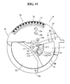
- the reagent storing part 6 includes a reagent transporting part 10 (refer to Figs. 4 and 5) for holding and moving reagent rotationally, and an outer wall 20 (refer to Fig. 3) provided to cover the perimeter and top of the reagent transporting part 10.
- the reagent transporting part 10 that holds the reagent is disposed in a cooled region formed by the outer wall 20, first cover 30 and second cover 40 of the reagent replacing part 7 which is described later.
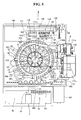
- the reagent transporting part 10 includes a circular first reagent table 11, and annular second reagent table 12 which is disposed on the outer side of the circular first reagent table to as to be concentric therewith, as shown in Fig. 5.
- the first reagent table 11 and second reagent table 12 accommodate, so as to be removable, the first reagent container racks 310 and second reagent container racks 320 that hold the reagent containers 300.
- the outer wall 20 is configured by a side surface 21 (refer to Fig. 4), a top surface 22 that is fixedly attached to the side surface 21 (refer to Fig. 3) , and a removable cover 23 (refer to Fig. 3) .
- the barcode reader 350 is disposed at a predetermined distance from the reagent storing part 6 in the vicinity of the side surface 21 (refer to Fig. 4) of the reagent storing part 6.
- the first reagent table 11 and second reagent table 12 are mutually and independently rotatable in both clockwise and counterclockwise directions.
- the first reagent container racks 310 and second reagent container racks 320 that hold the reagent containers 300 containing reagent are transported in a rotational direction by the first reagent table 11 and second reagent table 12.
- the reagent to be dispensed is able to thus be placed near the reagent dispensing arm 130 by transporting the reagent container 300 in a rotational direction when the reagent dispensing arm 130 is to dispense reagent in a manner described later.
- a heat-insulating material (not shown in the drawing) is mounted on the side surface 21 of the outer wall 20 to prevent the cool air within the reagent storing part 6 (cooled region) from escaping.
- a shutter 21a that is able to be opened and closed is provided at a position opposite the barcode reader 350 on the side surface 21 of the outer wall 20.
- the shutter 21a is configured so as to open only when the barcode reader 350 reads the barcode on the first reagent containers 310 and second reagent containers 320.
- the cool air within the reagent storing part 6 (cooled region) is prevented from escaping to the outside.
- the top surface 22 of the outer wall 20 includes three holes 22a, 22b, and 22c.
- Reagent stored in the reagent storing part 6 is aspirated by the reagent dispensing arm 130 through the three holes 22a, 22b, 22c.
- the hole 22a is positioned above the reagent container 300 held in the first reagent container rack 310.
- Reagent is aspirated from the reagent container 300 held in the first reagent container rack 310 through the hole 22a.
- the holes 22b and 22c are respectively positioned above the reagent containers 300 held in the front and the back row in the second reagent container table 320.
- Reagent is aspirated from the reagent containers 300 held in the front and the back row in the second reagent container table 320 through the holes 22b and 22c.
- a semicircular opening is formed in the reagent storing part 6 (cooled region) by removing the cover 23 together with the first cover 30 and second cover 40.
- the first reagent container rack 310 and second reagent container rack 320 are able to be positioned in the reagent storing part 6 through this opening when starting the measurement performed in the sample analyzer 1.
- the first reagent container rack 310 has five positions on the first reagent table 11.
- the reagent containers 300 are disposed in a ring in the five reagent container racks 310.
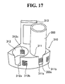
- the first reagent container rack 310 includes two holders 311 and 312 for holding reagent containers 300, slots 311a and 312a respectively provided on the front side of the holders 311 and 312, and one handle 313 provided so as to project upward.
- the holders 311 and 312 are round in shape when viewed on a plane, and are capable of holding the reagent container 300 when the cylindrical reagent container 300 is inserted.
- Reagent containers 300 that have an external diameter that is smaller than the internal diameter of the holders 311 and 312 are able to be held by the holders 311 and 312 by mounting an adapter (not shown in the drawing) in the holders 311 and 312.
- the first reagent container rack 310 further includes two types of racks formed to allow different combinations of internal diameters of the holders 311 and 312. A user may utilize reagent containers 300 of difference sizes by changing the type of rack. Barcodes 311b and 312b are provided on the front side of the outer surface of the holders 311 and 312, respectively, and barcodes 311c and 312c are provided on the inside surfaces of the holders 311 and 312, respectively.
- the slots 311a and 312a are provided to allow the barcode reader 350 to read the barcodes 311c and 312c, respectively.
- the handle 313 is held when removing the first reagent container rack 310 from the reagent storing part 6.
- the barcodes 311b and 312b include position information for identifying the position of the holders 311 and 312, respectively.
- the barcodes 311c and 312c include information indicating the presence/absence of a reagent container 300 hold in the holders 311 and 312 (no reagent container information).
- the barcode 300a of the reagent container 300 includes information for specifying the attribute information (holder number, reagent name, reagent container type, lot number, reagent valid period and the like) of the reagent contained in the reagent container 300. That is, the holder number is basically specified in the barcode 300a of the reagent container 300 read by the barcode reader 350. That is, the reagent name, reagent container type, lot number, reagent valid period and the like are basically specified in the barcode 300a of the reagent container 300 read by the barcode reader 350.
- the barcode 300a of the reagent container 300 is read and the barcode 311c is not read. That is, when the barcode 300a is read after the barcode 311b has been read by the barcode reader 350, the controller 4a recognizes via the barcode reader 350 that a reagent possessing reagent information is held in the holder 311. Furthermore, when the barcode 311c is read after the barcode 311b has been read by the barcode reader 350, the controller 4a recognizes that a reagent is not held in the holder 311.
- the controller 4a recognizes a reading error and a reading error message is displayed on the display 4b.
- the five second reagent container racks 320 are able to be accommodated in the second reagent table 12.
- the reagent containers 300 are disposed in a ring in the five reagent container racks 320.
- One location among the gaps between the five places of the mutually adjacent second reagent container racks 320 has a space larger than the spaces of the other four locations.
- the second reagent container rack 320 includes six holders 321 through 326 for holding reagent containers 300, slots 321a through 326a respectively provided on the front side of the holders 321 through 326, and one handle 327 provided so as to project upward.
- the holders 321 through 326 of the second reagent container rack 320 is circular, and capable of holding cylindrical reagent containers 300 inserted therein, similar to the first reagent container rack 310.
- the second reagent container rack 320 includes three types of racks formed so as to have respectively different combinations of internal diameters among the holders 321 through 326.
- the second reagent container rack 320 is capable of accommodating the same reagents as those accommodated in the first reagent container rack 310.
- Barcodes 321b and 322b are provided on both sides of the front row slot 321a.
- the barcodes 323b and 324b and barcodes 325b and 326b are respectively provided on both sides of slot 323a and slot 325a.
- the barcodes 321c through 326c are respectively provided on the inside surface of the holders 321 through 326.
- the barcodes 321b through 326b include position information for identifying the position of the holders 321 through 326.
- the barcodes 321c and 326c include information indicating the presence/absence of a reagent container 300 hold in the holders 321 through 326 (no reagent container information).
- the reagent information and no reagent container information read by the barcode reader 350 are stored on the hard disk 401d by the controller 4a with the corresponding position information.
- the information stored on the hard disk 401d is displayed on the reagent placement screen 410 on the display 4b via the controller 4a of the control unit 4.
- the barcodes 311b, 312b, and 321b through 326b display four-unit values.
- the first column has a value of either [A] or [B]; the value [A] indicates the reagent container 300 is disposed on the second reagent table 12, and the value [B] indicates the reagent container 300 is disposed on the first reagent table 11.
- the second column has a value of [1] to [5]; the values [1] through [3] respectively indicate the three shape types of the second reagent container rack 320, and the values [4] and [5] indicate the two shape types of the first reagent container rack 310.
- the third column has a value of [0] to [9] indicating the number of the first reagent container rack 310 or second reagent container rack 320.
- the fourth column has a value of either [1] or [2]; the values [1] and [2] respectively indicate the holder 311 and 312.
- the fourth column has a value of [1] to [6]; the values [1] through [6] respectively indicate the holders 321 through 326.
- the barcode values are displayed in the position display area 421a or 422a of the reagent display region (first reagent display region 421 or second reagent display region 422) of the reagent placement screen 410, as shown in Fig. 7.
- a barcode value [A15-6] represents the rack corresponds type [1] among the three types of racks that are able to be accepted in the second reagent table 12 (second reagent container rack 320), in the sixth holder (holder 326) of the fifth rack of the second reagent container racks 320.
- the reagent name and no reagent container information among the attribute information are displayed in the reagent name display area 421b and 422b of the first reagent display region 421 and the second reagent display region 422 in the reagent placement screen 410.
- the reagent name is displayed in the reagent name display area 421b or 422b when a reagent is placed, and nothing is displayed in the reagent name area 421b or 422b when a reagent is not placed.
- the reagent name [PT-TPC+] is placed at reagent position [A15-6], and no reagent id placed at the reagent position [A28-1] .
- the barcode reader 350 does not read a barcode when the reagent container rack itself is not placed, nothing is displayed in the first reagent display area 421 or second reagent display area 422 corresponding to the region of the missing first reagent container rack 310 or the second reagent container rack 320.
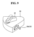
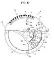
- the reagent replacing part 7 is provided near the center of the sample analyzer 1, as shown in Figs. 1 and 2.
- the reagent replacing part 7 includes a first cover 30 and second cover 40 respectively provided for the locking devices 31 and 41 so as to be removable, sensor 50 (refer to Figs. 13 and 14) for detecting the lock status of the first cover 30 and second cover 40, and an indicator 60 for alerting a user to the transport status of the first reagent table 11 and second reagent table 12, as shown in Figs. 8 through 14.
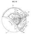
- the unlocked condition of the of the locking device 31 of the locking device 30 and the locking device 41 of the second cover 40 are shown in Fig. 13, and the locked condition of the locking device 31 of the first cover 30 and the locking device 41 of the second cover 40 are shown in Fig. 14.
- the first cover 30 is able to be removed when replacing the reagent containers 300 placed to the first reagent table 11 (first reagent container rack 310), as shown in Figs. 8 and 11.
- the first cover 30 has a fan-like configuration and is mounted above the first reagent table 11.
- the size and shape of the first cover 30 allow only a single first reagent container rack 310 to be removed when the first cover 30 has been removed.
- the locking device 31 of the first cover 30 is provided to lock the first cover 30 during normal use or after reagent replacement or addition has been completed, and is provided so that the controller 4a is aware when reagent replacement or addition has been completed in the first reagent table 11.
- the locking device 31 of the first cover 30 is configured by a handle 32 that is rotatable by a user so as to pivot on a rotating shaft 32a, relay member 33 for integratedly rotating the handle 32 to pivot on the rotating shaft 32a, locking member 34 capable of engaging with the relay member 33 and rotating on a rotating shaft 34a, and lock sensing member 35 for engaging the relay member 33 and rotating on a rotating shaft 35a.
- the locking member 34 is provided with a hook 34b on the end on the opposite side from the relay member 33.
- the locking member 35 is provided, at the end on the opposite side from the relay member 33, with a pressing piece 35b (refer to Fig.
- a cylindrical connector 6a is fixedly mounted to the center of the reagent storing part 6, and connects to the hook 34b of the hook member 34.
- the outer diameter of the cylindrical connector 6a is greater than the inner diameter of the hook 34b.
- a channel 6b having an outer diameter substantially the same as the inner diameter of the hook 34 is provided at a position corresponding to the hook 34b of the cylindrical connector 6a.
- the relay member 33 When the handle 32 is rotated in the arrow A direction on the rotating shaft 32a from the unlocked state shown in Fig. 13, the relay member 33 is also rotated in the arrow A direction on the rotating shaft 32a. Since the hook member 34 engages the relay member 33, the hook member 34 is rotated in the arrow B direction on the rotating shaft 34a in conjunction with the rotation of the relay member 33 in the arrow A direction. Therefore, the hook 34b of the hook member 34 engages the channel 6b of the cylindrical connecting part 6a and becomes locked.
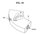
- the second cover 40 is able to be removed when replacing a reagent container 300 placed on the second reagent table 12 (second reagent container rack 320).
- the second cover 40 is mounted above the second reagent table 12 on the outer side of the first cover 30.
- the size and shape of the second cover 40 allow only a single second reagent container rack 320 to be removed when the second cover 40 has been removed.
- the locking device 41 of the second cover 40 is provided to lock the second cover 40 during normal use or after reagent replacement or addition has been completed, and is provided so that the controller 4a is aware when reagent replacement or addition has been completed in the second reagent table 12.
- the locking device 41 of the second cover 40 is configured by a handle 42 that is rotatable by a user so as to pivot on a rotating shaft 42a, bifurcated relay member 43 for integratedly rotating the handle 42 to pivot on the rotating shaft 42a, locking member 44 capable of engaging with the relay member 43 and rotating on a rotating shaft 44a, and lock sensing member 45 for engaging the relay member 43 and rotating on a rotating shaft 45a.
- the locking member 44 is provided with a convex lock 44b on the end opposite from the relay member 43 (refer to Fig. 10).
- the locking member 45 is provided, at the end on the opposite side from the relay member 43, with a pressing piece 45b (refer to Fig.
- a second cover mount 46 attached to the second cover 40 (refer to Figs. 13 and 14) is provided, a position corresponding to the lock 44b, with a connector hole 46a for connecting with the lock 44b.
- the relay member 43 is also rotated in the arrow C direction on the rotating shaft 42a. Since the hook member 44 engages the relay member 43, the hook member 44 is rotated in the arrow D direction on the rotating shaft 44a in conjunction with the rotation of the relay member 43 in the arrow C direction. Therefore, the hook 44b of the hook member 44 engages the connector hook 46a of the second cover mount 46 and becomes locked.
- the sensor 50 includes a first sensor 51 and second sensor 52 for respectively detecting the locked state of the first cover 30 and second cover 40.
- the first sensor 51 includes a microswitch 51a, and flat spring 51b.
- the second sensor 52 includes a microswitch 52a, and a flat spring 52b.
- the first sensor 51 is configured such that the microswitch 51a detects the locked state of the first cover 30 when the flat spring 51b is pressed by the pressing piece 35b of the locking device 31 of the first cover 30, as shown in Figs. 13 and 14. Specifically, the lock detecting member 35, which is engaged with the relay member 33, is rotated in the arrow E direction on the rotating shaft 35a by the relay member 33 which is rotated in the arrow A direction together with the handle 32 when the first cover 30 is being locked. Therefore, the microswitch 51a is pressed by the flat spring 51b of the first sensor 51 since the flat spring 51b of the first sensor 51 is engaged when the pressing piece 35b of the lock sensing member 35 is rotated in the arrow E direction.
- the locked condition of the first cover 30 is detected by the first sensor 51 since the lock 34b of the locking device 31 is engaged with the cylindrical connector 6a while in this condition.
- the first sensor 51 transmits a signal to the controller 4a that indicates the first cover 30 is locked when the locked status of the first cover 30 has been detected.
- the second sensor 52 is configured such that the microswitch 52a detects the locked state of the second cover 40 when the flat spring 52b is pressed by the pressing piece 45b of the locking device 41 of the second cover 40.
- the lock detecting member 45 which is engaged with the relay member 43, is rotated in the arrow F direction on the rotating shaft 45a by the relay member 43 which is rotated in the arrow C direction together with the handle 42 when the second cover 40 is being locked. Therefore, the microswitch 52a is pressed by the flat spring 52b of the second sensor 52 since the flat spring 52b of the second sensor 52 is engaged when the pressing piece 45b of the lock sensing member 45 is rotated in the arrow F direction.
- the locked condition of the second cover 40 is detected by the second sensor 52 since the lock 44b of the locking device 41 is engaged with the connector hole 46a of the second cover mount 46 while in this condition.
- the second sensor 52 transmits a signal to the controller 4a that indicates the second cover 40 is locked when the locked status of the second cover 40 has been detected.
- the indicator 60 includes three LED indicators 61, 62, and 63. As shown in Figs. 1 and 3, the three LED indicators 61, 62, and 63 are arranged in a row at predetermined distance in the vicinity of the second cover 40, and are visible to a user from outside the sample analyzer 1.
- the LED indicators 61, 62, and 63 are capable of emitting blue light or red light.
- the LED indicator 61 functions to alert the user that the first reagent container rack 310 corresponding to the reagent on the first reagent table 11 specified by the user on the reagent placement screen 410 has been moved to the pick up position at which the reagent is able to be replaced (below the first cover 30). Specifically, the LED indicator 61 emits a red light during the rotation of the first reagent table 11, and emits a blue light when the first reagent container rack 310 corresponding to the specified reagent on the first reagent table 11 has moved to the pick up position and stopped. Thus, the user is alerted to the timing with which to remove the first cover 30 in order to add or replace the reagent.
- the LED indicator 62 functions to alert the user that the second reagent container rack 320 corresponding to the reagent on the second reagent table 12 specified by the user on the reagent placement screen 410 has been moved to the pick up position at which the reagent is able to be replaced (below the second cover 40). Specifically, the LED indicator 62 emits a red light during the rotation of the second reagent table 12, and emits a blue light when the second reagent container rack 320 corresponding to the specified reagent on the second reagent table 12 has moved to the pick up position and stopped, similar to the LED indicator 61.
- the LED indicator 63 functions to alert the user of the operating status of the cuvette moving table 71 which is described later. That is, when measuring a predetermined substance, the LED indicator 63 alerts the user of the timing by which to remove the cover 73 (refer to Fig. 8) positioned above the cuvette moving table 71 in order to add or replace a special cuvette (not shown in the drawing) on the cuvette moving table 71.
- the LED indicator 63 emits a red light while the cuvette moving table 71 is rotating, and emits a blue light when the cuvette moving table 71 has stopped.
- the sample analyzer 1 automatically reads the barcode 300a of all reagent containers 300 held in the first reagent container racks 310 or second reagent container racks 320 that hold replaced reagent. Therefore, when, for example, a single reagent has been specified a command has been issued to replace the reagent, post replacement reagent placement is accurately displayed on the reagent placement screen 410 as if reagent other than the specified reagent has been replaced in the first reagent container rack 310 or second reagent container rack 320 in addition to the specified reagent.
- the measuring unit 2 is provided with a cuvette moving section 7, sample dispensing arm 80, first optical information obtainer 90, lamp unit 100, heater 110, cuvette moving section 120, reagent dispensing arm 130, second optical information obtainer 140, urgent sample section 150, fluid flow section 160, and cuvette supplying device 170.
- the cuvette moving section 170 functions to transport the cuvettes 20 to the various parts of the sample analyzer 1.
- the cuvette moving section 170 is configured by an annular cuvette moving table 71 disposed outside the annular second reagent table 12, a plurality of cylindrical cuvette holders 72 provided at predetermined intervals along the circumference of the cuvette moving table 71, and a cover 73 provided above the cuvette moving table 71 (refer to Fig. 8).
- the cuvette holders 72 are provided to each hold a single cuvette 200.
- the cover 73 is provided with a hole 73a through which reagent is dispensed to the cuvette 200 by the reagent dispensing arm 80 which is described later.
- a measurement sample is prepared by dispensing the reagent stored in the reagent storing part 6 and sample contained in the test tube 250 of the transporting unit 3 to the cuvette 200 held by the cuvette holder 72 of the cuvette moving table 71 (refer to Fig. 5).
- the sample dispensing arm 80 functions to aspirate sample contained in the test tube 250 transported to the aspirating position 2a by the transporting unit 3, and dispense the aspirated sample through the hole 73a into the cuvette 200 held by the cuvette holder 72 of the cuvette moving table 71.
- the first optical information acquiring section 90 is configured so as to acquire optical information from a specimen in order to measure the presence and concentration of interference substances (hemoglobin, bilirubin, chyle) in the specimen before adding reagent. Specifically, the presence and concentrations of interference substances are measured using four types of light (405 nm, 575 nm, 660 nm, 800 nm) among five types of light (340 nm, 405 nm, 575 nm, 660 nm, 800 nm) emitted from the lamp unit 100 which is described later.
- the 405 nm wavelength light is absorbed by chyle, hemoglobin, and bilirubin.
- chyle, hemoglobin, and bilirubin influence the optical information measured using light at a wavelength of 405 nm. Furthermore, light at a wavelength of 575 nm is absorbed by chyle and hemoglobin, although essentially is not absorbed by bilirubin. That is, chyle and hemoglobin influence the optical information measured using light at a wavelength of 575 nm. Light at wavelengths of 660 nm and 800 nm are absorbed by chyle, although essentially are not absorbed by bilirubin and hemoglobin. That is, chyle influences the optical information measured using light at wavelengths of 660 nm and 800 nm.
- Chyle absorbs light from the low wavelength region 405 nm to the high wavelength region 800 nm, with chyle absorbing more light at the 660 nm wavelength than at the 800 nm wavelength. That is, the optical information measured using light at the 800 nm wavelength is less influenced by chyle than optical information at the 660 nm wavelength.
- the acquisition of sample optical information by the first optical information obtainer 90 is performed before optically measuring (main measurement) the sample by the second optical information obtainer 140.
- the first optical information obtainer 90 obtains optical information from the sample within the cuvette 200 held by the holder 72 of the cuvette moving table 71.
- the first optical information obtainer 90 is electrically connected to the controller 4a of the control unit 4, and transmits data (optical information) obtained by the first optical information obtainer 90 to the controller 4a of the control unit 4.
- data optical information obtained by the first optical information obtainer 90 to the controller 4a of the control unit 4.
- the control unit 4 the light absorbance of the sample within the cuvette 200 is determined relative to the five kinds of light emitted from a beam splitter optical fiber 101, and the presence and concentrations of interference substances in the sample are analyzed by performing data analysis of the data from the first optical information obtainer 90.
- a determination is made as to whether or not to analyze optical information acquired by the second optical information obtainer 140 based on the presence and concentrations of interference substances in the sample.
- the lamp unit 100 is provided to supply light of five wavelengths (340 nm, 405 nm, 575 nm, 660 nm, 800 nm) to be used for the optical measurements performed by the first optical information obtainer 90 and the second optical information obtainer 140, as shown in Fig. 5. That is, a single lamp unit 100 is configured so as to be used jointly by the first optical information obtainer 90 and second optical information obtainer 140. The light of the lamp unit 100 is supplied to the first optical information obtainer 90 and the second optical information obtainer 140 by the beam splitter optical fiber 101 and beam splitter optical fiber 102, respectively.
- the heater 110 is an incubation plate 111, and is provided with ten concave cuvette holders 111a.
- the cuvette holders 111a are each capable of holding a single cuvette 200, and function heat the sample within the cuvette 200 to approximately 37 degrees Centigrade by holding the cuvette 200 containing the dispensed sample for several minutes in the cuvette holder 111a. After the sample has been heated by the heater 110, reagent dispensing and measuring are performed within a set time. Thus, deterioration of the sample and the measurement sample prepared from the sample and reagent is prevented, and measurement results are stabilized.
- the cuvette moving section 120 is provided to move the cuvettes 200 among the cuvette moving section 70, heater 110, and second optical information obtainer 140.
- the cuvette moving section 120 includes a catcher 121 for holding the cuvette 200, and a drive part 122 for moving the catcher 121.
- the catcher 121 is movable within a moving range 120a by means of the drive force of the drive part 122, and moves the cuvette 200 among the cuvette moving section 70, heater 110, and the measurement feeder 141 second optical information obtainer 140.
- the catcher 121 is provided with an oscillating function so as to be capable of agitating the reagent and sample within the cuvette 200 by oscillating the cuvette 200 while the cuvette 200 is held in the catcher 121.
- the reagent dispensing arm 130 is provided to mix the reagent in the sample within the cuvette 200 by dispensing the reagent within the reagent container 300 placed in the reagent storing part 6 to the cuvette 200, as shown in Figs. 3 through 5. Specifically, reagent is aspirated through either the hole 22a, 22b, or 22c of the outer wall 20 of the reagent storing part 6, the cuvette 200 is heated (37 degrees Centigrade), then removed from the cuvette holder 111a of the heater 110 and held by the catcher 121, whereupon the aspirated reagent is dispensed to the cuvette 200.
- the pipette part of the reagent dispensing arm 130 is provided with a heating function, and heats the aspirated reagent momentarily to approximately 37 degrees Centigrade. That is, the reagent, which has been stored at low temperature (approximately 10 degrees Centigrade) in the reagent storing part 6, is heated to approximately 37 degrees Centigrade by the reagent dispensing arm 130, and then is mixed with the sample which has also been heated to 37 degrees Centigrade. Thus, a measuring sample is prepared by adding reagent to a sample that has already been optically measured by the first optical information obtainer 90.
- the dispensing operation of the dispensing reagent by the reagent dispensing arm 130 from the reagent table that holds the specified reagent is suspended.
- the reagent dispensing arm 130 suspends the dispensing operation of the dispensing reagent from the table holding the specified reagent, and does not suspend the dispensing operation of the dispensing reagent hold on the other reagent table.
- the reagent dispensing arm 130 stops the dispensing operation after completing the dispensing operation of the dispensing reagent to the sample being heated by the heater 110 and the sample already dispensed when reagent replacement was specified (the sample awaiting the reagent dispensing).
- the sample already dispensed when the reagent replacement was instructed is heated by the heater 110, and is measured within a set time after heating.
- the sample being heated in the heater 110 when the reagent replacement was instructed is also measured within a set time after heating.
- the second optical information obtainer 140 functions to obtain optical information from the measurement sample.
- the second optical information obtainer 140 is configured by a cuvette feeder 141, and sensor 142 disposed below the cuvette feeder 141, as shown in Fig. 5.
- the sensor 142 of the second optical information obtainer 140 is capable of optically measuring (main measurement) of a measurement sample within a cuvette 200 under a plurality of conditions.
- the second optical information obtainer 140 is electrically connected to the controller 4a of the control unit 4, and transmits data (optical information) obtained by the second optical information obtainer 140 to the controller 4a of the control unit 4.
- the control unit 4 analyzes the data (optical information) received from the second optical information obtainer 140 based on the analysis result of the already obtained data (optical information) from the first optical information obtainer 90.
- the 660 nmwavelength light emitted from the beam splitter optical fiber 102 is used as the main wavelength when measuring Fbg (fibrinogen content), PT (prothrombin time), and APTT (active partial thromboplastin time).
- the 800 nm wavelength light is a sub wavelength used when measuring Fbg, PT, and APTT.
- the 405 nm wavelength is used for measuring ATIII, which is a measurement item in the synthetic substrate method, and 800 nm wavelength light is used to measure D dimer and FDP, which are measurement items in the immunoturbidity method.
- the wavelength for measuring platelet coagulation is 575 nm.
- the urgent sample section 150 is provided for the analysis and processing for samples requiring urgent attention, as shown in Figs. 3 through 5.
- the urgent sample section 150 is configured so as to allow an urgent sample to interrupt an on-going sample analysis process of a sample supplied from the transporting unit 3.
- the fluid flow section 160 is provided to supply a fluid such as washing fluid to nozzles provided in each dispensing arm (sample dispensing arm 800 and reagent dispensing arm 130) during the shutdown process of the sample analyzer 1.
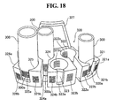
- the cuvette supplying device 170 is capable of sequentially supplying a plurality of cuvettes 200 directly loaded by the user to the cuvette transporting section 70. As shown in Figs. 3 through 5, the cuvette supplying device 170 includes a first hopper 171a, second hopper 171b that is smaller than the first hopper 171a and supplied cuvettes 200 from the first hopper 171a, two guide plates 172 for supplying cuvettes 200 from the second hopper 171b, support table 173 disposed below the bottom end of the two guide plates 172, and catchers 174 provided at predetermined spacing from the support table 173.
- the cuvettes 200 within the first hopper 171a move through the second hopper 171b, which is smaller than the first hopper 171a, and fall from the top of the two guide plates 172 toward the support table 173.
- the support table 173 functions to rotate the cuvettes 200 that have smoothly dropped along the guide plates 172 to a position at which the cuvette 200 is able to be grabbed by the catcher 174.
- the catcher 174 is provided to supply to the cuvette transporting section 70 those cuvettes 200 which have been moved by the support table 173.
- the measuring unit 2 is provided with a disposal hole 181 for disposing of the cuvettes 200 (refer to Figs. 3 and 5), and a waste box 182 disposed below the disposal hole 181 at a predetermined distance from the previously mentioned catcher 174.
- the catcher 174 disposes of the cuvette 200 on the cuvette transporting table 71 of the cuvette transporting section 70 through the disposal hole 181 (refer to Figs. 3 and 5) and into the waste box 182. That is, the catcher 174 both supplies and disposes of the cuvettes 200.
- the sample analyzer 1 is initialized by switching ON the respective power sources of the measuring unit 2 and control unit 4 of the sample analyzer 1 shown in Fig. 4. Thus, an operation is performed to return the devices for moving the cuvettes 200 and each dispensing arm (sample dispensing arm 80 and reagent dispensing arm 130) to their initial positions, and the software stored in the controller 4a of the control unit 4 is initialized.
- the transporting unit 3 shown in Fig. 5 moves the rack 251 loaded with test tubes 250 containing samples.
- the rack 251 at the rack placement region 3a is moved to a position corresponding to the aspirating position 2a of the measuring unit 2.
- a predetermined amount of the sample is aspirated from the test tube 250 by the sample dispensing arm 80. Then, the sample dispensing arm 80 is moved above the cuvette 200 held on the cuvette transporting table 71 of the cuvette transporting section 70. Thereafter, part of the sample is allocated into the cuvette 200 by discharging sample from the dispensing arm 80 into the cuvette 200 on the cuvette transporting table 71.
- the cuvette transporting table 71 is then rotated, and the cuvette 200 to which the sample was dispensed is moved to a position at which measurements are able to be performed by the first optical information obtainer 90.
- optical information is obtained from the sample when the first optical information obtainer 90 optically measures the sample.
- data which is composed of electrical signals derived from the five types of light (340 nm, 405 nm, 575 nm, 660 nm, 800 nm) transmitted through the sample within the cuvette 200 held by the cuvette holder 72 (refer to Fig. 5) of the cuvette transporting table 71, are transmitted to the controller 4a of the control unit 4.
- optical information (first optical information) is obtained from the sample when the first optical information obtainer 90 optically measures the sample.
- the controller 4a of the control unit 4 calculates the light absorption of the sample using the received data (first optical information), and calculates the presence and concentration of the interference substances (chyle, hemoglobin, bilirubin) in the sample, using the received data (first optical information). Specifically, the controller 4a of the control unit 4 calculates the light absorption of the sample based on the optical information (first optical information) obtained using four types of light (405 nm, 575 nm, 660 nm, 800 nm) emitted from the lamp unit 100, and stores the light absorption in the RAM 401c.
- a threshold value for example, 2.0
- the cuvette 200 is moved from the cuvette transporting table 71 to the heater 110 by the cuvette transporting section 120. Then, the cuvette 200, which contains sample that has been heated to approximately 37 degrees Centigrade by the heater 110, is grabbed by the catcher 121 of the cuvette transporting section 120. While the cuvette 200 is held by the catcher 121, the reagent dispensing arm 130 is actuated and the reagent within the reagent container 300 placed on the reagent table (first reagent table 11 or second reagent table 12) is added to the cuvette 200.
- the sample and reagent within the cuvette 200 are then agitated by the oscillation function of the catcher 121. Thus, a measurement sample is prepared.
- the cuvette 200 containing the measurement sample is then directly moved to the cuvette feeder 141 of the second optical information obtainer 140.
- the sensor 142 of the second optical information obtainer 140 obtains optical information (second optical information) from the measurement sample by optically measuring (main measurement) the measurement sample within a cuvette 200 under a plurality of conditions. Specifically, light is first emitted from the beam splitter optical fiber 102 of the lamp unit 100 toward the cuvette 200 of the cuvette feeder 141. Five different wavelength of light (340 nm, 405 nm, 575 nm, 660 nm, 800 nm) are emitted from the beam splitter optical fiber 132. Thus, data are obtained which are electrical signals corresponding to the light of each wavelength that was emitted from the beam splitter optical fiber 132 and passed through the cuvette 200 and the measurement sample within the cuvette sample.
- optical information second optical information
- optical information (second optical information) is obtained from the sample when the second optical information obtainer 140 optically measures the sample.
- the sample measurement item is an item using the coagulation time method such as PT, APTT, Fbg or the like
- optical information (second optical information) is obtained from the measurement sample by the second optical information obtainer 140.
- the light absorption at the sub wavelength calculated from the first optical information measured by the first optical information obtainer 90 is greater than the threshold value, it is determined that analysis with high reliability is difficult due to the excessive influence of interference substances (bilirubin, hemoglobin, and chyle) in the sample, and therefore the main measurement is terminated.
- interference substances bilirubin, hemoglobin, and chyle
- the determination that highly reliable measurement is difficult occurs, for example, when light is blocked from passing through the sample due to the presence of large quantities of interference substances in the sample detected by the first optical information obtainer 90, such that the transmittance light passing through the sample is essentially undetectable.
- the second optical information of the measurement sample measured at the main wavelength is transmitted to the controller 4a of the control unit 4 from among the plurality of the second optical information measured by the second optical information obtainer 140 and analyzed by an application program 404a installed on the hard disk 401d of the controller 4a.
- the controller 4a which has received the second optical information acquired at the main wavelength, outputs the analysis result based on this second optical information.
- the second optical information of the measurement sample measured at the sub wavelength is transmitted to the controller 4a of the control unit 4 from among the plurality of the second optical information measured by the second optical information obtainer 140 and analyzed by an application program 404a installed on the hard disk 401d of the controller 4a.
- the sample measurement item is PT
- the second optical information measured using the light of the main wavelength 800 nm is transmitted to the controller 4a of the control unit 4.
- the controller 4a which has received the second optical information acquired at the sub wavelength, outputs the analysis result based on this second optical information.
- the obtained analysis result is displayed on the display 4b of the control unit 4. This completes the analysis of a sample by the sample analyzer 1.
- Fig. 21 is a flow chart illustrating the flow of the measuring process of the controller 501 of the measuring unit 2 and the controller 4a of the control unit 4 in the sample analyzer 1. The flow of the measuring process of the controller 501 and controller 4a of the sample analyzer 1 of the present embodiment is described below with reference to Figs. 1, 3, 7, and 21.
- the controller 501 When the power source (not shown in the drawing) of the measuring unit 2 is turned ON, the controller 501 is initialized (programinitialization) and an operation check is performed of each part of the measuring unit 2 in step S1.
- the controller 4a When the power source (not shown in the drawing) of the control unit 4 is turned ON, the controller 4a is initialized (program initialization) in step S11.
- the controller 501 requests an initialization completed signal indicating the initialization has been completed from the controller 4a; when this initialization completed signal is received, the barcode reader 350 is controlled so as to read the barcodes of all reagents and reagent racks placed in the reagent storing part 6.
- the read barcode information is transmitted from the controller 501 to the controller 4a, and stored on the hard disk 401d of the controller 4a.
- step S12 the menu screen (not shown in the drawing) is displayed on the display 4b, the user presses the start button displayed on the menu screen, and a measurement start signal is transmitted from the controller 4a to the controller 501 in step S13.
- the start button is not pressed in step S12, the process continues to step S17.
- step S2 a determination is made by controller 501 as to whether or not a measurement start signal has been received; the process continues to step S3 when it is determined that a measurement start signal has been received, and the process continues to step S6 when it is determined that a measurement start signal has not been received.
- step S3 a process is performed to dispense reagent to the sample in the cuvette 200.
- step S4 the sample to which the reagent was dispensed is measured by the first optical information obtainer 90 and the second optical information obtainer 140, then, the measurement results are transmitted from the controller 501 to the controller 4a in step S5.
- step S14 a determination is made by the controller 4a as to whether or not the measurement results have been received; the process continues to step S15 when the measurement results have been received, and the process moves to step S17 when the measurement results have not been received.
- step S15 the measurement results are analyzed by the controller 4a, and these analysis results are stored on the hard disk 401d in step S16.
- step S17 the controller 4a determines whether or not there is a display command to display the reagent placement screen 410 (whether or not the reagent button (not shown in the drawing) has been pressed on the main menu to display the reagent placement screen) ; the process advances to step S18 when there is a display command to display the reagent placement screen 410, and the process advances to step S22 when there is not a display command to display the reagent placement screen 410.
- step S18 the controller 4a displays the reagent placement screen 410.
- the controller 4a displays the necessary information in the first reagent display region 421, second reagent display region 422, and reagent information display region 430 in the reagent placement screen 410 based on the barcode information read in step S1. (refer to Fig. 7).
- step S19 the controller 4a determines whether or not a replacement reagent has been specified on the reagent placement screen 410 shown in the display 4b which has a touch panel function.
- the reagent specification is described in detail below. That is, the user first confirms the placement of the reagent by referencing the reagent placement display region 420 of the reagent placement screen 410 shown in Fig. 7. The user selects an optional reagent with a finger by directly touching the first reagent display region 421 or second reagent display region 422 that displays the reagent among a plurality of first reagent display regions 421 and second reagent display regions 422.
- the user selects either the first reagent display region 421 or second reagent display region 422 that displays the selected reagent to be replaced.
- the process advances to step S20 when the controller 4a has determined there is a reagent specification in step S19, and the process advances to step S22 when the controller 4a determines that no reagent has been specified.
- the reagent [PT-TPC+] at reagent position [A15-6] is specified, and the attribute information of reagent [PT-TPC+] is displayed in the reagent information display region 430.
- step S20 When it is determined in step S20 that reagent replacement has been instructed, a reagent replacement signal is transmitted from the controller 4a to the controller 501 in step S21. Thereafter, the controller 4a performs the reagent replacement process in step S22. When it is determined in step S20 that reagent replacement has not been instructed, the process continues to step S23.
- step S23 the controller 4a determines whether or not shutdown has been instructed (whether or not the shutdown button (not shown in the drawing) on the menu screen has been pressed); the process continues to step S24 when shutdown has been instructed, and the process returns to step S12 when shutdown has not been instructed.
- step S24 a shutdown signal is transmitted from the controller 4a to the controller 501, the control unit 4 shuts down and the process ends.
- step S6 the controller 501 determines whether or not a reagent replacement signal has been received; the process continues to step S7 when it is determined that a reagent replacement signal has been received, and the process continues to step S8 when it is determined that a reagent replacement signal has not been received.
- step S7 the controller 501 performs the reagent replacement process.
- step S8 a determination is made as to whether or not a shutdown signal has been received; the process advances to step S9 when a shutdown signal has been received, and the process returns to step S2 when a shutdown signal has not been received.
- step S9 the measuring unit 2 shuts down and the process ends.
- steps S3, S4, and S7 are parallel processes and are performed in parallel.
- steps S15, S18, and S22 are parallel processes and are performed in parallel.
- Fig. 22 is a flow chart illustrating the details of the reagent replacement process of the controller 4a executed in step S22 of the flow chart shown in Fig. 21.
- Fig. 23 is a flow chart illustrating the details of the reagent replacement process of the controller 501 executed in step S7 of the flow chart shown in Fig. 21.
- the flows of the reagent replacement processes performed by the controller 4a and controller 501 of the sample analyzer 1 of the present embodiment are described below referring to Figs. 3, 7, 22, and 23.
- step S41 of Fig. 23 the controller 501 determines whether or not there is a sample awaiting reagent dispensing which uses the reagent on the reagent table that includes racks holding specified reagent (hereinafter referred to as "replacement reagent table"); if there is a sample awaiting reagent dispensing which uses the reagent on the reagent replacement table when the reagent replacement signal has been received, the reagent is dispensed to the sample in step S42. Reagent is dispensed from the reagent replacement table to all samples awaiting reagent dispensing which use reagent on the reagent replacement table by repeating steps S41 and S42.
- reagent is dispensed to the samples prior to executing reagent replacement.
- Reagent must be dispensed after a predetermined time has elapsed once a sample has been dispensed to the cuvette 200 and measurement has been started, and if that sequence does not happen properly, the sample is not able to be used for measurement and must be scrapped. Accordingly, samples for which measurement has started (samples awaiting reagent dispensing) must be subj ected to predetermined processing and measurements must be completed without interruption.
- the controller 501 executes the steps subsequent to step S43 to perform the reagent replacement operation when there are no samples which use reagent from the reagent replacement table among the samples awaiting reagent dispensing when reagent replacement has been instructed. That is, when there are no samples awaiting reagent dispensing, or all samples use reagent from the reagent that is not the reagent replacement table, the reagent replacement operation is able to be performed since there is no need to access the reagent replacement table.
- step S43 the controller 501 rotates the reagent replacement table and move the first reagent container rack 310 or second reagent container rack 320 holding the specified reagent to the pick up position (below the first cover 30 or second cover 40) by controlling the first drive part 502 and second drive part 503.
- the controller 501 issues a movement command to the drive circuit of the reagent replacement table.
- the drive circuit sets a reagent replacement flag in an internal status register.
- the reagent replacement status is set ON for the reagent replacement table that includes the reagent specified by the user for replacement. Either the reagent replacement status for the first reagent table 11 or the reagent replacement status for the second reagent replacement table 12 is set ON.
- the controller 501 transmits a movement completion signal to the controller 4a that indicates the reagent container rack holding the specified reagent has moved to the pick up position in step S44.
- the controller 501 determines the amount of rotational movement of each reagent table 11 and 12 from the origin position of the first reagent table 11 and second reagent table 12 by counting the number of pulses of the pulse drive signals supplied to the first drive part 502 and second drive part 503. Therefore, the controller 501 recognizes that the first reagent table 11 and second reagent table 12 have moved to the pick up position by the amount of movement from the origin position, and generates a movement completion signal based on this recognition.
- the controller 4a determines whether or not the movement completion signal has been received in step S31 of Fig. 22.
- step S33 the movement completion signal has been received
- the user is indicated that the reagent container rack holding the specified reagent has been moved to the pick up position in step S32.
- the user is indicated that the reagent container rack that holds the specified reagent has been moved to the pick up position.
- a lock release signal is transmitted from the lock sensor of the cover to the controller 501, and in step S45 the controller 501 determines whether or not the cover lock has been released.
- the cover lock release operation entails the user rotating the handle 32 of the first cover 30 in the opposite direction to the arrow A direction (refer to Fig. 13) to unlock the first cover 30.
- the user rotates the handle 42 of the second cover 40 in the opposite direction to the arrow C direction (refer to Fig. 13).
- the determination that the lock has been released is performed as follows.
- the reagent replacement operation performed by the user entails the user removing either the unlocked first cover 30 or unlocked second cover 40, and thereafter grasping and removing the handle 313 or 327) of the reagent container rack at the pick up position (below the first cover 30 or second cover 40). Then, the user replaces the reagent container 300 containing the specified reagent with a new reagent container 300 containing fresh reagent. Subsequently, the reagent container rack holding the replaced reagent is returned to the pick up position, and the user attaches and locks the first cover 30 or second cover 40.
- the cover locking operation entails the user rotating the handle 32 of the first cover 30 in the arrow A direction (refer to Fig. 13) to lock the first cover 30. To lock the second cover 40, the user rotates the handle 42 of the second cover 40 in the arrow C direction (refer to Fig. 13).
- a lock signal is transmitted from the lock sensor of the cover to the controller 501, and in step S46 the controller 501 determines whether or not the cover is locked.
- the determination of whether or not the cover is locked in step S46 is performed as follows.
- the microswitch 51a of the first sensor 51 or the microswitch 52a of the second sensor 52 is pressed, and the first sensor 51 or second sensor 52 transmits a detection signal to the controller 501.
- the cover is locked.
- step S47 When the controller 501 has determined in step S46 that the first cover 30 or second cover 40 is locked, a barcode reading operation is performed in step S47.
- the controller 501 controls the first reagent container table 11 or second reagent container table 12, and the barcode reader 350 so as to have the barcode reader 350 read the barcodes of the first reagent container rack 310 or second reagent container rack 320 holding the replaced reagent.
- the barcode 321b identifying the position information is initially read while the second reagent table 12 is rotated in the arrow G direction (counterclockwise direction). Thereafter, the barcode 300a identifying the reagent information or barcode 321c identifying absent container information is read, and subsequently the barcode 322b identifying position information is read. In this way the position information (barcodes 321b through 326b), and reagent information corresponding to the position information (barcode 300a) or absent container information (barcodes 321c through 326c) are alternately read.
- the second reagent table 12 When reading the barcodes 300a, and 311b through 312b or 311c through 312c of the first reagent container rack 310 and reagent containers 300 held in the first reagent rack 310, the second reagent table 12 is first rotated to have the gap 12a of the second reagent table 12 reach the position opposite the barcode reader 350. Thereafter, the barcode reader 350 alternately reads the position information (barcodes 311b through 312b), reagent information corresponding to the position information (barcode 300a), and absent container information (barcodes 311c through 312c) while the first reagent table 11 is rotating in the arrow G direction (counterclockwise direction) through the gap 12a (refer to Fig.
- the read position information, and reagent information corresponding to the position information or absent container information are transmitted to the controller 501 and stored in RAM 501c.
- step S48 the controller 501 transmits the barcode reading information stored in the RAM 501c to the controller 4a.
- step S33 the controller 4a determines in step S33 whether or not the barcode reading information has been received.
- the controller 4a determines that the barcode reading information has been received in step S33, the barcode reading information is stored on the hard disk 401d in step S34.
- step S35 the controller 4a refers to the reagent master table, reagent lot master table, and container master table to obtain detailed information such as reagent name, type of container, lot number, and valid period and the like for all reagents in the reagent racks holding replaced reagent based on the barcode reading information (read position information, reagent information corresponding to the position information or absent container information) stored on the hard disk 401d.
- step S36 the controller 4a displays the detailed information including position information, obtained reagent name, container type, lot number, and valid period in the first reagent display region 421 or second reagent display region 422 and reagent display region 430 of the reagent placement screen 410.
- Fig. 24 is a flow chart illustrating the details of the dispensing process of the controller 501 executed in step S3 of the flow chart shown in Fig. 21.
- the flow of the dispensing process performed by the controller 501 of the sample analyzer 1 of the present embodiment is described below referencing Figs. 3, 5, and 21.
- step S51 the controller 501 controls the sample barcode reader 3c to read the barcode adhered to the test tube 250 containing the sample transported by the transporting unit 3.
- step S52 the controller 501 obtains an order based on the read barcode information, and the process continues to step S53.
- step S53 the controller 501 determines whether or not the reagent replacement status has been turned ON for the first reagent table 11 or second reagent table 12. This process is performed by confirming the internal status registers of the drive circuit of the replacement reagent table by controller 501.
- step S53 a determination is made that the reagent replacement status is turned ON for either the first reagent table 11 or the second reagent table 12, the process continues to step S54.
- step S56 When it has been determined in step S53 that neither reagent replacement status has been turned ON, the process continues to step S56.
- the order is described below.
- the order is information including the analysis items associated with the information specifying the sample.
- the order may be recorded on the host computer (not shown in the drawing) connected to the control unit 4, and is able to be stored manually by the user in the control unit 4.
- the control unit 4 After the sample barcode has been read, the control unit 4 searches the orders stored in the control unit 4 and obtains a matching order using the sample ID as a key search term to the host computer.
- the order obtained by the control unit 4 is transmitted from the controller 4a of the control unit 4 to the controller 501 of the measuring unit 2, and the controller 501 obtains the order.
- step S56 the controller 501 controls the sample dispensing drive part 80a in accordance with the order, the sample contained in the test tube 250 transported by the transporting part 3 is aspirated by the sample dispensing arm 80, and the aspirated sample is dispensed into a cuvette 200 held by the cuvette holder 72 of the cuvette transporting table 71.
- step S57 the controller 501 controls the reagent dispensing drive part 130a, and the reagent is aspirated through the holes 22a, 22b, or 22c of the outer wall 20 of the reagent storing part 6 by the reagent dispensing arm 130, and the aspirated reagent is dispensed into a cuvette 200 that has been heated.
- step S54 determines whether or not the reagent analysis items specified in the order use a reagent held on the reagent replacement table.
- step S54 determines whether or not the reagent analysis items specified in the order use a reagent held on the reagent replacement table.
- steps 53 through 55 are repeated until it has been determined that the analysis items specified in the order do not use a reagent from the reagent replacement table.
- steps S56 and S57A are sequentially executes for deferred order when it has been determined that the analysis items specified in an obtained order do not use a reagent from the reagent replacement table.
- dispensing is suspended from the reagent table that includes the reagent specified for replacement, and dispensing is executed from the reagent table that does not include reagent specified for replacement.
- Reagent replacement is performed in the above manner in the present embodiment.
- the present embodiment described above provides a rotatable first reagent table 11 on which reagent can be placed in a ring-like pattern, a rotatable second reagent table 12 that is provided so as to be concentric with the first reagent table 11 and on which reagent can also be placed in a ring-like pattern, and a reagent dispensing arm 130 for dispensing reagent placed on the first reagent table 11 and second reagent table 12, such that a reagent that is to be dispensed by the reagent dispensing arm 130 is able to be brought near the reagent dispensing arm 130 by rotating the first reagent table 11 or second reagent table 12.
- the mechanism of the reagent dispensing arm 130 is able to therefore be simplified since the reagent dispensing arm 130 is able to dispense reagent without moving to the placement location of an individual reagent.
- This arrangement also avoids complexity of the control device and enlarging the size of the overall apparatus that arises when the reagent dispensing arm 130 has a complex mechanism.
- operations for dispensing of reagent are suspended from the reagent table on which the specified reagent is placed, and operations for dispensing of reagent are continued from the reagent table that does not hold the specified reagent.
- reagent is able to be replaced without stopping the measurement process.
- the specified reagent when replacement of reagent placed on the reagent table has been specified from the reagent table on which the reagent to be dispensed is placed, the specified reagent is moved to the pick up position after the reagent dispensing operation has been completed for the sample in an on-going measuring process from the reagent table on which the specified reagent is placed.
- reagent is able to be replaced without stopping the measurement process even when reagent replacement has been instructed during an on-going measuring process.
- dispensing reagent is able to continue from the reagent table that does not hold the specified reagent during reagent replacement even when reagent placed on the same reagent table has been specified for replacement during a reagent dispensing operation from the reagent table holding the specified reagent by having the first reagent table 11 and second reagent table 12 capable of holding the same reagents.
- the measurement operation need not be suspended.
- the reagent information of the replaced reagent is able to be automatically obtained after the reagent replacement, and the suspended dispensing operation is able to be automatically restarted by obtaining the reagent information of the replaced reagent and thereafter restarting the suspended dispensing operation from the reagent table holding the specified reagent.
- the replacement operation is thus simplified since there is no need to instruct restarting the suspended dispensing operation or obtaining reagent information of the replaced reagents collateral to the reagent replacement.
- reagents are managed simply by means of reagent information and reagent position information stored on the hard disk 401d by having the hard disk store the obtained reagent information and correlating the position information indicating the position of the replaced reagent.
- reagent replacement is able to be performed in reagent rack units by providing the first reagent table 11 and second reagent table 12 so as to be capable of respectively accommodating five rack units of the first reagent container racks 310 and second reagent container racks 320 that respectively hold two and six reagent containers 300.
- the reagent container 300 containing the specified reagent has been moved to the pick up position when replacement of a reagent has been instructed during a measuring operation, and the first cover 30 and second cover 40 have been locked by the locking device 31 and 41 after the reagent has been replaced, the reagent is able to be easily replaced from the pick up position by restarting the suspended dispensing operation.
- the reagent replacement operation is able to be simplified since the suspended dispensing operation is restarted by locking the first cover 30 and second cover 40 without specially instructing that the suspended dispensing operation be restarted.
- reagent replacement has been used as an example in the above described embodiment, the present invention is not limited to this example inasmuch as reagent may also be added.
- sequence of adding reagent is described below.
- either the first reagent display region 421 or the second reagent display region 422, which correspond to either the holders 311 and 312, or holder 321 through 326 holding the reagent to be added, is specified in step S19 of the present embodiment. Details of the specification of the reagent display region when adding reagent are described below. That is, the user first confirms the placement of the reagent by referencing the reagent placement display region 420 of the reagent placement screen 410 shown in Fig. 7.
- the user directly places a finger on either the first reagent display region 421 or second reagent display region 422 corresponding to the holder of the reagent container rack that contains the reagent to be added from among the first reagent display region 421 or second reagent display region 422 (for example, [A15-1], [B14-2] and the like in Fig. 7.) corresponding to the holders 311 and 312 or holders 321 through 326 that do not contain the reagent. Then, after the first reagent display region 421 or second reagent display region 422 has been specified, the user presses the reagent replace-add button 440a to complete the specification of the reagent to be added. Thereafter, reagent is added by means of the identical operations performed in steps S31 through S36 of Fig. 22, steps S41 through S48 of Fig. 23, and steps S51 through S57 of Fig. 24.
- the present invention is not limited to this example inasmuch as the replacement of two or more reagents may also be instructed.
- the case of instructing the replacement of two or more reagents is described below.
- reagent replacement is performed via the same operation described in steps S1 through S14. That is, all specified reagents are replaced in the reagent container rack that has been moved to the pick up position, and the cover (first cover 30 or second cover 40) is locked. Then, the barcodes of the replaced reagents are all read by the barcode reader 350.
- reagent replacement is performed by steps S1 through S14 for each reagent container rack in the sequence in which the reagents were specified.
- the reagent container rack holding the reagent that was specified first is moved to the pick up position, and the reagent is replaced. Then, the barcode of the replaced reagent is read, and the reading result is displayed on the reagent placement screen 410. Thereafter, the reagent container rack holding the reagent that was specified second is moved to the pick up position. Reagent replacement is performed pursuant with this sequence.
Landscapes
- Chemical & Material Sciences (AREA)
- Physics & Mathematics (AREA)
- Health & Medical Sciences (AREA)
- Life Sciences & Earth Sciences (AREA)
- Analytical Chemistry (AREA)
- Biochemistry (AREA)
- General Health & Medical Sciences (AREA)
- General Physics & Mathematics (AREA)
- Immunology (AREA)
- Pathology (AREA)
- Chemical Kinetics & Catalysis (AREA)
- Automatic Analysis And Handling Materials Therefor (AREA)
Abstract
Description
- The present invention relates to a sample analyzer and a sample analyzing method, and particularly relates to a sample analyzer and a sample analyzing method for analyzing a measurement sample prepared by mixing a sample and a reagent dispensed by a dispensing unit.
- Conventional sample analyzers are known which measure a measurement sample prepared by dispensing a sample contained in a sample cup and a reagent contained in a reagent container into a cuvette, and analyze the measurement results (for example, model PAMIA-30, Sysmex Corporation). In this sample analyzer, when interruption request for a reagent registration is issued by operating an interrupt/restart key during an analysis operation, a message indicating that sample dispensing is stopped is displayed on a display unit, and the operation of dispensing the sample in a sample cup into a cuvette is temporarily stopped. If a sample has already been dispensed into a cuvette when the interrupt/restart key is operated, a message indicating that reagent is able to be replaced is displayed on the display unit after dispensing a reagent into this cuvette.
- In this sample analyzer, however, a new sample is not able to be measured during reagent replacement because reagent and sample are not able to be dispensed into a cuvette during reagent replacement. On the other hand, there is a sample analyzer capable of performing measurements of a sample while reagent is being replaced; for example, the sample analyzer disclosed in
Japanese Patent Laid-Open Publication No. 2000-346851 - In the sample analyzer disclosed in
Japanese Patent Laid-Open Publication No. 2000-346851 - However, in the sample analyzer disclosed in
Japanese Patent Laid-Open Publication No. 2000-346851 - The scope of the present invention is defined solely by the appended claims, and is not affected to any degree by the statements within this summary.
- A first aspect of the present invention is a sample analyzer for analyzing a measurement sample prepared by a sample and a reagent, comprising: a rotatable first holding section for holding a first reagent container containing a first reagent and a second reagent container containing a second reagent circularly; a rotatable second holding section for holding a third reagent container containing a third reagent and a fourth reagent container containing a fourth reagent circularly, the second holding section being arranged concentrically relative to the first holding section; a dispenser for dispensing a reagent selected from the first to fourth reagents into a measurement sample container for preparing a measurement sample; analyzing means for analyzing the measurement sample; first receiving means for receiving an replacement instruction for replacement of at least one of the first to fourth reagent containers; second receiving means for receiving an order including a sample analysis item; and control means for controlling the dispenser so as to dispense the third reagent contained in the third reagent container held by the second holding section, when the first receiving means receives the instruction for replacement of the second reagent container held by the first holding section, and the second receiving means receives the order including the sample analysis item which uses the third reagent.
- A second aspect of the present invention is a method for analyzing a measurement sample prepared by a sample and a reagent, comprising steps of: (a) dispensing a sample into a measurement sample container for preparing a measurement sample;(b) receiving an replacement instruction for replacement of a first reagent container containing a first reagent, the first reagent container being held by a rotatable first holding section; (c) receiving an order including a sample analysis item which uses a second reagent contained in a second reagent container held by a rotatable second holding section which is arranged concentrically relative to the first holding section; (d) dispensing the second reagent contained in the second reagent container into the measurement sample container for preparing the measurement sample; and (e) analyzing the measurement sample.
-
- Fig. 1 is a perspective view showing the general structure of an embodiment of the sample analyzer of the present invention;
- Fig. 2 is a top view of the sample analyzer of Fig. 1;
- Fig. 3 is a top view of the measuring unit of the embodiment of the sample analyzer of the present invention;
- Fig. 4 is a perspective view showing the measuring unit and regent preserving section of the embodiment of the sample analyzer of the present invention;
- Fig. 5 is a top view showing the interior of the measuring unit and reagent preserving section shown in Fig. 4;
- Fig. 6 is a block diagram showing the control unit of the embodiment of the sample analyzer of the present invention;
- Fig. 7 shows the reagent placing screen displayed on the display of the control unit of the embodiment of the present invention;
- Fig. 8 is a top view of the reagent preserving section, reagent replacement section, cuvette transporting section, first cover part, and second cover part of the embodiment of the sample analyzer of the present invention;
- Fig. 9 is a perspective view showing the first cover part of the embodiment of the sample analyzer of the present invention;
- Fig. 10 is a perspective view showing the second cover part of the embodiment of the sample analyzer of the present invention;
- Fig. 11 is a top view of the first cover part removed from the state shown in Fig. 8;
- Fig. 12 is a top view of the second cover part removed from the state shown in Fig. 8;
- Fig. 13 shows the first cover part and second cover part in a locked condition on the reagent replacement section shown in Fig. 8;
- Fig. 14 shows the first cover part and second cover part in an unlocked condition on the reagent replacement section shown in Fig. 8;
- Fig. 15 is a perspective view of a first reagent container rack of the embodiment;
- Fig. 16 is a perspective view of a second reagent container rack of the embodiment;
- Fig. 17 is a perspective view of reagent container held in the first reagent container rack shown in Fig 15;
- Fig. 18 is a perspective view of reagent containers held in the second reagent container rack shown in Fig. 16;
- Fig. 19 is a block diagram of the embodiment of the sample analyzer of the present invention;
- Fig. 20 is a block diagram of the measuring unit of the embodiment of the sample analyzer of the present invention;
- Fig. 21 is a flow chart illustrating the measuring process performed by the controller of the measuring unit and the controller of the control unit of the embodiment of the sample analyzer of the present invention;
- Fig. 22 is a flow chart illustrating the reagent replacement process performed by the controller of the embodiment of the sample analyzer of the present invention;
- Fig. 23 is a flow chart illustrating the reagent replacement process performed by the controller of the measuring unit of the embodiment of the sample analyzer of the present invention; and
- Fig. 24 is a flow chart illustrating the dispensing process performed by the controller of the measuring unit of the embodiment of the sample analyzer of the present invention.
- The embodiments of the present invention are described hereinafter based on the drawings.
- The structure of the
sample analyzer 1 as an embodiment of the present invention is described below with reference to Figs. 1 through 20. - The embodiment of the
sample analyzer 1 of the present invention optically measures and analyzes the amount and activity of specific substances found in blood related to coagulation and fibrinolysis, and uses blood plasma as a sample. In thesample analyzer 1 of the present embodiment, such optical measurement (main measurement) of specimens are performed using the coagulation time method, synthetic substrate method, and immunoturbidity method. The coagulation time method used in the present embodiment detects and measures the change in the transmission light during the sample coagulation process. Measurement items include PT (prothrombin time), APTT (active partial thromboplastin time), and Fbg (fibrinogen content) and the like. Measurement items of the synthetic substrate method include ATIII and the like, and those of the immunoturbidity method include D-dimer, FDP and the like. - As shown in Figs. 1 and 2, the
sample analyzer 1 is configured by ameasuring unit 2,sample transporting unit 3 disposed on the front side of themeasuring unit 2, and acontrol unit 4 which is electrically connected to themeasuring unit 2. Themeasuring unit 2 is provided with acuvette acceptor 5 for inserting a cuvette 200 (refer to Fig. 4), which is a sample container, when performing a measurement. Thecuvette acceptor 5 is provided with acover 5a that is able to be opened and closed, and awindow 5b through which the interior of thecuvette insertion part 5 is able to be viewed. Furthermore, anemergency stop button 1a, andmeasurement start button 1b are provided on the front side of the cuvette acceptor 5.Thecover 5a (refer to Fig. 1) is provided so acuvette 200 is able to be inserted into thefirst hopper 171a (refer to Fig. 4) of acuvette supplier 170, which is described later. A user is able to visually monitor the remaining quantity ofcuvettes 200 stored in thefirst hopper 171a (refer to Fig. 4) through thewindow 5b. Theemergency stop button 1a (refer to Fig. 1) functions to stop a measurement during an emergency. Themeasurement start button 1b (refer to Fig. 1) is configured so as to start a measurement when the button is pressed. Thus, a user is able to start a measurement immediately after acuvette 200 has been inserted. Starting and stopping of a measurement may also be accomplished by an operation performed by thecontrol unit 4. - The
control unit 4 is configured by a personal computer 401 (PC), and includes acontroller 4a,display 4b, andkeyboard 4c, as shown in Figs. 1 and 2. Thecontroller 4a functions to control the operations of the measuringunit 2 and transportingunit 3, and analyzes the optical information of samples obtained by the measuringunit 2. Thecontroller 4a is configured by a CPU, ROM, RAM and the like. Furthermore, thedisplay 4b is provided to display information relating to interference substances (hemoglobin, bilirubin, chyle (fats)) present in a sample, and analysis results obtained by thecontroller 4a. - The structure of the
control unit 4 is described below. As shown in Fig. 6, thecontroller 4a is mainly configured by aCPU 401a,ROM 401b, RAM 401c,hard disk 401d,reading device 401e, I/O interface 401f,communication interface 401g, andimage output interface 401h. TheCPU 401a,ROM 401b, RAM 401c,hard disk 401d,reading device 401e, I/O interface 401f,communication interface 401g, andimage output interface 401h are connected by abus 401i. - The
CPU 401a is capable of executing computer programs stored in theROM 401b, and computer programs loaded in the RAM 401c. Thecomputer 401 functions as thecontrol unit 4 when theCPU 401a executes anapplication program 404a described later. - The
ROM 401b is configured by a mask ROM, PROM, EPROM, EEPROM or the like, and stores computer programs executed by theCPU 401a and data and the like used in conjunction therewith. - The RAM 401c is configured by SRAM, DRAM or the like. The RAM 401c is used when reading the computer program recorded in the
ROM 401b and on thehard disc 401d. The RAM 401c is further used as a work area of theCPU 401a when these computer programs are being executed. - The
hard disc 401d contains various installed computer programs to be executed by theCPU 401a such as an operating system and application programs and the like, and data used in the execution of these computer programs. Also installed on thehard disk 401d is theapplication program 404a used to calculate the presence and concentration of interference substances in the present embodiment. - The
reading device 401e is configured by a floppy disk drive, CD-ROM drive, DVD-ROM drive or the like, and is capable of reading the computer programs and data stored on aportable recording medium 404. Furthermore, theportable recording medium 404 may also store theapplication program 404a in the present embodiment; thecomputer 401 is capable of reading theapplication program 404a from theportable recording medium 404 and installing theapplication program 404a on thehard disk 401d. - Not only may the
application program 404a be provided by theportable recording medium 404, it also may be provided from an external device connected to thecomputer 401 so as to be capable of communication over an electric communication line by means of the electric communication line (wire line or wireless). For example, theapplication program 404a may be stored on the hard disk of a server computer connected to the internet, such that thecomputer 401a is able to access the server computer and download theapplication program 404a, and then install theapplication program 404a on thehard disk 401d. - Also installed on the
hard disk 401d is an operating system providing a graphical user interface, such as, for example, Windows (registered trademark) of Microsoft Corporation, U.S.A. In the following description, theapplication program 404a of the present embodiment operates on such an operating system. - The I/
O interface 401f is configured by a serial interface such as a USB, IEEE1394, RS232C or the like, parallel interface such as SCSI, IDE, IEEE1284 or the like, analog interface such as a D/A converter, A/D converter or the like. Thekeyboard 4c is connected to the I/O interface 401f, such that a user is able to input data in thecomputer 401 using thekeyboard 4c. - The
communication interface 401g is, for example, and Ethernet (registered trademark) interface. Thecomputer 401 is able to transmit and receive data to and from the measuringunit 2 using a predetermined communication protocol via thecommunication interface 401g. - The
image output interface 401h is connected to thedisplay 4b configured by an LCD, CRT or the like, such that image signals corresponding to the image data received from theCPU 401a is able to be output to thedisplay 4b. Thedisplay 4b displays an image (screen) in accordance with the input image signals. - In the present embodiment, as shown in Fig. 7, the
display 4b is capable of displaying areagent placement screen 410 that displays the layout of reagents in thereagent preserving section 6, which is described later. Thereagent placement screen 410 has a reagentplacement display region 420, reagentinformation display region 430, andcommand display region 440. Thereagent placement screen 410 is provided with ameasurement start button 411 for starting the measurement process in thesample analyzer 1, and ameasurement stop button 412 for stopping the measurement. Thedisplay 4b functions as a touch panel to allow selections and operations when a user directly touches a button or the like displayed on thereagent placing screen 410. - The reagent
placement display region 420 includes a plurality of firstreagent display regions 421 for displaying the reagents disposed on a first reagent table 11 which is described later, and a plurality of secondreagent display regions 422 for displaying the reagents disposed on a second reagent table 12 which also described later. The firstreagent display region 421 includes aposition display 421a for displaying the position of the reagent, reagent name display 421b for displaying the name of the reagent, andremainder display 421c for displaying the residual amount of the reagent. The secondreagent display region 422 includes aposition display 422a for displaying the position of the reagent,reagent name display 422b for displaying the name of the reagent, and remainder display 422c for displaying the residual amount of the reagent. The positions of the reagent displayed in the reagent name displays 421a and 422a are displayed when thebarcode reader 350 reads thebarcodes reagent container rack 310, and thebarcodes 321b through 326b of the secondreagent container rack 320, which are described later. The reagent names displayed in the reagent name displays 421b and 422b are displayed by referencing a special table based on the values of thebarcodes 300a of thereagent container 300 read by thebarcode reader 350. Moreover, the residual amount of the reagent displayed in the remainder displays 421c and 422c are displayed based on values calculated from the number of aspirations of the reagent and type of container that contains the reagent. - The first
reagent display region 421 is divided in two parts in each of the regions corresponding to the five first reagent container racks 310 (refer to Fig. 5) which are each capable of holding tworeagent containers 300 disposed on the first reagent table 11 (refer to Fig. 5). The second reagent display region 422 s divided in six parts in each of the regions corresponding to the five second reagent container racks 320 (refer to Fig. 5) which are each capable of holding sixreagent containers 300 disposed on the second reagent table 12 (refer to Fig. 5). That is, it is possible to confirm on thereagent placement screen 410 how the reagents are placed, meaning at which positions on which reagent container rack (firstreagent container rack 310 or second reagent container rack 320) and on which reagent table (first reagent table 11 or second reagent table 12). - When the first
reagent container rack 310 or secondreagent container rack 320 is not disposed on the first reagent table 11 or second reagent table 12, nothing is displayed in the firstreagent display region 421 or secondreagent display region 422. When the firstreagent container rack 310 or secondreagent container rack 320 is disposed on the first reagent table 11 or second reagent table 12, but the container rack does not hold areagent container 300, only theposition display 421a orposition display 422a is displayed in the firstreagent display region 421 or secondreagent display region 422. This aspect is described more fully later. - The attribute information (holder number, reagent name, use sequence, usable residual amount (usable amount), number of remaining tests, agitation requirement, lot number, type of reagent container, reagent expiration date, installation date and time and the like) of the specified reagent is displayed in the first
reagent display region 421 or secondreagent display region 422. A user is able to determine the replacement period of the reagent by the reagent attribute information. - The
command display region 440 includes a replace-addcommand button 440a for issuing instruction for the replacement or addition of reagent,edit button 440b for editing the reagent information, and reagent lot setting button 440c for manually entering the reagent lot. In the present embodiment, a firstreagent container rack 310 or secondreagent container rack 320 holding areagent container 300 that contains a specified reagent is moved to a position at which it is able to be picked up from thesample analyzer 1 by selecting the replace-addcommand button 440a when a reagent has been specified. When adding reagent, the firstreagent display region 421 or secondreagent display region 422, in which a reagent is not disposed, is specified, and the replace-add button 440a is selected. Thus, the firstreagent container rack 310 or secondreagent container rack 320 that does not accommodate reagent is moved to the pick up position. - As shown in Figs. 1 through 3, the
sample transporting unit 3 functions to transport therack 251 that holds a plurality (ten in the present embodiment) of test tubes that contain samples to theaspirating position 2a (refer to Fig. 3) of the measuringunit 2 to supply sample to the measuringunit 2. Furthermore, thetransport device 3 has a rack setregion 3a that accommodates theracks 251 that hold thetest tubes 250 containing unprocessed specimens, and arack receiving region 3b that accommodates theracks 251 that holdtest tubes 250 containing processed specimens. - The measuring
unit 2 is capable of obtaining optical information related to a supplied sample by optically measuring the sample supplied from the transportingunit 3. In the present embodiment, a sample is dispensed from thetest tube 250 disposed in therack 251 of the transportingunit 3 into acuvette 200 of the measuringunit 2, and is then optically measured. As shown in Fig. 3, the measuringunit 2 includes areagent storing part 6 and for storing reagent, and areagent replacing part 7 for replacing or adding reagent. - As shown in Fig. 19, the measuring
unit 2 has a sample dispensingdrive part 80a, sample dispensingdrive part 130a,first drive part 502,second drive part 503,first sensor 51,second sensor 52,reagent barcode reader 350,sample barcode reader 3c, first opticalinformation obtaining part 90, second opticalinformation obtaining part 140, and acontroller 501 that is electrically connected to transportingunit 3, etc. - The sample dispensing
drive part 80a is provided with a stepping motor 80b that functions to raise, lower and rotate a sample dispensing arm 80 (refer to Figs. 3 and 5) which is described later, drive circuit (not shown in the drawings) for actuating the stepping motor 80b, and a pump (not shown in the drawing) for suctioning and dispensing sample. - The reagent dispensing
drive part 130a is provided with a stepping motor 130b that functions to raise, lower and rotate a reagent dispensing arm 130 (refer to Figs. 3 and 5) which is described later, drive circuit (not shown in the drawings) for actuating the stepping motor 130b, and a pump (not shown in the drawing) for suctioning and dispensing reagent. - The
first drive part 501 is provided with a first stepping motor (not shown in the drawing) that functions to rotate the first reagent table 11 which is described later, and a drive circuit (not shown in the drawing) for actuating the first stepping motor. The first reagent table 11 rotates an amount commensurate with the number of pulses of the drive pulse signals supplied from thecontroller 501 to thefirst drive part 502, then stops. - The
second drive part 503 is provided with a second stepping motor (not shown in the drawing) that functions to rotate the second reagent table 12 (refer to Fig. 5), and a drive circuit (not shown in the drawing) for actuating the second stepping motor. The second reagent table 12 rotates an amount commensurate with the number of pulses of the drive pulse signals supplied from thecontroller 501 to thesecond drive part 503, then stops. - The
controller 501 controls the rotational movement of each reagent table 11 and 12 by determining the amount of rotational movement from the origin positions of the reagent tables 11 and 12 by counting the number of pulses of the supplied drive pulse signals. - The
sensor 51 functions to detect the lock status of the first cover 30 (refer to Fig. 3) which is described later, and to transmit a lock signal to thecontroller 501 when thefirst cover 30 is locked. - Similarly, the
sensor 52 functions to detect the lock status of the second cover 40 (refer to Fig. 3) which is described later, and to transmit a lock signal to thecontroller 501 when thesecond cover 40 is locked. - The
reagent barcode reader 350 functions to read each of the barcodes on the first reagent table 11 and second reagent table 12, and is disposed at a predetermined distance from thereagent storing part 6 in the vicinity of theside surface 21 of thereagent storing part 6 which is described later. Thereagent barcode reader 350 is able to transmit and receive data to/from thecontroller 501, and has a drive circuit (not shown in the drawings) for controlling the ON/OFF condition of thereagent barcode reader 350. The position of thereagent barcode reader 350 is normally fixed. - The
sample barcode reader 3c functions to read the barcode adhered to thetest tube 250 that contains a sample and is loaded in therack 251 that is transported by the transportingunit 3, and is provided opposite therack 251 that is transported by the transportingunit 3 and in the vicinity of the aspiratingposition 2a of the previously mentioned measuringunit 2. Thesample barcode reader 3c is able to transmit and receive data to/from thecontroller 501, and has a drive circuit (not shown in the drawings) for controlling the ON/OFF condition of thereagent barcode reader 3c. The position of thesample barcode reader 3c is normally fixed. - The first optical
information obtaining part 90 and the second optical information obtaining part 140 (refer to Figs. 3 and 5) function to obtain the optical information of samples, and are capable of transmitting and receiving data to/from thecontroller 501. The first opticalinformation obtaining part 90 and the second opticalinformation obtaining part 140 are described in detail later. - As shown in Fig. 20, the
controller 501 is mainly configured by aCPU 501a,ROM 501b,RAM 501c, andcommunication interface 501d. - The
CPU 501a is capable of executing computer programs stored in theROM 501b, and computer programs loaded in theRAM 501c. TheROM 501b stores the computer programs executed by theCPU 501a, and the data and the like used in the execution of the computer programs. TheRAM 501c is used when reading the computer programs stored in theROM 501b. TheRAM 501c is further used as a work area of theCPU 501a when these computer programs are being executed. - The
communication interface 501d is connected to thecontrol unit 4, and functions to transmit sample optical information to thecontrol unit 4 and receive signals from thecontrol unit 4. Thecommunication interface 501d further functions to transmit commands from theCPU 501a to drive the various parts of the transportingunit 3 and measuringunit 2. - As shown in Fig. 3, the measuring
unit 2 includes areagent storing part 6 and for storing reagent, and areagent replacing part 7 for replacing or adding reagent. - The
reagent storing part 6 is provided to store thereagent containers 300 that contained the reagent added to sample within thecuvette 200 at a low temperature (approximately 10 degrees Centigrade), and transport thereagent containers 300 in a rotary direction. Deterioration of the reagent is prevented by preserving the reagent at low temperature. As shown in Figs. 3 through 5, thereagent storing part 6 includes a reagent transporting part 10 (refer to Figs. 4 and 5) for holding and moving reagent rotationally, and an outer wall 20 (refer to Fig. 3) provided to cover the perimeter and top of thereagent transporting part 10. Thereagent transporting part 10 that holds the reagent is disposed in a cooled region formed by theouter wall 20,first cover 30 andsecond cover 40 of thereagent replacing part 7 which is described later. - The
reagent transporting part 10 includes a circular first reagent table 11, and annular second reagent table 12 which is disposed on the outer side of the circular first reagent table to as to be concentric therewith, as shown in Fig. 5. The first reagent table 11 and second reagent table 12 accommodate, so as to be removable, the firstreagent container racks 310 and secondreagent container racks 320 that hold thereagent containers 300. Theouter wall 20 is configured by a side surface 21 (refer to Fig. 4), atop surface 22 that is fixedly attached to the side surface 21 (refer to Fig. 3) , and a removable cover 23 (refer to Fig. 3) . Furthermore, thebarcode reader 350 is disposed at a predetermined distance from thereagent storing part 6 in the vicinity of the side surface 21 (refer to Fig. 4) of thereagent storing part 6. - The first reagent table 11 and second reagent table 12 are mutually and independently rotatable in both clockwise and counterclockwise directions. Thus, the first
reagent container racks 310 and secondreagent container racks 320 that hold thereagent containers 300 containing reagent are transported in a rotational direction by the first reagent table 11 and second reagent table 12. The reagent to be dispensed is able to thus be placed near thereagent dispensing arm 130 by transporting thereagent container 300 in a rotational direction when thereagent dispensing arm 130 is to dispense reagent in a manner described later. - A heat-insulating material (not shown in the drawing) is mounted on the
side surface 21 of theouter wall 20 to prevent the cool air within the reagent storing part 6 (cooled region) from escaping. As shown in Fig. 4, ashutter 21a that is able to be opened and closed is provided at a position opposite thebarcode reader 350 on theside surface 21 of theouter wall 20. Theshutter 21a is configured so as to open only when thebarcode reader 350 reads the barcode on thefirst reagent containers 310 andsecond reagent containers 320. Thus, the cool air within the reagent storing part 6 (cooled region) is prevented from escaping to the outside. - As shown in Fig. 3, the
top surface 22 of theouter wall 20 includes threeholes reagent storing part 6 is aspirated by thereagent dispensing arm 130 through the threeholes hole 22a is positioned above thereagent container 300 held in the firstreagent container rack 310. Reagent is aspirated from thereagent container 300 held in the firstreagent container rack 310 through thehole 22a. Theholes reagent containers 300 held in the front and the back row in the second reagent container table 320. Reagent is aspirated from thereagent containers 300 held in the front and the back row in the second reagent container table 320 through theholes - A semicircular opening is formed in the reagent storing part 6 (cooled region) by removing the
cover 23 together with thefirst cover 30 andsecond cover 40. The firstreagent container rack 310 and secondreagent container rack 320 are able to be positioned in thereagent storing part 6 through this opening when starting the measurement performed in thesample analyzer 1. - As shown in Fig. 5, the first
reagent container rack 310 has five positions on the first reagent table 11. Thereagent containers 300 are disposed in a ring in the five reagent container racks 310. As shown in Figs. 15 and 17, the firstreagent container rack 310 includes twoholders reagent containers 300,slots holders handle 313 provided so as to project upward. As shown in Fig. 17, theholders reagent container 300 when thecylindrical reagent container 300 is inserted.Reagent containers 300 that have an external diameter that is smaller than the internal diameter of theholders holders holders reagent container rack 310 further includes two types of racks formed to allow different combinations of internal diameters of theholders reagent containers 300 of difference sizes by changing the type of rack.Barcodes holders holders - The two
holders reagent containers 300 that contain various reagents to be added when preparing a measuring sample from a specimen. That is, ten (2x5=10)reagent containers 300 are able to be accommodated in the first reagent table 11. Theslots barcode reader 350 to read thebarcodes handle 313 is held when removing the firstreagent container rack 310 from thereagent storing part 6. - The
barcodes holders barcodes reagent container 300 hold in theholders 311 and 312 (no reagent container information). Thebarcode 300a of thereagent container 300 includes information for specifying the attribute information (holder number, reagent name, reagent container type, lot number, reagent valid period and the like) of the reagent contained in thereagent container 300. That is, the holder number is basically specified in thebarcode 300a of thereagent container 300 read by thebarcode reader 350. That is, the reagent name, reagent container type, lot number, reagent valid period and the like are basically specified in thebarcode 300a of thereagent container 300 read by thebarcode reader 350. - When the
holder 311 holds areagent container 300, thebarcode 300a of thereagent container 300 is read and thebarcode 311c is not read. That is, when thebarcode 300a is read after thebarcode 311b has been read by thebarcode reader 350, thecontroller 4a recognizes via thebarcode reader 350 that a reagent possessing reagent information is held in theholder 311. Furthermore, when thebarcode 311c is read after thebarcode 311b has been read by thebarcode reader 350, thecontroller 4a recognizes that a reagent is not held in theholder 311. When either thebarcode 300a orbarcode 311c is not read after thebarcode 311b has been read by the barcode reader 350 (as when areagent container 300 is oriented horizontally), thecontroller 4a recognizes a reading error and a reading error message is displayed on thedisplay 4b. - As shown in Fig. 5, the five second
reagent container racks 320 are able to be accommodated in the second reagent table 12. Thereagent containers 300 are disposed in a ring in the five reagent container racks 320. One location among the gaps between the five places of the mutually adjacent second reagent container racks 320 has a space larger than the spaces of the other four locations. Thebarcodes reagent container rack 310 disposed on the first reagent table 11 positioned within the second reagent table 2, and thebarcode 300a of thereagent container 300 held by thefirst reagent rack 310 is able to be read by thebarcode reader 350 positioned on the outside of thereagent storing part 6 through the large-space gap 12a. as shown in Figs. 16 and 18, the secondreagent container rack 320 includes sixholders 321 through 326 for holdingreagent containers 300,slots 321a through 326a respectively provided on the front side of theholders 321 through 326, and onehandle 327 provided so as to project upward. Theholders 321 through 326 of the secondreagent container rack 320 is circular, and capable of holdingcylindrical reagent containers 300 inserted therein, similar to the firstreagent container rack 310. The secondreagent container rack 320 includes three types of racks formed so as to have respectively different combinations of internal diameters among theholders 321 through 326. The secondreagent container rack 320 is capable of accommodating the same reagents as those accommodated in the firstreagent container rack 310. -
Barcodes front row slot 321a. Similarly, thebarcodes barcodes slot 323a andslot 325a. Thebarcodes 321c through 326c are respectively provided on the inside surface of theholders 321 through 326. - The
barcodes 321b through 326b include position information for identifying the position of theholders 321 through 326. Thebarcodes reagent container 300 hold in theholders 321 through 326 (no reagent container information). - The reagent information and no reagent container information read by the
barcode reader 350 are stored on thehard disk 401d by thecontroller 4a with the corresponding position information. The information stored on thehard disk 401d is displayed on thereagent placement screen 410 on thedisplay 4b via thecontroller 4a of thecontrol unit 4. - The
barcodes reagent container 300 is disposed on the second reagent table 12, and the value [B] indicates thereagent container 300 is disposed on the first reagent table 11. The second column has a value of [1] to [5]; the values [1] through [3] respectively indicate the three shape types of the secondreagent container rack 320, and the values [4] and [5] indicate the two shape types of the firstreagent container rack 310. The third column has a value of [0] to [9] indicating the number of the firstreagent container rack 310 or secondreagent container rack 320. In thebarcodes reagent container rack 310, the fourth column has a value of either [1] or [2]; the values [1] and [2] respectively indicate theholder barcodes reagent container rack 320, the fourth column has a value of [1] to [6]; the values [1] through [6] respectively indicate theholders 321 through 326. The barcode values (barcodes position display area reagent display region 421 or second reagent display region 422) of thereagent placement screen 410, as shown in Fig. 7. For example, a barcode value [A15-6] represents the rack corresponds type [1] among the three types of racks that are able to be accepted in the second reagent table 12 (second reagent container rack 320), in the sixth holder (holder 326) of the fifth rack of the second reagent container racks 320. - The reagent name and no reagent container information among the attribute information are displayed in the reagent
name display area 421b and 422b of the firstreagent display region 421 and the secondreagent display region 422 in thereagent placement screen 410. As shown in Fig. 7, the reagent name is displayed in the reagentname display area 421b or 422b when a reagent is placed, and nothing is displayed in thereagent name area 421b or 422b when a reagent is not placed. In Fig. 7, for example, the reagent name [PT-TPC+] is placed at reagent position [A15-6], and no reagent id placed at the reagent position [A28-1] . Since thebarcode reader 350 does not read a barcode when the reagent container rack itself is not placed, nothing is displayed in the firstreagent display area 421 or secondreagent display area 422 corresponding to the region of the missing firstreagent container rack 310 or the secondreagent container rack 320. - The
reagent replacing part 7 is provided near the center of thesample analyzer 1, as shown in Figs. 1 and 2. In the present embodiment, thereagent replacing part 7 includes afirst cover 30 andsecond cover 40 respectively provided for thelocking devices first cover 30 andsecond cover 40, and anindicator 60 for alerting a user to the transport status of the first reagent table 11 and second reagent table 12, as shown in Figs. 8 through 14. The unlocked condition of the of thelocking device 31 of thelocking device 30 and thelocking device 41 of thesecond cover 40 are shown in Fig. 13, and the locked condition of thelocking device 31 of thefirst cover 30 and thelocking device 41 of thesecond cover 40 are shown in Fig. 14. - The
first cover 30 is able to be removed when replacing thereagent containers 300 placed to the first reagent table 11 (first reagent container rack 310), as shown in Figs. 8 and 11. Thefirst cover 30 has a fan-like configuration and is mounted above the first reagent table 11. The size and shape of thefirst cover 30 allow only a single firstreagent container rack 310 to be removed when thefirst cover 30 has been removed. As shown in Figs. 13 and 14, the lockingdevice 31 of thefirst cover 30 is provided to lock thefirst cover 30 during normal use or after reagent replacement or addition has been completed, and is provided so that thecontroller 4a is aware when reagent replacement or addition has been completed in the first reagent table 11. - As shown in Figs. 9, 13, and 14, the locking
device 31 of thefirst cover 30 is configured by ahandle 32 that is rotatable by a user so as to pivot on arotating shaft 32a,relay member 33 for integratedly rotating thehandle 32 to pivot on therotating shaft 32a, lockingmember 34 capable of engaging with therelay member 33 and rotating on arotating shaft 34a, and lock sensingmember 35 for engaging therelay member 33 and rotating on arotating shaft 35a. The lockingmember 34 is provided with ahook 34b on the end on the opposite side from therelay member 33. The lockingmember 35 is provided, at the end on the opposite side from therelay member 33, with apressing piece 35b (refer to Fig. 9) for pressing amicroswitch 51a of asensor 50 when thecover 30 is locked. As shown in Figs. 11, 13, and 14, acylindrical connector 6a is fixedly mounted to the center of thereagent storing part 6, and connects to thehook 34b of thehook member 34. The outer diameter of thecylindrical connector 6a is greater than the inner diameter of thehook 34b. Achannel 6b having an outer diameter substantially the same as the inner diameter of thehook 34 is provided at a position corresponding to thehook 34b of thecylindrical connector 6a. - When the
handle 32 is rotated in the arrow A direction on therotating shaft 32a from the unlocked state shown in Fig. 13, therelay member 33 is also rotated in the arrow A direction on therotating shaft 32a. Since thehook member 34 engages therelay member 33, thehook member 34 is rotated in the arrow B direction on therotating shaft 34a in conjunction with the rotation of therelay member 33 in the arrow A direction. Therefore, thehook 34b of thehook member 34 engages thechannel 6b of the cylindrical connectingpart 6a and becomes locked. - When a user attempts to remove the
first cover 30 in the locked state, removal of thefirst cover 30 is prevented by the engagement of thehook 34b of thehook member 34 in thechannel 6b of theconnector 6a. - As shown in Figs. 8 and 12, the
second cover 40 is able to be removed when replacing areagent container 300 placed on the second reagent table 12 (second reagent container rack 320). Thesecond cover 40 is mounted above the second reagent table 12 on the outer side of thefirst cover 30. The size and shape of thesecond cover 40 allow only a single secondreagent container rack 320 to be removed when thesecond cover 40 has been removed. As shown in Figs. 13 and 14, the lockingdevice 41 of thesecond cover 40 is provided to lock thesecond cover 40 during normal use or after reagent replacement or addition has been completed, and is provided so that thecontroller 4a is aware when reagent replacement or addition has been completed in the second reagent table 12. - As shown in Figs. 10, 13, and 14, the locking
device 41 of thesecond cover 40 is configured by ahandle 42 that is rotatable by a user so as to pivot on arotating shaft 42a,bifurcated relay member 43 for integratedly rotating thehandle 42 to pivot on therotating shaft 42a, lockingmember 44 capable of engaging with therelay member 43 and rotating on arotating shaft 44a, and lock sensingmember 45 for engaging therelay member 43 and rotating on arotating shaft 45a. The lockingmember 44 is provided with aconvex lock 44b on the end opposite from the relay member 43 (refer to Fig. 10). The lockingmember 45 is provided, at the end on the opposite side from therelay member 43, with apressing piece 45b (refer to Fig. 10) for pressing amicroswitch 52a of asensor 50 when thecover 40 is locked. Asecond cover mount 46 attached to the second cover 40 (refer to Figs. 13 and 14) is provided, a position corresponding to thelock 44b, with aconnector hole 46a for connecting with thelock 44b. - When the
handle 42 is rotated in the arrow C direction on therotating shaft 42a from the unlocked state shown in Fig. 13, therelay member 43 is also rotated in the arrow C direction on therotating shaft 42a. Since thehook member 44 engages therelay member 43, thehook member 44 is rotated in the arrow D direction on therotating shaft 44a in conjunction with the rotation of therelay member 43 in the arrow C direction. Therefore, thehook 44b of thehook member 44 engages theconnector hook 46a of thesecond cover mount 46 and becomes locked. - When a user attempts to remove the
first cover 40 in the locked state, removal of thefirst cover 40 is prevented by the engagement of thehook 44b of thehook member 44 in theconnector hole 46a of thesecond cover mount 46. - The
sensor 50 includes afirst sensor 51 andsecond sensor 52 for respectively detecting the locked state of thefirst cover 30 andsecond cover 40. Thefirst sensor 51 includes amicroswitch 51a, andflat spring 51b. Thesecond sensor 52 includes amicroswitch 52a, and aflat spring 52b. - The
first sensor 51 is configured such that themicroswitch 51a detects the locked state of thefirst cover 30 when theflat spring 51b is pressed by thepressing piece 35b of thelocking device 31 of thefirst cover 30, as shown in Figs. 13 and 14. Specifically, thelock detecting member 35, which is engaged with therelay member 33, is rotated in the arrow E direction on therotating shaft 35a by therelay member 33 which is rotated in the arrow A direction together with thehandle 32 when thefirst cover 30 is being locked. Therefore, themicroswitch 51a is pressed by theflat spring 51b of thefirst sensor 51 since theflat spring 51b of thefirst sensor 51 is engaged when thepressing piece 35b of thelock sensing member 35 is rotated in the arrow E direction. The locked condition of thefirst cover 30 is detected by thefirst sensor 51 since thelock 34b of thelocking device 31 is engaged with thecylindrical connector 6a while in this condition. Thefirst sensor 51 transmits a signal to thecontroller 4a that indicates thefirst cover 30 is locked when the locked status of thefirst cover 30 has been detected. - Similarly, the
second sensor 52 is configured such that themicroswitch 52a detects the locked state of thesecond cover 40 when theflat spring 52b is pressed by thepressing piece 45b of thelocking device 41 of thesecond cover 40. Specifically, thelock detecting member 45, which is engaged with therelay member 43, is rotated in the arrow F direction on therotating shaft 45a by therelay member 43 which is rotated in the arrow C direction together with thehandle 42 when thesecond cover 40 is being locked. Therefore, themicroswitch 52a is pressed by theflat spring 52b of thesecond sensor 52 since theflat spring 52b of thesecond sensor 52 is engaged when thepressing piece 45b of thelock sensing member 45 is rotated in the arrow F direction. The locked condition of thesecond cover 40 is detected by thesecond sensor 52 since thelock 44b of thelocking device 41 is engaged with theconnector hole 46a of thesecond cover mount 46 while in this condition. Thesecond sensor 52 transmits a signal to thecontroller 4a that indicates thesecond cover 40 is locked when the locked status of thesecond cover 40 has been detected. - The
indicator 60 includes threeLED indicators LED indicators second cover 40, and are visible to a user from outside thesample analyzer 1. TheLED indicators - The
LED indicator 61 functions to alert the user that the firstreagent container rack 310 corresponding to the reagent on the first reagent table 11 specified by the user on thereagent placement screen 410 has been moved to the pick up position at which the reagent is able to be replaced (below the first cover 30). Specifically, theLED indicator 61 emits a red light during the rotation of the first reagent table 11, and emits a blue light when the firstreagent container rack 310 corresponding to the specified reagent on the first reagent table 11 has moved to the pick up position and stopped. Thus, the user is alerted to the timing with which to remove thefirst cover 30 in order to add or replace the reagent. - The
LED indicator 62 functions to alert the user that the secondreagent container rack 320 corresponding to the reagent on the second reagent table 12 specified by the user on thereagent placement screen 410 has been moved to the pick up position at which the reagent is able to be replaced (below the second cover 40). Specifically, theLED indicator 62 emits a red light during the rotation of the second reagent table 12, and emits a blue light when the secondreagent container rack 320 corresponding to the specified reagent on the second reagent table 12 has moved to the pick up position and stopped, similar to theLED indicator 61. - The
LED indicator 63 functions to alert the user of the operating status of the cuvette moving table 71 which is described later. That is, when measuring a predetermined substance, theLED indicator 63 alerts the user of the timing by which to remove the cover 73 (refer to Fig. 8) positioned above the cuvette moving table 71 in order to add or replace a special cuvette (not shown in the drawing) on the cuvette moving table 71. TheLED indicator 63 emits a red light while the cuvette moving table 71 is rotating, and emits a blue light when the cuvette moving table 71 has stopped. - In the present embodiment, when the user locks the
first cover 30 orsecond cover 40 after replacing or adding reagent, thesample analyzer 1 automatically reads thebarcode 300a of allreagent containers 300 held in the firstreagent container racks 310 or secondreagent container racks 320 that hold replaced reagent. Therefore, when, for example, a single reagent has been specified a command has been issued to replace the reagent, post replacement reagent placement is accurately displayed on thereagent placement screen 410 as if reagent other than the specified reagent has been replaced in the firstreagent container rack 310 or secondreagent container rack 320 in addition to the specified reagent. - As shown in Figs. 3 through 5, the measuring
unit 2 is provided with acuvette moving section 7,sample dispensing arm 80, firstoptical information obtainer 90,lamp unit 100,heater 110,cuvette moving section 120,reagent dispensing arm 130, secondoptical information obtainer 140,urgent sample section 150,fluid flow section 160, andcuvette supplying device 170. - The
cuvette moving section 170 functions to transport thecuvettes 20 to the various parts of thesample analyzer 1. Thecuvette moving section 170 is configured by an annular cuvette moving table 71 disposed outside the annular second reagent table 12, a plurality ofcylindrical cuvette holders 72 provided at predetermined intervals along the circumference of the cuvette moving table 71, and acover 73 provided above the cuvette moving table 71 (refer to Fig. 8). Thecuvette holders 72 are provided to each hold asingle cuvette 200. Thecover 73 is provided with ahole 73a through which reagent is dispensed to thecuvette 200 by thereagent dispensing arm 80 which is described later. A measurement sample is prepared by dispensing the reagent stored in thereagent storing part 6 and sample contained in thetest tube 250 of the transportingunit 3 to thecuvette 200 held by thecuvette holder 72 of the cuvette moving table 71 (refer to Fig. 5). - The
sample dispensing arm 80 functions to aspirate sample contained in thetest tube 250 transported to theaspirating position 2a by the transportingunit 3, and dispense the aspirated sample through thehole 73a into thecuvette 200 held by thecuvette holder 72 of the cuvette moving table 71. - The first optical
information acquiring section 90 is configured so as to acquire optical information from a specimen in order to measure the presence and concentration of interference substances (hemoglobin, bilirubin, chyle) in the specimen before adding reagent. Specifically, the presence and concentrations of interference substances are measured using four types of light (405 nm, 575 nm, 660 nm, 800 nm) among five types of light (340 nm, 405 nm, 575 nm, 660 nm, 800 nm) emitted from thelamp unit 100 which is described later. The 405 nm wavelength light is absorbed by chyle, hemoglobin, and bilirubin. That is, chyle, hemoglobin, and bilirubin influence the optical information measured using light at a wavelength of 405 nm. Furthermore, light at a wavelength of 575 nm is absorbed by chyle and hemoglobin, although essentially is not absorbed by bilirubin. That is, chyle and hemoglobin influence the optical information measured using light at a wavelength of 575 nm. Light at wavelengths of 660 nm and 800 nm are absorbed by chyle, although essentially are not absorbed by bilirubin and hemoglobin. That is, chyle influences the optical information measured using light at wavelengths of 660 nm and 800 nm. Chyle absorbs light from the low wavelength region 405 nm to the high wavelength region 800 nm, with chyle absorbing more light at the 660 nm wavelength than at the 800 nm wavelength. That is, the optical information measured using light at the 800 nm wavelength is less influenced by chyle than optical information at the 660 nm wavelength. - The acquisition of sample optical information by the first
optical information obtainer 90 is performed before optically measuring (main measurement) the sample by the secondoptical information obtainer 140. The firstoptical information obtainer 90 obtains optical information from the sample within thecuvette 200 held by theholder 72 of the cuvette moving table 71. - The first
optical information obtainer 90 is electrically connected to thecontroller 4a of thecontrol unit 4, and transmits data (optical information) obtained by the firstoptical information obtainer 90 to thecontroller 4a of thecontrol unit 4. Thus, in thecontrol unit 4, the light absorbance of the sample within thecuvette 200 is determined relative to the five kinds of light emitted from a beam splitteroptical fiber 101, and the presence and concentrations of interference substances in the sample are analyzed by performing data analysis of the data from the firstoptical information obtainer 90. In the present embodiment, a determination is made as to whether or not to analyze optical information acquired by the secondoptical information obtainer 140 based on the presence and concentrations of interference substances in the sample. - The
lamp unit 100 is provided to supply light of five wavelengths (340 nm, 405 nm, 575 nm, 660 nm, 800 nm) to be used for the optical measurements performed by the firstoptical information obtainer 90 and the secondoptical information obtainer 140, as shown in Fig. 5. That is, asingle lamp unit 100 is configured so as to be used jointly by the firstoptical information obtainer 90 and secondoptical information obtainer 140. The light of thelamp unit 100 is supplied to the firstoptical information obtainer 90 and the secondoptical information obtainer 140 by the beam splitteroptical fiber 101 and beam splitteroptical fiber 102, respectively. - The
heater 110 is anincubation plate 111, and is provided with tenconcave cuvette holders 111a. Thecuvette holders 111a are each capable of holding asingle cuvette 200, and function heat the sample within thecuvette 200 to approximately 37 degrees Centigrade by holding thecuvette 200 containing the dispensed sample for several minutes in thecuvette holder 111a. After the sample has been heated by theheater 110, reagent dispensing and measuring are performed within a set time. Thus, deterioration of the sample and the measurement sample prepared from the sample and reagent is prevented, and measurement results are stabilized. - The
cuvette moving section 120 is provided to move thecuvettes 200 among thecuvette moving section 70,heater 110, and secondoptical information obtainer 140. Thecuvette moving section 120 includes acatcher 121 for holding thecuvette 200, and adrive part 122 for moving thecatcher 121. Thecatcher 121 is movable within a movingrange 120a by means of the drive force of thedrive part 122, and moves thecuvette 200 among thecuvette moving section 70,heater 110, and themeasurement feeder 141 secondoptical information obtainer 140. Thecatcher 121 is provided with an oscillating function so as to be capable of agitating the reagent and sample within thecuvette 200 by oscillating thecuvette 200 while thecuvette 200 is held in thecatcher 121. - The
reagent dispensing arm 130 is provided to mix the reagent in the sample within thecuvette 200 by dispensing the reagent within thereagent container 300 placed in thereagent storing part 6 to thecuvette 200, as shown in Figs. 3 through 5. Specifically, reagent is aspirated through either thehole outer wall 20 of thereagent storing part 6, thecuvette 200 is heated (37 degrees Centigrade), then removed from thecuvette holder 111a of theheater 110 and held by thecatcher 121, whereupon the aspirated reagent is dispensed to thecuvette 200. The pipette part of thereagent dispensing arm 130 is provided with a heating function, and heats the aspirated reagent momentarily to approximately 37 degrees Centigrade. That is, the reagent, which has been stored at low temperature (approximately 10 degrees Centigrade) in thereagent storing part 6, is heated to approximately 37 degrees Centigrade by thereagent dispensing arm 130, and then is mixed with the sample which has also been heated to 37 degrees Centigrade. Thus, a measuring sample is prepared by adding reagent to a sample that has already been optically measured by the firstoptical information obtainer 90. - In the present embodiment, when reagent replacement is instructed during the operation of the
reagent dispensing arm 130 and the dispensing operation of the dispensing reagent is being performed from the reagent table holding the specified reagent, the dispensing operation of the dispensing reagent by thereagent dispensing arm 130 from the reagent table that holds the specified reagent is suspended. In this case, when the dispensing reagent is accommodated on another reagent table as well which is different from the reagent table holding the specified reagent, thereagent dispensing arm 130 suspends the dispensing operation of the dispensing reagent from the table holding the specified reagent, and does not suspend the dispensing operation of the dispensing reagent hold on the other reagent table. When the dispensing reagent is only placed to the reagent table that holds the reagent specified for replacement, thereagent dispensing arm 130 stops the dispensing operation after completing the dispensing operation of the dispensing reagent to the sample being heated by theheater 110 and the sample already dispensed when reagent replacement was specified (the sample awaiting the reagent dispensing). Thus, the sample already dispensed when the reagent replacement was instructed is heated by theheater 110, and is measured within a set time after heating. Similarly, the sample being heated in theheater 110 when the reagent replacement was instructed is also measured within a set time after heating. - The second optical information obtainer 140 functions to obtain optical information from the measurement sample. The second
optical information obtainer 140 is configured by acuvette feeder 141, andsensor 142 disposed below thecuvette feeder 141, as shown in Fig. 5. - The
sensor 142 of the secondoptical information obtainer 140 is capable of optically measuring (main measurement) of a measurement sample within acuvette 200 under a plurality of conditions. The secondoptical information obtainer 140 is electrically connected to thecontroller 4a of thecontrol unit 4, and transmits data (optical information) obtained by the secondoptical information obtainer 140 to thecontroller 4a of thecontrol unit 4. Thus, thecontrol unit 4 analyzes the data (optical information) received from the secondoptical information obtainer 140 based on the analysis result of the already obtained data (optical information) from the firstoptical information obtainer 90. - The 660 nmwavelength light emitted from the beam splitter
optical fiber 102 is used as the main wavelength when measuring Fbg (fibrinogen content), PT (prothrombin time), and APTT (active partial thromboplastin time). The 800 nm wavelength light is a sub wavelength used when measuring Fbg, PT, and APTT. The 405 nm wavelength is used for measuring ATIII, which is a measurement item in the synthetic substrate method, and 800 nm wavelength light is used to measure D dimer and FDP, which are measurement items in the immunoturbidity method. The wavelength for measuring platelet coagulation is 575 nm. - The
urgent sample section 150 is provided for the analysis and processing for samples requiring urgent attention, as shown in Figs. 3 through 5. Theurgent sample section 150 is configured so as to allow an urgent sample to interrupt an on-going sample analysis process of a sample supplied from the transporting unit 3.Thefluid flow section 160 is provided to supply a fluid such as washing fluid to nozzles provided in each dispensing arm (sample dispensing arm 800 and reagent dispensing arm 130) during the shutdown process of thesample analyzer 1. - The
cuvette supplying device 170 is capable of sequentially supplying a plurality ofcuvettes 200 directly loaded by the user to thecuvette transporting section 70. As shown in Figs. 3 through 5, thecuvette supplying device 170 includes afirst hopper 171a,second hopper 171b that is smaller than thefirst hopper 171a and suppliedcuvettes 200 from thefirst hopper 171a, twoguide plates 172 for supplyingcuvettes 200 from thesecond hopper 171b, support table 173 disposed below the bottom end of the twoguide plates 172, andcatchers 174 provided at predetermined spacing from the support table 173. Thecuvettes 200 within thefirst hopper 171a move through thesecond hopper 171b, which is smaller than thefirst hopper 171a, and fall from the top of the twoguide plates 172 toward the support table 173. The support table 173 functions to rotate thecuvettes 200 that have smoothly dropped along theguide plates 172 to a position at which thecuvette 200 is able to be grabbed by thecatcher 174. Thecatcher 174 is provided to supply to thecuvette transporting section 70 thosecuvettes 200 which have been moved by the support table 173. - As shown in Figs. 3 through 5, the measuring
unit 2 is provided with adisposal hole 181 for disposing of the cuvettes 200 (refer to Figs. 3 and 5), and awaste box 182 disposed below thedisposal hole 181 at a predetermined distance from the previously mentionedcatcher 174. Thecatcher 174 disposes of thecuvette 200 on the cuvette transporting table 71 of thecuvette transporting section 70 through the disposal hole 181 (refer to Figs. 3 and 5) and into thewaste box 182. That is, thecatcher 174 both supplies and disposes of thecuvettes 200. - The analysis operation of the
sample analyzer 1 is described below with reference to Figs. 4 and 5. The operation of performing measurements using the coagulation time method is described below. - The
sample analyzer 1 is initialized by switching ON the respective power sources of the measuringunit 2 andcontrol unit 4 of thesample analyzer 1 shown in Fig. 4. Thus, an operation is performed to return the devices for moving thecuvettes 200 and each dispensing arm (sample dispensing arm 80 and reagent dispensing arm 130) to their initial positions, and the software stored in thecontroller 4a of thecontrol unit 4 is initialized. - Then, the transporting
unit 3 shown in Fig. 5 moves therack 251 loaded withtest tubes 250 containing samples. In this way therack 251 at therack placement region 3a is moved to a position corresponding to theaspirating position 2a of the measuringunit 2. - Next, a predetermined amount of the sample is aspirated from the
test tube 250 by thesample dispensing arm 80. Then, thesample dispensing arm 80 is moved above thecuvette 200 held on the cuvette transporting table 71 of thecuvette transporting section 70. Thereafter, part of the sample is allocated into thecuvette 200 by discharging sample from the dispensingarm 80 into thecuvette 200 on the cuvette transporting table 71. - The cuvette transporting table 71 is then rotated, and the
cuvette 200 to which the sample was dispensed is moved to a position at which measurements are able to be performed by the firstoptical information obtainer 90. In this way optical information is obtained from the sample when the firstoptical information obtainer 90 optically measures the sample. Specifically, data, which is composed of electrical signals derived from the five types of light (340 nm, 405 nm, 575 nm, 660 nm, 800 nm) transmitted through the sample within thecuvette 200 held by the cuvette holder 72 (refer to Fig. 5) of the cuvette transporting table 71, are transmitted to thecontroller 4a of thecontrol unit 4. In this way optical information (first optical information) is obtained from the sample when the firstoptical information obtainer 90 optically measures the sample. - The
controller 4a of thecontrol unit 4 calculates the light absorption of the sample using the received data (first optical information), and calculates the presence and concentration of the interference substances (chyle, hemoglobin, bilirubin) in the sample, using the received data (first optical information). Specifically, thecontroller 4a of thecontrol unit 4 calculates the light absorption of the sample based on the optical information (first optical information) obtained using four types of light (405 nm, 575 nm, 660 nm, 800 nm) emitted from thelamp unit 100, and stores the light absorption in the RAM 401c. - Thereafter, a determination is made as to whether or not the light absorption at the main wavelength is below a threshold value among the light absorptions stored in the RAM 401c. Specifically, when the sample measurement item is an item using the coagulation time method such as PT, APTT, Fbg or the like, a determination is made as to whether or not the light absorbance calculated from the first optical information measured using light of the main 660 nm wavelength is less than a threshold value (for example, 2.0).
- When the light absorption at the main wavelength calculated from the first optical information measured by the first
optical information obtainer 90 is less than the threshold value, thecuvette 200 is moved from the cuvette transporting table 71 to theheater 110 by thecuvette transporting section 120. Then, thecuvette 200, which contains sample that has been heated to approximately 37 degrees Centigrade by theheater 110, is grabbed by thecatcher 121 of thecuvette transporting section 120. While thecuvette 200 is held by thecatcher 121, thereagent dispensing arm 130 is actuated and the reagent within thereagent container 300 placed on the reagent table (first reagent table 11 or second reagent table 12) is added to thecuvette 200. The sample and reagent within thecuvette 200 are then agitated by the oscillation function of thecatcher 121. Thus, a measurement sample is prepared. Thecuvette 200 containing the measurement sample is then directly moved to thecuvette feeder 141 of the secondoptical information obtainer 140. - The
sensor 142 of the secondoptical information obtainer 140 obtains optical information (second optical information) from the measurement sample by optically measuring (main measurement) the measurement sample within acuvette 200 under a plurality of conditions. Specifically, light is first emitted from the beam splitteroptical fiber 102 of thelamp unit 100 toward thecuvette 200 of thecuvette feeder 141. Five different wavelength of light (340 nm, 405 nm, 575 nm, 660 nm, 800 nm) are emitted from the beam splitter optical fiber 132. Thus, data are obtained which are electrical signals corresponding to the light of each wavelength that was emitted from the beam splitter optical fiber 132 and passed through thecuvette 200 and the measurement sample within the cuvette sample. - The electrical signal data corresponding to the light of the five different wavelengths are sequentially transmitted to the
controller 4a of thecontrol unit 4. In this way optical information (second optical information) is obtained from the sample when the secondoptical information obtainer 140 optically measures the sample. - When the light absorption at the main wavelength calculated from the first optical information measured by the first
optical information obtainer 90 is greater than the threshold value, a determination is made as to whether or not the light absorption at the sub wavelength calculated from the first optical information measured by the firstoptical information obtainer 90 is less than the threshold value. Specifically, when the sample measurement item is an item using the coagulation time method such as PT, APTT, Fbg or the like, a determination is made as to whether or not the light absorbance calculated from the first optical information measured using light of the main 800 nm wavelength is less than a threshold value (for example, 2.0). - When the light absorption at the sub wavelength calculated from the first optical information measured by the first
optical information obtainer 90 is less than the threshold value, optical information (second optical information) is obtained from the measurement sample by the secondoptical information obtainer 140. - However, when the light absorption at the sub wavelength calculated from the first optical information measured by the first
optical information obtainer 90 is greater than the threshold value, it is determined that analysis with high reliability is difficult due to the excessive influence of interference substances (bilirubin, hemoglobin, and chyle) in the sample, and therefore the main measurement is terminated. Thus, wasteful use of reagent is prevented since a measurement specimen is not prepared by adding reagent to a sample that is not able to be analyzed due to the excessive influence of interference substances. The determination that highly reliable measurement is difficult (the cause of main measurement termination) occurs, for example, when light is blocked from passing through the sample due to the presence of large quantities of interference substances in the sample detected by the firstoptical information obtainer 90, such that the transmittance light passing through the sample is essentially undetectable. - After the second optical information has been obtained (main measurement) by the second
optical information obtainer 140, the second optical information of the measurement sample measured at the main wavelength is transmitted to thecontroller 4a of thecontrol unit 4 from among the plurality of the second optical information measured by the secondoptical information obtainer 140 and analyzed by anapplication program 404a installed on thehard disk 401d of thecontroller 4a. For example, when the sample measurement item is PT, the second optical information measured using the light of the main wavelength 660 nm is transmitted to thecontroller 4a of thecontrol unit 4. Thereafter, thecontroller 4a, which has received the second optical information acquired at the main wavelength, outputs the analysis result based on this second optical information. - Similarly, after the second optical information has been obtained (main measurement) by the second
optical information obtainer 140, the second optical information of the measurement sample measured at the sub wavelength is transmitted to thecontroller 4a of thecontrol unit 4 from among the plurality of the second optical information measured by the secondoptical information obtainer 140 and analyzed by anapplication program 404a installed on thehard disk 401d of thecontroller 4a. Specifically, when the sample measurement item is PT, the second optical information measured using the light of the main wavelength 800 nm is transmitted to thecontroller 4a of thecontrol unit 4. Thereafter, thecontroller 4a, which has received the second optical information acquired at the sub wavelength, outputs the analysis result based on this second optical information. - After the analysis is completed by the
controller 4a of thecontrol unit 4, the obtained analysis result is displayed on thedisplay 4b of thecontrol unit 4. This completes the analysis of a sample by thesample analyzer 1. - Fig. 21 is a flow chart illustrating the flow of the measuring process of the
controller 501 of the measuringunit 2 and thecontroller 4a of thecontrol unit 4 in thesample analyzer 1. The flow of the measuring process of thecontroller 501 andcontroller 4a of thesample analyzer 1 of the present embodiment is described below with reference to Figs. 1, 3, 7, and 21. - When the power source (not shown in the drawing) of the measuring
unit 2 is turned ON, thecontroller 501 is initialized (programinitialization) and an operation check is performed of each part of the measuringunit 2 in step S1. When the power source (not shown in the drawing) of thecontrol unit 4 is turned ON, thecontroller 4a is initialized (program initialization) in step S11. When the initialization of thecontroller 501 is completed, thecontroller 501 requests an initialization completed signal indicating the initialization has been completed from thecontroller 4a; when this initialization completed signal is received, thebarcode reader 350 is controlled so as to read the barcodes of all reagents and reagent racks placed in thereagent storing part 6. The read barcode information is transmitted from thecontroller 501 to thecontroller 4a, and stored on thehard disk 401d of thecontroller 4a. - In step S12, the menu screen (not shown in the drawing) is displayed on the
display 4b, the user presses the start button displayed on the menu screen, and a measurement start signal is transmitted from thecontroller 4a to thecontroller 501 in step S13. When the start button is not pressed in step S12, the process continues to step S17. - In step S2, a determination is made by
controller 501 as to whether or not a measurement start signal has been received; the process continues to step S3 when it is determined that a measurement start signal has been received, and the process continues to step S6 when it is determined that a measurement start signal has not been received. - In step S3, a process is performed to dispense reagent to the sample in the
cuvette 200. In step S4, the sample to which the reagent was dispensed is measured by the firstoptical information obtainer 90 and the secondoptical information obtainer 140, then, the measurement results are transmitted from thecontroller 501 to thecontroller 4a in step S5. - In step S14, a determination is made by the
controller 4a as to whether or not the measurement results have been received; the process continues to step S15 when the measurement results have been received, and the process moves to step S17 when the measurement results have not been received. In step S15, the measurement results are analyzed by thecontroller 4a, and these analysis results are stored on thehard disk 401d in step S16. - In step S17, the
controller 4a determines whether or not there is a display command to display the reagent placement screen 410 (whether or not the reagent button (not shown in the drawing) has been pressed on the main menu to display the reagent placement screen) ; the process advances to step S18 when there is a display command to display thereagent placement screen 410, and the process advances to step S22 when there is not a display command to display thereagent placement screen 410. In step S18, thecontroller 4a displays thereagent placement screen 410. When thereagent placement screen 410 is displayed, thecontroller 4a displays the necessary information in the firstreagent display region 421, secondreagent display region 422, and reagentinformation display region 430 in thereagent placement screen 410 based on the barcode information read in step S1. (refer to Fig. 7). - In step S19, the
controller 4a determines whether or not a replacement reagent has been specified on thereagent placement screen 410 shown in thedisplay 4b which has a touch panel function. The reagent specification is described in detail below. That is, the user first confirms the placement of the reagent by referencing the reagentplacement display region 420 of thereagent placement screen 410 shown in Fig. 7. The user selects an optional reagent with a finger by directly touching the firstreagent display region 421 or secondreagent display region 422 that displays the reagent among a plurality of firstreagent display regions 421 and secondreagent display regions 422. After the user has determined the reagent to be replaced, the user selects either the firstreagent display region 421 or secondreagent display region 422 that displays the selected reagent to be replaced. The process advances to step S20 when thecontroller 4a has determined there is a reagent specification in step S19, and the process advances to step S22 when thecontroller 4a determines that no reagent has been specified. In Fig. 7, the reagent [PT-TPC+] at reagent position [A15-6] is specified, and the attribute information of reagent [PT-TPC+] is displayed in the reagentinformation display region 430. - When it is determined in step S20 that reagent replacement has been instructed, a reagent replacement signal is transmitted from the
controller 4a to thecontroller 501 in step S21. Thereafter, thecontroller 4a performs the reagent replacement process in step S22. When it is determined in step S20 that reagent replacement has not been instructed, the process continues to step S23. - In step S23, the
controller 4a determines whether or not shutdown has been instructed (whether or not the shutdown button (not shown in the drawing) on the menu screen has been pressed); the process continues to step S24 when shutdown has been instructed, and the process returns to step S12 when shutdown has not been instructed. In step S24, a shutdown signal is transmitted from thecontroller 4a to thecontroller 501, thecontrol unit 4 shuts down and the process ends. - In step S6, the
controller 501 determines whether or not a reagent replacement signal has been received; the process continues to step S7 when it is determined that a reagent replacement signal has been received, and the process continues to step S8 when it is determined that a reagent replacement signal has not been received. In step S7, thecontroller 501 performs the reagent replacement process. - In step S8 a determination is made as to whether or not a shutdown signal has been received; the process advances to step S9 when a shutdown signal has been received, and the process returns to step S2 when a shutdown signal has not been received. In step S9, the measuring
unit 2 shuts down and the process ends. - In the flow of the measuring process performed by the
controller 501, steps S3, S4, and S7 are parallel processes and are performed in parallel. In the flow of the measuring process performed by thecontroller 4a, steps S15, S18, and S22 are parallel processes and are performed in parallel. - Fig. 22 is a flow chart illustrating the details of the reagent replacement process of the
controller 4a executed in step S22 of the flow chart shown in Fig. 21. Fig. 23 is a flow chart illustrating the details of the reagent replacement process of thecontroller 501 executed in step S7 of the flow chart shown in Fig. 21. The flows of the reagent replacement processes performed by thecontroller 4a andcontroller 501 of thesample analyzer 1 of the present embodiment are described below referring to Figs. 3, 7, 22, and 23. - In step S41 of Fig. 23, the
controller 501 determines whether or not there is a sample awaiting reagent dispensing which uses the reagent on the reagent table that includes racks holding specified reagent (hereinafter referred to as "replacement reagent table"); if there is a sample awaiting reagent dispensing which uses the reagent on the reagent replacement table when the reagent replacement signal has been received, the reagent is dispensed to the sample in step S42. Reagent is dispensed from the reagent replacement table to all samples awaiting reagent dispensing which use reagent on the reagent replacement table by repeating steps S41 and S42. Thus, if there are samples awaiting reagent dispensing which use reagent from the reagent replacement table when reagent replacement has been instructed, reagent is dispensed to the samples prior to executing reagent replacement. Reagent must be dispensed after a predetermined time has elapsed once a sample has been dispensed to thecuvette 200 and measurement has been started, and if that sequence does not happen properly, the sample is not able to be used for measurement and must be scrapped. Accordingly, samples for which measurement has started (samples awaiting reagent dispensing) must be subj ected to predetermined processing and measurements must be completed without interruption. Thecontroller 501 executes the steps subsequent to step S43 to perform the reagent replacement operation when there are no samples which use reagent from the reagent replacement table among the samples awaiting reagent dispensing when reagent replacement has been instructed. That is, when there are no samples awaiting reagent dispensing, or all samples use reagent from the reagent that is not the reagent replacement table, the reagent replacement operation is able to be performed since there is no need to access the reagent replacement table. Therefore, whether or not there is a sample which uses reagent from the reagent replacement table among the samples awaiting reagent dispensing when reagent replacement has been instructed, no samples are wasted and reagent replacement is performed promptly since the samples awaiting reagent dispensing are not invalidated. - When it has been determined in step S41 that none of the samples awaiting reagent dispensing will use reagent from the reagent replacement table, then in step S43 the
controller 501 rotates the reagent replacement table and move the firstreagent container rack 310 or secondreagent container rack 320 holding the specified reagent to the pick up position (below thefirst cover 30 or second cover 40) by controlling thefirst drive part 502 andsecond drive part 503. In this process, thecontroller 501 issues a movement command to the drive circuit of the reagent replacement table. When this command is received by the drive circuit, the drive circuit sets a reagent replacement flag in an internal status register. That is, the reagent replacement status is set ON for the reagent replacement table that includes the reagent specified by the user for replacement. Either the reagent replacement status for the first reagent table 11 or the reagent replacement status for the second reagent replacement table 12 is set ON. When the reagent container rack holding the specified reagent is moved to the pick up position, thecontroller 501 transmits a movement completion signal to thecontroller 4a that indicates the reagent container rack holding the specified reagent has moved to the pick up position in step S44. Thecontroller 501 determines the amount of rotational movement of each reagent table 11 and 12 from the origin position of the first reagent table 11 and second reagent table 12 by counting the number of pulses of the pulse drive signals supplied to thefirst drive part 502 andsecond drive part 503. Therefore, thecontroller 501 recognizes that the first reagent table 11 and second reagent table 12 have moved to the pick up position by the amount of movement from the origin position, and generates a movement completion signal based on this recognition. - When the movement completion signal is transmitted from the
controller 501 to thecontroller 4a, thecontroller 4a determines whether or not the movement completion signal has been received in step S31 of Fig. 22. When it is determined in step S33 that the movement completion signal has been received, the user is indicated that the reagent container rack holding the specified reagent has been moved to the pick up position in step S32. Specifically, when the reagent container rack holding the specified reagent has been moved to the pick up position, theLED indicator 61 orLED indicator 62 in thereagent replacing part 7, which has been emitting red light while the reagent container rack is moving, now emits blue light. Thus, the user is indicated that the reagent container rack that holds the specified reagent has been moved to the pick up position. - The user releases the locking device for the cover of the reagent replacement table to perform the reagent replacement operation. A lock release signal is transmitted from the lock sensor of the cover to the
controller 501, and in step S45 thecontroller 501 determines whether or not the cover lock has been released. In the case of thefirst cover 30, the cover lock release operation entails the user rotating thehandle 32 of thefirst cover 30 in the opposite direction to the arrow A direction (refer to Fig. 13) to unlock thefirst cover 30. To unlock thesecond cover 40, the user rotates thehandle 42 of thesecond cover 40 in the opposite direction to the arrow C direction (refer to Fig. 13). The determination that the lock has been released is performed as follows. When thefirst cover 30 orsecond cover 40 has been unlocked by rotating thehandle 32 or handle 42 from the locked state in the opposite direction to the arrow A direction or the opposite direction to the arrow C direction, there is a release of the pressing force of thepressing piece microswitch 51a of thefirst sensor 51 or themicroswitch 52a of thesecond sensor 52. Therefore, themicroswitch 51a of thefirst sensor 51 or themicroswitch 52a of thesecond sensor 52 detects the release of the cover lock, and either thefirst sensor 51 orsecond sensor 52 transmits a detection signal to thecontroller 501. - The reagent replacement operation performed by the user entails the user removing either the unlocked
first cover 30 or unlockedsecond cover 40, and thereafter grasping and removing thehandle 313 or 327) of the reagent container rack at the pick up position (below thefirst cover 30 or second cover 40). Then, the user replaces thereagent container 300 containing the specified reagent with anew reagent container 300 containing fresh reagent. Subsequently, the reagent container rack holding the replaced reagent is returned to the pick up position, and the user attaches and locks thefirst cover 30 orsecond cover 40. In the case of thefirst cover 30, the cover locking operation entails the user rotating thehandle 32 of thefirst cover 30 in the arrow A direction (refer to Fig. 13) to lock thefirst cover 30. To lock thesecond cover 40, the user rotates thehandle 42 of thesecond cover 40 in the arrow C direction (refer to Fig. 13). - A lock signal is transmitted from the lock sensor of the cover to the
controller 501, and in step S46 thecontroller 501 determines whether or not the cover is locked. The determination of whether or not the cover is locked in step S46 is performed as follows. When thefirst cover 30 orsecond cover 40 has been locked by rotating thehandle 32 or handle 42 from the unlocked state in the arrow A direction or the arrow C direction, themicroswitch 51a of thefirst sensor 51 or themicroswitch 52a of thesecond sensor 52 is pressed, and thefirst sensor 51 orsecond sensor 52 transmits a detection signal to thecontroller 501. Thus, it is determined that the cover is locked. - When the
controller 501 has determined in step S46 that thefirst cover 30 orsecond cover 40 is locked, a barcode reading operation is performed in step S47. In the barcode reading operation, thecontroller 501 controls the first reagent container table 11 or second reagent container table 12, and thebarcode reader 350 so as to have thebarcode reader 350 read the barcodes of the firstreagent container rack 310 or secondreagent container rack 320 holding the replaced reagent. Specifically, when reading the secondreagent container rack 320 andbarcodes reagent containers 300 held in the secondreagent container rack 320, thebarcode 321b identifying the position information is initially read while the second reagent table 12 is rotated in the arrow G direction (counterclockwise direction). Thereafter, thebarcode 300a identifying the reagent information orbarcode 321c identifying absent container information is read, and subsequently thebarcode 322b identifying position information is read. In this way the position information (barcodes 321b through 326b), and reagent information corresponding to the position information (barcode 300a) or absent container information (barcodes 321c through 326c) are alternately read. - When reading the
barcodes reagent container rack 310 andreagent containers 300 held in thefirst reagent rack 310, the second reagent table 12 is first rotated to have thegap 12a of the second reagent table 12 reach the position opposite thebarcode reader 350. Thereafter, thebarcode reader 350 alternately reads the position information (barcodes 311b through 312b), reagent information corresponding to the position information (barcode 300a), and absent container information (barcodes 311c through 312c) while the first reagent table 11 is rotating in the arrow G direction (counterclockwise direction) through thegap 12a (refer to Fig. 5) similar to when reading the secondreagent container racks 320 and barcodes holding the secondreagent container rack 320. The read position information, and reagent information corresponding to the position information or absent container information are transmitted to thecontroller 501 and stored inRAM 501c. - In step S48, the
controller 501 transmits the barcode reading information stored in theRAM 501c to thecontroller 4a. - When the barcode reading information is transmitted from the
controller 501 to thecontroller 4a, thecontroller 4a determines in step S33 whether or not the barcode reading information has been received. When thecontroller 4a determines that the barcode reading information has been received in step S33, the barcode reading information is stored on thehard disk 401d in step S34. In step S35, thecontroller 4a refers to the reagent master table, reagent lot master table, and container master table to obtain detailed information such as reagent name, type of container, lot number, and valid period and the like for all reagents in the reagent racks holding replaced reagent based on the barcode reading information (read position information, reagent information corresponding to the position information or absent container information) stored on thehard disk 401d. In step S36, thecontroller 4a displays the detailed information including position information, obtained reagent name, container type, lot number, and valid period in the firstreagent display region 421 or secondreagent display region 422 andreagent display region 430 of thereagent placement screen 410. - Fig. 24 is a flow chart illustrating the details of the dispensing process of the
controller 501 executed in step S3 of the flow chart shown in Fig. 21. The flow of the dispensing process performed by thecontroller 501 of thesample analyzer 1 of the present embodiment is described below referencing Figs. 3, 5, and 21. - First, in step S51, the
controller 501 controls thesample barcode reader 3c to read the barcode adhered to thetest tube 250 containing the sample transported by the transportingunit 3. In step S52, thecontroller 501 obtains an order based on the read barcode information, and the process continues to step S53. In step S53, thecontroller 501 determines whether or not the reagent replacement status has been turned ON for the first reagent table 11 or second reagent table 12. This process is performed by confirming the internal status registers of the drive circuit of the replacement reagent table bycontroller 501. In step S53 a determination is made that the reagent replacement status is turned ON for either the first reagent table 11 or the second reagent table 12, the process continues to step S54. When it has been determined in step S53 that neither reagent replacement status has been turned ON, the process continues to step S56. The order is described below. The order is information including the analysis items associated with the information specifying the sample. The order may be recorded on the host computer (not shown in the drawing) connected to thecontrol unit 4, and is able to be stored manually by the user in thecontrol unit 4. After the sample barcode has been read, thecontrol unit 4 searches the orders stored in thecontrol unit 4 and obtains a matching order using the sample ID as a key search term to the host computer. The order obtained by thecontrol unit 4 is transmitted from thecontroller 4a of thecontrol unit 4 to thecontroller 501 of the measuringunit 2, and thecontroller 501 obtains the order. - In step S56, the
controller 501 controls the sample dispensingdrive part 80a in accordance with the order, the sample contained in thetest tube 250 transported by the transportingpart 3 is aspirated by thesample dispensing arm 80, and the aspirated sample is dispensed into acuvette 200 held by thecuvette holder 72 of the cuvette transporting table 71. In step S57, thecontroller 501 controls the reagent dispensingdrive part 130a, and the reagent is aspirated through theholes outer wall 20 of thereagent storing part 6 by thereagent dispensing arm 130, and the aspirated reagent is dispensed into acuvette 200 that has been heated. - When the
controller 501 has determined that the reagent replacement status has been turned ON for either the first reagent table 11 or second reagent table 12 in step S53, a determination is made in step S54 as to whether or not the reagent analysis items specified in the order use a reagent held on the reagent replacement table. When it has been determined in step S54 that the reagent analysis items specified in the order do not use a reagent from the reagent replacement table, the process continues to steps S56 and S57, and the previously described processing is performed. When it has been determined in step S54 that the reagent analysis items specified in the order do use a reagent from the reagent replacement table, the obtained order is deferred in step S55. The processes ofsteps 53 through 55 are repeated until it has been determined that the analysis items specified in the order do not use a reagent from the reagent replacement table. The processes of steps S56 and S57A are sequentially executes for deferred order when it has been determined that the analysis items specified in an obtained order do not use a reagent from the reagent replacement table. - Thus, in the present embodiment, when reagent replacement is instructed, dispensing is suspended from the reagent table that includes the reagent specified for replacement, and dispensing is executed from the reagent table that does not include reagent specified for replacement.
- Reagent replacement is performed in the above manner in the present embodiment.
- The present embodiment described above provides a rotatable first reagent table 11 on which reagent can be placed in a ring-like pattern, a rotatable second reagent table 12 that is provided so as to be concentric with the first reagent table 11 and on which reagent can also be placed in a ring-like pattern, and a
reagent dispensing arm 130 for dispensing reagent placed on the first reagent table 11 and second reagent table 12, such that a reagent that is to be dispensed by thereagent dispensing arm 130 is able to be brought near thereagent dispensing arm 130 by rotating the first reagent table 11 or second reagent table 12. The mechanism of thereagent dispensing arm 130 is able to therefore be simplified since thereagent dispensing arm 130 is able to dispense reagent without moving to the placement location of an individual reagent. This arrangement also avoids complexity of the control device and enlarging the size of the overall apparatus that arises when thereagent dispensing arm 130 has a complex mechanism. Moreover, when replacement of reagent placed on the first reagent table 11 has been specified during a measuring operation, operations for dispensing of reagent are suspended from the reagent table on which the specified reagent is placed, and operations for dispensing of reagent are continued from the reagent table that does not hold the specified reagent. Thus, reagent is able to be replaced without stopping the measurement process. - In the present embodiment, when replacement of reagent placed on the reagent table has been specified from the reagent table on which the reagent to be dispensed is placed, the specified reagent is moved to the pick up position after the reagent dispensing operation has been completed for the sample in an on-going measuring process from the reagent table on which the specified reagent is placed. Thus, reagent is able to be replaced without stopping the measurement process even when reagent replacement has been instructed during an on-going measuring process.
- In the present embodiment, dispensing reagent is able to continue from the reagent table that does not hold the specified reagent during reagent replacement even when reagent placed on the same reagent table has been specified for replacement during a reagent dispensing operation from the reagent table holding the specified reagent by having the first reagent table 11 and second reagent table 12 capable of holding the same reagents. Thus, the measurement operation need not be suspended.
- In the present embodiment, when reagent has been replaced, the reagent information of the replaced reagent is able to be automatically obtained after the reagent replacement, and the suspended dispensing operation is able to be automatically restarted by obtaining the reagent information of the replaced reagent and thereafter restarting the suspended dispensing operation from the reagent table holding the specified reagent. The replacement operation is thus simplified since there is no need to instruct restarting the suspended dispensing operation or obtaining reagent information of the replaced reagents collateral to the reagent replacement.
- In the present embodiment, reagents are managed simply by means of reagent information and reagent position information stored on the
hard disk 401d by having the hard disk store the obtained reagent information and correlating the position information indicating the position of the replaced reagent. - In the present embodiment, reagent replacement is able to be performed in reagent rack units by providing the first reagent table 11 and second reagent table 12 so as to be capable of respectively accommodating five rack units of the first
reagent container racks 310 and secondreagent container racks 320 that respectively hold two and sixreagent containers 300. - In the present embodiment, the
reagent container 300 containing the specified reagent has been moved to the pick up position when replacement of a reagent has been instructed during a measuring operation, and thefirst cover 30 andsecond cover 40 have been locked by the lockingdevice first cover 30 andsecond cover 40 without specially instructing that the suspended dispensing operation be restarted. - The embodiments described here are to be considered as examples in all aspects and in no way limiting. The scope of the present invention is defined by the scope of the claims and not be the description of the embodiment, and includes all modifications within the scope of the claims and the meanings and equivalences therein.
- For example, although reagent replacement has been used as an example in the above described embodiment, the present invention is not limited to this example inasmuch as reagent may also be added. The sequence of adding reagent is described below.
- When adding reagent, either the first
reagent display region 421 or the secondreagent display region 422, which correspond to either theholders holder 321 through 326 holding the reagent to be added, is specified in step S19 of the present embodiment. Details of the specification of the reagent display region when adding reagent are described below. That is, the user first confirms the placement of the reagent by referencing the reagentplacement display region 420 of thereagent placement screen 410 shown in Fig. 7. Then, the user directly places a finger on either the firstreagent display region 421 or secondreagent display region 422 corresponding to the holder of the reagent container rack that contains the reagent to be added from among the firstreagent display region 421 or second reagent display region 422 (for example, [A15-1], [B14-2] and the like in Fig. 7.) corresponding to theholders holders 321 through 326 that do not contain the reagent. Then, after the firstreagent display region 421 or secondreagent display region 422 has been specified, the user presses the reagent replace-add button 440a to complete the specification of the reagent to be added. Thereafter, reagent is added by means of the identical operations performed in steps S31 through S36 of Fig. 22, steps S41 through S48 of Fig. 23, and steps S51 through S57 of Fig. 24. - Although the example instructing the replacement of a single reagent has been used in the above embodiment, the present invention is not limited to this example inasmuch as the replacement of two or more reagents may also be instructed. The case of instructing the replacement of two or more reagents is described below.
- When two or more specified reagents are all held in the same reagent container rack, reagent replacement is performed via the same operation described in steps S1 through S14. That is, all specified reagents are replaced in the reagent container rack that has been moved to the pick up position, and the cover (
first cover 30 or second cover 40) is locked. Then, the barcodes of the replaced reagents are all read by thebarcode reader 350. When two or more specified reagents are placed in two or more reagent container racks, reagent replacement is performed by steps S1 through S14 for each reagent container rack in the sequence in which the reagents were specified. That is, the reagent container rack holding the reagent that was specified first is moved to the pick up position, and the reagent is replaced. Then, the barcode of the replaced reagent is read, and the reading result is displayed on thereagent placement screen 410. Thereafter, the reagent container rack holding the reagent that was specified second is moved to the pick up position. Reagent replacement is performed pursuant with this sequence.
Claims (13)
- A sample analyzer for analyzing a measurement sample prepared by a sample and a reagent, comprising:a rotatable first holding section for holding a first reagent container containing a first reagent and a second reagent container containing a second reagent circularly;a rotatable second holding section for holding a third reagent container containing a third reagent and a fourth reagent container containing a fourth reagent circularly, the second holding section being arranged concentrically relative to the first holding section;a dispenser for dispensing a reagent selected from the first to fourth reagents into a measurement sample container for preparing a measurement sample;analyzing means for analyzing the measurement sample;first receiving means for receiving an replacement instruction for replacement of at least one of the first to fourth reagent containers;second receiving means for receiving an order including a sample analysis item; andcontrol means for controlling the dispenser so as to dispense the third reagent contained in the third reagent container held by the second holding section, when the first receiving means receives the instruction for replacement of the second reagent container held by the first holding section, and the second receiving means receives the order including the sample analysis item which uses the third reagent.
- The analyzer of Claim 1, whereinthe control means controls the dispenser so as to suspend dispending of the first reagent contained in the first reagent container, when the first receiving means receives the instruction for replacement of the second reagent container held by the first holding section, and the second receiving means receives the order including the sample analysis item which uses the first reagent.
- The analyzer of Claim 2, whereinthe control means controls the dispenser so as to restart dispensing of the first reagent contained in the first reagent container after the second reagent container is replaced.
- The analyzer of Claim 3, further comprisinga reagent information obtainer for obtaining information of a reagent from a reagent container containing the reagent,wherein the control means controls the dispenser so as to restart dispensing of the first reagent contained in the first reagent container after the reagent information obtainer obtains reagent information of a fifth reagent contained in a fifth reagent container, the fifth reagent container being replaced for the second reagent container.
- The analyzer of any one of Claim 1 to 4, comprising a second dispenser for dispensing a sample into a measurement sample container,wherein the control means controls the dispenser so as to dispense the third reagent contained in the third reagent container after the dispenser completes dispensing of the first reagent contained in the first reagent container into a second measurement sample container, when the second dispenser dispenses a second sample into the second measurement sample container, the second sample using the first reagent for analysis.
- The analyzer of any one of Claim 1 to 5, whereinthe control means controls the dispenser so as to dispense the third reagent contained in the third reagent container, when the first receiving means receives the instruction for replacement of the second reagent container, and the second receiving means receives the order including the sample analysis item which uses the first reagent container, the first reagent is the same as the third reagent.
- The analyzer of Claim 4, further comprisinga memory for storing the obtained reagent information with information of a position of the fifth reagent container held by the first holding section.
- The analyzer of any one of Claim 1 to 7, whereinthe first holding section and the second holding section are respectively capable of holding a plurality of reagent racks, each of the reagent racks being capable of holding a plurality of reagent containers.
- The analyzer of any one of Claim 1 to 8, further comprising:a cover for covering the first holding section and the second holding section, the cover comprising a opening-closing part which is openable and closable at a replacement position at which at least one of the first to fourth reagent containers is replaced; anda locking part for locking the opening-closing part,wherein the control means controls the first holding section so as to rotate to replace the second reagent container at the replacement position, when receiving means receives the instruction for replacement of the second reagent container.
- The analyzer of Claim 9,wherein the opening-closing part comprises: a first opening-closing part for covering the first holding section; and a second opening-closing part for covering the second holding section,and wherein the locking part comprises: a first locking part for locking the first opening-closing part; and a second locking part for locking the second opening-closing part.
- A method for analyzing a measurement sample prepared by a sample and a reagent, comprising steps of:(a) dispensing a sample into a measurement sample container for preparing a measurement sample;(b) receiving an replacement instruction for replacement of a first reagent container containing a first reagent, the first reagent container being held by a rotatable first holding section;(c) receiving an order including a sample analysis item which uses a second reagent contained in a second reagent container held by a rotatable second holding section which is arranged concentrically relative to the first holding section;(d) dispensing the second reagent contained in the second reagent container into the measurement sample container for preparing the measurement sample; and(e) analyzing the measurement sample.
- The method of Claim 11, further comprisinga step of receiving the order including the sample analysis item which uses a third reagent contained in a third reagent container held by the first holding section before the step (d); anda step of suspending dispending of the third reagent contained in the third reagent container before the step (d).
- The method of Claim 12, further comprisinga step of restarting dispensing of the third reagent contained in the third reagent container after the first reagent container is replaced.
Applications Claiming Priority (2)
| Application Number | Priority Date | Filing Date | Title |
|---|---|---|---|
| JP2006180731 | 2006-06-30 | ||
| JP2006231479A JP4851266B2 (en) | 2006-06-30 | 2006-08-29 | Sample analyzer |
Publications (3)
| Publication Number | Publication Date |
|---|---|
| EP1873531A2 true EP1873531A2 (en) | 2008-01-02 |
| EP1873531A3 EP1873531A3 (en) | 2013-03-20 |
| EP1873531B1 EP1873531B1 (en) | 2016-05-04 |
Family
ID=38596299
Family Applications (1)
| Application Number | Title | Priority Date | Filing Date |
|---|---|---|---|
| EP07012707.1A Active EP1873531B1 (en) | 2006-06-30 | 2007-06-28 | Sample analyzer |
Country Status (4)
| Country | Link |
|---|---|
| US (1) | US8920722B2 (en) |
| EP (1) | EP1873531B1 (en) |
| JP (1) | JP4851266B2 (en) |
| CN (1) | CN101097223B (en) |
Cited By (9)
| Publication number | Priority date | Publication date | Assignee | Title |
|---|---|---|---|---|
| EP2192411A1 (en) * | 2008-11-28 | 2010-06-02 | Hoffman-La Roche AG | System and method for the processing of liquid samples |
| EP2216654A3 (en) * | 2008-10-27 | 2014-01-01 | Sysmex Corporation | Sample analyzer |
| CN103792344A (en) * | 2014-01-24 | 2014-05-14 | 深圳市理邦精密仪器股份有限公司 | Identification and correction method and device for blood-gas biochemical analysis system |
| EP2746774A1 (en) * | 2012-12-19 | 2014-06-25 | F.Hoffmann-La Roche Ag | System and method for testing liquid samples |
| EP2746775A1 (en) * | 2012-12-19 | 2014-06-25 | F.Hoffmann-La Roche Ag | Device and process for transferring reaction vessels |
| EP2853900A1 (en) * | 2013-09-27 | 2015-04-01 | Sysmex Corporation | Analyzer and analyzing method using a tip container with cover |
| EP2372369A3 (en) * | 2010-03-30 | 2017-11-22 | Sysmex Corporation | Sample analyzer and information writing method |
| EP3279661A4 (en) * | 2015-03-31 | 2018-09-12 | Sysmex Corporation | Immunoassay device |
| EP3543706A1 (en) * | 2009-03-18 | 2019-09-25 | Sysmex Corporation | Method of analyzing a sample |
Families Citing this family (26)
| Publication number | Priority date | Publication date | Assignee | Title |
|---|---|---|---|---|
| JP4979307B2 (en) * | 2006-08-25 | 2012-07-18 | シスメックス株式会社 | Blood sample measuring device |
| JP2008216173A (en) * | 2007-03-07 | 2008-09-18 | Toshiba Corp | Automatic analyzer |
| JP2009210536A (en) * | 2008-03-06 | 2009-09-17 | Sysmex Corp | Sample analyzer, sample analysis method, and computer program |
| ITUD20080128A1 (en) * | 2008-05-27 | 2009-11-28 | Alifax International S A | UNIT OF LOADING AND IDENTIFICATION OF BIOLOGICAL SAMPLES TO BE ANALYZED AND ANALYTICAL MACHINE INTEGRATED TO CARRY OUT ONE OR MORE TYPES OF ANALYSIS ON MORE DIFFERENT BIOLOGICAL SAMPLE TYPES INCLUDING SUCH LOADING AND IDENTIFYING UNIT |
| JP5197322B2 (en) * | 2008-11-21 | 2013-05-15 | 株式会社東芝 | Automatic analyzer |
| JP2010266245A (en) * | 2009-05-12 | 2010-11-25 | Toshiba Corp | Autoanalyzer |
| JP5441544B2 (en) * | 2009-07-24 | 2014-03-12 | シスメックス株式会社 | Sample analyzer and preparation method |
| JP5553554B2 (en) * | 2009-08-27 | 2014-07-16 | シスメックス株式会社 | Sample analyzer |
| JP5432779B2 (en) * | 2010-03-12 | 2014-03-05 | シスメックス株式会社 | Analysis equipment |
| JP5579479B2 (en) * | 2010-03-30 | 2014-08-27 | シスメックス株式会社 | Sample analyzer |
| JP5466066B2 (en) * | 2010-03-30 | 2014-04-09 | シスメックス株式会社 | Sample analyzer |
| JP5517160B2 (en) * | 2010-06-25 | 2014-06-11 | 株式会社日立ハイテクノロジーズ | Automatic analyzer |
| CN102445551B (en) * | 2010-09-30 | 2016-01-13 | 广州阳普医疗科技股份有限公司 | Blood type analytical instrument |
| EP2726881A1 (en) * | 2011-06-28 | 2014-05-07 | Koninklijke Philips N.V. | Means for the examination of body fluids |
| CN103718047B (en) * | 2011-09-09 | 2016-08-17 | 株式会社日立高新技术 | Automatic analysing apparatus and maintaining method thereof |
| EP2920571B1 (en) * | 2012-11-16 | 2020-01-08 | Dako Denmark A/S | Method and apparatus for reagent validation in automated sample processing |
| CN105452870B (en) * | 2013-08-09 | 2017-02-08 | 株式会社日立高新技术 | Automatic analyzer |
| CN104237127B (en) * | 2014-09-12 | 2017-03-15 | 苏州国科鼎翼生物科技有限公司 | Specimen holder and corresponding analyzer with TIP head placement mechanisms |
| WO2016130964A1 (en) | 2015-02-13 | 2016-08-18 | Abbott Laboratories | Decapping and capping apparatus, systems and methods for use in diagnostic analyzers |
| JP6783514B2 (en) * | 2015-11-13 | 2020-11-11 | 古野電気株式会社 | Analysis equipment |
| JP6976781B2 (en) * | 2016-09-16 | 2021-12-08 | キヤノンメディカルシステムズ株式会社 | Automatic analyzer |
| US10908174B2 (en) | 2016-09-16 | 2021-02-02 | Canon Medical Systems Corporation | Automatic analyzing apparatus |
| US10871498B2 (en) * | 2016-11-18 | 2020-12-22 | Cepheid | Sample processing module array handling system and methods |
| CN111954821B (en) * | 2018-04-12 | 2024-08-20 | 株式会社日立高新技术 | Electrolyte analysis device |
| CN112147345B (en) * | 2019-06-28 | 2024-05-17 | 深圳迈瑞生物医疗电子股份有限公司 | Method for cleaning residual reaction cup, sample analysis device and storage medium |
| JPWO2021166512A1 (en) * | 2020-02-21 | 2021-08-26 |
Citations (7)
| Publication number | Priority date | Publication date | Assignee | Title |
|---|---|---|---|---|
| US5314825A (en) * | 1992-07-16 | 1994-05-24 | Schiapparelli Biosystems, Inc. | Chemical analyzer |
| EP0845674A1 (en) * | 1996-11-15 | 1998-06-03 | Hitachi, Ltd. | Method and apparatus for automatically analyzing reaction solutions of samples |
| US5827479A (en) * | 1996-01-19 | 1998-10-27 | Hitachi, Ltd. | Apparatus for analyzing a plurality of analysis items |
| JP2000346851A (en) * | 1999-06-01 | 2000-12-15 | Sysmex Corp | Automatic analysis device |
| US20050014285A1 (en) * | 2003-07-18 | 2005-01-20 | Miller David Jeffrey | Method for resupplying reagents in an automatic clinical analyzer |
| EP1560028A2 (en) * | 2004-01-28 | 2005-08-03 | Hitachi High-Technologies Corporation | Automatic analyzer |
| JP2005274470A (en) * | 2004-03-26 | 2005-10-06 | Hitachi High-Technologies Corp | Automatic analyzer |
Family Cites Families (16)
| Publication number | Priority date | Publication date | Assignee | Title |
|---|---|---|---|---|
| JPH0690212B2 (en) * | 1986-02-21 | 1994-11-14 | 株式会社東芝 | Automatic chemical analyzer |
| US5698450A (en) * | 1986-10-14 | 1997-12-16 | Ringrose; Anthony | Method for measuring antigens or antibodies in biological fluids |
| JPH0299351A (en) * | 1988-10-07 | 1990-04-11 | Nec Corp | Dot printer |
| JP2503751Y2 (en) | 1989-01-25 | 1996-07-03 | 株式会社日立製作所 | Automatic analyzer |
| JP2692413B2 (en) * | 1991-04-26 | 1997-12-17 | 株式会社日立製作所 | Automatic analyzer and reagent handling method used therefor |
| JP3193443B2 (en) * | 1992-04-24 | 2001-07-30 | オリンパス光学工業株式会社 | Automatic analyzer |
| US5510082A (en) * | 1993-01-25 | 1996-04-23 | Fuji Photo Film Co., Ltd. | Chemical analysis film supplier |
| JP2988362B2 (en) * | 1996-03-11 | 1999-12-13 | 株式会社日立製作所 | Multi-sample analysis system |
| JP3808651B2 (en) * | 1999-01-13 | 2006-08-16 | 東芝メディカルシステムズ株式会社 | Automatic analyzer |
| JP2000321283A (en) * | 1999-05-13 | 2000-11-24 | Toshiba Corp | Automatic analyzer |
| JP4128449B2 (en) | 2001-01-23 | 2008-07-30 | 株式会社日立製作所 | Automatic analyzer |
| JP3300704B2 (en) * | 2001-09-25 | 2002-07-08 | 株式会社東芝 | Automatic analyzer and method |
| JP3830836B2 (en) * | 2002-03-07 | 2006-10-11 | 株式会社日立ハイテクノロジーズ | Automatic analyzer |
| JP3990944B2 (en) * | 2002-06-28 | 2007-10-17 | 株式会社日立ハイテクノロジーズ | Automatic analyzer |
| JP3914837B2 (en) * | 2002-07-10 | 2007-05-16 | 株式会社日立ハイテクノロジーズ | Automatic analyzer |
| JP4221349B2 (en) * | 2004-09-17 | 2009-02-12 | 株式会社日立ハイテクノロジーズ | Automatic analyzer |
-
2006
- 2006-08-29 JP JP2006231479A patent/JP4851266B2/en active Active
-
2007
- 2007-06-28 EP EP07012707.1A patent/EP1873531B1/en active Active
- 2007-06-29 CN CN2007101232078A patent/CN101097223B/en active Active
- 2007-06-29 US US11/824,048 patent/US8920722B2/en active Active
Patent Citations (7)
| Publication number | Priority date | Publication date | Assignee | Title |
|---|---|---|---|---|
| US5314825A (en) * | 1992-07-16 | 1994-05-24 | Schiapparelli Biosystems, Inc. | Chemical analyzer |
| US5827479A (en) * | 1996-01-19 | 1998-10-27 | Hitachi, Ltd. | Apparatus for analyzing a plurality of analysis items |
| EP0845674A1 (en) * | 1996-11-15 | 1998-06-03 | Hitachi, Ltd. | Method and apparatus for automatically analyzing reaction solutions of samples |
| JP2000346851A (en) * | 1999-06-01 | 2000-12-15 | Sysmex Corp | Automatic analysis device |
| US20050014285A1 (en) * | 2003-07-18 | 2005-01-20 | Miller David Jeffrey | Method for resupplying reagents in an automatic clinical analyzer |
| EP1560028A2 (en) * | 2004-01-28 | 2005-08-03 | Hitachi High-Technologies Corporation | Automatic analyzer |
| JP2005274470A (en) * | 2004-03-26 | 2005-10-06 | Hitachi High-Technologies Corp | Automatic analyzer |
Cited By (12)
| Publication number | Priority date | Publication date | Assignee | Title |
|---|---|---|---|---|
| EP2216654A3 (en) * | 2008-10-27 | 2014-01-01 | Sysmex Corporation | Sample analyzer |
| EP2192411A1 (en) * | 2008-11-28 | 2010-06-02 | Hoffman-La Roche AG | System and method for the processing of liquid samples |
| US8361387B2 (en) | 2008-11-28 | 2013-01-29 | Roche Diagnostics Operations, Inc. | System and method for the processing of liquid samples |
| EP3543706A1 (en) * | 2009-03-18 | 2019-09-25 | Sysmex Corporation | Method of analyzing a sample |
| EP2372369A3 (en) * | 2010-03-30 | 2017-11-22 | Sysmex Corporation | Sample analyzer and information writing method |
| EP2746774A1 (en) * | 2012-12-19 | 2014-06-25 | F.Hoffmann-La Roche Ag | System and method for testing liquid samples |
| EP2746775A1 (en) * | 2012-12-19 | 2014-06-25 | F.Hoffmann-La Roche Ag | Device and process for transferring reaction vessels |
| US9606136B2 (en) | 2012-12-19 | 2017-03-28 | Roche Diagnostics Operations, Inc. | Device and method for transferring reaction vessels |
| EP2853900A1 (en) * | 2013-09-27 | 2015-04-01 | Sysmex Corporation | Analyzer and analyzing method using a tip container with cover |
| CN103792344A (en) * | 2014-01-24 | 2014-05-14 | 深圳市理邦精密仪器股份有限公司 | Identification and correction method and device for blood-gas biochemical analysis system |
| EP3279661A4 (en) * | 2015-03-31 | 2018-09-12 | Sysmex Corporation | Immunoassay device |
| US10648973B2 (en) | 2015-03-31 | 2020-05-12 | Sysmex Corproation | Immunoassay apparatus |
Also Published As
| Publication number | Publication date |
|---|---|
| US20080011106A1 (en) | 2008-01-17 |
| EP1873531B1 (en) | 2016-05-04 |
| CN101097223B (en) | 2012-08-29 |
| US8920722B2 (en) | 2014-12-30 |
| JP4851266B2 (en) | 2012-01-11 |
| JP2008032670A (en) | 2008-02-14 |
| EP1873531A3 (en) | 2013-03-20 |
| CN101097223A (en) | 2008-01-02 |
Similar Documents
| Publication | Publication Date | Title |
|---|---|---|
| EP1873531B1 (en) | Sample analyzer | |
| EP3267203B1 (en) | Sample analyzer | |
| US10837976B2 (en) | Sample analyzer | |
| JP5280797B2 (en) | Sample analyzer | |
| JP5210800B2 (en) | Sample analyzer, reagent information display method and computer program in sample analyzer | |
| JP5203141B2 (en) | Sample analyzer, method for displaying reagent information in sample analyzer, and computer program | |
| EP1975630A2 (en) | Sample analyzer, reagent aspirating method, and computer program product | |
| US9297818B2 (en) | Sample analyzer | |
| JP4817181B2 (en) | Sample analyzer and identifier reading method | |
| US20230228777A1 (en) | Automatic analyzer |
Legal Events
| Date | Code | Title | Description |
|---|---|---|---|
| PUAI | Public reference made under article 153(3) epc to a published international application that has entered the european phase |
Free format text: ORIGINAL CODE: 0009012 |
|
| AK | Designated contracting states |
Kind code of ref document: A2 Designated state(s): AT BE BG CH CY CZ DE DK EE ES FI FR GB GR HU IE IS IT LI LT LU LV MC MT NL PL PT RO SE SI SK TR |
|
| AX | Request for extension of the european patent |
Extension state: AL BA HR MK YU |
|
| PUAL | Search report despatched |
Free format text: ORIGINAL CODE: 0009013 |
|
| AK | Designated contracting states |
Kind code of ref document: A3 Designated state(s): AT BE BG CH CY CZ DE DK EE ES FI FR GB GR HU IE IS IT LI LT LU LV MC MT NL PL PT RO SE SI SK TR |
|
| AX | Request for extension of the european patent |
Extension state: AL BA HR MK RS |
|
| RIC1 | Information provided on ipc code assigned before grant |
Ipc: G01N 35/00 20060101ALI20130211BHEP Ipc: G01N 35/02 20060101AFI20130211BHEP Ipc: G01N 35/10 20060101ALI20130211BHEP |
|
| 17P | Request for examination filed |
Effective date: 20130909 |
|
| RBV | Designated contracting states (corrected) |
Designated state(s): AT BE BG CH CY CZ DE DK EE ES FI FR GB GR HU IE IS IT LI LT LU LV MC MT NL PL PT RO SE SI SK TR |
|
| AKX | Designation fees paid |
Designated state(s): AT BE BG CH CY CZ DE DK EE ES FI FR GB GR HU IE IS IT LI LT LU LV MC MT NL PL PT RO SE SI SK TR |
|
| 17Q | First examination report despatched |
Effective date: 20140228 |
|
| GRAP | Despatch of communication of intention to grant a patent |
Free format text: ORIGINAL CODE: EPIDOSNIGR1 |
|
| INTG | Intention to grant announced |
Effective date: 20150716 |
|
| INTG | Intention to grant announced |
Effective date: 20151217 |
|
| GRAS | Grant fee paid |
Free format text: ORIGINAL CODE: EPIDOSNIGR3 |
|
| GRAA | (expected) grant |
Free format text: ORIGINAL CODE: 0009210 |
|
| AK | Designated contracting states |
Kind code of ref document: B1 Designated state(s): AT BE BG CH CY CZ DE DK EE ES FI FR GB GR HU IE IS IT LI LT LU LV MC MT NL PL PT RO SE SI SK TR |
|
| REG | Reference to a national code |
Ref country code: GB Ref legal event code: FG4D |
|
| REG | Reference to a national code |
Ref country code: CH Ref legal event code: EP |
|
| REG | Reference to a national code |
Ref country code: AT Ref legal event code: REF Ref document number: 797376 Country of ref document: AT Kind code of ref document: T Effective date: 20160515 |
|
| REG | Reference to a national code |
Ref country code: IE Ref legal event code: FG4D |
|
| REG | Reference to a national code |
Ref country code: DE Ref legal event code: R096 Ref document number: 602007046091 Country of ref document: DE |
|
| REG | Reference to a national code |
Ref country code: NL Ref legal event code: MP Effective date: 20160504 |
|
| REG | Reference to a national code |
Ref country code: LT Ref legal event code: MG4D |
|
| PG25 | Lapsed in a contracting state [announced via postgrant information from national office to epo] |
Ref country code: FI Free format text: LAPSE BECAUSE OF FAILURE TO SUBMIT A TRANSLATION OF THE DESCRIPTION OR TO PAY THE FEE WITHIN THE PRESCRIBED TIME-LIMIT Effective date: 20160504 Ref country code: NL Free format text: LAPSE BECAUSE OF FAILURE TO SUBMIT A TRANSLATION OF THE DESCRIPTION OR TO PAY THE FEE WITHIN THE PRESCRIBED TIME-LIMIT Effective date: 20160504 Ref country code: LT Free format text: LAPSE BECAUSE OF FAILURE TO SUBMIT A TRANSLATION OF THE DESCRIPTION OR TO PAY THE FEE WITHIN THE PRESCRIBED TIME-LIMIT Effective date: 20160504 |
|
| REG | Reference to a national code |
Ref country code: AT Ref legal event code: MK05 Ref document number: 797376 Country of ref document: AT Kind code of ref document: T Effective date: 20160504 |
|
| PG25 | Lapsed in a contracting state [announced via postgrant information from national office to epo] |
Ref country code: PT Free format text: LAPSE BECAUSE OF FAILURE TO SUBMIT A TRANSLATION OF THE DESCRIPTION OR TO PAY THE FEE WITHIN THE PRESCRIBED TIME-LIMIT Effective date: 20160905 Ref country code: SE Free format text: LAPSE BECAUSE OF FAILURE TO SUBMIT A TRANSLATION OF THE DESCRIPTION OR TO PAY THE FEE WITHIN THE PRESCRIBED TIME-LIMIT Effective date: 20160504 Ref country code: GR Free format text: LAPSE BECAUSE OF FAILURE TO SUBMIT A TRANSLATION OF THE DESCRIPTION OR TO PAY THE FEE WITHIN THE PRESCRIBED TIME-LIMIT Effective date: 20160805 Ref country code: LV Free format text: LAPSE BECAUSE OF FAILURE TO SUBMIT A TRANSLATION OF THE DESCRIPTION OR TO PAY THE FEE WITHIN THE PRESCRIBED TIME-LIMIT Effective date: 20160504 Ref country code: ES Free format text: LAPSE BECAUSE OF FAILURE TO SUBMIT A TRANSLATION OF THE DESCRIPTION OR TO PAY THE FEE WITHIN THE PRESCRIBED TIME-LIMIT Effective date: 20160504 |
|
| PG25 | Lapsed in a contracting state [announced via postgrant information from national office to epo] |
Ref country code: IT Free format text: LAPSE BECAUSE OF FAILURE TO SUBMIT A TRANSLATION OF THE DESCRIPTION OR TO PAY THE FEE WITHIN THE PRESCRIBED TIME-LIMIT Effective date: 20160504 Ref country code: BE Free format text: LAPSE BECAUSE OF NON-PAYMENT OF DUE FEES Effective date: 20160630 |
|
| PG25 | Lapsed in a contracting state [announced via postgrant information from national office to epo] |
Ref country code: CZ Free format text: LAPSE BECAUSE OF FAILURE TO SUBMIT A TRANSLATION OF THE DESCRIPTION OR TO PAY THE FEE WITHIN THE PRESCRIBED TIME-LIMIT Effective date: 20160504 Ref country code: SK Free format text: LAPSE BECAUSE OF FAILURE TO SUBMIT A TRANSLATION OF THE DESCRIPTION OR TO PAY THE FEE WITHIN THE PRESCRIBED TIME-LIMIT Effective date: 20160504 Ref country code: EE Free format text: LAPSE BECAUSE OF FAILURE TO SUBMIT A TRANSLATION OF THE DESCRIPTION OR TO PAY THE FEE WITHIN THE PRESCRIBED TIME-LIMIT Effective date: 20160504 Ref country code: RO Free format text: LAPSE BECAUSE OF FAILURE TO SUBMIT A TRANSLATION OF THE DESCRIPTION OR TO PAY THE FEE WITHIN THE PRESCRIBED TIME-LIMIT Effective date: 20160504 Ref country code: DK Free format text: LAPSE BECAUSE OF FAILURE TO SUBMIT A TRANSLATION OF THE DESCRIPTION OR TO PAY THE FEE WITHIN THE PRESCRIBED TIME-LIMIT Effective date: 20160504 |
|
| REG | Reference to a national code |
Ref country code: CH Ref legal event code: PL |
|
| REG | Reference to a national code |
Ref country code: DE Ref legal event code: R097 Ref document number: 602007046091 Country of ref document: DE |
|
| PG25 | Lapsed in a contracting state [announced via postgrant information from national office to epo] |
Ref country code: PL Free format text: LAPSE BECAUSE OF FAILURE TO SUBMIT A TRANSLATION OF THE DESCRIPTION OR TO PAY THE FEE WITHIN THE PRESCRIBED TIME-LIMIT Effective date: 20160504 Ref country code: AT Free format text: LAPSE BECAUSE OF FAILURE TO SUBMIT A TRANSLATION OF THE DESCRIPTION OR TO PAY THE FEE WITHIN THE PRESCRIBED TIME-LIMIT Effective date: 20160504 Ref country code: BE Free format text: LAPSE BECAUSE OF FAILURE TO SUBMIT A TRANSLATION OF THE DESCRIPTION OR TO PAY THE FEE WITHIN THE PRESCRIBED TIME-LIMIT Effective date: 20160504 |
|
| PLBE | No opposition filed within time limit |
Free format text: ORIGINAL CODE: 0009261 |
|
| STAA | Information on the status of an ep patent application or granted ep patent |
Free format text: STATUS: NO OPPOSITION FILED WITHIN TIME LIMIT |
|
| REG | Reference to a national code |
Ref country code: IE Ref legal event code: MM4A |
|
| PG25 | Lapsed in a contracting state [announced via postgrant information from national office to epo] |
Ref country code: MC Free format text: LAPSE BECAUSE OF FAILURE TO SUBMIT A TRANSLATION OF THE DESCRIPTION OR TO PAY THE FEE WITHIN THE PRESCRIBED TIME-LIMIT Effective date: 20160504 |
|
| REG | Reference to a national code |
Ref country code: FR Ref legal event code: ST Effective date: 20170228 |
|
| 26N | No opposition filed |
Effective date: 20170207 |
|
| GBPC | Gb: european patent ceased through non-payment of renewal fee |
Effective date: 20160804 |
|
| PG25 | Lapsed in a contracting state [announced via postgrant information from national office to epo] |
Ref country code: LI Free format text: LAPSE BECAUSE OF NON-PAYMENT OF DUE FEES Effective date: 20160630 Ref country code: CH Free format text: LAPSE BECAUSE OF NON-PAYMENT OF DUE FEES Effective date: 20160630 Ref country code: FR Free format text: LAPSE BECAUSE OF NON-PAYMENT OF DUE FEES Effective date: 20160704 |
|
| PG25 | Lapsed in a contracting state [announced via postgrant information from national office to epo] |
Ref country code: SI Free format text: LAPSE BECAUSE OF FAILURE TO SUBMIT A TRANSLATION OF THE DESCRIPTION OR TO PAY THE FEE WITHIN THE PRESCRIBED TIME-LIMIT Effective date: 20160504 Ref country code: IE Free format text: LAPSE BECAUSE OF NON-PAYMENT OF DUE FEES Effective date: 20160628 |
|
| PG25 | Lapsed in a contracting state [announced via postgrant information from national office to epo] |
Ref country code: GB Free format text: LAPSE BECAUSE OF NON-PAYMENT OF DUE FEES Effective date: 20160804 |
|
| PG25 | Lapsed in a contracting state [announced via postgrant information from national office to epo] |
Ref country code: HU Free format text: LAPSE BECAUSE OF FAILURE TO SUBMIT A TRANSLATION OF THE DESCRIPTION OR TO PAY THE FEE WITHIN THE PRESCRIBED TIME-LIMIT; INVALID AB INITIO Effective date: 20070628 Ref country code: CY Free format text: LAPSE BECAUSE OF FAILURE TO SUBMIT A TRANSLATION OF THE DESCRIPTION OR TO PAY THE FEE WITHIN THE PRESCRIBED TIME-LIMIT Effective date: 20160504 |
|
| PG25 | Lapsed in a contracting state [announced via postgrant information from national office to epo] |
Ref country code: MT Free format text: LAPSE BECAUSE OF NON-PAYMENT OF DUE FEES Effective date: 20160630 Ref country code: IS Free format text: LAPSE BECAUSE OF FAILURE TO SUBMIT A TRANSLATION OF THE DESCRIPTION OR TO PAY THE FEE WITHIN THE PRESCRIBED TIME-LIMIT Effective date: 20160504 Ref country code: LU Free format text: LAPSE BECAUSE OF NON-PAYMENT OF DUE FEES Effective date: 20160628 Ref country code: TR Free format text: LAPSE BECAUSE OF FAILURE TO SUBMIT A TRANSLATION OF THE DESCRIPTION OR TO PAY THE FEE WITHIN THE PRESCRIBED TIME-LIMIT Effective date: 20160504 |
|
| PG25 | Lapsed in a contracting state [announced via postgrant information from national office to epo] |
Ref country code: BG Free format text: LAPSE BECAUSE OF FAILURE TO SUBMIT A TRANSLATION OF THE DESCRIPTION OR TO PAY THE FEE WITHIN THE PRESCRIBED TIME-LIMIT Effective date: 20160504 |
|
| PGFP | Annual fee paid to national office [announced via postgrant information from national office to epo] |
Ref country code: DE Payment date: 20240502 Year of fee payment: 18 |