JP5210800B2 - Sample analyzer, reagent information display method and computer program in sample analyzer - Google Patents

Sample analyzer, reagent information display method and computer program in sample analyzer Download PDF

Info

Publication number
JP5210800B2
JP5210800B2 JP2008281470A JP2008281470A JP5210800B2 JP 5210800 B2 JP5210800 B2 JP 5210800B2 JP 2008281470 A JP2008281470 A JP 2008281470A JP 2008281470 A JP2008281470 A JP 2008281470A JP 5210800 B2 JP5210800 B2 JP 5210800B2
Authority
JP
Japan
Prior art keywords
reagent
measurement
display
unit
displayed
Prior art date
Legal status (The legal status is an assumption and is not a legal conclusion. Google has not performed a legal analysis and makes no representation as to the accuracy of the status listed.)
Active
Application number
JP2008281470A
Other languages
Japanese (ja)
Other versions
JP2010107433A (en
JP2010107433A5 (en
Inventor
啓太郎 近藤
直彦 松尾
Current Assignee (The listed assignees may be inaccurate. Google has not performed a legal analysis and makes no representation or warranty as to the accuracy of the list.)
Sysmex Corp
Original Assignee
Sysmex Corp
Priority date (The priority date is an assumption and is not a legal conclusion. Google has not performed a legal analysis and makes no representation as to the accuracy of the date listed.)
Filing date
Publication date
Application filed by Sysmex Corp filed Critical Sysmex Corp
Priority to JP2008281470A priority Critical patent/JP5210800B2/en
Priority to US12/607,656 priority patent/US9227190B2/en
Publication of JP2010107433A publication Critical patent/JP2010107433A/en
Publication of JP2010107433A5 publication Critical patent/JP2010107433A5/ja
Application granted granted Critical
Publication of JP5210800B2 publication Critical patent/JP5210800B2/en
Active legal-status Critical Current
Anticipated expiration legal-status Critical

Links

Images

Classifications

    • BPERFORMING OPERATIONS; TRANSPORTING
    • B01PHYSICAL OR CHEMICAL PROCESSES OR APPARATUS IN GENERAL
    • B01LCHEMICAL OR PHYSICAL LABORATORY APPARATUS FOR GENERAL USE
    • B01L9/00Supporting devices; Holding devices
    • BPERFORMING OPERATIONS; TRANSPORTING
    • B01PHYSICAL OR CHEMICAL PROCESSES OR APPARATUS IN GENERAL
    • B01LCHEMICAL OR PHYSICAL LABORATORY APPARATUS FOR GENERAL USE
    • B01L3/00Containers or dishes for laboratory use, e.g. laboratory glassware; Droppers
    • B01L3/52Containers specially adapted for storing or dispensing a reagent
    • B01L3/527Containers specially adapted for storing or dispensing a reagent for a plurality of reagents
    • BPERFORMING OPERATIONS; TRANSPORTING
    • B01PHYSICAL OR CHEMICAL PROCESSES OR APPARATUS IN GENERAL
    • B01LCHEMICAL OR PHYSICAL LABORATORY APPARATUS FOR GENERAL USE
    • B01L9/00Supporting devices; Holding devices
    • B01L9/06Test-tube stands; Test-tube holders
    • BPERFORMING OPERATIONS; TRANSPORTING
    • B01PHYSICAL OR CHEMICAL PROCESSES OR APPARATUS IN GENERAL
    • B01LCHEMICAL OR PHYSICAL LABORATORY APPARATUS FOR GENERAL USE
    • B01L2200/00Solutions for specific problems relating to chemical or physical laboratory apparatus
    • B01L2200/14Process control and prevention of errors
    • B01L2200/143Quality control, feedback systems
    • BPERFORMING OPERATIONS; TRANSPORTING
    • B01PHYSICAL OR CHEMICAL PROCESSES OR APPARATUS IN GENERAL
    • B01LCHEMICAL OR PHYSICAL LABORATORY APPARATUS FOR GENERAL USE
    • B01L2300/00Additional constructional details
    • B01L2300/02Identification, exchange or storage of information
    • B01L2300/025Displaying results or values with integrated means
    • B01L2300/027Digital display, e.g. LCD, LED
    • BPERFORMING OPERATIONS; TRANSPORTING
    • B01PHYSICAL OR CHEMICAL PROCESSES OR APPARATUS IN GENERAL
    • B01LCHEMICAL OR PHYSICAL LABORATORY APPARATUS FOR GENERAL USE
    • B01L2300/00Additional constructional details
    • B01L2300/08Geometry, shape and general structure
    • B01L2300/0832Geometry, shape and general structure cylindrical, tube shaped
    • B01L2300/0841Drums
    • GPHYSICS
    • G01MEASURING; TESTING
    • G01NINVESTIGATING OR ANALYSING MATERIALS BY DETERMINING THEIR CHEMICAL OR PHYSICAL PROPERTIES
    • G01N35/00Automatic analysis not limited to methods or materials provided for in any single one of groups G01N1/00 - G01N33/00; Handling materials therefor
    • G01N35/00584Control arrangements for automatic analysers
    • G01N35/00594Quality control, including calibration or testing of components of the analyser
    • G01N35/00613Quality control
    • G01N35/00663Quality control of consumables
    • G01N2035/00673Quality control of consumables of reagents
    • GPHYSICS
    • G01MEASURING; TESTING
    • G01NINVESTIGATING OR ANALYSING MATERIALS BY DETERMINING THEIR CHEMICAL OR PHYSICAL PROPERTIES
    • G01N35/00Automatic analysis not limited to methods or materials provided for in any single one of groups G01N1/00 - G01N33/00; Handling materials therefor
    • G01N35/00584Control arrangements for automatic analysers
    • G01N35/00722Communications; Identification
    • G01N2035/00891Displaying information to the operator

Description

この発明は、検体分析装置、検体分析装置における試薬情報表示方法およびコンピュータプログラムに関し、特に、複数種類の試薬を用いて所定の測定項目について検体の測定を行う検体分析装置、検体分析装置における試薬情報表示方法およびコンピュータプログラムに関する。   The present invention relates to a sample analyzer, a reagent information display method in a sample analyzer, and a computer program, and in particular, a sample analyzer that measures a sample for a predetermined measurement item using a plurality of types of reagents, and reagent information in the sample analyzer The present invention relates to a display method and a computer program.

従来、複数種類の試薬を用いて所定の測定項目について検体の測定を行う検体分析装置が知られている(たとえば、特許文献1参照)。   2. Description of the Related Art Conventionally, a sample analyzer that measures a sample for a predetermined measurement item using a plurality of types of reagents is known (see, for example, Patent Document 1).

上記特許文献1に記載の検体分析装置は、複数種類の試薬を用いて所定の測定項目について血液試料の測定を行うことが可能に構成されている。この検体分析装置では、複数種類の試薬が試薬配置部に配置されている。また、上記特許文献1の検体分析装置は、試薬配置部における試薬の配置状態を示す試薬配置表示領域と、試薬の詳細情報を表示するための詳細情報表示領域とを含む試薬管理画面を表示部に表示するように構成されている。試薬配置表示領域においては、各試薬に対応する試薬マークが指定可能に表示されるとともに、詳細情報表示領域においては、指定された試薬マークに対応する試薬の詳細情報(たとえば、試薬の残量、残テスト数(その試薬を用いる測定項目の測定にその試薬を使用できる残り回数)など)が表示される。   The sample analyzer described in Patent Document 1 is configured to be able to measure a blood sample for a predetermined measurement item using a plurality of types of reagents. In this sample analyzer, a plurality of types of reagents are arranged in the reagent arrangement unit. Further, the sample analyzer of Patent Document 1 displays a reagent management screen including a reagent arrangement display area indicating a reagent arrangement state in the reagent arrangement section and a detailed information display area for displaying detailed information of the reagent. It is configured to display. In the reagent arrangement display area, a reagent mark corresponding to each reagent is displayed so as to be designated, and in the detailed information display area, detailed information of the reagent corresponding to the designated reagent mark (for example, the remaining amount of reagent, The number of remaining tests (remaining number of times the reagent can be used for measurement of measurement items using the reagent) is displayed.

特開2008−70115号公報JP 2008-70115 A

検体の分析を行う検体分析装置では、装置による測定動作中に試薬の残量不足が判明することを防ぐために、測定を開始する前に、試薬配置部に配置された試薬を用いて測定対象の測定項目をあと何回測定できるのかを把握しておきたいという要望がある。   In a sample analyzer that analyzes a sample, in order to prevent the shortage of the remaining amount of the reagent during the measurement operation by the device, before starting the measurement, the reagent placed in the reagent placement unit is used to There is a desire to know how many times a measurement item can be measured.

しかしながら、上記特許文献1に記載の検体分析装置では、指定された試薬毎にしか残テスト数が表示されないため、たとえば、測定項目「Fbg(フィブリノーゲン)」についてあと何回測定できるかを把握するためには、使用者が、「Fbg」の測定項目に使用される複数の試薬の種類を特定し、特定された種類の試薬に対応する試薬マークを表示画面に表示された複数の試薬マークの中から見つけ出して、それぞれの試薬に対応する試薬マークを指定し、それぞれの試薬の残テスト数を表示画面に表示して最小の残テスト数を確認する必要がある。そのため、使用者に負担がかかるという問題点がある。   However, since the number of remaining tests is displayed only for each designated reagent in the sample analyzer described in Patent Document 1, for example, to know how many times the measurement item “Fbg (fibrinogen)” can be measured. In this case, the user specifies a plurality of reagent types used for the measurement item “Fbg”, and displays a reagent mark corresponding to the specified reagent type among the plurality of reagent marks displayed on the display screen. It is necessary to specify the reagent mark corresponding to each reagent, display the number of remaining tests of each reagent on the display screen, and confirm the minimum number of remaining tests. Therefore, there is a problem that a burden is placed on the user.

この発明は、上記のような課題を解決するためになされたものであり、この発明の1つの目的は、装置に配置された試薬を用いて測定対象の測定項目をあと何回測定できるのか、及び、一つの測定項目を指定することで、指定された測定項目に使用する複数の試薬が装置上にどのように配置されているかを使用者が容易に把握することが可能な検体分析装置、検体分析装置における試薬情報表示方法およびコンピュータプログラムを提供することである。 The present invention has been made to solve the above-described problems, and one object of the present invention is how many times the measurement item to be measured can be measured using a reagent arranged in the apparatus . And by specifying one measurement item, a sample analyzer that allows the user to easily grasp how a plurality of reagents used for the specified measurement item are arranged on the device, To provide a reagent information display method and computer program in a sample analyzer.

課題を解決するための手段および発明の効果Means for Solving the Problems and Effects of the Invention

この発明の第1の局面による検体分析装置は、複数の測定項目について検体の測定を行う検体分析装置であって、検体とそれぞれの測定項目に応じた試薬とから調製された測定試料を用いて測定を行う測定部と、測定試料の調製に用いられる複数の試薬が配置される試薬配置部と、表示部と、測定項目毎に測定可能回数を表示する測定可能回数表示領域、および、試薬配置部に配置された複数の試薬の配置状態に対応した複数の試薬マークを表示する試薬マーク表示領域を含む表示画面を表示するように表示部を制御する制御部とを備え、複数の測定項目は、複数種類の試薬を用いる所定の測定項目を含んでおり、制御部は、測定可能回数表示領域に、測定可能回数と共に測定可能回数を反映したグラフを測定項目毎に表示するように表示部を制御するように構成されており、制御部は、測定可能回数表示領域に表示された各測定項目のうち所定の測定項目の指定を受け付けた場合に、所定の測定項目に使用される複数種類の試薬に対応する複数の試薬マークを他の試薬マークと区別可能に表示するように表示部を制御する。 The sample analyzer according to a first aspect of the invention is a sample analyzer for measuring the sample measurement items of multiple, using a measurement sample prepared from the reagent according to analyte and each measurement item a measurement unit for performing measurements Te, a reagent arrangement section which multiple reagents used in the preparation of the measurement sample is placed, a display unit, measurable count display area for displaying the measured number of times of each measurement item, and, and a control unit for controlling the display unit to display a display screen including a reagent mark display area for displaying a plurality of reagent mark corresponding to the arrangement state of the plurality of reagents placed in the reagent arrangement section, The plurality of measurement items include predetermined measurement items using a plurality of types of reagents, and the control unit displays, for each measurement item, a graph reflecting the number of measurable times together with the number of measurable times in the measurable number of times display area. Display as The control unit is configured to control a plurality of types used for the predetermined measurement item when receiving the specification of the predetermined measurement item among the measurement items displayed in the measurable number of times display area. The display unit is controlled to display a plurality of reagent marks corresponding to the reagent in such a manner that they can be distinguished from other reagent marks.

この第1の局面による検体分析装置では、上記のように、試薬配置部に配置された複数種類の試薬を用いて測定される測定項目の測定可能回数を表示しているため、測定対象の測定項目があと何回測定できるのかを使用者が容易に把握することができる。また、制御部は、測定可能回数表示領域に、測定可能回数と共に測定可能回数を反映したグラフを測定項目毎に表示するように表示部を制御するように構成されている。このように構成すれば、使用者は、測定項目が後何回測定可能であるかをグラフによってより容易に把握することができる。また、表示画面は、試薬配置部に配置された複数種類の試薬の配置状態に対応した複数の試薬マークを表示する試薬マーク表示領域を含み、複数の測定項目は、複数種類の試薬を用いる所定の測定項目を含んでおり、制御部は、測定可能回数表示領域に、測定可能回数を測定項目毎に表示するように表示部を制御するように構成されており、制御部は、測定可能回数表示領域に表示された各測定項目のうち所定の測定項目の指定を受け付けた場合に、所定の測定項目に使用される複数種類の試薬に対応する複数の試薬マークを他の試薬マークと区別可能に表示するように表示部を制御するように構成されている。このように構成すれば、使用者は、使用者が装置に不慣れな場合であっても、その装置の取扱説明書を参照することなく、指定した測定項目(測定対象の測定項目)に使用される試薬がどの試薬かを把握することができるとともに、その試薬の試薬マークを複数の試薬マークの中から容易に判別することができる。これにより、これから測定しようとする測定項目の測定可能回数が少ない場合に、その測定項目を指定することにより、試薬配置部に配置された複数の試薬の中から残量が不足している試薬をすぐに見つけて容易に交換を行うことができる。 In the sample analyzer according to the first aspect, as described above, the number of measurable times of measurement items measured using a plurality of types of reagents arranged in the reagent arrangement unit is displayed. The user can easily grasp how many times an item can be measured. Further, the control unit is configured to control the display unit so that a graph reflecting the measurable number of times together with the measurable number of times is displayed for each measurement item in the measurable number of times display region. If comprised in this way, the user can grasp | ascertain more easily by graph how many measurement items can be measured later. The display screen includes a reagent mark display area for displaying a plurality of reagent marks corresponding to the arrangement state of a plurality of types of reagents arranged in the reagent arrangement unit, and the plurality of measurement items are predetermined using a plurality of types of reagents. The control unit is configured to control the display unit so that the measurable number of times is displayed for each measurement item in the measurable number of times display area. When a specified measurement item is specified among the measurement items displayed in the display area, multiple reagent marks corresponding to multiple types of reagents used for the predetermined measurement item can be distinguished from other reagent marks. The display unit is controlled to display on the screen. With this configuration, even if the user is unfamiliar with the device, the user can use the specified measurement item (measurement item to be measured) without referring to the instruction manual of the device. It is possible to ascertain which reagent is a reagent to be used and to easily determine the reagent mark of the reagent from a plurality of reagent marks. As a result, when the number of measurable times of the measurement item to be measured is small, by specifying the measurement item, a reagent whose remaining amount is insufficient among a plurality of reagents arranged in the reagent arrangement unit is selected. You can find it quickly and easily exchange it.

上記第1の局面による検体分析装置において、好ましくは、制御部は、試薬配置部に配置された数の試薬の残量に関する残量情報を、それぞれの試薬について取得し、取得した複数の試薬の残量情報に基づいて、所定の測定項目の測定可能回数を取得する。このように構成すれば、使用者が、測定対象の測定項目に使用される複数種類の試薬のそれぞれの残量情報を確認する必要がないので、使用者への負担を軽減することができる。 The sample analyzer according to the first preferred embodiment, preferably, the control unit the remaining amount information about the remaining amount of the reagent in the number of multiple arranged in the reagent arrangement part, obtained for each of the reagents obtained number of double Based on the remaining amount information of the reagent, the number of times that the predetermined measurement item can be measured is acquired. If comprised in this way, since the user does not need to confirm each residual amount information of the multiple types of reagent used for the measurement item of a measuring object, the burden on a user can be reduced.

この場合、好ましくは、制御部は、取得した複数の試薬の残量情報に基づいて、所定の測定項目に使用される複数種類の試薬毎に、所定の測定項目の測定にあと何回その試薬を使用できるかを示す残テスト数を取得し、複数種類の試薬の各々の残テスト数のうちの最小の残テスト数に基づいて、所定の測定項目の測定可能回数を取得するように構成されている。このように構成すれば、使用者に負担をかけることなく、より容易に測定対象の測定項目の測定可能回数を取得することができる。 In this case, preferably, the control unit based on the acquired remaining amount information of multiple reagents, for each of a plurality kinds of reagent to be used in a predetermined measurement item, the number of times after the measurement of the predetermined measurement item Configured to obtain the number of remaining tests that indicate whether the reagent can be used, and to obtain the number of measurable times for a given measurement item based on the minimum number of remaining tests for each of the multiple types of reagents. Has been. If comprised in this way, the measurement possible frequency | count of the measurement item of a measuring object can be acquired more easily, without imposing a burden on a user.

上記第1の局面による検体分析装置において、好ましくは、制御部は、測定可能回数が所定の値以下の場合には、グラフを、測定可能回数が所定の値より多い場合のグラフと区別可能に表示するように表示部を制御するように構成されている。このように構成すれば、使用者は、測定可能回数表示領域に表示された測定項目の測定可能回数が少なくなっているか否かを容易に視覚的に認識することができる。 In the sample analyzer according to the first aspect described above, preferably, the control unit can distinguish the graph from the graph when the measurable frequency is greater than the predetermined value when the measurable frequency is equal to or less than the predetermined value. The display unit is configured to display. If comprised in this way, the user can recognize visually easily whether the measurable frequency | count of the measurement item displayed on the measurable frequency | count display area has decreased.

上記第1の局面による検体分析装置において、好ましくは、制御部は、測定可能回数が不明の場合には、グラフを、測定可能回数が確定している場合のグラフと区別可能に表示するように表示部を制御するように構成されている。このように構成すれば、使用者は、測定可能回数表示領域に表示された測定項目の測定可能回数が不明であるか確定しているかを容易に認識することができる。 In the sample analyzer according to the first aspect , preferably, the control unit displays the graph in a distinguishable manner from the graph when the measurable number of times is fixed when the measurable number of times is unknown. The display unit is configured to be controlled. If comprised in this way, the user can recognize easily whether the measurable frequency | count of the measurement item displayed on the measurable frequency | count display area is unknown or fixed.

上記第1の局面による検体分析装置において、好ましくは、制御部は、測定可能回数表示領域に表示された複数の測定項目のうち一の測定項目が選択された場合に、選択された測定項目の指定を受け付けるように構成されている。このように構成すれば、使用者は、測定可能回数を確認しながら測定項目の指定を行うことができるので、測定可能回数が少なく試薬の交換が必要である測定項目を容易に認識することができる。 The sample analyzer according to the first aspect, preferably, the control unit, when the first measurement item among a plurality of measurement items displayed in the measurement number of times of the display area is selected, the measurement item selected It is configured to accept designations. With this configuration, the user can specify the measurement item while confirming the number of measurable times, so that the user can easily recognize the measurable item that requires a small number of measurable times and requires reagent replacement. it can.

上記第1の局面による検体分析装置において、好ましくは、試薬マーク表示領域に表示された試薬マークの各々は、試薬の残量に関する残量情報を表示する残量情報表示領域を含み、制御部は、試薬配置部に配置された各試薬の残量情報を各残量情報表示領域に表示するよう表示部を制御する。このように構成すれば、使用者は、特別な操作を行うことなく、試薬の残量情報を容易に確認することができる。 In the sample analyzer according to the first aspect , preferably, each of the reagent marks displayed in the reagent mark display area includes a remaining amount information display area for displaying remaining amount information regarding the remaining amount of the reagent, and the control unit includes: The display unit is controlled to display the remaining amount information of each reagent arranged in the reagent arranging unit in each remaining amount information display area. If comprised in this way, the user can confirm the residual amount information of a reagent easily, without performing special operation.

この場合、好ましくは、制御部は、試薬配置部に配置された各試薬の残量情報を、各残量情報表示領域の色および模様の少なくとも一方を含む態様を変化させることによって表示するように表示部を制御するように構成されている。このように構成すれば、残量情報表示領域に残量情報を表示するとともに、残量情報表示領域に他の試薬情報(試薬名など)を重ねて表示することができるので、残量情報と他の試薬情報とを別個に表示する場合と比較して、小さい領域に残量情報と他の試薬情報とを表示することができる。これにより、表示領域の限られた試薬マーク内に多くの情報を表示することができる。 In this case, preferably, the control unit displays the remaining amount information of each reagent arranged in the reagent arranging unit by changing an aspect including at least one of a color and a pattern of each remaining amount information display area. The display unit is configured to be controlled. With this configuration, the remaining amount information can be displayed in the remaining amount information display area, and other reagent information (such as reagent name) can be displayed in the remaining amount information display area. Compared to displaying other reagent information separately, the remaining amount information and other reagent information can be displayed in a small area. Thereby, a lot of information can be displayed in the reagent mark with a limited display area.

上記第1の局面による検体分析装置において、好ましくは、表示画面は、試薬マーク表示領域に表示された複数の試薬マークのいずれかに対応する試薬の残量情報を含む詳細情報を表示する詳細情報表示領域をさらに含み、制御部は、複数の試薬マークのいずれかの指定を受け付けると、指定を受け付けた試薬マークに対応する試薬の詳細情報を詳細情報表示領域に表示するよう、表示部を制御する。このように構成すれば、使用者は、指定された測定項目に使用される試薬に関する詳細情報を詳細情報表示領域において確認することができる。 In the sample analyzer according to the first aspect , preferably, the display screen displays detailed information including detailed information including the remaining amount information of the reagent corresponding to any of the plurality of reagent marks displayed in the reagent mark display area. The display unit further includes a display area, and when the control unit receives designation of any of the plurality of reagent marks, the control unit controls the display unit to display detailed information of the reagent corresponding to the reagent mark for which designation has been received in the detailed information display region. To do. If comprised in this way, the user can confirm the detailed information regarding the reagent used for the designated measurement item in the detailed information display area.

この場合、好ましくは、制御部は、測定可能回数表示領域と詳細情報表示領域とを同じ領域に切換表示可能に表示するように表示部を制御するように構成されている。このように構成すれば、測定可能回数表示領域と詳細情報表示領域とを別個に表示する場合と比較して、小さい領域に測定可能回数表示領域と詳細情報表示領域とを選択的に表示することができる。 In this case, preferably, the control unit is configured to control the display unit so that the measurable number of times display area and the detailed information display area are displayed in the same area so that the display can be switched. With this configuration, the measurable number display area and the detailed information display area can be selectively displayed in a smaller area as compared with the case where the measurable number display area and the detailed information display area are displayed separately. Can do.

上記第1の局面による検体分析装置において、好ましくは、制御部は、試薬マーク表示領域に表示された各試薬マーク内に、試薬マークに対応する試薬の名称を表示するように表示部を制御するように構成されている。このように構成すれば、使用者は、試薬配置部に配置された試薬の名称を容易に把握することができる。 In the sample analyzer according to the first aspect , the control unit preferably controls the display unit to display the name of the reagent corresponding to the reagent mark in each reagent mark displayed in the reagent mark display region. It is configured as follows. If comprised in this way, the user can grasp | ascertain the name of the reagent arrange | positioned at the reagent arrangement | positioning part easily.

この発明の第2の局面による検体分析装置における試薬情報表示方法は、検体とそれぞれの測定項目に応じた試薬とから調製された測定試料を用いて測定を行う測定部と、各々の測定試料の調製に用いられる複数の試薬が配置される試薬配置部と、表示部とを備えた検体分析装置における試薬情報表示方法であって、測定項目毎に測定可能回数を表示する測定可能回数表示領域、および、試薬配置部に配置された複数の試薬の配置状態に対応した複数の試薬マークを表示する試薬マーク表示領域を含む表示画面を表示するように表示部を制御するステップを備え、複数の測定項目は、複数種類の試薬を用いる所定の測定項目を含んでおり、測定可能回数表示領域に、測定可能回数と共に測定可能回数を反映したグラフを測定項目毎に表示するように表示部を制御するとともに、測定可能回数表示領域に表示された各測定項目のうち所定の測定項目の指定を受け付けた場合に、所定の測定項目に使用される複数種類の試薬に対応する複数の試薬マークを他の試薬マークと区別可能に表示するように表示部を制御する。 Reagent information displaying method in a sample analyzer according to a second aspect of the invention includes a measurement unit for performing a measure with a measurement sample prepared from the reagent according to analyte and each measurement item, each measurement sample a reagent arrangement section which multiple reagents used in preparing is arranged, a reagent information displaying method in a sample analyzer that includes a display unit, measurable number of times to display measurable count for each measurement item A step of controlling the display unit to display a display screen including a display region and a reagent mark display region that displays a plurality of reagent marks corresponding to the arrangement state of the plurality of reagents arranged in the reagent arrangement unit , The plurality of measurement items include predetermined measurement items using a plurality of types of reagents, and a graph reflecting the number of measurable times together with the number of measurable times is displayed for each measurement item in the measurable number of times display area. In addition to controlling the display unit, a plurality of types corresponding to a plurality of types of reagents used for the predetermined measurement item when the specification of the predetermined measurement item among the measurement items displayed in the measurable number of times display area is received. The display unit is controlled so as to display the reagent mark in a distinguishable manner from other reagent marks.

この第2の局面による検体分析装置における試薬情報表示方法では、上記のように、試薬配置部に配置された複数種類の試薬を用いて測定される測定項目の測定可能回数を表示しているため、測定対象の測定項目があと何回測定できるのかを使用者が容易に把握することができる。   In the reagent information display method in the sample analyzer according to the second aspect, as described above, the measurable number of measurement items measured using a plurality of types of reagents arranged in the reagent arrangement unit is displayed. The user can easily grasp how many times the measurement item to be measured can be measured.

この発明の第3の面によるコンピュータプログラムは、検体とそれぞれの測定項目に応じた試薬とから調製された測定試料を用いて測定を行う測定部と、各々の測定試料の調製に用いられる複数の試薬が配置される試薬配置部と、表示部とを備えた検体分析装置に用いられるコンピュータプログラムであって、コンピュータを、測定項目毎に測定可能回数を表示する測定可能回数表示領域、および、試薬配置部に配置された複数の試薬の配置状態に対応した複数の試薬マークを表示する試薬マーク表示領域を含む表示画面を表示するように表示部を制御する表示制御手段として機能させ、複数の測定項目は、複数種類の試薬を用いる所定の測定項目を含んでおり、表示制御手段は、測定可能回数表示領域に、測定可能回数と共に測定可能回数を反映したグラフを測定項目毎に表示するように表示部を制御するとともに、測定可能回数表示領域に表示された各測定項目のうち所定の測定項目の指定を受け付けた場合に、所定の測定項目に使用される複数種類の試薬に対応する複数の試薬マークを他の試薬マークと区別可能に表示するように表示部を制御する。 A computer program according to a third station surface of the invention is used a measurement unit for performing measure using a measurement sample prepared from the reagent according to analyte and each measurement item, the preparation of each sample a reagent arrangement section which reagent multiple is arranged, a computer program used in a sample analyzer and a display unit, measurable count display area for displaying the measured number of possible computer, for each measurement item And a display control means for controlling the display unit to display a display screen including a reagent mark display area for displaying a plurality of reagent marks corresponding to the arrangement state of the plurality of reagents arranged in the reagent arranging unit. The plurality of measurement items include predetermined measurement items using a plurality of types of reagents, and the display control means displays the measurable number of times together with the measurable number of times in the measurable number of times display area. The display unit is controlled so that a graph reflecting the measurement is displayed for each measurement item, and when a specified measurement item is received from each measurement item displayed in the measurable number of times display area, a predetermined measurement item is received. The display unit is controlled so that a plurality of reagent marks corresponding to a plurality of types of reagents used in the above are displayed so as to be distinguishable from other reagent marks.

この第3の局面によるコンピュータプログラムでは、上記のように、試薬配置部に配置された複数種類の試薬を用いて測定される測定項目の測定可能回数を表示しているため、測定対象の測定項目があと何回測定できるのかを使用者が容易に把握することができる。   In the computer program according to the third aspect, as described above, the measurable number of measurement items measured using a plurality of types of reagents arranged in the reagent arrangement unit is displayed. The user can easily grasp how many times can be measured.

以下、本発明を具体化した実施形態を図面に基づいて説明する。   DESCRIPTION OF THE PREFERRED EMBODIMENTS Embodiments embodying the present invention will be described below with reference to the drawings.

図1〜図5は、本発明の一実施形態による検体分析装置の全体構成を示す図である。図6は、本発明の一実施形態による検体分析装置の制御装置を説明するための図である。図7および図8は、本発明の一実施形態による検体分析装置の詳細を説明するためのブロック図である。図9〜図14は、本発明の一実施形態による検体分析装置の表示部に表示される画面を説明するための図である。図15〜図18は、本発明の一実施形態による検体分析装置の試薬容器ラックおよび試薬容器を示す斜視図である。まず、図1〜図18を参照して、本発明の一実施形態による検体分析装置1の構造を説明する。   1 to 5 are diagrams showing an overall configuration of a sample analyzer according to an embodiment of the present invention. FIG. 6 is a diagram for explaining the control device of the sample analyzer according to the embodiment of the present invention. 7 and 8 are block diagrams for explaining details of the sample analyzer according to the embodiment of the present invention. FIGS. 9-14 is a figure for demonstrating the screen displayed on the display part of the sample analyzer by one Embodiment of this invention. 15 to 18 are perspective views showing a reagent container rack and a reagent container of the sample analyzer according to the embodiment of the present invention. First, with reference to FIGS. 1-18, the structure of the sample analyzer 1 by one Embodiment of this invention is demonstrated.

本発明の一実施形態による検体分析装置1は、血液の凝固・線溶機能に関連する特定の物質の量や活性の度合いを光学的に測定して分析するための装置であり、検体としては血漿を用いる。本実施形態による検体分析装置1では、凝固時間法、合成基質法および免疫比濁法を用いて検体の光学的な測定(本測定)を行っている。本実施形態で用いる凝固時間法は、検体が凝固する過程を透過光の変化として検出する測定方法である。そして、測定項目としては、PT(プロトロンビン時間)、APTT(活性化部分トロンボプラスチン時間)やFbg(フィブリノーゲン量)などがある。また、合成基質法の測定項目としてはATIII等、免疫比濁法の測定項目としてはDダイマー、FDP等がある。   A sample analyzer 1 according to an embodiment of the present invention is an apparatus for optically measuring and analyzing the amount and the degree of activity of a specific substance related to blood coagulation / fibrinolysis functions. Plasma is used. In the sample analyzer 1 according to the present embodiment, optical measurement (main measurement) of a sample is performed using a coagulation time method, a synthetic substrate method, and an immunoturbidimetric method. The coagulation time method used in this embodiment is a measurement method that detects the process of coagulation of a specimen as a change in transmitted light. Measurement items include PT (prothrombin time), APTT (activated partial thromboplastin time), and Fbg (fibrinogen amount). In addition, measurement items of the synthetic substrate method include ATIII and the like, and measurement items of the immunoturbidimetric method include D dimer, FDP and the like.

そして、検体分析装置1は、図1および図2に示すように、測定機構部2と、測定機構部2の前面側に配置された搬送機構部3と、測定機構部2に電気的に接続された制御装置4とにより構成されている。また、測定機構部2には、測定を行う際の検体の容器となるキュベット200(図4参照)を投入するキュベット投入部5が設けられている。キュベット投入部5には、開閉可能な蓋5aと、キュベット投入部5の中を視認可能な窓5bとが設けられている。また、キュベット投入部5の前面側には、緊急停止ボタン1aと、測定開始ボタン1bとが設けられている。蓋5a(図1参照)は、後述するキュベット供給機構部160の第1ホッパ161a(図4参照)にキュベット200を投入するために設けられている。また、ユーザは、窓5bから第1ホッパ161a(図4参照)に貯留されているキュベット200の残量を視認することが可能である。緊急停止ボタン1a(図1参照)は、緊急の場合に測定を停止させる機能を有する。測定開始ボタン1b(図1参照)は、押すことにより、測定が開始されるように構成されている。これにより、ユーザは、キュベット200を投入した後、直ぐに測定を開始することが可能である。なお、制御装置4の操作によっても測定の開始および停止が可能である。   As shown in FIGS. 1 and 2, the sample analyzer 1 is electrically connected to the measurement mechanism unit 2, the transport mechanism unit 3 disposed on the front side of the measurement mechanism unit 2, and the measurement mechanism unit 2. The control device 4 is configured. In addition, the measurement mechanism unit 2 is provided with a cuvette loading unit 5 for loading a cuvette 200 (see FIG. 4) serving as a sample container when performing measurement. The cuvette loading unit 5 is provided with a lid 5 a that can be opened and closed and a window 5 b that can be viewed through the cuvette loading unit 5. Further, an emergency stop button 1a and a measurement start button 1b are provided on the front side of the cuvette insertion unit 5. The lid 5a (see FIG. 1) is provided to put the cuvette 200 into a first hopper 161a (see FIG. 4) of the cuvette supply mechanism 160, which will be described later. Further, the user can visually recognize the remaining amount of the cuvette 200 stored in the first hopper 161a (see FIG. 4) from the window 5b. The emergency stop button 1a (see FIG. 1) has a function of stopping measurement in an emergency. The measurement start button 1b (see FIG. 1) is configured to start measurement when pressed. Thereby, the user can start measurement immediately after inserting the cuvette 200. The measurement can also be started and stopped by operating the control device 4.

制御装置4は、パーソナルコンピュータ401(PC)などからなり、図1および図2に示すように、制御部4aと、表示部4bと、キーボード4cとを含んでいる。制御部4aは、後述する測定機構部2の制御部501に測定機構部2の動作開始信号を送信するとともに、測定機構部2で得られた検体の光学的な情報を分析するための機能を有している。この制御部4aは、CPU、ROM、RAMなどからなる。また、表示部4bは、検体中に存在する干渉物質(ヘモグロビン、乳び(脂質)およびビリルビン)に関する情報と、制御部4aで得られた分析結果とを表示するために設けられている。   The control device 4 includes a personal computer 401 (PC) or the like, and includes a control unit 4a, a display unit 4b, and a keyboard 4c, as shown in FIGS. The control unit 4a transmits an operation start signal of the measurement mechanism unit 2 to the control unit 501 of the measurement mechanism unit 2 described later, and has a function for analyzing optical information of the specimen obtained by the measurement mechanism unit 2. Have. The control unit 4a includes a CPU, a ROM, a RAM, and the like. The display unit 4b is provided to display information on interfering substances (hemoglobin, chyle (lipid) and bilirubin) present in the specimen and the analysis result obtained by the control unit 4a.

次に、制御装置4の構成について詳細に説明する。制御部4aは、図6に示すように、CPU401aと、ROM401bと、RAM401cと、ハードディスク401dと、読出装置401eと、入出力インタフェース401fと、通信インタフェース401gと、画像出力インタフェース401hとから主として構成されている。CPU401a、ROM401b、RAM401c、ハードディスク401d、読出装置401e、入出力インタフェース401f、通信インタフェース401g、および画像出力インタフェース401hは、バス401iによって接続されている。   Next, the configuration of the control device 4 will be described in detail. As shown in FIG. 6, the control unit 4a mainly includes a CPU 401a, a ROM 401b, a RAM 401c, a hard disk 401d, a reading device 401e, an input / output interface 401f, a communication interface 401g, and an image output interface 401h. ing. The CPU 401a, ROM 401b, RAM 401c, hard disk 401d, reading device 401e, input / output interface 401f, communication interface 401g, and image output interface 401h are connected by a bus 401i.

CPU401aは、ROM401bに記憶されているコンピュータプログラムおよびRAM401cにロードされたコンピュータプログラムを実行することが可能である。そして、後述するようなアプリケーションプログラム404aをCPU401aが実行することにより、コンピュータ401が制御装置4として機能する。   The CPU 401a can execute computer programs stored in the ROM 401b and computer programs loaded in the RAM 401c. The computer 401 functions as the control device 4 when the CPU 401a executes an application program 404a as will be described later.

ROM401bは、マスクROM、PROM、EPROM、EEPROMなどによって構成されており、CPU401aに実行されるコンピュータプログラムおよびこれに用いるデータなどが記録されている。   The ROM 401b is configured by a mask ROM, PROM, EPROM, EEPROM, or the like, and stores a computer program executed by the CPU 401a, data used for the same, and the like.

RAM401cは、SRAMまたはDRAMなどによって構成されている。RAM401cは、ROM401bおよびハードディスク401dに記録されているコンピュータプログラムの読み出しに用いられる。また、これらのコンピュータプログラムを実行するときに、CPU401aの作業領域として利用される。   The RAM 401c is configured by SRAM, DRAM, or the like. The RAM 401c is used to read out computer programs recorded in the ROM 401b and the hard disk 401d. Further, when these computer programs are executed, they are used as a work area of the CPU 401a.

ハードディスク401dは、オペレーティングシステムおよびアプリケーションプログラムなど、CPU401aに実行させるための種々のコンピュータプログラムおよびそのコンピュータプログラムの実行に用いるデータがインストールされている。本実施形態に係る干渉物質の有無や濃度を算出するためのアプリケーションプログラム404aも、このハードディスク401dにインストールされている。また、本実施形態では、後述する試薬マスタ、試薬ロットマスタおよび容器マスタなどのテーブルは、このハードディスク401dに記憶されている。また、ハードディスク401dには、測定項目データベース26(図29参照)が格納されている。図29に示すように、測定項目データベースは、検体分析装置1で測定可能な測定項目、各測定項目に使用される試薬名、および、各測定項目の測定可能回数の各フィールドを備えている。測定項目および試薬名のフィールドについてはユーザにより予め登録されている。試薬名としては、例えば、トロンビン試薬(シスメックス株式会社製)、オーレンベロナール緩衝液(シスメックス株式会社製)、酵素剤などが登録されている。測定可能回数のフィールドについては、後述する測定可能回数の決定処理で決定された数値が格納される。また、ハードディスク401dには、試薬情報データベース36(図30参照)が格納されている。図30に示すように、試薬情報データベース36は、リレーショナルデータベースであり、ホルダ番号、試薬名、ロット番号、使用可能量(残量)、残テスト数(使用可能回数)、セット日、セット時刻などの各フィールドを備えている。各レコードは、試薬保存部6に配置された複数の試薬のうちの1つの試薬に対応している。制御部4aは、試薬バーコードリーダ350によって読み取られたバーコード情報を元に、ハードディスク401dに記憶されている後述する試薬マスタ、試薬ロットマスタおよび容器マスタなどのテーブルを参照して、ホルダ番号、試薬名、ロット番号、試薬容器の種類、試薬の有効期限などの試薬情報を取得し、試薬情報データベース36に記憶するように構成されている。試薬情報データベース36に格納された試薬情報は、制御装置4の制御部4aにより表示部4bに反映されるように構成されている。   The hard disc 401d is installed with various computer programs to be executed by the CPU 401a, such as an operating system and application programs, and data used for executing the computer programs. An application program 404a for calculating the presence / absence and concentration of interfering substances according to this embodiment is also installed in the hard disk 401d. In the present embodiment, tables such as a later-described reagent master, reagent lot master, and container master are stored in the hard disk 401d. In addition, the measurement item database 26 (see FIG. 29) is stored in the hard disk 401d. As shown in FIG. 29, the measurement item database includes fields for measurement items that can be measured by the sample analyzer 1, reagent names used for each measurement item, and the number of times each measurement item can be measured. The measurement item and reagent name fields are registered in advance by the user. As the reagent name, for example, a thrombin reagent (manufactured by Sysmex Corporation), an oren veronal buffer (manufactured by Sysmex Corporation), an enzyme agent, and the like are registered. In the field for the number of measurable times, a numerical value determined by a process for determining the number of measurable times described later is stored. In addition, the reagent information database 36 (see FIG. 30) is stored in the hard disk 401d. As shown in FIG. 30, the reagent information database 36 is a relational database, and includes a holder number, reagent name, lot number, usable amount (remaining amount), remaining test number (usable number of times), set date, set time, and the like. Each field is provided. Each record corresponds to one reagent among a plurality of reagents arranged in the reagent storage unit 6. Based on the barcode information read by the reagent barcode reader 350, the control unit 4a refers to a table such as a reagent master, a reagent lot master, and a container master, which will be described later, stored in the hard disc 401d. Reagent information such as a reagent name, lot number, reagent container type, and reagent expiration date is acquired and stored in the reagent information database 36. The reagent information stored in the reagent information database 36 is configured to be reflected on the display unit 4 b by the control unit 4 a of the control device 4.

読出装置401eは、フレキシブルディスクドライブ、CD−ROMドライブ、またはDVD−ROMドライブなどによって構成されており、可搬型記録媒体404に記録されたコンピュータプログラムまたはデータを読み出すことができる。また、可搬型記録媒体404には、本実施形態に係るアプリケーションプログラム404aが格納されており、コンピュータ401がその可搬型記録媒体404からアプリケーションプログラム404aを読み出し、そのアプリケーションプログラム404aをハードディスク401dにインストールすることが可能である。   The reading device 401e is configured by a flexible disk drive, a CD-ROM drive, a DVD-ROM drive, or the like, and can read a computer program or data recorded on the portable recording medium 404. The portable recording medium 404 stores an application program 404a according to the present embodiment, and the computer 401 reads the application program 404a from the portable recording medium 404 and installs the application program 404a on the hard disk 401d. It is possible.

なお、上記アプリケーションプログラム404aは、可搬型記録媒体404によって提供されるのみならず、電気通信回線(有線、無線を問わない)によってコンピュータ401と通信可能に接続された外部の機器から上記電気通信回線を通じて提供することも可能である。たとえば、上記アプリケーションプログラム404aがインターネット上のサーバコンピュータのハードディスク内に格納されており、このサーバコンピュータにコンピュータ401がアクセスして、そのアプリケーションプログラム404aをダウンロードし、これをハードディスク401dにインストールすることも可能である。   Note that the application program 404a is not only provided by the portable recording medium 404, but also from an external device communicatively connected to the computer 401 by an electric communication line (whether wired or wireless). It is also possible to provide through. For example, the application program 404a is stored in a hard disk of a server computer on the Internet, and the computer 401 can access the server computer to download the application program 404a and install it on the hard disk 401d. It is.

また、ハードディスク401dには、たとえば、米マイクロソフト社が製造販売するWindows(登録商標)などのグラフィカルユーザインタフェース環境を提供するオペレーティングシステムがインストールされている。以下の説明においては、本実施形態に係るアプリケーションプログラム404aは上記オペレーティングシステム上で動作するものとしている。   In addition, an operating system that provides a graphical user interface environment, such as Windows (registered trademark) manufactured and sold by Microsoft Corporation, is installed in the hard disc 401d. In the following description, it is assumed that the application program 404a according to the present embodiment operates on the operating system.

入出力インタフェース401fは、たとえば、USB、IEEE1394、RS−232Cなどのシリアルインタフェース、SCSI、IDE、IEEE1284などのパラレルインタフェース、およびD/A変換器、A/D変換器などからなるアナログインタフェースなどから構成されている。入出力インタフェース401fには、キーボード4cが接続されており、ユーザがそのキーボード4cを使用することにより、コンピュータ401にデータを入力することが可能である。   The input / output interface 401f includes, for example, a serial interface such as USB, IEEE 1394, and RS-232C, a parallel interface such as SCSI, IDE, and IEEE1284, and an analog interface including a D / A converter and an A / D converter. Has been. A keyboard 4c is connected to the input / output interface 401f, and the user can input data to the computer 401 by using the keyboard 4c.

通信インタフェース401gは、たとえば、Ethernet(登録商標)インタフェースである。コンピュータ401は、その通信インタフェース401gにより、所定の通信プロトコルを使用して測定機構部2との間でデータの送受信が可能である。   The communication interface 401g is, for example, an Ethernet (registered trademark) interface. The computer 401 can transmit and receive data to and from the measurement mechanism unit 2 using a predetermined communication protocol through the communication interface 401g.

画像出力インタフェース401hは、LCDまたはCRTなどで構成された表示部4bに接続されており、CPU401aから与えられた画像データに応じた映像信号を表示部4bに出力するようになっている。表示部4bは、入力された映像信号にしたがって、画像(画面)を表示する。   The image output interface 401h is connected to a display unit 4b configured by an LCD or a CRT, and outputs a video signal corresponding to image data given from the CPU 401a to the display unit 4b. The display unit 4b displays an image (screen) according to the input video signal.

ここで、本実施形態では、表示部4bは、図9に示すように、後述する試薬保存部6の試薬の配置を表示する試薬管理画面410を表示することが可能である。試薬管理画面410は、試薬配置表示領域420と、試薬詳細情報表示領域430と、操作手段表示領域440とを有する。また、試薬管理画面410には、検体分析装置1の測定を開始するための測定開始ボタン411と、測定を停止するための測定停止ボタン412とが設けられている。なお、表示部4bは、タッチパネル機能を有し、試薬管理画面410に表示されるボタンなどをユーザが直接触れることによって選択または操作可能である。   Here, in the present embodiment, as shown in FIG. 9, the display unit 4b can display a reagent management screen 410 that displays the arrangement of reagents in the reagent storage unit 6 described later. The reagent management screen 410 includes a reagent arrangement display area 420, a reagent detailed information display area 430, and an operation means display area 440. The reagent management screen 410 is provided with a measurement start button 411 for starting measurement of the sample analyzer 1 and a measurement stop button 412 for stopping measurement. The display unit 4b has a touch panel function, and can be selected or operated by a user directly touching a button or the like displayed on the reagent management screen 410.

試薬配置表示領域420には、後述する内側の第1試薬テーブル11に配置されている試薬の配置状態に対応して表示される最大10個の第1試薬マーク421と、後述する外側の第2試薬テーブル12に配置されている試薬の配置状態に対応して表示される最大30個の第2試薬マーク422と、後述する希釈液または洗浄液の配置状態に対応して表示される最大5個の希釈・洗浄液マーク423とが指定可能に表示される。第1試薬マーク421は、第1試薬マーク421の上部に設けられ、試薬の位置を表示する位置表示部421aと、第1試薬マーク421の中央部に設けられ、試薬名を表示する試薬名表示部421bと、第1試薬マーク421の下部に設けられ、試薬の状態を示す付加情報を表示する付加情報表示部422cとを含む。また、同様に、第2試薬マーク422は、第2試薬マーク422の上部に設けられた位置表示部422aと、第2試薬マーク422の中央部に設けられた試薬名表示部422bと、第2試薬マーク422の下部に設けられた付加情報表示部421cとを含む。また、希釈・洗浄液マーク423は、希釈・洗浄液マーク423の上部に設けられ、希釈液・洗浄液の位置を表示する位置表示部423aと、希釈・洗浄液マーク423の中央部に設けられ、希釈液・洗浄液の液名を表示する液名表示部423bと、希釈・洗浄液マーク423の下部に設けられ、希釈液・洗浄液の状態を示す付加情報を表示する付加情報表示部423cとを含む。   In the reagent arrangement display area 420, a maximum of ten first reagent marks 421 displayed corresponding to the arrangement state of the reagents arranged in the inner first reagent table 11 to be described later, and an outer second to be described later. A maximum of 30 second reagent marks 422 displayed corresponding to the arrangement state of the reagents arranged in the reagent table 12 and a maximum of five second reagent marks 422 displayed corresponding to the arrangement state of the diluent or cleaning liquid described later. A dilution / cleaning liquid mark 423 is displayed so as to be designated. The first reagent mark 421 is provided at the upper part of the first reagent mark 421, and is provided at a position display part 421a for displaying the position of the reagent, and at the center part of the first reagent mark 421, and a reagent name display for displaying the reagent name. Part 421b and an additional information display part 422c that is provided below the first reagent mark 421 and displays additional information indicating the state of the reagent. Similarly, the second reagent mark 422 includes a position display part 422a provided above the second reagent mark 422, a reagent name display part 422b provided in the center of the second reagent mark 422, and a second And an additional information display part 421c provided below the reagent mark 422. The dilution / cleaning liquid mark 423 is provided above the dilution / cleaning liquid mark 423, and is provided at a position display portion 423a for displaying the position of the dilution / cleaning liquid, and at the center of the dilution / cleaning liquid mark 423. A liquid name display unit 423b that displays the liquid name of the cleaning liquid, and an additional information display unit 423c that is provided below the dilution / cleaning liquid mark 423 and displays additional information indicating the state of the diluting liquid / cleaning liquid.

また、付加情報表示部421c、422cおよび423cには、その試薬を設置してからの経過時間情報(単位:hour(時間))、その試薬を用いて測定可能な測定項目の測定可能回数(単位:test)およびその試薬の残量(単位:ml)のうちのいずれかが表示可能である。これらの情報は、どの付加情報を表示させるか、または、表示させないかをユーザが切り替えることが可能である。具体的には、試薬配置表示領域420の中央部分に4つのアイコンを含む選択受付領域428が設けられている。4つのアイコンは、それぞれ、付加情報無しアイコン428a、経過時間アイコン428b、試薬残量アイコン428cおよび残テスト数アイコン428dである。図14に示すように、付加情報無しアイコン428aが選択された場合、全ての試薬マーク(第1試薬マーク421、第2試薬マーク422および希釈・洗浄液マーク423)の付加情報表示部421c、422cおよび423cに付加情報が表示されない状態に切り替わる。また、経過時間アイコン428bが選択された場合、全ての試薬マークの付加情報表示部421c、422cおよび423cにそれぞれの試薬の経過時間が表示される。同様に、試薬残量アイコン428cが選択された場合には、全ての試薬マークの付加情報表示部421c、422cおよび423cにそれぞれの試薬の試薬残量が表示され、残テスト数アイコン428dが選択された場合には、全ての試薬マークの付加情報表示部421c、422cおよび423cにそれぞれの試薬の残テスト数が表示される。   The additional information display sections 421c, 422c, and 423c include information on the elapsed time (unit: hour (hour)) since the reagent was installed, and the number of measurable times (units) of measurement items that can be measured using the reagent. : Test) and the remaining amount of the reagent (unit: ml) can be displayed. With respect to these pieces of information, the user can switch which additional information is to be displayed or not to be displayed. Specifically, a selection receiving area 428 including four icons is provided in the central portion of the reagent arrangement display area 420. The four icons are an additional information no icon 428a, an elapsed time icon 428b, a reagent remaining amount icon 428c, and a remaining test number icon 428d, respectively. As shown in FIG. 14, when the no additional information icon 428a is selected, additional information display sections 421c, 422c for all reagent marks (first reagent mark 421, second reagent mark 422 and dilution / cleaning liquid mark 423) and The state is switched to a state where the additional information is not displayed in 423c. When the elapsed time icon 428b is selected, the elapsed time of each reagent is displayed on the additional information display portions 421c, 422c, and 423c of all reagent marks. Similarly, when the reagent remaining amount icon 428c is selected, the reagent remaining amount of each reagent is displayed on the additional information display portions 421c, 422c, and 423c of all the reagent marks, and the remaining test number icon 428d is selected. In this case, the number of remaining tests for each reagent is displayed on the additional information display sections 421c, 422c and 423c of all the reagent marks.

ここで、本実施形態では、指定された第1試薬マーク421、第2試薬マーク422または希釈・洗浄液マーク423は、指定された試薬マーク(第1試薬マーク421、第2試薬マーク422または希釈・洗浄液マーク423)以外の試薬マークまたは希釈・洗浄液マークと識別可能に表示される。たとえば、図9および図13に示すように、指定されていない試薬マークの試薬名表示部(液名表示部)の試薬名に対する背景は、たとえば、白色(ハッチング(斜線)なしで図示)に表示されるのに対して、指定された試薬マークの試薬名表示部の試薬名(たとえば、図9の第2試薬マーク422の「SHP」、図13のI)に対する背景は、たとえば、青色(ハッチング(斜線)ありで図示)に表示される。   Here, in the present embodiment, the designated first reagent mark 421, second reagent mark 422 or dilution / cleaning liquid mark 423 is designated by the designated reagent mark (first reagent mark 421, second reagent mark 422 or dilution / washing liquid mark). It is displayed so as to be distinguishable from reagent marks or dilution / cleaning liquid marks other than the cleaning liquid mark 423). For example, as shown in FIG. 9 and FIG. 13, the background of the reagent name of the reagent name not designated (reagent name display part) with respect to the reagent name is displayed in, for example, white (shown without hatching). In contrast, the background for the reagent name (for example, “SHP” of the second reagent mark 422 in FIG. 9, I in FIG. 13) in the reagent name display portion of the designated reagent mark is, for example, blue (hatched) (Shown with diagonal lines).

第1試薬マーク421および第2試薬マーク422の上部の位置表示部421aおよび422aに表示される試薬の位置情報(ホルダ番号)は、後述する第1試薬容器ラック310のバーコード311b、312b(図15参照)および第2試薬容器ラック320のバーコード321b〜326b(図16参照)を試薬バーコードリーダ350により読み取ることによって表示される。また、第1試薬マーク421および第2試薬マーク422の中央部の試薬名表示部421bおよび422bに表示される試薬名は、試薬を収容した試薬容器300のバーコード300aを試薬バーコードリーダ350(図5参照)により読み取った値を元に、後述する試薬マスタ(テーブル)を参照して表示される。また、希釈・洗浄液マークの位置表示部423aは、希釈液または洗浄液を収容した希釈・洗浄液容器(図示せず)を保持するための緊急検体セット部140の保持部141(図5参照)が検体分析装置1に固定されているため、常に表示されている。また、液名表示部423bは、希釈液または洗浄液を収容した希釈・洗浄液容器(図示せず)のバーコード(図示せず)をバーコードリーダ351により読み取った値を元に、後述する試薬マスタ(テーブル)を参照して表示される。   The position information (holder number) of the reagent displayed on the position display portions 421a and 422a above the first reagent mark 421 and the second reagent mark 422 is barcodes 311b and 312b of the first reagent container rack 310 described later (FIG. 15) and the barcodes 321b to 326b (see FIG. 16) of the second reagent container rack 320 are read by the reagent barcode reader 350. The reagent names displayed in the reagent name display portions 421b and 422b at the center of the first reagent mark 421 and the second reagent mark 422 are the barcode 300a of the reagent container 300 containing the reagent, and the reagent barcode reader 350 ( Based on the value read in (see FIG. 5), it is displayed with reference to a reagent master (table) described later. Further, the position / display unit 423a of the dilution / cleaning liquid mark is the sample of the holding unit 141 (see FIG. 5) of the emergency sample setting unit 140 for holding a dilution / cleaning liquid container (not shown) containing the diluting liquid or the cleaning liquid. Since it is fixed to the analyzer 1, it is always displayed. In addition, the liquid name display unit 423b uses a barcode reader 351 to read a barcode (not shown) of a dilution / cleaning liquid container (not shown) containing a diluent or a cleaning liquid, and a reagent master described later. Displayed with reference to (table).

試薬の残量は、試薬容器300のバーコード300aを試薬バーコードリーダ350により読み取った値を元に容器マスタ(テーブル)を参照して特定する試薬容器300の形状と、試薬容器300に収容されている試薬の液面の高さとにより算出される。また、一度の測定で使用される試薬の量の値と残量とから、測定(テスト)を後何回行うことが可能であるかの値(残テスト数)も算出される。ここで、本実施形態では、算出された試薬の残量は、試薬に対応する試薬マークの試薬名表示部(421bまたは422b)の背景部分に色または着色領域の大きさ(模様)によるインジケータ表示が行われるように構成されている。   The remaining amount of the reagent is stored in the reagent container 300 and the shape of the reagent container 300 specified by referring to the container master (table) based on the value obtained by reading the barcode 300a of the reagent container 300 with the reagent barcode reader 350. It is calculated from the liquid level of the reagent. Further, a value (the number of remaining tests) indicating how many times the measurement (test) can be performed later is calculated from the value and the remaining amount of the reagent used in one measurement. Here, in the present embodiment, the calculated remaining amount of the reagent is displayed as an indicator based on the size (pattern) of the color or colored area on the background portion of the reagent name display portion (421b or 422b) of the reagent mark corresponding to the reagent. Is configured to be performed.

図9および図13に示すように、本実施形態では、試薬の残量は、残量≦中断テスト数、中断テスト数<残量≦警告テスト数、警告テスト数<残量≦警告テスト数×2、警告テスト数×2<残量≦警告テスト数×4、警告テスト数×4<残量≦警告テスト数×6、警告テスト数×6<残量、残量不明のそれぞれの場合に、試薬名表示部および付加情報表示部の背景の色および着色領域の大きさ(模様)を変更することにより識別可能に表示される。なお、警告テスト数とは、試薬の残量が少なくなった時に警告を出す基準のテスト数(たとえば、4回の測定が可能な残量)であり、ユーザが設定することが可能である。また、中断テスト数とは、試薬の残量がなくなった時に測定を中断するテスト数(たとえば、0回)である。   As shown in FIGS. 9 and 13, in this embodiment, the remaining amount of the reagent is the remaining amount ≦ the number of interruption tests, the number of interruption tests <the remaining amount ≦ the number of warning tests, the number of warning tests <the remaining amount ≦ the number of warning tests × 2. Number of warning tests × 2 <remaining amount ≦ number of warning tests × 4, number of warning tests × 4 <remaining amount ≦ number of warning tests × 6, number of warning tests × 6 <remaining amount, remaining amount unknown, It is displayed so that it can be identified by changing the background color and the size (pattern) of the colored area of the reagent name display section and the additional information display section. Note that the number of warning tests is a reference number of tests (for example, a remaining quantity that can be measured four times) that gives a warning when the remaining amount of reagent is low, and can be set by the user. Further, the number of interruption tests is the number of tests (for example, 0 times) at which measurement is interrupted when the remaining amount of reagent is exhausted.

残量の表示の詳細としては、試薬の残量が残量≦中断テスト数である場合(図13のII)には、試薬名表示部の背景が赤色に変更される。試薬の残量が警告テスト数×6<残量である場合(図13のIII)には、試薬名表示部および付加情報表示部の背景が水色に変更される。試薬の残量が、警告テスト数<残量≦警告テスト数×2(図13のV)、警告テスト数×2<残量≦警告テスト数×4(図13のIV)、または、警告テスト数×4<残量≦警告テスト数×6である場合には、試薬名表示部および付加情報表示部の背景の上部および下部がそれぞれ白色および水色に変更されるとともに、水色が表示される領域が徐々に減少するようにインジケータ表示が行われることにより、試薬の残量が段階的に減少していることが表される。試薬の残量が中断テスト数<残量≦警告テスト数である場合(図13のV)には、警告テスト数<残量≦警告テスト数×2の表示において、白色部分が警告色の黄色に変更される。また、残量不明の場合(図13のVI)には、試薬名表示部および付加情報表示部の背景が灰色に変更される。この試薬名表示部および付加情報表示部における残量表示については、後に詳細に説明する。   As details of the remaining amount display, when the remaining amount of the reagent is the remaining amount ≦ the number of interruption tests (II in FIG. 13), the background of the reagent name display portion is changed to red. When the remaining amount of the reagent is the number of warning tests × 6 <remaining amount (III in FIG. 13), the backgrounds of the reagent name display portion and the additional information display portion are changed to light blue. The remaining amount of the reagent is the number of warning tests <the remaining amount ≦ the number of warning tests × 2 (V in FIG. 13), the number of warning tests × 2 <the remaining amount ≦ the number of warning tests × 4 (IV in FIG. 13), or the warning test. Number × 4 <Remaining quantity ≦ Warning test number × 6 When the upper and lower parts of the background of the reagent name display part and the additional information display part are changed to white and light blue, respectively, and light blue is displayed By displaying the indicator so that the value gradually decreases, it is indicated that the remaining amount of the reagent is gradually decreased. When the remaining amount of the reagent is the number of interrupted tests <the remaining amount ≦ the number of warning tests (V in FIG. 13), the white color is yellow with the warning color in the display of the number of warning tests <the remaining amount ≦ the number of warning tests × 2. Changed to When the remaining amount is unknown (VI in FIG. 13), the backgrounds of the reagent name display part and the additional information display part are changed to gray. The remaining amount display in the reagent name display unit and the additional information display unit will be described in detail later.

なお、希釈・洗浄液マーク423の残量インジケータ(図示せず)に表示される希釈液または洗浄液の残量は、希釈液または洗浄液を収容した希釈・洗浄液容器(図示せず)のバーコード(図示せず)をバーコードリーダ351により読み取った値を元に容器マスタ(テーブル)を参照して特定する希釈・洗浄液容器の形状と、希釈・洗浄液容器に収容されている希釈液または洗浄液の液面の高さとにより算出される。算出された希釈・洗浄液の残量は、試薬の残量表示と同様に、希釈・洗浄液マーク423の液名表示部423bおよび付加情報表示部423cの背景部分に色または着色領域の大きさによるインジケータ表示が行われるように構成されている。   The remaining amount of the diluent or cleaning liquid displayed on the remaining amount indicator (not shown) of the dilution / cleaning liquid mark 423 is the barcode (not shown) of the dilution / cleaning liquid container (not shown) containing the diluent or cleaning liquid. The shape of the dilution / cleaning liquid container specified by referring to the container master (table) based on the value read by the barcode reader 351 and the liquid level of the dilution liquid or the cleaning liquid contained in the dilution / cleaning liquid container It is calculated by the height of. The calculated remaining amount of the diluted / cleaning liquid is an indicator based on the color or the size of the colored area in the background portion of the liquid name display portion 423b and the additional information display portion 423c of the diluted / cleaning liquid mark 423, as in the case of the remaining amount of reagent. The display is configured to be performed.

また、同じ試薬が複数ある場合には、使用する順番をユーザが検体分析装置1に指定することが可能であり、その使用順は試薬マーク内に区別可能に表示される。使用順は、1番目(図13のVII)、2番目(図13のVIII)および3番目(図13のIX)を、それぞれ、インジケータ429の数により区別して表示される。なお、使用順が4番目以降の試薬の試薬マークにはインジケータ429は表示されない。   Further, when there are a plurality of the same reagents, the user can specify the order of use to the sample analyzer 1, and the order of use is displayed in the reagent mark so as to be distinguishable. The first order (VII in FIG. 13), the second (VIII in FIG. 13), and the third (IX in FIG. 13) are displayed by being distinguished by the number of indicators 429, respectively. Note that the indicator 429 is not displayed on the reagent marks of the fourth and subsequent reagents in use order.

また、第1試薬マーク421は、第1試薬テーブル11(図5参照)に配置される2つの試薬容器300を保持可能な5つの第1試薬容器ラック310(図5参照)に対応する第1ラックマーク424毎に2つずつ分割されて表示される。また、第2試薬マーク422は、第2試薬テーブル12(図5参照)に配置される6つの試薬容器300を保持可能な5つの第2試薬容器ラック320(図5参照)に対応する第2ラックマーク425毎に6つずつ分割されて表示される。すなわち、試薬管理画面410では、どの試薬テーブル(第1試薬テーブル11または第2試薬テーブル12)の、どの試薬容器ラック(第1試薬容器ラック310または第2試薬容器ラック320)の、どの位置に試薬が配置されているかを確認することが可能である。   In addition, the first reagent mark 421 corresponds to the first reagent container racks 310 (see FIG. 5) corresponding to the five first reagent container racks 310 (see FIG. 5) that can hold the two reagent containers 300 arranged in the first reagent table 11 (see FIG. 5). Two rack marks 424 are divided and displayed. The second reagent mark 422 corresponds to the second reagent container racks 320 (see FIG. 5) corresponding to the five second reagent container racks 320 (see FIG. 5) capable of holding the six reagent containers 300 arranged on the second reagent table 12 (see FIG. 5). Each rack mark 425 is divided into six pieces and displayed. That is, on the reagent management screen 410, in which reagent table (first reagent table 11 or second reagent table 12) and in which reagent container rack (first reagent container rack 310 or second reagent container rack 320) It is possible to confirm whether the reagent is arranged.

また、試薬容器ラックが試薬テーブルに配置されていない場合には、試薬容器ラックが配置されていない部分に対応する領域に、内側に何も表示されない円形のラック未配置マーク426が表示される。また、第1試薬容器ラック310または第2試薬容器ラック320が第1試薬テーブル11または第2試薬テーブル12に配置されており、試薬容器ラックに保持される試薬容器300がない場合には、試薬が配置されていない部分に対応する領域に、試薬未配置マーク427が表示される。この試薬未配置マーク427は、試薬が配置されていない部分の位置情報(ホルダ番号)を表示する位置表示部427aを有する。この点については、後に詳細に説明する。   Further, when the reagent container rack is not arranged on the reagent table, a circular rack non-placement mark 426 in which nothing is displayed inside is displayed in an area corresponding to a portion where the reagent container rack is not arranged. When the first reagent container rack 310 or the second reagent container rack 320 is arranged on the first reagent table 11 or the second reagent table 12, and there is no reagent container 300 held in the reagent container rack, the reagent A reagent non-placement mark 427 is displayed in a region corresponding to a portion where no is placed. The reagent non-placement mark 427 has a position display unit 427a that displays position information (holder number) of a portion where no reagent is placed. This point will be described in detail later.

また、第1試薬マーク421、第2試薬マーク422、ラック未配置マーク426および試薬未配置マーク427のうち、所定の位置に位置するマークは、マークの外周が所定の色(たとえば、茶色(図9中では太線で図示))で表示される。この外周が茶色で表示されたマークAは、その位置に配置された試薬を攪拌することが可能であることを示す。攪拌が必要な試薬は、外周が茶色で表示されたマークAの位置に配置される。   Of the first reagent mark 421, the second reagent mark 422, the rack non-arranged mark 426, and the reagent non-arranged mark 427, the mark located at a predetermined position has a predetermined color (for example, brown (see FIG. 9 is indicated by a bold line)). The mark A whose outer periphery is displayed in brown indicates that the reagent arranged at that position can be stirred. The reagent that needs to be stirred is arranged at the position of the mark A whose outer periphery is displayed in brown.

また、本実施形態では、攪拌が必要な試薬が、上記外周が茶色で表示されたマークAの位置に配置されていない場合には、攪拌が必要な試薬の試薬マークに誤配置マークB(たとえば、赤色の×印)が表示される。また、後述する有効期限が切れた試薬の試薬マークには、有効期限切れマークC(たとえば、赤色(図9中では太線で図示)の1本の斜線)が表示される。検体分析装置1は、誤配置マークまたは有効期限切れマークが表示されている試薬マークに対応する試薬を測定に使用しないように構成されている。また、後述する試薬のセット日およびセット時刻から所定の時間(たとえば、8時間)経過した試薬の試薬マークには、安定時間切れマークD(たとえば、黄色(図9中では白抜きの線で図示)の1本の斜線)が表示される。また、試薬容器300のバーコード300aの試薬バーコードリーダ350による読み取りが失敗した場合には、読み取りが失敗した試薬容器に収容されている試薬の試薬マークにバーコード読取エラーマークE(たとえば、「?」マーク)が表示される。   Further, in this embodiment, when the reagent that needs to be stirred is not arranged at the position of the mark A that is displayed in brown on the outer periphery, the misplaced mark B (for example, , Red x) is displayed. In addition, an expiration date mark C (for example, one oblique line of red color (shown by a bold line in FIG. 9)) is displayed on the reagent mark of the expired reagent described later. The sample analyzer 1 is configured not to use a reagent corresponding to a reagent mark on which a misplacement mark or an expired mark is displayed for measurement. Further, the reagent mark of the reagent that has passed a predetermined time (for example, 8 hours) from the set date and set time of the reagent, which will be described later, includes a stable time-out mark D (for example, yellow (indicated by a white line in FIG. 9). ) Is displayed. When reading of the barcode 300a of the reagent container 300 by the reagent barcode reader 350 fails, the barcode reading error mark E (for example, “ ? "Mark) is displayed.

また、試薬詳細情報表示領域430には、指定された第1試薬マーク421または第2試薬マーク422に対応する試薬の詳細情報(ホルダ番号、試薬名、使用順、使用可能な残量(使用可能量)、残テスト数、攪拌の有無、ロット番号、試薬容器の種類、試薬の有効期限、セット日、セット時刻および経過時間など)が表示される。より詳細には、「ホルダ番号」の欄には、指定された試薬マークの位置表示部に表示されている試薬の位置情報が表示される。「試薬名」の欄には、指定された試薬マークの試薬名表示部と同様に、試薬容器300のバーコード300aを試薬バーコードリーダ350により読み取った値を元に、試薬マスタを参照して特定した試薬名が表示される。「使用順」の欄には、同じ試薬が試薬テーブルに複数配置されている場合に測定において使用する順番が表示される。「使用可能量」の欄には、指定された試薬マークに対応する試薬の残量が表示される。「残テスト数」の欄には、「使用可能量」を1回の測定で使用される試薬量で割った値が表示される。「攪拌」の欄には、指定された試薬マークに対応する試薬が、攪拌される必要があるか否かが表示される。「ロット番号」の欄には、試薬容器300のバーコード300aを試薬バーコードリーダ350により読み取った値を元に、試薬ロットマスタを参照して特定したロット番号が表示される。「容器種類」の欄には、試薬容器300のバーコード300aを試薬バーコードリーダ350により読み取った値を元に、容器マスタを参照して特定した容器の種類が表示される。「有効期限」の欄には、試薬容器300のバーコード300aを試薬バーコードリーダ350により読み取った値を元に、試薬ロットマスタを参照して特定したロット番号に対応する有効期限が表示される。「セット日」の欄および「セット時刻」の欄には、指定した試薬マークに対応する試薬を検体分析装置1にセットした日時が表示される。「経過時間」の欄には、試薬を検体分析装置1にセットした「セット時間」からの経過時間が表示される。この試薬の詳細情報によって、ユーザは、試薬の交換時期の判断などの試薬の管理を行うことが可能である。   Further, in the reagent detailed information display area 430, detailed information of the reagent corresponding to the designated first reagent mark 421 or second reagent mark 422 (holder number, reagent name, order of use, usable remaining amount (usable) Volume), number of remaining tests, presence / absence of agitation, lot number, reagent container type, reagent expiration date, set date, set time, and elapsed time). More specifically, the position information of the reagent displayed in the position display portion of the designated reagent mark is displayed in the “holder number” column. In the “reagent name” column, the reagent master is referred to based on the value obtained by reading the barcode 300a of the reagent container 300 with the reagent barcode reader 350, as in the reagent name display portion of the designated reagent mark. The specified reagent name is displayed. In the “use order” column, the order in which the same reagent is used in the measurement when a plurality of the same reagents are arranged in the reagent table is displayed. In the “usable amount” column, the remaining amount of the reagent corresponding to the designated reagent mark is displayed. In the “remaining test number” column, a value obtained by dividing the “usable amount” by the amount of reagent used in one measurement is displayed. The column “stirring” displays whether or not the reagent corresponding to the designated reagent mark needs to be stirred. In the “lot number” column, the lot number specified by referring to the reagent lot master based on the value obtained by reading the barcode 300a of the reagent container 300 with the reagent barcode reader 350 is displayed. In the “container type” column, the type of container specified by referring to the container master based on the value obtained by reading the barcode 300a of the reagent container 300 with the reagent barcode reader 350 is displayed. In the “expiration date” column, the expiration date corresponding to the lot number specified with reference to the reagent lot master is displayed based on the value obtained by reading the barcode 300a of the reagent container 300 with the reagent barcode reader 350. . In the “Set Date” field and the “Set Time” field, the date and time when the reagent corresponding to the designated reagent mark is set in the sample analyzer 1 is displayed. In the “Elapsed time” column, the elapsed time from “Set time” when the reagent is set in the sample analyzer 1 is displayed. Based on the detailed information of the reagent, the user can manage the reagent such as determination of the replacement time of the reagent.

ここで、本実施形態では、図10および図12に示すように、試薬詳細情報表示領域430には試薬情報タブ430aと測定項目タブ430bとが設けられており、試薬情報タブ430aが選択された場合に、試薬詳細情報表示領域430に上記した試薬の詳細情報が表示される。測定項目タブ430bが選択された場合には、試薬詳細情報表示領域430に測定項目に関する情報が表示される。試薬の詳細情報と、測定項目情報とが試薬情報タブ430aおよび測定項目タブ430bにより随時切換表示可能である。   In this embodiment, as shown in FIGS. 10 and 12, the reagent detailed information display area 430 is provided with a reagent information tab 430a and a measurement item tab 430b, and the reagent information tab 430a is selected. In this case, detailed information of the reagent described above is displayed in the reagent detailed information display area 430. When the measurement item tab 430b is selected, information on the measurement item is displayed in the reagent detailed information display area 430. Detailed information of the reagent and measurement item information can be switched and displayed at any time on the reagent information tab 430a and the measurement item tab 430b.

測定項目情報には、使用者が予め登録した測定項目名を示す測定項目名情報と、それぞれの測定項目が現時点で設置されている試薬を用いて何回測定可能であるかを示す測定可能回数情報と、測定可能回数を表すグラフとが含まれる。同じ試薬が複数設置されている場合には、測定可能回数は、それらの試薬の残量の合計により算出される。また、複数の同じ試薬の中に、測定に使用できない試薬や残量が不明の試薬(残量情報が制御装置4のハードディスク401dに記憶されていない試薬)が存在する場合には、その試薬は除いた試薬の残量から測定可能回数が算出される。また、グラフの色は、測定可能回数によって色分け表示される。すなわち、測定可能回数が多い測定項目のグラフは水色で表示される一方、測定可能回数が所定の値より少ない測定項目のグラフは黄色で警告表示される。また、測定項目の測定に用いられる試薬の中に残量が不明の試薬が含まれていることにより測定可能回数が算出できない測定項目のグラフについては、灰色で表示されるとともに、クエッションマーク「?」が表示される。また、図12に示すように、同じ試薬が複数設置されている場合であって、その一部の試薬のみの残量が不明の場合には、残量がわかっている試薬により測定可能な回数をグラフにより表示するとともに、そのグラフに隣接するように灰色のグラフ(測定項目「ATIII」のグラフ参照)が表示される。このグラフが表示されることより、その測定項目を測定するための試薬の中に残量が不明の試薬が存在することをユーザに認識させることが可能である。また、試薬詳細情報表示領域430に表示されている測定項目のうち、測定に必要な試薬が試薬保存部6に配置されていない場合には、試薬詳細情報表示領域430の「テスト数」の欄に「−(ハイフン)」が表示されるとともに(測定項目「DD」の行を参照)、その測定項目の行全体が灰色で表示される。   The measurement item information includes measurement item name information indicating the measurement item name registered in advance by the user, and the number of times that each measurement item can be measured using the currently installed reagent. Information and a graph representing the number of measurable times are included. When a plurality of the same reagents are installed, the measurable number of times is calculated by the total of the remaining amounts of those reagents. In addition, when there are reagents that cannot be used for measurement or whose remaining amount is unknown (reagents whose remaining amount information is not stored in the hard disk 401d of the control device 4) among a plurality of the same reagents, The number of measurable times is calculated from the remaining amount of the removed reagent. Also, the color of the graph is displayed in different colors according to the number of measurable times. That is, the graph of the measurement item having a large number of measurable times is displayed in light blue, while the graph of the measurement item having a measurable number of times less than a predetermined value is displayed in warning in yellow. In addition, the measurement item graph for which the number of measurable times cannot be calculated because the reagent used for measurement of the measurement item includes a reagent whose remaining amount is unknown is displayed in gray and a question mark “? Is displayed. In addition, as shown in FIG. 12, when a plurality of the same reagents are installed and the remaining amount of only a part of the reagents is unknown, the number of times that the remaining amount of the reagent can be measured can be measured. Is displayed as a graph, and a gray graph (see the graph of the measurement item “ATIII”) is displayed adjacent to the graph. By displaying this graph, it is possible to make the user recognize that there is a reagent whose remaining amount is unknown among the reagents for measuring the measurement item. Further, among the measurement items displayed in the reagent detailed information display area 430, when the reagent necessary for the measurement is not arranged in the reagent storage unit 6, the “number of tests” column in the reagent detailed information display area 430 “-(Hyphen)” is displayed on the display (see the line of the measurement item “DD”), and the entire line of the measurement item is displayed in gray.

また、試薬詳細情報表示領域430に表示された測定項目はユーザが選択可能であり、測定項目が選択された場合には、選択された測定項目の測定に使用される試薬の試薬マークが他の試薬試薬マークと区別可能に表示される。具体的には、図11に示すように、選択された測定項目の測定に使用される試薬の試薬マークのみが外周部を太枠により囲まれて表示される。図11に示した例では、測定項目「ATIII」が選択された場合に、測定項目「ATIII」の測定に使用する試薬である「AT3Thro」、「AT3Subs」および「OVB」の外周部が太枠で表示されている。測定項目を選択してその測定項目の測定に使用する試薬の試薬マークの外周部を太枠表示させた状態で、選択受付領域428のアイコン428a〜428dを選択して試薬名表示部に残量情報などの付加情報を表示させたり、太枠表示された試薬マークを選択してその試薬の詳細情報を試薬詳細情報表示領域430において確認することが可能である。   In addition, the measurement item displayed in the reagent detailed information display area 430 can be selected by the user. When the measurement item is selected, the reagent mark of the reagent used for the measurement of the selected measurement item is changed to another item. Reagents are displayed so as to be distinguishable from reagent marks. Specifically, as shown in FIG. 11, only the reagent mark of the reagent used for the measurement of the selected measurement item is displayed with the outer peripheral portion surrounded by a thick frame. In the example shown in FIG. 11, when the measurement item “ATIII” is selected, the outer peripheral portions of “AT3Thro”, “AT3Subs”, and “OVB”, which are reagents used for the measurement of the measurement item “ATIII”, are thick frames. Is displayed. With the measurement item selected and the outer periphery of the reagent mark of the reagent used for the measurement of the measurement item displayed in a thick frame, the icons 428a to 428d in the selection reception area 428 are selected to display the remaining amount in the reagent name display unit. Additional information such as information can be displayed, or a reagent mark displayed in a thick frame can be selected to check detailed information of the reagent in the reagent detailed information display area 430.

また、試薬詳細情報表示領域430には、「交換済み」ボタン431が設けられている。この「交換済み」ボタン431は、試薬を交換した際に、交換した試薬を検体分析装置1が認識しなかった場合に、手動で試薬の交換が行われたことを検体分析装置1に認識させる機能を有する。「交換済み」ボタン431を押すことにより、試薬詳細情報表示領域430の「セット日」および「セット時刻」が、「交換済み」ボタン431を押した日時に更新される。   In the reagent detailed information display area 430, a “replaced” button 431 is provided. This “replaced” button 431 causes the sample analyzer 1 to recognize that the reagent has been manually replaced when the reagent is not recognized by the sample analyzer 1 when the reagent is replaced. It has a function. By pressing the “replaced” button 431, the “set date” and “set time” in the reagent detailed information display area 430 are updated to the date and time when the “replaced” button 431 is pressed.

また、操作手段表示領域440は、試薬の交換または追加を指示するための交換・追加指示ボタン440aと、試薬情報の編集を行うための編集ボタン440bと、測定項目に試薬ロットを割り当てるための試薬ロット設定ボタン440cと、試薬残量確認ボタン440dとを含む。   The operation means display area 440 includes a replacement / addition instruction button 440a for instructing reagent replacement or addition, an edit button 440b for editing reagent information, and a reagent for assigning a reagent lot to a measurement item. A lot setting button 440c and a reagent remaining amount confirmation button 440d are included.

第1試薬マーク421または第2試薬マーク422が指定された状態で、交換・追加指示ボタン440aが選択されることによって、指定された試薬マークに対応する試薬が収容された試薬容器300を保持する第1試薬容器ラック310または第2試薬容器ラック320が、検体分析装置1から取出可能な取出位置に移動されるように構成されている。なお、試薬の追加が行われる場合には、試薬未配置マーク427が指定された状態で、交換・追加指示ボタン440aが選択される。これにより、指定された試薬未配置マークを含むラックマークに対応する第1試薬容器ラック310または第2試薬容器ラック320が取出位置に移動されるように構成されている。また、同様に、希釈・洗浄液マーク423が指定された状態で、交換・追加ボタン440aが選択されることにより、希釈液または洗浄液を交換または追加することが可能である。   When the replacement / addition instruction button 440a is selected in a state where the first reagent mark 421 or the second reagent mark 422 is designated, the reagent container 300 containing the reagent corresponding to the designated reagent mark is held. The first reagent container rack 310 or the second reagent container rack 320 is configured to be moved to an extraction position where it can be extracted from the sample analyzer 1. When a reagent is added, the replacement / addition instruction button 440a is selected in a state where the reagent non-placement mark 427 is designated. Accordingly, the first reagent container rack 310 or the second reagent container rack 320 corresponding to the rack mark including the designated reagent non-arrangement mark is configured to be moved to the take-out position. Similarly, the diluent / cleaning liquid can be replaced or added by selecting the replacement / addition button 440a in a state where the dilution / cleaning liquid mark 423 is designated.

また、試薬の交換または追加の際、交換・追加ボタン440aが押されてから、指定された第1試薬マーク421、第2試薬マーク422または試薬未配置マーク427を含むラックマークに対応する試薬容器ラックが取出位置に移動するまでの待機状態と、上記試薬容器ラックが取出位置から外部に取り出し可能な取出可能状態とをユーザに識別可能に色分け表示する機能を有する。なお、試薬の交換または追加に関しては、後に詳細に説明する。   Further, when the reagent is exchanged or added, the reagent container corresponding to the rack mark including the designated first reagent mark 421, second reagent mark 422 or reagent non-placement mark 427 after the exchange / add button 440a is pressed. It has a function of displaying the standby state until the rack moves to the take-out position and the take-out ready state where the reagent container rack can be taken out from the take-out position in a color-coded manner so that it can be identified by the user. The replacement or addition of reagents will be described in detail later.

また、本実施形態では、試薬マークが指定された状態で、編集ボタン440bを押すことにより、指定された試薬マークに対応する試薬の詳細情報を編集することが可能である。また、試薬ロット使用設定ボタン440cは、測定項目毎に、複数の試薬ロット、もしくは複数の試薬ロットの組み合わせに対して、それぞれのロット、もしくはロットの組み合わせが使用可能かどうかを設定するための試薬ロット使用設定ダイアログ(図示せず)を表示させる機能を有する。また、試薬残量確認ボタン440dは、残量が不明の試薬(残量情報が制御装置4のハードディスク401dの試薬情報データベース36に記憶されていない試薬)が設置されている場合に、装置に残量の検出を指示するために設けられている。   In the present embodiment, it is possible to edit the detailed information of the reagent corresponding to the designated reagent mark by pressing the edit button 440b while the reagent mark is designated. The reagent lot use setting button 440c is a reagent for setting whether or not each lot or a combination of lots can be used for a plurality of reagent lots or a combination of a plurality of reagent lots for each measurement item. It has a function for displaying a lot use setting dialog (not shown). The reagent remaining amount confirmation button 440d is displayed on the device when a reagent whose remaining amount is unknown (a reagent whose remaining amount information is not stored in the reagent information database 36 of the hard disk 401d of the control device 4) is installed. It is provided to instruct the detection of the quantity.

搬送機構部3は、図1〜図3に示すように、測定機構部2に検体を供給するために、検体を収容した複数(本実施形態では、10本)の試験管250が載置されたラック251を測定機構部2の吸引位置2a(図3参照)に搬送する機能を有している。また、搬送機構部3は、未処理の検体を収容した試験管250が収納されたラック251をセットするためのラックセット領域3aと、処理済みの検体を収容した試験管250が収納されたラック251を収容するためのラック収容領域3bとを有している。   As shown in FIGS. 1 to 3, the transport mechanism unit 3 is provided with a plurality of (in this embodiment, ten) test tubes 250 that contain samples in order to supply the sample to the measurement mechanism unit 2. The rack 251 is transported to the suction position 2a (see FIG. 3) of the measurement mechanism unit 2. In addition, the transport mechanism unit 3 includes a rack set region 3a for setting a rack 251 in which a test tube 250 that stores an unprocessed sample is stored, and a rack in which a test tube 250 that stores a processed sample is stored. And a rack accommodating area 3b for accommodating 251.

測定機構部2は、搬送機構部3から供給された検体に対して光学的な測定を行うことにより、供給された検体に関する光学的な情報を取得することが可能なように構成されている。本実施形態では、搬送機構部3のラック251に載置された試験管250から測定機構部2のキュベット200内に分注された検体に対して光学的な測定が行われる。また、測定機構部2は、図3に示すように、試薬を保存するための試薬保存部6と、試薬を交換または追加するための試薬交換部7とを含んでいる。   The measurement mechanism unit 2 is configured to be able to acquire optical information regarding the supplied sample by performing optical measurement on the sample supplied from the transport mechanism unit 3. In the present embodiment, optical measurement is performed on the sample dispensed from the test tube 250 placed on the rack 251 of the transport mechanism unit 3 into the cuvette 200 of the measurement mechanism unit 2. Further, as shown in FIG. 3, the measurement mechanism unit 2 includes a reagent storage unit 6 for storing the reagent and a reagent replacement unit 7 for replacing or adding the reagent.

測定機構部2は、図7に示すように、検体分注駆動部70aと、試薬分注駆動部120aと、第1駆動部502と、第2駆動部503と、第1ロック検知部504と、第2ロック検知部505と、試薬バーコードリーダ350と、検体バーコードリーダ3cと、第1光学的情報取得部80と、第2光学的情報取得部130と、搬送機構部3などに電気的に接続される制御部501とを有している。   As shown in FIG. 7, the measurement mechanism unit 2 includes a sample dispensing drive unit 70a, a reagent dispensing drive unit 120a, a first drive unit 502, a second drive unit 503, and a first lock detection unit 504. The second lock detection unit 505, the reagent barcode reader 350, the sample barcode reader 3c, the first optical information acquisition unit 80, the second optical information acquisition unit 130, the transport mechanism unit 3, and the like are electrically connected. And a control unit 501 that is connected to each other.

検体分注駆動部70aは、後述する検体分注アーム70(図3および図5参照)を回転上下させる機能を有するステッピングモータ部70bと、ステッピングモータ部70bを駆動させるための駆動回路(図示せず)と、検体を吸引および分注するためのポンプ(図示せず)とを備えている。   The sample dispensing drive unit 70a includes a stepping motor unit 70b having a function of rotating and moving a sample dispensing arm 70 (see FIGS. 3 and 5), which will be described later, and a drive circuit (not shown) for driving the stepping motor unit 70b. And a pump (not shown) for aspirating and dispensing the sample.

試薬分注駆動部120aは、後述する試薬分注アーム120(図3および図5参照)を回転上下させる機能を有するステッピングモータ部120bと、ステッピングモータ部120bを駆動させるための駆動回路(図示せず)と、試薬を吸引および分注するためのポンプ(図示せず)とを備えている。   The reagent dispensing drive unit 120a includes a stepping motor unit 120b having a function of rotating and moving a reagent dispensing arm 120 (see FIGS. 3 and 5), which will be described later, and a drive circuit (not shown) for driving the stepping motor unit 120b. And a pump (not shown) for aspirating and dispensing the reagent.

第1駆動部502は、後述する第1試薬テーブル11(図5参照)を回転させる機能を有する第1ステッピングモータ(図示せず)と、第1ステッピングモータを駆動させるための駆動回路(図示せず)とを備えている。そして、第1試薬テーブル11は、制御部501から第1駆動部502に供給された駆動パルス信号のパルス数に応じた分だけ回転し、停止する。   The first drive unit 502 includes a first stepping motor (not shown) having a function of rotating a first reagent table 11 (see FIG. 5) described later, and a drive circuit (not shown) for driving the first stepping motor. )). Then, the first reagent table 11 rotates by an amount corresponding to the number of pulses of the drive pulse signal supplied from the control unit 501 to the first drive unit 502 and stops.

同様に、第2駆動部503は、後述する第1試薬テーブル11(図5参照)を回転させる機能を有する第2ステッピングモータ(図示せず)と、第2ステッピングモータを駆動させるための駆動回路(図示せず)とを備えている。そして、第2試薬テーブル12は、制御部501から第2駆動部503に供給された駆動パルス信号のパルス数に応じた分だけ回転し、停止する。   Similarly, the second drive unit 503 includes a second stepping motor (not shown) having a function of rotating a first reagent table 11 (see FIG. 5) described later, and a drive circuit for driving the second stepping motor. (Not shown). Then, the second reagent table 12 rotates by an amount corresponding to the number of pulses of the drive pulse signal supplied from the control unit 501 to the second drive unit 503 and stops.

なお、制御部501は、供給した駆動パルス信号のパルス数をカウントすることにより、第1試薬テーブル11および第2試薬テーブル12の原点位置からの各試薬テーブル11、12の回転移動量を決定し、各試薬テーブル11、12の回転移動を制御することが可能である。   The control unit 501 counts the number of pulses of the supplied drive pulse signal to determine the rotational movement amount of each reagent table 11, 12 from the origin position of the first reagent table 11 and the second reagent table 12. The rotational movement of the reagent tables 11 and 12 can be controlled.

第1ロック検知部504は、後述する第1蓋部30(図3参照)のロック状態を検知するとともに、ロックされたときにロック信号を制御部501に送信する機能を有している。   The first lock detection unit 504 has a function of detecting a lock state of a first lid 30 (see FIG. 3) described later and transmitting a lock signal to the control unit 501 when locked.

同様に、第2ロック検知部505は、後述する第2蓋部40(図3参照)のロック状態を検知するとともに、ロックされたときにロック信号を制御部501に送信する機能を有している。   Similarly, the second lock detection unit 505 has a function of detecting a lock state of a second lid unit 40 (see FIG. 3) described later and transmitting a lock signal to the control unit 501 when locked. Yes.

試薬バーコードリーダ350は、第1試薬テーブル11および第2試薬テーブル12上の各バーコードを読み取る機能を有しており、後述する試薬保存部6の側面21の近傍に、試薬保存部6と所定の距離を隔てて設けられている(図3〜図5参照)。この試薬バーコードリーダ350は、制御部501との間でデータの送受信を行うことが可能であるとともに、試薬バーコードリーダ350をON/OFF制御するための駆動回路(図示せず)を有している。なお、試薬バーコードリーダ350の位置は常に固定されている。   The reagent barcode reader 350 has a function of reading the barcodes on the first reagent table 11 and the second reagent table 12, and in the vicinity of the side surface 21 of the reagent storage unit 6 described later, They are provided at a predetermined distance (see FIGS. 3 to 5). The reagent barcode reader 350 can transmit / receive data to / from the control unit 501, and has a drive circuit (not shown) for ON / OFF control of the reagent barcode reader 350. ing. Note that the position of the reagent barcode reader 350 is always fixed.

検体バーコードリーダ3cは、搬送機構部3によって搬送されたラック251に載置された検体を収容した試験管250に貼付されたバーコードを読み取る機能を有しており、前述した測定機構部2の吸引位置2aの近傍に、搬送機構部3によって搬送されるラック251に対向するように設けられている(図3〜図5参照)。この検体バーコードリーダ3cは、制御部501との間でデータの送受信を行うことが可能であるとともに、検体バーコードリーダ3cをON/OFF制御するための駆動回路(図示せず)を有している。なお、検体バーコードリーダ3cの位置は常に固定されている。   The sample barcode reader 3c has a function of reading the barcode attached to the test tube 250 containing the sample placed on the rack 251 conveyed by the conveyance mechanism unit 3, and the measurement mechanism unit 2 described above. Is provided in the vicinity of the suction position 2a so as to face the rack 251 transported by the transport mechanism 3 (see FIGS. 3 to 5). The sample barcode reader 3c can transmit / receive data to / from the control unit 501, and has a drive circuit (not shown) for ON / OFF control of the sample barcode reader 3c. ing. The position of the specimen barcode reader 3c is always fixed.

第1光学情報取得部80と第2光学情報取得部130(図3および図5参照)は、検体の光学的情報を取得するための機能を有しており、制御部501との間でデータの送受信を行うことが可能なように構成されている。第1光学情報取得部80と第2光学情報取得部130の詳細については後述する。   The first optical information acquisition unit 80 and the second optical information acquisition unit 130 (see FIGS. 3 and 5) have a function for acquiring optical information of the specimen, and data is transmitted between the control unit 501 and the data. Are configured to be able to transmit and receive. Details of the first optical information acquisition unit 80 and the second optical information acquisition unit 130 will be described later.

制御部501は、図8に示すように、CPU501aとROM501bと、RAM501cと、通信インターフェース501dとから主として構成されている。   As shown in FIG. 8, the control unit 501 mainly includes a CPU 501a, a ROM 501b, a RAM 501c, and a communication interface 501d.

CPU501aは、ROM501bに記憶されているコンピュータプログラムおよびRAM501cに読み出されたコンピュータプログラムを実行することが可能である。ROM501bは、CPU501aに実行させるためのコンピュータプログラム及び当該コンピュータプログラムの実行に用いるデータ等を記憶している。RAM501cは、ROM501bに記憶しているコンピュータプログラムの読み出しに用いられる。また、これらのコンピュータプログラムを実行するときに、CPU501aの作業領域として利用される。   The CPU 501a can execute a computer program stored in the ROM 501b and a computer program read into the RAM 501c. The ROM 501b stores a computer program to be executed by the CPU 501a, data used for executing the computer program, and the like. The RAM 501c is used for reading a computer program stored in the ROM 501b. Further, when these computer programs are executed, they are used as a work area of the CPU 501a.

通信インターフェース501dは、制御装置4に接続されており、検体の光学的な情報を制御装置4に送信するとともに、制御装置4の制御部4aからの信号を受信するための機能を果たす。また、通信インターフェース501dは、搬送機構部3および測定機構部2の各部を駆動するためのCPU501aからの指令を送信するための機能を有する。   The communication interface 501d is connected to the control device 4 and transmits optical information of the specimen to the control device 4 and also functions to receive a signal from the control unit 4a of the control device 4. Further, the communication interface 501d has a function for transmitting a command from the CPU 501a for driving each part of the transport mechanism unit 3 and the measurement mechanism unit 2.

また、測定機構部2は、図3に示すように、試薬を保存するための試薬保存部6と、試薬を交換または追加するための試薬交換部7とを含んでいる。   Further, as shown in FIG. 3, the measurement mechanism unit 2 includes a reagent storage unit 6 for storing the reagent and a reagent replacement unit 7 for replacing or adding the reagent.

試薬保存部6は、キュベット200内の検体に添加される試薬を収容した試薬容器300を、低温(約10℃)で冷蔵保存するとともに、回転方向に搬送するために設けられている。試薬を低温で保存することにより、試薬が変質することが抑制される。また、試薬保存部6は、図3〜図5に示すように、試薬の保持および回転搬送を行う試薬搬送部10(図4および図5参照)と、試薬搬送部10の周囲および上方を覆うように設けられた外壁部20(図3参照)とを含んでいる。また、試薬が保持される試薬搬送部10は、外壁部20と、後述する試薬交換部7の第1蓋部30および第2蓋部40とにより形成される冷蔵領域に配置される。   The reagent storage unit 6 is provided to refrigerate and store the reagent container 300 containing the reagent added to the specimen in the cuvette 200 at a low temperature (about 10 ° C.) and to transport it in the rotation direction. By storing the reagent at a low temperature, the reagent is prevented from being altered. As shown in FIGS. 3 to 5, the reagent storage unit 6 covers the reagent transport unit 10 (see FIGS. 4 and 5) that holds and rotates and transports the reagent, and the reagent transport unit 10. The outer wall part 20 (refer FIG. 3) provided in this way is included. In addition, the reagent transport unit 10 that holds the reagent is disposed in a refrigerated region formed by the outer wall 20 and a first lid 30 and a second lid 40 of the reagent replacement unit 7 described later.

この試薬搬送部10は、図5に示すように、円形状の第1試薬テーブル11と、円形状の第1試薬テーブル11の外側に、第1試薬テーブル11に対して同心円状に配置された円環形状の第2試薬テーブル12とを含む。また、第1試薬テーブル11および第2試薬テーブル12は、それぞれ、試薬容器300を保持する第1試薬容器ラック310および第2試薬容器ラック320が着脱可能に配置されるように構成されている。また、外壁部20は、側面21(図4参照)と、側面21に固定されている上面22(図3参照)と、取り外し可能な蓋部23(図3参照)とにより構成されている。また、試薬保存部6の側面21(図4参照)の近傍には、試薬保存部6と所定の距離を隔てて試薬バーコードリーダ350が設けられている。   As shown in FIG. 5, the reagent transport unit 10 is arranged concentrically with the first reagent table 11 on the outer side of the circular first reagent table 11 and the circular first reagent table 11. And an annular second reagent table 12. The first reagent table 11 and the second reagent table 12 are configured such that a first reagent container rack 310 and a second reagent container rack 320 that hold the reagent containers 300 are detachably arranged, respectively. Moreover, the outer wall part 20 is comprised by the side surface 21 (refer FIG. 4), the upper surface 22 (refer FIG. 3) fixed to the side surface 21, and the removable cover part 23 (refer FIG. 3). Further, a reagent barcode reader 350 is provided in the vicinity of the side surface 21 (see FIG. 4) of the reagent storage unit 6 with a predetermined distance from the reagent storage unit 6.

第1試薬テーブル11および第2試薬テーブル12は、それぞれ、時計回り方向および反時計回り方向の両方に回転可能で、かつ、各々のテーブルが互いに独立して回転可能なように構成されている。これにより、試薬が収容された試薬容器300を保持する第1試薬容器ラック310および第2試薬容器ラック320は、それぞれ、第1試薬テーブル11および第2試薬テーブル12によって回転方向に搬送される。また、試薬容器300を回転方向に搬送することによって、後述する試薬分注アーム120が試薬を分注する際に、分注対象の試薬を試薬分注アーム120の近傍に配置させることが可能である。   The first reagent table 11 and the second reagent table 12 are configured to be able to rotate both in the clockwise direction and in the counterclockwise direction, and to be able to rotate independently of each other. As a result, the first reagent container rack 310 and the second reagent container rack 320 that hold the reagent container 300 containing the reagent are conveyed in the rotation direction by the first reagent table 11 and the second reagent table 12, respectively. Further, by transporting the reagent container 300 in the rotation direction, it is possible to arrange the reagent to be dispensed in the vicinity of the reagent dispensing arm 120 when the reagent dispensing arm 120 described later dispenses the reagent. is there.

また、外壁部20の側面21には、断熱材(図示せず)が取り付けられており、試薬保存部6(冷蔵領域)内の冷気を逃がさないように構成されている。また、図4に示すように、外壁部20の側面21の試薬バーコードリーダ350と対向する位置には、開閉可能なシャッタ21aが設けられている。このシャッタ21aは、試薬バーコードリーダ350によって試薬容器300、第1試薬容器ラック310および第2試薬容器ラック320のバーコードを読み取る時にのみ開くように構成されている。これにより、試薬保存部6(冷蔵領域)内の冷気が外部に逃げることが抑制される。   Further, a heat insulating material (not shown) is attached to the side surface 21 of the outer wall portion 20 so that the cold air in the reagent storage portion 6 (refrigerated region) is not released. As shown in FIG. 4, an openable / closable shutter 21 a is provided at a position facing the reagent barcode reader 350 on the side surface 21 of the outer wall portion 20. The shutter 21a is configured to be opened only when the reagent barcode reader 350 reads the barcodes of the reagent container 300, the first reagent container rack 310, and the second reagent container rack 320. Thereby, it is suppressed that the cold in the reagent storage part 6 (refrigeration area | region) escapes outside.

また、図3に示すように、外壁部20の上面22は、3つの穴部22a、22bおよび22cを含む。この3つの穴部22a、22bおよび22cを介して、試薬分注アーム120により試薬保存部6に保存されている試薬の吸引が行われる。なお、穴部22aは、第1試薬容器ラック310に保持されている試薬容器300の上方に位置する。この穴部22aを介して、第1試薬容器ラック310に保持されている試薬容器300から試薬の吸引が行われる。また、穴部22bおよび22cは、それぞれ、第2試薬容器ラック320の後列および前列に保持されている試薬容器300の上方に位置する。この穴部22bおよび22cを介して、第2試薬容器ラック320の後列および前列に保持されている試薬容器300から試薬の吸引が行われる。   As shown in FIG. 3, the upper surface 22 of the outer wall portion 20 includes three holes 22a, 22b and 22c. The reagent stored in the reagent storage unit 6 is aspirated by the reagent dispensing arm 120 through the three holes 22a, 22b and 22c. The hole 22a is located above the reagent container 300 held in the first reagent container rack 310. The reagent is aspirated from the reagent container 300 held in the first reagent container rack 310 through the hole 22a. The holes 22b and 22c are located above the reagent containers 300 held in the rear row and the front row of the second reagent container rack 320, respectively. The reagent is aspirated from the reagent containers 300 held in the rear row and the front row of the second reagent container rack 320 through the holes 22b and 22c.

また、蓋部23が後述する第1蓋部30および第2蓋部40とともに取り外されることによって、試薬保存部6(冷蔵領域)に半円形状の開口が形成される。この開口を介して、検体分析装置1において測定を開始する際に、試薬保存部6に第1試薬容器ラック310および第2試薬容器ラック320が配置される。   Further, when the lid portion 23 is removed together with the first lid portion 30 and the second lid portion 40 which will be described later, a semicircular opening is formed in the reagent storage portion 6 (refrigerated region). When the measurement is started in the sample analyzer 1 through the opening, the first reagent container rack 310 and the second reagent container rack 320 are arranged in the reagent storage unit 6.

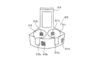
また、図5に示すように、第1試薬容器ラック310は、第1試薬テーブル11に5つ配置可能である。この5つの第1試薬容器ラック310に、試薬容器300が円環状に配置される。第1試薬容器ラック310は、図15および図17に示すように、試薬容器300を保持するための2つの保持部311および312と、保持部311および312の前面側にそれぞれ設けられた切欠部311aおよび312aと、上方に突出するように設けられた1つの把持部313とを含む。また、図15に示すように、保持部311および312は、平面的に見て円形状に形成されており、円筒形状の試薬容器300が差し込まれることにより試薬容器300を保持可能である。また、アダプタ(図示せず)を保持部311または312に取り付けることにより、上記保持部311または312の内径よりも小さい外径を有する試薬容器300を保持部311または312に保持させることが可能である。また、第1試薬容器ラック310は、保持部311および312の内径の組み合わせが異なるように形成された2種類のラックを含む。ユーザは、適宜ラックの種類を変えることによって、様々な大きさの試薬容器300に対応可能である。また、保持部311および312の外側面の前面側には、それぞれ、バーコード311bおよび312bが設けられており、保持部311および312の内側面には、それぞれ、バーコード311cおよび312cが設けられている。   Further, as shown in FIG. 5, five first reagent container racks 310 can be arranged on the first reagent table 11. The reagent containers 300 are annularly arranged in the five first reagent container racks 310. As shown in FIGS. 15 and 17, the first reagent container rack 310 includes two holding parts 311 and 312 for holding the reagent container 300, and a notch provided on the front side of the holding parts 311 and 312. 311a and 312a and one grip part 313 provided so as to protrude upward. As shown in FIG. 15, the holding portions 311 and 312 are formed in a circular shape when seen in a plan view, and the reagent container 300 can be held by inserting the cylindrical reagent container 300. Further, by attaching an adapter (not shown) to the holding unit 311 or 312, the reagent container 300 having an outer diameter smaller than the inner diameter of the holding unit 311 or 312 can be held by the holding unit 311 or 312. is there. The first reagent container rack 310 includes two types of racks formed so that combinations of inner diameters of the holding portions 311 and 312 are different. The user can cope with reagent containers 300 of various sizes by appropriately changing the type of rack. Further, barcodes 311b and 312b are provided on the front side of the outer surface of the holding portions 311 and 312 respectively, and barcodes 311c and 312c are provided on the inner side surfaces of the holding portions 311 and 312 respectively. ing.

2つの保持部311および312は、検体から測定用試料を調製する際に添加される種々の試薬を収容した複数の試薬容器300を1つずつ保持することが可能である。すなわち、第1試薬テーブル11には、最大10個(2×5=10)の試薬容器300が配置可能である。また、切欠部311aおよび312aは、それぞれ、バーコード311cおよび312cを試薬バーコードリーダ350(図5参照)によって読み取るために設けられている。また、把持部313は、第1試薬容器ラック310を試薬保存部6から取り出す時に把持される。   The two holding units 311 and 312 can hold a plurality of reagent containers 300 each containing various reagents added when preparing a measurement sample from a specimen. That is, a maximum of ten (2 × 5 = 10) reagent containers 300 can be arranged in the first reagent table 11. The notches 311a and 312a are provided to read the barcodes 311c and 312c with the reagent barcode reader 350 (see FIG. 5), respectively. In addition, the grip portion 313 is gripped when the first reagent container rack 310 is taken out from the reagent storage portion 6.

バーコード311bおよび312bには、それぞれ、保持部311および312の位置を識別するための位置情報(ホルダ番号)が含まれている。また、バーコード311cおよび312cには、保持部311および312に保持される試薬容器300は存在しないことを示す情報(試薬容器無し情報)が含まれている。また、試薬容器300のバーコード300aには、試薬容器300に収容されている試薬の詳細情報(試薬名、試薬容器の種類、ロット番号、試薬の有効期限などの情報)を特定するための情報が含まれている。   The bar codes 311b and 312b include position information (holder number) for identifying the positions of the holding units 311 and 312 respectively. The barcodes 311c and 312c include information (reagent absence information) indicating that the reagent container 300 held in the holding units 311 and 312 does not exist. In addition, the barcode 300a of the reagent container 300 includes information for specifying detailed information (information such as reagent name, reagent container type, lot number, and reagent expiration date) stored in the reagent container 300. It is included.

なお、たとえば、試薬容器300が保持部311に保持されている場合には、バーコード311cは読み取られず、試薬容器300のバーコード300aが読み取られる。すなわち、試薬バーコードリーダ350によってバーコード311bを読み取った後にバーコード300aを読み取った場合は、制御部4aは、バーコード300aによる試薬情報を有する試薬が保持部311に保持されていると認識するように構成されている。そして、試薬管理画面410の試薬配置表示領域420において、保持部311に対応する位置に第1試薬マーク421が表示されるように構成されている。また、試薬バーコードリーダ350によってバーコード311bを読み取った後にバーコード311cを読み取った場合は、制御部4aは、保持部311に保持されている試薬容器300は存在しないと認識するように構成されている。そして、試薬管理画面410の試薬配置表示領域420において、保持部311に対応する位置に試薬未配置マーク427が表示されるように構成されている。また、試薬バーコードリーダ350によってバーコード311bを読み取った後にバーコード300aまたはバーコード311cのいずれも読み取らなかった場合(試薬容器300が横を向いている場合など)には、制御部4aは、読み取りエラーを認識するとともに、表示部4bにおいて、読み取りが失敗したことを表すバーコード読取エラーマークEが表示されるように構成されている。また、第1試薬テーブル11に第1試薬容器ラック自体が配置されていない場合には、試薬バーコードリーダ350は、第1試薬容器ラック310のバーコード311b、312b、311c、312cおよび試薬容器300のバーコード300aを読み取ることがないように構成されている。このため、試薬管理画面410の試薬配置表示領域420において、第1試薬容器ラック310が配置されていない部分に対応する第1ラックマーク424上には、ラック未配置マーク426が表示されるように構成されている。   For example, when the reagent container 300 is held by the holding unit 311, the barcode 311 c is not read, and the barcode 300 a of the reagent container 300 is read. That is, when the barcode 300a is read after the barcode 311b is read by the reagent barcode reader 350, the control unit 4a recognizes that the reagent having the reagent information by the barcode 300a is held in the holding unit 311. It is configured as follows. In the reagent arrangement display area 420 of the reagent management screen 410, the first reagent mark 421 is displayed at a position corresponding to the holding unit 311. When the barcode 311c is read after the barcode 311b is read by the reagent barcode reader 350, the control unit 4a is configured to recognize that the reagent container 300 held in the holding unit 311 does not exist. ing. In the reagent arrangement display area 420 of the reagent management screen 410, a reagent non-arrangement mark 427 is displayed at a position corresponding to the holding unit 311. When neither the barcode 300a nor the barcode 311c is read after the barcode 311b is read by the reagent barcode reader 350 (for example, when the reagent container 300 faces sideways), the control unit 4a In addition to recognizing a reading error, a bar code reading error mark E indicating that reading has failed is displayed on the display unit 4b. Further, when the first reagent container rack itself is not arranged on the first reagent table 11, the reagent barcode reader 350 displays the barcodes 311 b, 312 b, 311 c, 312 c of the first reagent container rack 310 and the reagent container 300. The barcode 300a is not read. Therefore, in the reagent arrangement display area 420 of the reagent management screen 410, the rack non-placement mark 426 is displayed on the first rack mark 424 corresponding to the portion where the first reagent container rack 310 is not placed. It is configured.

また、第2試薬容器ラック320は、図5に示すように、第2試薬テーブル12に5つ配置可能である。この5つの試薬容器ラック320に、試薬容器300が円環状に配置される。また、互いに隣接する第2試薬容器ラック320の5箇所の隙間のうち、1個所は、他の4箇所の隙間の間隔よりも大きい間隔を有する。この大きい間隔を有する隙間12aを介して、試薬保存部6の外部に位置する試薬バーコードリーダ350により、第2試薬テーブル12の内側に位置する第1試薬テーブル11に配置される第1試薬容器ラック310のバーコード311bおよび312bと、第1試薬容器ラック310に保持される試薬容器300のバーコード300aとが読み取られる。また、第2試薬容器ラック320は、図16および図18に示すように、試薬容器300を保持するための6つの保持部321〜326と、保持部321〜326の前面側にそれぞれ設けられた切欠部321a〜326aと、上方に突出するように設けられた1つの把持部327とを含む。また、第2試薬容器ラック320の保持部321〜326は、第1試薬容器ラック310と同様に、平面的に見て円形状に形成されており、円筒形状の試薬容器300が差し込まれることにより試薬容器300を保持可能である。この第2試薬容器ラック320は、保持部321〜326の内径の組み合わせがそれぞれ異なるように形成された3種類のラックを含む。また、第2試薬容器ラック320には、第1試薬容器ラック310に配置された試薬と同じ試薬を配置することが可能に構成されている。   Further, five second reagent container racks 320 can be arranged on the second reagent table 12 as shown in FIG. In these five reagent container racks 320, the reagent containers 300 are arranged in an annular shape. In addition, one of the five gaps of the second reagent container rack 320 adjacent to each other has an interval larger than the interval between the other four gaps. The first reagent container disposed on the first reagent table 11 located inside the second reagent table 12 by the reagent barcode reader 350 located outside the reagent storage unit 6 through the gap 12a having a large interval. The barcodes 311b and 312b of the rack 310 and the barcode 300a of the reagent container 300 held in the first reagent container rack 310 are read. Further, as shown in FIGS. 16 and 18, the second reagent container rack 320 is provided on each of the six holding parts 321 to 326 for holding the reagent container 300 and the front side of the holding parts 321 to 326. It includes notches 321a to 326a and one grip 327 provided so as to protrude upward. Further, the holding portions 321 to 326 of the second reagent container rack 320 are formed in a circular shape when seen in a plan view, like the first reagent container rack 310, and the cylindrical reagent container 300 is inserted. The reagent container 300 can be held. The second reagent container rack 320 includes three types of racks formed so that the combinations of the inner diameters of the holding portions 321 to 326 are different from each other. Further, the second reagent container rack 320 is configured such that the same reagent as the reagent arranged in the first reagent container rack 310 can be arranged.

また、前列側の切欠部321aの両側には、バーコード321bと322bとが設けられている。また、同様に、切欠部323aの両側および切欠部325aの両側には、それぞれ、バーコード323bおよび324b、および、バーコード325bおよび326bが設けられている。また、保持部321〜326の内側面には、それぞれ、バーコード321c〜326cが設けられている。   Further, barcodes 321b and 322b are provided on both sides of the notch portion 321a on the front row side. Similarly, barcodes 323b and 324b and barcodes 325b and 326b are provided on both sides of the notch 323a and on both sides of the notch 325a, respectively. In addition, barcodes 321c to 326c are provided on the inner side surfaces of the holding portions 321 to 326, respectively.

このバーコード321b〜326bには、それぞれ、保持部321〜326の位置を識別するための位置情報(ホルダ番号)が含まれている。また、バーコード321cおよび326cには、保持部321〜326に保持される試薬容器300は存在しないことを示す情報(試薬容器無し情報)が含まれている。   The bar codes 321b to 326b include position information (holder numbers) for identifying the positions of the holding units 321 to 326, respectively. Further, the barcodes 321c and 326c include information (reagent absence information) indicating that the reagent container 300 held in the holding units 321 to 326 does not exist.

また、試薬バーコードリーダ350によって読み取られた試薬情報または試薬容器無し情報は、位置情報(ホルダ番号)と対応させて制御部4aのハードディスク401dの試薬情報データベース36に記憶されるように構成されている。また、ハードディスク401dの試薬情報データベース36に記憶された情報は、制御装置4の制御部4aにより表示部4bの試薬管理画面410に反映されるように構成されている。   The reagent information or the reagent container absence information read by the reagent barcode reader 350 is configured to be stored in the reagent information database 36 of the hard disk 401d of the control unit 4a in association with the position information (holder number). Yes. The information stored in the reagent information database 36 of the hard disc 401d is configured to be reflected on the reagent management screen 410 of the display unit 4b by the control unit 4a of the control device 4.

また、バーコード311b、312bおよび321b〜326bは、4桁の値を示している。1桁目は、「A」または「B」の値をとり、「A」は、試薬容器300が第2試薬テーブル12に配置されていることを示し、「B」は、試薬容器300が第1試薬テーブル11に配置されていることを示す。また、2桁目は、「1」〜「5」の値をとり、「1」〜「3」は、それぞれ、第2試薬容器ラック320の3種類の形状を示し、「4」および「5」は、それぞれ、第1試薬容器ラック310の2種類の形状を示す。また、3桁目は、「0」〜「9」の値をとり、第1試薬容器ラック310または第2試薬容器ラック320の番号を示す。また、4桁目は、第1試薬容器ラック310のバーコード311bおよび312bでは、「1」または「2」の値をとり、「1」および「2」は、それぞれ、保持部311および312を示す。また、第2試薬容器ラック320のバーコード321b〜326bでは、「1」〜「6」の値をとり、「1」〜「6」は、それぞれ、保持部321〜326を示す。このバーコード(バーコード311b、312bおよび321b〜326b)の値は、図9に示すように、試薬管理画面410の第1試薬マーク421の位置表示部421a、第2試薬マーク422の位置表示部422aまたは試薬未配置マーク427の位置表示部427aに反映されるように構成されている。たとえば、バーコードの値が「A11−6」であった場合には、第2試薬テーブル12に配置可能であるとともに、3種類の内の「1」に対応するラック(第2試薬容器ラック320)であり、ラック番号1の第2試薬容器ラック320の6番目の保持部(保持部326)を表す。すなわち、4桁の値のうち、前3桁は、試薬容器ラックを特定し、後1桁は、その試薬容器ラックにおける試薬の位置を特定する。   Bar codes 311b, 312b and 321b to 326b indicate four-digit values. The first digit takes a value of “A” or “B”, “A” indicates that the reagent container 300 is arranged in the second reagent table 12, and “B” indicates that the reagent container 300 is the first one. 1 indicates that it is arranged in the reagent table 11. The second digit takes a value of “1” to “5”, and “1” to “3” indicate the three types of shapes of the second reagent container rack 320, respectively, “4” and “5”. "Indicates two types of shapes of the first reagent container rack 310, respectively. The third digit takes a value of “0” to “9” and indicates the number of the first reagent container rack 310 or the second reagent container rack 320. The fourth digit takes a value of “1” or “2” in the barcodes 311b and 312b of the first reagent container rack 310, and “1” and “2” indicate the holding units 311 and 312 respectively. Show. Further, the barcodes 321b to 326b of the second reagent container rack 320 take values of “1” to “6”, and “1” to “6” indicate the holding units 321 to 326, respectively. As shown in FIG. 9, the values of the bar codes (bar codes 311b, 312b and 321b to 326b) are the position display section 421a of the first reagent mark 421 and the position display section of the second reagent mark 422 on the reagent management screen 410. 422a or the reagent non-placement mark 427 is configured to be reflected in the position display part 427a. For example, when the barcode value is “A11-6”, it can be placed in the second reagent table 12 and the rack corresponding to “1” of the three types (second reagent container rack 320). ) And represents the sixth holding part (holding part 326) of the second reagent container rack 320 of rack number 1. That is, among the four digits, the first three digits specify the reagent container rack, and the last one digit specifies the position of the reagent in the reagent vessel rack.

また、詳細情報のうちの試薬名は、試薬管理画面410の第1試薬マーク421および第2試薬マーク422の試薬名表示部421bおよび422bに反映されるように構成されている。また、試薬容器無し情報は、試薬未配置マーク427に反映されるように構成されている。すなわち、図9に示すように、試薬が配置されていた場合には、試薬名表示部421bまたは422bに試薬名が表示され、試薬が配置されていない場合には、試薬名表示部421bまたは422bには何も表示されない。たとえば、図9では、試薬位置「A12−5」には、試薬名「Streplok」が配置されており、試薬位置「A14−2」には、試薬が配置されていない。   The reagent name in the detailed information is configured to be reflected in the reagent name display portions 421b and 422b of the first reagent mark 421 and the second reagent mark 422 on the reagent management screen 410. The reagent container absence information is configured to be reflected in the reagent non-placement mark 427. That is, as shown in FIG. 9, when a reagent is arranged, the reagent name is displayed on the reagent name display part 421b or 422b. When no reagent is arranged, the reagent name display part 421b or 422b is displayed. Does not display anything. For example, in FIG. 9, the reagent name “Strrepok” is arranged at the reagent position “A12-5”, and no reagent is arranged at the reagent position “A14-2”.

また、試薬交換部7は、図1および図2に示すように、検体分析装置1の中央部近傍に設けられている。ここで、本実施形態では、試薬交換部7は、図3に示すように、ロック機構31および41をそれぞれ備えた取り外し可能な第1蓋部30および第2蓋部40と、ユーザに第1試薬テーブル11および第2試薬テーブル12の搬送状態を通知する通知部50とを含んでいる。   The reagent replacement unit 7 is provided in the vicinity of the center of the sample analyzer 1 as shown in FIGS. Here, in this embodiment, as shown in FIG. 3, the reagent replacement unit 7 includes a removable first lid 30 and second lid 40 each having a lock mechanism 31 and 41, and a first to the user. And a notification unit 50 for notifying the transport state of the reagent table 11 and the second reagent table 12.

第1蓋部30は、第1試薬テーブル11(第1試薬容器ラック310)に配置された試薬容器300の交換が行われる際に取り外すことが可能なように構成されている。また、第1蓋部30のロック機構31は、通常使用時、または、試薬の交換または追加が終了した後に、第1蓋部30が外れないようにロックするとともに、第1試薬テーブル11における試薬の交換または追加が終了したことを制御部4aに認識させるために設けられている。   The first lid 30 is configured to be removable when the reagent container 300 disposed on the first reagent table 11 (first reagent container rack 310) is exchanged. Further, the lock mechanism 31 of the first lid 30 locks the first lid 30 so that it does not come off during normal use or after the replacement or addition of the reagent is completed, and the reagent in the first reagent table 11. It is provided in order for the control unit 4a to recognize that the replacement or addition has been completed.

また、第2蓋部40は、第2試薬テーブル12(第2試薬容器ラック320)に配置された試薬容器300の交換の際に取り外すことが可能なように構成されている。また、第2蓋部40のロック機構41は、通常使用時、または、試薬の交換が終了した後に、第2蓋部40が外れないようにロックするとともに、第2試薬テーブル12における試薬の交換または追加が終了したことを制御部4aに認識させるために設けられている。   The second lid 40 is configured to be removable when replacing the reagent container 300 disposed on the second reagent table 12 (second reagent container rack 320). Further, the lock mechanism 41 of the second lid 40 locks the second lid 40 so that it does not come off during normal use or after the reagent replacement is completed, and also replaces the reagent in the second reagent table 12. Alternatively, it is provided to make the control unit 4a recognize that the addition has been completed.

また、通知部50は、2つのLEDインジケータ51および52を含む。図1および図3に示すように、2つのLEDインジケータ51および52は、第2蓋部40の近傍に配置されており、検体分析装置1の外部からユーザが視認可能である。また、LEDインジケータ51および52は、青色または赤色に発光可能である。   The notification unit 50 includes two LED indicators 51 and 52. As shown in FIGS. 1 and 3, the two LED indicators 51 and 52 are disposed in the vicinity of the second lid portion 40, and are visible to the user from the outside of the sample analyzer 1. The LED indicators 51 and 52 can emit blue or red light.

LEDインジケータ51は、ユーザが試薬管理画面410において指定した第1試薬テーブル11の試薬に対応する第1試薬容器ラック310が、試薬の交換が可能な取出位置(第1蓋部30の下方)に移動されたことをユーザに通知する機能を有する。具体的には、第1試薬テーブル11が回転移動中には、LEDインジケータ51は、赤色に発光し、指定された第1試薬テーブル11の試薬に対応する第1試薬容器ラック310が取出位置に移動されて停止した時には、青色に発光するように構成されている。これにより、ユーザに、試薬の交換または追加のために第1蓋部30を取り外すタイミングを通知することが可能である。   The LED indicator 51 is positioned at the take-out position (below the first lid 30) where the first reagent container rack 310 corresponding to the reagent in the first reagent table 11 specified by the user on the reagent management screen 410 can be replaced. It has a function of notifying the user that it has been moved. Specifically, while the first reagent table 11 is rotating, the LED indicator 51 emits red light, and the first reagent container rack 310 corresponding to the reagent of the designated first reagent table 11 is at the take-out position. When it is moved and stopped, it is configured to emit blue light. Thereby, it is possible to notify a user of the timing which removes the 1st cover part 30 for replacement | exchange or addition of a reagent.

また、LEDインジケータ52は、ユーザが試薬管理画面410において指定した第2試薬テーブル12の試薬に対応する第2試薬容器ラック320が、試薬の交換が可能な取出位置(第2蓋部40の下方)に移動されたことをユーザに通知する機能を有する。LEDインジケータ52は、LEDインジケータ51と同様に、第2試薬テーブル12が回転移動中には赤色に発光し、指定された第2試薬テーブル12の試薬に対応する第2試薬容器ラック320が取出位置に移動されて停止した時には、青色に発光するように構成されている。   In addition, the LED indicator 52 has an extraction position (below the second lid 40) at which the second reagent container rack 320 corresponding to the reagent in the second reagent table 12 specified by the user on the reagent management screen 410 can be replaced. ) To notify the user that it has been moved. Similarly to the LED indicator 51, the LED indicator 52 emits red light while the second reagent table 12 is rotationally moved, and the second reagent container rack 320 corresponding to the reagent of the designated second reagent table 12 is in the take-out position. It is configured to emit blue light when it is moved to stop.

また、試薬の交換または追加が終了した後、第1蓋部30または第2蓋部40のロックがユーザにより行われると、検体分析装置1は、自動的に、交換された試薬が保持される第1試薬容器ラック310または第2試薬容器ラック320に保持される全ての試薬容器300のバーコード300aの読み取りが行われるように構成されている。これにより、たとえば、1つの試薬を指定して試薬の交換を指示した際に、指定した試薬に加えて、同じ第1試薬容器ラック310または第2試薬容器ラック320に含まれる指定した試薬以外の試薬も交換した場合にも、交換後の試薬の配置が正しく試薬管理画面410に反映される。   Further, after the replacement or addition of the reagent is completed, when the user locks the first lid 30 or the second lid 40, the sample analyzer 1 automatically holds the replaced reagent. The barcode 300a of all the reagent containers 300 held in the first reagent container rack 310 or the second reagent container rack 320 is read. Thus, for example, when one reagent is designated and a reagent replacement is instructed, in addition to the designated reagent, other than the designated reagent contained in the same first reagent container rack 310 or second reagent container rack 320 Even when the reagent is exchanged, the arrangement of the reagent after the exchange is correctly reflected on the reagent management screen 410.

また、測定機構部2は、さらに、図3〜図5に示すように、キュベット搬送部60と、検体分注アーム70と、第1光学的情報取得部80と、ランプユニット90と、加温部100と、キュベット移送部110と、試薬分注アーム120と、第2光学的情報取得部130と、緊急検体セット部140と、流体部150と、キュベット供給機構部160とを備えている。   The measurement mechanism unit 2 further includes a cuvette transport unit 60, a sample dispensing arm 70, a first optical information acquisition unit 80, a lamp unit 90, a heating unit, as shown in FIGS. Unit 100, cuvette transfer unit 110, reagent dispensing arm 120, second optical information acquisition unit 130, emergency sample setting unit 140, fluid unit 150, and cuvette supply mechanism unit 160.

キュベット搬送部60は、キュベット200を検体分析装置1の各部分に搬送する機能を有する。キュベット搬送部60は、円環形状の第2試薬テーブル12の外側に配置された円環形状のキュベット搬送テーブル61と、キュベット搬送テーブル61上に円周方向に沿って所定の間隔を隔てて設けられた円筒形状の複数のキュベット保持部62とからなる。キュベット保持部62は、キュベット200を1つずつ保持するために設けられている。キュベット搬送テーブル61のキュベット保持部62に保持されたキュベット200(図5参照)には、搬送機構部3の試験管250に収容されている検体および試薬保存部6に保存されている試薬が分注され、測定用試料が調製される。   The cuvette transport unit 60 has a function of transporting the cuvette 200 to each part of the sample analyzer 1. The cuvette transport unit 60 is provided on the cuvette transport table 61 at a predetermined interval along the circumferential direction, and an annular cuvette transport table 61 disposed outside the annular second reagent table 12. And a plurality of cylindrical cuvette holders 62. The cuvette holder 62 is provided to hold the cuvettes 200 one by one. In the cuvette 200 (see FIG. 5) held in the cuvette holding unit 62 of the cuvette transfer table 61, the sample stored in the test tube 250 of the transfer mechanism unit 3 and the reagent stored in the reagent storage unit 6 are distributed. A sample for measurement is prepared.

検体分注アーム70は、搬送機構部3により吸引位置2aに搬送された試験管250に収容される検体を吸引するとともに、吸引した検体をキュベット搬送テーブル61のキュベット保持部62に保持されたキュベット200内に分注する機能を有している。検体分注アーム70は、分注動作を行う際に、ステッピングモータ(図示せず)によるパルス制御によりピペット部71(図4参照)を上下方向に移動させるように構成されている。また、検体分注アーム70のピペット部71の先端には、液面を検知するためのセンサ(図示せず)が設けられている。これにより、試薬の液面を検知するまでのパルス数と1パルス分の移動量とによって試薬容器300における試薬の液面の高さを算出することが可能である。本実施形態では、試薬残量確認ボタン440dが押下されて残量の確認が指示された場合には、試薬分注アーム120だけでなく検体分注アーム70も用いて試薬の残量を検出するように構成されている。   The sample dispensing arm 70 aspirates the sample accommodated in the test tube 250 conveyed to the aspiration position 2 a by the conveyance mechanism unit 3 and also holds the aspirated sample in the cuvette holding unit 62 of the cuvette conveyance table 61. 200 has a function of dispensing. The sample dispensing arm 70 is configured to move the pipette unit 71 (see FIG. 4) in the vertical direction by pulse control by a stepping motor (not shown) when performing a dispensing operation. A sensor (not shown) for detecting the liquid level is provided at the tip of the pipette unit 71 of the sample dispensing arm 70. Thereby, the height of the reagent liquid level in the reagent container 300 can be calculated from the number of pulses until the reagent liquid level is detected and the amount of movement for one pulse. In the present embodiment, when the reagent remaining amount confirmation button 440d is pressed and confirmation of the remaining amount is instructed, the remaining amount of the reagent is detected using not only the reagent dispensing arm 120 but also the sample dispensing arm 70. It is configured as follows.

第1光学的情報取得部80は、試薬を添加する前の検体中の干渉物質(乳び、ヘモグロビンおよびビリルビン)の有無およびその濃度を測定するために、検体から光学的な情報を取得するように構成されている。具体的には、後述するランプユニット90から照射される5種類の光(340nm、405nm、575nm、660nmおよび800nm)の内の4種類の光(405nm、575nm、660nmおよび800nm)を用いて、干渉物質の有無およびその濃度を測定している。なお、405nmの波長を有する光は、乳び、ヘモグロビンおよびビリルビンのいずれにも吸収される光である。すなわち、405nmの波長を有する光により測定された光学的な情報には、乳び、ヘモグロビンおよびビリルビンの影響が寄与している。また、575nmの波長を有する光は、ビリルビンには実質的に吸収されず、かつ、乳びおよびヘモグロビンに吸収される光である。すなわち、575nmの波長を有する光により測定された光学的な情報には、乳びおよびヘモグロビンの影響が寄与している。そして、660nmおよび800nmの波長を有する光は、ビリルビンおよびヘモグロビンには実質的に吸収されず、かつ、乳びに吸収される光である。すなわち、660nmおよび800nmの波長を有する光により測定された光学的な情報には、乳びの影響が寄与している。また、乳びは、底波長域の405nmから高波長域の800nmまでの波長の光を吸収しており、660nmの波長を有する光の方が、800nmの波長を有する光に比べて、乳びによる吸収が多い。すなわち、800nmの波長を有する光で測定した光学的な情報の方が、660nmの波長を有する光で測定した光学的な情報より、乳びの影響が小さい。   The first optical information acquisition unit 80 acquires optical information from the specimen in order to measure the presence and concentration of interfering substances (chyle, hemoglobin, and bilirubin) in the specimen before adding the reagent. It is configured. Specifically, interference is performed using four types of light (405 nm, 575 nm, 660 nm, and 800 nm) among five types of light (340 nm, 405 nm, 575 nm, 660 nm, and 800 nm) emitted from the lamp unit 90 described later. The presence of substance and its concentration are measured. In addition, the light which has a wavelength of 405 nm is light absorbed by all of chyle, hemoglobin, and bilirubin. That is, the influence of chyle, hemoglobin, and bilirubin contributes to optical information measured by light having a wavelength of 405 nm. In addition, light having a wavelength of 575 nm is light that is not substantially absorbed by bilirubin and absorbed by chyle and hemoglobin. That is, the influence of chyle and hemoglobin contributes to optical information measured by light having a wavelength of 575 nm. And the light which has a wavelength of 660 nm and 800 nm is light which is not substantially absorbed by bilirubin and hemoglobin but is absorbed by chyle. That is, the influence of chyle contributes to optical information measured by light having wavelengths of 660 nm and 800 nm. In addition, chyle absorbs light having a wavelength from 405 nm in the bottom wavelength region to 800 nm in the high wavelength region, and light having a wavelength of 660 nm is more chyle than light having a wavelength of 800 nm. Absorption due to That is, optical information measured with light having a wavelength of 800 nm is less affected by chyle than optical information measured with light having a wavelength of 660 nm.

この第1光学的情報取得部80による検体の光学的な情報の取得は、第2光学的情報取得部130による検体の光学的な測定(本測定)の前に行われる。第1光学的情報取得部80は、キュベット搬送テーブル61のキュベット保持部62に保持されたキュベット200内の検体から光学的な情報(検体の透過光による情報)を取得する。   The acquisition of the optical information of the specimen by the first optical information acquisition unit 80 is performed before the optical measurement (main measurement) of the specimen by the second optical information acquisition unit 130. The first optical information acquisition unit 80 acquires optical information (information by the transmitted light of the sample) from the sample in the cuvette 200 held by the cuvette holding unit 62 of the cuvette transport table 61.

また、第1光学的情報取得部80は、制御装置4の制御部4aに電気的に接続されており、第1光学的情報取得部80において取得されたデータ(光学的な情報)を制御装置4の制御部4aに送信する。これにより、制御装置4において、第1光学的情報取得部80からのデータの分析(解析)が行われることにより、分岐光ファイバ91から出射される5種類の光に対するキュベット200内の検体の吸光度が求められるとともに、検体中の干渉物質の有無やその濃度などが分析される。そして、本実施形態では、検体中の干渉物質の有無やその濃度などに基づいて、後述する第2光学的情報取得部130で測定した光学的な情報を分析するか否かが判断される。   Further, the first optical information acquisition unit 80 is electrically connected to the control unit 4a of the control device 4, and the data (optical information) acquired by the first optical information acquisition unit 80 is controlled by the control device. 4 to the control unit 4a. As a result, the control device 4 analyzes (analyzes) the data from the first optical information acquisition unit 80, and thereby the absorbance of the specimen in the cuvette 200 with respect to the five types of light emitted from the branch optical fiber 91. And the presence / absence of the interfering substance in the sample and its concentration are analyzed. In this embodiment, it is determined whether or not to analyze the optical information measured by the second optical information acquisition unit 130 described later, based on the presence or absence of the interfering substance in the sample and its concentration.

ランプユニット90は、図5に示すように、第1光学的情報取得部80および第2光学的情報取得部130で行われる光学的な測定に用いられる5種類の波長を有する光(340nm、405nm、575nm、660nmおよび800nm)を供給するために設けられている。すなわち、1つのランプユニット90が、第1光学的情報取得部80および第2光学的情報取得部130に対して共通に用いられるように構成されている。また、ランプユニット90の光は、分岐光ファイバ91および分岐光ファイバ92によって、それぞれ、第1光学的情報取得部80および第2光学的情報取得部130に供給される。   As shown in FIG. 5, the lamp unit 90 includes light (340 nm and 405 nm) having five types of wavelengths used for optical measurement performed by the first optical information acquisition unit 80 and the second optical information acquisition unit 130. 575 nm, 660 nm and 800 nm). That is, one lamp unit 90 is configured to be used in common for the first optical information acquisition unit 80 and the second optical information acquisition unit 130. The light from the lamp unit 90 is supplied to the first optical information acquisition unit 80 and the second optical information acquisition unit 130 through the branch optical fiber 91 and the branch optical fiber 92, respectively.

加温部100は、保温可能なプレート101からなり、10個の凹形状のキュベット保持部101aが設けられている。各キュベット保持部101aは、それぞれ、1つのキュベット200を保持可能であり、検体が分注されたキュベット200をキュベット保持部101aに数分間保持することによって、キュベット200内の検体を約37℃に加温する機能を有する。また、加温部100で加温された検体は、加温が終了してから一定時間内に試薬の分注および測定が行われる。これにより、検体、および、検体と試薬とから調製される測定試料の変質を抑制するとともに、測定結果を安定させることが可能である。   The heating unit 100 includes a plate 101 capable of maintaining heat, and is provided with ten concave cuvette holding units 101a. Each cuvette holding unit 101a can hold one cuvette 200. By holding the cuvette 200 into which the sample is dispensed in the cuvette holding unit 101a for several minutes, the sample in the cuvette 200 is brought to about 37 ° C. Has the function of heating. The sample heated by the heating unit 100 is dispensed and measured with a reagent within a predetermined time after the heating is completed. Thereby, it is possible to suppress the deterioration of the sample and the measurement sample prepared from the sample and the reagent, and to stabilize the measurement result.

また、キュベット移送部110は、キュベット200を、キュベット搬送部60と、保温部110と、第2光学的情報取得部130との間を移送させるために設けられている。キュベット移送部110は、キュベット200を把持する移送用キャッチャ部111と、移送用キャッチャ部111を移動させるための駆動部112とを含む。移送用キャッチャ部111は、駆動部112の駆動により移動領域110a内を移動可能であり、キュベット搬送部60と、加温部100と、第2光学的情報取得部130の測定用載置部131との間でキュベット200の移送を行う。また、移送用キャッチャ部111には振動機能が設けられており、キュベット200を把持した状態でキュベット200を振動させることにより、キュベット200内の検体と試薬とを攪拌することが可能である。   The cuvette transfer unit 110 is provided to transfer the cuvette 200 between the cuvette transport unit 60, the heat retaining unit 110, and the second optical information acquisition unit 130. The cuvette transfer unit 110 includes a transfer catcher unit 111 that holds the cuvette 200, and a drive unit 112 that moves the transfer catcher unit 111. The transfer catcher 111 can move in the moving area 110 a by driving the drive unit 112, and the cuvette transport unit 60, the heating unit 100, and the measurement mounting unit 131 of the second optical information acquisition unit 130. The cuvette 200 is transferred between the two. The transfer catcher 111 is provided with a vibration function, and the sample and the reagent in the cuvette 200 can be agitated by vibrating the cuvette 200 while holding the cuvette 200.

試薬分注アーム120は、図3〜図5に示すように、試薬保存部6に載置された試薬容器300内の試薬をキュベット200に分注することにより、キュベット200内の検体に試薬を混合するために設けられている。具体的には、前述した試薬保存部6の外壁部20の穴部22a、22bまたは22c(図3参照)を介して試薬の吸引を行い、加温(37℃)が完了したキュベット200を移送用キャッチャ部111が加温部100のキュベット保持部101aから取り出し、把持した状態で、吸引した試薬をキュベット200に分注する。なお、試薬分注アーム120のピペット部121には加温機能が設けられており、吸引された試薬は、瞬間的に約37℃に加温される。すなわち、試薬保存部6で低温(約10℃)保存されている試薬は、試薬分注アーム120によって約37℃に加温された状態で、加温が完了した約37℃の検体と混合される。このように、第1光学的情報取得部80による光学的な測定が終了した検体に試薬を添加して測定用試料が調製される。   As shown in FIGS. 3 to 5, the reagent dispensing arm 120 dispenses the reagent in the cuvette 200 by dispensing the reagent in the reagent container 300 placed on the reagent storage unit 6 to the cuvette 200. Provided for mixing. Specifically, the reagent is aspirated through the holes 22a, 22b or 22c (see FIG. 3) of the outer wall 20 of the reagent storage 6 described above, and the cuvette 200 that has been heated (37 ° C.) is transferred. The catcher unit 111 is taken out from the cuvette holding unit 101a of the heating unit 100 and dispensed into the cuvette 200 in the gripped state. The pipetting part 121 of the reagent dispensing arm 120 is provided with a heating function, and the aspirated reagent is instantaneously heated to about 37 ° C. That is, the reagent stored in the reagent storage unit 6 at a low temperature (about 10 ° C.) is mixed with the sample at about 37 ° C. where the heating is completed while being heated to about 37 ° C. by the reagent dispensing arm 120. The In this way, a sample for measurement is prepared by adding a reagent to the specimen for which optical measurement by the first optical information acquisition unit 80 has been completed.

試薬分注アーム120は、分注動作を行う際に、ステッピングモータ(図示せず)によるパルス制御によりピペット部121を上下方向に移動させるように構成されている。また、試薬分注アーム120のピペット部121の先端には、試薬容器300から試薬を吸引する際に、試薬の液面を検知するためのセンサ(図示せず)が設けられている。これにより、試薬の液面を検知するまでのパルス数と1パルス分の移動量とによって試薬容器300における試薬の液面の高さを算出することが可能である。試薬の液面の高さの算出手順については、後に詳細に説明する。   The reagent dispensing arm 120 is configured to move the pipette unit 121 in the vertical direction by pulse control by a stepping motor (not shown) when performing a dispensing operation. Further, a sensor (not shown) for detecting the liquid level of the reagent when the reagent is aspirated from the reagent container 300 is provided at the tip of the pipette unit 121 of the reagent dispensing arm 120. Thereby, the height of the reagent liquid level in the reagent container 300 can be calculated from the number of pulses until the reagent liquid level is detected and the amount of movement for one pulse. The procedure for calculating the height of the reagent surface will be described in detail later.

第2光学的情報取得部130は、測定用試料から光学的な情報を測定するための機能を有している。この第2光学的情報取得部130は、図5に示すように、測定用載置部131と、測定用載置部131の下方に配置された検出部132とにより構成されている。   The second optical information acquisition unit 130 has a function for measuring optical information from the measurement sample. As shown in FIG. 5, the second optical information acquisition unit 130 includes a measurement placement unit 131 and a detection unit 132 disposed below the measurement placement unit 131.

また、第2光学的情報取得部130の検出部132は、キュベット200内の測定用試料に対して複数の条件下で光学的な測定(本測定)を行うことが可能なように構成されている。また、第2光学的情報取得部130は、制御装置4の制御部4aに電気的に接続されており、取得したデータ(光学的な情報)を制御装置4の制御部4aに送信する。これにより、制御装置4において、予め取得済みの第1光学的情報取得部80からのデータ(光学的な情報)の分析結果に基づいて、第2光学的情報取得部130から送信されたデータ(光学的な情報)が分析されて、表示部4bに表示される。   The detection unit 132 of the second optical information acquisition unit 130 is configured to be able to perform optical measurement (main measurement) on a measurement sample in the cuvette 200 under a plurality of conditions. Yes. The second optical information acquisition unit 130 is electrically connected to the control unit 4 a of the control device 4 and transmits the acquired data (optical information) to the control unit 4 a of the control device 4. Thereby, in the control apparatus 4, based on the analysis result of the data (optical information) from the first optical information acquisition unit 80 that has been acquired in advance, the data transmitted from the second optical information acquisition unit 130 ( Optical information) is analyzed and displayed on the display unit 4b.

なお、分岐光ファイバ92から照射される660nmの波長を有する光は、Fbg(フィブリノーゲン量)、PT(プロトロンビン時間)およびAPTT(活性化部分トロンボプラスチン時間)を測定する際に用いられるメイン波長である。また、800nmの波長を有する光は、Fbg、PTおよびAPTTを測定する際に用いられるサブ波長である。合成基質法の測定項目であるATIIIの測定波長は405nmであり、免疫比濁法の測定項目であるDダイマーおよびFDPの測定波長は800nmである。また、血小板凝集の測定波長は、575nmである。   The light having a wavelength of 660 nm irradiated from the branch optical fiber 92 is a main wavelength used when measuring Fbg (fibrinogen amount), PT (prothrombin time), and APTT (activated partial thromboplastin time). Further, light having a wavelength of 800 nm is a sub-wavelength used when measuring Fbg, PT, and APTT. The measurement wavelength of ATIII which is a measurement item of the synthetic substrate method is 405 nm, and the measurement wavelength of D dimer and FDP which are measurement items of the immunoturbidimetric method is 800 nm. The measurement wavelength of platelet aggregation is 575 nm.

緊急検体セット部140は、図3〜図5に示すように、緊急を要する検体に対しての検体分析処理を行うために設けられている。この緊急検体セット部140は、搬送機構部3から供給された検体に対しての検体分析処理が行われている際に、緊急検体を割り込ませることが可能なように構成されている。また、緊急検体セット部140は、X方向にスライド可能であり、希釈液および洗浄液が収容された容器(図示せず)を保持するための5つの保持部141が設けられている。また、希釈液および洗浄液が収容された容器(図示せず)には、バーコード(図示せず)が貼付されている。希釈液および洗浄液のバーコードは、緊急検体セット部140がX方向にスライドされながら、バーコードリーダ351によって読み取られるように構成されている。これにより、希釈液および洗浄液の種類、配置などが試薬管理画面410の希釈・洗浄液マーク423として表示されるように構成されている。また、図1および図2に示すように、検体分析装置1の交換部7の前面側には、蓋部1cが設けられている。この蓋部1cを介して、希釈液および洗浄液が収容された容器(図示せず)の交換または追加が行われる。   As shown in FIGS. 3 to 5, the emergency sample setting unit 140 is provided for performing a sample analysis process on a sample that requires an emergency. The emergency sample setting unit 140 is configured to be able to interrupt an emergency sample when a sample analysis process is performed on the sample supplied from the transport mechanism unit 3. Further, the emergency specimen setting unit 140 is slidable in the X direction, and is provided with five holding units 141 for holding a container (not shown) in which a diluent and a cleaning solution are stored. Further, a barcode (not shown) is affixed to a container (not shown) in which a diluent and a cleaning solution are stored. The barcodes of the diluted solution and the cleaning solution are configured to be read by the barcode reader 351 while the emergency sample setting unit 140 is slid in the X direction. Accordingly, the type and arrangement of the diluted solution and the cleaning solution are displayed as the diluted / cleaning solution mark 423 on the reagent management screen 410. As shown in FIGS. 1 and 2, a lid 1 c is provided on the front side of the exchange unit 7 of the sample analyzer 1. Through this lid portion 1c, a container (not shown) containing a diluent and a cleaning solution is exchanged or added.

また、流体部150は、検体分析装置1のシャットダウン処理の際に、各分注アーム(検体分注アーム70および試薬分注アーム120)に設けられるノズルに洗浄液などの液体を供給するために設けられている。   The fluid unit 150 is provided to supply a liquid such as a cleaning liquid to the nozzles provided in each dispensing arm (the sample dispensing arm 70 and the reagent dispensing arm 120) during the shutdown process of the sample analyzer 1. It has been.

また、キュベット供給機構部160は、ユーザによって無造作に投入された複数のキュベット200をキュベット搬送部60に順次供給することが可能なように構成されている。このキュベット供給機構部160は、図3〜図5に示すように、第1ホッパ161aと、第1ホッパ161aからキュベット200が供給されるとともに、第1ホッパ161aよりも小さい第2ホッパ161bと、第2ホッパ161bからキュベット200が供給される2つの誘導板162と、2つの誘導板162の下端に配置された支持台163と、支持台163から所定の間隔を隔てて設けられた供給用キャッチャ部164とを含んでいる。第1ホッパ161a内に供給されたキュベット200は、第1ホッパ161aよりも小さい第2ホッパ161bを介して、誘導板162上を、支持台163に向かって滑り落ちながら移動するように構成されている。また、支持台163は、誘導板162を滑り落ちて移動したキュベット200を、供給用キャッチャ部164が把持可能な位置まで回転移送する機能を有している。そして、供給用キャッチャ部164は、支持台163により回転移送されたキュベット200をキュベット搬送部60に供給するために設けられている。   In addition, the cuvette supply mechanism unit 160 is configured to be able to sequentially supply a plurality of cuvettes 200 that are randomly inserted by the user to the cuvette transport unit 60. As shown in FIGS. 3 to 5, the cuvette supply mechanism 160 includes a first hopper 161 a, a cuvette 200 supplied from the first hopper 161 a, a second hopper 161 b smaller than the first hopper 161 a, Two guide plates 162 to which the cuvette 200 is supplied from the second hopper 161b, a support base 163 disposed at the lower ends of the two guide plates 162, and a supply catcher provided at a predetermined interval from the support base 163 Part 164. The cuvette 200 supplied into the first hopper 161a is configured to move while sliding down on the guide plate 162 toward the support base 163 via the second hopper 161b smaller than the first hopper 161a. Yes. Further, the support base 163 has a function of rotating and transferring the cuvette 200 that has been moved by sliding down the guide plate 162 to a position where the supply catcher unit 164 can grip it. The supply catcher unit 164 is provided to supply the cuvette 200 rotated and transferred by the support base 163 to the cuvette transport unit 60.

また、図3〜図5に示すように、測定機構部2には、上述した供給用キャッチャ部164から所定の間隔を隔てて、キュベット200を廃棄するための廃棄用孔171(図3および図5参照)と、廃棄用孔171の下方に設置された廃棄ボックス172とが設けられている。上述した供給用キャッチャ部164は、キュベット搬送部60のキュベット搬送テーブル61上のキュベット200を、廃棄用孔171(図3および図5参照)を介して廃棄ボックス172に廃棄することが可能である。すなわち、供給用キャッチャ部164は、キュベット200の供給と廃棄との両方を行うことが可能である。   Further, as shown in FIGS. 3 to 5, the measuring mechanism unit 2 has a disposal hole 171 (FIG. 3 and FIG. 3) for discarding the cuvette 200 at a predetermined interval from the supply catcher unit 164 described above. 5) and a disposal box 172 installed below the disposal hole 171. The supply catcher unit 164 described above can discard the cuvette 200 on the cuvette transport table 61 of the cuvette transport unit 60 into the discard box 172 through the discard hole 171 (see FIGS. 3 and 5). . That is, the supply catcher unit 164 can both supply and discard the cuvette 200.

次に、図4および図5を参照して、検体分析装置1の検体の分析動作について詳細に説明する。なお、ここでは、凝固時間法を用いた測定における動作について説明する。   Next, the sample analysis operation of the sample analyzer 1 will be described in detail with reference to FIGS. Here, the operation in the measurement using the coagulation time method will be described.

まず、図4に示した検体分析装置1の測定機構部2および制御装置4の電源をそれぞれオン状態にすることにより、検体分析装置1の初期設定が行われる。これにより、キュベット200を移動させるための機構と各分注アーム(検体分注アーム70および試薬分注アーム120)とを初期位置に戻すための動作や、制御装置4の制御部4aに記憶されているソフトウェアの初期化などが行われる。   First, the sample analyzer 1 is initially set by turning on the power of the measurement mechanism unit 2 and the control device 4 of the sample analyzer 1 shown in FIG. As a result, the mechanism for moving the cuvette 200 and each dispensing arm (specimen dispensing arm 70 and reagent dispensing arm 120) are returned to the initial position and stored in the control unit 4a of the control device 4. The software is initialized.

そして、図5に示した搬送機構部3によって、検体を収容した試験管250が載置されたラック251の搬送が行われる。これにより、ラックセット領域3aのラック251が測定機構部2の吸引位置2aに対応する位置まで搬送される。   The transport mechanism 3 shown in FIG. 5 transports the rack 251 on which the test tube 250 containing the sample is placed. Thereby, the rack 251 in the rack setting area 3a is transported to a position corresponding to the suction position 2a of the measurement mechanism unit 2.

そして、検体分注アーム70により試験管250から所定量の検体の吸引が行われる。そして、検体分注アーム70をキュベット搬送部60のキュベット搬送テーブル61に保持されたキュベット200の上方に移動させる。その後、検体分注アーム70からキュベット搬送テーブル61のキュベット200内に検体が吐出されることにより、キュベット200内に検体が分取される。   Then, a predetermined amount of sample is aspirated from the test tube 250 by the sample dispensing arm 70. Then, the specimen dispensing arm 70 is moved above the cuvette 200 held by the cuvette transport table 61 of the cuvette transport unit 60. Thereafter, the sample is dispensed into the cuvette 200 by discharging the sample from the sample dispensing arm 70 into the cuvette 200 of the cuvette transport table 61.

そして、キュベット搬送テーブル61を回転させて、検体が分注されたキュベット200を第1光学的情報取得部80による測定が可能な位置に搬送する。これにより、第1光学的情報取得部80による検体に対する光学的な測定が行われて、検体から光学的な情報が取得される。具体的には、キュベット搬送テーブル61のキュベット保持部62(図5参照)に保持されたキュベット200内の検体を透過した5種類(340nm、405nm、575nm、660nmおよび800nm)の光による電気信号のデータを制御装置4の制御部4aに送信する。これにより、第1光学的情報取得部80による検体に対する光学的な情報(第1光学的情報)の取得が完了する。   Then, the cuvette transport table 61 is rotated to transport the cuvette 200 into which the sample has been dispensed to a position where measurement by the first optical information acquisition unit 80 is possible. Thereby, the optical measurement with respect to the sample is performed by the first optical information acquisition unit 80, and optical information is acquired from the sample. Specifically, electric signals of five types (340 nm, 405 nm, 575 nm, 660 nm, and 800 nm) transmitted through the specimen in the cuvette 200 held by the cuvette holding unit 62 (see FIG. 5) of the cuvette transport table 61 are transmitted. Data is transmitted to the control unit 4a of the control device 4. Thereby, the acquisition of the optical information (first optical information) for the specimen by the first optical information acquisition unit 80 is completed.

そして、制御装置4の制御部4aは、受信したデータ(第1光学的情報)を用いて、検体の吸光度を算出するとともに、検体中の干渉物質(乳び、ヘモグロビン、ビリルビン)の有無およびその濃度を算出する。具体的には、ランプユニット90から照射される4種類(405nm、575nm、660nmおよび800nm)の光を用いて取得された光学的な情報(第1光学的情報)に基づいて、制御装置4の制御部4aは、検体の吸光度を算出し、この吸光度をRAM401cに記憶する。   Then, the control unit 4a of the control device 4 uses the received data (first optical information) to calculate the absorbance of the sample, and the presence / absence of an interfering substance (chyle, hemoglobin, bilirubin) in the sample. Calculate the concentration. Specifically, based on optical information (first optical information) acquired using four types of light (405 nm, 575 nm, 660 nm, and 800 nm) emitted from the lamp unit 90, The control unit 4a calculates the absorbance of the sample, and stores this absorbance in the RAM 401c.

その後、RAM401cに記憶されている吸光度のうち、メイン波長での吸光度が閾値以下か否かが判断される。具体的には、検体の検査項目が「PT」、「APTT」、「Fbg」等の凝固時間法の検査項目の場合には、これらの項目のメイン波長である660nmを有する光を照射して測定された第1光学的情報から算出した吸光度が閾値(たとえば、2.0)以下か否かが判断される。   Thereafter, it is determined whether or not the absorbance at the main wavelength among the absorbances stored in the RAM 401c is equal to or less than a threshold value. Specifically, when the test item of the specimen is a test item of the coagulation time method such as “PT”, “APTT”, “Fbg”, etc., light having 660 nm which is the main wavelength of these items is irradiated. It is determined whether or not the absorbance calculated from the measured first optical information is a threshold value (for example, 2.0) or less.

そして、第1光学的情報取得部80で測定された第1光学的情報から算出したメイン波長での吸光度が閾値以下の場合には、キュベット200は、キュベット移送部110により、キュベット搬送テーブル61から加温部100に移送される。そして、加温部100において約37℃になった検体を収容したキュベット200は、キュベット移送部110の移送用キャッチャ部111によって把持される。そして、移送用キャッチャ部111によってキュベット200が把持された状態で、試薬分注アーム120を駆動させて、試薬テーブル(第1試薬テーブル11または第2試薬テーブル12)に載置された試薬容器300内の試薬をキュベット200内の検体に添加する。この状態で、移送用キャッチャ部111の振動機能により、キュベット200内の検体および試薬が攪拌される。これにより、測定用試料の調製が行われる。そして、そのまま、キュベット移送部110により、測定用試料が収容されたキュベット200を第2光学的情報取得部130の測定用載置部131に移動させる。   When the absorbance at the main wavelength calculated from the first optical information measured by the first optical information acquisition unit 80 is equal to or less than the threshold value, the cuvette 200 is removed from the cuvette transport table 61 by the cuvette transfer unit 110. It is transferred to the heating unit 100. Then, the cuvette 200 containing the specimen having reached about 37 ° C. in the heating unit 100 is gripped by the transfer catcher unit 111 of the cuvette transfer unit 110. Then, in a state where the cuvette 200 is gripped by the transfer catcher unit 111, the reagent dispensing arm 120 is driven and the reagent container 300 placed on the reagent table (the first reagent table 11 or the second reagent table 12). The reagent inside is added to the specimen in the cuvette 200. In this state, the specimen and the reagent in the cuvette 200 are agitated by the vibration function of the transfer catcher unit 111. Thereby, the sample for a measurement is prepared. Then, the cuvette 200 in which the measurement sample is accommodated is moved to the measurement placement unit 131 of the second optical information acquisition unit 130 by the cuvette transfer unit 110 as it is.

そして、第2光学的情報取得部130の検出部132によりキュベット200内の測定用試料に対して複数の条件下で光学的な測定(本測定)が行われることによって、測定用試料から光学的な情報(第2光学的情報)が取得される。具体的には、まず、測定用載置部131のキュベット200へ、ランプユニット90の分岐光ファイバ92から光が照射される。なお、分岐光ファイバ132からは、5つの異なる波長(340nm、405nm、575nm、660nmおよび800nm)の光が照射される。これにより、分岐光ファイバ92から照射され、キュベット200およびキュベット200内の測定用試料を透過した上記各波長の光に対応する電気信号のデータが取得される。   Then, the measurement unit 132 of the second optical information acquisition unit 130 performs optical measurement (main measurement) on the measurement sample in the cuvette 200 under a plurality of conditions, so that the measurement sample is optically measured. Information (second optical information) is acquired. Specifically, first, light is irradiated from the branch optical fiber 92 of the lamp unit 90 to the cuvette 200 of the measurement mounting unit 131. The branched optical fiber 132 is irradiated with light having five different wavelengths (340 nm, 405 nm, 575 nm, 660 nm, and 800 nm). Thereby, the data of the electrical signal corresponding to the light of each wavelength that is irradiated from the branch optical fiber 92 and transmitted through the cuvette 200 and the measurement sample in the cuvette 200 is acquired.

そして、5つの異なる波長の光に対応する電気信号のデータが、制御装置4の制御部4aに順次送信される。これにより、第2光学的情報取得部130によって測定用試料に対する光学的な情報(第2光学的情報)の取得が完了する。   Then, electrical signal data corresponding to light of five different wavelengths is sequentially transmitted to the control unit 4a of the control device 4. Thereby, acquisition of optical information (second optical information) for the measurement sample is completed by the second optical information acquisition unit 130.

一方、第1光学的情報取得部80で測定された第1光学的情報から算出したメイン波長での吸光度が閾値より大きい場合には、第1光学的情報取得部80で測定された第1光学的情報から算出したサブ波長での吸光度が閾値以下か否かが判断される。具体的には、検体の検査項目が「PT」、「APTT」、「Fbg」等の凝固時間法の検査項目の場合には、これらの項目のサブ波長である800nmを有する光を照射して測定された第1光学的情報から算出した吸光度が閾値(たとえば、2.0)以下か否かが判断される。   On the other hand, when the absorbance at the main wavelength calculated from the first optical information measured by the first optical information acquisition unit 80 is larger than the threshold, the first optical measured by the first optical information acquisition unit 80 is used. It is determined whether or not the absorbance at the sub-wavelength calculated from the target information is equal to or less than a threshold value. Specifically, when the test item of the specimen is a test item of the coagulation time method such as “PT”, “APTT”, “Fbg”, etc., light having 800 nm which is a sub wavelength of these items is irradiated. It is determined whether or not the absorbance calculated from the measured first optical information is a threshold value (for example, 2.0) or less.

そして、第1光学的情報取得部80で測定された第1光学的情報から算出したサブ波長での吸光度が閾値以下の場合には、第2光学的情報取得部130によって測定用試料に対する光学的な情報(第2光学的情報)を取得する。   When the absorbance at the sub-wavelength calculated from the first optical information measured by the first optical information acquisition unit 80 is equal to or less than the threshold value, the second optical information acquisition unit 130 optically measures the measurement sample. Information (second optical information) is acquired.

また、一方、第1光学的情報取得部80で測定した第1光学的情報から算出したサブ波長での吸光度が閾値より大きい場合には、検体に含有される干渉物質(ビリルビン、ヘモグロビンおよび乳び)の影響が大きいため信頼性の高い分析を行うことが困難であると判断して、本測定を中止する。これにより、干渉物質の影響を顕著に受けた分析不能な検体に対して、試薬を添加して測定用試料を調製することがないので、試薬が無駄になるのを抑制することが可能となる。なお、信頼性の高い測定を行うことが困難な場合(本測定を中止する場合)として、第1光学的情報取得部80で検出した検体中に干渉物質が多量に存在することにより、検体を透過する光が遮られて、検体を透過する透過光を実質的に検出できない場合などが挙げられる。   On the other hand, when the absorbance at the sub-wavelength calculated from the first optical information measured by the first optical information acquisition unit 80 is larger than the threshold, interference substances (bilirubin, hemoglobin, and chyle contained in the specimen are included. ) Is determined to be difficult to perform highly reliable analysis, and the measurement is discontinued. As a result, it is possible to prevent the reagent from being wasted because a sample for measurement is not prepared by adding a reagent to a non-analyzable sample that has been significantly affected by the interference substance. . When it is difficult to perform highly reliable measurement (when the main measurement is stopped), the sample detected by the first optical information acquisition unit 80 has a large amount of interfering substances. For example, the transmitted light is blocked and the transmitted light transmitted through the specimen cannot be substantially detected.

そして、上記した第2光学的情報取得部130による第2光学的情報の取得(本測定)の後、第2光学的情報取得部130において測定された複数の第2光学的情報の中からメイン波長で測定した測定用試料の第2光学的情報が制御装置4の制御部4aに送信されて、その制御部4aのハードディスク401dにインストールされるアプリケーションプログラム404aにより分析される。たとえば、検体の検査項目が「PT」の場合には、まず、「PT」のメイン波長である660nmを有する光を照射して測定された第2光学的情報が制御装置4の制御部4aに送信される。その後、メイン波長で取得された第2光学的情報を受信した制御部4aが、その第2光学的情報に基づいて、分析結果を出力する。   Then, after the acquisition (main measurement) of the second optical information by the second optical information acquisition unit 130, the main information is selected from the plurality of second optical information measured by the second optical information acquisition unit 130. The second optical information of the measurement sample measured at the wavelength is transmitted to the control unit 4a of the control device 4 and analyzed by the application program 404a installed in the hard disk 401d of the control unit 4a. For example, when the test item of the specimen is “PT”, first, the second optical information measured by irradiating light having a main wavelength of “PT” of 660 nm is transmitted to the control unit 4 a of the control device 4. Sent. Thereafter, the control unit 4a that has received the second optical information acquired at the main wavelength outputs an analysis result based on the second optical information.

また、同様にして、上記した第2光学的情報取得部130による第2光学的情報の取得(本測定)の後、第2光学的情報取得部130において測定された複数の第2光学的情報の中からサブ波長で測定した測定用試料の第2光学的情報が制御装置4の制御部4aに送信されて、その制御部4aのハードディスク401dにインストールされるアプリケーションプログラム404aにより分析される。具体的には、検体の検査項目が「PT」の場合には、まず、「PT」のサブ波長である800nmを有する光を照射して測定された第2光学的情報が制御装置4の制御部4aに送信される。その後、サブ波長で取得された第2光学的情報を受信した制御部4aが、その第2光学的情報に基づいて、分析結果を出力する。   Similarly, after the acquisition (main measurement) of the second optical information by the second optical information acquisition unit 130, a plurality of second optical information measured by the second optical information acquisition unit 130 is obtained. The second optical information of the measurement sample measured at the sub-wavelength is transmitted to the control unit 4a of the control device 4 and analyzed by the application program 404a installed in the hard disk 401d of the control unit 4a. Specifically, when the test item of the specimen is “PT”, first, the second optical information measured by irradiating light having a sub-wavelength of “PT” of 800 nm is controlled by the control device 4. Is transmitted to the unit 4a. Thereafter, the control unit 4a that has received the second optical information acquired at the sub-wavelength outputs an analysis result based on the second optical information.

そして、制御装置4の制御部4aによる分析が終了した後には、得られた分析結果を制御装置4の表示部4bに表示する。このようにして、検体分析装置1の検体の分析動作が終了する。   And after the analysis by the control part 4a of the control apparatus 4 is complete | finished, the obtained analysis result is displayed on the display part 4b of the control apparatus 4. FIG. In this way, the sample analysis operation of the sample analyzer 1 is completed.

図19は、本実施形態による検体分析装置の制御装置および測定機構部の測定処理フローを説明するためのフローチャートである。次に、図1、図3、図9および図19を参照して、本実施形態による検体分析装置1の制御装置4と測定機構部2との測定処理フローを説明する。   FIG. 19 is a flowchart for explaining the measurement processing flow of the control device and the measurement mechanism unit of the sample analyzer according to the present embodiment. Next, with reference to FIG. 1, FIG. 3, FIG. 9, and FIG. 19, the measurement process flow between the control device 4 and the measurement mechanism unit 2 of the sample analyzer 1 according to the present embodiment will be described.

まず、ユーザが、試薬保存部6に全ての試薬をセットした後、測定機構部2の電源(図示しない)を入れると、ステップS1において、制御部501の初期化(プログラムの初期化)が行われるとともに、測定機構部2の各部の動作チェックが行われる。そして、ユーザが制御装置4の電源(図示しない)を入れると、ステップS11において、制御部4aの初期化(プログラムの初期化)が行われる。なお、制御部501の初期化が完了すると、制御部501は、制御部4aの初期化完了を示す初期完了信号を要求し、初期化完了信号を受信すると、試薬保存部6にセットされた全ての試薬のバーコードおよび試薬ラックのバーコードを読み取るように試薬バーコードリーダ350を制御する。読み取られたバーコード情報は、制御部501から制御部4aに送信され、制御部4aのハードディスク401dに記憶される。   First, when the user sets all reagents in the reagent storage unit 6 and then turns on the power of the measurement mechanism unit 2 (not shown), the control unit 501 is initialized (program initialization) in step S1. In addition, an operation check of each part of the measurement mechanism unit 2 is performed. When the user turns on the power of the control device 4 (not shown), the control unit 4a is initialized (program is initialized) in step S11. When the initialization of the control unit 501 is completed, the control unit 501 requests an initial completion signal indicating the completion of initialization of the control unit 4a. When the initialization completion signal is received, all of the set in the reagent storage unit 6 are received. The reagent barcode reader 350 is controlled so as to read the barcode of the reagent and the barcode of the reagent rack. The read barcode information is transmitted from the control unit 501 to the control unit 4a and stored in the hard disk 401d of the control unit 4a.

次に、ステップS12において、表示部4bにメニュー画面(図示せず)が表示され、ユーザがメニュー画面に表示されたスタートボタンを押すことにより、ステップS13において、測定開始信号が制御部4aから制御部501へ送信される。ステップS12において、スタートボタンが押されなかった場合には、ステップS20に進む。なお、上記のメニュー画面において測定項目ボタン(図示せず)を押すことにより、ユーザが測定項目の入力を行うための測定項目入力画面が表示部4bに表示され、この測定項目入力画面において、ユーザは、これから測定しようとする測定項目を登録することが可能となる。   Next, in step S12, a menu screen (not shown) is displayed on the display unit 4b. When the user presses the start button displayed on the menu screen, the measurement start signal is controlled from the control unit 4a in step S13. Transmitted to the unit 501. If the start button is not pressed in step S12, the process proceeds to step S20. When a measurement item button (not shown) is pressed on the menu screen, a measurement item input screen for the user to input measurement items is displayed on the display unit 4b. In this measurement item input screen, the user Can register the measurement item to be measured.

次に、ステップS2において、制御部501によって、測定開始信号の受信が行われたか否かが判断され、測定開始信号の受信が行われたと判断された場合には、ステップS3に進み、測定開始信号の受信が行われなかったと判断された場合には、ステップS6に進む。   Next, in step S2, the control unit 501 determines whether or not the measurement start signal has been received. If it is determined that the measurement start signal has been received, the process proceeds to step S3 to start the measurement. If it is determined that no signal has been received, the process proceeds to step S6.

次に、ステップS3において、キュベット200に分注された検体に試薬を分注する処理が行われるとともに、試薬の吸引が行なわれる際に液面検知が行われ、液面検知情報が取得され、その液面検知情報は制御部501から制御部4aに送信される。そして、ステップS4において、第1光学的情報取得部80と第2光学的情報取得部130で、試薬が分注された検体の測定が行われ、ステップS5において、測定結果が、制御部501から制御部4aに送信される。   Next, in step S3, a process of dispensing the reagent to the sample dispensed in the cuvette 200 is performed, and liquid level detection is performed when the reagent is aspirated, and liquid level detection information is acquired. The liquid level detection information is transmitted from the control unit 501 to the control unit 4a. In step S4, the first optical information acquisition unit 80 and the second optical information acquisition unit 130 measure the sample into which the reagent is dispensed. In step S5, the measurement result is received from the control unit 501. It is transmitted to the control unit 4a.

次に、ステップS14において、制御部4aによって、液面検知情報の受信が行われたか否かが判断され、液面検知情報の受信が行われた場合には、ステップS15に進み、液面検知情報の受信が行われなかった場合には、この判断が繰り返される。そして、ステップS15において、制御部4aによって、試薬の残量・残テスト数取得処理が行われる。残量・残テスト数取得処理は後述するが、液面検知情報に基づいて、試薬残量を算出するとともに試薬残量に基づいて残テスト数を算出し、試薬残量および残テスト数をハードディスク401dの試薬情報データベース36に記憶する処理である。そして、次に、ステップS16において、制御部4aによって、ユーザに登録された測定項目の測定可能回数が測定項目毎に決定される。測定可能回数の決定処理についても後述する。   Next, in step S14, it is determined whether or not the liquid level detection information has been received by the control unit 4a. If the liquid level detection information has been received, the process proceeds to step S15 to detect the liquid level. If no information is received, this determination is repeated. In step S15, the remaining amount / remaining test number acquisition process of the reagent is performed by the control unit 4a. The remaining amount / remaining test number acquisition processing will be described later. Based on the liquid level detection information, the remaining amount of the reagent is calculated and the remaining number of tests is calculated based on the remaining amount of the reagent. This is a process of storing the reagent information database 36 in 401d. Next, in step S16, the control unit 4a determines the number of measurable times of the measurement item registered for the user for each measurement item. The process for determining the number of measurable times will also be described later.

次に、ステップS17において、制御部4aによって、測定結果の受信が行われたか否かが判断され、測定結果の受信が行われた場合には、ステップS18に進み、測定結果の受信が行われなかった場合には、この判断が繰り返される。そして、ステップS18において、制御部4aによって、測定結果の分析が行われ、ステップS19において、その分析結果がハードディスク401dに記憶される。   Next, in step S17, the control unit 4a determines whether or not the measurement result has been received. If the measurement result has been received, the process proceeds to step S18 where the measurement result is received. If not, this determination is repeated. In step S18, the measurement result is analyzed by the control unit 4a. In step S19, the analysis result is stored in the hard disc 401d.

次に、ステップS20において、制御部4aによって、試薬管理画面410が表示部4bに表示されているか否かが判断され、試薬管理画面410が表示部4bに表示されていない場合には、ステップS21に進み、試薬管理画面410が表示部4bに表示されている場合には、ステップS23に進む。そして、ステップS21において、制御部4aによって、試薬管理画面410の表示指示が行われたか否か(メニュー画面の試薬管理画面410を表示するための試薬ボタン(図示せず)が押されたか否か)が判断され、試薬管理画面410の表示指示が行われた場合には、ステップS22に進み、試薬管理画面410の表示指示が行われなかった場合には、ステップS25に進む。そして、ステップS22において、制御部4aによって、試薬管理画面410の表示が行われる。試薬管理画面410が表示される際、制御部4aによって、試薬情報データベース36に記憶されている情報に基づいて、試薬管理画面410に表示された第1試薬マーク421、第2試薬マーク422および試薬詳細情報表示領域430に必要な情報が反映される(図9参照)。また、試薬管理画面410の試薬配置表示領域420に表示された第1試薬マーク421の試薬名表示部421bおよび第2試薬マーク422の試薬名表示部422bの背景部分に試薬の残量がインジケータ表示される。そして、ステップS23において、制御部4aによって、試薬管理画面410における切替表示処理が実行される。この切替表示処理は、後に詳細に説明する。   Next, in step S20, the control unit 4a determines whether or not the reagent management screen 410 is displayed on the display unit 4b. If the reagent management screen 410 is not displayed on the display unit 4b, step S21 is performed. If the reagent management screen 410 is displayed on the display unit 4b, the process proceeds to step S23. In step S21, whether or not a display instruction for the reagent management screen 410 has been issued by the control unit 4a (whether a reagent button (not shown) for displaying the reagent management screen 410 on the menu screen has been pressed). When the display instruction of the reagent management screen 410 is performed, the process proceeds to step S22. When the display instruction of the reagent management screen 410 is not performed, the process proceeds to step S25. In step S22, the reagent management screen 410 is displayed by the control unit 4a. When the reagent management screen 410 is displayed, the first reagent mark 421, the second reagent mark 422, and the reagent displayed on the reagent management screen 410 based on the information stored in the reagent information database 36 by the control unit 4a. Necessary information is reflected in the detailed information display area 430 (see FIG. 9). In addition, the remaining amount of the reagent is displayed as an indicator in the background part of the reagent name display part 421b of the first reagent mark 421 and the reagent name display part 422b of the second reagent mark 422 displayed in the reagent arrangement display area 420 of the reagent management screen 410. Is done. In step S23, the controller 4a executes a switching display process on the reagent management screen 410. This switching display process will be described in detail later.

そして、ステップS24において、試薬交換処理が行われる。この試薬交換処理は、後に詳細に説明する。   In step S24, a reagent replacement process is performed. This reagent replacement process will be described in detail later.

次に、ステップS25において、制御部4aによって、シャットダウンの指示が行われたか否か(メニュー画面からシャットダウンボタン(図示せず)が押されたか否か)が判断され、シャットダウンの指示が行われたと判断された場合には、ステップS26に進み、シャットダウンの指示が行われなかったと判断された場合には、ステップS12に戻る。そして、ステップS26において、シャットダウン信号が制御部4aから制御部501へ送信されるとともに、制御装置4のシャットダウンが行われ、処理が終了する。   Next, in step S25, it is determined whether or not the shutdown instruction has been issued by the control unit 4a (whether or not a shutdown button (not shown) has been pressed from the menu screen), and the shutdown instruction has been issued. If it is determined, the process proceeds to step S26. If it is determined that the shutdown instruction has not been issued, the process returns to step S12. In step S26, a shutdown signal is transmitted from the control unit 4a to the control unit 501, and the control device 4 is shut down, and the process ends.

次に、ステップS6において、制御部501によって、試薬交換信号の受信が行われたか否かが判断され、試薬交換信号の受信が行われたと判断された場合には、ステップS7に進み、試薬交換信号の受信が行われなかったと判断された場合には、ステップS8に進む。そして、ステップS7において、制御部501によって、試薬交換処理が行われる。この試薬交換処理は、後に詳細に説明する。   Next, in step S6, the control unit 501 determines whether or not a reagent replacement signal has been received. If it is determined that a reagent replacement signal has been received, the process proceeds to step S7, where reagent replacement is performed. If it is determined that no signal has been received, the process proceeds to step S8. In step S7, the control unit 501 performs a reagent replacement process. This reagent replacement process will be described in detail later.

次に、ステップS8において、シャットダウン信号の受信が行われたか否かが判断され、シャットダウン信号の受信が行われたと判断された場合には、ステップS9に進み、シャットダウン信号の受信が行われなかったと判断された場合には、ステップS2に戻る。そして、ステップS9において、測定機構部2のシャットダウンが行われ、処理が終了する。   Next, in step S8, it is determined whether or not the shutdown signal has been received. If it is determined that the shutdown signal has been received, the process proceeds to step S9 and the shutdown signal has not been received. If it is determined, the process returns to step S2. In step S9, the measurement mechanism unit 2 is shut down, and the process ends.

なお、測定機構部2の測定処理フローおいて、ステップS3と、ステップS4と、ステップS7とは、並列処理されている。また、制御装置4の測定処理フローおいて、ステップS15と、ステップS16と、ステップS18と、ステップS23と、ステップS24とは並列処理されている。   In the measurement process flow of the measurement mechanism unit 2, step S3, step S4, and step S7 are processed in parallel. In the measurement processing flow of the control device 4, step S15, step S16, step S18, step S23, and step S24 are processed in parallel.

図20は、図19に示したフローチャートのステップS1において実行される測定機構部の初期化処理の詳細を説明するためのフローチャートである。次に、図15〜図18および図20を参照して、本実施形態による検体分析装置1の測定機構部2の初期化処理を説明する。   FIG. 20 is a flowchart for explaining details of the initialization process of the measurement mechanism unit executed in step S1 of the flowchart shown in FIG. Next, the initialization process of the measurement mechanism unit 2 of the sample analyzer 1 according to the present embodiment will be described with reference to FIGS. 15 to 18 and FIG.

まず、ステップS31において、プログラムの初期化が行われる。そして、ステップS32において、測定機構部2の各部の動作チェックが行われる。次に、ステップS33において、試薬テーブル(第1試薬テーブル11および第2試薬テーブル12)の原点出しが行われる。その後、ステップS34において、ラック(第1試薬容器ラック310および第2試薬容器ラック320)のバーコード311b、311c、312b、312c、321b〜326bおよび321c〜326cと、ラックに保持された試薬容器300のバーコード300a(図15〜図18参照)の読取が行われるとともに、ステップS35において、バーコード読取日時が検出される。この後、ステップS36において、バーコード読取情報およびバーコード読取日時が制御装置4に送信されて、測定機構部2の初期化処理が終了する。   First, in step S31, the program is initialized. In step S32, the operation of each part of the measurement mechanism unit 2 is checked. Next, in step S33, the origin of the reagent table (first reagent table 11 and second reagent table 12) is determined. Thereafter, in step S34, the barcodes 311b, 311c, 312b, 312c, 321b to 326b and 321c to 326c of the rack (the first reagent container rack 310 and the second reagent container rack 320), and the reagent container 300 held in the rack. The barcode 300a (see FIGS. 15 to 18) is read, and the barcode reading date and time is detected in step S35. Thereafter, in step S36, the barcode reading information and the barcode reading date / time are transmitted to the control device 4, and the initialization process of the measurement mechanism unit 2 is completed.

図21は、図19に示したフローチャートのステップS11において実行される制御装置の初期化処理の詳細を説明するためのフローチャートである。次に、図21を参照して、本実施形態による検体分析装置1の制御装置4の初期化処理を説明する。   FIG. 21 is a flowchart for explaining details of the initialization processing of the control device executed in step S11 of the flowchart shown in FIG. Next, an initialization process of the control device 4 of the sample analyzer 1 according to the present embodiment will be described with reference to FIG.

まず、ステップS41において、プログラムの初期化が行われる。そして、ステップS42において、測定機構部2の制御部501からバーコード読取情報およびバーコード読取日時を受信したか否かが判断される。バーコード読取情報およびバーコード読取日時を受信していない場合には、この判断が繰り返される。バーコード読取情報およびバーコード読取日時を受信した場合には、ステップS43において、バーコード読取情報、試薬テーブルおよびバーコード読取日時に基づいて、試薬詳細情報(ホルダ番号、試薬名、試薬のセット日およびセット時刻など)を取得する。なお、制御部4aは、試薬がセットされたセット日およびセット時刻を、バーコード読取日時により特定する。次に、ステップS44において、上記試薬詳細情報をハードディスク401dの試薬情報データベース36に記憶する。なお、試薬情報データベース36には、検体分析装置1を前回シャットダウンする前に試薬保存部6に配置されていた試薬の情報が格納されているため、前回と同じ位置に同じ試薬がセットされている場合には、それらの試薬については、制御部4aは、試薬情報データベース36の試薬詳細情報をそのまま保存しておく。一方、前回とは異なる位置にセットされた試薬、または、今回新たにセットされた試薬については、試薬情報データベース36における対応するレコードの試薬詳細情報を削除し、今回新たに取得した試薬詳細情報を試薬情報データベース36に格納する。これにより、試薬情報データベース36には、試薬保存部6における試薬の配置状態を反映した試薬詳細情報が格納される。このようにして、制御装置4の初期化処理が終了する。   First, in step S41, the program is initialized. In step S42, it is determined whether or not the barcode reading information and the barcode reading date / time have been received from the control unit 501 of the measurement mechanism unit 2. This determination is repeated when the barcode reading information and the barcode reading date / time are not received. When the barcode reading information and the barcode reading date / time are received, in step S43, based on the barcode reading information, the reagent table and the barcode reading date / time, detailed reagent information (holder number, reagent name, reagent setting date). And set time). The control unit 4a specifies the set date and the set time when the reagent is set based on the barcode reading date and time. Next, in step S44, the detailed reagent information is stored in the reagent information database 36 of the hard disk 401d. Since the reagent information database 36 stores information on the reagent that has been placed in the reagent storage unit 6 before the sample analyzer 1 was shut down last time, the same reagent is set at the same position as the previous time. In this case, for those reagents, the control unit 4a stores the reagent detailed information in the reagent information database 36 as it is. On the other hand, for the reagent set at a position different from the previous time or the reagent set newly this time, the reagent detailed information of the corresponding record in the reagent information database 36 is deleted, and the reagent detailed information newly acquired this time is Store in the reagent information database 36. Thereby, the reagent information database 36 stores the detailed reagent information reflecting the reagent arrangement state in the reagent storage unit 6. In this way, the initialization process of the control device 4 ends.

図22は、図19に示すフローチャートのステップS3において実行される測定機構部の分注処理の詳細を説明するためのフローチャートである。図23は、試薬の残量の算出方法を説明するための図である。次に、図3、図5、図22および図23を参照して、本実施形態による試料分析装置1の測定機構部2の制御部501の分注処理フローを説明する。   FIG. 22 is a flowchart for explaining details of the dispensing process of the measurement mechanism unit executed in step S3 of the flowchart shown in FIG. FIG. 23 is a diagram for explaining a method for calculating the remaining amount of the reagent. Next, with reference to FIG. 3, FIG. 5, FIG. 22, and FIG. 23, the dispensing process flow of the control unit 501 of the measurement mechanism unit 2 of the sample analyzer 1 according to the present embodiment will be described.

まず、図22に示すステップS51において、制御部501によって、検体バーコードリーダ3cが制御されることにより、搬送機構部3によって搬送された検体を収容する試験管250に貼付されたバーコードが読み取られる。そして、ステップS52において、制御部501によって、読み取られたバーコード情報に基づいてオーダが取得され、ステップS53に進む。ステップS53において、制御部501によって、第1試薬テーブル11または第2試薬テーブル12の試薬交換ステータスがオンにセットされているか否かが判断される。この処理は、制御部501が試薬交換対象テーブルの駆動回路が内蔵するステータスレジスタを確認することによって行われる。ステップS53において、第1試薬テーブル11および第2試薬テーブル12のいずれか一方の試薬交換ステータスがオンにセットされていると判断された場合には、ステップS54に進む。また、ステップS53において、いずれの試薬交換ステータスもオンにセットされていないと判断された場合には、ステップS56に進む。ここで、オーダについて以下に説明する。オーダとは、検体を特定する情報に対応付けられた分析項目を含む情報である。オーダは、制御装置4に接続されたホストコンピュータ(図示せず)に登録されたり、制御装置4にユーザがマニュアル入力することで記憶されるようになっている。検体のバーコード情報を取得した後、制御装置4は、内部に記憶しているオーダから該当するものを検索したり、ホストコンピュータへ検体IDをキーとして問い合わせたりすることでオーダを取得する。制御装置4で取得されたオーダは、制御装置4の制御部4aから測定機構部2の制御部501へ送信され、制御部501はオーダを取得する。   First, in step S51 shown in FIG. 22, the control unit 501 controls the sample barcode reader 3c so that the barcode attached to the test tube 250 containing the sample conveyed by the conveyance mechanism unit 3 is read. It is done. In step S52, the control unit 501 acquires an order based on the read barcode information, and the process proceeds to step S53. In step S53, the control unit 501 determines whether the reagent replacement status of the first reagent table 11 or the second reagent table 12 is set to ON. This process is performed by the control unit 501 confirming the status register built in the drive circuit of the reagent replacement target table. If it is determined in step S53 that the reagent replacement status of either one of the first reagent table 11 and the second reagent table 12 is set to ON, the process proceeds to step S54. If it is determined in step S53 that no reagent replacement status is set to ON, the process proceeds to step S56. Here, the order will be described below. The order is information including analysis items associated with information for specifying a specimen. The order is registered in a host computer (not shown) connected to the control device 4 or stored when the user manually inputs to the control device 4. After acquiring the barcode information of the sample, the control device 4 retrieves the order by searching for the corresponding one from the orders stored in the inside or inquiring the host computer using the sample ID as a key. The order acquired by the control device 4 is transmitted from the control unit 4a of the control device 4 to the control unit 501 of the measurement mechanism unit 2, and the control unit 501 acquires the order.

次に、ステップS56において、制御部501によって、オーダに従って検体分注駆動部70aが制御され、検体分注アーム70によって、搬送機構部3により搬送された試験管250に収容される検体が吸引されるとともに、吸引された検体をキュベット搬送テーブル61のキュベット保持部62に保持されたキュベット200内に分注される。そして、ステップS57において、制御部501によって、試薬分注駆動部120aが制御され、試薬分注アーム120によって、試薬保存部6の外壁部20の穴部22a、22bまたは22c(図3参照)を介して試薬の吸引が行なわれ、吸引された試薬は、加温が完了したキュベット200に分注される。なお、ステップS57において、図23に示すように、試薬分注アーム120のピペット部121が試薬を吸引するための初期位置(高さH1)から下方に移動する。このピペット部121は、ステッピングモータで駆動され、ステッピングモータに1パルス入力される毎に移動距離D移動される。そして、試薬の液面にピペット部121の先端に設けられたセンサによって試薬の液面が検知される。また、センサが試薬の液面を検知したときの液面検知情報のひとつであるパルス数Pが取得される。取得された液面検知情報は、ステップS58において、制御部501により、制御装置4に送信される。   Next, in step S56, the sample dispensing drive unit 70a is controlled according to the order by the control unit 501, and the sample accommodated in the test tube 250 conveyed by the conveyance mechanism unit 3 is aspirated by the sample dispensing arm 70. At the same time, the aspirated specimen is dispensed into the cuvette 200 held by the cuvette holding part 62 of the cuvette transport table 61. In step S57, the controller 501 controls the reagent dispensing drive unit 120a, and the reagent dispensing arm 120 opens the holes 22a, 22b, or 22c (see FIG. 3) of the outer wall 20 of the reagent storage unit 6. Then, the reagent is aspirated, and the aspirated reagent is dispensed into the cuvette 200 that has been heated. In step S57, as shown in FIG. 23, the pipette 121 of the reagent dispensing arm 120 moves downward from the initial position (height H1) for aspirating the reagent. The pipette unit 121 is driven by a stepping motor, and is moved by a moving distance D every time one pulse is input to the stepping motor. And the liquid level of a reagent is detected by the sensor provided in the front-end | tip of the pipette part 121 on the liquid level of a reagent. Further, the number of pulses P, which is one of the liquid level detection information when the sensor detects the liquid level of the reagent, is acquired. The acquired liquid level detection information is transmitted to the control device 4 by the control unit 501 in step S58.

次に、ステップS53において、制御部501によって、第1試薬テーブル11および第2試薬テーブル12のいずれか一方の試薬交換ステータスがオンにセットされていると判断された場合には、ステップS54において、取得したオーダで指定された分析項目が試薬交換対象テーブルの試薬を使用するか否かが判断される。ステップS54において、取得したオーダで指定された分析項目が試薬交換対象テーブルの試薬を使用しないと判断された場合には、ステップS56、S57に進み、前述した処理が行われる。また、取得したオーダで指定された分析項目が試薬交換対象テーブルの試薬を使用すると判断された場合には、ステップS55において、取得したオーダを保留する。そして、取得したオーダで指定された分析項目が試薬交換対象テーブルの試薬を使用しないと判断されるまで、ステップS51〜ステップS55が繰り返される。なお、保留されたオーダは、取得したオーダで指定された分析項目が試薬交換対象テーブルの試薬を使用しないと判断された場合には、順番にステップS56、S57、S58の処理が実行される。   Next, when the control unit 501 determines in step S53 that the reagent replacement status of one of the first reagent table 11 and the second reagent table 12 is set to ON, in step S54, It is determined whether or not the analysis item specified in the acquired order uses the reagent in the reagent replacement target table. If it is determined in step S54 that the analysis item specified in the acquired order does not use the reagent in the reagent replacement target table, the process proceeds to steps S56 and S57, and the above-described processing is performed. If it is determined that the analysis item specified in the acquired order uses the reagent in the reagent replacement target table, the acquired order is suspended in step S55. Then, Steps S51 to S55 are repeated until it is determined that the analysis item specified in the acquired order does not use the reagent in the reagent replacement target table. In the case of the suspended order, when it is determined that the analysis item specified in the acquired order does not use the reagent in the reagent replacement target table, the processes of steps S56, S57, and S58 are executed in order.

図24は、図19に示すフローチャートのステップS15において実行される制御装置の残量・残テスト数取得処理の詳細を説明するためのフローチャートである。次に、図23および図24を参照して、試薬の残量および残テスト数を算出する処理について説明する。   FIG. 24 is a flowchart for explaining details of the remaining amount / remaining test number acquisition processing of the control device executed in step S15 of the flowchart shown in FIG. Next, with reference to FIGS. 23 and 24, processing for calculating the remaining amount of the reagent and the number of remaining tests will be described.

まず、図24に示すステップS61において、制御部4aによって、受信した液面検知情報に基づいて、液面の高さを算出する。なお、液面検知情報には、前述した液面を検知したときのパルス数Pと距離D(図23参照)とを含む。また、制御部4aによって、容器マスタが参照され、容器IDに基づいて試薬容器が特定され、特定された試薬容器の水平方向の内面積Sが取得される。また、試薬マスタが参照され、試薬IDに基づいて試薬名が取得される。そして、制御部4aによって、以下の式(1)によって液面の高さHが求められる。   First, in step S61 shown in FIG. 24, the control unit 4a calculates the height of the liquid level based on the received liquid level detection information. The liquid level detection information includes the number of pulses P and the distance D (see FIG. 23) when the above-described liquid level is detected. Further, the control unit 4a refers to the container master, specifies the reagent container based on the container ID, and acquires the horizontal inner area S of the specified reagent container. Further, the reagent master is referred to, and the reagent name is acquired based on the reagent ID. And the height H of a liquid level is calculated | required by the following formula | equation (1) by the control part 4a.

H(液面の高さ) = H1(初期位置の高さ) − P(パルス数)×D(1パルスの移動距離)・・・(1)
次に、ステップS62において、取得した試薬容器の内面積Sと取得した試薬の液面の高さHとにより、制御部4aによって、以下の式(2)によって、試薬の残量Tが算出される。
H (liquid level height) = H1 (initial position height) −P (number of pulses) × D (moving distance of one pulse) (1)
Next, in step S62, the remaining amount T of the reagent is calculated by the following equation (2) by the control unit 4a based on the acquired inner area S of the reagent container and the acquired reagent liquid surface height H. The

T(残量) = H(液面の高さ)×S(試薬容器の内面積)・・・(2)
次に、ステップS63において、制御部4aは、算出された試薬残量Tを、ハードディスク401dの試薬情報データベース36における対応するレコードの「使用可能量」のフィールドに記憶する。なお、制御部4aは、上記レコードの「使用可能量」のフィールドに既に試薬残量のデータが格納されている場合には、そのデータを削除し、今回算出された試薬残量Tを新たに格納する。
T (remaining amount) = H (liquid surface height) × S (inner area of reagent container) (2)
Next, in step S63, the control unit 4a stores the calculated reagent remaining amount T in the “usable amount” field of the corresponding record in the reagent information database 36 of the hard disc 401d. If the reagent remaining amount data is already stored in the “usable amount” field of the record, the control unit 4a deletes the data, and newly calculates the reagent remaining amount T calculated this time. Store.

次に、ステップS64において、制御部4aによって、試薬マスタを参照することにより、一回の測定に使用される試薬の使用量が読み出される。そして、ステップS65において、一回の測定に使用される試薬の使用量と、試薬情報データベース36に記憶された試薬の残量Tとに基づいて、残テスト数を算出するとともに、ステップS66において、算出した残テスト数を、ハードディスク401dの試薬情報データベース36における対応するレコードの「残テスト数」のフィールドに記憶する。なお、制御部4aは、上記レコードの「残テスト数」のフィールドに既に残テスト数のデータが格納されている場合には、そのデータを削除し、今回算出された残テスト数を新たに格納する。測定が行われる毎に、上記ステップS61〜S66が繰り返される。   Next, in step S64, the amount of reagent used for one measurement is read out by referring to the reagent master by the control unit 4a. In step S65, the number of remaining tests is calculated based on the amount of reagent used for one measurement and the remaining amount T of reagent stored in the reagent information database 36. In step S66, The calculated remaining test number is stored in the “remaining test number” field of the corresponding record in the reagent information database 36 of the hard disc 401d. If the remaining test number data is already stored in the “remaining test number” field of the record, the control unit 4a deletes the data and newly stores the remaining test number calculated this time. To do. Each time measurement is performed, the above steps S61 to S66 are repeated.

図31は、図19に示すフローチャートのステップS16において実行される制御部4aの測定可能回数の決定処理の詳細を説明するためのフローチャートである。次に、図31などを参照して、測定項目毎の測定可能回数を決定する処理について説明する。   FIG. 31 is a flowchart for explaining the details of the determination process of the measurable number of times of the control unit 4a executed in step S16 of the flowchart shown in FIG. Next, with reference to FIG. 31 etc., the process which determines the frequency | count of measurable for every measurement item is demonstrated.

まず、図29に示すステップS110において、制御部4aによりカウンタnが初期値1に設定される。次に、ステップS111において、制御部4aは、ユーザに予め測定対象として登録された測定項目のうち、n番目の測定項目に使用される試薬名を、ハードディスク401dの測定項目データベース26を参照して特定する。例えば、n番目の測定項目が「ATIII」である場合には、酵素剤、発色剤およびオーレンベロナール緩衝液(シスメックス株式会社製)が特定される。そして、ステップS112において、制御部4aは、試薬保存部6に配置された複数の試薬のうち、ステップS111で特定された試薬名に対応する試薬を特定する。   First, in step S110 shown in FIG. 29, the control unit 4a sets the counter n to the initial value 1. Next, in step S111, the control unit 4a refers to the measurement item database 26 of the hard disc 401d for the reagent name used for the nth measurement item among the measurement items registered in advance by the user as the measurement target. Identify. For example, when the n-th measurement item is “ATIII”, an enzyme agent, a color former, and an orene veronal buffer solution (manufactured by Sysmex Corporation) are specified. In step S112, the control unit 4a specifies a reagent corresponding to the reagent name specified in step S111 among the plurality of reagents arranged in the reagent storage unit 6.

次に、制御部4aは、ステップS113において、ステップS112で特定された試薬の各々の残テスト数をハードディスク401dの試薬情報データベース36から読み出す。そして、ステップS114において、制御部4aにより、ステップS111で特定された試薬の種類毎に残テスト数が合計される。例えば、n番目の測定項目が「ATIII」である場合には、酵素剤の残テスト数の合計、発色剤の残テスト数の合計、および、オーレンベロナール緩衝液(シスメックス株式会社製)の残テスト数の合計が算出される。なお、例えば、3つの酵素剤が試薬保存部6に配置されている場合には、酵素剤の残テスト数を算出する際、3つの酵素剤の各々の残テスト数が合計される。   Next, in step S113, the control unit 4a reads the remaining test number of each reagent specified in step S112 from the reagent information database 36 of the hard disc 401d. In step S114, the control unit 4a adds up the remaining number of tests for each type of reagent specified in step S111. For example, when the n-th measurement item is “ATIII”, the total number of residual tests for the enzyme agent, the total number of residual tests for the color former, and the remaining amount of Oren Veronal buffer (manufactured by Sysmex Corporation). The total number of tests is calculated. For example, when three enzyme agents are arranged in the reagent storage unit 6, when calculating the number of remaining tests of the enzyme agent, the number of remaining tests of each of the three enzyme agents is totaled.

次に、ステップS115において、制御部4aにより、ステップS114で算出された残テスト数の合計のうち、最小である残テスト数が決定される。例えば、酵素剤の残テスト数の合計が150回、発色剤の残テスト数の合計が170回、オーレンベロナール緩衝液(シスメックス株式会社製)の残テスト数の合計が300回である場合には、最小の残テスト数として、酵素剤の150回が決定される。次に、ステップS116において、制御部4aにより、ステップS115で決定された最小の残テスト数が、n番目の測定項目の測定可能回数としてハードディスク401dの測定項目データベース26に格納される。例えば、n番目の測定項目が「Fbg」である場合には、測定項目データベース26の「Fbg」のレコードの「測定可能回数」のフィールドに格納される。   Next, in step S115, the control unit 4a determines the minimum number of remaining tests out of the total number of remaining tests calculated in step S114. For example, when the total number of residual tests of the enzyme agent is 150 times, the total number of residual tests of the color former is 170 times, and the total number of residual tests of the Oren Veronal buffer (manufactured by Sysmex Corporation) is 300 times As for the minimum number of remaining tests, 150 times of the enzyme agent is determined. Next, in step S116, the minimum remaining test number determined in step S115 is stored in the measurement item database 26 of the hard disc 401d as the measurable number of times of the nth measurement item by the control unit 4a. For example, when the n-th measurement item is “Fbg”, it is stored in the “measurable number of times” field of the record of “Fbg” in the measurement item database 26.

次に、ステップS117において、制御部4aにより、カウンタnが、予めユーザに登録された測定項目数のM以上であるか否かが判断され、カウンタnが登録数M以上である場合には、処理がリターンされる。一方、カウンタnが登録数M未満である場合には、ステップS118に移行し、カウンタnに1がインクリメントされて、ステップS111に戻る。以下、ステップS111〜S118の処理が繰り返される。このようにして、試薬保存部6に配置された試薬を用いた測定可能回数が、測定項目毎に決定されて、測定項目データベース26に格納される。   Next, in step S117, the control unit 4a determines whether or not the counter n is M or more of the number of measurement items registered in advance in the user. Processing is returned. On the other hand, if the counter n is less than the registered number M, the process proceeds to step S118, 1 is incremented to the counter n, and the process returns to step S111. Thereafter, the processes of steps S111 to S118 are repeated. In this way, the number of measurable times using the reagent arranged in the reagent storage unit 6 is determined for each measurement item and stored in the measurement item database 26.

図25は、図19に示すフローチャートのステップS23において実行される制御部4aの試薬管理画面における切替表示処理の詳細を説明するためのフローチャートである。次に、図9〜図11および図25を参照して、試薬管理画面における切替表示処理フローについて説明する。なお、この切替表示処理は、試薬詳細情報と測定項目情報とを、試薬詳細情報表示領域430のタブ(試薬情報タブ430aおよび測定項目タブ430b)により切換表示する処理である。   FIG. 25 is a flowchart for explaining details of the switching display process in the reagent management screen of the control unit 4a executed in step S23 of the flowchart shown in FIG. Next, the switching display processing flow in the reagent management screen will be described with reference to FIGS. The switching display process is a process for switching and displaying the reagent detailed information and the measurement item information by using the tabs (reagent information tab 430a and measurement item tab 430b) of the reagent detailed information display area 430.

まず、ステップS71において、制御部4aによって、図9に示した試薬管理画面410の試薬情報タブ430aが選択されたか否かが判断される。試薬情報タブ430aが選択されていない場合には、ステップS75に進む。試薬情報タブ430aが選択された場合には、ステップS72において、試薬マークが指定されたか否かが判断される。試薬マークが指定されていない場合には、処理がリターンされる。試薬マークが指定された場合には、ステップS73において、試薬詳細情報表示領域430に指定された試薬マークに対応する試薬の詳細情報を試薬情報データベース36から読み出して表示する。また、ステップS74において、試薬マークの指定が変更されたか否かが判断され、指定が変更された場合には、ステップS73において、試薬詳細情報表示領域430の表示を変更する。試薬マークの指定の変更がない場合には、処理がリターンされる。   First, in step S71, the control unit 4a determines whether or not the reagent information tab 430a on the reagent management screen 410 shown in FIG. 9 has been selected. If the reagent information tab 430a is not selected, the process proceeds to step S75. If the reagent information tab 430a is selected, it is determined in step S72 whether a reagent mark has been designated. If no reagent mark is specified, the process is returned. If the reagent mark is designated, in step S73, the detailed information of the reagent corresponding to the reagent mark designated in the reagent detailed information display area 430 is read from the reagent information database 36 and displayed. In step S74, it is determined whether the designation of the reagent mark has been changed. If the designation has been changed, the display of the reagent detailed information display area 430 is changed in step S73. If there is no change in the designation of the reagent mark, the process is returned.

また、ステップS71において試薬情報タブ430aが選択されていない場合には、ステップS75において、測定項目タブ430bが選択されているか否かが判断される。測定項目タブ430bが選択されていない場合には、処理がリターンされる。測定項目タブ430bが選択された場合には、ステップS76において、制御部4aは、試薬詳細情報表示領域430に測定項目情報(図10参照)を表示する。この際、制御部4aは、測定項目データベース26を参照して、測定項目毎に、測定可能回数と、測定可能回数を表すグラフとを表示する。そして、ステップS77において、測定項目の指定があったか否かが判断される。測定項目の指定がない場合には、処理をリターンする。測定項目の指定があった場合には、ステップS78において、制御部4aは、ハードディスク401dの測定項目データベース26を参照し、図11に示すように、指定された測定項目の測定に使用される試薬の試薬マークを太枠表示することにより、他の試薬マークと区別可能に表示する。これにより、これから測定しようとする測定項目の測定可能回数が少ない場合に、その測定項目を指定することにより、試薬保存部6に配置された複数の試薬の中から残量が不足している試薬をすぐに見つけて容易に交換を行うことができる。次に、ステップS79において、測定項目の指定の変更があったか否かが判断され、変更があった場合には、ステップS78において、指定された測定項目の試薬マークが改めて他の試薬マークと区別可能に表示される。測定項目の指定の変更がない場合には、処理がリターンされる。   If the reagent information tab 430a is not selected in step S71, it is determined in step S75 whether or not the measurement item tab 430b is selected. If the measurement item tab 430b is not selected, the process is returned. When the measurement item tab 430b is selected, in step S76, the control unit 4a displays the measurement item information (see FIG. 10) in the reagent detailed information display area 430. At this time, the control unit 4a refers to the measurement item database 26 and displays a measurable number of times and a graph representing the measurable number of times for each measurement item. In step S77, it is determined whether or not a measurement item has been designated. If no measurement item is specified, the process returns. If the measurement item is designated, in step S78, the control unit 4a refers to the measurement item database 26 of the hard disc 401d, and as shown in FIG. 11, the reagent used for the measurement of the designated measurement item. This reagent mark is displayed in a thick frame so that it can be distinguished from other reagent marks. Thereby, when the number of measurable times of the measurement item to be measured is small, by specifying the measurement item, the reagent whose remaining amount is insufficient among the plurality of reagents arranged in the reagent storage unit 6 You can easily find and exchange them easily. Next, in step S79, it is determined whether or not the measurement item designation has been changed. If there is a change, the reagent mark of the designated measurement item can be distinguished from other reagent marks in step S78. Is displayed. If there is no change in the designation of the measurement item, the process is returned.

試薬管理画面410が表示されている状態では、常にステップS71〜ステップS79の処理が行われることにより、ユーザの操作に応じて試薬管理画面410が随時切り替えられる。このようにして試薬管理画面410における切替表示処理が行われる。   In a state where the reagent management screen 410 is displayed, the processing of steps S71 to S79 is always performed, so that the reagent management screen 410 is switched as needed according to the user's operation. In this way, the switching display process on the reagent management screen 410 is performed.

図26は、図19に示すフローチャートのステップS24において実行される制御装置の試薬交換処理の詳細を説明するためのフローチャートである。また、図27は、図19に示すフローチャートのステップS7において実行される測定機構部の試薬交換処理の詳細を説明するためのフローチャートである。次に、図3、図9、図26および図27を参照して、本実施形態による検体分析装置1の制御装置4と測定機構部2の試薬交換処理フローを説明する。   FIG. 26 is a flowchart for explaining details of the reagent replacement process of the control device executed in step S24 of the flowchart shown in FIG. FIG. 27 is a flowchart for explaining details of the reagent replacement process of the measurement mechanism unit executed in step S7 of the flowchart shown in FIG. Next, with reference to FIG. 3, FIG. 9, FIG. 26 and FIG. 27, the reagent replacement process flow of the control device 4 and the measurement mechanism unit 2 of the sample analyzer 1 according to the present embodiment will be described.

図26に示すように、まず、ステップS91において、制御装置4の制御部4aにより、交換対象の試薬の指定が行われたか否かが判断される。試薬の指定がない場合には、処理がリターンされる。試薬の指定があった場合には、ステップS92において、交換・追加指示ボタン440aが押下されたか否かが判断することにより交換指示を受け付けたか否かが判断される。試薬の交換の指示を受け付けた場合には、ステップS93に進む。試薬の交換の指示を受け付けない場合には、処理がリターンされる。そして、ステップS93において、制御装置4の制御部4aは、試薬交換信号を測定機構部2の制御部501に送信する。   As shown in FIG. 26, first, in step S91, the control unit 4a of the control device 4 determines whether or not a reagent to be replaced has been designated. If no reagent is specified, the process is returned. If a reagent is designated, it is determined in step S92 whether or not a replacement instruction has been accepted by determining whether or not the replacement / addition instruction button 440a has been pressed. If an instruction to replace the reagent is received, the process proceeds to step S93. If an instruction to replace the reagent is not accepted, the process is returned. In step S <b> 93, the control unit 4 a of the control device 4 transmits a reagent replacement signal to the control unit 501 of the measurement mechanism unit 2.

また、測定機構部2の制御部501は、図27のステップS101において、試薬交換信号を受信したか否かを判断する。試薬交換信号を受信しない場合には、測定機構部2の試薬交換処理は終了する。   Further, the control unit 501 of the measurement mechanism unit 2 determines whether or not a reagent replacement signal has been received in step S101 of FIG. When the reagent replacement signal is not received, the reagent replacement process of the measurement mechanism unit 2 ends.

試薬交換信号を受信した場合には、ステップS102において、制御部501によって、第1駆動部502または第2駆動部503が制御されることにより、試薬交換対象の試薬テーブルが回転し、指定された試薬を保持する第1試薬容器ラック310または第2試薬容器ラック320が取出位置(第1蓋部30または第2蓋部40の下方)に移動される。この処理において、制御部501が試薬交換対象テーブルの駆動回路に対して移動を指示するコマンドを発する。そのコマンドをこの駆動回路が受け付けると、駆動回路が内蔵するステータスレジスタの試薬交換フラグをセットする。つまり、ユーザによって交換指示された試薬を含む試薬交換対象テーブルについて、上記の試薬交換ステータスをオンにセットするようになっている。なお、試薬交換ステータスは、第1試薬テーブル11の試薬交換ステータスおよび第2試薬テーブル12の試薬交換ステータスのいずれか一方がオンにセットされる。そして、指定された試薬を保持する試薬容器ラックが取出位置に移動されると、ステップS103において、制御部501によって、指定された試薬を保持する試薬容器ラックが取出位置に移動されたことを示す移動終了信号が制御装置4の制御部4aに送信される。なお、制御部501が、第1駆動部502または第2駆動部503に供給した駆動パルス信号のパルス数をカウントすることにより、第1試薬テーブル11および第2試薬テーブル12の原点位置からの各試薬テーブル11、12の回転移動量を決定することが可能である。そのため、制御部501は、原点位置からの移動量によって、第1試薬テーブル11または第2試薬テーブル12が取出位置に移動したことを認識することが可能であり、その認識に基づいて移動終了信号を発生させる。   When the reagent replacement signal is received, in step S102, the control unit 501 controls the first driving unit 502 or the second driving unit 503 so that the reagent table to be replaced is rotated and designated. The first reagent container rack 310 or the second reagent container rack 320 that holds the reagent is moved to the take-out position (below the first lid 30 or the second lid 40). In this process, the control unit 501 issues a command for instructing movement to the drive circuit of the reagent replacement target table. When the drive circuit accepts the command, the reagent replacement flag in the status register built in the drive circuit is set. That is, the reagent replacement status is set to ON for the reagent replacement target table including the reagent instructed to be replaced by the user. As the reagent replacement status, one of the reagent replacement status in the first reagent table 11 and the reagent replacement status in the second reagent table 12 is set to ON. When the reagent container rack that holds the designated reagent is moved to the removal position, in step S103, the controller 501 indicates that the reagent container rack that holds the designated reagent has been moved to the removal position. A movement end signal is transmitted to the control unit 4 a of the control device 4. The control unit 501 counts the number of pulses of the drive pulse signal supplied to the first drive unit 502 or the second drive unit 503, so that each of the first reagent table 11 and the second reagent table 12 from the origin position is counted. The rotational movement amount of the reagent tables 11 and 12 can be determined. Therefore, the control unit 501 can recognize that the first reagent table 11 or the second reagent table 12 has moved to the take-out position based on the movement amount from the origin position, and based on the recognition, the movement end signal Is generated.

制御部501から制御部4aに移動終了信号が送信されると、図26に示すステップS94において、制御部4aによって、移動終了信号を受信したか否かが判断される。ステップS94において移動終了信号の受信が行われたと判断された場合には、ステップS95において、指定された試薬を保持する試薬容器ラックが取出位置に移動されたことをユーザに通知する。具体的には、試薬管理画面410において、所定の色(例えば、黄色)に表示されたラックマークが、異なる色(例えば、緑色)に表示される。また、試薬交換部7においては、指定された試薬を保持する試薬容器ラックが取出位置に移動されると、試薬容器ラックの移動中に赤色に発光していたLEDインジケータ51またはLEDインジケータ52が青色に発光する。これにより、指定された試薬を保持する試薬容器ラックが取出位置に移動されたことがユーザに通知される。   When the movement end signal is transmitted from the control unit 501 to the control unit 4a, the control unit 4a determines whether or not the movement end signal is received in step S94 shown in FIG. If it is determined in step S94 that the movement end signal has been received, the user is notified in step S95 that the reagent container rack holding the designated reagent has been moved to the removal position. Specifically, on the reagent management screen 410, rack marks displayed in a predetermined color (for example, yellow) are displayed in different colors (for example, green). In the reagent replacement unit 7, when the reagent container rack that holds the designated reagent is moved to the take-out position, the LED indicator 51 or the LED indicator 52 that emits red light during the movement of the reagent container rack is blue. Flashes on. As a result, the user is notified that the reagent container rack holding the designated reagent has been moved to the removal position.

次に、試薬の交換作業のために、ユーザによって、試薬交換対象のテーブル(第1試薬テーブル11または第2試薬テーブル12)の蓋部(第1蓋部30または第2蓋部40)のロック機構が解除される。そして、この蓋部のロック検知部からロック解除信号が制御部501へ送られ、ステップS104において、制御部501によって、蓋部のロックが解除されたか否かが判断される。なお、ユーザによる試薬交換作業としては、ロック状態が解除された第1蓋部30または第2蓋部40がユーザにより取り外された後、取出位置(第1蓋部30または第2蓋部40の下方)にある試薬容器ラックの把持部(把持部313または327)がユーザにより把持されて取り出される。そして、ユーザにより、指定された試薬が収容された試薬容器300が、新たな試薬が収容された試薬容器300と交換される。その後、交換後の試薬が配置された試薬容器ラックが取出位置に戻され、ユーザにより第1蓋部30または第2蓋部40が取り付けられてロックされる。そして、蓋部のロック検知部からロック信号が制御部501へ送られ、ステップS105において、制御部501によって、蓋部がロックされたか否かが判断される。   Next, for the reagent replacement operation, the user locks the lid (the first lid 30 or the second lid 40) of the table (first reagent table 11 or second reagent table 12) to be replaced with a reagent. The mechanism is released. Then, a lock release signal is sent from the lock detection unit of the lid to the control unit 501, and in step S104, the control unit 501 determines whether or not the lid is unlocked. In addition, as a reagent replacement operation by the user, after the first lid portion 30 or the second lid portion 40 released from the locked state is removed by the user, the removal position (of the first lid portion 30 or the second lid portion 40) is removed. The grasping portion (gripping portion 313 or 327) of the reagent container rack at the lower side is grasped by the user and taken out. Then, the user replaces the reagent container 300 containing the designated reagent with a reagent container 300 containing a new reagent. Thereafter, the reagent container rack in which the reagent after replacement is arranged is returned to the take-out position, and the first lid 30 or the second lid 40 is attached and locked by the user. Then, a lock signal is sent to the control unit 501 from the lock detection unit of the lid, and in step S105, the control unit 501 determines whether or not the lid is locked.

そして、ステップS105において、制御部501によって第1蓋部30または第2蓋部40がロックされたと判断された場合には、ステップS106において、バーコードの読取動作が行われる。このバーコードの読取動作では、制御部501が、交換された試薬が配置される第1試薬容器ラック310または第2試薬容器ラック320に対して、試薬バーコードリーダ350によるバーコードの読み取りを行うように、第1試薬テーブル11または第2試薬テーブル12と試薬バーコードリーダ350とを制御する。具体的には、第2試薬容器ラック320、および、第2試薬容器ラック320に保持されている試薬容器300のバーコード300a、321b〜326bまたは321c〜326cの読み取りを行う際には、第2試薬テーブル12が図5の矢印G方向(反時計回り)に回転されながら、最初に位置情報(ホルダ番号)を識別するためのバーコード321bを読み取る。その後、詳細識別情報を識別するためのバーコード300aまたは容器無し情報を識別するためのバーコード321cを読み取り、その後、位置情報を表すバーコード322bを読み取る。このように、位置情報(ホルダ番号)(バーコード321b〜326b)と位置情報に対応する詳細識別情報(バーコード300a)または容器無し情報(バーコード321c〜326c)とを交互に読み取っていく。なお、詳細識別情報には、容器種類情報、試薬IDおよびロット番号が含まれている。   If the controller 501 determines in step S105 that the first lid 30 or the second lid 40 has been locked, a barcode reading operation is performed in step S106. In this barcode reading operation, the control unit 501 reads the barcode by the reagent barcode reader 350 with respect to the first reagent container rack 310 or the second reagent container rack 320 in which the replaced reagent is arranged. As described above, the first reagent table 11 or the second reagent table 12 and the reagent barcode reader 350 are controlled. Specifically, when reading the barcode 300a, 321b to 326b or 321c to 326c of the second reagent container rack 320 and the reagent container 300 held in the second reagent container rack 320, the second reagent container rack 320 While the reagent table 12 is rotated in the direction of arrow G (counterclockwise) in FIG. 5, first, the barcode 321b for identifying the position information (holder number) is read. Thereafter, the barcode 300a for identifying the detailed identification information or the barcode 321c for identifying the non-container information is read, and then the barcode 322b representing the position information is read. As described above, the position information (holder number) (barcodes 321b to 326b) and the detailed identification information (barcode 300a) or the container-less information (barcodes 321c to 326c) corresponding to the position information are alternately read. The detailed identification information includes container type information, reagent ID, and lot number.

また、第1試薬容器ラック310、および、第1試薬容器ラック310に保持されている試薬容器300のバーコード300a、311b〜312bまたは311c〜312cの読み取りの際には、まず、第2試薬テーブル12の隙間12a(図5参照)が試薬バーコードリーダ350と対向する位置に到達するように第2試薬テーブル12が回転移動される。その後、第1試薬テーブル11が図5の矢印G方向(反時計回り)に回転されながら、試薬バーコードリーダ350が、隙間12a(図5参照)を介して、上記第2試薬容器ラック320および第2試薬容器ラック320に保持されている試薬容器300のバーコード300aの読み取りの場合と同様に、位置情報(ホルダ番号)(バーコード311b〜312b)と位置情報に対応する詳細識別情報(バーコード300a)または容器無し情報(バーコード311c〜312c)とを交互に読み取っていく。また、読み取られた位置情報と、位置情報(ホルダ番号)に対応する詳細識別情報または容器無し情報とは、制御部501に送られてRAM501cに記憶される。また、ステップS106において、バーコード読取日時が検出される。   When reading the first reagent container rack 310 and the barcodes 300a, 311b to 312b or 311c to 312c of the reagent container 300 held in the first reagent container rack 310, first, the second reagent table The second reagent table 12 is rotationally moved so that the 12 gaps 12 a (see FIG. 5) reach a position facing the reagent barcode reader 350. Thereafter, while the first reagent table 11 is rotated in the direction of arrow G (counterclockwise) in FIG. 5, the reagent barcode reader 350 passes through the gap 12a (see FIG. 5) and the second reagent container rack 320 and As in the case of reading the barcode 300a of the reagent container 300 held in the second reagent container rack 320, the position information (holder number) (barcodes 311b to 312b) and the detailed identification information (bars) corresponding to the position information are displayed. The code 300a) or the no container information (bar codes 311c to 312c) are alternately read. Further, the read position information and the detailed identification information or no container information corresponding to the position information (holder number) are sent to the control unit 501 and stored in the RAM 501c. In step S106, the barcode reading date and time is detected.

次に、ステップS108において、制御部501によって、RAM501cに記憶されたバーコード読取情報およびバーコード読取日時は、制御部4aに送信される。   Next, in step S108, the barcode reading information and barcode reading date and time stored in the RAM 501c are transmitted by the control unit 501 to the control unit 4a.

制御部501から制御部4aにバーコード読取情報およびバーコード読取日時が送信されると、図26に示すステップS96において、制御部4aによって、バーコード読取情報およびバーコード読取日時を受信したか否かが判断される。ステップS96において、バーコード読取情報およびバーコード読取日時の受信が行われたと判断された場合には、ステップS97において、バーコード読取情報およびバーコード読取日時に基づいて、試薬のセット日およびセット時刻を含む試薬詳細情報を取得する。具体的には、バーコード読取情報((位置情報)ホルダ番号、試薬IDおよび容器種類情報など)に基づいて、前述した試薬マスタ、試薬ロットマスタおよび容器マスタを参照して、交換された試薬を保持する試薬ラック中の試薬全てについて、試薬名、容器の種類、ロット番号および有効期限などの詳細情報を取得する。さらに具体的には、試薬容器ラックのバーコードの位置情報から「ホルダ番号」が特定される。また、試薬IDと、試薬設定情報とが照合されて、「試薬名」および「攪拌の有無」が特定される。また、試薬ロット番号と、試薬ロット設定情報とが照合されて、「試薬ロット番号」および「有効期限」が特定される。また、容器IDと、容器設定情報とが照合されて、「容器種類」が特定される。また、測定に使用された試薬については、上記のように、試薬の残量が算出されるので、算出された試薬の残量から「使用可能量」および「残テスト数」が特定される。なお、試薬が交換されてから一度も測定に使用されていない場合には、「使用可能量」および「残テスト数」は、算出されない。また、交換された試薬についての「セット日」および「セット時刻」は、バーコードの読み取りが行われた日時により特定され、交換されなかった試薬についての「セット日」および「セット時刻」は特定されない。   When the barcode reading information and the barcode reading date / time are transmitted from the control unit 501 to the control unit 4a, whether or not the barcode reading information and the barcode reading date / time are received by the control unit 4a in step S96 shown in FIG. Is judged. If it is determined in step S96 that the barcode reading information and the barcode reading date / time have been received, the reagent set date and set time are determined in step S97 based on the barcode reading information and the barcode reading date / time. Detailed reagent information including Specifically, based on the barcode reading information ((position information) holder number, reagent ID, container type information, etc.), the replaced reagent is referred to by referring to the above-mentioned reagent master, reagent lot master, and container master. Detailed information such as reagent name, container type, lot number and expiration date is acquired for all reagents in the reagent rack to be held. More specifically, the “holder number” is specified from the position information of the barcode of the reagent container rack. Further, the reagent ID and the reagent setting information are collated to specify “reagent name” and “presence / absence of stirring”. Further, the reagent lot number and the reagent lot setting information are collated, and the “reagent lot number” and the “expiration date” are specified. Further, the “container type” is specified by collating the container ID with the container setting information. Further, since the remaining amount of the reagent used in the measurement is calculated as described above, the “usable amount” and the “number of remaining tests” are specified from the calculated remaining amount of the reagent. If the reagent has not been used for the measurement since the replacement, the “usable amount” and the “number of remaining tests” are not calculated. Also, the “set date” and “set time” for the replaced reagent are specified by the date and time when the barcode was read, and the “set date” and “set time” for the reagent that was not replaced are specified. Not.

そして、ステップS98において、試薬のセット日およびセット時刻を含む試薬詳細情報がハードディスク401dの試薬情報データベース36に記憶される。この際、交換により試薬保存部6から取り出された試薬の試薬詳細情報については試薬情報データベース36から削除され、交換により試薬保存部6に新たにセットされた試薬の試薬詳細情報が試薬情報データベース36に新たに格納される。一方、交換されなかった試薬についての試薬詳細情報は試薬情報データベース36にそのまま保存される。なお、交換された試薬の「使用可能量」および「残テスト数」は不明であるため、交換により試薬保存部6に新たにセットされた試薬については、試薬情報データベース36の「使用可能量」および「残テスト数」のフィールドに「―(ハイフン)」が格納される。そして、ステップS99において、位置情報、試薬名、容器の種類、ロット番号、有効期限、使用可能量および残テスト数などの試薬詳細情報は、制御部4aによって、試薬管理画面410の第1試薬マーク421、第2試薬マーク422または試薬未配置マーク427と試薬詳細表示領域430とに反映される(図9参照)。なお、このとき、交換された試薬は残量が不明であるため、残量インジケータは、所定の色(灰色)に表示される。   In step S98, detailed reagent information including the reagent set date and set time is stored in the reagent information database 36 of the hard disc 401d. At this time, the reagent detailed information of the reagent taken out from the reagent storage unit 6 by replacement is deleted from the reagent information database 36, and the reagent detailed information of the reagent newly set in the reagent storage unit 6 by replacement is stored in the reagent information database 36. Is newly stored. On the other hand, the detailed reagent information about the reagent that has not been replaced is stored in the reagent information database 36 as it is. Since the “usable amount” and the “remaining test number” of the replaced reagent are unknown, the “usable amount” in the reagent information database 36 for the reagent newly set in the reagent storage unit 6 due to the replacement. In addition, “-(hyphen)” is stored in the field of “number of remaining tests”. In step S99, the detailed reagent information such as position information, reagent name, container type, lot number, expiration date, usable amount, and number of remaining tests is sent to the first reagent mark on the reagent management screen 410 by the control unit 4a. 421, the second reagent mark 422 or the reagent non-placement mark 427 and the reagent detail display area 430 are reflected (see FIG. 9). At this time, since the remaining amount of the exchanged reagent is unknown, the remaining amount indicator is displayed in a predetermined color (gray).

検体分析装置1の制御装置4と測定機構部2の試薬交換処理はこのようにして行われる。   The reagent replacement process of the control device 4 and the measurement mechanism unit 2 of the sample analyzer 1 is performed in this way.

本実施形態では、上記のように、試薬保存部6に配置された複数種類の試薬を用いて測定される測定項目の測定可能回数を表示しているため、使用者は、測定対象の測定項目に使用される試薬の試薬マークを指定して、それぞれの試薬の残テスト数を確認する必要がなく、測定対象の測定項目があと何回測定できるのかを容易に把握することができる。   In the present embodiment, as described above, since the measurable number of measurement items measured using a plurality of types of reagents arranged in the reagent storage unit 6 is displayed, the user can measure the measurement item to be measured. It is not necessary to check the number of remaining tests for each reagent by specifying the reagent mark of the reagent used for the measurement, and it is possible to easily grasp how many times the measurement item to be measured can be measured.

また、本実施形態では、上記のように、試薬保存部6に配置された複数種類の試薬を用いて測定される測定項目の測定可能回数を、制御部4aが、試薬情報データベース36に格納された残テスト数に基づいて取得しているため、使用者が、測定対象の測定項目に使用される試薬の試薬マークをそれぞれ指定して残テスト数を確認したり、測定可能回数を取得するための計算を行ったりする必要がない。そのため、使用者の負担を軽減することができる。   In the present embodiment, as described above, the control unit 4a stores the measurable number of measurement items measured using a plurality of types of reagents arranged in the reagent storage unit 6 in the reagent information database 36. Since the number of remaining tests is obtained, the user can specify the reagent mark of the reagent used for the measurement item to be measured and check the number of remaining tests or obtain the number of measurable times. There is no need to perform calculations. Therefore, the burden on the user can be reduced.

また、本実施形態では、上記のように、指定を受け付けた測定項目に使用される試薬に対応する試薬マーク(第1試薬マーク421および第2試薬マーク422)および希釈・洗浄液マーク423を他の試薬マークおよび希釈・洗浄液マーク423と区別可能に太枠表示することによって、使用者は、使用者が検体分析装置1に不慣れな場合であっても、検体分析装置1の取扱説明書を参照することなく、指定した測定項目(測定対象の測定項目)に使用される試薬がどの試薬かを把握することができるとともに、その試薬の試薬マークを複数の試薬マークの中から容易に判別することができる。これにより、これから測定しようとする測定項目の測定可能回数が少ない場合に、その測定項目を指定することにより、試薬保存部6に配置された複数の試薬の中から残量が不足している試薬をすぐに見つけて容易に交換を行うことができる。   In the present embodiment, as described above, the reagent mark (first reagent mark 421 and second reagent mark 422) and the dilution / cleaning liquid mark 423 corresponding to the reagent used for the measurement item for which the designation has been received are set to other values. By displaying a bold frame so that it can be distinguished from the reagent mark and the dilution / washing liquid mark 423, the user refers to the instruction manual of the sample analyzer 1 even when the user is not familiar with the sample analyzer 1. Without being able to know which reagent is used for the specified measurement item (measurement target measurement item), the reagent mark of the reagent can be easily identified from multiple reagent marks it can. Thereby, when the number of measurable times of the measurement item to be measured is small, by specifying the measurement item, the reagent whose remaining amount is insufficient among the plurality of reagents arranged in the reagent storage unit 6 You can easily find and exchange them easily.

また、本実施形態では、上記のように、各試薬の残量を、試薬マークの試薬名表示部(試薬名表示部421bおよび422b)および希釈・洗浄液マークの液名表示部423bにおける試薬状態情報(試薬名および付加情報)の背景となる部分の色、模様を含む態様を変化させるインジケータにより表示することによって、試薬マーク(希釈・洗浄液マーク)の背景を用いて残量を表示するとともに、残量が表示された部分に他の試薬状態情報も重ねて表示することができるので、残量情報と他の情報とを別個に表示する場合と比較して小さい領域に残量情報と他の情報とを表示することができる。これにより、表示領域の限られた試薬マーク内に多くの情報を表示することができる。   In the present embodiment, as described above, the remaining amount of each reagent is determined based on the reagent status information in the reagent name display part (reagent name display part 421b and 422b) of the reagent mark and the liquid name display part 423b of the diluted / cleaning liquid mark. By displaying an indicator that changes the color and pattern of the background part (reagent name and additional information), the remaining amount is displayed using the background of the reagent mark (dilution / cleaning liquid mark) and the remaining amount. Other reagent status information can be displayed on the part where the amount is displayed, so the remaining amount information and other information can be displayed in a smaller area than when the remaining amount information and other information are displayed separately. And can be displayed. Thereby, a lot of information can be displayed in the reagent mark with a limited display area.

また、本実施形態では、上記のように、測定可能回数と共に測定可能回数を反映したグラフを表示することによって、使用者は、測定対象の測定項目が後何回測定可能であるかをグラフによってより容易に把握することができる。   In the present embodiment, as described above, by displaying the graph reflecting the measurable number of times together with the measurable number of times, the user can determine how many times the measurement item to be measured can be measured later by the graph. It can be grasped more easily.

また、本実施形態では、上記のように、測定可能回数が所定の値以下の測定項目のグラフを測定可能回数が所定の値より多い測定項目のグラフと区別可能に表示することによって、使用者は、試薬詳細情報表示領域430に表示された複数の測定項目の中から測定可能回数が少なくなっている測定項目を容易に視覚的に認識することができる。   Further, in the present embodiment, as described above, the graph of the measurement item whose measurable number is less than or equal to the predetermined value is displayed so as to be distinguishable from the graph of the measurement item whose measurable number of times is greater than the predetermined value. Can easily visually recognize a measurement item having a reduced number of measurable times from among a plurality of measurement items displayed in the reagent detailed information display area 430.

また、本実施形態では、上記のように、測定可能回数が不明の測定項目のグラフを測定可能回数が既知のグラフと区別可能に表示することによって、使用者は、試薬詳細情報表示領域に表示された複数の測定項目の中から測定可能回数が不明の測定項目を容易に認識することができる。   Further, in the present embodiment, as described above, the graph of the measurement item whose number of measurable times is unknown is displayed so as to be distinguishable from the graph whose number of measurable times is known, so that the user can display it in the reagent detailed information display area. It is possible to easily recognize a measurement item whose number of measurable times is unknown from a plurality of measured items.

また、本実施形態では、上記のように、指定された試薬マークに対応する試薬の試薬詳細情報を試薬詳細情報表示領域430に表示することによって、使用者は、指定された測定項目に使用される試薬の詳細情報を試薬詳細情報表示領域430において確認することができる。   In the present embodiment, as described above, by displaying the reagent detailed information of the reagent corresponding to the specified reagent mark in the reagent detailed information display area 430, the user is used for the specified measurement item. Detailed reagent information can be confirmed in the reagent detailed information display area 430.

また、本実施形態では、上記のように、試薬詳細情報と測定項目情報とを、試薬詳細情報表示領域430にタブ(試薬情報タブ430aおよび測定項目タブ430b)により切換表示可能に表示することによって、試薬詳細情報と測定項目情報とのそれぞれを試薬管理画面410の別個の領域に表示する場合と比較して、小さい領域に試薬詳細情報と測定項目情報とを選択的に表示することができる。   Further, in the present embodiment, as described above, the reagent detailed information and the measurement item information are displayed in the reagent detailed information display area 430 so that they can be switched and displayed by tabs (reagent information tab 430a and measurement item tab 430b). Compared with the case where the reagent detailed information and the measurement item information are displayed in separate areas of the reagent management screen 410, the reagent detailed information and the measurement item information can be selectively displayed in a small area.

また、本実施形態では、上記のように、各試薬マーク内に、試薬マークに対応する試薬の名称を表示することによって、使用者は、指定した測定項目に使用される試薬の名称を把握することができる。   In the present embodiment, as described above, by displaying the name of the reagent corresponding to the reagent mark in each reagent mark, the user grasps the name of the reagent used for the designated measurement item. be able to.

なお、今回開示された実施形態は、すべての点で例示であって制限的なものではないと考えられるべきである。本発明の範囲は、上記した実施形態の説明ではなく特許請求の範囲によって示され、さらに特許請求の範囲と均等の意味および範囲内でのすべての変更が含まれる。   The embodiment disclosed this time should be considered as illustrative in all points and not restrictive. The scope of the present invention is shown not by the above description of the embodiments but by the scope of claims for patent, and further includes all modifications within the meaning and scope equivalent to the scope of claims for patent.

たとえば、上記実施形態では、測定項目が指定された場合に、指定された測定項目の測定に使用される試薬の試薬マークを太枠表示することにより、他の試薬マークと区別可能に表示した例を示したが、本発明はこれに限られない。たとえば、指定された測定項目の測定に使用される試薬の試薬マークのみを大きく表示したり、浮き上がらせるように表示してもよいし、指定された測定項目の測定に使用される試薬の試薬マークに目印マークを表示してもよい。他にも、指定された測定項目の測定に使用される試薬の試薬マーク内にのみ試薬名や試薬の残量などの試薬情報を表示し、指定された測定項目の測定に使用されない試薬の試薬マーク内には試薬名や試薬の残量などの試薬情報を表示しないようにしてもよい。また、指定された測定項目の測定に使用される試薬の試薬マーク以外の試薬マークにマスク表示をするようにしてもよい。   For example, in the above embodiment, when a measurement item is designated, the reagent mark of the reagent used for measurement of the designated measurement item is displayed in a thick frame so that it can be distinguished from other reagent marks. However, the present invention is not limited to this. For example, only the reagent mark of the reagent used for the measurement of the specified measurement item may be displayed in a large or floating manner, or the reagent mark of the reagent used for the measurement of the specified measurement item A mark mark may be displayed on. In addition, reagent information such as reagent name and remaining amount of reagent is displayed only within the reagent mark of the reagent used for the measurement of the specified measurement item, and the reagent reagent that is not used for the measurement of the specified measurement item The reagent information such as the reagent name and the remaining amount of the reagent may not be displayed in the mark. Further, a mask may be displayed on the reagent mark other than the reagent mark of the reagent used for the measurement of the designated measurement item.

また、上記実施形態では、各試薬マーク内に試薬の残量をインジケータにより表示しているが、試薬の残量以外にも、例えば、残テスト数や試薬の有効期限などの情報を各試薬マーク内に表示してもよい。   In the above-described embodiment, the remaining amount of the reagent is indicated by an indicator in each reagent mark. In addition to the remaining amount of the reagent, for example, information such as the number of remaining tests and the expiration date of the reagent is provided for each reagent mark. You may display in.

また、上記実施形態では、試薬詳細情報と測定項目情報とを試薬詳細情報表示領域にタブにより切換可能に表示した例を示したが、本発明はこれに限らず、試薬詳細情報と測定項目情報とのそれぞれを試薬管理画面の別個の領域に表示してもよい。   In the above embodiment, the example in which the reagent detail information and the measurement item information are displayed in the reagent detail information display area so as to be switchable by tabs is shown. However, the present invention is not limited to this, and the reagent detail information and the measurement item information are displayed. May be displayed in separate areas on the reagent management screen.

また、上記実施形態では、同じ試薬が複数設置されている場合でも、測定可能回数を測定項目毎に複数の試薬の合計分を表示した例を示したが、本発明はこれに限らず、図28に示す変形例のように、測定項目の測定可能回数を試薬のロット数毎に分割して表示してもよい。この場合、測定項目をロット数毎に選択可能に構成してもよい。この場合には、以下のようにして、測定項目の測定可能回数を試薬のロット毎に決定する。   In the above embodiment, an example is shown in which the total number of the plurality of reagents is displayed for each measurement item, even when a plurality of the same reagents are installed. However, the present invention is not limited to this, and FIG. As in the modification shown in FIG. 28, the measurable number of measurement items may be divided and displayed for each number of reagent lots. In this case, the measurement item may be configured to be selectable for each lot number. In this case, the measurable number of measurement items is determined for each reagent lot as follows.

一例として、「APTT」の測定項目の測定可能回数を算出する場合について説明する。「APTT」の測定項目に使用される試薬には、「APTT試薬(シスメックス株式会社製)」と「塩化カルシウム溶液」があるところ、図32に示すように、試薬保存部6に、ロット番号AのAPTT試薬(残テスト数が50)およびロット番号Aの塩化カルシウム溶液(残テスト数が100)、ならびに、ロット番号BのAPTT試薬(残テスト数が100)およびロット番号Bの塩化カルシウム溶液(残テスト数が70)が配置されているとする。この場合、ロット番号Aの組については、APTT試薬の残テスト数の方が少ないため、「APTT」の測定項目の測定可能回数は50と決定される。一方、ロット番号Bの組については、塩化カルシウム溶液の残テスト数の方が少ないため、「APTT」の測定項目の測定可能回数は70と決定される。このようにして、ロット数毎に測定項目の測定可能回数が決定される。   As an example, a case where the number of measurable times of the “APTT” measurement item is calculated will be described. Reagents used for the measurement items of “APTT” include “APTT reagent (manufactured by Sysmex Corporation)” and “calcium chloride solution”. As shown in FIG. APTT reagent (remaining test number 50) and lot number A calcium chloride solution (remaining test number 100), and lot number B APTT reagent (remaining test number 100) and lot number B calcium chloride solution ( It is assumed that the number of remaining tests is 70). In this case, since the remaining number of APTT reagent tests is smaller for the set of lot number A, the number of measurable times of the measurement item “APTT” is determined to be 50. On the other hand, for the set of lot number B, since the remaining number of tests of the calcium chloride solution is smaller, the number of measurable times of the measurement item “APTT” is determined to be 70. In this way, the measurable number of measurement items is determined for each lot number.

また、上記実施形態では、表示部は、タッチパネル機能を有し、試薬管理画面に表示されるボタンなどをユーザが直接触れることによって選択または操作可能な例を示したが、本発明はこれに限らず、キーボードまたはマウスによって試薬管理画面に表示されるボタンなどを指定することによって選択または操作可能な構成にしても良い。   In the above embodiment, the display unit has a touch panel function, and an example in which the user can select or operate by directly touching a button or the like displayed on the reagent management screen has been described, but the present invention is not limited thereto. Instead, a configuration that allows selection or operation by designating a button or the like displayed on the reagent management screen with a keyboard or a mouse may be used.

また、上記実施形態では、試薬の分注動作を行う際に試薬分注アーム120によって得られた液面検知情報に基づいて試薬容器内の試薬の残量を取得しているが、これ以外の方法で試薬の残量を取得してもよい。例えば、重量センサにより試薬容器の重量を検知し、得られた重量データに基づいて試薬の残量を取得してもよい。また、試薬の分注動作が行われる度に、予め決められた量から1回の分注動作で吸引される試薬の量を引き算していくことで試薬の残量を取得してもよい。また、装置の起動後、最初の試薬分注動作が行われた場合にのみ試薬容器内の試薬の液面を検知して試薬容器内の試薬量を決定し、その後は、試薬の分注動作が行われる度に、最初の試薬分注動作で決定された試薬量から1回の分注動作で吸引される試薬の量を引き算していくことで試薬の残量を取得してもよい。   In the above embodiment, the remaining amount of the reagent in the reagent container is acquired based on the liquid level detection information obtained by the reagent dispensing arm 120 when the reagent dispensing operation is performed. The remaining amount of the reagent may be acquired by a method. For example, the weight of the reagent container may be detected by a weight sensor, and the remaining amount of the reagent may be acquired based on the obtained weight data. In addition, each time a reagent dispensing operation is performed, the remaining amount of the reagent may be acquired by subtracting the amount of the reagent that is aspirated in one dispensing operation from a predetermined amount. In addition, after the device is started up, the reagent level in the reagent container is determined by detecting the liquid level of the reagent in the reagent container only when the first reagent dispensing operation is performed, and then the reagent dispensing operation is performed. The remaining amount of the reagent may be acquired by subtracting the amount of reagent sucked in one dispensing operation from the amount of reagent determined in the first reagent dispensing operation each time.

本発明の一実施形態による検体分析装置の全体構成を示す斜視図である。1 is a perspective view showing an overall configuration of a sample analyzer according to an embodiment of the present invention. 図1に示した検体分析装置の平面図である。It is a top view of the sample analyzer shown in FIG. 本発明の一実施形態による検体分析装置の測定機構部を示す平面図である。It is a top view which shows the measurement mechanism part of the sample analyzer by one Embodiment of this invention. 本発明の一実施形態による検体分析装置の測定機構部および試薬保存部の内部を示す斜視図である。It is a perspective view which shows the inside of the measurement mechanism part and reagent storage part of the sample analyzer by one Embodiment of this invention. 図4に示した測定機構部および試薬保存部の内部を示す平面図である。It is a top view which shows the inside of the measurement mechanism part and reagent storage part which were shown in FIG. 本発明の一実施形態による検体分析装置の制御装置を示すブロック図である。It is a block diagram which shows the control apparatus of the sample analyzer by one Embodiment of this invention. 本発明の一実施形態による検体分析装置の測定機構部を示すブロック図である。It is a block diagram which shows the measurement mechanism part of the sample analyzer by one Embodiment of this invention. 本発明の一実施形態による検体分析装置の測定機構部の制御部を示すブロック図である。It is a block diagram which shows the control part of the measurement mechanism part of the sample analyzer by one Embodiment of this invention. 本発明の一実施形態による検体分析装置の表示部に表示される試薬管理画面を示す図である。It is a figure which shows the reagent management screen displayed on the display part of the sample analyzer by one Embodiment of this invention. 本発明の一実施形態による検体分析装置の表示部に表示される試薬管理画面を示す図である。It is a figure which shows the reagent management screen displayed on the display part of the sample analyzer by one Embodiment of this invention. 本発明の一実施形態による検体分析装置の表示部に表示される試薬管理画面を示す図である。It is a figure which shows the reagent management screen displayed on the display part of the sample analyzer by one Embodiment of this invention. 図11に示した試薬管理画面の試薬詳細情報表示領域を示す図である。It is a figure which shows the reagent detailed information display area of the reagent management screen shown in FIG. 本発明の一実施形態による検体分析装置の表示部に表示される試薬管理画面の試薬マークの表示態様を説明するための図である。It is a figure for demonstrating the display aspect of the reagent mark of the reagent management screen displayed on the display part of the sample analyzer by one Embodiment of this invention. 本発明の一実施形態による検体分析装置の表示部に表示される試薬管理画面の試薬マークの試薬名表示部の切換表示を説明するための図である。It is a figure for demonstrating the switch display of the reagent name display part of the reagent mark of the reagent management screen displayed on the display part of the sample analyzer by one Embodiment of this invention. 一実施形態による第1試薬容器ラックを示す斜視図である。It is a perspective view which shows the 1st reagent container rack by one Embodiment. 一実施形態による第2試薬容器ラックを示す斜視図である。It is a perspective view which shows the 2nd reagent container rack by one Embodiment. 図15に示した第1試薬容器ラックに試薬容器が保持された状態を示す斜視図である。FIG. 16 is a perspective view showing a state in which the reagent container is held in the first reagent container rack shown in FIG. 15. 図16に示した第2試薬容器ラックに試薬容器が保持された状態を示す斜視図である。FIG. 17 is a perspective view showing a state in which the reagent container is held in the second reagent container rack shown in FIG. 16. 本発明の一実施形態による検体分析装置の制御装置の制御部と測定機構部の制御部とによる測定処理を説明するためのフローチャートである。It is a flowchart for demonstrating the measurement process by the control part of the control apparatus of the sample analyzer by one Embodiment of this invention, and the control part of a measurement mechanism part. 本発明の一実施形態による検体分析装置の測定機構部の初期化処理を説明するためのフローチャートである。It is a flowchart for demonstrating the initialization process of the measurement mechanism part of the sample analyzer by one Embodiment of this invention. 本発明の一実施形態による検体分析装置の制御装置の初期化処理を説明するためのフローチャートである。It is a flowchart for demonstrating the initialization process of the control apparatus of the sample analyzer by one Embodiment of this invention. 本発明の一実施形態による検体分析装置の測定機構部の制御部による分注処理を説明するためのフローチャートである。It is a flowchart for demonstrating the dispensing process by the control part of the measurement mechanism part of the sample analyzer by one Embodiment of this invention. 試薬の残量の算出方法を説明するための概念図である。It is a conceptual diagram for demonstrating the calculation method of the residual amount of a reagent. 本発明の一実施形態による検体分析装置の制御装置による試薬の残量・残テスト数取得処理を説明するためのフローチャートである。It is a flowchart for demonstrating the residual amount / remaining test number acquisition process of the reagent by the control apparatus of the sample analyzer by one Embodiment of this invention. 本発明の一実施形態による検体分析装置の制御装置による試薬管理画面の表示処理を説明するためのフローチャートである。It is a flowchart for demonstrating the display process of the reagent management screen by the control apparatus of the sample analyzer by one Embodiment of this invention. 本発明の一実施形態による検体分析装置の制御装置による試薬交換処理を説明するためのフローチャートである。It is a flowchart for demonstrating the reagent replacement | exchange process by the control apparatus of the sample analyzer by one Embodiment of this invention. 本発明の一実施形態による検体分析装置の測定機構部による試薬交換処理を説明するためのフローチャートである。It is a flowchart for demonstrating the reagent replacement | exchange process by the measurement mechanism part of the sample analyzer by one Embodiment of this invention. 本発明の変形例による検体分析装置の表示部に表示される試薬管理画面の試薬詳細情報表示領域を示す図である。It is a figure which shows the reagent detailed information display area of the reagent management screen displayed on the display part of the sample analyzer by the modification of this invention. 本発明の一実施形態による測定項目データベースの構造を示す模式図である。It is a schematic diagram which shows the structure of the measurement item database by one Embodiment of this invention. 本発明の一実施形態による試薬情報データベースの構造を示す模式図である。It is a schematic diagram which shows the structure of the reagent information database by one Embodiment of this invention. 本発明の一実施形態による制御装置による測定可能回数の決定処理を説明するためのフローチャートである。It is a flowchart for demonstrating the determination process of the frequency | count of measurable by the control apparatus by one Embodiment of this invention. 本発明の変形例による測定可能回数の決定方法を説明するための図である。It is a figure for demonstrating the determination method of the frequency | count of measurable by the modification of this invention.

符号の説明Explanation of symbols

1 検体分析装置
2 測定機構部
4a 制御部
4b 表示部
6 試薬保存部
11 第1試薬テーブル
12 第2試薬テーブル
300 試薬容器
410 試薬管理画面
420 試薬配置表示領域
421 第1試薬マーク
421b 試薬名表示部
422 第2試薬マーク
422b 試薬名表示部
423 希釈・洗浄液マーク
423b 液名表示部
430 試薬詳細情報表示領域
DESCRIPTION OF SYMBOLS 1 Sample analyzer 2 Measurement mechanism part 4a Control part 4b Display part 6 Reagent preservation | save part 11 1st reagent table 12 2nd reagent table 300 Reagent container 410 Reagent management screen 420 Reagent arrangement | positioning display area 421 1st reagent mark 421b Reagent name display part 422 Second reagent mark 422b Reagent name display section 423 Dilution / cleaning liquid mark 423b Liquid name display section 430 Reagent detailed information display area

Claims (13)

数の測定項目について検体の測定を行う検体分析装置であって、
検体とそれぞれの測定項目に応じた試薬とから調製された測定試料を用いて測定を行う測定部と、
前記測定試料の調製に用いられる複数の試薬が配置される試薬配置部と、
表示部と、
記測定項目毎に測定可能回数を表示する測定可能回数表示領域、および、前記試薬配置部に配置された複数の試薬の配置状態に対応した複数の試薬マークを表示する試薬マーク表示領域を含む表示画面を表示するように前記表示部を制御する制御部とを備え
前記複数の測定項目は、複数種類の試薬を用いる所定の測定項目を含んでおり、
前記制御部は、前記測定可能回数表示領域に、前記測定可能回数と共に前記測定可能回数を反映したグラフを測定項目毎に表示するように前記表示部を制御するように構成されており、
前記制御部は、前記測定可能回数表示領域に表示された各測定項目のうち前記所定の測定項目の指定を受け付けた場合に、前記所定の測定項目に使用される前記複数種類の試薬に対応する複数の試薬マークを他の試薬マークと区別可能に表示するように前記表示部を制御する、検体分析装置。
A sample analyzer for measuring the sample measurement items of multiple,
A measurement unit for performing measurement using a measurement sample prepared from a specimen and a reagent corresponding to each measurement item,
A reagent arrangement section which multiple reagents used in the preparation of the measurement sample is placed,
A display unit;
Measurable count display area for displaying a measurable number before each Kihaka constant item, and the reagent mark display area for displaying a plurality of reagent mark corresponding to the arrangement state of the plurality of reagent arranged in the reagent arrangement section and a control section for controlling the display unit to display a display screen including, provided with,
The plurality of measurement items include predetermined measurement items using a plurality of types of reagents,
The control unit is configured to control the display unit to display, for each measurement item, a graph reflecting the measurable number of times together with the measurable number of times in the measurable number of times display region.
The control unit corresponds to the plurality of types of reagents used for the predetermined measurement item when receiving the designation of the predetermined measurement item among the measurement items displayed in the measurable number of times display area. A sample analyzer that controls the display unit to display a plurality of reagent marks in a distinguishable manner from other reagent marks .
前記制御部は、前記試薬配置部に配置された数の試薬の残量に関する残量情報を、それぞれの試薬について取得し、取得した前記複数の試薬の残量情報に基づいて、前記所定の測定項目の測定可能回数を取得する、請求項1に記載の検体分析装置。 Wherein the control unit, the reagent remaining amount remaining amount information about the multiple reagent arranged in the arrangement portion, obtained for each of the reagent, based on the acquired the remaining amount information of multiple reagents, the predetermined The sample analyzer according to claim 1, wherein the number of measurable times of the measurement item is acquired. 前記制御部は、前記取得した前記複数の試薬の残量情報に基づいて、前記所定の測定項目に使用される複数種類の試薬毎に、前記所定の測定項目の測定にあと何回その試薬を使用できるかを示す残テスト数を取得し、前記複数種類の試薬の各々の残テスト数のうちの最小の残テスト数に基づいて、前記所定の測定項目の測定可能回数を取得するように構成されている、請求項2に記載の検体分析装置 Wherein, based on the obtained the remaining amount information of multiple reagents, a plurality of types of each reagent used in the predetermined measurement item, many times the reagent after the measurement of the predetermined measurement item The number of remaining tests indicating whether or not can be used is obtained, and the measurable number of times for the predetermined measurement item is obtained based on the minimum number of remaining tests among the number of remaining tests of each of the plurality of types of reagents. The sample analyzer according to claim 2, which is configured . 前記制御部は、測定可能回数が所定の値以下の場合には、前記グラフを、測定可能回数が所定の値より多い場合のグラフと区別可能に表示するように前記表示部を制御するように構成されている、請求項1〜3のいずれか1項に記載の検体分析装置。 When the number of measurable times is equal to or less than a predetermined value, the control unit controls the display unit to display the graph so that the graph is distinguishable from a graph when the number of measurable times is greater than a predetermined value. The sample analyzer according to any one of claims 1 to 3, wherein the sample analyzer is configured. 前記制御部は、測定可能回数が不明の場合には、前記グラフを、測定可能回数が確定している場合のグラフと区別可能に表示するように前記表示部を制御するように構成されている、請求項1〜4のいずれか1項に記載の検体分析装置 When the number of measurable times is unknown, the control unit is configured to control the display unit so that the graph is displayed so as to be distinguishable from the graph when the measurable number of times is determined. The sample analyzer according to any one of claims 1 to 4 . 前記制御部は、前記測定可能回数表示領域に表示された複数の測定項目のうち一の測定項目が選択された場合に、選択された測定項目の指定を受け付けるように構成されている、請求項1〜5のいずれか1項に記載の検体分析装置。 The control unit is configured to accept designation of a selected measurement item when one measurement item is selected from a plurality of measurement items displayed in the measurable number of times display area. The sample analyzer according to any one of 1 to 5 . 前記試薬マーク表示領域に表示された試薬マークの各々は、試薬の残量に関する残量情報を表示する残量情報表示領域を含み、
前記制御部は、前記試薬配置部に配置された各試薬の残量情報を各残量情報表示領域に表示するよう前記表示部を制御する、請求項1〜6のいずれか1項に記載の検体分析装置。
Each of the reagent marks displayed in the reagent mark display area includes a remaining amount information display area for displaying remaining amount information regarding the remaining amount of the reagent,
Wherein the control unit controls the display unit to display the remaining amount information of each reagent arranged in the reagent arrangement section at each remaining amount information display area, according to any one of claims 1 to 6 Sample analyzer.
前記制御部は、前記試薬配置部に配置された各試薬の残量情報を、各残量情報表示領域の色および模様の少なくとも一方を含む態様を変化させることによって表示するように前記表示部を制御するように構成されている、請求項に記載の検体分析装置。 The control unit displays the display unit so as to display the remaining amount information of each reagent arranged in the reagent arranging unit by changing an aspect including at least one of a color and a pattern of each remaining amount information display region. The sample analyzer according to claim 7 , wherein the sample analyzer is configured to control. 前記表示画面は、前記試薬マーク表示領域に表示された前記複数の試薬マークのいずれかに対応する試薬の残量情報を含む詳細情報を表示する詳細情報表示領域をさらに含み、
前記制御部は、前記複数の試薬マークのいずれかの指定を受け付けると、前記指定を受け付けた試薬マークに対応する試薬の詳細情報を前記詳細情報表示領域に表示するよう、前記表示部を制御する、請求項のいずれか1項に記載の検体分析装置。
The display screen further includes a detailed information display area for displaying detailed information including remaining amount information of a reagent corresponding to any of the plurality of reagent marks displayed in the reagent mark display area,
When receiving the designation of any of the plurality of reagent marks, the control unit controls the display unit to display detailed information of a reagent corresponding to the reagent mark that has received the designation in the detailed information display area. The sample analyzer according to any one of claims 1 to 8 .
前記制御部は、前記測定可能回数表示領域と前記詳細情報表示領域とを同じ領域に切換表示可能に表示するように前記表示部を制御するように構成されている、請求項に記載の検体分析装置。 The sample according to claim 9 , wherein the control unit is configured to control the display unit so that the measurable number of times display area and the detailed information display area are displayed in the same area so that the display can be switched. Analysis equipment. 前記制御部は、前記試薬マーク表示領域に表示された各試薬マーク内に、試薬マークに対応する試薬の名称を表示するように前記表示部を制御するように構成されている、請求項10のいずれか1項に記載の検体分析装置。 Wherein, in the reagent mark displayed each reagent in the mark displayed in the area, and is configured to control the display unit to display the name of the reagent corresponding to the reagent mark, claim 1 The sample analyzer according to any one of 10 above. 検体とそれぞれの測定項目に応じた試薬とから調製された測定試料を用いて測定を行う測定部と、各々の前記測定試料の調製に用いられる複数の試薬が配置される試薬配置部と、表示部とを備えた検体分析装置における試薬情報表示方法であって、
記測定項目毎に測定可能回数を表示する測定可能回数表示領域、および、前記試薬配置部に配置された複数の試薬の配置状態に対応した複数の試薬マークを表示する試薬マーク表示領域を含む表示画面を表示するように前記表示部を制御するステップを備え
前記複数の測定項目は、複数種類の試薬を用いる所定の測定項目を含んでおり、
前記測定可能回数表示領域に、前記測定可能回数と共に前記測定可能回数を反映したグラフを測定項目毎に表示するように前記表示部を制御するとともに、
前記測定可能回数表示領域に表示された各測定項目のうち前記所定の測定項目の指定を受け付けた場合に、前記所定の測定項目に使用される前記複数種類の試薬に対応する複数の試薬マークを他の試薬マークと区別可能に表示するように前記表示部を制御する、検体分析装置における試薬情報表示方法。
A measurement unit for performing measurement using a measurement sample prepared from a specimen and a reagent corresponding to each measurement item, and the reagent arrangement section which multiple reagents used in the preparation of each said measurement sample is placed A reagent information display method in a sample analyzer provided with a display unit,
Measurable count display area for displaying a measurable number before each Kihaka constant item, and the reagent mark display area for displaying a plurality of reagent mark corresponding to the arrangement state of the plurality of reagent arranged in the reagent arrangement section Controlling the display unit to display a display screen including :
The plurality of measurement items include predetermined measurement items using a plurality of types of reagents,
In the measurable number display area, the display unit is controlled to display a graph reflecting the measurable number of times together with the measurable number of times for each measurement item,
A plurality of reagent marks corresponding to the plurality of types of reagents used for the predetermined measurement item are received when designation of the predetermined measurement item is received among the measurement items displayed in the measurable number of times display area. A reagent information display method in a sample analyzer , wherein the display unit is controlled to be displayed so as to be distinguishable from other reagent marks .
検体とそれぞれの測定項目に応じた試薬とから調製された測定試料を用いて測定を行う測定部と、各々の前記測定試料の調製に用いられる複数の試薬が配置される試薬配置部と、表示部とを備えた検体分析装置に用いられるコンピュータプログラムであって、
コンピュータを、
記測定項目毎に測定可能回数を表示する測定可能回数表示領域、および、前記試薬配置部に配置された複数の試薬の配置状態に対応した複数の試薬マークを表示する試薬マーク表示領域を含む表示画面を表示するように前記表示部を制御する表示制御手段として機能させ
前記複数の測定項目は、複数種類の試薬を用いる所定の測定項目を含んでおり、
前記表示制御手段は、前記測定可能回数表示領域に、前記測定可能回数と共に前記測定可能回数を反映したグラフを測定項目毎に表示するように前記表示部を制御するとともに、
前記測定可能回数表示領域に表示された各測定項目のうち前記所定の測定項目の指定を受け付けた場合に、前記所定の測定項目に使用される前記複数種類の試薬に対応する複数の試薬マークを他の試薬マークと区別可能に表示するように前記表示部を制御する、コンピュータプログラム。
A measurement unit for performing measurement using a measurement sample prepared from a specimen and a reagent corresponding to each measurement item, and the reagent arrangement section which multiple reagents used in the preparation of each said measurement sample is placed A computer program used in a sample analyzer having a display unit,
Computer
Measurable count display area for displaying a measurable number before each Kihaka constant item, and the reagent mark display area for displaying a plurality of reagent mark corresponding to the arrangement state of the plurality of reagent arranged in the reagent arrangement section Function as display control means for controlling the display unit to display a display screen including ,
The plurality of measurement items include predetermined measurement items using a plurality of types of reagents,
The display control means controls the display unit to display, for each measurement item, a graph reflecting the measurable number of times together with the measurable number of times in the measurable number of times display area,
A plurality of reagent marks corresponding to the plurality of types of reagents used for the predetermined measurement item are received when designation of the predetermined measurement item is received among the measurement items displayed in the measurable number of times display area. A computer program for controlling the display unit so as to be displayed in a distinguishable manner from other reagent marks .
JP2008281470A 2008-10-31 2008-10-31 Sample analyzer, reagent information display method and computer program in sample analyzer Active JP5210800B2 (en)

Priority Applications (2)

Application Number Priority Date Filing Date Title
JP2008281470A JP5210800B2 (en) 2008-10-31 2008-10-31 Sample analyzer, reagent information display method and computer program in sample analyzer
US12/607,656 US9227190B2 (en) 2008-10-31 2009-10-28 Sample measuring apparatus, reagent information displaying method and computer program product

Applications Claiming Priority (1)

Application Number Priority Date Filing Date Title
JP2008281470A JP5210800B2 (en) 2008-10-31 2008-10-31 Sample analyzer, reagent information display method and computer program in sample analyzer

Publications (3)

Publication Number Publication Date
JP2010107433A JP2010107433A (en) 2010-05-13
JP2010107433A5 JP2010107433A5 (en) 2011-12-01
JP5210800B2 true JP5210800B2 (en) 2013-06-12

Family

ID=42132483

Family Applications (1)

Application Number Title Priority Date Filing Date
JP2008281470A Active JP5210800B2 (en) 2008-10-31 2008-10-31 Sample analyzer, reagent information display method and computer program in sample analyzer

Country Status (2)

Country Link
US (1) US9227190B2 (en)
JP (1) JP5210800B2 (en)

Families Citing this family (21)

* Cited by examiner, † Cited by third party
Publication number Priority date Publication date Assignee Title
EP2455766B1 (en) * 2010-11-22 2019-06-19 F.Hoffmann-La Roche Ag Temporary Store
EP2458389A1 (en) * 2010-11-24 2012-05-30 F. Hoffmann-La Roche AG Detection of incorrect placement of liquid containers
JP5806902B2 (en) * 2011-04-28 2015-11-10 シスメックス株式会社 Sample analyzer and computer program
US9665956B2 (en) 2011-05-27 2017-05-30 Abbott Informatics Corporation Graphically based method for displaying information generated by an instrument
JP5872209B2 (en) * 2011-08-26 2016-03-01 シスメックス株式会社 Sample analyzer
WO2013044244A1 (en) 2011-09-22 2013-03-28 Bio-Rad Laboratories, Inc. Systems and methods for biochemical data analysis
CN103998939B (en) * 2011-12-22 2016-05-11 株式会社日立高新技术 Automatic analysing apparatus
JP5863550B2 (en) * 2012-04-24 2016-02-16 株式会社椿本チエイン Specimen placement location reader and computer program
JP5988830B2 (en) * 2012-10-30 2016-09-07 シスメックス株式会社 Sample analyzer
JP5951545B2 (en) 2013-03-29 2016-07-13 シスメックス株式会社 Sample analyzer, sample analysis method, and computer program
WO2016130962A1 (en) 2015-02-13 2016-08-18 Abbott Laboratories Automated storage modules for diagnostic analyzer liquids and related systems and methods
CN208705339U (en) * 2015-08-27 2019-04-05 株式会社日立高新技术 Automatic analysing apparatus
JP6938964B2 (en) * 2017-02-28 2021-09-22 東洋紡株式会社 Biological sample pretreatment equipment
JP6742963B2 (en) * 2017-07-25 2020-08-19 株式会社日立ハイテク Automatic analyzer and image processing method
CN112041683A (en) * 2018-04-13 2020-12-04 株式会社日立高新技术 Automatic analyzer
JP6803361B2 (en) * 2018-09-28 2020-12-23 シスメックス株式会社 Display method, sample analyzer, program and recording medium
JP6845199B2 (en) * 2018-09-28 2021-03-17 シスメックス株式会社 Display method, sample analyzer, computer program and recording medium
US20200217764A1 (en) * 2019-01-04 2020-07-09 Funai Electric Co., Ltd. Digital dispense system
JP7271753B2 (en) * 2020-11-30 2023-05-11 シスメックス株式会社 Display method, sample analyzer and program
JP7043572B2 (en) * 2020-11-30 2022-03-29 シスメックス株式会社 Display method, sample analyzer and control program
CN114093444B (en) * 2022-01-10 2022-07-05 深圳市帝迈生物技术有限公司 Reagent loading control method, device, computer equipment and storage medium

Family Cites Families (9)

* Cited by examiner, † Cited by third party
Publication number Priority date Publication date Assignee Title
JP3597958B2 (en) * 1996-11-15 2004-12-08 株式会社日立製作所 Automatic analyzer
JPH1183863A (en) * 1997-09-11 1999-03-26 Hitachi Ltd Specimen process monitor
DE69942220D1 (en) * 1998-07-27 2010-05-20 Hitachi Ltd Method for handling body fluid samples and analyzer. which uses these
US6480209B1 (en) * 1999-08-24 2002-11-12 Ricoh Company, Ltd. Graphical user interface with improved control for areas with a large number of selectable bitmaps
JP2004174331A (en) * 2002-11-25 2004-06-24 Mitsui Chemicals Inc Automatic synthesis of compound and evaluation system
US7584415B2 (en) * 2004-09-15 2009-09-01 Microsoft Corporation Common charting using shapes
US7906177B2 (en) * 2004-12-22 2011-03-15 The Board Of Regents Of The University Of Oklahoma Method for making an article hydrophobic and oleophobic as well as articles made therefrom and their use
JP2007315970A (en) * 2006-05-26 2007-12-06 Olympus Corp Analysis device
JP4851267B2 (en) * 2006-08-18 2012-01-11 シスメックス株式会社 Sample analyzer

Also Published As

Publication number Publication date
US20100114501A1 (en) 2010-05-06
JP2010107433A (en) 2010-05-13
US9227190B2 (en) 2016-01-05

Similar Documents

Publication Publication Date Title
JP5210800B2 (en) Sample analyzer, reagent information display method and computer program in sample analyzer
JP4851267B2 (en) Sample analyzer
JP5203141B2 (en) Sample analyzer, method for displaying reagent information in sample analyzer, and computer program
JP5280797B2 (en) Sample analyzer
JP5009684B2 (en) Sample analyzer
EP1873531B1 (en) Sample analyzer
JP4876010B2 (en) Sample analyzer and reagent aspiration method
JP4980671B2 (en) Blood sample analyzer
JP4817181B2 (en) Sample analyzer and identifier reading method
JP5336555B2 (en) Sample analyzer
JP2015049063A (en) Specimen analyzer

Legal Events

Date Code Title Description
A521 Request for written amendment filed

Free format text: JAPANESE INTERMEDIATE CODE: A523

Effective date: 20111014

A621 Written request for application examination

Free format text: JAPANESE INTERMEDIATE CODE: A621

Effective date: 20111014

A977 Report on retrieval

Free format text: JAPANESE INTERMEDIATE CODE: A971007

Effective date: 20121029

A131 Notification of reasons for refusal

Free format text: JAPANESE INTERMEDIATE CODE: A131

Effective date: 20121113

A521 Request for written amendment filed

Free format text: JAPANESE INTERMEDIATE CODE: A523

Effective date: 20130109

TRDD Decision of grant or rejection written
A01 Written decision to grant a patent or to grant a registration (utility model)

Free format text: JAPANESE INTERMEDIATE CODE: A01

Effective date: 20130129

A61 First payment of annual fees (during grant procedure)

Free format text: JAPANESE INTERMEDIATE CODE: A61

Effective date: 20130225

FPAY Renewal fee payment (event date is renewal date of database)

Free format text: PAYMENT UNTIL: 20160301

Year of fee payment: 3

R150 Certificate of patent or registration of utility model

Ref document number: 5210800

Country of ref document: JP

Free format text: JAPANESE INTERMEDIATE CODE: R150

Free format text: JAPANESE INTERMEDIATE CODE: R150

R250 Receipt of annual fees

Free format text: JAPANESE INTERMEDIATE CODE: R250

R250 Receipt of annual fees

Free format text: JAPANESE INTERMEDIATE CODE: R250

R250 Receipt of annual fees

Free format text: JAPANESE INTERMEDIATE CODE: R250

R250 Receipt of annual fees

Free format text: JAPANESE INTERMEDIATE CODE: R250

R250 Receipt of annual fees

Free format text: JAPANESE INTERMEDIATE CODE: R250