WO2022013985A1 - 多段電動遠心圧縮機 - Google Patents
多段電動遠心圧縮機 Download PDFInfo
- Publication number
- WO2022013985A1 WO2022013985A1 PCT/JP2020/027555 JP2020027555W WO2022013985A1 WO 2022013985 A1 WO2022013985 A1 WO 2022013985A1 JP 2020027555 W JP2020027555 W JP 2020027555W WO 2022013985 A1 WO2022013985 A1 WO 2022013985A1
- Authority
- WO
- WIPO (PCT)
- Prior art keywords
- pressure stage
- pressure
- stage
- bearing
- housing
- Prior art date
- Legal status (The legal status is an assumption and is not a legal conclusion. Google has not performed a legal analysis and makes no representation as to the accuracy of the status listed.)
- Ceased
Links
Images



Classifications
-
- F—MECHANICAL ENGINEERING; LIGHTING; HEATING; WEAPONS; BLASTING
- F04—POSITIVE - DISPLACEMENT MACHINES FOR LIQUIDS; PUMPS FOR LIQUIDS OR ELASTIC FLUIDS
- F04D—NON-POSITIVE-DISPLACEMENT PUMPS
- F04D17/00—Radial-flow pumps, e.g. centrifugal pumps; Helico-centrifugal pumps
- F04D17/08—Centrifugal pumps
- F04D17/10—Centrifugal pumps for compressing or evacuating
- F04D17/12—Multi-stage pumps
- F04D17/122—Multi-stage pumps the individual rotor discs being, one for each stage, on a common shaft and axially spaced, e.g. conventional centrifugal multi- stage compressors
-
- F—MECHANICAL ENGINEERING; LIGHTING; HEATING; WEAPONS; BLASTING
- F04—POSITIVE - DISPLACEMENT MACHINES FOR LIQUIDS; PUMPS FOR LIQUIDS OR ELASTIC FLUIDS
- F04D—NON-POSITIVE-DISPLACEMENT PUMPS
- F04D25/00—Pumping installations or systems
- F04D25/02—Units comprising pumps and their driving means
- F04D25/06—Units comprising pumps and their driving means the pump being electrically driven
-
- F—MECHANICAL ENGINEERING; LIGHTING; HEATING; WEAPONS; BLASTING
- F04—POSITIVE - DISPLACEMENT MACHINES FOR LIQUIDS; PUMPS FOR LIQUIDS OR ELASTIC FLUIDS
- F04D—NON-POSITIVE-DISPLACEMENT PUMPS
- F04D29/00—Details, component parts, or accessories
- F04D29/05—Shafts or bearings, or assemblies thereof, specially adapted for elastic fluid pumps
- F04D29/056—Bearings
-
- F—MECHANICAL ENGINEERING; LIGHTING; HEATING; WEAPONS; BLASTING
- F04—POSITIVE - DISPLACEMENT MACHINES FOR LIQUIDS; PUMPS FOR LIQUIDS OR ELASTIC FLUIDS
- F04D—NON-POSITIVE-DISPLACEMENT PUMPS
- F04D29/00—Details, component parts, or accessories
- F04D29/40—Casings; Connections of working fluid
- F04D29/42—Casings; Connections of working fluid for radial or helico-centrifugal pumps
- F04D29/4206—Casings; Connections of working fluid for radial or helico-centrifugal pumps especially adapted for elastic fluid pumps
- F04D29/4213—Casings; Connections of working fluid for radial or helico-centrifugal pumps especially adapted for elastic fluid pumps suction ports
-
- F—MECHANICAL ENGINEERING; LIGHTING; HEATING; WEAPONS; BLASTING
- F04—POSITIVE - DISPLACEMENT MACHINES FOR LIQUIDS; PUMPS FOR LIQUIDS OR ELASTIC FLUIDS
- F04D—NON-POSITIVE-DISPLACEMENT PUMPS
- F04D29/00—Details, component parts, or accessories
- F04D29/58—Cooling; Heating; Diminishing heat transfer
- F04D29/582—Cooling; Heating; Diminishing heat transfer specially adapted for elastic fluid pumps
- F04D29/5826—Cooling at least part of the working fluid in a heat exchanger
-
- F—MECHANICAL ENGINEERING; LIGHTING; HEATING; WEAPONS; BLASTING
- F04—POSITIVE - DISPLACEMENT MACHINES FOR LIQUIDS; PUMPS FOR LIQUIDS OR ELASTIC FLUIDS
- F04D—NON-POSITIVE-DISPLACEMENT PUMPS
- F04D17/00—Radial-flow pumps, e.g. centrifugal pumps; Helico-centrifugal pumps
- F04D17/08—Centrifugal pumps
- F04D17/10—Centrifugal pumps for compressing or evacuating
- F04D17/12—Multi-stage pumps
- F04D17/122—Multi-stage pumps the individual rotor discs being, one for each stage, on a common shaft and axially spaced, e.g. conventional centrifugal multi- stage compressors
- F04D17/125—Multi-stage pumps the individual rotor discs being, one for each stage, on a common shaft and axially spaced, e.g. conventional centrifugal multi- stage compressors the casing being vertically split
-
- F—MECHANICAL ENGINEERING; LIGHTING; HEATING; WEAPONS; BLASTING
- F04—POSITIVE - DISPLACEMENT MACHINES FOR LIQUIDS; PUMPS FOR LIQUIDS OR ELASTIC FLUIDS
- F04D—NON-POSITIVE-DISPLACEMENT PUMPS
- F04D29/00—Details, component parts, or accessories
- F04D29/40—Casings; Connections of working fluid
- F04D29/42—Casings; Connections of working fluid for radial or helico-centrifugal pumps
- F04D29/44—Fluid-guiding means, e.g. diffusers
- F04D29/441—Fluid-guiding means, e.g. diffusers especially adapted for elastic fluid pumps
- F04D29/444—Bladed diffusers
Definitions
- the present disclosure relates to a multi-stage electric centrifugal compressor configured to drive impellers provided at both ends of a rotary shaft by an electric motor.
- An electric centrifugal compressor may be installed in a fuel cell vehicle that generates electricity with a fuel cell mounted on the vehicle body and runs on the power of an electric motor.
- the electric centrifugal compressor improves the efficiency of the fuel cell by supplying compressed air to the fuel cell.
- the electric centrifugal compressor includes a multi-stage electric centrifugal compressor that gradually compresses the volume of a gas (for example, air).
- the multi-stage electric centrifugal compressor compresses gas to the first pressure by a low-pressure stage impeller provided on one side of a rotating shaft rotated by an electric motor, and a high-pressure stage impeller provided on the other side of the rotating shaft. Therefore, the compressed air compressed by the low-pressure stage impeller is configured to be compressed to a second pressure higher than the first pressure (for example, Patent Document 1).
- the multi-stage electric centrifugal compressor described in Patent Document 1 includes a low-pressure stage housing for accommodating a low-pressure stage impeller and a high-pressure stage housing for accommodating a high-pressure stage impeller.
- the high pressure stage housing has an inlet opening that opens toward the axis of the rotary shaft. The compressed air compressed by the low-pressure stage impeller is introduced into the inside of the high-pressure stage housing through the inlet opening, and is further compressed by the high-pressure stage impeller.
- an object of at least one embodiment of the present disclosure is to provide a multi-stage electric centrifugal compressor capable of downsizing the multi-stage electric centrifugal compressor.
- the multi-stage electric centrifugal compressor is It is a multi-stage electric centrifugal compressor configured to drive the impellers provided at both ends of the rotating shaft by an electric motor.
- a low-pressure stage impeller provided on one side of the rotary shaft
- a high-pressure stage impeller provided on the other side of the rotating shaft
- the high-pressure stage housing for accommodating the high-pressure stage impeller and
- a connecting pipe for supplying the compressed gas compressed by the low-pressure stage impeller to the high-pressure stage housing is provided.
- the high pressure step housing has a high pressure step inlet opening that opens in a direction intersecting the axis of the rotary shaft.
- the connecting pipe includes a high-pressure stage side connection portion connected to the high-pressure stage inlet opening.
- a multi-stage electric centrifugal compressor capable of reducing the size and weight is provided.
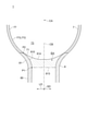
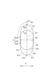
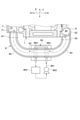
- FIG. 3 is a schematic cross-sectional view schematically showing a cross section of a high-pressure stage connection portion and a high-pressure stage housing of a connecting pipe shown in FIG. 1 as viewed from the high-pressure stage side in the axial direction. It is explanatory drawing for demonstrating the shape of the high pressure stage connection part of the connecting pipe shown in FIG. It is a schematic diagram schematically showing the vicinity of the connecting pipe in the multi-stage electric centrifugal compressor according to one embodiment of the present disclosure. It is a schematic block diagram which shows schematic structure of the multi-stage electric centrifugal compressor which concerns on one Embodiment of this disclosure.
- FIG. 5 is a schematic cross-sectional view schematically showing a cross section of the high pressure step housing shown in FIG. 5 as viewed from the high pressure step side in the axial direction. It is a schematic diagram schematically showing the vicinity of the high pressure stage housing in the multistage electric centrifugal compressor according to one embodiment of the present disclosure. It is a schematic block diagram which shows schematic structure of the multi-stage electric centrifugal compressor which concerns on one Embodiment of this disclosure.
- FIG. 8 is a schematic cross-sectional view of the vicinity of the sleeve on the high pressure stage side in FIG. It is a schematic block diagram which shows schematic structure of the multi-stage electric centrifugal compressor which concerns on one Embodiment of this disclosure.
- FIG. 5 is a schematic cross-sectional view schematically showing a cross section of the high pressure step housing shown in FIG. 5 as viewed from the high pressure step side in the axial direction. It is a schematic diagram schematically showing the vicinity of the high pressure stage housing in the multistage electric centrifug
- FIG. 10 is a schematic cross-sectional view of the vicinity of the sleeve on the high pressure stage side in FIG. It is a schematic block diagram which shows schematic structure of the multi-stage electric centrifugal compressor which concerns on one Embodiment of this disclosure. It is a schematic block diagram which shows schematic structure of the multi-stage electric centrifugal compressor which concerns on one Embodiment of this disclosure.
- expressions such as “same”, “equal”, and “homogeneous” that indicate that things are in the same state not only represent exactly the same state, but also have tolerances or differences to the extent that the same function can be obtained. It shall also represent the existing state.
- an expression representing a shape such as a quadrangular shape or a cylindrical shape not only represents a shape such as a quadrangular shape or a cylindrical shape in a geometrically strict sense, but also an uneven portion or a chamfer within the range where the same effect can be obtained. It shall also represent the shape including the part and the like.
- the expression “includes”, “includes”, or “has” one component is not an exclusive expression that excludes the existence of another component.
- the same reference numerals may be given to the same configurations, and the description thereof may be omitted.
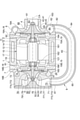
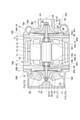
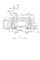
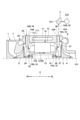
- FIG. 1 is a schematic configuration diagram schematically showing a configuration of a multi-stage electric centrifugal compressor according to an embodiment of the present disclosure.
- FIG. 1 the cross section of the multi-stage electric centrifugal compressor 1 along the axis CA of the rotary shaft 3 is schematically shown.
- the multi-stage electric centrifugal compressor 1 according to some embodiments of the present disclosure uses an impeller (low-pressure stage impeller 4, high-pressure stage impeller 5) provided at both ends of the rotary shaft 3 as an electric motor. It is configured to be driven by 10.
- the multi-stage electric centrifugal compressor 1 includes a rotary shaft 3, a low-pressure stage impeller 4 provided on one side of the rotary shaft 3 (right side in FIG. 1), and the other side of the rotary shaft 3 (on the right side in FIG. 1).
- the high-pressure stage impeller 5 provided on the left side in FIG. 1), the low-pressure stage housing 6 configured to accommodate the low-pressure stage impeller 4, and the high-pressure stage housing 7 configured to accommodate the high-pressure stage impeller 5.
- a connecting pipe 8 for supplying the compressed gas compressed by the low-pressure stage impeller 4 to the high-pressure stage housing 7 is provided at least.
- the direction in which the axis CA of the rotating shaft 3 extends is defined as the axial direction X
- the direction orthogonal to the axis CA is defined as the radial direction Y.
- the side where the low pressure stage impeller 4 is located with respect to the high pressure stage impeller 5 is the low pressure stage side XL
- the side opposite to the low pressure stage side XL is high pressure.
- the stage side XH is the side where the low pressure stage impeller 4 is located with respect to the high pressure stage impeller 5
- the stage side XH is high pressure.
- the electric motor 10 mounted on the multi-stage electric centrifugal compressor 1 includes a rotating body 11 which is a rotor and a motor stator 12 which is a stator.
- the rotating body 11 includes at least a rotating shaft 3 and a rotor assembly 13 attached to the outer periphery of the rotating shaft 3.
- the rotor assembly 13 includes a permanent magnet 14.
- the motor stator 12 includes a motor coil (stator coil) 121, and is configured to generate a magnetic field for rotating a rotating body 11 on which a permanent magnet 14 is mounted by electric power supplied from a power source (not shown).
- the impellers low pressure stage impeller 4 and high pressure stage impeller 5 attached to the rotating shaft 3 rotate in conjunction with each other. do.
- the multi-stage electric centrifugal compressor 1 compresses the gas introduced into the low-pressure stage housing 6 by rotating the low-pressure stage impeller 4, and pressurizes the gas to the first pressure.
- the compressed gas pressurized to the first pressure is guided to the inside of the high-pressure stage housing 7 through the connecting pipe 8.
- the multi-stage electric centrifugal compressor 1 further compresses the compressed gas introduced into the inside of the high-pressure stage housing 7 by rotating the high-pressure stage impeller 5, and the compressed gas has a second pressure higher than the first pressure. Pressurize to.
- the multi-stage electric centrifugal compressor 1 includes a rotor assembly 13 mounted on the rotary shaft 3, a motor stator 12 arranged so as to surround the outer periphery of the rotor assembly 13, and at least one bearing that rotatably supports the rotary shaft 3. It further comprises 15, an at least one bearing housing 16 configured to accommodate at least one bearing 15, and a stator housing 17 configured to accommodate an electric motor 10 (motor stator 12). At least one bearing housing 16 and a stator housing 17 are arranged between the low pressure stage housing 6 and the high pressure stage housing 7 in the axial direction X. The stator housing 17 is arranged adjacent to at least one bearing housing 16 in the axial direction X. The motor stator 12 is supported by the stator housing 17 inside the stator housing 17.
- the at least one bearing 15 is a low pressure stage side bearing 15A arranged between the low pressure stage impeller 4 and the rotor assembly 13 in the axial direction X, and the high pressure stage impeller 5 and the rotor in the axial direction X.
- the at least one bearing housing 16 includes a low-pressure stage bearing housing 16A configured to accommodate the low-pressure stage bearing 15A, a high-pressure stage bearing housing 16B configured to accommodate the high-pressure stage bearing 15B, and the like. including.
- the low-voltage stage bearing 15A is supported by a bearing support surface 161 formed inside the low-voltage stage bearing housing 16A.
- the high-pressure stage side bearing 15B is supported by a bearing support surface 162 formed inside the high-pressure stage side bearing housing 16B.
- the low-voltage stage bearing housing 16A is arranged on the high-pressure stage side XH of the low-pressure stage housing 6 and on the low-pressure stage side XL of the stator housing 17.
- the low-pressure stage bearing housing 16A is mechanically connected to the low-pressure stage housing 6 and the stator housing 17 arranged adjacent to the low-pressure stage bearing housing 16A in the axial direction X by a fastening member such as a fastening bolt.
- the high-voltage stage bearing housing 16B is arranged on the low-voltage stage side XL of the high-voltage stage housing 7 and on the high-voltage stage side XH of the stator housing 17.
- the high-pressure stage bearing housing 16B is mechanically connected to the high-pressure stage housing 7 and the stator housing 17 arranged adjacent to the high-pressure stage bearing housing 16B in the axial direction X by a fastening member such as a fastening bolt. There is.
- the multi-stage electric centrifugal compressor 1 has a low-pressure stage side sleeve 18A attached to the outer periphery of the rotary shaft 3 between the low-pressure stage impeller 4 and the low-pressure stage side bearing 15A in the axial direction X. Between the high-pressure stage impeller 5 and the high-pressure stage side bearing 15B in the axial direction X, the high-pressure stage side sleeve 18B attached to the outer periphery of the rotary shaft 3 and the high-pressure stage side bearing 15B are urged to the low-pressure stage side XL. A pressure spring 19 is further provided.
- the above-mentioned rotating body 11 further includes a low-pressure stage side sleeve 18A and a high-pressure stage side sleeve 18B.
- the low-pressure stage side bearing housing 16A extends inward in the radial direction from the inner surface (sleeve facing surface) 163 facing the outer peripheral surface of the low-pressure stage side sleeve 18A and the end portion of the low-pressure stage side XL of the bearing support surface 161. It also has a locking surface 164 to which the low pressure stage bearing 15A is locked.
- the inner surface 163 is formed to have a smaller diameter than the bearing support surface 161.
- the high-pressure stage side bearing housing 16B extends inward in the radial direction from the inner surface (sleeve facing surface) 165 facing the outer peripheral surface of the high-pressure stage side sleeve 18B and the end of the high-pressure stage side XH of the bearing support surface 162.
- the inner surface 165 is formed to have a smaller diameter than the bearing support surface 162.
- the above-mentioned pressurization spring 19 is arranged between the locking surface 166 and the high-pressure stage bearing 15B, and applies a predetermined pressurization to the high-pressure stage bearing 15B.
- the low-pressure stage housing 6 has a low-pressure stage inlet opening 61 for introducing gas from the outside to the inside of the low-pressure stage housing 6 and for discharging gas from the inside of the low-pressure stage housing 6 to the outside.
- Low-voltage stage outlet opening 62 and is formed.
- a supply flow path 63 for guiding the gas introduced into the inside of the low-pressure stage housing 6 from the low-pressure stage inlet opening 61 to the low-pressure stage impeller 4, and the gas that has passed through the low-pressure stage impeller 4 are introduced.
- a scroll flow path 64 for leading to the low pressure stage outlet opening 62 is formed.
- the low pressure step inlet opening 61 opens toward the low pressure step side XL in the axial direction X.
- the low-voltage stage outlet opening 62 opens in a direction intersecting (for example, orthogonal to) the axis CA.
- the low pressure stage impeller 4 has a hub 41 mechanically connected to one side of the rotary shaft 3 and a plurality of impeller blades 43 provided on the outer peripheral surface 42 of the hub 41.
- the low-pressure stage impeller 4 can rotate integrally with the rotary shaft 3 about the axis CA of the rotary shaft 3.
- the low-pressure stage impeller 4 comprises a centrifugal type impeller configured to guide the gas sent from the low-pressure stage side XL along the axial direction X to the outside in the radial direction Y.
- a gap (clearance) is formed between each of the tips 44 of the plurality of impeller blades 43 and the shroud surface 65 which is curved in a convex shape of the low pressure stage housing 6.
- the low-pressure stage housing 6 is combined with another member (in the illustrated example, the low-pressure stage side bearing housing 16A) to rotatably accommodate the low-pressure stage impeller chamber.
- 66 is formed.
- the low-pressure stage impeller chamber 66 communicates with a supply flow path 63 located on the upstream side in the gas flow direction and a scroll flow path 64 located on the downstream side in the gas flow direction.
- the scroll flow path 64 has a spiral shape that surrounds the outside of the low pressure stage impeller 4 in the radial direction Y.
- the shroud surface 65 defines a part of the low pressure stage impeller chamber 66.
- the high-pressure stage housing 7 has a high-pressure stage inlet opening 71 for introducing gas from the outside to the inside of the high-pressure stage housing 7 and for discharging gas from the inside of the high-pressure stage housing 7 to the outside.
- High-voltage stage outlet opening 72 and the above are formed inside the high-pressure stage housing 7, a supply flow path 73 for guiding the gas introduced into the inside of the high-pressure stage housing 7 from the high-pressure stage inlet opening 71 to the high-pressure stage impeller 5, and the gas that has passed through the high-pressure stage impeller 5 are introduced.
- a scroll flow path 74 for leading to the high-voltage stage outlet opening 72 is formed.
- the high-voltage step inlet opening 71 and the high-voltage step exit opening 72 each open in a direction intersecting (for example, orthogonal to) the axis CA.
- the high-pressure stage impeller 5 has a hub 51 mechanically connected to the other side of the rotary shaft 3 and a plurality of impeller blades 53 provided on the outer peripheral surface 52 of the hub 51.
- the high-pressure stage impeller 5 can rotate integrally with the rotating shaft 3 about the axis CA of the rotating shaft 3.
- the high-pressure stage impeller 5 is composed of a centrifugal impeller configured to guide the gas sent from the high-pressure stage side XH along the axial direction X to the outside in the radial direction Y.
- a gap (clearance) is formed between each of the tips 54 of the plurality of impeller blades 53 and the shroud surface 75 which is curved in a convex shape of the high-pressure stage housing 7.
- the high-pressure stage housing 7 is combined with another member (high-pressure stage side bearing housing 16B in the illustrated example) to rotatably house the high-pressure stage impeller chamber.
- 76 is formed.
- the high-pressure stage impeller chamber 76 communicates with the supply flow path 73 located on the upstream side in the gas flow direction and the scroll flow path 74 located on the downstream side in the gas flow direction.
- the scroll flow path 74 has a spiral shape that surrounds the outside of the high-pressure stage impeller 5 in the radial direction Y.
- the shroud surface 75 defines a part of the high pressure stage impeller chamber 76.
- the compressed gas (for example, compressed air) that has passed through the low-pressure stage impeller 4 flows outward in the radial direction through the scroll flow path 64, and then is discharged to the outside of the low-pressure stage housing 6 from the low-pressure stage outlet opening 62.
- the connecting pipe 8 is formed in a tubular shape extending along the length direction thereof, and has a high-pressure stage side connecting portion 81 connected to the above-mentioned high-pressure stage inlet opening 71 and a low-pressure stage exit. It includes at least a low pressure stage side connecting portion 82 connected to the opening 62.
- the high-voltage stage side connection portion 81 and the low-pressure stage side connection portion 82 each extend along a direction intersecting (orthogonal in the illustrated example) with respect to the axis CA of the rotary shaft 3. ..
- the connecting pipe 8 has an intermediate portion 83 extending along the axis CA of the rotary shaft, a low-pressure stage-side curved portion 84 having a curved shape connecting the low-pressure stage-side connecting portion 82 and the intermediate portion 83, and a high-pressure stage-side connection. Further includes a high-pressure step-side curved portion 85 having a curved shape connecting the portion 81 and the intermediate portion 83.
- the boundary of each part in the connecting pipe 8 is shown by a two-dot chain line.
- Each part in the connecting pipe 8 may be composed of separate members, or may be integrally formed of a single material.
- the compressed gas discharged from the low-pressure stage outlet opening 62 of the low-pressure stage housing 6 flows from the low-pressure stage side connection portion 82 toward the high-pressure stage side connection portion 81 of the connecting pipe 8, and then flows to the high-pressure stage inlet of the high-pressure stage housing 7. It is guided to the supply flow path 73 through the opening 71.
- the compressed gas guided to the supply flow path 73 is sent to the high-pressure stage impeller 5, compressed by the rotation of the high-pressure stage impeller 5, and pressurized to a second pressure higher than the first pressure.
- the compressed gas that has passed through the high-pressure stage impeller 5 flows outward in the radial direction through the scroll flow path 74, and then is discharged to the outside of the high-pressure stage housing 7 from the high-pressure stage outlet opening 72.
- the multi-stage electric centrifugal compressor 1 comprises a multi-stage electric centrifugal compressor for a fuel cell vehicle. Therefore, the multi-stage electric centrifugal compressor 1 further includes a compressed gas supply line 21 for supplying the compressed gas compressed by the high-pressure stage impeller 5 to the fuel cell 20.
- the fuel cell 20 comprises, for example, a solid oxide fuel cell (SOFC) and has an air electrode 201, a fuel electrode 202, and a solid electrolyte 203 provided between the air electrode 201 and the fuel electrode 202.
- SOFC solid oxide fuel cell
- the compressed gas discharged from the high-pressure stage outlet opening 72 of the high-pressure stage housing 7 is supplied to the fuel cell 20 through the compressed gas supply line 21 connecting the high-pressure stage outlet opening 72 and the air electrode 201 of the fuel cell 20.
- the present disclosure may be applied to a multi-stage electric centrifugal compressor other than that for a fuel cell vehicle, for example, a multi-stage electric centrifugal compressor for an internal combustion engine that pressurizes a combustion gas sent to an internal combustion engine such as an engine. That is, the compressed gas supply line 21 may be configured to connect the high-pressure stage outlet opening 72 of the high-pressure stage housing 7 to an internal combustion engine (not shown).
- the multi-stage electric centrifugal compressor 1 includes a rotary shaft 3, a low-pressure stage impeller 4 provided on one side of the rotary shaft 3 (low-pressure stage side XL), and a low-pressure stage impeller 4.
- the high-pressure stage impeller 5 provided on the other side (high-pressure stage side XH) of the rotary shaft 3, the high-pressure stage housing 7 for accommodating the high-pressure stage impeller 5, and the compressed gas compressed by the low-pressure stage impeller 4 are stored in the high-pressure stage housing 7. It is provided with at least a connecting pipe 8 for supplying to.
- the high-voltage stage housing 7 described above has a high-pressure stage inlet opening 71 that opens in a direction intersecting (for example, orthogonal to) the axis CA of the rotary shaft 3.
- the above-mentioned connecting pipe 8 includes a high-pressure stage side connecting portion 81 connected to the high-pressure stage inlet opening 71.
- the high-pressure step housing 7 is opened with a high-pressure step inlet opening 71 in a direction intersecting the axis CA of the rotary shaft 3, and the high pressure of the pipe 8 is connected to the high-pressure step inlet opening 71.
- the step side connection portion 81 is connected. Therefore, the compressed gas compressed by the low-pressure stage impeller 4 is supplied to the inside of the high-pressure stage housing 7 from the outer peripheral side (outside in the radial direction Y) of the high-pressure stage housing 7 through the connecting pipe 8.
- the length of the connecting pipe 8 and the high-pressure stage housing 7 in the axial direction X is shorter than that in the case where the compressed gas is introduced into the high-pressure stage housing 7 along the axial direction X of the rotary shaft 3. Can be.
- the length of the multi-stage electric centrifugal compressor 1 in the axial direction X can be shortened, so that the multi-stage electric centrifugal compressor 1 can be made smaller and lighter.
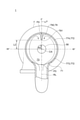
- FIG. 2 is a schematic cross-sectional view schematically showing a cross section of the high-pressure stage connection portion and the high-pressure stage housing of the connecting pipe shown in FIG. 1 as viewed from the high-pressure stage side in the axial direction.
- FIG. 3 is an explanatory diagram for explaining the shape of the high-pressure stage connection portion of the connecting pipe shown in FIG.
- the flow path cross section eg, flow path cross section 813, 814 of the high voltage stage side connection portion 81 described above is orthogonal to the axis CA of the rotary shaft 3. It has a longitudinal LD along the direction and includes convex curved portions 811 and 812 formed on both ends of the longitudinal LD.
- the high-voltage stage side connection portion 81 described above has an enlarged region EA in which the cross-sectional area of the flow path increases toward the high-voltage stage inlet opening 71 side.
- This enlarged area EA is defined by the inner wall surface 810 of the high voltage stage side connecting portion 81.
- one side connected to the high-voltage stage inlet opening 71 is the end point P2 of the expansion region EA, and the opposite side to the one side is the start point P1 of the expansion region EA. It has become.
- the flow path cross section 813 is a flow path cross section at the start point P1 of the expansion region EA
- the flow path cross section 814 is a flow path cross section at the end point P2 of the expansion region EA.
- the flow path cross section of the high-voltage stage side connection portion 81 has a longitudinal LD along a direction orthogonal to the axis CA of the rotary shaft 3 and is formed on both ends of the longitudinal LD. Includes the convex curved portions 811 and 812.
- the cross section of the flow path of the high-voltage stage side connection portion 81 has an elliptical shape extending along the longitudinal direction LD, the high-pressure stage side connection portion 81 becomes large in the axial direction X of the rotary shaft 3.
- the flow path area of the high-voltage stage side connection portion 81 can be increased while suppressing the pressure.
- the pressure of the compressed gas flowing through the high-pressure step side connection portion 81 is higher than that in the case where the cross section of the flow path is a polygon such as a rectangle. Loss can be suppressed.
- the flow path cross section (eg, flow path cross section 813, 814) of the high voltage stage side connection portion 81 described above is short along the axis CA of the rotary shaft 3.
- the cross section of the flow path of the high-voltage stage side connection portion 81 has a shape having the short side SD along the axis CA, so that the length of the rotary shaft 3 of the high-voltage stage side connection portion 81 in the axial direction X is long. The length can be shortened, and the size and weight of the multi-stage electric centrifugal compressor 1 can be reduced.
- the flow path cross section (eg, flow path cross section 813, 814) of the high pressure stage side connection portion 81 described above is the end portion of the pair of convex curved portions 811 and 812. Further includes a straight portion 815 connecting the two.
- the straight portion 815 has a predetermined length L1 in the longitudinal direction LD, and has the same length in the lateral direction SD.
- the cross section of the flow path of the high-pressure stage side connection portion 81 includes the straight portion 815, the speed component of the compressed gas flowing through the high-pressure stage side connection portion 81 toward the high-pressure stage inlet opening 71 side is large.
- the compressed gas can be smoothly flowed into the high-pressure stage impeller 5 from the high-pressure stage inlet opening 71.
- the pressure loss of the compressed gas at the connection portion between the high pressure stage side connection portion 81 and the high pressure stage inlet opening 71 can be reduced.
- the length of the longitudinal LD in the flow path cross section 814 (end point P2 of the enlarged region EA) is larger than the length of the longitudinal LD in the flow path cross section 813 (start point P1 of the enlarged region EA).
- the variation in the length of the SD in the lateral direction is small from the start point P1 to the end point P2 of the expansion region EA, and the length of the LD in the longitudinal direction is increased, so that the cross-sectional area of the flow path is expanded. ..
- the flow path cross section of the high-voltage stage side connection portion 81 is formed so that the length in the longitudinal direction increases toward the high-voltage stage inlet opening 71 side, whereby the high-voltage stage side connection portion 81 of the high-voltage stage side connection portion 81 is formed.
- the compressed gas flowing along the inner wall surface 810 can be flowed as it is along the inner wall surface 77 defining the supply flow path 73 of the high-pressure stage housing 7.
- the high-pressure step inlet opening 71 described above is formed on an inner peripheral wall surface 772 that defines the outer peripheral side of the supply flow path 73.
- the inner wall surface 810 of the high-voltage stage side connection portion 81 and the inner peripheral wall surface 772 of the high-voltage stage housing 7 are gently connected to each other.
- smoothly connected means that the corner portion is not formed at the boundary between the inner wall surface 77 and the inner peripheral wall surface 772 and is rounded.
- the inner wall surface 810 has a convex curved shape.
- the curvature of the portion connected to the inner wall surface 77 of the inner peripheral wall surface 772 is as large as possible. It is preferable to make it larger. According to the above configuration, since the inner wall surface 810 of the high-voltage stage side connection portion 81 and the inner peripheral wall surface 772 of the high-voltage stage housing 7 are gently connected, the high-voltage stage side connection portion 81 and the high-voltage stage inlet opening The pressure loss of the compressed gas at the connection portion with the 71 can be reduced.
- the flow path cross section of the high-voltage stage side connection portion 81 described above increases the maximum curvature of the convex curved portions 811 and 812 toward the high-voltage stage inlet opening 71 side.
- the maximum curvature R2 of the convex curved portions 811 and 812 in the flow path cross section 814 is the convex curved portion 811 in the flow path cross section 813 (start point P1 of the enlarged region EA). It is larger than the maximum curvature R1 of 812.
- the convex curved portions 811 and 812 in the flow path cross section 813 are formed so that their curvatures are equal from the connection end with the straight portion 815 to one end of the longitudinal LD. ..
- the curvatures of the convex curved portions 811 and 812 in the flow path cross section 814 increase from the connection ends 816 and 818 with the straight portion 815 toward one ends 817 and 819 of the longitudinal LD. It is formed.
- the maximum curvature R2 is more than twice the maximum curvature R1.
- the flow path cross section of the high-voltage stage side connection portion 81 is formed so that the maximum curvatures of the convex curved portions 811 and 812 increase toward the high-voltage stage inlet opening 71 side, thereby increasing the high-voltage stage side.
- the compressed gas flowing through the connection portion 81 can be smoothly guided to the high-pressure stage inlet opening 71.
- the pressure loss of the compressed gas at the connection portion between the high pressure stage side connection portion 81 and the high pressure stage inlet opening 71 can be reduced.
- the above-mentioned connecting pipe 8 has the above-mentioned high-pressure stage side connection portion 81, the above-mentioned low-pressure stage side connection portion 82, the above-mentioned intermediate portion 83, and the above-mentioned intermediate portion 83.
- the low-pressure step-side curved portion 84 and the high-pressure step-side curved portion 85 described above are included.
- At least the cross section of the flow path of the low pressure stage side connection portion 82 is formed in a circular shape. In the illustrated embodiment, not only the low pressure stage side connection portion 82 but also the flow path cross sections of the low pressure stage side connection portion 82 and the intermediate portion 83 are formed in a circular shape. Further, in the high-voltage step side curved portion 85, the cross section of the flow path changes from a circular shape to an oval shape.
- the compressed gas sent from the low pressure stage housing 6 to the connecting pipe (8) has a swirling component.
- the pressure loss of the compressed gas having a swirling component flowing through the connecting pipe 8 can be reduced by forming at least the cross section of the flow path of the low pressure stage side connecting portion 82 in the connecting pipe 8 into a circular shape.
- the pressure loss of the compressed gas having a swirling component flowing through the connecting pipe 8 can be further reduced.
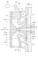
- FIG. 4 is a schematic view schematically showing the vicinity of the connecting pipe in the multi-stage electric centrifugal compressor according to the embodiment of the present disclosure.
- the cross section of the multi-stage electric centrifugal compressor 1 along the axis CA of the rotary shaft 3 is schematically shown.
- the above-mentioned multi-stage electric centrifugal compressor 1 has a compressed gas in a connecting pipe 8 and a cooling liquid (for example, cooling water) for cooling the compressed gas.
- a cooling device 86 configured to exchange heat between the and.
- the compressed gas compressed by the low-pressure stage impeller 4 is supplied to the high-pressure stage impeller 5 after being cooled by the cooling device 86.
- the cooling device 86 is configured to cool the cooling liquid circulation line 861 for circulating the cooling liquid as a cooling medium, the cooling liquid circulation pump 862 configured to send the cooling liquid, and the cooling liquid.
- the cooling liquid circulation pump 862 configured to send the cooling liquid
- the cooling liquid Includes a radiator 863, and is configured in.
- the coolant circulation line 861 has a heat exchange unit 864 that exchanges heat between the compressed gas in the connecting pipe 8 and the coolant.
- the coolant circulation pump 862 is arranged on the upstream side in the flow direction of the coolant with respect to the heat exchange unit 864 in the coolant circulation line 861 so as to send the coolant to the downstream side.
- the radiator 863 is arranged on the upstream side of the heat exchange unit 864 in the coolant circulation line 861 in the flow direction of the coolant, and cools the coolant heated by heat exchange with the compressed gas.
- the cooling liquid in the heat exchange unit 864 has a lower temperature than the compressed gas in the connecting pipe 8 to be heat exchanged.
- the cooling device 86 is not limited to the illustrated embodiment as long as heat exchange is possible between the compressed gas in the connecting pipe 8 and the cooling liquid.
- the compressed gas flowing through the connecting pipe 8 is cooled by heat exchange between the compressed gas in the connecting pipe 8 and the cooling liquid in the cooling device 86.
- the cooling device 86 By lowering the temperature of the compressed gas sent to the high-pressure stage impeller 5 by the cooling device 86, it is possible to suppress the temperature rise of the compressed gas after passing through the high-pressure stage impeller 5.
- This makes it possible to improve the compression ratio in the high-pressure stage of the multi-stage electric centrifugal compressor 1.
- the high-pressure stage impeller 5 The amount of heat input from the back surface 57 to the bearing 15 (particularly, the high-pressure stage side grease-filled bearing 15B) can be reduced. As a result, deterioration of the bearing 15 due to heat can be suppressed, so that the life and durability of the bearing 15 can be improved.
- the high pressure stage housing 7 described above defines a supply flow path 73 for guiding the compressed gas supplied from the high pressure stage inlet opening 71 to the high pressure stage impeller 5.
- the inner wall surface 77 defines an inner end wall surface 771 that defines the side of the supply flow path 73 opposite to the high pressure stage impeller 5 (high pressure stage side XH) and an outer peripheral side (outer side in the radial direction Y) of the supply flow path 73.
- the inner peripheral wall surface 772 and the like are included.
- the high-pressure step housing 7 described above further includes a guide convex portion 78 projecting from the inner end wall surface 771 toward the high-pressure step impeller 5.
- the outer peripheral surface of the guide convex portion 78 is formed in a concave curved shape.
- the compressed gas flowing through the supply flow path 73 of the high-pressure stage housing 7 can be guided to the high-pressure stage impeller 5 by the guide convex portion 78 protruding from the inner end wall surface 771 toward the high-pressure stage impeller 5.
- the flow of the compressed gas flowing inward in the radial direction Y along the inner end wall surface 771 is bent along the outer peripheral surface of the guide convex portion 78, and flows toward the low pressure stage side XL in the axial direction X. Can be changed to.
- the compressed gas can be introduced into the high-pressure stage impeller 5 along the axial direction by the guide convex portion 78, the compressed gas is introduced into the high-pressure stage impeller 5 from the outside in the radial direction.
- the efficiency of the electric centrifugal compressor 1 can be improved.
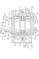
- FIG. 5 is a schematic configuration diagram schematically showing the configuration of a multi-stage electric centrifugal compressor according to an embodiment of the present disclosure.
- FIG. 6 is a schematic cross-sectional view schematically showing a cross section of the high pressure step housing shown in FIG. 5 as viewed from the high pressure step side in the axial direction.
- the cross section of the multi-stage electric centrifugal compressor 1 along the axis CA of the rotary shaft 3 is schematically shown.
- the above-mentioned inner peripheral wall surface 772 has an inlet side inner peripheral wall surface 773 in which the high-pressure step entrance opening 71 is formed, and a side opposite to the high-pressure step entrance opening 71. It has an inner peripheral wall surface 774 on the opposite side located at.
- the high-pressure stage housing 7 described above includes a swivel prevention plate 79 protruding from the inner peripheral wall surface 774 on the opposite side.
- the position of the intersection P4 with the inner peripheral wall surface 774 on the opposite side is set to the 0 ° position
- the clockwise direction around the axis CA is set to the positive direction
- the tip 791 closest to the axis CA of the swivel prevention plate 79 described above exists in the range of ⁇ 90 ° ⁇ ⁇ ⁇ 90 °.
- the anti-swivel plate 79 has an outer surface (inclined surface) 792 that inclines so that the width dimension decreases toward the tip 791.
- FIG. 6 shows the tip end 56 of the leading edge 55 of the high-pressure stage impeller 5 as corresponding to the inlet of the high-pressure stage impeller 5.
- the flow of the compressed gas flowing along the inner peripheral wall surface 772 in the supply flow path 73 in either the clockwise direction or the counterclockwise direction is along the outer surface 792 of the swivel prevention plate 79. By making it bend, it can be changed to a flow toward the entrance of the high-pressure stage impeller 5.
- the high-pressure stage housing 7 does not include the swivel prevention plate 79, the compressed gas flowing clockwise along the inner peripheral wall surface 772 of the supply flow path 73 and the inner circumference of the supply flow path 73 in the counterclockwise direction. Since the compressed gas flowing along the wall surface 772 collides with the compressed gas, there is a risk of causing pressure loss in the supply flow path 73.
- the compressed gas flowing in the supply flow path 73 of the high-pressure stage housing 7 in one direction in the circumferential direction of the rotary shaft 3 and the supply flow path 73 in the circumferential direction by the swivel prevention plate 79 are described above. It is possible to prevent the compressed gas flowing in the direction opposite to one direction from colliding with the compressed gas. Further, the swivel prevention plate 79 guides the compressed gas flowing along the inner peripheral wall surface 774 on the opposite side inward in the radial direction in which the high-pressure stage impeller 5 is located, thereby smoothing the compressed gas flowing in from the high-pressure stage inlet opening 71. It can be led to the high pressure stage impeller 5. As a result, the pressure loss of the compressed gas in the supply flow path 73 of the high-pressure stage housing 7 can be reduced.
- the tip 791 of the swivel prevention plate 79 described above is larger than the tip end 56 (corresponding to the inlet of the high pressure step impeller 5) of the leading edge 55 of the high pressure step impeller 5. It is located on the outer peripheral side of the rotary shaft 3.
- the tip 791 of the swivel prevention plate 79 is located on the inner peripheral side of the rotary shaft 3 with respect to the tip end 56 of the front edge 55 of the high pressure stage impeller 5, the high pressure stage impeller 5 is guided by the swivel prevention plate 79. Since the velocity component of the compressed gas introduced into the high pressure stage impeller 5 becomes large inward in the radial direction, the compression efficiency of the high-pressure stage impeller 5 may decrease. According to the above configuration, since the tip 791 of the swivel prevention plate 79 is located on the outer peripheral side of the rotary shaft 3 with respect to the tip end 56 of the leading edge 55 of the high pressure stage impeller 5, the high pressure is guided by the swivel prevention plate 79. The velocity component of the compressed gas introduced into the step impeller 5 inward in the radial direction can be made small. This makes it possible to suppress a decrease in compression efficiency in the high-pressure stage impeller 5.
- the distance of the tip 791 of the swivel prevention plate 79 from the axis CA of the rotary shaft 3 is L2, and the tip end.
- the radius of 56 (the length from the axis CA) is defined as R3. If the L2 is too large, the protrusion length from the inner peripheral wall surface 774 on the opposite side of the swivel prevention plate 79 becomes small, and it becomes difficult for the swivel prevention plate 79 to change the flow of the compressed gas.
- the above L2 satisfies the condition of 1.5R3 ⁇ L2 ⁇ 2.5R3.
- Each of the multi-stage electric centrifugal compressors 1 according to some of the following embodiments can be implemented independently. For example, it can be applied to a multi-stage electric centrifugal compressor in which the high-pressure stage inlet opening 71 opens toward the high-pressure stage side XH in the axial direction X.
- the multi-stage electric centrifugal compressor 1 according to some of the following embodiments may be combined with each other, or the configurations of the multi-stage electric centrifugal compressor 1 according to some of the above-described embodiments may be combined. You may.
- FIG. 7 is a schematic view schematically showing the vicinity of the high-pressure stage housing in the multi-stage electric centrifugal compressor according to the embodiment of the present disclosure.
- FIG. 8 is a schematic configuration diagram schematically showing the configuration of a multi-stage electric centrifugal compressor according to an embodiment of the present disclosure.
- FIG. 9 is a schematic cross-sectional view of the vicinity of the sleeve on the high pressure stage side in FIG.
- FIG. 10 is a schematic configuration diagram schematically showing the configuration of a multi-stage electric centrifugal compressor according to an embodiment of the present disclosure.
- FIG. 11 is a schematic cross-sectional view of the vicinity of the high-pressure stage side sleeve in FIG. In FIGS.
- the multi-stage electric centrifugal compressor 1 has a rotary shaft 3 and a low-pressure stage provided on one side of the rotary shaft 3 (low-pressure stage side XL).
- the impeller 4, the high-pressure stage impeller 5 provided on the other side of the rotary shaft 3 (high-pressure stage side XH), and the rotary shaft 3 are rotatably supported, and between the high-pressure stage impeller 5 and the low-pressure stage impeller 4.
- At least one bearing 15 includes a high-pressure stage side grease-filled bearing 15B arranged between the high-pressure stage impeller 5 and the electric motor 10 (rotor assembly 13).
- the high-pressure stage side bearing 15B described above comprises a grease-filled type bearing in which grease is pre-filled.
- the bearing housing 16 includes a high pressure stage bearing housing 16B that houses the high pressure stage grease filled bearing 15B.
- the multi-stage electric centrifugal compressor 1 includes a high-pressure stage side grease-filled bearing 15B in which grease is pre-filled.
- the structure of the parts around the high-pressure stage grease-filled bearing 15B (for example, the high-pressure stage side bearing housing 16B) can be simplified. As a result, the multi-stage electric centrifugal compressor 1 can be made smaller and lighter.
- the above-mentioned at least one bearing 15 includes the above-mentioned high-pressure stage side grease-filled bearing 15B and the low-pressure stage impeller. Further includes a low-pressure stage side grease-filled bearing 15A arranged between the 4 and the electric motor 10 (rotor assembly 13).
- the above-mentioned low-voltage stage bearing 15A is composed of a grease-filled type bearing in which grease is pre-filled.
- the bearing housing 16 includes the high pressure stage side bearing housing 16B described above and the low pressure stage side bearing housing 16A for accommodating the low pressure stage side grease filled bearing 15A.
- the multi-stage electric centrifugal compressor 1 includes a low-pressure stage side grease-filled bearing 15A in which grease is pre-filled.
- the structure of the parts around the low-pressure stage grease-filled bearing 15A (for example, the low-pressure stage side bearing housing 16A) can be simplified. As a result, the multi-stage electric centrifugal compressor 1 can be made smaller and lighter.
- the bearing housing 16 (high pressure stage side bearing housing 16B) described above has a high pressure stage side grease filled bearing 15B and a high pressure stage impeller in the axial direction X of the rotary shaft 3. It has a cooling passage 91 formed between the 5 and 5.
- the cooling passage 91 is located on the outer peripheral side of the high pressure stage side sleeve 18B.
- the cooling passage 91 extends along the circumferential direction of the rotary shaft 3.
- the cooling passage 91 may be formed in an annular shape or in an arc shape in a cross section along a direction orthogonal to the axis CA.
- the cooling passage 91 is filled with gas (for example, air), but the cooling passage 91 may be filled with cooling water.
- the multi-stage electric centrifugal compressor 1 may include a cooling water supply line (not shown) for supplying cooling water to the cooling passage 91.
- the bearing housing 16 (high pressure stage side bearing housing 16B) is a cooling passage formed between the high pressure stage side grease-filled bearing 15B and the high pressure stage impeller 5 in the axial direction X of the rotary shaft 3. Has 91. Therefore, the cooling passage 91 can suppress heat transfer from the back surface 57 of the high-pressure stage impeller 5 to the high-pressure stage side grease-filled bearing 15B. As a result, deterioration of the high-pressure stage grease-filled bearing 15B due to heat can be suppressed, so that the life and durability of the high-pressure stage grease-filled bearing 15B can be improved.
- the inner end of the cooling passage 91 in the radial direction Y is preferably located in the vicinity of the inner surface 165 of the high-pressure stage bearing housing 16B.
- the cooling passage described above may be formed on the low pressure stage side.
- the bearing housing 16 (low pressure stage side bearing housing 16A) described above has a low pressure stage side grease filled bearing 15A and a low pressure stage impeller in the axial direction X of the rotary shaft 3. It has a cooling passage 92 formed between the four and the fourth.
- the cooling passage 92 is located on the outer peripheral side of the low pressure stage side grease-filled bearing 15A.
- the cooling passage 92 extends along the circumferential direction of the rotary shaft 3.
- the cooling passage 92 may be formed in an annular shape or in an arc shape in a cross section along a direction orthogonal to the axis CA.
- the cooling passage 92 is filled with gas (for example, air), but the cooling passage 92 may be filled with cooling water.
- the multi-stage electric centrifugal compressor 1 may include a cooling water supply line (not shown) for supplying cooling water to the cooling passage 92.
- the bearing housing 16 (low pressure stage side bearing housing 16A) is a cooling passage formed between the low pressure stage side grease-filled bearing 15A and the low pressure stage impeller 4 in the axial direction X of the rotary shaft 3. Has 92. Therefore, the cooling passage 92 can suppress heat transfer from the back surface of the low-pressure stage impeller 4 to the low-pressure stage side grease-filled bearing 15A. As a result, deterioration of the low-pressure stage grease-filled bearing 15A due to heat can be suppressed, so that the life and durability of the low-pressure stage grease-filled bearing 15A can be improved.
- the high pressure stage housing 7 described above has a high pressure stage side cooling passage 70 formed on the outer peripheral side of the rotary shaft 3 with respect to the high pressure stage impeller 5.
- a heat medium for example, a coolant
- the high pressure stage cooling passage 70 is formed between the surface forming the inner side of the scroll flow path 64 in the radial direction and the shroud surface 65.
- the high-pressure stage side cooling passage 70 is formed in an annular shape extending along the circumferential direction of the rotary shaft 3.
- the high-pressure stage cooling passage 70 may be formed in an arc shape extending along the circumferential direction of the rotary shaft 3.
- the high-pressure stage housing 7 further has an inlet passage 701 for flowing the cooling liquid into the high-pressure stage side cooling passage 70, and an outlet passage 702 for discharging the cooling liquid from the high-pressure stage side cooling passage 70.
- the inlet passage 701 connects the coolant introduction port 703 formed on the outer surface of the high-pressure stage housing 7 and the high-pressure stage side cooling passage 70 so that the coolant can flow.
- the outlet passage 702 connects the coolant discharge port 704 formed on the outer surface of the high-pressure stage housing 7 and the high-pressure stage side cooling passage 70 so that the coolant can flow.
- the multi-stage electric centrifugal compressor 1 has a coolant supply line 705 for sending the coolant to the high-pressure stage side cooling passage 70, and cooling configured to store the coolant.
- a liquid storage device (coolant storage tank) 706 and a coolant circulation pump 707 configured to send the coolant to the downstream side of the coolant supply line 705 are provided.
- the coolant storage device 706 is arranged on the upstream side of the coolant circulation pump 707 in the coolant supply line 705.
- the downstream end of the coolant supply line 705 is connected to the coolant inlet 703 of the inlet passage 701.
- the coolant circulation pump 707 sends the coolant to the downstream side in the coolant supply line 705, so that the coolant flows into the high-pressure stage cooling passage 70 through the inlet passage 701.
- the coolant flowing into the high-pressure stage side cooling passage 70 flows through the high-pressure stage side cooling passage 70 along the circumferential direction of the rotary shaft 3, and then passes through the outlet passage 702 from the coolant discharge port 704 to the outside of the high-pressure stage housing 7. Is discharged to.
- the coolant discharged from the coolant discharge port 704 to the outside of the high-pressure stage housing 7 may be cooled by a heat exchanger or the like and then flowed into the high-pressure stage side cooling passage 70 again through the inlet passage 701.
- the compressed gas supplied to the high-pressure stage impeller 5 in the high-pressure stage housing 7 can be cooled by the high-pressure stage side cooling passage 70, and the temperature rise of the compressed gas after passing through the high-pressure stage impeller 5 is suppressed. can.
- This makes it possible to improve the compression ratio in the high-pressure stage of the multi-stage electric centrifugal compressor 1. Further, by suppressing the temperature rise of the compressed gas after passing through the high-pressure stage impeller 5, it is possible to suppress the temperature rise of the gas existing in the space 24 facing the back surface 57 of the high-pressure stage impeller 5.
- the high-pressure stage impeller 5 The amount of heat input from the back surface 57 to the bearing 15 (for example, the high-pressure stage side grease-filled bearing 15B) can be reduced. As a result, deterioration of the bearing 15 due to heat can be suppressed, so that the life and durability of the bearing 15 can be improved.
- the high pressure stage side bearing housing 16B (bearing housing 16) described above has a first pressure relief hole 93.
- the first pressure relief hole 93 is the first inner opening 931 formed on the inner surface 165 of the high pressure stage side bearing housing 16B facing the outer peripheral surface of the rotating body 11 including the rotary shaft 3, and the high pressure stage side bearing housing 16B. It has a first outer opening 932 formed on the outer surface 168.
- the first inner opening 931 is formed between the high-pressure stage side grease-filled bearing 15B and the high-pressure stage impeller 5 in the axial direction X of the rotary shaft 3.
- a space 24 is formed between the back surface 57 of the high-pressure stage impeller 5 and the high-pressure stage side surface 167 of the high-pressure stage side bearing housing 16B facing the back surface 57. Further, a gap 25 is formed between the outer peripheral surface 181 of the high-pressure stage side sleeve 18B and the inner surface 165 of the high-pressure stage side bearing housing 16B facing the outer peripheral surface 181. The gap 25 communicates with the space 24.
- the second annular groove 183 is formed on the low pressure stage side XL (right side in FIG. 9) in the axial direction X with respect to the first annular groove 182.
- the outer surface of each of the first seal member 22 and the second seal member 23 is in contact with the outer peripheral surface 181 of the high-pressure stage side sleeve 18B, and the gap 25 is divided into a plurality of parts.
- the first inner opening 931 is located between the first annular groove 182 and the second annular groove 183 in the axial direction X.
- the gas existing in the space 24 rises and rises. If the gas existing in the space 24 passes through the gap 25 and flows to the high-pressure stage side grease-filled bearing 15B, the high-pressure stage side grease-filled bearing 15B may be deteriorated by heat.
- the high-pressure stage side bearing housing 16B (bearing housing 16) includes a first inner opening 931 formed on the inner surface 165 and a first outer opening 932 formed on the outer surface 168. It has a first pressure relief hole 93 having a housing.
- the first inner opening 931 is formed between the high-pressure stage side grease-filled bearing 15B and the high-pressure stage impeller 5 in the axial direction of the rotary shaft 3. In this case, the pressure leak from the space 24 facing the back surface 57 of the high-pressure stage impeller 5 can flow to the outside of the high-pressure stage side bearing housing 16B (bearing housing 16) through the first pressure relief hole 93.
- the high-temperature and high-pressure gas leaking from the space 24 into the gap 25 separated between the first seal member 22 and the second seal member 23 is air existing outside the high-pressure stage bearing housing 16B. It is guided to the first pressure release hole 93 through the first inner opening 931 by the pressure difference with the first outer opening 932, and is discharged to the outside of the high pressure stage side bearing housing 16B from the first outer opening 932. In this case, it is possible to prevent pressure leakage from the space 24 facing the back surface 57 of the high-pressure stage impeller 5 from flowing to the high-pressure stage side grease-filled bearing 15B. As a result, deterioration of the high-pressure stage grease-filled bearing 15B due to heat can be suppressed, so that the life and durability of the high-pressure stage grease-filled bearing 15B can be improved.
- the above-mentioned pressure relief hole may be formed on the low pressure stage side.
- the low pressure stage side bearing housing 16A (bearing housing 16) described above has a second pressure relief hole 94.
- the second pressure relief hole 94 is formed on the inner surface 163 of the high pressure stage side bearing housing 16B facing the outer peripheral surface of the rotating body 11 including the rotary shaft 3 (in the illustrated example, the outer peripheral surface 184 of the low pressure stage side sleeve 18A). It has a second inner opening 941 and a second outer opening 942 formed on the outer surface 169 of the low pressure stage bearing housing 16A.
- the second inner opening 941 is formed between the low-pressure stage side grease-filled bearing 15A and the high-pressure stage impeller 5 in the axial direction X of the rotary shaft 3.
- the second inner opening 941 may be formed between the two sealing members mounted on the low pressure step side sleeve 18A in the axial direction X, similarly to the first inner opening 931.
- the low pressure stage side bearing housing 16A (bearing housing 16) includes a second inner opening 941 formed on the inner surface 163 and a second outer opening 942 formed on the outer surface 169. It has a second pressure relief hole 94 having a housing.
- the second inner opening 941 is formed between the low-pressure stage side grease-filled bearing 15A and the low-pressure stage impeller 4 in the axial direction of the rotary shaft 3. In this case, the pressure leak from the space facing the back surface of the low pressure stage impeller 4 can flow to the outside of the low pressure stage side bearing housing 16A (bearing housing 16) through the second pressure relief hole 94.
- the suction may be forcibly sucked from the first pressure release hole 93 or the second pressure release hole 94.
- the multi-stage electric centrifugal compressor 1 may include a negative pressure source (not shown) and a pipe connecting at least one of the first pressure release hole 93 or the second pressure release hole 94 to the negative pressure source. good.
- the high pressure stage side bearing housing 16B (bearing housing 16) described above has a first pressure applying hole 95.
- the first pressure-applied hole 95 has a third inner opening 951 formed on the inner surface 165 of the high-pressure stage bearing housing 16B facing the outer peripheral surface 181 of the rotating body 11 including the rotating shaft 3, and the high-pressure stage bearing housing 16B. It has a third outer opening 952, which is formed on the outer surface 168 of the.
- the third inner opening 951 is formed between the high-pressure stage side grease-filled bearing 15B and the high-pressure stage impeller 5 in the axial direction X of the rotary shaft 3.
- the multi-stage electric centrifugal compressor 1 described above includes a pressure introduction line 26 configured to introduce pressure from a pressure source (for example, a compressed gas supply line 21 or a surge tank 27) into the third inner opening 951.
- a pressure source for example, a compressed gas supply line 21 or a surge tank 27
- a space 24 is formed between the back surface 57 of the high-pressure stage impeller 5 and the high-pressure stage side surface 167 of the high-pressure stage side bearing housing 16B facing the back surface 57. Further, a gap 25 is formed between the outer peripheral surface 181 of the high-pressure stage side sleeve 18B and the inner surface 165 of the high-pressure stage side bearing housing 16B facing the outer peripheral surface 181. The gap 25 communicates with the space 24.
- a first annular groove in which a first sealing member (for example, an annular seal ring) 22 is fitted is fitted on the outer peripheral surface 181 of the high pressure stage side sleeve 18B. It has 182 and a second annular groove 183 into which a second sealing member (eg, an annular seal ring) 23 fits.
- the second annular groove 183 is formed on the low pressure stage side XL (right side in FIG. 11) in the axial direction X with respect to the first annular groove 182.
- each of the first seal member 22 and the second seal member 23 is in contact with the outer peripheral surface 181 of the high-pressure stage side sleeve 18B, and the gap 25 is divided into a plurality of parts. Further, in the illustrated embodiment, the third inner opening 951 is located between the first annular groove 182 and the second annular groove 183 in the axial direction X.
- the pressure introduction line 26 is configured to introduce pressure from each of the compressed gas supply line 21 and the surge tank 27 into the third outer opening 952.
- the gas in the surge tank 27 has a higher pressure than the space 24 due to the compressor 28.
- One side of the pressure introduction line 26 is connected to the branch portion 211 of the compressed gas supply line 21, and the other side is connected to the third outer opening.
- One side is connected to the first pipe 261 and the other side is connected to the first pipe 261.
- a switching device 263 configured to switch the pressure supply source to the second pipe 262 connected to the surge tank 27 and the third outer opening 952 to either the compressed gas supply line 21 or the surge tank 27. And.
- the switching device 263 may be a three-way valve provided at the connection portion between the first pipe 261 and the second pipe 262 as shown in FIG. 10, or the connection of the first pipe 261 to the second pipe 262. It may be a valve (for example, an on-off valve) provided on the upstream side of the portion and on each of the second pipe 262.
- the pressure introduction line 26 includes a pipe one side connected to the surge tank 27 and the other side connected to a third outer opening, from the surge tank 27 only to the third outer side. It may be configured to introduce pressure into the opening 952. By introducing pressure from the compressed gas supply line 21 to the third outer opening 952, the capacity of the surge tank 27 can be reduced.
- the gas existing in the space 24 rises and rises. If the gas existing in the space 24 passes through the gap 25 and flows to the high-pressure stage side grease-filled bearing 15B, the high-pressure stage side grease-filled bearing 15B may be deteriorated by heat.
- the high-pressure stage side bearing housing 16B (bearing housing 16) includes a third inner opening 951 formed on the inner surface 165 and a third outer opening 952 formed on the outer surface 168. It has a first pressure-applying hole 95 having a bearing.
- the third inner opening 951 is formed between the high-pressure stage side grease-filled bearing 15B and the high-pressure stage impeller 5 in the axial direction of the rotary shaft 3.
- the multi-stage electric centrifugal compressor 1 includes the pressure introduction line 26. In this case, by introducing the pressure from the pressure source into the third outer opening 952 through the pressure introduction line 26, the pressure in the gap 25 formed between the outer peripheral surface 181 and the 165 is applied.
- the pressure in the space 24 facing the back surface 57 of the high pressure stage impeller 5 can be higher than the pressure.
- deterioration of the high-pressure stage grease-filled bearing 15B due to heat can be suppressed, so that the life and durability of the high-pressure stage grease-filled bearing 15B can be improved.
- the pressure in the gap 25 higher than the pressure in the space accommodating the high-pressure stage side grease-filled bearing 15B, the grease sealed in the high-pressure stage side grease-filled bearing 15B is made into the gap 25 and the space 24. It is possible to prevent leakage to the flow path through which the compressed gas flows. As a result, it is possible to prevent grease from being mixed into the compressed gas compressed by the multi-stage electric centrifugal compressor 1, so that the multi-stage electric centrifugal compressor 1 can supply a clean compressed gas to the fuel cell 20 and the like.
- the above-mentioned high-pressure stage side bearing housing 16B (bearing housing 16) further has a third pressure relief hole 96.
- the third pressure relief hole 96 is formed in the inner opening 961 formed on the high pressure stage side (left side in the figure) of the high pressure stage side grease-filled bearing 15B on the bearing support surface 162 and the outer surface 168 of the high pressure stage side bearing housing 16B. It has an outer opening 962 formed.
- the inner opening 961 faces the space formed between the high-pressure stage side sleeve 18B and the high-pressure stage side grease-filled bearing 15B.
- the high-pressure gas leaked to is guided to the third pressure relief hole 96 through the inner opening 961 by the pressure difference with the air existing outside the high-pressure stage bearing housing 16B, and the high-pressure stage bearing housing 16B is guided from the outer opening 962. Can be discharged to the outside of. In this case, it is possible to suppress the pressure leakage from the gap 25 from flowing to the high-pressure stage side grease-filled bearing 15B.
- the pressure applying hole described above may be formed on the low pressure stage side.
- the low pressure stage side bearing housing 16A (bearing housing 16) described above has a second pressure applying hole 97.
- the second pressure applying hole 97 is formed on the inner surface 163 of the high pressure stage side bearing housing 16B facing the outer peripheral surface of the rotating body 11 including the rotating shaft 3 (in the illustrated example, the outer peripheral surface 184 of the low pressure stage side sleeve 18A). It has an inner opening 971 and an outer opening 972 formed on the outer surface 169 of the low pressure stage bearing housing 16A.
- the inner opening 971 is formed between the low-pressure stage side grease-filled bearing 15A and the low-pressure stage impeller 4 in the axial direction X of the rotary shaft 3.
- the inner opening 971 may be formed between the two sealing members mounted on the low pressure step side sleeve 18A in the axial direction X, similarly to the third inner opening 951.
- the multi-stage electric centrifugal compressor 1 further includes a pressure introduction line 29 configured to introduce pressure from a pressure source (for example, a compressed gas supply line 21 or a surge tank 27) to the outer opening 972.
- a pressure source for example, a compressed gas supply line 21 or a surge tank 27
- the pressure introduction line 29 shares some equipment (pipes and valves) with the pressure introduction line 26 described above. That is, one side of the pressure introduction line 29 is connected to the branch portion 264 located between the connection portion with the second pipe 262 and the third outer opening 952 in the first pipe 261 and the other side is connected to the outer opening 972.
- a third pipe 291 to be connected and a pressure reducing valve 292 provided on the third pipe 291 are provided.
- the pressure introduction line 29 does not have to share the equipment with the pressure introduction line 26.
- the low pressure stage side bearing housing 16A (bearing housing 16) can apply a second pressure having an inner opening 971 formed on the inner surface 163 and an outer opening 972 formed on the outer surface 169. It has a hole 97.
- the inner opening 971 is formed between the low-pressure stage side grease-filled bearing 15A and the low-pressure stage impeller 4 in the axial direction of the rotary shaft 3.
- the multi-stage electric centrifugal compressor 1 includes the pressure introduction line 29. In this case, by introducing the pressure from the pressure source into the outer opening 972 through the pressure introduction line 29, the pressure in the gap facing the inner surface 163 is applied to the pressure in the space facing the back surface of the low pressure stage impeller. Can be higher than pressure. As a result, pressure leakage from the space facing the back surface of the low-pressure stage impeller can be suppressed, and the life and durability of the high-pressure stage side grease-filled bearing 15B can be improved.
- the grease sealed in the low pressure stage side grease-filled bearing 15A can be obtained. It is possible to prevent leakage into the flow path through which the compressed gas flows. As a result, it is possible to prevent grease from being mixed into the compressed gas compressed by the multi-stage electric centrifugal compressor 1, so that the multi-stage electric centrifugal compressor 1 can supply a clean compressed gas to the fuel cell 20 and the like.
- the above-mentioned low-pressure stage side bearing housing 16A (bearing housing 16) further has a fourth pressure relief hole 98.
- the fourth pressure relief hole 98 is formed in the inner opening 981 formed on the low pressure stage side (right side in the figure) of the low pressure stage side grease-filled bearing 15A on the bearing support surface 161 and on the outer surface 169 of the low pressure stage side bearing housing 16A. It has an outer opening 982 formed.
- the inner opening 981 faces the space formed between the low-pressure stage side sleeve 18A and the low-pressure stage side grease-filled bearing 15A.
- the high pressure gas leaking into the space formed between the low pressure stage side sleeve 18A and the low pressure stage side grease filled bearing 15A from the gap facing the inner surface 163 is discharged to the low pressure stage side bearing. Due to the pressure difference from the air existing outside the housing 16A, the pressure difference can be guided to the fourth pressure release hole 98 through the inner opening 981 and discharged to the outside of the low pressure stage bearing housing 16A from the outer opening 982. In this case, it is possible to suppress the pressure leakage from the gap facing the inner surface 163 from flowing to the low pressure stage side grease-filled bearing 15A.
- FIGS. 12 and 13 are schematic configuration diagrams schematically showing the configuration of the multi-stage electric centrifugal compressor according to the embodiment of the present disclosure.
- a cross section (half cross section) on one side with respect to the axis CA in the cross section along the axis CA of the rotary shaft 3 is schematically shown.
- the above-mentioned stator housing 17 has an inner surface (inner circumference) forming a motor accommodating portion 170 for accommodating an electric motor 10 (motor stator 12 and rotor assembly 13). Surface) has 171.
- the bearing housing 16 has an air introduction hole 30 for sending air to the motor housing portion 170, and an air discharge hole 31 for discharging the air from the motor housing portion 170 to the outside of the bearing housing 16.
- the multi-stage electric centrifugal compressor 1 further includes an air introduction line 32 configured to send air to the air introduction hole 30 or to suck air from the air discharge hole 31.
- the air introduction hole 30 has a fourth inner opening 34 formed on the inner surface 33 of the bearing housing 16 facing the motor housing portion 170 and a fourth outer opening 35 formed on the outer surface 168 of the bearing housing 16.
- the air discharge hole 31 has a fifth inner opening 37 formed on the inner surface 36 of the bearing housing 16 facing the motor housing portion 170 and a fifth outer opening 38 formed on the outer surface 169 of the bearing housing 16.
- the inner surface 36 on which the fifth inner opening 37 is formed is located on the opposite side of the inner surface 33 in which the fourth inner opening 34 is formed in the axial direction of the rotary shaft 3 with the electric motor 10 interposed therebetween. ..
- the fourth inner opening 34 is formed on one side of the rotary shaft 3 in the axial direction X (high-voltage stage side XH in the illustrated example) of the electric motor 10, and the fifth inner opening 37 rotates more than the electric motor 10. It is formed on the other side (low pressure stage side XL in the illustrated example) of the shaft 3 in the axial direction X.
- each of the inner surface 33 and the inner surface 36 extends along the radial direction.
- the air introduction hole 30 is formed in the high pressure stage side bearing housing 16B, and the air discharge hole 31 is formed in the low pressure stage side bearing housing 16A.
- the motor stator 12 supported by the stator housing 17 in the motor accommodating portion 170 has a gap 170A between the motor stator 12 and the rotor assembly 13.
- the motor accommodating portion 170 described above includes a gap 170A.
- the multi-stage electric centrifugal compressor 1 supplies power to the gas compressor 321 (for example, an electric fan) configured to blow air from the inlet side to the outlet side and the gas compressor 321. It comprises a configured power supply source 322.
- the gas compressor 321 rotates and drives the rotary fan by, for example, a fan motor driven by the electric power supplied from the electric power supply source 322, thereby blowing air from the inlet side to the outlet side.
- the air introduction line 32 (32A) is configured to send air to the air introduction hole 30.
- the air introduction line 32 (32A) is a gas passage 323 through which air for cooling the motor accommodating portion 170 flows, and one side is connected to the outlet side of the gas compressor 321 and the other side is connected. Includes a gas passage 323 connected to a fourth outer opening 35.
- the air introduced from the inlet side of the gas compressor 321 is guided from one side to the other side of the gas passage 323, and then the motor is passed through the air introduction hole 30. It is sent to the containment unit 170.
- the air sent to the motor accommodating portion 170 flows through the motor accommodating portion 170 from the high pressure stage side XH to the low pressure stage side XL, passes through the gap 170A, and then is discharged to the outside of the bearing housing 16 through the air discharge hole 31. ..
- the air discharged to the outside of the bearing housing 16 from the fifth outer opening 38 of the air discharge hole 31 may be opened to the atmosphere.
- the air introduction line 32 (32B) is configured to suck air from the air discharge hole 31.
- the air introduction line 32 (32B) is a gas passage 324 through which air for cooling the motor accommodating portion 170 flows, and one side is connected to the inlet side of the gas compressor 321 and the other side is connected. Includes a gas passage 324 connected to a fifth outer opening 38.
- the air outside the bearing housing 16 is sucked into the air introduction hole 30 from the fourth outer opening 35.
- the air sucked into the air introduction hole 30 is sent to the motor accommodating portion 170 by the suction force of the gas compressor 321 and flows through the motor accommodating portion 170 from the high pressure stage side XH to the low pressure stage side XL to the gap 170A. After passing through, the air is discharged to the outside of the bearing housing 16 through the air discharge hole 31.
- air is forcibly introduced into the motor accommodating portion 170 from the fourth outer opening 35 through the air introduction hole 30 by the air introduction line 32. Further, air is forcibly discharged from the motor accommodating portion 170 to the outside of the bearing housing 16 through the air discharge hole 31 by the air introduction line 32.
- the fifth inner opening 37 of the air discharge hole 31 is located on the opposite side of the fourth inner opening 34 of the air introduction hole 30 in the axial direction of the rotary shaft 3 with the electric motor 10 interposed therebetween.
- air can be forcibly blown from one side of the motor accommodating portion 170 to the other side.
- the electric motor 10 housed in the motor housing unit 170 is cooled (air-cooled) by dissipating heat by exchanging heat with air.
- the temperature rise of the bearing 15 (for example, the grease-filled bearing 15B on the high-pressure stage side) can be suppressed. As a result, deterioration of the bearing 15 due to heat can be suppressed, so that the life and durability of the bearing 15 can be improved.
- the air introduction hole 30 is formed in the high pressure stage side bearing housing 16B, and the air discharge hole 31 is formed in the low pressure stage side bearing housing 16A.
- the air introduction hole 30 is formed in the low pressure stage side bearing housing 16A. It may be formed in the side bearing housing 16A, and the air discharge hole 31 may be formed in the high pressure stage side bearing housing 16B. Since the high-pressure stage side bearing housing 16B is more affected by heat than the low-pressure stage side bearing housing 16A, it is necessary to effectively cool the high-pressure stage side XH. Therefore, it is preferable to form the air introduction hole 30 in the high pressure stage side bearing housing 16B so that the upstream side in the air flow direction for cooling the electric motor 10 is the high pressure stage side XH.
- the present disclosure is not limited to the above-mentioned embodiment, and includes a form in which the above-mentioned embodiment is modified and a form in which these forms are appropriately combined.
- the multi-stage electric centrifugal compressor (1) is A multi-stage electric centrifugal compressor (1) configured to drive impellers (low-pressure stage impeller 4 and high-pressure stage impeller 5) provided at both ends of a rotary shaft (3) by an electric motor (10).
- a low-pressure stage impeller (4) provided on one side of the rotary shaft (3)
- a high-pressure stage impeller (5) provided on the other side of the rotary shaft (3)
- the high-pressure stage housing (7) for accommodating the high-pressure stage impeller (5) and A connecting pipe (8) for supplying the compressed gas compressed by the low-pressure stage impeller (4) to the high-pressure stage housing (7) is provided.
- the high-pressure step housing (7) has a high-pressure step inlet opening (71) that opens in a direction intersecting the axis (CA) of the rotary shaft (3).
- the connecting pipe (8) includes a high-pressure stage side connecting portion (81) connected to the high-pressure stage inlet opening (71).
- the high-voltage stage housing (7) is opened with a high-pressure stage inlet opening (71) in a direction intersecting the axis (CA) of the rotating shaft (3), and the high voltage is increased.
- the high-voltage stage side connection portion (81) of the connecting pipe (8) is connected to the stage entrance opening (71). Therefore, the compressed gas compressed by the low-pressure stage impeller (4) is supplied to the inside of the high-pressure stage housing (7) from the outer peripheral side of the high-pressure stage housing (7) through the connecting pipe (8).
- the axial direction of the connecting pipe (8) and the high-pressure stage housing (7) is higher than that in the case where the compressed gas is introduced into the high-pressure stage housing (7) along the axial direction of the rotating shaft (3).
- the length in can be shortened.
- the length of the multi-stage electric centrifugal compressor (1) in the axial direction can be shortened, so that the multi-stage electric centrifugal compressor (1) can be made smaller and lighter.
- the multi-stage electric centrifugal compressor (1) described in 1) above is used.
- the flow path cross section of the high-voltage stage side connection portion (81) has a longitudinal direction (LD) along a direction orthogonal to the axis (CA) of the rotary shaft (3), and the longitudinal direction (LD).
- the convex curved portions (811, 812) formed on both end sides of the LD) are included.
- the cross section of the flow path of the high-voltage stage side connection portion (81) has a longitudinal direction (LD) along a direction orthogonal to the axis (CA) of the rotary shaft (3). , And includes convex curved portions (811, 812) formed on both end sides in the longitudinal direction (LD).
- the cross section of the flow path of the high pressure stage side connection portion (81) has an oval shape extending along the longitudinal direction (LD)
- the high pressure stage side connection portion (81) is the rotary shaft (3). It is possible to increase the flow path area of the high-voltage stage side connection portion (81) while suppressing the increase in the axial direction.
- the multi-stage electric centrifugal compressor (1) described in 2) above is used.
- the cross section of the flow path of the high-voltage stage side connection portion (81) has a lateral direction (SD) along the axis (CA) of the rotary shaft (3).
- the flow path cross section of the high-voltage stage side connection portion (81) has a shape having a lateral direction (SD) along the axis (CA), whereby the high-voltage stage side connection portion (81) is formed.
- SD lateral direction
- CA axis
- the multi-stage electric centrifugal compressor (1) according to the above 2) or 3).
- the cross section of the flow path of the high-voltage step side connection portion (81) is formed so that the length in the longitudinal direction increases toward the high-voltage step inlet opening (71) side.
- the high voltage is formed by forming the flow path cross section of the high voltage stage side connection portion (81) so that the length in the longitudinal direction increases toward the high pressure stage inlet opening (71) side.
- the compressed gas flowing along the inner wall surface (810) of the step side connection portion (81) can be flowed as it is along the inner wall surface (77) defining the supply flow path (73) of the high-pressure step housing (7). ..
- By flowing the compressed gas along the inner wall surface (77) of the high-pressure stage housing (7) the separation of the compressed gas from the inner wall surface (77) can be suppressed, so that the supply flow path (73) of the high-pressure stage housing (7) can be suppressed. ), The pressure loss of the compressed gas can be reduced.
- the multi-stage electric centrifugal compressor (1) according to 4) above is formed so that the maximum curvature of the convex curved portion (811, 812) increases toward the high-voltage step inlet opening (71) side.
- the maximum curvature of the convex curved portion (811, 812) increases as the cross section of the flow path of the high-voltage stage side connecting portion (81) is directed toward the high-voltage stage inlet opening (71).
- the compressed gas flowing through the high-pressure stage side connection portion (81) can be smoothly guided to the high-pressure stage inlet opening (71).
- the pressure loss of the compressed gas at the connection portion between the high pressure stage side connection portion (81) and the high pressure stage inlet opening (71) can be reduced.
- the multi-stage electric centrifugal compressor (1) according to any one of 2) to 5) above.
- a low-pressure stage housing (6) for accommodating the low-pressure stage impeller (4) is provided.
- the low pressure stage housing (6) has a low pressure stage outlet opening (62) that opens in a direction intersecting the axis (CA) of the rotary shaft (3).
- the connecting pipe (8) is The low pressure stage side connection portion (82) connected to the low pressure stage outlet opening (62), An intermediate portion (83) extending along the axis (CA) of the rotating shaft (3), A low-pressure step-side curved portion (84) having a curved shape connecting the low-pressure step-side connecting portion (82) and the intermediate portion (83), A high-voltage step-side curved portion (85) having a curved shape connecting the high-voltage step-side connecting portion (81) and the intermediate portion (83) is included. At least the cross section of the flow path of the low pressure stage side connection portion (82) was formed in a circular shape.
- the multi-stage electric centrifugal compressor (1) according to any one of 2) to 6) above. Further provided is a cooling device (86) configured to exchange heat between the compressed gas in the connecting pipe (8) and a cooling liquid for cooling the compressed gas.
- the compressed gas flowing through the connecting pipe (8) is cooled by heat exchange between the compressed gas in the connecting pipe (8) in the cooling device (86) and the coolant.
- the temperature of the compressed gas sent to the high-pressure stage impeller (5) it is possible to suppress the temperature rise of the compressed gas after passing through the high-pressure stage impeller (5).
- This makes it possible to improve the compression ratio in the high-pressure stage of the multi-stage electric centrifugal compressor (1).
- the temperature rise of the gas existing in the space (24) facing the back surface (57) of the high pressure stage impeller (5) is suppressed.
- the amount of heat input from the back surface (57) of the high-pressure stage impeller (5) to the bearing (15, particularly the high-pressure stage side grease-filled bearing 15B) can be reduced.
- deterioration of the bearing (15) due to heat can be suppressed, so that the life and durability of the bearing (15) can be improved.
- the multi-stage electric centrifugal compressor (1) according to any one of 1) to 7) above.
- the high-voltage stage housing (7) is An inner wall surface (77) that defines a supply flow path (73) for guiding the compressed gas supplied from the high-pressure stage inlet opening (71) to the high-pressure stage impeller (5), and is the supply flow path (77).
- 73) With an inner wall surface (77) including an inner end wall surface (771) defining the side opposite to the high-pressure stage impeller (5) and an inner peripheral wall surface (772) defining the outer peripheral side of the supply flow path. , It includes a guide convex portion (78) protruding from the inner end wall surface (771) toward the high-pressure stage impeller (5).
- the guide convex portion (78) protruding from the inner end wall surface (771) toward the high-pressure stage impeller (5) flows through the supply flow path (73) of the high-pressure stage housing (7).
- the compressed gas can be guided to the high-pressure stage impeller (5).
- the compressed gas since the compressed gas can be introduced into the high-pressure stage impeller (5) along the axial direction by the guide convex portion (78), the compressed gas is temporarily introduced into the high-pressure stage impeller (5) from the outside in the radial direction. Compared with the case, the efficiency of the multi-stage electric centrifugal compressor (1) can be improved.
- the multi-stage electric centrifugal compressor (1) according to 8) above.
- the inner peripheral wall surface (772) is formed on the inner peripheral wall surface (773) on the inlet side where the high-voltage step entrance opening (71) is formed, and on the opposite side of the inner peripheral wall surface (772) located on the opposite side of the high-voltage step entrance opening (71).
- the high-pressure stage housing (7) includes a swivel prevention plate (79) protruding from the inner peripheral wall surface (774) on the opposite side.
- the multi-stage electric centrifugal compressor (1) according to 9) above.
- the tip (791) of the anti-swivel plate (79) is located on the outer peripheral side of the rotating shaft (3) with respect to the tip end (56) of the leading edge (55) of the high-pressure stage impeller (5).
- the tip (791) of the swivel prevention plate (79) is located on the inner peripheral side of the rotating shaft (3) with respect to the tip end (56) of the front edge (55) of the high-pressure stage impeller (5).
- the compression efficiency of the high-pressure stage impeller (5) is reduced because the speed component of the compressed gas guided by the anti-swivel plate (79) and introduced into the high-pressure stage impeller (5) becomes large inward in the radial direction.
- the tip end (791) of the swivel prevention plate (79) is on the outer peripheral side of the rotary shaft (3) with respect to the tip end (56) of the leading edge (55) of the high-pressure stage impeller (5).
- the velocity component of the compressed gas guided by the swivel prevention plate (79) and introduced into the high-pressure stage impeller (5) can be made small inward in the radial direction. This makes it possible to suppress a decrease in compression efficiency in the high-pressure stage impeller (5).
- the multi-stage electric centrifugal compressor (1) according to any one of 1) to 10) above.
- the rotary shaft (3) is rotatably supported, and at least one bearing (15) arranged between the high-pressure stage impeller (5) and the low-pressure stage impeller (4).
- a bearing housing (16) for accommodating the at least one bearing (15) is provided.
- the at least one bearing (15) includes a high-pressure stage side grease-filled bearing (15B) arranged between the high-pressure stage impeller (5) and the electric motor (10).
- the bearing housing (16) has a cooling passage (91) formed between the high-pressure stage side grease-filled bearing (15B) and the high-pressure stage impeller (5) in the axial direction of the rotary shaft (3). Have.
- the multi-stage electric centrifugal compressor (1) includes a high-pressure stage side grease-filled bearing (15B) in which grease is pre-filled.
- a high-pressure stage side grease-filled bearing (15B) in which grease is pre-filled.
- the structure of the parts around the high-pressure stage grease-filled bearing (15B) (for example, the high-pressure stage side bearing housing 16B) is simplified. As a result, the size and weight of the multi-stage electric centrifugal compressor (1) can be reduced.
- the bearing housing (16) is formed between the high-pressure stage side grease-filled bearing (15B) and the high-pressure stage impeller (5) in the axial direction of the rotary shaft (3). It has a cooling passage (91). Therefore, the cooling passage (91) can suppress heat transfer from the back surface (57) of the high-pressure stage impeller (5) to the high-pressure stage side grease-filled bearing (15B). As a result, deterioration of the high-pressure stage grease-filled bearing (15B) due to heat can be suppressed, so that the life and durability of the high-pressure stage grease-filled bearing (15B) can be improved.
- the multi-stage electric centrifugal compressor (1) according to any one of 1) to 11) above.
- the high-pressure stage housing (7) has a high-pressure stage side cooling passage (70) formed on the outer peripheral side of the rotary shaft (3) with respect to the high-pressure stage impeller (5).
- the compressed gas supplied to the high-pressure stage impeller (5) in the high-pressure stage housing (7) can be cooled by the high-pressure stage side cooling passage (70), and the high-pressure stage impeller (5) can be cooled. It is possible to suppress the temperature rise of the compressed gas after passing. This makes it possible to improve the compression ratio in the high-pressure stage of the multi-stage electric centrifugal compressor (1). Further, by suppressing the temperature rise of the compressed gas after passing through the high pressure stage impeller (5), the temperature rise of the gas existing in the space (24) facing the back surface (57) of the high pressure stage impeller (5) is suppressed.
- the amount of heat input from the back surface (57) of the high-pressure stage impeller (5) to the bearing (15, for example, the high-pressure stage side grease-filled bearing 15B) can be reduced.
- deterioration of the bearing (15) due to heat can be suppressed, so that the life and durability of the bearing (15) can be improved.
- the multi-stage electric centrifugal compressor (1) according to any one of 1) to 12) above.
- the rotary shaft (3) is rotatably supported, and at least one bearing (15) arranged between the high-pressure stage impeller (5) and the low-pressure stage impeller (4).
- a bearing housing (16) for accommodating the at least one bearing (15) is provided.
- the at least one bearing (15) includes a high-pressure stage side grease-filled bearing (15B) arranged between the high-pressure stage impeller (5) and the electric motor (10).
- the bearing housing (16) has a first inner opening formed in the inner surface (165) of the bearing housing (16) facing the outer peripheral surface (181) of the rotating body (11) including the rotating shaft (3).
- the bearing housing (16) has a first inner opening (931) formed on the inner surface (165) and a first outer opening (193) formed on the outer surface (168). It has a first pressure relief hole (93) having 932) and.
- the first inner opening (931) is formed between the high-pressure stage side grease-filled bearing (15B) and the high-pressure stage impeller (5) in the axial direction of the rotary shaft (3).
- deterioration of the high-pressure stage grease-filled bearing (15B) due to heat can be suppressed, so that the life and durability of the high-pressure stage grease-filled bearing (15B) can be improved.
- the at least one bearing (15) further includes a low pressure stage side grease filled bearing (15A) arranged between the low pressure stage impeller (4) and the electric motor (10).
- the bearing housing (16) has a second inner opening formed in the inner surface (163) of the bearing housing (16) facing the outer peripheral surface (184) of the rotating body (11) including the rotating shaft (3). (941), the second inner opening (941) formed between the low-pressure stage side grease-filled bearing (15A) and the low-pressure stage impeller (4) in the axial direction of the rotary shaft (3).
- a second pressure relief hole (94) having a second outer opening (942) formed in the outer surface (169) of the bearing housing (16).
- the multi-stage electric centrifugal compressor (1) includes a low-pressure stage side grease-filled bearing (15A) in which grease is pre-filled.
- a low-pressure stage side grease-filled bearing (15A) in which grease is pre-filled.
- the structure of the parts around the low-pressure stage grease-filled bearing (15A) (for example, the low-pressure stage side bearing housing 16A) is simplified. As a result, the size and weight of the multi-stage electric centrifugal compressor (1) can be reduced.
- the bearing housing (16) has a second inner opening (941) formed on the inner surface (163) and a second outer side formed on the outer surface (169). It has a second pressure relief hole (94) with an opening (942).
- the second inner opening (163) is formed between the low-pressure stage side grease-filled bearing (15A) and the low-pressure stage impeller (4) in the axial direction of the rotary shaft (3). In this case, the pressure leak from the space facing the back surface of the low pressure stage impeller (4) can flow to the outside of the bearing housing (16) through the second pressure relief hole (94).
- the multi-stage electric centrifugal compressor (1) according to any one of 1) to 12) above.
- the rotary shaft (3) is rotatably supported, and at least one bearing (15) arranged between the high-pressure stage impeller (5) and the low-pressure stage impeller (4).
- a bearing housing (16) for accommodating the at least one bearing (15) is provided.
- the at least one bearing (15) includes a high-pressure stage side grease-filled bearing (15B) arranged between the high-pressure stage impeller (5) and the electric motor (10).
- the bearing housing (16) has a third inner opening formed in the inner surface (165) of the bearing housing (16) facing the outer peripheral surface (181) of the rotating body (11) including the rotating shaft (3).
- the multi-stage electric centrifugal compressor (1) is a pressure introduction line configured to introduce pressure from a pressure source (for example, a compressed gas supply line 21 or a surge tank 27) into the third outer opening (95). (26) is further provided.
- a pressure source for example, a compressed gas supply line 21 or a surge tank 27
- the bearing housing (16) has a third inner opening (951) formed on the inner surface (165) and a third outer opening (165) formed on the outer surface (168). It has a first pressure-applying hole (95) having 952) and.
- the third inner opening (951) is formed between the high-pressure stage side grease-filled bearing (15B) and the high-pressure stage impeller (5) in the axial direction of the rotary shaft (3).
- the multi-stage electric centrifugal compressor (1) includes the pressure introduction line (26). In this case, the pressure from the pressure source is introduced into the third outer opening (95) through the pressure introduction line (26) to form between the outer peripheral surface (181) and the above (165).
- the pressure in the gap (25) can be made higher than the pressure in the space (24) facing the back surface (57) of the high-pressure stage impeller (5).
- deterioration of the high-pressure stage grease-filled bearing (15B) due to heat can be suppressed, so that the life and durability of the high-pressure stage grease-filled bearing (15B) can be improved.
- the multi-stage electric centrifugal compressor (1) provides a clean compressed gas to the fuel cell (20) or the like. Can be supplied.
- the multi-stage electric centrifugal compressor (1) according to any one of 1) to 12) above.
- the rotary shaft (3) is rotatably supported, and at least one bearing (15) arranged between the high-pressure stage impeller (5) and the low-pressure stage impeller (4).
- a bearing housing (16) accommodating the at least one bearing (15),
- a stator housing (17) having an inner surface (171) forming a motor accommodating portion (170) for accommodating the electric motor (10), the stator housing (17) arranged adjacent to the bearing housing (16).
- the bearing housing (16) is A fourth inner opening (34) formed in the inner surface (30) of the bearing housing (16) facing the motor housing portion (170), and the rotating shaft (3) rather than the electric motor (10).
- the multi-stage electric centrifugal compressor (1) is an air introduction line configured to send air to the air introduction hole (30) or to suck air from the air discharge hole (31). (32) is further provided.
- air is forcibly introduced into the motor accommodating portion (170) from the fourth outer opening (35) through the air introduction hole (30) by the air introduction line (32). Further, air is forcibly discharged from the motor accommodating portion (170) to the outside of the bearing housing (16) through the air discharge hole (31) by the air introduction line (32).
- the fifth inner opening (37) of the air discharge hole (31) sandwiches the electric motor (10) with respect to the fourth inner opening (34) of the air introduction hole (30) of the rotating shaft (3). It is located on the opposite side in the axial direction. As a result, air can be forcibly blown from one side of the motor accommodating portion (170) to the other side.
- the electric motor (10) housed in the motor housing unit (170) is cooled (air-cooled) by dissipating heat by heat exchange with air.
- the temperature rise of the bearing (15, for example, the grease-filled bearing 15B on the high-pressure stage side) can be suppressed.
- deterioration of the bearing (15) due to heat can be suppressed, so that the life and durability of the bearing (15) can be improved.
Landscapes
- Engineering & Computer Science (AREA)
- Mechanical Engineering (AREA)
- General Engineering & Computer Science (AREA)
- Physics & Mathematics (AREA)
- Thermal Sciences (AREA)
- Structures Of Non-Positive Displacement Pumps (AREA)
Abstract
Description
回転シャフトの両端に設けられたインペラを電動モータにより駆動するように構成された多段電動遠心圧縮機であって、
前記回転シャフトと、
前記回転シャフトの一方側に設けられた低圧段インペラと、
前記回転シャフトの他方側に設けられた高圧段インペラと、
前記高圧段インペラを収納する高圧段ハウジングと、
前記低圧段インペラにより圧縮された圧縮気体を前記高圧段ハウジングに供給するためのつなぎ配管と、を備え、
前記高圧段ハウジングは、前記回転シャフトの軸線に対して交差する方向に向かって開口する高圧段入口開口を有し、
前記つなぎ配管は、前記高圧段入口開口に接続される高圧段側接続部を含む。
例えば、「ある方向に」、「ある方向に沿って」、「平行」、「直交」、「中心」、「同心」或いは「同軸」等の相対的或いは絶対的な配置を表す表現は、厳密にそのような配置を表すのみならず、公差、若しくは、同じ機能が得られる程度の角度や距離をもって相対的に変位している状態も表すものとする。
例えば、「同一」、「等しい」及び「均質」等の物事が等しい状態であることを表す表現は、厳密に等しい状態を表すのみならず、公差、若しくは、同じ機能が得られる程度の差が存在している状態も表すものとする。
例えば、四角形状や円筒形状等の形状を表す表現は、幾何学的に厳密な意味での四角形状や円筒形状等の形状を表すのみならず、同じ効果が得られる範囲で、凹凸部や面取り部等を含む形状も表すものとする。
一方、一の構成要素を「備える」、「含む」、又は、「有する」という表現は、他の構成要素の存在を除外する排他的な表現ではない。
なお、同様の構成については同じ符号を付し説明を省略することがある。
図1は、本開示の一実施形態にかかる多段電動遠心圧縮機の構成を概略的に示す概略構成図である。図1において、多段電動遠心圧縮機1は、回転シャフト3の軸線CAに沿った断面が概略的に示されている。
本開示の幾つかの実施形態にかかる多段電動遠心圧縮機1は、図1に示されるように、回転シャフト3の両端に設けられたインペラ(低圧段インペラ4、高圧段インペラ5)を電動モータ10により駆動するように構成されている。
多段電動遠心圧縮機1に搭載される電動モータ10は、回転子である回転体11と、固定子であるモータステータ12と、を含む。回転体11は、回転シャフト3と、回転シャフト3の外周に取り付けられたロータアッセンブリ13と、を少なくとも含む。ロータアッセンブリ13は、永久磁石14を含む。モータステータ12は、モータコイル(ステータコイル)121を含み、不図示の電力源から供給された電力により、永久磁石14を搭載した回転体11を回転させる磁界を発生させるように構成されている。モータステータ12が発生させた磁界(電動モータ10が発生させた動力)により回転体11が回転すると、回転シャフト3に取り付けられたインペラ(低圧段インペラ4および高圧段インペラ5)が連動して回転する。
図示される実施形態では、少なくとも一つの軸受15は、軸方向Xにおける低圧段インペラ4とロータアッセンブリ13との間に配置された低圧段側軸受15Aと、軸方向Xにおける高圧段インペラ5とロータアッセンブリ13との間に配置された高圧段側軸受15Bと、を含む。少なくとも一つの軸受ハウジング16は、低圧段側軸受15Aを収納するように構成された低圧段側軸受ハウジング16Aと、高圧段側軸受15Bを収納するように構成された高圧段側軸受ハウジング16Bと、を含む。低圧段側軸受15Aは、低圧段側軸受ハウジング16Aの内部に形成された軸受支持面161に支持されている。高圧段側軸受15Bは、高圧段側軸受ハウジング16Bの内部に形成された軸受支持面162に支持されている。
図示される実施形態では、多段電動遠心圧縮機1は、軸方向Xにおける低圧段インペラ4と低圧段側軸受15Aとの間において、回転シャフト3の外周に取り付けられた低圧段側スリーブ18Aと、軸方向Xにおける高圧段インペラ5と高圧段側軸受15Bとの間において、回転シャフト3の外周に取り付けられた高圧段側スリーブ18Bと、高圧段側軸受15Bを低圧段側XLに付勢する与圧バネ19と、をさらに備える。上述した回転体11は、低圧段側スリーブ18Aと、高圧段側スリーブ18Bと、をさらに含む。
低圧段ハウジング6は、図1に示されるように、低圧段ハウジング6の外部から内部に気体を導入するための低圧段入口開口61と、低圧段ハウジング6の内部から外部に気体を排出するための低圧段出口開口62と、が形成されている。低圧段ハウジング6の内部には、低圧段入口開口61から低圧段ハウジング6の内部に導入された気体を低圧段インペラ4に導くための供給流路63と、低圧段インペラ4を通過した気体を低圧段出口開口62に導くためのスクロール流路64と、が形成されている。図示される実施形態では、低圧段入口開口61は、軸方向Xにおける低圧段側XLに向かって開口している。低圧段出口開口62は、軸線CAに対して交差(例えば、直交)する方向に向かって開口している。
高圧段ハウジング7は、図1に示されるように、高圧段ハウジング7の外部から内部に気体を導入するための高圧段入口開口71と、高圧段ハウジング7の内部から外部に気体を排出するための高圧段出口開口72と、が形成されている。高圧段ハウジング7の内部には、高圧段入口開口71から高圧段ハウジング7の内部に導入された気体を高圧段インペラ5に導くための供給流路73と、高圧段インペラ5を通過した気体を高圧段出口開口72に導くためのスクロール流路74と、が形成されている。図示される実施形態では、高圧段入口開口71および高圧段出口開口72の夫々は、軸線CAに対して交差(例えば、直交)する方向に向かって開口している。
つなぎ配管8は、図1に示されるように、その長さ方向に沿って延びる管状に形成されており、上述した高圧段入口開口71に接続される高圧段側接続部81と、低圧段出口開口62に接続される低圧段側接続部82と、を少なくとも含む。図示される実施形態では、高圧段側接続部81および低圧段側接続部82の夫々は、回転シャフト3の軸線CAに対して交差(図示例では直交)する方向に沿って延在している。つなぎ配管8は、回転シャフトの軸線CAに沿って延在する中間部83と、低圧段側接続部82と中間部83とを繋ぐ曲り形状を有する低圧段側湾曲部84と、高圧段側接続部81と中間部83とを繋ぐ曲り形状を有する高圧段側湾曲部85と、をさらに含む。図1においては、つなぎ配管8における各部の境界を二点鎖線で示している。つなぎ配管8における各部は、別々の部材により構成されていてもよいし、単一材料から一体的に形成されていてもよい。
幾つかの実施形態では、図3に示されるように、上述した高圧段側接続部81の流路断面(例えば、流路断面813、814)は、回転シャフト3の軸線CAに対して直交する方向に沿って長手方向LDを有し、且つ長手方向LDの両端側に形成された凸湾曲部811、812を含む。
幾つかの実施形態では、図4に示されるように、上述した多段電動遠心圧縮機1は、つなぎ配管8内の圧縮気体と、上記圧縮気体を冷却するための冷却液(例えば、冷却水)と、の間で熱交換を行うように構成された冷却装置86をさらに備える。低圧段インペラ4により圧縮された圧縮気体は、冷却装置86により冷却された後に、高圧段インペラ5に供給されるようになっている。
幾つかの実施形態では、図5に示されるように、上述した内周壁面772は、高圧段入口開口71が形成されている入口側内周壁面773と、高圧段入口開口71とは反対側に位置する反対側内周壁面774と、を有する。上述した高圧段ハウジング7は、反対側内周壁面774から突出する旋回防止板79を含む。
図7は、本開示の一実施形態にかかる多段電動遠心圧縮機における高圧段ハウジングの近傍を概略的に示す概略図である。図8は、本開示の一実施形態にかかる多段電動遠心圧縮機の構成を概略的に示す概略構成図である。図9は、図8における高圧段側スリーブ近傍の概略断面図である。図10は、本開示の一実施形態にかかる多段電動遠心圧縮機の構成を概略的に示す概略構成図である。図11は、図10における高圧段側スリーブ近傍の概略断面図である。図7、8および10において、多段電動遠心圧縮機1は、回転シャフト3の軸線CAに沿った断面が概略的に示されており、上述したつなぎ配管8は省略されている。
幾つかの実施形態にかかる多段電動遠心圧縮機1は、図5、8、10に示されるように、回転シャフト3と、回転シャフト3の一方側(低圧段側XL)に設けられた低圧段インペラ4と、回転シャフト3の他方側(高圧段側XH)に設けられた高圧段インペラ5と、回転シャフト3を回転可能に支持するとともに、高圧段インペラ5と前記低圧段インペラ4の間に配置された少なくとも一つの軸受15と、少なくとも一つの軸受15を収容する軸受ハウジング16と、を備える。少なくとも一つの軸受15は、高圧段インペラ5と電動モータ10(ロータアッセンブリ13)との間に配置された高圧段側グリース封入軸受15Bを含む。換言すると、上述した高圧段側軸受15Bは、予めグリースを封入したグリース封入式の軸受からなる。図示される実施形態では、軸受ハウジング16は、高圧段側グリース封入軸受15Bを収納する高圧段側軸受ハウジング16Bを含む。
幾つかの実施形態では、図5に示されるように、上述した軸受ハウジング16(高圧段側軸受ハウジング16B)は、回転シャフト3の軸方向Xにおいて、高圧段側グリース封入軸受15Bと高圧段インペラ5との間に形成された冷却通路91を有する。図示される実施形態では、冷却通路91は、高圧段側スリーブ18Bの外周側に位置している。冷却通路91は、回転シャフト3の周方向に沿って延在している。冷却通路91は、軸線CAに直交する方向に沿った断面において、環状に形成されていてもよいし、円弧状に形成されていてもよい。なお、図示される実施形態では、冷却通路91には、気体(例えば、空気)が充填されているが、冷却通路91には冷却水が充填されていてもよい。多段電動遠心圧縮機1は、冷却通路91に冷却水を供給するための不図示の冷却水供給ラインを備えていてもよい。
幾つかの実施形態では、図7に示されるように、上述した高圧段ハウジング7は、高圧段インペラ5よりも回転シャフト3の外周側に形成された高圧段側冷却通路70を有する。高圧段側冷却通路70には、高圧段ハウジング7よりも低温の熱媒体(例えば、冷却液)が流通するようになっており、高圧段ハウジング7内の高圧段インペラ5に供給された圧縮気体から、高圧段ハウジング7を介して、高圧段側冷却通路70に熱が移動するようになっている。図示される実施形態では、高圧段側冷却通路70は、スクロール流路64の径方向における内側を形成する面とシュラウド面65との間に形成されている。
幾つかの実施形態では、図8に示されるように、上述した高圧段側軸受ハウジング16B(軸受ハウジング16)は、第1圧力抜き孔93を有する。第1圧力抜き孔93は、回転シャフト3を含む回転体11の外周面に対面する高圧段側軸受ハウジング16Bの内面165に形成された第1の内側開口931と、高圧段側軸受ハウジング16Bの外面168に形成された第1の外側開口932と、を有する。第1の内側開口931は、回転シャフト3の軸方向Xにおける高圧段側グリース封入軸受15Bと、高圧段インペラ5との間に形成されている。
幾つかの実施形態では、図10に示されるように、上述した高圧段側軸受ハウジング16B(軸受ハウジング16)は、第1圧力印可孔95を有する。第1圧力印可孔95は、回転シャフト3を含む回転体11の外周面181に対面する高圧段側軸受ハウジング16Bの内面165に形成された第3の内側開口951と、高圧段側軸受ハウジング16Bの外面168に形成された第3の外側開口952と、を有する。第3の内側開口951は、回転シャフト3の軸方向Xにおける高圧段側グリース封入軸受15Bと、高圧段インペラ5との間に形成されている。上述した多段電動遠心圧縮機1は、第3の内側開口951に圧力源(例えば、圧縮気体供給ライン21やサージタンク27)からの圧力を導入するように構成された圧力導入ライン26を備える。
図12および図13の夫々は、本開示の一実施形態にかかる多段電動遠心圧縮機の構成を概略的に示す概略構成図である。図12および図13において、多段電動遠心圧縮機1は、回転シャフト3の軸線CAに沿った断面における軸線CAに対して一方側の断面(半断面)が概略的に示されている。
幾つかの実施形態では、図12、13に示されるように、上述したステータハウジング17は、電動モータ10(モータステータ12およびロータアッセンブリ13)を収容するモータ収容部170を形成する内面(内周面)171を有する。軸受ハウジング16は、モータ収容部170に空気を送るための空気導入孔30と、モータ収容部170から軸受ハウジング16の外部に上記空気を排出するための空気排出孔31と、を有する。多段電動遠心圧縮機1は、空気導入孔30に空気を送出するように構成された、又は空気排出孔31から空気を吸引するように構成された空気導入ライン32をさらに備える。
回転シャフト(3)の両端に設けられたインペラ(低圧段インペラ4および高圧段インペラ5)を電動モータ(10)により駆動するように構成された多段電動遠心圧縮機(1)であって、
前記回転シャフト(3)と、
前記回転シャフト(3)の一方側に設けられた低圧段インペラ(4)と、
前記回転シャフト(3)の他方側に設けられた高圧段インペラ(5)と、
前記高圧段インペラ(5)を収納する高圧段ハウジング(7)と、
前記低圧段インペラ(4)により圧縮された圧縮気体を前記高圧段ハウジング(7)に供給するためのつなぎ配管(8)と、を備え、
前記高圧段ハウジング(7)は、前記回転シャフト(3)の軸線(CA)に対して交差する方向に向かって開口する高圧段入口開口(71)を有し、
前記つなぎ配管(8)は、前記高圧段入口開口(71)に接続される高圧段側接続部(81)を含む。
前記高圧段側接続部(81)の流路断面は、前記回転シャフト(3)の前記軸線(CA)に対して直交する方向に沿って長手方向(LD)を有し、且つ前記長手方向(LD)の両端側に形成された凸湾曲部(811、812)を含む。
前記高圧段側接続部(81)の前記流路断面は、前記回転シャフト(3)の前記軸線(CA)に沿って短手方向(SD)を有する。
前記高圧段側接続部(81)の前記流路断面は、前記高圧段入口開口(71)側に向かうにつれて前記長手方向の長さが大きくなるように形成された。
前記高圧段側接続部(81)の前記流路断面は、前記高圧段入口開口(71)側に向かうにつれて前記凸湾曲部(811、812)の最大曲率が大きくなるように形成された。
前記低圧段インペラ(4)を収納する低圧段ハウジング(6)を備え、
前記低圧段ハウジング(6)は、前記回転シャフト(3)の前記軸線(CA)に対して交差する方向に向かって開口する低圧段出口開口(62)を有し、
前記つなぎ配管(8)は、
前記低圧段出口開口(62)に接続される低圧段側接続部(82)と、
前記回転シャフト(3)の前記軸線(CA)に沿って延在する中間部(83)と、
前記低圧段側接続部(82)と前記中間部(83)とを繋ぐ曲り形状を有する低圧段側湾曲部(84)と、
前記高圧段側接続部(81)と前記中間部(83)とを繋ぐ曲り形状を有する高圧段側湾曲部(85)と、を含み、
少なくとも前記低圧段側接続部(82)の流路断面は、円形状に形成された。
前記つなぎ配管(8)内の前記圧縮気体と、前記圧縮気体を冷却するための冷却液と、の間で熱交換を行うように構成された冷却装置(86)をさらに備える。
前記高圧段ハウジング(7)は、
前記高圧段入口開口(71)から供給された前記圧縮気体を前記高圧段インペラ(5)に導くための供給流路(73)を画定する内壁面(77)であって、前記供給流路(73)の前記高圧段インペラ(5)とは反対側を画定する内端壁面(771)、及び前記供給流路の外周側を画定する内周壁面(772)、を含む内壁面(77)と、
前記内端壁面(771)から前記高圧段インペラ(5)に向かって突出する案内凸部(78)と、を含む。
前記内周壁面(772)は、前記高圧段入口開口(71)が形成されている入口側内周壁面(773)と、前記高圧段入口開口(71)とは反対側に位置する反対側内周壁面(774)と、を有し、
前記高圧段ハウジング(7)は、前記反対側内周壁面(774)から突出する旋回防止板(79)を含む。
前記旋回防止板(79)の先端(791)は、前記高圧段インペラ(5)の前縁(55)のチップ端(56)よりも前記回転シャフト(3)の外周側に位置する。
前記回転シャフト(3)を回転可能に支持するとともに、前記高圧段インペラ(5)と前記低圧段インペラ(4)の間に配置された少なくとも一つの軸受(15)と、
前記少なくとも一つの軸受(15)を収容する軸受ハウジング(16)と、を備え、
前記少なくとも一つの軸受(15)は、前記高圧段インペラ(5)と前記電動モータ(10)との間に配置された高圧段側グリース封入軸受(15B)を含み、
前記軸受ハウジング(16)は、前記回転シャフト(3)の軸方向において、前記高圧段側グリース封入軸受(15B)と前記高圧段インペラ(5)との間に形成された冷却通路(91)を有する。
前記高圧段ハウジング(7)は、前記高圧段インペラ(5)よりも前記回転シャフト(3)の外周側に形成された高圧段側冷却通路(70)を有する。
前記回転シャフト(3)を回転可能に支持するとともに、前記高圧段インペラ(5)と前記低圧段インペラ(4)の間に配置された少なくとも一つの軸受(15)と、
前記少なくとも一つの軸受(15)を収容する軸受ハウジング(16)と、を備え、
前記少なくとも一つの軸受(15)は、前記高圧段インペラ(5)と前記電動モータ(10)との間に配置された高圧段側グリース封入軸受(15B)を含み、
前記軸受ハウジング(16)は、前記回転シャフト(3)を含む回転体(11)の外周面(181)に対面する前記軸受ハウジング(16)の内面(165)に形成された第1の内側開口(931)であって、前記回転シャフト(3)の軸方向における前記高圧段側グリース封入軸受(15B)と前記高圧段インペラ(5)との間に形成された第1の内側開口(931)と、前記軸受ハウジング(16)の外面(168)に形成された第1の外側開口(932)と、を有する第1圧力抜き孔(93)を有する。
前記少なくとも一つの軸受(15)は、前記低圧段インペラ(4)と前記電動モータ(10)との間に配置された低圧段側グリース封入軸受(15A)をさらに含み、
前記軸受ハウジング(16)は、前記回転シャフト(3)を含む回転体(11)の外周面(184)に対面する前記軸受ハウジング(16)の内面(163)に形成された第2の内側開口(941)であって、前記回転シャフト(3)の軸方向における前記低圧段側グリース封入軸受(15A)と前記低圧段インペラ(4)との間に形成された第2の内側開口(941)と、前記軸受ハウジング(16)の外面(169)に形成された第2の外側開口(942)と、を有する第2圧力抜き孔(94)を有する。
前記回転シャフト(3)を回転可能に支持するとともに、前記高圧段インペラ(5)と前記低圧段インペラ(4)の間に配置された少なくとも一つの軸受(15)と、
前記少なくとも一つの軸受(15)を収容する軸受ハウジング(16)と、を備え、
前記少なくとも一つの軸受(15)は、前記高圧段インペラ(5)と前記電動モータ(10)との間に配置された高圧段側グリース封入軸受(15B)を含み、
前記軸受ハウジング(16)は、前記回転シャフト(3)を含む回転体(11)の外周面(181)に対面する前記軸受ハウジング(16)の内面(165)に形成された第3の内側開口(951)であって、前記回転シャフト(3)の軸方向における前記高圧段側グリース封入軸受(15B)と前記高圧段インペラ(5)との間に形成された第3の内側開口(951)と、前記軸受ハウジング(16)の外面(168)に形成された第3の外側開口(932)と、を有する第1圧力印可孔(95)を有し、
前記多段電動遠心圧縮機(1)は、前記第3の外側開口(95)に圧力源(例えば、圧縮気体供給ライン21やサージタンク27)からの圧力を導入するように構成された圧力導入ライン(26)をさらに備える。
前記回転シャフト(3)を回転可能に支持するとともに、前記高圧段インペラ(5)と前記低圧段インペラ(4)の間に配置された少なくとも一つの軸受(15)と、
前記少なくとも一つの軸受(15)を収容する軸受ハウジング(16)と、
前記電動モータ(10)を収容するモータ収容部(170)を形成する内面(171)を有するステータハウジング(17)であって、前記軸受ハウジング(16)に隣接して配置されたステータハウジング(17)と、を備え、
前記軸受ハウジング(16)は、
前記モータ収容部(170)に面する前記軸受ハウジング(16)の内面(30)に形成された第4の内側開口(34)であって、前記電動モータ(10)よりも前記回転シャフト(3)の軸方向における一方側に形成された第4の内側開口(34)と、前記軸受ハウジング(16)の外面(168)に形成された第4の外側開口(35)とを有する空気導入孔(30)と、
前記モータ収容部(170)に面する前記軸受ハウジング(16)の内面(34)に形成された第5の内側開口(37)であって、前記電動モータ(10)よりも前記回転シャフト(3)の軸方向における他方側に形成された第5の内側開口(37)と、前記軸受ハウジング(16)の外面(169)に形成された第5の外側開口(38)とを有する空気排出孔(31)と、を有し、
前記多段電動遠心圧縮機(1)は、前記空気導入孔(30)に空気を送出するように構成された、又は前記空気排出孔(31)から空気を吸引するように構成された空気導入ライン(32)をさらに備える。
3 回転シャフト
4 低圧段インペラ
41 ハブ
42 外周面
43 インペラ翼
44 先端
5 高圧段インペラ
51 ハブ
52 外周面
53 インペラ翼
54 先端
6 低圧段ハウジング
61 低圧段入口開口
62 低圧段出口開口
63 供給流路
64 スクロール流路
65 シュラウド面
66 低圧段インペラ室
7 高圧段ハウジング
70 高圧段側冷却通路
71 高圧段入口開口
72 高圧段出口開口
73 供給流路
74 スクロール流路
75 シュラウド面
76 高圧段インペラ室
8 つなぎ配管
81 高圧段側接続部
82 低圧段側接続部
83 中間部
84 低圧段側湾曲部
85 高圧段側湾曲部
86 冷却装置
10 電動モータ
11 回転体
12 モータステータ
13 ロータアッセンブリ
14 永久磁石
15 軸受
15A 低圧段側軸受
15B 高圧段側軸受
16 軸受ハウジング
16A 低圧段側軸受ハウジング
16B 高圧段側軸受ハウジング
161,162 軸受支持面
163,165 内面
164,166 係止面
17 ステータハウジング
18A 低圧段側スリーブ
18B 高圧段側スリーブ
19 与圧バネ
20 燃料電池
201 空気極
202 燃料極
203 固体電解質
21 圧縮気体供給ライン
22 第1のシール部材
23 第2のシール部材
24 空間
25 隙間
26,29 圧力導入ライン
27 サージタンク
28 圧縮機
CA (回転シャフトの)軸線
CB (高圧段側接続部の)軸線
X 軸方向
XH (軸方向の)高圧段側
XL (軸方向の)低圧段側
Y 径方向
Claims (16)
- 回転シャフトの両端に設けられたインペラを電動モータにより駆動するように構成された多段電動遠心圧縮機であって、
前記回転シャフトと、
前記回転シャフトの一方側に設けられた低圧段インペラと、
前記回転シャフトの他方側に設けられた高圧段インペラと、
前記高圧段インペラを収納する高圧段ハウジングと、
前記低圧段インペラにより圧縮された圧縮気体を前記高圧段ハウジングに供給するためのつなぎ配管と、を備え、
前記高圧段ハウジングは、前記回転シャフトの軸線に対して交差する方向に向かって開口する高圧段入口開口を有し、
前記つなぎ配管は、前記高圧段入口開口に接続される高圧段側接続部を含む、
多段電動遠心圧縮機。 - 前記高圧段側接続部の流路断面は、前記回転シャフトの前記軸線に対して直交する方向に沿って長手方向を有し、且つ前記長手方向の両端側に形成された凸湾曲部を含む、
請求項1に記載の多段電動遠心圧縮機。 - 前記高圧段側接続部の前記流路断面は、前記回転シャフトの前記軸線に沿って短手方向を有する、
請求項2に記載の多段電動遠心圧縮機。 - 前記高圧段側接続部の前記流路断面は、前記高圧段入口開口側に向かうにつれて前記長手方向の長さが大きくなるように形成された、
請求項2又は3に記載の多段電動遠心圧縮機。 - 前記高圧段側接続部の前記流路断面は、前記高圧段入口開口側に向かうにつれて前記凸湾曲部の最大曲率が大きくなるように形成された、
請求項4に記載の多段電動遠心圧縮機。 - 前記低圧段インペラを収納する低圧段ハウジングを備え、
前記低圧段ハウジングは、前記回転シャフトの前記軸線に対して交差する方向に向かって開口する低圧段出口開口を有し、
前記つなぎ配管は、
前記低圧段出口開口に接続される低圧段側接続部と、
前記回転シャフトの前記軸線に沿って延在する中間部と、
前記低圧段側接続部と前記中間部とを繋ぐ曲り形状を有する低圧段側湾曲部と、
前記高圧段側接続部と前記中間部とを繋ぐ曲り形状を有する高圧段側湾曲部と、を含み、
少なくとも前記低圧段側接続部の流路断面は、円形状に形成された、
請求項2乃至5の何れか1項に記載の多段電動遠心圧縮機。 - 前記つなぎ配管内の前記圧縮気体と、前記圧縮気体を冷却するための冷却液と、の間で熱交換を行うように構成された冷却装置をさらに備える、
請求項2乃至6の何れか1項に記載の多段電動遠心圧縮機。 - 前記高圧段ハウジングは、
前記高圧段入口開口から供給された前記圧縮気体を前記高圧段インペラに導くための供給流路を画定する内壁面であって、前記供給流路の前記高圧段インペラとは反対側を画定する内端壁面、及び前記供給流路の外周側を画定する内周壁面、を含む内壁面と、
前記内端壁面から前記高圧段インペラに向かって突出する案内凸部と、を含む、
請求項1乃至7の何れか1項に記載の多段電動遠心圧縮機。 - 前記内周壁面は、前記高圧段入口開口が形成されている入口側内周壁面と、前記高圧段入口開口とは反対側に位置する反対側内周壁面と、を有し、
前記高圧段ハウジングは、前記反対側内周壁面から突出する旋回防止板を含む、
請求項8に記載の多段電動遠心圧縮機。 - 前記旋回防止板の先端は、前記高圧段インペラの前縁のチップ端よりも前記回転シャフトの外周側に位置する、
請求項9に記載の多段電動遠心圧縮機。 - 前記回転シャフトを回転可能に支持するとともに、前記高圧段インペラと前記低圧段インペラの間に配置された少なくとも一つの軸受と、
前記少なくとも一つの軸受を収容する軸受ハウジングと、を備え、
前記少なくとも一つの軸受は、前記高圧段インペラと前記電動モータとの間に配置された高圧段側グリース封入軸受を含み、
前記軸受ハウジングは、前記回転シャフトの軸方向において、前記高圧段側グリース封入軸受と前記高圧段インペラとの間に形成された冷却通路を有する、
請求項1乃至10の何れか1項に記載の多段電動遠心圧縮機。 - 前記高圧段ハウジングは、前記高圧段インペラよりも前記回転シャフトの外周側に形成された高圧段側冷却通路を有する、
請求項1乃至11の何れか1項に記載の多段電動遠心圧縮機。 - 前記回転シャフトを回転可能に支持するとともに、前記高圧段インペラと前記低圧段インペラの間に配置された少なくとも一つの軸受と、
前記少なくとも一つの軸受を収容する軸受ハウジングと、を備え、
前記少なくとも一つの軸受は、前記高圧段インペラと前記電動モータとの間に配置された高圧段側グリース封入軸受を含み、
前記軸受ハウジングは、前記回転シャフトを含む回転体の外周面に対面する前記軸受ハウジングの内面に形成された第1の内側開口であって、前記回転シャフトの軸方向における前記高圧段側グリース封入軸受と前記高圧段インペラとの間に形成された第1の内側開口と、前記軸受ハウジングの外面に形成された第1の外側開口と、を有する第1圧力抜き孔を有する、
請求項1乃至12の何れか1項に記載の多段電動遠心圧縮機。 - 前記少なくとも一つの軸受は、前記低圧段インペラと前記電動モータとの間に配置された低圧段側グリース封入軸受をさらに含み、
前記軸受ハウジングは、前記回転シャフトを含む回転体の外周面に対面する前記軸受ハウジングの内面に形成された第2の内側開口であって、前記回転シャフトの軸方向における前記低圧段側グリース封入軸受と前記低圧段インペラとの間に形成された第2の内側開口と、前記軸受ハウジングの外面に形成された第2の外側開口と、を有する第2圧力抜き孔を有する、
請求項13に記載の多段電動遠心圧縮機。 - 前記回転シャフトを回転可能に支持するとともに、前記高圧段インペラと前記低圧段インペラの間に配置された少なくとも一つの軸受と、
前記少なくとも一つの軸受を収容する軸受ハウジングと、を備え、
前記少なくとも一つの軸受は、前記高圧段インペラと前記電動モータとの間に配置された高圧段側グリース封入軸受を含み、
前記軸受ハウジングは、前記回転シャフトを含む回転体の外周面に対面する前記軸受ハウジングの内面に形成された第3の内側開口であって、前記回転シャフトの軸方向における前記高圧段側グリース封入軸受と前記高圧段インペラとの間に形成された第3の内側開口と、前記軸受ハウジングの外面に形成された第3の外側開口とを有する第1圧力印可孔を有し、
前記多段電動遠心圧縮機は、前記第3の外側開口に圧力源からの圧力を導入するように構成された圧力導入ラインをさらに備える、
請求項1乃至12の何れか1項に記載の多段電動遠心圧縮機。 - 前記回転シャフトを回転可能に支持するとともに、前記高圧段インペラと前記低圧段インペラの間に配置された少なくとも一つの軸受と、
前記少なくとも一つの軸受を収容する軸受ハウジングと、
前記電動モータを収容するモータ収容部を形成する内面を有するステータハウジングであって、前記軸受ハウジングに隣接して配置されたステータハウジングと、を備え、
前記軸受ハウジングは、
前記モータ収容部に面する前記軸受ハウジングの内面に形成された第4の内側開口であって、前記電動モータよりも前記回転シャフトの軸方向における一方側に形成された第4の内側開口と、前記軸受ハウジングの外面に形成された第4の外側開口とを有する空気導入孔と、
前記モータ収容部に面する前記軸受ハウジングの内面に形成された第5の内側開口であって、前記電動モータよりも前記回転シャフトの軸方向における他方側に形成された第5の内側開口と、前記軸受ハウジングの外面に形成された第5の外側開口とを有する空気排出孔と、を有し、
前記多段電動遠心圧縮機は、前記空気導入孔に空気を送出するように構成された、又は前記空気排出孔から空気を吸引するように構成された空気導入ラインをさらに備える、
請求項1乃至12の何れか1項に記載の多段電動遠心圧縮機。
Priority Applications (5)
| Application Number | Priority Date | Filing Date | Title |
|---|---|---|---|
| PCT/JP2020/027555 WO2022013985A1 (ja) | 2020-07-15 | 2020-07-15 | 多段電動遠心圧縮機 |
| DE112020007071.9T DE112020007071T5 (de) | 2020-07-15 | 2020-07-15 | Mehrstufiger elektrischer Zentrifugalverdichter |
| CN202080101863.1A CN115803531B (zh) | 2020-07-15 | 2020-07-15 | 多级电动离心压缩机 |
| US18/001,666 US12410802B2 (en) | 2020-07-15 | 2020-07-15 | Multi-stage electric centrifugal compressor |
| JP2022536051A JP7373076B2 (ja) | 2020-07-15 | 2020-07-15 | 多段電動遠心圧縮機 |
Applications Claiming Priority (1)
| Application Number | Priority Date | Filing Date | Title |
|---|---|---|---|
| PCT/JP2020/027555 WO2022013985A1 (ja) | 2020-07-15 | 2020-07-15 | 多段電動遠心圧縮機 |
Publications (1)
| Publication Number | Publication Date |
|---|---|
| WO2022013985A1 true WO2022013985A1 (ja) | 2022-01-20 |
Family
ID=79554588
Family Applications (1)
| Application Number | Title | Priority Date | Filing Date |
|---|---|---|---|
| PCT/JP2020/027555 Ceased WO2022013985A1 (ja) | 2020-07-15 | 2020-07-15 | 多段電動遠心圧縮機 |
Country Status (5)
| Country | Link |
|---|---|
| US (1) | US12410802B2 (ja) |
| JP (1) | JP7373076B2 (ja) |
| CN (1) | CN115803531B (ja) |
| DE (1) | DE112020007071T5 (ja) |
| WO (1) | WO2022013985A1 (ja) |
Cited By (5)
| Publication number | Priority date | Publication date | Assignee | Title |
|---|---|---|---|---|
| JPWO2023162160A1 (ja) * | 2022-02-25 | 2023-08-31 | ||
| WO2024075438A1 (ja) * | 2022-10-07 | 2024-04-11 | 三菱重工業株式会社 | 冷凍システム |
| WO2025046877A1 (ja) * | 2023-08-31 | 2025-03-06 | 三菱重工エンジン&ターボチャージャ株式会社 | 電動圧縮機 |
| WO2025177690A1 (ja) * | 2024-02-22 | 2025-08-28 | 三菱重工業株式会社 | コンプレッサ装置 |
| WO2025224939A1 (ja) * | 2024-04-25 | 2025-10-30 | 三菱重工エンジン&ターボチャージャ株式会社 | 多段電動遠心圧縮機の配管装置及び多段電動遠心圧縮機 |
Families Citing this family (5)
| Publication number | Priority date | Publication date | Assignee | Title |
|---|---|---|---|---|
| DE102021114991A1 (de) | 2021-06-10 | 2022-12-15 | Bayerische Motoren Werke Aktiengesellschaft | Lageranordnung zur Lagerung eines Aggregats eines Kraftfahrzeugs an einer Strukturkomponente des Kraftfahrzeugs |
| DE102021114994B4 (de) * | 2021-06-10 | 2024-07-25 | Bayerische Motoren Werke Aktiengesellschaft | Lageranordnung zur Lagerung eines Aggregats eines Kraftfahrzeugs an einer Strukturkomponente des Kraftfahrzeugs |
| JP7755439B2 (ja) * | 2021-10-07 | 2025-10-16 | 三菱重工エンジン&ターボチャージャ株式会社 | 電動圧縮機 |
| WO2025176971A1 (en) * | 2024-02-21 | 2025-08-28 | Aes Engineering Ltd | Rotary gas booster |
| CN120506384B (zh) * | 2025-06-23 | 2025-11-21 | 青岛北冰洋冷暖能源科技有限公司 | 一种高温热泵用多级离心式压缩机 |
Citations (14)
| Publication number | Priority date | Publication date | Assignee | Title |
|---|---|---|---|---|
| JPS5161019A (ja) * | 1974-11-26 | 1976-05-27 | Mitsubishi Heavy Ind Ltd | Erubo |
| JPS521554A (en) * | 1975-06-24 | 1977-01-07 | Hitachi Ltd | Heat exchanger for turbo fluid machine |
| JPS6049291U (ja) * | 1983-09-14 | 1985-04-06 | 三菱重工業株式会社 | ラビリンスシ−ル付きタ−ボブロワ |
| JPH0315696A (ja) * | 1989-06-13 | 1991-01-24 | Nikkiso Co Ltd | 密閉型コンプレッサ |
| JPH0335297U (ja) * | 1989-08-18 | 1991-04-05 | ||
| JPH11230098A (ja) * | 1997-11-29 | 1999-08-24 | Lg Electronics Inc | ターボ圧縮機 |
| JP2001173591A (ja) * | 1999-12-17 | 2001-06-26 | Shimadzu Corp | 電動ターボ機械 |
| JP2001271797A (ja) * | 2000-03-28 | 2001-10-05 | Ishikawajima Harima Heavy Ind Co Ltd | 高速モータ駆動圧縮機とその冷却方法 |
| JP2002064956A (ja) * | 2000-08-14 | 2002-02-28 | Ishikawajima Harima Heavy Ind Co Ltd | 高速回転電動機とその冷却方法 |
| JP2009281278A (ja) * | 2008-05-22 | 2009-12-03 | Panasonic Corp | 遠心圧縮機および冷凍サイクル装置 |
| JP2011214523A (ja) * | 2010-03-31 | 2011-10-27 | Honda Motor Co Ltd | 電動遠心圧縮機 |
| US20120257966A1 (en) * | 2009-11-13 | 2012-10-11 | Continental Automotive Gmbh | Turbocharger having a bearing block device for a turbocharger housing divided in the longitudinal direction |
| WO2015128936A1 (ja) * | 2014-02-25 | 2015-09-03 | 三菱重工業株式会社 | 多段電動遠心圧縮機及び内燃機関の過給システム |
| JP2019515168A (ja) * | 2016-04-01 | 2019-06-06 | アリアーヌグループ ソシエテ パ アクシオンス シンプリフィエ | ロケットエンジン用の推進剤供給ターボポンプのための改良されたケーシング |
Family Cites Families (13)
| Publication number | Priority date | Publication date | Assignee | Title |
|---|---|---|---|---|
| GB9219167D0 (en) * | 1992-09-10 | 1992-10-28 | Derivative Technology Limited | Compressor |
| JP3799121B2 (ja) * | 1997-03-19 | 2006-07-19 | 株式会社 日立インダストリイズ | 2段遠心圧縮機 |
| JP2001123997A (ja) | 1999-10-21 | 2001-05-08 | Hitachi Ltd | 磁気軸受搭載遠心圧縮機 |
| US6616421B2 (en) | 2000-12-15 | 2003-09-09 | Cooper Cameron Corporation | Direct drive compressor assembly |
| US6910483B2 (en) * | 2001-12-10 | 2005-06-28 | Resmed Limited | Double-ended blower and volutes therefor |
| US7753646B1 (en) | 2006-08-01 | 2010-07-13 | Active Power, Inc. | Systems and methods for cooling bearings |
| DE102008057472B4 (de) * | 2008-11-14 | 2011-07-14 | Atlas Copco Energas GmbH, 50999 | Mehrstufiger Radial-Turboverdichter |
| CN102808785A (zh) * | 2012-07-19 | 2012-12-05 | 无锡杰尔压缩机有限公司 | 二级高速离心式压缩机 |
| US9709068B2 (en) | 2014-02-19 | 2017-07-18 | Honeywell International Inc. | Sealing arrangement for fuel cell compressor |
| JP6367660B2 (ja) * | 2014-09-19 | 2018-08-01 | 三菱重工コンプレッサ株式会社 | 遠心圧縮機 |
| US10590959B2 (en) * | 2015-10-09 | 2020-03-17 | Concepts Nrec, Llc | Methods and systems for cooling a pressurized fluid with a reduced-pressure fluid |
| KR101845833B1 (ko) * | 2016-11-22 | 2018-04-05 | ㈜티앤이코리아 | 인터쿨러를 구비한 터보 압축기 |
| CN110541831A (zh) | 2018-05-29 | 2019-12-06 | 盖瑞特交通一公司 | 用于燃料电池系统的带有涡轮机部段的多级压缩机 |
-
2020
- 2020-07-15 CN CN202080101863.1A patent/CN115803531B/zh active Active
- 2020-07-15 WO PCT/JP2020/027555 patent/WO2022013985A1/ja not_active Ceased
- 2020-07-15 JP JP2022536051A patent/JP7373076B2/ja active Active
- 2020-07-15 DE DE112020007071.9T patent/DE112020007071T5/de active Pending
- 2020-07-15 US US18/001,666 patent/US12410802B2/en active Active
Patent Citations (14)
| Publication number | Priority date | Publication date | Assignee | Title |
|---|---|---|---|---|
| JPS5161019A (ja) * | 1974-11-26 | 1976-05-27 | Mitsubishi Heavy Ind Ltd | Erubo |
| JPS521554A (en) * | 1975-06-24 | 1977-01-07 | Hitachi Ltd | Heat exchanger for turbo fluid machine |
| JPS6049291U (ja) * | 1983-09-14 | 1985-04-06 | 三菱重工業株式会社 | ラビリンスシ−ル付きタ−ボブロワ |
| JPH0315696A (ja) * | 1989-06-13 | 1991-01-24 | Nikkiso Co Ltd | 密閉型コンプレッサ |
| JPH0335297U (ja) * | 1989-08-18 | 1991-04-05 | ||
| JPH11230098A (ja) * | 1997-11-29 | 1999-08-24 | Lg Electronics Inc | ターボ圧縮機 |
| JP2001173591A (ja) * | 1999-12-17 | 2001-06-26 | Shimadzu Corp | 電動ターボ機械 |
| JP2001271797A (ja) * | 2000-03-28 | 2001-10-05 | Ishikawajima Harima Heavy Ind Co Ltd | 高速モータ駆動圧縮機とその冷却方法 |
| JP2002064956A (ja) * | 2000-08-14 | 2002-02-28 | Ishikawajima Harima Heavy Ind Co Ltd | 高速回転電動機とその冷却方法 |
| JP2009281278A (ja) * | 2008-05-22 | 2009-12-03 | Panasonic Corp | 遠心圧縮機および冷凍サイクル装置 |
| US20120257966A1 (en) * | 2009-11-13 | 2012-10-11 | Continental Automotive Gmbh | Turbocharger having a bearing block device for a turbocharger housing divided in the longitudinal direction |
| JP2011214523A (ja) * | 2010-03-31 | 2011-10-27 | Honda Motor Co Ltd | 電動遠心圧縮機 |
| WO2015128936A1 (ja) * | 2014-02-25 | 2015-09-03 | 三菱重工業株式会社 | 多段電動遠心圧縮機及び内燃機関の過給システム |
| JP2019515168A (ja) * | 2016-04-01 | 2019-06-06 | アリアーヌグループ ソシエテ パ アクシオンス シンプリフィエ | ロケットエンジン用の推進剤供給ターボポンプのための改良されたケーシング |
Cited By (10)
| Publication number | Priority date | Publication date | Assignee | Title |
|---|---|---|---|---|
| JPWO2023162160A1 (ja) * | 2022-02-25 | 2023-08-31 | ||
| WO2023162160A1 (ja) * | 2022-02-25 | 2023-08-31 | 三菱重工エンジン&ターボチャージャ株式会社 | 電動圧縮機 |
| JP7785156B2 (ja) | 2022-02-25 | 2025-12-12 | 三菱重工エンジン&ターボチャージャ株式会社 | 電動圧縮機 |
| US12546324B2 (en) | 2022-02-25 | 2026-02-10 | Mitsubishi Heavy Industries Engine & Turbocharger, Ltd. | Electric compressor |
| WO2024075438A1 (ja) * | 2022-10-07 | 2024-04-11 | 三菱重工業株式会社 | 冷凍システム |
| JP2024055261A (ja) * | 2022-10-07 | 2024-04-18 | 三菱重工業株式会社 | 冷凍システム |
| EP4579143A4 (en) * | 2022-10-07 | 2025-12-31 | Mitsubishi Heavy Ind Ltd | REFRIGERATION SYSTEM |
| WO2025046877A1 (ja) * | 2023-08-31 | 2025-03-06 | 三菱重工エンジン&ターボチャージャ株式会社 | 電動圧縮機 |
| WO2025177690A1 (ja) * | 2024-02-22 | 2025-08-28 | 三菱重工業株式会社 | コンプレッサ装置 |
| WO2025224939A1 (ja) * | 2024-04-25 | 2025-10-30 | 三菱重工エンジン&ターボチャージャ株式会社 | 多段電動遠心圧縮機の配管装置及び多段電動遠心圧縮機 |
Also Published As
| Publication number | Publication date |
|---|---|
| CN115803531B (zh) | 2025-09-16 |
| JPWO2022013985A1 (ja) | 2022-01-20 |
| DE112020007071T5 (de) | 2023-01-26 |
| CN115803531A (zh) | 2023-03-14 |
| US12410802B2 (en) | 2025-09-09 |
| US20230332607A1 (en) | 2023-10-19 |
| JP7373076B2 (ja) | 2023-11-01 |
Similar Documents
| Publication | Publication Date | Title |
|---|---|---|
| CN115803531B (zh) | 多级电动离心压缩机 | |
| CN111295521B (zh) | 离心压缩机 | |
| JP4976630B2 (ja) | 電動冷媒ポンプ | |
| US7563074B2 (en) | Impeller for a centrifugal compressor | |
| JP7257708B2 (ja) | 複合式冷却構造を有する燃料電池用ターボ送風機 | |
| CN111810420A (zh) | 压缩机、燃料电池系统和车辆 | |
| US10036404B2 (en) | Turbo machine system | |
| WO2023082464A1 (zh) | 具有封闭式定子的燃料电池用高速空气悬浮压缩机、燃料电池系统及车辆 | |
| JP2020070802A (ja) | インペラ手段の冷却ファンが形成された燃料電池用ターボ送風機 | |
| CN219068012U (zh) | 空气悬浮离心鼓风机及负压风冷高速永磁电机 | |
| US11598221B1 (en) | Turbo fluid machine | |
| US20230117537A1 (en) | Centrifugal compressor | |
| JP7671151B2 (ja) | 電動遠心圧縮機 | |
| JP2017223151A (ja) | 電動過給圧縮機 | |
| KR101470148B1 (ko) | 공기압축기의 모터 냉각 장치 | |
| CN215980509U (zh) | 一种冷却系统、气悬浮空压机、空调和汽车 | |
| US11859629B2 (en) | Turbo fluid machine | |
| US20220242199A1 (en) | Fluid machine | |
| CN118128762A (zh) | 一种燃料电池空压机冷却系统 | |
| JP2025012087A (ja) | 冷却モジュール | |
| KR20230172887A (ko) | 터보 압축기 | |
| CN117083451A (zh) | 增压器 | |
| JP2021134754A (ja) | 過給機 | |
| CN223578242U (zh) | 水蒸气压缩机及水蒸气压缩系统 | |
| WO2025224939A1 (ja) | 多段電動遠心圧縮機の配管装置及び多段電動遠心圧縮機 |
Legal Events
| Date | Code | Title | Description |
|---|---|---|---|
| 121 | Ep: the epo has been informed by wipo that ep was designated in this application |
Ref document number: 20945314 Country of ref document: EP Kind code of ref document: A1 |
|
| ENP | Entry into the national phase |
Ref document number: 2022536051 Country of ref document: JP Kind code of ref document: A |
|
| 122 | Ep: pct application non-entry in european phase |
Ref document number: 20945314 Country of ref document: EP Kind code of ref document: A1 |
|
| WWG | Wipo information: grant in national office |
Ref document number: 18001666 Country of ref document: US |
|
| WWG | Wipo information: grant in national office |
Ref document number: 202080101863.1 Country of ref document: CN |