WO2023162160A1 - 電動圧縮機 - Google Patents
電動圧縮機 Download PDFInfo
- Publication number
- WO2023162160A1 WO2023162160A1 PCT/JP2022/007974 JP2022007974W WO2023162160A1 WO 2023162160 A1 WO2023162160 A1 WO 2023162160A1 JP 2022007974 W JP2022007974 W JP 2022007974W WO 2023162160 A1 WO2023162160 A1 WO 2023162160A1
- Authority
- WO
- WIPO (PCT)
- Prior art keywords
- flow path
- air
- pressure side
- air flow
- housing
- Prior art date
Links
Images


Classifications
-
- F—MECHANICAL ENGINEERING; LIGHTING; HEATING; WEAPONS; BLASTING
- F04—POSITIVE - DISPLACEMENT MACHINES FOR LIQUIDS; PUMPS FOR LIQUIDS OR ELASTIC FLUIDS
- F04D—NON-POSITIVE-DISPLACEMENT PUMPS
- F04D29/00—Details, component parts, or accessories
- F04D29/58—Cooling; Heating; Diminishing heat transfer
Definitions
- the present disclosure relates to a two-stage electric compressor.
- a two-stage compression electric compressor has a rotating shaft rotatably supported by a housing, a low-pressure wheel provided on one side of the rotating shaft in the axial direction, and a high-pressure wheel provided on the other side in the axial direction.
- the rotary shaft is rotatably supported by the housing through an air bearing.
- the air bearing has a low pressure side air bearing arranged on the low pressure wheel side and a high pressure side air bearing arranged on the high pressure wheel side. A portion of the compressed air compressed by the low pressure wheel or high pressure wheel is bled and supplied to the low pressure side air bearing and the high pressure side air bearing.
- Conventional electric compressors supply part of the low pressure compressed air to the low pressure side air bearing and part of the high pressure compressed air to the high pressure side air bearing.
- annular channels along the circumferential direction are provided on the low-pressure wheel side and the high-pressure wheel side of the housing, respectively. Part of the compressed air is stored in the annular flow path, and the compressed air stored in the annular flow path is supplied to the air bearing.
- the annular channel is a space having a predetermined volume, pressure loss increases when compressed air is stored in the annular channel. Then, the air bearings that supply the compressed air may not function properly.
- the present disclosure is intended to solve the above-described problems, and aims to provide an electric compressor capable of appropriately functioning air bearings by reducing the pressure loss of compressed air.
- an air bearing, a high-pressure side air bearing rotatably supporting a high-pressure side shaft portion of the rotating shaft in the housing, and supplying compressed air from the housing to either the low-pressure side air bearing or the high-pressure side air bearing.
- a second air flow path branched from the first air flow path and supplied to the other of the low-pressure side air bearing and the high-pressure side air bearing; the first air flow path; and an air flow rate adjusting device that adjusts the flow rate of the compressed air flowing through the second air flow path.
- the electric compressor of the present disclosure it is possible to appropriately function the air bearing by reducing the pressure loss of the compressed air.
- FIG. 1 is a longitudinal sectional view showing the internal configuration of the electric compressor of the first embodiment.
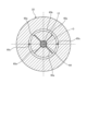
- FIG. 2 is a cross-sectional view taken along line II-II of FIG. 1 showing the first air passage.
- FIG. 3 is a cross-sectional view taken along line III-III of FIG. 1 showing the first bypass passage.
- FIG. 4 is a sectional view taken along line IV-IV of FIG. 1 showing the second air passage.
- FIG. 5 is a cross-sectional view taken along line VV of FIG. 1 showing the second air passage.
- FIG. 6 is a longitudinal sectional view showing the internal configuration of the electric compressor of the second embodiment.
- FIG. 7 is a longitudinal sectional view showing the internal configuration of the electric compressor of the third embodiment.
- FIG. 8 is a longitudinal sectional view showing the internal configuration of the electric compressor of the fourth embodiment.
- FIG. 1 is a longitudinal sectional view showing the internal configuration of the electric compressor of the first embodiment.
- the electric compressor 10 includes a housing 11, a rotating shaft 12, a low pressure wheel 13, a high pressure wheel 14, a low pressure side air bearing 15, a high pressure side air bearing 16, and a first air flow.
- a channel 17 , a second air flow path 18 and an air flow regulator 19 are provided.
- the housing 11 has a motor housing 21 , a low pressure side bearing housing 22 and a high pressure side bearing housing 23 .
- the motor housing 21 has a cylindrical shape and has an enlarged diameter end on one axial side (right side in FIG. 1).
- the low pressure side bearing housing 22 has a disk shape and is arranged on one side of the motor housing 21 in the axial direction.
- the low pressure side bearing housing 22 is detachably fastened to one axial end of the motor housing 21 with a plurality of bolts.
- the high pressure side bearing housing 23 has a disk shape and is arranged on the other side of the motor housing 21 in the axial direction.
- the high pressure side bearing housing 23 is detachably fastened to the other axial end of the motor housing 21 with a plurality of bolts.
- the cylindrical motor housing 21 has one axial opening closed by the low pressure side bearing housing 22 and the other axial opening closed by the high pressure side bearing housing 23 . Therefore, the housing 11 has a hollow shape by fastening the low pressure side bearing housing 22 and the high pressure side bearing housing 23 to the motor housing 21 .
- a stator 31 is fixed to the inner periphery of the motor housing 21 .
- the stator 31 has a cylindrical shape.
- the stator 31 has a stator core 32 and stator coils 33 .
- the stator core 32 has a cylindrical shape and is fixed so that its outer peripheral surface is in close contact with the inner peripheral surface of the motor housing 21 .
- the stator coil 33 is wound around the stator iron core 32 and partly accommodated inside the stator iron core 32.
- the low voltage side coil end 33a and the high voltage side coil end 33b are arranged on one side and the other side of the stator core 32 in the axial direction. expose.
- the rotating shaft 12 is arranged inside the housing 11 .
- the rotary shaft 12 is arranged along an axis O that is concentric with the housing 11 and is rotatably supported by the housing 11 about the axis O.
- a rotor 34 is fixed to the outer peripheral portion of the rotating shaft 12 at an intermediate position in the axial direction.
- the rotor 34 has a rotor iron core (permanent magnet) 35 .
- the rotor core 35 has a cylindrical shape and is fixed to the outer peripheral surface of the rotating shaft 12 .
- the inner peripheral surface and the outer peripheral surface of the stator 31 and the rotor 34 face each other in the radial direction.
- a gap is provided between the inner peripheral surface and the outer peripheral surface of the stator 31 and the rotor 34 . Therefore, when a current flows through the stator coil 33 of the stator 31, the rotor 34 rotates due to the attraction and repulsion forces of the generated magnetic force, and the rotating shaft 12 outputs a rotating force.
- the rotating shaft 12 is rotatably supported by the housing 11 with a low pressure side air bearing 15 and a high pressure side air bearing 16 .
- the rotating shaft 12 is provided with a low-pressure side shaft portion 12 a on one side of the rotor 34 in the axial direction, and a high-pressure side shaft portion 12 b on the other side of the rotor 34 in the axial direction.
- a low-pressure side bearing sleeve 36 is attached to the low-pressure side shaft portion 12a so as to be able to rotate together
- a high-pressure side bearing sleeve 37 is attached to the high-pressure side shaft portion 12b so as to be able to rotate together.
- the low pressure side bearing sleeve 36 functions as a low pressure side shaft portion
- the high pressure side bearing sleeve 37 functions as a high pressure side shaft portion.
- the low pressure side bearing sleeve 36 and the high pressure side bearing sleeve 37 may be omitted, and the rotating shaft 12 may be directly supported by the low pressure side air bearing 15 and the high pressure side air bearing 16 .
- the low pressure side air bearing 15 is provided integrally with the low pressure side bearing housing 22 .
- the low-pressure side air bearing 15 has a cylindrical shape and extends from the inner surface of the low-pressure side bearing housing 22 toward the rotor 34 .
- the low-pressure side air bearing 15 is arranged outside a low-pressure side bearing sleeve 36 attached to the rotating shaft 12 .
- a low pressure side clearance is secured between the inner peripheral surface of the low pressure side air bearing 15 and the outer peripheral surface of the low pressure side bearing sleeve 36 .
- the high pressure side air bearing 16 is provided integrally with the high pressure side bearing housing 23 .
- the high-pressure side air bearing 16 has a cylindrical shape and extends from the inner surface of the high-pressure side bearing housing 23 toward the rotor 34 .
- the high pressure side air bearing 16 is arranged outside a high pressure side bearing sleeve 37 mounted on the rotary shaft 12 .
- a high pressure side gap is secured between the inner peripheral surface of the high pressure side air bearing 16 and the outer peripheral surface of the high pressure side bearing sleeve 37 .
- the low pressure compressor 41 is arranged on the low pressure side bearing housing 22 side, and the high pressure compressor 42 is arranged on the high pressure side bearing housing 23 side.
- the low pressure compressor 41 has a low pressure side housing 43 and a low pressure wheel 13 .
- High pressure compressor 42 has a high pressure side housing 44 and high pressure wheel 14 .
- the low pressure side housing 43 is fastened to the outer surface of the low pressure side bearing housing 22 with a plurality of bolts.
- the low pressure wheel 13 is arranged inside the low pressure side housing 43 .
- the low-pressure wheel 13 is fixed to one axial end of the rotary shaft 12 by a bolt 45 so as to be rotatable together.
- the low-pressure compressor 41 is provided with a suction port 46, a diffuser 47, a spiral scroll portion 48, and a discharge port (not shown) by a low-pressure side housing 43 and a low-pressure wheel 13.
- the high pressure side housing 44 is fastened to the outer surface of the high pressure side bearing housing 23 with a plurality of bolts.
- the high pressure wheel 14 is located inside the high pressure side housing 44 .
- the high-pressure wheel 14 is fixed to the other axial end of the rotating shaft 12 by a bolt 49 so as to be rotatable therewith.
- the high pressure compressor 42 is provided with a suction port 50, a diffuser 51, a spiral scroll portion 52, and a discharge port (not shown) by means of a high pressure side housing 44 and a high pressure wheel .
- the low-pressure compressor 41 and the high-pressure compressor 42 are connected by a connection flow path 53 at the discharge port (not shown) and the suction port 50 .
- the low-pressure compressor 41 When the low-pressure wheel 13 rotates, the low-pressure compressor 41 sucks external air from the suction port 46 and is accelerated by the centrifugal force of the low-pressure wheel 13. After the accelerated air is decelerated and pressurized by the diffuser 47, the scroll It flows through the portion 48 and is discharged from the outlet. Low-pressure air compressed by the low-pressure compressor 41 is supplied to the high-pressure compressor 42 through the connecting flow path 53 .
- the high-pressure compressor 42 When the high-pressure wheel 14 rotates, the high-pressure compressor 42 sucks external air from the suction port 50 and is accelerated by the centrifugal force of the high-pressure wheel 14. After the accelerated air is decelerated and pressurized by the diffuser 51, the scroll rotates. It flows through the portion 52 and is discharged from the outlet.
- FIG. 2 is a sectional view taken along line II-II in FIG. 1 showing the first air passage
- FIG. 3 is a sectional view taken along line III-III in FIG. 1 showing the first bypass passage.
- the first air flow path 17 supplies compressed air from the housing 11 to the low pressure side air bearing 15 .
- a plurality of first air flow paths 17 may be provided.
- the first air flow path 17 is provided along the radial direction of the rotating shaft 12 in the housing 11 .
- the low pressure side bearing housing 22 is provided with one (or a plurality of) first air flow paths 17 along the radial direction.
- the first air flow path 17 is provided with an air intake port 61 at one end on the radially outer side.
- the air intake port 61 is connected to a bleed flow path 62 branched from the connection flow path 53 .
- a part of the low-pressure air (compressed air) discharged from the low-pressure compressor 41 is extracted by the extraction passage 62 and supplied to the air intake port 61 in the first air passage 17 .
- the air intake port 61 may be connected to a bleed passage through which the high-pressure air (compressed air) discharged from the high-pressure compressor 42 is bleed.
- the low-pressure side bearing housing 22 is provided with a low-pressure side space 63 around the axis O. As shown in FIG. The other end on the radially inner side of the first air flow path 17 communicates with the low pressure side space 63 .
- a thrust disc 64 that constitutes a thrust bearing is fixed to the rotating shaft 12 .
- a thrust disk 64 is fixed between the low pressure side bearing sleeve 36 and the low pressure wheel 13 on the rotary shaft 12 .
- the thrust disk 64 rotates integrally with the rotating shaft 12 .
- the thrust disk 64 is arranged in the low pressure side space 63 .
- the low-pressure side bearing housing 22 has a low-pressure side annular passage 63a, a one side annular passage 63b, and a second side annular passage 63c formed by arranging the thrust disk 64 in the low pressure side space 63. be.
- the low pressure side annular passage 63a, the one side annular passage 63b and the other side annular passage 63c are continuous in the circumferential direction.
- the low-pressure side annular passage 63 a is provided on the outer peripheral side of the thrust disk 64 in the low-pressure side space portion 63 .
- the one-surface-side annular passage 63 b is provided on one surface side (low-pressure wheel 13 side) of the thrust disk 64 in the low-pressure-side space portion 63 .
- the other surface side annular passage 63 c is provided on the other surface side (low pressure side bearing sleeve 36 side) of the thrust disk 64 in the low pressure side space portion 63 .
- the other surface side annular passage 63 c communicates with the low pressure gap between the inner peripheral surface of the low pressure side air bearing 15 and the outer peripheral surface of the low pressure side bearing sleeve 36 .
- the low-pressure side bearing housing 22 has a wear-resistant coating layer applied to the surfaces facing the one-side annular passage 63b and the other-side annular passage 63c, and cooling is required to protect the wear-resistant coating layer. is necessary.
- the low-pressure air (hereinafter referred to as compressed air) extracted from the connection flow path 53 is sent from the extraction flow path 62 to the air intake port 61, flows radially inward through the first air flow path 17, and reaches the low pressure. It is supplied to the side annular channel 63a (the low-pressure side space 63). At this time, the compressed air in the low pressure side annular passage 63a is supplied to the one side annular passage 63b and the other side annular passage 63c. High-pressure air acts on the thrust disk 64 on one side and the other side, so that the rotating shaft 12 integrated with the thrust disk 64 is supported at a predetermined position in the axial direction. Also, in the low-pressure side bearing housing 22, the wear-resistant coating layer applied to the surface facing the one-side annular passage 63b and the other-side annular passage 63c is cooled by compressed air.
- the compressed air in the low pressure side annular passage 63a is supplied to the low pressure side air bearing 15 through the other side annular passage 63c. That is, the compressed air is supplied to the low-pressure gap between the inner peripheral surface of the low-pressure side air bearing 15 and the outer peripheral surface of the low-pressure side bearing sleeve 36, thereby supporting the rotating shaft 12 at a predetermined position in the radial direction. After that, the compressed air supplied to the low pressure side air bearing 15 flows into the gap between the stator 31 and the rotor 34 to cool the stator core 32 and stator coil 33 of the stator 31 . The compressed air that has cooled the stator 31 is discharged to the outside from an air discharge port 95 provided in the housing 11 .
- the low-pressure side bearing housing 22 is provided with a first bypass flow path 65 .
- the first bypass flow path 65 opens toward the stator coil 33 in the stator 31 through the one-side annular passage 63b.
- the first bypass channel 65 has a radial channel 65a, an annular channel 65b, and an axial channel 65c.
- One end of the radial flow passage 65a communicates with the one-side annular passage 63b, and the other end communicates with the annular passage 65b.
- a plurality of radial flow paths 65a are provided at intervals in the circumferential direction of the low pressure side bearing housing 22 .
- One end of the axial flow path 65 c communicates with the annular flow path 65 b and the other end opens to the inner surface of the low-pressure side bearing housing 22 .
- a plurality of axial flow paths 65 c are provided at intervals in the circumferential direction of the low pressure side bearing housing 22 .
- the compressed air in the one-side annular passage 63b flows through the radial flow path 65a, the annular flow path 65b, and the axial flow path 65c of the first bypass flow path 65, and is discharged to the inner surface side of the low pressure side bearing housing 22. This cools the stator coil 33 facing the inner surface of the low pressure side bearing housing 22 .
- ⁇ Second air flow path> 4 is a sectional view taken along line IV-IV in FIG. 1 showing the second air passage
- FIG. 5 is a sectional view taken along line VV in FIG. 1 showing the second air passage.
- the second air flow path 18 is branched from the first air flow path 17 and supplies compressed air to the high pressure side air bearing 16. As shown in FIG. Although only one second air flow path 18 is provided in the housing 11, a plurality of second air flow paths 18 may be provided.
- the second air flow path 18 has an axial air flow path 71 and a radial air flow path 72 .
- the axial air flow path 71 is branched from the first air flow path 17 and provided along the axial direction of the rotating shaft 12 in the housing 11 .
- the radial air flow path 72 communicates with the axial air flow path 71 and is provided along the radial direction of the rotating shaft 12 in the housing 11 .
- the motor housing 21 is provided with one axial air flow path 71 along the axial direction.
- One end of the axial air flow path 71 communicates with a branch portion 66 provided in the first air flow path 17 .
- the high pressure side bearing housing 23 is provided with one (or a plurality of) radial air flow paths 72 along the radial direction.
- One radially outer end of the radial air flow path 72 communicates with the other end of the axial air flow path 71 .
- the high-pressure side bearing housing 23 is provided with a high-pressure side annular flow path 73 around the axis O. As shown in FIG.
- the high pressure side annular passage 73 is provided outside the end of the high pressure side bearing sleeve 37 on the high pressure wheel 14 side.
- the other radially inner end of the radial air flow path 72 communicates with the high-pressure side annular flow path 73 .
- the high pressure side annular passage 73 communicates with the high pressure gap between the inner peripheral surface of the high pressure side air bearing 16 and the outer peripheral surface of the high pressure side bearing sleeve 37 .
- the compressed air branched from the first air flow path 17 flows axially through the axial air flow path 71 of the second air flow path 18, and then flows radially inward through the radial air flow path 72. flow is fed to the high pressure side annular passage 73 . Compressed air in the high pressure side annular passage 73 is supplied to the high pressure side air bearing 16 . That is, the compressed air is supplied to the high-pressure gap between the inner peripheral surface of the high-pressure side air bearing 16 and the outer peripheral surface of the high-pressure side bearing sleeve 37, thereby supporting the rotating shaft 12 at a predetermined position in the radial direction.
- the compressed air supplied to the high pressure side air bearing 16 flows into the gap between the stator 31 and the rotor 34 to cool the stator core 32 and stator coil 33 of the stator 31 .
- the compressed air that has cooled the stator 31 is discharged to the outside through an air discharge port 95 provided in the housing 11 .
- Air flow control device 19 adjusts the flow rate of compressed air flowing through the first air flow path 17 and the second air flow path 18 .
- the air flow rate adjusting device 19 is provided in the second air flow path 18 .
- the air flow rate adjusting device 19 has a plurality of air flow rate adjusting members 81 with different flow path areas.
- the air flow rate adjusting member 81 is provided detachably with respect to the housing 11 .
- the air flow rate adjusting member 81 is, for example, a pipe in which a linear flow path 82 having a circular cross section is formed.
- a plurality of types of air flow rate adjusting members 81 are prepared in which the flow area of the straight flow path 82 is equal to or less than the flow area of the axial air flow path 71 in the second air flow path 18 .
- the air flow rate adjusting member 81 may be a channel having constricted portions with different channel areas.
- the motor housing 21 is provided with a first housing recess 83 communicating with one end of the axial air flow path 71 on one end side in the axial direction. Further, the low-pressure side bearing housing 22 is provided with a second housing recess 84 communicating with the branch portion 66 of the first air flow path 17 on the inner surface side.
- the air flow rate adjusting member 81 is housed in the first air flow path 17 and the second housing recess 84 when the motor housing 21 is assembled to the low pressure side bearing housing 22 .
- the air flow rate adjusting member 81 having the linear flow path 82 with the optimum flow area is selected and assembled.
- Compressed air taken into the housing 11 is supplied to the low pressure side of the stator 31 through the low pressure side air bearing 15 by the first air flow path 17 to cool the low pressure side of the stator coil 33 .
- Compressed air is supplied to the high pressure side of the stator 31 through the high pressure side air bearing 16 by the second air flow path 18 branched from the first air flow path 17 to cool the high pressure side of the stator coil 33. .
- the inner surfaces of the low pressure side air bearing 15 and the high pressure side air bearing 16 are coated with a wear-resistant coating, and it is necessary to cool the inner surface temperature of the low pressure side air bearing 15 and the high pressure side air bearing 16 to below the heat resistant temperature of the coating. .
- the air flow rate adjusting device 19 adjusts the flow rate of compressed air so that the inner surface temperatures of the low pressure side air bearing 15 and the high pressure side air bearing 16 are equal to or lower than the heat resistance temperature.
- the air flow rate adjusting device 19 adjusts the flow rate of compressed air so that the temperature of the low-pressure side coil end 33a and the temperature of the high-pressure side coil end 33b of the stator coil 33 are within the proper temperature ranges.
- the air flow rate adjustment device 19 controls the inner surface temperature of the low-pressure side air bearing 15 and the inner surface temperature of the high-pressure side air bearing 16 to be below the heat resistance temperature, and the temperature of the low-pressure side coil end 33 a of the stator coil 33 . and the temperature of the high pressure side coil end 33b is adjusted to be within the proper temperature range.
- the temperature of the high pressure side bearing sleeve 37 and the temperature of the high pressure side coil end 33b tend to be higher than the temperatures of the low pressure side bearing sleeve 36 and the low pressure side coil end 33a.
- the air flow rate adjusting device 19 selects the air flow rate adjusting member 81 so that the amount of compressed air flowing through the second air flow path 18 is greater than the amount of compressed air flowing through the first air flow path 17, thereby increasing the amount of compressed air. adjust the flow rate of In this case, in consideration of the balance between the inner surface temperature of the low pressure side air bearing 15 and the inner surface temperature of the high pressure side air bearing 16 and the balance of the temperature of the low pressure side coil end 33a and the high pressure side coil end 33b of the stator coil 33, the compressed air is adjust the flow rate of
- the compressed air is supplied to the low-pressure side annular passage 63a (low-pressure side space 63) through the first air passage 17, and is supplied to the low-pressure side air bearing 15 through the other surface side annular passage 63c.
- the compressed air cools the low pressure side air bearing 15 and the low pressure side bearing sleeve 36 .
- the compressed air branched from the first air flow path 17 passes through the axial air flow path 71 and the radial air flow path 72 of the second air flow path 18 and is supplied to the high pressure side annular flow path 73. It is supplied to the air bearing 16 .
- the high pressure side air bearing 16 and the high pressure side bearing sleeve 37 are cooled by the compressed air.
- the compressed air then flows through the gap between the stator 31 and the rotor 34 to cool the stator 31 .
- the flow rate of the compressed air flowing through the second air flow path 18 is adjusted by the air flow rate adjusting device 19 so that the flow rate of the compressed air flowing through the first air flow path 17 is also adjusted. Therefore, the low-pressure side air bearing 15 and the low-pressure side bearing sleeve 36, and the high-pressure side air bearing 16 and the high-pressure side bearing sleeve 37 are cooled to an appropriate temperature. Also, the high-voltage side coil end 33b and the low-voltage side coil end 33a of the stator coil 33 are cooled to an appropriate temperature.
- FIG. 6 is a longitudinal sectional view showing the internal configuration of the electric compressor of the second embodiment.
- Members having the same functions as those of the above-described first embodiment are denoted by the same reference numerals, and detailed description thereof will be omitted.
- the electric compressor 10A includes a housing 11, a rotating shaft 12, a low pressure wheel 13, a high pressure wheel 14, a low pressure side air bearing 15, a high pressure side air bearing 16, a first air flow A channel 17, a second air flow path 18, and an air flow rate adjusting device 19 are provided, and the basic configuration is the same as that of the first embodiment.
- the low pressure side bearing housing 22 is provided with a first bypass flow path 65 and a second bypass flow path 91 .
- the first bypass flow path 65 opens to the inner surface of the low pressure side bearing housing 22 toward the stator coil 33 in the stator 31 through the one side annular passage 63b.
- the second bypass flow path 91 opens to the inner surface of the low pressure side bearing housing 22 toward the stator coil 33 of the stator 31 through the other side annular passage 63c.
- the first bypass flow path 65 opens toward the coil end on the radially intermediate side of the stator coil 33
- the second bypass flow path 91 opens on the radially inner peripheral side of the stator coil 33 . Open toward the coil end.
- a plurality of second bypass flow paths 91 are provided at intervals in the circumferential direction of the low pressure side bearing housing 22 .
- the compressed air in the low pressure side annular passage 63a is discharged toward the stator coil 33 through the first bypass passage 65 from the one side annular passage 63b.
- the compressed air in the low-pressure side annular passage 63a is supplied from the other surface side annular passage 63c to the low-pressure gap between the low-pressure side air bearing 15 and the low-pressure side bearing sleeve 36, and passes through the second bypass passage 91. It is discharged toward the stator coil 33 . That is, with respect to the thrust disc 64, the compressed air in the one-side annular passage 63b is discharged toward the stator coil 33 through the first bypass passage 65, and the compressed air in the other-side annular passage 63c is discharged as the second bypass flow.
- the compressed air in the other side annular passage 63 c is supplied to the low pressure gap between the low pressure side air bearing 15 and the low pressure side bearing sleeve 36 . Therefore, it is necessary to consider the number and flow area of the second bypass passages 91 so that the flow rate of compressed air required by the low-pressure side air bearing 15 and the low-pressure side bearing sleeve 36 does not decrease.
- FIG. 7 is a longitudinal sectional view showing the internal configuration of the electric compressor of the third embodiment.
- Members having the same functions as those of the above-described first embodiment are denoted by the same reference numerals, and detailed description thereof will be omitted.
- the electric compressor 10B includes a housing 11, a rotating shaft 12, a low pressure wheel 13, a high pressure wheel 14, a low pressure side air bearing 15, a high pressure side air bearing 16, a first air flow A channel 17, a second air flow path 18, and an air flow rate adjusting device 19 are provided, and the basic configuration is the same as that of the first embodiment.
- the high pressure side bearing housing 23 is provided with a third bypass flow path 92 .
- the third bypass channel 92 branches from the second air channel 18 and opens toward the stator 31 .
- One end of the third bypass flow path 92 communicates with the connecting portion between the axial air flow path 71 and the radial air flow path 72 in the second air flow path 18 .
- One end of the third bypass channel 92 may be connected to at least one of the axial air channel 71 and the radial air channel 72 .
- the other end of the third bypass flow path 92 opens to the inner surface of the high pressure side bearing housing 23 toward the stator coil 33 in the stator 31 .
- the third bypass flow path 92 opens toward the coil end on the radially outer peripheral side of the stator coil 33 .
- a plurality of third bypass flow paths 92 are provided at intervals in the circumferential direction of the high pressure side bearing housing 23 .
- the compressed air branched to the second air flow path 18 passes through the axial air flow path 71 and the radial air flow path 72, is supplied to the high pressure side annular flow path 73, and is supplied to the high pressure side air bearing 16. .
- the compressed air branched to the second air flow path 18 branches from the axial air flow path 71 to the third bypass flow path 92 and is directed to the high-pressure side coil end 33b of the stator coil 33 through the third bypass flow path 92. to cool the high-pressure side coil end 33b.
- the electric compressor 10B compresses low-pressure air into high-pressure air using the high-pressure compressor 42, the temperature of the high-pressure side coil end 33b of the stator coil 33 tends to rise. Therefore, by guiding the compressed air to the high-pressure side coil end 33b of the stator coil 33 through the third bypass flow path 92, the high-temperature coil end is positively cooled and the temperature rise is suppressed.
- the low-pressure side bearing housing 22 is provided with the first bypass flow path 65, so that the compressed air is supplied from the first bypass flow path 65 to the low-pressure side coil end 33a of the stator coil 33 for cooling. are doing. Therefore, the number and flow area of the third bypass flow path 92 are set so that the temperature of the low-voltage side coil end 33a of the stator coil 33 and the temperature of the high-voltage side coil end 33b are appropriate.
- FIG. 8 is a longitudinal sectional view showing the internal configuration of the electric compressor of the fourth embodiment.
- Members having the same functions as those of the above-described first embodiment are denoted by the same reference numerals, and detailed description thereof will be omitted.
- the electric compressor 10C includes a housing 11, a rotating shaft 12, a low pressure wheel 13, a high pressure wheel 14, a low pressure side air bearing 15, a high pressure side air bearing 16, a first air flow A channel 17, a second air flow path 18, and an air flow rate adjusting device 19 are provided, and the basic configuration is the same as that of the first embodiment.
- the electric compressor 10C has a third air flow path 93.
- the third air flow path 93 supplies compressed air to the gap between the stator 31 and the rotor 34 .
- the third air flow path 93 has an air supply port 94 and an air discharge port 95 .
- the motor housing 21 is provided with an air supply port 94 on the high pressure side bearing housing 23 side.
- the motor housing 21 is provided with an air discharge port 95 on the low pressure side bearing housing 22 side.
- the air supply port 94 is connected to a bleed flow path 96 branched from the connection flow path 53 .
- the third air flow path 93 discharges the compressed air from the air supply port 94 through the high pressure side coil end 33b of the stator coil 33, the gap between the stator iron core 32 and the rotor 34, and the low pressure side coil end 33a from the air discharge port 95.
- flow path One third air flow path 93 air supply port 94, air discharge port 95
- the compressed air taken into the housing 11 through the air intake port 61 is supplied to the low-pressure side air bearing 15 and the thrust disk 64 through the first air flow path 17, and is supplied to the high-pressure side air through the second air flow path 18.
- the compressed air taken into the housing 11 from the air supply port 94 is supplied to the stator 31 and the rotor 34 to mainly cool the stator 31 and the rotor 34 .
- the compressed air that has cooled the low-pressure side air bearing 15 and the high-pressure side air bearing 16 and the compressed air that has cooled the stator 31 and the rotor 34 join together and are discharged from the air discharge port 95 to the outside.
- the compressed air that has flowed through the first air flow path 17 and the second air flow path 18 is also discharged from the air discharge port 95 .
- the electric compressor according to the first aspect includes a housing 11 having a cylindrical stator 31, a rotating shaft 12 having a rotor 34 arranged inside the housing 11 and facing the stator 31, and a rotating shaft
- a housing 11 rotatably supports a low-pressure wheel 13 fixed to one axial direction of the rotary shaft 12, a high-pressure wheel 14 fixed to the other axial direction of the rotary shaft 12, and a low-pressure side shaft portion 12a of the rotary shaft 12.
- a low-pressure side air bearing 15 a low-pressure side air bearing 15; a high-pressure side air bearing 16 that rotatably supports the high-pressure side shaft portion 12b of the rotating shaft 12 in the housing 11; a first air flow path 17 that supplies to either one; a second air flow path 18 that branches from the first air flow path 17 and supplies to the other of the low-pressure side air bearing 15 and the high-pressure side air bearing 16; and an air flow rate adjusting device 19 that adjusts the flow rates of the compressed air flowing through the first air flow path 17 and the second air flow path 18 .
- the compressed air is supplied to the low-pressure side air bearing 15 through the first air flow path 17 and is supplied to the low-pressure side air bearing 15 through the second air flow path 18 branching off from the first air flow path 17 to produce high pressure air. It is supplied to the side air bearing 16 . Therefore, an annular flow path or the like for temporarily storing compressed air in the housing 11 is not required, and the structure can be simplified. The air bearing 16 can function properly.
- the compressed air has its flow rate adjusted by the air flow rate adjusting device 19 to flow through the first air flow path 17 and the second air flow path 18 .
- an appropriate amount of compressed air can be supplied to the low-pressure side air bearing 15 and the high-pressure side air bearing 16, and the low-pressure side air bearing 15 and the high-pressure side air bearing 16 can be properly functioned. 15 and the high pressure side air bearing 16 can be properly cooled.
- the first air flow path 17 is provided along the radial direction of the rotating shaft 12 in the housing 11, and the second air flow path 18 is branched from the first air flow path 17.
- An axial air flow path 71 provided along the axial direction of the rotating shaft 12 in the housing 11, and a radial air flow provided along the radial direction of the rotating shaft 12 in the housing 11 in communication with the axial air flow path 71.
- a path 72 is provided.
- the electric compressor according to the fourth aspect is provided with the air flow rate adjusting device 19 in at least one of the first air flow path 17 and the second air flow path 18 . Accordingly, by adjusting the flow rate of one of the first air flow path 17 and the second air flow path 18 with the air flow rate adjusting device 19, the flow rate of the other can also be adjusted, and the structure can be simplified. .
- an air flow rate adjusting member 81 having a predetermined flow passage area is provided, and the air flow rate adjusting member 81 is detachably attached to the housing 11. do. Accordingly, by mounting the air flow rate adjusting member 81 having the optimum flow path area to the housing 11 according to the configuration of the electric compressors 10, 10A, 10B, and 10C, the first air flow path 17 and the second air flow The flow rate of channel 18 can be adjusted appropriately.
- the electric compressor according to the sixth aspect includes a thrust disk 64 fixed to the low-pressure wheel 13 side or the high-pressure wheel 14 side of the rotary shaft 12, and one of the thrust disks 64 branched from the first air flow path 17.
- a second bypass flow path 91 is provided.
- the second air flow path 18 supplies compressed air to the high-pressure side air bearing 16, and branches from the second air flow path 18 and opens toward the stator 31.
- a third bypass flow path 92 is provided. Accordingly, by positively supplying the compressed air from the second air flow path 18 to the high-pressure side coil end 33b of the stator coil 33, the high-pressure side coil end 33b, which tends to reach a relatively high temperature, can be appropriately cooled. can.
- the electric compressor according to the eighth aspect supplies compressed air from the housing 11 to the gap between the stator 31 and the rotor 34 separately from the first air flow path 17 and the second air flow path 18 .
- 3 air flow channels 93 are provided; Thereby, the first air flow path 17 and the second air flow path 18 supply the compressed air to the low pressure side air bearing 15 and the high pressure side air bearing 16 to cool them.
- the third air flow path 93 supplies and cools the stator 31 and the rotor 34 . Therefore, the cooling performance can be improved by cooling the low pressure side air bearing 15 and the high pressure side air bearing 16, the stator 31 and the rotor 34 with dedicated compressed air.
- the first air flow path 17 is provided in the low pressure side bearing housing 22 and the second air flow path 18 is provided in the motor housing 21 and the high pressure side bearing housing 23, but the configuration is limited to this. not a thing
- the first air flow path 17 may be provided in the high pressure side bearing housing 23 and the second air flow path 18 may be provided in the motor housing 21 and the low pressure side bearing housing 22 .
Abstract
電動圧縮機において、円筒形状をなす固定子を有するハウジングと、ハウジングの内部に配置されて固定子に対向する回転子を有する回転軸と、回転軸における軸方向の一方に固定される低圧ホイールと、回転軸における軸方向の他方に固定される高圧ホイールと、回転軸における低圧側軸部をハウジングに回転自在に支持する低圧側空気軸受と、回転軸における高圧側軸部をハウジングに回転自在に支持する高圧側空気軸受と、圧縮空気をハウジングから低圧側空気軸受と高圧側空気軸受のいずれか一方に供給する第1空気流路と、第1空気流路から分岐して低圧側空気軸受と高圧側空気軸受のいずれか他方に供給する第2空気流路と、第1空気流路および第2空気流路を流れる圧縮空気の流量を調整する空気流量調整装置と、を備える。
Description
本開示は、2段圧縮式の電動圧縮機に関するものである。
例えば、燃料電池は、高い圧力の空気を必要とすることから、2段圧縮式の電動圧縮機が適用される。2段圧縮式の電動圧縮機は、ハウジングに回転軸が回転自在に支持され、回転軸における軸方向の一方に低圧ホイールが設けられ、軸方向の他方に高圧ホイールが設けられて構成される。回転軸は、ハウジングに空気軸受により回転自在に支持される。空気軸受は、低圧ホイール側に配置される低圧側空気軸受と、高圧ホイール側に配置される高圧側空気軸受とを有する。低圧ホイールまたは高圧ホイールにより圧縮された圧縮空気は、一部が抽気されて低圧側空気軸受および高圧側空気軸受に供給される。このような空気軸受を備える電動圧縮機として、例えば、下記特許文献1に記載されたものがある。
従来の電動圧縮機は、低圧の圧縮空気の一部を低圧側空気軸受に供給し、高圧の圧縮空気の一部を高圧側空気軸受に供給している。この場合、ハウジングにおける低圧ホイール側と高圧ホイールに側にそれぞれ周方向に沿う円環流路を設けている。そして、圧縮空気の一部を円環流路に貯留し、円環流路に貯留した圧縮空気を空気軸受に供給している。このような構成では、円環流路が所定の容積を有する空間部であることから、圧縮空気が円環流路に貯留されたときに圧力損失が増大する。すると、圧縮空気を供給する空気軸受が適切に機能しないおそれがある。
本開示は、上述した課題を解決するものであり、圧縮空気の圧力損失を低減することで空気軸受を適切に機能させることができる電動圧縮機を提供することを目的とする。
上記の目的を達成するための本開示の電動圧縮機は、円筒形状をなす固定子を有するハウジングと、前記ハウジングの内部に配置されて前記固定子に対向する回転子を有する回転軸と、前記回転軸における軸方向の一方に固定される低圧ホイールと、前記回転軸における軸方向の他方に固定される高圧ホイールと、前記回転軸における低圧側軸部を前記ハウジングに回転自在に支持する低圧側空気軸受と、前記回転軸における高圧側軸部を前記ハウジングに回転自在に支持する高圧側空気軸受と、圧縮空気を前記ハウジングから前記低圧側空気軸受と前記高圧側空気軸受のいずれか一方に供給する第1空気流路と、前記第1空気流路から分岐して前記低圧側空気軸受と前記高圧側空気軸受のいずれか他方に供給する第2空気流路と、前記第1空気流路および前記第2空気流路を流れる圧縮空気の流量を調整する空気流量調整装置と、を備える。
本開示の電動圧縮機によれば、圧縮空気の圧力損失を低減することで空気軸受を適切に機能させることができる。
以下に図面を参照して、本開示の好適な実施形態を詳細に説明する。なお、この実施形態により本開示が限定されるものではなく、また、実施形態が複数ある場合には、各実施形態を組み合わせて構成するものも含むものである。また、実施形態における構成要素には、当業者が容易に想定できるもの、実質的に同一のもの、いわゆる均等の範囲のものが含まれる。
[第1実施形態]
<電動圧縮機の構成>
図1は、第1実施形態の電動圧縮機の内部構成を表す縦断面図である。
<電動圧縮機の構成>
図1は、第1実施形態の電動圧縮機の内部構成を表す縦断面図である。
図1に示すように、電動圧縮機10は、ハウジング11と、回転軸12と、低圧ホイール13と、高圧ホイール14と、低圧側空気軸受15と、高圧側空気軸受16と、第1空気流路17と、第2空気流路18と、空気流量調整装置19とを備える。
ハウジング11は、モータハウジング21と、低圧側軸受ハウジング22と、高圧側軸受ハウジング23とを有する。モータハウジング21は、円筒形状をなし、軸方向の一方側(図1の右方側)の端部が拡径している。低圧側軸受ハウジング22は、円盤形状をなし、モータハウジング21における軸方向の一方側に配置される。低圧側軸受ハウジング22は、モータハウジング21における軸方向の一方側の端部に複数のボルトにより着脱自在に締結される。高圧側軸受ハウジング23は、円盤形状をなし、モータハウジング21における軸方向の他方側に配置される。高圧側軸受ハウジング23は、モータハウジング21における軸方向の他方側の端部に複数のボルトにより着脱自在に締結される。
円筒形状をなすモータハウジング21は、軸方向の一方の開口が低圧側軸受ハウジング22により閉塞され、軸方向の他方の開口が高圧側軸受ハウジング23により閉塞される。そのため、ハウジング11は、モータハウジング21に低圧側軸受ハウジング22と高圧側軸受ハウジング23が締結されることで、中空形状をなす。
モータハウジング21は、内周部に固定子31が固定される。固定子31は、円筒形状をなす。固定子31は、ステータ鉄芯32と、ステータコイル33とを有する。ステータ鉄芯32は、円筒形状をなし、外周面がモータハウジング21の内周面に密着するように固定される。ステータコイル33は、ステータ鉄芯32に巻き付けられ、一部がステータ鉄芯32の内部に収納され、低圧側コイルエンド33aおよび高圧側コイルエンド33bがステータ鉄芯32の軸方向の一方および他方に露出する。
回転軸12は、ハウジング11の内部に配置される。回転軸12は、ハウジング11と同心の軸心Oに沿って配置され、軸心Oを中心にハウジング11に回転自在に支持される。回転軸12は、軸方向における中間位置の外周部に回転子34が固定される。回転子34は、ロータ鉄芯(永久磁石)35を有する。ロータ鉄芯35は、円筒形状をなし、回転軸12の外周面に固定される。
固定子31と回転子34は、内周面と外周面が径方向に対向する。固定子31と回転子34は、内周面と外周面との間に隙間が設けられる。そのため、固定子31のステータコイル33に電流が流れると、発生する磁力の吸引力および反発力により回転子34が回転し、回転軸12が回転力を出力する。
回転軸12は、ハウジング11に低圧側空気軸受15と高圧側空気軸受16により回転自在に支持される。回転軸12は、回転子34より軸方向の一方側に低圧側軸部12aが設けられ、回転子34より軸方向の他方側に高圧側軸部12bが設けられる。回転軸12は、低圧側軸部12aに低圧側軸受スリーブ36が一体回転可能に装着され、高圧側軸部12bに高圧側軸受スリーブ37が一体回転可能に装着される。低圧側軸受スリーブ36は、低圧側軸部として機能し、高圧側軸受スリーブ37は、高圧側軸部として機能する。なお、低圧側軸受スリーブ36と高圧側軸受スリーブ37をなくしてもよく、低圧側空気軸受15および高圧側空気軸受16により回転軸12を直接支持してもよい。
低圧側空気軸受15は、低圧側軸受ハウジング22に一体に設けられる。低圧側空気軸受15は、円筒形状をなし、低圧側軸受ハウジング22の内面から回転子34側に延出して形成される。低圧側空気軸受15は、回転軸12に装着された低圧側軸受スリーブ36の外方に配置される。低圧側空気軸受15の内周面と低圧側軸受スリーブ36の外周面との間に低圧側隙間が確保される。
高圧側空気軸受16は、高圧側軸受ハウジング23に一体に設けられる。高圧側空気軸受16は、円筒形状をなし、高圧側軸受ハウジング23の内面から回転子34側に延出して形成される。高圧側空気軸受16は、回転軸12に装着された高圧側軸受スリーブ37の外方に配置される。高圧側空気軸受16の内周面と高圧側軸受スリーブ37の外周面との間に高圧側隙間が確保される。
ハウジング11は、低圧側軸受ハウジング22側に低圧圧縮機41が配置され、高圧側軸受ハウジング23側に高圧圧縮機42が配置される。低圧圧縮機41は、低圧側ハウジング43と、低圧ホイール13とを有する。高圧圧縮機42は、高圧側ハウジング44と、高圧ホイール14とを有する。
低圧側ハウジング43は、低圧側軸受ハウジング22の外面に複数のボルトにより締結される。低圧ホイール13は、低圧側ハウジング43の内部に配置される。低圧ホイール13は、回転軸12における軸方向の一端部にボルト45により一体回転可能に固定される。低圧圧縮機41は、低圧側ハウジング43と低圧ホイール13により、吸入口46、ディフューザ47、渦巻き形状をなすスクロール部48、吐出口(図示略)が設けられる。
高圧側ハウジング44は、高圧側軸受ハウジング23の外面に複数のボルトにより締結される。高圧ホイール14は、高圧側ハウジング44の内部に配置される。高圧ホイール14は、回転軸12における軸方向の他端部にボルト49により一体回転可能に固定される。高圧圧縮機42は、高圧側ハウジング44と高圧ホイール14により、吸入口50、ディフューザ51、渦巻き形状をなすスクロール部52、吐出口(図示略)が設けられる。
また、低圧圧縮機41と高圧圧縮機42は、吐出口(図示略)と吸入口50とが連結流路53により連結される。
低圧圧縮機41は、低圧ホイール13が回転すると、外部の空気が吸入口46から吸入されて低圧ホイール13の遠心力により加速され、加速された空気がディフューザ47により減速加圧された後、スクロール部48を流れ、吐出口から排出される。低圧圧縮機41により圧縮された低圧空気は、連結流路53により高圧圧縮機42に送給される。高圧圧縮機42は、高圧ホイール14が回転すると、外部の空気が吸入口50から吸入されて高圧ホイール14の遠心力により加速され、加速された空気がディフューザ51により減速加圧された後、スクロール部52を流れ、吐出口から排出される。
<第1空気流路>
図2は、第1空気通路を表す図1のII-II断面図、図3は、第1バイパス通路を表す図1のIII-III断面図である。
図2は、第1空気通路を表す図1のII-II断面図、図3は、第1バイパス通路を表す図1のIII-III断面図である。
図1および図2に示すように、第1空気流路17は、圧縮空気をハウジング11から低圧側空気軸受15に供給する。第1空気流路17は、ハウジング11に1個だけ設けられるが、複数設けてもよい。第1空気流路17は、ハウジング11における回転軸12の径方向に沿って設けられる。
すなわち、低圧側軸受ハウジング22は、径方向に沿って1個(または、複数)の第1空気流路17が設けられる。第1空気流路17は、径方向の外方側の一端に空気取込口61が設けられる。空気取込口61は、連結流路53から分岐した抽気流路62が連結される。第1空気流路17は、低圧圧縮機41から排出された低圧空気(圧縮空気)の一部が抽気流路62により抽気されて空気取込口61に供給される。なお、空気取込口61は、高圧圧縮機42から排出された高圧空気(圧縮空気)を抽気した抽気流路が連結されてもよい。低圧側軸受ハウジング22は、軸心Oの外周辺に低圧側空間部63が設けられる。第1空気流路17は、径方向の内方側の他端が低圧側空間部63に連通する。
回転軸12は、スラスト軸受を構成するスラスト円板64が固定される。スラスト円板64は、回転軸12における低圧側軸受スリーブ36と低圧ホイール13との間に固定される。スラスト円板64は、回転軸12と一体に回転する。スラスト円板64は、低圧側空間部63に配置される。低圧側軸受ハウジング22は、スラスト円板64が低圧側空間部63に配置されることで、低圧側環状流路63aと、一方面側環状通路63bと、他方面側環状通路63cとが形成される。低圧側環状流路63aと一方面側環状通路63bと他方面側環状通路63cは、周方向に連続する。低圧側環状流路63aは、低圧側空間部63におけるスラスト円板64の外周側に設けられる。一方面側環状通路63bは、低圧側空間部63におけるスラスト円板64の一方面側(低圧ホイール13側)に設けられる。他方面側環状通路63cは、低圧側空間部63におけるスラスト円板64の他方面側(低圧側軸受スリーブ36側)に設けられる。他方面側環状通路63cは、低圧側空気軸受15の内周面と低圧側軸受スリーブ36の外周面との低圧隙間に連通する。そして、低圧側軸受ハウジング22は、一方面側環状通路63bおよび他方面側環状通路63cに対向する面に耐摩耗性コーティング層が施されており、耐摩耗性コーティング層を保護するために冷却が必要である。
そのため、連結流路53から抽気した低圧空気(以下、圧縮空気)は、抽気流路62から空気取込口61に送られ、第1空気流路17を径方向の内方側に流れ、低圧側環状流路63a(低圧側空間部63)に供給される。このとき、低圧側環状流路63aの圧縮空気は、一方面側環状通路63bと他方面側環状通路63cに供給される。スラスト円板64は、一方面側と他方面側に高圧空気が作用することで、スラスト円板64と一体の回転軸12は、軸方向の所定の位置に支持される。また、低圧側軸受ハウジング22は、一方面側環状通路63bおよび他方面側環状通路63cに対向する面に施された耐摩耗性コーティング層が圧縮空気により冷却される。
低圧側環状流路63aの圧縮空気は、他方面側環状通路63cを通って低圧側空気軸受15に供給される。すなわち、圧縮空気は、低圧側空気軸受15の内周面と低圧側軸受スリーブ36の外周面との低圧隙間に供給されることで、回転軸12を径方向の所定の位置に支持する。その後、低圧側空気軸受15に供給された圧縮空気は、固定子31と回転子34との隙間に流れ、固定子31のステータ鉄芯32およびステータコイル33を冷却する。固定子31を冷却した圧縮空気は、ハウジング11に設けられた空気排出口95から外部に排出される。
また、図1および図3に示すように、低圧側軸受ハウジング22は、第1バイパス流路65が設けられる。第1バイパス流路65は、一方面側環状通路63bを通って固定子31におけるステータコイル33に向けて開口する。第1バイパス流路65は、径方向流路65aと、環状流路65bと、軸方向流路65cとを有する。径方向流路65aは、一端が一方面側環状通路63bに連通し、他端が環状流路65bに連通する。径方向流路65aは、低圧側軸受ハウジング22の周方向に間隔を空けて複数設けられる。軸方向流路65cは、一端が環状流路65bに連通し、他端が低圧側軸受ハウジング22の内面に開口する。軸方向流路65cは、低圧側軸受ハウジング22の周方向に間隔を空けて複数設けられる。
そのため、一方面側環状通路63bの圧縮空気は、第1バイパス流路65の径方向流路65aと環状流路65bと軸方向流路65cを流れ、低圧側軸受ハウジング22の内面側に吐出されることで、低圧側軸受ハウジング22の内面に対向するステータコイル33を冷却する。
<第2空気流路>
図4は、第2空気通路を表す図1のIV-IV断面図、図5は、第2空気通路を表す図1のV-V断面図である。
図4は、第2空気通路を表す図1のIV-IV断面図、図5は、第2空気通路を表す図1のV-V断面図である。
図1および図4、図5に示すように、第2空気流路18は、第1空気流路17から分岐して設けられ、圧縮空気を高圧側空気軸受16に供給する。第2空気流路18は、ハウジング11に1個だけ設けられるが、複数設けてもよい。第2空気流路18は、軸方向空気流路71と、径方向空気流路72とを有する。軸方向空気流路71は、第1空気流路17から分岐してハウジング11における回転軸12の軸方向に沿って設けられる。径方向空気流路72は、軸方向空気流路71に連通してハウジング11における回転軸12の径方向に沿って設けられる。
すなわち、モータハウジング21は、軸方向に沿って1個の軸方向空気流路71が設けられる。軸方向空気流路71は、一端が第1空気流路17に設けられた分岐部66に連通する。高圧側軸受ハウジング23は、径方向に沿って1個(または、複数)の径方向空気流路72が設けられる。径方向空気流路72は、径方向の外方の一端が軸方向空気流路71の他端に連通する。高圧側軸受ハウジング23は、軸心Oの外周辺に高圧側環状流路73が設けられる。高圧側環状流路73は、高圧側軸受スリーブ37における高圧ホイール14側の端部の外方に設けられる。径方向空気流路72は、径方向の内方の他端が高圧側環状流路73に連通する。高圧側環状流路73は、高圧側空気軸受16の内周面と高圧側軸受スリーブ37の外周面との高圧隙間に連通する。
そのため、第1空気流路17から分岐した圧縮空気は、第2空気流路18の軸方向空気流路71を軸方向に流れた後、径方向空気流路72を径方向の内方側に流れ、高圧側環状流路73に供給される。高圧側環状流路73の圧縮空気は、高圧側空気軸受16に供給される。すなわち、圧縮空気は、高圧側空気軸受16の内周面と高圧側軸受スリーブ37の外周面との高圧隙間に供給されることで、回転軸12を径方向の所定の位置に支持する。その後、高圧側空気軸受16に供給された圧縮空気は、固定子31と回転子34との隙間に流れ、固定子31のステータ鉄芯32およびステータコイル33を冷却する。固定子31を冷却した圧縮空気は、ハウジング11に設けられた空気排出口95から外部に排出される。
<空気流量調整装置>
図1に示すように、空気流量調整装置19は、第1空気流路17および第2空気流路18を流れる圧縮空気の流量を調整する。空気流量調整装置19は、第2空気流路18に設けられる。
図1に示すように、空気流量調整装置19は、第1空気流路17および第2空気流路18を流れる圧縮空気の流量を調整する。空気流量調整装置19は、第2空気流路18に設けられる。
空気流量調整装置19は、流路面積が異なる複数の空気流量調整部材81を有する。空気流量調整部材81は、ハウジング11に対して着脱自在に設けられる。空気流量調整部材81は、例えば、円形断面の直線流路82が形成された配管である。空気流量調整部材81は、直線流路82の流路面積が第2空気流路18における軸方向空気流路71の流路面積以下である複数種類のものが用意される。但し、空気流量調整部材81は、異なる流路面積のしぼり部を有する流路であってもよい。
モータハウジング21は、軸方向の一端部側で、軸方向空気流路71の一端部に連通する第1収容凹部83が設けられる。また、低圧側軸受ハウジング22は、内面側で、第1空気流路17の分岐部66に連通する第2収容凹部84が設けられる。空気流量調整部材81は、モータハウジング21に低圧側軸受ハウジング22に組み付けるとき、第1空気流路17および第2収容凹部84に収容される。
空気流量調整部材81は、電動圧縮機10の組み付け時に、最適な流路面積の直線流路82を有する空気流量調整部材81が選択されて組み付けられる。ハウジング11の内部に取り込まれた圧縮空気は、第1空気流路17により低圧側空気軸受15を通って固定子31の低圧側に送給され、ステータコイル33の低圧側を冷却する。また、圧縮空気は、第1空気流路17から分岐した第2空気流路18により高圧側空気軸受16を通って固定子31の高圧側に送給され、ステータコイル33の高圧側を冷却する。
低圧側空気軸受15および高圧側空気軸受16は、内面に耐摩耗性コーティングがなされており、低圧側空気軸受15および高圧側空気軸受16の内面温度をコーティングの耐熱温度以下に冷却する必要がある。空気流量調整装置19は、低圧側空気軸受15および高圧側空気軸受16の内面温度が耐熱温度以下になるように、圧縮空気の流量を調整する。
また、固定子31は、ステータコイル33に電流が流れることから、温度が上昇する。空気流量調整装置19は、ステータコイル33における低圧側コイルエンド33aの温度と高圧側コイルエンド33bの温度が適正温度範囲になるように、圧縮空気の流量を調整する。
具体的に、空気流量調整装置19は、低圧側空気軸受15の内面温度と高圧側空気軸受16の内面温度が耐熱温度以下になるように、また、ステータコイル33における低圧側コイルエンド33aの温度と高圧側コイルエンド33bの温度が適正温度範囲になるように、圧縮空気の流量を調整する。電動圧縮機10は、高圧側軸受スリーブ37の温度や高圧側コイルエンド33bの温度が、低圧側軸受スリーブ36や低圧側コイルエンド33aの温度より高くなる傾向にある。そのため、空気流量調整装置19は、第2空気流路18に流れる圧縮空気が、第1空気流路17に流れる圧縮空気より多くなるように、空気流量調整部材81を選択することで、圧縮空気の流量を調整する。この場合、低圧側空気軸受15の内面温度と高圧側空気軸受16の内面温度のバランスやステータコイル33における低圧側コイルエンド33aの温度と高圧側コイルエンド33bの温度のバランスを考慮して圧縮空気の流量を調整する。
そのため、圧縮空気は、第1空気流路17を通って低圧側環状流路63a(低圧側空間部63)に供給され、他方面側環状通路63cを通って低圧側空気軸受15に供給される。ここで、圧縮空気により低圧側空気軸受15および低圧側軸受スリーブ36が冷却される。
一方、第1空気流路17から分岐した圧縮空気は、第2空気流路18の軸方向空気流路71および径方向空気流路72を通って高圧側環状流路73に供給され、高圧側空気軸受16に供給される。ここで、圧縮空気により高圧側空気軸受16および高圧側軸受スリーブ37が冷却される。そして、圧縮空気は、固定子31と回転子34との隙間に流れ、固定子31を冷却する。
このとき、空気流量調整装置19により第2空気流路18に流れる圧縮空気の流量が制限されるように調整されることで、第1空気流路17に流れる圧縮空気の流量も調整される。そのため、低圧側空気軸受15および低圧側軸受スリーブ36と、高圧側空気軸受16および高圧側軸受スリーブ37が適正温度になるように冷却される。また、ステータコイル33における高圧側コイルエンド33bと低圧側コイルエンド33aが適正温度になるように冷却される。
[第2実施形態]
図6は、第2実施形態の電動圧縮機の内部構成を表す縦断面図である。なお、上述した第1実施形態と同様の機能を有する部材には、同一の符号を付して詳細な説明は省略する。
図6は、第2実施形態の電動圧縮機の内部構成を表す縦断面図である。なお、上述した第1実施形態と同様の機能を有する部材には、同一の符号を付して詳細な説明は省略する。
図6に示すように、電動圧縮機10Aは、ハウジング11と、回転軸12と、低圧ホイール13と、高圧ホイール14と、低圧側空気軸受15と、高圧側空気軸受16と、第1空気流路17と、第2空気流路18と、空気流量調整装置19とを備え、基本的な構成は、第1実施形態と同様である。
低圧側軸受ハウジング22は、第1バイパス流路65と、第2バイパス流路91とが設けられる。第1バイパス流路65は、一方面側環状通路63bを通って固定子31におけるステータコイル33に向けて、低圧側軸受ハウジング22の内面に開口する。第2バイパス流路91は、他方面側環状通路63cを通って固定子31におけるステータコイル33に向けて、低圧側軸受ハウジング22の内面に開口する。この場合、第1バイパス流路65は、ステータコイル33における径方向の中間部側のコイルエンドに向けて開口し、第2バイパス流路91は、ステータコイル33における径方向の内周部側のコイルエンドに向けて開口する。第2バイパス流路91は、低圧側軸受ハウジング22の周方向に間隔を空けて複数設けられる。
そのため、低圧側環状流路63aの圧縮空気は、一方面側環状通路63bから第1バイパス流路65を通ってステータコイル33に向けて吐出される。また、低圧側環状流路63aの圧縮空気は、他方面側環状通路63cから低圧側空気軸受15と低圧側軸受スリーブ36との低圧隙間に供給されると共に、第2バイパス流路91を通ってステータコイル33に向けて吐出される。すなわち、スラスト円板64に対して、一方面側環状通路63bの圧縮空気が第1バイパス流路65によりステータコイル33に向けて吐出され、他方面側環状通路63cの圧縮空気が第2バイパス流路91によりステータコイル33に向けて吐出される。すると、一方面側環状通路63bの圧力と他方面側環状通路63cの圧力が均圧することとなり、スラスト円板64の一方面側の荷重と他方面側の荷重が平準化し、回転軸12に作用するスラスト力が低減される。
なお、他方面側環状通路63cの圧縮空気は、低圧側空気軸受15と低圧側軸受スリーブ36との低圧隙間に供給される。そのため、低圧側空気軸受15および低圧側軸受スリーブ36が必要とする圧縮空気の流量が減少しないように、第2バイパス流路91の個数や流路面積を考慮する必要がある。
[第3実施形態]
図7は、第3実施形態の電動圧縮機の内部構成を表す縦断面図である。なお、上述した第1実施形態と同様の機能を有する部材には、同一の符号を付して詳細な説明は省略する。
図7は、第3実施形態の電動圧縮機の内部構成を表す縦断面図である。なお、上述した第1実施形態と同様の機能を有する部材には、同一の符号を付して詳細な説明は省略する。
図7に示すように、電動圧縮機10Bは、ハウジング11と、回転軸12と、低圧ホイール13と、高圧ホイール14と、低圧側空気軸受15と、高圧側空気軸受16と、第1空気流路17と、第2空気流路18と、空気流量調整装置19とを備え、基本的な構成は、第1実施形態と同様である。
高圧側軸受ハウジング23は、第3バイパス流路92が設けられる。第3バイパス流路92は、第2空気流路18から分岐して固定子31に向けて開口する。第3バイパス流路92は、一端が第2空気流路18における軸方向空気流路71と径方向空気流路72との接続部に連通する。なお、第3バイパス流路92は、一端が軸方向空気流路71と径方向空気流路72の少なくともいずれか一方に接続されていればよい。第3バイパス流路92は、他端が固定子31におけるステータコイル33に向けて、高圧側軸受ハウジング23の内面に開口する。この場合、第3バイパス流路92は、ステータコイル33における径方向の外周部側のコイルエンドに向けて開口する。第3バイパス流路92は、高圧側軸受ハウジング23の周方向に間隔を空けて複数設けられる。
そのため、第2空気流路18に分岐した圧縮空気は、軸方向空気流路71および径方向空気流路72を通って高圧側環状流路73に供給され、高圧側空気軸受16に供給される。また、第2空気流路18に分岐した圧縮空気は、軸方向空気流路71から第3バイパス流路92に分岐し、第3バイパス流路92によりステータコイル33の高圧側コイルエンド33bに向けて吐出され、高圧側コイルエンド33bを冷却する。
電動圧縮機10Bは、高圧圧縮機42により低圧空気を高圧空気に圧縮するため、ステータコイル33の高圧側コイルエンド33bの温度が高くなる傾向にある。そのため、第3バイパス流路92により圧縮空気をステータコイル33の高圧側コイルエンド33bに導くことで、高温のコイルエンドを積極的に冷却し、温度上昇を抑制する。
なお、電動圧縮機10Bは、低圧側軸受ハウジング22に第1バイパス流路65を設けることで、圧縮空気を第1バイパス流路65からステータコイル33の低圧側コイルエンド33aに送給して冷却している。そのため、ステータコイル33の低圧側コイルエンド33aとの温度と高圧側コイルエンド33bの温度が適正温度になるように、第3バイパス流路92の個数や流路面積を設定する。
[第4実施形態]
図8は、第4実施形態の電動圧縮機の内部構成を表す縦断面図である。なお、上述した第1実施形態と同様の機能を有する部材には、同一の符号を付して詳細な説明は省略する。
図8は、第4実施形態の電動圧縮機の内部構成を表す縦断面図である。なお、上述した第1実施形態と同様の機能を有する部材には、同一の符号を付して詳細な説明は省略する。
図8に示すように、電動圧縮機10Cは、ハウジング11と、回転軸12と、低圧ホイール13と、高圧ホイール14と、低圧側空気軸受15と、高圧側空気軸受16と、第1空気流路17と、第2空気流路18と、空気流量調整装置19とを備え、基本的な構成は、第1実施形態と同様である。
電動圧縮機10Cは、第3空気流路93を有する。第3空気流路93は、固定子31と回転子34との間の隙間に圧縮空気を供給する。第3空気流路93は、空気供給口94と、空気排出口95とを有する。モータハウジング21は、高圧側軸受ハウジング23側に空気供給口94が設けられる。モータハウジング21は、低圧側軸受ハウジング22側に空気排出口95が設けられる。空気供給口94は、連結流路53から分岐した抽気流路96が連結される。第3空気流路93は、圧縮空気を空気供給口94からステータコイル33の高圧側コイルエンド33b、ステータ鉄芯32と回転子34との隙間、低圧側コイルエンド33aを通して空気排出口95から排出される流路である。第3空気流路93(空気供給口94、空気排出口95)は、モータハウジング21の周方向に1個設けてもよいし、周方向に間隔を空けて複数設けてもよい。
そのため、空気取込口61からハウジング11の内部に取り込んだ圧縮空気は、第1空気流路17により低圧側空気軸受15およびスラスト円板64に供給し、第2空気流路18により高圧側空気軸受16に供給することで、主に、低圧側空気軸受15と高圧側空気軸受16を冷却する。そして、空気供給口94からハウジング11の内部に取り込んだ圧縮空気は、固定子31および回転子34に供給することで、主に、固定子31および回転子34を冷却する。低圧側空気軸受15および高圧側空気軸受16を冷却して圧縮空気と、固定子31および回転子34を冷却した圧縮空気は、合流して空気排出口95から外部に排出される。なお、第1空気流路17および第2空気流路18を流れた圧縮空気も、空気排出口95から排出される。
[本実施形態の作用効果]
第1の態様に係る電動圧縮機は、円筒形状をなす固定子31を有するハウジング11と、ハウジング11の内部に配置されて固定子31に対向する回転子34を有する回転軸12と、回転軸12における軸方向の一方に固定される低圧ホイール13と、回転軸12における軸方向の他方に固定される高圧ホイール14と、回転軸12における低圧側軸部12aをハウジング11に回転自在に支持する低圧側空気軸受15と、回転軸12における高圧側軸部12bをハウジング11に回転自在に支持する高圧側空気軸受16と、圧縮空気をハウジング11から低圧側空気軸受15と高圧側空気軸受16のいずれか一方に供給する第1空気流路17と、第1空気流路17から分岐して低圧側空気軸受15と高圧側空気軸受16のいずれか他方に供給する第2空気流路18と、第1空気流路17および第2空気流路18を流れる圧縮空気の流量を調整する空気流量調整装置19とを備える。
第1の態様に係る電動圧縮機は、円筒形状をなす固定子31を有するハウジング11と、ハウジング11の内部に配置されて固定子31に対向する回転子34を有する回転軸12と、回転軸12における軸方向の一方に固定される低圧ホイール13と、回転軸12における軸方向の他方に固定される高圧ホイール14と、回転軸12における低圧側軸部12aをハウジング11に回転自在に支持する低圧側空気軸受15と、回転軸12における高圧側軸部12bをハウジング11に回転自在に支持する高圧側空気軸受16と、圧縮空気をハウジング11から低圧側空気軸受15と高圧側空気軸受16のいずれか一方に供給する第1空気流路17と、第1空気流路17から分岐して低圧側空気軸受15と高圧側空気軸受16のいずれか他方に供給する第2空気流路18と、第1空気流路17および第2空気流路18を流れる圧縮空気の流量を調整する空気流量調整装置19とを備える。
第1の態様に係る電動圧縮機によれば、圧縮空気は、第1空気流路17により低圧側空気軸受15に供給され、第1空気流路17から分岐した第2空気流路18により高圧側空気軸受16に供給される。そのため、ハウジング11に圧縮空気を一次的に貯留する円環流路などを不要として、構造の簡素化を図ることができると共に、圧縮空気の圧力損失を低減することで低圧側空気軸受15および高圧側空気軸受16を適切に機能させることができる。また、圧縮空気は、空気流量調整装置19により第1空気流路17および第2空気流路18を流れる流量が調整される。そのため、低圧側空気軸受15および高圧側空気軸受16に適量の圧縮空気を供給することができ、低圧側空気軸受15および高圧側空気軸受16を適切に機能させることができると共に、低圧側空気軸受15および高圧側空気軸受16を適切に冷却することができる。
第2の態様に係る電動圧縮機は、第1空気流路17と第2空気流路18をハウジング11に1個だけ設ける。これにより、圧縮空気の圧力損失を低減することで低圧側空気軸受15および高圧側空気軸受16を適切に機能させることができる。
第3の態様に係る電動圧縮機は、第1空気流路17をハウジング11における回転軸12の径方向に沿って設け、第2空気流路18として、第1空気流路17から分岐してハウジング11における回転軸12の軸方向に沿って設けられる軸方向空気流路71と、軸方向空気流路71に連通してハウジング11における回転軸12の径方向に沿って設けられる径方向空気流路72とを設ける。これにより、第2空気流路18の簡素化を図ることができると共に、圧縮空気の圧力損失を低減して、圧縮空気を高圧側空気軸受16に適切に供給することができる。
第4の態様に係る電動圧縮機は、空気流量調整装置19を第1空気流路17と第2空気流路18の少なくともいずれか一方に設ける。これにより、第1空気流路17と第2空気流路18の一方を空気流量調整装置19により流量調整することで、他方の流量も調整することができ、構造の簡素化を図ることができる。
第5の態様に係る電動圧縮機は、空気流量調整装置19として、予め設定された所定の流路面積の空気流量調整部材81を設け、空気流量調整部材81をハウジング11に対して着脱自在とする。これにより、電動圧縮機10,10A,10B,10Cの形態に応じて、流路面積が最適な空気流量調整部材81をハウジング11に装着することで、第1空気流路17と第2空気流路18の流量を適正に調整することができる。
第6の態様に係る電動圧縮機は、回転軸12における低圧ホイール13側または高圧ホイール14側に固定されるスラスト円板64と、第1空気流路17から分岐してスラスト円板64の一方面側を通って固定子31に向けて開口する第1バイパス流路65と、第1空気流路17から分岐してスラスト円板64の他方面側を通って固定子31に向けて開口する第2バイパス流路91を設ける。これにより、スラスト円板64に対する一方面側の圧力と他方面側の圧力が均圧することとなり、スラスト円板64の一方面側の荷重と他方面側の荷重が平準化し、回転軸12に作用するスラスト力を低減することができる。
第7の態様に係る電動圧縮機は、第2空気流路18が圧縮空気を高圧側空気軸受16に供給するものであり、第2空気流路18から分岐して固定子31に向けて開口する第3バイパス流路92を設ける。これにより、ステータコイル33の高圧側コイルエンド33bに対して第2空気流路18から圧縮空気を積極的に供給することで、比較的高温化しやすい高圧側コイルエンド33bを適切に冷却することができる。
第8の態様に係る電動圧縮機は、第1空気流路17および第2空気流路18とは別に、圧縮空気をハウジング11から固定子31と回転子34との間の隙間に供給する第3空気流路93を設ける。これにより、第1空気流路17および第2空気流路18は、圧縮空気を低圧側空気軸受15および高圧側空気軸受16に供給して冷却する。一方、第3空気流路93は、固定子31および回転子34に供給して冷却する。そのため、低圧側空気軸受15および高圧側空気軸受16と、固定子31および回転子34とを専用の圧縮空気により冷却することで、冷却性能を向上することができる。
なお、上述した実施形態では、第1空気流路17を低圧側軸受ハウジング22に設け、第2空気流路18をモータハウジング21と高圧側軸受ハウジング23に設けたが、この構成に限定されるものではない。第1空気流路17を高圧側軸受ハウジング23に設け、第2空気流路18をモータハウジング21と低圧側軸受ハウジング22に設けてもよい。
10,10A,10B,10C 電動圧縮機
11 ハウジング
12 回転軸
12a 低圧側軸部
12b 高圧側軸部
13 低圧ホイール
14 高圧ホイール
15 低圧側空気軸受
16 高圧側空気軸受
17 第1空気流路
18 第2空気流路
19 空気流量調整装置
21 モータハウジング
22 低圧側軸受ハウジング
23 高圧側軸受ハウジング
31 固定子
32 ステータ鉄芯
33 ステータコイル
33a 低圧側コイルエンド
33b 高圧側コイルエンド
34 回転子
35 ロータ鉄芯
36 低圧側軸受スリーブ
37 高圧側軸受スリーブ
41 低圧圧縮機
42 高圧圧縮機
43 低圧側ハウジング
44 高圧側ハウジング
45,49 ボルト
46,50 吸入口
47,51 ディフューザ
48,52 スクロール部
53 連結流路
61 空気取込口
62 抽気流路
63 低圧側空間部
63a 低圧側環状流路
63b 一方面側環状通路
63c 他方面側環状通路
64 スラスト円板
65 第1バイパス流路
65a 径方向流路
65b 環状流路
65c 軸方向流路
66 分岐部
71 軸方向空気流路
72 径方向空気流路
73 高圧側環状流路
81 空気流量調整部材
82 直線流路
83 第1収容凹部
84 第2収容凹部
91 第2バイパス流路
92 第3バイパス流路
93 第3空気流路
94 空気供給口
95 空気排出口
96 抽気流路
Claims (8)
- 円筒形状をなす固定子を有するハウジングと、
前記ハウジングの内部に配置されて前記固定子に対向する回転子を有する回転軸と、
前記回転軸における軸方向の一方に固定される低圧ホイールと、
前記回転軸における軸方向の他方に固定される高圧ホイールと、
前記回転軸における低圧側軸部を前記ハウジングに回転自在に支持する低圧側空気軸受と、
前記回転軸における高圧側軸部を前記ハウジングに回転自在に支持する高圧側空気軸受と、
圧縮空気を前記ハウジングから前記低圧側空気軸受と前記高圧側空気軸受のいずれか一方に供給する第1空気流路と、
前記第1空気流路から分岐して前記低圧側空気軸受と前記高圧側空気軸受のいずれか他方に供給する第2空気流路と、
前記第1空気流路および前記第2空気流路を流れる圧縮空気の流量を調整する空気流量調整装置と、
を備える電動圧縮機。 - 前記第1空気流路と前記第2空気流路は、前記ハウジングに1個だけ設けられる、
請求項1に記載の電動圧縮機。 - 前記第1空気流路は、前記ハウジングにおける前記回転軸の径方向に沿って設けられ、前記第2空気流路は、前記第1空気流路から分岐して前記ハウジングにおける前記回転軸の軸方向に沿って設けられる軸方向空気流路と、前記軸方向空気流路に連通して前記ハウジングにおける前記回転軸の径方向に沿って設けられる径方向空気流路とを有する、
請求項1または請求項2に記載の電動圧縮機。 - 前記空気流量調整装置は、前記第1空気流路と前記第2空気流路の少なくともいずれか一方に設けられる、
請求項1から請求項3のいずれか一項に記載の電動圧縮機。 - 前記空気流量調整装置は、予め設定された所定の流路面積の空気流量調整部材を有し、前記空気流量調整部材は、前記ハウジングに対して着脱自在に設けられる、
請求項1から請求項4のいずれか一項に記載の電動圧縮機。 - 前記回転軸における前記低圧ホイール側または前記高圧ホイール側に固定されるスラスト円板と、前記第1空気流路から分岐して前記スラスト円板の一方面側を通って前記固定子に向けて開口する第1バイパス流路と、前記第1空気流路から分岐して前記スラスト円板の他方面側を通って前記固定子に向けて開口する第2バイパス流路とを有する、
請求項1から請求項5のいずれか一項に記載の電動圧縮機。 - 前記第2空気流路は、圧縮空気を前記高圧側空気軸受に供給するものであり、前記第2空気流路から分岐して前記固定子に向けて開口する第3バイパス流路を有する、
請求項1から請求項6のいずれか一項に記載の電動圧縮機。 - 前記第1空気流路および前記第2空気流路とは別に、圧縮空気を前記ハウジングから前記固定子と前記回転子との間の隙間に供給する第3空気流路を有する、
請求項1から請求項7のいずれか一項に記載の電動圧縮機。
Priority Applications (1)
| Application Number | Priority Date | Filing Date | Title |
|---|---|---|---|
| PCT/JP2022/007974 WO2023162160A1 (ja) | 2022-02-25 | 2022-02-25 | 電動圧縮機 |
Applications Claiming Priority (1)
| Application Number | Priority Date | Filing Date | Title |
|---|---|---|---|
| PCT/JP2022/007974 WO2023162160A1 (ja) | 2022-02-25 | 2022-02-25 | 電動圧縮機 |
Publications (1)
| Publication Number | Publication Date |
|---|---|
| WO2023162160A1 true WO2023162160A1 (ja) | 2023-08-31 |
Family
ID=87765097
Family Applications (1)
| Application Number | Title | Priority Date | Filing Date |
|---|---|---|---|
| PCT/JP2022/007974 WO2023162160A1 (ja) | 2022-02-25 | 2022-02-25 | 電動圧縮機 |
Country Status (1)
| Country | Link |
|---|---|
| WO (1) | WO2023162160A1 (ja) |
Citations (6)
| Publication number | Priority date | Publication date | Assignee | Title |
|---|---|---|---|---|
| JP2000240596A (ja) * | 1998-12-25 | 2000-09-05 | Daikin Ind Ltd | ターボ圧縮機 |
| JP2008045548A (ja) * | 2006-08-12 | 2008-02-28 | Atlas Copco Energas Gmbh | ターボ機械 |
| DE102014018096A1 (de) * | 2014-12-09 | 2015-07-02 | Daimler Ag | Strömungsmaschine für einen Energiewandler, insbesondere eine Brennstoffzelle |
| JP2015155696A (ja) * | 2014-02-19 | 2015-08-27 | ハネウェル・インターナショナル・インコーポレーテッド | 燃料電池用圧縮機のための密閉構成 |
| JP2015187444A (ja) * | 2014-03-26 | 2015-10-29 | ハネウェル・インターナショナル・インコーポレーテッド | ディフューザの壁を形成する遮熱材を有する、電気モーター駆動圧縮機 |
| WO2022013985A1 (ja) * | 2020-07-15 | 2022-01-20 | 三菱重工エンジン&ターボチャージャ株式会社 | 多段電動遠心圧縮機 |
-
2022
- 2022-02-25 WO PCT/JP2022/007974 patent/WO2023162160A1/ja unknown
Patent Citations (6)
| Publication number | Priority date | Publication date | Assignee | Title |
|---|---|---|---|---|
| JP2000240596A (ja) * | 1998-12-25 | 2000-09-05 | Daikin Ind Ltd | ターボ圧縮機 |
| JP2008045548A (ja) * | 2006-08-12 | 2008-02-28 | Atlas Copco Energas Gmbh | ターボ機械 |
| JP2015155696A (ja) * | 2014-02-19 | 2015-08-27 | ハネウェル・インターナショナル・インコーポレーテッド | 燃料電池用圧縮機のための密閉構成 |
| JP2015187444A (ja) * | 2014-03-26 | 2015-10-29 | ハネウェル・インターナショナル・インコーポレーテッド | ディフューザの壁を形成する遮熱材を有する、電気モーター駆動圧縮機 |
| DE102014018096A1 (de) * | 2014-12-09 | 2015-07-02 | Daimler Ag | Strömungsmaschine für einen Energiewandler, insbesondere eine Brennstoffzelle |
| WO2022013985A1 (ja) * | 2020-07-15 | 2022-01-20 | 三菱重工エンジン&ターボチャージャ株式会社 | 多段電動遠心圧縮機 |
Similar Documents
| Publication | Publication Date | Title |
|---|---|---|
| RU2532080C2 (ru) | Узел турбокомпрессора с охлаждающей системой | |
| US7704056B2 (en) | Two-stage vapor cycle compressor | |
| JP4461180B2 (ja) | モーター冷却経路およびスラストベアリング負荷設計 | |
| EP1813782B1 (en) | Turbo-supercharger | |
| US10069154B2 (en) | Air feed device for a fuel cell | |
| US20110203271A1 (en) | Electric motor assisted turbocharger | |
| US6437468B2 (en) | Permanent magnet rotor cooling system and method | |
| US5547350A (en) | Modular shaftless compressor | |
| US20150104335A1 (en) | Internal-driven compressor having a powered compressor rotor | |
| US20080199326A1 (en) | Two-stage vapor cycle compressor | |
| US7140848B2 (en) | Turbocharger with air-cooled magnetic bearing system | |
| EP2784326B1 (en) | Compact turbomachine with magnetic bearings and auxiliary bearings | |
| US10208759B2 (en) | Compact turbomachine with magnetic bearings and auxiliary bearings | |
| WO2008032430A1 (fr) | Dispositif à coussinet magnétique intégré à un moteur | |
| WO2019098357A1 (ja) | 遠心ポンプ | |
| JP2020500276A (ja) | ターボコンプレッサ、及び、ターボコンプレッサの動作方法 | |
| US11448237B2 (en) | Compressor | |
| WO2023162160A1 (ja) | 電動圧縮機 | |
| WO2020073551A1 (zh) | 轴向轴承、电机和空调器 | |
| WO2024079950A1 (ja) | 遠心圧縮機 | |
| JP3749353B2 (ja) | 回転圧縮機システム | |
| WO2023162220A1 (ja) | 電動圧縮機 | |
| WO2023190515A1 (ja) | 回転式流体機械 | |
| WO2024062715A1 (ja) | 遠心圧縮機 | |
| WO2023162172A1 (ja) | 回転体および回転電機並びに電動圧縮機、回転体の製造方法 |
Legal Events
| Date | Code | Title | Description |
|---|---|---|---|
| 121 | Ep: the epo has been informed by wipo that ep was designated in this application |
Ref document number: 22928687 Country of ref document: EP Kind code of ref document: A1 |