WO2022013956A1 - 空気調和装置 - Google Patents
空気調和装置 Download PDFInfo
- Publication number
- WO2022013956A1 WO2022013956A1 PCT/JP2020/027425 JP2020027425W WO2022013956A1 WO 2022013956 A1 WO2022013956 A1 WO 2022013956A1 JP 2020027425 W JP2020027425 W JP 2020027425W WO 2022013956 A1 WO2022013956 A1 WO 2022013956A1
- Authority
- WO
- WIPO (PCT)
- Prior art keywords
- metal member
- air conditioner
- heat exchanger
- conditioner according
- drain pan
- Prior art date
- Legal status (The legal status is an assumption and is not a legal conclusion. Google has not performed a legal analysis and makes no representation as to the accuracy of the status listed.)
- Ceased
Links
Images


Classifications
-
- F—MECHANICAL ENGINEERING; LIGHTING; HEATING; WEAPONS; BLASTING
- F24—HEATING; RANGES; VENTILATING
- F24F—AIR-CONDITIONING; AIR-HUMIDIFICATION; VENTILATION; USE OF AIR CURRENTS FOR SCREENING
- F24F13/00—Details common to, or for air-conditioning, air-humidification, ventilation or use of air currents for screening
- F24F13/22—Means for preventing condensation or evacuating condensate
Definitions
- the present invention relates to an air conditioner that cleans the inside of a housing.
- Patent Document 1 Japanese Patent Application Laid-Open No. 2004-205132 (Patent Document 1) is given as an example of a technique for cleaning the drain pan of an air conditioner.
- the air conditioner disclosed in Patent Document 1 includes a drain pan for recovering the drain water generated in the casing, a drain pump for discharging the drain water of the drain pan, and external drain water from the drain pump.
- the inner surface of the drain pan is made of a copper-based material such as copper or a copper alloy, while a check valve is provided near the outlet of the drain pump. According to Patent Document 1, the propagation of various germs can be suppressed.
- Patent Document 1 cleans the dirt on the drain pan with the drain water, the dirt on the part where the drain water does not flow cannot be washed, and the drain water is less likely to be generated in winter. At the time, it is not possible to obtain a sufficient cleaning effect.
- the present invention has been made in view of the above-mentioned problems in the prior art, and an object of the present invention is to provide an air conditioner for efficiently cleaning the drain pan inside the housing.
- a heat exchanger that exchanges heat with air A drain pan provided below the heat exchanger to receive the drain water generated from the heat exchanger is provided.
- the drain pan It is characterized in that it has a heat insulating material on the surface on the heat exchanger side, and a metal member is arranged on at least a part of the surface of the heat insulating material.
- An air conditioner is provided.
- FIG. 1 is a cross-sectional perspective view showing the structure of the air conditioner 1 of the present embodiment.
- the air conditioner 1 of the present embodiment mainly includes an indoor heat exchanger 10, an indoor blower fan 20, and a drain pan 30.
- the air conditioner 1 of the present embodiment includes a compressor, an expansion valve, an outdoor heat exchanger, and an outdoor blower fan.
- the indoor heat exchanger 10 is provided with a heat transfer tube and fins as main parts, and exchanges heat between the refrigerant flowing in the heat transfer tube and the air passing between the fins.
- the indoor blower fan 20 is driven to rotate to generate an air flow.
- the indoor blower fan 20 blows air to the indoor heat exchanger 10
- the heat-exchanged air is discharged into the indoor space, and air conditioning can be performed.
- the drain pan 30 collects the condensed water (hereinafter referred to as "drain water") generated by the indoor heat exchanger 10 by a cooling operation, a dehumidifying operation, or the like.
- the drain water collected by the drain pan 30 is discharged to the outside of the air conditioner 1.
- the drain pan 30 of the present embodiment is configured to include a heat insulating material 31 on the surface receiving the drain water.
- the material of the drain pan 30 is not particularly limited, but as an example, it may be made of resin, and for example, polystyrene (PS) resin, ABS resin, or the like can be adopted.
- the thickness of the main body of the drain pan 30 of the present embodiment is preferably 0.5 mm to 4 mm from the viewpoint of efficiently cleaning dirt on the drain pan 30.
- the drain pan 30 of the present embodiment is configured to include the metal member 32 (not shown in FIG. 1) so that water is generated from the metal member 32 in addition to the drain water generated from the indoor heat exchanger 10. Can be done. Therefore, since water can be generated in a wide range of the drain pan 30, dirt on the drain pan 30 can be efficiently removed.
- FIG. 2 is a cross-sectional view of a side surface of the air conditioner 1 in the present embodiment.
- the indoor blower fan 20 (not shown in FIG. 2) is rotationally driven in a predetermined direction during the air conditioning operation, so that an air flow is generated in the direction indicated by the arrow in FIG.
- the upstream side in that direction will be referred to as the front side of the air conditioning device 1
- the downstream side will be described as the rear side of the air conditioning device 1.
- the heat insulating material 31 is arranged on the surface receiving the drain water from the indoor heat exchanger 10.
- Styrofoam can be mentioned as an example of the heat insulating material 31, but the embodiment is not particularly limited.
- a metal member 32 that covers at least a part of the surface of the heat insulating material 31 is arranged.
- the heat insulating material 31 and the metal member 32 can be fixed by an adhesive.
- the metal member 32 of the present embodiment may be arranged in close proximity to the indoor heat exchanger 10 and may be arranged in contact with a part of the indoor heat exchanger 10. Further, as shown in FIG. 2, a sheet material 40 for improving airtightness may be inserted between the metal member 32 and the indoor heat exchanger 10. In this way, the metal member 32 and the indoor heat exchanger 10 are in contact with each other, or the sheet material 40 is inserted between the metal member 32 and the indoor heat exchanger 10, so that the indoor heat exchanger 10 is inserted. The upstream side and the downstream side of the can be separated.
- the sheet material 40 of the present embodiment is preferably thicker than the metal member 32 in order to ensure sufficient airtightness.
- the metal member 32 of the present embodiment is made of a material having high thermal conductivity.
- the metal member 32 is preferably, for example, a material having a higher thermal conductivity than stainless steel used as a material for general mechanical parts, and may be copper or aluminum, although the embodiment is not limited. ..
- the thickness of the metal member 32 of the present embodiment is preferably 0.1 mm to 2 mm from the viewpoint of efficiently cleaning dirt on the drain pan 30.
- the metal member 32 can be efficiently cooled when the indoor heat exchanger 10 is cooled to a low temperature. Can be done. Then, as the temperature of the metal member 32 decreases, dew, frost, or ice can be attached to the surface of the metal member 32.
- dew and frost are spread over a wide range of the surface on the indoor heat exchanger 10 side.
- ice can be easily attached, and the dirt on the surface of the drain pan 30 can be cleaned by the dew, frost, or the moisture of the ice.
- by adhering dew, frost, or ice to the surface of the metal member 32 dirt on the surface of the drain pan 30 can be cleaned more effectively.
- the heat insulating material 31 is inserted between the metal member 32 and the main body of the drain pan 30, it is possible to suppress the temperature drop of the main body of the drain pan 30 and suppress the dew condensation on the outer shell of the drain pan 30.
- the dirt on the surface of the drain pan 30 referred to here includes dirt on the surface of the heat insulating material 31 and the metal member 32.
- the contact between the indoor heat exchanger 10 and the metal member 32 as used herein includes contact via the sheet material 40, contact via moisture condensed on the surface of the indoor heat exchanger 10, and the like.
- the indoor heat exchanger 10 and the metal member 32 are in contact with each other, when the air conditioner 1 of the present embodiment is operated to a high temperature such as a drying operation, the temperature of the metal member 32 is also increased. Can be raised. As a result, the water remaining in the drain pan 30 can be evaporated, and the cleanliness of the drain pan 30 can be improved. Further, since the heat insulating material 31 is inserted between the metal member 32 and the main body of the drain pan 30, the temperature rise of the main body of the drain pan 30 can be suppressed, and the air discharged into the indoor space becomes excessively high temperature. Can be prevented.
- the compressor, the expansion valve or the indoor blower fan 20 is controlled so that the temperature of the metal member 32 is maintained at 45 ° C. or higher and 59 ° C. or lower for a predetermined time (for example, 10 minutes).
- a predetermined time for example, 10 minutes.
- the temperature of the metal member 32 be 45 ° C. or higher and 59 ° C. or lower in a state where the dew condensation water generated in the indoor heat exchanger 10 remains in the metal member 32. This is because the amount of heat acting on mold and bacteria is larger when the metal member 32 is heated in the presence of dew water than when the metal member 32 is heated in the absence of dew water.
- the temperature of the metal member 32 may be calculated from the temperature of the indoor heat exchanger 10 without necessarily arranging the temperature sensor.
- the temperature of the metal member 32 may be calculated from the temperature of the indoor heat exchanger 10 without necessarily arranging the temperature sensor.
- the indoor heat exchanger 10 when the indoor heat exchanger 10 is heated to 60 ° C. under the condition that the ambient temperature is 27 ° C., the tip of the metal member 32 (the metal member 32 and the indoor heat) The temperature of the contact with the exchanger 10 or the position farthest from the nearest position) is 55 ° C. Further, when the indoor heat exchanger 10 is cooled to ⁇ 20 ° C. under the condition that the ambient temperature is 27 ° C., the temperature at the tip of the metal member 32 becomes ⁇ 12 ° C. In this way, the temperature of the metal member 32 can be calculated from the temperature of the indoor heat exchanger 10.
- the temperature at the tip of the metal member 32 becomes 36 when the indoor heat exchanger 10 is heated to 60 ° C. under the condition that the ambient temperature is 27 ° C. It becomes °C. Further, when the indoor heat exchanger 10 is cooled to ⁇ 20 ° C. under the condition that the ambient temperature is 27 ° C., the temperature at the tip of the metal member 32 becomes 14 ° C. That is, in order to heat or cool the metal member 32, a material having a higher thermal conductivity than stainless steel is preferable.
- FIG. 3 is a diagram illustrating a modified example of the air conditioner 1 in the present embodiment, and is an enlarged view of a part of FIG. 2. It should be noted that FIG. 3 is shown in a simplified manner by omitting some parts from the viewpoint of legibility of the drawing.
- FIG. 3A is a diagram showing a first modification of the present embodiment.
- the space shown by the broken line region in FIG. 3A is provided in front of the indoor heat exchanger 10.
- air before heat exchange that is, air having a large amount of water can pass through the space. Therefore, air having a large amount of water can be brought into contact with the metal member 32 whose temperature has decreased, and dew, frost, or ice can easily adhere to the metal member 32.
- the space in front of the indoor heat exchanger 10 has the dimensions as shown in FIG. 3 (a). That is, when the distance (opening) from the indoor heat exchanger 10 to the drain pan 30 main body is A and the distance from the indoor heat exchanger 10 to the surface of the metal member 32 is B, B> 0.2A. It is preferable to provide a space in. By providing a space satisfying B> 0.2A shown in FIG. 3A in front of the indoor heat exchanger 10, dew, frost, or ice can easily adhere to the metal member 32, and the drain pan 30 can be efficiently contaminated. Can be cleaned.
- FIG. 3B is a diagram showing a second modification of the present embodiment.
- the metal member 32 is arranged on a part of the surface of the heat insulating material 31.
- the metal member 32 of the second modification is arranged at a place where the metal member 32 and the indoor heat exchanger 10 are closest to each other (the place shown by the broken line in FIG. 3B) and in front of the place.
- dew and frost are efficiently exposed on the metal member 32 by setting the range in which the metal member 32 is arranged as shown in FIG. 3 (b). Or ice can be attached.
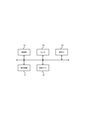
- FIG. 4 is a diagram showing a hardware configuration included in the air conditioner 1 of the present embodiment.
- the air conditioner 1 includes a control unit 101, a sensor 102, and an operation I / F 103 in addition to the indoor heat exchanger 10 and the indoor blower fan 20 described in FIGS. 1 to 3.
- Each piece of hardware is electrically connected by a bus. Since the indoor heat exchanger 10 and the indoor blower fan 20 have already been described, the details will be omitted here.
- the control unit 101 is a device that executes a program that controls the operation of the air conditioner 1 and performs predetermined processing, and can be configured by, for example, a CPU (Central Processing Unit).
- the control unit 101 can control the operation of various hardware.
- the control unit 101 of the present embodiment can control the operation of each hardware in various air-conditioning operation modes such as cooling operation, dehumidifying operation, and heating operation.
- the sensor 102 is a device that measures the temperature, humidity, etc. of the space in which the air conditioner 1 is installed.
- the control unit 101 can obtain a desired indoor environment by performing control based on the measured value of the sensor 102 during the air-conditioned operation.
- the operation I / F 103 is an interface for receiving a signal transmitted from an operation device such as a remote controller used by the user.
- the control unit 101 controls the operation of the air conditioner 1 based on the signals.
- the operation signal include operation or stop of the air conditioning device 1, temperature setting, wind direction setting, timer setting, air conditioning operation mode switching, start of internal cleaning operation, and the like.
- the control unit 101 of the present embodiment can control the operation of each hardware by an operation mode for cleaning the inside of the housing.
- an operation mode for cleaning the inside of the housing there is a mode for cleaning dirt on the drain pan 30 (hereinafter referred to as a cleaning mode).
- the control unit 101 controls to cool the indoor heat exchanger 10 to lower the temperature of the metal member 32, and causes dew, frost, or ice to adhere to the metal member 32.
- the control unit 101 controls to heat the indoor heat exchanger 10 to raise the temperature of the metal member 32.
- control unit 101 may control to drive the indoor blower fan 20.
- the indoor blower fan 20 By driving the indoor blower fan 20 in the cleaning mode, air containing moisture can be taken into the housing, and dew, frost, or ice can be easily attached to the metal member 32. Further, by driving the indoor blower fan 20 while the cleaning mode is being executed, dew condensation on the indoor blower fan 20 can be prevented, and the cleanliness of the indoor blower fan 20 can be maintained.
- control unit 101 of the present embodiment may perform an operation of lowering the temperature of the indoor heat exchanger 10 and causing dew condensation on the surface of the indoor heat exchanger 10 before operating in the cleaning mode.
- the indoor heat exchanger 10 and the metal member 32 can be brought into contact with each other via moisture, and the thermal conductivity between the indoor heat exchanger 10 and the metal member 32 is improved. can. Therefore, in the subsequent cleaning mode, dew, frost, or ice can be easily attached to the metal member 32.
- the control for dew condensation on the indoor heat exchanger 10 may be executed as a dedicated operation mode, or may be performed by air conditioning such as cooling operation.
- control unit 101 of the present embodiment may have an operation mode for raising the temperature of the metal member 32. Since the air conditioner 1 of the present embodiment is in contact with the indoor heat exchanger 10 and the metal member 32, the control unit 101 controls, for example, to raise the temperature of the indoor heat exchanger 10 to a metal. The temperature of the member 32 is raised. By raising the temperature of the metal member 32 in this way, the water remaining in the drain pan 30 can be evaporated, and the cleanliness of the drain pan 30 can be improved.
- the operation mode for raising the temperature of the metal member 32 may be performed after the operation mode for dew condensation on the surface of the indoor heat exchanger 10. As a result, the drain pan 30 can be washed with the condensed water and then the water can be evaporated, and the cleanliness of the drain pan 30 can be further improved.
- Air conditioner 10 ... Indoor heat exchanger, 20 ... Indoor blower fan, 30 ... Drain pan, 31 ... Insulation material, 32 ... Metal member, 40 ... Sheet material, 101 ... Control unit, 102 ... Sensor, 103 ... Operation I / F
Landscapes
- Engineering & Computer Science (AREA)
- Chemical & Material Sciences (AREA)
- Combustion & Propulsion (AREA)
- Mechanical Engineering (AREA)
- General Engineering & Computer Science (AREA)
- Devices For Blowing Cold Air, Devices For Blowing Warm Air, And Means For Preventing Water Condensation In Air Conditioning Units (AREA)
Abstract
【課題】 筐体内部のドレンパンを効率的に清掃する空気調和装置を提供すること。 【解決手段】 空気と熱交換をする室内熱交換器10と、室内熱交換器10の下方に設けられ、室内熱交換器10から生じるドレン水を受けるドレンパン30とを備え、ドレンパン30は、熱交換器10側の面に断熱材31を有し、断熱材31の表面の少なくとも一部に金属部材32が配置されることを特徴とする。
Description
本発明は、筐体の内部を清掃する空気調和装置に関する。
今日では多様な空気調和装置が開発されており、空気調和装置の筐体内部を自動的に清掃して、空気調和運転時における室内空間の快適性を向上する技術が知られている。特に、熱交換器から生じる水を受け、外部に排出するドレンパンには汚れや雑菌などが溜まりやすいことから、定期的な清掃が求められている。
空気調和装置のドレンパンを清掃する技術の一例として、特開2004-205132号公報(特許文献1)が挙げられる。特許文献1にて開示される空気調和装置は、ケーシング内で発生したドレン水を回収するためのドレンパンと、該ドレンパンのドレン水を排出するためのドレンポンプと、該ドレンポンプからドレン水を外部に導くドレン排出管とを備え、ドレンパンの内表面は、銅または銅合金などの銅系材料で形成される一方、ドレンポンプの出口付近に、逆止弁が設けられている。特許文献1によれば、雑菌の繁殖を抑制することができる。
しかしながら特許文献1を始めとする従来技術は、ドレン水によってドレンパンの汚れを洗浄するものであるため、ドレン水が流れない箇所の汚れは洗浄できず、また、冬季などのドレン水が発生しにくい時期には、充分な清掃効果を得ることができない。
そのため、空気調和装置のドレンパンを清掃するさらなる技術が求められていた。
本発明は、上記従来技術における課題に鑑みてなされたものであり、筐体内部のドレンパンを効率的に清掃する空気調和装置を提供することを目的とする。
すなわち、本発明によれば、
空気と熱交換をする熱交換器と、
前記熱交換器の下方に設けられ、前記熱交換器から生じるドレン水を受けるドレンパンと
を備え、
前記ドレンパンは、
前記熱交換器側の面に断熱材を有し、前記断熱材の表面の少なくとも一部に金属部材が配置されることを特徴とする、
空気調和装置が提供される。
空気と熱交換をする熱交換器と、
前記熱交換器の下方に設けられ、前記熱交換器から生じるドレン水を受けるドレンパンと
を備え、
前記ドレンパンは、
前記熱交換器側の面に断熱材を有し、前記断熱材の表面の少なくとも一部に金属部材が配置されることを特徴とする、
空気調和装置が提供される。
本発明によれば、筐体内部のドレンパンを効率的に清掃する空気調和装置が提供できる。
以下、本発明を、実施形態をもって説明するが、本発明は後述する実施形態に限定されるものではない。なお、以下に参照する各図においては、共通する要素について同じ符号を用い、適宜その説明を省略するものとする。
図1は、本実施形態の空気調和装置1の構造を示す断面斜視図である。図1に示すように、本実施形態の空気調和装置1は主として、室内熱交換器10と、室内送風ファン20と、ドレンパン30を備えている。また、図示していないが、本実施形態の空気調和装置1は、圧縮機、膨張弁、室外熱交換器、室外送風ファンを備えている。
室内熱交換器10は、主要部品として伝熱管およびフィンを備え、伝熱管内を流れる冷媒と、フィン間を通過する空気との熱交換を行う。
室内送風ファン20は、回転駆動することによって空気の流れを生じさせる。室内送風ファン20が室内熱交換器10に送風することで、熱交換された空気が室内空間に吐出され、空気調和を行うことができる。
ドレンパン30は、室内熱交換器10から生じる、冷房運転や除湿運転などによって凝縮した水(以下、「ドレン水」として参照する)を回収する。ドレンパン30が回収したドレン水は、空気調和装置1の外部に排出される。また、本実施形態のドレンパン30は、ドレン水を受ける面に断熱材31を備えて構成される。ドレンパン30の材料は特に限定されないが、一例として樹脂製とすることができ、例えば、ポリスチレン(PS)樹脂やABS樹脂などを採用することができる。なお、本実施形態のドレンパン30の本体の厚さは、ドレンパン30の汚れを効率的に清掃する観点から、0.5mm~4mmとすることが好ましい。
ところで、ドレンパン30には汚れや雑菌など(以下、総称して「汚れ」として参照する)が残存しやすいことから、定期的な清掃が求められる。そこで、本実施形態のドレンパン30は、金属部材32(図1において不図示)を備える構成とすることで、室内熱交換器10から生じるドレン水に加え、金属部材32からも水分を生じさせることができる。したがって、水分をドレンパン30の広範に発生させることができることから、効率的にドレンパン30の汚れを除去することができる。
以下では、金属部材32を備える本実施形態の空気調和装置1の詳細について、図2を以て説明する。図2は、本実施形態における空気調和装置1の側面の断面図である。
本実施形態の空気調和装置1は、空気調和運転時に室内送風ファン20(図2において不図示)が所定の方向に回転駆動することで、図2の矢印で示す方向に空気の流れが生じる。以下では、図2に示す空気調和運転時における空気の流れる方向を基準として、該方向の上流側を空気調和装置1の前方とし、下流側を空気調和装置1の後方として説明する。
本実施形態のドレンパン30は、図2に示すように、室内熱交換器10からのドレン水を受ける面に断熱材31が配置される。断熱材31の例として、発泡スチロールが挙げられるが、特に実施形態を限定するものではない。
また、本実施形態のドレンパン30は、断熱材31の表面の少なくとも一部を覆う金属部材32が配置される。断熱材31と金属部材32とは、接着剤によって固定することができる。
本実施形態の金属部材32は、室内熱交換器10に近接して配置され、室内熱交換器10の一部と接触して配置されてもよい。また、図2に示すように、金属部材32と室内熱交換器10との間には、気密性を向上するためのシート材40が挿入されてもよい。このように、金属部材32と室内熱交換器10とが接触していたり、金属部材32と室内熱交換器10との間にシート材40が挿入されていたりすることで、室内熱交換器10の上流側と下流側とを分離することができる。これによって、空気調和運転時において、室内空間から取り込まれる空気(熱交換される前の空気)と、室内空間に吐出される空気(熱交換された空気)とが分離でき、効率的な熱交換を行うことができる。なお、本実施形態のシート材40は、充分な気密性を確保するために、金属部材32よりも厚いことが好ましい。
また、本実施形態の金属部材32は、熱伝導率が高い材料から構成されることが好ましい。金属部材32は、例えば、一般的な機械部品の材料として用いられるステンレスよりも熱伝導率が高い材料であることが好ましく、実施形態を限定するものではないが、銅やアルミニウムとすることができる。なお、本実施形態の金属部材32の厚さは、ドレンパン30の汚れを効率的に清掃する観点から、0.1mm~2mmとすることが好ましい。
このように、室内熱交換器10と熱伝導率が高い金属部材32とが接触した構成とすることで、室内熱交換器10を低温とした場合に、金属部材32を効率的に冷却することができる。そして、金属部材32の温度の低下に伴って、露、霜または氷を金属部材32の表面に付着させることができる。
特に金属部材32は、一方の面が室内熱交換器10によって冷却されながら、他方の面が断熱材31と接触していることから、室内熱交換器10側の表面の広い範囲に露、霜または氷を付着させやすくでき、この露、霜または氷の水分によってドレンパン30の表面の汚れを清掃することができる。特に、金属部材32の表面に露、霜または氷を付着させることで、ドレンパン30の表面の汚れをより効果的に清掃することができる。さらに、金属部材32とドレンパン30の本体との間に、断熱材31が挿入されていることから、ドレンパン30本体の温度低下を抑制し、ドレンパン30外郭への結露を抑制することができる。
なお、ここでいうドレンパン30の表面の汚れとは、断熱材31や金属部材32の表面の汚れも含むものとする。また、ここでいう室内熱交換器10と金属部材32との接触とは、シート材40を介した接触や、室内熱交換器10の表面に結露した水分を介した接触なども含むものとする。
また、室内熱交換器10と金属部材32とが接触していることから、本実施形態の空気調和装置1が乾燥運転などの高温にする運転を行った場合には、金属部材32の温度も上昇させることができる。これによって、ドレンパン30に残留する水分を蒸発させることができ、ドレンパン30の清浄性を向上できる。さらに、金属部材32とドレンパン30の本体との間に、断熱材31が挿入されていることから、ドレンパン30本体の温度上昇を抑制でき、室内空間に吐出される空気が過剰に高温となることを防止できる。
乾燥運転では、例えば、金属部材32の温度を45℃以上かつ59℃以下に所定の時間(例えば、10分間)維持するよう、圧縮機、膨張弁または室内送風ファン20を制御する。特に、室内熱交換器10で発生した結露水が金属部材32に残留している状態で、金属部材32の温度を45℃以上かつ59℃以下とすることが望ましい。結露水が存在しない状態で金属部材32を加熱するよりも、結露水が存在する状態で加熱したほうが、カビや細菌に作用する熱量が多くなるからである。
金属部材32に温度センサに配置してもよいが、必ずしも温度センサを配置せずとも室内熱交換器10の温度から金属部材32の温度を計算するようにしてもよい。金属部材32として厚さが0.1mmの銅を用いる場合、周囲の温度が27℃の条件で室内熱交換器10を60℃に加熱したとき、金属部材32の先端(金属部材32と室内熱交換器10との接触又は近接位置から最も離れた位置)の温度は55℃となる。また、周囲の温度が27℃の条件で室内熱交換器10を-20℃に冷却したとき、金属部材32の先端の温度は-12℃となる。このように室内熱交換器10の温度から金属部材32の温度を計算することができる。
また、金属部材32として厚さが0.1mmのステンレスを用いた場合、周囲の温度が27℃の条件で室内熱交換器10を60℃に加熱したとき、金属部材32の先端の温度は36℃となる。また、周囲の温度が27℃の条件で室内熱交換器10を-20℃に冷却したとき、金属部材32の先端の温度は14℃となる。つまり、金属部材32を加熱又は冷却するためには、ステンレスよりも熱伝導率が高い材料であることが好ましい。
ここまで、本発明の基本的な実施形態について説明した。しかしながら、本発明は、上述した実施形態において種々の変形例を採用し得る。図3は、本実施形態における空気調和装置1の変形例を説明する図であり、図2の一部を拡大したものである。なお、図3は、図面の見やすさの観点から一部の部品を省略し、簡素化して図示している点に留意されたい。
図3(a)は、本実施形態の第1の変形例を示す図である。第1の変形例においては、室内熱交換器10の前方に、図3(a)の破線の領域で示す空間を設ける構成とする。このような空間を設けることで、熱交換される前の空気、すなわち水分量が多い空気を該空間に通過させることができる。そのため、水分量が多い空気を温度が低下した金属部材32に接触させることができ、金属部材32に露、霜または氷を付着しやすくできる。
ここで、室内熱交換器10の前方の空間は、図3(a)に示すような寸法とすることが好ましい。すなわち、室内熱交換器10からドレンパン30本体までの距離(開口部)をAとし、室内熱交換器10から金属部材32表面までの距離をBとした場合に、B>0.2Aとなるように空間を設けることが好ましい。図3(a)に示すB>0.2Aを満たす空間を室内熱交換器10の前方に設けることにより、金属部材32に露、霜または氷を付着しやすくでき、ドレンパン30の汚れを効率的に清掃できる。
また、図3(b)は、本実施形態の第2の変形例を示す図である。第2の変形例においては、図3(b)に示すように、金属部材32を断熱材31の表面の一部に配置する構成としている。ここで、第2の変形例の金属部材32は、金属部材32と室内熱交換器10とが最も近接する箇所(図3(b)の破線で示す箇所)および当該箇所よりも前方に配置される。室内熱交換器10の前方に水分量の多い空気が存在することから、金属部材32を配置する範囲を図3(b)に示すようにすることで、効率的に金属部材32に露、霜または氷を付着させることができる。
ここまで、本実施形態の空気調和装置1の機構的な構成について説明した。次に本実施形態の空気調和装置1のハードウェア構成について説明する。図4は、本実施形態の空気調和装置1に含まれるハードウェア構成を示す図である。図4に示すように空気調和装置1は、図1~3において説明した室内熱交換器10、室内送風ファン20の他、制御部101、センサ102、操作I/F103を含んで構成される。各ハードウェアは、バスによって電気的に接続されている。なお、室内熱交換器10および室内送風ファン20については既に説明したため、ここでは詳細は省略する。
制御部101は、空気調和装置1の運転を制御するプログラムを実行し、所定の処理を行う装置であり、例えば、CPU(Central Processing Unit)などによって構成することができる。制御部101は、各種ハードウェアの動作を制御することができる。本実施形態の制御部101は、冷房運転、除湿運転、暖房運転など、種々の空気調和運転モードで以て各ハードウェアの動作を制御することができる。
センサ102は、空気調和装置1が設置された空間の温度や湿度などを測定する装置である。制御部101は、空気調和運転時においてセンサ102の測定値に基づいて制御を行うことで、所望の室内の環境とすることができる。
操作I/F103は、例えばユーザが使用するリモコンなどの操作装置から送信される信号を受信するためのインターフェースである。操作I/F103が各種操作信号を受信すると、制御部101は、当該信号に基づいて空気調和装置1の動作を制御する。操作信号の例としては、空気調和装置1の運転または停止、温度の設定、風向の設定、タイマーの設定、空気調和運転モードの切り替え、内部清掃運転の開始などが挙げられる。
なお、本実施形態の制御部101は、上述した空気調和運転モード以外にも、筐体内部を清掃する運転モードによって各ハードウェアの動作を制御することができる。筐体内部を清掃する運転モードの一例として、ドレンパン30の汚れを清掃するモード(以下、清掃モードとして参照する)が挙げられる。本実施形態における清掃モードでは、制御部101は、室内熱交換器10を冷却する制御を行うことで金属部材32の温度を低下させ、金属部材32に露、霜または氷を付着させる。または、本実施形態における清掃モードでは、制御部101は、室内熱交換器10を加熱する制御を行うことで金属部材32の温度を上昇させる。
また、清掃モードにおいて制御部101は、室内送風ファン20を駆動させる制御を行うこととしてもよい。清掃モードにおいて室内送風ファン20を駆動することで、水分を含む空気を筐体内部に取り込むことができ、金属部材32に露、霜または氷を付着させやすくできる。また、清掃モードの実行中に室内送風ファン20が駆動することにより、室内送風ファン20の結露を防止することができ、室内送風ファン20の清浄性を維持できる。
また、本実施形態の制御部101は、清掃モードで運転する前に、室内熱交換器10の温度を下げ、室内熱交換器10の表面を結露させる運転を行うこととしてもよい。室内熱交換器10を結露させることで、室内熱交換器10と金属部材32とを水分を介して接触させることができ、室内熱交換器10と金属部材32との間の熱伝導性を向上できる。したがって、その後の清掃モードにおいて、金属部材32に露、霜または氷を付着させやすくできる。なお、室内熱交換器10を結露させる制御は、専用の運転モードとして実行されてもよいし、冷房運転などの空気調和によるものであってもよい。
さらに、本実施形態の制御部101は、金属部材32の温度を上昇させる運転モードを有してもよい。本実施形態の空気調和装置1は室内熱交換器10と金属部材32とが接触していることから、制御部101は、例えば、室内熱交換器10を高温にする制御を行うことで、金属部材32の温度を上昇させる。このようにして金属部材32の温度を上昇させることで、ドレンパン30に残留する水分を蒸発させることができ、ドレンパン30の清浄性を向上できる。なお、金属部材32の温度を上昇させる運転モードは、室内熱交換器10の表面を結露させる運転モードの後に行うこととしてもよい。これによって、結露した水分によってドレンパン30を洗浄したうえで水分を蒸発させることができ、ドレンパン30の清浄性をより向上できる。
以上、説明した本発明の実施形態によれば、筐体内部のドレンパンを効率的に清掃する空気調和装置を提供することができる。
以上、本発明について実施形態をもって説明してきたが、本発明は上述した実施形態に限定されるものではなく、当業者が推考しうる実施態様の範囲内において、本発明の作用・効果を奏する限り、本発明の範囲に含まれるものである。
1…空気調和装置、
10…室内熱交換器、
20…室内送風ファン、
30…ドレンパン、
31…断熱材、
32…金属部材、
40…シート材、
101…制御部、
102…センサ、
103…操作I/F
10…室内熱交換器、
20…室内送風ファン、
30…ドレンパン、
31…断熱材、
32…金属部材、
40…シート材、
101…制御部、
102…センサ、
103…操作I/F
Claims (16)
- 空気と熱交換をする熱交換器と、
前記熱交換器の下方に設けられ、前記熱交換器から生じるドレン水を受けるドレンパンと
を備え、
前記ドレンパンは、
前記熱交換器側の面に断熱材を有し、前記断熱材の表面の少なくとも一部に金属部材が配置されることを特徴とする、
空気調和装置。 - 前記金属部材は、ステンレスよりも熱伝導率が高いことを特徴とする、請求項1に記載の空気調和装置。
- 前記金属部材は、前記熱交換器と前記金属部材とが最も近接する位置および当該位置よりも前方に配置されることを特徴とする、請求項1または2に記載の空気調和装置。
- 前記金属部材は、接着剤によって前記断熱材に固定されることを特徴とする、請求項1~3のいずれか1項に記載の空気調和装置。
- 前記ドレンパンの厚さが0.5mm~4mmであることを特徴とする、請求項1~4のいずれか1項に記載の空気調和装置。
- 前記金属部材の厚さが0.1mm~2mmであることを特徴とする、請求項1~5のいずれか1項に記載の空気調和装置。
- 前記熱交換器から前記ドレンパン本体までの距離に対する、前記熱交換器から前記金属部材表面までの距離の比が、0.2よりも大きいことを特徴とする、請求項1~6のいずれか1項に記載の空気調和装置。
- 前記熱交換器と、前記金属部材とが接触していることを特徴とする、請求項1~7のいずれか1項に記載の空気調和装置。
- 前記熱交換器と、前記金属部材との間にシート材が挿入されることを特徴とする、請求項1~7のいずれか1項に記載の空気調和装置。
- 前記シート材は、前記金属部材の厚みよりも厚いことを特徴とする、請求項9に記載の空気調和装置。
- 前記金属部材の表面に霜または氷を付着させる第1の運転モードを有する、請求項1~10のいずれか1項に記載の空気調和装置。
- 前記第1の運転モードは、前記熱交換器に結露を生じさせる第2の運転モードの後に行われることを特徴とする、請求項11記載の空気調和装置。
- 前記第1の運転モードで動作する際に、送風ファンが駆動することを特徴とする、請求項11または12に記載の空気調和装置。
- 前記金属部材の温度を上昇させる第3の運転モードを有する、請求項1~10のいずれか1項に記載の空気調和装置。
- 前記第3の運転モードは、前記熱交換器に結露を生じさせる第2の運転モードの後に行われる、請求項14に記載の空気調和装置。
- 前記第3の運転モードは、前記金属部材に結露が付着した状態で、前記金属部材の温度を45℃以上かつ59℃以下に所定の時間維持する、請求項14または15に記載の空気調和装置。
Priority Applications (2)
| Application Number | Priority Date | Filing Date | Title |
|---|---|---|---|
| PCT/JP2020/027425 WO2022013956A1 (ja) | 2020-07-15 | 2020-07-15 | 空気調和装置 |
| JP2021512283A JP7229341B2 (ja) | 2020-07-15 | 2020-07-15 | 空気調和装置 |
Applications Claiming Priority (1)
| Application Number | Priority Date | Filing Date | Title |
|---|---|---|---|
| PCT/JP2020/027425 WO2022013956A1 (ja) | 2020-07-15 | 2020-07-15 | 空気調和装置 |
Publications (1)
| Publication Number | Publication Date |
|---|---|
| WO2022013956A1 true WO2022013956A1 (ja) | 2022-01-20 |
Family
ID=79555519
Family Applications (1)
| Application Number | Title | Priority Date | Filing Date |
|---|---|---|---|
| PCT/JP2020/027425 Ceased WO2022013956A1 (ja) | 2020-07-15 | 2020-07-15 | 空気調和装置 |
Country Status (2)
| Country | Link |
|---|---|
| JP (1) | JP7229341B2 (ja) |
| WO (1) | WO2022013956A1 (ja) |
Citations (6)
| Publication number | Priority date | Publication date | Assignee | Title |
|---|---|---|---|---|
| JPH02106630A (ja) * | 1988-10-14 | 1990-04-18 | Matsushita Electric Ind Co Ltd | 空気調和機のドレン水処理装置 |
| JP2000249359A (ja) * | 1999-02-26 | 2000-09-12 | Sanyo Electric Co Ltd | 空気調和機 |
| JP2003343873A (ja) * | 2002-05-28 | 2003-12-03 | Matsushita Electric Ind Co Ltd | 空気調和機 |
| JP2004093007A (ja) * | 2002-08-30 | 2004-03-25 | Toshiba Kyaria Kk | 天井埋込型空気調和装置およびドレンパン |
| JP2015017769A (ja) * | 2013-07-12 | 2015-01-29 | 日立アプライアンス株式会社 | 空気調和機 |
| JP6641066B1 (ja) * | 2019-01-10 | 2020-02-05 | 日立ジョンソンコントロールズ空調株式会社 | 空気調和機 |
Family Cites Families (4)
| Publication number | Priority date | Publication date | Assignee | Title |
|---|---|---|---|---|
| JP2000121095A (ja) | 1998-10-14 | 2000-04-28 | Kubota Kucho Kk | 空気調和機の断熱架台 |
| JP3949005B2 (ja) * | 2001-07-16 | 2007-07-25 | 松下電器産業株式会社 | 空気調和機 |
| JP2015140931A (ja) | 2014-01-27 | 2015-08-03 | 日立アプライアンス株式会社 | 空気調和機の室外機 |
| JP2017133700A (ja) | 2016-01-25 | 2017-08-03 | トーキン工業株式会社 | 空気調和機の除菌装置 |
-
2020
- 2020-07-15 JP JP2021512283A patent/JP7229341B2/ja active Active
- 2020-07-15 WO PCT/JP2020/027425 patent/WO2022013956A1/ja not_active Ceased
Patent Citations (6)
| Publication number | Priority date | Publication date | Assignee | Title |
|---|---|---|---|---|
| JPH02106630A (ja) * | 1988-10-14 | 1990-04-18 | Matsushita Electric Ind Co Ltd | 空気調和機のドレン水処理装置 |
| JP2000249359A (ja) * | 1999-02-26 | 2000-09-12 | Sanyo Electric Co Ltd | 空気調和機 |
| JP2003343873A (ja) * | 2002-05-28 | 2003-12-03 | Matsushita Electric Ind Co Ltd | 空気調和機 |
| JP2004093007A (ja) * | 2002-08-30 | 2004-03-25 | Toshiba Kyaria Kk | 天井埋込型空気調和装置およびドレンパン |
| JP2015017769A (ja) * | 2013-07-12 | 2015-01-29 | 日立アプライアンス株式会社 | 空気調和機 |
| JP6641066B1 (ja) * | 2019-01-10 | 2020-02-05 | 日立ジョンソンコントロールズ空調株式会社 | 空気調和機 |
Also Published As
| Publication number | Publication date |
|---|---|
| JPWO2022013956A1 (ja) | 2022-01-20 |
| JP7229341B2 (ja) | 2023-02-27 |
Similar Documents
| Publication | Publication Date | Title |
|---|---|---|
| CN102197269B (zh) | 空调装置 | |
| JP5076745B2 (ja) | 換気空調装置 | |
| TWI659182B (zh) | air conditioner | |
| CN102519190B (zh) | 一种风冷机组除霜的控制方法和系统 | |
| JP6354004B1 (ja) | 空気調和機 | |
| TW201947127A (zh) | 空調機 | |
| CN102252369B (zh) | 立式空调器及用于在其中去除电加热器上积水的方法 | |
| WO2020070892A1 (ja) | 空気調和機、空気調和機の制御方法およびプログラム | |
| CN111684212B (zh) | 空调机 | |
| TW202104807A (zh) | 空調機 | |
| JP2018200127A (ja) | 空気調和機 | |
| CN111536594A (zh) | 空调器及其新风风道防冻结方法和存储介质 | |
| CN115210509A (zh) | 空调机 | |
| JP2002323250A (ja) | 空気調和機 | |
| CN214249880U (zh) | 一种空调室外机及空调器 | |
| JP7008758B1 (ja) | 空気調和装置 | |
| JP7229341B2 (ja) | 空気調和装置 | |
| JP7545856B2 (ja) | 空気調和機 | |
| TWI709714B (zh) | 空調機 | |
| JP4296876B2 (ja) | 空調装置 | |
| JP7179952B2 (ja) | 空気調和機 | |
| JP5099099B2 (ja) | 空気調和機 | |
| JP4178906B2 (ja) | 空気調和機および空気調和機の制御方法 | |
| CN107327974A (zh) | 空调器室外机 | |
| JP7461409B2 (ja) | 空気調和装置 |
Legal Events
| Date | Code | Title | Description |
|---|---|---|---|
| ENP | Entry into the national phase |
Ref document number: 2021512283 Country of ref document: JP Kind code of ref document: A |
|
| 121 | Ep: the epo has been informed by wipo that ep was designated in this application |
Ref document number: 20945047 Country of ref document: EP Kind code of ref document: A1 |
|
| NENP | Non-entry into the national phase |
Ref country code: DE |
|
| 122 | Ep: pct application non-entry in european phase |
Ref document number: 20945047 Country of ref document: EP Kind code of ref document: A1 |