WO2022013934A1 - 蛍光x線分析装置 - Google Patents
蛍光x線分析装置 Download PDFInfo
- Publication number
- WO2022013934A1 WO2022013934A1 PCT/JP2020/027312 JP2020027312W WO2022013934A1 WO 2022013934 A1 WO2022013934 A1 WO 2022013934A1 JP 2020027312 W JP2020027312 W JP 2020027312W WO 2022013934 A1 WO2022013934 A1 WO 2022013934A1
- Authority
- WO
- WIPO (PCT)
- Prior art keywords
- sample
- fluorescent
- rays
- layer
- derived
- Prior art date
Links
- 238000004876 x-ray fluorescence Methods 0.000 title abstract description 7
- XEEYBQQBJWHFJM-UHFFFAOYSA-N Iron Chemical compound [Fe] XEEYBQQBJWHFJM-UHFFFAOYSA-N 0.000 claims abstract description 100
- 229910052782 aluminium Inorganic materials 0.000 claims abstract description 96
- XAGFODPZIPBFFR-UHFFFAOYSA-N aluminium Chemical compound [Al] XAGFODPZIPBFFR-UHFFFAOYSA-N 0.000 claims abstract description 96
- 229910052742 iron Inorganic materials 0.000 claims abstract description 50
- 230000001678 irradiating effect Effects 0.000 claims abstract description 4
- 239000010410 layer Substances 0.000 claims description 75
- 239000011247 coating layer Substances 0.000 claims description 19
- OKTJSMMVPCPJKN-UHFFFAOYSA-N Carbon Chemical compound [C] OKTJSMMVPCPJKN-UHFFFAOYSA-N 0.000 claims description 7
- 229910052799 carbon Inorganic materials 0.000 claims description 7
- PXHVJJICTQNCMI-UHFFFAOYSA-N Nickel Chemical compound [Ni] PXHVJJICTQNCMI-UHFFFAOYSA-N 0.000 description 44
- 229910052759 nickel Inorganic materials 0.000 description 22
- 238000002441 X-ray diffraction Methods 0.000 description 16
- 238000004458 analytical method Methods 0.000 description 14
- 239000002253 acid Substances 0.000 description 11
- 239000000463 material Substances 0.000 description 11
- 239000002904 solvent Substances 0.000 description 11
- 230000002238 attenuated effect Effects 0.000 description 10
- 229910000831 Steel Inorganic materials 0.000 description 6
- 239000000956 alloy Substances 0.000 description 6
- 229910045601 alloy Inorganic materials 0.000 description 6
- 230000000694 effects Effects 0.000 description 6
- 239000010959 steel Substances 0.000 description 6
- 238000007747 plating Methods 0.000 description 5
- 238000010586 diagram Methods 0.000 description 4
- 238000002834 transmittance Methods 0.000 description 4
- 230000004907 flux Effects 0.000 description 3
- 239000012535 impurity Substances 0.000 description 3
- 239000000203 mixture Substances 0.000 description 3
- 229920003229 poly(methyl methacrylate) Polymers 0.000 description 3
- 239000004926 polymethyl methacrylate Substances 0.000 description 3
- PZNSFCLAULLKQX-UHFFFAOYSA-N Boron nitride Chemical compound N#B PZNSFCLAULLKQX-UHFFFAOYSA-N 0.000 description 2
- VEXZGXHMUGYJMC-UHFFFAOYSA-N Hydrochloric acid Chemical compound Cl VEXZGXHMUGYJMC-UHFFFAOYSA-N 0.000 description 2
- 239000004642 Polyimide Substances 0.000 description 2
- 230000002411 adverse Effects 0.000 description 2
- 238000013016 damping Methods 0.000 description 2
- JEIPFZHSYJVQDO-UHFFFAOYSA-N iron(III) oxide Inorganic materials O=[Fe]O[Fe]=O JEIPFZHSYJVQDO-UHFFFAOYSA-N 0.000 description 2
- 229920001721 polyimide Polymers 0.000 description 2
- 230000003449 preventive effect Effects 0.000 description 2
- 229910002703 Al K Inorganic materials 0.000 description 1
- 229910052582 BN Inorganic materials 0.000 description 1
- 229910018493 Ni—K Inorganic materials 0.000 description 1
- 230000015572 biosynthetic process Effects 0.000 description 1
- 238000005266 casting Methods 0.000 description 1
- 230000007797 corrosion Effects 0.000 description 1
- 238000005260 corrosion Methods 0.000 description 1
- 238000001514 detection method Methods 0.000 description 1
- 239000003814 drug Substances 0.000 description 1
- 229940079593 drug Drugs 0.000 description 1
- 239000007788 liquid Substances 0.000 description 1
- 230000008018 melting Effects 0.000 description 1
- 238000002844 melting Methods 0.000 description 1
- 229910052751 metal Inorganic materials 0.000 description 1
- 239000002184 metal Substances 0.000 description 1
- 238000004452 microanalysis Methods 0.000 description 1
- 238000012986 modification Methods 0.000 description 1
- 230000004048 modification Effects 0.000 description 1
- 238000002161 passivation Methods 0.000 description 1
- 230000002093 peripheral effect Effects 0.000 description 1
- 239000000843 powder Substances 0.000 description 1
- 238000004451 qualitative analysis Methods 0.000 description 1
- 238000004445 quantitative analysis Methods 0.000 description 1
- 239000004065 semiconductor Substances 0.000 description 1
- 239000007787 solid Substances 0.000 description 1
- 239000000126 substance Substances 0.000 description 1
- 238000004454 trace mineral analysis Methods 0.000 description 1
Images


Classifications
-
- G—PHYSICS
- G01—MEASURING; TESTING
- G01N—INVESTIGATING OR ANALYSING MATERIALS BY DETERMINING THEIR CHEMICAL OR PHYSICAL PROPERTIES
- G01N23/00—Investigating or analysing materials by the use of wave or particle radiation, e.g. X-rays or neutrons, not covered by groups G01N3/00 – G01N17/00, G01N21/00 or G01N22/00
- G01N23/22—Investigating or analysing materials by the use of wave or particle radiation, e.g. X-rays or neutrons, not covered by groups G01N3/00 – G01N17/00, G01N21/00 or G01N22/00 by measuring secondary emission from the material
- G01N23/223—Investigating or analysing materials by the use of wave or particle radiation, e.g. X-rays or neutrons, not covered by groups G01N3/00 – G01N17/00, G01N21/00 or G01N22/00 by measuring secondary emission from the material by irradiating the sample with X-rays or gamma-rays and by measuring X-ray fluorescence
-
- G—PHYSICS
- G01—MEASURING; TESTING
- G01N—INVESTIGATING OR ANALYSING MATERIALS BY DETERMINING THEIR CHEMICAL OR PHYSICAL PROPERTIES
- G01N2223/00—Investigating materials by wave or particle radiation
- G01N2223/07—Investigating materials by wave or particle radiation secondary emission
- G01N2223/076—X-ray fluorescence
-
- G—PHYSICS
- G01—MEASURING; TESTING
- G01N—INVESTIGATING OR ANALYSING MATERIALS BY DETERMINING THEIR CHEMICAL OR PHYSICAL PROPERTIES
- G01N2223/00—Investigating materials by wave or particle radiation
- G01N2223/30—Accessories, mechanical or electrical features
Definitions
- the present invention relates to a fluorescent X-ray analyzer.
- the fluorescent X-ray analyzer irradiates a solid sample, a powder sample, or a liquid sample with primary X-rays, and detects fluorescent X-rays excited and emitted by the primary X-rays to detect the elements contained in the sample. It performs qualitative and quantitative analysis.
- fluorescent X-ray analyzers are widely used as useful analyzers, and their analysis targets range from the metal field to the food field.
- FIG. 3 is a schematic diagram showing the configuration of a conventional general fluorescent X-ray analyzer.
- the fluorescent X-ray analyzer 101 includes a sample chamber 20 in which the sample S is arranged, and an apparatus housing 60 in which the X-ray source 10 and the detector 30 are arranged inside.
- the sample chamber 20 has a quadrangular plate-shaped sample base 21 and a quadrangular tubular upper chamber 22 having a quadrangular plate-shaped upper surface.
- a circular opening 21a is formed in the central portion of the sample base 21.
- the upper chamber 22 is rotatably attached to the sample base 21 so that the lower surface of one side wall of the upper chamber 22 and one side of the upper surface side of the sample base 21 are axes.
- the inside of the upper chamber 22 is connected to a vacuum pump (not shown), and is exhausted to a vacuum by the vacuum pump. According to such a sample chamber 20, by opening the upper chamber 22, the sample S can be arranged so that the analysis surface of the sample S closes the opening 21a, and after the sample S is arranged, the upper chamber 22 is opened.
- the inside of the upper chamber 22 can be closed and evacuated to a vacuum.
- the device housing 60 has a square cylinder shape having a quadrangular plate-shaped lower surface, and a peripheral edge portion on the lower surface side of the sample base 21 is attached to the upper surface of the side wall surface of the square cylinder shape.
- the X-ray source 10 and the detector 30 are arranged inside the apparatus housing 60.
- the X-ray source 10 is, for example, a point-focus X-ray tube, which has a housing, and has a target (not shown) as an anode and a filament (not shown) as a cathode inside the housing. Have been placed. As a result, by applying a high voltage to the target and a low voltage to the filament, the thermions radiated from the filament collide with the end face of the target, and the primary X-rays generated at the end face of the target are emitted. It is designed to do.
- the X-ray source 10 is fixedly attached to the lower left of the opening 21a of the sample base 21, and is configured such that the primary X-ray emitted from the X-ray source 10 is incident on the opening 21a at an incident angle ⁇ . ing. Therefore, the analysis surface of the sample S is brought into contact with the sample S so as to close the opening 21a, so that the analysis surface of the sample S is irradiated with the primary X-ray at an incident angle ⁇ .
- the detector 30 has, for example, a housing in which an introduction window is formed, and a detection element (semiconductor element) for detecting fluorescent X-rays is arranged inside the housing.
- the detector 30 is fixedly attached to the lower right of the opening 21a of the sample base 21, and is configured so that fluorescent X-rays generated on the analysis surface of the sample S are incident on the introduction window. Therefore, when the analysis surface of the sample S is irradiated with the primary X-rays, the detector 30 detects the fluorescent X-rays generated on the analysis surface of the sample S.
- the sample S is housed in the sample chamber 20 in order to reduce the risk of the user being exposed to the X-rays that have passed through the sample S.
- the sample base 21 and the upper chamber 22 constituting the sample chamber 20 are formed of a shielding material. That is, the sample chamber 20 is formed of a shielding material. It is shown in Japanese Patent Application Laid-Open No. 2011-022163 (Patent Document 1) that, for example, iron having a thickness of 3.2 mm is used as a shielding material.
- FIG. 4 shows the relationship between the thickness of iron and the X-ray transmittance. With reference to FIG.
- Patent Document 2 Japanese Patent Application Laid-Open No. 2004-197151 (Patent Document 2) is available.
- the fluorescent X-rays of nickel generated by the X-rays transmitted through the sample S hitting the sample base 21 and the upper chamber 22 of the sample chamber 20 are also described as “impure rays derived from nickel”, and the X-rays transmitted through the sample S are the samples.
- the fluorescent X-rays of iron generated by hitting the sample base 21 and the upper chamber 22 of the chamber 20 are also referred to as “impure rays derived from iron”.
- Nickel can be an analysis target in the fluorescent X-ray analyzer 101.
- the sample S is a drug, food, chemical, or the like
- a trace amount of nickel can be analyzed for the purpose of measuring impurities in the sample S.
- the impure wire derived from nickel is considered to be a great obstacle to the trace analysis of nickel in the sample S.
- An object of the present invention is to reduce the influence of nickel-derived impure rays and iron-derived impure rays on fluorescent X-ray analysis in a fluorescent X-ray analyzer including an iron sample chamber, while reducing the influence of an acid solvent on the inner surface of the sample chamber.
- the purpose is to suppress the occurrence of darkening.
- the present invention provides the fluorescent X-ray analyzer shown below.
- a fluorescent X-ray analyzer in which at least a part of the inner surface thereof is covered with a layer made of aluminum derived from molten aluminum. This makes it possible to reduce the influence of nickel-derived impurities and iron-derived impurities on fluorescent X-ray analysis. Further, it is possible to suppress the generation of darkening on the inner surface of the sample chamber due to the acid solvent.
- the influence of the nickel-derived impure wire and the iron-derived impure wire on the fluorescent X-ray analysis is reduced, and the surface of the inside of the sample chamber due to the acid solvent is reduced. The occurrence of darkening can be suppressed.
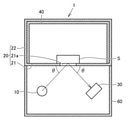
- FIG. 1 is a schematic view showing an example of a fluorescent X-ray analyzer according to the present invention.
- FIG. 2 is a schematic view showing another example of the fluorescent X-ray analyzer according to the present invention.
- FIG. 3 is a schematic view showing an example of a conventional fluorescent X-ray analyzer.
- FIG. 4 is a diagram showing the relationship between the thickness of iron and the X-ray transmittance.
- FIG. 5 is a diagram showing the relationship between the thickness of the layer made of aluminum derived from molten aluminum and the X-ray transmittance.
- FIG. 6 is a diagram showing the relationship between the thickness of the layer made of carbon and the X-ray transmittance.
- FIG. 1 is a schematic view showing an example of a fluorescent X-ray analyzer according to an embodiment of the present invention.
- the same reference numerals are given to the configurations common to the above-mentioned conventional fluorescent X-ray analyzer 101.
- the fluorescent X-ray analyzer 1 includes an X-ray source 10 for irradiating the sample S with X-rays and a detector 30 for detecting the fluorescent X-rays emitted from the sample S by the irradiation of the X-rays. And an iron sample chamber 20 for storing the sample S. At least a part of the inner surface of the sample chamber 20 is covered with a layer 40 made of aluminum derived from molten aluminum. The inner surface of the sample chamber 20 is not nickel-plated.
- the "layer 40 made of aluminum derived from molten aluminum” is also referred to as "molten aluminum layer 40".
- the inner surface of the iron sample chamber 20 is not nickel-plated. Therefore, it is considered that the impure wire derived from nickel is not generated. That is, in the fluorescent X-ray analyzer 1 according to the present invention, the generation of nickel-derived impure rays can be suppressed, and the influence of nickel-derived impure rays on fluorescent X-ray analysis can be reduced.
- the fluorescent X-ray analyzer 1 In the fluorescent X-ray analyzer 1 according to the present invention, at least a part of the inner surface of the iron sample chamber 20 is covered with the molten aluminum layer 40.
- the X-rays generated from the X-ray source 10 pass through the molten aluminum layer 40 and reach the sample base 21 and the upper chamber 22 of the sample chamber 20. As a result, impure wire derived from iron is generated.
- the molten aluminum layer 40 attenuates the impure wire derived from iron.
- the iron-derived impure wire generated from the iron upper chamber 22 is the molten wire coated on the upper chamber 22. It is considered that the material is attenuated when it passes through the aluminum layer 40. That is, in the fluorescent X-ray analyzer 1 according to the present invention, since the generation of iron-derived impure rays is suppressed, the influence of iron-derived impure rays on the fluorescent X-ray analysis can be reduced.
- the molten aluminum layer 40 covers at least a part of the inner surface of the iron sample chamber 20. This makes it possible to reduce the influence of iron-derived impure rays on fluorescent X-ray analysis as described above.
- the molten aluminum layer 40 may cover about 10%, about 20%, about 30%, or about 40% of the inner surface of the iron sample chamber 20. % May be coated, about 50% may be coated, about 60% may be coated, about 70% may be coated, or about 80% may be coated. Alternatively, the entire inner surface of the sample chamber 20 may be covered. In the present specification, "covering substantially the entire inner surface of the sample chamber 20" means that 90% or more of the inner surface of the sample chamber 20 is covered.
- the generated iron-derived impure wire is significantly attenuated by the molten aluminum layer 40, so that the fluorescent X by the iron-derived impure wire
- the effect on line analysis can be significantly reduced.
- the molten aluminum layer 40 is superior in corrosion resistance as compared with nickel plating. Therefore, it is expected that the generation of darkening on the inner surface of the sample chamber 20 due to the acid solvent is suppressed by covering at least a part of the inner surface of the iron sample chamber 20 with the molten aluminum layer 40. When substantially the entire inner surface of the sample chamber 20 is covered with the molten aluminum layer 40, it is expected that the occurrence of darkening of the sample chamber 20 due to the acid solvent is significantly suppressed.
- the fluorescent X-ray analyzer 1 in the fluorescent X-ray analyzer 1 according to the present invention, darkening occurs on the inner surface of the sample chamber 20 due to the acid solvent while the influence of the nickel-derived impure wire and the iron-derived impure wire on the fluorescent X-ray analysis is reduced. Is also suppressed.
- the molten aluminum layer 40 is a layer made of aluminum derived from molten aluminum.
- the molten aluminum layer 40 can be formed, for example, by the steps (1) to (4) shown below. (1) Prepare clean steel as a base material for the iron sample chamber 20. (2) Flux treatment is performed on the clean steel as a pretreatment. (3) Prepare a molten aluminum solution kept above the melting point (about 660 ° C.). (4) Immerse the clean steel that has undergone flux treatment in the molten aluminum solution for several minutes.
- the surface of the steel can be covered with the molten aluminum layer. It is considered that a passivation oxide film is formed on the outermost surface of the molten aluminum layer. It is expected that such an oxide film suppresses the generation of darkening caused by the acid solvent.
- the thickness of the molten aluminum layer 40 is not particularly limited, but the preferable effect of applying the molten aluminum layer 40 instead of nickel plating (that is, the iron sample chamber has a structure in which the inner surface thereof is nickel-plated). It is desirable that the thickness is such that a damping effect (greater than the damping effect of the impure wire derived from iron obtained) can be obtained.
- the thickness of the nickel plating is usually 5 to 15 ⁇ m, and it is considered that the impure wire derived from iron can be attenuated to 30 to 67% depending on the thickness. Therefore, it is desirable that the molten aluminum layer 40 has a thickness capable of attenuating the impure wire derived from iron to less than 30%.
- the impure wire derived from iron that has passed through the molten aluminum layer 40 is about 17.0% as compared with that before passing through the molten aluminum layer 40. It is preferable because it is attenuated to.
- the thickness of the molten aluminum layer 40 is, for example, 100 ⁇ m
- the iron-derived impure wire that has passed through the molten aluminum layer 40 is attenuated to about 8.5% as compared with that before passing through the molten aluminum layer 40, which is more preferable. ..
- the iron-derived impure wire that has passed through the molten aluminum layer 40 is attenuated to about 0.8% as compared with that before passing through the molten aluminum layer 40, which is more preferable. ..
- the thickness of the molten aluminum layer 40 is less than 25 ⁇ m, there may be room for improvement in the attenuation of the impure wire derived from iron. If the thickness of the molten aluminum layer 40 exceeds 1000 ⁇ m, the formation of the molten aluminum layer 40 itself may become difficult.
- the thickness of the molten aluminum layer 40 can be 25 ⁇ m or more and less than 1000 ⁇ m.
- fluorescent X-rays Al—K: 1486eV
- the influence of the fluorescent X-rays of such aluminum on the fluorescent X-ray analysis results is limited. This is because the fluorescent X-rays of aluminum usually have significantly different energies from the elements to be analyzed by the fluorescent X-ray analyzer.
- fluorescent X-rays of aluminum are also referred to as "impure rays derived from aluminum”.
- a coating layer 50 may be further provided on the molten aluminum layer 40.
- the coating layer 50 is a layer that attenuates the impure wire derived from aluminum. It is considered that the aluminum-derived impure wire generated from the molten aluminum layer 40 is attenuated when passing through the coating layer 50 arranged on the molten aluminum layer 40. This is expected to significantly reduce the effect of aluminum-derived impure rays on fluorescent X-ray analysis.
- the material constituting the coating layer 50 attenuates the impure rays derived from aluminum, the material itself does not generate fluorescent X-rays that hinder fluorescent X-ray analysis, and the shape of the molten aluminum layer 40 is, for example, a free curved surface. Even in a complicated case such as, there is no particular limitation as long as it can be arranged on the molten aluminum layer 40.
- the coating layer 50 may be a layer made of carbon, boron nitride (BN), polyimide, polymethylmethacrylate (PMMA), or the like.
- the coating layer 50 is a layer made of carbon. As shown in FIG. 6, when the thickness of the coating layer 50 made of carbon is 50 ⁇ m, the impure wire derived from aluminum that has passed through the coating layer 50 is about 0.04 as compared with that before passing through the coating layer 50. It is attenuated to%. This significantly reduces the effect of aluminum-derived impure rays on X-ray fluorescence analysis. Even when the coating layer 50 is a layer made of BN, polyimide, or PMMA, it is considered that the impure wire derived from aluminum is attenuated to the same extent as the coating layer 50 made of carbon.
- the fluorescent X-ray analyzer has an alloy layer made of a material (for example, iron) constituting the sample chamber and aluminum between the inner surface of the sample chamber and the layer made of aluminum derived from molten aluminum. It is preferable to have.
- the alloy layer preferably has a composition ratio of 5: 1 to 1: 5 between the material constituting the sample chamber and aluminum, and more preferably has a composition ratio of 2: 1 to 1: 2. Most preferably, it has a composition ratio of 1: 1.
- the fluorescent X-ray analyzer has a layer structure having an alloy layer on the inner surface side of the sample chamber as a molten aluminum layer and an aluminum layer on the alloy layer on the inner surface of the sample chamber. It is desirable that the molten aluminum layer has a thickness capable of attenuating the impure wire derived from iron to less than 30%.
- the total thickness of the alloy layer and the aluminum layer may be 25 ⁇ m or more and less than 1000 ⁇ m. can.
- the aluminum layer is preferably 12.5 to 500 ⁇ m, more preferably 25 to 200 ⁇ m, and further preferably 50 to 100 ⁇ m. preferable.
- 1,101 X-ray fluorescence analyzer 10 X-ray source, 20 sample chamber, 21 sample base, 22 upper chamber, 30 detector, 40 molten aluminum layer, 50 coating layer, 60 device housing, 21a opening, S sample.
Abstract
試料にX線を照射するためのX線源と、X線の照射により試料から放出される蛍光X線を検出するための検出器と、試料を収納するための鉄製の試料室とを含み、試料室は、その内部表面の少なくとも一部が溶融アルミニウム由来のアルミニウムからなる層により被覆されている蛍光X線分析装置、および、試料室の内部表面の略全面が溶融アルミニウム由来のアルミニウムからなる層により被覆されている蛍光X線分析装置が提供される。
Description
本発明は、蛍光X線分析装置に関する。
蛍光X線分析装置は、固体試料や粉体試料や液体試料に一次X線を照射し、一次X線により励起されて放出される蛍光X線を検出することによって、その試料に含まれる元素の定性や定量分析を行うものである。現在、蛍光X線分析装置は有用な分析装置として広く用いられており、その分析対象は金属分野から食品分野まで多岐にわたる。
図3は、従来の一般的な蛍光X線分析装置の構成を示す概略図である。蛍光X線分析装置101は、試料Sが内部に配置される試料室20と、X線源10と検出器30とが内部に配置された装置筐体60とを備える。
試料室20は、四角形板状の試料ベース21と、四角形板状の上面を有する四角筒形状の上部チャンバ22とを有する。試料ベース21の中央部には、円形状の開口21aが形成されている。上部チャンバ22の一つの側壁の下面と試料ベース21の上面側の一辺とが軸となるように、上部チャンバ22は試料ベース21に対して回転可能に取り付けられている。そして、上部チャンバ22の内部は、真空ポンプ(図示せず)と接続されており、真空ポンプによって真空に排気されるようになっている。このような試料室20によれば、上部チャンバ22を開くことにより、試料Sの分析面が開口21aを塞ぐように試料Sを配置することができ、試料Sを配置した後、上部チャンバ22を閉めて上部チャンバ22の内部を真空に排気することができる。
装置筐体60は、四角形板状の下面を有する四角筒形状であり、四角筒形状の側壁の上面に試料ベース21の下面側の周縁部が取り付けられている。そして、装置筐体60の内部には、X線源10と検出器30とが配置されている。
X線源10は、たとえば、ポイントフォーカスのX線管球であり、筐体を有し、筐体の内部に陽極であるターゲット(図示せず)と陰極であるフィラメント(図示せず)とが配置されている。これにより、ターゲットに高電圧を印加するとともに、フィラメントに低電圧を印加することで、フィラメントから放射された熱電子をターゲットの端面に衝突させることで、ターゲットの端面で発生した一次X線を出射するようになっている。
X線源10は、試料ベース21の開口21aの左下方に固定して取り付けられており、X線源10から出射される一次X線が開口21a中に入射角θで入射するように構成されている。よって、試料Sの分析面が開口21aを塞ぐように当接されることで、試料Sの分析面が一次X線に入射角θで照射されるようになっている。
検出器30は、たとえば、導入窓が形成された筐体を有し、筐体の内部に蛍光X線を検出する検出素子(半導体素子)が配置されている。そして、検出器30は、試料ベース21の開口21aの右下方に固定して取り付けられており、試料Sの分析面で発生する蛍光X線が導入窓に入射するように構成されている。よって、試料Sの分析面が一次X線に照射されると、検出器30は試料Sの分析面で発生した蛍光X線を検出するようになっている。
X線分析装置101では、試料Sを透過したX線に使用者が被曝する危険を低減すため、試料Sは試料室20内に収納される。試料室20を構成する試料ベース21および上部チャンバ22は、遮蔽材料により形成されている。すなわち、試料室20は遮蔽材料により形成されている。遮蔽材料として、たとえば厚さ3.2mmの鉄が用いられることが、特開2011-022163号公報(特許文献1)に示されている。図4は、鉄の厚さとX線透過率との関係を示している。図4を参照して、遮蔽材料として厚さ15mmの鉄を用いた場合、試料室20を透過する管電圧50kVのX線は10桁減衰されるものとなり、使用者がX線に被曝する危険が大幅に低減される。また、一般的に試料室20の遮蔽材料として鉄を用いる場合、防錆対策としてニッケルメッキが鉄に施される。ニッケルによる鉄の防錆加工に関する特許文献として、たとえば特開2004-197151号公報(特許文献2)がある。
鉄製の試料室20の内部表面にニッケルメッキが施された構造を有する場合、試料Sを透過したX線が試料ベース21や上部チャンバ22に当たった際、ニッケルの蛍光X線(Ni-K:7478eV)を発生させることになる。係るニッケルの蛍光X線は試料Sの分析面で発生する蛍光X線と共に検出器30にて検出され得る。そのため、蛍光X線分析結果に悪影響を及ぼす懸念がある。また、仮に鉄製の試料室20の内部表面にニッケルメッキを施さない場合においても、試料Sを透過したX線が試料室20の試料ベース21や上部チャンバ22に当たった際、鉄の蛍光X線(FE-K:6403eV)を発生させることになる。係る鉄の蛍光X線もまた、試料Sの分析面で発生する蛍光X線と共に検出器30にて検出され得る。そのため、蛍光X線分析結果に悪影響を及ぼす懸念がある。
以下、試料Sを透過したX線が試料室20の試料ベース21や上部チャンバ22に当たり発生するニッケルの蛍光X線は「ニッケル由来の不純線」とも記され、試料Sを透過したX線が試料室20の試料ベース21や上部チャンバ22に当たり発生する鉄の蛍光X線は「鉄由来の不純線」とも記される。
ニッケルは蛍光X線分析装置101における分析対象となり得る。たとえば、試料Sが医薬品、食品、化学薬品等である場合、試料Sの不純物の測定を目的としてニッケルの微量分析が行われ得る。係る場合、ニッケル由来の不純線は試料S中のニッケルの微量分析に対して大きな妨げとなると考えられる。
また、近年蛍光X線分析装置を用いた微量(ppmオーダー)分析のニーズが高まっている。微量分析を行うためには、ppmオーダーの標準試料を準備する必要がある。係る標準試料の調製には塩酸等の酸溶媒が一般的に用いられる。酸溶媒を含む標準試料を蛍光X線分析する際には、酸溶媒が揮発する。揮発した酸溶媒は鉄製の試料室20の内部表面に施されたニッケルメッキを侵食する。その結果、分析の性能自体には影響は与えないものの、試料室20の内部表面に黒ずみが生じ、蛍光X線分析装置の美観が損なわれるという問題もあった。
本発明の目的は、鉄製の試料室を含む蛍光X線分析装置において、ニッケル由来の不純線および鉄由来の不純線による蛍光X線分析に対する影響を低減させつつ、酸溶媒による試料室内部表面における黒ずみの発生を抑制することにある。
本発明は、以下に示す蛍光X線分析装置を提供する。
[1] 試料にX線を照射するためのX線源と、X線の照射により試料から放出される蛍光X線を検出するための検出器と、試料を収納するための鉄製の試料室とを含み、試料室は、その内部表面の少なくとも一部が溶融アルミニウム由来のアルミニウムからなる層により被覆されている、蛍光X線分析装置。これによりニッケル由来の不純線および鉄由来の不純線による蛍光X線分析に対する影響を低減させることができる。さらに酸溶媒による試料室内部表面における黒ずみの発生を抑制することができる。
[1] 試料にX線を照射するためのX線源と、X線の照射により試料から放出される蛍光X線を検出するための検出器と、試料を収納するための鉄製の試料室とを含み、試料室は、その内部表面の少なくとも一部が溶融アルミニウム由来のアルミニウムからなる層により被覆されている、蛍光X線分析装置。これによりニッケル由来の不純線および鉄由来の不純線による蛍光X線分析に対する影響を低減させることができる。さらに酸溶媒による試料室内部表面における黒ずみの発生を抑制することができる。
[2] 試料室は、その内部表面の略全面が溶融アルミニウム由来のアルミニウムからなる層により被覆されている、[1]に記載の蛍光X線分析装置。これによりニッケル由来の不純線および鉄由来の不純線による蛍光X線分析に対する影響を、より十分に低減させることができる。
[3] 溶融アルミニウム由来のアルミニウムからなる層上に更に被覆層を有し、被覆層は、アルミニウムの蛍光X線を減衰させる層である、[1]または[2]に記載の蛍光X線分析装置。これにより、アルミニウム由来の不純線による蛍光X線分析に対する影響も低減させることができる。
[4] 被覆層はカーボンからなる層である、[3]に記載の蛍光X線分析装置。これにより、アルミニウム由来の不純線による蛍光X線分析に対する影響を、より十分に低減させることができる。
本発明によれば、鉄製の試料室を含む蛍光X線分析装置において、ニッケル由来の不純線および鉄由来の不純線による蛍光X線分析に対する影響を低減させつつ、酸溶媒による試料室内部表面における黒ずみの発生を抑制することができる。
以下、本発明の実施形態を説明するが、本発明はこれらに限定されるものではない。ここで本明細書において「A~B」という形式の表記は、範囲の上限下限(すなわちA以上B以下)を意味し、Aにおいて単位の記載がなく、Bにおいてのみ単位が記載されている場合、Aの単位とBの単位とは同じである。
<蛍光X線分析装置>
図1は、本発明の実施形態に係る蛍光X線分析装置の一例を示す概略図である。なお、上述した従来の蛍光X線分析装置101と共通する構成については、同一の参照符号を付している。
図1は、本発明の実施形態に係る蛍光X線分析装置の一例を示す概略図である。なお、上述した従来の蛍光X線分析装置101と共通する構成については、同一の参照符号を付している。
本発明に係る蛍光X線分析装置1は、試料SにX線を照射するためのX線源10と、X線の照射により試料Sから放出される蛍光X線を検出するための検出器30と、試料Sを収納するための鉄製の試料室20とを含む。試料室20は、その内部表面の少なくとも一部が溶融アルミニウム由来のアルミニウムからなる層40により被覆されている。試料室20の内部表面には、ニッケルメッキは施されていない。以下、「溶融アルミニウム由来のアルミニウムからなる層40」は、「溶融アルミニウム層40」とも記される。
本発明に係る蛍光X線分析装置1において、鉄製の試料室20の内部表面にはニッケルメッキが施されていない。そのため、ニッケル由来の不純線が発生することは無いものと考えられる。すなわち、本発明に係る蛍光X線分析装置1においては、ニッケル由来の不純線の発生が抑制され、ニッケル由来の不純線による蛍光X線分析に対する影響を低減させることができる。
本発明に係る蛍光X線分析装置1においては、鉄製の試料室20の内部表面の少なくとも一部が溶融アルミニウム層40により被覆されている。X線源10から発生されるX線は溶融アルミニウム層40を透過し、試料室20の試料ベース21や上部チャンバ22に到達する。結果として、鉄由来の不純線が発生する。
ここで図5に示されるように、溶融アルミニウム層40は鉄由来の不純線を減衰させる。たとえば、図1に示されるように上部チャンバ22の内部表面が溶融アルミニウム層40により被覆されている場合、鉄製の上部チャンバ22から発生した鉄由来の不純線は、上部チャンバ22に被覆された溶融アルミニウム層40を透過する際に減衰されるものと考えられる。すなわち、本発明に係る蛍光X線分析装置1においては、鉄由来の不純線の発生が抑制されるため、鉄由来の不純線による蛍光X線分析に対する影響を低減させることができる。
溶融アルミニウム層40は、鉄製の試料室20の内部表面の少なくとも一部を被覆する。これにより、上述の通り鉄由来の不純線による蛍光X線分析に対する影響を低減させることが可能となる。溶融アルミニウム層40は、鉄製の試料室20の内部表面の約10%を被覆してもよいし、約20%を被覆してもよいし、約30%を被覆してもよいし、約40%を被覆してもよいし、約50%を被覆してもよいし、約60%を被覆してもよいし、約70%を被覆してもよいし、約80%を被覆してもよいし、試料室20の内部表面の略全面を被覆してもよい。本明細書において「試料室20の内部表面の略全面を被覆」とは、試料室20の内部表面の90%以上が被覆されている状態を示す。溶融アルミニウム層40により被覆される試料室20の内部表面の割合を大きくすることにより、発生した鉄由来の不純線が溶融アルミニウム層40により顕著に減衰されるため、鉄由来の不純線による蛍光X線分析に対する影響を顕著に低減させることができる。
溶融アルミニウム層40は、ニッケルメッキと比較して耐蝕性に優れている。そのため、鉄製の試料室20の内部表面の少なくとも一部が溶融アルミニウム層40により被覆されることにより、酸溶媒による試料室20内部表面における黒ずみの発生が抑制されると期待される。試料室20が、その内部表面の略全面が溶融アルミニウム層40により被覆されている場合は、酸溶媒による試料室20の黒ずみの発生が顕著に抑制されると期待される。
すなわち、本発明に係る蛍光X線分析装置1においては、ニッケル由来の不純線および鉄由来の不純線による蛍光X線分析に対する影響が低減されつつ、酸溶媒による試料室20内部表面における黒ずみの発生も抑制されるものである。
《溶融アルミニウム層》
溶融アルミニウム層40は、溶融アルミニウム由来のアルミニウムからなる層である。溶融アルミニウム層40は、たとえば以下に示す(1)~(4)の工程により形成することができる。
(1)鉄製の試料室20の母材となる清浄な鉄鋼を準備すること。
(2)該清浄な鉄鋼に対し、前処理としてフラックス処理を行うこと。
(3)融点(約660℃)以上に保たれた溶融アルミ溶液を準備すること。
(4)フラックス処理を経た該清浄な鉄鋼を、該溶融アルミ溶液中に数分間浸漬すること。
溶融アルミニウム層40は、溶融アルミニウム由来のアルミニウムからなる層である。溶融アルミニウム層40は、たとえば以下に示す(1)~(4)の工程により形成することができる。
(1)鉄製の試料室20の母材となる清浄な鉄鋼を準備すること。
(2)該清浄な鉄鋼に対し、前処理としてフラックス処理を行うこと。
(3)融点(約660℃)以上に保たれた溶融アルミ溶液を準備すること。
(4)フラックス処理を経た該清浄な鉄鋼を、該溶融アルミ溶液中に数分間浸漬すること。
このようして、鉄鋼の表面を溶融アルミニウム層により被覆することが可能となる。溶融アルミニウム層の最表面には、不動態である酸化被膜が形成されていると考えられる。係る酸化被膜により、酸溶媒に起因する黒ずみの発生が抑制されると期待される。
溶融アルミニウム層40の厚みには特に制限は無いが、ニッケルメッキに代えて溶融アルミニウム層40を施したことによる好ましい効果(すなわち鉄製の試料室が、その内部表面にニッケルメッキが施された構造を有する場合において得られる鉄由来の不純線の減衰効果よりも大きな減衰効果)が得られる厚みであることが望ましい。上記ニッケルメッキの厚みは、通常5~15μmであり、当該厚みによって鉄由来の不純線は30~67%に迄、減衰させることができると考えられる。したがって、溶融アルミニウム層40は、鉄由来の不純線を30%未満に迄減衰させることができる厚みを有することが望ましい。
たとえば図5によれば、溶融アルミニウム層40の厚みがたとえば50μmの場合、溶融アルミニウム層40を透過した鉄由来の不純線は、溶融アルミニウム層40を透過する前と比較して約17.0%まで減衰されるので好ましい。溶融アルミニウム層40の厚みがたとえば100μmの場合、溶融アルミニウム層40を透過した鉄由来の不純線は、溶融アルミニウム層40を透過する前と比較して約8.5%まで減衰されるのでより好ましい。溶融アルミニウム層40の厚みがたとえば200μmの場合、溶融アルミニウム層40を透過した鉄由来の不純線は、溶融アルミニウム層40を透過する前と比較して約0.8%まで減衰されるのでさらに好ましい。一方、溶融アルミニウム層40の厚みが25μm未満であると、鉄由来の不純線の減衰に改善の余地が生じる可能性がある。溶融アルミニウム層40の厚みが1000μmを超える場合、溶融アルミニウム層40の形成そのものが困難になる可能性がある。この場合、上記(4)において、フラックス処理を経た清浄な鉄鋼を溶融アルミ溶液中に数分間浸漬することに代えて、上記鉄鋼に対しアルミ鋳造を行う等の他の手段を行うことが合理的となる場合がある。したがって、たとえば溶融アルミニウム層40の厚みは、25μm以上1000μm未満であることができる。
なお、X線源10から発生されるX線が溶融アルミニウム層40に当たることにより、アルミニウムの蛍光X線(Al-K:1486eV)が発生する。しかしながら、係るアルミニウムの蛍光X線が蛍光X線分析結果に与える影響は限定的であると考えられる。通常、アルミニウムの蛍光X線は蛍光X線分析装置にて分析対象となる元素とエネルギーが大きく異なるためである。以下、「アルミニウムの蛍光X線」は、「アルミニウム由来の不純線」とも記される。
《被覆層》
図2を参照して、溶融アルミニウム層40上に更に被覆層50を有してもよい。被覆層50は、アルミニウム由来の不純線を減衰させる層である。溶融アルミニウム層40から発生したアルミニウム由来の不純線は、溶融アルミニウム層40上に配置された被覆層50を透過する際に減衰されるものと考えられる。これにより、アルミニウム由来の不純線による蛍光X線分析に対する影響が顕著に低減されると期待される。
図2を参照して、溶融アルミニウム層40上に更に被覆層50を有してもよい。被覆層50は、アルミニウム由来の不純線を減衰させる層である。溶融アルミニウム層40から発生したアルミニウム由来の不純線は、溶融アルミニウム層40上に配置された被覆層50を透過する際に減衰されるものと考えられる。これにより、アルミニウム由来の不純線による蛍光X線分析に対する影響が顕著に低減されると期待される。
被覆層50を構成する材料は、アルミニウム由来の不純線を減衰させ、その材料自身が蛍光X線分析の障害となる蛍光X線を発生させず、かつ、溶融アルミニウム層40の形状がたとえば自由曲面等の複雑な場合であっても溶融アルミニウム層40上に配置可能であれば、特に制限されない。たとえば被覆層50は、カーボン、窒化ボロン(BN)、ポリイミド、ポリメチルメタクリレート(PMMA)等からなる層であってもよい。
被覆層50は、カーボンからなる層であることが望ましい。図6に示されるように、カーボンからなる被覆層50の厚さが50μmの場合、被覆層50を透過したアルミニウム由来の不純線は、被覆層50を透過する前と比較して約0.04%まで減衰される。これにより、アルミニウム由来の不純線による蛍光X線分析に対する影響が顕著に低減される。なお、被覆層50がBN、ポリイミド、またはPMMAからなる層である場合においても、カーボンからなる被覆層50と同程度にアルミニウム由来の不純線が減衰されるものと考えられる。
ここで本発明に係る蛍光X線分析装置は、上記試料室の内部表面と溶融アルミニウム由来のアルミニウムからなる層との間に、試料室を構成する材料(例えば鉄)とアルミニウムとからなる合金層を有することが好ましい。この合金層は、試料室を構成する材料とアルミニウムとが5:1~1:5となる組成比率を有することが好ましく、2:1~1:2となる組成比率を有することがより好ましく、1:1となる組成比率を有することが最も好ましい。
この場合、蛍光X線分析装置は、上記試料室の内部表面上に、溶融アルミニウム層として試料室の内部表面側の合金層と、上記合金層上のアルミニウム層とを備える層構造を有する。上記溶融アルミニウム層は、鉄由来の不純線を30%未満に迄減衰させることができる厚みを有することが望ましく、たとえば上記合金層とアルミニウム層との合計の厚みを25μm以上1000μm未満とすることができる。さらに溶融アルミニウム層は、上記合金層およびアルミニウム層を備える場合、上記アルミニウム層は、12.5~500μmであることが好ましく、25~200μmであることがより好ましく、50~100μmであることがさらに好ましい。
今回開示された実施の形態及び実施例はすべての点で例示であって、制限的なものではないと考えられるべきである。本発明の範囲は上記した実施の形態及び実施例ではなく請求の範囲によって示され、請求の範囲と均等の意味、及び範囲内でのすべての変更が含まれることが意図される。
1,101 蛍光X線分析装置、10 X線源、20 試料室、21 試料ベース、22 上部チャンバ、30 検出器、40 溶融アルミニウム層、50 被覆層、60 装置筐体、21a 開口、S 試料。
Claims (4)
- 試料にX線を照射するためのX線源と、
前記X線の照射により前記試料から放出される蛍光X線を検出するための検出器と、
前記試料を収納するための鉄製の試料室とを含み、
前記試料室は、その内部表面の少なくとも一部が溶融アルミニウム由来のアルミニウムからなる層により被覆されている、蛍光X線分析装置。 - 前記試料室は、その内部表面の略全面が前記溶融アルミニウム由来のアルミニウムからなる層により被覆されている、請求項1に記載の蛍光X線分析装置。
- 前記溶融アルミニウム由来のアルミニウムからなる層上に更に被覆層を有し、
前記被覆層は、アルミニウムの蛍光X線を減衰させる層である、請求項1または2に記載の蛍光X線分析装置。 - 前記被覆層はカーボンからなる層である、請求項3に記載の蛍光X線分析装置。
Priority Applications (6)
| Application Number | Priority Date | Filing Date | Title |
|---|---|---|---|
| PCT/JP2020/027312 WO2022013934A1 (ja) | 2020-07-14 | 2020-07-14 | 蛍光x線分析装置 |
| EP20945235.8A EP4184153A4 (en) | 2020-07-14 | 2020-07-14 | X-RAY FLUORESCENCE ANALYSER |
| JP2022536010A JP7416254B2 (ja) | 2020-07-14 | 2020-07-14 | 蛍光x線分析装置 |
| US18/015,655 US20230251214A1 (en) | 2020-07-14 | 2020-07-14 | X ray fluorescence analyzer |
| CN202080102888.3A CN115867793A (zh) | 2020-07-14 | 2020-07-14 | 荧光x射线分析装置 |
| TW110117616A TWI821667B (zh) | 2020-07-14 | 2021-05-17 | 螢光x射線分析裝置 |
Applications Claiming Priority (1)
| Application Number | Priority Date | Filing Date | Title |
|---|---|---|---|
| PCT/JP2020/027312 WO2022013934A1 (ja) | 2020-07-14 | 2020-07-14 | 蛍光x線分析装置 |
Publications (1)
| Publication Number | Publication Date |
|---|---|
| WO2022013934A1 true WO2022013934A1 (ja) | 2022-01-20 |
Family
ID=79555359
Family Applications (1)
| Application Number | Title | Priority Date | Filing Date |
|---|---|---|---|
| PCT/JP2020/027312 WO2022013934A1 (ja) | 2020-07-14 | 2020-07-14 | 蛍光x線分析装置 |
Country Status (6)
| Country | Link |
|---|---|
| US (1) | US20230251214A1 (ja) |
| EP (1) | EP4184153A4 (ja) |
| JP (1) | JP7416254B2 (ja) |
| CN (1) | CN115867793A (ja) |
| TW (1) | TWI821667B (ja) |
| WO (1) | WO2022013934A1 (ja) |
Citations (7)
| Publication number | Priority date | Publication date | Assignee | Title |
|---|---|---|---|---|
| US4150179A (en) * | 1977-12-19 | 1979-04-17 | University College Cardiff | Hot dip aluminizing of steel strip |
| JPH06330346A (ja) * | 1993-05-24 | 1994-11-29 | Nippon Steel Corp | アルミメッキ鋼板 |
| JP2004043882A (ja) * | 2002-07-11 | 2004-02-12 | Union Steel Manufacturing Co Ltd | アルミニウム合金メッキ鋼板のメッキ方法 |
| JP2004197151A (ja) | 2002-12-18 | 2004-07-15 | Lucite Japan Kk | 耐食性鉄材の製造方法 |
| JP2011022163A (ja) | 2010-10-29 | 2011-02-03 | Shimadzu Corp | X線分析装置 |
| JP2016109502A (ja) * | 2014-12-04 | 2016-06-20 | 株式会社日立ハイテクサイエンス | 蛍光x線分析装置 |
| JP2016114394A (ja) * | 2014-12-12 | 2016-06-23 | 日鐵住金建材株式会社 | 放射能汚染物質隔離容器 |
Family Cites Families (5)
| Publication number | Priority date | Publication date | Assignee | Title |
|---|---|---|---|---|
| DE2336652A1 (de) * | 1973-07-18 | 1975-01-30 | Siemens Ag | Schichtsystem zur absorption von roentgenstrahlen |
| US6266390B1 (en) * | 1998-09-21 | 2001-07-24 | Spectramet, Llc | High speed materials sorting using x-ray fluorescence |
| US10175184B2 (en) * | 2015-06-22 | 2019-01-08 | Moxtek, Inc. | XRF analyzer for light element detection |
| FR3052259B1 (fr) * | 2016-06-02 | 2023-08-25 | Avenisense | Capteur, procede de calibration d'un capteur et methode automatisee de suivi en ligne de l'evolution d'un corps liquide |
| JP6642372B2 (ja) * | 2016-10-14 | 2020-02-05 | 株式会社島津製作所 | X線分析装置 |
-
2020
- 2020-07-14 US US18/015,655 patent/US20230251214A1/en active Pending
- 2020-07-14 WO PCT/JP2020/027312 patent/WO2022013934A1/ja unknown
- 2020-07-14 EP EP20945235.8A patent/EP4184153A4/en active Pending
- 2020-07-14 CN CN202080102888.3A patent/CN115867793A/zh active Pending
- 2020-07-14 JP JP2022536010A patent/JP7416254B2/ja active Active
-
2021
- 2021-05-17 TW TW110117616A patent/TWI821667B/zh active
Patent Citations (7)
| Publication number | Priority date | Publication date | Assignee | Title |
|---|---|---|---|---|
| US4150179A (en) * | 1977-12-19 | 1979-04-17 | University College Cardiff | Hot dip aluminizing of steel strip |
| JPH06330346A (ja) * | 1993-05-24 | 1994-11-29 | Nippon Steel Corp | アルミメッキ鋼板 |
| JP2004043882A (ja) * | 2002-07-11 | 2004-02-12 | Union Steel Manufacturing Co Ltd | アルミニウム合金メッキ鋼板のメッキ方法 |
| JP2004197151A (ja) | 2002-12-18 | 2004-07-15 | Lucite Japan Kk | 耐食性鉄材の製造方法 |
| JP2011022163A (ja) | 2010-10-29 | 2011-02-03 | Shimadzu Corp | X線分析装置 |
| JP2016109502A (ja) * | 2014-12-04 | 2016-06-20 | 株式会社日立ハイテクサイエンス | 蛍光x線分析装置 |
| JP2016114394A (ja) * | 2014-12-12 | 2016-06-23 | 日鐵住金建材株式会社 | 放射能汚染物質隔離容器 |
Non-Patent Citations (1)
| Title |
|---|
| See also references of EP4184153A4 |
Also Published As
| Publication number | Publication date |
|---|---|
| EP4184153A1 (en) | 2023-05-24 |
| TWI821667B (zh) | 2023-11-11 |
| JP7416254B2 (ja) | 2024-01-17 |
| US20230251214A1 (en) | 2023-08-10 |
| TW202202835A (zh) | 2022-01-16 |
| CN115867793A (zh) | 2023-03-28 |
| JPWO2022013934A1 (ja) | 2022-01-20 |
| EP4184153A4 (en) | 2024-04-17 |
Similar Documents
| Publication | Publication Date | Title |
|---|---|---|
| CN108508052B (zh) | 基于参考元素的x射线荧光薄层质量厚度测量系统及方法 | |
| Hofmann | Practical surface analysis: state of the art and recent developments in AES, XPS, ISS and SIMS | |
| US5226067A (en) | Coating for preventing corrosion to beryllium x-ray windows and method of preparing | |
| TW201209847A (en) | Thick targets for transmission x-ray tubes | |
| Müller et al. | Absolute determination of cross sections for resonant Raman scattering on silicon | |
| Wolstenholme | Auger electron spectroscopy: practical application to materials analysis and characterization of surfaces, interfaces, and thin films | |
| WO2022013934A1 (ja) | 蛍光x線分析装置 | |
| JPH11304733A (ja) | 可搬型蛍光x線分析計 | |
| US8437451B2 (en) | X-ray shutter arrangement | |
| JPH04270953A (ja) | 元素分析方法および元素分析装置ならびに薄膜形成装置 | |
| AU2009263350B2 (en) | Gas charge container, atom probe apparatus, and method for analyzing hydrogen position in material | |
| EP1554566B1 (en) | Method and apparatus for in situ depositing of neutral cs under ultra-high vacuum to analytical ends | |
| JP5783318B1 (ja) | 微量炭素定量分析装置および微量炭素定量分析方法 | |
| Bador et al. | Advances in low-energy electron-induced X-ray spectroscopy (LEEIXS) | |
| Pineda | Thick target particle-induced x-ray emission | |
| Procop | Estimation of absorbing layer thicknesses for an Si (Li) detector | |
| Russ et al. | Routine use of a second‐generation windowless detector for energy‐dispersive ultra‐light element X‐ray analysis | |
| Procop et al. | Improvements of the low‐energy performance of a micro‐focus x‐ray source for XRF analysis with the SEM | |
| Datta et al. | Simultaneous quantification of Zr, Cr and Cu in copper alloy matrix using charged particle activation analysis | |
| Perlea et al. | Reassessment of standardless XRF and PIXE analysis of some dental materials used in endodontics and orthodontics | |
| KR950010390B1 (ko) | 전반사 형광 x선 분석 장치 | |
| Spolnik et al. | Quantitative analysis of metallic ultra‐thin films by grazing‐exit electron probe x‐ray microanalysis | |
| Kumar et al. | Depth profiling of nitrogen using 429 keV and 897 keV resonances in the 15N (p, αγ) 12C reaction | |
| Tsompopoulou et al. | Energy dispersive x-ray fluorescence spectroscopy and applications in material science | |
| Musket | Energy-dispersive X-ray analysis for Carbon on and in Steels |
Legal Events
| Date | Code | Title | Description |
|---|---|---|---|
| 121 | Ep: the epo has been informed by wipo that ep was designated in this application |
Ref document number: 20945235 Country of ref document: EP Kind code of ref document: A1 |
|
| ENP | Entry into the national phase |
Ref document number: 2022536010 Country of ref document: JP Kind code of ref document: A |
|
| NENP | Non-entry into the national phase |
Ref country code: DE |
|
| ENP | Entry into the national phase |
Ref document number: 2020945235 Country of ref document: EP Effective date: 20230214 |