WO2022009774A1 - 回転電機および回転電機の製造方法 - Google Patents
回転電機および回転電機の製造方法 Download PDFInfo
- Publication number
- WO2022009774A1 WO2022009774A1 PCT/JP2021/024954 JP2021024954W WO2022009774A1 WO 2022009774 A1 WO2022009774 A1 WO 2022009774A1 JP 2021024954 W JP2021024954 W JP 2021024954W WO 2022009774 A1 WO2022009774 A1 WO 2022009774A1
- Authority
- WO
- WIPO (PCT)
- Prior art keywords
- fan
- iron core
- shaped portion
- circumferential direction
- electric machine
- Prior art date
- Legal status (The legal status is an assumption and is not a legal conclusion. Google has not performed a legal analysis and makes no representation as to the accuracy of the status listed.)
- Ceased
Links
Images







Classifications
-
- H—ELECTRICITY
- H02—GENERATION; CONVERSION OR DISTRIBUTION OF ELECTRIC POWER
- H02K—DYNAMO-ELECTRIC MACHINES
- H02K1/00—Details of the magnetic circuit
- H02K1/06—Details of the magnetic circuit characterised by the shape, form or construction
- H02K1/22—Rotating parts of the magnetic circuit
-
- H—ELECTRICITY
- H02—GENERATION; CONVERSION OR DISTRIBUTION OF ELECTRIC POWER
- H02K—DYNAMO-ELECTRIC MACHINES
- H02K1/00—Details of the magnetic circuit
- H02K1/06—Details of the magnetic circuit characterised by the shape, form or construction
- H02K1/22—Rotating parts of the magnetic circuit
- H02K1/27—Rotor cores with permanent magnets
-
- H—ELECTRICITY
- H02—GENERATION; CONVERSION OR DISTRIBUTION OF ELECTRIC POWER
- H02K—DYNAMO-ELECTRIC MACHINES
- H02K15/00—Processes or apparatus specially adapted for manufacturing, assembling, maintaining or repairing of dynamo-electric machines
- H02K15/02—Processes or apparatus specially adapted for manufacturing, assembling, maintaining or repairing of dynamo-electric machines of stator or rotor bodies
-
- H—ELECTRICITY
- H02—GENERATION; CONVERSION OR DISTRIBUTION OF ELECTRIC POWER
- H02K—DYNAMO-ELECTRIC MACHINES
- H02K21/00—Synchronous motors having permanent magnets; Synchronous generators having permanent magnets
- H02K21/12—Synchronous motors having permanent magnets; Synchronous generators having permanent magnets with stationary armatures and rotating magnets
- H02K21/14—Synchronous motors having permanent magnets; Synchronous generators having permanent magnets with stationary armatures and rotating magnets with magnets rotating within the armatures
Definitions
- This application relates to a rotary electric machine and a method for manufacturing a rotary electric machine.
- one of the methods to improve the output of the rotary electric machine by increasing the amount of magnets used for each magnetic pole of the rotor is a structure in which magnets are radially embedded in the iron core of the rotor and each magnetic pole is directed in the tangential direction of the rotor.
- the iron core and the magnet are alternately arranged in the circumferential direction of the rotor.
- a concave pole type rotor in which the number of magnets incorporated in the rotor is halved is also used.
- half of the magnets and the iron cores alternately arranged in the circumferential direction of the rotor are reduced.
- magnets arranged in the circumferential direction alternately invert the polarities, but magnets having a polarity in one of them is omitted (see, for example, Patent Document 1).
- iron cores are arranged on both sides in the circumferential direction of the magnet. That is, a hole for arranging the magnet is provided in the iron core, and the magnet is incorporated in the hole to assemble the rotor.
- the inner dimension of the hole In order to incorporate a magnet into the hole of the iron core, the inner dimension of the hole must be larger than the outer dimension of the magnet.
- the present application discloses a technique for solving the above-mentioned problems, and of a rotary electric machine and a rotary electric machine capable of fixing a magnet to an iron core while suppressing damage to the magnet as compared with the case of inserting a magnet between iron cores.
- the purpose is to provide a manufacturing method.
- the rotary electric machine disclosed in the present application is formed by laminating a plurality of thin plates, and is supported by an annular portion attached to a rotary shaft and the annular portion, and is arranged in a circumferential direction at intervals of a first fan shape.
- a first iron core and a second iron core having a portion and a second fan-shaped portion laminated on the first fan-shaped portion and connected by a connection between the plurality of thin plates, respectively, the first iron core.
- the first fan-shaped portion of the iron core and the magnet attached to one side surface of the second fan-shaped portion in the circumferential direction are provided, and the second iron core faces the first iron core and is attached to the rotating shaft.
- the second fan-shaped portion of the first iron core and the first fan-shaped portion of the second iron core are alternately arranged in the circumferential direction, and the magnet is arranged in the same plane. It is supported by the annular portion of the second iron core at every other place by a connecting portion provided on one side surface in the circumferential direction and the side surface in the circumferential direction opposite to the circumferential direction.
- the method for manufacturing a rotary electric machine disclosed in the present application is formed by laminating a plurality of thin plates, and is supported by an annular portion attached to a rotary shaft and the annular portion, and is arranged at intervals in the circumferential direction.
- a first iron core and a second iron core each having a first fan-shaped portion and a second fan-shaped portion laminated on the first fan-shaped portion and connected by a connection between the plurality of thin plates, respectively.
- a step of rotating the second iron core around a shaft to fix the magnet to the first iron core and the second iron core is provided, and the second fan-shaped portion of the first iron core is provided.
- the first fan-shaped portion of the second iron core is provided at every other place in the same plane by a connecting portion provided on one side surface in the circumferential direction and the side surface in the circumferential direction opposite to the one side surface in the circumferential direction in which the magnet is arranged. It is supported by the annular portion of the second iron core.
- a method for manufacturing a rotary electric machine and a rotary electric machine capable of fixing a magnet to the iron core while suppressing damage to the magnet as compared with the case of inserting a magnet between the iron cores is obtained. be able to.
- FIG. It is a perspective view which shows the modification of the rotor by Embodiment 1.
- FIG. It is a perspective view which shows the holding member of the rotor by Embodiment 1.
- FIG. It is a perspective view which shows the state which attached the holding member to the rotor by Embodiment 1.
- FIG. It is a perspective view which shows the assembly process of the rotor by Embodiment 2.
- FIG. It is a perspective view which shows the assembly process of the rotor by Embodiment 2.
- FIG. It is a perspective view which shows the modification of the process of assembling a rotor by Embodiment 2.
- FIG. It is a perspective view which shows the modification of the process of assembling a rotor by Embodiment 2.
- FIG. It is a perspective view which shows the modification of the process of assembling a rotor by Embodiment 2.
- FIG. 1 It is a perspective view which shows the state which disassembled the modification of the rotor by Embodiment 2.
- FIG. It is sectional drawing which shows the laminated body of the rotor by Embodiment 3.
- FIG. It is sectional drawing which shows the laminated body of the rotor by Embodiment 3.
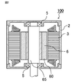
- FIGS. 1 and 2 are cross-sectional views showing a rotary electric machine according to the first embodiment.
- FIG. 1 shows a cross section perpendicular to the axial direction of the rotary electric machine 100
- FIG. 2 shows a cross section parallel to the axial direction of the rotary electric machine 100.
- the rotary electric machine 100 rotates with the motor frame 2, the cylindrical stator 3 fixed in the motor frame 2, and the outer peripheral surface facing the inner peripheral surface of the stator 3. It has a child 6.
- the stator 3 is formed by winding a stator winding 32 around a stator core 31.
- An insulating member for preventing electrical short-circuiting between the stator core 31 and the stator winding 32 is arranged, but it is omitted in FIG. 1.
- the stator winding 32 is composed of a group of three or more polyphase windings, and a predetermined current is sequentially applied to the windings of each phase according to the phase of the rotor 6 by using a control device (not shown). By doing so, the rotor 6 is rotated.
- the rotor 6 is arranged with a constant gap between the rotor 6 and the inner peripheral surface of the stator 3.
- the rotor 6 has a rotor core 60, a permanent magnet 8 and a rotating shaft 65, and the rotating shaft 65 is rotatably supported by a motor frame 2 via a bearing 5 on the axially outer side of the stator 3. ing.
- the rotor core 60 of the rotary electric machine 100 according to the first embodiment is arranged with an annular portion 61 fitted to the rotary shaft 65 on the innermost peripheral side and the outermost peripheral side, and the permanent magnet 8 is placed in the circumferential direction.
- Fan-shaped portion 62 has a fan-shaped portion 62 sandwiched from both side surfaces and a connecting portion 63 connecting the annular portion 61 and the fan-shaped portion 62. Further, the fan-shaped portion 62 constitutes a magnetic pole. Fan-shaped portions 62 are provided at intervals (voids) in the circumferential direction, and permanent magnets 8 are incorporated at every other place of the intervals (voids). Therefore, every other interval (void), which is half of those intervals (voids), serves as a magnet arrangement portion for arranging the permanent magnets 8. Therefore, the number of fan-shaped portions 62 is twice that of the permanent magnet 8.
- the magnetic poles of the permanent magnet 8 are perpendicular to the radial direction of the rotor 6, that is, the magnetic poles are directed in the tangential direction of the rotor 6, and each magnetic pole is magnetized in the same direction in the circumferential direction. Since the rotational torque generated in the rotor 6 is output to the outside via the rotary shaft 65, it is necessary to firmly fix the annular portion 61 and the rotary shaft 65 so as to withstand the rotary torque. As a fixing method, press-fitting, welding, or incorporating a detent key is used.
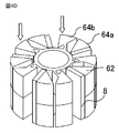
- FIG. 3 is a perspective view showing a laminated body of rotors according to the first embodiment.
- the laminated body 64 is formed by laminating a plurality of thin plates 66. Further, between the thin plates 66 of the laminated body 64, the thin plates 66 laminated in the axial direction are fixed to each other. Adjacent thin plates 66 are generally fixed by caulking, but may be fixed by welding or adhesion.
- the rotor core 60 of the rotary electric machine 100 is made of a thin plate 66 (generally a steel plate) made of a ferromagnetic material. It is formed by combining two laminated bodies 64 in which a large number of laminated bodies 64 are laminated. The two laminated bodies 64 have the same shape, and the rotor core 60 is formed by inverting each other in the axial direction and combining them.
- the laminated body 64 includes an annular portion 61, a fan-shaped portion 62, and a connecting portion 63, similarly to the rotor core 60.
- the rotor core 60 includes the same number of fan-shaped portions 62 as the magnetic poles of the rotor 6, but half of the fan-shaped portions 62 at every other location are one of the two laminated bodies 64. Included in.
- the fan-shaped portion 62 includes a first fan-shaped portion 62a supported by the annular portion 61 via the connecting portion 63, and a second fan-shaped portion 62b not connected to the annular portion 61 via the connecting portion 63. There is.
- the first fan-shaped portion 62a and the second fan-shaped portion 62b are each half the height of the rotor core 60. At this time, the first fan-shaped portion 62a is connected to the annular portion 61 via the connecting portion 63, but the second fan-shaped portion 62b is not directly connected to the connecting portion 63, and the plurality of thin plates 66 are laminated. It is formed by connecting them by connecting them.
- the connecting portion 63 on the inner diameter side is connected to the annular portion 61, and the other end on the outer diameter side is connected to the circumferential side surface of the first fan-shaped portion 62a.
- the first fan-shaped portion 62a has two circumferential side surfaces. Of those peripheral side surfaces, in FIG. 1, the other end of the connecting portion 63 on the outer diameter side is the side surface of the first fan-shaped portion 62a (permanent magnet 8 is arranged) on which the permanent magnet 8 is not arranged. It is connected to a portion (a portion other than the inner peripheral end) of the first fan-shaped portion 62a other than the surface) excluding the inner peripheral end.
- the torque of the rotary electric machine 100 is generated between the magnetic poles of the stator 3 and the rotor 6, and is taken out from the rotary shaft 65 to the outside. Therefore, since torque acts on the fan-shaped portion 62 with respect to the rotating shaft 65, the connecting portion 63 connecting the two must have strength to withstand the torque. Further, centrifugal force is generated in the fan-shaped portion 62 and the permanent magnet 8 during rotation, and it is necessary to support it by the connecting portion 63. In order for the connecting portion 63 to withstand these loads, it is desirable to make the connecting portion 63 short and thick. As described above, there is a trade-off relationship between the magnetically desirable shape and the mechanically desirable shape for the connecting portion 63.
- the assembly is connected to the annular portion 61 via the two connecting portions 63.
- the connecting portion 63 is arranged at the inner peripheral end of the fan-shaped portion 62, the distance between the two connecting portions 63 in the circumferential direction becomes the shortest and is structurally weak against torque. Must widen the circumferential width of the connecting portion 63. In this case, the connecting portion 63 becomes short and thick, which is not desirable in terms of leakage magnetic flux.
- the permanent magnets 8 are arranged between all the fan-shaped portions 62 adjacent in the circumferential direction, the place where the connecting portion 63 is arranged is only the inner peripheral end of the fan-shaped portion 62.
- the permanent magnets 8 are arranged at every other place between the fan-shaped portions 62, the permanent magnets 8 are arranged on the circumferential side surface of the fan-shaped portion 62.
- the connecting portion 63 can be arranged in addition to the inner peripheral end as long as it is in a plane that is not covered.
- the two connecting portions 63 connected to the assembly are compared with the case where the connecting portion 63 is arranged on the inner peripheral end. Since the circumferential distance becomes long, it becomes easy to withstand the torque and the connecting portion 63 can be made thin. Further, the length of the connecting portion 63 is also longer than that when the connecting portion 63 is arranged at the inner peripheral end. Therefore, the magnetic resistance of the connecting portion 63 can be increased as compared with the case where it is arranged at the inner peripheral end, and the leakage magnetic flux is reduced.
- the optimum position of the connecting portion 63 on the side surface of the fan-shaped portion 62 depends on the specifications of the rotary electric machine 100, the shape of the fan-shaped portion 62, and the like. It is possible to improve the characteristics by arranging it at the edge.
- FIGS. 4A to 4E are perspective views showing a process of assembling the rotor according to the first embodiment.
- the laminated structure of the thin plate 66 is omitted in order to avoid complicating the drawings.
- a first laminated body 64a which is a laminated body 64 having an annular portion 61, a fan-shaped portion 62, and a connecting portion 63, is prepared.
- the rotor core 60 is formed by combining the first laminated body 64a and the second laminated body 64b having the same shape as the first laminated body 64a.
- the first laminated body 64a and the second laminated body 64b include a first fan-shaped portion 62a and a second fan-shaped portion 62b, respectively.
- the permanent magnet 8 is attached to the first laminated body 64a.
- the same number of permanent magnets 8 as the fan-shaped portion 62 are arranged on a predetermined direction of the circumferential side surface of the fan-shaped portion 62 of the first laminated body 64a, here, on one side surface in the clockwise direction when viewed from the upper surface.
- an adhesive is applied to the permanent magnet 8 or the fan-shaped portion 62 in advance to bond the two.
- the permanent magnet 8 magnetized in advance may be used to fix both of them by utilizing the magnetic attraction force.
- the magnetic poles are oriented in the circumferential direction and the polarities of all the permanent magnets 8 are the same, as in the polarities of N and S shown in the figure.
- the side in contact with the first laminated body 64a is the N pole, but the polarities may be reversed as long as the directions of all the permanent magnets 8 are aligned.
- the second laminated body 64b After arranging the permanent magnet 8 on the first laminated body 64a, the second laminated body 64b is attached from the axial direction as shown in FIG. 4C. At this time, the position where the second laminated body 64b is rotated in the direction in which the arrangement space of the permanent magnet 8 is widened so that the fan-shaped portion 62 of the second laminated body 64b does not hit the permanent magnet 8 already arranged. Combine from the axial direction with. When the second laminated body 64b is moved in the axial direction, the annular portions 61 of the first laminated body 64a and the second laminated body 64b are in contact with each other in the axial direction, and the state shown in FIG. 4D is obtained.
- the annular portions 61 of the first laminated body 64a and the second laminated body 64b are arranged so as to be overlapped with each other so as to be adjacent to each other in the axial direction.
- the second laminated body 64b is moved in the direction of the arrow with respect to the first laminated body 64a so that the fan-shaped portion 62 of the second laminated body 64b is pressed against the permanent magnet 8. Rotate around the axis. As a result, both sides of the permanent magnet 8 in the circumferential direction are sandwiched between the fan-shaped portion 62 of the first laminated body 64a and the fan-shaped portion 62 of the second laminated body 64b. At this time, the space between the fan-shaped portion 62 of the second laminated body 64b and the permanent magnet 8 is also fixed by adhesion or magnetic attraction as in the case of the first laminated body 64a.
- FIG. 5 is a perspective view showing a modified example of the rotor according to the first embodiment.
- the permanent magnet 8 and the fan-shaped portion 62 are fixed by bonding the two, but as shown in FIG. 5, a magnet holding claw 67 is provided at the outer peripheral end of the fan-shaped portion 62.
- Permanent magnet 8 may be used for radial positioning, or for supporting centrifugal force acting on the permanent magnet 8 during operation of the rotary electric machine 100.
- FIG. 6 is a perspective view showing a rotor holding member according to the first embodiment.
- FIG. 7 is a perspective view showing a state in which the holding member is attached to the rotor according to the first embodiment.
- the rotation direction holding member 68 is provided between the adjacent fan-shaped portions 62, and is attached to the circumferential side surface of the fan-shaped portion 62 opposite to the one side surface in the circumferential direction in which the permanent magnet 8 is arranged. Be done.
- the rotation direction holding member 68 presses the bonding surface when the permanent magnet 8 and the fan-shaped portion 62 are bonded to each other.
- the rotation direction of the laminated bodies 64 which are the laminated bodies 64b, can be fixed.
- the rotation direction holding member 68 is made of a non-magnetic material and contains, for example, a resin or the like.
- the rotation direction holding member 68 may be arranged at intervals between the fan-shaped portions 62, or may be an integral part connected at one end in the axial direction as shown in FIG.
- the conventional structure there is also a problem that it is difficult to sufficiently apply the adhesive to the surface of the magnet and the facing surface of the iron core because the gap between the hole of the iron core and the magnet is small.
- the permanent magnet 8 and the rotor core 60 are bonded, the permanent magnet 8 is not inserted into the magnet arrangement portion, but is pressed in the direction of pressing the bonded surface.
- the permanent magnet 8 can be assembled. Therefore, it is possible to reduce the gap between the magnetic pole surface and the rotor core 60 as much as possible and to secure sufficient adhesive strength at the same time.
- the rotor 6 of the rotary electric machine 100 according to the first embodiment does not need to slide the permanent magnet 8 when the permanent magnet 8 is installed, so that the permanent magnet 8 is easy to install and the permanent magnet 8 is less likely to be damaged.
- the rotary electric machine 100 of the first embodiment is formed by laminating a plurality of thin plates 66, is supported by the annular portion 61 attached to the rotary shaft 65, and is supported by the annular portion 61, and is spaced apart in the circumferential direction.
- a first iron core having a first fan-shaped portion 62a arranged above the ground and a second fan-shaped portion 62b stacked on the first fan-shaped portion 62a and connected by connecting a plurality of thin plates 66, respectively.
- the second fan-shaped portion 62b of the first iron core and the first fan-shaped portion 62a of the second iron core are alternately arranged in the circumferential direction and are in the same plane because they are attached to the rotating shaft 65 so as to face each other.
- the permanent magnet 8 is supported by the annular portion 61 of the second iron core at every other place by the connecting portion 63 provided on the one side surface in the circumferential direction and the side surface in the circumferential direction opposite to the circumferential direction. be.
- a plurality of thin plates 66 are laminated and formed, and the annular portion 61 attached to the rotary shaft 65 and the annular portion 61 are supported and spaced apart from each other in the circumferential direction.
- a first iron core having a first fan-shaped portion 62a arranged above the ground and a second fan-shaped portion 62b stacked on top of the first fan-shaped portion 62a and connected by connecting a plurality of thin plates 66, respectively.
- step of preparing the second iron core the step of attaching the permanent magnet 8 to one side surface in the circumferential direction of the first fan-shaped portion 62a and the second fan-shaped portion 62b of the first iron core, and the step of attaching the second iron core to the second.
- a step of rotating the second iron core around the shaft and fixing the permanent magnet 8 to the first iron core and the second iron core is provided, and the second fan-shaped portion 62b and the second of the first iron core are provided.
- the first fan-shaped portion 62a of the iron core of No. 2 is provided at every other place in the same plane by the connecting portion 63 provided on the side surface in the circumferential direction opposite to the one side surface in the circumferential direction in which the permanent magnet 8 is arranged. It is supported by the annular portion 61 of the second iron core.
- the first iron core which is the first laminated body 64a and the second laminated body 64b are the first laminated body 64a while suppressing the damage of the permanent magnet 8. It is possible to obtain a rotary electric machine 100 and a method for manufacturing the rotary electric machine 100 in which the permanent magnet 8 can be fixed to the iron core of 2.
- Embodiment 2. 8A and 8B are perspective views showing a process of assembling the rotor according to the second embodiment.
- the rotary electric machine 100 according to the second embodiment will be described focusing on a portion different from the first embodiment.
- the first laminated body 64a and the second laminated body 64b each have an annular portion 61, a fan-shaped portion 62, and a connecting portion 63, and the fan-shaped portion 62 included therein has a rotor 6 respectively.
- the fact that the number of poles is half of that of the first embodiment is the same as that of the first embodiment.
- the configuration in which the fan-shaped portions 62 in contact with both sides of the permanent magnet 8 in the circumferential direction are members of different laminated bodies 64 is also the same as that of the first embodiment.
- the rotor core 60 is formed by two laminated bodies 64, but in the second embodiment, the rotor core 60 is formed by three or more laminated bodies 64.
- the laminated body set 69 is formed by assembling the first laminated body 64a, the second laminated body 64b, and the permanent magnet 8 as described in the first embodiment.
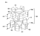
- the height H1 of the fan-shaped portion 62 of the first laminated body 64a and the second laminated body 64b is 1 ⁇ 2 of the height of the rotor core 60.
- FIG. 8B shows the rotor 6 formed by arranging two sets of the laminated body sets 69 formed in FIG. 8A in the axial direction.
- the first laminated body 64a and the second laminated body 64b have a cross section perpendicular to the axis and have a shape symmetrical with respect to a cross section passing through the axial center of the rotor core 60.
- the height of one laminated body is set to half of the rotor core 60, and an example in which two laminated body sets 69 are arranged side by side is shown, but it is also possible to configure three or more sets.
- the permanent magnet 8 is divided into two in the axial direction according to each laminated body set 69, but it is also possible to reduce the number of parts by using one permanent magnet 8 without division. Is.
- a permanent magnet 8 having a length that matches the axial height of the entire rotor core 60 may be incorporated, or the axial length of one permanent magnet 8 may be set to the height of the laminated body set 69.
- permanent magnets 8 for the number of sets of laminated bodies may be arranged in the axial direction.
- 9A and 9B are perspective views showing a modified example of the rotor assembly process according to the second embodiment. In the above case, first, as shown in FIG.
- the first laminated body 64a and the second laminated body 64b are stacked in the axial direction in a state where the space in which the permanent magnet 8 is incorporated is widened.
- a permanent magnet 8 is attached to the side surface of every other fan-shaped portion 62. After that, it is formed by rotating the fan-shaped portion 62 that is not in contact with the permanent magnet 8 and pressing it against the permanent magnet 8.
- FIG. 10 is a perspective view showing a state in which a modified example of the rotor according to the second embodiment is disassembled.
- FIG. 10 describes an example in which the rotor core 60 is composed of three or more laminated bodies including laminated bodies having different shapes.
- the rotor core 60 is formed of a third laminated body 64c, a fourth laminated body 64d, and a fifth laminated body 64e.
- the elements (annular portion 61, fan-shaped portion 62, connecting portion 63) constituting each laminated body are the same as those of the laminated body 64 described in the first embodiment, but their heights are different. ..
- the fourth laminated body 64d the configuration of the fan-shaped portion 62 is different.
- the third laminated body 64c and the fifth laminated body 64e arranged at both ends in the axial direction have a cross section perpendicular to the axis and a symmetrical shape with respect to a cross section passing through the axial center of the rotor core 60.
- the fan-shaped portions 62 (range of H5) connected to the connecting portion 63 are located on both sides in the axial direction.
- H2 the height of the portion connected to the connecting portion 63 of the fan-shaped portion 62 included in the third laminated body 64c is H2 and the height of the portion connected only by laminating the fan-shaped portion 62 is H3, H2 and H4 Are equal, and H3 is half the height of H5.
- the third laminated body 64c and the fifth laminated body 64e are fitted and rotated from both sides in the axial direction to rotate the rotor 6. assemble. With such a configuration, it is possible to reduce the number of laminated bodies 64 while making the height of the portion of the fan-shaped portion 62 connected only by the stacking the same as the configuration described with reference to FIGS. 8 and 9. ..
- each fan-shaped portion 62 is connected to the annular portion 61 via the connecting portion 63, and the other half of the height portion is fan-shaped. It is connected only by laminating the portions 62.
- the height of the portion connected only by laminating the fan-shaped portions 62 also increases. As a result, it is possible that the strength may decrease or the straightness may decrease.
- the rotary electric machine 100 according to the second embodiment since the rotor core 60 is formed by three or more laminated bodies 64, the height of the fan-shaped portion 62 (for example, H1 in FIG.
- the assembly process such as incorporating the permanent magnet 8 or press-fitting into the rotating shaft 65 is a little complicated, but the permanent magnet 8 and the rotation
- the effects of ensuring the adhesive strength with the core 60 and reducing the gap between the permanent magnet 8 and the rotor core 60 can be obtained in the same manner as in the first embodiment.
- Embodiment 3. 11 and 12 are schematic cross-sectional views showing a laminate of rotors according to the third embodiment.
- the laminated body 64 having the annular portion 61, the fan-shaped portion 62, and the connecting portion 63 is the same as that described in the first embodiment.
- what is different from the first embodiment is the axial height of the annular portion 61 and the connecting portion 63.
- the axial height H6 of the annular portion 61 and the connecting portion 63 is the same, and is a value smaller than 1/2 of the height H7 of the fan-shaped portion 62.
- FIG. 12 shows a schematic cross-sectional view of a state in which two of the laminated bodies 64 are combined to form a rotor core 60.
- the height H6 of the annular portion 61 is lower than the height H7 of the fan-shaped portion 62, and the two laminated bodies 64 are assembled as the rotor core 60.
- the annular portion 61 does not come into contact with the axial direction, and the spacer 70 is arranged between them.
- the spacer 70 is a non-magnetic material, for example, a metal such as stainless steel or aluminum, or a resin, and is annular like the annular portion 61. Further, the spacer 70 may not be arranged and a gap corresponding to the thickness thereof may be provided.
- the rotor core 60 is formed of two laminated bodies 64, half of the fan-shaped portions 62 provided in the rotor core 60 are one laminated body 64 and the other half are the other. It is formed by the laminated body 64.
- all of the fan-shaped portions 62 provided have magnetic poles having the same polarity. Therefore, the fan-shaped portions 62 are magnetically connected to each other via the connecting portion 63 and the annular portion 61, but since they have the same poles, no leakage magnetic flux is generated via the above path, that is, the inside of the laminated body 64.
- the annular portion 61 has the same polarity as the fan-shaped portion 62 connected to the annular portion 61.
- the contact portions of the annular portions 61 have different polarities.
- a leakage magnetic flux is generated between the two.
- a non-magnetic spacer 70 or a gap is provided between these annular portions 61 to magnetically block the magnetic flux and reduce the leakage magnetic flux. Therefore, by using the rotor core 60 of the third embodiment, it is possible to improve the output of the rotary electric machine 100 or to reduce the size of the product with the same output.
Landscapes
- Engineering & Computer Science (AREA)
- Power Engineering (AREA)
- Manufacturing & Machinery (AREA)
- Iron Core Of Rotating Electric Machines (AREA)
- Permanent Field Magnets Of Synchronous Machinery (AREA)
- Manufacture Of Motors, Generators (AREA)
- Permanent Magnet Type Synchronous Machine (AREA)
Abstract
回転電機(100)は、複数の薄板(66)を積層して形成され、回転軸(65)に取り付けられた環状部(61)と、環状部(61)に支持され、周方向に間隔を隔てて配置された第1の扇状部(62a)と、第1の扇状部に重ねて積層され、複数の薄板間の連結により繋がれた第2の扇状部(62b)とをそれぞれに有する第1の鉄心(64a)および第2の鉄心(64b)、第1の鉄心の第1の扇状部(62a)および第2の扇状部(62b)の周方向の片側側面に取り付けられた磁石(8)、を備え、第2の鉄心が第1の鉄心に対向して回転軸(65)に取り付けられたことにより、第1の鉄心の第2の扇状部(62b)と第2の鉄心の第1の扇状部(62a)は、周方向に交互に配置され、同一平面内において、磁石(8)が配置された周方向の片側側面と反対側の周方向の側面に設けられた連結部(63)によって、一箇所おきに第2の鉄心の環状部(61)に支持される。
Description
本願は、回転電機および回転電機の製造方法に関するものである。
従来、回転子の各磁極に用いる磁石量を増加させて回転電機の出力を向上させる方法のひとつに、回転子の鉄心内に磁石を放射状に埋め込み、各磁極を回転子の接線方向に向ける構造がある。この場合、回転子の周方向に鉄心と磁石が交互に配置される。
さらに、磁石量を低減して低コスト化するために、回転子に組み込む磁石数を半減させたコンシクエントポール型の回転子も用いられている。これは従来構造であれば回転子の周方向に交互に配置された鉄心と磁石のうち、磁石の半数を削減したものである。従来であれば周方向に並べられた磁石は交互に極性を反転させるが、そのうちの片方の方向の極性の磁石を省略している(例えば、特許文献1参照)。
さらに、磁石量を低減して低コスト化するために、回転子に組み込む磁石数を半減させたコンシクエントポール型の回転子も用いられている。これは従来構造であれば回転子の周方向に交互に配置された鉄心と磁石のうち、磁石の半数を削減したものである。従来であれば周方向に並べられた磁石は交互に極性を反転させるが、そのうちの片方の方向の極性の磁石を省略している(例えば、特許文献1参照)。
磁石の磁極を周方向に向けた縦埋込配置の回転子においては、磁石の周方向両側に鉄心が配置されている。すなわち、鉄心に磁石を配置するための穴部が設けられており、その穴部に磁石を組み込んで回転子を組み立てている。
鉄心の穴部に磁石を組み込むためには、磁石の外寸よりも穴部の内寸の方が大きくなければならない。
鉄心の穴部に磁石を組み込むためには、磁石の外寸よりも穴部の内寸の方が大きくなければならない。
しかしながら、磁石と鉄心との間に大きな空隙があると磁気抵抗が大きくなり回転電機の特性が低下してしまうため、磁石と鉄心との空隙は最小限となっている。このため、磁石を軸方向に挿入する際に、磁石と鉄心との間で磁石が鉄心に接触して磁石に削れまたは割れなどの損傷が発生する問題点があった。
本願は、上記のような課題を解決するための技術を開示するものであり、鉄心間に磁石を挿入するときよりも磁石の損傷を抑制しながら鉄心に磁石を固定できる回転電機および回転電機の製造方法を提供することを目的とする。
本願に開示される回転電機は、複数の薄板を積層して形成され、回転軸に取り付けられた環状部と、前記環状部に支持され、周方向に間隔を隔てて配置された第1の扇状部と、前記第1の扇状部に重ねて積層され、前記複数の薄板間の連結により繋がれた第2の扇状部と、をそれぞれに有する第1の鉄心および第2の鉄心、前記第1の鉄心の前記第1の扇状部および前記第2の扇状部の周方向の片側側面に取り付けられた磁石、を備え、前記第2の鉄心が前記第1の鉄心に対向して前記回転軸に取り付けられたことにより、前記第1の鉄心の前記第2の扇状部と前記第2の鉄心の前記第1の扇状部は、周方向に交互に配置され、同一平面内において、前記磁石が配置された周方向の片側側面と反対側の周方向の側面に設けられた連結部によって、一箇所おきに前記第2の鉄心の前記環状部に支持されているものである。
また、本願に開示される回転電機の製造方法は、複数の薄板を積層して形成され、回転軸に取り付けられる環状部と、前記環状部に支持され、周方向に間隔を隔てて配置された第1の扇状部と、前記第1の扇状部に重ねて積層され、前記複数の薄板間の連結により繋がれた第2の扇状部と、をそれぞれに有する第1の鉄心および第2の鉄心を準備する工程と、前記第1の鉄心の前記第1の扇状部および前記第2の扇状部の周方向の片側側面に磁石を取り付ける工程と、前記第2の鉄心を前記第1の鉄心に対向させて軸方向から挿入し、前記第1の鉄心の前記第2の扇状部と前記第2の鉄心の前記第1の扇状部が、周方向に交互に配置されるように組み合わせる工程と、軸を中心に前記第2の鉄心を回転させて、前記第1の鉄心と前記第2の鉄心に前記磁石を固定する工程と、を備え、前記第1の鉄心の前記第2の扇状部と前記第2の鉄心の前記第1の扇状部は、同一平面内において、前記磁石が配置された周方向の片側側面と反対側の周方向の側面に設けられた連結部によって、一箇所おきに前記第2の鉄心の前記環状部に支持されているものである。
本願に開示される回転電機および回転電機の製造方法によれば、鉄心間に磁石を挿入するときよりも磁石の損傷を抑制しながら鉄心に磁石を固定できる回転電機および回転電機の製造方法を得ることができる。
実施の形態1.
以下、図面に基づいて実施の形態1について説明する。なお、各図面において、同一符号は同一あるいは相当部分を示す。
なお、本願において、特に断りなく「軸方向」、「周方向」、「径方向」、「内周側」、「外周側」、「内周面」、「外周面」、「内径側」、「外径側」と記載された場合は、それぞれ回転子の「軸方向」、「周方向」、「径方向」、「内周側」、「外周側」、「内周面」、「外周面」、「内径側」、「外径側」を示すものとする。
以下、図面に基づいて実施の形態1について説明する。なお、各図面において、同一符号は同一あるいは相当部分を示す。
なお、本願において、特に断りなく「軸方向」、「周方向」、「径方向」、「内周側」、「外周側」、「内周面」、「外周面」、「内径側」、「外径側」と記載された場合は、それぞれ回転子の「軸方向」、「周方向」、「径方向」、「内周側」、「外周側」、「内周面」、「外周面」、「内径側」、「外径側」を示すものとする。
図1および図2は、実施の形態1による回転電機を示す断面図である。図1は回転電機100の軸方向に垂直な断面を示し、図2は回転電機100の軸方向に平行な断面を示す。図1および図2において、回転電機100は、モータフレーム2と、モータフレーム2内に固定された円筒形の固定子3と、固定子3の内周面に外周面を対向させて回転する回転子6とを備えている。固定子3は、固定子鉄心31に固定子巻線32を巻回したものである。固定子鉄心31と固定子巻線32の間には両者が電気的に短絡するのを防止するための絶縁部材が配置されているが、図1では省略している。固定子巻線32は、3以上の多相の巻線群で構成され、制御装置(図示せず)を用いて回転子6の位相に応じて所定の電流を各相の巻線に順次通電することで、回転子6を回転させる。
回転子6は、固定子3の内周面との間に一定の空隙を介して配置されている。回転子6は、回転子鉄心60、永久磁石8および回転軸65を有しており、回転軸65は固定子3の軸方向外側において軸受5を介して回動可能にモータフレーム2に支持されている。
実施の形態1による回転電機100の回転子鉄心60は、最も内周側で回転軸65に嵌合される円環状の環状部61と、最も外周側に配置され、永久磁石8を周方向の両側面から挟みこむ扇状部62と、環状部61と扇状部62とを連結する連結部63とを有している。また、扇状部62は磁極を構成する。周方向に扇状部62が間隔(空隙)を隔てて設けられており、それらの間隔(空隙)の一箇所おきに永久磁石8が組み込まれている。したがって、それらの間隔(空隙)の半数の1か所おきの間隔(空隙)が永久磁石8を配置するための磁石配置部となる。よって扇状部62の数は永久磁石8の2倍となる。
実施の形態1による回転電機100の回転子鉄心60は、最も内周側で回転軸65に嵌合される円環状の環状部61と、最も外周側に配置され、永久磁石8を周方向の両側面から挟みこむ扇状部62と、環状部61と扇状部62とを連結する連結部63とを有している。また、扇状部62は磁極を構成する。周方向に扇状部62が間隔(空隙)を隔てて設けられており、それらの間隔(空隙)の一箇所おきに永久磁石8が組み込まれている。したがって、それらの間隔(空隙)の半数の1か所おきの間隔(空隙)が永久磁石8を配置するための磁石配置部となる。よって扇状部62の数は永久磁石8の2倍となる。
永久磁石8の磁極は回転子6の径方向に垂直、すなわち回転子6の接線方向に磁極が向けられており、各磁極は周方向に同じ向きに着磁されている。
回転子6に発生する回転トルクは回転軸65を介して外部に出力されるため、環状部61と回転軸65とは、回転トルクに耐えるよう強固に固定する必要がある。固定方法として圧入、溶接あるいは、回り止めのキーを組み込むといった手段が取られている。
回転子6に発生する回転トルクは回転軸65を介して外部に出力されるため、環状部61と回転軸65とは、回転トルクに耐えるよう強固に固定する必要がある。固定方法として圧入、溶接あるいは、回り止めのキーを組み込むといった手段が取られている。
図3は、実施の形態1による回転子の積層体を示す斜視図である。図3に示すように、積層体64は複数の薄板66を積層して形成されている。また、積層体64の各々の薄板66間は、軸方向に積層された薄板66同士で固定されている。隣接する薄板66同士は、抜きかしめによって固定する方法が一般的であるが、溶接、あるいは接着といった方法で固定してもよい。
積層体64の組み合わせ方法、永久磁石8の組み込み方法は後述するが、実施の形態1による回転電機100の回転子鉄心60は、強磁性体の素材からなる薄板66(一般的には鋼板)を多数積層した積層体64を2つ組み合わせて形成されている。2つの積層体64は同形状であり、軸方向に互いに反転させて組み合わせることにより回転子鉄心60を形成する。積層体64は、回転子鉄心60と同様に環状部61、扇状部62、連結部63を備えている。回転子鉄心60には回転子6の磁極と同数の扇状部62が含まれているが、そのうちの1か所おきの半数の扇状部62が2つの積層体64のうちの一方の積層体64に含まれている。
扇状部62は、連結部63を介して環状部61に支持されている第1の扇状部62aと、連結部63を介して環状部61とつながっていない第2の扇状部62bとを備えている。第1の扇状部62aおよび第2の扇状部62bは、それぞれ回転子鉄心60の半分の高さである。このとき、第1の扇状部62aは、連結部63を介して環状部61とつながっているが、第2の扇状部62bは連結部63とは直接つながっておらず、複数の薄板66の積層間の連結によって繋がって形成されている。
連結部63の内径側の一端は環状部61に繋がっており、外径側の他端は第1の扇状部62aの周方向側面に連結されている。第1の扇状部62aは、2面の周方向側面を有している。それらの周方向側面のうち、図1では、連結部63の外径側の他端は、永久磁石8が配置されていない方の第1の扇状部62a側面(永久磁石8が配置されている面以外の第1の扇状部62a側面)の内周端を除いた箇所(内周端以外の部分)につながっている。
連結部63の内径側の一端は環状部61に繋がっており、外径側の他端は第1の扇状部62aの周方向側面に連結されている。第1の扇状部62aは、2面の周方向側面を有している。それらの周方向側面のうち、図1では、連結部63の外径側の他端は、永久磁石8が配置されていない方の第1の扇状部62a側面(永久磁石8が配置されている面以外の第1の扇状部62a側面)の内周端を除いた箇所(内周端以外の部分)につながっている。
異なる極性の磁極(扇状部62)同士が、連結部63以外の回転子鉄心60の構成部分を介して繋がっていると、回転子6内部で磁束の漏洩が発生し、漏洩した分は回転電機100の動作に寄与しないため性能が低下する。扇状部62に繋がっているのは連結部63だけであり、連結部63を介した経路の磁気抵抗を増大させると漏洩磁束を減らすことができる。連結部63の磁気抵抗を増大させるには連結部63を長く、細くすることが望ましい。
一方、回転電機100のトルクは、固定子3と回転子6の磁極間で発生し、それを回転軸65から外部に取り出す。したがって、回転軸65に対して扇状部62にトルクが作用するため、両者をつないでいる連結部63にはそのトルクに耐える強度が必要である。また、回転時には扇状部62および永久磁石8に遠心力が生じ、連結部63でそれを支持する必要もある。連結部63がこれらの荷重に耐えるには連結部63を短く、太くすることが望ましい。
以上のように、連結部63に対する磁気的に望ましい形状と、機械的に望ましい形状はトレードオフの関係にある。
一方、回転電機100のトルクは、固定子3と回転子6の磁極間で発生し、それを回転軸65から外部に取り出す。したがって、回転軸65に対して扇状部62にトルクが作用するため、両者をつないでいる連結部63にはそのトルクに耐える強度が必要である。また、回転時には扇状部62および永久磁石8に遠心力が生じ、連結部63でそれを支持する必要もある。連結部63がこれらの荷重に耐えるには連結部63を短く、太くすることが望ましい。
以上のように、連結部63に対する磁気的に望ましい形状と、機械的に望ましい形状はトレードオフの関係にある。
2つの扇状部62とその間に挟まれた永久磁石8を一体の組立体として考えると、組立体は2本の連結部63を介して環状部61とつながっている。扇状部62の内周端に連結部63を配置した場合、2本の連結部63の周方向の距離が最短となりトルクに対して構造的に弱くなるため、組立体に作用するトルクに耐えるには連結部63の周方向の幅を広くしなければならない。この場合、連結部63が短く、かつ太くなり漏洩磁束の面では望ましくない。
周方向に隣接する全ての扇状部62間に永久磁石8が配置されている場合には、連結部63を配置する場所は扇状部62の内周端しかない。しかし、実施の形態1による回転電機100の回転子6では、扇状部62間の1箇所おきに永久磁石8が配置されているので、扇状部62の周方向側面のうち永久磁石8の配置されていない面内であれば内周端以外にも連結部63を配置することができる。
周方向に隣接する全ての扇状部62間に永久磁石8が配置されている場合には、連結部63を配置する場所は扇状部62の内周端しかない。しかし、実施の形態1による回転電機100の回転子6では、扇状部62間の1箇所おきに永久磁石8が配置されているので、扇状部62の周方向側面のうち永久磁石8の配置されていない面内であれば内周端以外にも連結部63を配置することができる。
扇状部62の側面の内周端ではない部分(内周端以外の部分)に連結部63を配置すると、内周端に配置した場合と比較して組立体につながる2本の連結部63の周方向距離が長くなるので、トルクに対して耐え易くなり連結部63を細くできる。また、連結部63の長さも内周端に配置した場合より長くなる。したがって、内周端に配置した場合より連結部63の磁気抵抗を大きくすることができ、漏洩磁束が低減する。扇状部62側面のどの位置に連結部63を配置するのが最適であるかは、回転電機100の仕様または扇状部62の形状等によって異なるが、扇状部62の側面に配置することにより内周端に配置するより特性の向上を図ることができる。
図4Aから図4Eは、実施の形態1による回転子の組み立て工程を示す斜視図である。図4Aから図4Eにおいては、図が煩雑になるのを避けるため、薄板66による積層構造を省略する。
まず、図4Aに示すように、環状部61、扇状部62、連結部63を備えた積層体64である第1の積層体64aを準備する。実施の形態1では、第1の積層体64aとこの第1の積層体64aと同一形状を有する第2の積層体64bを組み合わせて回転子鉄心60を形成する。第1の積層体64aと第2の積層体64bは、図3で説明したように、それぞれ第1の扇状部62aと第2の扇状部62bとを備えている。
次に、図4Bに示すように、第1の積層体64aに永久磁石8を取り付ける。具体的には、第1の積層体64aの扇状部62の周方向側面の所定の方向、ここでは上面からみて時計回りの方向の片側側面に扇状部62と同数の永久磁石8を配置する。
まず、図4Aに示すように、環状部61、扇状部62、連結部63を備えた積層体64である第1の積層体64aを準備する。実施の形態1では、第1の積層体64aとこの第1の積層体64aと同一形状を有する第2の積層体64bを組み合わせて回転子鉄心60を形成する。第1の積層体64aと第2の積層体64bは、図3で説明したように、それぞれ第1の扇状部62aと第2の扇状部62bとを備えている。
次に、図4Bに示すように、第1の積層体64aに永久磁石8を取り付ける。具体的には、第1の積層体64aの扇状部62の周方向側面の所定の方向、ここでは上面からみて時計回りの方向の片側側面に扇状部62と同数の永久磁石8を配置する。
このとき、永久磁石8と扇状部62が接する面において、あらかじめ永久磁石8あるいは扇状部62に接着剤を塗布して両者を接着する。また、事前に着磁された永久磁石8を用いて、磁気吸引力を利用して両者を固定してもよい。なお、着磁済みの永久磁石8を組み付ける際には図中に示すN、Sの極性のように、磁極が周方向を向き、かつすべての永久磁石8の極性が同じ方向とする。ここでは、第1の積層体64aに接する方をN極としているが、すべての永久磁石8の向きがそろっていれば極性は逆でもよい。
第1の積層体64aに永久磁石8を配置した後に、図4Cに示すように、第2の積層体64bを軸方向から取り付ける。このとき、すでに配置してある永久磁石8に第2の積層体64bの扇状部62が当たらないように、永久磁石8の配置スペースが広くなる方向に第2の積層体64bを回転させた位置で軸方向から組み合わせる。第2の積層体64bを軸方向に移動させていくと、第1の積層体64aと第2の積層体64bのそれぞれの環状部61同士が軸方向に接して図4Dの状態となる。このとき、すべての扇状部62の上面、下面がそれぞれそろった状態となる。第1の積層体64aと第2の積層体64bの環状部61は、軸方向に隣接するように互いに重ねて配置されている。
次に、図4Eに示すように、第2の積層体64bの扇状部62が永久磁石8に押し当てられるように、第1の積層体64aに対して第2の積層体64bを矢印の方向に軸を中心に回転させる。
これにより、第1の積層体64aの扇状部62と第2の積層体64bの扇状部62によって、永久磁石8の周方向両側が挟まれる状態となる。このとき、第2の積層体64bの扇状部62と永久磁石8との間も、第1の積層体64aの場合と同様に接着または磁気吸引力により固定する。
これにより、第1の積層体64aの扇状部62と第2の積層体64bの扇状部62によって、永久磁石8の周方向両側が挟まれる状態となる。このとき、第2の積層体64bの扇状部62と永久磁石8との間も、第1の積層体64aの場合と同様に接着または磁気吸引力により固定する。
2つの積層体64である第1の積層体64aおよび第2の積層体64bを相対的に回転させて扇状部62間に永久磁石8を挟んだ後に、両者を回転軸65に固定する。環状部61を回転軸65に軸方向から挿入し、圧入、溶接、接着等の手段、あるいは回り止めのキーを組み込んで固定する。以上の工程により、実施の形態1の回転子6は形成される。
図5は、実施の形態1による回転子の変形例を示す斜視図である。図4Aから図4Eにおいては、永久磁石8と扇状部62との固定を両者の接着等によるものを示したが、図5に示すように、扇状部62の外周端に磁石保持爪67を設け、永久磁石8の径方向の位置決め、または回転電機100の動作時に永久磁石8に作用する遠心力の支持に用いてもよい。
図5は、実施の形態1による回転子の変形例を示す斜視図である。図4Aから図4Eにおいては、永久磁石8と扇状部62との固定を両者の接着等によるものを示したが、図5に示すように、扇状部62の外周端に磁石保持爪67を設け、永久磁石8の径方向の位置決め、または回転電機100の動作時に永久磁石8に作用する遠心力の支持に用いてもよい。
図6は、実施の形態1による回転子の保持部材を示す斜視図である。また図7は、実施の形態1による回転子に保持部材を取り付けた状態を示す斜視図である。
第1の積層体64aおよび第2の積層体64bを組み合わせた後、周方向に並んだ扇状部62間の永久磁石8が配置されていない空隙(扇状部62における永久磁石8が配置された側面とは反対側の周方向側面)に回転方向保持部材68を配置する。図7に示すように、回転方向保持部材68は、隣接する扇状部62間に設けられ、扇状部62における永久磁石8が配置された周方向の片側側面とは反対側の周方向側面に取り付けられる。実施の形態1の回転電機100の回転子6では、回転方向保持部材68により、永久磁石8と扇状部62とを接着する際に接着面を押さえること、第1の積層体64aおよび第2の積層体64bである積層体64同士の回転方向を固定することができる。回転方向保持部材68は、非磁性体の素材により形成されており、例えば樹脂等を含んでいる。
第1の積層体64aおよび第2の積層体64bを組み合わせた後、周方向に並んだ扇状部62間の永久磁石8が配置されていない空隙(扇状部62における永久磁石8が配置された側面とは反対側の周方向側面)に回転方向保持部材68を配置する。図7に示すように、回転方向保持部材68は、隣接する扇状部62間に設けられ、扇状部62における永久磁石8が配置された周方向の片側側面とは反対側の周方向側面に取り付けられる。実施の形態1の回転電機100の回転子6では、回転方向保持部材68により、永久磁石8と扇状部62とを接着する際に接着面を押さえること、第1の積層体64aおよび第2の積層体64bである積層体64同士の回転方向を固定することができる。回転方向保持部材68は、非磁性体の素材により形成されており、例えば樹脂等を含んでいる。
また、回転方向保持部材68は、扇状部62間ごとに部材を配置してもよいし、図6に示すように、軸方向の一端で連結された一体の部品としてもよい。従来の構造では、鉄心の穴部と磁石との空隙が少ないため磁石の表面と鉄心との対向面に十分に接着剤を塗布することが難しいという課題もあった。
実施の形態1の回転電機100の回転子6においては、永久磁石8と回転子鉄心60とを接着する場合に、磁石配置部に永久磁石8を挿入するのではなく、接着面を押し付ける方向に永久磁石8を組み付けることができる。そのため、磁極面と回転子鉄心60との隙間を可能な限り少なくすることと、十分な接着強度の確保との両立が可能である。
実施の形態1の回転電機100の回転子6においては、永久磁石8と回転子鉄心60とを接着する場合に、磁石配置部に永久磁石8を挿入するのではなく、接着面を押し付ける方向に永久磁石8を組み付けることができる。そのため、磁極面と回転子鉄心60との隙間を可能な限り少なくすることと、十分な接着強度の確保との両立が可能である。
また、従来の構造では、あらかじめ着磁しておいた磁石を組み付ける場合も、磁石と鉄心が磁気で吸着された状態で磁石を押し込む必要があり、磁石の挿入に大きな荷重が必要なため磁石の損傷の懸念があった。
これに対し、実施の形態1による回転電機100の回転子6は、永久磁石8を組み込み時に永久磁石8を滑らせる必要がないため、組み込み易くかつ永久磁石8が損傷する恐れも少ない。
これに対し、実施の形態1による回転電機100の回転子6は、永久磁石8を組み込み時に永久磁石8を滑らせる必要がないため、組み込み易くかつ永久磁石8が損傷する恐れも少ない。
以上のとおり、実施の形態1の回転電機100は、複数の薄板66を積層して形成され、回転軸65に取り付けられた環状部61と、環状部61に支持され、周方向に間隔を隔てて配置された第1の扇状部62aと、第1の扇状部62aに重ねて積層され、複数の薄板66の連結により繋がれた第2の扇状部62bと、をそれぞれに有する第1の鉄心および第2の鉄心、第1の鉄心の第1の扇状部62aおよび第2の扇状部62bの周方向の片側側面に取り付けられた永久磁石8、を備え、第2の鉄心が第1の鉄心に対向して回転軸65に取り付けられたことにより、第1の鉄心の第2の扇状部62bと第2の鉄心の第1の扇状部62aは、周方向に交互に配置され、同一平面内において、永久磁石8が配置された周方向の片側側面と反対側の周方向の側面に設けられた連結部63によって、一箇所おきに第2の鉄心の環状部61に支持されているものである。
また、実施の形態1の回転電機100の製造方法は、複数の薄板66を積層して形成され、回転軸65に取り付けられる環状部61と、環状部61に支持され、周方向に間隔を隔てて配置された第1の扇状部62aと、第1の扇状部62aに重ねて積層され、複数の薄板66の連結により繋がれた第2の扇状部62bと、をそれぞれに有する第1の鉄心および第2の鉄心を準備する工程と、第1の鉄心の第1の扇状部62aおよび第2の扇状部62bの周方向の片側側面に永久磁石8を取り付ける工程と、第2の鉄心を第1の鉄心に対向させて軸方向から挿入し、第1の鉄心の第2の扇状部62bと第2の鉄心の第1の扇状部62aが、周方向に交互に配置されるように組み合わせる工程と、軸を中心に第2の鉄心を回転させて、第1の鉄心と第2の鉄心に永久磁石8を固定する工程と、を備え、第1の鉄心の第2の扇状部62bと第2の鉄心の第1の扇状部62aは、同一平面内において、永久磁石8が配置された周方向の片側側面と反対側の周方向の側面に設けられた連結部63によって、一箇所おきに第2の鉄心の環状部61に支持されているものである。
実施の形態1の回転電機100および回転電機100の製造方法によれば、永久磁石8の損傷を抑制しながら第1の積層体64aである第1の鉄心と第2の積層体64bである第2の鉄心に永久磁石8を固定できる回転電機100および回転電機100の製造方法を得ることができる。
実施の形態2.
図8Aおよび図8Bは、実施の形態2による回転子の組み立て工程を示す斜視図である。
以下、実施の形態2による回転電機100について、実施の形態1と異なる部分を中心に説明する。
実施の形態2において、第1の積層体64aおよび第2の積層体64bに関しては、環状部61、扇状部62、連結部63をそれぞれ有すること、およびそれに含まれる扇状部62がそれぞれ回転子6の極数の半数であることは、実施の形態1と同じである。また、永久磁石8の周方向の両面に接する扇状部62が、それぞれ異なる積層体64の部材である構成も実施の形態1と同じである。
図8Aおよび図8Bは、実施の形態2による回転子の組み立て工程を示す斜視図である。
以下、実施の形態2による回転電機100について、実施の形態1と異なる部分を中心に説明する。
実施の形態2において、第1の積層体64aおよび第2の積層体64bに関しては、環状部61、扇状部62、連結部63をそれぞれ有すること、およびそれに含まれる扇状部62がそれぞれ回転子6の極数の半数であることは、実施の形態1と同じである。また、永久磁石8の周方向の両面に接する扇状部62が、それぞれ異なる積層体64の部材である構成も実施の形態1と同じである。
実施の形態1では2つの積層体64により回転子鉄心60を構成する形態を示したが、実施の形態2では3以上の積層体64により回転子鉄心60が形成される。
まず図8Aに示すように、第1の積層体64a、第2の積層体64bおよび永久磁石8を実施の形態1で説明したように組み立てることによって積層体セット69を形成する。このとき、第1の積層体64a、第2の積層体64bの扇状部62の高さH1は、回転子鉄心60の高さの1/2である。
まず図8Aに示すように、第1の積層体64a、第2の積層体64bおよび永久磁石8を実施の形態1で説明したように組み立てることによって積層体セット69を形成する。このとき、第1の積層体64a、第2の積層体64bの扇状部62の高さH1は、回転子鉄心60の高さの1/2である。
図8Bは、図8Aで形成した積層体セット69を軸方向に2セット並べて回転子6を形成したものである。第1の積層体64a、第2の積層体64bは軸に垂直な断面であって、回転子鉄心60の軸方向中央を通る断面に関して互いに対称の形状である。ここでは1個の積層体の高さを回転子鉄心60の半分とし、積層体セット69を2個並べた例を示しているが、3セット以上で構成することも可能である。
また、図8Aおよび図8Bの説明では永久磁石8は各積層体セット69に合わせて軸方向に2分割されているが、分割なしの1つの永久磁石8を用いて部品数を減らすことも可能である。
また、図8Aおよび図8Bの説明では永久磁石8は各積層体セット69に合わせて軸方向に2分割されているが、分割なしの1つの永久磁石8を用いて部品数を減らすことも可能である。
つまり、永久磁石8については、回転子鉄心60全体の軸方向高さに合わせた長さの永久磁石8を組み込んでもよいし、1つの永久磁石8の軸方向長さを積層体セット69の高さに合わせて、軸方向に積層体のセット数分の永久磁石8を配置してもよい。ただし、その場合は、図8A、図8Bで示したような積層体セット69を組み立てて、それを複数個並べて回転軸に固定する方法は難しい。
図9Aおよび図9Bは、実施の形態2による回転子の組み立て工程の変形例を示す斜視図である。上記の場合はまず、図9Aに示すように、永久磁石8が組み込まれるスペースを広げた状態で第1の積層体64a、第2の積層体64bを軸方向に積み重ねる。次に、図9Bに示すように、1箇所おきの扇状部62の側面に永久磁石8を取り付ける。この後、永久磁石8が接していない方の扇状部62を回転させて永久磁石8に押し付けることで形成される。
図9Aおよび図9Bは、実施の形態2による回転子の組み立て工程の変形例を示す斜視図である。上記の場合はまず、図9Aに示すように、永久磁石8が組み込まれるスペースを広げた状態で第1の積層体64a、第2の積層体64bを軸方向に積み重ねる。次に、図9Bに示すように、1箇所おきの扇状部62の側面に永久磁石8を取り付ける。この後、永久磁石8が接していない方の扇状部62を回転させて永久磁石8に押し付けることで形成される。
図10は、実施の形態2による回転子の変形例を分解した状態を示す斜視図である。図10では、異なる形状の積層体も含めて3以上の積層体で回転子鉄心60を構成する事例を説明する。ここでは、回転子鉄心60が第3の積層体64c、第4の積層体64d、第5の積層体64eで形成された事例を示している。図10に示すように、各積層体を構成する要素(環状部61、扇状部62、連結部63)は実施の形態1で説明した積層体64と同じであるが、それぞれの高さが異なる。また、第4の積層体64dにおいては扇状部62の構成が異なる。
軸方向の両端部に配置されている第3の積層体64c、第5の積層体64eは軸に垂直な断面であって回転子鉄心60の軸方向中央を通る断面に関して対称の形状である。一方、第3の積層体64cと第5の積層体64eに軸方向両側から挟まれる第4の積層体64dにおいては、連結部63とつながった扇状部62(H5の範囲)の軸方向両側に積層のみでつながった扇状部62(H4の範囲)がある。第3の積層体64cに含まれる扇状部62は連結部63につながっている部分の高さをH2、扇状部62の積層のみで連結されている部分の高さをH3とすると、H2とH4は等しく、H3はH5の1/2の高さとなっている。
第4の積層体64dの扇状部62の側面に永久磁石8を配置した後、軸方向の両側から第3の積層体64c、第5の積層体64eを嵌め込み、回転させることで回転子6を組み立てる。このような構成にすることで、扇状部62のうち積層のみでつながっている部分の高さを図8、図9で説明した構成と同等にしつつ、積層体64の個数を低減することができる。
実施の形態1による回転電機100の積層体64では、各扇状部62については軸方向高さの半分が連結部63を介して環状部61と繋がっており、残り半分の高さの部分は扇状部62の積層のみで繋がっている。このとき、回転子鉄心60の軸方向高さが大きくなると扇状部62の積層のみで繋がっている部分の高さも大きくなる。その結果、強度が低下する可能性または真直度が低下する可能性も考えられる。
実施の形態2による回転電機100によれば、3個以上の積層体64で回転子鉄心60を形成するので、扇状部62の高さ(例えば、図8AのH1、図10のH2+H3)を回転子鉄心60の高さ(例えば、図8BのH、図10のH4+H5+H4)より低くすることができる。その結果、扇状部62の連結部63に繋がっていない部分の高さが抑えられ、上述の強度または精度の問題を解消することができる。
実施の形態2による回転電機100によれば、3個以上の積層体64で回転子鉄心60を形成するので、扇状部62の高さ(例えば、図8AのH1、図10のH2+H3)を回転子鉄心60の高さ(例えば、図8BのH、図10のH4+H5+H4)より低くすることができる。その結果、扇状部62の連結部63に繋がっていない部分の高さが抑えられ、上述の強度または精度の問題を解消することができる。
実施の形態2では、回転子鉄心60を構成する積層体64の数が多くなるため永久磁石8の組み込みまたは回転軸65への圧入といった組立工程においては若干煩雑になるが、永久磁石8と回転子鉄心60との接着強度の確保または永久磁石8と回転子鉄心60間の隙間の低減といった効果は実施の形態1と同様に得ることができる。
実施の形態3.
図11および図12は、実施の形態3による回転子の積層体を示す断面模式図である。実施の形態3においても積層体64が環状部61、扇状部62、連結部63を有することは実施の形態1で説明したものと同様である。実施の形態3において、実施の形態1と異なるのは環状部61および連結部63の軸方向高さである。
図11に示すように、環状部61と連結部63の軸方向高さH6は同一であり、扇状部62の高さH7の1/2より小さい値である。
図11および図12は、実施の形態3による回転子の積層体を示す断面模式図である。実施の形態3においても積層体64が環状部61、扇状部62、連結部63を有することは実施の形態1で説明したものと同様である。実施の形態3において、実施の形態1と異なるのは環状部61および連結部63の軸方向高さである。
図11に示すように、環状部61と連結部63の軸方向高さH6は同一であり、扇状部62の高さH7の1/2より小さい値である。
この積層体64を2つ組み合わせて回転子鉄心60を形成した状態の断面模式図を図12に示す。
実施の形態3では、積層体64においては扇状部62の高さH7の1/2よりも環状部61の高さH6の方が低く、回転子鉄心60として組み立てた後に2つの積層体64の環状部61が軸方向に接することはなく、その間にスペーサ70が配置されている。スペーサ70は非磁性体であり、例えばステンレスまたはアルミニウムなどの金属、または樹脂であり、環状部61と同様に環状である。また、スペーサ70を配置せず、その厚みに相当する空隙を設けてもよい。
実施の形態3では、積層体64においては扇状部62の高さH7の1/2よりも環状部61の高さH6の方が低く、回転子鉄心60として組み立てた後に2つの積層体64の環状部61が軸方向に接することはなく、その間にスペーサ70が配置されている。スペーサ70は非磁性体であり、例えばステンレスまたはアルミニウムなどの金属、または樹脂であり、環状部61と同様に環状である。また、スペーサ70を配置せず、その厚みに相当する空隙を設けてもよい。
回転子鉄心60が2つの積層体64で形成されている場合、回転子鉄心60に備えられている扇状部62のうち1か所おきの半数が片方の積層体64、残り半数がもう一方の積層体64により形成されている。ここで、ひとつの積層体64に着目すると、備わっている扇状部62は全て同じ極性の磁極となっている。したがって、扇状部62同士は連結部63と環状部61を介して磁気的に繋がっているが、同極であるため上記経路すなわち積層体64内部を経由する漏洩磁束は生じない。
このとき、環状部61はそれに連結されている扇状部62と同じ極性となっている。軸方向に隣接する2つの積層体64は、それぞれの扇状部62が異なる極性の場合、環状部61の接触部で異なる極性が接していることになる。このとき、両者の間で漏洩磁束が発生する。実施の形態3においては、これらの環状部61の間に非磁性体のスペーサ70、あるいは空隙を設けることにより磁気的に遮断して漏洩磁束を低減させている。したがって、実施の形態3の回転子鉄心60を用いることにより、回転電機100の出力向上もしくは同等出力での製品小型化が可能となる。
本願は、様々な例示的な実施の形態及び実施例が記載されているが、1つ、または複数の実施の形態に記載された様々な特徴、態様、及び機能は特定の実施の形態の適用に限られるのではなく、単独で、または様々な組み合わせで実施の形態に適用可能である。
従って、例示されていない無数の変形例が、本願明細書に開示される技術の範囲内において想定される。例えば、少なくとも1つの構成要素を変形する場合、追加する場合または省略する場合、さらには、少なくとも1つの構成要素を抽出し、他の実施の形態の構成要素と組み合わせる場合が含まれるものとする。
従って、例示されていない無数の変形例が、本願明細書に開示される技術の範囲内において想定される。例えば、少なくとも1つの構成要素を変形する場合、追加する場合または省略する場合、さらには、少なくとも1つの構成要素を抽出し、他の実施の形態の構成要素と組み合わせる場合が含まれるものとする。
100 回転電機、2 モータフレーム、3 固定子、31 固定子鉄心、32 固定子巻線、5 軸受、6 回転子、8 永久磁石、60 回転子鉄心、61 環状部、62 扇状部、62a 第1の扇状部、62b 第2の扇状部、63 連結部、64 積層体、64a 第1の積層体、64b 第2の積層体、64c 第3の積層体、64d 第4の積層体、64e 第5の積層体、65 回転軸、66 薄板、67 磁石保持爪、68 回転方向保持部材、69 積層体セット、70 スペーサ
Claims (6)
- 複数の薄板を積層して形成され、回転軸に取り付けられた環状部と、前記環状部に支持され、周方向に間隔を隔てて配置された第1の扇状部と、前記第1の扇状部に重ねて積層され、前記複数の薄板間の連結により繋がれた第2の扇状部と、をそれぞれに有する第1の鉄心および第2の鉄心、
前記第1の鉄心の前記第1の扇状部および前記第2の扇状部の周方向の片側側面に取り付けられた磁石、を備え、
前記第2の鉄心が前記第1の鉄心に対向して前記回転軸に取り付けられたことにより、前記第1の鉄心の前記第2の扇状部と前記第2の鉄心の前記第1の扇状部は、周方向に交互に配置され、同一平面内において、前記磁石が配置された周方向の片側側面と反対側の周方向の側面に設けられた連結部によって、一箇所おきに前記第2の鉄心の前記環状部に支持されていることを特徴とする回転電機。 - 前記第1の鉄心および前記第2の鉄心の前記環状部は、軸方向に互いに重ねて配置されていることを特徴とする請求項1に記載の回転電機。
- 前記磁石の磁極は周方向を向いていることを特徴とする請求項1または請求項2に記載の回転電機。
- 前記第1の鉄心と周方向に隣接する前記第2の鉄心との間には、非磁性体の部材が設けられていることを特徴とする請求項1から請求項3のいずれか1項に記載の回転電機。
- 前記第1の鉄心の前記環状部と、軸方向に隣接する前記第2の鉄心の前記環状部との間には、空隙または非磁性体の部材が配置されていることを特徴とする請求項1から請求項4のいずれか1項に記載の回転電機。
- 複数の薄板を積層して形成され、回転軸に取り付けられる環状部と、前記環状部に支持され、周方向に間隔を隔てて配置された第1の扇状部と、前記第1の扇状部に重ねて積層され、前記複数の薄板間の連結により繋がれた第2の扇状部と、をそれぞれに有する第1の鉄心および第2の鉄心を準備する工程と、
前記第1の鉄心の前記第1の扇状部および前記第2の扇状部の周方向の片側側面に磁石を取り付ける工程と、
前記第2の鉄心を前記第1の鉄心に対向させて軸方向から挿入し、前記第1の鉄心の前記第2の扇状部と前記第2の鉄心の前記第1の扇状部が、周方向に交互に配置されるように組み合わせる工程と、
軸を中心に前記第2の鉄心を回転させて、前記第1の鉄心と前記第2の鉄心に前記磁石を固定する工程と、を備え、
前記第1の鉄心の前記第2の扇状部と前記第2の鉄心の前記第1の扇状部は、同一平面内において、前記磁石が配置された周方向の片側側面と反対側の周方向の側面に設けられた連結部によって、一箇所おきに前記第2の鉄心の前記環状部に支持されていることを特徴とする回転電機の製造方法。
Priority Applications (1)
| Application Number | Priority Date | Filing Date | Title |
|---|---|---|---|
| JP2022535281A JP7325645B2 (ja) | 2020-07-09 | 2021-07-01 | 回転電機および回転電機の製造方法 |
Applications Claiming Priority (2)
| Application Number | Priority Date | Filing Date | Title |
|---|---|---|---|
| JP2020118152 | 2020-07-09 | ||
| JP2020-118152 | 2020-07-09 |
Publications (1)
| Publication Number | Publication Date |
|---|---|
| WO2022009774A1 true WO2022009774A1 (ja) | 2022-01-13 |
Family
ID=79552545
Family Applications (1)
| Application Number | Title | Priority Date | Filing Date |
|---|---|---|---|
| PCT/JP2021/024954 Ceased WO2022009774A1 (ja) | 2020-07-09 | 2021-07-01 | 回転電機および回転電機の製造方法 |
Country Status (2)
| Country | Link |
|---|---|
| JP (1) | JP7325645B2 (ja) |
| WO (1) | WO2022009774A1 (ja) |
Cited By (1)
| Publication number | Priority date | Publication date | Assignee | Title |
|---|---|---|---|---|
| CN115800584A (zh) * | 2022-12-02 | 2023-03-14 | 珠海格力电器股份有限公司 | 转子组件、转子和电机 |
Citations (2)
| Publication number | Priority date | Publication date | Assignee | Title |
|---|---|---|---|---|
| WO2013175832A1 (ja) * | 2012-05-24 | 2013-11-28 | 三菱電機株式会社 | 回転電機の回転子、回転電機、回転電機の回転子の製造方法 |
| WO2018043288A1 (ja) * | 2016-09-05 | 2018-03-08 | 三菱電機株式会社 | 回転電機 |
-
2021
- 2021-07-01 WO PCT/JP2021/024954 patent/WO2022009774A1/ja not_active Ceased
- 2021-07-01 JP JP2022535281A patent/JP7325645B2/ja active Active
Patent Citations (2)
| Publication number | Priority date | Publication date | Assignee | Title |
|---|---|---|---|---|
| WO2013175832A1 (ja) * | 2012-05-24 | 2013-11-28 | 三菱電機株式会社 | 回転電機の回転子、回転電機、回転電機の回転子の製造方法 |
| WO2018043288A1 (ja) * | 2016-09-05 | 2018-03-08 | 三菱電機株式会社 | 回転電機 |
Cited By (1)
| Publication number | Priority date | Publication date | Assignee | Title |
|---|---|---|---|---|
| CN115800584A (zh) * | 2022-12-02 | 2023-03-14 | 珠海格力电器股份有限公司 | 转子组件、转子和电机 |
Also Published As
| Publication number | Publication date |
|---|---|
| JP7325645B2 (ja) | 2023-08-14 |
| JPWO2022009774A1 (ja) | 2022-01-13 |
Similar Documents
| Publication | Publication Date | Title |
|---|---|---|
| CN102570669B (zh) | 端板和用于旋转电机的使用该端板的转子 | |
| JP5128538B2 (ja) | アキシャルギャップ型回転電機 | |
| JP6599005B2 (ja) | コンシクエントポール型の回転子、電動機および空気調和機 | |
| CN103312065B (zh) | 具有永磁激励的转子,具有转子的电机和转子制造方法 | |
| JP6584331B2 (ja) | 単相ブラシレスモータおよび単相ブラシレスモータの製造方法 | |
| JP2009072009A (ja) | 永久磁石回転機 | |
| JP3137510B2 (ja) | 同期機の固定子,その製造方法並びにティース片及びヨーク片 | |
| JP4225091B2 (ja) | モータ用回転子 | |
| CN109643921B (zh) | 旋转电机 | |
| WO2016088200A1 (ja) | 回転電機用固定子コア、回転電機及び回転電機の製造方法 | |
| JP6545393B2 (ja) | コンシクエントポール型の回転子、電動機および空気調和機 | |
| JP2005269778A (ja) | アキシャルギャップ回転電機 | |
| WO2020067245A1 (ja) | ロータ、ロータの製造方法、モータ | |
| WO2018025407A1 (ja) | コンシクエントポール型の回転子、電動機および空気調和機 | |
| JP2019126102A (ja) | 回転子および回転電機 | |
| JPH11341719A (ja) | 電動機の回転子 | |
| JP2005333762A (ja) | 回転電機の回転子および回転電機 | |
| WO2022009774A1 (ja) | 回転電機および回転電機の製造方法 | |
| JP6824348B2 (ja) | 単相ブラシレスモータ、単相ブラシレスモータの製造方法、単相ブラシレスモータを備えた電気掃除機、および電気掃除機の製造方法 | |
| JP2012170231A (ja) | エンドプレート、およびこれを用いたシンクロナスリラクタンス型モータのロータ | |
| JP2006304532A (ja) | アキシャルギャップ型回転電機のロータ構造 | |
| JP7308645B2 (ja) | 回転電機 | |
| JP2005312124A (ja) | 回転電機の構造 | |
| US20240291341A1 (en) | Motor | |
| JP2015162996A (ja) | ブラシレスモータ |
Legal Events
| Date | Code | Title | Description |
|---|---|---|---|
| 121 | Ep: the epo has been informed by wipo that ep was designated in this application |
Ref document number: 21836858 Country of ref document: EP Kind code of ref document: A1 |
|
| ENP | Entry into the national phase |
Ref document number: 2022535281 Country of ref document: JP Kind code of ref document: A |
|
| NENP | Non-entry into the national phase |
Ref country code: DE |
|
| 122 | Ep: pct application non-entry in european phase |
Ref document number: 21836858 Country of ref document: EP Kind code of ref document: A1 |