WO2022009760A1 - 魚眼レンズおよび撮像装置 - Google Patents
魚眼レンズおよび撮像装置 Download PDFInfo
- Publication number
- WO2022009760A1 WO2022009760A1 PCT/JP2021/024897 JP2021024897W WO2022009760A1 WO 2022009760 A1 WO2022009760 A1 WO 2022009760A1 JP 2021024897 W JP2021024897 W JP 2021024897W WO 2022009760 A1 WO2022009760 A1 WO 2022009760A1
- Authority
- WO
- WIPO (PCT)
- Prior art keywords
- lens
- image
- group
- fisheye
- object side
- Prior art date
Links
Images


Classifications
-
- G—PHYSICS
- G02—OPTICS
- G02B—OPTICAL ELEMENTS, SYSTEMS OR APPARATUS
- G02B13/00—Optical objectives specially designed for the purposes specified below
- G02B13/04—Reversed telephoto objectives
-
- G—PHYSICS
- G02—OPTICS
- G02B—OPTICAL ELEMENTS, SYSTEMS OR APPARATUS
- G02B13/00—Optical objectives specially designed for the purposes specified below
- G02B13/06—Panoramic objectives; So-called "sky lenses" including panoramic objectives having reflecting surfaces
-
- G—PHYSICS
- G02—OPTICS
- G02B—OPTICAL ELEMENTS, SYSTEMS OR APPARATUS
- G02B13/00—Optical objectives specially designed for the purposes specified below
- G02B13/18—Optical objectives specially designed for the purposes specified below with lenses having one or more non-spherical faces, e.g. for reducing geometrical aberration
Definitions
- the present disclosure relates to a fisheye lens having a focusing function and an image pickup apparatus provided with such a fisheye lens.
- Patent Document 1 proposes an inner focusing type fisheye lens whose total length does not change.
- the fisheye lens according to the embodiment of the present disclosure has a refractive power in order from the object side to the image plane side, and includes a first lens and a second lens in order from the object side to the image plane side. It is composed of one lens group, an intermediate group having a refractive power and including at least a second lens group, and a rear group having a refractive power, and when the subject distance changes from infinity to a short distance, the first lens The group and the rear group are fixed, and in the intermediate group, at least the second lens group moves in the optical axis direction to perform focusing, and the following conditional expression is satisfied.
- fL1 Focus distance of the first lens f: Focus distance of the whole system
- TTL Distance on the optical axis from the apex of the surface of the first lens on the object side to the image plane
- Y Image height at the maximum angle of view
- R21 Second lens
- R22 Radius of curvature of the lens surface on the image surface side of the second lens BF: Distance on the optical axis from the lens surface on the image surface side to the image surface
- the image pickup apparatus includes a fisheye lens and an image pickup element that outputs an image pickup signal corresponding to an optical image formed by the fisheye lens, and the fisheye lens is the same as the embodiment of the present disclosure. It is composed of a fisheye lens.
- the fisheye lens or the image pickup device is compact and lightweight in a configuration consisting of a first lens group, an intermediate group, and a rear group, and has little change in the angle of view during wobbling by the inner focusing method.
- the configuration of each group has been optimized so that performance suitable for movie shooting can be obtained.
- FIG. 1 It is a lens sectional view which shows the 1st structural example (Example 1) of the fisheye lens which concerns on one Embodiment of this disclosure. It is an aberration diagram which shows the longitudinal aberration at the time of infinity focusing of the fisheye lens which concerns on Example 1.
- FIG. It is an aberration diagram which shows the lateral aberration at the time of infinity focusing of the fisheye lens which concerns on Example 1.
- FIG. It is a lens sectional view which shows the 2nd structural example (Example 2) of the fisheye lens which concerns on one Embodiment.
- FIG. 1 1st structural example (Example 1) of the fisheye lens which concerns on one Embodiment of this disclosure.
- FIG. It is an aberration diagram which shows the longitudinal aberration at the time of infinity focusing of the fisheye lens which concerns on Example 1.
- FIG. 2 It is an aberration diagram which shows the lateral aberration at the time of infinity focusing of the fisheye lens which concerns on Example 2.
- FIG. It is a lens sectional view which shows the 3rd structural example (Example 3) of the fisheye lens which concerns on one Embodiment.
- FIG. It is an aberration diagram which shows the lateral aberration at the time of infinity focusing of the fisheye lens which concerns on Example 3.
- FIG. It is a lens sectional view which shows the 4th structural example (Example 4) of the fisheye lens which concerns on one Embodiment.
- FIG. 1 It is an aberration diagram which shows the longitudinal aberration at the time of infinity focusing of the fisheye lens which concerns on Example 4.
- FIG. 2 It is an aberration diagram which shows the lateral aberration at the time of infinity focusing of the fisheye lens which concerns on Example 4.
- FIG. It is a lens sectional view which shows the 5th structural example (Example 5) of the fisheye lens which concerns on one Embodiment.
- FIG. It is an aberration diagram which shows the lateral aberration at the time of infinity focusing of the fisheye lens which concerns on Example 5.
- FIG. 5 5th structural example (Example 5) of the fisheye lens which concerns on one Embodiment.
- FIG. It is an aberration diagram which shows the longitudinal aberration at the time of infinity focusing of the fisheye lens which concerns on Example 5.
- FIG. It is an aberration diagram which shows the lateral aberration
- FIG. 6 It is a lens sectional view which shows the 6th structural example (Example 6) of the fisheye lens which concerns on one Embodiment. It is an aberration diagram which shows the longitudinal aberration at the time of infinity focusing of the fisheye lens which concerns on Example 6. It is an aberration diagram which shows the lateral aberration at the time of infinity focusing of the fisheye lens which concerns on Example 6.
- FIG. 7 It is a lens sectional view which shows the 7th structural example (Example 7) of the fisheye lens which concerns on one Embodiment. It is an aberration diagram which shows the longitudinal aberration at the time of infinity focusing of the fisheye lens which concerns on Example 7.
- FIG. 7 It is an aberration diagram which shows the lateral aberration at the time of infinity focusing of the fisheye lens which concerns on Example 7.
- FIG. 8 It is a lens sectional view which shows the 8th structural example (Example 8) of the fisheye lens which concerns on one Embodiment.
- FIG. It is an aberration diagram which shows the longitudinal aberration at the time of infinity focusing of the fisheye lens which concerns on Example 9.
- FIG. It is an aberration diagram which shows the lateral aberration at the time of infinity focusing of the fisheye lens which concerns on Example 9.
- FIG. It is a block diagram which shows one configuration example of an image pickup apparatus. It is a block diagram which shows an example of the schematic structure of a vehicle control system. It is explanatory drawing which shows an example of the installation position of the vehicle outside information detection unit and the image pickup unit. It is a block diagram which shows an example of the schematic structure of an endoscopic surgery system. It is a block diagram which shows an example of the functional structure of the camera head and CCU shown in FIG.
- the present disclosure relates to a fisheye lens and an image pickup apparatus having an internal focus type focusing function.
- the present disclosure is particularly suitable for a compact and high-performance image pickup lens using a focusing method capable of performing good aberration correction, and an image pickup device provided with such an image pickup lens.
- the fisheye lens according to the embodiment of the present disclosure is most suitable as a single focus image pickup lens applied to, for example, a digital still camera or a digital mirrorless camera.
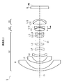
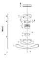
- FIG. 1 shows a first configuration example of a fisheye lens according to an embodiment of the present disclosure, and corresponds to the configuration of the first embodiment described later.
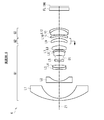
- FIG. 4 shows a second configuration example of the fisheye lens according to one embodiment, and corresponds to the configuration of the second embodiment described later.
- FIG. 7 shows a third configuration example of the fisheye lens according to the embodiment, and corresponds to the configuration of the third embodiment described later.
- FIG. 10 shows a fourth configuration example of the fisheye lens according to the embodiment, and corresponds to the configuration of the fourth embodiment described later.
- FIG. 13 shows a fifth configuration example of the fisheye lens according to the embodiment, and corresponds to the configuration of the fifth embodiment described later.
- FIG. 1 shows a first configuration example of a fisheye lens according to an embodiment of the present disclosure, and corresponds to the configuration of the first embodiment described later.
- FIG. 4 shows a second configuration example of the fisheye lens according to one embodiment, and corresponds to the configuration of the second embodiment described later.
- FIG. 7 shows a
- FIG. 16 shows a sixth configuration example of the fisheye lens according to the embodiment, and corresponds to the configuration of the sixth embodiment described later.
- FIG. 19 shows a seventh configuration example of the fisheye lens according to the embodiment, and corresponds to the configuration of the seventh embodiment described later.
- FIG. 22 shows an eighth configuration example of the fisheye lens according to the embodiment, and corresponds to the configuration of the eighth embodiment described later.
- FIG. 25 shows a ninth configuration example of the fisheye lens according to the embodiment, and corresponds to the configuration of the ninth embodiment described later.
- Z1 indicates an optical axis.
- An optical member FL such as a cover glass for protecting the image pickup device may be arranged between the fisheye lenses 1 to 9 according to the first to ninth configuration examples and the image plane IMG. Further, in addition to the cover glass, various optical filters such as a low-pass filter and an infrared cut filter may be arranged as the optical member FL.
- the fisheye lens according to the embodiment has a first lens group G1 having a refractive power, an intermediate group having a refractive power, and a refractive power in order from the object side to the image plane side along the optical axis Z1. It has a rear group.
- the first lens group G1 includes the first lens L1 and the second lens L2 in order from the object side to the image plane side.
- the intermediate group includes at least the second lens group G2.
- the intermediate group consists only of the second lens group G2.
- the intermediate group consists of a second lens group G2, a third lens group G3, and a fourth lens group G4.
- the rear group includes a first configuration example (Example 1) to a fourth configuration example (Example 4), and a sixth configuration example (Example 6) to a ninth configuration example (implementation).
- Example 9 it consists only of the third lens group G3.
- the fifth configuration example (Example 5) only the fifth lens group G5 is composed.
- the first lens group G1 and the rear group are fixed, and at least the second lens group G2 in the intermediate group is oriented in the optical axis direction. It is designed to focus by moving.
- the second lens group G2 is the focus group.
- the second lens group G2 and the fourth lens group G4 are set as the focus group.
- FIG. 1 and the like show the lens arrangement at infinity in focus.
- the moving direction of the focus group when focusing from infinity to a short distance is indicated by an arrow.
- the fisheye lens according to the embodiment further satisfies the predetermined conditional expression and the like described later.
- the configuration of each group is optimized, so that it is compact, lightweight, and an inner focusing method. It is possible to realize a fisheye lens and an image pickup device that are suitable for moving images with little change in the angle of view during wobbling.
- fL1 Focal distance of the first lens
- L1 f Focal distance of the whole system
- TTL Distance on the optical axis from the apex of the surface of the first lens L1 on the object side to the image plane
- IMG Y Image height at the maximum angle of view
- R21 Radius of curvature of the lens surface on the object side of the second lens L2
- R22 Radius of curvature of the lens surface on the image surface side of the second lens L2 BF: Distance on the optical axis from the lens surface
- conditional expressions (1) to (4) By satisfying the conditional expressions (1) to (4), various aberrations can be corrected, and good performance can be ensured despite the small size.
- the refraction angle with respect to the light beam incident from the lens surface on the most object side becomes large, it becomes difficult to correct the off-axis aberration. Further, since the focal length of the first lens L1 becomes stronger, it becomes difficult to shorten the total lens length. On the other hand, when the lower limit of the conditional equation (1) is exceeded, the ratio between the focal length of the first lens L1 and the focal length of the entire system becomes small, and the sag amount on the lens surface of the first lens L1 on the image plane side becomes loose ( (Small), and the refraction angle with respect to the incident light beam becomes smaller, which makes it difficult to secure the angle of view.
- the above conditional expression (2) defines the shape of the second lens L2.
- the second lens L2 is preferably a meniscus lens having a convex lens surface on the object side.
- conditional expression (2) it is more desirable to set the numerical range of the conditional expression (2) as in the following conditional expression (2A). 0.20 ⁇ (R21-R22) / (R21 + R22) ⁇ 1.00 ...... (2A)
- the distance on the optical axis from the lens surface on the image plane side to the image plane IMG and the distance on the optical axis from the apex of the surface on the object side of the first lens L1 to the image plane IMG Specifies the ratio of.
- good performance can be ensured in spite of its small size.
- the distance on the optical axis from the lens surface on the image plane side to the image plane IMG and the optical axis from the apex of the surface on the object side of the first lens L1 to the image plane IMG is exceeded, the distance on the optical axis from the lens surface on the image plane side to the image plane IMG and the optical axis from the apex of the surface on the object side of the first lens L1 to the image plane IMG.
- the ratio to the distance of is large, and it is necessary to secure a large back focus.
- conditional expression (3) In order to better realize the effect of the above-mentioned conditional expression (3), it is more desirable to set the numerical range of the conditional expression (3) as in the following conditional expression (3A). 0.17 ⁇ BF / TTL ⁇ 0.22 & (3A)
- conditional expression (4) it is more desirable to set the numerical range of the conditional expression (4) as in the following conditional expression (4A). 0.90 ⁇ Y / Y' ⁇ 1.13 .... (4A)
- R11 Radius of curvature of the lens surface on the object side of the first lens L1
- R12 Radius of curvature of the lens surface on the image surface side of the first lens L1.
- the conditional expression (5) defines the shape of the first lens L1. By satisfying the conditional expression (5), various aberrations can be corrected while securing a predetermined angle of view, and good performance can be ensured despite the small size. If the upper limit of the conditional expression (5) is exceeded, the power on the image plane side of the first lens L1 becomes tight (large), and it becomes difficult to correct off-axis astigmatism and curvature of field. When the lower limit of the conditional expression (5) is exceeded, the power of the first lens L1 becomes loose (small) and the refraction angle with respect to the incident light ray becomes small, which makes it difficult to secure the angle of view.
- the fisheye lens according to the embodiment satisfies the following conditional expression (6). 1.64 ⁇ nL1 ⁇ 1.93 ?? (6)
- nL1 The refractive index of the first lens L1.
- the conditional expression (6) defines the refractive index of the first lens L1. If the upper limit of the conditional expression (6) is exceeded, the refractive index of the first lens L1 becomes high and the specific gravity of the lens becomes heavy, which is not suitable for weight reduction. When the lower limit of the conditional equation (6) is exceeded, the refractive index of the first lens L1 becomes low and the specific gravity of the lens becomes light, but since the necessary and sufficient refractive index cannot be secured, the focal length of the first lens L1 is increased. There is a need. Therefore, it is difficult to shorten the total length.
- the fisheye lens according to the embodiment satisfies the following conditional expression (7). 3.0 ⁇ f2
- f Focal length of the whole system
- f2 Focal length of the second lens group G2.
- the conditional expression (7) defines the ratio between the focal length of the second lens group G2 and the focal length of the entire system.
- the ratio between the focal length of the second lens group G2 and the focal length of the entire system becomes large, and the focal length of the second lens group G2 becomes weak (long), so that aberration fluctuations occur.
- the amount of movement is large and it is difficult to shorten the total length.
- the ratio between the focal length of the second lens group G2 and the focal length of the entire system becomes small, and the focal length of the second lens group G2 becomes strong (short), so that the amount of movement is large. Is small, which is advantageous for shortening the total length, but the aberration fluctuation becomes large. In particular, it becomes difficult to correct off-axis aberrations.
- conditional expression (7) it is more desirable to set the numerical range of the conditional expression (7) as in the following conditional expression (7A). 3.14 ⁇
- / f ⁇ 18.03 > (7A)
- the fisheye lens according to the embodiment has an aperture stop St in the first lens group G1.
- the aperture aperture St is arranged in front of the fixed group (lenses L6, L7, L8) having a positive refractive power in the first lens group G1.
- the fisheye lens according to the embodiment may have an aperture stop St in the middle group.
- the fixed group (lenses L7, L8, L9) having a positive refractive power
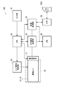
- FIG. 28 shows an example of the configuration of the image pickup apparatus 100 to which the fisheye lens according to the embodiment is applied.
- the image pickup device 100 is, for example, a digital still camera, and includes a camera block 10, a camera signal processing unit 20, an image processing unit 30, an LCD (Liquid Crystal Display) 40, and an R / W (reader / writer) 50. , CPU (Central Processing Unit) 60, an input unit 70, and a lens drive control unit 80.
- CPU Central Processing Unit
- the camera block 10 is responsible for an image pickup function, and has an image pickup lens 11 and an image pickup element 12 such as a CCD (Charge Coupled Devices) or a CMOS (Complementary Metal Oxide Semiconductor).
- the image pickup element 12 converts the optical image formed by the image pickup lens 11 into an electric signal, thereby outputting an image pickup signal (image signal) corresponding to the optical image.
- the fisheye lenses 1 to 9 according to each configuration example shown in FIG. 1 and the like can be applied.
- the camera signal processing unit 20 performs various signal processing such as analog-to-digital conversion, noise removal, image quality correction, and conversion to a brightness / color difference signal for the image signal output from the image pickup element 12.
- the image processing unit 30 performs recording / reproduction processing of an image signal, and performs compression coding / decompression decoding processing of an image signal based on a predetermined image data format, conversion processing of data specifications such as resolution, and the like. It has become.
- the LCD 40 has a function of displaying various data such as an operation state for the user's input unit 70 and a captured image.
- the R / W 50 writes the image data encoded by the image processing unit 30 to the memory card 1000 and reads out the image data recorded on the memory card 1000.
- the memory card 1000 is, for example, a semiconductor memory that can be attached to and detached from a slot connected to the R / W 50.
- the CPU 60 functions as a control processing unit that controls each circuit block provided in the image pickup apparatus 100, and controls each circuit block based on an instruction input signal or the like from the input unit 70.
- the input unit 70 includes various switches and the like on which a required operation is performed by the user.
- the input unit 70 is composed of, for example, a shutter release button for performing a shutter operation, a selection switch for selecting an operation mode, and the like, and outputs an instruction input signal according to the operation by the user to the CPU 60.
- the lens drive control unit 80 controls the drive of the lens arranged in the camera block 10, and controls a motor (not shown) that drives each lens of the image pickup lens 11 based on a control signal from the CPU 60. It has become.
- the image signal shot in the camera block 10 is output to the LCD 40 via the camera signal processing unit 20 and displayed as a camera-through image under the control of the CPU 60. Further, for example, when an instruction input signal for zooming or focusing is input from the input unit 70, the CPU 60 outputs a control signal to the lens drive control unit 80, and the image pickup lens 11 is controlled by the lens drive control unit 80. The predetermined lens moves.
- the captured image signal is output from the camera signal processing unit 20 to the image processing unit 30 and subjected to compression coding processing to obtain a predetermined image signal. Converted to digital data in data format. The converted data is output to the R / W 50 and written to the memory card 1000.
- the lens drive control unit 80 is based on a control signal from the CPU 60. This is done by moving a predetermined lens of the image pickup lens 11.
- the R / W 50 When reproducing the image data recorded on the memory card 1000, the R / W 50 reads out the predetermined image data from the memory card 1000 in response to the operation on the input unit 70, and the image processing unit 30 decompresses and decodes the predetermined image data. After the processing is performed, the reproduced image signal is output to the LCD 40 and the reproduced image is displayed.
- the image pickup device is applied to a digital still camera or the like, but the application range of the image pickup device is not limited to the digital still camera and is applied to various other image pickup devices. It is possible. For example, it can be applied to a digital single-lens reflex camera, a digital non-reflex camera, a digital video camera, a surveillance camera, and the like. Further, it can be widely applied as a camera unit of a digital input / output device such as a mobile phone having a built-in camera or an information terminal having a built-in camera. It can also be applied to interchangeable lens cameras.
- Si indicates the number of the i-th surface, which is coded so as to gradually increase from the object side.
- Ri indicates the value (mm) of the radius of curvature of the paraxial axis of the i-th plane.
- Di indicates the value (mm) of the distance on the optical axis between the i-th surface and the i + 1-th surface.
- Ndi indicates the value of the refractive index with respect to the d-line (wavelength 587.6 nm) of the material of the optical element having the i-th plane.
- ⁇ di indicates the value of the Abbe number in the d-line of the material of the optical element having the i-th plane.
- the part where the value of "ri” is “ ⁇ ” indicates a plane, a diaphragm surface, or the like.
- ASP in the column of the surface number (Si) indicates that the surface is formed of an aspherical shape.
- STO in the surface number column indicates that the aperture stop St is arranged at the corresponding position.
- OBJ in the column of the surface number indicates that the surface is an object surface (subject surface).
- IMG in the surface number column indicates that the surface is an image surface.
- F indicates the focal length of the entire system (unit: mm).
- “Fno” indicates an open F value (F number).
- ⁇ indicates a half angle of view (unit: °).
- Y indicates the image height (unit: mm).
- L indicates the total optical length (distance on the optical axis from the surface closest to the object to the image plane IMG) (unit: mm).
- some lenses used in each embodiment have a lens surface formed of an aspherical surface.
- the aspherical shape is defined by the following equation.
- "Ei” represents an exponential notation with a base of 10, that is, “10- i ", and for example, "0.12345E-05” is “0.12345E-05". It represents "0.12345 x 10⁻⁵".
- [Table 1] shows the basic lens data of the fisheye lens 1 according to the first embodiment shown in FIG.
- [Table 2] shows the values of the coefficients representing the shape of the aspherical surface in the fisheye lens 1 according to the first embodiment.
- [Table 3] shows the values of the focal length f, the F value, the total angle of view 2 ⁇ , the image height Y, and the optical total length L of the whole system in the fisheye lens 1 according to the first embodiment.
- [Table 4] shows the data of the plane spacing which is variable at the time of focusing in the fisheye lens 1 according to the first embodiment.
- [Table 5] shows the start surface and focal length (unit: mm) of each group of the fisheye lens 1 according to the first embodiment.
- a first lens group G1 having a positive refractive power, a second lens group G2 having a negative refractive power, and a third lens group G3 having a positive refractive power are objects. They are arranged in order from the side to the image plane side.
- the second lens group G2 corresponds to the intermediate group
- the third lens group G3 corresponds to the rear group.
- the first lens L1 to the eighth lens L8 are arranged in order from the object side to the image plane side.
- the first lens L1 is a meniscus-shaped negative lens with a convex surface facing the object side.
- the second lens L2 is a meniscus-shaped negative lens with a convex surface facing the object side.
- the third lens L3 is a meniscus-shaped negative lens with a convex surface facing the object side.
- the fourth lens L4 is a meniscus-shaped negative lens with a concave surface facing the object side.
- the fifth lens L5 is a biconvex positive lens.
- the sixth lens L6 and the seventh lens L7 constitute a bonded lens bonded to each other.
- the sixth lens L6 is a biconvex positive lens.
- the seventh lens L7 is a meniscus-shaped negative lens with a concave surface facing the object side.
- the eighth lens L8 is a biconvex positive lens.
- the ninth lens L9 and the tenth lens L10 are arranged in order from the object side to the image plane side.
- the ninth lens L9 is a biconvex positive lens.
- the tenth lens L10 is a negative lens having a biconcave shape.
- the eleventh lens L11 and the twelfth lens L12 are arranged in order from the object side to the image plane side.
- the eleventh lens L11 is a meniscus-shaped positive lens with a concave surface facing the object side.
- the twelfth lens L12 is a meniscus-shaped negative lens with a concave surface facing the object side.
- the eleventh lens L11 and the twelfth lens L12 constitute a bonded lens bonded to each other.
- An optical member FL such as a filter FL is arranged between the third lens group G3 and the image plane IMG.
- the aperture stop St is arranged in the first lens group G and is fixed to the image plane IMG.
- the second lens group G2 moves in the optical axis direction toward the image plane side as a focus group.
- the surface distance d16 between the first lens group G1 and the second lens group G2, and the second lens group G2 and the third lens group G3 changes.
- [Table 4] shows the values of the surface spacing at the variable infinity and the nearest time.
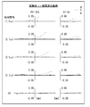
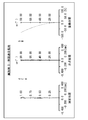
- FIG. 2 shows the longitudinal aberration of the fisheye lens 1 according to the first embodiment at infinity focusing.
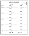
- FIG. 3 shows the lateral aberration of the fisheye lens 1 according to the first embodiment at infinity focusing.
- FIG. 2 shows spherical aberration, astigmatism (curvature of field), and distortion as longitudinal aberrations.
- the solid line shows the value at the d line (587.56 nm)
- the alternate long and short dash line shows the value at the g line (435.84 nm)
- the broken line shows the value at the C line (656.27 nm).
- S indicates a value in the sagittal image plane
- M indicates a value in the meridional image plane.
- the distortion diagram shows the values on the d-line.
- ⁇ indicates a half angle of view. The same applies to the aberration diagrams in the other examples thereafter.
- the fisheye lens 1 according to the first embodiment has various aberrations satisfactorily corrected and has excellent imaging performance.
- [Table 6] shows the basic lens data of the fisheye lens 2 according to the second embodiment shown in FIG.
- [Table 7] shows the values of the coefficients representing the shape of the aspherical surface in the fisheye lens 2 according to the second embodiment.
- [Table 8] shows the values of the focal length f, the F value, the total angle of view 2 ⁇ , the image height Y, and the optical total length L of the whole system in the fisheye lens 2 according to the second embodiment.
- [Table 9] shows the data of the plane spacing that becomes variable during focusing in the fisheye lens 2 according to the second embodiment.
- [Table 10] shows the starting surface and the focal length (unit: mm) of each group of the fisheye lens 2 according to the second embodiment.
- the first lens group G1 having a positive refractive power, the second lens group G2 having a negative refractive power, and the third lens group G3 having a positive refractive power are objects. They are arranged in order from the side to the image plane side.
- the second lens group G2 corresponds to the intermediate group
- the third lens group G3 corresponds to the rear group.
- the first lens L1 to the eighth lens L8 are arranged in order from the object side to the image plane side.
- the first lens L1 is a meniscus-shaped negative lens with a convex surface facing the object side.
- the second lens L2 is a meniscus-shaped negative lens with a convex surface facing the object side.
- the third lens L3 is a meniscus-shaped negative lens with a convex surface facing the object side.
- the fourth lens L4 is a meniscus-shaped negative lens with a concave surface facing the object side.
- the fifth lens L5 is a biconvex positive lens.
- the sixth lens L6 and the seventh lens L7 constitute a bonded lens bonded to each other.
- the sixth lens L6 is a biconvex positive lens.
- the seventh lens L7 is a meniscus-shaped negative lens with a concave surface facing the object side.
- the eighth lens L8 is a meniscus-shaped positive lens with a concave surface facing the object side.
- the ninth lens L9 and the tenth lens L10 are arranged in order from the object side to the image plane side.
- the ninth lens L9 is a biconvex positive lens.
- the tenth lens L10 is a negative lens having a biconcave shape.
- the eleventh lens L11 and the twelfth lens L12 are arranged in order from the object side to the image plane side.
- the eleventh lens L11 is a meniscus-shaped positive lens with a concave surface facing the object side.
- the twelfth lens L12 is a meniscus-shaped negative lens with a concave surface facing the object side.
- the eleventh lens L11 and the twelfth lens L12 constitute a bonded lens bonded to each other.
- a filter FL is arranged between the third lens group G3 and the image plane IMG.
- the aperture diaphragm S is arranged between the first lens group G1 and is fixed to the image plane IMG.
- An optical member FL such as a filter FL is arranged between the third lens group G3 and the image plane IMG.
- the aperture stop St is arranged in the first lens group G and is fixed to the image plane IMG.
- the second lens group G2 moves in the optical axis direction toward the image plane side as a focus group.
- the surface distance d16 between the first lens group G1 and the second lens group G2, and the second lens group G2 and the third lens group G3 changes.
- [Table 9] shows the values of the surface spacing at the variable infinity and the nearest time.
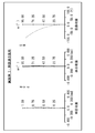
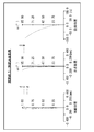
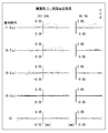
- FIG. 5 shows the longitudinal aberration of the fisheye lens 2 according to the second embodiment at infinity focusing.
- FIG. 6 shows the lateral aberration of the fisheye lens 2 according to the second embodiment at infinity focusing.
- the fisheye lens 2 according to the second embodiment has various aberrations satisfactorily corrected and has excellent imaging performance.
- [Table 11] shows the basic lens data of the fisheye lens 3 according to the third embodiment shown in FIG. 7.
- [Table 12] shows the values of the coefficients representing the shape of the aspherical surface in the fisheye lens 3 according to the third embodiment.
- [Table 13] shows the values of the focal length f, the F value, the total angle of view 2 ⁇ , the image height Y, and the optical total length L of the whole system in the fisheye lens 3 according to the third embodiment.
- [Table 14] shows the data of the plane spacing that becomes variable during focusing in the fisheye lens 3 according to the third embodiment.
- [Table 16] shows the start surface and focal length (unit: mm) of each group of the fisheye lens 3 according to the third embodiment.
- the first lens group G1 having a positive refractive power, the second lens group G2 having a negative refractive power, and the third lens group G3 having a positive refractive power are objects. They are arranged in order from the side to the image plane side.
- the second lens group G2 corresponds to the intermediate group
- the third lens group G3 corresponds to the rear group.
- the first lens L1 to the eighth lens L8 are arranged in order from the object side to the image plane side.
- the first lens L1 is a meniscus-shaped negative lens with a convex surface facing the object side.
- the second lens L2 is a meniscus-shaped negative lens with a convex surface facing the object side.
- the third lens L3 is a meniscus-shaped negative lens with a convex surface facing the object side.
- the fourth lens L4 is a meniscus-shaped negative lens with a concave surface facing the object side.
- the fifth lens L5 is a biconvex positive lens.
- the sixth lens L6 and the seventh lens L7 constitute a bonded lens bonded to each other.
- the sixth lens L6 is a biconvex positive lens.
- the seventh lens L7 is a meniscus-shaped negative lens with a concave surface facing the object side.
- the eighth lens L8 is a meniscus-shaped positive lens with a concave surface facing the object side.
- the ninth lens L9 and the tenth lens L10 are arranged in order from the object side to the image plane side.
- the ninth lens L9 is a biconvex positive lens.
- the tenth lens L10 is a negative lens having a biconcave shape.
- the eleventh lens L11 and the twelfth lens L12 are arranged in order from the object side to the image plane side.
- the eleventh lens L11 is a biconvex positive lens.
- the twelfth lens L12 is a meniscus-shaped negative lens with a concave surface facing the object side.
- the eleventh lens L11 and the twelfth lens L12 constitute a bonded lens bonded to each other.
- An optical member FL such as a filter FL is arranged between the third lens group G3 and the image plane IMG.
- the aperture stop St is arranged in the first lens group G and is fixed to the image plane IMG.
- the second lens group G2 moves in the optical axis direction as a focus group toward the image plane side.
- the surface distance d16 between the first lens group G1 and the second lens group G2, and the second lens group G2 and the third lens group G3 changes.
- [Table 14] shows the values of the surface spacing at the variable infinity and the nearest time.
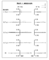
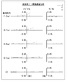
- FIG. 8 shows the longitudinal aberration of the fisheye lens 3 according to the third embodiment at infinity focusing.
- FIG. 9 shows the lateral aberration of the fisheye lens 3 according to the third embodiment at infinity focusing.
- the fisheye lens 3 according to the third embodiment has various aberrations satisfactorily corrected and has excellent imaging performance.
- [Table 16] shows the basic lens data of the fisheye lens 4 according to the fourth embodiment shown in FIG.
- [Table 17] shows the values of the coefficients representing the shape of the aspherical surface in the fisheye lens 4 according to the fourth embodiment.
- [Table 18] shows the values of the focal length f, the F value, the total angle of view 2 ⁇ , the image height Y, and the optical total length L of the whole system in the fisheye lens 4 according to the fourth embodiment.
- [Table 19] shows the data of the plane spacing that becomes variable during focusing in the fisheye lens 4 according to the fourth embodiment.
- [Table 20] shows the starting surface and the focal length (unit: mm) of each group of the fisheye lens 4 according to the fourth embodiment.
- the first lens group G1 having a positive refractive power, the second lens group G2 having a negative refractive power, and the third lens group G3 having a positive refractive power are objects. They are arranged in order from the side to the image plane side.
- the second lens group G2 corresponds to the intermediate group
- the third lens group G3 corresponds to the rear group.
- the first lens L1 to the eighth lens L8 are arranged in order from the object side to the image plane side.
- the first lens L1 is a meniscus-shaped negative lens with a convex surface facing the object side.
- the second lens L2 is a meniscus-shaped negative lens with a convex surface facing the object side.
- the third lens L3 is a negative lens having a biconcave shape.
- the fourth lens L4 is a meniscus-shaped negative lens with a concave surface facing the object side.
- the fifth lens L5 is a biconvex positive lens.
- the sixth lens L6 and the seventh lens L7 constitute a bonded lens bonded to each other.
- the sixth lens L6 is a biconvex positive lens.
- the seventh lens L7 is a meniscus-shaped negative lens with a concave surface facing the object side.
- the eighth lens L8 is a meniscus-shaped positive lens with a concave surface facing the object side.
- the ninth lens L9 and the tenth lens L10 are arranged in order from the object side to the image plane side.
- the ninth lens L9 is a biconvex positive lens.
- the tenth lens L10 is a negative lens having a biconcave shape.
- the eleventh lens L11 and the twelfth lens L12 are arranged in order from the object side to the image plane side.
- the eleventh lens L11 is a biconvex positive lens.
- the twelfth lens L12 is a meniscus-shaped negative lens with a concave surface facing the object side.
- the eleventh lens L11 and the twelfth lens L12 constitute a bonded lens bonded to each other.
- An optical member FL such as a filter FL is arranged between the third lens group G3 and the image plane IMG.
- the aperture stop St is arranged in the first lens group G and is fixed to the image plane IMG.
- the second lens group G2 moves in the optical axis direction toward the image plane side as a focus group.
- the surface distance d16 between the first lens group G1 and the second lens group G2, and the second lens group G2 and the third lens group G3 changes.
- [Table 19] shows the values of the surface spacing at the variable infinity and the nearest time.
- FIG. 11 shows the longitudinal aberration of the fisheye lens 4 according to the fourth embodiment at infinity focusing.
- FIG. 12 shows the lateral aberration of the fisheye lens 4 according to the fourth embodiment at infinity focusing.
- the fisheye lens 4 according to the fourth embodiment has various aberrations satisfactorily corrected and has excellent imaging performance.
- [Table 21] shows the basic lens data of the fisheye lens 5 according to the fifth embodiment shown in FIG.
- [Table 22] shows the values of the coefficients representing the shape of the aspherical surface in the fisheye lens 5 according to the fifth embodiment.
- [Table 23] shows the values of the focal length f, the F value, the total angle of view 2 ⁇ , the image height Y, and the optical total length L of the whole system in the fisheye lens 5 according to the fifth embodiment.
- [Table 24] shows the data of the plane spacing that becomes variable during focusing in the fisheye lens 5 according to the fifth embodiment.
- [Table 25] shows the start surface and focal length (unit: mm) of each group of the fisheye lens 5 according to the fifth embodiment.
- the fish-eye lens 5 according to the fifth embodiment has a first lens group G1 having a negative refractive power, a second lens group G2 having a positive refractive power, and a third lens group G3 having a positive refractive power.
- the fourth lens group G4 having a refractive power and the fifth lens group G5 having a negative power are arranged in order from the object side to the image plane side.
- the second lens group G2, the third lens group G3, and the fourth lens group G4 correspond to the intermediate group
- the fifth lens group G5 corresponds to the rear group.
- the first lens L1 to the fourth lens L4 are arranged in order from the object side to the image plane side.
- the first lens L1 is a meniscus-shaped negative lens with a convex surface facing the object side.
- the second lens L2 is a meniscus-shaped negative lens with a convex surface facing the object side.
- the third lens L3 is a negative lens having a biconcave shape.
- the fourth lens L4 is a biconvex positive lens.
- the second lens group G2 is composed of a fifth lens L5 which is a biconvex positive lens.
- the sixth lens L6 to the ninth lens L9 are arranged in order from the object side to the image plane side.
- the sixth lens L6 is a meniscus-shaped positive lens with a concave surface facing the object side.
- the seventh lens L7 is a biconvex positive lens.
- the eighth lens L8 is a negative lens having a biconcave shape.
- the seventh lens L7 and the eighth lens L8 constitute a bonded lens bonded to each other.
- the ninth lens L9 is a biconvex positive lens.
- the fourth lens group G4 is composed of a tenth lens L10 which is a biconvex positive lens.
- the eleventh lens L11 to the thirteenth lens L13 are arranged in order from the object side to the image plane side.
- the eleventh lens L11 is a negative lens having a biconcave shape.
- the twelfth lens L12 is a biconvex positive lens.
- the thirteenth lens L13 is a biconvex positive lens.
- An optical member FL such as a filter FL is arranged between the fifth lens group G5 and the image plane IMG.
- the aperture stop St is arranged in the third lens group G3 and is fixed to the image plane IMG.
- the second lens group G2 and the fourth lens group G4 move in the optical axis direction toward the object side as a focus group.
- the surface spacing d10, the surface spacing d18 between the third lens group G2 and the fourth lens group G4, and the surface spacing d20 between the fourth lens group G4 and the fifth lens group G5 vary.
- [Table 24] shows the values of the surface spacing at the variable infinity and the nearest time.
- FIG. 14 shows the longitudinal aberration of the fisheye lens 5 according to the fifth embodiment at infinity focusing.
- FIG. 15 shows the lateral aberration of the fisheye lens 5 according to the fifth embodiment at infinity focusing.
- the fisheye lens 5 according to the fifth embodiment has various aberrations satisfactorily corrected and has excellent imaging performance.
- [Table 26] shows the basic lens data of the fisheye lens 6 according to the sixth embodiment shown in FIG.
- [Table 27] shows the values of the coefficients representing the shape of the aspherical surface in the fisheye lens 6 according to the sixth embodiment.
- [Table 28] shows the values of the focal length f, the F value, the total angle of view 2 ⁇ , the image height Y, and the optical total length L of the whole system in the fisheye lens 6 according to the sixth embodiment.
- [Table 29] shows the data of the plane spacing that becomes variable during focusing in the fisheye lens 6 according to the sixth embodiment.
- [Table 20] shows the starting surface and the focal length (unit: mm) of each group of the fisheye lens 6 according to the sixth embodiment.
- the first lens group G1 having a positive refractive power, the second lens group G2 having a positive refractive power, and the third lens group G3 having a positive refractive power are objects. They are arranged in order from the side to the image plane side.
- the second lens group G2 corresponds to the intermediate group
- the third lens group G3 corresponds to the rear group.
- the first lens group G1 is formed by arranging the first lens L1 to the eighth lens L8 in order from the object side to the image plane side.
- the first lens L1 is a meniscus-shaped negative lens with a convex surface facing the object side.
- the second lens L2 is a negative lens having a biconcave shape.
- the third lens L3 is a meniscus-shaped negative lens with a convex surface facing the object side.
- the fourth lens L4 is a biconvex positive lens.
- the third lens L3 and the fourth lens L4 constitute a bonded lens bonded to each other.
- the fifth lens L5 is a negative lens having a biconcave shape.
- the sixth lens L6 is a biconvex positive lens.
- the seventh lens L7 is a meniscus-shaped negative lens with a concave surface facing the object side.
- the sixth lens L6 and the seventh lens L7 constitute a bonded lens bonded to each other.
- the eighth lens L8 is a meniscus-shaped positive lens with a concave surface facing the object side.
- the second lens group G2 is composed of a ninth lens L9, which is a meniscus-shaped positive lens with a concave surface facing the object side.
- the tenth lens L10 to the twelfth lens L12 are arranged in order from the object side to the image plane side.
- the tenth lens L10 is a meniscus-shaped negative lens with a concave surface facing the object side.
- the eleventh lens L11 is a biconvex positive lens.
- the twelfth lens L12 is a meniscus-shaped negative lens with a concave surface facing the object side.
- the eleventh lens L11 and the twelfth lens L12 constitute a bonded lens bonded to each other.
- An optical member FL such as a filter FL is arranged between the third lens group G3 and the image plane IMG.
- the aperture stop St is arranged in the first lens group G and is fixed to the image plane IMG.
- the second lens group G2 moves in the optical axis direction toward the object side as a focus group.
- the surface distance d15 between the first lens group G1 and the second lens group G2, and the second lens group G2 and the third lens group G3 The interplanar spacing d17 changes. [Table 29] shows the values of the surface spacing at the variable infinity and the nearest time.
- FIG. 17 shows the longitudinal aberration of the fisheye lens 6 according to the sixth embodiment at infinity focusing.
- FIG. 18 shows the lateral aberration of the fisheye lens 6 according to the sixth embodiment at infinity focusing.
- the fisheye lens 6 according to the sixth embodiment has various aberrations satisfactorily corrected and has excellent imaging performance.
- [Table 31] shows the basic lens data of the fisheye lens 7 according to the seventh embodiment shown in FIG.
- [Table 32] shows the values of the coefficients representing the shape of the aspherical surface in the fisheye lens 7 according to the seventh embodiment.
- [Table 33] shows the values of the focal length f, the F value, the total angle of view 2 ⁇ , the image height Y, and the optical total length L of the whole system in the fisheye lens 7 according to the seventh embodiment.
- [Table 34] shows the data of the plane spacing that becomes variable during focusing in the fisheye lens 7 according to the seventh embodiment.
- [Table 35] shows the starting surface and the focal length (unit: mm) of each group of the fisheye lens 7 according to the seventh embodiment.
- the first lens group G1 having a positive refractive power, the second lens group G2 having a negative refractive power, and the third lens group G3 having a positive refractive power are objects. They are arranged in order from the side to the image plane side.
- the second lens group G2 corresponds to the intermediate group
- the third lens group G3 corresponds to the rear group.
- the first lens group G1 is formed by arranging the first lens L1 to the eighth lens L8 in order from the object side to the image plane side.
- the first lens L1 is a meniscus-shaped negative lens with a convex surface facing the object side.
- the second lens L2 is a meniscus-shaped negative lens with a convex surface facing the object side.
- the third lens L3 is a meniscus-shaped negative lens with a convex surface facing the object side.
- the fourth lens L4 is a negative lens having a biconcave shape.
- the fifth lens L5 is a biconvex positive lens.
- the sixth lens L6 and the seventh lens L7 constitute a bonded lens bonded to each other.
- the sixth lens L6 is a biconvex positive lens.
- the seventh lens L7 is a meniscus-shaped negative lens with a concave surface facing the object side.
- the eighth lens L8 is a meniscus-shaped positive lens with a concave surface facing the object side.
- the ninth lens L9 and the tenth lens L10 are arranged in order from the object side to the image plane side.
- the ninth lens L9 is a biconvex positive lens.
- the tenth lens L10 is a negative lens having a biconcave shape.
- the eleventh lens L11 and the twelfth lens L12 are arranged in order from the object side to the image plane side.
- the eleventh lens L11 is a biconvex positive lens.
- the twelfth lens L12 is a meniscus-shaped negative lens with a concave surface facing the object side.
- the eleventh lens L11 and the twelfth lens L12 constitute a bonded lens bonded to each other.
- An optical member FL such as a filter FL is arranged between the third lens group G3 and the image plane IMG.
- the aperture stop St is arranged in the first lens group G and is fixed to the image plane IMG.
- the second lens group G2 moves in the optical axis direction toward the image plane side as a focus group.
- the surface distance d16 between the first lens group G1 and the second lens group G2, and the second lens group G2 and the third lens group G3 changes.
- [Table 34] shows the values of the surface spacing at the variable infinity and the nearest time.
- FIG. 20 shows the longitudinal aberration of the fisheye lens 7 according to the seventh embodiment at infinity focusing.
- FIG. 21 shows the lateral aberration of the fisheye lens 7 according to the seventh embodiment when the fisheye lens 7 is in focus at infinity.
- the fisheye lens 7 according to the seventh embodiment has various aberrations satisfactorily corrected and has excellent imaging performance.
- [Table 36] shows the basic lens data of the fisheye lens 8 according to the eighth embodiment shown in FIG.
- [Table 37] shows the values of the coefficients representing the shape of the aspherical surface in the fisheye lens 8 according to the eighth embodiment.
- [Table 38] shows the values of the focal length f, the F value, the total angle of view 2 ⁇ , the image height Y, and the optical total length L of the whole system in the fisheye lens 8 according to the eighth embodiment.
- [Table 39] shows the data of the plane spacing which becomes variable at the time of focusing in the fisheye lens 8 which concerns on Example 8.
- [Table 40] shows the start surface and focal length (unit: mm) of each group of the fisheye lens 8 according to the eighth embodiment.
- the first lens group G1 having a positive refractive power, the second lens group G2 having a positive refractive power, and the third lens group G3 having a negative refractive power are objects. They are arranged in order from the side to the image plane side.
- the second lens group G2 corresponds to the intermediate group
- the third lens group G3 corresponds to the rear group.
- the first lens L1 to the eighth lens L8 are arranged in order from the object side to the image plane side.
- the first lens L1 is a meniscus-shaped negative lens with a convex surface facing the object side.
- the second lens L2 is a meniscus-shaped negative lens with a convex surface facing the object side.
- the third lens L3 is a meniscus-shaped negative lens with a concave surface facing the object side.
- the fourth lens L4 is a meniscus-shaped positive lens with a concave surface facing the object side.
- the fifth lens L5 is a meniscus-shaped positive lens with a convex surface facing the object side.
- the sixth lens L6 is a meniscus-shaped positive lens with a concave surface facing the object side.
- the seventh lens L7 is a meniscus-shaped positive lens with a concave surface facing the object side.
- the eighth lens L8 is a meniscus-shaped negative lens with a concave surface facing the object side.
- the seventh lens L7 and the eighth lens L8 constitute a bonded lens bonded to each other.
- the ninth lens L9 and the tenth lens L10 are arranged in order from the object side to the image plane side.
- the ninth lens L9 is a meniscus-shaped negative lens with a concave surface facing the object side.
- the tenth lens L10 is a biconvex positive lens.
- the eleventh lens L11 to the thirteenth lens L13 are arranged in order from the object side to the image plane side.
- the eleventh lens L11 is a negative lens having a biconcave shape.
- the twelfth lens L12 is a biconvex positive lens.
- the eleventh lens L11 and the twelfth lens L12 constitute a bonded lens bonded to each other.
- the thirteenth lens L13 is a meniscus-shaped positive lens with a convex surface facing the object side.
- An optical member FL such as a filter FL is arranged between the third lens group G3 and the image plane IMG.
- the aperture stop St is arranged in the first lens group G and is fixed to the image plane IMG.
- the second lens group G2 moves in the optical axis direction toward the object side as a focus group.
- the surface distance d16 between the first lens group G1 and the second lens group G2, and the second lens group G2 and the third lens group G3 changes.
- [Table 39] shows the values of the surface spacing at the variable infinity and the nearest time.
- FIG. 23 shows the longitudinal aberration of the fisheye lens 8 according to the eighth embodiment at infinity focusing.
- FIG. 24 shows the lateral aberration of the fisheye lens 8 according to the eighth embodiment at infinity focusing.
- the fisheye lens 8 according to the eighth embodiment has various aberrations satisfactorily corrected and has excellent imaging performance.
- [Table 41] shows the basic lens data of the fisheye lens 9 according to the ninth embodiment shown in FIG. 25.
- [Table 42] shows the values of the coefficients representing the shape of the aspherical surface in the fisheye lens 9 according to the ninth embodiment.
- [Table 43] shows the values of the focal length f, the F value, the total angle of view 2 ⁇ , the image height Y, and the optical total length L of the whole system in the fisheye lens 9 according to the ninth embodiment.
- [Table 44] shows the data of the plane spacing which becomes variable at the time of focusing in the fisheye lens 9 which concerns on Example 9.
- [Table 45] shows the starting surface and the focal length (unit: mm) of each group of the fisheye lens 9 according to the ninth embodiment.
- the first lens group G1 having a positive refractive power, the second lens group G2 having a negative refractive power, and the third lens group G3 having a positive refractive power are objects. They are arranged in order from the side to the image plane side.
- the second lens group G2 corresponds to the intermediate group
- the third lens group G3 corresponds to the rear group.
- the first lens L1 to the eighth lens L8 are arranged in order from the object side to the image plane side.
- the first lens L1 is a meniscus-shaped negative lens with a convex surface facing the object side.
- the second lens L2 is a meniscus-shaped negative lens with a convex surface facing the object side.
- the third lens L3 is a meniscus-shaped negative lens with a convex surface facing the object side.
- the fourth lens L4 is a negative lens having a biconcave shape.
- the fifth lens L5 is a biconvex positive lens.
- the sixth lens L6 is a biconvex positive lens.
- the seventh lens L7 is a meniscus-shaped negative lens with a concave surface facing the object side.
- the sixth lens L6 and the seventh lens L7 constitute a bonded lens bonded to each other.
- the eighth lens L8 is a meniscus-shaped positive lens with a concave surface facing the object side.
- the ninth lens L9 and the tenth lens L10 are arranged in order from the object side to the image plane side.
- the ninth lens L9 is a biconvex positive lens.
- the tenth lens L10 is a negative lens having a biconcave shape.
- the eleventh lens L11 and the twelfth lens L12 are arranged in order from the object side to the image plane side.
- the eleventh lens L11 is a biconvex positive lens.
- the twelfth lens L12 is a meniscus-shaped negative lens with a concave surface facing the object side.
- the eleventh lens L11 and the twelfth lens L12 constitute a bonded lens bonded to each other.
- An optical member FL such as a filter FL is arranged between the third lens group G3 and the image plane IMG.
- the aperture stop St is arranged in the first lens group G and is fixed to the image plane IMG.
- the second lens group G2 moves in the optical axis direction toward the image plane side as a focus group.
- the surface distance d16 between the first lens group G1 and the second lens group G2, and the second lens group G2 and the third lens group G3 changes.
- [Table 44] shows the values of the surface spacing at the variable infinity and the nearest time.
- FIG. 26 shows the longitudinal aberration of the fisheye lens 9 according to the ninth embodiment at infinity focusing.
- FIG. 27 shows the lateral aberration of the fisheye lens 9 according to the ninth embodiment at infinity focusing.
- the fisheye lens 9 according to the ninth embodiment has various aberrations satisfactorily corrected and has excellent imaging performance.
- [Other numerical data of each embodiment] [Table 46] shows a summary of the values related to each of the above conditional expressions for each embodiment. As can be seen from [Table 46], the values of each embodiment are within the numerical range for each conditional expression.
- the technology according to the present disclosure can be applied to various products.
- the technology according to the present disclosure is any kind of movement such as an automobile, an electric vehicle, a hybrid electric vehicle, a motorcycle, a bicycle, a personal mobility, an airplane, a drone, a ship, a robot, a construction machine, and an agricultural machine (tractor). It may be realized as a device mounted on the body.
- FIG. 29 is a block diagram showing a schematic configuration example of a vehicle control system 7000, which is an example of a mobile control system to which the technique according to the present disclosure can be applied.
- the vehicle control system 7000 includes a plurality of electronic control units connected via a communication network 7010.
- the vehicle control system 7000 includes a drive system control unit 7100, a body system control unit 7200, a battery control unit 7300, an outside information detection unit 7400, an in-vehicle information detection unit 7500, and an integrated control unit 7600. ..
- the communication network 7010 connecting these plurality of control units conforms to any standard such as CAN (Controller Area Network), LIN (Local Interconnect Network), LAN (Local Area Network) or FlexRay (registered trademark). It may be an in-vehicle communication network.
- CAN Controller Area Network
- LIN Local Interconnect Network
- LAN Local Area Network
- FlexRay registered trademark
- Each control unit includes a microcomputer that performs arithmetic processing according to various programs, a storage unit that stores programs executed by the microcomputer or parameters used for various arithmetic, and a drive circuit that drives various controlled devices. To prepare for.
- Each control unit is provided with a network I / F for communicating with other control units via the communication network 7010, and is connected to devices or sensors inside or outside the vehicle by wired communication or wireless communication.
- a communication I / F for performing communication is provided. In FIG.
- control unit 7600 the microcomputer 7610, the general-purpose communication I / F7620, the dedicated communication I / F7630, the positioning unit 7640, the beacon receiving unit 7650, the in-vehicle device I / F7660, the audio image output unit 7670,
- vehicle-mounted network I / F 7680 and the storage unit 7690 are illustrated.
- Other control units also include a microcomputer, a communication I / F, a storage unit, and the like.
- the drive system control unit 7100 controls the operation of the device related to the drive system of the vehicle according to various programs.
- the drive system control unit 7100 has a driving force generator for generating the driving force of the vehicle such as an internal combustion engine or a driving motor, a driving force transmission mechanism for transmitting the driving force to the wheels, and a steering angle of the vehicle. It functions as a control device such as a steering mechanism for adjusting and a braking device for generating braking force of the vehicle.
- the drive system control unit 7100 may have a function as a control device such as ABS (Antilock Brake System) or ESC (Electronic Stability Control).
- the vehicle state detection unit 7110 is connected to the drive system control unit 7100.
- the vehicle state detection unit 7110 may include, for example, a gyro sensor that detects the angular velocity of the axial rotation motion of the vehicle body, an acceleration sensor that detects the acceleration of the vehicle, an accelerator pedal operation amount, a brake pedal operation amount, or steering wheel steering. It includes at least one of sensors for detecting an angle, engine speed, wheel speed, and the like.
- the drive system control unit 7100 performs arithmetic processing using a signal input from the vehicle state detection unit 7110, and controls an internal combustion engine, a drive motor, an electric power steering device, a brake device, and the like.
- the body system control unit 7200 controls the operation of various devices mounted on the vehicle body according to various programs.
- the body system control unit 7200 functions as a keyless entry system, a smart key system, a power window device, or a control device for various lamps such as headlamps, back lamps, brake lamps, turn signals or fog lamps.
- a radio wave transmitted from a portable device that substitutes for a key or signals of various switches may be input to the body system control unit 7200.
- the body system control unit 7200 receives inputs of these radio waves or signals and controls a vehicle door lock device, a power window device, a lamp, and the like.
- the battery control unit 7300 controls the secondary battery 7310, which is the power supply source of the drive motor, according to various programs. For example, information such as the battery temperature, the battery output voltage, or the remaining capacity of the battery is input to the battery control unit 7300 from the battery device including the secondary battery 7310. The battery control unit 7300 performs arithmetic processing using these signals, and controls the temperature control of the secondary battery 7310 or the cooling device provided in the battery device.
- the vehicle outside information detection unit 7400 detects information outside the vehicle equipped with the vehicle control system 7000.
- the image pickup unit 7410 and the vehicle exterior information detection unit 7420 is connected to the vehicle exterior information detection unit 7400.
- the image pickup unit 7410 includes at least one of a ToF (TimeOfFlight) camera, a stereo camera, a monocular camera, an infrared camera, and other cameras.
- the vehicle outside information detection unit 7420 is used, for example, to detect the current weather or an environment sensor for detecting the weather, or other vehicles, obstacles, pedestrians, etc. around the vehicle equipped with the vehicle control system 7000. At least one of the surrounding information detection sensors is included.
- the environment sensor may be, for example, at least one of a raindrop sensor that detects rainy weather, a fog sensor that detects fog, a sunshine sensor that detects the degree of sunshine, and a snow sensor that detects snowfall.
- the ambient information detection sensor may be at least one of an ultrasonic sensor, a radar device, and a LIDAR (Light Detection and Ringing, Laser Imaging Detection and Ringing) device.
- the image pickup unit 7410 and the vehicle exterior information detection unit 7420 may be provided as independent sensors or devices, or may be provided as a device in which a plurality of sensors or devices are integrated.
- FIG. 30 shows an example of the installation position of the image pickup unit 7410 and the vehicle outside information detection unit 7420.
- the image pickup unit 7910, 7912, 7914, 7916, 7918 are provided, for example, at at least one of the front nose, side mirror, rear bumper, back door, and upper part of the windshield of the vehicle interior of the vehicle 7900.
- the image pickup unit 7910 provided in the front nose and the image pickup section 7918 provided in the upper part of the windshield in the vehicle interior mainly acquire an image in front of the vehicle 7900.
- the image pickup units 7912 and 7914 provided in the side mirrors mainly acquire images of the side of the vehicle 7900.
- the image pickup unit 7916 provided in the rear bumper or the back door mainly acquires an image of the rear of the vehicle 7900.
- the image pickup unit 7918 provided on the upper part of the windshield in the vehicle interior is mainly used for detecting a preceding vehicle, a pedestrian, an obstacle, a traffic light, a traffic sign, a lane, or the like.
- FIG. 30 shows an example of the shooting range of each of the imaging units 7910, 7912, 7914, 7916.
- the imaging range a indicates the imaging range of the imaging unit 7910 provided on the front nose
- the imaging ranges b and c indicate the imaging range of the imaging units 7912 and 7914 provided on the side mirrors, respectively
- the imaging range d indicates the imaging range d.
- the imaging range of the imaging unit 7916 provided on the rear bumper or the back door is shown. For example, by superimposing the image data captured by the image pickup units 7910, 7912, 7914, 7916, a bird's-eye view image of the vehicle 7900 can be obtained.
- the vehicle exterior information detection unit 7920, 7922, 7924, 7926, 7928, 7930 provided at the front, rear, side, corner and the upper part of the windshield of the vehicle interior of the vehicle 7900 may be, for example, an ultrasonic sensor or a radar device.
- the vehicle exterior information detection units 7920, 7926, 7930 provided on the front nose, rear bumper, back door, and upper part of the windshield in the vehicle interior of the vehicle 7900 may be, for example, a lidar device.
- These out-of-vehicle information detection units 7920 to 7930 are mainly used for detecting a preceding vehicle, a pedestrian, an obstacle, or the like.
- the vehicle outside information detection unit 7400 causes the image pickup unit 7410 to capture an image of the outside of the vehicle and receives the captured image data. Further, the vehicle outside information detection unit 7400 receives detection information from the connected vehicle outside information detection unit 7420.
- the vehicle exterior information detection unit 7420 is an ultrasonic sensor, a radar device, or a lidar device
- the vehicle exterior information detection unit 7400 transmits ultrasonic waves, electromagnetic waves, or the like, and receives received reflected wave information.
- the out-of-vehicle information detection unit 7400 may perform object detection processing or distance detection processing such as a person, a vehicle, an obstacle, a sign, or a character on a road surface based on the received information.
- the out-of-vehicle information detection unit 7400 may perform an environment recognition process for recognizing rainfall, fog, road surface conditions, etc. based on the received information.
- the out-of-vehicle information detection unit 7400 may calculate the distance to an object outside the vehicle based on the received information.
- the vehicle outside information detection unit 7400 may perform image recognition processing or distance detection processing for recognizing a person, a vehicle, an obstacle, a sign, a character on the road surface, or the like based on the received image data.
- the vehicle outside information detection unit 7400 performs processing such as distortion correction or alignment on the received image data, and synthesizes image data captured by different image pickup units 7410 to generate a bird's-eye view image or a panoramic image. May be good.
- the vehicle exterior information detection unit 7400 may perform the viewpoint conversion process using the image data captured by different image pickup units 7410.
- the in-vehicle information detection unit 7500 detects the in-vehicle information.
- a driver state detection unit 7510 that detects the state of the driver is connected to the in-vehicle information detection unit 7500.
- the driver state detection unit 7510 may include a camera that captures the driver, a biosensor that detects the driver's biological information, a microphone that collects sound in the vehicle interior, and the like.
- the biosensor is provided on, for example, a seat surface or a steering wheel, and detects biometric information of a passenger sitting on the seat or a driver holding the steering wheel.
- the in-vehicle information detection unit 7500 may calculate the degree of fatigue or concentration of the driver based on the detection information input from the driver state detection unit 7510, and may determine whether the driver is asleep. You may.
- the in-vehicle information detection unit 7500 may perform processing such as noise canceling processing on the collected audio signal.
- the integrated control unit 7600 controls the overall operation in the vehicle control system 7000 according to various programs.
- An input unit 7800 is connected to the integrated control unit 7600.
- the input unit 7800 is realized by a device that can be input-operated by the passenger, such as a touch panel, a button, a microphone, a switch, or a lever. Data obtained by recognizing the voice input by the microphone may be input to the integrated control unit 7600.
- the input unit 7800 may be, for example, a remote control device using infrared rays or other radio waves, or an external connection device such as a mobile phone or a PDA (Personal Digital Assistant) corresponding to the operation of the vehicle control system 7000. You may.
- the input unit 7800 may be, for example, a camera, in which case the passenger can input information by gesture. Alternatively, data obtained by detecting the movement of the wearable device worn by the passenger may be input. Further, the input unit 7800 may include, for example, an input control circuit that generates an input signal based on the information input by the passenger or the like using the input unit 7800 and outputs the input signal to the integrated control unit 7600. By operating the input unit 7800, the passenger or the like inputs various data to the vehicle control system 7000 and instructs the processing operation.
- the storage unit 7690 may include a ROM (Read Only Memory) for storing various programs executed by the microcomputer, and a RAM (Random Access Memory) for storing various parameters, calculation results, sensor values, and the like. Further, the storage unit 7690 may be realized by a magnetic storage device such as an HDD (Hard Disc Drive), a semiconductor storage device, an optical storage device, an optical magnetic storage device, or the like.
- ROM Read Only Memory
- RAM Random Access Memory
- the general-purpose communication I / F 7620 is a general-purpose communication I / F that mediates communication with various devices existing in the external environment 7750.
- General-purpose communication I / F7620 is a cellular communication protocol such as GSM (registered trademark) (Global System of Mobile communications), WiMAX (registered trademark), LTE (registered trademark) (Long Term Evolution) or LTE-A (LTE-Advanced).
- GSM Global System of Mobile communications
- WiMAX registered trademark
- LTE registered trademark
- LTE-A Long Term Evolution-Advanced
- Bluetooth® may be implemented.
- the general-purpose communication I / F7620 connects to a device (for example, an application server or a control server) existing on an external network (for example, the Internet, a cloud network, or a business-specific network) via a base station or an access point, for example. You may. Further, the general-purpose communication I / F7620 uses, for example, P2P (Peer To Peer) technology to provide a terminal existing in the vicinity of the vehicle (for example, a driver, a pedestrian or a store terminal, or an MTC (Machine Type Communication) terminal). May be connected with.
- P2P Peer To Peer
- MTC Machine Type Communication
- the dedicated communication I / F 7630 is a communication I / F that supports a communication protocol formulated for use in a vehicle.
- the dedicated communication I / F7630 uses a standard protocol such as WAVE (Wireless Access in Vehicle Environment), DSRC (Dedicated Short Range Communications), which is a combination of the lower layer IEEE802.11p and the upper layer IEEE1609, or a cellular communication protocol. May be implemented.
- Dedicated communication I / F7630 is typically vehicle-to-vehicle (Vehicle to Vehicle) communication, road-to-vehicle (Vehicle to Infrastructure) communication, vehicle-to-home (Vehicle to Home) communication, and pedestrian-to-vehicle (Vehicle to Pedestrian) communication. ) Carry out V2X communication, a concept that includes one or more of the communications.
- the positioning unit 7640 receives, for example, a GNSS signal from a GNSS (Global Navigation Satellite System) satellite (for example, a GPS signal from a GPS (Global Positioning System) satellite) and executes positioning, and performs positioning, and the latitude, longitude, and altitude of the vehicle. Generate location information including.
- the positioning unit 7640 may specify the current position by exchanging signals with the wireless access point, or may acquire position information from a terminal such as a mobile phone, PHS, or smartphone having a positioning function.
- the beacon receiving unit 7650 receives radio waves or electromagnetic waves transmitted from a radio station or the like installed on the road, and acquires information such as the current position, traffic jam, road closure, or required time.
- the function of the beacon receiving unit 7650 may be included in the above-mentioned dedicated communication I / F 7630.
- the in-vehicle device I / F 7660 is a communication interface that mediates the connection between the microcomputer 7610 and various in-vehicle devices 7760 existing in the vehicle.
- the in-vehicle device I / F7660 may establish a wireless connection using a wireless communication protocol such as wireless LAN, Bluetooth (registered trademark), NFC (Near Field Communication) or WUSB (Wireless USB).
- a wireless communication protocol such as wireless LAN, Bluetooth (registered trademark), NFC (Near Field Communication) or WUSB (Wireless USB).
- the in-vehicle device I / F7660 can be connected to USB (Universal Serial Bus), HDMI (registered trademark) (High-Definition Multimedia Interface), or MHL (Mobile) via a connection terminal (and a cable if necessary) (not shown).
- a wired connection such as High-definition Link may be established.
- the in-vehicle device 7760 may include, for example, at least one of a passenger's mobile device or wearable device, or information device carried in or attached to the vehicle. Further, the in-vehicle device 7760 may include a navigation device that searches for a route to an arbitrary destination.
- the in-vehicle device I / F 7660 exchanges control signals or data signals with these in-vehicle devices 7760.
- the in-vehicle network I / F7680 is an interface that mediates communication between the microcomputer 7610 and the communication network 7010.
- the vehicle-mounted network I / F7680 transmits / receives signals and the like according to a predetermined protocol supported by the communication network 7010.
- the microcomputer 7610 of the integrated control unit 7600 is via at least one of general-purpose communication I / F7620, dedicated communication I / F7630, positioning unit 7640, beacon receiving unit 7650, in-vehicle device I / F7660, and in-vehicle network I / F7680.
- the vehicle control system 7000 is controlled according to various programs based on the information acquired. For example, the microcomputer 7610 calculates the control target value of the driving force generator, the steering mechanism, or the braking device based on the acquired information inside and outside the vehicle, and outputs a control command to the drive system control unit 7100. May be good.
- the microcomputer 7610 realizes ADAS (Advanced Driver Assistance System) functions including vehicle collision avoidance or impact mitigation, follow-up driving based on inter-vehicle distance, vehicle speed maintenance driving, vehicle collision warning, vehicle lane deviation warning, and the like. Cooperative control may be performed for the purpose of.
- the microcomputer 7610 automatically travels autonomously without relying on the driver's operation by controlling the driving force generator, steering mechanism, braking device, etc. based on the acquired information on the surroundings of the vehicle. Coordinated control may be performed for the purpose of driving or the like.
- the microcomputer 7610 has information acquired via at least one of a general-purpose communication I / F7620, a dedicated communication I / F7630, a positioning unit 7640, a beacon receiving unit 7650, an in-vehicle device I / F7660, and an in-vehicle network I / F7680. Based on the above, three-dimensional distance information between the vehicle and an object such as a surrounding structure or a person may be generated, and local map information including the peripheral information of the current position of the vehicle may be created. Further, the microcomputer 7610 may predict the danger of a vehicle collision, a pedestrian or the like approaching or entering a closed road, and generate a warning signal based on the acquired information.
- the warning signal may be, for example, a signal for generating a warning sound or lighting a warning lamp.
- the audio image output unit 7670 transmits an output signal of at least one of audio and image to an output device capable of visually or audibly notifying information to the passenger or the outside of the vehicle.
- an audio speaker 7710, a display unit 7720, and an instrument panel 7730 are exemplified as output devices.
- the display unit 7720 may include, for example, at least one of an onboard display and a head-up display.
- the display unit 7720 may have an AR (Augmented Reality) display function.
- the output device may be other devices such as headphones, wearable devices such as eyeglass-type displays worn by passengers, projectors or lamps other than these devices.
- the display device displays the results obtained by various processes performed by the microcomputer 7610 or the information received from other control units in various formats such as texts, images, tables, and graphs. Display visually.
- the audio output device converts an audio signal composed of reproduced audio data, acoustic data, or the like into an analog signal and outputs the audio signal audibly.
- At least two control units connected via the communication network 7010 may be integrated as one control unit.
- each control unit may be composed of a plurality of control units.
- the vehicle control system 7000 may include another control unit (not shown).
- the other control unit may have a part or all of the functions carried out by any of the control units. That is, as long as information is transmitted and received via the communication network 7010, predetermined arithmetic processing may be performed by any of the control units.
- a sensor or device connected to any control unit may be connected to another control unit, and a plurality of control units may send and receive detection information to and from each other via the communication network 7010. .
- the fisheye lens and the image pickup apparatus of the present disclosure can be applied to the image pickup unit 7410 and the image pickup unit 7910, 7912, 7914, 7916, 7918.
- the technique according to the present disclosure may be applied to an endoscopic surgery system.
- FIG. 31 is a diagram showing an example of a schematic configuration of an endoscopic surgery system 5000 to which the technique according to the present disclosure can be applied.
- FIG. 31 illustrates a surgeon (doctor) 5067 performing surgery on patient 5071 on patient bed 5069 using the endoscopic surgery system 5000.
- the endoscopic surgery system 5000 includes an endoscope 5001, other surgical tools 5017, a support arm device 5027 for supporting the endoscope 5001, and various devices for endoscopic surgery. It is composed of a cart 5037 and a cart 5037.
- trocca 5025a to 5025d In endoscopic surgery, instead of cutting and opening the abdominal wall, multiple tubular laparotomy instruments called trocca 5025a to 5025d are punctured into the abdominal wall. Then, from the trocca 5025a to 5025d, the lens barrel 5003 of the endoscope 5001 and other surgical tools 5017 are inserted into the body cavity of the patient 5071.
- other surgical tools 5017 a pneumoperitoneum tube 5019, an energy treatment tool 5021 and forceps 5023 are inserted into the body cavity of patient 5071.
- the energy treatment tool 5021 is a treatment tool for incising and peeling a tissue, sealing a blood vessel, or the like by using a high frequency current or ultrasonic vibration.
- the surgical tool 5017 shown in the illustration is merely an example, and as the surgical tool 5017, various surgical tools generally used in endoscopic surgery such as a sword and a retractor may be used.
- the image of the surgical site in the body cavity of the patient 5071 taken by the endoscope 5001 is displayed on the display device 5041.
- the surgeon 5067 performs a procedure such as excising the affected area by using the energy treatment tool 5021 or the forceps 5023 while viewing the image of the surgical site displayed on the display device 5041 in real time.
- the pneumoperitoneum tube 5019, the energy treatment tool 5021, and the forceps 5023 are supported by the operator 5067, an assistant, or the like during the operation.
- the support arm device 5027 includes an arm portion 5031 extending from the base portion 5029.
- the arm portion 5031 is composed of joint portions 5033a, 5033b, 5033c, and links 5035a, 5035b, and is driven by control from the arm control device 5045.
- the endoscope 5001 is supported by the arm portion 5031, and its position and posture are controlled. Thereby, the stable position fixing of the endoscope 5001 can be realized.
- the endoscope 5001 is composed of a lens barrel 5003 in which a region having a predetermined length from the tip is inserted into the body cavity of the patient 5071, and a camera head 5005 connected to the base end of the lens barrel 5003.
- the endoscope 5001 configured as a so-called rigid mirror having a rigid barrel 5003 is illustrated, but the endoscope 5001 is configured as a so-called flexible mirror having a flexible barrel 5003. May be good.
- An opening in which an objective lens is fitted is provided at the tip of the lens barrel 5003.
- a light source device 5043 is connected to the endoscope 5001, and the light generated by the light source device 5043 is guided to the tip of the lens barrel by a light guide extending inside the lens barrel 5003, and is an objective. It is irradiated toward the observation target in the body cavity of the patient 5071 through the lens.
- the endoscope 5001 may be a direct endoscope, a perspective mirror, or a side endoscope.
- An optical system and an image pickup element are provided inside the camera head 5005, and the reflected light (observation light) from the observation target is focused on the image pickup element by the optical system.
- the observation light is photoelectrically converted by the image pickup device, and an electric signal corresponding to the observation light, that is, an image signal corresponding to the observation image is generated.
- the image signal is transmitted to the camera control unit (CCU: Camera Control Unit) 5039 as RAW data.
- the camera head 5005 is equipped with a function of adjusting the magnification and the focal length by appropriately driving the optical system thereof.
- the camera head 5005 may be provided with a plurality of image pickup elements.
- a plurality of relay optical systems are provided inside the lens barrel 5003 in order to guide the observation light to each of the plurality of image pickup elements.
- the CCU 5039 is composed of a CPU (Central Processing Unit), a GPU (Graphics Processing Unit), and the like, and comprehensively controls the operations of the endoscope 5001 and the display device 5041. Specifically, the CCU 5039 performs various image processing for displaying an image based on the image signal, such as a development process (demosaic process), on the image signal received from the camera head 5005. The CCU 5039 provides the image signal subjected to the image processing to the display device 5041. Further, the CCU 5039 transmits a control signal to the camera head 5005 and controls the driving thereof.
- the control signal may include information about imaging conditions such as magnification and focal length.
- the display device 5041 displays an image based on the image signal processed by the CCU 5039 under the control of the CCU 5039.
- the endoscope 5001 is compatible with high-resolution shooting such as 4K (horizontal pixel number 3840 x vertical pixel number 2160) or 8K (horizontal pixel number 7680 x vertical pixel number 4320), and / or 3D display.
- the display device 5041 a display device capable of displaying a high resolution and / or a device capable of displaying in 3D can be used.
- a display device 5041 having a size of 55 inches or more is used for high-resolution shooting such as 4K or 8K, a further immersive feeling can be obtained.
- a plurality of display devices 5041 having different resolutions and sizes may be provided depending on the application.
- the light source device 5043 is composed of, for example, a light source such as an LED (light emission diode), and supplies irradiation light for photographing the surgical site to the endoscope 5001.
- a light source such as an LED (light emission diode)
- the arm control device 5045 is configured by a processor such as a CPU, and operates according to a predetermined program to control the drive of the arm portion 5031 of the support arm device 5027 according to a predetermined control method.
- the input device 5047 is an input interface for the endoscopic surgery system 5000.
- the user can input various information and input instructions to the endoscopic surgery system 5000 via the input device 5047.
- the user inputs various information related to the surgery, such as physical information of the patient and information about the surgical procedure, via the input device 5047.
- the user is instructed to drive the arm portion 5031 via the input device 5047, or is instructed to change the imaging conditions (type of irradiation light, magnification, focal length, etc.) by the endoscope 5001. , Instructions to drive the energy treatment tool 5021, etc. are input.
- the type of the input device 5047 is not limited, and the input device 5047 may be various known input devices.
- the input device 5047 for example, a mouse, a keyboard, a touch panel, a switch, a foot switch 5057 and / or a lever and the like can be applied.
- the touch panel may be provided on the display surface of the display device 5041.
- the input device 5047 is a device worn by the user, such as a glasses-type wearable device or an HMD (Head Mounted Display), and various inputs are made according to the user's gesture and line of sight detected by these devices. Is done. Further, the input device 5047 includes a camera capable of detecting the movement of the user, and various inputs are performed according to the gesture and the line of sight of the user detected from the image captured by the camera. Further, the input device 5047 includes a microphone capable of picking up the voice of the user, and various inputs are performed by voice via the microphone.
- a glasses-type wearable device or an HMD Head Mounted Display
- the input device 5047 is configured to be able to input various information in a non-contact manner, so that a user who belongs to a clean area (for example, an operator 5067) can operate a device belonging to the unclean area in a non-contact manner. Is possible. In addition, the user can operate the device without taking his / her hand off the surgical tool that he / she has, which improves the convenience of the user.
- a clean area for example, an operator 5067
- the treatment tool control device 5049 controls the drive of the energy treatment tool 5021 for cauterizing tissue, incising, sealing a blood vessel, or the like.
- the pneumoperitoneum device 5051 gas in the body cavity through the pneumoperitoneum tube 5019 in order to inflate the body cavity of the patient 5071 for the purpose of securing the field of view by the endoscope 5001 and securing the work space of the operator. Is sent.
- the recorder 5053 is a device capable of recording various information related to surgery.
- the printer 5055 is a device capable of printing various information related to surgery in various formats such as text, images, and graphs.
- the support arm device 5027 includes a base portion 5029 as a base and an arm portion 5031 extending from the base portion 5029.
- the arm portion 5031 is composed of a plurality of joint portions 5033a, 5033b, 5033c and a plurality of links 5035a, 5035b connected by the joint portions 5033b, but in FIG. 31, for the sake of simplicity.
- the configuration of the arm portion 5031 is simplified and illustrated. Actually, the shapes, numbers and arrangements of the joint portions 5033a to 5033c and the links 5035a and 5035b, the direction of the rotation axis of the joint portions 5033a to 5033c, and the like are appropriately set so that the arm portion 5031 has a desired degree of freedom. obtain.
- the arm portion 5031 may be preferably configured to have more than 6 degrees of freedom.
- the endoscope 5001 can be freely moved within the movable range of the arm portion 5031, so that the lens barrel 5003 of the endoscope 5001 can be inserted into the body cavity of the patient 5071 from a desired direction. It will be possible.
- Actuators are provided in the joint portions 5033a to 5033c, and the joint portions 5033a to 5033c are configured to be rotatable around a predetermined rotation axis by driving the actuator.
- the arm control device 5045 By controlling the drive of the actuator by the arm control device 5045, the rotation angles of the joint portions 5033a to 5033c are controlled, and the drive of the arm portion 5031 is controlled. Thereby, control of the position and posture of the endoscope 5001 can be realized.
- the arm control device 5045 can control the drive of the arm unit 5031 by various known control methods such as force control or position control.
- the drive of the arm unit 5031 is appropriately controlled by the arm control device 5045 according to the operation input.
- the position and orientation of the endoscope 5001 may be controlled.
- the endoscope 5001 at the tip of the arm portion 5031 can be moved from an arbitrary position to an arbitrary position, and then fixedly supported at the moved position.
- the arm portion 5031 may be operated by a so-called master slave method. In this case, the arm portion 5031 can be remotely controlled by the user via an input device 5047 installed at a location away from the operating room.
- the arm control device 5045 When force control is applied, the arm control device 5045 receives an external force from the user, and the actuators of the joint portions 5033a to 5033c are arranged so that the arm portion 5031 moves smoothly according to the external force. So-called power assist control for driving may be performed.
- the arm portion 5031 when the user moves the arm portion 5031 while directly touching the arm portion 5031, the arm portion 5031 can be moved with a relatively light force. Therefore, the endoscope 5001 can be moved more intuitively and with a simpler operation, and the convenience of the user can be improved.
- the endoscope 5001 was supported by a doctor called a scopist.
- the support arm device 5027 by using the support arm device 5027, the position of the endoscope 5001 can be more reliably fixed without human intervention, so that an image of the surgical site can be stably obtained. , It becomes possible to perform surgery smoothly.
- the arm control device 5045 does not necessarily have to be provided on the cart 5037. Further, the arm control device 5045 does not necessarily have to be one device. For example, the arm control device 5045 may be provided at each joint portion 5033a to 5033c of the arm portion 5031 of the support arm device 5027, and the arm portion 5031 is driven by the plurality of arm control devices 5045 cooperating with each other. Control may be realized.
- the light source device 5043 supplies the endoscope 5001 with irradiation light for photographing the surgical site.
- the light source device 5043 is composed of, for example, an LED, a laser light source, or a white light source composed of a combination thereof.
- the white light source is configured by the combination of the RGB laser light sources, the output intensity and the output timing of each color (each wavelength) can be controlled with high accuracy, so that the white balance of the captured image in the light source device 5043 can be controlled. Can be adjusted.
- the laser light from each of the RGB laser light sources is irradiated to the observation target in a time-division manner, and the drive of the image sensor of the camera head 5005 is controlled in synchronization with the irradiation timing to correspond to each of RGB. It is also possible to capture the image in a time-division manner. According to this method, a color image can be obtained without providing a color filter in the image pickup device.
- the drive of the light source device 5043 may be controlled so as to change the intensity of the output light at predetermined time intervals.
- the drive of the image sensor of the camera head 5005 in synchronization with the timing of the change of the light intensity to acquire an image in time division and synthesizing the image, so-called high dynamic without blackout and overexposure. Range images can be generated.
- the light source device 5043 may be configured to be able to supply light in a predetermined wavelength band corresponding to special light observation.
- special light observation for example, by utilizing the wavelength dependence of light absorption in body tissue, the surface layer of the mucous membrane is irradiated with light in a narrower band than the irradiation light (that is, white light) during normal observation.
- narrow band imaging in which a predetermined tissue such as a blood vessel is photographed with high contrast, is performed.
- fluorescence observation may be performed in which an image is obtained by fluorescence generated by irradiating with excitation light.
- the body tissue is irradiated with excitation light to observe the fluorescence from the body tissue (autofluorescence observation), or a reagent such as indocyanine green (ICG) is locally injected into the body tissue and the body tissue is injected.
- An excitation light corresponding to the fluorescence wavelength of the reagent may be irradiated to obtain a fluorescence image.
- the light source device 5043 may be configured to be capable of supplying narrowband light and / or excitation light corresponding to such special light observation.
- FIG. 32 is a block diagram showing an example of the functional configuration of the camera head 5005 and CCU5039 shown in FIG. 31.
- the camera head 5005 has a lens unit 5007, an image pickup unit 5009, a drive unit 5011, a communication unit 5013, and a camera head control unit 5015 as its functions.
- the CCU 5039 has a communication unit 5059, an image processing unit 5061, and a control unit 5063 as its functions.
- the camera head 5005 and the CCU 5039 are bidirectionally connected by a transmission cable 5065 so as to be communicable.
- the lens unit 5007 is an optical system provided at a connection portion with the lens barrel 5003.
- the observation light taken in from the tip of the lens barrel 5003 is guided to the camera head 5005 and incident on the lens unit 5007.
- the lens unit 5007 is configured by combining a plurality of lenses including a zoom lens and a focus lens.
- the optical characteristics of the lens unit 5007 are adjusted so as to collect the observation light on the light receiving surface of the image pickup element of the image pickup unit 5009.
- the zoom lens and the focus lens are configured so that their positions on the optical axis can be moved in order to adjust the magnification and the focus of the captured image.
- the image pickup unit 5009 is composed of an image pickup element and is arranged after the lens unit 5007.
- the observation light that has passed through the lens unit 5007 is focused on the light receiving surface of the image pickup device, and an image signal corresponding to the observation image is generated by photoelectric conversion.
- the image signal generated by the image pickup unit 5009 is provided to the communication unit 5013.
- CMOS Complementary Metal Oxide Semiconductor
- image pickup device for example, an image pickup device capable of capturing a high-resolution image of 4K or higher may be used.
- the image pickup element constituting the image pickup unit 5009 is configured to have a pair of image pickup elements for acquiring image signals for the right eye and the left eye corresponding to 3D display, respectively.
- the 3D display enables the surgeon 5067 to more accurately grasp the depth of the living tissue in the surgical site.
- the image pickup unit 5009 is composed of a multi-plate type, a plurality of lens units 5007 are also provided corresponding to each image pickup element.
- the image pickup unit 5009 does not necessarily have to be provided on the camera head 5005.
- the image pickup unit 5009 may be provided inside the lens barrel 5003 immediately after the objective lens.
- the drive unit 5011 is composed of an actuator, and the zoom lens and the focus lens of the lens unit 5007 are moved by a predetermined distance along the optical axis under the control of the camera head control unit 5015. As a result, the magnification and focus of the image captured by the image pickup unit 5009 can be adjusted as appropriate.
- the communication unit 5013 is composed of a communication device for transmitting and receiving various information to and from the CCU 5039.
- the communication unit 5013 transmits the image signal obtained from the image pickup unit 5009 as RAW data to the CCU 5039 via the transmission cable 5065.
- the image signal is transmitted by optical communication.
- the surgeon 5067 performs the surgery while observing the condition of the affected area with the captured image, so for safer and more reliable surgery, the moving image of the surgical site is displayed in real time as much as possible. This is because it is required.
- the communication unit 5013 is provided with a photoelectric conversion module that converts an electric signal into an optical signal.
- the image signal is converted into an optical signal by the photoelectric conversion module, and then transmitted to the CCU 5039 via the transmission cable 5065.
- the communication unit 5013 receives a control signal for controlling the drive of the camera head 5005 from the CCU 5039.
- the control signal includes, for example, information to specify the frame rate of the captured image, information to specify the exposure value at the time of imaging, and / or information to specify the magnification and focus of the captured image. Contains information about the condition.
- the communication unit 5013 provides the received control signal to the camera head control unit 5015.
- the control signal from the CCU 5039 may also be transmitted by optical communication.
- the communication unit 5013 is provided with a photoelectric conversion module that converts an optical signal into an electric signal, and the control signal is converted into an electric signal by the photoelectric conversion module and then provided to the camera head control unit 5015.
- the image pickup conditions such as the frame rate, the exposure value, the magnification, and the focal point are automatically set by the control unit 5063 of the CCU 5039 based on the acquired image signal. That is, the so-called AE (Auto Exposure) function, AF (Auto Focus) function, and AWB (Auto White Balance) function are mounted on the endoscope 5001.
- the camera head control unit 5015 controls the drive of the camera head 5005 based on the control signal from the CCU 5039 received via the communication unit 5013. For example, the camera head control unit 5015 controls the drive of the image pickup element of the image pickup unit 5009 based on the information to specify the frame rate of the image pickup image and / or the information to specify the exposure at the time of image pickup. Further, for example, the camera head control unit 5015 appropriately moves the zoom lens and the focus lens of the lens unit 5007 via the drive unit 5011 based on the information that the magnification and the focus of the captured image are specified.
- the camera head control unit 5015 may further have a function of storing information for identifying the lens barrel 5003 and the camera head 5005.
- the camera head 5005 can be made resistant to autoclave sterilization.
- the communication unit 5059 is configured by a communication device for transmitting and receiving various information to and from the camera head 5005.
- the communication unit 5059 receives an image signal transmitted from the camera head 5005 via the transmission cable 5065.
- the image signal can be suitably transmitted by optical communication.
- the communication unit 5059 is provided with a photoelectric conversion module that converts an optical signal into an electric signal.
- the communication unit 5059 provides the image processing unit 5061 with an image signal converted into an electric signal.
- the communication unit 5059 transmits a control signal for controlling the drive of the camera head 5005 to the camera head 5005.
- the control signal may also be transmitted by optical communication.
- the image processing unit 5061 performs various image processing on the image signal which is the RAW data transmitted from the camera head 5005.
- the image processing includes, for example, development processing, high image quality processing (band enhancement processing, super-resolution processing, NR (Noise reduction) processing and / or camera shake correction processing, etc.), and / or enlargement processing (electronic zoom processing). Etc., various known signal processing is included. Further, the image processing unit 5061 performs detection processing on the image signal for performing AE, AF and AWB.
- the image processing unit 5061 is composed of a processor such as a CPU or GPU, and the above-mentioned image processing and detection processing can be performed by operating the processor according to a predetermined program.
- the image processing unit 5061 is composed of a plurality of GPUs, the image processing unit 5061 appropriately divides the information related to the image signal and performs image processing in parallel by the plurality of GPUs.
- the control unit 5063 performs various controls regarding the imaging of the surgical site by the endoscope 5001 and the display of the captured image. For example, the control unit 5063 generates a control signal for controlling the drive of the camera head 5005. At this time, when the imaging condition is input by the user, the control unit 5063 generates a control signal based on the input by the user. Alternatively, when the endoscope 5001 is equipped with an AE function, an AF function, and an AWB function, the control unit 5063 has an optimum exposure value, a focal length, and an optimum exposure value according to the result of detection processing by the image processing unit 5061. The white balance is calculated appropriately and a control signal is generated.
- control unit 5063 causes the display device 5041 to display the image of the surgical unit based on the image signal processed by the image processing unit 5061.
- the control unit 5063 recognizes various objects in the surgical unit image by using various image recognition techniques.
- the control unit 5063 detects a surgical tool such as forceps, a specific biological part, bleeding, a mist when using the energy treatment tool 5021, etc. by detecting the shape, color, etc. of the edge of the object included in the surgical site image. Can be recognized.
- the control unit 5063 uses the recognition result to superimpose and display various surgical support information on the image of the surgical site. By superimposing the surgical support information and presenting it to the surgeon 5067, it becomes possible to proceed with the surgery more safely and surely.
- the transmission cable 5065 connecting the camera head 5005 and the CCU 5039 is an electric signal cable compatible with electric signal communication, an optical fiber compatible with optical communication, or a composite cable thereof.
- the communication is performed by wire using the transmission cable 5065, but the communication between the camera head 5005 and the CCU 5039 may be performed wirelessly.
- the communication between the two is performed wirelessly, it is not necessary to lay the transmission cable 5065 in the operating room, so that the situation where the movement of the medical staff in the operating room is hindered by the transmission cable 5065 can be solved.
- the above is an example of the endoscopic surgery system 5000 to which the technique according to the present disclosure can be applied.
- the endoscopic surgery system 5000 has been described here as an example, the system to which the technique according to the present disclosure can be applied is not limited to such an example.
- the technique according to the present disclosure may be applied to a flexible endoscopic system for examination or a microsurgery system.
- the technique according to the present disclosure can be suitably applied to the camera head 5005 among the configurations described above.
- the fisheye lens of the present disclosure can be suitably applied to the lens unit 5007 of the camera head 5005.
- the configuration including substantially three or five lens groups as a whole has been described, but the configuration as a whole is composed of four or six or more lens groups. You may. Further, the configuration may further include a lens having substantially no refractive power.
- the present technology can have the following configuration.
- this technology in the configuration consisting of the first lens group, the middle group, and the rear group, the configuration of each group is optimized, so it is compact, lightweight, and wobbling by the inner focusing method. It is possible to realize a fisheye lens and an image pickup device that have little change in the angle of view and are suitable for moving images.
- a first lens group having a refractive power and including a first lens and a second lens in order from the object side to the image plane side An intermediate group that has refractive power and includes at least a second lens group, Consists of a rear group with refractive power, When the subject distance changes from infinity to a short distance, the first lens group and the rear group are fixed, and at least the second lens group moves in the optical axis direction in the intermediate group to focus.
- a fisheye lens that satisfies the following conditional expression.
- fL1 Focal distance of the first lens f: Focal distance of the whole system
- TTL Distance on the optical axis from the apex of the surface of the first lens on the object side to the image plane
- Y Image height at the maximum angle of view
- R21 The above Radius of curvature of the lens surface on the object side of the second lens
- R22 Radius of curvature of the lens surface on the image surface side of the second lens BF: Distance on the optical axis from the lens surface on the image surface side to the image surface
- the fisheye lens From the object side to the image plane side, in order A first lens group having a refractive power and including a first lens and a second lens in order from the object side to the image plane side, An intermediate group that has refractive power and includes at least a second lens group, Consists of a rear group with refractive power, When the subject distance changes from infinity to a short distance, the first lens group and the rear group are fixed, and at least the second lens group moves in the optical axis direction in the intermediate group to focus.
- An image pickup device that satisfies the following conditional expression.
- fL1 Focal distance of the first lens f: Focal distance of the whole system
- TTL Distance on the optical axis from the apex of the surface of the first lens on the object side to the image plane
- Y Image height at the maximum angle of view
- R21 The above Radius of curvature of the lens surface on the object side of the second lens
- R22 Radius of curvature of the lens surface on the image surface side of the second lens BF: Distance on the optical axis from the lens surface on the image surface side to the image surface
Landscapes
- Physics & Mathematics (AREA)
- General Physics & Mathematics (AREA)
- Optics & Photonics (AREA)
- Lenses (AREA)
Priority Applications (1)
| Application Number | Priority Date | Filing Date | Title |
|---|---|---|---|
| JP2022535270A JPWO2022009760A1 (zh) | 2020-07-08 | 2021-07-01 |
Applications Claiming Priority (2)
| Application Number | Priority Date | Filing Date | Title |
|---|---|---|---|
| JP2020118110 | 2020-07-08 | ||
| JP2020-118110 | 2020-07-08 |
Publications (1)
| Publication Number | Publication Date |
|---|---|
| WO2022009760A1 true WO2022009760A1 (ja) | 2022-01-13 |
Family
ID=79552496
Family Applications (1)
| Application Number | Title | Priority Date | Filing Date |
|---|---|---|---|
| PCT/JP2021/024897 WO2022009760A1 (ja) | 2020-07-08 | 2021-07-01 | 魚眼レンズおよび撮像装置 |
Country Status (2)
| Country | Link |
|---|---|
| JP (1) | JPWO2022009760A1 (zh) |
| WO (1) | WO2022009760A1 (zh) |
Families Citing this family (1)
| Publication number | Priority date | Publication date | Assignee | Title |
|---|---|---|---|---|
| CN115712187B (zh) * | 2022-10-13 | 2024-03-15 | 福建福光股份有限公司 | 一种大靶面空间鱼眼成像镜头 |
Citations (4)
| Publication number | Priority date | Publication date | Assignee | Title |
|---|---|---|---|---|
| JP2002072085A (ja) * | 2000-09-01 | 2002-03-12 | Matsushita Electric Ind Co Ltd | 超広角レンズ |
| JP2006337691A (ja) * | 2005-06-01 | 2006-12-14 | Olympus Imaging Corp | 結像光学系 |
| JP2016184136A (ja) * | 2015-03-27 | 2016-10-20 | 株式会社シグマ | 魚眼レンズ |
| WO2019057070A1 (en) * | 2017-09-19 | 2019-03-28 | Zhejiang Dahua Technology Co., Ltd. | LENS SYSTEM AND IMAGING DEVICE |
-
2021
- 2021-07-01 WO PCT/JP2021/024897 patent/WO2022009760A1/ja active Application Filing
- 2021-07-01 JP JP2022535270A patent/JPWO2022009760A1/ja active Pending
Patent Citations (4)
| Publication number | Priority date | Publication date | Assignee | Title |
|---|---|---|---|---|
| JP2002072085A (ja) * | 2000-09-01 | 2002-03-12 | Matsushita Electric Ind Co Ltd | 超広角レンズ |
| JP2006337691A (ja) * | 2005-06-01 | 2006-12-14 | Olympus Imaging Corp | 結像光学系 |
| JP2016184136A (ja) * | 2015-03-27 | 2016-10-20 | 株式会社シグマ | 魚眼レンズ |
| WO2019057070A1 (en) * | 2017-09-19 | 2019-03-28 | Zhejiang Dahua Technology Co., Ltd. | LENS SYSTEM AND IMAGING DEVICE |
Also Published As
| Publication number | Publication date |
|---|---|
| JPWO2022009760A1 (zh) | 2022-01-13 |
Similar Documents
| Publication | Publication Date | Title |
|---|---|---|
| JP7364022B2 (ja) | 撮像レンズおよび撮像装置 | |
| WO2020202965A1 (ja) | 撮像レンズおよび撮像装置 | |
| WO2020090368A1 (ja) | 撮像レンズおよび撮像装置 | |
| US20220146799A1 (en) | Variable focal distance lens system and imaging device | |
| WO2021117497A1 (ja) | 撮像レンズおよび撮像装置 | |
| JP7192852B2 (ja) | ズームレンズおよび撮像装置 | |
| WO2022009760A1 (ja) | 魚眼レンズおよび撮像装置 | |
| WO2022059463A1 (ja) | 広角レンズおよび撮像装置 | |
| JP7428179B2 (ja) | 光学系および撮像装置 | |
| JP2022140076A (ja) | 撮像レンズおよび撮像装置 | |
| WO2021200257A1 (ja) | ズームレンズおよび撮像装置 | |
| WO2021200253A1 (ja) | ズームレンズおよび撮像装置 | |
| WO2021200207A1 (ja) | ズームレンズおよび撮像装置 | |
| WO2021200206A1 (ja) | ズームレンズおよび撮像装置 | |
| WO2020246427A1 (ja) | 光学系および撮像装置 | |
| WO2021085154A1 (ja) | 撮像レンズおよび撮像装置 | |
| WO2023153076A1 (ja) | ズームレンズ、および撮像装置 | |
| WO2023181666A1 (ja) | ズームレンズ、および撮像装置 | |
| WO2023181667A1 (ja) | ズームレンズ、および撮像装置 | |
| WO2020174866A1 (ja) | 可変焦点距離レンズ系及び撮像装置 | |
| JP2022117197A (ja) | 撮像レンズおよび撮像装置 | |
| JP2022155067A (ja) | ズームレンズおよび撮像装置 | |
| JP2023044106A (ja) | ズームレンズ、および撮像装置 | |
| JP2023039817A (ja) | ズームレンズ、および撮像装置 | |
| JP2024021243A (ja) | ズームレンズ、および撮像装置 |
Legal Events
| Date | Code | Title | Description |
|---|---|---|---|
| 121 | Ep: the epo has been informed by wipo that ep was designated in this application |
Ref document number: 21837724 Country of ref document: EP Kind code of ref document: A1 |
|
| ENP | Entry into the national phase |
Ref document number: 2022535270 Country of ref document: JP Kind code of ref document: A |
|
| NENP | Non-entry into the national phase |
Ref country code: DE |
|
| 122 | Ep: pct application non-entry in european phase |
Ref document number: 21837724 Country of ref document: EP Kind code of ref document: A1 |