WO2022009455A1 - 自動分析装置 - Google Patents
自動分析装置 Download PDFInfo
- Publication number
- WO2022009455A1 WO2022009455A1 PCT/JP2021/004442 JP2021004442W WO2022009455A1 WO 2022009455 A1 WO2022009455 A1 WO 2022009455A1 JP 2021004442 W JP2021004442 W JP 2021004442W WO 2022009455 A1 WO2022009455 A1 WO 2022009455A1
- Authority
- WO
- WIPO (PCT)
- Prior art keywords
- opening
- cover
- closing lid
- open position
- closed position
- Prior art date
- Legal status (The legal status is an assumption and is not a legal conclusion. Google has not performed a legal analysis and makes no representation as to the accuracy of the status listed.)
- Ceased
Links
Images


Classifications
-
- G—PHYSICS
- G01—MEASURING; TESTING
- G01N—INVESTIGATING OR ANALYSING MATERIALS BY DETERMINING THEIR CHEMICAL OR PHYSICAL PROPERTIES
- G01N35/00—Automatic analysis not limited to methods or materials provided for in any single one of groups G01N1/00 - G01N33/00; Handling materials therefor
- G01N35/10—Devices for transferring samples or any liquids to, in, or from, the analysis apparatus, e.g. suction devices, injection devices
- G01N35/1002—Reagent dispensers
-
- G—PHYSICS
- G01—MEASURING; TESTING
- G01N—INVESTIGATING OR ANALYSING MATERIALS BY DETERMINING THEIR CHEMICAL OR PHYSICAL PROPERTIES
- G01N35/00—Automatic analysis not limited to methods or materials provided for in any single one of groups G01N1/00 - G01N33/00; Handling materials therefor
-
- G—PHYSICS
- G01—MEASURING; TESTING
- G01N—INVESTIGATING OR ANALYSING MATERIALS BY DETERMINING THEIR CHEMICAL OR PHYSICAL PROPERTIES
- G01N35/00—Automatic analysis not limited to methods or materials provided for in any single one of groups G01N1/00 - G01N33/00; Handling materials therefor
- G01N35/02—Automatic analysis not limited to methods or materials provided for in any single one of groups G01N1/00 - G01N33/00; Handling materials therefor using a plurality of sample containers moved by a conveyor system past one or more treatment or analysis stations
- G01N35/025—Automatic analysis not limited to methods or materials provided for in any single one of groups G01N1/00 - G01N33/00; Handling materials therefor using a plurality of sample containers moved by a conveyor system past one or more treatment or analysis stations having a carousel or turntable for reaction cells or cuvettes
-
- B—PERFORMING OPERATIONS; TRANSPORTING
- B01—PHYSICAL OR CHEMICAL PROCESSES OR APPARATUS IN GENERAL
- B01L—CHEMICAL OR PHYSICAL LABORATORY APPARATUS FOR GENERAL USE
- B01L7/00—Heating or cooling apparatus; Heat insulating devices
-
- G—PHYSICS
- G01—MEASURING; TESTING
- G01N—INVESTIGATING OR ANALYSING MATERIALS BY DETERMINING THEIR CHEMICAL OR PHYSICAL PROPERTIES
- G01N35/00—Automatic analysis not limited to methods or materials provided for in any single one of groups G01N1/00 - G01N33/00; Handling materials therefor
- G01N2035/00178—Special arrangements of analysers
- G01N2035/00277—Special precautions to avoid contamination (e.g. enclosures, glove- boxes, sealed sample carriers, disposal of contaminated material)
-
- G—PHYSICS
- G01—MEASURING; TESTING
- G01N—INVESTIGATING OR ANALYSING MATERIALS BY DETERMINING THEIR CHEMICAL OR PHYSICAL PROPERTIES
- G01N35/00—Automatic analysis not limited to methods or materials provided for in any single one of groups G01N1/00 - G01N33/00; Handling materials therefor
- G01N2035/00178—Special arrangements of analysers
- G01N2035/00306—Housings, cabinets, control panels (details)
- G01N2035/00316—Detecting door closure
-
- G—PHYSICS
- G01—MEASURING; TESTING
- G01N—INVESTIGATING OR ANALYSING MATERIALS BY DETERMINING THEIR CHEMICAL OR PHYSICAL PROPERTIES
- G01N35/00—Automatic analysis not limited to methods or materials provided for in any single one of groups G01N1/00 - G01N33/00; Handling materials therefor
- G01N2035/00346—Heating or cooling arrangements
- G01N2035/00356—Holding samples at elevated temperature (incubation)
-
- G—PHYSICS
- G01—MEASURING; TESTING
- G01N—INVESTIGATING OR ANALYSING MATERIALS BY DETERMINING THEIR CHEMICAL OR PHYSICAL PROPERTIES
- G01N35/00—Automatic analysis not limited to methods or materials provided for in any single one of groups G01N1/00 - G01N33/00; Handling materials therefor
- G01N35/02—Automatic analysis not limited to methods or materials provided for in any single one of groups G01N1/00 - G01N33/00; Handling materials therefor using a plurality of sample containers moved by a conveyor system past one or more treatment or analysis stations
- G01N35/04—Details of the conveyor system
- G01N2035/0401—Sample carriers, cuvettes or reaction vessels
- G01N2035/0403—Sample carriers with closing or sealing means
- G01N2035/0405—Sample carriers with closing or sealing means manipulating closing or opening means, e.g. stoppers, screw caps, lids or covers
-
- G—PHYSICS
- G01—MEASURING; TESTING
- G01N—INVESTIGATING OR ANALYSING MATERIALS BY DETERMINING THEIR CHEMICAL OR PHYSICAL PROPERTIES
- G01N35/00—Automatic analysis not limited to methods or materials provided for in any single one of groups G01N1/00 - G01N33/00; Handling materials therefor
- G01N35/02—Automatic analysis not limited to methods or materials provided for in any single one of groups G01N1/00 - G01N33/00; Handling materials therefor using a plurality of sample containers moved by a conveyor system past one or more treatment or analysis stations
- G01N35/04—Details of the conveyor system
- G01N2035/0439—Rotary sample carriers, i.e. carousels
- G01N2035/0443—Rotary sample carriers, i.e. carousels for reagents
Definitions
- the present invention relates to an automatic analyzer.
- An automatic analyzer is a device that performs qualitative analysis or quantitative analysis of specific components contained in biological samples such as blood, urine, and spinal fluid. For example, many patient samples such as hospitals and medical examination facilities are shortened. It is an indispensable device for facilities that need to be processed in time.
- the pretreatment such as dispensing and stirring of the reaction solution and the reagent is shaded and the environment controlled pretreatment such as temperature adjustment is performed. It is done within the area.
- a sample disk for holding a plurality of samples, a reagent disk for holding a plurality of types of reagents, and a reaction disk for holding a plurality of reaction cells, which are arranged on the upper surface of the main body housing, are described.
- a plurality of dispensing mechanisms having a moving arm and a nozzle fixed to the arm to dispense the sample and the reagent to the reaction cell held in the reaction disk, and a plurality of dispensing mechanisms installed inside the main body housing.
- a scattered light measuring unit including a light source that irradiates the reaction cell with light and a light receiver that receives the scattered light generated from the reaction liquid in the reaction cell by the light irradiation, and arranged so as to cover the upper surface of the main body housing. It is provided with a protective cover provided with a light-shielding portion that shields external light and a transparent portion that can see through the inside, and the light-shielding portion covers at least an area of the reaction disk that is above the scattered light measuring portion. The device is disclosed.
- maintenance work such as cleaning and parts replacement in the environment-controlled pretreatment area covered with a cover is performed regularly or depending on the usage conditions. You are required to do it.
- the opening / closing lid provided in the opening above or in front of the cover covering the pretreatment area is opened, and the maintenance staff accesses the inside of the pretreatment area through the opening through the gap between the opening / closing lid and the cover. It is done by doing. Further, when the maintenance work is completed and the opening / closing lid is closed, the inside of the pretreatment area is kept in a state where the inside of the pretreatment area is shielded from light and the temperature is adjusted by the cover and the opening / closing lid.
- the opening / closing lid of the pretreatment area is removable, the opening / closing lid removed to open the opening at the start of maintenance work may be forgotten to be attached after the maintenance work is completed. Conceivable. If the pretreatment is performed without closing the opening of the pretreatment area, the pretreatment will be performed with the pretreatment area shielded from light and the temperature adjustment is insufficient, and the accuracy of the analysis result will be reduced. There is a risk that it will end up.
- the present invention has been made in view of the above, and an object of the present invention is to provide an automatic analyzer capable of reliably closing an opening / closing lid provided in an opening for accessing an area covered with a cover.
- the present application includes a plurality of means for solving the above problems.
- a housing for accommodating at least a part of an analyzer for analyzing a sample to be analyzed and a part of the analyzer are included.
- a first area cover arranged so as to cover the first area provided on the work surface on the housing so as to include the first area cover, and the first area cover provided for accessing the inside from the outside of the first area.
- the opening and closing is arranged so as to cover the opened opening so as to be openable and closable, and is rotatably provided between the first fully open position and the first fully closed position with respect to the first region cover at the end of the opening.
- the opening / closing lid is arranged so as to cover the upper part of the work surface and the first area cover, and is located between the second fully open position and the second fully closed position with respect to the housing at the end of the work surface.
- the second region cover is provided with a rotatably provided second region cover.
- the automatic analyzer is characterized in that the opening / closing lid moves to the first fully closed position with the movement from the second fully open position to the second fully closed position.
- the opening / closing lid provided in the opening for accessing the area covered with the cover can be reliably closed.
- FIG. 1 It is a front view which shows the incubator cover and the opening / closing lid of the 2nd comparative example, and is the figure which shows the case where the opening / closing lid is in an open position. It is a figure which shows by pulling out the incubator cover and the opening / closing lid which concerns on 2nd Embodiment, and is the front view when the opening / closing lid is in an open position. It is a figure which shows by pulling out the incubator cover and the opening / closing lid which concerns on 2nd Embodiment, and is the top view when the opening / closing lid is in an open position.
- FIG. 1 is a plan view schematically showing the configuration of the working surface of the automatic analyzer according to the present embodiment.
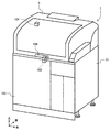
- 2 to 5 are perspective views showing the appearance of the automatic analyzer according to the present embodiment, FIG. 2 shows a state in which the safety cover is closed, and FIG. 3 shows a state in which the safety cover is in the fully open position.
- 4 is a diagram showing a state in which the safety cover and the opening / closing lid are in the fully open position
- FIG. 5 is a diagram showing a state in which the safety cover is moved from the state of FIG. 4 to the fully closed position.
- the downward direction in FIG. 1 as the front direction of the automatic analyzer the right direction in FIG. 1 as the right direction, and the front direction with respect to the paper surface in FIG. 1 as the upward direction
- the arrangement of the host computer in FIG. 1 is not specified.
- the automatic analyzer 1 includes a reagent cold storage 2, a safety cover 3, a sample transfer mechanism 4, a sample dispensing mechanism 5, a chip magazine 6, a chip transfer mechanism 7, an incubator 8, a sample dispensing chip buffer 9, and a chip.
- the host computer (operation unit) 23 controls the overall operation of the automatic analyzer 1.
- the automatic analyzer 1 has a side cover 21 (only the right side surface is shown) and a front cover so as to accommodate at least a part of the analyzer that analyzes the sample to be analyzed.
- a pretreatment area provided on the work surface 22 on the housing so as to include a housing composed of 103, a rear cover (not shown), a housing frame (not shown), and a part of the analyzer.
- the incubator cover 106 (first area cover) arranged so as to cover the (first area) and the incubator cover 106 (first area cover) for accessing the inside from the outside of the pretreatment area (first area).
- An opening / closing lid 105 rotatably provided between (see FIG. 3), a work surface 22 and an incubator cover 106 (first area cover) are arranged so as to cover the upper end of the work surface 22 (see FIG. 3).
- a safety cover 3 (second area cover) rotatably provided between the second fully open position and the second fully closed position with respect to the housing (at the rear end) is provided.
- the safety cover 3 is supported on one side of the upper surface of the housing by, for example, a hinge support shaft, and is configured to be openable and closable by being rotatably provided around the hinge support shaft. That is, the safety cover 3 is rotatably supported between the closed position (second fully closed position) and the open position (second fully open position) with the hinge support shaft as the center of rotation.
- the closing position of the safety cover 3 is defined by the lower end being supported by the table surface (working surface 22).
- the open position of the safety cover 3 is defined by the opening limit due to the configuration of the mechanical stopper (not shown).
- the safety cover 3 is provided with an interlock 101, and when it is detected by the open / close detection sensor function of the interlock 101 that the safety cover 3 is opened, the drive voltage of each drive unit in the automatic analyzer 1 is used. Is shut off, and the operation of each drive unit of the automatic analyzer 1 is stopped. As a result, it is possible to eliminate the risk of contact with the operation target of the operator while the device is in operation.
- a solenoid lock mechanism 102 that can put a barb between the housing and the safety cover 3 is provided at the end of the safety cover 3 in the closed position, for example, on the side opposite to the center of rotation, and automatic analysis is performed.
- the solenoid lock mechanism 102 is energized to lock the safety cover 3 to prevent the operator from opening the safety cover 3 and keep the safety cover 3 in a closed state.
- an erroneous operation such as the operator inadvertently opening the safety cover 3 in the analysis operation and stopping the device, which leads to a process related to restart and a delay in reporting to the patient.
- the energization of the solenoid lock mechanism 102 is stopped, the lock is released, and the safety cover 3 can be opened.
- the safety cover 3 is assisted in opening and closing by, for example, a gas damper, and can be opened to the reference height which is the open position with a small force. In the open position, the open position is maintained and the safety cover 3 is closed by its own weight. It is designed with a force balance that does not rotate. However, the safety cover 3 can be moved to the closed position with a small force.
- the operator grabs and lifts the handles 104 provided on all of the safety cover 3 to move the safety cover 3 to the open position, and lifts the arm and upper body from the gap between the work surface 22 and the front side of the safety cover 3.
- various operating mechanism groups provided on the work surface 22 can be cleaned or replaced, the work surface 22 can be cleaned, or the reagent container 24 can be replaced.
- the specified height at which the safety cover 3 maintains the open position is, for example, a height that even a relatively short person can reach and close in consideration of the average height and variation of a person who can be an operator. Moreover, it is desirable that the height is designed so that even a relatively tall person can secure a sufficient work space.
- the sample transport mechanism 4 is composed of, for example, a belt conveyor, a rack handler, or the like, and transports a sample rack 26 on which a sample container 25 containing a sample such as a sample is erected in the automatic analyzer 1 to transport the sample transfer mechanism 4. Move to the range of motion of 5.
- a plurality of unused sample dispensing chips 27 and a plurality of unused reaction vessels 28 are placed in the chip magazine 6.
- the chip magazine 6 is configured to be detachable from the automatic analyzer 1, and is arranged on the upper surface of the automatic analyzer 1 by the operator with the sample dispensing tip 27 and the reaction vessel 28 placed therein.
- the tip transfer mechanism 7 is configured to be movable in the plane direction and the Z-axis direction, and is movable above the tip magazine 6, a part of the incubator 8, the sample dispensing tip buffer 9, and the tip disposal hole 10. It is configured.
- the chip transfer mechanism 7 grips the reaction vessels 28 one by one from the chip magazine 6 and moves them to an empty slot of the incubator 8. Further, the tip transfer mechanism 7 grips the sample dispensing tips 27 one by one from the tip magazine 6 and moves them to the sample dispensing tip buffer 9.
- the sample dispensing tip buffer 9 is a buffer on which the sample dispensing tip 27 gripped and conveyed by the chip conveying mechanism 7 is temporarily placed.
- the sample dispensing tip 27 is configured to be detachable from the sample dispensing mechanism 5, and the sample dispensing mechanism 5 in a state where the sample dispensing tip 27 is not mounted moves to the sample dispensing tip buffer 9. As a result, the unused sample dispensing tip 27 can be attached.
- the incubator 8 has a disk shape and is configured to be rotatable in the circumferential direction.
- the incubator 8 can hold a plurality of reaction vessels 28 along the circumferential direction, and the rotation of the incubator 8 can move each reaction vessel 28 to a predetermined position on the rotation path.
- the incubator 8 has a temperature control function and a heat insulating function for controlling the temperature control.
- the sample dispensing mechanism 5 moves to the upper part of the sample dispensing tip buffer 9 without mounting the sample dispensing tip 27, mounts any one of the unused sample dispensing tips 27, and mounts the sample. It moves to the top of the container 25 and sucks the sample into the sample dispensing tip 27. After that, it moves to the upper part of the reaction vessel 28 mounted on the incubator 8 and discharges the internal form of the sample dispensing tip 27 into the reaction vessel 28. After that, the sample dispensing mechanism 5 moves to the upper part of the chip disposal hole 10, detaches the sample dispensing chip 27, and drops it into the chip disposal hole 10.
- the reagent cold storage 2 has a cylindrical shape in which the upper open end is sealed by a cover, and houses the reagent disk 29 inside. Further, the cover on the upper surface of the reagent cold storage 2 is provided with a reagent container loading port 30 for attaching and detaching the reagent container 24 to and from the reagent disk 29. Further, the reagent container loading port 30 is provided with an openable / closable reagent container loading port lid 31.
- the reagent cold storage 2 has a temperature control function and a heat insulating function in order to control the reagent container 24 to a constant temperature.
- the reagent disk 29 has slots for holding a plurality of reagent containers 24 radially along the circumferential direction.
- the reagent disk 29 is configured to be rotatable around a central axis extending in the vertical axis direction, and by rotating the reagent disk 29 in the circumferential direction, each reagent container 24 is moved to a predetermined position on a transport path. Can be moved. For example, by rotating the reagent disk 29, the reagent container 24 containing the target reagent can be moved to the reagent dispensing position 32.
- the reagent dispensing position 32 of the reagent disk 29 is provided with an opening through which the reagent of the reagent container 24 can be sucked by the reagent dispensing probe 11.
- the reagent dispensing probe 11 is configured in an arm shape that can rotate in the horizontal direction with respect to a rotation axis extending in the horizontal direction and extending one end in the vertical direction, and is horizontally formed by an actuator (not shown) or the like. It is configured to be rotatable in the direction and movable in the vertical direction.
- the reagent dispensing probe 11 is a reagent dispensing pipette provided at the lower part of the end (the other end) opposite to the rotation axis from the reagent container 24 conveyed to the reagent dispensing position 32 by the reagent disk 29.
- a predetermined amount of reagent is aspirated by (not shown) and dispensed into the reaction vessel 28 held in the incubator 8.
- the reagent stirring mechanism 12 is, for example, a magnetic particle stirring arm that extends horizontally and can rotate horizontally with respect to a rotation axis extending vertically at one end, and the other end is a reagent by a rotation operation. It is configured to be movable up to the upper part of the dispensing position 32.
- a paddle-shaped or spiral magnetic particle stirring mechanism for example, is provided at the lower portion of the end (the other end) of the magnetic particle stirring arm 12 opposite to the rotation axis of the reagent stirring mechanism 12.
- the reagent stirring mechanism 12 stirs the reagent by lowering the magnetic particle stirring mechanism in the reagent containing the magnetic particles, for example, and rotating the magnetic particle stirring mechanism.
- the reagent stirring mechanism 12 stirs the reagent immediately before dispensing the reagent by the reagent dispensing probe 11 in order to prevent precipitation of magnetic particles in the reagent. After stirring the reagent, the reagent stirring mechanism 12 moves the magnetic particle stirring mechanism to a cleaning mechanism (not shown) containing a cleaning liquid, and rotates the magnetic particle stirring mechanism for cleaning.
- the reaction vessel 28 of the incubator 8 is controlled to a predetermined temperature after the predetermined reagent and the sample are dispensed, and the reaction is promoted for a predetermined time.
- the reaction vessel transport mechanism 20 transports the reaction vessel 28 between the incubator 8, the reaction liquid washing / discharging suction position 15, the reaction liquid stirring mechanism 16, the reaction liquid suction position 17, and the reaction vessel disposal hole 19.
- reaction liquid suction discharge probe 14 when the reaction vessel 28 containing the reaction liquid of the reagent and the sample is transported from the incubator 8 to the reaction liquid washing discharge suction position 15 by the reaction vessel transport mechanism 20, the reaction of the reaction vessel 28 The unnecessary portion of the liquid is sucked, and the buffer liquid is discharged into the reaction vessel 28.
- reaction liquid stirring mechanism 16 stirs the reaction liquid in the reaction vessel 28.
- the reaction liquid in the reaction vessel 28 is conveyed by a suction mechanism (not shown). Is aspirated to detect the physical properties of the reaction solution. Examples of the physical characteristics of the reaction solution detected by the detection unit 18 include, but are not limited to, a light emission amount, a scattered light amount, a transmitted light amount, a current value, and a voltage value.
- the detection unit 18 may perform analysis while holding the reaction solution in the reaction vessel 28.
- the reaction vessel transport mechanism 20 moves the reaction vessel 28 containing the reaction liquid for which the analysis by the detection unit 18 has been completed to the upper part of the reaction vessel disposal hole 19 and discards it in the reaction vessel disposal hole 19.
- one reaction vessel 28 may be used for a plurality of measurements. In that case, the reaction vessel 28 is washed after discarding the reaction solution in the reaction vessel 28 for which the analysis has been completed.
- the incubator 8, the reaction liquid suction / discharge probe 14, the reaction liquid washing / discharge suction position 15, the reaction liquid stirring mechanism 16, and the reaction which are the configurations and positions for pretreating the sample before the detection by the detection unit 18.
- the liquid suction position 17, the reaction vessel transport mechanism 20, and the like are arranged together with the detection unit 18 in the pretreatment region (first region) covered with the incubator cover 106.
- the pretreatment area is an area that requires environmental control such as temperature adjustment and shading, and the incubator cover 106 and the opening / closing lid 105 (described later) are provided with heat insulating performance and shading performance in order to perform accurate temperature control and shading. ing.
- each mechanism related to the pretreatment is compactly arranged, and the pretreatment area is configured to be as small as possible. If the heat insulating space such as the pretreatment area becomes wide, the temperature distribution is likely to occur, so it is difficult to control the temperature in the space to be uniform, and the time until the set temperature is reached. Also, the warm-up time until it becomes measurable becomes long. Therefore, it is important to make the pretreatment area, which is a heat insulating space, as small as possible. Further, since the pretreatment area includes the detection unit 18, it is a light-shielding space, and the inner surface of the incubator cover 106 and the opening / closing lid 105 is black in order to suppress the reflection of stray light.
- Each configuration placed inside the pretreatment area (first area) needs to be maintained regularly or as needed.
- the operator pinches the opening / closing lid knob 107 provided at the front of the opening / closing lid 105 of the incubator cover 106 and moves the opening / closing lid 105 upward from the closed position (first fully closed position) to the release position (first fully open position). Maintenance is performed by moving to the position) and accessing the inside of the pretreatment area through the opening 108.
- the size of the opening 108 is provided so that the operator can access each mechanism in the pretreatment area with both hands and perform maintenance work.
- the safety cover 3 and the incubator cover 106 are operated with the opening / closing lid 105 (not shown in FIG. 2) closed.
- the safety cover 3 cannot be opened because the safety cover 3 is locked by the solenoid lock mechanism 102.
- the operator grasps and lifts the handle portion 104 of the safety cover 3 in the standby state or the system off state in which the device power is turned off, as shown in FIG. It is possible to make a transition to a state in which the safety cover 3 is open, that is, a state in which the safety cover 3 is in the open position.
- the reagent container loading port lid 31 As shown in FIG. 3, when the safety cover 3 is opened, the reagent container loading port lid 31, the opening / closing lid 105 of the incubator cover 106, the reagent dispensing probe 11, and the reagent dispensing probe 11, which are periodic cleaning points on the work surface 22, are The operator can access the reagent stirring mechanism 12. Of these, the reagent container loading palate 31 is accessed most frequently by the operator, and is opened and closed each time the reagent container 24 is replaced.
- the operator grasps the handle portion 104 of the safety cover 3 to move the safety cover 3 to the open position, and also pinches the opening / closing lid knob 107 of the opening / closing lid 105 of the incubator cover 106 to open / close the lid 105. Is moved to the open position, and the cleaning work of the configuration related to the pretreatment in the pretreatment area is performed. In the cleaning work, the operator inserts an arm into the work area through the opening 108 through the gap between the incubator cover 106 and the opening / closing lid 105 to perform the cleaning work, so that the opening / closing amount of the opening / closing lid 105 needs to be sufficiently large. be.
- the opening / closing lid 105 has an open holding function that holds an open position (first fully open position) against its own weight when one end on the side far from the center of rotation is moved to a position higher than a predetermined reference height. have. Further, the open / close holding function of the open / close lid 105 is such that when one end of the open / close lid 105 is pushed down below the reference height, the open / close lid 105 moves to the closed position (first fully closed position) by its own weight. Release the holding of 105.
- the opening / closing lid 105 of the safety cover 3 and the incubator cover 106 in the present embodiment is in the vertical direction at the opening position (first fully open position) of the end portion of the opening / closing lid 105 on the side far from the rotation center.
- the height of the safety cover 3 is configured to be higher than the height in the vertical direction of the inner surface at the closed position (second fully closed position) of the safety cover 3. Therefore, when the safety cover 3 is closed with the opening / closing lid 105 of the incubator cover 106 in the open position, the opening / closing lid 105 abuts on the abutting portion 301 on the inner surface of the safety cover 3 to reach the open position (first fully open position).
- the opening / closing cover 105 moves to the closing position (first fully closed position) by its own weight. That is, when the opening / closing lid 105 is in the open position (first fully open position) and the safety cover 3 is in the open position (second fully open position), the safety cover 3 is from the open position to the closed position (second fully closed position). With the movement to the position), the opening / closing cover 105 moves to the closing position (first fully closed position).
- FIG. 6 is a vertical sectional view of the incubator cover and the opening / closing lid.
- the incubator cover 106 and the opening / closing lid 105 are arranged over the entire inner surface (the surface on the pretreatment region side) of the external cover 113 which constitutes a part of the external appearance of the device. It is composed of a three-layer structure of a heat insulating member 114 and a light shielding member 115 arranged over the entire inner surface (surface on the pretreatment region side) of the heat insulating member.
- the exterior cover 113 corresponds to the appearance of the device, it is desirable to use, for example, a cover member having the same material and color as the cover member having other configurations on the work surface 22. Further, since the incubator cover 106 and the opening / closing lid 105 are contacted from the outside by an operator or the like, for example, a cover made of ABS (Acrylonitrile butadiene styrene) resin or the like, which is harder than the heat insulating member 114 or the light shielding member 115, is desirable.
- ABS Acrylonitrile butadiene styrene
- the contact portion 301 of the safety cover 3 with the opening / closing lid 105 a material having strong friction, a material having a small frictional force, a shape having a small frictional force, and the like are used while considering the material and the shape of the opening / closing lid 105. ..
- the contact portion 301 of the safety cover 3 with the opening / closing lid 105 has a flat structure with less catching.
- the contact portion 301 is made of a metal or a self-lubricating POM (Polyoxymethylene resin) material that wears little even when rubbed against the resin component used for the opening / closing lid 105.
- the heat insulating member 114 is, for example, a foaming material, and the foaming material may be formed by sticking the foaming material on the inner surface of the incubator cover 106 or the opening / closing lid 105, or may be formed by spraying.
- the inside of the pretreatment area covered by the incubator cover 106 and the opening / closing lid 105 by the heat insulating member 114 has a heat insulating function from the external environment.
- the light-shielding member 115 is, for example, a black sheet or a black paint, and it does not matter which one is used.
- the inside of the pretreatment area covered by the incubator cover 106 and the opening / closing lid 105 by the light-shielding member 115 has a light-shielding function from the external environment.
- a packing 117 made of sponge rubber is placed on the entire circumference of the opening 108. It is arranged over.
- the packing 117 is crushed at a constant rate by the weight of the opening / closing lid 105 to realize higher airtightness.
- the packing 117 is arranged and structured so as not to be worn by the friction generated when the opening / closing lid 105 is opened / closed. In the present embodiment, the packing 117 is worn and powder falls from above when the opening / closing lid 105 is opened / closed. It is attached to the incubator cover 106 side so that it does not exist. However, this is not limited to the case where the wear of the packing 117 can be appropriately suppressed and managed, and the packing 117 may be attached to the outer periphery of the opening / closing lid 105.
- a downward rib 118 is provided on the outer periphery of the opening / closing lid 105 so as to be located outside the packing 117 at the closed position.
- a so-called labyrinth effect can be expected by providing the rib 118 on the outer periphery of the opening / closing lid 105, and the heat insulating effect is improved by suppressing the inflow of outside air into the pretreatment area and the outflow of air from the pretreatment area, and the outside light is prevented. It can be expected that the light blocking effect will be improved by blocking.
- FIG. 7 and 8 are front views showing the incubator cover and the opening / closing lid taken out
- FIG. 7 is a view showing the case where the opening / closing lid is in the closed position
- FIG. 8 is a view showing the case where the opening / closing lid is in the open position. be.
- the opening angle ⁇ at the opening position of the opening / closing lid 105 in the present embodiment is configured to be ⁇ ⁇ 90 °. Therefore, when the safety cover 3 is closed with the opening / closing lid 105 of the incubator cover 106 in the open position and the opening / closing lid 105 comes into contact with the contact portion 301 on the inner surface of the safety cover 3, the safety cover 3 becomes the opening / closing lid 105. Since the direction of the applied force is the direction in which the opening / closing lid 105 closes (the direction of the closing position), it is possible to prevent a large load from being applied to the configuration of the rotation center portion of the opening / closing lid 105 (for example, the hinge portion 109). Can be done.
- the opening / closing lid 105 is pushed in the closing position direction by the safety cover 3 and pushed down from the reference height maintained at the open position (first fully open position), so that the opening / closing lid 105 is pushed down by its own weight to the closing position (first fully closed position). Move to position).
- the shape of the contact portion of the opening / closing lid 105 with the safety cover 3 is an oblique shape or an arc shape that tends to generate a force in the closing direction of the opening / closing lid 105, thereby relaxing the limitation of the opening angle. It may be a structure that does.
- FIG. 9 is a flowchart showing a maintenance processing procedure by the operator.
- the automatic analyzer 1 performs a reset operation when the operator selects a maintenance button (not shown) of the host computer 200 or the like on the operation screen or the like, and determines whether or not the device can transition to the maintenance state (step S100).
- step S100 determines whether the automatic analyzer 1 cannot transition to the maintenance state. If the determination result in step S100 is NO, that is, if the automatic analyzer 1 cannot transition to the maintenance state, the process returns to the maintenance button selection standby state. If the determination result in step S100 is NO, an alarm or the like is issued to urge the operator to work so that the state can be changed to the maintenance state.
- step S100 determines whether the maintenance state can be entered. If the determination result in step S100 is YES, that is, if it is determined that the maintenance state can be entered, the maintenance state is entered and the unit is moved to the evacuation position at the time of cleaning, which interferes with the work in maintenance. Move (step S110).
- step S110 When the movement of each mechanism in step S110 to the retracted position is completed, the operator manually moves the safety cover 3 to the open position (second fully open position) according to the guidance on the screen to open it (step S120), and the incubator cover 106 is opened.
- the opening / closing cover 105 is manually moved to the open position (first fully open position) to open (step S130), and the pretreatment area is cleaned (step S150).
- the operator for example, wears rubber gloves and uses a cotton swab, absorbent cotton, a cleaning agent, alcohol, or the like for cleaning.
- step S140 When the cleaning of step S140 is completed, the operator subsequently manually moves the opening / closing lid 105 of the incubator cover 106 to the closing position (first fully closed position) to close the incubator cover 106 (step S150), and then closes the incubator cover 106.
- the safety cover 3 is manually moved to the closed position (second fully closed position) to close it (step S160), and the end of maintenance is selected on the screen (step S170) to end the process.
- an erroneous operation such as manually closing the safety cover 3 with the opening / closing lid 105 of the incubator cover 106 in the open position occurs in the process of steps S140 to S160.
- an erroneous operation causes, for example, the operator to leave the automatic analyzer 1 when preparing or cleaning up the cleaning tool.
- another operator may close the safety cover 3 without noticing that the opening / closing lid 105 is open during cleaning.
- the opening / closing lid 105 of the incubator cover 106 is surely secured while preventing the occurrence of breakage by suppressing the load acting on the opening / closing lid 105 and the like. Since it can be closed to, it is possible to maintain the light-shielding / heat-insulating surface performance of the pretreatment area that requires environmental control such as temperature adjustment and light-shielding.
- FIG. 10 and 11 are front views showing the incubator cover and the opening / closing lid of the first and second comparative examples
- FIG. 10 shows the case where the opening / closing lid in the first comparative example is in the open position
- FIG. 11 shows the case where the opening / closing lid is in the open position.
- the case where the opening / closing lid in the second comparative example is in the open position is shown respectively.
- the opening / closing lid 105A becomes a stick state, and a load is applied in a direction that hinders the closing operation of the safety cover 3.
- the hinge portion 109 of the opening / closing lid 105A is damaged due to a large load.
- the opening angle ⁇ at the opening position of the opening / closing lid 105 of the incubator cover 106 is set to ⁇ ⁇ 90 °, the safety cover is covered with the opening / closing lid 105 in the open position.
- the direction of the force applied from the safety cover 3 to the opening / closing lid 105 is the direction in which the opening / closing lid 105 closes (the direction of the closing position). )
- the hinge portion 109 it is possible to prevent a large load from being applied to the configuration of the rotation center portion of the opening / closing lid 105 (for example, the hinge portion 109).
- the opening / closing lid of the pretreatment area when the opening / closing lid of the pretreatment area is removable, the opening / closing lid removed to open the opening at the start of maintenance work may be forgotten to be attached after the maintenance work is completed. Conceivable. If the pretreatment is performed without closing the opening of the pretreatment area, the pretreatment will be performed with the pretreatment area shielded from light and the temperature adjustment is insufficient, and the accuracy of the analysis result will be reduced. There is a risk that it will end up. As a method of preventing forgetting to attach the opening / closing lid, it is conceivable to use a sensor that detects the opening / closing state, but this causes complicated structure and cost increase. Further, since the opening of the pretreatment portion needs to be large enough to accommodate both hands of the operator, the removable opening / closing lid also becomes large, and it becomes necessary to secure a temporary storage space.
- the opening / closing lid 105 of the incubator cover 106 when the opening / closing lid 105 of the incubator cover 106 is in the open position (first fully open position) and the safety cover 3 is in the open position (second fully open position), it is safe. Since the opening / closing lid 105 is configured to move to the closed position (first fully closed position) as the cover 3 moves from the open position (second fully open position) to the closed position (second fully closed position).
- the opening / closing lid 105 provided in the opening for accessing the area covered with the cover which requires environmental control such as temperature control and shading, can be reliably closed. Therefore, the analysis process can be performed in a state where the inside of the pretreatment area is sufficiently shielded from light and the temperature is adjusted, and the deterioration of the accuracy of the analysis result can be suppressed.
- This embodiment adopts an opening / closing lid that rotates in the forward direction instead of the opening / closing lid that rotates in the upward direction in the first embodiment.
- FIGS. 12 and 13 are views showing the incubator cover and the opening / closing lid taken out
- FIG. 12 is a front view when the opening / closing lid is in the open position
- FIG. 13 is a top view when the opening / closing lid is in the open position. be.
- the same members as those in the first embodiment are designated by the same reference numerals, and the description thereof will be omitted.
- FIGS. 12 and 13 the state of the opening / closing lid at the closed position is shown by a broken line.
- the opening / closing lid 205 is supported so as to be swingable in the horizontal direction by a support shaft 37a configured to extend one of the left-right directions (for example, the left end) in the vertical direction.
- the opening / closing lid 205 is attached in the closing direction by a closing spring 58 stretched between the first spring hooking portion 56 provided on the incubator cover 106 and the second spring hooking portion 57 provided on the opening / closing lid 205. It is being pushed. Further, the opening / closing lid 205 has a hook-shaped receiving claw 59 that extends along the rotation opening direction and has a convex shape below the tip, and has an open position (first fully open). In the position), the receiving claw 59 is fixed by the lock claw 53, so that the open position is maintained against the urging force in the closing direction by the closing spring 58. When the receiving claw 59 is not fixed by the lock claw 53, the opening / closing lid 205 is moved to the closing position (first fully closed position) by the urging force of the closing spring 58.
- the lock claw 53 is pivotally supported at one end in a vertically swingable manner around a horizontally arranged lock support shaft 52, and is formed in a hook shape having an upward convex shape at the other end, and is a lock spring. It is urged from below by 55. Further, a release convex portion 54 is provided between the lock support shaft 52 and the tip of the lock claw 53 so as to extend upward, and the release convex portion 54 is pushed downward from above. The lock claw 53 can be moved downward with.
- the receiving claw 59 and the locking claw 53 are arranged at positions where they mesh with each other when the opening / closing lid 205 is in the open position, and when the opening / closing lid 205 is moved to the open position, the locking claw 53 and the receiving claw 59 mesh with each other. As a result, it is maintained in the open position against the closing force of the closing spring 58.
- a release protrusion 60 is provided on the inner surface of the safety cover 3 so as to extend downward, and when the safety cover 3 moves to the closed position (second fully closed position), the release protrusion 60 is released.
- the lock claw 53 is pushed down and disengaged from the receiving claw 59 by abutting against the convex portion 54, and the opening / closing lid 205 is closed by the closing force of the closing spring 58 (first fully closed position). Will be moved to.
- the release protrusion 60 abuts on the release convex portion 54, and the engagement between the lock claw 53 and the receiving claw 59 is released.
- the opening / closing lid 205 moves to the closing position (first fully closed position) by the urging force of the closing spring 58. That is, when the opening / closing lid 205 is in the open position (first fully open position) and the safety cover 3 is in the open position (second fully open position), the safety cover 3 is from the open position to the closed position (second fully closed position). With the movement to the position), the opening / closing cover 205 moves to the closing position (first fully closed position).
- the present invention is not limited to the above embodiment, and includes various modifications and combinations within a range not deviating from the gist thereof. Further, the present invention is not limited to the one including all the configurations described in the above-described embodiment, and includes the one in which a part of the configurations is deleted.
- Host computer (operation unit), 24 ... Reagent container , 25 ... sample container, 26 ... sample rack, 27 ... sample dispensing chip, 28 ... reaction vessel, 29 ... reagent disk, 30 ... reagent container loading port, 31 ... reagent container loading hinge, 32 ... reagent dispensing position, 37a ... Support shaft, 52 ... Lock support shaft, 53 ... Lock claw, 54 ... Release convex part, 56, 57 ... Spring hook part, 59 ... Receiving claw, 60 ... Release protrusion, 101 ... Interlock, 102 ... Solson lock mechanism, 103 ... Front cover, 104 ... Handle, 105, 205 ... Opening and closing lid, 105A, 105B ...
- Opening and closing lid 106 ... Incubator cover, 108 ... Opening, 109 ... Hinge, 113 ... Exterior cover, 114 ... Insulation member, 115 ... light-shielding member, 117 ... packing, 118 ... rib, 200 ... host computer, 301 ... contact part
Landscapes
- Chemical & Material Sciences (AREA)
- Physics & Mathematics (AREA)
- Health & Medical Sciences (AREA)
- Life Sciences & Earth Sciences (AREA)
- Analytical Chemistry (AREA)
- Biochemistry (AREA)
- General Health & Medical Sciences (AREA)
- General Physics & Mathematics (AREA)
- Immunology (AREA)
- Pathology (AREA)
- Chemical Kinetics & Catalysis (AREA)
- Automatic Analysis And Handling Materials Therefor (AREA)
Priority Applications (4)
| Application Number | Priority Date | Filing Date | Title |
|---|---|---|---|
| US18/010,005 US20230324428A1 (en) | 2020-07-09 | 2021-02-05 | Automatic analyzer |
| EP21836832.2A EP4180819B1 (en) | 2020-07-09 | 2021-02-05 | Automated analyzer |
| JP2022534895A JP7405984B2 (ja) | 2020-07-09 | 2021-02-05 | 自動分析装置 |
| CN202180043668.2A CN115997132A (zh) | 2020-07-09 | 2021-02-05 | 自动分析装置 |
Applications Claiming Priority (2)
| Application Number | Priority Date | Filing Date | Title |
|---|---|---|---|
| JP2020118342 | 2020-07-09 | ||
| JP2020-118342 | 2020-07-09 |
Publications (1)
| Publication Number | Publication Date |
|---|---|
| WO2022009455A1 true WO2022009455A1 (ja) | 2022-01-13 |
Family
ID=79553246
Family Applications (1)
| Application Number | Title | Priority Date | Filing Date |
|---|---|---|---|
| PCT/JP2021/004442 Ceased WO2022009455A1 (ja) | 2020-07-09 | 2021-02-05 | 自動分析装置 |
Country Status (5)
| Country | Link |
|---|---|
| US (1) | US20230324428A1 (https=) |
| EP (1) | EP4180819B1 (https=) |
| JP (1) | JP7405984B2 (https=) |
| CN (1) | CN115997132A (https=) |
| WO (1) | WO2022009455A1 (https=) |
Families Citing this family (1)
| Publication number | Priority date | Publication date | Assignee | Title |
|---|---|---|---|---|
| EP4283372B1 (en) * | 2019-08-06 | 2025-10-01 | Leica Biosystems Imaging, Inc. | Digital pathology apparatus housing with rail system, speakerless audio system, and electromagnetic radiation shielding |
Citations (6)
| Publication number | Priority date | Publication date | Assignee | Title |
|---|---|---|---|---|
| JPS5651667A (en) * | 1979-10-03 | 1981-05-09 | Hitachi Ltd | Liquid sample analyzer |
| JP3141576U (ja) * | 2008-02-27 | 2008-05-08 | 株式会社日立ハイテクノロジーズ | 自動分析装置 |
| JP2010243191A (ja) * | 2009-04-01 | 2010-10-28 | Toshiba Corp | 自動分析装置 |
| JP2013072799A (ja) | 2011-09-28 | 2013-04-22 | Hitachi High-Technologies Corp | 自動分析装置 |
| JP2013076678A (ja) * | 2011-09-30 | 2013-04-25 | Sysmex Corp | 検体処理装置 |
| WO2018230198A1 (ja) * | 2017-06-16 | 2018-12-20 | 株式会社 日立ハイテクノロジーズ | 自動分析装置 |
Family Cites Families (9)
| Publication number | Priority date | Publication date | Assignee | Title |
|---|---|---|---|---|
| DE59410066D1 (de) * | 1993-04-23 | 2002-04-11 | Boehringer Mannheim Gmbh | System zur Analyse von Inhaltsstoffen flüssiger Proben |
| JP3616464B2 (ja) * | 1996-08-03 | 2005-02-02 | 株式会社堀場製作所 | 元素分析装置 |
| JP3764326B2 (ja) * | 2000-08-28 | 2006-04-05 | 株式会社日立製作所 | 自動分析装置 |
| JP3964291B2 (ja) * | 2002-09-06 | 2007-08-22 | 富士フイルム株式会社 | 分析機器 |
| SG11201500649UA (en) * | 2012-08-03 | 2015-03-30 | Sony Corp | Nucleic acid analysis apparatus, microchip for nucleic acid analysis, and method for mounting microchip in nucleic acid analysis apparatus |
| EP3043184A4 (en) * | 2013-09-02 | 2017-04-05 | Hitachi High-Technologies Corporation | Automated analyzer |
| JP6783514B2 (ja) * | 2015-11-13 | 2020-11-11 | 古野電気株式会社 | 分析装置 |
| JP2017202072A (ja) * | 2016-05-11 | 2017-11-16 | 日立アプライアンス株式会社 | 電気洗濯機 |
| KR102152629B1 (ko) * | 2018-12-10 | 2020-09-07 | 주식회사 이앤에스헬스케어 | 광진단부 교체 모듈을 구비한 체외진단장치 |
-
2021
- 2021-02-05 US US18/010,005 patent/US20230324428A1/en active Pending
- 2021-02-05 JP JP2022534895A patent/JP7405984B2/ja active Active
- 2021-02-05 CN CN202180043668.2A patent/CN115997132A/zh active Pending
- 2021-02-05 EP EP21836832.2A patent/EP4180819B1/en active Active
- 2021-02-05 WO PCT/JP2021/004442 patent/WO2022009455A1/ja not_active Ceased
Patent Citations (6)
| Publication number | Priority date | Publication date | Assignee | Title |
|---|---|---|---|---|
| JPS5651667A (en) * | 1979-10-03 | 1981-05-09 | Hitachi Ltd | Liquid sample analyzer |
| JP3141576U (ja) * | 2008-02-27 | 2008-05-08 | 株式会社日立ハイテクノロジーズ | 自動分析装置 |
| JP2010243191A (ja) * | 2009-04-01 | 2010-10-28 | Toshiba Corp | 自動分析装置 |
| JP2013072799A (ja) | 2011-09-28 | 2013-04-22 | Hitachi High-Technologies Corp | 自動分析装置 |
| JP2013076678A (ja) * | 2011-09-30 | 2013-04-25 | Sysmex Corp | 検体処理装置 |
| WO2018230198A1 (ja) * | 2017-06-16 | 2018-12-20 | 株式会社 日立ハイテクノロジーズ | 自動分析装置 |
Non-Patent Citations (1)
| Title |
|---|
| See also references of EP4180819A4 |
Also Published As
| Publication number | Publication date |
|---|---|
| EP4180819B1 (en) | 2025-05-28 |
| CN115997132A (zh) | 2023-04-21 |
| EP4180819A4 (en) | 2024-07-03 |
| JP7405984B2 (ja) | 2023-12-26 |
| US20230324428A1 (en) | 2023-10-12 |
| JPWO2022009455A1 (https=) | 2022-01-13 |
| EP4180819A1 (en) | 2023-05-17 |
Similar Documents
| Publication | Publication Date | Title |
|---|---|---|
| JP3764326B2 (ja) | 自動分析装置 | |
| US9194878B2 (en) | Automatic analysis device | |
| EP2703819A1 (en) | Sample processing apparatus and sample processing method | |
| CN110140054A (zh) | 自动分析装置 | |
| US20080085215A1 (en) | Analyzer | |
| JP2008216173A (ja) | 自動分析装置 | |
| JP2012021862A (ja) | 自動分析装置 | |
| US20090081081A1 (en) | Pipette tip supplier and sample analyzer | |
| JP6886837B2 (ja) | 自動分析装置 | |
| JP7032235B2 (ja) | 自動分析装置 | |
| JP7405984B2 (ja) | 自動分析装置 | |
| JP5258615B2 (ja) | 自動分析装置 | |
| JP7499918B2 (ja) | 自動分析装置 | |
| US9052301B2 (en) | Automatic analyzer | |
| CN115917326B (zh) | 开闭盖装置以及具备该开闭盖装置的自动分析装置 | |
| JP6091964B2 (ja) | 自動分析装置 | |
| JP5216820B2 (ja) | 分注装置および核酸分析装置 | |
| CN115769079A (zh) | 自动分析装置 | |
| JPWO2020075818A1 (ja) | キュベット廃棄ユニット | |
| US20250224416A1 (en) | Automatic analyzer | |
| JPWO2022009455A5 (https=) | ||
| EP4379390A1 (en) | Automatic analysis device, and guidance method used in automatic analysis device | |
| CN114545002A (zh) | 一种样本分析装置和方法 |
Legal Events
| Date | Code | Title | Description |
|---|---|---|---|
| 121 | Ep: the epo has been informed by wipo that ep was designated in this application |
Ref document number: 21836832 Country of ref document: EP Kind code of ref document: A1 |
|
| ENP | Entry into the national phase |
Ref document number: 2022534895 Country of ref document: JP Kind code of ref document: A |
|
| ENP | Entry into the national phase |
Ref document number: 2021836832 Country of ref document: EP Effective date: 20230209 |
|
| NENP | Non-entry into the national phase |
Ref country code: DE |
|
| WWG | Wipo information: grant in national office |
Ref document number: 2021836832 Country of ref document: EP |