WO2022009455A1 - Automated analyzer - Google Patents
Automated analyzer Download PDFInfo
- Publication number
- WO2022009455A1 WO2022009455A1 PCT/JP2021/004442 JP2021004442W WO2022009455A1 WO 2022009455 A1 WO2022009455 A1 WO 2022009455A1 JP 2021004442 W JP2021004442 W JP 2021004442W WO 2022009455 A1 WO2022009455 A1 WO 2022009455A1
- Authority
- WO
- WIPO (PCT)
- Prior art keywords
- opening
- cover
- closing lid
- open position
- closed position
- Prior art date
Links
- 238000007781 pre-processing Methods 0.000 abstract 3
- 239000003153 chemical reaction reagent Substances 0.000 description 73
- 239000000523 sample Substances 0.000 description 60
- 238000006243 chemical reaction Methods 0.000 description 52
- 230000007246 mechanism Effects 0.000 description 50
- 239000012295 chemical reaction liquid Substances 0.000 description 26
- 238000003756 stirring Methods 0.000 description 26
- 238000012423 maintenance Methods 0.000 description 22
- 238000004140 cleaning Methods 0.000 description 20
- 210000000078 claw Anatomy 0.000 description 18
- 238000004458 analytical method Methods 0.000 description 11
- 238000001514 detection method Methods 0.000 description 11
- 239000000463 material Substances 0.000 description 11
- 239000006249 magnetic particle Substances 0.000 description 9
- 238000012856 packing Methods 0.000 description 9
- 238000012546 transfer Methods 0.000 description 9
- 230000000052 comparative effect Effects 0.000 description 8
- 238000000034 method Methods 0.000 description 8
- 230000007723 transport mechanism Effects 0.000 description 8
- 230000008569 process Effects 0.000 description 5
- 230000000694 effects Effects 0.000 description 4
- 239000007788 liquid Substances 0.000 description 4
- 230000032258 transport Effects 0.000 description 4
- 238000005406 washing Methods 0.000 description 4
- 230000007613 environmental effect Effects 0.000 description 3
- 238000005187 foaming Methods 0.000 description 3
- 238000005259 measurement Methods 0.000 description 3
- 239000011347 resin Substances 0.000 description 3
- 229920005989 resin Polymers 0.000 description 3
- 230000007704 transition Effects 0.000 description 3
- 229920000742 Cotton Polymers 0.000 description 2
- XECAHXYUAAWDEL-UHFFFAOYSA-N acrylonitrile butadiene styrene Chemical compound C=CC=C.C=CC#N.C=CC1=CC=CC=C1 XECAHXYUAAWDEL-UHFFFAOYSA-N 0.000 description 2
- 229920000122 acrylonitrile butadiene styrene Polymers 0.000 description 2
- 239000004676 acrylonitrile butadiene styrene Substances 0.000 description 2
- 230000000903 blocking effect Effects 0.000 description 2
- 238000010586 diagram Methods 0.000 description 2
- 238000007599 discharging Methods 0.000 description 2
- 229920006324 polyoxymethylene Polymers 0.000 description 2
- 239000000843 powder Substances 0.000 description 2
- 238000012545 processing Methods 0.000 description 2
- LFQSCWFLJHTTHZ-UHFFFAOYSA-N Ethanol Chemical compound CCO LFQSCWFLJHTTHZ-UHFFFAOYSA-N 0.000 description 1
- 229930040373 Paraformaldehyde Natural products 0.000 description 1
- -1 Polyoxymethylene Polymers 0.000 description 1
- 230000009471 action Effects 0.000 description 1
- 239000012472 biological sample Substances 0.000 description 1
- 239000008280 blood Substances 0.000 description 1
- 210000004369 blood Anatomy 0.000 description 1
- 239000012459 cleaning agent Substances 0.000 description 1
- 230000006866 deterioration Effects 0.000 description 1
- 239000012530 fluid Substances 0.000 description 1
- 238000009413 insulation Methods 0.000 description 1
- 239000002184 metal Substances 0.000 description 1
- 238000012986 modification Methods 0.000 description 1
- 230000004048 modification Effects 0.000 description 1
- 239000003973 paint Substances 0.000 description 1
- 210000003254 palate Anatomy 0.000 description 1
- 239000013610 patient sample Substances 0.000 description 1
- 230000000737 periodic effect Effects 0.000 description 1
- 230000000704 physical effect Effects 0.000 description 1
- 238000001556 precipitation Methods 0.000 description 1
- 230000001681 protective effect Effects 0.000 description 1
- 238000004451 qualitative analysis Methods 0.000 description 1
- 238000004445 quantitative analysis Methods 0.000 description 1
- 230000002040 relaxant effect Effects 0.000 description 1
- 238000005507 spraying Methods 0.000 description 1
- 210000002700 urine Anatomy 0.000 description 1
- 239000002699 waste material Substances 0.000 description 1
Images


Classifications
-
- G—PHYSICS
- G01—MEASURING; TESTING
- G01N—INVESTIGATING OR ANALYSING MATERIALS BY DETERMINING THEIR CHEMICAL OR PHYSICAL PROPERTIES
- G01N35/00—Automatic analysis not limited to methods or materials provided for in any single one of groups G01N1/00 - G01N33/00; Handling materials therefor
- G01N35/10—Devices for transferring samples or any liquids to, in, or from, the analysis apparatus, e.g. suction devices, injection devices
- G01N35/1002—Reagent dispensers
-
- G—PHYSICS
- G01—MEASURING; TESTING
- G01N—INVESTIGATING OR ANALYSING MATERIALS BY DETERMINING THEIR CHEMICAL OR PHYSICAL PROPERTIES
- G01N35/00—Automatic analysis not limited to methods or materials provided for in any single one of groups G01N1/00 - G01N33/00; Handling materials therefor
-
- G—PHYSICS
- G01—MEASURING; TESTING
- G01N—INVESTIGATING OR ANALYSING MATERIALS BY DETERMINING THEIR CHEMICAL OR PHYSICAL PROPERTIES
- G01N35/00—Automatic analysis not limited to methods or materials provided for in any single one of groups G01N1/00 - G01N33/00; Handling materials therefor
- G01N35/02—Automatic analysis not limited to methods or materials provided for in any single one of groups G01N1/00 - G01N33/00; Handling materials therefor using a plurality of sample containers moved by a conveyor system past one or more treatment or analysis stations
- G01N35/025—Automatic analysis not limited to methods or materials provided for in any single one of groups G01N1/00 - G01N33/00; Handling materials therefor using a plurality of sample containers moved by a conveyor system past one or more treatment or analysis stations having a carousel or turntable for reaction cells or cuvettes
-
- B—PERFORMING OPERATIONS; TRANSPORTING
- B01—PHYSICAL OR CHEMICAL PROCESSES OR APPARATUS IN GENERAL
- B01L—CHEMICAL OR PHYSICAL LABORATORY APPARATUS FOR GENERAL USE
- B01L7/00—Heating or cooling apparatus; Heat insulating devices
-
- G—PHYSICS
- G01—MEASURING; TESTING
- G01N—INVESTIGATING OR ANALYSING MATERIALS BY DETERMINING THEIR CHEMICAL OR PHYSICAL PROPERTIES
- G01N35/00—Automatic analysis not limited to methods or materials provided for in any single one of groups G01N1/00 - G01N33/00; Handling materials therefor
- G01N2035/00178—Special arrangements of analysers
- G01N2035/00277—Special precautions to avoid contamination (e.g. enclosures, glove- boxes, sealed sample carriers, disposal of contaminated material)
-
- G—PHYSICS
- G01—MEASURING; TESTING
- G01N—INVESTIGATING OR ANALYSING MATERIALS BY DETERMINING THEIR CHEMICAL OR PHYSICAL PROPERTIES
- G01N35/00—Automatic analysis not limited to methods or materials provided for in any single one of groups G01N1/00 - G01N33/00; Handling materials therefor
- G01N2035/00178—Special arrangements of analysers
- G01N2035/00306—Housings, cabinets, control panels (details)
- G01N2035/00316—Detecting door closure
-
- G—PHYSICS
- G01—MEASURING; TESTING
- G01N—INVESTIGATING OR ANALYSING MATERIALS BY DETERMINING THEIR CHEMICAL OR PHYSICAL PROPERTIES
- G01N35/00—Automatic analysis not limited to methods or materials provided for in any single one of groups G01N1/00 - G01N33/00; Handling materials therefor
- G01N2035/00346—Heating or cooling arrangements
- G01N2035/00356—Holding samples at elevated temperature (incubation)
-
- G—PHYSICS
- G01—MEASURING; TESTING
- G01N—INVESTIGATING OR ANALYSING MATERIALS BY DETERMINING THEIR CHEMICAL OR PHYSICAL PROPERTIES
- G01N35/00—Automatic analysis not limited to methods or materials provided for in any single one of groups G01N1/00 - G01N33/00; Handling materials therefor
- G01N35/02—Automatic analysis not limited to methods or materials provided for in any single one of groups G01N1/00 - G01N33/00; Handling materials therefor using a plurality of sample containers moved by a conveyor system past one or more treatment or analysis stations
- G01N35/04—Details of the conveyor system
- G01N2035/0401—Sample carriers, cuvettes or reaction vessels
- G01N2035/0403—Sample carriers with closing or sealing means
- G01N2035/0405—Sample carriers with closing or sealing means manipulating closing or opening means, e.g. stoppers, screw caps, lids or covers
-
- G—PHYSICS
- G01—MEASURING; TESTING
- G01N—INVESTIGATING OR ANALYSING MATERIALS BY DETERMINING THEIR CHEMICAL OR PHYSICAL PROPERTIES
- G01N35/00—Automatic analysis not limited to methods or materials provided for in any single one of groups G01N1/00 - G01N33/00; Handling materials therefor
- G01N35/02—Automatic analysis not limited to methods or materials provided for in any single one of groups G01N1/00 - G01N33/00; Handling materials therefor using a plurality of sample containers moved by a conveyor system past one or more treatment or analysis stations
- G01N35/04—Details of the conveyor system
- G01N2035/0439—Rotary sample carriers, i.e. carousels
- G01N2035/0443—Rotary sample carriers, i.e. carousels for reagents
Definitions
- the present invention relates to an automatic analyzer.
- An automatic analyzer is a device that performs qualitative analysis or quantitative analysis of specific components contained in biological samples such as blood, urine, and spinal fluid. For example, many patient samples such as hospitals and medical examination facilities are shortened. It is an indispensable device for facilities that need to be processed in time.
- the pretreatment such as dispensing and stirring of the reaction solution and the reagent is shaded and the environment controlled pretreatment such as temperature adjustment is performed. It is done within the area.
- a sample disk for holding a plurality of samples, a reagent disk for holding a plurality of types of reagents, and a reaction disk for holding a plurality of reaction cells, which are arranged on the upper surface of the main body housing, are described.
- a plurality of dispensing mechanisms having a moving arm and a nozzle fixed to the arm to dispense the sample and the reagent to the reaction cell held in the reaction disk, and a plurality of dispensing mechanisms installed inside the main body housing.
- a scattered light measuring unit including a light source that irradiates the reaction cell with light and a light receiver that receives the scattered light generated from the reaction liquid in the reaction cell by the light irradiation, and arranged so as to cover the upper surface of the main body housing. It is provided with a protective cover provided with a light-shielding portion that shields external light and a transparent portion that can see through the inside, and the light-shielding portion covers at least an area of the reaction disk that is above the scattered light measuring portion. The device is disclosed.
- maintenance work such as cleaning and parts replacement in the environment-controlled pretreatment area covered with a cover is performed regularly or depending on the usage conditions. You are required to do it.
- the opening / closing lid provided in the opening above or in front of the cover covering the pretreatment area is opened, and the maintenance staff accesses the inside of the pretreatment area through the opening through the gap between the opening / closing lid and the cover. It is done by doing. Further, when the maintenance work is completed and the opening / closing lid is closed, the inside of the pretreatment area is kept in a state where the inside of the pretreatment area is shielded from light and the temperature is adjusted by the cover and the opening / closing lid.
- the opening / closing lid of the pretreatment area is removable, the opening / closing lid removed to open the opening at the start of maintenance work may be forgotten to be attached after the maintenance work is completed. Conceivable. If the pretreatment is performed without closing the opening of the pretreatment area, the pretreatment will be performed with the pretreatment area shielded from light and the temperature adjustment is insufficient, and the accuracy of the analysis result will be reduced. There is a risk that it will end up.
- the present invention has been made in view of the above, and an object of the present invention is to provide an automatic analyzer capable of reliably closing an opening / closing lid provided in an opening for accessing an area covered with a cover.
- the present application includes a plurality of means for solving the above problems.
- a housing for accommodating at least a part of an analyzer for analyzing a sample to be analyzed and a part of the analyzer are included.
- a first area cover arranged so as to cover the first area provided on the work surface on the housing so as to include the first area cover, and the first area cover provided for accessing the inside from the outside of the first area.
- the opening and closing is arranged so as to cover the opened opening so as to be openable and closable, and is rotatably provided between the first fully open position and the first fully closed position with respect to the first region cover at the end of the opening.
- the opening / closing lid is arranged so as to cover the upper part of the work surface and the first area cover, and is located between the second fully open position and the second fully closed position with respect to the housing at the end of the work surface.
- the second region cover is provided with a rotatably provided second region cover.
- the automatic analyzer is characterized in that the opening / closing lid moves to the first fully closed position with the movement from the second fully open position to the second fully closed position.
- the opening / closing lid provided in the opening for accessing the area covered with the cover can be reliably closed.
- FIG. 1 It is a front view which shows the incubator cover and the opening / closing lid of the 2nd comparative example, and is the figure which shows the case where the opening / closing lid is in an open position. It is a figure which shows by pulling out the incubator cover and the opening / closing lid which concerns on 2nd Embodiment, and is the front view when the opening / closing lid is in an open position. It is a figure which shows by pulling out the incubator cover and the opening / closing lid which concerns on 2nd Embodiment, and is the top view when the opening / closing lid is in an open position.
- FIG. 1 is a plan view schematically showing the configuration of the working surface of the automatic analyzer according to the present embodiment.
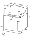
- 2 to 5 are perspective views showing the appearance of the automatic analyzer according to the present embodiment, FIG. 2 shows a state in which the safety cover is closed, and FIG. 3 shows a state in which the safety cover is in the fully open position.
- 4 is a diagram showing a state in which the safety cover and the opening / closing lid are in the fully open position
- FIG. 5 is a diagram showing a state in which the safety cover is moved from the state of FIG. 4 to the fully closed position.
- the downward direction in FIG. 1 as the front direction of the automatic analyzer the right direction in FIG. 1 as the right direction, and the front direction with respect to the paper surface in FIG. 1 as the upward direction
- the arrangement of the host computer in FIG. 1 is not specified.
- the automatic analyzer 1 includes a reagent cold storage 2, a safety cover 3, a sample transfer mechanism 4, a sample dispensing mechanism 5, a chip magazine 6, a chip transfer mechanism 7, an incubator 8, a sample dispensing chip buffer 9, and a chip.
- the host computer (operation unit) 23 controls the overall operation of the automatic analyzer 1.
- the automatic analyzer 1 has a side cover 21 (only the right side surface is shown) and a front cover so as to accommodate at least a part of the analyzer that analyzes the sample to be analyzed.
- a pretreatment area provided on the work surface 22 on the housing so as to include a housing composed of 103, a rear cover (not shown), a housing frame (not shown), and a part of the analyzer.
- the incubator cover 106 (first area cover) arranged so as to cover the (first area) and the incubator cover 106 (first area cover) for accessing the inside from the outside of the pretreatment area (first area).
- An opening / closing lid 105 rotatably provided between (see FIG. 3), a work surface 22 and an incubator cover 106 (first area cover) are arranged so as to cover the upper end of the work surface 22 (see FIG. 3).
- a safety cover 3 (second area cover) rotatably provided between the second fully open position and the second fully closed position with respect to the housing (at the rear end) is provided.
- the safety cover 3 is supported on one side of the upper surface of the housing by, for example, a hinge support shaft, and is configured to be openable and closable by being rotatably provided around the hinge support shaft. That is, the safety cover 3 is rotatably supported between the closed position (second fully closed position) and the open position (second fully open position) with the hinge support shaft as the center of rotation.
- the closing position of the safety cover 3 is defined by the lower end being supported by the table surface (working surface 22).
- the open position of the safety cover 3 is defined by the opening limit due to the configuration of the mechanical stopper (not shown).
- the safety cover 3 is provided with an interlock 101, and when it is detected by the open / close detection sensor function of the interlock 101 that the safety cover 3 is opened, the drive voltage of each drive unit in the automatic analyzer 1 is used. Is shut off, and the operation of each drive unit of the automatic analyzer 1 is stopped. As a result, it is possible to eliminate the risk of contact with the operation target of the operator while the device is in operation.
- a solenoid lock mechanism 102 that can put a barb between the housing and the safety cover 3 is provided at the end of the safety cover 3 in the closed position, for example, on the side opposite to the center of rotation, and automatic analysis is performed.
- the solenoid lock mechanism 102 is energized to lock the safety cover 3 to prevent the operator from opening the safety cover 3 and keep the safety cover 3 in a closed state.
- an erroneous operation such as the operator inadvertently opening the safety cover 3 in the analysis operation and stopping the device, which leads to a process related to restart and a delay in reporting to the patient.
- the energization of the solenoid lock mechanism 102 is stopped, the lock is released, and the safety cover 3 can be opened.
- the safety cover 3 is assisted in opening and closing by, for example, a gas damper, and can be opened to the reference height which is the open position with a small force. In the open position, the open position is maintained and the safety cover 3 is closed by its own weight. It is designed with a force balance that does not rotate. However, the safety cover 3 can be moved to the closed position with a small force.
- the operator grabs and lifts the handles 104 provided on all of the safety cover 3 to move the safety cover 3 to the open position, and lifts the arm and upper body from the gap between the work surface 22 and the front side of the safety cover 3.
- various operating mechanism groups provided on the work surface 22 can be cleaned or replaced, the work surface 22 can be cleaned, or the reagent container 24 can be replaced.
- the specified height at which the safety cover 3 maintains the open position is, for example, a height that even a relatively short person can reach and close in consideration of the average height and variation of a person who can be an operator. Moreover, it is desirable that the height is designed so that even a relatively tall person can secure a sufficient work space.
- the sample transport mechanism 4 is composed of, for example, a belt conveyor, a rack handler, or the like, and transports a sample rack 26 on which a sample container 25 containing a sample such as a sample is erected in the automatic analyzer 1 to transport the sample transfer mechanism 4. Move to the range of motion of 5.
- a plurality of unused sample dispensing chips 27 and a plurality of unused reaction vessels 28 are placed in the chip magazine 6.
- the chip magazine 6 is configured to be detachable from the automatic analyzer 1, and is arranged on the upper surface of the automatic analyzer 1 by the operator with the sample dispensing tip 27 and the reaction vessel 28 placed therein.
- the tip transfer mechanism 7 is configured to be movable in the plane direction and the Z-axis direction, and is movable above the tip magazine 6, a part of the incubator 8, the sample dispensing tip buffer 9, and the tip disposal hole 10. It is configured.
- the chip transfer mechanism 7 grips the reaction vessels 28 one by one from the chip magazine 6 and moves them to an empty slot of the incubator 8. Further, the tip transfer mechanism 7 grips the sample dispensing tips 27 one by one from the tip magazine 6 and moves them to the sample dispensing tip buffer 9.
- the sample dispensing tip buffer 9 is a buffer on which the sample dispensing tip 27 gripped and conveyed by the chip conveying mechanism 7 is temporarily placed.
- the sample dispensing tip 27 is configured to be detachable from the sample dispensing mechanism 5, and the sample dispensing mechanism 5 in a state where the sample dispensing tip 27 is not mounted moves to the sample dispensing tip buffer 9. As a result, the unused sample dispensing tip 27 can be attached.
- the incubator 8 has a disk shape and is configured to be rotatable in the circumferential direction.
- the incubator 8 can hold a plurality of reaction vessels 28 along the circumferential direction, and the rotation of the incubator 8 can move each reaction vessel 28 to a predetermined position on the rotation path.
- the incubator 8 has a temperature control function and a heat insulating function for controlling the temperature control.
- the sample dispensing mechanism 5 moves to the upper part of the sample dispensing tip buffer 9 without mounting the sample dispensing tip 27, mounts any one of the unused sample dispensing tips 27, and mounts the sample. It moves to the top of the container 25 and sucks the sample into the sample dispensing tip 27. After that, it moves to the upper part of the reaction vessel 28 mounted on the incubator 8 and discharges the internal form of the sample dispensing tip 27 into the reaction vessel 28. After that, the sample dispensing mechanism 5 moves to the upper part of the chip disposal hole 10, detaches the sample dispensing chip 27, and drops it into the chip disposal hole 10.
- the reagent cold storage 2 has a cylindrical shape in which the upper open end is sealed by a cover, and houses the reagent disk 29 inside. Further, the cover on the upper surface of the reagent cold storage 2 is provided with a reagent container loading port 30 for attaching and detaching the reagent container 24 to and from the reagent disk 29. Further, the reagent container loading port 30 is provided with an openable / closable reagent container loading port lid 31.
- the reagent cold storage 2 has a temperature control function and a heat insulating function in order to control the reagent container 24 to a constant temperature.
- the reagent disk 29 has slots for holding a plurality of reagent containers 24 radially along the circumferential direction.
- the reagent disk 29 is configured to be rotatable around a central axis extending in the vertical axis direction, and by rotating the reagent disk 29 in the circumferential direction, each reagent container 24 is moved to a predetermined position on a transport path. Can be moved. For example, by rotating the reagent disk 29, the reagent container 24 containing the target reagent can be moved to the reagent dispensing position 32.
- the reagent dispensing position 32 of the reagent disk 29 is provided with an opening through which the reagent of the reagent container 24 can be sucked by the reagent dispensing probe 11.
- the reagent dispensing probe 11 is configured in an arm shape that can rotate in the horizontal direction with respect to a rotation axis extending in the horizontal direction and extending one end in the vertical direction, and is horizontally formed by an actuator (not shown) or the like. It is configured to be rotatable in the direction and movable in the vertical direction.
- the reagent dispensing probe 11 is a reagent dispensing pipette provided at the lower part of the end (the other end) opposite to the rotation axis from the reagent container 24 conveyed to the reagent dispensing position 32 by the reagent disk 29.
- a predetermined amount of reagent is aspirated by (not shown) and dispensed into the reaction vessel 28 held in the incubator 8.
- the reagent stirring mechanism 12 is, for example, a magnetic particle stirring arm that extends horizontally and can rotate horizontally with respect to a rotation axis extending vertically at one end, and the other end is a reagent by a rotation operation. It is configured to be movable up to the upper part of the dispensing position 32.
- a paddle-shaped or spiral magnetic particle stirring mechanism for example, is provided at the lower portion of the end (the other end) of the magnetic particle stirring arm 12 opposite to the rotation axis of the reagent stirring mechanism 12.
- the reagent stirring mechanism 12 stirs the reagent by lowering the magnetic particle stirring mechanism in the reagent containing the magnetic particles, for example, and rotating the magnetic particle stirring mechanism.
- the reagent stirring mechanism 12 stirs the reagent immediately before dispensing the reagent by the reagent dispensing probe 11 in order to prevent precipitation of magnetic particles in the reagent. After stirring the reagent, the reagent stirring mechanism 12 moves the magnetic particle stirring mechanism to a cleaning mechanism (not shown) containing a cleaning liquid, and rotates the magnetic particle stirring mechanism for cleaning.
- the reaction vessel 28 of the incubator 8 is controlled to a predetermined temperature after the predetermined reagent and the sample are dispensed, and the reaction is promoted for a predetermined time.
- the reaction vessel transport mechanism 20 transports the reaction vessel 28 between the incubator 8, the reaction liquid washing / discharging suction position 15, the reaction liquid stirring mechanism 16, the reaction liquid suction position 17, and the reaction vessel disposal hole 19.
- reaction liquid suction discharge probe 14 when the reaction vessel 28 containing the reaction liquid of the reagent and the sample is transported from the incubator 8 to the reaction liquid washing discharge suction position 15 by the reaction vessel transport mechanism 20, the reaction of the reaction vessel 28 The unnecessary portion of the liquid is sucked, and the buffer liquid is discharged into the reaction vessel 28.
- reaction liquid stirring mechanism 16 stirs the reaction liquid in the reaction vessel 28.
- the reaction liquid in the reaction vessel 28 is conveyed by a suction mechanism (not shown). Is aspirated to detect the physical properties of the reaction solution. Examples of the physical characteristics of the reaction solution detected by the detection unit 18 include, but are not limited to, a light emission amount, a scattered light amount, a transmitted light amount, a current value, and a voltage value.
- the detection unit 18 may perform analysis while holding the reaction solution in the reaction vessel 28.
- the reaction vessel transport mechanism 20 moves the reaction vessel 28 containing the reaction liquid for which the analysis by the detection unit 18 has been completed to the upper part of the reaction vessel disposal hole 19 and discards it in the reaction vessel disposal hole 19.
- one reaction vessel 28 may be used for a plurality of measurements. In that case, the reaction vessel 28 is washed after discarding the reaction solution in the reaction vessel 28 for which the analysis has been completed.
- the incubator 8, the reaction liquid suction / discharge probe 14, the reaction liquid washing / discharge suction position 15, the reaction liquid stirring mechanism 16, and the reaction which are the configurations and positions for pretreating the sample before the detection by the detection unit 18.
- the liquid suction position 17, the reaction vessel transport mechanism 20, and the like are arranged together with the detection unit 18 in the pretreatment region (first region) covered with the incubator cover 106.
- the pretreatment area is an area that requires environmental control such as temperature adjustment and shading, and the incubator cover 106 and the opening / closing lid 105 (described later) are provided with heat insulating performance and shading performance in order to perform accurate temperature control and shading. ing.
- each mechanism related to the pretreatment is compactly arranged, and the pretreatment area is configured to be as small as possible. If the heat insulating space such as the pretreatment area becomes wide, the temperature distribution is likely to occur, so it is difficult to control the temperature in the space to be uniform, and the time until the set temperature is reached. Also, the warm-up time until it becomes measurable becomes long. Therefore, it is important to make the pretreatment area, which is a heat insulating space, as small as possible. Further, since the pretreatment area includes the detection unit 18, it is a light-shielding space, and the inner surface of the incubator cover 106 and the opening / closing lid 105 is black in order to suppress the reflection of stray light.
- Each configuration placed inside the pretreatment area (first area) needs to be maintained regularly or as needed.
- the operator pinches the opening / closing lid knob 107 provided at the front of the opening / closing lid 105 of the incubator cover 106 and moves the opening / closing lid 105 upward from the closed position (first fully closed position) to the release position (first fully open position). Maintenance is performed by moving to the position) and accessing the inside of the pretreatment area through the opening 108.
- the size of the opening 108 is provided so that the operator can access each mechanism in the pretreatment area with both hands and perform maintenance work.
- the safety cover 3 and the incubator cover 106 are operated with the opening / closing lid 105 (not shown in FIG. 2) closed.
- the safety cover 3 cannot be opened because the safety cover 3 is locked by the solenoid lock mechanism 102.
- the operator grasps and lifts the handle portion 104 of the safety cover 3 in the standby state or the system off state in which the device power is turned off, as shown in FIG. It is possible to make a transition to a state in which the safety cover 3 is open, that is, a state in which the safety cover 3 is in the open position.
- the reagent container loading port lid 31 As shown in FIG. 3, when the safety cover 3 is opened, the reagent container loading port lid 31, the opening / closing lid 105 of the incubator cover 106, the reagent dispensing probe 11, and the reagent dispensing probe 11, which are periodic cleaning points on the work surface 22, are The operator can access the reagent stirring mechanism 12. Of these, the reagent container loading palate 31 is accessed most frequently by the operator, and is opened and closed each time the reagent container 24 is replaced.
- the operator grasps the handle portion 104 of the safety cover 3 to move the safety cover 3 to the open position, and also pinches the opening / closing lid knob 107 of the opening / closing lid 105 of the incubator cover 106 to open / close the lid 105. Is moved to the open position, and the cleaning work of the configuration related to the pretreatment in the pretreatment area is performed. In the cleaning work, the operator inserts an arm into the work area through the opening 108 through the gap between the incubator cover 106 and the opening / closing lid 105 to perform the cleaning work, so that the opening / closing amount of the opening / closing lid 105 needs to be sufficiently large. be.
- the opening / closing lid 105 has an open holding function that holds an open position (first fully open position) against its own weight when one end on the side far from the center of rotation is moved to a position higher than a predetermined reference height. have. Further, the open / close holding function of the open / close lid 105 is such that when one end of the open / close lid 105 is pushed down below the reference height, the open / close lid 105 moves to the closed position (first fully closed position) by its own weight. Release the holding of 105.
- the opening / closing lid 105 of the safety cover 3 and the incubator cover 106 in the present embodiment is in the vertical direction at the opening position (first fully open position) of the end portion of the opening / closing lid 105 on the side far from the rotation center.
- the height of the safety cover 3 is configured to be higher than the height in the vertical direction of the inner surface at the closed position (second fully closed position) of the safety cover 3. Therefore, when the safety cover 3 is closed with the opening / closing lid 105 of the incubator cover 106 in the open position, the opening / closing lid 105 abuts on the abutting portion 301 on the inner surface of the safety cover 3 to reach the open position (first fully open position).
- the opening / closing cover 105 moves to the closing position (first fully closed position) by its own weight. That is, when the opening / closing lid 105 is in the open position (first fully open position) and the safety cover 3 is in the open position (second fully open position), the safety cover 3 is from the open position to the closed position (second fully closed position). With the movement to the position), the opening / closing cover 105 moves to the closing position (first fully closed position).
- FIG. 6 is a vertical sectional view of the incubator cover and the opening / closing lid.
- the incubator cover 106 and the opening / closing lid 105 are arranged over the entire inner surface (the surface on the pretreatment region side) of the external cover 113 which constitutes a part of the external appearance of the device. It is composed of a three-layer structure of a heat insulating member 114 and a light shielding member 115 arranged over the entire inner surface (surface on the pretreatment region side) of the heat insulating member.
- the exterior cover 113 corresponds to the appearance of the device, it is desirable to use, for example, a cover member having the same material and color as the cover member having other configurations on the work surface 22. Further, since the incubator cover 106 and the opening / closing lid 105 are contacted from the outside by an operator or the like, for example, a cover made of ABS (Acrylonitrile butadiene styrene) resin or the like, which is harder than the heat insulating member 114 or the light shielding member 115, is desirable.
- ABS Acrylonitrile butadiene styrene
- the contact portion 301 of the safety cover 3 with the opening / closing lid 105 a material having strong friction, a material having a small frictional force, a shape having a small frictional force, and the like are used while considering the material and the shape of the opening / closing lid 105. ..
- the contact portion 301 of the safety cover 3 with the opening / closing lid 105 has a flat structure with less catching.
- the contact portion 301 is made of a metal or a self-lubricating POM (Polyoxymethylene resin) material that wears little even when rubbed against the resin component used for the opening / closing lid 105.
- the heat insulating member 114 is, for example, a foaming material, and the foaming material may be formed by sticking the foaming material on the inner surface of the incubator cover 106 or the opening / closing lid 105, or may be formed by spraying.
- the inside of the pretreatment area covered by the incubator cover 106 and the opening / closing lid 105 by the heat insulating member 114 has a heat insulating function from the external environment.
- the light-shielding member 115 is, for example, a black sheet or a black paint, and it does not matter which one is used.
- the inside of the pretreatment area covered by the incubator cover 106 and the opening / closing lid 105 by the light-shielding member 115 has a light-shielding function from the external environment.
- a packing 117 made of sponge rubber is placed on the entire circumference of the opening 108. It is arranged over.
- the packing 117 is crushed at a constant rate by the weight of the opening / closing lid 105 to realize higher airtightness.
- the packing 117 is arranged and structured so as not to be worn by the friction generated when the opening / closing lid 105 is opened / closed. In the present embodiment, the packing 117 is worn and powder falls from above when the opening / closing lid 105 is opened / closed. It is attached to the incubator cover 106 side so that it does not exist. However, this is not limited to the case where the wear of the packing 117 can be appropriately suppressed and managed, and the packing 117 may be attached to the outer periphery of the opening / closing lid 105.
- a downward rib 118 is provided on the outer periphery of the opening / closing lid 105 so as to be located outside the packing 117 at the closed position.
- a so-called labyrinth effect can be expected by providing the rib 118 on the outer periphery of the opening / closing lid 105, and the heat insulating effect is improved by suppressing the inflow of outside air into the pretreatment area and the outflow of air from the pretreatment area, and the outside light is prevented. It can be expected that the light blocking effect will be improved by blocking.
- FIG. 7 and 8 are front views showing the incubator cover and the opening / closing lid taken out
- FIG. 7 is a view showing the case where the opening / closing lid is in the closed position
- FIG. 8 is a view showing the case where the opening / closing lid is in the open position. be.
- the opening angle ⁇ at the opening position of the opening / closing lid 105 in the present embodiment is configured to be ⁇ ⁇ 90 °. Therefore, when the safety cover 3 is closed with the opening / closing lid 105 of the incubator cover 106 in the open position and the opening / closing lid 105 comes into contact with the contact portion 301 on the inner surface of the safety cover 3, the safety cover 3 becomes the opening / closing lid 105. Since the direction of the applied force is the direction in which the opening / closing lid 105 closes (the direction of the closing position), it is possible to prevent a large load from being applied to the configuration of the rotation center portion of the opening / closing lid 105 (for example, the hinge portion 109). Can be done.
- the opening / closing lid 105 is pushed in the closing position direction by the safety cover 3 and pushed down from the reference height maintained at the open position (first fully open position), so that the opening / closing lid 105 is pushed down by its own weight to the closing position (first fully closed position). Move to position).
- the shape of the contact portion of the opening / closing lid 105 with the safety cover 3 is an oblique shape or an arc shape that tends to generate a force in the closing direction of the opening / closing lid 105, thereby relaxing the limitation of the opening angle. It may be a structure that does.
- FIG. 9 is a flowchart showing a maintenance processing procedure by the operator.
- the automatic analyzer 1 performs a reset operation when the operator selects a maintenance button (not shown) of the host computer 200 or the like on the operation screen or the like, and determines whether or not the device can transition to the maintenance state (step S100).
- step S100 determines whether the automatic analyzer 1 cannot transition to the maintenance state. If the determination result in step S100 is NO, that is, if the automatic analyzer 1 cannot transition to the maintenance state, the process returns to the maintenance button selection standby state. If the determination result in step S100 is NO, an alarm or the like is issued to urge the operator to work so that the state can be changed to the maintenance state.
- step S100 determines whether the maintenance state can be entered. If the determination result in step S100 is YES, that is, if it is determined that the maintenance state can be entered, the maintenance state is entered and the unit is moved to the evacuation position at the time of cleaning, which interferes with the work in maintenance. Move (step S110).
- step S110 When the movement of each mechanism in step S110 to the retracted position is completed, the operator manually moves the safety cover 3 to the open position (second fully open position) according to the guidance on the screen to open it (step S120), and the incubator cover 106 is opened.
- the opening / closing cover 105 is manually moved to the open position (first fully open position) to open (step S130), and the pretreatment area is cleaned (step S150).
- the operator for example, wears rubber gloves and uses a cotton swab, absorbent cotton, a cleaning agent, alcohol, or the like for cleaning.
- step S140 When the cleaning of step S140 is completed, the operator subsequently manually moves the opening / closing lid 105 of the incubator cover 106 to the closing position (first fully closed position) to close the incubator cover 106 (step S150), and then closes the incubator cover 106.
- the safety cover 3 is manually moved to the closed position (second fully closed position) to close it (step S160), and the end of maintenance is selected on the screen (step S170) to end the process.
- an erroneous operation such as manually closing the safety cover 3 with the opening / closing lid 105 of the incubator cover 106 in the open position occurs in the process of steps S140 to S160.
- an erroneous operation causes, for example, the operator to leave the automatic analyzer 1 when preparing or cleaning up the cleaning tool.
- another operator may close the safety cover 3 without noticing that the opening / closing lid 105 is open during cleaning.
- the opening / closing lid 105 of the incubator cover 106 is surely secured while preventing the occurrence of breakage by suppressing the load acting on the opening / closing lid 105 and the like. Since it can be closed to, it is possible to maintain the light-shielding / heat-insulating surface performance of the pretreatment area that requires environmental control such as temperature adjustment and light-shielding.
- FIG. 10 and 11 are front views showing the incubator cover and the opening / closing lid of the first and second comparative examples
- FIG. 10 shows the case where the opening / closing lid in the first comparative example is in the open position
- FIG. 11 shows the case where the opening / closing lid is in the open position.
- the case where the opening / closing lid in the second comparative example is in the open position is shown respectively.
- the opening / closing lid 105A becomes a stick state, and a load is applied in a direction that hinders the closing operation of the safety cover 3.
- the hinge portion 109 of the opening / closing lid 105A is damaged due to a large load.
- the opening angle ⁇ at the opening position of the opening / closing lid 105 of the incubator cover 106 is set to ⁇ ⁇ 90 °, the safety cover is covered with the opening / closing lid 105 in the open position.
- the direction of the force applied from the safety cover 3 to the opening / closing lid 105 is the direction in which the opening / closing lid 105 closes (the direction of the closing position). )
- the hinge portion 109 it is possible to prevent a large load from being applied to the configuration of the rotation center portion of the opening / closing lid 105 (for example, the hinge portion 109).
- the opening / closing lid of the pretreatment area when the opening / closing lid of the pretreatment area is removable, the opening / closing lid removed to open the opening at the start of maintenance work may be forgotten to be attached after the maintenance work is completed. Conceivable. If the pretreatment is performed without closing the opening of the pretreatment area, the pretreatment will be performed with the pretreatment area shielded from light and the temperature adjustment is insufficient, and the accuracy of the analysis result will be reduced. There is a risk that it will end up. As a method of preventing forgetting to attach the opening / closing lid, it is conceivable to use a sensor that detects the opening / closing state, but this causes complicated structure and cost increase. Further, since the opening of the pretreatment portion needs to be large enough to accommodate both hands of the operator, the removable opening / closing lid also becomes large, and it becomes necessary to secure a temporary storage space.
- the opening / closing lid 105 of the incubator cover 106 when the opening / closing lid 105 of the incubator cover 106 is in the open position (first fully open position) and the safety cover 3 is in the open position (second fully open position), it is safe. Since the opening / closing lid 105 is configured to move to the closed position (first fully closed position) as the cover 3 moves from the open position (second fully open position) to the closed position (second fully closed position).
- the opening / closing lid 105 provided in the opening for accessing the area covered with the cover which requires environmental control such as temperature control and shading, can be reliably closed. Therefore, the analysis process can be performed in a state where the inside of the pretreatment area is sufficiently shielded from light and the temperature is adjusted, and the deterioration of the accuracy of the analysis result can be suppressed.
- This embodiment adopts an opening / closing lid that rotates in the forward direction instead of the opening / closing lid that rotates in the upward direction in the first embodiment.
- FIGS. 12 and 13 are views showing the incubator cover and the opening / closing lid taken out
- FIG. 12 is a front view when the opening / closing lid is in the open position
- FIG. 13 is a top view when the opening / closing lid is in the open position. be.
- the same members as those in the first embodiment are designated by the same reference numerals, and the description thereof will be omitted.
- FIGS. 12 and 13 the state of the opening / closing lid at the closed position is shown by a broken line.
- the opening / closing lid 205 is supported so as to be swingable in the horizontal direction by a support shaft 37a configured to extend one of the left-right directions (for example, the left end) in the vertical direction.
- the opening / closing lid 205 is attached in the closing direction by a closing spring 58 stretched between the first spring hooking portion 56 provided on the incubator cover 106 and the second spring hooking portion 57 provided on the opening / closing lid 205. It is being pushed. Further, the opening / closing lid 205 has a hook-shaped receiving claw 59 that extends along the rotation opening direction and has a convex shape below the tip, and has an open position (first fully open). In the position), the receiving claw 59 is fixed by the lock claw 53, so that the open position is maintained against the urging force in the closing direction by the closing spring 58. When the receiving claw 59 is not fixed by the lock claw 53, the opening / closing lid 205 is moved to the closing position (first fully closed position) by the urging force of the closing spring 58.
- the lock claw 53 is pivotally supported at one end in a vertically swingable manner around a horizontally arranged lock support shaft 52, and is formed in a hook shape having an upward convex shape at the other end, and is a lock spring. It is urged from below by 55. Further, a release convex portion 54 is provided between the lock support shaft 52 and the tip of the lock claw 53 so as to extend upward, and the release convex portion 54 is pushed downward from above. The lock claw 53 can be moved downward with.
- the receiving claw 59 and the locking claw 53 are arranged at positions where they mesh with each other when the opening / closing lid 205 is in the open position, and when the opening / closing lid 205 is moved to the open position, the locking claw 53 and the receiving claw 59 mesh with each other. As a result, it is maintained in the open position against the closing force of the closing spring 58.
- a release protrusion 60 is provided on the inner surface of the safety cover 3 so as to extend downward, and when the safety cover 3 moves to the closed position (second fully closed position), the release protrusion 60 is released.
- the lock claw 53 is pushed down and disengaged from the receiving claw 59 by abutting against the convex portion 54, and the opening / closing lid 205 is closed by the closing force of the closing spring 58 (first fully closed position). Will be moved to.
- the release protrusion 60 abuts on the release convex portion 54, and the engagement between the lock claw 53 and the receiving claw 59 is released.
- the opening / closing lid 205 moves to the closing position (first fully closed position) by the urging force of the closing spring 58. That is, when the opening / closing lid 205 is in the open position (first fully open position) and the safety cover 3 is in the open position (second fully open position), the safety cover 3 is from the open position to the closed position (second fully closed position). With the movement to the position), the opening / closing cover 205 moves to the closing position (first fully closed position).
- the present invention is not limited to the above embodiment, and includes various modifications and combinations within a range not deviating from the gist thereof. Further, the present invention is not limited to the one including all the configurations described in the above-described embodiment, and includes the one in which a part of the configurations is deleted.
- Host computer (operation unit), 24 ... Reagent container , 25 ... sample container, 26 ... sample rack, 27 ... sample dispensing chip, 28 ... reaction vessel, 29 ... reagent disk, 30 ... reagent container loading port, 31 ... reagent container loading hinge, 32 ... reagent dispensing position, 37a ... Support shaft, 52 ... Lock support shaft, 53 ... Lock claw, 54 ... Release convex part, 56, 57 ... Spring hook part, 59 ... Receiving claw, 60 ... Release protrusion, 101 ... Interlock, 102 ... Solson lock mechanism, 103 ... Front cover, 104 ... Handle, 105, 205 ... Opening and closing lid, 105A, 105B ...
- Opening and closing lid 106 ... Incubator cover, 108 ... Opening, 109 ... Hinge, 113 ... Exterior cover, 114 ... Insulation member, 115 ... light-shielding member, 117 ... packing, 118 ... rib, 200 ... host computer, 301 ... contact part
Landscapes
- Chemical & Material Sciences (AREA)
- Physics & Mathematics (AREA)
- Health & Medical Sciences (AREA)
- Life Sciences & Earth Sciences (AREA)
- Analytical Chemistry (AREA)
- Biochemistry (AREA)
- General Health & Medical Sciences (AREA)
- General Physics & Mathematics (AREA)
- Immunology (AREA)
- Pathology (AREA)
- Chemical Kinetics & Catalysis (AREA)
- Automatic Analysis And Handling Materials Therefor (AREA)
Abstract
This automated analyzer comprises: an incubator cover 106 that is disposed so as to cover a preprocessing area provided on a work surface 22 on a housing; an opening/closing lid 105 disposed so as to openably cover an opening part that has been provided in the incubator cover 106 for the purpose of accessing the inside of the preprocessing area from the outside thereof; and a safety cover 3 disposed above the work surface 22 and preprocessing area so as to cover the same. If the opening/closing lid 105 is in an open position, the safety cover 3 is in an open position, and the safety cover 3 is then moved from the open position to a closed position, the opening/closing lid 105 moves to a closed position in conjunction with the movement of the safety cover 3. As a result, it is possible to ensure the closing of the opening/closing lid, which is provided at the opening for accessing the area covered by the cover.
Description
本発明は、自動分析装置に関する。
The present invention relates to an automatic analyzer.
自動分析装置は、血液、尿、髄液等の生体試料に含まれる特定の成分の定性分析、或いは、定量分析を行う装置であり、例えば、病院や医療検査施設など、多くの患者検体を短時間で処理する必要のある施設では必須の装置となっている。
An automatic analyzer is a device that performs qualitative analysis or quantitative analysis of specific components contained in biological samples such as blood, urine, and spinal fluid. For example, many patient samples such as hospitals and medical examination facilities are shortened. It is an indispensable device for facilities that need to be processed in time.
このような自動分析装置においては、外部環境の分析結果への影響を抑制するために、反応液や試薬の分注、攪拌などの前処理を遮光および温度調整のような環境制御された前処理領域内で行っている。例えば、特許文献1には、本体筺体の上面に配置された、複数のサンプルを保持するサンプルディスクと、複数種の試薬を保持する試薬ディスクと、複数の反応セルを保持する反応ディスクと、回動するアームと前記アームに固定されたノズルを備え前記サンプルや前記試薬を前記反応ディスクに保持された前記反応セルに分注する複数の分注機構と、前記本体筐体の内部に設置され、前記反応セルに光照射する光源と、前記光照射によって前記反応セル内の反応液から発生した散乱光を受光する受光器とを備える散乱光測定部と、前記本体筺体の上面を覆うように配置され、外光を遮蔽する遮光部と内部を透視できる透視部とが設けられた保護カバーとを備え、前記遮光部は、少なくとも前記散乱光測定部の上方に当たる前記反応ディスクの領域を覆う自動分析装置が開示されている。
In such an automated analyzer, in order to suppress the influence on the analysis result of the external environment, the pretreatment such as dispensing and stirring of the reaction solution and the reagent is shaded and the environment controlled pretreatment such as temperature adjustment is performed. It is done within the area. For example, in Patent Document 1, a sample disk for holding a plurality of samples, a reagent disk for holding a plurality of types of reagents, and a reaction disk for holding a plurality of reaction cells, which are arranged on the upper surface of the main body housing, are described. A plurality of dispensing mechanisms having a moving arm and a nozzle fixed to the arm to dispense the sample and the reagent to the reaction cell held in the reaction disk, and a plurality of dispensing mechanisms installed inside the main body housing. A scattered light measuring unit including a light source that irradiates the reaction cell with light and a light receiver that receives the scattered light generated from the reaction liquid in the reaction cell by the light irradiation, and arranged so as to cover the upper surface of the main body housing. It is provided with a protective cover provided with a light-shielding portion that shields external light and a transparent portion that can see through the inside, and the light-shielding portion covers at least an area of the reaction disk that is above the scattered light measuring portion. The device is disclosed.
自動分析装置において測定結果を高精度に維持するためには、カバーに覆われて環境制御された前処理領域内の清掃や部品交換などの保守作業を定期的に、或いは、使用状況に応じて行うことが求められる。保守作業は、前処理領域を覆うカバーの上方ないし前面の開口部に設けられた開閉蓋を開放し、保守員が開閉蓋とカバーとの隙間から開口部を介して前処理領域の内部にアクセスすることで行われる。また、保守作業が完了して開閉蓋を閉じれば、カバーと開閉蓋とによって前処理領域の内部が遮光および温度調整のなされた状態に保たれる。
In order to maintain the measurement results with high accuracy in the automatic analyzer, maintenance work such as cleaning and parts replacement in the environment-controlled pretreatment area covered with a cover is performed regularly or depending on the usage conditions. You are required to do it. For maintenance work, the opening / closing lid provided in the opening above or in front of the cover covering the pretreatment area is opened, and the maintenance staff accesses the inside of the pretreatment area through the opening through the gap between the opening / closing lid and the cover. It is done by doing. Further, when the maintenance work is completed and the opening / closing lid is closed, the inside of the pretreatment area is kept in a state where the inside of the pretreatment area is shielded from light and the temperature is adjusted by the cover and the opening / closing lid.
しかしながら、例えば、前処理領域の開閉蓋が取り外し式であった場合には、保守作業を始める際に開口部を開くために取り外した開閉蓋を、保守作業が終了した後に付け忘れてしまうことが考えられる。もし、前処理領域の開口部を閉め忘れたまま前処理を行ってしまうと、前処理領域の遮光や温度調整が不十分なままで前処理を行うこととなり、分析結果の精度が低下してしまうおそれがある。
However, for example, if the opening / closing lid of the pretreatment area is removable, the opening / closing lid removed to open the opening at the start of maintenance work may be forgotten to be attached after the maintenance work is completed. Conceivable. If the pretreatment is performed without closing the opening of the pretreatment area, the pretreatment will be performed with the pretreatment area shielded from light and the temperature adjustment is insufficient, and the accuracy of the analysis result will be reduced. There is a risk that it will end up.
本発明は上記に鑑みてなされたものであり、カバーで覆われた領域にアクセスするための開口に設けられた開閉蓋を確実に閉じることができる自動分析装置を提供することを目的とする。
The present invention has been made in view of the above, and an object of the present invention is to provide an automatic analyzer capable of reliably closing an opening / closing lid provided in an opening for accessing an area covered with a cover.
本願は上記課題を解決する手段を複数含んでいるが、その一例を挙げるならば、分析対象である検体を分析する分析装置の少なくとも一部を収納する筐体と、前記分析装置の一部を含むように前記筐体上の作業面に設けられた第1領域を覆うように配置された第1領域カバーと、前記第1領域の外部から内部にアクセスするために前記第1領域カバーに設けられた開口部を開閉自在に覆うように配置され、開口部の端部において前記第1領域カバーに対して第1全開位置と第1全閉位置との間で回動可能に設けられた開閉蓋であって、前記開閉蓋の回動中心から遠い側の一端が予め定めた基準高さよりも高い位置に移動された場合には前記開閉蓋を前記第1全開位置で保持する開放保持機能を有する開閉蓋と、前記作業面及び前記第1領域カバーの上方を覆うように配置され、前記作業面の端部において前記筐体に対して第2全開位置と第2全閉位置との間で回動可能に設けられた第2領域カバーとを備え、前記開閉蓋が前記第1全開位置にあり、かつ前記第2領域カバーが前記第2全開位置にある場合には、前記第2領域カバーの前記第2全開位置から前記第2全閉位置への移動に伴って、前記開閉蓋が前記第1全閉位置に移動することを特徴とする自動分析装置ものとする。
The present application includes a plurality of means for solving the above problems. For example, a housing for accommodating at least a part of an analyzer for analyzing a sample to be analyzed and a part of the analyzer are included. A first area cover arranged so as to cover the first area provided on the work surface on the housing so as to include the first area cover, and the first area cover provided for accessing the inside from the outside of the first area. The opening and closing is arranged so as to cover the opened opening so as to be openable and closable, and is rotatably provided between the first fully open position and the first fully closed position with respect to the first region cover at the end of the opening. An open holding function for holding the opening / closing lid in the first fully open position when one end of the lid on the side far from the rotation center of the opening / closing lid is moved to a position higher than a predetermined reference height. The opening / closing lid is arranged so as to cover the upper part of the work surface and the first area cover, and is located between the second fully open position and the second fully closed position with respect to the housing at the end of the work surface. When the opening / closing lid is in the first fully open position and the second region cover is in the second fully open position, the second region cover is provided with a rotatably provided second region cover. The automatic analyzer is characterized in that the opening / closing lid moves to the first fully closed position with the movement from the second fully open position to the second fully closed position.
本発明によれば、カバーで覆われた領域にアクセスするための開口に設けられた開閉蓋を確実に閉じることができる。
According to the present invention, the opening / closing lid provided in the opening for accessing the area covered with the cover can be reliably closed.
本発明の実施の形態を図面を参照しつつ説明する。
An embodiment of the present invention will be described with reference to the drawings.
<第1の実施の形態>
本発明の第1の実施の形態を図1~図11を参照しつつ詳細に説明する。 <First Embodiment>
The first embodiment of the present invention will be described in detail with reference to FIGS. 1 to 11.
本発明の第1の実施の形態を図1~図11を参照しつつ詳細に説明する。 <First Embodiment>
The first embodiment of the present invention will be described in detail with reference to FIGS. 1 to 11.
図1は、本実施の形態に係る自動分析装置の作業面の構成を概略的に示す平面図である。また、図2~図5は、本実施の形態に係る自動分析装置の外観を示す斜視図であり、図2は安全カバーを閉じた状態を、図3は安全カバーが全開位置にある状態を、図4は安全カバーと開閉蓋とが全開位置にある状態を、図5は図4の状態から安全カバーを全閉位置に移動する様子をそれぞれ示す図である。以下においては、自動分析装置の前方向として図1における下方向を、右方向として図1における右方向を、上方向として図1における紙面に対して手前方向をそれぞれ定義して説明する。ただし、図1におけるホストコンピュータについては配置を特定するものではない。
FIG. 1 is a plan view schematically showing the configuration of the working surface of the automatic analyzer according to the present embodiment. 2 to 5 are perspective views showing the appearance of the automatic analyzer according to the present embodiment, FIG. 2 shows a state in which the safety cover is closed, and FIG. 3 shows a state in which the safety cover is in the fully open position. 4 is a diagram showing a state in which the safety cover and the opening / closing lid are in the fully open position, and FIG. 5 is a diagram showing a state in which the safety cover is moved from the state of FIG. 4 to the fully closed position. In the following, the downward direction in FIG. 1 as the front direction of the automatic analyzer, the right direction in FIG. 1 as the right direction, and the front direction with respect to the paper surface in FIG. 1 as the upward direction will be defined and described. However, the arrangement of the host computer in FIG. 1 is not specified.
図1において、自動分析装置1は、試薬保冷庫2、安全カバー3、サンプル搬送機構4、サンプル分注機構5、チップマガジン6、チップ搬送機構7、インキュベータ8、サンプル分注チップバッファ9、チップ廃棄孔10、試薬分注プローブ11、試薬攪拌機構12、洗浄機構13、反応液吸引吐出プローブ14、反応液洗浄吐出吸引位置15、反応液攪拌機構16、反応液吸引位置17、検出部18、反応容器廃棄孔19、反応容器搬送機構20、作業面22、ホストコンピュータ(操作部)23、試薬容器24、サンプル容器25、サンプルラック26、サンプル分注チップ27、反応容器28、試薬ディスク29、試薬容器装填口30、試薬容器装填口蓋31、及び試薬分注位置32を備えている。ホストコンピュータ(操作部)23は、自動分析装置1の全体の動作を制御するものである。
In FIG. 1, the automatic analyzer 1 includes a reagent cold storage 2, a safety cover 3, a sample transfer mechanism 4, a sample dispensing mechanism 5, a chip magazine 6, a chip transfer mechanism 7, an incubator 8, a sample dispensing chip buffer 9, and a chip. Waste hole 10, reagent dispensing probe 11, reagent stirring mechanism 12, cleaning mechanism 13, reaction liquid suction / discharge probe 14, reaction liquid cleaning / discharge suction position 15, reaction liquid stirring mechanism 16, reaction liquid suction position 17, detection unit 18, Reaction container disposal hole 19, reaction container transfer mechanism 20, work surface 22, host computer (operation unit) 23, reagent container 24, sample container 25, sample rack 26, sample dispensing chip 27, reaction container 28, reagent disk 29, It includes a reagent container loading port 30, a reagent container loading port lid 31, and a reagent dispensing position 32. The host computer (operation unit) 23 controls the overall operation of the automatic analyzer 1.
また、図1~図5に示すように、自動分析装置1は、分析対象である検体を分析する分析装置の少なくとも一部を収納するように、サイドカバー21(右側側面のみ図示)、フロントカバー103、リアカバー(図示せず)、及び筐体フレーム(図示せず)等によって構成された筐体と、分析装置の一部を含むように筐体上の作業面22に設けられた前処理領域(第1領域)を覆うように配置されたインキュベータカバー106(第1領域カバー)と、前処理領域(第1領域)の外部から内部にアクセスするためにインキュベータカバー106(第1領域カバー)に設けられた開口部108を開閉自在に覆うように配置され、開口部108の端部においてインキュベータカバー106(第1領域カバー)に対して第1全開位置(図4参照)と第1全閉位置(図3参照)との間で回動可能に設けられた開閉蓋105と、作業面22及びインキュベータカバー106(第1領域カバー)の上方を覆うように配置され、作業面22の端部(例えば、後ろ側の端部)において筐体に対して第2全開位置と第2全閉位置との間で回動可能に設けられた安全カバー3(第2領域カバー)とを備えている。
Further, as shown in FIGS. 1 to 5, the automatic analyzer 1 has a side cover 21 (only the right side surface is shown) and a front cover so as to accommodate at least a part of the analyzer that analyzes the sample to be analyzed. A pretreatment area provided on the work surface 22 on the housing so as to include a housing composed of 103, a rear cover (not shown), a housing frame (not shown), and a part of the analyzer. The incubator cover 106 (first area cover) arranged so as to cover the (first area) and the incubator cover 106 (first area cover) for accessing the inside from the outside of the pretreatment area (first area). It is arranged so as to openably cover the provided opening 108, and at the end of the opening 108, the first fully open position (see FIG. 4) and the first fully closed position with respect to the incubator cover 106 (first area cover). An opening / closing lid 105 rotatably provided between (see FIG. 3), a work surface 22 and an incubator cover 106 (first area cover) are arranged so as to cover the upper end of the work surface 22 (see FIG. 3). For example, a safety cover 3 (second area cover) rotatably provided between the second fully open position and the second fully closed position with respect to the housing (at the rear end) is provided.
安全カバー3は、例えばヒンジ支軸等により筐体の上面の一辺に支持され、ヒンジ支軸のまわりに回動可能に設けられることで開閉可能に構成される。すなわち、安全カバー3は、ヒンジ支軸を回動中心として、閉止位置(第2全閉位置)と開放位置(第2全開位置)との間を回動自在に軸支されている。安全カバー3の閉止位置は、下端部がテーブル面(作業面22)で支持されることで規定される。安全カバー3の開放位置は、メカストッパ(図示せず)の構成による開度限界で規定される。
The safety cover 3 is supported on one side of the upper surface of the housing by, for example, a hinge support shaft, and is configured to be openable and closable by being rotatably provided around the hinge support shaft. That is, the safety cover 3 is rotatably supported between the closed position (second fully closed position) and the open position (second fully open position) with the hinge support shaft as the center of rotation. The closing position of the safety cover 3 is defined by the lower end being supported by the table surface (working surface 22). The open position of the safety cover 3 is defined by the opening limit due to the configuration of the mechanical stopper (not shown).
安全カバー3には、インターロック101が設けられており、インターロック101が有する開閉検知センサ機能によって安全カバー3が開かれたことが検知されると、自動分析装置1における各駆動部の駆動電圧が遮断され、自動分析装置1の各駆動部の動作が停止される。これにより、装置稼働中におけるオペレータの動作対象への接触リスクを無くすことができる。
The safety cover 3 is provided with an interlock 101, and when it is detected by the open / close detection sensor function of the interlock 101 that the safety cover 3 is opened, the drive voltage of each drive unit in the automatic analyzer 1 is used. Is shut off, and the operation of each drive unit of the automatic analyzer 1 is stopped. As a result, it is possible to eliminate the risk of contact with the operation target of the operator while the device is in operation.
閉止位置における安全カバー3の例えば回動中心とは反対側の端部には、筐体と安全カバー3との間に閂をかけることが可能なソレノイドロック機構102が設けられており、自動分析装置1の動作中にはソレノイドロック機構102に通電することによって安全カバー3に閂をかけ、オペレータによる安全カバー3の開放操作を防止して閉じた状態に維持する。これにより、分析動作にオペレータがうっかり安全カバー3を開けてしまい、装置を止めてしまうといった誤操作を防止することができ、再始動に係る処理や患者への報告遅延に繋がる。また、自動分析装置1の分析動作の停止中には、ソレノイドロック機構102への通電が停止されて閂が解除され、安全カバー3の開放操作が可能となる。
A solenoid lock mechanism 102 that can put a barb between the housing and the safety cover 3 is provided at the end of the safety cover 3 in the closed position, for example, on the side opposite to the center of rotation, and automatic analysis is performed. During the operation of the device 1, the solenoid lock mechanism 102 is energized to lock the safety cover 3 to prevent the operator from opening the safety cover 3 and keep the safety cover 3 in a closed state. As a result, it is possible to prevent an erroneous operation such as the operator inadvertently opening the safety cover 3 in the analysis operation and stopping the device, which leads to a process related to restart and a delay in reporting to the patient. Further, while the analysis operation of the automatic analyzer 1 is stopped, the energization of the solenoid lock mechanism 102 is stopped, the lock is released, and the safety cover 3 can be opened.
安全カバー3は、例えばガスダンパー等により開閉動作が補助されており、少ない力で開放位置となる基準高さまで開くことができ、かつ、開放位置においては開放位置を維持し、自重で閉じる方向に回動しないような力バランスで設計されている。ただし、安全カバー3は、少ない力で閉止位置への移動も可能である。オペレータは、安全カバー3の全部に設けられた取手部104をつかんで持ち上げることで、安全カバー3を開放位置まで移動させ、作業面22と安全カバー3の前辺との隙間から腕や上半身を挿入して、作業面22上に設けられた各種動作機構群の清掃や交換を行ったり、作業面22の清掃を行ったり、試薬容器24の交換を行ったりすることができる。したがって、安全カバー3が開放位置を維持する規定高さは、例えば、オペレータとなりうる人の平均身長やばらつきなどを考慮して、身長が比較的低い人でも手が届いて閉じられるような高さ、かつ、比較的背の高い人でも十分な作業スペースを確保できるような高さで設計されていることが望ましい。
The safety cover 3 is assisted in opening and closing by, for example, a gas damper, and can be opened to the reference height which is the open position with a small force. In the open position, the open position is maintained and the safety cover 3 is closed by its own weight. It is designed with a force balance that does not rotate. However, the safety cover 3 can be moved to the closed position with a small force. The operator grabs and lifts the handles 104 provided on all of the safety cover 3 to move the safety cover 3 to the open position, and lifts the arm and upper body from the gap between the work surface 22 and the front side of the safety cover 3. By inserting it, various operating mechanism groups provided on the work surface 22 can be cleaned or replaced, the work surface 22 can be cleaned, or the reagent container 24 can be replaced. Therefore, the specified height at which the safety cover 3 maintains the open position is, for example, a height that even a relatively short person can reach and close in consideration of the average height and variation of a person who can be an operator. Moreover, it is desirable that the height is designed so that even a relatively tall person can secure a sufficient work space.
サンプル搬送機構4は、例えばベルトコンベヤやラックハンドラ等から構成されており、検体などのサンプルが収容されたサンプル容器25を架設するサンプルラック26を自動分析装置1内において搬送し、サンプル分注機構5の可動域まで移動させる。
The sample transport mechanism 4 is composed of, for example, a belt conveyor, a rack handler, or the like, and transports a sample rack 26 on which a sample container 25 containing a sample such as a sample is erected in the automatic analyzer 1 to transport the sample transfer mechanism 4. Move to the range of motion of 5.
チップマガジン6には、複数の未使用のサンプル分注チップ27及び複数の未使用の反応容器28が載置されている。チップマガジン6は、自動分析装置1から着脱可能に構成されており、サンプル分注チップ27や反応容器28が載置された状態でオペレータにより自動分析装置1の上面に配置される。
A plurality of unused sample dispensing chips 27 and a plurality of unused reaction vessels 28 are placed in the chip magazine 6. The chip magazine 6 is configured to be detachable from the automatic analyzer 1, and is arranged on the upper surface of the automatic analyzer 1 by the operator with the sample dispensing tip 27 and the reaction vessel 28 placed therein.
チップ搬送機構7は、平面方向及びZ軸方向に移動可能に構成されており、チップマガジン6、インキュベータ8の一部、サンプル分注チップバッファ9、及び、チップ廃棄孔10の上方を移動可能に構成されている。チップ搬送機構7は、チップマガジン6から反応容器28を一つずつ把持し、インキュベータ8の空きスロットへと移動させる。また、チップ搬送機構7は、チップマガジン6からサンプル分注チップ27を一つずつ把持し、サンプル分注チップバッファ9まで移動させる。
The tip transfer mechanism 7 is configured to be movable in the plane direction and the Z-axis direction, and is movable above the tip magazine 6, a part of the incubator 8, the sample dispensing tip buffer 9, and the tip disposal hole 10. It is configured. The chip transfer mechanism 7 grips the reaction vessels 28 one by one from the chip magazine 6 and moves them to an empty slot of the incubator 8. Further, the tip transfer mechanism 7 grips the sample dispensing tips 27 one by one from the tip magazine 6 and moves them to the sample dispensing tip buffer 9.
サンプル分注チップバッファ9は、チップ搬送機構7により把持されて搬送されたサンプル分注チップ27を一時的に載置するバッファである。サンプル分注チップ27は、サンプル分注機構5に対して着脱可能に構成されており、サンプル分注チップ27を装着していない状態のサンプル分注機構5がサンプル分注チップバッファ9に移動することで、未使用のサンプル分注チップ27を装着することができる。
The sample dispensing tip buffer 9 is a buffer on which the sample dispensing tip 27 gripped and conveyed by the chip conveying mechanism 7 is temporarily placed. The sample dispensing tip 27 is configured to be detachable from the sample dispensing mechanism 5, and the sample dispensing mechanism 5 in a state where the sample dispensing tip 27 is not mounted moves to the sample dispensing tip buffer 9. As a result, the unused sample dispensing tip 27 can be attached.
インキュベータ8は、円盤形状を有しており、周方向に回転可能に構成されている。インキュベータ8は、周方向に沿って複数の反応容器28を保持可能であり、インキュベータ8の回転によって、各反応容器28を回転経路上の所定の位置まで移動させることができる。なお、インキュベータ8は温調管理を行うための温調機能および断熱機能を有している。
The incubator 8 has a disk shape and is configured to be rotatable in the circumferential direction. The incubator 8 can hold a plurality of reaction vessels 28 along the circumferential direction, and the rotation of the incubator 8 can move each reaction vessel 28 to a predetermined position on the rotation path. The incubator 8 has a temperature control function and a heat insulating function for controlling the temperature control.
サンプル分注機構5は、サンプル分注チップ27を装着していない状態でサンプル分注チップバッファ9の上部に移動して、未使用のサンプル分注チップ27のいずれか1つを装着し、サンプル容器25の上部に移動して、サンプル分注チップ27の内部にサンプルを吸引する。その後、インキュベータ8に搭載された反応容器28の上部へ移動し、サンプル分注チップ27の内部の形態を反応容器28内に吐出する。その後、サンプル分注機構5は、チップ廃棄孔10の上部に移動し、サンプル分注チップ27を離脱させてチップ廃棄孔10の内部に落下させる。
The sample dispensing mechanism 5 moves to the upper part of the sample dispensing tip buffer 9 without mounting the sample dispensing tip 27, mounts any one of the unused sample dispensing tips 27, and mounts the sample. It moves to the top of the container 25 and sucks the sample into the sample dispensing tip 27. After that, it moves to the upper part of the reaction vessel 28 mounted on the incubator 8 and discharges the internal form of the sample dispensing tip 27 into the reaction vessel 28. After that, the sample dispensing mechanism 5 moves to the upper part of the chip disposal hole 10, detaches the sample dispensing chip 27, and drops it into the chip disposal hole 10.
試薬保冷庫2は、上方の解放端をカバーにより密閉された円筒形状を有しており、内部に試薬ディスク29を収容している。また、試薬保冷庫2の上面のカバーには、試薬ディスク29に対して試薬容器24の着脱を行うための試薬容器装填口30が設けられている。また、試薬容器装填口30には、開閉式の試薬容器装填口蓋31が設けられる。試薬保冷庫2は、試薬容器24を一定の温度に制御するために、温調機能および断熱機能を有している。
The reagent cold storage 2 has a cylindrical shape in which the upper open end is sealed by a cover, and houses the reagent disk 29 inside. Further, the cover on the upper surface of the reagent cold storage 2 is provided with a reagent container loading port 30 for attaching and detaching the reagent container 24 to and from the reagent disk 29. Further, the reagent container loading port 30 is provided with an openable / closable reagent container loading port lid 31. The reagent cold storage 2 has a temperature control function and a heat insulating function in order to control the reagent container 24 to a constant temperature.
試薬ディスク29は、周方向に沿って複数の試薬容器24を放射状に保持するスロットを有している。試薬ディスク29は、上下軸方向に延在する中心軸のまわりに回転可能に構成されており、試薬ディスク29を周方向に回転することで、各試薬容器24を搬送経路上の所定の位置へ移動させることができる。例えば、試薬ディスク29を回転することによって、目的の試薬を収容する試薬容器24を試薬分注位置32に移動させることができる。試薬ディスク29の試薬分注位置32には、試薬分注プローブ11によって試薬容器24の試薬を吸引することが可能な開口が設けられている。
The reagent disk 29 has slots for holding a plurality of reagent containers 24 radially along the circumferential direction. The reagent disk 29 is configured to be rotatable around a central axis extending in the vertical axis direction, and by rotating the reagent disk 29 in the circumferential direction, each reagent container 24 is moved to a predetermined position on a transport path. Can be moved. For example, by rotating the reagent disk 29, the reagent container 24 containing the target reagent can be moved to the reagent dispensing position 32. The reagent dispensing position 32 of the reagent disk 29 is provided with an opening through which the reagent of the reagent container 24 can be sucked by the reagent dispensing probe 11.
試薬分注プローブ11は、例えば、水平方向に延在して一端を上下方向に延在する回転軸に対して水平方向に回動可能なアーム形状に構成されており、図示しないアクチュエータなどにより水平方向に回動可能に、また、上下方向に移動可能に構成されている。試薬分注プローブ11は、試薬ディスク29によって試薬分注位置32に搬送された試薬容器24から、回動軸とは反対側の端部(他端)の下部に設けられた試薬分注ピペット(不図示)によって所定量の試薬を吸引し、インキュベータ8に保持された反応容器28に分注する。
The reagent dispensing probe 11 is configured in an arm shape that can rotate in the horizontal direction with respect to a rotation axis extending in the horizontal direction and extending one end in the vertical direction, and is horizontally formed by an actuator (not shown) or the like. It is configured to be rotatable in the direction and movable in the vertical direction. The reagent dispensing probe 11 is a reagent dispensing pipette provided at the lower part of the end (the other end) opposite to the rotation axis from the reagent container 24 conveyed to the reagent dispensing position 32 by the reagent disk 29. A predetermined amount of reagent is aspirated by (not shown) and dispensed into the reaction vessel 28 held in the incubator 8.
試薬攪拌機構12は、例えば、水平方向に延在して一端を上下方向に延在する回転軸に対して水平方向に回動可能な磁気粒子攪拌アームであり、回動動作によって他端を試薬分注位置32の上部まで移動可能に構成されている。試薬攪拌機構12の磁気粒子攪拌アームの回動軸とは反対側の端部(他端)の下部には、例えばパドル状や螺旋状の磁気粒子攪拌機構が設けられている。試薬攪拌機構12は、磁気粒子を含む試薬内に磁気粒子攪拌機構を下降させ、例えば回転させることによって試薬を攪拌する。なお、試薬攪拌機構12は、試薬内の磁気粒子の沈殿を防止するために、試薬分注プローブ11による試薬分注の直前に試薬の攪拌を行う。試薬攪拌機構12は、試薬の攪拌後に磁気粒子攪拌機構を洗浄液が入った洗浄機構(図示せず)へ移動し、磁気粒子攪拌機構を回転させて洗浄する。
The reagent stirring mechanism 12 is, for example, a magnetic particle stirring arm that extends horizontally and can rotate horizontally with respect to a rotation axis extending vertically at one end, and the other end is a reagent by a rotation operation. It is configured to be movable up to the upper part of the dispensing position 32. A paddle-shaped or spiral magnetic particle stirring mechanism, for example, is provided at the lower portion of the end (the other end) of the magnetic particle stirring arm 12 opposite to the rotation axis of the reagent stirring mechanism 12. The reagent stirring mechanism 12 stirs the reagent by lowering the magnetic particle stirring mechanism in the reagent containing the magnetic particles, for example, and rotating the magnetic particle stirring mechanism. The reagent stirring mechanism 12 stirs the reagent immediately before dispensing the reagent by the reagent dispensing probe 11 in order to prevent precipitation of magnetic particles in the reagent. After stirring the reagent, the reagent stirring mechanism 12 moves the magnetic particle stirring mechanism to a cleaning mechanism (not shown) containing a cleaning liquid, and rotates the magnetic particle stirring mechanism for cleaning.
インキュベータ8の反応容器28は、所定の試薬とサンプルとが分注された後、所定温度に管理され、所定の時間、反応を促進される。
The reaction vessel 28 of the incubator 8 is controlled to a predetermined temperature after the predetermined reagent and the sample are dispensed, and the reaction is promoted for a predetermined time.
反応容器搬送機構20は、反応容器28をインキュベータ8、反応液洗浄吐出吸引位置15、反応液攪拌機構16、反応液吸引位置17、及び、反応容器廃棄孔19の間で搬送する。
The reaction vessel transport mechanism 20 transports the reaction vessel 28 between the incubator 8, the reaction liquid washing / discharging suction position 15, the reaction liquid stirring mechanism 16, the reaction liquid suction position 17, and the reaction vessel disposal hole 19.
反応液吸引吐出プローブ14は、試薬とサンプルとの反応液が収容された反応容器28が反応容器搬送機構20によってインキュベータ8から反応液洗浄吐出吸引位置15へ搬送されると、反応容器28の反応液の不要部を吸引し、また、反応容器28中に緩衝液の吐出を行う。
In the reaction liquid suction discharge probe 14, when the reaction vessel 28 containing the reaction liquid of the reagent and the sample is transported from the incubator 8 to the reaction liquid washing discharge suction position 15 by the reaction vessel transport mechanism 20, the reaction of the reaction vessel 28 The unnecessary portion of the liquid is sucked, and the buffer liquid is discharged into the reaction vessel 28.
反応液攪拌機構16は、反応容器28が反応容器搬送機構20によって反応液洗浄吐出吸引位置15から搬送されると、反応容器28内の反応液の攪拌を行う。
When the reaction vessel 28 is transported from the reaction liquid washing / discharging / suction position 15 by the reaction vessel transport mechanism 20, the reaction liquid stirring mechanism 16 stirs the reaction liquid in the reaction vessel 28.
検出部18は、反応液攪拌機構16で反応液が攪拌された反応容器28が反応容器搬送機構20によって反応液吸引位置17に搬送されると、図示しない吸引機構によって反応容器28内の反応液を吸引し、反応液の物理特性の検出を行う。検出部18が検出する反応液の物理特性としては、例えば、発光量、散乱光量、透過光量、電流値、電圧値などが挙げられるが、これらに限定されるものではない。なお、検出部18は、反応容器28内に反応液を保持したまま分析を行っても良い。
In the detection unit 18, when the reaction vessel 28 in which the reaction liquid is stirred by the reaction liquid stirring mechanism 16 is conveyed to the reaction liquid suction position 17 by the reaction vessel transport mechanism 20, the reaction liquid in the reaction vessel 28 is conveyed by a suction mechanism (not shown). Is aspirated to detect the physical properties of the reaction solution. Examples of the physical characteristics of the reaction solution detected by the detection unit 18 include, but are not limited to, a light emission amount, a scattered light amount, a transmitted light amount, a current value, and a voltage value. The detection unit 18 may perform analysis while holding the reaction solution in the reaction vessel 28.
反応容器搬送機構20は、検出部18による分析が終了した反応液を収容する反応容器28を反応容器廃棄孔19の上部まで移動し、反応容器廃棄孔19内に廃棄する。なお、測定の種類によっては、1つの反応容器28を複数回の測定に使用しても良い。その場合は、分析が終了した反応容器28内の反応液を廃棄した後で、反応容器28を洗浄する。
The reaction vessel transport mechanism 20 moves the reaction vessel 28 containing the reaction liquid for which the analysis by the detection unit 18 has been completed to the upper part of the reaction vessel disposal hole 19 and discards it in the reaction vessel disposal hole 19. Depending on the type of measurement, one reaction vessel 28 may be used for a plurality of measurements. In that case, the reaction vessel 28 is washed after discarding the reaction solution in the reaction vessel 28 for which the analysis has been completed.
ここで、検出部18による検出の前にサンプルに前処理を行うための構成や位置である、インキュベータ8、反応液吸引吐出プローブ14、反応液洗浄吐出吸引位置15、反応液攪拌機構16、反応液吸引位置17、及び、反応容器搬送機構20などは、検出部18とともにインキュベータカバー106に覆われた前処理領域(第1領域)内に配置されている。前処理領域は、温度調整や遮光などの環境制御を要する領域であり、正確な温度管理や遮光を行うために、インキュベータカバー106及び開閉蓋105(後述)には断熱性能や遮光性能が与えられている。インキュベータカバー106の内部の前処理領域には、前処理に係る各機構がコンパクトに配置され、前処理領域ができるだけ小さくなるように構成されている。前処理領域のような断熱空間が広くなってしまうと、温度分布が生じやすくなるため、空間内の温度が一様となるように管理することが難しくなり、また、設定温度に達するまでの時間も長くなってしまうため、測定可能になるまでのウォーミングアップ時間が長くなってしまう。そのため、断熱空間である前処理領域をなるべく小さくすることが重要である。また、前処理領域は検出部18を含んでいるため遮光空間となっており、インキュベータカバー106や開閉蓋105の内面は迷光の反射を抑えるため黒色となっている。
Here, the incubator 8, the reaction liquid suction / discharge probe 14, the reaction liquid washing / discharge suction position 15, the reaction liquid stirring mechanism 16, and the reaction, which are the configurations and positions for pretreating the sample before the detection by the detection unit 18. The liquid suction position 17, the reaction vessel transport mechanism 20, and the like are arranged together with the detection unit 18 in the pretreatment region (first region) covered with the incubator cover 106. The pretreatment area is an area that requires environmental control such as temperature adjustment and shading, and the incubator cover 106 and the opening / closing lid 105 (described later) are provided with heat insulating performance and shading performance in order to perform accurate temperature control and shading. ing. In the pretreatment area inside the incubator cover 106, each mechanism related to the pretreatment is compactly arranged, and the pretreatment area is configured to be as small as possible. If the heat insulating space such as the pretreatment area becomes wide, the temperature distribution is likely to occur, so it is difficult to control the temperature in the space to be uniform, and the time until the set temperature is reached. Also, the warm-up time until it becomes measurable becomes long. Therefore, it is important to make the pretreatment area, which is a heat insulating space, as small as possible. Further, since the pretreatment area includes the detection unit 18, it is a light-shielding space, and the inner surface of the incubator cover 106 and the opening / closing lid 105 is black in order to suppress the reflection of stray light.
前処理領域(第1領域)の内部に配置される各構成は、定期的、或いは必要に応じてメンテナンスを行う必要がある。オペレータは、インキュベータカバー106の開閉蓋105の前部に設けられた開閉蓋つまみ107をつまんで上方に移動させることにより開閉蓋105を閉止位置(第1全閉位置)から解放位置(第1全開位置)まで移動させ、開口部108を介して前処理領域の内部にアクセスすることでメンテナンスを行う。開口部108の大きさは、オペレータが前処理領域内の各機構に両手でアクセスしてメンテナンス作業を行うことができる程度に設けられている。
Each configuration placed inside the pretreatment area (first area) needs to be maintained regularly or as needed. The operator pinches the opening / closing lid knob 107 provided at the front of the opening / closing lid 105 of the incubator cover 106 and moves the opening / closing lid 105 upward from the closed position (first fully closed position) to the release position (first fully open position). Maintenance is performed by moving to the position) and accessing the inside of the pretreatment area through the opening 108. The size of the opening 108 is provided so that the operator can access each mechanism in the pretreatment area with both hands and perform maintenance work.
ここで、安全カバー3およびインキュベータカバー106の開閉蓋105について、さらに詳細に説明する。
Here, the opening / closing lid 105 of the safety cover 3 and the incubator cover 106 will be described in more detail.
図2に示すように、通常オペレーション時では、安全カバー3及びインキュベータカバー106の開閉蓋105(図2では不図示)が閉じられた状態で運用される。通常オペレーション中のような装置動作状態では、ソレノイドロック機構102により安全カバー3に閂がかかっているため、安全カバー3を開けることができない。オペレータは、清掃などのメンテナンスを行う場合には、スタンバイの状態、もしくは、装置電源が落ちているシステムオフの状態において、安全カバー3の取手部104をつかんで持ち上げることで、図3に示すような安全カバー3が開いた状態、すなわち、安全カバー3が開放位置である状態へと遷移させることができる。
As shown in FIG. 2, during normal operation, the safety cover 3 and the incubator cover 106 are operated with the opening / closing lid 105 (not shown in FIG. 2) closed. In the operating state of the device such as during normal operation, the safety cover 3 cannot be opened because the safety cover 3 is locked by the solenoid lock mechanism 102. When performing maintenance such as cleaning, the operator grasps and lifts the handle portion 104 of the safety cover 3 in the standby state or the system off state in which the device power is turned off, as shown in FIG. It is possible to make a transition to a state in which the safety cover 3 is open, that is, a state in which the safety cover 3 is in the open position.
図3に示すように、安全カバー3を開けた状態においては、作業面22上の定期清掃箇所である、試薬容器装填口蓋31、インキュベータカバー106の開閉蓋105、試薬分注プローブ11、及び、試薬攪拌機構12にオペレータがアクセス可能となっている。このうち、最も高い頻度でオペレータにアクセスされるのは試薬容器装填口蓋31であり、試薬容器24の交換時にその都度開閉される。
As shown in FIG. 3, when the safety cover 3 is opened, the reagent container loading port lid 31, the opening / closing lid 105 of the incubator cover 106, the reagent dispensing probe 11, and the reagent dispensing probe 11, which are periodic cleaning points on the work surface 22, are The operator can access the reagent stirring mechanism 12. Of these, the reagent container loading palate 31 is accessed most frequently by the operator, and is opened and closed each time the reagent container 24 is replaced.
図4に示すように、オペレータは、安全カバー3の取手部104をつかんで安全カバー3を開放位置に移動し、かつ、インキュベータカバー106の開閉蓋105の開閉蓋つまみ107をつまんで開閉蓋105を開放位置に移動した状態で、前処理領域内の前処理に係る構成の清掃作業を行う。清掃作業において、オペレータは、インキュベータカバー106と開閉蓋105の隙間から開口部108を介して作業領域内に腕を挿入して清掃作業を行うため、開閉蓋105の開閉量は十分大きくする必要がある。開閉蓋105は、回動中心から遠い側の一端が予め定めた基準高さよりも高い位置に移動された場合には、自重に抗って開放位置(第1全開位置)を保持する開放保持機能を有している。また、開閉蓋105の開放保持機能は、開閉蓋105の一端が基準高さよりも押し下げられた場合には、開閉蓋105が自重で閉止位置(第1全閉位置)まで移動するように開閉蓋105の保持を解除する。
As shown in FIG. 4, the operator grasps the handle portion 104 of the safety cover 3 to move the safety cover 3 to the open position, and also pinches the opening / closing lid knob 107 of the opening / closing lid 105 of the incubator cover 106 to open / close the lid 105. Is moved to the open position, and the cleaning work of the configuration related to the pretreatment in the pretreatment area is performed. In the cleaning work, the operator inserts an arm into the work area through the opening 108 through the gap between the incubator cover 106 and the opening / closing lid 105 to perform the cleaning work, so that the opening / closing amount of the opening / closing lid 105 needs to be sufficiently large. be. The opening / closing lid 105 has an open holding function that holds an open position (first fully open position) against its own weight when one end on the side far from the center of rotation is moved to a position higher than a predetermined reference height. have. Further, the open / close holding function of the open / close lid 105 is such that when one end of the open / close lid 105 is pushed down below the reference height, the open / close lid 105 moves to the closed position (first fully closed position) by its own weight. Release the holding of 105.
図5に示すように、本実施の形態における安全カバー3及びインキュベータカバー106の開閉蓋105は、開閉蓋105の回動中心から遠い側の端部の開放位置(第1全開位置)における鉛直方向の高さは、安全カバー3の閉止位置(第2全閉位置)における内面の鉛直方向の高さよりも高くなるように構成されている。したがって、インキュベータカバー106の開閉蓋105を開放位置とした状態で安全カバー3を閉めると、開閉蓋105が安全カバー3の内面の当接部301と当接して開放位置(第1全開位置)に維持する基準高さよりも押し下げられ、開閉蓋105は自重によって閉止位置(第1全閉位置)に移動する。すなわち、開閉蓋105が開放位置(第1全開位置)にあり、かつ安全カバー3が開放位置(第2全開位置)にある場合には、安全カバー3の開放位置から閉止位置(第2全閉位置)への移動に伴って、開閉蓋105が閉止位置(第1全閉位置)に移動する。
As shown in FIG. 5, the opening / closing lid 105 of the safety cover 3 and the incubator cover 106 in the present embodiment is in the vertical direction at the opening position (first fully open position) of the end portion of the opening / closing lid 105 on the side far from the rotation center. The height of the safety cover 3 is configured to be higher than the height in the vertical direction of the inner surface at the closed position (second fully closed position) of the safety cover 3. Therefore, when the safety cover 3 is closed with the opening / closing lid 105 of the incubator cover 106 in the open position, the opening / closing lid 105 abuts on the abutting portion 301 on the inner surface of the safety cover 3 to reach the open position (first fully open position). It is pushed down from the reference height to be maintained, and the opening / closing cover 105 moves to the closing position (first fully closed position) by its own weight. That is, when the opening / closing lid 105 is in the open position (first fully open position) and the safety cover 3 is in the open position (second fully open position), the safety cover 3 is from the open position to the closed position (second fully closed position). With the movement to the position), the opening / closing cover 105 moves to the closing position (first fully closed position).
図6は、インキュベータカバーおよび開閉蓋の縦断面図である。
FIG. 6 is a vertical sectional view of the incubator cover and the opening / closing lid.
図6に示すように、インキュベータカバー106および開閉蓋105は、装置外観の一部を構成する外観カバー113と、外観カバー113の内面(前処理領域側の面)の全体に亘って配置された断熱部材114と、断熱部材の内面(前処理領域側の面)の全体に亘って配置された遮光部材115の3層構造によって構成されている。
As shown in FIG. 6, the incubator cover 106 and the opening / closing lid 105 are arranged over the entire inner surface (the surface on the pretreatment region side) of the external cover 113 which constitutes a part of the external appearance of the device. It is composed of a three-layer structure of a heat insulating member 114 and a light shielding member 115 arranged over the entire inner surface (surface on the pretreatment region side) of the heat insulating member.
外観カバー113は、装置外観に当たるため、例えば、作業面22上の他の構成のカバー部材と同じ材質・色のものを用いることが望ましい。また、インキュベータカバー106および開閉蓋105は外部からオペレータなどからの接触があるため、例えば、断熱部材114や遮光部材115などよりも硬いABS(Acrylonitrile butadiene styrene)樹脂等のカバーが望ましい。特に、開閉蓋105の安全カバー3と当接する部分には、摩擦に強い材質や摩擦力が小さい材質のものを用いることで、摩擦による摩耗を抑制し、素材の粉末等が発生しにくいように構成することが望ましい。なお、安全カバー3の開閉蓋105との当接部301は、開閉蓋105の材質や形状を考慮しつつ、摩擦に強い材質や摩擦力が小さい素材、摩擦力の小さくなる形状等が用いられる。例えば、安全カバー3の開閉蓋105との当接部301は、引っ掛かりの少ない平面構造となっている。また、当接部301は、開閉蓋105に用いられる樹脂部品と擦れても摩耗が少ない金属もしくは自己潤滑のあるPOM(Polyoxymethylene:ポリエキシメチレン樹脂)材等で構成される。
Since the exterior cover 113 corresponds to the appearance of the device, it is desirable to use, for example, a cover member having the same material and color as the cover member having other configurations on the work surface 22. Further, since the incubator cover 106 and the opening / closing lid 105 are contacted from the outside by an operator or the like, for example, a cover made of ABS (Acrylonitrile butadiene styrene) resin or the like, which is harder than the heat insulating member 114 or the light shielding member 115, is desirable. In particular, by using a material that is strong against friction or a material that has a small frictional force for the portion of the opening / closing lid 105 that comes into contact with the safety cover 3, wear due to friction is suppressed so that powder or the like of the material is less likely to be generated. It is desirable to configure. For the contact portion 301 of the safety cover 3 with the opening / closing lid 105, a material having strong friction, a material having a small frictional force, a shape having a small frictional force, and the like are used while considering the material and the shape of the opening / closing lid 105. .. For example, the contact portion 301 of the safety cover 3 with the opening / closing lid 105 has a flat structure with less catching. Further, the contact portion 301 is made of a metal or a self-lubricating POM (Polyoxymethylene resin) material that wears little even when rubbed against the resin component used for the opening / closing lid 105.
断熱部材114は、例えば、発泡材であり、発泡材をインキュベータカバー106や開閉蓋105の内面に貼り付けて形成したり、吹き付けにより形成したりしても良い。断熱部材114によって、インキュベータカバー106及び開閉蓋105により覆われた前処理領域の内部は、外部環境からの断熱機能を有する。
The heat insulating member 114 is, for example, a foaming material, and the foaming material may be formed by sticking the foaming material on the inner surface of the incubator cover 106 or the opening / closing lid 105, or may be formed by spraying. The inside of the pretreatment area covered by the incubator cover 106 and the opening / closing lid 105 by the heat insulating member 114 has a heat insulating function from the external environment.
遮光部材115は、例えば、黒色シートや黒色塗装であり、もどちらを採用しても問題ない。遮光部材115によって、インキュベータカバー106及び開閉蓋105により覆われた前処理領域の内部は、外部環境からの遮光機能を有する。
The light-shielding member 115 is, for example, a black sheet or a black paint, and it does not matter which one is used. The inside of the pretreatment area covered by the incubator cover 106 and the opening / closing lid 105 by the light-shielding member 115 has a light-shielding function from the external environment.
インキュベータカバー106の開口部108の外周、すなわち、開閉蓋105の閉止位置(第1全閉位置)における外周に相当する位置には、例えば、スポンジゴム製のパッキン117が開口部108の全周に亘って配置されている。開閉蓋105を閉じて閉止位置としている場合には、パッキン117によって前処理領域の内部が密閉されることで、前処理領域における外気の侵入及び内気の流出が防止され、前処理領域の内部の温度が一定に維持されるとともに、外光の侵入も遮断される。また、パッキン117は、開閉蓋105が閉止位置にある場合には、開閉蓋105の重さによって一定の割合で潰れることで、より高い気密性を実現している。なお、パッキン117は、開閉蓋105の開閉時に生じる摩擦で摩耗しないように考慮した配置および構造となっており、本実施の形態においては、開閉蓋105の開閉時に摩耗して粉が上から落ちないようにインキュベータカバー106側に取り付けられている。ただし、パッキン117の摩耗を適切に抑制・管理できる場合にはこの限りではなく、開閉蓋105の外周にパッキン117を取り付けるように構成してもよい。
At the outer periphery of the opening 108 of the incubator cover 106, that is, at a position corresponding to the outer periphery at the closing position (first fully closed position) of the opening / closing lid 105, for example, a packing 117 made of sponge rubber is placed on the entire circumference of the opening 108. It is arranged over. When the opening / closing lid 105 is closed to the closed position, the inside of the pretreatment area is sealed by the packing 117 to prevent the intrusion of outside air and the outflow of inside air in the pretreatment area, and the inside of the pretreatment area is prevented. The temperature is kept constant and the intrusion of outside light is blocked. Further, when the opening / closing lid 105 is in the closed position, the packing 117 is crushed at a constant rate by the weight of the opening / closing lid 105 to realize higher airtightness. The packing 117 is arranged and structured so as not to be worn by the friction generated when the opening / closing lid 105 is opened / closed. In the present embodiment, the packing 117 is worn and powder falls from above when the opening / closing lid 105 is opened / closed. It is attached to the incubator cover 106 side so that it does not exist. However, this is not limited to the case where the wear of the packing 117 can be appropriately suppressed and managed, and the packing 117 may be attached to the outer periphery of the opening / closing lid 105.
開閉蓋105の外周には、閉止位置においてパッキン117の外側に位置するように、下向きのリブ118が設けられている。開閉蓋105の外周にリブ118を設けることによって所謂ラビリンス効果が期待でき、前処理領域への外気の流入や前処理領域からの空気の流出を抑制することによる断熱効果の向上や、外光を遮断することによる遮光効果の向上を期待することができる。
A downward rib 118 is provided on the outer periphery of the opening / closing lid 105 so as to be located outside the packing 117 at the closed position. A so-called labyrinth effect can be expected by providing the rib 118 on the outer periphery of the opening / closing lid 105, and the heat insulating effect is improved by suppressing the inflow of outside air into the pretreatment area and the outflow of air from the pretreatment area, and the outside light is prevented. It can be expected that the light blocking effect will be improved by blocking.
図7及び図8は、インキュベータカバーおよび開閉蓋を抜き出して示す正面図であり、図7は開閉蓋が閉止位置にある場合を、図8は開閉蓋が開放位置にある場合をそれぞれ示す図である。
7 and 8 are front views showing the incubator cover and the opening / closing lid taken out, FIG. 7 is a view showing the case where the opening / closing lid is in the closed position, and FIG. 8 is a view showing the case where the opening / closing lid is in the open position. be.
図8に示すように、本実施の形態における開閉蓋105の開放位置における開角度θは、θ<90°となるように構成されている。したがって、インキュベータカバー106の開閉蓋105を開放位置とした状態で安全カバー3を閉め、開閉蓋105が安全カバー3の内面の当接部301と当接した場合、安全カバー3から開閉蓋105に加えられる力の方向は、開閉蓋105が閉じる方向(閉止位置の方向)となるので、開閉蓋105の回動中心部の構成(例えば、ヒンジ部109)に大きな負荷がかかることを抑制することができる。そして、安全カバー3によって開閉蓋105が閉止位置方向に押され、開放位置(第1全開位置)に維持する基準高さよりも押し下げられることで、開閉蓋105は自重によって閉止位置(第1全閉位置)に移動する。なお、開閉蓋105の安全カバー3との当接部の形状は、開閉蓋105に閉じる方向への力が生じやすいような斜め形状、もしくは円弧状形状とすることで、開き角度の制限を緩和するような構造としてもよい。
As shown in FIG. 8, the opening angle θ at the opening position of the opening / closing lid 105 in the present embodiment is configured to be θ <90 °. Therefore, when the safety cover 3 is closed with the opening / closing lid 105 of the incubator cover 106 in the open position and the opening / closing lid 105 comes into contact with the contact portion 301 on the inner surface of the safety cover 3, the safety cover 3 becomes the opening / closing lid 105. Since the direction of the applied force is the direction in which the opening / closing lid 105 closes (the direction of the closing position), it is possible to prevent a large load from being applied to the configuration of the rotation center portion of the opening / closing lid 105 (for example, the hinge portion 109). Can be done. Then, the opening / closing lid 105 is pushed in the closing position direction by the safety cover 3 and pushed down from the reference height maintained at the open position (first fully open position), so that the opening / closing lid 105 is pushed down by its own weight to the closing position (first fully closed position). Move to position). The shape of the contact portion of the opening / closing lid 105 with the safety cover 3 is an oblique shape or an arc shape that tends to generate a force in the closing direction of the opening / closing lid 105, thereby relaxing the limitation of the opening angle. It may be a structure that does.
図9は、オペレータによるメンテナンスの処理手順を示すフローチャートである。
FIG. 9 is a flowchart showing a maintenance processing procedure by the operator.
自動分析装置1は、オペレータがホストコンピュータ200等のメンテナンスボダン(図示せず)を操作画面などにより選択するとリセット動作を行い、装置がメンテナンス状態に遷移できるか否かを判定する(ステップS100)。
The automatic analyzer 1 performs a reset operation when the operator selects a maintenance button (not shown) of the host computer 200 or the like on the operation screen or the like, and determines whether or not the device can transition to the maintenance state (step S100).
ステップS100での判定結果がNOの場合、すなわち、自動分析装置1がメンテナンス状態に遷移できない場合は、メンテナンスボタンの選択待機状態に戻る。なお、ステップS100での判定結果がNOの場合には、アラーム等を発報して、メンテナンス状態に移行できる状態とするようにオペレータに作業を促す。
If the determination result in step S100 is NO, that is, if the automatic analyzer 1 cannot transition to the maintenance state, the process returns to the maintenance button selection standby state. If the determination result in step S100 is NO, an alarm or the like is issued to urge the operator to work so that the state can be changed to the maintenance state.
また、ステップS100での判定結果がYESの場合、すなわち、メンテナンス状態に移行可能であると判定された場合にはメンテナンス状態に移行し、メンテナンスにおいて作業の邪魔になるユニットの清掃時退避位置への移動を行う(ステップS110)。
Further, if the determination result in step S100 is YES, that is, if it is determined that the maintenance state can be entered, the maintenance state is entered and the unit is moved to the evacuation position at the time of cleaning, which interferes with the work in maintenance. Move (step S110).
ステップS110の各機構の退避位置への移動が完了すると、オペレータは画面上のガイダンスに従って安全カバー3を手動で開放位置(第2全開位置)まで移動させて開け(ステップS120)、インキュベータカバー106の開閉蓋105を手動で開放位置(第1全開位置)まで移動させて開け(ステップS130)、前処理領域内の清掃を行う(ステップS150)。清掃時、オペレータは、例えば、ゴム手袋をつけた状態で綿棒や脱脂綿、洗浄剤、アルコールなどを使用して清掃を行う。
When the movement of each mechanism in step S110 to the retracted position is completed, the operator manually moves the safety cover 3 to the open position (second fully open position) according to the guidance on the screen to open it (step S120), and the incubator cover 106 is opened. The opening / closing cover 105 is manually moved to the open position (first fully open position) to open (step S130), and the pretreatment area is cleaned (step S150). At the time of cleaning, the operator, for example, wears rubber gloves and uses a cotton swab, absorbent cotton, a cleaning agent, alcohol, or the like for cleaning.
ステップS140の清掃が完了すると、続いて、オペレータは画面上のガイダンスに従ってインキュベータカバー106の開閉蓋105を手動で閉止位置(第1全閉位置)まで移動させて閉め(ステップS150)、続いて、安全カバー3を手動で閉止位置(第2全閉位置)まで移動させて閉め(ステップS160)、画面上でメンテナンスの終了を選択し(ステップS170)、処理を終了する。
When the cleaning of step S140 is completed, the operator subsequently manually moves the opening / closing lid 105 of the incubator cover 106 to the closing position (first fully closed position) to close the incubator cover 106 (step S150), and then closes the incubator cover 106. The safety cover 3 is manually moved to the closed position (second fully closed position) to close it (step S160), and the end of maintenance is selected on the screen (step S170) to end the process.
ここで、インキュベータカバー106の開閉蓋105を開放位置とした状態のままで、安全カバー3を手動で閉めてしまうといった誤操作は、ステップS140~S160の過程で起きてしまうと想定される。このような誤操作は、オペレータがインキュベータカバー106の開閉蓋105を閉める作業(ステップS150)をうっかり飛ばしてしまうといった場合の他に、例えば、オペレータが清掃用具の準備や片付け時に自動分析装置1から離れてしまい、他のオペレータが清掃途中であって開閉蓋105が開いていることに気付かず安全カバー3を閉めてしまう場合も想定される。しかしながら、本実施の形態においては、このような誤操作が行われても、開閉蓋105などに作用する負荷を抑制することによって破損などの発生を防止しつつ、インキュベータカバー106の開閉蓋105を確実に閉じることができるので、温度調整や遮光などの環境制御を要する前処理領域の遮光・断熱面性能を維持することができる。
Here, it is assumed that an erroneous operation such as manually closing the safety cover 3 with the opening / closing lid 105 of the incubator cover 106 in the open position occurs in the process of steps S140 to S160. In addition to the case where the operator inadvertently skips the work of closing the opening / closing lid 105 of the incubator cover 106 (step S150), such an erroneous operation causes, for example, the operator to leave the automatic analyzer 1 when preparing or cleaning up the cleaning tool. It is also assumed that another operator may close the safety cover 3 without noticing that the opening / closing lid 105 is open during cleaning. However, in the present embodiment, even if such an erroneous operation is performed, the opening / closing lid 105 of the incubator cover 106 is surely secured while preventing the occurrence of breakage by suppressing the load acting on the opening / closing lid 105 and the like. Since it can be closed to, it is possible to maintain the light-shielding / heat-insulating surface performance of the pretreatment area that requires environmental control such as temperature adjustment and light-shielding.
以上のように構成した本実施の形態における作用効果を比較例と対比しつつ説明する。
The action and effect of the present embodiment configured as described above will be described in comparison with the comparative example.
図10及び図11は、第1及び第2の比較例のインキュベータカバーおよび開閉蓋を示す正面図であり、図10は第1の比較例における開閉蓋が開放位置にある場合を、図11は第2の比較例における開閉蓋が開放位置にある場合をそれぞれ示している。
10 and 11 are front views showing the incubator cover and the opening / closing lid of the first and second comparative examples, FIG. 10 shows the case where the opening / closing lid in the first comparative example is in the open position, and FIG. 11 shows the case where the opening / closing lid is in the open position. The case where the opening / closing lid in the second comparative example is in the open position is shown respectively.
例えば、図10に示す第1の比較例のように、開閉蓋105Aの開放位置の開角度θがθ=90°である場合、すなわち、開放位置の開閉蓋105Aが回動中心から見て垂直方向に立っている状態では、安全カバー3を閉めようとすると開閉蓋105Aがつっかえ棒状態となってしまい、安全カバー3の閉動作を阻害する方向に負荷がかかってしまう。この状態では、最悪の場合、開閉蓋105Aのヒンジ部109に大きな負荷がかかって破損してしまうことが考えられる。
For example, as in the first comparative example shown in FIG. 10, when the opening angle θ of the opening / closing position of the opening / closing cover 105A is θ = 90 °, that is, the opening / closing lid 105A of the opening position is vertical when viewed from the center of rotation. In the state of standing in the direction, when the safety cover 3 is to be closed, the opening / closing lid 105A becomes a stick state, and a load is applied in a direction that hinders the closing operation of the safety cover 3. In this state, in the worst case, it is conceivable that the hinge portion 109 of the opening / closing lid 105A is damaged due to a large load.
また、図11に示す第2の比較例のように、開閉蓋105Bの開放位置の開角度θがθ>90°である場合、安全カバー3を閉めようとすると、開閉蓋105Bには閉方向とは反対方向(開方向)へ押される力が働くため、ヒンジ部109には図10に示した場合よりもさらに大きな負荷がかかってしまい、ヒンジ部109が破損してしまうことが考えられる。
Further, as in the second comparative example shown in FIG. 11, when the opening angle θ of the opening position of the opening / closing lid 105B is θ> 90 °, when the safety cover 3 is to be closed, the opening / closing lid 105B is closed in the closing direction. Since a force pushed in the opposite direction (opening direction) acts on the hinge portion 109, a larger load than in the case shown in FIG. 10 is applied to the hinge portion 109, and it is conceivable that the hinge portion 109 is damaged.
これに対して本実施の形態においては、インキュベータカバー106の開閉蓋105の開放位置における開角度θをθ<90°となるように構成したので、開閉蓋105を開放位置とした状態で安全カバー3を閉め、開閉蓋105が安全カバー3の内面の当接部301と当接した場合、安全カバー3から開閉蓋105に加えられる力の方向は、開閉蓋105が閉じる方向(閉止位置の方向)となり、開閉蓋105の回動中心部の構成(例えば、ヒンジ部109)に大きな負荷がかかることを抑制することができる。
On the other hand, in the present embodiment, since the opening angle θ at the opening position of the opening / closing lid 105 of the incubator cover 106 is set to θ <90 °, the safety cover is covered with the opening / closing lid 105 in the open position. When 3 is closed and the opening / closing lid 105 comes into contact with the contact portion 301 on the inner surface of the safety cover 3, the direction of the force applied from the safety cover 3 to the opening / closing lid 105 is the direction in which the opening / closing lid 105 closes (the direction of the closing position). ), And it is possible to prevent a large load from being applied to the configuration of the rotation center portion of the opening / closing lid 105 (for example, the hinge portion 109).
また、例えば、前処理領域の開閉蓋が取り外し式であった場合には、保守作業を始める際に開口部を開くために取り外した開閉蓋を、保守作業が終了した後に付け忘れてしまうことが考えられる。もし、前処理領域の開口部を閉め忘れたまま前処理を行ってしまうと、前処理領域の遮光や温度調整が不十分なままで前処理を行うこととなり、分析結果の精度が低下してしまうおそれがある。開閉蓋の付け忘れを防止する方法としては開閉状態を検知するセンサを用いることも考えられるが、構造の煩雑化やコスト上昇等を招いてしまう。また、前処理部の開口部はオペレータの両手が入る程度の大きさが必要となるため、着脱式の開閉蓋も大きくなり、仮置きスペースを確保する必要が生じてしまう。
Further, for example, when the opening / closing lid of the pretreatment area is removable, the opening / closing lid removed to open the opening at the start of maintenance work may be forgotten to be attached after the maintenance work is completed. Conceivable. If the pretreatment is performed without closing the opening of the pretreatment area, the pretreatment will be performed with the pretreatment area shielded from light and the temperature adjustment is insufficient, and the accuracy of the analysis result will be reduced. There is a risk that it will end up. As a method of preventing forgetting to attach the opening / closing lid, it is conceivable to use a sensor that detects the opening / closing state, but this causes complicated structure and cost increase. Further, since the opening of the pretreatment portion needs to be large enough to accommodate both hands of the operator, the removable opening / closing lid also becomes large, and it becomes necessary to secure a temporary storage space.
これに対して本実施の形態においては、インキュベータカバー106の開閉蓋105が開放位置(第1全開位置)にあり、かつ安全カバー3が開放位置(第2全開位置)にある場合には、安全カバー3の開放位置(第2全開位置)から閉止位置(第2全閉位置)への移動に伴って、開閉蓋105が閉止位置(第1全閉位置)に移動するように構成したので、温度調整や遮光などの環境制御を要するような、カバーで覆われた領域にアクセスするための開口に設けられた開閉蓋105を確実に閉じることができる。したがって、前処理領域の内部を遮光および温度調整の十分になされた状態で分析処理を行うことができ、分析結果の精度の低下を抑制することができる。
On the other hand, in the present embodiment, when the opening / closing lid 105 of the incubator cover 106 is in the open position (first fully open position) and the safety cover 3 is in the open position (second fully open position), it is safe. Since the opening / closing lid 105 is configured to move to the closed position (first fully closed position) as the cover 3 moves from the open position (second fully open position) to the closed position (second fully closed position). The opening / closing lid 105 provided in the opening for accessing the area covered with the cover, which requires environmental control such as temperature control and shading, can be reliably closed. Therefore, the analysis process can be performed in a state where the inside of the pretreatment area is sufficiently shielded from light and the temperature is adjusted, and the deterioration of the accuracy of the analysis result can be suppressed.
<第2の実施の形態>
本発明の第2の実施の形態を図12及び図13を参照しつつ詳細に説明する。 <Second embodiment>
A second embodiment of the present invention will be described in detail with reference to FIGS. 12 and 13.
本発明の第2の実施の形態を図12及び図13を参照しつつ詳細に説明する。 <Second embodiment>
A second embodiment of the present invention will be described in detail with reference to FIGS. 12 and 13.
本実施の形態は、第1の実施の形態において上方向に回動する開閉蓋に代えて、前方向に回動する開閉蓋を採用したものである。
This embodiment adopts an opening / closing lid that rotates in the forward direction instead of the opening / closing lid that rotates in the upward direction in the first embodiment.
図12及び図13は、インキュベータカバーおよび開閉蓋を抜き出して示す図であり、図12は開閉蓋が開放位置にある場合の正面図、図13は開閉蓋が開放位置にある場合の上面図である。図中、第1の実施の形態と同様の部材には同じ符号を付し、説明を省略する。なお、図12及び図13においては、閉止位置における開閉蓋の状態を破線で示している。
12 and 13 are views showing the incubator cover and the opening / closing lid taken out, FIG. 12 is a front view when the opening / closing lid is in the open position, and FIG. 13 is a top view when the opening / closing lid is in the open position. be. In the figure, the same members as those in the first embodiment are designated by the same reference numerals, and the description thereof will be omitted. In addition, in FIGS. 12 and 13, the state of the opening / closing lid at the closed position is shown by a broken line.
開閉蓋205は、左右方向の一方(例えば、左側の端部)を垂直方向に延在するように構成された支軸37aにより水平方向に揺動可能に支持されている。
The opening / closing lid 205 is supported so as to be swingable in the horizontal direction by a support shaft 37a configured to extend one of the left-right directions (for example, the left end) in the vertical direction.
開閉蓋205は、インキュベータカバー106に設けられた第1のばね掛け部56と開閉蓋205に設けられた第2のばね掛け部57の間に張架された閉じばね58により、閉じる方向に付勢されている。また、開閉蓋205は、回動開方向に沿って延在し、かつ、先端の下方に凸形状を有する鈎状形状に形成された受け爪59を有しており、開放位置(第1全開位置)において受け爪59がロック爪53によって固定されることにより、閉じばね58による閉じ方向の付勢力に抗って開放位置を維持する。また、受け爪59がロック爪53によって固定されていない場合には、開閉蓋205は閉じばね58による付勢力によって閉止位置(第1全閉位置)まで移動される。
The opening / closing lid 205 is attached in the closing direction by a closing spring 58 stretched between the first spring hooking portion 56 provided on the incubator cover 106 and the second spring hooking portion 57 provided on the opening / closing lid 205. It is being pushed. Further, the opening / closing lid 205 has a hook-shaped receiving claw 59 that extends along the rotation opening direction and has a convex shape below the tip, and has an open position (first fully open). In the position), the receiving claw 59 is fixed by the lock claw 53, so that the open position is maintained against the urging force in the closing direction by the closing spring 58. When the receiving claw 59 is not fixed by the lock claw 53, the opening / closing lid 205 is moved to the closing position (first fully closed position) by the urging force of the closing spring 58.
ロック爪53は、水平に配置されたロック支軸52のまわりに一端を上下方向に揺動可能に軸支され、他端に上方に凸形状を有する鈎状形状に形成されており、ロックばね55によって下方から付勢されている。また、ロック支軸52とロック爪53の先端との間には、上方に向けて延在するように解除凸部54が設けられており、この解除凸部54を上方から下方に押下することでロック爪53を下方に移動させることができる。受け爪59及びロック爪53は、開閉蓋205が開放位置にある場合には互いに噛み合う位置に配置されており、開閉蓋205が開放位置に移動されるとロック爪53と受け爪59とが噛み合うことで、閉じばね58による閉じ力に抗って開放位置に維持される。
The lock claw 53 is pivotally supported at one end in a vertically swingable manner around a horizontally arranged lock support shaft 52, and is formed in a hook shape having an upward convex shape at the other end, and is a lock spring. It is urged from below by 55. Further, a release convex portion 54 is provided between the lock support shaft 52 and the tip of the lock claw 53 so as to extend upward, and the release convex portion 54 is pushed downward from above. The lock claw 53 can be moved downward with. The receiving claw 59 and the locking claw 53 are arranged at positions where they mesh with each other when the opening / closing lid 205 is in the open position, and when the opening / closing lid 205 is moved to the open position, the locking claw 53 and the receiving claw 59 mesh with each other. As a result, it is maintained in the open position against the closing force of the closing spring 58.
また、安全カバー3の内面には、下方に向けて延在するように解除突起60が設けられており、安全カバー3が閉止位置(第2全閉位置)に移動すると、解除突起60が解除凸部54に当接して押下し、これによってロック爪53が押し下げられて受け爪59との係合が解除され、開閉蓋205は閉じばね58による閉じ力によって閉止位置(第1全閉位置)まで移動される。
Further, a release protrusion 60 is provided on the inner surface of the safety cover 3 so as to extend downward, and when the safety cover 3 moves to the closed position (second fully closed position), the release protrusion 60 is released. The lock claw 53 is pushed down and disengaged from the receiving claw 59 by abutting against the convex portion 54, and the opening / closing lid 205 is closed by the closing force of the closing spring 58 (first fully closed position). Will be moved to.
このように、インキュベータカバー106の開閉蓋205を開放位置とした状態で安全カバー3を閉めると、解除突起60が解除凸部54に当接してロック爪53と受け爪59の噛み合いが解除され、開閉蓋205は閉じばね58の付勢力によって閉止位置(第1全閉位置)に移動する。すなわち、開閉蓋205が開放位置(第1全開位置)にあり、かつ安全カバー3が開放位置(第2全開位置)にある場合には、安全カバー3の開放位置から閉止位置(第2全閉位置)への移動に伴って、開閉蓋205が閉止位置(第1全閉位置)に移動する。
In this way, when the safety cover 3 is closed with the opening / closing lid 205 of the incubator cover 106 in the open position, the release protrusion 60 abuts on the release convex portion 54, and the engagement between the lock claw 53 and the receiving claw 59 is released. The opening / closing lid 205 moves to the closing position (first fully closed position) by the urging force of the closing spring 58. That is, when the opening / closing lid 205 is in the open position (first fully open position) and the safety cover 3 is in the open position (second fully open position), the safety cover 3 is from the open position to the closed position (second fully closed position). With the movement to the position), the opening / closing cover 205 moves to the closing position (first fully closed position).
その他の構成は第1の実施の形態と同様である。
Other configurations are the same as those in the first embodiment.
以上のように構成した本実施の形態においても第1の実施の形態と同様の効果を得ることができる。
The same effect as that of the first embodiment can be obtained even in the present embodiment configured as described above.
<付記>
なお、本発明は上記の実施の形態に限定されるものではなく、その要旨を逸脱しない範囲内の様々な変形例や組み合わせが含まれる。また、本発明は、上記の実施の形態で説明した全ての構成を備えるものに限定されず、その構成の一部を削除したものも含まれる。 <Additional Notes>
The present invention is not limited to the above embodiment, and includes various modifications and combinations within a range not deviating from the gist thereof. Further, the present invention is not limited to the one including all the configurations described in the above-described embodiment, and includes the one in which a part of the configurations is deleted.
1…自動分析装置、2…試薬保冷庫、3…安全カバー、4…サンプル搬送機構、5…サンプル分注機構、6…チップマガジン、7…チップ搬送機構、8…インキュベータ、9…サンプル分注チップバッファ、10…チップ廃棄孔、11…試薬分注プローブ、12…試薬攪拌機構、13…洗浄機構、14…反応液吸引吐出プローブ、15…反応液洗浄吐出吸引位置、16…反応液攪拌機構、17…反応液吸引位置、18…検出部、19…反応容器廃棄孔、20…反応容器搬送機構、21…サイドカバー、22…作業面、23…ホストコンピュータ(操作部)、24…試薬容器、25…サンプル容器、26…サンプルラック、27…サンプル分注チップ、28…反応容器、29…試薬ディスク、30…試薬容器装填口、31…試薬容器装填口蓋、32…試薬分注位置、37a…支軸、52…ロック支軸、53…ロック爪、54…解除凸部、56,57…ばね掛け部、59…受け爪、60…解除突起、101…インターロック、102…ソレノイドロック機構、103…フロントカバー、104…取手部、105,205…開閉蓋、105A,105B…開閉蓋、106…インキュベータカバー、108…開口部、109…ヒンジ部、113…外観カバー、114…断熱部材、115…遮光部材、117…パッキン、118…リブ、200…ホストコンピュータ、301…当接部
1 ... Automatic analyzer, 2 ... Reagent cooler, 3 ... Safety cover, 4 ... Sample transfer mechanism, 5 ... Sample dispensing mechanism, 6 ... Chip magazine, 7 ... Chip transfer mechanism, 8 ... Incubator, 9 ... Sample dispensing Chip buffer, 10 ... Chip disposal hole, 11 ... Reagent dispensing probe, 12 ... Reagent stirring mechanism, 13 ... Cleaning mechanism, 14 ... Reaction liquid suction / discharge probe, 15 ... Reaction liquid cleaning / discharge suction position, 16 ... Reaction liquid stirring mechanism , 17 ... Reaction liquid suction position, 18 ... Detection unit, 19 ... Reaction vessel disposal hole, 20 ... Reaction vessel transport mechanism, 21 ... Side cover, 22 ... Working surface, 23 ... Host computer (operation unit), 24 ... Reagent container , 25 ... sample container, 26 ... sample rack, 27 ... sample dispensing chip, 28 ... reaction vessel, 29 ... reagent disk, 30 ... reagent container loading port, 31 ... reagent container loading hinge, 32 ... reagent dispensing position, 37a ... Support shaft, 52 ... Lock support shaft, 53 ... Lock claw, 54 ... Release convex part, 56, 57 ... Spring hook part, 59 ... Receiving claw, 60 ... Release protrusion, 101 ... Interlock, 102 ... Solson lock mechanism, 103 ... Front cover, 104 ... Handle, 105, 205 ... Opening and closing lid, 105A, 105B ... Opening and closing lid, 106 ... Incubator cover, 108 ... Opening, 109 ... Hinge, 113 ... Exterior cover, 114 ... Insulation member, 115 ... light-shielding member, 117 ... packing, 118 ... rib, 200 ... host computer, 301 ... contact part
Claims (7)
- 分析対象である検体を分析する分析装置の少なくとも一部を収納する筐体と、
前記分析装置の一部を含むように前記筐体上の作業面に設けられた第1領域を覆うように配置された第1領域カバーと、
前記第1領域の外部から内部にアクセスするために前記第1領域カバーに設けられた開口部を開閉自在に覆うように配置され、開口部の端部において前記第1領域カバーに対して第1全開位置と第1全閉位置との間で回動可能に設けられた開閉蓋であって、前記開閉蓋の回動中心から遠い側の一端が予め定めた基準高さよりも高い位置に移動された場合には前記開閉蓋を前記第1全開位置で保持する開放保持機能を有する開閉蓋と、
前記作業面及び前記第1領域の上方を覆うように配置され、前記作業面の端部において前記筐体に対して第2全開位置と第2全閉位置との間で回動可能に設けられた第2領域カバーとを備え、
前記開閉蓋が前記第1全開位置にあり、かつ前記第2領域カバーが前記第2全開位置にある場合には、前記第2領域カバーの前記第2全開位置から前記第2全閉位置への移動に伴って、前記開閉蓋が前記第1全閉位置に移動することを特徴とする自動分析装置。 A housing that houses at least a part of the analyzer that analyzes the sample to be analyzed,
A first area cover arranged so as to cover a first area provided on a work surface on the housing so as to include a part of the analyzer, and a first area cover.
It is arranged so as to openably and closably cover the opening provided in the first area cover in order to access the inside from the outside of the first area, and at the end of the opening, the first area cover is first. An opening / closing lid that is rotatably provided between the fully open position and the first fully closed position, and one end on the side far from the rotation center of the opening / closing lid is moved to a position higher than a predetermined reference height. In this case, an opening / closing lid having an open holding function for holding the opening / closing lid at the first fully open position, and an opening / closing lid.
It is arranged so as to cover the work surface and the upper part of the first region, and is rotatably provided between the second fully open position and the second fully closed position with respect to the housing at the end of the work surface. With a second area cover
When the opening / closing lid is in the first fully open position and the second region cover is in the second fully open position, the second region cover is moved from the second fully open position to the second fully closed position. An automatic analyzer characterized in that the opening / closing lid moves to the first fully closed position with movement. - 請求項1記載の自動分析装置において、
前記第1領域は、温度調整または遮光の少なくとも何れか一方を要する領域であることを特徴とする自動分析装置。 In the automated analyzer according to claim 1,
The first region is an automatic analyzer that requires at least one of temperature adjustment and shading. - 請求項1記載の自動分析装置において、
前記開閉蓋の開放保持機能は、前記開閉蓋の前記一端が前記基準高さよりも押し下げられた場合には前記開閉蓋が自重で前記第1全閉位置まで移動するように前記開閉蓋の保持を解除することを特徴とする自動分析装置。 In the automated analyzer according to claim 1,
The open / close holding function of the open / close lid holds the open / close lid so that when one end of the open / close lid is pushed down from the reference height, the open / close lid moves to the first fully closed position by its own weight. An automatic analyzer characterized by releasing. - 請求項1記載の自動分析装置において、
前記開閉蓋の前記回動中心から遠い側の端部の前記第1全開位置における鉛直方向の高さは、前記第2領域カバーの前記第2全閉位置における内面の鉛直方向の高さよりも高いことを特徴とする自動分析装置。 In the automated analyzer according to claim 1,
The vertical height of the end of the opening / closing lid on the side far from the rotation center at the first fully open position is higher than the vertical height of the inner surface of the second region cover at the second fully closed position. An automatic analyzer characterized by this. - 請求項1記載の自動分析装置において、
前記開閉蓋の前記回動中心から遠い側の端部の前記第1全開位置における鉛直方向の高さは、前記第2領域カバーの前記第2全閉位置における内面の鉛直方向の高さよりも高くなるように構成されるとともに、
前記開閉蓋の開放保持機能は、前記開閉蓋の前記一端が前記基準高さよりも押し下げられた場合には前記開閉蓋が自重で前記第1全閉位置まで移動するように前記開閉蓋の保持を解除するように構成され、
前記開閉蓋が前記第1全開位置にあり、かつ前記第2領域カバーが前記第2全開位置にある場合には、前記第2領域カバーの前記第2全開位置から前記第2全閉位置への移動に伴って、前記第2領域カバーの内面が前記開閉蓋の一端に当接して前記基準高さよりも押し下げ、前記開閉蓋が前記第1全閉位置に移動することを特徴とする自動分析装置。 In the automated analyzer according to claim 1,
The vertical height of the end of the opening / closing lid on the side far from the rotation center at the first fully open position is higher than the vertical height of the inner surface of the second region cover at the second fully closed position. As well as being configured to be
The open / close holding function of the open / close lid holds the open / close lid so that when one end of the open / close lid is pushed down below the reference height, the open / close lid moves to the first fully closed position by its own weight. Configured to unlock,
When the opening / closing lid is in the first fully open position and the second region cover is in the second fully open position, the second region cover is moved from the second fully open position to the second fully closed position. An automatic analyzer characterized in that the inner surface of the second region cover abuts on one end of the opening / closing lid and is pushed down from the reference height with the movement, and the opening / closing lid moves to the first fully closed position. .. - 請求項1記載の自動分析装置において、
前記第1全閉位置における前記開閉蓋と前記第1領域カバーとの境界に配置され、前記第1領域の内部と外部の間の空気の流出入を抑制するとともに、前記第1領域の内部への光の侵入を抑制する気密部材を備えたことを特徴とする自動分析装置。 In the automated analyzer according to claim 1,
It is arranged at the boundary between the opening / closing lid and the first region cover in the first fully closed position, suppresses the inflow and outflow of air between the inside and the outside of the first region, and enters the inside of the first region. An automatic analyzer characterized by being equipped with an airtight member that suppresses the intrusion of light. - 請求項6記載の自動分析装置において、
前記開閉蓋の外周に前記気密部材の外側に沿った下向きのリブを設けたことを特徴とする自動分析装置。 In the automated analyzer according to claim 6,
An automatic analyzer characterized in that a downward rib along the outside of the airtight member is provided on the outer periphery of the opening / closing lid.
Priority Applications (4)
| Application Number | Priority Date | Filing Date | Title |
|---|---|---|---|
| JP2022534895A JP7405984B2 (en) | 2020-07-09 | 2021-02-05 | automatic analyzer |
| CN202180043668.2A CN115997132A (en) | 2020-07-09 | 2021-02-05 | Automatic analysis device |
| EP21836832.2A EP4180819A4 (en) | 2020-07-09 | 2021-02-05 | Automated analyzer |
| US18/010,005 US20230324428A1 (en) | 2020-07-09 | 2021-02-05 | Automatic analyzer |
Applications Claiming Priority (2)
| Application Number | Priority Date | Filing Date | Title |
|---|---|---|---|
| JP2020118342 | 2020-07-09 | ||
| JP2020-118342 | 2020-07-09 |
Publications (1)
| Publication Number | Publication Date |
|---|---|
| WO2022009455A1 true WO2022009455A1 (en) | 2022-01-13 |
Family
ID=79553246
Family Applications (1)
| Application Number | Title | Priority Date | Filing Date |
|---|---|---|---|
| PCT/JP2021/004442 WO2022009455A1 (en) | 2020-07-09 | 2021-02-05 | Automated analyzer |
Country Status (5)
| Country | Link |
|---|---|
| US (1) | US20230324428A1 (en) |
| EP (1) | EP4180819A4 (en) |
| JP (1) | JP7405984B2 (en) |
| CN (1) | CN115997132A (en) |
| WO (1) | WO2022009455A1 (en) |
Citations (6)
| Publication number | Priority date | Publication date | Assignee | Title |
|---|---|---|---|---|
| JPS5651667A (en) * | 1979-10-03 | 1981-05-09 | Hitachi Ltd | Liquid sample analyzer |
| JP3141576U (en) * | 2008-02-27 | 2008-05-08 | 株式会社日立ハイテクノロジーズ | Automatic analyzer |
| JP2010243191A (en) * | 2009-04-01 | 2010-10-28 | Toshiba Corp | Autoanalyzer |
| JP2013072799A (en) | 2011-09-28 | 2013-04-22 | Hitachi High-Technologies Corp | Automatic analyzer |
| JP2013076678A (en) * | 2011-09-30 | 2013-04-25 | Sysmex Corp | Specimen processing apparatus |
| WO2018230198A1 (en) * | 2017-06-16 | 2018-12-20 | 株式会社 日立ハイテクノロジーズ | Automated analysis device |
Family Cites Families (8)
| Publication number | Priority date | Publication date | Assignee | Title |
|---|---|---|---|---|
| ATE186232T1 (en) * | 1993-04-23 | 1999-11-15 | Roche Diagnostics Gmbh | SYSTEM FOR STOCKING AND PROVIDING TEST ELEMENTS |
| JP3616464B2 (en) * | 1996-08-03 | 2005-02-02 | 株式会社堀場製作所 | Elemental analyzer |
| JP3764326B2 (en) * | 2000-08-28 | 2006-04-05 | 株式会社日立製作所 | Automatic analyzer |
| JP3964291B2 (en) * | 2002-09-06 | 2007-08-22 | 富士フイルム株式会社 | Analytical instrument |
| US9925540B2 (en) * | 2012-08-03 | 2018-03-27 | Sony Corporation | Nucleic acid analysis apparatus, microchip for nucleic acid analysis, and method for mounting microchip in nucleic acid analysis apparatus |
| JP6783514B2 (en) * | 2015-11-13 | 2020-11-11 | 古野電気株式会社 | Analysis equipment |
| JP2017202072A (en) * | 2016-05-11 | 2017-11-16 | 日立アプライアンス株式会社 | Electric washing machine |
| KR102152629B1 (en) * | 2018-12-10 | 2020-09-07 | 주식회사 이앤에스헬스케어 | Enzyme-linked immunosorbent assay apparatus having changeable module for optical diagnosis |
-
2021
- 2021-02-05 US US18/010,005 patent/US20230324428A1/en active Pending
- 2021-02-05 EP EP21836832.2A patent/EP4180819A4/en active Pending
- 2021-02-05 JP JP2022534895A patent/JP7405984B2/en active Active
- 2021-02-05 WO PCT/JP2021/004442 patent/WO2022009455A1/en unknown
- 2021-02-05 CN CN202180043668.2A patent/CN115997132A/en active Pending
Patent Citations (6)
| Publication number | Priority date | Publication date | Assignee | Title |
|---|---|---|---|---|
| JPS5651667A (en) * | 1979-10-03 | 1981-05-09 | Hitachi Ltd | Liquid sample analyzer |
| JP3141576U (en) * | 2008-02-27 | 2008-05-08 | 株式会社日立ハイテクノロジーズ | Automatic analyzer |
| JP2010243191A (en) * | 2009-04-01 | 2010-10-28 | Toshiba Corp | Autoanalyzer |
| JP2013072799A (en) | 2011-09-28 | 2013-04-22 | Hitachi High-Technologies Corp | Automatic analyzer |
| JP2013076678A (en) * | 2011-09-30 | 2013-04-25 | Sysmex Corp | Specimen processing apparatus |
| WO2018230198A1 (en) * | 2017-06-16 | 2018-12-20 | 株式会社 日立ハイテクノロジーズ | Automated analysis device |
Non-Patent Citations (1)
| Title |
|---|
| See also references of EP4180819A4 |
Also Published As
| Publication number | Publication date |
|---|---|
| EP4180819A1 (en) | 2023-05-17 |
| CN115997132A (en) | 2023-04-21 |
| US20230324428A1 (en) | 2023-10-12 |
| JP7405984B2 (en) | 2023-12-26 |
| JPWO2022009455A1 (en) | 2022-01-13 |
| EP4180819A4 (en) | 2024-07-03 |
Similar Documents
| Publication | Publication Date | Title |
|---|---|---|
| JP3764326B2 (en) | Automatic analyzer | |
| US9194878B2 (en) | Automatic analysis device | |
| EP2703819A1 (en) | Sample processing apparatus and sample processing method | |
| US20080085215A1 (en) | Analyzer | |
| JP2008216173A (en) | Automatic analyzer | |
| JP7032235B2 (en) | Automatic analyzer | |
| US20090081081A1 (en) | Pipette tip supplier and sample analyzer | |
| WO2018168613A1 (en) | Automated analysis device | |
| JP7499918B2 (en) | Automated Analysis Equipment | |
| JP2012021862A (en) | Automatic analyzer | |
| WO2022009455A1 (en) | Automated analyzer | |
| US9052301B2 (en) | Automatic analyzer | |
| JP5258615B2 (en) | Automatic analyzer | |
| JP6886837B2 (en) | Automatic analyzer | |
| JP5216820B2 (en) | Dispensing device and nucleic acid analyzer | |
| WO2022009458A1 (en) | Opening/closing lid device, and automatic analysis device comprising same | |
| JP6091964B2 (en) | Automatic analyzer | |
| JPWO2022009455A5 (en) | ||
| JP7490893B2 (en) | Automated Analysis Equipment | |
| JP7321180B2 (en) | Cuvette disposal unit | |
| JP2008267830A (en) | Analyzer | |
| JP3228722B2 (en) | Immune analyzer | |
| JPH11316231A (en) | Immunoanalytical method |
Legal Events
| Date | Code | Title | Description |
|---|---|---|---|
| 121 | Ep: the epo has been informed by wipo that ep was designated in this application |
Ref document number: 21836832 Country of ref document: EP Kind code of ref document: A1 |
|
| ENP | Entry into the national phase |
Ref document number: 2022534895 Country of ref document: JP Kind code of ref document: A |
|
| ENP | Entry into the national phase |
Ref document number: 2021836832 Country of ref document: EP Effective date: 20230209 |
|
| NENP | Non-entry into the national phase |
Ref country code: DE |