WO2022009351A1 - エレベーターの整風システム - Google Patents
エレベーターの整風システム Download PDFInfo
- Publication number
- WO2022009351A1 WO2022009351A1 PCT/JP2020/026753 JP2020026753W WO2022009351A1 WO 2022009351 A1 WO2022009351 A1 WO 2022009351A1 JP 2020026753 W JP2020026753 W JP 2020026753W WO 2022009351 A1 WO2022009351 A1 WO 2022009351A1
- Authority
- WO
- WIPO (PCT)
- Prior art keywords
- car
- movable body
- elevator
- air conditioning
- edge
- Prior art date
- Legal status (The legal status is an assumption and is not a legal conclusion. Google has not performed a legal analysis and makes no representation as to the accuracy of the status listed.)
- Ceased
Links
Images







Classifications
-
- B—PERFORMING OPERATIONS; TRANSPORTING
- B66—HOISTING; LIFTING; HAULING
- B66B—ELEVATORS; ESCALATORS OR MOVING WALKWAYS
- B66B1/00—Control systems of elevators in general
- B66B1/02—Control systems without regulation, i.e. without retroactive action
- B66B1/06—Control systems without regulation, i.e. without retroactive action electric
-
- B—PERFORMING OPERATIONS; TRANSPORTING
- B66—HOISTING; LIFTING; HAULING
- B66B—ELEVATORS; ESCALATORS OR MOVING WALKWAYS
- B66B11/00—Main component parts of lifts in, or associated with, buildings or other structures
- B66B11/02—Cages, i.e. cars
Definitions
- This disclosure relates to an elevator air conditioning system.
- Patent Document 1 discloses an elevator air conditioning system. According to the wind conditioning system, noise inside the car can be suppressed.
- An object of the present disclosure is to provide an elevator air conditioning system capable of suppressing noise inside a car when the car is raised and lowered with a simple configuration.
- the elevator air conditioning system includes an air conditioning cover provided above or below the car of the elevator away from the car, and adjacent to the air conditioning cover, and the central edge of the car is rotatably supported.
- the outer edge of the car is tilted so as to be lower than the central edge of the car when the car is raised, and the outside of the car is lowered when the car is lowered. It is provided with a movable body that is inclined so that the edge portion of the car is above the central edge portion of the car.
- the air conditioning system of the elevator includes a wind regulating cover provided above the car of the elevator away from the car, and one side of the car adjacent to the edge of the air conditioning cover and on the center side of the car.
- a main movable body whose edge is rotatably supported, and an edge of the main movable body which is adjacent to the edge of the wind control cover on the other side of the car and whose central edge of the car is rotatably supported.
- the cage was provided on the opposite side of the slave movable body having a surface area smaller than the surface surface, the main movable body and the slave movable body, and was connected to the main movable body and the slave movable body.
- the main movable body includes a connecting body, and the main movable body is inclined so that the outer edge of the car is lower than the central edge of the car due to the wind pressure when the car is rising.
- the slave movable body is interlocked with the main movable body via the connecting body when the car is raised, so that the outer edge of the car is above the central edge of the car. Tilt so that
- the air conditioning system of the elevator includes a wind regulating cover provided below the car of the elevator away from the car, and one side of the car adjacent to the edge of the air conditioning cover and on the center side of the car.
- a main movable body whose edge is rotatably supported, and an edge of the main movable body which is adjacent to the edge of the wind control cover on the other side of the car and whose central edge of the car is rotatably supported.
- the cage was provided on the opposite side of the slave movable body having a surface area smaller than the surface surface, the main movable body and the slave movable body, and was connected to the main movable body and the slave movable body.
- the main movable body includes a connecting body, and the main movable body is inclined so that the outer edge of the car is higher than the central edge of the car due to the wind pressure when the car is descending.
- the slave movable body is interlocked with the main movable body via the connecting body when the car is lowered, so that the outer edge of the car is lower than the central edge of the car. Tilt so that
- the elevator air conditioning system includes an upper air conditioning cover provided above the car of the elevator away from the car, a lower air conditioning cover provided below the car away from the car, and the upper side. Adjacent to the wind control cover, the central edge of the car is rotatably supported, and when the car is raised, the outer edge of the car is below the central edge of the car. An upper movable body that inclines so that the outer edge of the car is above the central edge of the car when the car is lowered, and the lower wind control cover. Adjacent to, the central edge of the car is rotatably supported so that the outer edge of the car is below the central edge of the car when the car is raised. Provided with a lower movable body that is tilted to and tilted so that the outer edge of the car is above the central edge of the car when the car is descending.
- the upper movable body is rotatably supported by the central edge of the car.
- the upper movable body is tilted so that the outer edge of the car is below the central edge of the car when the car is raised.
- the movable body is tilted so that the outer edge of the car is above the central edge of the car when the car is lowered. Therefore, with a simple configuration, it is possible to suppress noise inside the car when the car is raised and lowered.
- 9 is a side view of an elevator car to which the elevator air conditioning system according to the ninth embodiment is applied. It is a side view of the car of the elevator to which the wind regulation system of the elevator in Embodiment 10 is applied.
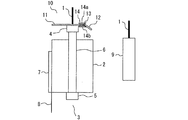
- FIG. 1 is a side view of a main part of an elevator to which the elevator air conditioning system according to the first embodiment is applied.
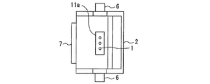
- FIG. 2 is a top view of a main part of an elevator to which the elevator air conditioning system according to the first embodiment is applied.
- the hoist (not shown) is provided in the hoistway or the machine room.
- the main rope 1 is wound around the hoist.
- the basket 2 is formed in a rectangular parallelepiped shape.
- the car 2 is provided inside the hoistway.
- the car frame 3 surrounds the car 2.
- the car frame 3 supports the car 2.
- the car frame 3 includes an upper frame 4, a lower frame 5, and a pair of vertical columns 6.
- the upper frame 4 is arranged above the car 2.
- the upper frame 4 is connected to one side of the main rope 1.
- the lower frame 5 is arranged below the car 2.
- One of the pair of vertical frames is arranged on the outside of one side of the car 2.
- One of the pair of vertical frames connects one side of the upper frame 4 and one side of the lower frame 5.
- the other side of the pair of vertical frames is arranged on the outside of the other side of the car 2.
- the other side of the pair of vertical frames connects the other side of the upper frame 4 and the other side of the lower frame 5.
- the door 7 is formed in a rectangular shape.
- the door 7 is provided on the side of the landing (not shown) in the car 2.
- the door 7 is provided so as to be able to open and close the doorway of the car 2.
- the apron 8 is attached to the lower edge of the car 2 just below the door 7.
- the apron 8 is attached for the purpose of preventing the user or the like from falling.
- the counterweight 9 is formed in a rectangular parallelepiped shape.
- the counterweight 9 is provided inside the hoistway.
- the counterweight 9 is arranged on the side opposite to the side of the landing (not shown) with respect to the car 2.
- the upper portion of the counterweight 9 is connected to the other side of the main rope 1.
- the wind conditioning system is installed above the car 2.
- the wind conditioning system is provided for the purpose of reducing the noise inside the car 2.
- the air conditioning system includes an upper air conditioning device 10.
- the upper wind regulating device 10 is provided above the car 2.
- the upper air conditioning device 10 includes an upper air conditioning cover 11, an upper movable body 12, an upper rotating shaft 13, and an upper urging body 14.
- the upper wind control cover 11 is formed in a rectangular shape.
- the upper wind control cover 11 is provided above the car 2 and away from the car 2.
- the upper air conditioning cover 11 is provided with a gap between it and the upper surface of the car 2.
- the upper air conditioning cover 11 is fixed to the upper frame 4.
- the upper air conditioning cover 11 is fixed to a structure other than the upper frame 4.
- the opening 11a is formed in the central portion of the upper air conditioning cover 11. The opening 11a is penetrated by the main rope 1.
- the upper movable body 12 is formed in a rectangular shape.
- the upper movable body 12 is adjacent to the edge of the upper wind control cover 11 on the opposite side of the landing.
- the upper rotation shaft 13 rotatably supports the central edge of the cage 2 of the upper movable body 12.
- the upper urging body 14 is provided around the adjacent portion of the upper air conditioning cover 11 and the upper movable body 12. Specifically, the upper urging body 14 includes a directly upper urging portion 14a and a directly lower urging portion 14b.
- the direct upper urging portion 14a is provided directly above the adjacent portions of the upper wind control cover 11 and the upper movable body 12.
- the direct downward urging portion 14b is provided directly below the adjacent portions of the upper wind control cover 11 and the upper movable body 12.
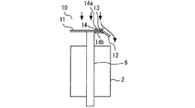
- FIG. 3 is a side view of a main part of an elevator to which the air conditioning system of the elevator according to the first embodiment is applied.
- the upper movable body 12 receives wind pressure.
- the upper movable body 12 rotates about the upper rotation shaft 13 due to the wind pressure.
- the upper movable body 12 is inclined so that the outer edge portion of the car 2 is lower than the central edge portion of the car 2.
- the rotation range of the upper movable body 12 is limited by the direct lower urging portion 14b of the upper urging body 14.
- FIG. 4 is a side view of a main part of the elevator to which the air conditioning system of the elevator according to the first embodiment is applied.
- the upper movable body 12 receives wind pressure.
- the upper movable body 12 rotates about the upper rotation shaft 13 due to the wind pressure.
- the upper movable body 12 is inclined so that the outer edge portion of the car 2 is above the central edge portion of the car 2.
- the rotation range of the upper movable body 12 is limited by the directly above urging portion 14a of the upper urging body 14.
- the upper air conditioning cover 11 is provided above the car 2 and away from the car 2.
- the upper movable body 12 is adjacent to the upper air conditioning cover 11.
- the upper movable body 12 is rotatably supported by the central edge of the car 2.
- the upper movable body 12 is tilted so that the outer edge of the car 2 is lower than the central edge of the car 2 when the car 2 is raised.
- the upper movable body 12 is tilted so that the outer edge of the car 2 is above the central edge of the car 2 when the car 2 is lowered. Therefore, with a simple configuration, it is possible to suppress noise inside the car 2 when the car 2 is raised and lowered.
- the upper movable body 12 is displaced in the direction of softening the wind pressure.
- the turbulence of the airflow around the car 2 is suppressed. Therefore, it is possible to suppress the generation of wind noise generated from the turbulent flow around the car 2. As a result, the noise inside the car 2 can be suppressed.
- the change in the cross-sectional area of the air passage is relatively gradual. Therefore, it is possible to suppress the increase in airflow. As a result, the noise inside the car 2 can be suppressed.
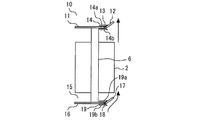
- Embodiment 2. 5 and 6 are side views of a main part of an elevator to which the elevator air conditioning system according to the second embodiment is applied.
- the same or corresponding parts as those of the first embodiment are designated by the same reference numerals. The explanation of this part is omitted.
- the air conditioning system of the second embodiment is a system in which the lower air conditioning device 15 is added to the air conditioning system of the first embodiment.
- the lower air conditioning device 15 includes a lower air conditioning cover 16, a lower movable body 17, a lower rotating shaft 18, and a lower urging body 19.
- the lower air conditioning cover 16, the lower movable body 17, the lower rotating shaft 18, and the lower urging body 19 are substantially the same as the upper air conditioning cover 11, the upper movable body 12, the upper rotating shaft 13, and the upper urging body 14. Has the function of.
- the lower air conditioning cover 16 is provided below the car 2 and away from the car 2.
- the lower air conditioning cover 16 is fixed to the lower frame 5.
- the lower air conditioning cover 16 is fixed to a structure other than the lower frame 5.
- the lower urging body 19 includes a direct urging portion 19a and a direct urging portion 19b.
- the direct upper urging portion 19a and the direct lower urging portion 19b have substantially the same functions as the direct upper urging portion 14a and the direct lower urging portion 14b.
- the air conditioning system includes an upper air conditioning device 10 and a lower air conditioning device 15. Therefore, with a simple configuration, it is possible to suppress noise inside the car 2 when the car 2 is raised and lowered.
- the upper movable body 12 and the lower movable body 17 are arranged inside the outer edge of the car 2 on the horizontal projection surface. Therefore, when the car 2 is ascended, the lower movable body 17 suppresses the generation of noise generated by the airflow separated from the car 2 colliding with the lower air conditioning cover 16. When the car 2 is descending, the upper movable body 12 suppresses the generation of noise generated by the airflow separated from the car 2 colliding with the upper air conditioning cover 11. As a result, the noise inside the car 2 can be suppressed more reliably.
- the upper air conditioning device 10 does not have to be provided. In this case, the same effect as that of the first embodiment can be obtained.
- Embodiment 3. 7 and 8 are side views of a main part of an elevator to which the elevator air conditioning system according to the third embodiment is applied.
- the same or corresponding parts as those of the second embodiment are designated by the same reference numerals. The explanation of this part is omitted.
- the air conditioning system of the third embodiment is a system in which the upper actuator 20 and the lower actuator 21 are added to the air conditioning system of the second embodiment.
- the upper actuator 20 is provided around the upper rotation shaft 13.
- the upper actuator 20 changes the amount of rotation of the upper rotation shaft 13 according to the ascending / descending speed of the car 2.
- the upper movable body 12 changes the inclination angle according to the ascending / descending speed of the car 2.
- the lower actuator 21 is provided around the lower rotating shaft 18.
- the lower actuator 21 changes the amount of rotation of the lower rotary shaft 18 according to the ascending / descending speed of the car 2.
- the lower movable body 17 changes the inclination angle according to the ascending / descending speed of the car 2.
- the wind conditioning system includes an upper actuator 20 and a lower actuator 21. Therefore, by not only relieving the wind pressure but also actively controlling the airflow around the car 2, the turbulence of the airflow around the car 2 can be suppressed more reliably.
- the upper actuator 20 and the lower actuator 21 may be interlocked with each other.
- the upper actuator 20 and the lower actuator 21 may be operated so that the rotation angle of the upper movable body 12 and the rotation angle of the lower movable body 17 match.
- the airflow around the entire cage 2 can be optimized. As a result, the noise inside the car 2 can be suppressed more reliably.
- FIG. 9 is a top view of a main part of an elevator to which the elevator air conditioning system according to the fourth embodiment is applied.
- FIG. 10 is a bottom view of a main part of an elevator to which the elevator air conditioning system according to the fourth embodiment is applied.
- the same or corresponding parts as those of the first embodiment are designated by the same reference numerals. The explanation of this part is omitted.
- the upper movable body 12 of the fourth embodiment includes a plurality of upper movable plates 12a.
- the plurality of upper movable plates 12a are provided side by side in the horizontal direction in parallel with the upper rotation shaft 13.
- the central edge portion of the car 2 is rotatably supported with respect to the upper rotating shaft 13.
- Each of the plurality of upper movable plates 12a is inclined so that the outer edge of the car 2 is lower than the central edge of the car 2 when the car 2 is raised.
- Each of the plurality of upper movable plates 12a is inclined so that the outer edge portion of the car 2 is above the central edge portion of the car 2 when the car 2 is lowered.
- the lower movable body 17 of the fourth embodiment includes a plurality of lower movable plates 17a.
- the plurality of lower movable plates 17a are provided side by side in the horizontal direction in parallel with the lower rotation shaft 18.
- the central edge portion of the car 2 is rotatably supported with respect to the lower rotating shaft 18.
- Each of the plurality of lower movable plates 17a is inclined so that the outer edge of the car 2 is lower than the central edge of the car 2 when the car 2 is raised.
- Each of the plurality of lower movable plates 17a is inclined so that the outer edge of the car 2 is above the central edge of the car 2 when the car 2 is lowered.
- the plurality of upper movable plates 12a are provided side by side in a direction parallel to the upper rotation shaft 13.
- the plurality of upper movable plates 12a rotate on the same rotation axis.
- the plurality of upper movable plates 12a can operate with a slight wind pressure.
- each of the plurality of upper movable plates 12a is displaced to the optimum position corresponding to the distribution of the wind pressure in the direction parallel to the rotation axis.
- the wind pressure is relieved. Therefore, the turbulence of the airflow around the car 2 can be suppressed more reliably. As a result, the noise inside the car 2 can be suppressed more reliably.
- the plurality of lower movable plates 17a can also operate with a slight wind pressure.
- each of the plurality of lower movable plates 17a is displaced to the optimum position corresponding to the distribution of the wind pressure in the direction parallel to the rotation axis.
- the wind pressure is relieved. Therefore, the turbulence of the airflow around the car 2 can be suppressed more reliably. As a result, the noise inside the car 2 can be suppressed more reliably.
- FIG. 11 is a top view of a main part of an elevator to which the elevator air conditioning system according to the fifth embodiment is applied.
- FIG. 12 is a bottom view of a main part of an elevator to which the elevator air conditioning system according to the fifth embodiment is applied.
- the same or corresponding parts as those of the fourth embodiment are designated by the same reference numerals. The explanation of this part is omitted.
- the air conditioning system of the fifth embodiment is a system in which the upper connecting body 22 and the lower connecting body 23 are added to the air conditioning system of the fourth embodiment.
- the upper connecting body 22 connects a plurality of upper movable plates 12a.
- the lower connecting body 23 connects a plurality of lower movable plates 17a.
- the upper connecting body 22 connects a plurality of upper movable plates 12a. Therefore, it is possible to suppress noise generated by the plurality of upper movable plates 12a fluttering due to minute fluctuations in wind pressure.
- the lower connecting body 23 connects a plurality of lower movable plates 17a. Therefore, it is possible to suppress noise generated by the plurality of lower movable plates 17a fluttering due to minute fluctuations in wind pressure.
- Embodiment 6. 13 and 14 are front views of a main part of an elevator to which the elevator air conditioning system according to the sixth embodiment is applied.
- the same or corresponding parts as those of the first embodiment are designated by the same reference numerals. The explanation of this part is omitted.
- the counterweight 9 moves up and down on one side of the car 2.
- the upper air conditioning device 10 includes an upper air conditioning cover 11, a pair of upper movable bodies 12, a pair of upper rotating shafts 13, and an upper connecting body 25.
- the upper air conditioning cover 11 is provided with a gap between the upper surface of the car 2 and the upper surface of the car 2 via a pair of upper columns 24.
- One of the pair of upper movable bodies 12 is adjacent to the edge of the upper air conditioning cover 11 on one side of the car 2 as the main movable body.
- the other side of the pair of upper movable bodies 12 is adjacent to the edge of the upper air conditioning cover 11 on the other side of the car 2 as a slave movable body.
- the surface area of the other of the pair of upper movable bodies 12 is smaller than the surface area of one of the pair of upper movable bodies 12.
- One of the pair of upper rotating shafts 13 rotatably supports the central edge of the car 2 in one of the pair of upper movable bodies 12.
- the other of the pair of upper rotating shafts 13 rotatably supports the central edge of the car 2 on the other of the pair of upper movable bodies 12.
- the upper connecting body 25 is arranged above the upper air conditioning cover 11.
- the upper connecting body 25 is a wire.
- One side of the upper connecting body 25 is connected to the surface of one of the pair of upper movable bodies 12 opposite to the car 2.
- the other side of the upper connecting body 25 is connected to the surface of the other side of the pair of upper movable bodies 12 opposite to the car 2.
- the lower air conditioning device 15 includes a lower air conditioning cover 16, a pair of lower movable bodies 17, a pair of lower rotating shafts 18, and a lower connecting body 27.
- the lower air conditioning cover 16 is provided with a gap between it and the lower surface of the car 2 via a pair of lower columns 26.
- One of the pair of lower movable bodies 17 is adjacent to the edge of the lower wind control cover 16 on one side of the car 2 as the main movable body.
- the other of the pair of lower movable bodies 17 is adjacent to the edge of the lower wind control cover 16 on the other side of the car 2 as a slave movable body.
- the surface area of the other of the pair of lower movable bodies 17 is smaller than the surface area of one of the pair of lower movable bodies 17.
- One of the pair of lower rotating shafts 18 rotatably supports the central edge of the car 2 in one of the pair of lower movable bodies 17.
- the other of the pair of lower rotating shafts 18 rotatably supports the central edge of the car 2 on the other of the pair of lower movable bodies 17.
- the lower connecting body 27 is arranged below the lower air conditioning cover 16.
- the lower connecting body 27 is a wire.
- One side of the lower connecting body 27 is connected to the surface of one of the pair of lower movable bodies 17 opposite to the car 2.
- the other side of the lower connecting body 27 is connected to the surface of the other side of the pair of lower movable bodies 17 opposite to the car 2.
- the wind pressure received by one of the pair of upper movable bodies 12 when the car 2 is ascended is larger than the wind pressure received by the other of the pair of upper movable bodies 12.
- one of the pair of upper movable bodies 12 is inclined so that the outer edge portion of the car 2 is lower than the central edge portion of the car 2.
- the other of the pair of upper movable bodies 12 is interlocked with one of the pair of upper movable bodies 12 via the upper connecting body 25, so that the outer edge of the car 2 becomes the central edge of the car 2. Tilt so that it is above.
- the pair of upper movable bodies 12 are interlocked with each other to guide the air around the upper part of the car 2 to the side of the counterweight 9. .
- the pair of lower movable bodies 17 are interlocked with each other to guide the air around the lower part of the car 2 to the side of the counterweight 9.
- the side from the car 2 to the landing is narrower than the side from the car 2 to the other side. Therefore, it is possible to suppress the wind noise generated by the air flow passing through a narrow space. As a result, the noise inside the car 2 can be suppressed.
- At least one of the upper air conditioning device 10 and the lower air conditioning device 15 of the sixth embodiment may be applied to an elevator in which the counterweight 9 moves up and down the back side of the car 2.
- FIG. 15 is a front view of an elevator car to which the elevator air conditioning system according to the seventh embodiment is applied.
- the same or corresponding parts as those of the first embodiment are designated by the same reference numerals. The explanation of this part is omitted.
- the upper air conditioning cover 11 includes a first upper movable portion 11b, a second upper movable portion 11c, and an upper fixing portion 11d.
- the first upper movable portion 11b is provided above the left portion of the car 2.
- the second upper movable portion 11c is provided above the right portion of the car 2.
- the upper fixing portion 11d is provided above the central portion in the left-right direction of the car 2.
- the upper fixed portion 11d is provided between the first upper movable portion 11b and the second upper movable portion 11c.
- the upper fixing portion 11d is fixed to the upper frame 4.
- the central edge portion of the car 2 is rotatably attached to the edge portion of the upper fixed portion 11d.
- the central edge portion of the car 2 is rotatably attached to the edge portion of the upper fixed portion 11d by a rotation shaft.
- the first upper movable portion 11b is provided so that the outer edge portion of the car 2 can rise upward by rotating around the central edge portion of the car 2.
- the central edge portion of the car 2 is rotatably attached to the edge portion of the upper fixed portion 11d.
- the central edge portion of the car 2 is rotatably attached to the edge portion of the upper fixed portion 11d by a rotation shaft.
- the second upper movable portion 11c is provided so that the outer edge portion of the car 2 can rise upward by rotating around the central edge portion of the car 2.
- the upper wind regulating device 10 is brought closer to the upper part of the car 2 above the car 2. Specifically, the first upper movable portion 11b and the second upper movable portion 11c are maintained in a state of being arranged on the same plane as the upper fixed portion 11d.
- the upper air conditioner 10 is moved away from the car 2 above the car 2. Specifically, the first upper movable portion 11b and the second upper movable portion 11c are maintained in a state in which the outer edge portion of the car 2 stands up upward.
- the upper wind regulating device 10 is brought closer to the upper part of the car 2 above the car 2 during the normal operation of the elevator. Therefore, even if the height of the top of the hoistway is lowered, a gap can be secured between the upper air conditioning device 10 and the top of the hoistway when the car 2 moves to the highest position.
- the upper air conditioning device 10 keeps the upper air conditioning device 10 away from the car 2 above the car 2. Therefore, more work space in the height direction can be secured directly above the car 2. As a result, the worker can easily maintain the elevator directly above the car 2.
- a stopper for an upper air conditioning cover may be provided to limit the rotation of the first upper movable portion 11b and the second upper movable portion 11c.
- the stopper for the upper wind control cover maintains the first upper movable portion 11b and the second upper movable portion 11c in the state before being raised upward and the state after being raised upward. Therefore, the upper air conditioning device 10 can be maintained in an appropriate state at each time of normal operation and maintenance of the elevator.
- an upper air conditioning cover urging body may be provided to urge the first upper movable portion 11b and the second upper movable portion 11c in the rotational direction in which the outer edge portion of the car 2 rises upward. .. In this case, during maintenance of the elevator, it is possible to reduce the force when the worker raises the outer edge of the car 2 in the first upper movable portion 11b and the second upper movable portion 11c.
- each of the first upper movable portion 11b and the second upper movable portion 11c may be further divided. In this case, each of the divided first upper movable portion 11b and the second upper movable portion 11c may be independently rotatable by the rotation axis.
- FIG. 16 is a front view of an elevator car to which the elevator air conditioning system according to the eighth embodiment is applied.
- the same or corresponding parts as those of the first embodiment are designated by the same reference numerals. The explanation of this part is omitted.
- the upper wind regulating device 10 includes a plurality of upper elevating supports 11e.
- the plurality of upper elevating supports 11e are provided side by side in the width direction of the car 2 above the car 2.
- the plurality of upper elevating supports 11e are fixed to the upper surface of the upper frame 4.
- each of the plurality of upper elevating supports 11e is a foldable column.
- the plurality of upper elevating supports 11e support the upper air conditioning cover 11 with a gap between them and the upper surface of the car 2.
- the plurality of upper elevating supports 11e support the upper air conditioning cover 11 so as to be movable in the vertical direction.
- the upper wind regulating device 10 is brought closer to the upper part of the car 2 above the car 2. Specifically, by folding each of the plurality of upper elevating supports 11e, the upper air conditioning cover 11 is maintained in a state of being arranged directly above the upper frame 4.
- the upper air conditioner 10 is moved above the car 2 and away from the upper part of the car 2. Specifically, each of the plurality of upper elevating supports 11e becomes linear due to the release from folding, so that the upper air conditioning cover 11 is maintained in a state of having a gap between the upper elevating support 11e and the upper frame 4.
- the upper wind regulating device 10 is brought closer to the upper part of the car 2 above the car 2 during the normal operation of the elevator. Therefore, even if the height of the top of the hoistway is lowered, a gap can be secured between the upper air conditioning device 10 and the top of the hoistway when the car 2 moves to the highest position.
- the upper air conditioning device 10 keeps the upper air conditioning device 10 away from the upper part of the car 2 above the car 2. Therefore, more work space in the height direction can be secured directly above the car 2. As a result, the worker can easily maintain the elevator directly above the car 2.
- a stopper for the upper air conditioning device may be provided to limit the vertical movement of the upper air conditioning device 10. In this case, if the upper air conditioner stopper maintains the state before the upper air conditioner 10 is moved upward and the state after the upper air conditioner 10 is moved upward, during normal operation and maintenance of the elevator. At each of these times, the upper air conditioning device 10 can be maintained in an appropriate state.
- an urging body for an upper rectifying device may be provided to urge the upper rectifying cover 11 upward. In this case, it is possible to reduce the force when the worker moves the upper wind control cover 11 upward during the maintenance of the elevator.
- the upper air conditioning device 10 may be divided. In this case, each of the divided upper air conditioning devices 10 may be independently movable in the vertical direction by the upper elevating support 11e.
- FIG. 17 is a side view of an elevator car to which the elevator air conditioning system according to the ninth embodiment is applied.
- the same or corresponding parts as those of the first embodiment are designated by the same reference numerals. The explanation of this part is omitted.
- the lower wind control cover 16 includes a first lower movable portion 16a, a second lower movable portion 16b, and a lower fixing portion 16c.
- the first lower movable portion 16a is provided below the front portion of the car 2.
- the second lower movable portion 16b is provided below the rear portion of the car 2.
- the lower fixing portion 16c is provided below the central portion in the front-rear direction of the car 2.
- the lower fixing portion 16c is provided between the first lower movable portion 16a and the second lower movable portion 16b.
- the lower fixing portion 16c is fixed to the lower frame 5.
- the central edge portion of the car 2 is rotatably attached to the edge portion of the lower fixed portion 16c.
- the central edge portion of the car 2 is rotatably attached to the edge portion of the lower fixed portion 16c by a rotation shaft.
- the first lower movable portion 16a is provided so that the outer edge portion of the car 2 can hang down by rotating around the center side edge portion of the car 2.
- the central edge portion of the car 2 is rotatably attached to the edge portion of the lower fixed portion 16c.
- the central edge portion of the car 2 is rotatably attached to the edge portion of the lower fixed portion 16c by a rotation shaft.
- the second lower movable portion 16b is provided so that the outer edge portion of the car 2 can hang down by rotating around the center side edge portion of the car 2.
- the lower air conditioner 15 is brought closer to the lower part of the car 2 below the car 2. Specifically, the first lower movable portion 16a and the second lower movable portion 16b are maintained in a state of being arranged on the same plane as the lower fixing portion 16c.
- the lower air conditioner 15 is kept away from the car 2 below the car 2. Specifically, the first lower movable portion 16a and the second lower movable portion 16b are maintained in a state in which the outer edge portion of the car 2 hangs downward.
- the lower air conditioning device 15 is brought closer to the lower part of the car 2 below the car 2 during the normal operation of the elevator. Therefore, even if the depth of the bottom of the hoistway is made shallow, a gap can be secured between the lower air conditioning device 15 and the bottom of the hoistway when the car 2 moves to the lowest position.
- the lower air conditioning device 15 is kept away from the car 2 below the car 2. Therefore, more work space in the height direction can be secured directly under the car 2. As a result, the worker can easily perform maintenance of the elevator directly under the car 2.
- a stopper for the lower air conditioning cover that limits the rotation of the first lower movable portion 16a and the second lower movable portion 16b may be provided.
- the first lower movable portion 16a and the second lower movable portion 16b are in a state before being hung downward and a state after being hung downward by the stopper for the lower wind control cover. If it is maintained at, the lower air conditioning device 15 can be maintained in an appropriate state at each time of normal operation and maintenance of the elevator.
- first lower movable portion 16a and the second lower movable portion 16b are provided with a lower wind control cover that urges the first lower movable portion 16a and the second lower movable portion 16b in the rotational direction in which the edge portion farther from the lower fixing portion 16c rises upward.
- a stance may be provided. In this case, during maintenance of the elevator, the force when the worker raises the edge portion of the first lower movable portion 16a and the second lower movable portion 16b far from the lower fixing portion 16c is reduced. can do.
- each of the first lower movable portion 16a and the second lower movable portion 16b may be further divided.
- each of the divided first lower movable portion 16a and the second lower movable portion 16b may be independently rotatable by the rotation axis.
- FIG. 18 is a side view of an elevator car to which the elevator air conditioning system according to the tenth embodiment is applied.
- the same or corresponding parts as those of the first embodiment are designated by the same reference numerals. The explanation of this part is omitted.
- the lower air conditioning device 15 includes a plurality of lower elevating supports 16e.
- the plurality of lower elevating supports 16e are provided side by side in the depth direction of the car 2 below the car 2.
- the plurality of lower elevating supports 16e are fixed to the lower frame 5.
- each of the plurality of lower elevating supports 16e is a stretchable support.
- the plurality of lower elevating supports 16e support the lower air conditioning cover 16 with a gap between them and the lower surface of the car 2.
- the plurality of lower elevating supports 16e support the lower air conditioning cover 16 so as to be movable in the vertical direction.
- the lower air conditioner 15 is brought closer to the lower part of the car 2 below the car 2. Specifically, by contracting each of the plurality of lower elevating supports 16e, the lower air conditioning cover 16 is maintained in a state of being arranged directly under the lower frame 5.
- the lower air conditioning device 15 is kept away from the lower part of the car 2 under the car 2. Specifically, by extending each of the plurality of lower elevating supports 16e, the lower air conditioning cover 16 is maintained in a state of having a gap between the lower elevating support 16e and the lower frame 5.
- the lower air conditioning device 15 is brought closer to the lower part of the car 2 below the car 2 during the normal operation of the elevator. Therefore, even if the depth of the bottom of the hoistway is made shallow, a gap can be secured between the lower air conditioning device 15 and the bottom of the hoistway when the car 2 moves to the lowest position.
- the lower air conditioning device 15 is kept away from the car 2 below the car 2. Therefore, more work space in the height direction can be secured directly under the car 2. As a result, the worker can easily perform maintenance of the elevator directly under the car 2.
- a stopper for the lower air conditioning device may be provided to limit the vertical movement of the lower air conditioning device 15. In this case, if the lower air conditioner stopper maintains the state before the lower air conditioner 15 is moved upward and the state after the lower air conditioner 15 is moved upward, it will be the same as during normal operation of the elevator.
- the lower air conditioning device 15 can be maintained in an appropriate state at each time of maintenance.
- an urging body for the lower air conditioning device may be provided to urge the lower air conditioning device 15 upward. In this case, it is possible to reduce the force when the worker moves the lower air conditioning cover 16 upward during the maintenance of the elevator.
- the lower air conditioning device 15 may be divided. In this case, each of the divided lower air conditioning devices 15 may be independently movable in the vertical direction by the lower elevating support 16e.
- the elevator air conditioning system disclosed in this disclosure can be used for the elevator system.
Landscapes
- Engineering & Computer Science (AREA)
- Automation & Control Theory (AREA)
- Civil Engineering (AREA)
- Mechanical Engineering (AREA)
- Structural Engineering (AREA)
- Cage And Drive Apparatuses For Elevators (AREA)
Abstract
かごの昇降時において、かごの内部の騒音を抑制することができるエレベーターの整風システムを提供する。エレベーターの監視装置は、を備えた。本開示に係るエレベーターの整風システムは、エレベーターのかごの上方または下方において前記かごから離れて設けられた整風カバーと、前記整風カバーに隣接し、前記かごの中央側の縁部が回転自在に支持され、前記かごが上昇している際に前記かごの外側の縁部が前記かごの中央側の縁部よりも下方となるように傾斜し、前記かごが下降している際に前記かごの外側の縁部が前記かごの中央側の縁部よりも上方となるように傾斜する可動体と、を備えた。
Description
本開示は、エレベーター整風システムに関する。
特許文献1は、エレベーターの整風システムを開示する。当該整風システムによれば、かごの内部の騒音を抑制し得る。
しかしながら、特許文献1に記載の整風システムの形状は複雑である。このため、整風システムの加工費および据付費が高くなる。
本開示は、上述の課題を解決するためになされた。本開示の目的は、簡単な構成で、かごの昇降時において、かごの内部の騒音を抑制することができるエレベーターの整風システムを提供することである。
本開示に係るエレベーターの整風システムは、エレベーターのかごの上方または下方において前記かごから離れて設けられた整風カバーと、前記整風カバーに隣接し、前記かごの中央側の縁部が回転自在に支持され、前記かごが上昇している際に前記かごの外側の縁部が前記かごの中央側の縁部よりも下方となるように傾斜し、前記かごが下降している際に前記かごの外側の縁部が前記かごの中央側の縁部よりも上方となるように傾斜する可動体と、を備えた。
本開示に係るエレベーターの整風システムは、エレベーターのかごの上方において前記かごから離れて設けられた整風カバーと、前記かごの一側において前記整風カバーの縁部に隣接し、前記かごの中央側の縁部が回転自在に支持された主可動体と、前記かごの他側において前記整風カバーの縁部に隣接し、前記かごの中央側の縁部が回転自在に支持され、前記主可動体の表面積よりも小さい表面積を有した従可動体と、前記主可動体と前記従可動体とに対して前記かごとは反対側に設けられ、前記主可動体と前記従可動体とに連結された連結体と、を備え、前記主可動体は、前記かごが上昇している際の風圧で前記かごの外側の縁部が前記かごの中央側の縁部よりも下方となるように傾斜し、前記従可動体は、前記かごが上昇している際に前記連結体を介して前記主可動体に連動することで、前記かごの外側の縁部が前記かごの中央側の縁部よりも上方となるように傾斜する。
本開示に係るエレベーターの整風システムは、エレベーターのかごの下方において前記かごから離れて設けられた整風カバーと、前記かごの一側において前記整風カバーの縁部に隣接し、前記かごの中央側の縁部が回転自在に支持された主可動体と、前記かごの他側において前記整風カバーの縁部に隣接し、前記かごの中央側の縁部が回転自在に支持され、前記主可動体の表面積よりも小さい表面積を有した従可動体と、前記主可動体と前記従可動体とに対して前記かごとは反対側に設けられ、前記主可動体と前記従可動体とに連結された連結体と、を備え、前記主可動体は、前記かごが下降している際の風圧で前記かごの外側の縁部が前記かごの中央側の縁部よりも上方となるように傾斜し、前記従可動体は、前記かごが下降している際に前記連結体を介して前記主可動体に連動することで、前記かごの外側の縁部が前記かごの中央側の縁部よりも下方となるように傾斜する。
本開示に係るエレベーターの整風システムは、エレベーターのかごの上方において前記かごから離れて設けられた上側整風カバーと、前記かごの下方において前記かごから離れて設けられた下側整風カバーと、前記上側整風カバーに隣接し、前記かごの中央側の縁部が回転自在に支持され、前記かごが上昇している際に前記かごの外側の縁部が前記かごの中央側の縁部よりも下方となるように傾斜し、前記かごが下降している際に前記かごの外側の縁部が前記かごの中央側の縁部よりも上方となるように傾斜する上側可動体と、前記下側整風カバーに隣接し、前記かごの中央側の縁部が回転自在に支持され、前記かごが上昇している際に前記かごの外側の縁部が前記かごの中央側の縁部よりも下方となるように傾斜し、前記かごが下降している際に前記かごの外側の縁部が前記かごの中央側の縁部よりも上方となるように傾斜する下側可動体と、を備えた。
本開示によれば、上側可動体は、かごの中央側の縁部が回転自在に支持される。上側可動体は、かごが上昇している際にかごの外側の縁部がかごの中央側の縁部よりも下方となるように傾斜する。可動体は、かごが下降している際にかごの外側の縁部がかごの中央側の縁部よりも上方となるように傾斜する。このため、簡単な構成で、かごの昇降時において、かごの内部の騒音を抑制することができる。
実施の形態について添付の図面に従って説明する。なお、各図中、同一または相当する部分には同一の符号が付される。当該部分の重複説明は適宜に簡略化ないし省略する。
実施の形態1.
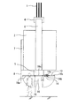
図1は実施の形態1におけるエレベーターの整風システムが適用されるエレベーターの要部の側面図である。図2は実施の形態1におけるエレベーターの整風システムが適用されるエレベーターの要部の上面図である。
図1は実施の形態1におけるエレベーターの整風システムが適用されるエレベーターの要部の側面図である。図2は実施の形態1におけるエレベーターの整風システムが適用されるエレベーターの要部の上面図である。
図1と図2とのエレベーターにおいて、図示されない巻上機は、昇降路または機械室に設けられる。主ロープ1は、巻上機に巻き掛けられる。
かご2は、直方体状に形成される。かご2は、昇降路の内部に設けられる。かご枠3は、かご2を囲む。かご枠3は、かご2を支持する。具体的には、かご枠3は、上枠4と下枠5と一対の縦柱6とを備える。上枠4は、かご2の上方に配置される。上枠4は、主ロープ1の一側に連結される。下枠5は、かご2の下方に配置される。一対の縦枠の一方は、かご2の一側の外方に配置される。一対の縦枠の一方は、上枠4の一側と下枠5の一側とを連結する。一対の縦枠の他方は、かご2の他側の外方に配置される。一対の縦枠の一他方は、上枠4の他側と下枠5の他側とを連結する。
ドア7は、矩形状に形成される。ドア7は、かご2における図示されない乗場の側に設けられる。ドア7は、かご2の出入口を開閉し得るように設けられる。エプロン8は、ドア7の直下においてかご2の下縁部に取り付けられる。エプロン8は、利用者等の落下防止を目的として取り付けられる。
カウンターウェイト9は、直方体状に形成される。カウンターウェイト9は、昇降路の内部に設けられる。カウンターウェイト9は、かご2に対して図示されない乗場の側とは反対側に配置される。カウンターウェイト9の上部は、主ロープ1の他側に連結される。
例えば、整風システムは、かご2の上方に設けられる。整風システムは、かご2の内部の騒音の低減を目的として設けられる。整風システムは、上側整風装置10を備える。上側整風装置10は、かご2の上方に設けられる。上側整風装置10は、上側整風カバー11と上側可動体12と上側回転軸13と上側付勢体14とを備える。
上側整風カバー11は、矩形状に形成される。上側整風カバー11は、かご2の上方においてかご2から離れて設けられる。上側整風カバー11は、かご2の上面との間に隙間をあけて設けられる。例えば、上側整風カバー11は、上枠4に固定される。例えば、上側整風カバー11は、上枠4以外の構造物に固定される。開口部11aは、上側整風カバー11の中央部に形成される。開口部11aは、主ロープ1に貫通される。
上側可動体12は、矩形状に形成される。上側可動体12は、上側整風カバー11における乗場と反対側の縁部に隣接する。
上側回転軸13は、上側可動体12のかご2の中央側の縁部を回転自在に支持する。
上側付勢体14は、上側整風カバー11と上側可動体12との互いの隣接部の周囲に設けられる。具体的には、上側付勢体14は、直上付勢部14aと直下付勢部14bとを備える。直上付勢部14aは、上側整風カバー11と上側可動体12との互いの隣接部の直上に設けられる。直下付勢部14bは、上側整風カバー11と上側可動体12との互いの隣接部の直下に設けられる。
次に、図3を用いて、かご2が上昇している際の整風システムの動作を説明する。
図3は実施の形態1におけるエレベーターの整風システムが適用されるエレベーターの要部の側面図である。
図3は実施の形態1におけるエレベーターの整風システムが適用されるエレベーターの要部の側面図である。
図3において、巻上機が一方向に回転すると、主ロープ1は、巻上機の回転に追従して移動する。かご2は、主ロープ1の移動に追従して上昇する。カウンターウェイト9は、主ロープ1の移動に追従して下降する。
この際、整風システムにおいて、上側可動体12は、風圧を受ける。上側可動体12は、当該風圧により上側回転軸13を軸として回転する。その結果、上側可動体12は、かご2の外側の縁部がかご2の中央側の縁部よりも下方となるように傾斜する。この際、上側可動体12の回転範囲は、上側付勢体14の直下付勢部14bにより制限される。
次に、図4を用いて、かご2が下降している際の整風システムの動作を説明する。
図4は実施の形態1におけるエレベーターの整風システムが適用されるエレベーターの要部の側面図である。
図4は実施の形態1におけるエレベーターの整風システムが適用されるエレベーターの要部の側面図である。
図4において、巻上機が他方向に回転すると、主ロープ1は、巻上機の回転に追従して移動する。かご2は、主ロープ1の移動に追従して下降する。カウンターウェイト9は、主ロープ1の移動に追従して上昇する。
この際、整風システムにおいて、上側可動体12は、風圧を受ける。上側可動体12は、当該風圧により上側回転軸13を軸として回転する。その結果、上側可動体12は、かご2の外側の縁部がかご2の中央側の縁部よりも上方となるように傾斜する。この際、上側可動体12の回転範囲は、上側付勢体14の直上付勢部14aにより制限される。
以上で説明した実施の形態1によれば、上側整風カバー11は、かご2の上方においてかご2から離れて設けられる。上側可動体12は、上側整風カバー11に隣接する。上側可動体12は、かご2の中央側の縁部が回転自在に支持される。上側可動体12は、かご2が上昇している際にかご2の外側の縁部がかご2の中央側の縁部よりも下方となるように傾斜する。上側可動体12は、かご2が下降している際にかご2の外側の縁部がかご2の中央側の縁部よりも上方となるように傾斜する。このため、簡単な構成で、かご2の昇降時において、かご2の内部の騒音を抑制することができる。
また、図3と図4とに示されるように、上側可動体12は、風圧を和らげる方向に変位する。この場合、かご2の周りの気流の乱れが抑制される。このため、かご2の周りの乱れた流れから生じる風切音の発生を抑制することができる。その結果、かご2の内部の騒音を抑制することができる。
実施の形態1のかご2の上部において、風路の断面積の変化は比較的緩やかである。このため、気流の速くなることを抑制できる。その結果、かご2の内部の騒音を抑制することができる。
実施の形態2.
図5と図6とは実施の形態2におけるエレベーターの整風システムが適用されるエレベーターの要部の側面図である。なお、実施の形態1の部分と同一又は相当部分には同一符号が付される。当該部分の説明は省略される。
図5と図6とは実施の形態2におけるエレベーターの整風システムが適用されるエレベーターの要部の側面図である。なお、実施の形態1の部分と同一又は相当部分には同一符号が付される。当該部分の説明は省略される。
図5と図6とに示されるように、実施の形態2の整風システムは、実施の形態1の整風システムに対して下側整風装置15が付加されたシステムである。
下側整風装置15は、下側整風カバー16と下側可動体17と下側回転軸18と下側付勢体19とを備える。下側整風カバー16と下側可動体17と下側回転軸18と下側付勢体19とは、上側整風カバー11と上側可動体12と上側回転軸13と上側付勢体14とほぼ同等の機能を有する。
ただし、下側整風カバー16は、かご2の下方においてかご2から離れて設けられる。例えば、下側整風カバー16は、下枠5に固定される。例えば、下側整風カバー16は、下枠5以外の構造物に固定される。
下側付勢体19は、直上付勢部19aと直下付勢部19bとを備える。直上付勢部19aと直下付勢部19bとは、直上付勢部14aと直下付勢部14bとほぼ同等の機能を有する。
以上で説明した実施の形態2によれば、整風システムは、上側整風装置10と下側整風装置15とを備える。このため、簡単な構成で、かご2の昇降時において、かご2の内部の騒音を抑制することができる。
なお、上側可動体12と下側可動体17とは、水平投影面上においてかご2の外縁部よりも内側に配置される。このため、かご2の上昇時において、下側可動体17は、かご2からはく離した気流が下側整風カバー16に衝突することで生じる騒音の発生を抑制する。かご2の下降時において、上側可動体12は、かご2からはく離した気流が上側整風カバー11に衝突することで生じる騒音の発生を抑制する。その結果、かご2の内部の騒音をより確実に抑制することができる。
また、上側整風装置10がなくてもよい。この場合、実施の形態1と同様の効果を得ることができる。
実施の形態3.
図7と図8とは実施の形態3におけるエレベーターの整風システムが適用されるエレベーターの要部の側面図である。なお、実施の形態2の部分と同一又は相当部分には同一符号が付される。当該部分の説明は省略される。
図7と図8とは実施の形態3におけるエレベーターの整風システムが適用されるエレベーターの要部の側面図である。なお、実施の形態2の部分と同一又は相当部分には同一符号が付される。当該部分の説明は省略される。
図7と図8とに示されるように、実施の形態3の整風システムは、実施の形態2の整風システムに対して上側アクチュエーター20と下側アクチュエーター21とが付加されたシステムである。
上側アクチュエーター20は、上側回転軸13の周囲に設けられる。上側アクチュエーター20は、かご2の昇降速度に応じて上側回転軸13の回転量を変化させる。その結果、上側可動体12は、かご2の昇降速度に応じて傾斜角度を変化させる。
下側アクチュエーター21は、下側回転軸18の周囲に設けられる。下側アクチュエーター21は、かご2の昇降速度に応じて下側回転軸18の回転量を変化させる。その結果、下側可動体17は、かご2の昇降速度に応じて傾斜角度を変化させる。
以上で説明した実施の形態3によれば、整風システムは、上側アクチュエーター20と下側アクチュエーター21とを備える。このため、風圧を和らげるだけでなく、かご2の周囲の気流を能動的に制御することで、かご2の周りの気流の乱れをより確実に抑制することができる。
この際、上側アクチュエーター20と下側アクチュエーター21とを連動させてもよい。例えば、前記上側可動体12の回転角度と前記下側可動体17の回転角度とが一致するように、上側アクチュエーター20と下側アクチュエーター21とを動作させてもよい。この場合、かご2の全体の周囲の気流を最適にすることができる。その結果、かご2の内部の騒音をより確実に抑制することができる。
なお、上側整風装置10と下側整風装置15とのうちのいずれか一方がなくてもよい。この場合も、かご2の周囲の気流を能動的に制御することで、かご2の周りの気流の乱れを抑制することができる。
実施の形態4.
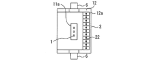
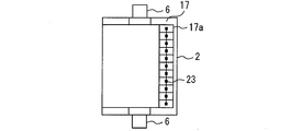
図9は実施の形態4におけるエレベーターの整風システムが適用されるエレベーターの要部の上面図である。図10は実施の形態4におけるエレベーターの整風システムが適用されるエレベーターの要部の底面図である。なお、実施の形態1の部分と同一又は相当部分には同一符号が付される。当該部分の説明は省略される。
図9は実施の形態4におけるエレベーターの整風システムが適用されるエレベーターの要部の上面図である。図10は実施の形態4におけるエレベーターの整風システムが適用されるエレベーターの要部の底面図である。なお、実施の形態1の部分と同一又は相当部分には同一符号が付される。当該部分の説明は省略される。
図9に示されるように、実施の形態4の上側可動体12は、複数の上側可動板12aを備える。複数の上側可動板12aは、上側回転軸13と平行に水平方向に並んで設けられる。複数の上側可動板12aの各々は、かご2の中央側の縁部が上側回転軸13に対して回転自在に支持される。複数の上側可動板12aの各々は、かご2が上昇している際にかご2の外側の縁部がかご2の中央側の縁部よりも下方となるように傾斜する。複数の上側可動板12aの各々は、かご2が下降している際にかご2の外側の縁部がかご2の中央側の縁部よりも上方となるように傾斜する。
図10に示されるように、実施の形態4の下側可動体17は、複数の下側可動板17aを備える。複数の下側可動板17aは、下側回転軸18と平行に水平方向に並んで設けられる。複数の下側可動板17aの各々は、かご2の中央側の縁部が下側回転軸18に対して回転自在に支持される。複数の下側可動板17aの各々は、かご2が上昇している際にかご2の外側の縁部がかご2の中央側の縁部よりも下方となるように傾斜する。複数の下側可動板17aの各々は、かご2が下降している際にかご2の外側の縁部がかご2の中央側の縁部よりも上方となるように傾斜する。
以上で説明した実施の形態4によれば、複数の上側可動板12aは、上側回転軸13と平行な方向に並んで設けられる。複数の上側可動板12aは、同一の回転軸で回転する。この際、複数の上側可動板12aは、わずかな風圧で動作し得る。この場合、回転軸に平行な方向の風圧の分布に対応して、複数の上側可動板12aの各々は、最適な位置に変位する。その結果、風圧が和らげられる。このため、かご2の周りの気流の乱れをより確実に抑制することができる。その結果、かご2の内部の騒音をより確実に抑制することができる。
また、複数の下側可動板17aも、わずかな風圧で動作し得る。この場合、回転軸に平行な方向の風圧の分布に対応して、複数の下側可動板17aの各々は、最適な位置に変位する。その結果、風圧が和らげられる。このため、かご2の周りの気流の乱れをより確実に抑制することができる。その結果、かご2の内部の騒音をより確実に抑制することができる。
なお、上側整風装置10と下側整風装置15とのうちのいずれか一方がなくてもよい。この場合も、かご2の周りの気流の乱れをより確実に抑制することができる。その結果、かご2の内部の騒音をより確実に抑制することができる。
実施の形態5.
図11は実施の形態5におけるエレベーターの整風システムが適用されるエレベーターの要部の上面図である。図12は実施の形態5におけるエレベーターの整風システムが適用されるエレベーターの要部の底面図である。なお、実施の形態4の部分と同一又は相当部分には同一符号が付される。当該部分の説明は省略される。
図11は実施の形態5におけるエレベーターの整風システムが適用されるエレベーターの要部の上面図である。図12は実施の形態5におけるエレベーターの整風システムが適用されるエレベーターの要部の底面図である。なお、実施の形態4の部分と同一又は相当部分には同一符号が付される。当該部分の説明は省略される。
図11と図12とに示されるように、実施の形態5の整風システムは、実施の形態4の整風システムに対して上側接続体22と下側接続体23とが付加されたシステムである。
上側接続体22は、複数の上側可動板12aを接続する。
下側接続体23は、複数の下側可動板17aを接続する。
以上で説明した実施の形態4によれば、上側接続体22は、複数の上側可動板12aを接続する。このため、複数の上側可動板12aが風圧の微小な変動を受けてばたつくことで生じる騒音を抑制することができる。
また、下側接続体23は、複数の下側可動板17aを接続する。このため、複数の下側可動板17aが風圧の微小な変動を受けてばたつくことで生じる騒音を抑制することができる。
なお、上側整風装置10と下側整風装置15とのうちのいずれか一方がなくてもよい。この場合も、複数の上側可動板12aまたは複数の下側可動板17aが風圧の微小な変動を受けてばたつくことで生じる騒音を抑制することができる。
実施の形態6.
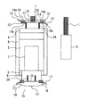
図13と図14とは実施の形態6におけるエレベーターの整風システムが適用されるエレベーターの要部の正面図である。なお、実施の形態1の部分と同一又は相当部分には同一符号が付される。当該部分の説明は省略される。
図13と図14とは実施の形態6におけるエレベーターの整風システムが適用されるエレベーターの要部の正面図である。なお、実施の形態1の部分と同一又は相当部分には同一符号が付される。当該部分の説明は省略される。
図13と図14とに示されるように、カウンターウェイト9は、かご2の一側面の側を昇降する。
実施の形態6の整風システムにおいて、上側整風装置10は、上側整風カバー11と一対の上側可動体12と一対の上側回転軸13と上側連結体25とを備える。
上側整風カバー11は、一対の上側支柱24を介してかご2の上面との間に隙間をあけて設けられる。
一対の上側可動体12の一方は、主可動体として、かご2の一側において上側整風カバー11の縁部に隣接する。一対の上側可動体12の他方は、従可動体として、かご2の他側において上側整風カバー11の縁部に隣接する。一対の上側可動体12の他方の表面積は、一対の上側可動体12の一方の表面積よりも小さい。
一対の上側回転軸13の一方は、一対の上側可動体12の一方におけるかご2の中央側の縁部を回転自在に支持する。一対の上側回転軸13の他方は、一対の上側可動体12の他方におけるかご2の中央側の縁部を回転自在に支持する。
上側連結体25は、上側整風カバー11の上方に配置される。例えば、上側連結体25は、ワイヤーである。上側連結体25の一側は、一対の上側可動体12の一方におけるかご2とは反対側の面に連結される。上側連結体25の他側は、一対の上側可動体12の他方におけるかご2とは反対側の面に連結される。
実施の形態6の整風システムにおいて、下側整風装置15は、下側整風カバー16と一対の下側可動体17と一対の下側回転軸18と下側連結体27とを備える。
下側整風カバー16は、一対の下側支柱26を介してかご2の下面との間に隙間をあけて設けられる。
一対の下側可動体17の一方は、主可動体として、かご2の一側において下側整風カバー16の縁部に隣接する。一対の下側可動体17の他方は、従可動体として、かご2の他側において下側整風カバー16の縁部に隣接する。一対の下側可動体17の他方の表面積は、一対の下側可動体17の一方の表面積よりも小さい。
一対の下側回転軸18の一方は、一対の下側可動体17の一方におけるかご2の中央側の縁部を回転自在に支持する。一対の下側回転軸18の他方は、一対の下側可動体17の他方におけるかご2の中央側の縁部を回転自在に支持する。
下側連結体27は、下側整風カバー16の下方に配置される。例えば、下側連結体27は、ワイヤーである。下側連結体27の一側は、一対の下側可動体17の一方におけるかご2とは反対側の面に連結される。下側連結体27の他側は、一対の下側可動体17の他方におけるかご2とは反対側の面に連結される。
図13に示されるように、かご2の上昇時において、一対の上側可動体12の一方が受ける風圧は、一対の上側可動体12の他方が受ける風圧よりも大きい。その結果、一対の上側可動体12の一方は、かご2の外側の縁部がかご2の中央側の縁部よりも下方となるように傾斜する。この際、一対の上側可動体12の他方は、上側連結体25を介して一対の上側可動体12の一方と連動することで、かご2の外側の縁部がかご2の中央側の縁部よりも上方となるように傾斜する。
この状態において、かご2の上部の周りの気流は、カウンターウェイト9の側に導かれる。
図14に示されるように、かご2の下降時において、一対の下側可動体17の一方が受ける風圧は、一対の下側可動体17の他方が受ける風圧よりも大きい。その結果、一対の下側可動体17の一方は、かご2の外側の縁部がかご2の中央側の縁部よりも上方となるように傾斜する。この際、一対の下側可動体17の他方は、下側連結体27を介して一対の下側可動体17の一方と連動することで、かご2の外側の縁部がかご2の中央側の縁部よりも下方となるように傾斜する。
この状態において、かご2の下部の周りの気流は、カウンターウェイト9の側に導かれる。
以上で説明した実施の形態6によれば、かご2の上昇時において、一対の上側可動体12が連動することで、かご2の上部の周りの空気をカウンターウェイト9の側に導くことができる。かご2の下降時において、一対の下側可動体17が連動することで、かご2の下部の周りの空気をカウンターウェイト9の側に導くことができる。昇降路の空間において、かご2から乗場の側は、かご2から他の側に比べて狭い。このため、気流が狭い空間を通過することで生じる風切音を抑制することができる。その結果、かご2の内部の騒音を抑制することができる。
なお、実施の形態6の上側整風装置10と下側整風装置15とのうちの一方のみを設けてもよい。
また、実施の形態6の上側整風装置10と下側整風装置15とのうちの少なくとも一方をカウンターウェイト9がかご2の背面の側を昇降するエレベーターに適用してもよい。
実施の形態7.
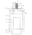
図15は実施の形態7におけるエレベーターの整風システムが適用されるエレベーターのかごの正面図である。なお、実施の形態1の部分と同一又は相当部分には同一符号が付される。当該部分の説明は省略される。
図15は実施の形態7におけるエレベーターの整風システムが適用されるエレベーターのかごの正面図である。なお、実施の形態1の部分と同一又は相当部分には同一符号が付される。当該部分の説明は省略される。
図15に示されるように、上側整風カバー11は、第1上側可動部11bと第2上側可動部11cと上側固定部11dとを備える。
例えば、第1上側可動部11bは、かご2の左部の上方に設けられる。例えば、第2上側可動部11cは、かご2の右部の上方に設けられる。例えば、上側固定部11dは、かご2の左右方向の中央部の上方に設けられる。例えば、上側固定部11dは、第1上側可動部11bと第2上側可動部11cとの間に設けられる。例えば、上側固定部11dは、上枠4に固定される。
第1上側可動部11bにおいて、かご2の中央側の縁部は、上側固定部11dの縁部に回転自在に取り付けられる。例えば、第1上側可動部11bにおいて、かご2の中央側の縁部は、回転軸によって上側固定部11dの縁部に回転自在に取り付けられる。第1上側可動部11bは、かご2の中央側の縁部を軸として回転することで、かご2の外側の縁部が上方に立ち上がり得るように設けられる。
第2上側可動部11cにおいて、かご2の中央側の縁部は、上側固定部11dの縁部に回転自在に取り付けられる。例えば、第2上側可動部11cにおいて、かご2の中央側の縁部は、回転軸によって上側固定部11dの縁部に回転自在に取り付けられる。第2上側可動部11cは、かご2の中央側の縁部を軸として回転することで、かご2の外側の縁部が上方に立ち上がり得るように設けられる。
エレベーターの平常運転時において、上側整風装置10は、かご2の上方でかご2の上部に近づけられる。具体的には、第1上側可動部11bと第2上側可動部11cとは、上側固定部11dと同じ平面上に配置された状態に維持される。
エレベーターのメンテナンス時において、上側整風装置10は、かご2の上方でかご2から遠ざけられる。具体的には、第1上側可動部11bと第2上側可動部11cとは、かご2の外側の縁部が上方に立ち上がった状態に維持される。
以上で説明した実施の形態7によれば、エレベーターの平常運転時において、上側整風装置10は、かご2の上方でかご2の上部に近づけられる。このため、昇降路の頂部の高さを低くしても、かご2が最上の位置に移動した際に上側整風装置10と昇降路の頂部との間に隙間を確保することができる。
また、エレベーターのメンテナンス時において、上側整風装置10は、かご2の上方において上側整風装置10をかご2から遠ざけられる。このため、かご2の直上において、高さ方向の作業スペースをより多く確保することができる。その結果、作業員は、かご2の直上でエレベーターのメンテナンスを容易に行うことができる。
なお、図示されないが、第1上側可動部11bと第2上側可動部11cとの回転を制限する上側整風カバー用ストッパーを設けてもよい。この場合、上側整風カバー用ストッパーにより、第1上側可動部11bと第2上側可動部11cとが上方に立ち上げられる前の状態と上方に立ち上げられた後の状態のそれぞれの状態で維持されれば、エレベーターの平常運転時とメンテナンス時とのそれぞれの時において、上側整風装置10を適切な状態に維持することができる。
また、図示されないが、第1上側可動部11bと第2上側可動部11cとをかご2の外側の縁部が上方に立ち上がる回転方向に付勢する上側整風カバー用付勢体を設けてもよい。この場合、エレベーターのメンテナンス時において、作業員が第1上側可動部11bと第2上側可動部11cとにおけるかご2の外側の縁部を上方に立ち上げる際の力を軽減することができる。
また、図示されないが、第1上側可動部11bと第2上側可動部11cとのそれぞれをさらに分割してもよい。この場合、分割された第1上側可動部11bと第2上側可動部11cとのそれぞれが回転軸によって独立して回転自在となるようにしてもよい。
実施の形態8.
図16は実施の形態8におけるエレベーターの整風システムが適用されるエレベーターのかごの正面図である。なお、実施の形態1の部分と同一又は相当部分には同一符号が付される。当該部分の説明は省略される。
図16は実施の形態8におけるエレベーターの整風システムが適用されるエレベーターのかごの正面図である。なお、実施の形態1の部分と同一又は相当部分には同一符号が付される。当該部分の説明は省略される。
図16に示されるように、上側整風装置10は、複数の上側昇降支持体11eを備える。複数の上側昇降支持体11eは、かご2の上方においてかご2の幅方向に並んで設けられる。例えば、複数の上側昇降支持体11eは、上枠4の上面に固定される。例えば、複数の上側昇降支持体11eの各々は、折畳み自在な支柱である。複数の上側昇降支持体11eは、かご2の上面との間に隙間をあけて上側整風カバー11を支持する。複数の上側昇降支持体11eは、上側整風カバー11を上下方向に移動自在に支持する。
エレベーターの平常運転時において、上側整風装置10は、かご2の上方でかご2の上部に近づけられる。具体的には、複数の上側昇降支持体11eの各々が折り畳まれることで、上側整風カバー11は、上枠4の直上に配置された状態に維持される。
エレベーターのメンテナンス時において、上側整風装置10は、かご2の上方でかご2の上部から遠ざけられる。具体的には、複数の上側昇降支持体11eの各々が折り畳みからの解放により一直線状となることで、上側整風カバー11は、上枠4との間に隙間をあけた状態に維持される。
以上で説明した実施の形態8によれば、エレベーターの平常運転時において、上側整風装置10は、かご2の上方でかご2の上部に近づけられる。このため、昇降路の頂部の高さを低くしても、かご2が最上の位置に移動した際に上側整風装置10と昇降路の頂部との間に隙間を確保することができる。
また、エレベーターのメンテナンス時において、上側整風装置10は、かご2の上方において上側整風装置10をかご2の上部から遠ざけられる。このため、かご2の直上において、高さ方向の作業スペースをより多く確保することができる。その結果、作業員は、かご2の直上でエレベーターのメンテナンスを容易に行うことができる。
なお、図示されないが、上側整風装置10の上下方向の移動を制限する上側整風装置用ストッパーを設けてもよい。この場合、上側整風装置用ストッパーにより、上側整風装置10が上方に移動される前の状態と上方に移動された後の状態のそれぞれの状態で維持されれば、エレベーターの平常運転時とメンテナンス時とのそれぞれの時において、上側整風装置10を適切な状態に維持することができる。
また、図示されないが、上側整風カバー11を上方に付勢する上側整風装置用付勢体を設けてもよい。この場合、エレベーターのメンテナンス時において、作業員が上側整風カバー11を上方に移動させる際の力を軽減することができる。
また、図示されないが、上側整風装置10を分割してもよい。この場合、分割された上側整風装置10のそれぞれが上側昇降支持体11eによって独立して上下方向に移動自在となるようにしてもよい。
実施の形態9.
図17は実施の形態9におけるエレベーターの整風システムが適用されるエレベーターのかごの側面図である。なお、実施の形態1の部分と同一又は相当部分には同一符号が付される。当該部分の説明は省略される。
図17は実施の形態9におけるエレベーターの整風システムが適用されるエレベーターのかごの側面図である。なお、実施の形態1の部分と同一又は相当部分には同一符号が付される。当該部分の説明は省略される。
図17に示されるように、下側整風カバー16は、第1下側可動部16aと第2下側可動部16bと下側固定部16cとを備える。
例えば、第1下側可動部16aは、かご2の前部の下方に設けられる。例えば、第2下側可動部16bは、かご2の後部の下方に設けられる。例えば、下側固定部16cは、かご2の前後方向の中央部の下方に設けられる。例えば、下側固定部16cは、第1下側可動部16aと第2下側可動部16bとの間に設けられる。例えば、下側固定部16cは、下枠5に固定される。
第1下側可動部16aにおいて、かご2の中央側の縁部は、下側固定部16cの縁部に回転自在に取り付けられる。例えば、第1下側可動部16aにおいて、かご2の中央側の縁部は、回転軸によって下側固定部16cの縁部に回転自在に取り付けられる。第1下側可動部16aは、かご2の中央側の縁部を軸として回転することで、かご2の外側の縁部が下方に垂れ下がり得るように設けられる。
第2下側可動部16bにおいて、かご2の中央側の縁部は、下側固定部16cの縁部に回転自在に取り付けられる。例えば、第2下側可動部16bにおいて、かご2の中央側の縁部は、回転軸によって下側固定部16cの縁部に回転自在に取り付けられる。第2下側可動部16bは、かご2の中央側の縁部を軸として回転することで、かご2の外側の縁部が下方に垂れ下がり得るように設けられる。
エレベーターの平常運転時において、下側整風装置15は、かご2の下方でかご2の下部に近づけられる。具体的には、第1下側可動部16aと第2下側可動部16bとは、下側固定部16cと同じ平面上に配置された状態に維持される。
エレベーターのメンテナンス時において、下側整風装置15は、かご2の下方でかご2から遠ざけられる。具体的には、第1下側可動部16aと第2下側可動部16bとは、かご2の外側の縁部が下方に垂れ下がった状態に維持される。
以上で説明した実施の形態9によれば、エレベーターの平常運転時において、下側整風装置15は、かご2の下方でかご2の下部に近づけられる。このため、昇降路の底部の深さを浅くしても、かご2が最下の位置に移動した際に下側整風装置15と昇降路の底部との間に隙間を確保することができる。
また、エレベーターのメンテナンス時において、下側整風装置15は、かご2の下方においてかご2から遠ざけられる。このため、かご2の直下において、高さ方向の作業スペースをより多く確保することができる。その結果、作業員は、かご2の直下でエレベーターのメンテナンスを容易に行うことができる。
なお、図示されないが、第1下側可動部16aと第2下側可動部16bとの回転を制限する下側整風カバー用ストッパーを設けてもよい。この場合、下側整風カバー用ストッパーにより、第1下側可動部16aと第2下側可動部16bとが下方に垂れ下げられる前の状態と下方に垂れ下げられた後の状態のそれぞれの状態で維持されれば、エレベーターの平常運転時とメンテナンス時とのそれぞれの時において、下側整風装置15を適切な状態に維持することができる。
また、図示されないが、第1下側可動部16aと第2下側可動部16bとを下側固定部16cから遠い方の縁部が上方に立ち上がる回転方向に付勢する下側整風カバー用付勢体を設けてもよい。この場合、エレベーターのメンテナンス時において、作業員が第1下側可動部16aと第2下側可動部16bとの下側固定部16cから遠い方の縁部を上方に立ち上げる際の力を軽減することができる。
また、図示されないが、第1下側可動部16aと第2下側可動部16bとのそれぞれをさらに分割してもよい。この場合、分割された第1下側可動部16aと第2下側可動部16bとのそれぞれが回転軸によって独立して回転自在となるようにしてもよい。
実施の形態10.
図18は実施の形態10におけるエレベーターの整風システムが適用されるエレベーターのかごの側面図である。なお、実施の形態1の部分と同一又は相当部分には同一符号が付される。当該部分の説明は省略される。
図18は実施の形態10におけるエレベーターの整風システムが適用されるエレベーターのかごの側面図である。なお、実施の形態1の部分と同一又は相当部分には同一符号が付される。当該部分の説明は省略される。
図18に示されるように、下側整風装置15は、複数の下側昇降支持体16eを備える。複数の下側昇降支持体16eは、かご2の下方においてかご2の奥行方向に並んで設けられる。例えば、複数の下側昇降支持体16eは、下枠5に固定される。例えば、複数の下側昇降支持体16eの各々は、伸縮自在な支柱である。複数の下側昇降支持体16eは、かご2の下面との間に隙間をあけて下側整風カバー16を支持する。複数の下側昇降支持体16eは、下側整風カバー16を上下方向に移動自在に支持する。
エレベーターの平常運転時において、下側整風装置15は、かご2の下方でかご2の下部に近づけられる。具体的には、複数の下側昇降支持体16eの各々が縮められることで、下側整風カバー16は、下枠5の直下に配置された状態に維持される。
エレベーターのメンテナンス時において、下側整風装置15は、かご2の下方でかご2下部から遠ざけられる。具体的には、複数の下側昇降支持体16eの各々が伸ばされることで、下側整風カバー16は、下枠5との間に隙間をあけた状態に維持される。
以上で説明した実施の形態10によれば、エレベーターの平常運転時において、下側整風装置15は、かご2の下方でかご2の下部に近づけられる。このため、昇降路の底部の深さを浅くしても、かご2が最下の位置に移動した際に下側整風装置15と昇降路の底部との間に隙間を確保することができる。
また、エレベーターのメンテナンス時において、下側整風装置15は、かご2の下方においてかご2から遠ざけられる。このため、かご2の直下において、高さ方向の作業スペースをより多く確保することができる。その結果、作業員は、かご2の直下でエレベーターのメンテナンスを容易に行うことができる。
なお、図示されないが、下側整風装置15の上下方向の移動を制限する下側整風装置用ストッパーを設けてもよい。この場合、下側整風装置用ストッパーにより、下側整風装置15が上方に移動される前の状態と上方に移動された後の状態のそれぞれの状態で維持されれば、エレベーターの平常運転時とメンテナンス時とのそれぞれの時において、下側整風装置15を適切な状態に維持することができる。
また、図示されないが、下側整風装置15を上方に付勢する下側整風装置用付勢体を設けてもよい。この場合、エレベーターのメンテナンス時において、作業員が下側整風カバー16を上方に移動させる際の力を軽減することができる。
また、図示されないが、下側整風装置15を分割してもよい。この場合、分割された下側整風装置15のそれぞれが下側昇降支持体16eによって独立して上下方向に移動自在となるようにしてもよい。
以上のように、本開示のエレベーターの整風システムは、エレベーターシステムに利用できる。
1 主ロープ、 2 かご、 3 かご枠、 4 上枠、 5 下枠、 6 縦柱、 7 ドア、 8 エプロン、 9 カウンターウェイト、 10 上側整風装置、 11 上側整風カバー、 11a 開口部、 11b 第1上側可動部、 11c 第2上側可動部、 11d 上側固定部、11e 上側昇降支持体、 12 上側可動体、 12a 上側可動板、 13 上側回転軸、 14 上側付勢体、 14a 直上付勢部、 14b 直下付勢部、 15 下側整風装置、 16 下側整風カバー、 16a 第1下側可動部、 16b 第2下側可動部、 16c 下側固定部、 16e 下側昇降支持体、 17 下側可動体、 17a 下側可動板、 18 下側回転軸、 19 下側付勢体、 19a 直上付勢部、 19b 直下付勢部、 20 上側アクチュエーター、 21 下側アクチュエーター、 22 上側接続体、 23 下側接続体、 24 上側支柱、 25 上側連結体、 26 下側支柱、 27 下側連結体
Claims (20)
- エレベーターのかごの上方または下方において前記かごから離れて設けられた整風カバーと、
前記整風カバーに隣接し、前記かごの中央側の縁部が回転自在に支持され、前記かごが上昇している際に前記かごの外側の縁部が前記かごの中央側の縁部よりも下方となるように傾斜し、前記かごが下降している際に前記かごの外側の縁部が前記かごの中央側の縁部よりも上方となるように傾斜する可動体と、
を備えたエレベーターの整風システム。 - 前記可動体は、前記かごが昇降する際の風圧で前記かごの中央側の縁部を軸として回転する請求項1に記載のエレベーターの整風システム。
- 前記かごが上昇している際に前記可動体における前記かごの外側の縁部が前記かごの中央側の縁部よりも下方となるように前記可動体を回転させ、前記かごが下降している際に前記可動体における前記かごの外側の縁部が前記かごの中央側の縁部よりも上方となるように前記可動体を回転させるアクチュエーター、
を備えた請求項1に記載のエレベーターの整風システム。 - 前記可動体は、
水平方向に並んで設けられ、前記かごの中央側の縁部が回転自在に支持され、前記かごが上昇している際に前記かごの外側の縁部が前記かごの中央側の縁部よりも下方となるように傾斜し、前記かごが下降している際に前記かごの外側の縁部が前記かごの中央側の縁部よりも上方となるように傾斜する複数の可動板、
を備えた請求項1に記載のエレベーターの整風システム。 - 前記複数の可動板を接続する接続体、
を備えた請求項4に記載のエレベーターの整風システム。 - 前記複数の可動板は、同一の回転軸で回転する請求項4または請求項5に記載のエレベーターの整風システム。
- 前記可動体は、水平投影面上において前記かごの外縁部よりも内側に配置された請求項1から請求項6のいずれか一項に記載のエレベーターの整風システム。
- エレベーターのかごの上方において前記かごから離れて設けられた整風カバーと、
前記かごの一側において前記整風カバーの縁部に隣接し、前記かごの中央側の縁部が回転自在に支持された主可動体と、
前記かごの他側において前記整風カバーの縁部に隣接し、前記かごの中央側の縁部が回転自在に支持され、前記主可動体の表面積よりも小さい表面積を有した従可動体と、
前記主可動体と前記従可動体とに対して前記かごとは反対側に設けられ、前記主可動体と前記従可動体とに連結された連結体と、
を備え、
前記主可動体は、前記かごが上昇している際の風圧で前記かごの外側の縁部が前記かごの中央側の縁部よりも下方となるように傾斜し、
前記従可動体は、前記かごが上昇している際に前記連結体を介して前記主可動体に連動することで、前記かごの外側の縁部が前記かごの中央側の縁部よりも上方となるように傾斜するエレベーターの整風システム。 - エレベーターのかごの下方において前記かごから離れて設けられた整風カバーと、
前記かごの一側において前記整風カバーの縁部に隣接し、前記かごの中央側の縁部が回転自在に支持された主可動体と、
前記かごの他側において前記整風カバーの縁部に隣接し、前記かごの中央側の縁部が回転自在に支持され、前記主可動体の表面積よりも小さい表面積を有した従可動体と、
前記主可動体と前記従可動体とに対して前記かごとは反対側に設けられ、前記主可動体と前記従可動体とに連結された連結体と、
を備え、
前記主可動体は、前記かごが下降している際の風圧で前記かごの外側の縁部が前記かごの中央側の縁部よりも上方となるように傾斜し、
前記従可動体は、前記かごが下降している際に前記連結体を介して前記主可動体に連動することで、前記かごの外側の縁部が前記かごの中央側の縁部よりも下方となるように傾斜するエレベーターの整風システム。 - 前記整風カバーは、
前記かごの上方において前記かごの中央側に固定された固定部と、
前記固定部の縁部に対して回転自在に設けられ、前記エレベーターの平常運転時において前記かごに近づけられ、前記エレベーターのメンテナンス時において前記かごの外側の縁部が上方に立ち上げられる可動部と、
を備えた請求項1から請求項9のいずれか一項に記載のエレベーターの整風システム。 - 前記整風カバーは、
前記かごの下方において前記かごの中央側に固定された固定部と、
前記固定部の縁部に対して回転自在に設けられ、前記エレベーターの平常運転時において前記かごに近づけられ、前記エレベーターのメンテナンス時において前記かごの外側の縁部が下方に垂れ下げられる可動部と、
を備えた請求項1から請求項9のいずれか一項に記載のエレベーターの整風システム。 - 前記整風カバーは、前記エレベーターの平常運転時において前記かごに近づけられ、前記エレベーターのメンテナンス時において前記かごから遠ざけられる請求項1から請求項9のいずれか一項に記載のエレベーターの整風システム。
- エレベーターのかごの上方において前記かごから離れて設けられた上側整風カバーと、
前記かごの下方において前記かごから離れて設けられた下側整風カバーと、
前記上側整風カバーに隣接し、前記かごの中央側の縁部が回転自在に支持され、前記かごが上昇している際に前記かごの外側の縁部が前記かごの中央側の縁部よりも下方となるように傾斜し、前記かごが下降している際に前記かごの外側の縁部が前記かごの中央側の縁部よりも上方となるように傾斜する上側可動体と、
前記下側整風カバーに隣接し、前記かごの中央側の縁部が回転自在に支持され、前記かごが上昇している際に前記かごの外側の縁部が前記かごの中央側の縁部よりも下方となるように傾斜し、前記かごが下降している際に前記かごの外側の縁部が前記かごの中央側の縁部よりも上方となるように傾斜する下側可動体と、
を備えたエレベーターの整風システム。 - 前記上側可動体と前記下側可動体とは、前記かごが昇降する際の風圧で前記かごの中央側の縁部を軸として回転する請求項13に記載のエレベーターの整風システム。
- 前記かごが上昇している際に前記上側可動体における前記かごの外側の縁部が前記かごの中央側の縁部よりも下方となるように前記上側可動体を回転させ、前記かごが下降している際に前記上側可動体における前記かごの外側の縁部が前記かごの中央側の縁部よりも上方となるように前記上側可動体を回転させる上側アクチュエーターと、
前記かごが上昇している際に前記下側可動体における前記かごの外側の縁部が前記かごの中央側の縁部よりも下方となるように前記下側可動体を回転させ、前記かごが下降している際に前記下側可動体における前記かごの外側の縁部が前記かごの中央側の縁部よりも上方となるように前記下側可動体を回転させる下側アクチュエーターと、
を備えた請求項13に記載のエレベーターの整風システム。 - 前記上側アクチュエーターと前記下側アクチュエーターとは、前記上側可動体の回転角度と前記下側可動体の回転角度とが一致するように動作する請求項15に記載のエレベーターの整風システム。
- 前記上側可動体は、
水平方向に並んで設けられ、前記かごの中央側の縁部が回転自在に支持され、前記かごが上昇している際に前記かごの外側の縁部が前記かごの中央側の縁部よりも下方となるように傾斜し、前記かごが下降している際に前記かごの外側の縁部が前記かごの中央側の縁部よりも上方となるように傾斜する複数の上側可動板、
を備え、
前記下側可動体は、
水平方向に並んで設けられ、前記かごの中央側の縁部が回転自在に支持され、前記かご2が上昇している際に前記かごの外側の縁部が前記かごの中央側の縁部よりも下方となるように傾斜し、前記かごが下降している際に前記かごの外側の縁部が前記かご2の中央側の縁部よりも上方となるように傾斜する複数の下側可動板、
を備えた請求項13に記載のエレベーターの整風システム。 - 前記複数の上側可動板を接続する上側接続体と、
前記複数の下側可動板を接続する下側接続体と、
を備えた請求項17に記載のエレベーターの整風システム。 - 前記複数の上側可動板は、同一の回転軸で回転し、
前記複数の下側可動板は、同一の回転軸で回転する請求項17または請求項18に記載のエレベーターの整風システム。 - 前記上側可動体と前記下側可動体とは、水平投影面上において前記かごの外縁部よりも内側に配置された請求項13から請求項19のいずれか一項に記載のエレベーターの整風システム。
Priority Applications (3)
| Application Number | Priority Date | Filing Date | Title |
|---|---|---|---|
| CN202080101970.4A CN115803276B (zh) | 2020-07-08 | 2020-07-08 | 电梯的整流系统 |
| JP2021501351A JP6930676B1 (ja) | 2020-07-08 | 2020-07-08 | エレベーターの整風システム |
| PCT/JP2020/026753 WO2022009351A1 (ja) | 2020-07-08 | 2020-07-08 | エレベーターの整風システム |
Applications Claiming Priority (1)
| Application Number | Priority Date | Filing Date | Title |
|---|---|---|---|
| PCT/JP2020/026753 WO2022009351A1 (ja) | 2020-07-08 | 2020-07-08 | エレベーターの整風システム |
Publications (1)
| Publication Number | Publication Date |
|---|---|
| WO2022009351A1 true WO2022009351A1 (ja) | 2022-01-13 |
Family
ID=77456383
Family Applications (1)
| Application Number | Title | Priority Date | Filing Date |
|---|---|---|---|
| PCT/JP2020/026753 Ceased WO2022009351A1 (ja) | 2020-07-08 | 2020-07-08 | エレベーターの整風システム |
Country Status (3)
| Country | Link |
|---|---|
| JP (1) | JP6930676B1 (ja) |
| CN (1) | CN115803276B (ja) |
| WO (1) | WO2022009351A1 (ja) |
Citations (3)
| Publication number | Priority date | Publication date | Assignee | Title |
|---|---|---|---|---|
| JPH05186171A (ja) * | 1992-01-08 | 1993-07-27 | Toshiba Corp | エレベータ |
| JPH10236740A (ja) * | 1997-02-28 | 1998-09-08 | Toshiba Corp | エレベータの制御装置 |
| JP2008056475A (ja) * | 2006-09-04 | 2008-03-13 | Toshiba Elevator Co Ltd | エレベータかごの整風装置 |
Family Cites Families (4)
| Publication number | Priority date | Publication date | Assignee | Title |
|---|---|---|---|---|
| JP5393131B2 (ja) * | 2008-12-17 | 2014-01-22 | 三菱電機株式会社 | エレベータのかご |
| JP2016056004A (ja) * | 2014-09-11 | 2016-04-21 | 株式会社日立製作所 | エレベーター装置 |
| JP6627623B2 (ja) * | 2015-10-30 | 2020-01-08 | 三菱電機株式会社 | エレベータ |
| KR102156033B1 (ko) * | 2016-12-12 | 2020-09-15 | 미쓰비시덴키 가부시키가이샤 | 엘리베이터 장치 |
-
2020
- 2020-07-08 WO PCT/JP2020/026753 patent/WO2022009351A1/ja not_active Ceased
- 2020-07-08 CN CN202080101970.4A patent/CN115803276B/zh active Active
- 2020-07-08 JP JP2021501351A patent/JP6930676B1/ja active Active
Patent Citations (3)
| Publication number | Priority date | Publication date | Assignee | Title |
|---|---|---|---|---|
| JPH05186171A (ja) * | 1992-01-08 | 1993-07-27 | Toshiba Corp | エレベータ |
| JPH10236740A (ja) * | 1997-02-28 | 1998-09-08 | Toshiba Corp | エレベータの制御装置 |
| JP2008056475A (ja) * | 2006-09-04 | 2008-03-13 | Toshiba Elevator Co Ltd | エレベータかごの整風装置 |
Also Published As
| Publication number | Publication date |
|---|---|
| JP6930676B1 (ja) | 2021-09-01 |
| CN115803276A (zh) | 2023-03-14 |
| JPWO2022009351A1 (ja) | 2022-01-13 |
| CN115803276B (zh) | 2026-02-17 |
Similar Documents
| Publication | Publication Date | Title |
|---|---|---|
| JPWO2003074409A1 (ja) | エレベータ装置 | |
| CN101139064B (zh) | 电梯轿箱的调风装置 | |
| JP6930676B1 (ja) | エレベーターの整風システム | |
| WO2019123583A1 (ja) | 機械室レスエレベータ | |
| JP2007254053A (ja) | エレベータ | |
| CN105417324B (zh) | 电梯装置 | |
| CN101786565B (zh) | 电梯装置 | |
| US20170355564A1 (en) | Elevator system | |
| JP2017171488A (ja) | エレベータ装置 | |
| JP2003312960A (ja) | エレベータ装置 | |
| JP6578248B2 (ja) | 乗りかごドア気密装置及びエレベーター装置 | |
| KR102116356B1 (ko) | 직각 관통형 엘리베이터 | |
| JP2009234752A (ja) | エレベータロープ振れ止め装置 | |
| JPWO2005105652A1 (ja) | エレベータ装置 | |
| WO2015008345A1 (ja) | エレベータ装置 | |
| WO2023286244A1 (ja) | エレベーター | |
| JP2001213580A (ja) | 加速緩和システム、エレベータシステムおよびエレベータかご室フロアシステム | |
| CN116495600B (zh) | 电梯门的地坎 | |
| JP6742946B2 (ja) | ガバナ装置及びエレベーター | |
| JP2004002045A (ja) | エレベーター装置 | |
| JP7429088B2 (ja) | エレベータ及びそのピット作業補助装置 | |
| JP2004002045A5 (ja) | ||
| JP6326361B2 (ja) | エレベーター装置 | |
| JP2005298133A (ja) | 免震建物用エレベーター装置 | |
| JP7515309B2 (ja) | シースルーエレベーター |
Legal Events
| Date | Code | Title | Description |
|---|---|---|---|
| ENP | Entry into the national phase |
Ref document number: 2021501351 Country of ref document: JP Kind code of ref document: A |
|
| 121 | Ep: the epo has been informed by wipo that ep was designated in this application |
Ref document number: 20943974 Country of ref document: EP Kind code of ref document: A1 |
|
| NENP | Non-entry into the national phase |
Ref country code: DE |
|
| 122 | Ep: pct application non-entry in european phase |
Ref document number: 20943974 Country of ref document: EP Kind code of ref document: A1 |