WO2021256178A1 - 成形コイル、ステータ及び回転電機 - Google Patents
成形コイル、ステータ及び回転電機 Download PDFInfo
- Publication number
- WO2021256178A1 WO2021256178A1 PCT/JP2021/019499 JP2021019499W WO2021256178A1 WO 2021256178 A1 WO2021256178 A1 WO 2021256178A1 JP 2021019499 W JP2021019499 W JP 2021019499W WO 2021256178 A1 WO2021256178 A1 WO 2021256178A1
- Authority
- WO
- WIPO (PCT)
- Prior art keywords
- coil
- winding
- stator
- terminal
- terminal portion
- Prior art date
- Legal status (The legal status is an assumption and is not a legal conclusion. Google has not performed a legal analysis and makes no representation as to the accuracy of the status listed.)
- Ceased
Links
Images


Classifications
-
- H—ELECTRICITY
- H02—GENERATION; CONVERSION OR DISTRIBUTION OF ELECTRIC POWER
- H02K—DYNAMO-ELECTRIC MACHINES
- H02K3/00—Details of windings
- H02K3/04—Windings characterised by the conductor shape, form or construction, e.g. with bar conductors
- H02K3/18—Windings for salient poles
-
- H—ELECTRICITY
- H01—ELECTRIC ELEMENTS
- H01F—MAGNETS; INDUCTANCES; TRANSFORMERS; SELECTION OF MATERIALS FOR THEIR MAGNETIC PROPERTIES
- H01F5/00—Coils
- H01F5/04—Arrangements of electric connections to coils, e.g. leads
-
- H—ELECTRICITY
- H02—GENERATION; CONVERSION OR DISTRIBUTION OF ELECTRIC POWER
- H02K—DYNAMO-ELECTRIC MACHINES
- H02K1/00—Details of the magnetic circuit
- H02K1/06—Details of the magnetic circuit characterised by the shape, form or construction
- H02K1/12—Stationary parts of the magnetic circuit
- H02K1/16—Stator cores with slots for windings
-
- H—ELECTRICITY
- H02—GENERATION; CONVERSION OR DISTRIBUTION OF ELECTRIC POWER
- H02K—DYNAMO-ELECTRIC MACHINES
- H02K3/00—Details of windings
- H02K3/04—Windings characterised by the conductor shape, form or construction, e.g. with bar conductors
- H02K3/12—Windings characterised by the conductor shape, form or construction, e.g. with bar conductors arranged in slots
-
- H—ELECTRICITY
- H02—GENERATION; CONVERSION OR DISTRIBUTION OF ELECTRIC POWER
- H02K—DYNAMO-ELECTRIC MACHINES
- H02K3/00—Details of windings
- H02K3/04—Windings characterised by the conductor shape, form or construction, e.g. with bar conductors
- H02K3/28—Layout of windings or of connections between windings
-
- Y—GENERAL TAGGING OF NEW TECHNOLOGICAL DEVELOPMENTS; GENERAL TAGGING OF CROSS-SECTIONAL TECHNOLOGIES SPANNING OVER SEVERAL SECTIONS OF THE IPC; TECHNICAL SUBJECTS COVERED BY FORMER USPC CROSS-REFERENCE ART COLLECTIONS [XRACs] AND DIGESTS
- Y02—TECHNOLOGIES OR APPLICATIONS FOR MITIGATION OR ADAPTATION AGAINST CLIMATE CHANGE
- Y02T—CLIMATE CHANGE MITIGATION TECHNOLOGIES RELATED TO TRANSPORTATION
- Y02T10/00—Road transport of goods or passengers
- Y02T10/60—Other road transportation technologies with climate change mitigation effect
- Y02T10/64—Electric machine technologies in electromobility
Definitions
- the present disclosure relates to a rotary electric machine including an electric machine, a stator used in the rotary electric machine, and a molded coil used as a winding coil of the stator.
- Electric machines As one of the rotary electric machines, an electric machine that converts electric energy into mechanical energy is known.
- Motors are used in various products such as household equipment or industrial equipment.
- electric motors are widely used in automobiles, robots, and the like, as well as home appliances such as vacuum cleaners.
- Patent Document 1 discloses an electric motor using a molded coil molded to fit the slot shape of a stator.
- the winding coil is arranged in the slot of the stator.
- a plurality of winding coils arranged in the slots of the stator are electrically connected to each other by being connected.
- the round wire coil configured by the round wire can freely route the round wire drawn from the winding portion, in the stator using the round wire coil as the winding coil, a plurality of round wires arranged in the slot.
- the round wire coils can be easily connected to each other.
- the molded coil is composed of a plate-shaped conductor having high rigidity. Therefore, in the stator using the molded coil as the winding coil, it is not possible to easily connect the plurality of molded coils arranged in the slots to each other as compared with the case of using the round wire coil.
- a winding portion in which plate frame-shaped conductors are laminated a first terminal portion protruding from the first turn (winding start) portion of the winding portion, and a final turn (winding) of the winding portion.
- Those having a second terminal portion protruding from the end) portion are known.
- the positions of the first terminal portion and the second terminal portion in each molded coil are different in the radial direction of the stator. That is, the positions of the first terminal portion and the second terminal portion in each molded coil do not exist at equidistant positions from the center of the stator. That is, the first terminal portion and the second terminal portion are not located on the same circumference.
- a connecting member such as a bus bar.
- a bus bar is bridged between two adjacent molded coils, and the first terminal portion of one of the two molded coils and one end of the bus bar are joined to each other, and the two molded coils are joined. The second terminal portion of the other molded coil and the other end portion of the bus bar are joined.
- the present disclosure provides a molded coil, a stator using the molded coil, and a rotary electric machine using the stator, which can easily connect two molded coils without using a connecting member such as a bus bar. The purpose.
- one aspect of the molded coil according to the present disclosure is one of two molded coils arranged adjacent to each other, from the first turn to the nth turn (n is).
- a first having a winding portion in which conductors are laminated with (2 or more integers) and a lead portion extending from the first turn of the winding portion in a direction orthogonal to the stacking direction of the conductors in the winding portion.
- the first terminal portion includes a terminal portion and a second terminal portion having a lead portion extending in a direction orthogonal to the stacking direction of the conductor in the winding portion from the nth turn portion of the winding portion.
- a first engaging portion that engages with a second engaging portion formed at the tip of the terminal portion of the other molded coil of the two molded coils is formed at the tip of the terminal portion.
- one aspect of the stator according to the present disclosure includes a core having a plurality of teeth and a plurality of molded coils each wound around the plurality of teeth, and the plurality of molded coils are the first molded coil.
- the n 1 turns from the first turn (n 1 is an integer of 2 or more) first conductor
- a lead portion extending in a direction orthogonal to the stacking direction of the first conductor in the first winding portion from the first turn portion of the first winding portion and the first winding portion in which the first winding portion is laminated.
- the second having a first terminal portion, the lead portion extending in a direction perpendicular to the stacking direction of the first conductor from said portion of said n 1 turn of the first winding part of the first winding portion having has a terminal portion, said second forming coil has a second winding section first n 2 turns from the first turn (n 2 is an integer greater than or equal to 2) of the second conductor in stacked, the second A third terminal portion having a lead portion extending in a direction orthogonal to the stacking direction of the second conductor in the second winding portion from the first turn portion of the winding portion, and the second winding portion.
- a first engaging portion is formed at the tip portion, and a second engaging portion that engages with the first engaging portion is formed at the tip portion of the third terminal portion.
- the 1-terminal portion and the third terminal portion are connected by joining the first engaging portion and the second engaging portion.
- one aspect of the rotary electric machine according to the present disclosure includes the above-mentioned stator and a rotor that rotates by the magnetic force of the stator.
- FIG. 1 It is sectional drawing of the electric motor which concerns on embodiment. It is a perspective view of the stator in the electric motor which concerns on embodiment. It is an enlarged view of two adjacent molded coils in the stator of the motor which concerns on embodiment. It is a top view of two adjacent molded coils in the stator of the motor which concerns on embodiment. It is a figure which shows the state at the time of connecting two adjacent molded coils in the stator of the electric motor which concerns on embodiment. It is an enlarged view of two adjacent molded coils in the stator which concerns on modification 1. FIG. It is a top view of two adjacent molded coils in the stator which concerns on modification 1. FIG. It is a figure which shows the state at the time of connecting two adjacent molding coils in the stator which concerns on modification 1.
- FIG. It is an enlarged view of two adjacent molded coils in the stator which concerns on modification 2.
- FIG. It is a top view of two adjacent molded coils in the stator which concerns on modification 2.
- FIG. It is a figure which shows the state at the time of connecting two adjacent molding coils in the stator which concerns on modification 2.
- FIG. It is a figure which shows the structure of two adjacent forming coils in the stator which concerns on modification 3 and the state when the two forming coils are connected.
- FIG. 10 It is another figure which shows the state when the two forming coils shown in FIG. 10 are connected.
- FIG. 10 It is another figure which shows the state when the two forming coils shown in FIG. 10 are connected. It is a figure which shows the other structure of the molded coil which concerns on modification 4. It is a perspective view of the stator which concerns on modification 5. FIG. It is an enlarged view of two adjacent molded coils in the stator which concerns on modification 5. FIG.
- the radial direction of the stator 10 and the rotor 20 is the "radial direction”
- the rotation direction of the rotor 20 is the "circumferential direction”. That is, the direction extending from the axis C around the axis C of the rotating shaft 23 is the "diameter direction", and the direction rotating around the axis C around the axis C of the rotating shaft 23 is the "circumferential direction”. .. Therefore, the "diametrical direction” is a direction orthogonal to the direction of the axis C of the rotating shaft 23.
- the terms “upper” and “lower” do not necessarily refer to the upward direction (vertically upward) and the downward direction (vertically downward) in absolute spatial recognition.
- FIG. 1 is a cross-sectional view of the electric motor 1 according to the embodiment.
- FIG. 2 is a perspective view of the stator 10 in the motor 1. Note that FIG. 1 shows a cross section when cut in a plane orthogonal to the direction of the axis C of the rotating shaft 23 of the rotor 20.
- the motor 1 includes a stator 10 and a rotor 20.
- the stator 10 and the rotor 20 are arranged so as to face each other.
- the electric motor 1 is an inner rotor type motor in which the rotor 20 is arranged inside the stator 10.
- the motor 1 also has parts such as a bearing that supports the motor case and the rotating shaft 23, but for convenience, the illustration and description of the parts will be omitted.
- the stator 10 (stator) is arranged between the stator and the rotor 20 so as to face the rotor 20 via an air gap. There is a small air gap between the surface of the rotor 20 and the surface of the stator 10. In the present embodiment, the stator 10 is arranged so as to surround the rotor core 21 of the rotor 20.
- the stator 10 generates a magnetic force acting on the rotor 20.
- the stator 10 is configured to generate a magnetic flux on the air gap surface of the rotor 20 with the rotor core 21.
- the stator 10 is configured such that N poles and S poles are alternately and repeatedly generated in the circumferential direction on the surface facing the air gap with the rotor core 21.
- the stator 10 has a molded coil 100 and a stator core 200.
- the molded coil 100 is a stator coil provided on the stator 10 as a winding coil.
- the forming coil 100 is an armature winding of the stator 10, and is wound around the stator core 200. Specifically, the forming coil 100 is wound around each of the plurality of teeth 210 of the stator 10. Therefore, a plurality of molded coils 100 are used for the stator 10.
- the plurality of molded coils 100 are each wound around a plurality of teeth 210.
- the plurality of molded coils 100 are arranged at equal intervals along the circumferential direction so as to surround the rotor 20. Each molded coil 100 is housed in the slot 230 of the stator 10.
- the forming coil 100 may be wound around the teeth 210 via an insulating member (not shown) such as an insulator or insulating paper. In this case, the forming coil 100 is wound around an insulator mounted on the teeth 210, for example.
- the molded coil 100 is configured by laminating plate-shaped conductors, unlike a round wire coil using a round wire.
- the molded coil 100 has a higher space factor than the round wire coil.
- the space factor of the molded coil 100 is 90% or more.
- the forming coil 100 is formed, for example, by preparing a plurality of rectangular plates having different lengths, widths, and thicknesses, pressing the plates, and joining them by cold pressure welding, welding, or other methods. be able to.
- the plate material for example, a metal plate made of a low resistance metal material such as copper or aluminum can be used.
- the molded coil 100 may be formed by so-called casting, in which a metal material such as copper is melted and poured into a mold. Further, it may be formed by bending a plate-shaped conducting wire having a width or a thickness different in the middle at a predetermined position. Further, a plate-shaped conductor having a constant width and thickness may be rolled at a predetermined portion, the width or thickness may be changed in the middle, and then the conductor may be spirally wound. That is, the forming coil 100 can be formed by adding another process other than winding the conductor, or by using a method different from simply winding the lead wire.
- the shape of the forming coil 100 and the joining structure between the forming coils 100 will be described later.
- the stator core 200 is an iron core that is the core of the stator 10.
- the stator core 200 is composed of a plurality of teeth 210 and an annular yoke 220.
- Each of the plurality of teeth 210 projects toward the axis C of the rotating shaft 23 of the rotor 20. Specifically, the plurality of teeth 210 are provided radially in a direction (diametrical direction) orthogonal to the axis C of the rotating shaft 23.
- a slot 230 for arranging the forming coil 100 is formed between two adjacent teeth 210. That is, the slot 230 of the stator 10 corresponds between two adjacent teeth 210.
- the plurality of teeth 210 are arranged at equal intervals along the circumferential direction while forming slots 230 between two adjacent teeth 210.
- the number of slots of the stator 10 is 12. Therefore, 12 molding coils 100 are used.
- each tooth 210 extends radially inward from the annular yoke 220. That is, the yoke 220 is a back yoke formed on the outside of each tooth 210. Each tooth 210 is fitted and fixed to the yoke 220.
- Each of the teeth 210 and the yoke 220 is a laminated body formed by laminating a plurality of electromagnetic steel sheets.
- Each of the plurality of electromagnetic steel sheets is, for example, a punched steel sheet formed into a predetermined shape.
- the teeth 210 and the yoke 220 are separate bodies, they may be integrated as one stator core 200. Even when the teeth 210 and the yoke 220 are integrated, the stator core 200 is a laminated body formed by laminating a plurality of electromagnetic steel sheets.
- the teeth 210 and the yoke 220 are not limited to a laminated body of a plurality of electrical steel sheets, whether they are separate bodies or integrally, and may be a bulk body made of a magnetic material. good.
- the plurality of teeth 210 are magnetic pole teeth, and a magnetic force is generated by energization of the forming coil 100.
- the plurality of forming coils 100 in the stator 10 are electrically connected as a three-phase winding so that the rotor 20 rotates as a three-phase synchronous motor.
- the plurality of molded coils 100 are composed of unit coils of each of the three phases of U phase, V phase and W phase, which are electrically different in phase by 120 degrees from each other. That is, the molded coil 100 mounted on each tooth 210 is energized and driven by a three-phase alternating current that is energized in units of U phase, V phase, and W phase. As a result, the main magnetic flux of the stator 10 is generated in each tooth 210.
- the 12 forming coils 100 have four U-phase coils U1 to U4 and four V-phase coils V1 to V4 according to the phase of the current flowing through each forming coil 100. It is divided into four W-phase coils W1 to W4 and arranged in a predetermined slot 230.
- the four U-phase coils U1 to U4 are connected in series.
- the four V-phase coils V1 to V4 are connected in series.
- the four W-phase coils W1 to W4 are also connected in series.
- the rotor 20 (rotor) is rotated by the magnetic force of the stator 10.
- the rotor 20 also generates a magnetic force.
- the rotor 20 has a configuration in which a plurality of N poles and S poles that generate magnetic flux in the circumferential direction are alternately and repeatedly present.
- the rotor 20 generates a magnetic force acting on the stator 10.
- the direction of the magnetic flux generated from the rotor 20 is a direction orthogonal to the direction of the axis C of the rotating shaft 23 (direction of the axis). That is, the direction of the magnetic flux generated by the rotor 20 is the radial direction (diameter direction).
- the rotor 20 has a rotor core 21, a plurality of permanent magnets 22, and a rotating shaft 23.
- the rotor 20 rotates about the axis C of the rotating shaft 23 as the center of rotation. That is, the rotation shaft 23 becomes the central axis when the rotor 20 rotates.
- the rotor 20 is a permanent magnet embedded rotor (IPM (Interior Permanent Magnet) rotor) in which the permanent magnet 22 is embedded in the rotor core 21. Therefore, the electric motor 1 in the present embodiment is an IPM motor.
- IPM Interior Permanent Magnet
- the rotor core 21 is an iron core that is the core of the rotor 20.
- the rotor core 21 is a laminated body in which a plurality of electrical steel sheets are laminated in the direction of the axial center C of the rotating shaft 23 (axial center direction).
- Each of the plurality of electromagnetic steel sheets is, for example, a punched steel sheet formed into a predetermined shape.
- a plurality of electrical steel sheets are fixed to each other by, for example, caulking.
- the rotor core 21 is not limited to a laminated body of a plurality of electromagnetic steel sheets, but may be a bulk body made of a magnetic material.
- the permanent magnet 22 is arranged in the magnet insertion hole provided in the rotor core 21.
- the rotor core 21 is provided with 10 magnet insertion holes.
- a plate-shaped permanent magnet 22 is inserted into each magnet insertion hole.
- the permanent magnet 22 is a sintered magnet.
- the permanent magnet 22 may be a bond magnet.
- the rotating shaft 23 is a long shaft, for example, a metal rod.
- the rotating shaft 23 is fixed to the rotor core 21. Specifically, the rotating shaft 23 is inserted into a through hole provided in the center of the rotor core 21 and fixed to the rotor core 21 so as to extend on both sides of the rotor core 21 in the direction of the axis C.
- the rotary shaft 23 is fixed to the rotor core 21 by, for example, press-fitting or shrink-fitting into the through hole of the rotor core 21.
- one of the portions of the rotating shaft 23 protruding from the rotor core 21 functions as an output shaft.
- a load such as a rotating fan is attached to the rotating shaft 23.
- the rotary shaft 23 is rotatably supported by a bearing such as a bearing.
- a field current flows through the forming coil 100 and a magnetic field is generated in the stator 10.
- a magnetic flux from the stator 10 to the rotor 20 is generated.
- a magnetic flux is generated from each of the teeth 210 of the stator core 200 of the stator 10 toward the rotor 20.
- a magnetic flux passing through the stator 10 is generated by the permanent magnets 22 arranged in the rotor core 21.
- the magnetic force generated by the interaction between the magnetic flux generated by the stator 10 and the magnetic flux generated by the permanent magnet 22 of the rotor 20 becomes the torque for rotating the rotor 20, and the rotor 20 rotates.
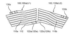
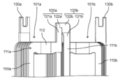
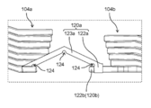
- FIG. 3A is an enlarged view of two adjacent molded coils 100 in the stator 10 of the motor 1 according to the embodiment.
- FIG. 3B is a top view of two adjacent molded coils 100 in the stator 10.
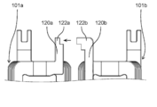
- FIG. 4 is a diagram showing a state when two adjacent forming coils 100 in the same stator 10 are connected.
- the four U-phase coils U1 to U4 shown in FIGS. 1 and 2 as the forming coil 100 are connected in series.
- Two molded coils 100 of the U-phase coil U1 and the U-phase coil U2 are arranged next to each other.
- two molded coils 100 of the U-phase coil U3 and the U-phase coil U4 are arranged next to each other.
- two molded coils 100 of the V-phase coil V1 and the V-phase coil V2 are arranged next to each other.
- Two molded coils 100 of the V-phase coil V3 and the V-phase coil V4 are arranged next to each other.
- Two molded coils 100, a W-phase coil W1 and a W-phase coil W2 are arranged next to each other.
- Two molded coils 100 of the W-phase coil W3 and the W-phase coil W4 are arranged next to each other.
- the first forming coil 100a and the second forming coil are used. It is directly connected to 100b without a connecting member such as a bus bar.
- the configuration of the molded coil 100 will be described in detail, and the structure of the joint portion of the two molded coils 100 arranged adjacent to each other will be described in detail.
- the molded coil 100 which is the U-phase coil U1 is designated as the first molded coil 100a
- the molded coil 100 which is the U-phase coil U2 is the first.
- a case where the U-phase coil U1 and the U-phase coil U2 are joined as the two forming coil 100b will be described as an example.
- the first molded coil 100a and the second molded coil 100b are composed of a plate-shaped conductor coated with an insulating coating.
- the plate-shaped first conductor constituting the first forming coil 100a and the plate-shaped second conductor constituting the second forming coil 100b both have a quadrangular cross-sectional shape and are made of copper.
- the first forming coil 100a includes a first winding portion 110a, a first terminal portion 120a and a second terminal portion protruding upward from the first winding portion 110a. It has 130a and.
- First winding unit 110a the winding start and the first turn, the winding end first n 1 turn (n 1 is an integer of 2 or more)
- n 1 is an integer of 2 or more
- the first winding portion 110a has laminated conductors constituting the coil of n 1 turn.
- the first winding portion 110a is laminated so that a flat plate-shaped conductor is spirally wound in the thickness direction.
- the shape of the first winding portion 110a is substantially a rectangular frame shape. That is, the first winding portion 110a made of n turns of a flat conductor of the first turn to the n 1 turn, substantially rectangular annular with four sides as viewed from the radial direction of the stator 10 Is formed in.
- the first winding portion 110a is arranged so that the portion of the first turn is located at the inner portion of the stator 10 and the portion of the nth turn is located at the outer portion of the stator 10. That is, the first winding portion 110a is laminated in this order from the portion of the first turn to the portion of the nth turn 1 from the axial center C of the rotating shaft 23 toward the outer side in the radial direction.
- the first winding portion 110a is housed in the slot 230.
- the outer shape of the first winding portion 110a has a shape suitable for the slot 230.
- the interface between turns is insulated. Accordingly, the current supplied to the first winding unit 110a will flow spirally from the first turn or from the n 1 turn to first turn to the n 1 turn.
- the first terminal portion 120a and the second terminal portion 130a function as a wiring portion for electrically connecting the first forming coil 100a to other forming coils 100 other than the first forming coil 100a.
- the first terminal portion 120a is connected to the second forming coil 100b, which is the U-phase coil U2
- the second terminal portion 130a is connected to the U-phase coil U3 or the U-phase coil U4.
- the first terminal portion 120a is a portion where the conductor extends from the first turn of the first winding portion 110a.
- the first forming coil 100a has an extending portion 112 extending toward the second forming coil 100b as a part of the first winding portion 110a of the portion of the first turn, and the first terminal portion 120a has an extending portion 112. , It extends from the extension portion 112.
- the extending portion 112 extends toward the coil end 111b of the second winding portion 110b in the second forming coil 100b as a part of the coil end 111a of the first winding portion 110a.
- the first terminal portion 120a projects upward from the end portion of the extending portion 112 on the second forming coil 100b side.
- the first terminal portion 120a protruding from the first winding portion 110a has a lead portion 121a and a first engaging portion 122a.
- the lead portion 121a is a portion extending from the portion of the first turn of the first winding portion 110a in the direction orthogonal to the stacking direction of the conductors in the first winding portion 110a. In the present embodiment, the lead portion 121a extends linearly upward from the end portion of the extending portion 112 on the second forming coil 100b side.
- the first engaging portion 122a has a shape that fits with the second engaging portion 122b of the second forming coil 100b. As shown in FIGS. 3A, 3B and 4, the first engaging portion 122a has a recess that fits into the second engaging portion 122b. Further, the first engaging portion 122a is formed at the tip end portion of the first terminal portion 120a. Specifically, the first engaging portion 122a is formed at the tip end portion of the lead portion 121a.
- the second terminal portion 130a is a portion where the conductor extends from the first winding portion 110a, similarly to the first terminal portion 120a.
- the second terminal portion 130a is a portion where the conductive from the n 1 turn of the first winding portion 110a extends.
- the second terminal portion 130a has a lead portion extending in a direction perpendicular to the stacking direction of the conductor at the portion of the n 1 turn of the first winding unit 110a first winding unit 110a.
- the second terminal portion 130a extends in the same direction as the first terminal portion 120a.
- the second forming coil 100b As shown in FIGS. 2, 3A, and 3B, the second forming coil 100b has a second winding portion 110b, a third terminal portion 120b and a fourth terminal protruding upward from the second winding portion 110b. It has a portion 130b.
- Second winding unit 110b a winding start first and turn the winding end when the n 2 turns (n 2 is an integer of 2 or more) that, similarly to the first winding portion 110a of the first molded coil 100a has a structure in which the conductor is laminated from the first turn to the n 2 turns. That is, the second coil portion 110b has a stacked conductors constituting the n 2 turns of the coil. Similar to the first winding portion 110a, the second winding portion 110b is laminated so that a flat plate-shaped conductor is spirally wound in the thickness direction.
- the shape of the second winding portion 110b is substantially a rectangular frame shape. That is, the second coil portion 110b made of n turns of a flat conductor of the first turn to the n 2 turns, substantially rectangular annular with four sides as viewed from the radial direction of the stator 10 Is formed in.
- the frame-shaped size of the second winding portion 110b is the same as the frame-shaped size of the first winding portion 110a.
- the frame-shaped size of the second winding portion 110b and the frame-shaped size of the first winding portion 110a may be different.
- the number of turns of the second winding portion 110b and the number of turns of the first winding portion 110a may be different.
- the second winding portion 110b, the part of the first turn in the inner portion of the stator 10, part of the n 2 turns are arranged so as to be located on the outside portion of the stator 10. That is, the second winding portion 110b is laminated in this order from the portion of the first turn to the portion of the nth turn 2 from the axial center C of the rotating shaft 23 toward the outer side in the radial direction.
- the second winding portion 110b is housed in the slot 230.
- the outer shape of the second winding portion 110b has a shape suitable for the slot 230.
- the interface between turns is insulated. Accordingly, the current supplied to the second winding unit 110b will flow spirally from the first turn or from the n 2 turns to the first turn to the n 2 turns.
- the second molded coil 100b unlike the first molded coil 100a, does not have the extending portion 112 formed in the first winding portion 110a in the second winding portion 110b.
- the second winding portion 110b has the same shape and size as the first winding portion 110a except that the extending portion 112 is not formed.
- the third terminal portion 120b and the fourth terminal portion 130b function as a wiring portion for electrically connecting the second molding coil 100b to other molding coils 100 other than the second molding coil 100b.
- the third terminal portion 120b is connected to the first forming coil 100a which is the U-phase coil U1
- the fourth terminal portion 130b is connected to the U-phase coil U3 or the U-phase coil U4.
- the third terminal portion 120b is a portion where the conductor extends from the first turn of the second winding portion 110b.
- the third terminal portion 120b protrudes from the coil end 111b of the second winding portion 110b.
- the third terminal portion 120b has a lead portion 121b and a second engaging portion 122b.
- the lead portion 121b is a portion extending from the portion of the first turn of the second winding portion 110b in the direction orthogonal to the stacking direction of the conductors in the second winding portion 110b. In the present embodiment, the lead portion 121b extends linearly upward from the coil end 111b of the second winding portion 110b.
- the second engaging portion 122b engages with the first engaging portion 122a of the first forming coil 100a.
- the second engaging portion 122b has a shape that fits with the first engaging portion 122a of the first forming coil 100a. That is, the first engaging portion 122a of the first molded coil 100a and the second engaging portion 122b of the second molded coil 100b have a shape that fits each other.
- the second engaging portion 122b since the first engaging portion 122a of the first forming coil 100a has a concave portion, the second engaging portion 122b has a convex portion that fits with the concave portion. ..
- the first terminal portion 120a of the first molded coil 100a and the third terminal portion 120b of the second molded coil 100b are connected by joining the first engaging portion 122a and the second engaging portion 122b. ..
- the first engaging portion 122a and the second engaging portion 122 are joined by welding, soldering, caulking, fusing, or the like.
- the joined first engaging portion 122a and the second engaging portion 122b are electrically and mechanically connected. Therefore, at least the joint portion between the first engaging portion 122a and the second engaging portion 122b has the insulating film covering the conductor removed.
- the second engaging portion 122b is formed at the tip end portion of the third terminal portion 120b. Specifically, the second engaging portion 122b is formed at the tip end portion of the lead portion 121b.
- the fourth terminal portion 130b similar to the third terminal portion 120b, but the conductor from the second winding portion 110b is a portion that extends, the fourth terminal part 130b includes a first n 2 of the second winding portion 110b This is the part where the conductor extends from the turn.
- the fourth terminal portion 130b includes a lead portion extending in a direction perpendicular to the portion of the n 2 turns of the second winding portion 110b and the stacking direction of the conductors in the second winding unit 110b.
- the fourth terminal portion 130b extends in the same direction as the third terminal portion 120b.
- the first forming coil 100a and the second forming coil 100b configured in this way are the first turn of the first winding portion 110a of the first forming coil 100a and the second winding portion 110b of the second forming coil 100b. It is arranged so that it is located on the same side as the first turn.
- the first turn of the first winding portion 110a and the first turn of the second winding portion 110b are the stators 10. It is arranged so as to be located in the inner part of.
- the first terminal portion 120a is provided so as to be located on the inner portion of the stator 10 and on the side of the second forming coil 100b.
- the second terminal portion 130a is provided so as to be located on the outer side of the stator 10 on the side opposite to the inside of the stator 10 and on the side opposite to the second molded coil 100b side.
- the third terminal portion 120b is provided so as to be located on the inner portion of the stator 10 and on the side of the first molded coil 100a.
- the fourth terminal portion 130b is provided so as to be located on the outer side portion of the stator 10 and on the side opposite to the first forming coil 100a side.
- first terminal portion 120a of the first molding coil 100a and the third terminal portion 120b of the second molding coil 100b are located inside the stator 10.
- the second terminal portion 130a of the first molding coil 100a and the fourth terminal portion 130b of the second molding coil 100b are located on the outer side portion of the stator 10.
- the first terminal portion 120a of the first molding coil 100a and the third terminal portion 120b of the second molding coil 100b are provided close to each other so as to be close to each other.
- the second terminal portion 130a of the first molding coil 100a and the fourth terminal portion 130b of the second molding coil 100b are provided so as to be separated from each other.
- the first terminal portion 120a and the second terminal portion 130a are substantially diagonal to each other in the first forming coil 100a. positioned. Further, in the second molded coil 100b, the third terminal portion 120b and the fourth terminal portion 130b are substantially diagonally opposite to the diagonal direction of the first terminal portion 120a and the second terminal portion 130a. Is located in.
- the first engaging portion 122a provided on the first terminal portion 120a of the first forming coil 100a and the second terminal portion 120b provided on the third terminal portion 120b of the second forming coil 100b. It is located at the same height as the engaging portion 122b.
- the first engaging portion 122a and the second engaging portion 122b are located at the same height with respect to the upper surface of the coil end 111a or 111b.
- the concave portion of the first engaging portion 122a and the convex portion of the second engaging portion 122b are located at the same height with respect to the upper surface of the coil end 111a or 111b.
- the tip portion of the first terminal portion 120a of the first molding coil 100a is attached to the tip portion of the third terminal portion 120b of the second molding coil 100b.
- a first engaging portion 122a that engages with the formed second engaging portion 122b is formed.
- the forming coil 100 is one of the two forming coils 100 arranged adjacent to each other, and is formed from the first turn to the nth turn (n is an integer of 2 or more).
- a winding portion in which conductors are laminated a first terminal portion 120a having a lead portion 121a extending in a direction orthogonal to the stacking direction of the conductors in the winding portion from the first turn of the winding portion, and a winding portion.
- a second terminal portion 130a having a lead portion extending in a direction orthogonal to the stacking direction of the conductors in the winding portion from the portion of the nth turn is provided, and two moldings are formed on the tip portion of the first terminal portion 120a.
- a first engaging portion 122a that engages with a second engaging portion 122b formed at the tip of a third terminal portion 120b of the other molded coil 100 of the coil 100 is formed.
- the first terminal portion 120a of the first molded coil 100a and the third terminal portion 120b of the second molded coil 100b are connected by joining the first engaging portion 122a and the second engaging portion 122b. ing.
- the two forming coils 100 of the first forming coil 100a and the second forming coil 100b can be directly connected and connected. This makes it possible to easily connect the two forming coils 100 of the first forming coil 100a and the second forming coil 100b without using a connecting member such as a bus bar.
- the first engaging portion 122a of the first forming coil 100a has a recess, and the second engaging portion 122b of the second forming coil 100b. Has a convex portion, and the first engaging portion 122a is engaged with the second engaging portion 122b by fitting the convex portion and the concave portion.
- the first engaging portion 122a and the second engaging portion 122b can be fitted by the concave-convex structure. Therefore, the first engaging portion 122a and the second engaging portion 122b can be easily engaged and joined. Therefore, the connection between the first forming coil 100a and the second forming coil 100b can be performed more easily.
- the first forming coil 100a has an extending portion 112 extending toward the second forming coil 100b as a part of the first winding portion 110a of the portion of the first turn.
- the first terminal portion 120a on which the first engaging portion 122a is formed extends from the tip end portion of the extending portion 112.
- the extending portion 112 is formed as a part of the coil end 111a of the first winding portion 110a.
- the first terminal portion 120a is provided via the coil end 111a, the first terminal portion 120a can be easily brought close to the third terminal portion 120b of the second molded coil 100b. Moreover, by forming the extending portion 112 using the coil end 111a, it is easy to make the first terminal portion 120a into the third terminal portion 120b without having to bend the first terminal portion 120a to form a complicated shape. Can be approached to.
- a connecting member such as a bus bar is used for the first terminal portion 120a of the first forming coil 100a which is the U-phase coil U1 and the third terminal portion 120b of the second forming coil 100b which is the U-phase coil U2. Directly connected without.
- the second terminal portion 130a of the first molding coil 100a which is the U-phase coil U1
- is the second terminal portion 130a of the molding coil 100 which is the U-phase coil U3, or the fourth terminal of the molding coil 100, which is the U-phase coil U4. It is connected to the portion 130b by using a bus bar or a lead wire.
- the fourth terminal portion 130b of the second molded coil 100b which is the U-phase coil U2
- the four molded coils 100 of the V-phase coils V1 to V4 and the four molded coils 100 of the W-phase coils W1 to W4 are connected in the same manner as the four molded coils 100 of the U-phase coils U1 to U4, respectively. It can be performed.
- the first forming coil 100a may be used.
- the first terminal portion 120a and the second terminal portion 130a are arranged diagonally to keep the first terminal portion 120a and the second terminal portion 130a away from each other.
- the third terminal portion 120b and the fourth terminal portion 130b are arranged diagonally in order to secure the dielectric strength between the terminals, and the third terminal portion 120b and the fourth terminal portion are arranged. It is far from 130b.
- the terminal portion of the molded coil 100 of the V-phase coil V2 is the second terminal portion of the first molded coil 100a. It will approach 130a.
- the second terminal portion 130a of the first forming coil 100a of the U-phase coil U1 is the circumferential end edge of the first winding portion 110a (the end edge of the V-phase coil V2 on the forming coil 100 side). Is retreating from. As a result, the end edge (the molded coil 100 side of the V-phase coil V2) opposite to the second molded coil 100b side in the second terminal portion 130a and the first winding portion 110a of the first molded coil 100a of the U-phase coil U1.
- the distance from the end edge of W3 on the molded coil 100 side) is different.
- the second terminal portion 130a of the first forming coil 100a can be kept away from the terminal portion of the forming coil 100 located adjacent to the side opposite to the second forming coil 100b that is directly connected to the first forming coil 100a. can.
- the distance between the second terminal portion 130a of the first molding coil 100a and the terminal portion of the molding coil 100 located adjacent to the second molding coil 100b on the opposite side can be lengthened, so that the distance between the terminal portions can be increased.
- the withstand voltage of the coil can be improved.
- the first engaging portion 122a of the first terminal portion 120a and the second engaging portion 122b of the third terminal portion 120b are fitted to each other in a recessed portion in the first engaging portion 122a.
- a convex portion was formed on the second engaging portion 122b, but the present invention is not limited to this.
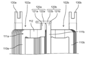
- FIGS. 5A, 5B and 6 the first engaging portion 122a of the first terminal portion 120a of the first molding coil 101a and the second engagement portion 120b of the third terminal portion 120b of the second molding coil 101b.
- the joint portion 122b may have a stepped portion that fits each other.
- FIG. 5A is an enlarged view of two adjacent molded coils in the stator according to the first modification.
- FIG. 5B is a top view of two adjacent molded coils in the stator according to the first modification.
- FIG. 6 is a diagram showing a state when two adjacent molded coils in the stator according to the first modification are connected.
- the first molded coil 101a has a stepped portion that fits into the stepped portion of the second engaging portion 122b of the second molded coil 101b.
- the second molded coil 101b may have a stepped portion that fits into the stepped portion of the first engaging portion 122a of the first molded coil 101a.
- the first engaging portion 122a and the second engaging portion 122b are engaged by fitting the stepped portion of the first engaging portion 122a and the stepped portion of the second engaging portion 122b. Can be made to. Also in this case, the first engaging portion 122a and the second engaging portion 122b can be fitted together by the concave-convex structure. Therefore, the first engaging portion 122a and the second engaging portion 122b can be easily engaged and joined. Therefore, the connection between the first forming coil 101a and the second forming coil 101b can be easily performed without using a connecting member such as a bus bar.
- the first engaging portion 122a of the first molded coil 100a and the second engaging portion 122b of the second molded coil 100b have a structure of being fitted in the circumferential direction of the stator 10. , Not limited to this.
- FIGS. 7A and 7B the first engaging portion 122a of the first forming coil 102a and the second engaging portion 122b of the second forming coil 102b have a structure that fits in the radial direction of the stator 10. May be.
- FIG. 7A is an enlarged view of two adjacent molded coils in the stator according to the modified example 2.
- FIG. 7B is a top view of two adjacent molded coils in the stator according to the modified example 2.
- a recess is formed in the first engaging portion 122a of the first forming coil 102a.
- a convex portion is formed on the second engaging portion 122b of the second forming coil 102b.
- first engaging portion 122a and the second engaging portion 122b are fitted together. With this structure, it is possible to easily connect the first forming coil 102a and the second forming coil 102b without using a connecting member such as a bus bar.
- FIG. 8 is a diagram showing a state when two adjacent molded coils in the stator according to the modified example 2 are connected.
- a recess recessed downward is formed in the first engaging portion 122a of the first forming coil 102a.
- a convex portion protruding upward is formed in the second engaging portion 122b of the second forming coil 102b.
- the convex portion of the portion 122b can be fitted.
- FIG. 9 is a diagram showing a configuration of two adjacent molded coils in the stator according to the modified example 3 and a state when the two molded coils are connected.
- the structure in which the first engaging portion 122a and the second engaging portion 122b are fitted may be a combination of a hole portion and a convex portion. Specifically, a hole is formed in the first engaging portion 122a of the first forming coil 103a.
- a convex portion is formed on the second engaging portion 122b of the second forming coil 103b.
- the connection between the first forming coil 103a and the second forming coil 103b can be easily performed without using a connecting member such as a bus bar.
- the hole portion is a through hole, but it does not have to penetrate as long as it has a shape in which the convex portion is inserted and engages with the convex portion. As an example, as shown in FIG. 9, a hole portion penetrating in the radial direction is formed in the first engaging portion 122a of the first forming coil 103a.
- a convex portion protruding in the circumferential direction is formed in the second engaging portion 122b of the second forming coil 103b.
- FIG. 10 is a diagram showing the configuration of two adjacent molded coils in the stator according to the modified example 4.
- the first terminal portion 120a of the first forming coil 104a may be provided with a partially bent portion 123a in addition to the lead portion 121a and the first engaging portion 122a. That is, the first terminal portion 120a may have a lead portion 121a, a first engaging portion 122a, and a bent portion 123a.
- the bent portion 123a is formed between the tip portion and the root portion of the first terminal portion 120a. Specifically, the bent portion 123a is provided between the lead portion 121a and the first engaging portion 122a. One end of the bent portion 123a and the lead portion 121a are connected to each other. The other end of the bent portion 123a and the first engaging portion 122a are connected to each other. The bent portion 123a is formed so as to bend at about 90 ° at one location in the central portion.
- the second engaging portion 122b of the second forming coil 104b is formed with a recess that is recessed upward.
- the first engaging portion 122a of the first forming coil 104a is adapted to fit into the second engaging portion 122b.
- the first engaging portion 122a is fitted into the concave portion of the second engaging portion 122b by bending the root of the bent portion 123a.
- the first engaging portion 122a may be fitted into the recess of the second engaging portion 122b without bending the root of the bent portion 123a.
- first engaging portion 122a and the second engaging portion 122b are fitted together by the concave-convex structure.
- this structure it is possible to easily connect the first forming coil 104a and the second forming coil 104b without using a connecting member such as a bus bar.
- FIG. 11A is a diagram showing a state when the two molded coils shown in FIG. 10 are connected.
- FIG. 11B is another diagram showing a state when the two forming coils shown in FIG. 10 are connected.
- FIG. 11C is another diagram showing a state when the two forming coils shown in FIG. 10 are connected.
- the first terminal portion 120a has a bent portion 123a.
- the bent portion 123a is bent at an acute angle.
- FIG. 11B the bent portion 123a is bent at an obtuse angle.
- the distance between the first forming coil 104a and the second forming coil 104b is widened from FIG. 11A.
- a portion where the bent portion 123a is in a straight line with the first forming coil 104a is provided.
- the first engaging portion 122a can be fitted to the second engaging portion 122b.
- the misalignment between the first forming coil 104a and the second forming coil 104b can be absorbed by the bent portion 123a.
- FIG. 12 is a diagram showing another configuration of the molded coil according to the modified example 4.
- the cutout portion 124 may be provided not only at the bent portion but also at the base of the bent portion 123a (that is, the connecting portion between the bent portion 123a and the lead portion 121a), or the tip portion of the bent portion 123a (that is, the tip portion). It may be provided at the connection portion between the bent portion 123a and the first engaging portion 122a).
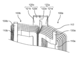
- FIG. 13 is a perspective view of the stator 10A according to the modified example 5.
- FIG. 14 is an enlarged view of two adjacent molded coils in the stator 10A according to the modified example 5.
- the first terminal portion 120a and the third terminal portion 120b are located on the outer portion of the stator 10. It may be arranged in.
- a concave portion or a hole is formed in the first engaging portion 122a of the first molded coil 100a, and a convex portion is formed in the second engaging portion 122b of the second molded coil 100b, but the present invention is not limited to this.
- a convex portion may be formed in the first engaging portion 122a of the first forming coil 100a, and a concave portion or a hole portion may be formed in the second engaging portion 122b of the second forming coil 100b.
- the number of slots in the stator 10 was 12, but it is not limited to this.
- the number of magnetic poles of the rotor 20 was 10 (that is, the number of permanent magnets 22 was 10), but the number is not limited to this. Any number can be applied to the number of slots of the stator 10 and the number of magnetic poles of the rotor 20.
- the rotor 20 was an IPM rotor, but it is not limited to this.
- a surface magnet type rotor SPM (Surface Permanent Magnetic) rotor) in which a plurality of permanent magnets are provided on the outer surface of the rotor core may be used.
- the motor 1 was illustrated as a rotary electric machine, but it is not limited to this.
- the rotary electric machine using the molded coil may be a generator.
- the technology disclosed in this disclosure can be widely used in various products using molded coils, including rotary electric machines such as electric motors.
Landscapes
- Engineering & Computer Science (AREA)
- Power Engineering (AREA)
- Windings For Motors And Generators (AREA)
- Manufacture Of Motors, Generators (AREA)
Priority Applications (4)
| Application Number | Priority Date | Filing Date | Title |
|---|---|---|---|
| EP21825762.4A EP4170870A4 (en) | 2020-06-17 | 2021-05-24 | MOLDING COIL, STATOR AND ROTARY ELECTRIC MACHINE |
| CN202180042845.5A CN115699525A (zh) | 2020-06-17 | 2021-05-24 | 成形线圈、定子及旋转电机 |
| US18/000,677 US12308718B2 (en) | 2020-06-17 | 2021-05-24 | Molded coil, stator, and rotary electric machine |
| JP2022532424A JP7649940B2 (ja) | 2020-06-17 | 2021-05-24 | 成形コイル、ステータ及び回転電機 |
Applications Claiming Priority (2)
| Application Number | Priority Date | Filing Date | Title |
|---|---|---|---|
| JP2020-104379 | 2020-06-17 | ||
| JP2020104379 | 2020-06-17 |
Publications (1)
| Publication Number | Publication Date |
|---|---|
| WO2021256178A1 true WO2021256178A1 (ja) | 2021-12-23 |
Family
ID=79267844
Family Applications (1)
| Application Number | Title | Priority Date | Filing Date |
|---|---|---|---|
| PCT/JP2021/019499 Ceased WO2021256178A1 (ja) | 2020-06-17 | 2021-05-24 | 成形コイル、ステータ及び回転電機 |
Country Status (5)
| Country | Link |
|---|---|
| US (1) | US12308718B2 (https=) |
| EP (1) | EP4170870A4 (https=) |
| JP (1) | JP7649940B2 (https=) |
| CN (1) | CN115699525A (https=) |
| WO (1) | WO2021256178A1 (https=) |
Cited By (1)
| Publication number | Priority date | Publication date | Assignee | Title |
|---|---|---|---|---|
| WO2025150319A1 (ja) * | 2024-01-12 | 2025-07-17 | パナソニックIpマネジメント株式会社 | 巻線構造体、電動機及び巻線構造体の製造方法 |
Citations (5)
| Publication number | Priority date | Publication date | Assignee | Title |
|---|---|---|---|---|
| JP2000041365A (ja) | 1998-07-21 | 2000-02-08 | Hitachi Ltd | 電動機並びに電動機用ステータの製造方法 |
| JP2010028889A (ja) * | 2008-07-15 | 2010-02-04 | Honda Motor Co Ltd | 回転電機 |
| JP2010226841A (ja) * | 2009-03-23 | 2010-10-07 | Toyota Motor Corp | 回転電機 |
| CN203850945U (zh) * | 2013-10-07 | 2014-09-24 | 江门市地尔汉宇电器股份有限公司 | 一种带连接器件附件的排水泵电机 |
| CN210517936U (zh) * | 2019-09-30 | 2020-05-12 | 汉宇集团股份有限公司 | 一种带温控器的线圈组件及排水泵 |
Family Cites Families (9)
| Publication number | Priority date | Publication date | Assignee | Title |
|---|---|---|---|---|
| JP5245782B2 (ja) * | 2008-12-09 | 2013-07-24 | トヨタ自動車株式会社 | 回転電機 |
| JP5704394B2 (ja) * | 2010-03-31 | 2015-04-22 | 株式会社デンソー | 回転電機の固定子 |
| EP2827475B1 (en) * | 2012-03-13 | 2018-06-20 | Panasonic Corporation | Motor and method for manufacturing the stator therefor |
| JP6033582B2 (ja) * | 2012-06-22 | 2016-11-30 | アイシン・エィ・ダブリュ株式会社 | ステータおよびステータの製造方法 |
| JP6075175B2 (ja) * | 2013-04-15 | 2017-02-08 | 日立金属株式会社 | モータ用接続部材及びモータ装置 |
| JP6011437B2 (ja) * | 2013-04-25 | 2016-10-19 | 日立金属株式会社 | 電動機の製造方法 |
| JP6244997B2 (ja) * | 2014-03-11 | 2017-12-13 | 株式会社豊田自動織機 | バスバーの取付構造 |
| KR102064770B1 (ko) * | 2018-02-28 | 2020-01-13 | 한국생산기술연구원 | 점적률 극대화를 위한 3차원 형상을 가지는 평각형 코일 및 이를 포함하는 전동기 |
| JP7045225B2 (ja) * | 2018-03-12 | 2022-03-31 | 本田技研工業株式会社 | 回転電機のステータ |
-
2021
- 2021-05-24 CN CN202180042845.5A patent/CN115699525A/zh active Pending
- 2021-05-24 WO PCT/JP2021/019499 patent/WO2021256178A1/ja not_active Ceased
- 2021-05-24 EP EP21825762.4A patent/EP4170870A4/en active Pending
- 2021-05-24 US US18/000,677 patent/US12308718B2/en active Active
- 2021-05-24 JP JP2022532424A patent/JP7649940B2/ja active Active
Patent Citations (5)
| Publication number | Priority date | Publication date | Assignee | Title |
|---|---|---|---|---|
| JP2000041365A (ja) | 1998-07-21 | 2000-02-08 | Hitachi Ltd | 電動機並びに電動機用ステータの製造方法 |
| JP2010028889A (ja) * | 2008-07-15 | 2010-02-04 | Honda Motor Co Ltd | 回転電機 |
| JP2010226841A (ja) * | 2009-03-23 | 2010-10-07 | Toyota Motor Corp | 回転電機 |
| CN203850945U (zh) * | 2013-10-07 | 2014-09-24 | 江门市地尔汉宇电器股份有限公司 | 一种带连接器件附件的排水泵电机 |
| CN210517936U (zh) * | 2019-09-30 | 2020-05-12 | 汉宇集团股份有限公司 | 一种带温控器的线圈组件及排水泵 |
Non-Patent Citations (1)
| Title |
|---|
| See also references of EP4170870A4 |
Cited By (1)
| Publication number | Priority date | Publication date | Assignee | Title |
|---|---|---|---|---|
| WO2025150319A1 (ja) * | 2024-01-12 | 2025-07-17 | パナソニックIpマネジメント株式会社 | 巻線構造体、電動機及び巻線構造体の製造方法 |
Also Published As
| Publication number | Publication date |
|---|---|
| US20230299630A1 (en) | 2023-09-21 |
| CN115699525A (zh) | 2023-02-03 |
| US12308718B2 (en) | 2025-05-20 |
| JP7649940B2 (ja) | 2025-03-24 |
| EP4170870A4 (en) | 2023-11-29 |
| JPWO2021256178A1 (https=) | 2021-12-23 |
| EP4170870A1 (en) | 2023-04-26 |
Similar Documents
| Publication | Publication Date | Title |
|---|---|---|
| US7821175B2 (en) | Stator assembly for an electric machine and method of manufacturing the same | |
| JP5635470B2 (ja) | 回転電機および回転電機の製造方法 | |
| JP3800371B2 (ja) | 回転電機 | |
| JP5519808B2 (ja) | ステータおよびこのステータを備える回転電機 | |
| JP6771537B2 (ja) | アキシャルギャップ型回転電機 | |
| US20190372408A1 (en) | Rotating electric machine | |
| CN106464059B (zh) | 定子线圈、定子、电磁装置及定子线圈的制造方法 | |
| EP2639933A1 (en) | Dynamo-electric machine | |
| JP2003250252A (ja) | 電動機の製造方法 | |
| CN113939979B (zh) | 线圈和具有该线圈的定子、转子、电动机以及线圈的制造方法 | |
| JPWO2020255614A5 (https=) | ||
| US20080036323A1 (en) | Permanent Magnet Synchronous Machine with Flat-Wire Windings | |
| CN115336142A (zh) | 旋转电机的定子 | |
| JP2011223652A (ja) | 回転電機巻線及び回転電機構成部材 | |
| JP6498536B2 (ja) | コアおよび回転電機 | |
| JP2009055750A (ja) | Pmクローポール型モータとその製作方法 | |
| JP2013207946A (ja) | 回転電機 | |
| JP6009519B2 (ja) | 回転電機および回転電機の製造方法 | |
| JP7649940B2 (ja) | 成形コイル、ステータ及び回転電機 | |
| JP4178558B2 (ja) | 回転電機 | |
| JP2003143822A (ja) | 誘導電動機 | |
| JP2003153472A (ja) | 回転電機及び電磁機器 | |
| JPWO2021256178A5 (https=) | ||
| WO2024034364A1 (ja) | コイル、ステータ及び回転電機 | |
| JP4713219B2 (ja) | ステータの組立方法 |
Legal Events
| Date | Code | Title | Description |
|---|---|---|---|
| 121 | Ep: the epo has been informed by wipo that ep was designated in this application |
Ref document number: 21825762 Country of ref document: EP Kind code of ref document: A1 |
|
| ENP | Entry into the national phase |
Ref document number: 2022532424 Country of ref document: JP Kind code of ref document: A |
|
| NENP | Non-entry into the national phase |
Ref country code: DE |
|
| ENP | Entry into the national phase |
Ref document number: 2021825762 Country of ref document: EP Effective date: 20230117 |
|
| WWG | Wipo information: grant in national office |
Ref document number: 18000677 Country of ref document: US |
|
| WWW | Wipo information: withdrawn in national office |
Ref document number: 2021825762 Country of ref document: EP |