WO2021256178A1 - Molding coil, stator, and rotary electric machine - Google Patents
Molding coil, stator, and rotary electric machine Download PDFInfo
- Publication number
- WO2021256178A1 WO2021256178A1 PCT/JP2021/019499 JP2021019499W WO2021256178A1 WO 2021256178 A1 WO2021256178 A1 WO 2021256178A1 JP 2021019499 W JP2021019499 W JP 2021019499W WO 2021256178 A1 WO2021256178 A1 WO 2021256178A1
- Authority
- WO
- WIPO (PCT)
- Prior art keywords
- coil
- winding
- stator
- terminal
- terminal portion
- Prior art date
Links
- 238000000465 moulding Methods 0.000 title claims abstract description 43
- 238000004804 winding Methods 0.000 claims abstract description 141
- 239000004020 conductor Substances 0.000 claims abstract description 54
- 238000005304 joining Methods 0.000 claims description 7
- 238000000034 method Methods 0.000 claims description 6
- 230000004048 modification Effects 0.000 description 19
- 238000012986 modification Methods 0.000 description 19
- 238000010586 diagram Methods 0.000 description 10
- 230000004907 flux Effects 0.000 description 10
- 229910000831 Steel Inorganic materials 0.000 description 7
- 239000010959 steel Substances 0.000 description 7
- 238000005452 bending Methods 0.000 description 5
- RYGMFSIKBFXOCR-UHFFFAOYSA-N Copper Chemical compound [Cu] RYGMFSIKBFXOCR-UHFFFAOYSA-N 0.000 description 3
- 229910000976 Electrical steel Inorganic materials 0.000 description 3
- 229910052802 copper Inorganic materials 0.000 description 3
- 239000010949 copper Substances 0.000 description 3
- 238000003780 insertion Methods 0.000 description 3
- 230000037431 insertion Effects 0.000 description 3
- 238000010030 laminating Methods 0.000 description 3
- WABPQHHGFIMREM-UHFFFAOYSA-N lead(0) Chemical compound [Pb] WABPQHHGFIMREM-UHFFFAOYSA-N 0.000 description 3
- 238000003466 welding Methods 0.000 description 3
- XEEYBQQBJWHFJM-UHFFFAOYSA-N Iron Chemical group [Fe] XEEYBQQBJWHFJM-UHFFFAOYSA-N 0.000 description 2
- 239000012212 insulator Substances 0.000 description 2
- 239000000696 magnetic material Substances 0.000 description 2
- 229910052751 metal Inorganic materials 0.000 description 2
- 239000002184 metal Substances 0.000 description 2
- 239000007769 metal material Substances 0.000 description 2
- 238000007493 shaping process Methods 0.000 description 2
- 230000001154 acute effect Effects 0.000 description 1
- 229910052782 aluminium Inorganic materials 0.000 description 1
- XAGFODPZIPBFFR-UHFFFAOYSA-N aluminium Chemical compound [Al] XAGFODPZIPBFFR-UHFFFAOYSA-N 0.000 description 1
- 238000005266 casting Methods 0.000 description 1
- 239000011248 coating agent Substances 0.000 description 1
- 238000000576 coating method Methods 0.000 description 1
- 238000005516 engineering process Methods 0.000 description 1
- 238000009413 insulation Methods 0.000 description 1
- 230000003993 interaction Effects 0.000 description 1
- 239000000463 material Substances 0.000 description 1
- 230000000149 penetrating effect Effects 0.000 description 1
- 238000003825 pressing Methods 0.000 description 1
- 230000008569 process Effects 0.000 description 1
- 238000005476 soldering Methods 0.000 description 1
- 230000001360 synchronised effect Effects 0.000 description 1
Images


Classifications
-
- H—ELECTRICITY
- H02—GENERATION; CONVERSION OR DISTRIBUTION OF ELECTRIC POWER
- H02K—DYNAMO-ELECTRIC MACHINES
- H02K3/00—Details of windings
- H02K3/04—Windings characterised by the conductor shape, form or construction, e.g. with bar conductors
- H02K3/18—Windings for salient poles
-
- H—ELECTRICITY
- H01—ELECTRIC ELEMENTS
- H01F—MAGNETS; INDUCTANCES; TRANSFORMERS; SELECTION OF MATERIALS FOR THEIR MAGNETIC PROPERTIES
- H01F5/00—Coils
- H01F5/04—Arrangements of electric connections to coils, e.g. leads
-
- H—ELECTRICITY
- H02—GENERATION; CONVERSION OR DISTRIBUTION OF ELECTRIC POWER
- H02K—DYNAMO-ELECTRIC MACHINES
- H02K1/00—Details of the magnetic circuit
- H02K1/06—Details of the magnetic circuit characterised by the shape, form or construction
- H02K1/12—Stationary parts of the magnetic circuit
- H02K1/16—Stator cores with slots for windings
-
- H—ELECTRICITY
- H02—GENERATION; CONVERSION OR DISTRIBUTION OF ELECTRIC POWER
- H02K—DYNAMO-ELECTRIC MACHINES
- H02K3/00—Details of windings
- H02K3/04—Windings characterised by the conductor shape, form or construction, e.g. with bar conductors
- H02K3/12—Windings characterised by the conductor shape, form or construction, e.g. with bar conductors arranged in slots
-
- H—ELECTRICITY
- H02—GENERATION; CONVERSION OR DISTRIBUTION OF ELECTRIC POWER
- H02K—DYNAMO-ELECTRIC MACHINES
- H02K3/00—Details of windings
- H02K3/04—Windings characterised by the conductor shape, form or construction, e.g. with bar conductors
- H02K3/28—Layout of windings or of connections between windings
-
- Y—GENERAL TAGGING OF NEW TECHNOLOGICAL DEVELOPMENTS; GENERAL TAGGING OF CROSS-SECTIONAL TECHNOLOGIES SPANNING OVER SEVERAL SECTIONS OF THE IPC; TECHNICAL SUBJECTS COVERED BY FORMER USPC CROSS-REFERENCE ART COLLECTIONS [XRACs] AND DIGESTS
- Y02—TECHNOLOGIES OR APPLICATIONS FOR MITIGATION OR ADAPTATION AGAINST CLIMATE CHANGE
- Y02T—CLIMATE CHANGE MITIGATION TECHNOLOGIES RELATED TO TRANSPORTATION
- Y02T10/00—Road transport of goods or passengers
- Y02T10/60—Other road transportation technologies with climate change mitigation effect
- Y02T10/64—Electric machine technologies in electromobility
Definitions
- the present disclosure relates to a rotary electric machine including an electric machine, a stator used in the rotary electric machine, and a molded coil used as a winding coil of the stator.
- Electric machines As one of the rotary electric machines, an electric machine that converts electric energy into mechanical energy is known.
- Motors are used in various products such as household equipment or industrial equipment.
- electric motors are widely used in automobiles, robots, and the like, as well as home appliances such as vacuum cleaners.
- Patent Document 1 discloses an electric motor using a molded coil molded to fit the slot shape of a stator.
- the winding coil is arranged in the slot of the stator.
- a plurality of winding coils arranged in the slots of the stator are electrically connected to each other by being connected.
- the round wire coil configured by the round wire can freely route the round wire drawn from the winding portion, in the stator using the round wire coil as the winding coil, a plurality of round wires arranged in the slot.
- the round wire coils can be easily connected to each other.
- the molded coil is composed of a plate-shaped conductor having high rigidity. Therefore, in the stator using the molded coil as the winding coil, it is not possible to easily connect the plurality of molded coils arranged in the slots to each other as compared with the case of using the round wire coil.
- a winding portion in which plate frame-shaped conductors are laminated a first terminal portion protruding from the first turn (winding start) portion of the winding portion, and a final turn (winding) of the winding portion.
- Those having a second terminal portion protruding from the end) portion are known.
- the positions of the first terminal portion and the second terminal portion in each molded coil are different in the radial direction of the stator. That is, the positions of the first terminal portion and the second terminal portion in each molded coil do not exist at equidistant positions from the center of the stator. That is, the first terminal portion and the second terminal portion are not located on the same circumference.
- a connecting member such as a bus bar.
- a bus bar is bridged between two adjacent molded coils, and the first terminal portion of one of the two molded coils and one end of the bus bar are joined to each other, and the two molded coils are joined. The second terminal portion of the other molded coil and the other end portion of the bus bar are joined.
- the present disclosure provides a molded coil, a stator using the molded coil, and a rotary electric machine using the stator, which can easily connect two molded coils without using a connecting member such as a bus bar. The purpose.
- one aspect of the molded coil according to the present disclosure is one of two molded coils arranged adjacent to each other, from the first turn to the nth turn (n is).
- a first having a winding portion in which conductors are laminated with (2 or more integers) and a lead portion extending from the first turn of the winding portion in a direction orthogonal to the stacking direction of the conductors in the winding portion.
- the first terminal portion includes a terminal portion and a second terminal portion having a lead portion extending in a direction orthogonal to the stacking direction of the conductor in the winding portion from the nth turn portion of the winding portion.
- a first engaging portion that engages with a second engaging portion formed at the tip of the terminal portion of the other molded coil of the two molded coils is formed at the tip of the terminal portion.
- one aspect of the stator according to the present disclosure includes a core having a plurality of teeth and a plurality of molded coils each wound around the plurality of teeth, and the plurality of molded coils are the first molded coil.
- the n 1 turns from the first turn (n 1 is an integer of 2 or more) first conductor
- a lead portion extending in a direction orthogonal to the stacking direction of the first conductor in the first winding portion from the first turn portion of the first winding portion and the first winding portion in which the first winding portion is laminated.
- the second having a first terminal portion, the lead portion extending in a direction perpendicular to the stacking direction of the first conductor from said portion of said n 1 turn of the first winding part of the first winding portion having has a terminal portion, said second forming coil has a second winding section first n 2 turns from the first turn (n 2 is an integer greater than or equal to 2) of the second conductor in stacked, the second A third terminal portion having a lead portion extending in a direction orthogonal to the stacking direction of the second conductor in the second winding portion from the first turn portion of the winding portion, and the second winding portion.
- a first engaging portion is formed at the tip portion, and a second engaging portion that engages with the first engaging portion is formed at the tip portion of the third terminal portion.
- the 1-terminal portion and the third terminal portion are connected by joining the first engaging portion and the second engaging portion.
- one aspect of the rotary electric machine according to the present disclosure includes the above-mentioned stator and a rotor that rotates by the magnetic force of the stator.
- FIG. 1 It is sectional drawing of the electric motor which concerns on embodiment. It is a perspective view of the stator in the electric motor which concerns on embodiment. It is an enlarged view of two adjacent molded coils in the stator of the motor which concerns on embodiment. It is a top view of two adjacent molded coils in the stator of the motor which concerns on embodiment. It is a figure which shows the state at the time of connecting two adjacent molded coils in the stator of the electric motor which concerns on embodiment. It is an enlarged view of two adjacent molded coils in the stator which concerns on modification 1. FIG. It is a top view of two adjacent molded coils in the stator which concerns on modification 1. FIG. It is a figure which shows the state at the time of connecting two adjacent molding coils in the stator which concerns on modification 1.
- FIG. It is an enlarged view of two adjacent molded coils in the stator which concerns on modification 2.
- FIG. It is a top view of two adjacent molded coils in the stator which concerns on modification 2.
- FIG. It is a figure which shows the state at the time of connecting two adjacent molding coils in the stator which concerns on modification 2.
- FIG. It is a figure which shows the structure of two adjacent forming coils in the stator which concerns on modification 3 and the state when the two forming coils are connected.
- FIG. 10 It is another figure which shows the state when the two forming coils shown in FIG. 10 are connected.
- FIG. 10 It is another figure which shows the state when the two forming coils shown in FIG. 10 are connected. It is a figure which shows the other structure of the molded coil which concerns on modification 4. It is a perspective view of the stator which concerns on modification 5. FIG. It is an enlarged view of two adjacent molded coils in the stator which concerns on modification 5. FIG.
- the radial direction of the stator 10 and the rotor 20 is the "radial direction”
- the rotation direction of the rotor 20 is the "circumferential direction”. That is, the direction extending from the axis C around the axis C of the rotating shaft 23 is the "diameter direction", and the direction rotating around the axis C around the axis C of the rotating shaft 23 is the "circumferential direction”. .. Therefore, the "diametrical direction” is a direction orthogonal to the direction of the axis C of the rotating shaft 23.
- the terms “upper” and “lower” do not necessarily refer to the upward direction (vertically upward) and the downward direction (vertically downward) in absolute spatial recognition.
- FIG. 1 is a cross-sectional view of the electric motor 1 according to the embodiment.
- FIG. 2 is a perspective view of the stator 10 in the motor 1. Note that FIG. 1 shows a cross section when cut in a plane orthogonal to the direction of the axis C of the rotating shaft 23 of the rotor 20.
- the motor 1 includes a stator 10 and a rotor 20.
- the stator 10 and the rotor 20 are arranged so as to face each other.
- the electric motor 1 is an inner rotor type motor in which the rotor 20 is arranged inside the stator 10.
- the motor 1 also has parts such as a bearing that supports the motor case and the rotating shaft 23, but for convenience, the illustration and description of the parts will be omitted.
- the stator 10 (stator) is arranged between the stator and the rotor 20 so as to face the rotor 20 via an air gap. There is a small air gap between the surface of the rotor 20 and the surface of the stator 10. In the present embodiment, the stator 10 is arranged so as to surround the rotor core 21 of the rotor 20.
- the stator 10 generates a magnetic force acting on the rotor 20.
- the stator 10 is configured to generate a magnetic flux on the air gap surface of the rotor 20 with the rotor core 21.
- the stator 10 is configured such that N poles and S poles are alternately and repeatedly generated in the circumferential direction on the surface facing the air gap with the rotor core 21.
- the stator 10 has a molded coil 100 and a stator core 200.
- the molded coil 100 is a stator coil provided on the stator 10 as a winding coil.
- the forming coil 100 is an armature winding of the stator 10, and is wound around the stator core 200. Specifically, the forming coil 100 is wound around each of the plurality of teeth 210 of the stator 10. Therefore, a plurality of molded coils 100 are used for the stator 10.
- the plurality of molded coils 100 are each wound around a plurality of teeth 210.
- the plurality of molded coils 100 are arranged at equal intervals along the circumferential direction so as to surround the rotor 20. Each molded coil 100 is housed in the slot 230 of the stator 10.
- the forming coil 100 may be wound around the teeth 210 via an insulating member (not shown) such as an insulator or insulating paper. In this case, the forming coil 100 is wound around an insulator mounted on the teeth 210, for example.
- the molded coil 100 is configured by laminating plate-shaped conductors, unlike a round wire coil using a round wire.
- the molded coil 100 has a higher space factor than the round wire coil.
- the space factor of the molded coil 100 is 90% or more.
- the forming coil 100 is formed, for example, by preparing a plurality of rectangular plates having different lengths, widths, and thicknesses, pressing the plates, and joining them by cold pressure welding, welding, or other methods. be able to.
- the plate material for example, a metal plate made of a low resistance metal material such as copper or aluminum can be used.
- the molded coil 100 may be formed by so-called casting, in which a metal material such as copper is melted and poured into a mold. Further, it may be formed by bending a plate-shaped conducting wire having a width or a thickness different in the middle at a predetermined position. Further, a plate-shaped conductor having a constant width and thickness may be rolled at a predetermined portion, the width or thickness may be changed in the middle, and then the conductor may be spirally wound. That is, the forming coil 100 can be formed by adding another process other than winding the conductor, or by using a method different from simply winding the lead wire.
- the shape of the forming coil 100 and the joining structure between the forming coils 100 will be described later.
- the stator core 200 is an iron core that is the core of the stator 10.
- the stator core 200 is composed of a plurality of teeth 210 and an annular yoke 220.
- Each of the plurality of teeth 210 projects toward the axis C of the rotating shaft 23 of the rotor 20. Specifically, the plurality of teeth 210 are provided radially in a direction (diametrical direction) orthogonal to the axis C of the rotating shaft 23.
- a slot 230 for arranging the forming coil 100 is formed between two adjacent teeth 210. That is, the slot 230 of the stator 10 corresponds between two adjacent teeth 210.
- the plurality of teeth 210 are arranged at equal intervals along the circumferential direction while forming slots 230 between two adjacent teeth 210.
- the number of slots of the stator 10 is 12. Therefore, 12 molding coils 100 are used.
- each tooth 210 extends radially inward from the annular yoke 220. That is, the yoke 220 is a back yoke formed on the outside of each tooth 210. Each tooth 210 is fitted and fixed to the yoke 220.
- Each of the teeth 210 and the yoke 220 is a laminated body formed by laminating a plurality of electromagnetic steel sheets.
- Each of the plurality of electromagnetic steel sheets is, for example, a punched steel sheet formed into a predetermined shape.
- the teeth 210 and the yoke 220 are separate bodies, they may be integrated as one stator core 200. Even when the teeth 210 and the yoke 220 are integrated, the stator core 200 is a laminated body formed by laminating a plurality of electromagnetic steel sheets.
- the teeth 210 and the yoke 220 are not limited to a laminated body of a plurality of electrical steel sheets, whether they are separate bodies or integrally, and may be a bulk body made of a magnetic material. good.
- the plurality of teeth 210 are magnetic pole teeth, and a magnetic force is generated by energization of the forming coil 100.
- the plurality of forming coils 100 in the stator 10 are electrically connected as a three-phase winding so that the rotor 20 rotates as a three-phase synchronous motor.
- the plurality of molded coils 100 are composed of unit coils of each of the three phases of U phase, V phase and W phase, which are electrically different in phase by 120 degrees from each other. That is, the molded coil 100 mounted on each tooth 210 is energized and driven by a three-phase alternating current that is energized in units of U phase, V phase, and W phase. As a result, the main magnetic flux of the stator 10 is generated in each tooth 210.
- the 12 forming coils 100 have four U-phase coils U1 to U4 and four V-phase coils V1 to V4 according to the phase of the current flowing through each forming coil 100. It is divided into four W-phase coils W1 to W4 and arranged in a predetermined slot 230.
- the four U-phase coils U1 to U4 are connected in series.
- the four V-phase coils V1 to V4 are connected in series.
- the four W-phase coils W1 to W4 are also connected in series.
- the rotor 20 (rotor) is rotated by the magnetic force of the stator 10.
- the rotor 20 also generates a magnetic force.
- the rotor 20 has a configuration in which a plurality of N poles and S poles that generate magnetic flux in the circumferential direction are alternately and repeatedly present.
- the rotor 20 generates a magnetic force acting on the stator 10.
- the direction of the magnetic flux generated from the rotor 20 is a direction orthogonal to the direction of the axis C of the rotating shaft 23 (direction of the axis). That is, the direction of the magnetic flux generated by the rotor 20 is the radial direction (diameter direction).
- the rotor 20 has a rotor core 21, a plurality of permanent magnets 22, and a rotating shaft 23.
- the rotor 20 rotates about the axis C of the rotating shaft 23 as the center of rotation. That is, the rotation shaft 23 becomes the central axis when the rotor 20 rotates.
- the rotor 20 is a permanent magnet embedded rotor (IPM (Interior Permanent Magnet) rotor) in which the permanent magnet 22 is embedded in the rotor core 21. Therefore, the electric motor 1 in the present embodiment is an IPM motor.
- IPM Interior Permanent Magnet
- the rotor core 21 is an iron core that is the core of the rotor 20.
- the rotor core 21 is a laminated body in which a plurality of electrical steel sheets are laminated in the direction of the axial center C of the rotating shaft 23 (axial center direction).
- Each of the plurality of electromagnetic steel sheets is, for example, a punched steel sheet formed into a predetermined shape.
- a plurality of electrical steel sheets are fixed to each other by, for example, caulking.
- the rotor core 21 is not limited to a laminated body of a plurality of electromagnetic steel sheets, but may be a bulk body made of a magnetic material.
- the permanent magnet 22 is arranged in the magnet insertion hole provided in the rotor core 21.
- the rotor core 21 is provided with 10 magnet insertion holes.
- a plate-shaped permanent magnet 22 is inserted into each magnet insertion hole.
- the permanent magnet 22 is a sintered magnet.
- the permanent magnet 22 may be a bond magnet.
- the rotating shaft 23 is a long shaft, for example, a metal rod.
- the rotating shaft 23 is fixed to the rotor core 21. Specifically, the rotating shaft 23 is inserted into a through hole provided in the center of the rotor core 21 and fixed to the rotor core 21 so as to extend on both sides of the rotor core 21 in the direction of the axis C.
- the rotary shaft 23 is fixed to the rotor core 21 by, for example, press-fitting or shrink-fitting into the through hole of the rotor core 21.
- one of the portions of the rotating shaft 23 protruding from the rotor core 21 functions as an output shaft.
- a load such as a rotating fan is attached to the rotating shaft 23.
- the rotary shaft 23 is rotatably supported by a bearing such as a bearing.
- a field current flows through the forming coil 100 and a magnetic field is generated in the stator 10.
- a magnetic flux from the stator 10 to the rotor 20 is generated.
- a magnetic flux is generated from each of the teeth 210 of the stator core 200 of the stator 10 toward the rotor 20.
- a magnetic flux passing through the stator 10 is generated by the permanent magnets 22 arranged in the rotor core 21.
- the magnetic force generated by the interaction between the magnetic flux generated by the stator 10 and the magnetic flux generated by the permanent magnet 22 of the rotor 20 becomes the torque for rotating the rotor 20, and the rotor 20 rotates.
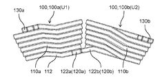
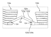
- FIG. 3A is an enlarged view of two adjacent molded coils 100 in the stator 10 of the motor 1 according to the embodiment.
- FIG. 3B is a top view of two adjacent molded coils 100 in the stator 10.
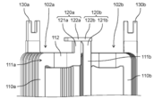
- FIG. 4 is a diagram showing a state when two adjacent forming coils 100 in the same stator 10 are connected.
- the four U-phase coils U1 to U4 shown in FIGS. 1 and 2 as the forming coil 100 are connected in series.
- Two molded coils 100 of the U-phase coil U1 and the U-phase coil U2 are arranged next to each other.
- two molded coils 100 of the U-phase coil U3 and the U-phase coil U4 are arranged next to each other.
- two molded coils 100 of the V-phase coil V1 and the V-phase coil V2 are arranged next to each other.
- Two molded coils 100 of the V-phase coil V3 and the V-phase coil V4 are arranged next to each other.
- Two molded coils 100, a W-phase coil W1 and a W-phase coil W2 are arranged next to each other.
- Two molded coils 100 of the W-phase coil W3 and the W-phase coil W4 are arranged next to each other.
- the first forming coil 100a and the second forming coil are used. It is directly connected to 100b without a connecting member such as a bus bar.
- the configuration of the molded coil 100 will be described in detail, and the structure of the joint portion of the two molded coils 100 arranged adjacent to each other will be described in detail.
- the molded coil 100 which is the U-phase coil U1 is designated as the first molded coil 100a
- the molded coil 100 which is the U-phase coil U2 is the first.
- a case where the U-phase coil U1 and the U-phase coil U2 are joined as the two forming coil 100b will be described as an example.
- the first molded coil 100a and the second molded coil 100b are composed of a plate-shaped conductor coated with an insulating coating.
- the plate-shaped first conductor constituting the first forming coil 100a and the plate-shaped second conductor constituting the second forming coil 100b both have a quadrangular cross-sectional shape and are made of copper.
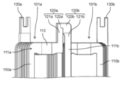
- the first forming coil 100a includes a first winding portion 110a, a first terminal portion 120a and a second terminal portion protruding upward from the first winding portion 110a. It has 130a and.
- First winding unit 110a the winding start and the first turn, the winding end first n 1 turn (n 1 is an integer of 2 or more)
- n 1 is an integer of 2 or more
- the first winding portion 110a has laminated conductors constituting the coil of n 1 turn.
- the first winding portion 110a is laminated so that a flat plate-shaped conductor is spirally wound in the thickness direction.
- the shape of the first winding portion 110a is substantially a rectangular frame shape. That is, the first winding portion 110a made of n turns of a flat conductor of the first turn to the n 1 turn, substantially rectangular annular with four sides as viewed from the radial direction of the stator 10 Is formed in.
- the first winding portion 110a is arranged so that the portion of the first turn is located at the inner portion of the stator 10 and the portion of the nth turn is located at the outer portion of the stator 10. That is, the first winding portion 110a is laminated in this order from the portion of the first turn to the portion of the nth turn 1 from the axial center C of the rotating shaft 23 toward the outer side in the radial direction.
- the first winding portion 110a is housed in the slot 230.
- the outer shape of the first winding portion 110a has a shape suitable for the slot 230.
- the interface between turns is insulated. Accordingly, the current supplied to the first winding unit 110a will flow spirally from the first turn or from the n 1 turn to first turn to the n 1 turn.
- the first terminal portion 120a and the second terminal portion 130a function as a wiring portion for electrically connecting the first forming coil 100a to other forming coils 100 other than the first forming coil 100a.
- the first terminal portion 120a is connected to the second forming coil 100b, which is the U-phase coil U2
- the second terminal portion 130a is connected to the U-phase coil U3 or the U-phase coil U4.
- the first terminal portion 120a is a portion where the conductor extends from the first turn of the first winding portion 110a.
- the first forming coil 100a has an extending portion 112 extending toward the second forming coil 100b as a part of the first winding portion 110a of the portion of the first turn, and the first terminal portion 120a has an extending portion 112. , It extends from the extension portion 112.
- the extending portion 112 extends toward the coil end 111b of the second winding portion 110b in the second forming coil 100b as a part of the coil end 111a of the first winding portion 110a.
- the first terminal portion 120a projects upward from the end portion of the extending portion 112 on the second forming coil 100b side.
- the first terminal portion 120a protruding from the first winding portion 110a has a lead portion 121a and a first engaging portion 122a.
- the lead portion 121a is a portion extending from the portion of the first turn of the first winding portion 110a in the direction orthogonal to the stacking direction of the conductors in the first winding portion 110a. In the present embodiment, the lead portion 121a extends linearly upward from the end portion of the extending portion 112 on the second forming coil 100b side.
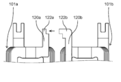
- the first engaging portion 122a has a shape that fits with the second engaging portion 122b of the second forming coil 100b. As shown in FIGS. 3A, 3B and 4, the first engaging portion 122a has a recess that fits into the second engaging portion 122b. Further, the first engaging portion 122a is formed at the tip end portion of the first terminal portion 120a. Specifically, the first engaging portion 122a is formed at the tip end portion of the lead portion 121a.
- the second terminal portion 130a is a portion where the conductor extends from the first winding portion 110a, similarly to the first terminal portion 120a.
- the second terminal portion 130a is a portion where the conductive from the n 1 turn of the first winding portion 110a extends.
- the second terminal portion 130a has a lead portion extending in a direction perpendicular to the stacking direction of the conductor at the portion of the n 1 turn of the first winding unit 110a first winding unit 110a.
- the second terminal portion 130a extends in the same direction as the first terminal portion 120a.
- the second forming coil 100b As shown in FIGS. 2, 3A, and 3B, the second forming coil 100b has a second winding portion 110b, a third terminal portion 120b and a fourth terminal protruding upward from the second winding portion 110b. It has a portion 130b.
- Second winding unit 110b a winding start first and turn the winding end when the n 2 turns (n 2 is an integer of 2 or more) that, similarly to the first winding portion 110a of the first molded coil 100a has a structure in which the conductor is laminated from the first turn to the n 2 turns. That is, the second coil portion 110b has a stacked conductors constituting the n 2 turns of the coil. Similar to the first winding portion 110a, the second winding portion 110b is laminated so that a flat plate-shaped conductor is spirally wound in the thickness direction.
- the shape of the second winding portion 110b is substantially a rectangular frame shape. That is, the second coil portion 110b made of n turns of a flat conductor of the first turn to the n 2 turns, substantially rectangular annular with four sides as viewed from the radial direction of the stator 10 Is formed in.
- the frame-shaped size of the second winding portion 110b is the same as the frame-shaped size of the first winding portion 110a.
- the frame-shaped size of the second winding portion 110b and the frame-shaped size of the first winding portion 110a may be different.
- the number of turns of the second winding portion 110b and the number of turns of the first winding portion 110a may be different.
- the second winding portion 110b, the part of the first turn in the inner portion of the stator 10, part of the n 2 turns are arranged so as to be located on the outside portion of the stator 10. That is, the second winding portion 110b is laminated in this order from the portion of the first turn to the portion of the nth turn 2 from the axial center C of the rotating shaft 23 toward the outer side in the radial direction.
- the second winding portion 110b is housed in the slot 230.
- the outer shape of the second winding portion 110b has a shape suitable for the slot 230.
- the interface between turns is insulated. Accordingly, the current supplied to the second winding unit 110b will flow spirally from the first turn or from the n 2 turns to the first turn to the n 2 turns.
- the second molded coil 100b unlike the first molded coil 100a, does not have the extending portion 112 formed in the first winding portion 110a in the second winding portion 110b.
- the second winding portion 110b has the same shape and size as the first winding portion 110a except that the extending portion 112 is not formed.
- the third terminal portion 120b and the fourth terminal portion 130b function as a wiring portion for electrically connecting the second molding coil 100b to other molding coils 100 other than the second molding coil 100b.
- the third terminal portion 120b is connected to the first forming coil 100a which is the U-phase coil U1
- the fourth terminal portion 130b is connected to the U-phase coil U3 or the U-phase coil U4.
- the third terminal portion 120b is a portion where the conductor extends from the first turn of the second winding portion 110b.
- the third terminal portion 120b protrudes from the coil end 111b of the second winding portion 110b.
- the third terminal portion 120b has a lead portion 121b and a second engaging portion 122b.
- the lead portion 121b is a portion extending from the portion of the first turn of the second winding portion 110b in the direction orthogonal to the stacking direction of the conductors in the second winding portion 110b. In the present embodiment, the lead portion 121b extends linearly upward from the coil end 111b of the second winding portion 110b.
- the second engaging portion 122b engages with the first engaging portion 122a of the first forming coil 100a.
- the second engaging portion 122b has a shape that fits with the first engaging portion 122a of the first forming coil 100a. That is, the first engaging portion 122a of the first molded coil 100a and the second engaging portion 122b of the second molded coil 100b have a shape that fits each other.
- the second engaging portion 122b since the first engaging portion 122a of the first forming coil 100a has a concave portion, the second engaging portion 122b has a convex portion that fits with the concave portion. ..
- the first terminal portion 120a of the first molded coil 100a and the third terminal portion 120b of the second molded coil 100b are connected by joining the first engaging portion 122a and the second engaging portion 122b. ..
- the first engaging portion 122a and the second engaging portion 122 are joined by welding, soldering, caulking, fusing, or the like.
- the joined first engaging portion 122a and the second engaging portion 122b are electrically and mechanically connected. Therefore, at least the joint portion between the first engaging portion 122a and the second engaging portion 122b has the insulating film covering the conductor removed.
- the second engaging portion 122b is formed at the tip end portion of the third terminal portion 120b. Specifically, the second engaging portion 122b is formed at the tip end portion of the lead portion 121b.
- the fourth terminal portion 130b similar to the third terminal portion 120b, but the conductor from the second winding portion 110b is a portion that extends, the fourth terminal part 130b includes a first n 2 of the second winding portion 110b This is the part where the conductor extends from the turn.
- the fourth terminal portion 130b includes a lead portion extending in a direction perpendicular to the portion of the n 2 turns of the second winding portion 110b and the stacking direction of the conductors in the second winding unit 110b.
- the fourth terminal portion 130b extends in the same direction as the third terminal portion 120b.
- the first forming coil 100a and the second forming coil 100b configured in this way are the first turn of the first winding portion 110a of the first forming coil 100a and the second winding portion 110b of the second forming coil 100b. It is arranged so that it is located on the same side as the first turn.
- the first turn of the first winding portion 110a and the first turn of the second winding portion 110b are the stators 10. It is arranged so as to be located in the inner part of.
- the first terminal portion 120a is provided so as to be located on the inner portion of the stator 10 and on the side of the second forming coil 100b.
- the second terminal portion 130a is provided so as to be located on the outer side of the stator 10 on the side opposite to the inside of the stator 10 and on the side opposite to the second molded coil 100b side.
- the third terminal portion 120b is provided so as to be located on the inner portion of the stator 10 and on the side of the first molded coil 100a.
- the fourth terminal portion 130b is provided so as to be located on the outer side portion of the stator 10 and on the side opposite to the first forming coil 100a side.
- first terminal portion 120a of the first molding coil 100a and the third terminal portion 120b of the second molding coil 100b are located inside the stator 10.
- the second terminal portion 130a of the first molding coil 100a and the fourth terminal portion 130b of the second molding coil 100b are located on the outer side portion of the stator 10.
- the first terminal portion 120a of the first molding coil 100a and the third terminal portion 120b of the second molding coil 100b are provided close to each other so as to be close to each other.
- the second terminal portion 130a of the first molding coil 100a and the fourth terminal portion 130b of the second molding coil 100b are provided so as to be separated from each other.
- the first terminal portion 120a and the second terminal portion 130a are substantially diagonal to each other in the first forming coil 100a. positioned. Further, in the second molded coil 100b, the third terminal portion 120b and the fourth terminal portion 130b are substantially diagonally opposite to the diagonal direction of the first terminal portion 120a and the second terminal portion 130a. Is located in.
- the first engaging portion 122a provided on the first terminal portion 120a of the first forming coil 100a and the second terminal portion 120b provided on the third terminal portion 120b of the second forming coil 100b. It is located at the same height as the engaging portion 122b.
- the first engaging portion 122a and the second engaging portion 122b are located at the same height with respect to the upper surface of the coil end 111a or 111b.
- the concave portion of the first engaging portion 122a and the convex portion of the second engaging portion 122b are located at the same height with respect to the upper surface of the coil end 111a or 111b.
- the tip portion of the first terminal portion 120a of the first molding coil 100a is attached to the tip portion of the third terminal portion 120b of the second molding coil 100b.
- a first engaging portion 122a that engages with the formed second engaging portion 122b is formed.
- the forming coil 100 is one of the two forming coils 100 arranged adjacent to each other, and is formed from the first turn to the nth turn (n is an integer of 2 or more).
- a winding portion in which conductors are laminated a first terminal portion 120a having a lead portion 121a extending in a direction orthogonal to the stacking direction of the conductors in the winding portion from the first turn of the winding portion, and a winding portion.
- a second terminal portion 130a having a lead portion extending in a direction orthogonal to the stacking direction of the conductors in the winding portion from the portion of the nth turn is provided, and two moldings are formed on the tip portion of the first terminal portion 120a.
- a first engaging portion 122a that engages with a second engaging portion 122b formed at the tip of a third terminal portion 120b of the other molded coil 100 of the coil 100 is formed.
- the first terminal portion 120a of the first molded coil 100a and the third terminal portion 120b of the second molded coil 100b are connected by joining the first engaging portion 122a and the second engaging portion 122b. ing.
- the two forming coils 100 of the first forming coil 100a and the second forming coil 100b can be directly connected and connected. This makes it possible to easily connect the two forming coils 100 of the first forming coil 100a and the second forming coil 100b without using a connecting member such as a bus bar.
- the first engaging portion 122a of the first forming coil 100a has a recess, and the second engaging portion 122b of the second forming coil 100b. Has a convex portion, and the first engaging portion 122a is engaged with the second engaging portion 122b by fitting the convex portion and the concave portion.
- the first engaging portion 122a and the second engaging portion 122b can be fitted by the concave-convex structure. Therefore, the first engaging portion 122a and the second engaging portion 122b can be easily engaged and joined. Therefore, the connection between the first forming coil 100a and the second forming coil 100b can be performed more easily.
- the first forming coil 100a has an extending portion 112 extending toward the second forming coil 100b as a part of the first winding portion 110a of the portion of the first turn.
- the first terminal portion 120a on which the first engaging portion 122a is formed extends from the tip end portion of the extending portion 112.
- the extending portion 112 is formed as a part of the coil end 111a of the first winding portion 110a.
- the first terminal portion 120a is provided via the coil end 111a, the first terminal portion 120a can be easily brought close to the third terminal portion 120b of the second molded coil 100b. Moreover, by forming the extending portion 112 using the coil end 111a, it is easy to make the first terminal portion 120a into the third terminal portion 120b without having to bend the first terminal portion 120a to form a complicated shape. Can be approached to.
- a connecting member such as a bus bar is used for the first terminal portion 120a of the first forming coil 100a which is the U-phase coil U1 and the third terminal portion 120b of the second forming coil 100b which is the U-phase coil U2. Directly connected without.
- the second terminal portion 130a of the first molding coil 100a which is the U-phase coil U1
- is the second terminal portion 130a of the molding coil 100 which is the U-phase coil U3, or the fourth terminal of the molding coil 100, which is the U-phase coil U4. It is connected to the portion 130b by using a bus bar or a lead wire.
- the fourth terminal portion 130b of the second molded coil 100b which is the U-phase coil U2
- the four molded coils 100 of the V-phase coils V1 to V4 and the four molded coils 100 of the W-phase coils W1 to W4 are connected in the same manner as the four molded coils 100 of the U-phase coils U1 to U4, respectively. It can be performed.
- the first forming coil 100a may be used.
- the first terminal portion 120a and the second terminal portion 130a are arranged diagonally to keep the first terminal portion 120a and the second terminal portion 130a away from each other.
- the third terminal portion 120b and the fourth terminal portion 130b are arranged diagonally in order to secure the dielectric strength between the terminals, and the third terminal portion 120b and the fourth terminal portion are arranged. It is far from 130b.
- the terminal portion of the molded coil 100 of the V-phase coil V2 is the second terminal portion of the first molded coil 100a. It will approach 130a.
- the second terminal portion 130a of the first forming coil 100a of the U-phase coil U1 is the circumferential end edge of the first winding portion 110a (the end edge of the V-phase coil V2 on the forming coil 100 side). Is retreating from. As a result, the end edge (the molded coil 100 side of the V-phase coil V2) opposite to the second molded coil 100b side in the second terminal portion 130a and the first winding portion 110a of the first molded coil 100a of the U-phase coil U1.
- the distance from the end edge of W3 on the molded coil 100 side) is different.
- the second terminal portion 130a of the first forming coil 100a can be kept away from the terminal portion of the forming coil 100 located adjacent to the side opposite to the second forming coil 100b that is directly connected to the first forming coil 100a. can.
- the distance between the second terminal portion 130a of the first molding coil 100a and the terminal portion of the molding coil 100 located adjacent to the second molding coil 100b on the opposite side can be lengthened, so that the distance between the terminal portions can be increased.
- the withstand voltage of the coil can be improved.
- the first engaging portion 122a of the first terminal portion 120a and the second engaging portion 122b of the third terminal portion 120b are fitted to each other in a recessed portion in the first engaging portion 122a.
- a convex portion was formed on the second engaging portion 122b, but the present invention is not limited to this.
- FIGS. 5A, 5B and 6 the first engaging portion 122a of the first terminal portion 120a of the first molding coil 101a and the second engagement portion 120b of the third terminal portion 120b of the second molding coil 101b.
- the joint portion 122b may have a stepped portion that fits each other.
- FIG. 5A is an enlarged view of two adjacent molded coils in the stator according to the first modification.
- FIG. 5B is a top view of two adjacent molded coils in the stator according to the first modification.
- FIG. 6 is a diagram showing a state when two adjacent molded coils in the stator according to the first modification are connected.
- the first molded coil 101a has a stepped portion that fits into the stepped portion of the second engaging portion 122b of the second molded coil 101b.
- the second molded coil 101b may have a stepped portion that fits into the stepped portion of the first engaging portion 122a of the first molded coil 101a.
- the first engaging portion 122a and the second engaging portion 122b are engaged by fitting the stepped portion of the first engaging portion 122a and the stepped portion of the second engaging portion 122b. Can be made to. Also in this case, the first engaging portion 122a and the second engaging portion 122b can be fitted together by the concave-convex structure. Therefore, the first engaging portion 122a and the second engaging portion 122b can be easily engaged and joined. Therefore, the connection between the first forming coil 101a and the second forming coil 101b can be easily performed without using a connecting member such as a bus bar.
- the first engaging portion 122a of the first molded coil 100a and the second engaging portion 122b of the second molded coil 100b have a structure of being fitted in the circumferential direction of the stator 10. , Not limited to this.
- FIGS. 7A and 7B the first engaging portion 122a of the first forming coil 102a and the second engaging portion 122b of the second forming coil 102b have a structure that fits in the radial direction of the stator 10. May be.
- FIG. 7A is an enlarged view of two adjacent molded coils in the stator according to the modified example 2.
- FIG. 7B is a top view of two adjacent molded coils in the stator according to the modified example 2.
- a recess is formed in the first engaging portion 122a of the first forming coil 102a.
- a convex portion is formed on the second engaging portion 122b of the second forming coil 102b.
- first engaging portion 122a and the second engaging portion 122b are fitted together. With this structure, it is possible to easily connect the first forming coil 102a and the second forming coil 102b without using a connecting member such as a bus bar.
- FIG. 8 is a diagram showing a state when two adjacent molded coils in the stator according to the modified example 2 are connected.
- a recess recessed downward is formed in the first engaging portion 122a of the first forming coil 102a.
- a convex portion protruding upward is formed in the second engaging portion 122b of the second forming coil 102b.
- the convex portion of the portion 122b can be fitted.
- FIG. 9 is a diagram showing a configuration of two adjacent molded coils in the stator according to the modified example 3 and a state when the two molded coils are connected.
- the structure in which the first engaging portion 122a and the second engaging portion 122b are fitted may be a combination of a hole portion and a convex portion. Specifically, a hole is formed in the first engaging portion 122a of the first forming coil 103a.
- a convex portion is formed on the second engaging portion 122b of the second forming coil 103b.
- the connection between the first forming coil 103a and the second forming coil 103b can be easily performed without using a connecting member such as a bus bar.
- the hole portion is a through hole, but it does not have to penetrate as long as it has a shape in which the convex portion is inserted and engages with the convex portion. As an example, as shown in FIG. 9, a hole portion penetrating in the radial direction is formed in the first engaging portion 122a of the first forming coil 103a.
- a convex portion protruding in the circumferential direction is formed in the second engaging portion 122b of the second forming coil 103b.
- FIG. 10 is a diagram showing the configuration of two adjacent molded coils in the stator according to the modified example 4.
- the first terminal portion 120a of the first forming coil 104a may be provided with a partially bent portion 123a in addition to the lead portion 121a and the first engaging portion 122a. That is, the first terminal portion 120a may have a lead portion 121a, a first engaging portion 122a, and a bent portion 123a.
- the bent portion 123a is formed between the tip portion and the root portion of the first terminal portion 120a. Specifically, the bent portion 123a is provided between the lead portion 121a and the first engaging portion 122a. One end of the bent portion 123a and the lead portion 121a are connected to each other. The other end of the bent portion 123a and the first engaging portion 122a are connected to each other. The bent portion 123a is formed so as to bend at about 90 ° at one location in the central portion.
- the second engaging portion 122b of the second forming coil 104b is formed with a recess that is recessed upward.
- the first engaging portion 122a of the first forming coil 104a is adapted to fit into the second engaging portion 122b.
- the first engaging portion 122a is fitted into the concave portion of the second engaging portion 122b by bending the root of the bent portion 123a.
- the first engaging portion 122a may be fitted into the recess of the second engaging portion 122b without bending the root of the bent portion 123a.
- first engaging portion 122a and the second engaging portion 122b are fitted together by the concave-convex structure.
- this structure it is possible to easily connect the first forming coil 104a and the second forming coil 104b without using a connecting member such as a bus bar.
- FIG. 11A is a diagram showing a state when the two molded coils shown in FIG. 10 are connected.
- FIG. 11B is another diagram showing a state when the two forming coils shown in FIG. 10 are connected.
- FIG. 11C is another diagram showing a state when the two forming coils shown in FIG. 10 are connected.
- the first terminal portion 120a has a bent portion 123a.
- the bent portion 123a is bent at an acute angle.
- FIG. 11B the bent portion 123a is bent at an obtuse angle.
- the distance between the first forming coil 104a and the second forming coil 104b is widened from FIG. 11A.
- a portion where the bent portion 123a is in a straight line with the first forming coil 104a is provided.
- the first engaging portion 122a can be fitted to the second engaging portion 122b.
- the misalignment between the first forming coil 104a and the second forming coil 104b can be absorbed by the bent portion 123a.
- FIG. 12 is a diagram showing another configuration of the molded coil according to the modified example 4.
- the cutout portion 124 may be provided not only at the bent portion but also at the base of the bent portion 123a (that is, the connecting portion between the bent portion 123a and the lead portion 121a), or the tip portion of the bent portion 123a (that is, the tip portion). It may be provided at the connection portion between the bent portion 123a and the first engaging portion 122a).
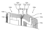
- FIG. 13 is a perspective view of the stator 10A according to the modified example 5.
- FIG. 14 is an enlarged view of two adjacent molded coils in the stator 10A according to the modified example 5.
- the first terminal portion 120a and the third terminal portion 120b are located on the outer portion of the stator 10. It may be arranged in.
- a concave portion or a hole is formed in the first engaging portion 122a of the first molded coil 100a, and a convex portion is formed in the second engaging portion 122b of the second molded coil 100b, but the present invention is not limited to this.
- a convex portion may be formed in the first engaging portion 122a of the first forming coil 100a, and a concave portion or a hole portion may be formed in the second engaging portion 122b of the second forming coil 100b.
- the number of slots in the stator 10 was 12, but it is not limited to this.
- the number of magnetic poles of the rotor 20 was 10 (that is, the number of permanent magnets 22 was 10), but the number is not limited to this. Any number can be applied to the number of slots of the stator 10 and the number of magnetic poles of the rotor 20.
- the rotor 20 was an IPM rotor, but it is not limited to this.
- a surface magnet type rotor SPM (Surface Permanent Magnetic) rotor) in which a plurality of permanent magnets are provided on the outer surface of the rotor core may be used.
- the motor 1 was illustrated as a rotary electric machine, but it is not limited to this.
- the rotary electric machine using the molded coil may be a generator.
- the technology disclosed in this disclosure can be widely used in various products using molded coils, including rotary electric machines such as electric motors.
Abstract
According to the present invention, a first molding coil that is one of two molding coils arranged adjacent to each other comprises: a first winding part in which conductors are stacked from a first turn to an nth turn (n is an integer of 2 or more); and a first terminal part that has a lead portion extending from a portion of the first turn of the first winding part in a direction perpendicular to the stacking direction of the conductors in the first winding part, wherein a first engagement part, which engages with a second engagement portion formed at a tip portion of a third terminal part of a second molding coil that is the other of the two molding coils, is formed at a tip portion of the first terminal part.
Description
本開示は、電動機を含む回転電機、回転電機に用いられるステータ、及びステータの巻線コイルとして用いられる成形コイルに関する。
The present disclosure relates to a rotary electric machine including an electric machine, a stator used in the rotary electric machine, and a molded coil used as a winding coil of the stator.
回転電機の一つとして、電気エネルギーを機械エネルギーに変える電動機が知られている。電動機は、家庭用機器又は産業用機器等の様々な製品に用いられている。例えば、電動機は、電気掃除機等の家電製品をはじめとして、自動車及びロボット等にも多種多様に用いられている。
As one of the rotary electric machines, an electric machine that converts electric energy into mechanical energy is known. Motors are used in various products such as household equipment or industrial equipment. For example, electric motors are widely used in automobiles, robots, and the like, as well as home appliances such as vacuum cleaners.
近年、電動機については、さらなる高効率化及び低コスト化が求められている。電動機の効率を向上させる手法として、電動機のステータに用いられる巻線コイルの占積率を高めることが提案されている。巻線コイルの占積率を高くすることで、電動機の駆動時に巻線コイルに流れる電流に起因する損失を抑制できる。したがって、電動機の効率を向上させることができる。
In recent years, there has been a demand for higher efficiency and lower cost for motors. As a method for improving the efficiency of the motor, it has been proposed to increase the space factor of the winding coil used for the stator of the motor. By increasing the space factor of the winding coil, it is possible to suppress the loss caused by the current flowing through the winding coil when the motor is driven. Therefore, the efficiency of the motor can be improved.
従来、電動機のステータに配置される巻線コイルの占積率を高める技術の一つとして、巻線コイルとしてエッジワイズコイル又は成形コイルを用いることが知られている。例えば、特許文献1には、ステータのスロット形状に適合するように成形された成形コイルを用いた電動機が開示されている。
Conventionally, it is known to use an edgewise coil or a molded coil as a winding coil as one of the techniques for increasing the space factor of the winding coil arranged in the stator of the motor. For example, Patent Document 1 discloses an electric motor using a molded coil molded to fit the slot shape of a stator.
電動機において、巻線コイルは、ステータのスロットに配置される。ステータのスロットに配置された複数の巻線コイルは、結線することで互いに電気的に接続される。この場合、丸線によって構成された丸線コイルは、巻線部から引き出した丸線を自由に引き回すことができるので、巻線コイルとして丸線コイルを用いたステータでは、スロットに配置された複数の丸線コイル同士を容易に結線することができる。
In the motor, the winding coil is arranged in the slot of the stator. A plurality of winding coils arranged in the slots of the stator are electrically connected to each other by being connected. In this case, since the round wire coil configured by the round wire can freely route the round wire drawn from the winding portion, in the stator using the round wire coil as the winding coil, a plurality of round wires arranged in the slot. The round wire coils can be easily connected to each other.
しかしながら、成形コイルは、丸線コイルとは異なり高い剛性を有する板状の導体によって構成されている。よって、巻線コイルとして成形コイルを用いたステータでは、丸線コイルを用いる場合と比べて、スロットに配置された複数の成形コイル同士を簡便に結線することができない。
However, unlike the round wire coil, the molded coil is composed of a plate-shaped conductor having high rigidity. Therefore, in the stator using the molded coil as the winding coil, it is not possible to easily connect the plurality of molded coils arranged in the slots to each other as compared with the case of using the round wire coil.
例えば、成形コイルとして、板枠状の導体が積層された巻線部と、巻線部の第1ターン(巻き始め)の部分から突出する第1端子部と、巻線部の最終ターン(巻き終わり)の部分から突出する第2端子部とを有するものが知られている。
For example, as a forming coil, a winding portion in which plate frame-shaped conductors are laminated, a first terminal portion protruding from the first turn (winding start) portion of the winding portion, and a final turn (winding) of the winding portion. Those having a second terminal portion protruding from the end) portion are known.
このような成形コイルをステータの複数のスロットの各々に配置すると、各成形コイルにおいて、第1端子部と第2端子部との位置がステータの半径方向で異なることになる。つまり、各成形コイルにおける第1端子部と第2端子部との位置は、ステータの中心から等距離の位置に存在していない。すなわち、第1端子部と第2端子部とは同じ円周上に位置していない。
When such a molded coil is arranged in each of the plurality of slots of the stator, the positions of the first terminal portion and the second terminal portion in each molded coil are different in the radial direction of the stator. That is, the positions of the first terminal portion and the second terminal portion in each molded coil do not exist at equidistant positions from the center of the stator. That is, the first terminal portion and the second terminal portion are not located on the same circumference.
このため、ステータのスロットに配置された同じ形状の2つの成形コイルを結線するには、バスバー等の連結部材を別途用いる必要がある。例えば、隣り合う2つの成形コイルにバスバーを橋架して、2つの成形コイルのうちの一方の成形コイルの第1端子部とバスバーの一方の端部とを接合し、2つの成形コイルのうちの他方の成形コイルの第2端子部とバスバーの他方の端部とを接合する。
Therefore, in order to connect two molded coils of the same shape arranged in the slot of the stator, it is necessary to separately use a connecting member such as a bus bar. For example, a bus bar is bridged between two adjacent molded coils, and the first terminal portion of one of the two molded coils and one end of the bus bar are joined to each other, and the two molded coils are joined. The second terminal portion of the other molded coil and the other end portion of the bus bar are joined.
しかしながら、このように2つの成形コイルをバスバーを用いて結線しようとすると、成形コイルとバスバーとを接合する際の治具又は設備を頻繁に動かす必要がある等して、結線作業が煩雑になる。
However, if it is attempted to connect the two forming coils using a bus bar in this way, the wiring work becomes complicated because it is necessary to frequently move the jig or equipment for joining the forming coil and the bus bar. ..
本開示は、このような問題を解決するためになされたものである。本開示は、バスバー等の連結部材を用いることなく簡便に2つの成形コイルの結線を行うことができる、成形コイル、その成型コイルを用いたステータ及びそのステータを用いた回転電機を提供することを目的とする。
This disclosure is made to solve such a problem. The present disclosure provides a molded coil, a stator using the molded coil, and a rotary electric machine using the stator, which can easily connect two molded coils without using a connecting member such as a bus bar. The purpose.
上記目的を達成するために、本開示に係る成形コイルの一態様は、隣り合って配置される2つの成形コイルのうちの一方の成形コイルであって、第1ターンから第nターン(nは2以上の整数)で導体が積層された巻線部と、前記巻線部の前記第1ターンから前記巻線部における前記導体の積層方向と直交する方向に延在するリード部を有する第1端子部と、前記巻線部の前記第nターンの部分から前記巻線部における前記導体の積層方向と直交する方向に延在するリード部を有する第2端子部と、を備え、前記第1端子部の先端部には、前記2つの成形コイルの他方の成形コイルの端子部の先端部に形成された第2係合部と係合する第1係合部が形成されている。
In order to achieve the above object, one aspect of the molded coil according to the present disclosure is one of two molded coils arranged adjacent to each other, from the first turn to the nth turn (n is). A first having a winding portion in which conductors are laminated with (2 or more integers) and a lead portion extending from the first turn of the winding portion in a direction orthogonal to the stacking direction of the conductors in the winding portion. The first terminal portion includes a terminal portion and a second terminal portion having a lead portion extending in a direction orthogonal to the stacking direction of the conductor in the winding portion from the nth turn portion of the winding portion. A first engaging portion that engages with a second engaging portion formed at the tip of the terminal portion of the other molded coil of the two molded coils is formed at the tip of the terminal portion.
また、本開示に係るステータの一態様は、複数のティースを有するコアと、各々が前記複数のティースに巻かれた複数の成形コイルと、を備え、前記複数の成形コイルは、第1成形コイルと、前記第1成形コイルに隣り合って配置される第2成形コイルとを含み、前記第1成形コイルは、第1ターンから第n1ターン(n1は2以上の整数)で第1導体が積層された第1巻線部と、前記第1巻線部の前記第1ターンの部分から前記第1巻線部における前記第1導体の積層方向と直交する方向に延在するリード部を有する第1端子部と、前記第1巻線部の前記第n1ターンの部分から前記第1巻線部における前記第1導体の積層方向と直交する方向に延在するリード部を有する第2端子部と、を有し、前記第2成形コイルは、第1ターンから第n2ターン(n2は2以上の整数)で第2導体が積層された第2巻線部と、前記第2巻線部の前記第1ターンの部分から前記第2巻線部における前記第2導体の積層方向と直交する方向に延在するリード部を有する第3端子部と、前記第2巻線部の前記第n2ターンの部分から前記第2巻線部における前記第2導体の積層方向と直交する方向に延在するリード部を有する第4端子部と、を有し、前記第1端子部の先端部には、第1係合部が形成されており、前記第3端子部の先端部には、前記第1係合部に係合する第2係合部が形成されており、前記第1端子部と前記第3端子部とは、前記第1係合部と前記第2係合部とが接合されることで連結されている。
Further, one aspect of the stator according to the present disclosure includes a core having a plurality of teeth and a plurality of molded coils each wound around the plurality of teeth, and the plurality of molded coils are the first molded coil. When the first and a second shaping coils disposed adjacent to the forming coil, wherein the first shaping coils, the n 1 turns from the first turn (n 1 is an integer of 2 or more) first conductor A lead portion extending in a direction orthogonal to the stacking direction of the first conductor in the first winding portion from the first turn portion of the first winding portion and the first winding portion in which the first winding portion is laminated. second having a first terminal portion, the lead portion extending in a direction perpendicular to the stacking direction of the first conductor from said portion of said n 1 turn of the first winding part of the first winding portion having has a terminal portion, said second forming coil has a second winding section first n 2 turns from the first turn (n 2 is an integer greater than or equal to 2) of the second conductor in stacked, the second A third terminal portion having a lead portion extending in a direction orthogonal to the stacking direction of the second conductor in the second winding portion from the first turn portion of the winding portion, and the second winding portion. anda fourth terminal portion having a lead portion extending in a direction perpendicular to the stacking direction of the second conductor in the second winding portion from a portion of the first n 2 turns, said first terminal portion A first engaging portion is formed at the tip portion, and a second engaging portion that engages with the first engaging portion is formed at the tip portion of the third terminal portion. The 1-terminal portion and the third terminal portion are connected by joining the first engaging portion and the second engaging portion.
また、本開示に係る回転電機の一態様は、上記のステータと、前記ステータの磁力により回転するロータと、を備える。
Further, one aspect of the rotary electric machine according to the present disclosure includes the above-mentioned stator and a rotor that rotates by the magnetic force of the stator.
本開示によれば、バスバー等の連結部材を用いることなく簡便に2つの成形コイルの結線を行うことができる。
According to the present disclosure, it is possible to easily connect two molded coils without using a connecting member such as a bus bar.
以下、本開示の実施の形態について説明する。なお、以下に説明する実施の形態は、いずれも本開示の一具体例を示すものである。したがって、以下の実施の形態で示される、数値、構成要素、構成要素の配置位置及び接続形態、並びに、工程及び工程の順序等は、一例であって本開示を限定する主旨ではない。よって、以下の実施の形態における構成要素のうち、本開示の最上位概念を示す独立請求項に記載されていない構成要素については、任意の構成要素として説明される。
Hereinafter, embodiments of the present disclosure will be described. It should be noted that all of the embodiments described below show a specific example of the present disclosure. Therefore, the numerical values, the components, the arrangement positions and connection forms of the components, the steps, the order of the steps, and the like shown in the following embodiments are examples and do not limit the present disclosure. Therefore, among the components in the following embodiments, the components not described in the independent claims indicating the highest level concept of the present disclosure are described as arbitrary components.
各図は、模式図であり、必ずしも厳密に図示されたものではない。なお、各図において、実質的に同一の構成に対しては同一の符号を付しており、重複する説明は省略又は簡略化する。
Each figure is a schematic diagram and is not necessarily exactly illustrated. In each figure, the same reference numerals are given to substantially the same configurations, and duplicate explanations will be omitted or simplified.
本実施の形態において、ステータ10及びロータ20の半径方向を「径方向」とし、ロータ20の回転方向を「周方向」とする。つまり、回転軸23の軸心Cを中心として軸心Cから広がる方向が「径方向」であり、回転軸23の軸心Cを中心として軸心Cを周回する方向が「周方向」である。したがって、「径方向」は、回転軸23の軸心Cの方向と直交する方向となる。なお、本明細書において、「上」及び「下」という用語は、必ずしも、絶対的な空間認識における上方向(鉛直上方)及び下方向(鉛直下方)を指すものではない。
In the present embodiment, the radial direction of the stator 10 and the rotor 20 is the "radial direction", and the rotation direction of the rotor 20 is the "circumferential direction". That is, the direction extending from the axis C around the axis C of the rotating shaft 23 is the "diameter direction", and the direction rotating around the axis C around the axis C of the rotating shaft 23 is the "circumferential direction". .. Therefore, the "diametrical direction" is a direction orthogonal to the direction of the axis C of the rotating shaft 23. In the present specification, the terms "upper" and "lower" do not necessarily refer to the upward direction (vertically upward) and the downward direction (vertically downward) in absolute spatial recognition.
(実施の形態)
以下の実施の形態では、回転電機の一例として電動機について説明する。 (Embodiment)
In the following embodiment, an electric machine will be described as an example of a rotary electric machine.
以下の実施の形態では、回転電機の一例として電動機について説明する。 (Embodiment)
In the following embodiment, an electric machine will be described as an example of a rotary electric machine.
まず、実施の形態に係る電動機1の全体の構成について、図1及び図2を用いて説明する。図1は、実施の形態に係る電動機1の断面図である。また、図2は、同電動機1におけるステータ10の斜視図である。なお、図1は、ロータ20が有する回転軸23の軸心Cの方向と直交する平面で切断したときの断面を示している。
First, the overall configuration of the motor 1 according to the embodiment will be described with reference to FIGS. 1 and 2. FIG. 1 is a cross-sectional view of the electric motor 1 according to the embodiment. Further, FIG. 2 is a perspective view of the stator 10 in the motor 1. Note that FIG. 1 shows a cross section when cut in a plane orthogonal to the direction of the axis C of the rotating shaft 23 of the rotor 20.
図1に示すように、電動機1は、ステータ10とロータ20とを備える。ステータ10とロータ20とは対向して配置される。電動機1は、ロータ20がステータ10の内側に配置されたインナーロータ型のモータである。なお、電動機1は、ステータ10及びロータ20以外に、モータケース及び回転軸23を軸支する軸受等の部品も有しているが、便宜上、その部品の図示及び説明は省略する。
As shown in FIG. 1, the motor 1 includes a stator 10 and a rotor 20. The stator 10 and the rotor 20 are arranged so as to face each other. The electric motor 1 is an inner rotor type motor in which the rotor 20 is arranged inside the stator 10. In addition to the stator 10 and the rotor 20, the motor 1 also has parts such as a bearing that supports the motor case and the rotating shaft 23, but for convenience, the illustration and description of the parts will be omitted.
ステータ10(固定子)は、ロータ20との間にエアギャップを介してロータ20に対向して配置されている。ロータ20の表面とステータ10の表面との間には微小なエアギャップが存在する。本実施の形態において、ステータ10は、ロータ20のロータコア21を囲むように配置されている。
The stator 10 (stator) is arranged between the stator and the rotor 20 so as to face the rotor 20 via an air gap. There is a small air gap between the surface of the rotor 20 and the surface of the stator 10. In the present embodiment, the stator 10 is arranged so as to surround the rotor core 21 of the rotor 20.
ステータ10は、ロータ20に作用する磁力を発生させる。具体的には、ステータ10は、ロータ20が有するロータコア21とのエアギャップ面に磁束を生成するように構成されている。例えば、ステータ10は、ロータコア21とのエアギャップに面する側の面にN極とS極とが周方向に交互に繰り返して生成されるように構成されている。
The stator 10 generates a magnetic force acting on the rotor 20. Specifically, the stator 10 is configured to generate a magnetic flux on the air gap surface of the rotor 20 with the rotor core 21. For example, the stator 10 is configured such that N poles and S poles are alternately and repeatedly generated in the circumferential direction on the surface facing the air gap with the rotor core 21.
図1及び図2に示すように、ステータ10は、成形コイル100と、ステータコア200とを有する。
As shown in FIGS. 1 and 2, the stator 10 has a molded coil 100 and a stator core 200.
成形コイル100は、巻線コイルとしてステータ10に設けられたステータコイルである。成形コイル100は、ステータ10の電機子巻線であり、ステータコア200に巻き回されている。具体的には、成形コイル100は、ステータ10の複数のティース210の各々に巻き回されている。したがって、ステータ10には、複数の成形コイル100が用いられている。複数の成形コイル100は、それぞれ複数のティース210に巻かれた構成になっている。
The molded coil 100 is a stator coil provided on the stator 10 as a winding coil. The forming coil 100 is an armature winding of the stator 10, and is wound around the stator core 200. Specifically, the forming coil 100 is wound around each of the plurality of teeth 210 of the stator 10. Therefore, a plurality of molded coils 100 are used for the stator 10. The plurality of molded coils 100 are each wound around a plurality of teeth 210.
複数の成形コイル100は、ロータ20を囲むように周方向に沿って等間隔に配置されている。各成形コイル100は、ステータ10のスロット230に収納されている。成形コイル100は、インシュレータ又は絶縁紙等の絶縁部材(不図示)を介してティース210に巻き回されてもよい。この場合、成形コイル100は、例えば、ティース210に装着されたインシュレータに巻き回された構成になる。
The plurality of molded coils 100 are arranged at equal intervals along the circumferential direction so as to surround the rotor 20. Each molded coil 100 is housed in the slot 230 of the stator 10. The forming coil 100 may be wound around the teeth 210 via an insulating member (not shown) such as an insulator or insulating paper. In this case, the forming coil 100 is wound around an insulator mounted on the teeth 210, for example.
成形コイル100は、丸線を用いた丸線コイルとは異なり、板状の導体を積層することで構成されている。成形コイル100は、丸線コイルと比べて高い占積率を有している。例えば、成形コイル100の占積率は、90%以上である。
The molded coil 100 is configured by laminating plate-shaped conductors, unlike a round wire coil using a round wire. The molded coil 100 has a higher space factor than the round wire coil. For example, the space factor of the molded coil 100 is 90% or more.
成形コイル100は、例えば、長さ、幅及び厚みが異なる複数の長方形の板材を準備し、これらの板材をプレスしたり、冷間圧接、溶接又はその他の方法で接合したりすることで形成することができる。板材としては、例えば、銅又はアルミニウム等の低抵抗の金属材料からなる金属板を用いることができる。
The forming coil 100 is formed, for example, by preparing a plurality of rectangular plates having different lengths, widths, and thicknesses, pressing the plates, and joining them by cold pressure welding, welding, or other methods. be able to. As the plate material, for example, a metal plate made of a low resistance metal material such as copper or aluminum can be used.
あるいは、成形コイル100は、銅等の金属材料を溶融して鋳型に流し込む、いわゆる鋳造によって形成されていてもよい。また、幅又は厚さを予め途中で異なるように形成した板状の導線を所定の位置で曲げ加工することで形成されていてもよい。また、幅及び厚さが一定の板状の導線を所定の部位で圧延加工して、途中で幅又は厚さを変更した後に螺旋状に巻回して形成されていてもよい。つまり、導線を巻回する以外にさらに別の加工を加えるか、あるいは、単に巻き回すのとは異なる工法を用いることで成形コイル100を形成することができる。
Alternatively, the molded coil 100 may be formed by so-called casting, in which a metal material such as copper is melted and poured into a mold. Further, it may be formed by bending a plate-shaped conducting wire having a width or a thickness different in the middle at a predetermined position. Further, a plate-shaped conductor having a constant width and thickness may be rolled at a predetermined portion, the width or thickness may be changed in the middle, and then the conductor may be spirally wound. That is, the forming coil 100 can be formed by adding another process other than winding the conductor, or by using a method different from simply winding the lead wire.
なお、成形コイル100の形状及び成形コイル100同士の接合構造については後述する。
The shape of the forming coil 100 and the joining structure between the forming coils 100 will be described later.
ステータコア200は、ステータ10のコアとなる鉄心である。本実施の形態において、ステータコア200は、複数のティース210と、円環状のヨーク220とによって構成されている。
The stator core 200 is an iron core that is the core of the stator 10. In the present embodiment, the stator core 200 is composed of a plurality of teeth 210 and an annular yoke 220.
複数のティース210の各々は、ロータ20の回転軸23の軸心Cに向かって突出している。具体的には、複数のティース210は、回転軸23の軸心Cと直交する方向(径方向)に放射状に設けられている。
Each of the plurality of teeth 210 projects toward the axis C of the rotating shaft 23 of the rotor 20. Specifically, the plurality of teeth 210 are provided radially in a direction (diametrical direction) orthogonal to the axis C of the rotating shaft 23.
隣り合う2つのティース210の間には、成形コイル100を配置するためのスロット230が形成されている。つまり、ステータ10のスロット230は、隣り合う2つのティース210の間に対応している。複数のティース210は、隣り合う2つのティース210の間にスロット230を形成しながら周方向に沿って等間隔に配置されている。本実施の形態において、ステータ10は12個のティース210を有しているので、ステータ10のスロット数は、12である。したがって、12個の成形コイル100が用いられている。
A slot 230 for arranging the forming coil 100 is formed between two adjacent teeth 210. That is, the slot 230 of the stator 10 corresponds between two adjacent teeth 210. The plurality of teeth 210 are arranged at equal intervals along the circumferential direction while forming slots 230 between two adjacent teeth 210. In the present embodiment, since the stator 10 has 12 teeth 210, the number of slots of the stator 10 is 12. Therefore, 12 molding coils 100 are used.
本実施の形態において、各ティース210は、円環状のヨーク220から径方向の内側に突出するように延在している。つまり、ヨーク220は、各ティース210の外側に形成されたバックヨークである。各ティース210は、ヨーク220に嵌合されて固定されている。
In the present embodiment, each tooth 210 extends radially inward from the annular yoke 220. That is, the yoke 220 is a back yoke formed on the outside of each tooth 210. Each tooth 210 is fitted and fixed to the yoke 220.
ティース210及びヨーク220の各々は、複数枚の電磁鋼板を積層することによって構成された積層体である。複数枚の電磁鋼板の各々は、例えば、所定形状に形成された打ち抜き鋼板である。ティース210とヨーク220は、別体であるが、1つのステータコア200として一体であってもよい。ティース210及びヨーク220が一体である場合も、ステータコア200は、複数枚の電磁鋼板を積層することによって構成された積層体である。なお、ティース210及びヨーク220は、別体の場合であっても一体の場合であっても、複数の電磁鋼板の積層体に限るものではなく、磁性材料によって構成されたバルク体であってもよい。
Each of the teeth 210 and the yoke 220 is a laminated body formed by laminating a plurality of electromagnetic steel sheets. Each of the plurality of electromagnetic steel sheets is, for example, a punched steel sheet formed into a predetermined shape. Although the teeth 210 and the yoke 220 are separate bodies, they may be integrated as one stator core 200. Even when the teeth 210 and the yoke 220 are integrated, the stator core 200 is a laminated body formed by laminating a plurality of electromagnetic steel sheets. The teeth 210 and the yoke 220 are not limited to a laminated body of a plurality of electrical steel sheets, whether they are separate bodies or integrally, and may be a bulk body made of a magnetic material. good.
複数のティース210は、磁極ティースであり、成形コイル100の通電により磁力を発生させる。ステータ10における複数の成形コイル100は、3相同期モータとしてロータ20が回転するように3相巻線として電気的に接続されている。具体的には、複数の成形コイル100は、互いに電気的に120度位相が異なる、U相、V相及びW相の3相それぞれの単位コイルによって構成されている。つまり、各ティース210に装着された成形コイル100は、U相、V相及びW相の相単位でそれぞれに通電される3相の交流によって通電駆動される。これにより、各ティース210にはステータ10の主磁束が生成される。
The plurality of teeth 210 are magnetic pole teeth, and a magnetic force is generated by energization of the forming coil 100. The plurality of forming coils 100 in the stator 10 are electrically connected as a three-phase winding so that the rotor 20 rotates as a three-phase synchronous motor. Specifically, the plurality of molded coils 100 are composed of unit coils of each of the three phases of U phase, V phase and W phase, which are electrically different in phase by 120 degrees from each other. That is, the molded coil 100 mounted on each tooth 210 is energized and driven by a three-phase alternating current that is energized in units of U phase, V phase, and W phase. As a result, the main magnetic flux of the stator 10 is generated in each tooth 210.
本実施の形態では、上記のように、12個の成形コイル100が用いられている。この場合、12個の成形コイル100は、図1に示すように、各成形コイル100に流れる電流の位相に応じて、4つのU相コイルU1~U4と、4つのV相コイルV1~V4と、4つのW相コイルW1~W4とに区分されて所定のスロット230に配置されている。4つのU相コイルU1~U4は、直列に接続される。同様に、4つのV相コイルV1~V4は、直列に接続されている。4つのW相コイルW1~W4も、直列に接続されている。
In this embodiment, as described above, 12 molded coils 100 are used. In this case, as shown in FIG. 1, the 12 forming coils 100 have four U-phase coils U1 to U4 and four V-phase coils V1 to V4 according to the phase of the current flowing through each forming coil 100. It is divided into four W-phase coils W1 to W4 and arranged in a predetermined slot 230. The four U-phase coils U1 to U4 are connected in series. Similarly, the four V-phase coils V1 to V4 are connected in series. The four W-phase coils W1 to W4 are also connected in series.
ロータ20(回転子)は、ステータ10の磁力により回転する。ロータ20も磁力を生成する。具体的には、ロータ20は、周方向に亘って磁束を生成するN極とS極とが複数交互に繰り返して存在する構成になっている。これにより、ロータ20は、ステータ10に作用する磁力を発生する。本実施の形態において、ロータ20から発生する磁束の向きは、回転軸23の軸心Cの方向(軸心方向)と直交する方向である。つまり、ロータ20が発生する磁束の向きは、ラジアル方向(径方向)である。
The rotor 20 (rotor) is rotated by the magnetic force of the stator 10. The rotor 20 also generates a magnetic force. Specifically, the rotor 20 has a configuration in which a plurality of N poles and S poles that generate magnetic flux in the circumferential direction are alternately and repeatedly present. As a result, the rotor 20 generates a magnetic force acting on the stator 10. In the present embodiment, the direction of the magnetic flux generated from the rotor 20 is a direction orthogonal to the direction of the axis C of the rotating shaft 23 (direction of the axis). That is, the direction of the magnetic flux generated by the rotor 20 is the radial direction (diameter direction).
ロータ20は、ロータコア21と、複数の永久磁石22と、回転軸23とを有する。ロータ20は、回転軸23の軸心Cを回転中心として回転する。つまり、回転軸23は、ロータ20が回転する際の中心軸となる。
The rotor 20 has a rotor core 21, a plurality of permanent magnets 22, and a rotating shaft 23. The rotor 20 rotates about the axis C of the rotating shaft 23 as the center of rotation. That is, the rotation shaft 23 becomes the central axis when the rotor 20 rotates.
本実施の形態において、ロータ20は、永久磁石22がロータコア21に埋め込まれた永久磁石埋め込み型のロータ(IPM(Interior Permanent Magnet)ロータ)である。したがって、本実施の形態における電動機1は、IPMモータである。
In the present embodiment, the rotor 20 is a permanent magnet embedded rotor (IPM (Interior Permanent Magnet) rotor) in which the permanent magnet 22 is embedded in the rotor core 21. Therefore, the electric motor 1 in the present embodiment is an IPM motor.
ロータコア21は、ロータ20のコアとなる鉄心である。ロータコア21は、複数の電磁鋼板が回転軸23の軸心Cの方向(軸心方向)に積層された積層体である。複数の電磁鋼板の各々は、例えば、所定形状に形成された打ち抜き鋼板である。複数の電磁鋼板は、例えばかしめによって互いに固定されている。ロータコア21は、複数の電磁鋼板の積層体に限らず、磁性材料によって構成されたバルク体であってもよい。
The rotor core 21 is an iron core that is the core of the rotor 20. The rotor core 21 is a laminated body in which a plurality of electrical steel sheets are laminated in the direction of the axial center C of the rotating shaft 23 (axial center direction). Each of the plurality of electromagnetic steel sheets is, for example, a punched steel sheet formed into a predetermined shape. A plurality of electrical steel sheets are fixed to each other by, for example, caulking. The rotor core 21 is not limited to a laminated body of a plurality of electromagnetic steel sheets, but may be a bulk body made of a magnetic material.
永久磁石22は、ロータコア21に設けられた磁石挿入孔に配置されている。本実施の形態では、ロータコア21には10個の磁石挿入孔が設けられている。各磁石挿入孔に板状の永久磁石22が挿入されている。一例として、永久磁石22は、焼結マグネットである。なお、永久磁石22は、ボンド磁石であってもよい。
The permanent magnet 22 is arranged in the magnet insertion hole provided in the rotor core 21. In this embodiment, the rotor core 21 is provided with 10 magnet insertion holes. A plate-shaped permanent magnet 22 is inserted into each magnet insertion hole. As an example, the permanent magnet 22 is a sintered magnet. The permanent magnet 22 may be a bond magnet.
回転軸23は、長尺状のシャフトであり、例えば金属棒である。回転軸23は、ロータコア21に固定されている。具体的には、回転軸23は、軸心Cの方向においてロータコア21の両側に延在するように、ロータコア21の中心に設けられた貫通孔に挿入されてロータコア21に固定されている。回転軸23は、例えばロータコア21の貫通孔に圧入したり焼き嵌めしたりすることでロータコア21に固定されている。電動機1において、回転軸23のロータコア21から突出した部分の一方は、出力軸として機能する。例えば、回転軸23には回転ファン等の負荷が取り付けられる。なお、図示しないが、回転軸23は、ベアリング等の軸受によって回転自在に支持されている。
The rotating shaft 23 is a long shaft, for example, a metal rod. The rotating shaft 23 is fixed to the rotor core 21. Specifically, the rotating shaft 23 is inserted into a through hole provided in the center of the rotor core 21 and fixed to the rotor core 21 so as to extend on both sides of the rotor core 21 in the direction of the axis C. The rotary shaft 23 is fixed to the rotor core 21 by, for example, press-fitting or shrink-fitting into the through hole of the rotor core 21. In the motor 1, one of the portions of the rotating shaft 23 protruding from the rotor core 21 functions as an output shaft. For example, a load such as a rotating fan is attached to the rotating shaft 23. Although not shown, the rotary shaft 23 is rotatably supported by a bearing such as a bearing.
このように構成される電動機1では、ステータ10が有する成形コイル100に通電すると、界磁電流が成形コイル100に流れてステータ10に磁界が生成される。これにより、ステータ10からロータ20に向かう磁束が生成される。具体的には、ステータ10が有するステータコア200のティース210の各々からロータ20に向かう磁束が生成される。一方、ロータ20では、ロータコア21に配置された永久磁石22によってステータ10を通る磁束が生成される。このステータ10で生成される磁束とロータ20が有する永久磁石22から生じる磁束との相互作用によって生じた磁気力がロータ20を回転させるトルクとなり、ロータ20が回転する。
In the motor 1 configured in this way, when the forming coil 100 of the stator 10 is energized, a field current flows through the forming coil 100 and a magnetic field is generated in the stator 10. As a result, a magnetic flux from the stator 10 to the rotor 20 is generated. Specifically, a magnetic flux is generated from each of the teeth 210 of the stator core 200 of the stator 10 toward the rotor 20. On the other hand, in the rotor 20, a magnetic flux passing through the stator 10 is generated by the permanent magnets 22 arranged in the rotor core 21. The magnetic force generated by the interaction between the magnetic flux generated by the stator 10 and the magnetic flux generated by the permanent magnet 22 of the rotor 20 becomes the torque for rotating the rotor 20, and the rotor 20 rotates.
次に、本実施の形態に係る電動機1に用いられる成形コイル100の詳細な構成について、図1及び図2を参照しつつ、図3A、図3B及び図4を用いて説明する。図3Aは、実施の形態に係る電動機1のステータ10における隣り合う2つの成形コイル100の拡大図である。図3Bは、同ステータ10における隣り合う2つの成形コイル100の上面図である。図4は、同ステータ10における隣り合う2つの成形コイル100の連結するときの様子を示す図である。
Next, the detailed configuration of the molded coil 100 used in the motor 1 according to the present embodiment will be described with reference to FIGS. 1 and 2 with reference to FIGS. 3A, 3B and 4. FIG. 3A is an enlarged view of two adjacent molded coils 100 in the stator 10 of the motor 1 according to the embodiment. FIG. 3B is a top view of two adjacent molded coils 100 in the stator 10. FIG. 4 is a diagram showing a state when two adjacent forming coils 100 in the same stator 10 are connected.
上述のように、成形コイル100として図1及び図2に示される4つのU相コイルU1~U4は、直列に接続される。U相コイルU1とU相コイルU2との2つの成形コイル100が隣り合って配置される。また、U相コイルU3とU相コイルU4との2つの成形コイル100が隣り合って配置される。
As described above, the four U-phase coils U1 to U4 shown in FIGS. 1 and 2 as the forming coil 100 are connected in series. Two molded coils 100 of the U-phase coil U1 and the U-phase coil U2 are arranged next to each other. Further, two molded coils 100 of the U-phase coil U3 and the U-phase coil U4 are arranged next to each other.
同様に、V相コイルV1とV相コイルV2との2つの成形コイル100が隣り合って配置される。V相コイルV3とV相コイルV4との2つの成形コイル100が隣り合って配置される。W相コイルW1とW相コイルW2との2つの成形コイル100が隣り合って配置される。W相コイルW3とW相コイルW4との2つの成形コイル100が隣り合って配置される。
Similarly, two molded coils 100 of the V-phase coil V1 and the V-phase coil V2 are arranged next to each other. Two molded coils 100 of the V-phase coil V3 and the V-phase coil V4 are arranged next to each other. Two molded coils 100, a W-phase coil W1 and a W-phase coil W2, are arranged next to each other. Two molded coils 100 of the W-phase coil W3 and the W-phase coil W4 are arranged next to each other.
これらの成形コイル100において、隣り合って配置される2つの成形コイル100のうちの一方を第1成形コイル100aとし、他方を第2成形コイル100bとすると、第1成形コイル100aと第2成形コイル100bとはバスバー等の連結部材を介することなく直接接続されている。
In these forming coils 100, if one of the two forming coils 100 arranged adjacent to each other is the first forming coil 100a and the other is the second forming coil 100b, the first forming coil 100a and the second forming coil are used. It is directly connected to 100b without a connecting member such as a bus bar.
以下、成形コイル100の構成を詳細に説明するとともに、隣り合って配置される2つの成形コイル100の接合部分の構造について詳細に説明する。具体的には、隣り合って配置される2つの成形コイル100の複数組みのうち、U相コイルU1である成形コイル100を第1成形コイル100aとし、U相コイルU2である成形コイル100を第2成形コイル100bとして、U相コイルU1とU相コイルU2とを接合する場合を例にとって説明する。
Hereinafter, the configuration of the molded coil 100 will be described in detail, and the structure of the joint portion of the two molded coils 100 arranged adjacent to each other will be described in detail. Specifically, among the plurality of sets of the two molded coils 100 arranged adjacent to each other, the molded coil 100 which is the U-phase coil U1 is designated as the first molded coil 100a, and the molded coil 100 which is the U-phase coil U2 is the first. A case where the U-phase coil U1 and the U-phase coil U2 are joined as the two forming coil 100b will be described as an example.
第1成形コイル100a及び第2成形コイル100bは、絶縁被膜された板状の導体によって構成されている。第1成形コイル100aを構成する板状の第1導体及び第2成形コイル100bを構成する板状の第2導体は、いずれも、断面形状が四角形で、素材が銅である。
The first molded coil 100a and the second molded coil 100b are composed of a plate-shaped conductor coated with an insulating coating. The plate-shaped first conductor constituting the first forming coil 100a and the plate-shaped second conductor constituting the second forming coil 100b both have a quadrangular cross-sectional shape and are made of copper.
図2、図3A及び図3Bに示すように、第1成形コイル100aは、第1巻線部110aと、第1巻線部110aから上方向に突出する第1端子部120a及び第2端子部130aとを有する。
As shown in FIGS. 2, 3A and 3B, the first forming coil 100a includes a first winding portion 110a, a first terminal portion 120a and a second terminal portion protruding upward from the first winding portion 110a. It has 130a and.
第1巻線部110aは、巻き始めを第1ターンとし、巻き終わりを第n1ターン(n1は2以上の整数)とすると、第1ターンから第n1ターンまで導体が積層された構成になっている。つまり、第1巻線部110aは、n1ターンのコイルを構成する積層された導体を有する。第1巻線部110aは、平板状の導体が厚み方向に螺旋状に巻回するように積層されている。
First winding unit 110a, the winding start and the first turn, the winding end first n 1 turn (n 1 is an integer of 2 or more) When the conductor from the first turn to the n 1 turns are stacked configuration It has become. That is, the first winding portion 110a has laminated conductors constituting the coil of n 1 turn. The first winding portion 110a is laminated so that a flat plate-shaped conductor is spirally wound in the thickness direction.
具体的には、第1巻線部110aにおける導体の積層方向から見たときに、第1巻線部110aの形状は、実質的に矩形の枠状になっている。つまり、第1ターンから第n1ターンまでのn回巻きの平板状の導体からなる第1巻線部110aは、ステータ10の径方向から見て4つの辺部を有する実質的に矩形の環状に形成されている。
Specifically, when viewed from the stacking direction of the conductors in the first winding portion 110a, the shape of the first winding portion 110a is substantially a rectangular frame shape. That is, the first winding portion 110a made of n turns of a flat conductor of the first turn to the n 1 turn, substantially rectangular annular with four sides as viewed from the radial direction of the stator 10 Is formed in.
本実施の形態において、第1巻線部110aは、第1ターンの部分がステータ10の内側部分で、第n1ターンの部分がステータ10の外側部分に位置するように配置されている。つまり、第1巻線部110aは、第1ターンの部分から第n1ターンの部分までが回転軸23の軸心Cから径方向外側に向かってこの順で積層されている。第1巻線部110aは、スロット230内に収納されている。第1巻線部110aの外形は、スロット230に適合した形状になっている。
In the present embodiment, the first winding portion 110a is arranged so that the portion of the first turn is located at the inner portion of the stator 10 and the portion of the nth turn is located at the outer portion of the stator 10. That is, the first winding portion 110a is laminated in this order from the portion of the first turn to the portion of the nth turn 1 from the axial center C of the rotating shaft 23 toward the outer side in the radial direction. The first winding portion 110a is housed in the slot 230. The outer shape of the first winding portion 110a has a shape suitable for the slot 230.
第1巻線部110aを構成する板状の導体は、表面全体が絶縁被膜されているので、ターン間の界面は絶縁されている。したがって、第1巻線部110aに供給された電流は、第1ターンから第n1ターンまで又は第n1ターンから第1ターンまで螺旋状に流れることになる。
Since the entire surface of the plate-shaped conductor constituting the first winding portion 110a is coated with an insulating film, the interface between turns is insulated. Accordingly, the current supplied to the first winding unit 110a will flow spirally from the first turn or from the n 1 turn to first turn to the n 1 turn.
第1端子部120a及び第2端子部130aは、第1成形コイル100aを第1成形コイル100a以外の他の成形コイル100と電気的に接続するための結線部として機能する。本実施の形態において、第1端子部120aは、U相コイルU2である第2成形コイル100bに結線され、第2端子部130aは、U相コイルU3又はU相コイルU4に結線される。
The first terminal portion 120a and the second terminal portion 130a function as a wiring portion for electrically connecting the first forming coil 100a to other forming coils 100 other than the first forming coil 100a. In the present embodiment, the first terminal portion 120a is connected to the second forming coil 100b, which is the U-phase coil U2, and the second terminal portion 130a is connected to the U-phase coil U3 or the U-phase coil U4.
第1端子部120aは、第1巻線部110aの第1ターンから導体が延在する部分である。第1成形コイル100aは、第1ターンの部分の第1巻線部110aの一部として第2成形コイル100bに向かって延在する延在部112を有しており、第1端子部120aは、延在部112から延在している。具体的には、延在部112は、第1巻線部110aのコイルエンド111aの一部として第2成形コイル100bにおける第2巻線部110bのコイルエンド111bに向かって延在している。また、第1端子部120aは、延在部112の第2成形コイル100b側の端部から上方に向かって突出している。
The first terminal portion 120a is a portion where the conductor extends from the first turn of the first winding portion 110a. The first forming coil 100a has an extending portion 112 extending toward the second forming coil 100b as a part of the first winding portion 110a of the portion of the first turn, and the first terminal portion 120a has an extending portion 112. , It extends from the extension portion 112. Specifically, the extending portion 112 extends toward the coil end 111b of the second winding portion 110b in the second forming coil 100b as a part of the coil end 111a of the first winding portion 110a. Further, the first terminal portion 120a projects upward from the end portion of the extending portion 112 on the second forming coil 100b side.
第1巻線部110aから突出する第1端子部120aは、リード部121aと、第1係合部122aとを有する。
The first terminal portion 120a protruding from the first winding portion 110a has a lead portion 121a and a first engaging portion 122a.
リード部121aは、第1巻線部110aの第1ターンの部分から第1巻線部110aにおける導体の積層方向と直交する方向に延在する部分である。本実施の形態において、リード部121aは、延在部112の第2成形コイル100b側の端部から上方に向かって直線状に延在している。
The lead portion 121a is a portion extending from the portion of the first turn of the first winding portion 110a in the direction orthogonal to the stacking direction of the conductors in the first winding portion 110a. In the present embodiment, the lead portion 121a extends linearly upward from the end portion of the extending portion 112 on the second forming coil 100b side.
第1係合部122aは、第2成形コイル100bの第2係合部122bと嵌り合う形状を有する。図3A、図3B及び図4に示すように、第1係合部122aは、第2係合部122bと嵌合する凹部を有する。また、第1係合部122aは、第1端子部120aの先端部に形成されている。具体的には、第1係合部122aは、リード部121aの先端部に形成されている。
The first engaging portion 122a has a shape that fits with the second engaging portion 122b of the second forming coil 100b. As shown in FIGS. 3A, 3B and 4, the first engaging portion 122a has a recess that fits into the second engaging portion 122b. Further, the first engaging portion 122a is formed at the tip end portion of the first terminal portion 120a. Specifically, the first engaging portion 122a is formed at the tip end portion of the lead portion 121a.
第2端子部130aは、第1端子部120aと同様に、第1巻線部110aから導体が延在する部分である。第2端子部130aは、第1巻線部110aの第n1ターンから導体が延在する部分である。具体的には、第2端子部130aは、第1巻線部110aの第n1ターンの部分から第1巻線部110aにおける導体の積層方向と直交する方向に延在するリード部を有する。なお、第2端子部130aは、第1端子部120aと同じ方向に延在している。
The second terminal portion 130a is a portion where the conductor extends from the first winding portion 110a, similarly to the first terminal portion 120a. The second terminal portion 130a is a portion where the conductive from the n 1 turn of the first winding portion 110a extends. Specifically, the second terminal portion 130a has a lead portion extending in a direction perpendicular to the stacking direction of the conductor at the portion of the n 1 turn of the first winding unit 110a first winding unit 110a. The second terminal portion 130a extends in the same direction as the first terminal portion 120a.
次に、第2成形コイル100bについて説明する。図2、図3A、及び図3Bに示すように、第2成形コイル100bは、第2巻線部110bと、第2巻線部110bから上方向に突出する第3端子部120b及び第4端子部130bとを有する。
Next, the second forming coil 100b will be described. As shown in FIGS. 2, 3A, and 3B, the second forming coil 100b has a second winding portion 110b, a third terminal portion 120b and a fourth terminal protruding upward from the second winding portion 110b. It has a portion 130b.
第2巻線部110bは、巻き始めを第1ターンとし、巻き終わりを第n2ターン(n2は2以上の整数)とすると、第1成形コイル100aの第1巻線部110aと同様に、第1ターンから第n2ターンまで導体が積層された構成になっている。つまり、第2巻線部110bは、n2ターンのコイルを構成する積層された導体を有する。第1巻線部110aと同様に、第2巻線部110bは、平板状の導体が厚み方向に螺旋状に巻回するように積層されている。
Second winding unit 110b, a winding start first and turn the winding end when the n 2 turns (n 2 is an integer of 2 or more) that, similarly to the first winding portion 110a of the first molded coil 100a has a structure in which the conductor is laminated from the first turn to the n 2 turns. That is, the second coil portion 110b has a stacked conductors constituting the n 2 turns of the coil. Similar to the first winding portion 110a, the second winding portion 110b is laminated so that a flat plate-shaped conductor is spirally wound in the thickness direction.
具体的には、第2巻線部110bにおける導体の積層方向から見たときに、第2巻線部110bの形状は、実質的に矩形の枠状になっている。つまり、第1ターンから第n2ターンまでのn回巻きの平板状の導体からなる第2巻線部110bは、ステータ10の径方向から見て4つの辺部を有する実質的に矩形の環状に形成されている。
Specifically, when viewed from the stacking direction of the conductors in the second winding portion 110b, the shape of the second winding portion 110b is substantially a rectangular frame shape. That is, the second coil portion 110b made of n turns of a flat conductor of the first turn to the n 2 turns, substantially rectangular annular with four sides as viewed from the radial direction of the stator 10 Is formed in.
第2巻線部110bの枠状の大きさは、第1巻線部110aの枠状の大きさと同じである。第2巻線部110bの巻き数は、第1巻線部110aの巻き数と同じである。つまり、n1=n2=nである。第2巻線部110bの枠状の大きさと第1巻線部110aの枠状の大きさとは異なっていてもよい。第2巻線部110bの巻き数と第1巻線部110aの巻き数とが異なっていてもよい。
The frame-shaped size of the second winding portion 110b is the same as the frame-shaped size of the first winding portion 110a. The number of turns of the second winding portion 110b is the same as the number of turns of the first winding portion 110a. That is, n 1 = n 2 = n. The frame-shaped size of the second winding portion 110b and the frame-shaped size of the first winding portion 110a may be different. The number of turns of the second winding portion 110b and the number of turns of the first winding portion 110a may be different.
第2巻線部110bは、第1ターンの部分がステータ10の内側部分で、第n2ターンの部分がステータ10の外側部分に位置するように配置されている。つまり、第2巻線部110bは、第1ターンの部分から第n2ターンの部分までが回転軸23の軸心Cから径方向外側に向かってこの順で積層されている。第2巻線部110bは、スロット230内に収納されている。第2巻線部110bの外形は、スロット230に適合した形状になっている。
The second winding portion 110b, the part of the first turn in the inner portion of the stator 10, part of the n 2 turns are arranged so as to be located on the outside portion of the stator 10. That is, the second winding portion 110b is laminated in this order from the portion of the first turn to the portion of the nth turn 2 from the axial center C of the rotating shaft 23 toward the outer side in the radial direction. The second winding portion 110b is housed in the slot 230. The outer shape of the second winding portion 110b has a shape suitable for the slot 230.
第2巻線部110bを構成する板状の導体は、表面全体が絶縁被膜されているので、ターン間の界面は絶縁されている。したがって、第2巻線部110bに供給された電流は、第1ターンから第n2ターンまで又は第n2ターンから第1ターンまで螺旋状に流れることになる。
Since the entire surface of the plate-shaped conductor constituting the second winding portion 110b is coated with an insulating film, the interface between turns is insulated. Accordingly, the current supplied to the second winding unit 110b will flow spirally from the first turn or from the n 2 turns to the first turn to the n 2 turns.
なお、第2成形コイル100bは、第1成形コイル100aと異なり、第2巻線部110bには、第1巻線部110aに形成されていた延在部112を有していない。本実施の形態において、第2巻線部110bは、延在部112が形成されていないこと以外は、第1巻線部110aと同じ形状及び同じ大きさである。
Note that the second molded coil 100b, unlike the first molded coil 100a, does not have the extending portion 112 formed in the first winding portion 110a in the second winding portion 110b. In the present embodiment, the second winding portion 110b has the same shape and size as the first winding portion 110a except that the extending portion 112 is not formed.
第3端子部120b及び第4端子部130bは、第2成形コイル100bを第2成形コイル100b以外の他の成形コイル100と電気的に接続するための結線部として機能する。本実施の形態において、第3端子部120bは、U相コイルU1である第1成形コイル100aに結線され、第4端子部130bは、U相コイルU3又はU相コイルU4に結線される。
The third terminal portion 120b and the fourth terminal portion 130b function as a wiring portion for electrically connecting the second molding coil 100b to other molding coils 100 other than the second molding coil 100b. In the present embodiment, the third terminal portion 120b is connected to the first forming coil 100a which is the U-phase coil U1, and the fourth terminal portion 130b is connected to the U-phase coil U3 or the U-phase coil U4.
第3端子部120bは、第2巻線部110bの第1ターンから導体が延在する部分である。第3端子部120bは、第2巻線部110bのコイルエンド111bから突出している。第3端子部120bは、リード部121bと、第2係合部122bとを有する。
The third terminal portion 120b is a portion where the conductor extends from the first turn of the second winding portion 110b. The third terminal portion 120b protrudes from the coil end 111b of the second winding portion 110b. The third terminal portion 120b has a lead portion 121b and a second engaging portion 122b.
リード部121bは、第2巻線部110bの第1ターンの部分から第2巻線部110bにおける導体の積層方向と直交する方向に延在する部分である。本実施の形態において、リード部121bは、第2巻線部110bのコイルエンド111bから上方に向かって直線状に延在している。
The lead portion 121b is a portion extending from the portion of the first turn of the second winding portion 110b in the direction orthogonal to the stacking direction of the conductors in the second winding portion 110b. In the present embodiment, the lead portion 121b extends linearly upward from the coil end 111b of the second winding portion 110b.
第2係合部122bは、第1成形コイル100aの第1係合部122aに係合する。具体的には、第2係合部122bは、第1成形コイル100aの第1係合部122aと嵌り合う形状を有する。つまり、第1成形コイル100aの第1係合部122aと第2成形コイル100bの第2係合部122bとは、互いに嵌まり合う形状を有する。図3A、図3B、及び図4に示すように、第1成形コイル100aの第1係合部122aは凹部を有するので、第2係合部122bは、その凹部と嵌合する凸部を有する。
The second engaging portion 122b engages with the first engaging portion 122a of the first forming coil 100a. Specifically, the second engaging portion 122b has a shape that fits with the first engaging portion 122a of the first forming coil 100a. That is, the first engaging portion 122a of the first molded coil 100a and the second engaging portion 122b of the second molded coil 100b have a shape that fits each other. As shown in FIGS. 3A, 3B, and 4, since the first engaging portion 122a of the first forming coil 100a has a concave portion, the second engaging portion 122b has a convex portion that fits with the concave portion. ..
第1成形コイル100aの第1端子部120aと第2成形コイル100bの第3端子部120bとは、第1係合部122aと第2係合部122bとが接合されることで連結されている。例えば、第1係合部122aと第2係合部122とは、溶接、はんだ、かしめ又はヒュージング(fusing)等によって接合される。接合された第1係合部122aと第2係合部122bとは電気的及び機械的に接続されている。したがって、少なくとも第1係合部122aと第2係合部122bとの接合部分は、導体を覆う絶縁被膜は除去されている。
The first terminal portion 120a of the first molded coil 100a and the third terminal portion 120b of the second molded coil 100b are connected by joining the first engaging portion 122a and the second engaging portion 122b. .. For example, the first engaging portion 122a and the second engaging portion 122 are joined by welding, soldering, caulking, fusing, or the like. The joined first engaging portion 122a and the second engaging portion 122b are electrically and mechanically connected. Therefore, at least the joint portion between the first engaging portion 122a and the second engaging portion 122b has the insulating film covering the conductor removed.
第2成形コイル100bにおいて、第2係合部122bは、第3端子部120bの先端部に形成されている。具体的には、第2係合部122bは、リード部121bの先端部に形成されている。
In the second molded coil 100b, the second engaging portion 122b is formed at the tip end portion of the third terminal portion 120b. Specifically, the second engaging portion 122b is formed at the tip end portion of the lead portion 121b.
第4端子部130bは、第3端子部120bと同様に、第2巻線部110bから導体が延在する部分であるが、第4端子部130bは、第2巻線部110bの第n2ターンから導体が延在する部分である。具体的には、第4端子部130bは、第2巻線部110bの第n2ターンの部分から第2巻線部110bにおける導体の積層方向と直交する方向に延在するリード部を有する。なお、第4端子部130bは、第3端子部120bと同じ方向に延在している。
The fourth terminal portion 130b, similar to the third terminal portion 120b, but the conductor from the second winding portion 110b is a portion that extends, the fourth terminal part 130b includes a first n 2 of the second winding portion 110b This is the part where the conductor extends from the turn. Specifically, the fourth terminal portion 130b includes a lead portion extending in a direction perpendicular to the portion of the n 2 turns of the second winding portion 110b and the stacking direction of the conductors in the second winding unit 110b. The fourth terminal portion 130b extends in the same direction as the third terminal portion 120b.
このように構成される第1成形コイル100aと第2成形コイル100bとは、第1成形コイル100aの第1巻線部110aの第1ターンと第2成形コイル100bの第2巻線部110bの第1ターンとが同じ一方側に位置するように配置されている。
The first forming coil 100a and the second forming coil 100b configured in this way are the first turn of the first winding portion 110a of the first forming coil 100a and the second winding portion 110b of the second forming coil 100b. It is arranged so that it is located on the same side as the first turn.
本実施の形態において、第1成形コイル100aと第2成形コイル100bとは、上記のように、第1巻線部110aの第1ターンと第2巻線部110bの第1ターンとがステータ10の内側部分に位置するように配置されている。
In the present embodiment, in the first forming coil 100a and the second forming coil 100b, as described above, the first turn of the first winding portion 110a and the first turn of the second winding portion 110b are the stators 10. It is arranged so as to be located in the inner part of.
この場合、第1成形コイル100aにおいて、第1端子部120aは、ステータ10の内側部分に位置するとともに第2成形コイル100b側に位置するように設けられている。第2端子部130aは、ステータ10の内側とは反対側であるステータ10の外側部分に位置するとともに第2成形コイル100b側とは反対側に位置するように設けられている。
In this case, in the first forming coil 100a, the first terminal portion 120a is provided so as to be located on the inner portion of the stator 10 and on the side of the second forming coil 100b. The second terminal portion 130a is provided so as to be located on the outer side of the stator 10 on the side opposite to the inside of the stator 10 and on the side opposite to the second molded coil 100b side.
また、第2成形コイル100bにおいて、第3端子部120bは、ステータ10の内側部分に位置するとともに第1成形コイル100a側に位置するように設けられている。第4端子部130bは、ステータ10の外側部分に位置するとともに第1成形コイル100a側とは反対側に位置するように設けられている。
Further, in the second molded coil 100b, the third terminal portion 120b is provided so as to be located on the inner portion of the stator 10 and on the side of the first molded coil 100a. The fourth terminal portion 130b is provided so as to be located on the outer side portion of the stator 10 and on the side opposite to the first forming coil 100a side.
つまり、第1成形コイル100aの第1端子部120aと第2成形コイル100bの第3端子部120bとは、ステータ10の内側部分に位置している。第1成形コイル100aの第2端子部130aと第2成形コイル100bの第4端子部130bとは、ステータ10の外側部分に位置している。第1成形コイル100aの第1端子部120aと第2成形コイル100bの第3端子部120bとは、互いに近づくように近接して設けられている。第1成形コイル100aの第2端子部130aと第2成形コイル100bの第4端子部130bとは、互いに遠ざかるように設けられている。このため、回転軸23の軸心Cに沿ってステータ10を上方から見たときに、第1成形コイル100aにおいて、第1端子部120aと第2端子部130aとは実質的に対角上に位置している。また、第2成形コイル100bにおいて、第3端子部120bと第4端子部130bとは、第1端子部120aと第2端子部130aとの対角方向とは逆向きの実質的に対角上に位置している。
That is, the first terminal portion 120a of the first molding coil 100a and the third terminal portion 120b of the second molding coil 100b are located inside the stator 10. The second terminal portion 130a of the first molding coil 100a and the fourth terminal portion 130b of the second molding coil 100b are located on the outer side portion of the stator 10. The first terminal portion 120a of the first molding coil 100a and the third terminal portion 120b of the second molding coil 100b are provided close to each other so as to be close to each other. The second terminal portion 130a of the first molding coil 100a and the fourth terminal portion 130b of the second molding coil 100b are provided so as to be separated from each other. Therefore, when the stator 10 is viewed from above along the axis C of the rotating shaft 23, the first terminal portion 120a and the second terminal portion 130a are substantially diagonal to each other in the first forming coil 100a. positioned. Further, in the second molded coil 100b, the third terminal portion 120b and the fourth terminal portion 130b are substantially diagonally opposite to the diagonal direction of the first terminal portion 120a and the second terminal portion 130a. Is located in.
また、ステータ10の径方向から見て、第1成形コイル100aの第1端子部120aに設けられた第1係合部122aと第2成形コイル100bの第3端子部120bに設けられた第2係合部122bとは、同じ高さに位置している。例えば、第1係合部122aと第2係合部122bとがコイルエンド111a又は111bの上面を基準として同じ高さに位置している。より具体的には、第1係合部122aの凹部と第2係合部122bの凸部とがコイルエンド111a又は111bの上面を基準として同じ高さに位置している。
Further, when viewed from the radial direction of the stator 10, the first engaging portion 122a provided on the first terminal portion 120a of the first forming coil 100a and the second terminal portion 120b provided on the third terminal portion 120b of the second forming coil 100b. It is located at the same height as the engaging portion 122b. For example, the first engaging portion 122a and the second engaging portion 122b are located at the same height with respect to the upper surface of the coil end 111a or 111b. More specifically, the concave portion of the first engaging portion 122a and the convex portion of the second engaging portion 122b are located at the same height with respect to the upper surface of the coil end 111a or 111b.
以上、本実施の形態に係る成形コイル100及びステータ10によれば、第1成形コイル100aの第1端子部120aの先端部には、第2成形コイル100bの第3端子部120bの先端部に形成された第2係合部122bと係合する第1係合部122aが形成されている。
As described above, according to the molding coil 100 and the stator 10 according to the present embodiment, the tip portion of the first terminal portion 120a of the first molding coil 100a is attached to the tip portion of the third terminal portion 120b of the second molding coil 100b. A first engaging portion 122a that engages with the formed second engaging portion 122b is formed.
本実施の形態に係る成形コイル100は、隣り合って配置される2つの成形コイル100のうちの一方の成形コイル100であって、第1ターンから第nターン(nは2以上の整数)で導体が積層された巻線部と、巻線部の第1ターンから巻線部における導体の積層方向と直交する方向に延在するリード部121aを有する第1端子部120aと、巻線部の第nターンの部分から巻線部における導体の積層方向と直交する方向に延在するリード部を有する第2端子部130aと、を備え、第1端子部120aの先端部には、2つの成形コイル100の他方の成形コイル100の第3端子部120bの先端部に形成された第2係合部122bと係合する第1係合部122aが形成されている。
The forming coil 100 according to the present embodiment is one of the two forming coils 100 arranged adjacent to each other, and is formed from the first turn to the nth turn (n is an integer of 2 or more). A winding portion in which conductors are laminated, a first terminal portion 120a having a lead portion 121a extending in a direction orthogonal to the stacking direction of the conductors in the winding portion from the first turn of the winding portion, and a winding portion. A second terminal portion 130a having a lead portion extending in a direction orthogonal to the stacking direction of the conductors in the winding portion from the portion of the nth turn is provided, and two moldings are formed on the tip portion of the first terminal portion 120a. A first engaging portion 122a that engages with a second engaging portion 122b formed at the tip of a third terminal portion 120b of the other molded coil 100 of the coil 100 is formed.
そして、第1成形コイル100aの第1端子部120aと第2成形コイル100bの第3端子部120bとは、第1係合部122aと第2係合部122bとが接合されることで連結されている。
The first terminal portion 120a of the first molded coil 100a and the third terminal portion 120b of the second molded coil 100b are connected by joining the first engaging portion 122a and the second engaging portion 122b. ing.
この構成により、第1成形コイル100a及び第2成形コイル100bの2つの成形コイル100が直接連結して結線させることができる。これにより、バスバー等の連結部材を用いることなく、第1成形コイル100a及び第2成形コイル100bの2つの成形コイル100の結線を簡便に行うことができる。
With this configuration, the two forming coils 100 of the first forming coil 100a and the second forming coil 100b can be directly connected and connected. This makes it possible to easily connect the two forming coils 100 of the first forming coil 100a and the second forming coil 100b without using a connecting member such as a bus bar.
具体的には、図4に示すように、本実施の形態では、第1成形コイル100aの第1係合部122aが凹部を有しており、第2成形コイル100bの第2係合部122bが凸部を有しており、第1係合部122aは、それらの凸部と凹部とが嵌まり合うことで第2係合部122bに係合している。
Specifically, as shown in FIG. 4, in the present embodiment, the first engaging portion 122a of the first forming coil 100a has a recess, and the second engaging portion 122b of the second forming coil 100b. Has a convex portion, and the first engaging portion 122a is engaged with the second engaging portion 122b by fitting the convex portion and the concave portion.
この構成により、凹凸構造によって第1係合部122aと第2係合部122bとを嵌め合わせることができる。よって、第1係合部122aと第2係合部122bとを簡単に係合させて接合することができる。したがって、第1成形コイル100aと第2成形コイル100bとの結線をより簡便に行うことができる。
With this configuration, the first engaging portion 122a and the second engaging portion 122b can be fitted by the concave-convex structure. Therefore, the first engaging portion 122a and the second engaging portion 122b can be easily engaged and joined. Therefore, the connection between the first forming coil 100a and the second forming coil 100b can be performed more easily.
また、第1成形コイル100aは、第1ターンの部分の第1巻線部110aの一部として第2成形コイル100bに向かって延在する延在部112を有している。第1係合部122aが形成された第1端子部120aは、延在部112の先端部から延在している。具体的には、延在部112は、第1巻線部110aのコイルエンド111aの一部として形成されている。
Further, the first forming coil 100a has an extending portion 112 extending toward the second forming coil 100b as a part of the first winding portion 110a of the portion of the first turn. The first terminal portion 120a on which the first engaging portion 122a is formed extends from the tip end portion of the extending portion 112. Specifically, the extending portion 112 is formed as a part of the coil end 111a of the first winding portion 110a.
この構成により、第1端子部120aがコイルエンド111aを経由して設けられることになるので、第1端子部120aを第2成形コイル100bの第3端子部120bに容易に近づけることができる。しかも、コイルエンド111aを利用して延在部112を形成することで、第1端子部120aを折り曲げる等して複雑な形状にしなくても、第1端子部120aを第3端子部120bに容易に近づけることができる。
With this configuration, since the first terminal portion 120a is provided via the coil end 111a, the first terminal portion 120a can be easily brought close to the third terminal portion 120b of the second molded coil 100b. Moreover, by forming the extending portion 112 using the coil end 111a, it is easy to make the first terminal portion 120a into the third terminal portion 120b without having to bend the first terminal portion 120a to form a complicated shape. Can be approached to.
このように、U相コイルU1である第1成形コイル100aの第1端子部120aとU相コイルU2である第2成形コイル100bの第3端子部120bとは、バスバー等の連結部材を用いることなく直接接続される。
As described above, a connecting member such as a bus bar is used for the first terminal portion 120a of the first forming coil 100a which is the U-phase coil U1 and the third terminal portion 120b of the second forming coil 100b which is the U-phase coil U2. Directly connected without.
なお、U相コイルU1である第1成形コイル100aの第2端子部130aは、U相コイルU3である成形コイル100の第2端子部130a又はU相コイルU4である成形コイル100の第4端子部130bと、バスバー又はリード線を用いて結線される。同様に、U相コイルU2である第2成形コイル100bの第4端子部130bは、U相コイルU3である成形コイル100の第2端子部130a又はU相コイルU4である成形コイル100の第4端子部130bと、バスバー又はリード線を用いて結線される。
The second terminal portion 130a of the first molding coil 100a, which is the U-phase coil U1, is the second terminal portion 130a of the molding coil 100, which is the U-phase coil U3, or the fourth terminal of the molding coil 100, which is the U-phase coil U4. It is connected to the portion 130b by using a bus bar or a lead wire. Similarly, the fourth terminal portion 130b of the second molded coil 100b, which is the U-phase coil U2, is the second terminal portion 130a of the molded coil 100, which is the U-phase coil U3, or the fourth terminal portion 130a of the molded coil 100, which is the U-phase coil U4. It is connected to the terminal portion 130b by using a bus bar or a lead wire.
また、V相コイルV1~V4の4つの成形コイル100及びW相コイルW1~W4の4つの成形コイル100については、それぞれ、U相コイルU1~U4の4つの成形コイル100と同様の方法で結線を行うことができる。
Further, the four molded coils 100 of the V-phase coils V1 to V4 and the four molded coils 100 of the W-phase coils W1 to W4 are connected in the same manner as the four molded coils 100 of the U-phase coils U1 to U4, respectively. It can be performed.
また、U相コイルU1である第1成形コイル100aの第1端子部120aとU相コイルU2である第2成形コイル100bの第3端子部120bとを近づける代わりに、第1成形コイル100aでは、端子間の絶縁耐圧を確保するために第1端子部120aと第2端子部130aとを対角線上に配置して第1端子部120aと第2端子部130aとを遠ざけている。同様に、第2成形コイル100bについても、端子間の絶縁耐圧を確保するために第3端子部120bと第4端子部130bとを対角線上に配置して第3端子部120bと第4端子部130bとを遠ざけている。
Further, instead of bringing the first terminal portion 120a of the first forming coil 100a, which is the U-phase coil U1, and the third terminal portion 120b of the second forming coil 100b, which is the U-phase coil U2, closer to each other, the first forming coil 100a may be used. In order to secure the insulation withstand voltage between the terminals, the first terminal portion 120a and the second terminal portion 130a are arranged diagonally to keep the first terminal portion 120a and the second terminal portion 130a away from each other. Similarly, for the second molded coil 100b, the third terminal portion 120b and the fourth terminal portion 130b are arranged diagonally in order to secure the dielectric strength between the terminals, and the third terminal portion 120b and the fourth terminal portion are arranged. It is far from 130b.
しかしながら、この結果、U相コイルU1の第1成形コイル100aに隣接する両隣りの2つの成形コイル100のうちV相コイルV2の成形コイル100の端子部が第1成形コイル100aの第2端子部130aに近づくことになる。
However, as a result, of the two adjacent molded coils 100 adjacent to the first molded coil 100a of the U-phase coil U1, the terminal portion of the molded coil 100 of the V-phase coil V2 is the second terminal portion of the first molded coil 100a. It will approach 130a.
そこで、本実施の形態では、U相コイルU1の第1成形コイル100aの第2端子部130aを第1巻線部110aの周方向端縁(V相コイルV2の成形コイル100側の端縁)から後退させている。この結果、U相コイルU1の第1成形コイル100aの第2端子部130aと第1巻線部110aにおける第2成形コイル100b側とは反対側の端縁(V相コイルV2の成形コイル100側の端縁)との距離と、U相コイルU2の第2成形コイル100bの第4端子部130bと第2巻線部110bにおける第1成形コイル100a側とは反対側の端縁(W相コイルW3の成形コイル100側の端縁)との距離とが異なっている。
Therefore, in the present embodiment, the second terminal portion 130a of the first forming coil 100a of the U-phase coil U1 is the circumferential end edge of the first winding portion 110a (the end edge of the V-phase coil V2 on the forming coil 100 side). Is retreating from. As a result, the end edge (the molded coil 100 side of the V-phase coil V2) opposite to the second molded coil 100b side in the second terminal portion 130a and the first winding portion 110a of the first molded coil 100a of the U-phase coil U1. The end edge (W-phase coil) of the U-phase coil U2 on the side opposite to the first molded coil 100a side in the fourth terminal portion 130b and the second winding portion 110b of the second molded coil 100b of the U-phase coil U2. The distance from the end edge of W3 on the molded coil 100 side) is different.
この構成により、第1成形コイル100aの第2端子部130aを、第1成形コイル100aに直接接続する第2成形コイル100bとは反対側の隣りに位置する成形コイル100の端子部から遠ざけることができる。これにより、第1成形コイル100aの第2端子部130aと、第2成形コイル100bとは反対側の隣りに位置する成形コイル100の端子部との距離を長くすることができるので、端子部間の絶縁耐圧を向上させることができる。
With this configuration, the second terminal portion 130a of the first forming coil 100a can be kept away from the terminal portion of the forming coil 100 located adjacent to the side opposite to the second forming coil 100b that is directly connected to the first forming coil 100a. can. As a result, the distance between the second terminal portion 130a of the first molding coil 100a and the terminal portion of the molding coil 100 located adjacent to the second molding coil 100b on the opposite side can be lengthened, so that the distance between the terminal portions can be increased. The withstand voltage of the coil can be improved.
なお、上記実施の形態では、第1端子部120aの第1係合部122aと第3端子部120bの第2係合部122bとが互いに嵌まり合う構造として、第1係合部122aに凹部を形成し、第2係合部122bに凸部を形成したが、これに限らない。
In the above embodiment, the first engaging portion 122a of the first terminal portion 120a and the second engaging portion 122b of the third terminal portion 120b are fitted to each other in a recessed portion in the first engaging portion 122a. , And a convex portion was formed on the second engaging portion 122b, but the present invention is not limited to this.
例えば、図5A、図5B及び図6に示すように、第1成形コイル101aの第1端子部120aの第1係合部122aと、第2成形コイル101bの第3端子部120bの第2係合部122bとが、互いに嵌り合う段差部を有していてもよい。図5Aは、変形例1に係るステータにおける隣り合う2つの成形コイルの拡大図である。図5Bは、変形例1に係るステータにおける隣り合う2つの成形コイルの上面図である。図6は、変形例1に係るステータにおける隣り合う2つの成形コイルの連結するときの様子を示す図である。つまり、第1成形コイル101aは、第2成形コイル101bの第2係合部122bの段差部に嵌まり合う段差部を有している。第2成形コイル101bは、第1成形コイル101aの第1係合部122aの段差部に嵌まり合う段差部を有していてもよい。
For example, as shown in FIGS. 5A, 5B and 6, the first engaging portion 122a of the first terminal portion 120a of the first molding coil 101a and the second engagement portion 120b of the third terminal portion 120b of the second molding coil 101b. The joint portion 122b may have a stepped portion that fits each other. FIG. 5A is an enlarged view of two adjacent molded coils in the stator according to the first modification. FIG. 5B is a top view of two adjacent molded coils in the stator according to the first modification. FIG. 6 is a diagram showing a state when two adjacent molded coils in the stator according to the first modification are connected. That is, the first molded coil 101a has a stepped portion that fits into the stepped portion of the second engaging portion 122b of the second molded coil 101b. The second molded coil 101b may have a stepped portion that fits into the stepped portion of the first engaging portion 122a of the first molded coil 101a.
図6に示すように、第1係合部122aの段差部と第2係合部122bの段差部とを嵌め合わせることで、第1係合部122aと第2係合部122bとを係合させることができる。この場合も、凹凸構造によって第1係合部122aと第2係合部122bとを嵌め合わせることができる。よって、第1係合部122aと第2係合部122bとを簡単に係合させて接合することができる。したがって、バスバー等の連結部材を用いることなく第1成形コイル101aと第2成形コイル101bとの結線を簡便に行うことができる。
As shown in FIG. 6, the first engaging portion 122a and the second engaging portion 122b are engaged by fitting the stepped portion of the first engaging portion 122a and the stepped portion of the second engaging portion 122b. Can be made to. Also in this case, the first engaging portion 122a and the second engaging portion 122b can be fitted together by the concave-convex structure. Therefore, the first engaging portion 122a and the second engaging portion 122b can be easily engaged and joined. Therefore, the connection between the first forming coil 101a and the second forming coil 101b can be easily performed without using a connecting member such as a bus bar.
また、上記実施の形態では、第1成形コイル100aの第1係合部122aと第2成形コイル100bの第2係合部122bとは、ステータ10の周方向に嵌まり合う構造であったが、これに限らない。
Further, in the above embodiment, the first engaging portion 122a of the first molded coil 100a and the second engaging portion 122b of the second molded coil 100b have a structure of being fitted in the circumferential direction of the stator 10. , Not limited to this.
例えば、図7A及び図7Bに示すように、第1成形コイル102aの第1係合部122aと第2成形コイル102bの第2係合部122bとは、ステータ10の径方向に嵌まり合う構造であってもよい。図7Aは、変形例2に係るステータにおける隣り合う2つの成形コイルの拡大図である。図7Bは、変形例2に係るステータにおける隣り合う2つの成形コイルの上面図である。本変形例においても、第1成形コイル102aの第1係合部122aには凹部が形成されている。第2成形コイル102bの第2係合部122bには凸部が形成されている。この凹凸構造によって、第1係合部122aと第2係合部122bとが嵌め合わされている。この構造により、バスバー等の連結部材を用いることなく、第1成形コイル102aと第2成形コイル102bとの結線を簡便に行うことができる。
For example, as shown in FIGS. 7A and 7B, the first engaging portion 122a of the first forming coil 102a and the second engaging portion 122b of the second forming coil 102b have a structure that fits in the radial direction of the stator 10. May be. FIG. 7A is an enlarged view of two adjacent molded coils in the stator according to the modified example 2. FIG. 7B is a top view of two adjacent molded coils in the stator according to the modified example 2. Also in this modification, a recess is formed in the first engaging portion 122a of the first forming coil 102a. A convex portion is formed on the second engaging portion 122b of the second forming coil 102b. Due to this uneven structure, the first engaging portion 122a and the second engaging portion 122b are fitted together. With this structure, it is possible to easily connect the first forming coil 102a and the second forming coil 102b without using a connecting member such as a bus bar.
図8は、変形例2に係るステータにおける隣り合う2つの成形コイルの連結するときの様子を示す図である。この場合、例えば、図8に示すように、第1成形コイル102aの第1係合部122aには下方に窪む凹部を形成する。第2成形コイル102bの第2係合部122bには上方に突出する凸部を形成する。図8の矢印に示すように、凹部と凸部とが向かい合うように第1係合部122aと第2係合部122bとを折り曲げることで、第1係合部122aの凹部と第2係合部122bの凸部とを嵌合させることができる。
FIG. 8 is a diagram showing a state when two adjacent molded coils in the stator according to the modified example 2 are connected. In this case, for example, as shown in FIG. 8, a recess recessed downward is formed in the first engaging portion 122a of the first forming coil 102a. A convex portion protruding upward is formed in the second engaging portion 122b of the second forming coil 102b. As shown by the arrow in FIG. 8, by bending the first engaging portion 122a and the second engaging portion 122b so that the concave portion and the convex portion face each other, the concave portion and the second engagement of the first engaging portion 122a are engaged. The convex portion of the portion 122b can be fitted.
上記実施の形態において、第1係合部122aと第2係合部122bとが嵌まり合う構造は、凹部と凸部との組み合わせであったが、これに限らない。図9は、変形例3に係るステータにおける隣り合う2つの成形コイルの構成とその2つの成形コイルを連結するときの様子を示す図である。例えば、図9に示すように、第1係合部122aと第2係合部122bとが嵌まり合う構造は、穴部と凸部との組み合わせであってもよい。具体的には、第1成形コイル103aの第1係合部122aに穴部を形成する。第2成形コイル103bの第2係合部122bに凸部を形成する。凸部を穴部に挿入することで、第1係合部122aと第2係合部122bとが嵌め合わされている。この構造においても、バスバー等の連結部材を用いることなく第1成形コイル103aと第2成形コイル103bとの結線を簡便に行うことができる。なお、穴部は、貫通孔であるが、凸部が挿入されて凸部と係合する形状であれば、貫通していなくてもよい。一例として、図9に示すように、第1成形コイル103aの第1係合部122aには径方向に貫通する穴部を形成する。第2成形コイル103bの第2係合部122bには周方向に突出する凸部を形成する。穴部と凸部とが向かい合うように第1係合部122aを折り曲げることで、第1係合部122aの穴部と第2係合部122bの凸部とを周方向で嵌合させることができる。
In the above embodiment, the structure in which the first engaging portion 122a and the second engaging portion 122b are fitted is a combination of the concave portion and the convex portion, but the structure is not limited to this. FIG. 9 is a diagram showing a configuration of two adjacent molded coils in the stator according to the modified example 3 and a state when the two molded coils are connected. For example, as shown in FIG. 9, the structure in which the first engaging portion 122a and the second engaging portion 122b are fitted may be a combination of a hole portion and a convex portion. Specifically, a hole is formed in the first engaging portion 122a of the first forming coil 103a. A convex portion is formed on the second engaging portion 122b of the second forming coil 103b. By inserting the convex portion into the hole portion, the first engaging portion 122a and the second engaging portion 122b are fitted together. Also in this structure, the connection between the first forming coil 103a and the second forming coil 103b can be easily performed without using a connecting member such as a bus bar. The hole portion is a through hole, but it does not have to penetrate as long as it has a shape in which the convex portion is inserted and engages with the convex portion. As an example, as shown in FIG. 9, a hole portion penetrating in the radial direction is formed in the first engaging portion 122a of the first forming coil 103a. A convex portion protruding in the circumferential direction is formed in the second engaging portion 122b of the second forming coil 103b. By bending the first engaging portion 122a so that the hole portion and the convex portion face each other, the hole portion of the first engaging portion 122a and the convex portion of the second engaging portion 122b can be fitted in the circumferential direction. can.
図10は、変形例4に係るステータにおける隣り合う2つの成形コイルの構成を示す図である。図10に示されるように、第1成形コイル104aの第1端子部120aに、リード部121a及び第1係合部122a以外に、一部が折れ曲がった折曲部123aを設けてもよい。つまり、第1端子部120aは、リード部121aと第1係合部122aと折曲部123aとを有していてもよい。
FIG. 10 is a diagram showing the configuration of two adjacent molded coils in the stator according to the modified example 4. As shown in FIG. 10, the first terminal portion 120a of the first forming coil 104a may be provided with a partially bent portion 123a in addition to the lead portion 121a and the first engaging portion 122a. That is, the first terminal portion 120a may have a lead portion 121a, a first engaging portion 122a, and a bent portion 123a.
折曲部123aは、第1端子部120aにおける先端部と根元部との間に形成されている。具体的には、折曲部123aは、リード部121aと第1係合部122aとの間に設けられている。折曲部123aの一方の端部とリード部121aとが接続されている。折曲部123aの他方の端部と第1係合部122aとが接続されている。折曲部123aは、中央部の1ヵ所で約90°に屈曲するように形成されている。
The bent portion 123a is formed between the tip portion and the root portion of the first terminal portion 120a. Specifically, the bent portion 123a is provided between the lead portion 121a and the first engaging portion 122a. One end of the bent portion 123a and the lead portion 121a are connected to each other. The other end of the bent portion 123a and the first engaging portion 122a are connected to each other. The bent portion 123a is formed so as to bend at about 90 ° at one location in the central portion.
本変形例では、第2成形コイル104bの第2係合部122bには上方に窪む凹部が形成されている。第1成形コイル104aの第1係合部122aが第2係合部122bに嵌まり合うようになっている。この場合、図10の矢印に示すように、折曲部123aの根元を折り曲げることで、第1係合部122aを第2係合部122bの凹部に嵌合させている。しかし、折曲部123aの根元を折り曲げることなく、第1係合部122aを第2係合部122bの凹部に嵌合させてもよい。
In this modification, the second engaging portion 122b of the second forming coil 104b is formed with a recess that is recessed upward. The first engaging portion 122a of the first forming coil 104a is adapted to fit into the second engaging portion 122b. In this case, as shown by the arrow in FIG. 10, the first engaging portion 122a is fitted into the concave portion of the second engaging portion 122b by bending the root of the bent portion 123a. However, the first engaging portion 122a may be fitted into the recess of the second engaging portion 122b without bending the root of the bent portion 123a.
このように、凹凸構造によって第1係合部122aと第2係合部122bとが嵌め合わされる。この構造により、バスバー等の連結部材を用いることなく第1成形コイル104aと第2成形コイル104bとの結線を簡便に行うことができる。
In this way, the first engaging portion 122a and the second engaging portion 122b are fitted together by the concave-convex structure. With this structure, it is possible to easily connect the first forming coil 104a and the second forming coil 104b without using a connecting member such as a bus bar.
図11Aは、図10に示される2つの成形コイルを連結するときの様子を示す図である。図11Bは、図10に示される2つの成形コイルを連結するときの様子を示す別の図である。図11Cは、図10に示される2つの成形コイルを連結するときの様子を示すまた別の図である。本変形例では、図11A~図11Cに示すように、第1端子部120aが折曲部123aを有する。図11Aでは、折曲部123aを鋭角に折り曲げている。図11Bでは、折曲部123aを鈍角に折り曲げている。これにより、第1成形コイル104aと第2成形コイル104bとの距離を図11Aより広げている。図11Cでは、折曲部123aが第1成形コイル104aと直線になる部分を設けている。第1成形コイル104aと第2成形コイル104bとの距離に応じて折曲部123aを変形させることで、第1係合部122aを第2係合部122bに嵌合させることができる。これにより、第1成形コイル104aと第2成形コイル104bとの位置ずれを折曲部123aで吸収することができる。
FIG. 11A is a diagram showing a state when the two molded coils shown in FIG. 10 are connected. FIG. 11B is another diagram showing a state when the two forming coils shown in FIG. 10 are connected. FIG. 11C is another diagram showing a state when the two forming coils shown in FIG. 10 are connected. In this modification, as shown in FIGS. 11A to 11C, the first terminal portion 120a has a bent portion 123a. In FIG. 11A, the bent portion 123a is bent at an acute angle. In FIG. 11B, the bent portion 123a is bent at an obtuse angle. As a result, the distance between the first forming coil 104a and the second forming coil 104b is widened from FIG. 11A. In FIG. 11C, a portion where the bent portion 123a is in a straight line with the first forming coil 104a is provided. By deforming the bent portion 123a according to the distance between the first forming coil 104a and the second forming coil 104b, the first engaging portion 122a can be fitted to the second engaging portion 122b. As a result, the misalignment between the first forming coil 104a and the second forming coil 104b can be absorbed by the bent portion 123a.
図12は、変形例4に係る成形コイルの他の構成を示す図である。図12に示すように、折曲部123aの谷折り側の部分に切り欠き部124を形成することで、折曲部123aを容易に変形させることができる。切り欠き部124は、屈曲した部分だけではなく、折曲部123aの根元(つまり折曲部123aとリード部121aとの接続部分)に設けてもよいし、折曲部123aの先端部(つまり折曲部123aと第1係合部122aとの接続部分)に設けてもよい。
FIG. 12 is a diagram showing another configuration of the molded coil according to the modified example 4. As shown in FIG. 12, by forming the cutout portion 124 in the valley fold side portion of the bent portion 123a, the bent portion 123a can be easily deformed. The cutout portion 124 may be provided not only at the bent portion but also at the base of the bent portion 123a (that is, the connecting portion between the bent portion 123a and the lead portion 121a), or the tip portion of the bent portion 123a (that is, the tip portion). It may be provided at the connection portion between the bent portion 123a and the first engaging portion 122a).
(変形例)
以上、本開示に係る成形コイル100、ステータ10及び電動機1について、実施の形態に基づいて説明したが、本開示は、上記実施の形態に限定されるものではない。 (Modification example)
The moldedcoil 100, the stator 10, and the electric motor 1 according to the present disclosure have been described above based on the embodiments, but the present disclosure is not limited to the above embodiments.
以上、本開示に係る成形コイル100、ステータ10及び電動機1について、実施の形態に基づいて説明したが、本開示は、上記実施の形態に限定されるものではない。 (Modification example)
The molded
例えば、第1成形コイル100aと第2成形コイル100bとは、第1端子部120a及び第3端子部120bがステータ10の内側部分に位置するように配置されていたが、これに限らない。図13は、変形例5に係るステータ10Aの斜視図である。図14は、変形例5に係るステータ10Aにおける隣り合う2つの成形コイルの拡大図である。例えば、図13及び図14に示されるステータ10Aのように、第1成形コイル100aと第2成形コイル100bは、第1端子部120a及び第3端子部120bがステータ10の外側部分に位置するように配置されていてもよい。
For example, the first molded coil 100a and the second molded coil 100b are arranged so that the first terminal portion 120a and the third terminal portion 120b are located inside the stator 10, but the present invention is not limited to this. FIG. 13 is a perspective view of the stator 10A according to the modified example 5. FIG. 14 is an enlarged view of two adjacent molded coils in the stator 10A according to the modified example 5. For example, as in the stator 10A shown in FIGS. 13 and 14, in the first forming coil 100a and the second forming coil 100b, the first terminal portion 120a and the third terminal portion 120b are located on the outer portion of the stator 10. It may be arranged in.
第1成形コイル100aの第1係合部122aに凹部又は穴部を形成し、第2成形コイル100bの第2係合部122bに凸部を形成したが、これに限らない。例えば、第1成形コイル100aの第1係合部122aに凸部を形成し、第2成形コイル100bの第2係合部122bに凹部又は穴部を形成してもよい。
A concave portion or a hole is formed in the first engaging portion 122a of the first molded coil 100a, and a convex portion is formed in the second engaging portion 122b of the second molded coil 100b, but the present invention is not limited to this. For example, a convex portion may be formed in the first engaging portion 122a of the first forming coil 100a, and a concave portion or a hole portion may be formed in the second engaging portion 122b of the second forming coil 100b.
ステータ10のスロット数は12であったが、これに限らない。ロータ20の磁極数は10(つまり、永久磁石22の数が10個)であったが、これに限らない。ステータ10のスロット数及びロータ20の磁極数は、任意の数を適用できる。
The number of slots in the stator 10 was 12, but it is not limited to this. The number of magnetic poles of the rotor 20 was 10 (that is, the number of permanent magnets 22 was 10), but the number is not limited to this. Any number can be applied to the number of slots of the stator 10 and the number of magnetic poles of the rotor 20.
ロータ20は、IPMロータであったが、これに限らない。例えば、ロータ20として永久磁石型のロータを用いる場合は、複数の永久磁石がロータコアの外表面に設けられた表面磁石型ロータ(SPM(Surface Permanent Magnetic)ロータ)を用いてもよい。
The rotor 20 was an IPM rotor, but it is not limited to this. For example, when a permanent magnet type rotor is used as the rotor 20, a surface magnet type rotor (SPM (Surface Permanent Magnetic) rotor) in which a plurality of permanent magnets are provided on the outer surface of the rotor core may be used.
回転電機として電動機1を例示したが、これに限らない。例えば、成形コイルを用いた回転電機は、発電機であってもよい。
The motor 1 was illustrated as a rotary electric machine, but it is not limited to this. For example, the rotary electric machine using the molded coil may be a generator.
その他、上記各実施の形態に対して当業者が思い付く各種変形を施して得られる形態、及び、本開示の趣旨を逸脱しない範囲で上記各実施の形態における構成要素及び機能を任意に組み合わせることで実現される形態も本開示に含まれる。
In addition, by arbitrarily combining the components and functions in each of the above-described embodiments, which are obtained by applying various modifications conceived by those skilled in the art to each of the above-described embodiments, and within the scope of the purpose of the present disclosure. The realized forms are also included in the present disclosure.
本開示の技術は、電動機等の回転電機をはじめとして、成形コイルを用いた種々の製品に広く利用することができる。
The technology disclosed in this disclosure can be widely used in various products using molded coils, including rotary electric machines such as electric motors.
1 電動機
10、10A ステータ
20 ロータ
21 ロータコア
22 永久磁石
23 回転軸
100 成形コイル
100a、101a、102a、103a、104a 第1成形コイル
100b、101b、102b、103b、104b 第2成形コイル
110a 第1巻線部
110b 第2巻線部
111a、111b コイルエンド
112 延在部
120a 第1端子部
120b 第3端子部
121a、121b リード部
122a 第1係合部
122b 第2係合部
123a 折曲部
124 切り欠き部
130a 第2端子部
130b 第4端子部
200 ステータコア
210 ティース
220 ヨーク
230 スロット
U1~U4 U相コイル
V1~V4 V相コイル
W1~W4 W相コイル 1 Motor 10, 10A Stator 20 Rotor 21 Rotor core 22 Permanent magnet 23 Rotating shaft 100 Molding coil 100a, 101a, 102a, 103a, 104a First molding coil 100b, 101b, 102b, 103b, 104b Second molding coil 110a First winding Part 110b 2nd winding part 111a, 111b Coil end 112 Extending part 120a 1st terminal part 120b 3rd terminal part 121a, 121b Lead part 122a 1st engaging part 122b 2nd engaging part 123a Bent part 124 Notch Part 130a 2nd terminal part 130b 4th terminal part 200 Stator core 210 Teeth 220 York 230 Slot U1 to U4 U phase coil V1 to V4 V phase coil W1 to W4 W phase coil
10、10A ステータ
20 ロータ
21 ロータコア
22 永久磁石
23 回転軸
100 成形コイル
100a、101a、102a、103a、104a 第1成形コイル
100b、101b、102b、103b、104b 第2成形コイル
110a 第1巻線部
110b 第2巻線部
111a、111b コイルエンド
112 延在部
120a 第1端子部
120b 第3端子部
121a、121b リード部
122a 第1係合部
122b 第2係合部
123a 折曲部
124 切り欠き部
130a 第2端子部
130b 第4端子部
200 ステータコア
210 ティース
220 ヨーク
230 スロット
U1~U4 U相コイル
V1~V4 V相コイル
W1~W4 W相コイル 1
Claims (16)
- 隣り合って配置される2つの成形コイルのうちの一方の成形コイルであって、
第1ターンから第nターン(nは2以上の整数)で導体が積層された巻線部と、
前記巻線部の前記第1ターンから前記巻線部における前記導体の積層方向と直交する方向に延在するリード部を有する第1端子部と、
前記巻線部の前記第nターンの部分から前記巻線部における前記導体の積層方向と直交する方向に延在するリード部を有する第2端子部と、を備え、
前記第1端子部の先端部には、前記2つの成形コイルの他方の成形コイルの端子部の先端部に形成された第2係合部と係合する第1係合部が形成されている、
成形コイル。 One of the two molding coils arranged next to each other,
The winding part where the conductors are laminated from the first turn to the nth turn (n is an integer of 2 or more), and
A first terminal portion having a lead portion extending in a direction orthogonal to the stacking direction of the conductor in the winding portion from the first turn of the winding portion.
A second terminal portion having a lead portion extending in a direction orthogonal to the stacking direction of the conductor in the winding portion from the nth turn portion of the winding portion is provided.
At the tip of the first terminal portion, a first engaging portion that engages with a second engaging portion formed at the tip of the terminal portion of the other molding coil of the two molding coils is formed. ,
Molded coil. - 前記第1ターンの部分の前記巻線部の一部として前記他方の成形コイルに向かって延在する延在部を有し、前記第1端子部は、前記延在部の先端部から延在している、
請求項1に記載の成形コイル。 The winding portion of the first turn portion has an extending portion extending toward the other molded coil, and the first terminal portion extends from the tip end portion of the extending portion. is doing,
The molded coil according to claim 1. - 前記第1係合部及び前記第2係合部の一方は、凸部を有し、
前記第1係合部及び前記第2係合部の他方は、凹部又は穴部を有し、
前記第1係合部は、前記凸部と前記凹部又は穴部とが嵌まり合うことで前記第2係合部に係合する
請求項1又は2に記載の成形コイル。 One of the first engaging portion and the second engaging portion has a convex portion and has a convex portion.
The other of the first engaging portion and the second engaging portion has a recess or a hole, and has a recess or a hole.
The molded coil according to claim 1 or 2, wherein the first engaging portion engages with the second engaging portion by fitting the convex portion with the concave portion or the hole portion. - 前記第1係合部は、前記第2係合部の段差部に嵌まり合う段差部を有する、
請求項1又は2に記載の成形コイル。 The first engaging portion has a stepped portion that fits into the stepped portion of the second engaging portion.
The molded coil according to claim 1 or 2. - 前記第1端子部は、前記先端部と前記第1端子部の根元部との間に、折れ曲がった折曲部を有する、
請求項1~4のいずれか1項に記載の成形コイル。 The first terminal portion has a bent portion between the tip portion and the root portion of the first terminal portion.
The molded coil according to any one of claims 1 to 4. - 前記折曲部の谷折り側の部分に切り欠き部が形成されている、
請求項5に記載の成形コイル。 A notch is formed in the valley fold side of the bent portion.
The molded coil according to claim 5. - 複数のティースを有するコアと、
各々が前記複数のティースに巻かれた複数の成形コイルと、を備え、
前記複数の成形コイルは、第1成形コイルと、前記第1成形コイルに隣り合って配置される第2成形コイルとを含み、前記第1成形コイルは、
第1ターンから第n1ターン(n1は2以上の整数)で第1導体が積層された第1巻線部と、
前記第1巻線部の前記第1ターンの部分から前記第1巻線部における前記第1導体の積層方向と直交する方向に延在するリード部を有する第1端子部と、
前記第1巻線部の前記第n1ターンの部分から前記第1巻線部における前記第1導体の積層方向と直交する方向に延在するリード部を有する第2端子部と、を有し、
前記第2成形コイルは、
第1ターンから第n2ターン(n2は2以上の整数)で第2導体が積層された第2巻線部と、
前記第2巻線部の前記第1ターンの部分から前記第2巻線部における前記第2導体の積層方向と直交する方向に延在するリード部を有する第3端子部と、
前記第2巻線部の前記第n2ターンの部分から前記第2巻線部における前記第2導体の積層方向と直交する方向に延在するリード部を有する第4端子部と、を有し、
前記第1端子部の先端部には、第1係合部が形成されており、
前記第3端子部の先端部には、前記第1係合部に係合する第2係合部が形成されており、
前記第1端子部と前記第3端子部とは、前記第1係合部と前記第2係合部とが接合されることで連結されている、
ステータ。 With a core with multiple teeth,
Each comprises a plurality of molded coils, each wound around the plurality of teeth.
The plurality of molding coils include a first molding coil and a second molding coil arranged adjacent to the first molding coil, and the first molding coil is a method.
A first winding portion in which the first conductor are laminated in the n 1 turns from the first turn (n 1 is an integer of 2 or more),
A first terminal portion having a lead portion extending in a direction orthogonal to the stacking direction of the first conductor in the first winding portion from the portion of the first turn of the first winding portion.
And a second terminal portion having a lead portion extending in a direction perpendicular to the stacking direction of the first conductor in the first winding portion from a portion of the first n 1 turns of said first winding portion ,
The second molded coil is
The second winding portion in which the second conductor is laminated from the first turn to the second turn (n 2 is an integer of 2 or more), and
A third terminal portion having a lead portion extending in a direction orthogonal to the stacking direction of the second conductor in the second winding portion from the portion of the first turn of the second winding portion.
Anda fourth terminal portion having a lead portion extending in a direction perpendicular to the stacking direction of the second conductor in the second winding portion from a portion of the first n 2 turns of the second winding part ,
A first engaging portion is formed at the tip of the first terminal portion.
A second engaging portion that engages with the first engaging portion is formed at the tip of the third terminal portion.
The first terminal portion and the third terminal portion are connected by joining the first engaging portion and the second engaging portion.
Stator. - 前記第1成形コイルは、
前記第1ターンの部分の前記第1巻線部のコイルエンドの一部として前記第2成形コイルに向かって延在する延在部を有し、
前記第1端子部は、前記延在部の先端部から延在している、
請求項7に記載のステータ。 The first molded coil is
It has an extension portion extending toward the second forming coil as a part of the coil end of the first winding portion of the first turn portion.
The first terminal portion extends from the tip end portion of the extending portion.
The stator according to claim 7. - 前記第1係合部及び前記第2係合部は、互いに嵌まり合う形状を有する、
請求項7又は8に記載のステータ。 The first engaging portion and the second engaging portion have a shape that fits each other.
The stator according to claim 7. - 前記第1端子部は、前記第1端子部の前記先端部と前記第1端子部の根元部との間に、折れ曲がった折曲部を有する、
請求項7~9のいずれか1項に記載のステータ。 The first terminal portion has a bent portion between the tip portion of the first terminal portion and the root portion of the first terminal portion.
The stator according to any one of claims 7 to 9. - 前記折曲部の谷折り側の部分に切り欠き部が形成されている、
請求項10に記載のステータ。 A notch is formed in the valley fold side of the bent portion.
The stator according to claim 10. - 前記第1成形コイルと前記第2成形コイルとは、前記第1巻線部の前記第1ターンと前記第2巻線部の前記第1ターンとが同じ一方側に位置するように配置されており、
前記第1端子部は、前記一方側に位置するとともに前記第2成形コイル側に位置するように設けられており、
前記第2端子部は、前記一方側とは反対側に位置するとともに前記第2成形コイル側とは反対側に位置するように設けられており、
前記第3端子部は、前記一方側に位置するとともに前記第1成形コイル側に位置するように設けられており、
前記第4端子部は、前記一方側とは反対側に位置するとともに前記第1成形コイル側とは反対側に位置するように設けられている、
請求項7~11のいずれか1項に記載のステータ。 The first forming coil and the second forming coil are arranged so that the first turn of the first winding portion and the first turn of the second winding portion are located on the same one side. Coil,
The first terminal portion is provided so as to be located on one side thereof and on the second forming coil side.
The second terminal portion is provided so as to be located on the side opposite to the one side and on the side opposite to the second forming coil side.
The third terminal portion is provided so as to be located on one side thereof and on the first forming coil side.
The fourth terminal portion is provided so as to be located on the side opposite to the one side and on the side opposite to the first forming coil side.
The stator according to any one of claims 7 to 11. - 前記第2端子部と前記第1巻線部における前記第2成形コイル側とは反対側の端縁との距離と、前記第4端子部と前記第2巻線部における前記第1成形コイル側とは反対側の端縁との距離とが異なる、
請求項12に記載のステータ。 The distance between the second terminal portion and the end edge of the first winding portion opposite to the second molded coil side, and the first molded coil side of the fourth terminal portion and the second winding portion. The distance to the edge on the opposite side is different,
12. The stator according to claim 12. - 前記第1端子部及び前記第3端子部は、前記ステータの内側部分に位置している、
請求項7~13のいずれか1項に記載のステータ。 The first terminal portion and the third terminal portion are located inside the stator.
The stator according to any one of claims 7 to 13. - 前記第1端子部及び前記第3端子部は、前記ステータの外側部分に位置している、
請求項7~13のいずれか1項に記載のステータ。 The first terminal portion and the third terminal portion are located on the outer portion of the stator.
The stator according to any one of claims 7 to 13. - 請求項7~15のいずれか1項に記載のステータと、
前記ステータの磁力により回転するロータと、を備える、
回転電機。 The stator according to any one of claims 7 to 15, and the stator.
A rotor that is rotated by the magnetic force of the stator.
Rotating electric machine.
Priority Applications (4)
| Application Number | Priority Date | Filing Date | Title |
|---|---|---|---|
| US18/000,677 US20230299630A1 (en) | 2020-06-17 | 2021-05-24 | Molding coil, stator, and rotary electric machine |
| EP21825762.4A EP4170870A4 (en) | 2020-06-17 | 2021-05-24 | Molding coil, stator, and rotary electric machine |
| JP2022532424A JPWO2021256178A1 (en) | 2020-06-17 | 2021-05-24 | |
| CN202180042845.5A CN115699525A (en) | 2020-06-17 | 2021-05-24 | Formed coil, stator, and rotating electric machine |
Applications Claiming Priority (2)
| Application Number | Priority Date | Filing Date | Title |
|---|---|---|---|
| JP2020104379 | 2020-06-17 | ||
| JP2020-104379 | 2020-06-17 |
Publications (1)
| Publication Number | Publication Date |
|---|---|
| WO2021256178A1 true WO2021256178A1 (en) | 2021-12-23 |
Family
ID=79267844
Family Applications (1)
| Application Number | Title | Priority Date | Filing Date |
|---|---|---|---|
| PCT/JP2021/019499 WO2021256178A1 (en) | 2020-06-17 | 2021-05-24 | Molding coil, stator, and rotary electric machine |
Country Status (5)
| Country | Link |
|---|---|
| US (1) | US20230299630A1 (en) |
| EP (1) | EP4170870A4 (en) |
| JP (1) | JPWO2021256178A1 (en) |
| CN (1) | CN115699525A (en) |
| WO (1) | WO2021256178A1 (en) |
Citations (5)
| Publication number | Priority date | Publication date | Assignee | Title |
|---|---|---|---|---|
| JP2000041365A (en) | 1998-07-21 | 2000-02-08 | Hitachi Ltd | Motor and manufacture of stator for motor |
| JP2010028889A (en) * | 2008-07-15 | 2010-02-04 | Honda Motor Co Ltd | Rotary electric machine |
| JP2010226841A (en) * | 2009-03-23 | 2010-10-07 | Toyota Motor Corp | Rotary electric machine |
| CN203850945U (en) * | 2013-10-07 | 2014-09-24 | 江门市地尔汉宇电器股份有限公司 | Drainage pump motor equipped with connector accessory |
| CN210517936U (en) * | 2019-09-30 | 2020-05-12 | 汉宇集团股份有限公司 | Take coil pack and drain pump of temperature controller |
Family Cites Families (3)
| Publication number | Priority date | Publication date | Assignee | Title |
|---|---|---|---|---|
| JP5245782B2 (en) * | 2008-12-09 | 2013-07-24 | トヨタ自動車株式会社 | Rotating electric machine |
| JP6033582B2 (en) * | 2012-06-22 | 2016-11-30 | アイシン・エィ・ダブリュ株式会社 | Stator and stator manufacturing method |
| KR102064770B1 (en) * | 2018-02-28 | 2020-01-13 | 한국생산기술연구원 | MSO Coil Having 3Dimensional Shape for Maximum Space Factor and Motor Having the Same |
-
2021
- 2021-05-24 US US18/000,677 patent/US20230299630A1/en active Pending
- 2021-05-24 EP EP21825762.4A patent/EP4170870A4/en active Pending
- 2021-05-24 JP JP2022532424A patent/JPWO2021256178A1/ja active Pending
- 2021-05-24 WO PCT/JP2021/019499 patent/WO2021256178A1/en unknown
- 2021-05-24 CN CN202180042845.5A patent/CN115699525A/en active Pending
Patent Citations (5)
| Publication number | Priority date | Publication date | Assignee | Title |
|---|---|---|---|---|
| JP2000041365A (en) | 1998-07-21 | 2000-02-08 | Hitachi Ltd | Motor and manufacture of stator for motor |
| JP2010028889A (en) * | 2008-07-15 | 2010-02-04 | Honda Motor Co Ltd | Rotary electric machine |
| JP2010226841A (en) * | 2009-03-23 | 2010-10-07 | Toyota Motor Corp | Rotary electric machine |
| CN203850945U (en) * | 2013-10-07 | 2014-09-24 | 江门市地尔汉宇电器股份有限公司 | Drainage pump motor equipped with connector accessory |
| CN210517936U (en) * | 2019-09-30 | 2020-05-12 | 汉宇集团股份有限公司 | Take coil pack and drain pump of temperature controller |
Non-Patent Citations (1)
| Title |
|---|
| See also references of EP4170870A4 |
Also Published As
| Publication number | Publication date |
|---|---|
| EP4170870A4 (en) | 2023-11-29 |
| JPWO2021256178A1 (en) | 2021-12-23 |
| EP4170870A1 (en) | 2023-04-26 |
| US20230299630A1 (en) | 2023-09-21 |
| CN115699525A (en) | 2023-02-03 |
Similar Documents
| Publication | Publication Date | Title |
|---|---|---|
| US7821175B2 (en) | Stator assembly for an electric machine and method of manufacturing the same | |
| JP5635470B2 (en) | Rotating electric machine and method of manufacturing rotating electric machine | |
| US7737598B2 (en) | Electric motor having a stator | |
| JP3800371B2 (en) | Rotating electric machine | |
| JP5070248B2 (en) | Rotating electric machine and manufacturing method thereof | |
| JP5519808B2 (en) | Stator and rotating electric machine including the stator | |
| JP2003250252A (en) | Method of manufacturing motor | |
| US20080036323A1 (en) | Permanent Magnet Synchronous Machine with Flat-Wire Windings | |
| EP2639933A1 (en) | Dynamo-electric machine | |
| JPH0739097A (en) | Motor | |
| JP2011223652A (en) | Rotating electric machine winding and rotating electric machine component member | |
| JP6498536B2 (en) | Core and rotating electrical machine | |
| JP4178558B2 (en) | Rotating electric machine | |
| JP4713219B2 (en) | Stator assembly method | |
| JP2009055750A (en) | Claw pole type pm motor and its manufacturing method | |
| CN113939979B (en) | Coil, stator, rotor, motor having the coil, and method for manufacturing the coil | |
| JP2013207946A (en) | Rotary electric machine | |
| JPWO2020255614A5 (en) | ||
| JP6009519B2 (en) | Rotating electric machine and method of manufacturing rotating electric machine | |
| US20190372408A1 (en) | Rotating electric machine | |
| JP2003143822A (en) | Induction motor | |
| WO2021256178A1 (en) | Molding coil, stator, and rotary electric machine | |
| JP2003153472A (en) | Electric rotating machine and electromagnetic apparatus | |
| JP6279122B1 (en) | Rotating electric machine | |
| JPWO2021256178A5 (en) |
Legal Events
| Date | Code | Title | Description |
|---|---|---|---|
| 121 | Ep: the epo has been informed by wipo that ep was designated in this application |
Ref document number: 21825762 Country of ref document: EP Kind code of ref document: A1 |
|
| ENP | Entry into the national phase |
Ref document number: 2022532424 Country of ref document: JP Kind code of ref document: A |
|
| NENP | Non-entry into the national phase |
Ref country code: DE |
|
| ENP | Entry into the national phase |
Ref document number: 2021825762 Country of ref document: EP Effective date: 20230117 |