WO2021241457A1 - 機上現像型平版印刷版原版、平版印刷版の作製方法、及び、平版印刷方法 - Google Patents
機上現像型平版印刷版原版、平版印刷版の作製方法、及び、平版印刷方法 Download PDFInfo
- Publication number
- WO2021241457A1 WO2021241457A1 PCT/JP2021/019462 JP2021019462W WO2021241457A1 WO 2021241457 A1 WO2021241457 A1 WO 2021241457A1 JP 2021019462 W JP2021019462 W JP 2021019462W WO 2021241457 A1 WO2021241457 A1 WO 2021241457A1
- Authority
- WO
- WIPO (PCT)
- Prior art keywords
- group
- compound
- lithographic printing
- printing plate
- machine
- Prior art date
Links
- 238000007639 printing Methods 0.000 title claims abstract description 320
- 238000000034 method Methods 0.000 title claims abstract description 86
- 238000004519 manufacturing process Methods 0.000 title claims abstract description 24
- 239000002243 precursor Substances 0.000 title abstract description 5
- 150000001875 compounds Chemical class 0.000 claims abstract description 348
- 239000003505 polymerization initiator Substances 0.000 claims abstract description 90
- 239000006096 absorbing agent Substances 0.000 claims abstract description 51
- 238000004768 lowest unoccupied molecular orbital Methods 0.000 claims abstract description 33
- -1 salt compound Chemical class 0.000 claims description 241
- 125000000217 alkyl group Chemical group 0.000 claims description 231
- 229910052782 aluminium Inorganic materials 0.000 claims description 125
- 239000002245 particle Substances 0.000 claims description 122
- 125000003118 aryl group Chemical group 0.000 claims description 105
- XAGFODPZIPBFFR-UHFFFAOYSA-N aluminium Chemical compound [Al] XAGFODPZIPBFFR-UHFFFAOYSA-N 0.000 claims description 102
- 125000004435 hydrogen atom Chemical group [H]* 0.000 claims description 97
- XLYOFNOQVPJJNP-UHFFFAOYSA-N water Substances O XLYOFNOQVPJJNP-UHFFFAOYSA-N 0.000 claims description 82
- 125000005843 halogen group Chemical group 0.000 claims description 51
- 125000001424 substituent group Chemical group 0.000 claims description 43
- 238000011161 development Methods 0.000 claims description 40
- 229920002554 vinyl polymer Polymers 0.000 claims description 39
- 239000010407 anodic oxide Substances 0.000 claims description 35
- 150000003839 salts Chemical class 0.000 claims description 33
- 125000004430 oxygen atom Chemical group O* 0.000 claims description 31
- DHKHKXVYLBGOIT-UHFFFAOYSA-N acetaldehyde Diethyl Acetal Natural products CCOC(C)OCC DHKHKXVYLBGOIT-UHFFFAOYSA-N 0.000 claims description 28
- 150000001450 anions Chemical class 0.000 claims description 27
- 230000008569 process Effects 0.000 claims description 25
- 150000001768 cations Chemical class 0.000 claims description 24
- 125000003178 carboxy group Chemical group [H]OC(*)=O 0.000 claims description 23
- 229910052717 sulfur Inorganic materials 0.000 claims description 23
- 125000004434 sulfur atom Chemical group 0.000 claims description 22
- 229920001600 hydrophobic polymer Polymers 0.000 claims description 21
- 125000001997 phenyl group Chemical group [H]C1=C([H])C([H])=C(*)C([H])=C1[H] 0.000 claims description 20
- 238000006116 polymerization reaction Methods 0.000 claims description 18
- 125000000020 sulfo group Chemical group O=S(=O)([*])O[H] 0.000 claims description 13
- WKBOTKDWSSQWDR-UHFFFAOYSA-N Bromine atom Chemical group [Br] WKBOTKDWSSQWDR-UHFFFAOYSA-N 0.000 claims description 12
- 125000001072 heteroaryl group Chemical group 0.000 claims description 12
- 229910052757 nitrogen Inorganic materials 0.000 claims description 12
- 125000004453 alkoxycarbonyl group Chemical group 0.000 claims description 11
- 125000002950 monocyclic group Chemical group 0.000 claims description 10
- 125000003367 polycyclic group Chemical group 0.000 claims description 10
- 230000008859 change Effects 0.000 claims description 9
- 238000004891 communication Methods 0.000 claims description 9
- PXBRQCKWGAHEHS-UHFFFAOYSA-N dichlorodifluoromethane Chemical compound FC(F)(Cl)Cl PXBRQCKWGAHEHS-UHFFFAOYSA-N 0.000 claims description 9
- 125000001624 naphthyl group Chemical group 0.000 claims description 9
- 230000001588 bifunctional effect Effects 0.000 claims description 8
- 125000004433 nitrogen atom Chemical group N* 0.000 claims description 8
- 125000002777 acetyl group Chemical class [H]C([H])([H])C(*)=O 0.000 claims description 5
- 125000001570 methylene group Chemical group [H]C([H])([*:1])[*:2] 0.000 claims description 5
- 125000005010 perfluoroalkyl group Chemical group 0.000 claims description 5
- 125000004391 aryl sulfonyl group Chemical group 0.000 claims description 4
- 238000004770 highest occupied molecular orbital Methods 0.000 claims description 3
- 125000001183 hydrocarbyl group Chemical group 0.000 claims 4
- ANRHNWWPFJCPAZ-UHFFFAOYSA-M thionine Chemical compound [Cl-].C1=CC(N)=CC2=[S+]C3=CC(N)=CC=C3N=C21 ANRHNWWPFJCPAZ-UHFFFAOYSA-M 0.000 claims 1
- 239000010410 layer Substances 0.000 description 224
- 238000011282 treatment Methods 0.000 description 131
- 229920000642 polymer Polymers 0.000 description 88
- 229920005989 resin Polymers 0.000 description 88
- 239000011347 resin Substances 0.000 description 88
- 125000004432 carbon atom Chemical group C* 0.000 description 83
- 239000002253 acid Substances 0.000 description 62
- 239000007864 aqueous solution Substances 0.000 description 62
- HEMHJVSKTPXQMS-UHFFFAOYSA-M Sodium hydroxide Chemical compound [OH-].[Na+] HEMHJVSKTPXQMS-UHFFFAOYSA-M 0.000 description 54
- 239000007788 liquid Substances 0.000 description 52
- 238000007743 anodising Methods 0.000 description 48
- 239000000975 dye Substances 0.000 description 48
- 239000000976 ink Substances 0.000 description 46
- 238000006243 chemical reaction Methods 0.000 description 45
- XEKOWRVHYACXOJ-UHFFFAOYSA-N ethyl acetate Substances CCOC(C)=O XEKOWRVHYACXOJ-UHFFFAOYSA-N 0.000 description 35
- QAOWNCQODCNURD-UHFFFAOYSA-N Sulfuric acid Chemical compound OS(O)(=O)=O QAOWNCQODCNURD-UHFFFAOYSA-N 0.000 description 34
- 239000011248 coating agent Substances 0.000 description 34
- 238000000576 coating method Methods 0.000 description 34
- 150000001241 acetals Chemical class 0.000 description 33
- 150000002430 hydrocarbons Chemical group 0.000 description 30
- 239000000243 solution Substances 0.000 description 30
- 125000002887 hydroxy group Chemical group [H]O* 0.000 description 29
- 238000007788 roughening Methods 0.000 description 29
- 230000002378 acidificating effect Effects 0.000 description 28
- 125000003545 alkoxy group Chemical group 0.000 description 28
- 239000000203 mixture Substances 0.000 description 28
- 239000000126 substance Substances 0.000 description 28
- 125000002496 methyl group Chemical group [H]C([H])([H])* 0.000 description 24
- 229920005992 thermoplastic resin Polymers 0.000 description 22
- 239000011230 binding agent Substances 0.000 description 21
- 230000002401 inhibitory effect Effects 0.000 description 20
- BVKZGUZCCUSVTD-UHFFFAOYSA-N carbonic acid Chemical compound OC(O)=O BVKZGUZCCUSVTD-UHFFFAOYSA-N 0.000 description 19
- 239000000178 monomer Substances 0.000 description 19
- 239000007787 solid Substances 0.000 description 19
- QGKMIGUHVLGJBR-UHFFFAOYSA-M (4z)-1-(3-methylbutyl)-4-[[1-(3-methylbutyl)quinolin-1-ium-4-yl]methylidene]quinoline;iodide Chemical compound [I-].C12=CC=CC=C2N(CCC(C)C)C=CC1=CC1=CC=[N+](CCC(C)C)C2=CC=CC=C12 QGKMIGUHVLGJBR-UHFFFAOYSA-M 0.000 description 18
- ARXJGSRGQADJSQ-UHFFFAOYSA-N 1-methoxypropan-2-ol Chemical compound COCC(C)O ARXJGSRGQADJSQ-UHFFFAOYSA-N 0.000 description 18
- ZWEHNKRNPOVVGH-UHFFFAOYSA-N 2-Butanone Chemical compound CCC(C)=O ZWEHNKRNPOVVGH-UHFFFAOYSA-N 0.000 description 18
- 125000002947 alkylene group Chemical group 0.000 description 18
- 238000005530 etching Methods 0.000 description 18
- 235000011121 sodium hydroxide Nutrition 0.000 description 18
- 125000003277 amino group Chemical group 0.000 description 17
- 229910052799 carbon Inorganic materials 0.000 description 17
- 239000003921 oil Substances 0.000 description 17
- 230000035945 sensitivity Effects 0.000 description 17
- VEXZGXHMUGYJMC-UHFFFAOYSA-N Hydrochloric acid Chemical compound Cl VEXZGXHMUGYJMC-UHFFFAOYSA-N 0.000 description 16
- 239000008151 electrolyte solution Substances 0.000 description 16
- 229920000233 poly(alkylene oxides) Chemical group 0.000 description 16
- 229920002451 polyvinyl alcohol Polymers 0.000 description 16
- 150000002433 hydrophilic molecules Chemical class 0.000 description 15
- 235000019422 polyvinyl alcohol Nutrition 0.000 description 15
- 125000000999 tert-butyl group Chemical group [H]C([H])([H])C(*)(C([H])([H])[H])C([H])([H])[H] 0.000 description 15
- 239000004372 Polyvinyl alcohol Substances 0.000 description 14
- 125000001495 ethyl group Chemical group [H]C([H])([H])C([H])([H])* 0.000 description 14
- 238000002360 preparation method Methods 0.000 description 14
- 230000002209 hydrophobic effect Effects 0.000 description 13
- 238000005507 spraying Methods 0.000 description 13
- OKKJLVBELUTLKV-UHFFFAOYSA-N Methanol Chemical group OC OKKJLVBELUTLKV-UHFFFAOYSA-N 0.000 description 12
- 238000010521 absorption reaction Methods 0.000 description 12
- 230000015572 biosynthetic process Effects 0.000 description 12
- 239000000470 constituent Substances 0.000 description 12
- 238000005868 electrolysis reaction Methods 0.000 description 12
- 125000000816 ethylene group Chemical group [H]C([H])([*:1])C([H])([H])[*:2] 0.000 description 12
- 125000001449 isopropyl group Chemical group [H]C([H])([H])C([H])(*)C([H])([H])[H] 0.000 description 12
- 125000002560 nitrile group Chemical group 0.000 description 12
- 229920003169 water-soluble polymer Polymers 0.000 description 12
- 239000003795 chemical substances by application Substances 0.000 description 11
- 125000004093 cyano group Chemical group *C#N 0.000 description 11
- 239000006185 dispersion Substances 0.000 description 11
- 239000012153 distilled water Substances 0.000 description 11
- 238000011156 evaluation Methods 0.000 description 11
- 239000012948 isocyanate Substances 0.000 description 11
- 229940124530 sulfonamide Drugs 0.000 description 11
- 238000005755 formation reaction Methods 0.000 description 10
- 239000002904 solvent Substances 0.000 description 10
- QGZKDVFQNNGYKY-UHFFFAOYSA-O Ammonium Chemical compound [NH4+] QGZKDVFQNNGYKY-UHFFFAOYSA-O 0.000 description 9
- PPBRXRYQALVLMV-UHFFFAOYSA-N Styrene Chemical group C=CC1=CC=CC=C1 PPBRXRYQALVLMV-UHFFFAOYSA-N 0.000 description 9
- 125000004104 aryloxy group Chemical group 0.000 description 9
- 229910052801 chlorine Inorganic materials 0.000 description 9
- 125000001309 chloro group Chemical group Cl* 0.000 description 9
- 238000005227 gel permeation chromatography Methods 0.000 description 9
- 239000001257 hydrogen Substances 0.000 description 9
- 229910052739 hydrogen Inorganic materials 0.000 description 9
- 239000011148 porous material Substances 0.000 description 9
- 125000001273 sulfonato group Chemical group [O-]S(*)(=O)=O 0.000 description 9
- 239000004094 surface-active agent Substances 0.000 description 9
- OKTJSMMVPCPJKN-UHFFFAOYSA-N Carbon Chemical compound [C] OKTJSMMVPCPJKN-UHFFFAOYSA-N 0.000 description 8
- 125000000129 anionic group Chemical group 0.000 description 8
- 238000004364 calculation method Methods 0.000 description 8
- 239000004202 carbamide Substances 0.000 description 8
- 125000002091 cationic group Chemical group 0.000 description 8
- 125000003700 epoxy group Chemical group 0.000 description 8
- 239000003094 microcapsule Substances 0.000 description 8
- 125000003903 2-propenyl group Chemical group [H]C([*])([H])C([H])=C([H])[H] 0.000 description 7
- JUJWROOIHBZHMG-UHFFFAOYSA-N Pyridine Chemical group C1=CC=NC=C1 JUJWROOIHBZHMG-UHFFFAOYSA-N 0.000 description 7
- WYURNTSHIVDZCO-UHFFFAOYSA-N Tetrahydrofuran Chemical compound C1CCOC1 WYURNTSHIVDZCO-UHFFFAOYSA-N 0.000 description 7
- NIXOWILDQLNWCW-UHFFFAOYSA-N acrylic acid group Chemical group C(C=C)(=O)O NIXOWILDQLNWCW-UHFFFAOYSA-N 0.000 description 7
- 150000001721 carbon Chemical group 0.000 description 7
- 230000005611 electricity Effects 0.000 description 7
- 230000002708 enhancing effect Effects 0.000 description 7
- 125000005647 linker group Chemical group 0.000 description 7
- 238000012545 processing Methods 0.000 description 7
- RWSOTUBLDIXVET-UHFFFAOYSA-O sulfonium Chemical compound [SH3+] RWSOTUBLDIXVET-UHFFFAOYSA-O 0.000 description 7
- 125000000391 vinyl group Chemical group [H]C([*])=C([H])[H] 0.000 description 7
- OZAIFHULBGXAKX-UHFFFAOYSA-N 2-(2-cyanopropan-2-yldiazenyl)-2-methylpropanenitrile Chemical compound N#CC(C)(C)N=NC(C)(C)C#N OZAIFHULBGXAKX-UHFFFAOYSA-N 0.000 description 6
- RGHNJXZEOKUKBD-SQOUGZDYSA-N D-gluconic acid Chemical compound OC[C@@H](O)[C@@H](O)[C@H](O)[C@@H](O)C(O)=O RGHNJXZEOKUKBD-SQOUGZDYSA-N 0.000 description 6
- ISWSIDIOOBJBQZ-UHFFFAOYSA-N Phenol Natural products OC1=CC=CC=C1 ISWSIDIOOBJBQZ-UHFFFAOYSA-N 0.000 description 6
- CDBYLPFSWZWCQE-UHFFFAOYSA-L Sodium Carbonate Chemical compound [Na+].[Na+].[O-]C([O-])=O CDBYLPFSWZWCQE-UHFFFAOYSA-L 0.000 description 6
- 125000003342 alkenyl group Chemical group 0.000 description 6
- VSCWAEJMTAWNJL-UHFFFAOYSA-K aluminium trichloride Chemical compound Cl[Al](Cl)Cl VSCWAEJMTAWNJL-UHFFFAOYSA-K 0.000 description 6
- 125000001769 aryl amino group Chemical group 0.000 description 6
- 125000005110 aryl thio group Chemical group 0.000 description 6
- 125000000484 butyl group Chemical group [H]C([*])([H])C([H])([H])C([H])([H])C([H])([H])[H] 0.000 description 6
- 150000007942 carboxylates Chemical group 0.000 description 6
- KRKNYBCHXYNGOX-UHFFFAOYSA-N citric acid Chemical compound OC(=O)CC(O)(C(O)=O)CC(O)=O KRKNYBCHXYNGOX-UHFFFAOYSA-N 0.000 description 6
- VLTRZXGMWDSKGL-UHFFFAOYSA-M perchlorate Chemical compound [O-]Cl(=O)(=O)=O VLTRZXGMWDSKGL-UHFFFAOYSA-M 0.000 description 6
- 230000035484 reaction time Effects 0.000 description 6
- 230000009257 reactivity Effects 0.000 description 6
- 230000027756 respiratory electron transport chain Effects 0.000 description 6
- 239000007921 spray Substances 0.000 description 6
- 125000000547 substituted alkyl group Chemical group 0.000 description 6
- 230000002194 synthesizing effect Effects 0.000 description 6
- 239000004593 Epoxy Substances 0.000 description 5
- GRYLNZFGIOXLOG-UHFFFAOYSA-N Nitric acid Chemical compound O[N+]([O-])=O GRYLNZFGIOXLOG-UHFFFAOYSA-N 0.000 description 5
- 125000003647 acryloyl group Chemical group O=C([*])C([H])=C([H])[H] 0.000 description 5
- 238000012644 addition polymerization Methods 0.000 description 5
- 229910052783 alkali metal Inorganic materials 0.000 description 5
- 125000003282 alkyl amino group Chemical group 0.000 description 5
- 125000004414 alkyl thio group Chemical group 0.000 description 5
- 239000008346 aqueous phase Substances 0.000 description 5
- 125000005161 aryl oxy carbonyl group Chemical group 0.000 description 5
- 125000004429 atom Chemical group 0.000 description 5
- 125000000113 cyclohexyl group Chemical group [H]C1([H])C([H])([H])C([H])([H])C([H])(*)C([H])([H])C1([H])[H] 0.000 description 5
- 238000009826 distribution Methods 0.000 description 5
- 238000010438 heat treatment Methods 0.000 description 5
- 230000006872 improvement Effects 0.000 description 5
- 230000001965 increasing effect Effects 0.000 description 5
- 239000010954 inorganic particle Substances 0.000 description 5
- 125000004491 isohexyl group Chemical group C(CCC(C)C)* 0.000 description 5
- 238000004776 molecular orbital Methods 0.000 description 5
- 229910017604 nitric acid Inorganic materials 0.000 description 5
- 125000001820 oxy group Chemical group [*:1]O[*:2] 0.000 description 5
- 239000012071 phase Substances 0.000 description 5
- 125000005506 phthalide group Chemical group 0.000 description 5
- 238000006068 polycondensation reaction Methods 0.000 description 5
- 229910001414 potassium ion Inorganic materials 0.000 description 5
- 239000000047 product Substances 0.000 description 5
- 125000001436 propyl group Chemical group [H]C([*])([H])C([H])([H])C([H])([H])[H] 0.000 description 5
- JUJWROOIHBZHMG-UHFFFAOYSA-O pyridinium Chemical compound C1=CC=[NH+]C=C1 JUJWROOIHBZHMG-UHFFFAOYSA-O 0.000 description 5
- 238000007127 saponification reaction Methods 0.000 description 5
- 150000003384 small molecules Chemical class 0.000 description 5
- 229910001415 sodium ion Inorganic materials 0.000 description 5
- 238000003756 stirring Methods 0.000 description 5
- 238000003786 synthesis reaction Methods 0.000 description 5
- RTTZISZSHSCFRH-UHFFFAOYSA-N 1,3-bis(isocyanatomethyl)benzene Chemical compound O=C=NCC1=CC=CC(CN=C=O)=C1 RTTZISZSHSCFRH-UHFFFAOYSA-N 0.000 description 4
- VXNZUUAINFGPBY-UHFFFAOYSA-N 1-Butene Chemical group CCC=C VXNZUUAINFGPBY-UHFFFAOYSA-N 0.000 description 4
- GLDQAMYCGOIJDV-UHFFFAOYSA-N 2,3-dihydroxybenzoic acid Chemical class OC(=O)C1=CC=CC(O)=C1O GLDQAMYCGOIJDV-UHFFFAOYSA-N 0.000 description 4
- NLHHRLWOUZZQLW-UHFFFAOYSA-N Acrylonitrile Chemical group C=CC#N NLHHRLWOUZZQLW-UHFFFAOYSA-N 0.000 description 4
- 239000004215 Carbon black (E152) Substances 0.000 description 4
- 238000003775 Density Functional Theory Methods 0.000 description 4
- KRHYYFGTRYWZRS-UHFFFAOYSA-N Fluorane Chemical group F KRHYYFGTRYWZRS-UHFFFAOYSA-N 0.000 description 4
- 229920003171 Poly (ethylene oxide) Polymers 0.000 description 4
- 239000004793 Polystyrene Substances 0.000 description 4
- FKNQFGJONOIPTF-UHFFFAOYSA-N Sodium cation Chemical compound [Na+] FKNQFGJONOIPTF-UHFFFAOYSA-N 0.000 description 4
- ZJCCRDAZUWHFQH-UHFFFAOYSA-N Trimethylolpropane Chemical compound CCC(CO)(CO)CO ZJCCRDAZUWHFQH-UHFFFAOYSA-N 0.000 description 4
- 238000006359 acetalization reaction Methods 0.000 description 4
- NIXOWILDQLNWCW-UHFFFAOYSA-M acrylate group Chemical group C(C=C)(=O)[O-] NIXOWILDQLNWCW-UHFFFAOYSA-M 0.000 description 4
- 239000000654 additive Substances 0.000 description 4
- 230000000274 adsorptive effect Effects 0.000 description 4
- 150000001340 alkali metals Chemical class 0.000 description 4
- 125000003710 aryl alkyl group Chemical group 0.000 description 4
- 239000003086 colorant Substances 0.000 description 4
- 230000000052 comparative effect Effects 0.000 description 4
- 125000001511 cyclopentyl group Chemical group [H]C1([H])C([H])([H])C([H])([H])C([H])(*)C1([H])[H] 0.000 description 4
- 125000004663 dialkyl amino group Chemical group 0.000 description 4
- 230000000694 effects Effects 0.000 description 4
- 238000002571 electroretinography Methods 0.000 description 4
- 125000000524 functional group Chemical group 0.000 description 4
- 125000004051 hexyl group Chemical group [H]C([H])([H])C([H])([H])C([H])([H])C([H])([H])C([H])([H])C([H])([H])* 0.000 description 4
- 229930195733 hydrocarbon Natural products 0.000 description 4
- 229920001477 hydrophilic polymer Polymers 0.000 description 4
- 125000001165 hydrophobic group Chemical group 0.000 description 4
- 150000002500 ions Chemical class 0.000 description 4
- 125000000959 isobutyl group Chemical group [H]C([H])([H])C([H])(C([H])([H])[H])C([H])([H])* 0.000 description 4
- 125000001972 isopentyl group Chemical group [H]C([H])([H])C([H])(C([H])([H])[H])C([H])([H])C([H])([H])* 0.000 description 4
- 125000004108 n-butyl group Chemical group [H]C([H])([H])C([H])([H])C([H])([H])C([H])([H])* 0.000 description 4
- 125000001971 neopentyl group Chemical group [H]C([*])([H])C(C([H])([H])[H])(C([H])([H])[H])C([H])([H])[H] 0.000 description 4
- 239000012299 nitrogen atmosphere Substances 0.000 description 4
- 125000000962 organic group Chemical group 0.000 description 4
- 230000003647 oxidation Effects 0.000 description 4
- 238000007254 oxidation reaction Methods 0.000 description 4
- 239000000049 pigment Substances 0.000 description 4
- 229920001281 polyalkylene Chemical group 0.000 description 4
- 229920005862 polyol Polymers 0.000 description 4
- 229920001451 polypropylene glycol Polymers 0.000 description 4
- 125000004805 propylene group Chemical group [H]C([H])([H])C([H])([*:1])C([H])([H])[*:2] 0.000 description 4
- WVIICGIFSIBFOG-UHFFFAOYSA-N pyrylium Chemical class C1=CC=[O+]C=C1 WVIICGIFSIBFOG-UHFFFAOYSA-N 0.000 description 4
- 150000003254 radicals Chemical class 0.000 description 4
- 239000004065 semiconductor Substances 0.000 description 4
- 241000894007 species Species 0.000 description 4
- 125000005504 styryl group Chemical group 0.000 description 4
- 230000001629 suppression Effects 0.000 description 4
- 238000004381 surface treatment Methods 0.000 description 4
- 239000002699 waste material Substances 0.000 description 4
- XAAILNNJDMIMON-UHFFFAOYSA-N 2'-anilino-6'-(dibutylamino)-3'-methylspiro[2-benzofuran-3,9'-xanthene]-1-one Chemical compound C=1C(N(CCCC)CCCC)=CC=C(C2(C3=CC=CC=C3C(=O)O2)C2=C3)C=1OC2=CC(C)=C3NC1=CC=CC=C1 XAAILNNJDMIMON-UHFFFAOYSA-N 0.000 description 3
- FDSUVTROAWLVJA-UHFFFAOYSA-N 2-[[3-hydroxy-2,2-bis(hydroxymethyl)propoxy]methyl]-2-(hydroxymethyl)propane-1,3-diol;prop-2-enoic acid Chemical compound OC(=O)C=C.OC(=O)C=C.OC(=O)C=C.OC(=O)C=C.OC(=O)C=C.OCC(CO)(CO)COCC(CO)(CO)CO FDSUVTROAWLVJA-UHFFFAOYSA-N 0.000 description 3
- 125000003229 2-methylhexyl group Chemical group [H]C([H])([H])C([H])([H])C([H])([H])C([H])([H])C([H])(C([H])([H])[H])C([H])([H])* 0.000 description 3
- 125000004135 2-norbornyl group Chemical group [H]C1([H])C([H])([H])C2([H])C([H])([H])C1([H])C([H])([H])C2([H])* 0.000 description 3
- CSCPPACGZOOCGX-UHFFFAOYSA-N Acetone Chemical compound CC(C)=O CSCPPACGZOOCGX-UHFFFAOYSA-N 0.000 description 3
- HRPVXLWXLXDGHG-UHFFFAOYSA-N Acrylamide Chemical group NC(=O)C=C HRPVXLWXLXDGHG-UHFFFAOYSA-N 0.000 description 3
- 229920000178 Acrylic resin Polymers 0.000 description 3
- 239000004925 Acrylic resin Substances 0.000 description 3
- RGHNJXZEOKUKBD-UHFFFAOYSA-N D-gluconic acid Natural products OCC(O)C(O)C(O)C(O)C(O)=O RGHNJXZEOKUKBD-UHFFFAOYSA-N 0.000 description 3
- 238000004057 DFT-B3LYP calculation Methods 0.000 description 3
- RTZKZFJDLAIYFH-UHFFFAOYSA-N Diethyl ether Chemical compound CCOCC RTZKZFJDLAIYFH-UHFFFAOYSA-N 0.000 description 3
- LYCAIKOWRPUZTN-UHFFFAOYSA-N Ethylene glycol Chemical compound OCCO LYCAIKOWRPUZTN-UHFFFAOYSA-N 0.000 description 3
- UFHFLCQGNIYNRP-UHFFFAOYSA-N Hydrogen Chemical compound [H][H] UFHFLCQGNIYNRP-UHFFFAOYSA-N 0.000 description 3
- 239000005058 Isophorone diisocyanate Substances 0.000 description 3
- WHNWPMSKXPGLAX-UHFFFAOYSA-N N-Vinyl-2-pyrrolidone Chemical compound C=CN1CCCC1=O WHNWPMSKXPGLAX-UHFFFAOYSA-N 0.000 description 3
- MUBZPKHOEPUJKR-UHFFFAOYSA-N Oxalic acid Chemical compound OC(=O)C(O)=O MUBZPKHOEPUJKR-UHFFFAOYSA-N 0.000 description 3
- 239000002202 Polyethylene glycol Substances 0.000 description 3
- 229920001328 Polyvinylidene chloride Polymers 0.000 description 3
- ZLMJMSJWJFRBEC-UHFFFAOYSA-N Potassium Chemical compound [K] ZLMJMSJWJFRBEC-UHFFFAOYSA-N 0.000 description 3
- NPYPAHLBTDXSSS-UHFFFAOYSA-N Potassium ion Chemical compound [K+] NPYPAHLBTDXSSS-UHFFFAOYSA-N 0.000 description 3
- DNIAPMSPPWPWGF-UHFFFAOYSA-N Propylene glycol Chemical compound CC(O)CO DNIAPMSPPWPWGF-UHFFFAOYSA-N 0.000 description 3
- YXFVVABEGXRONW-UHFFFAOYSA-N Toluene Chemical compound CC1=CC=CC=C1 YXFVVABEGXRONW-UHFFFAOYSA-N 0.000 description 3
- 150000001299 aldehydes Chemical class 0.000 description 3
- 229910001413 alkali metal ion Inorganic materials 0.000 description 3
- 125000002521 alkyl halide group Chemical group 0.000 description 3
- 238000002048 anodisation reaction Methods 0.000 description 3
- 125000001204 arachidyl group Chemical group [H]C([*])([H])C([H])([H])C([H])([H])C([H])([H])C([H])([H])C([H])([H])C([H])([H])C([H])([H])C([H])([H])C([H])([H])C([H])([H])C([H])([H])C([H])([H])C([H])([H])C([H])([H])C([H])([H])C([H])([H])C([H])([H])C([H])([H])C([H])([H])[H] 0.000 description 3
- 125000000732 arylene group Chemical group 0.000 description 3
- 239000000987 azo dye Substances 0.000 description 3
- 239000001913 cellulose Substances 0.000 description 3
- 229920002678 cellulose Polymers 0.000 description 3
- 229920001577 copolymer Polymers 0.000 description 3
- 125000002704 decyl group Chemical group [H]C([H])([H])C([H])([H])C([H])([H])C([H])([H])C([H])([H])C([H])([H])C([H])([H])C([H])([H])C([H])([H])C([H])([H])* 0.000 description 3
- 125000004986 diarylamino group Chemical group 0.000 description 3
- 239000000539 dimer Substances 0.000 description 3
- 125000003438 dodecyl group Chemical group [H]C([H])([H])C([H])([H])C([H])([H])C([H])([H])C([H])([H])C([H])([H])C([H])([H])C([H])([H])C([H])([H])C([H])([H])C([H])([H])C([H])([H])* 0.000 description 3
- 238000001035 drying Methods 0.000 description 3
- 239000000839 emulsion Substances 0.000 description 3
- UHESRSKEBRADOO-UHFFFAOYSA-N ethyl carbamate;prop-2-enoic acid Chemical compound OC(=O)C=C.CCOC(N)=O UHESRSKEBRADOO-UHFFFAOYSA-N 0.000 description 3
- 235000019581 fat taste sensations Nutrition 0.000 description 3
- 125000001153 fluoro group Chemical group F* 0.000 description 3
- 239000000174 gluconic acid Substances 0.000 description 3
- 235000012208 gluconic acid Nutrition 0.000 description 3
- 125000003187 heptyl group Chemical group [H]C([*])([H])C([H])([H])C([H])([H])C([H])([H])C([H])([H])C([H])([H])C([H])([H])[H] 0.000 description 3
- 125000001041 indolyl group Chemical group 0.000 description 3
- 239000003999 initiator Substances 0.000 description 3
- IQPQWNKOIGAROB-UHFFFAOYSA-N isocyanate group Chemical group [N-]=C=O IQPQWNKOIGAROB-UHFFFAOYSA-N 0.000 description 3
- 125000001261 isocyanato group Chemical group *N=C=O 0.000 description 3
- NIMLQBUJDJZYEJ-UHFFFAOYSA-N isophorone diisocyanate Chemical compound CC1(C)CC(N=C=O)CC(C)(CN=C=O)C1 NIMLQBUJDJZYEJ-UHFFFAOYSA-N 0.000 description 3
- 239000011259 mixed solution Substances 0.000 description 3
- 125000001400 nonyl group Chemical group [H]C([*])([H])C([H])([H])C([H])([H])C([H])([H])C([H])([H])C([H])([H])C([H])([H])C([H])([H])C([H])([H])[H] 0.000 description 3
- 125000002347 octyl group Chemical group [H]C([*])([H])C([H])([H])C([H])([H])C([H])([H])C([H])([H])C([H])([H])C([H])([H])C([H])([H])[H] 0.000 description 3
- 238000005457 optimization Methods 0.000 description 3
- 125000000913 palmityl group Chemical group [H]C([*])([H])C([H])([H])C([H])([H])C([H])([H])C([H])([H])C([H])([H])C([H])([H])C([H])([H])C([H])([H])C([H])([H])C([H])([H])C([H])([H])C([H])([H])C([H])([H])C([H])([H])C([H])([H])[H] 0.000 description 3
- 230000036961 partial effect Effects 0.000 description 3
- 125000001147 pentyl group Chemical group C(CCCC)* 0.000 description 3
- 238000005498 polishing Methods 0.000 description 3
- 229920001223 polyethylene glycol Polymers 0.000 description 3
- 239000005056 polyisocyanate Substances 0.000 description 3
- 229920001228 polyisocyanate Polymers 0.000 description 3
- 229920000193 polymethacrylate Polymers 0.000 description 3
- 229920002223 polystyrene Polymers 0.000 description 3
- 229920005749 polyurethane resin Polymers 0.000 description 3
- 239000005033 polyvinylidene chloride Substances 0.000 description 3
- 229920000036 polyvinylpyrrolidone Polymers 0.000 description 3
- 239000001267 polyvinylpyrrolidone Substances 0.000 description 3
- 235000013855 polyvinylpyrrolidone Nutrition 0.000 description 3
- YQUVCSBJEUQKSH-UHFFFAOYSA-N protochatechuic acid Natural products OC(=O)C1=CC=C(O)C(O)=C1 YQUVCSBJEUQKSH-UHFFFAOYSA-N 0.000 description 3
- 125000002914 sec-butyl group Chemical group [H]C([H])([H])C([H])([H])C([H])(*)C([H])([H])[H] 0.000 description 3
- 125000003548 sec-pentyl group Chemical group [H]C([H])([H])C([H])([H])C([H])([H])C([H])(*)C([H])([H])[H] 0.000 description 3
- 239000002002 slurry Substances 0.000 description 3
- 229910052708 sodium Inorganic materials 0.000 description 3
- 125000004079 stearyl group Chemical group [H]C([*])([H])C([H])([H])C([H])([H])C([H])([H])C([H])([H])C([H])([H])C([H])([H])C([H])([H])C([H])([H])C([H])([H])C([H])([H])C([H])([H])C([H])([H])C([H])([H])C([H])([H])C([H])([H])C([H])([H])C([H])([H])[H] 0.000 description 3
- 238000003860 storage Methods 0.000 description 3
- YLQBMQCUIZJEEH-UHFFFAOYSA-N tetrahydrofuran Natural products C=1C=COC=1 YLQBMQCUIZJEEH-UHFFFAOYSA-N 0.000 description 3
- 125000002889 tridecyl group Chemical group [H]C([*])([H])C([H])([H])C([H])([H])C([H])([H])C([H])([H])C([H])([H])C([H])([H])C([H])([H])C([H])([H])C([H])([H])C([H])([H])C([H])([H])C([H])([H])[H] 0.000 description 3
- 125000002948 undecyl group Chemical group [H]C([*])([H])C([H])([H])C([H])([H])C([H])([H])C([H])([H])C([H])([H])C([H])([H])C([H])([H])C([H])([H])C([H])([H])C([H])([H])[H] 0.000 description 3
- LIZLYZVAYZQVPG-UHFFFAOYSA-N (3-bromo-2-fluorophenyl)methanol Chemical compound OCC1=CC=CC(Br)=C1F LIZLYZVAYZQVPG-UHFFFAOYSA-N 0.000 description 2
- WXGXOWWOUHDUOH-UHFFFAOYSA-N (4-octoxyphenyl)-(2,4,6-trimethoxyphenyl)iodanium Chemical compound C1=CC(OCCCCCCCC)=CC=C1[I+]C1=C(OC)C=C(OC)C=C1OC WXGXOWWOUHDUOH-UHFFFAOYSA-N 0.000 description 2
- BJEPYKJPYRNKOW-REOHCLBHSA-N (S)-malic acid Chemical compound OC(=O)[C@@H](O)CC(O)=O BJEPYKJPYRNKOW-REOHCLBHSA-N 0.000 description 2
- UAJRSHJHFRVGMG-UHFFFAOYSA-N 1-ethenyl-4-methoxybenzene Chemical compound COC1=CC=C(C=C)C=C1 UAJRSHJHFRVGMG-UHFFFAOYSA-N 0.000 description 2
- DXYZIGZCEVJFIX-UHFFFAOYSA-N 2'-(dibenzylamino)-6'-(diethylamino)spiro[2-benzofuran-3,9'-xanthene]-1-one Chemical compound C=1C(N(CC)CC)=CC=C(C2(C3=CC=CC=C3C(=O)O2)C2=C3)C=1OC2=CC=C3N(CC=1C=CC=CC=1)CC1=CC=CC=C1 DXYZIGZCEVJFIX-UHFFFAOYSA-N 0.000 description 2
- SHHQYIMTQGDRHS-UHFFFAOYSA-N 2'-anilino-6'-(dipentylamino)-3'-methylspiro[2-benzofuran-3,9'-xanthene]-1-one Chemical compound C=1C(N(CCCCC)CCCCC)=CC=C(C2(C3=CC=CC=C3C(=O)O2)C2=C3)C=1OC2=CC(C)=C3NC1=CC=CC=C1 SHHQYIMTQGDRHS-UHFFFAOYSA-N 0.000 description 2
- IXHBSOXJLNEOPY-UHFFFAOYSA-N 2'-anilino-6'-(n-ethyl-4-methylanilino)-3'-methylspiro[2-benzofuran-3,9'-xanthene]-1-one Chemical compound C=1C=C(C2(C3=CC=CC=C3C(=O)O2)C2=CC(NC=3C=CC=CC=3)=C(C)C=C2O2)C2=CC=1N(CC)C1=CC=C(C)C=C1 IXHBSOXJLNEOPY-UHFFFAOYSA-N 0.000 description 2
- XNWFRZJHXBZDAG-UHFFFAOYSA-N 2-METHOXYETHANOL Chemical compound COCCO XNWFRZJHXBZDAG-UHFFFAOYSA-N 0.000 description 2
- CRWNQZTZTZWPOF-UHFFFAOYSA-N 2-methyl-4-phenylpyridine Chemical compound C1=NC(C)=CC(C=2C=CC=CC=2)=C1 CRWNQZTZTZWPOF-UHFFFAOYSA-N 0.000 description 2
- 125000000094 2-phenylethyl group Chemical group [H]C1=C([H])C([H])=C(C([H])=C1[H])C([H])([H])C([H])([H])* 0.000 description 2
- SEILKFZTLVMHRR-UHFFFAOYSA-N 2-phosphonooxyethyl 2-methylprop-2-enoate Chemical compound CC(=C)C(=O)OCCOP(O)(O)=O SEILKFZTLVMHRR-UHFFFAOYSA-N 0.000 description 2
- DQYSALLXMHVJAV-UHFFFAOYSA-M 3-heptyl-2-[(3-heptyl-4-methyl-1,3-thiazol-3-ium-2-yl)methylidene]-4-methyl-1,3-thiazole;iodide Chemical compound [I-].CCCCCCCN1C(C)=CS\C1=C\C1=[N+](CCCCCCC)C(C)=CS1 DQYSALLXMHVJAV-UHFFFAOYSA-M 0.000 description 2
- WHBMMWSBFZVSSR-UHFFFAOYSA-N 3-hydroxybutyric acid Chemical compound CC(O)CC(O)=O WHBMMWSBFZVSSR-UHFFFAOYSA-N 0.000 description 2
- YEJRWHAVMIAJKC-UHFFFAOYSA-N 4-Butyrolactone Chemical compound O=C1CCCO1 YEJRWHAVMIAJKC-UHFFFAOYSA-N 0.000 description 2
- QGHDLJAZIIFENW-UHFFFAOYSA-N 4-[1,1,1,3,3,3-hexafluoro-2-(4-hydroxy-3-prop-2-enylphenyl)propan-2-yl]-2-prop-2-enylphenol Chemical group C1=C(CC=C)C(O)=CC=C1C(C(F)(F)F)(C(F)(F)F)C1=CC=C(O)C(CC=C)=C1 QGHDLJAZIIFENW-UHFFFAOYSA-N 0.000 description 2
- FJKROLUGYXJWQN-UHFFFAOYSA-N 4-hydroxybenzoic acid Chemical class OC(=O)C1=CC=C(O)C=C1 FJKROLUGYXJWQN-UHFFFAOYSA-N 0.000 description 2
- SJZRECIVHVDYJC-UHFFFAOYSA-N 4-hydroxybutyric acid Chemical compound OCCCC(O)=O SJZRECIVHVDYJC-UHFFFAOYSA-N 0.000 description 2
- 125000004172 4-methoxyphenyl group Chemical group [H]C1=C([H])C(OC([H])([H])[H])=C([H])C([H])=C1* 0.000 description 2
- ZCYVEMRRCGMTRW-UHFFFAOYSA-N 7553-56-2 Chemical compound [I] ZCYVEMRRCGMTRW-UHFFFAOYSA-N 0.000 description 2
- QTBSBXVTEAMEQO-UHFFFAOYSA-M Acetate Chemical compound CC([O-])=O QTBSBXVTEAMEQO-UHFFFAOYSA-M 0.000 description 2
- IJGRMHOSHXDMSA-UHFFFAOYSA-N Atomic nitrogen Chemical compound N#N IJGRMHOSHXDMSA-UHFFFAOYSA-N 0.000 description 2
- ZTQSAGDEMFDKMZ-UHFFFAOYSA-N Butyraldehyde Chemical compound CCCC=O ZTQSAGDEMFDKMZ-UHFFFAOYSA-N 0.000 description 2
- FEWJPZIEWOKRBE-JCYAYHJZSA-N Dextrotartaric acid Chemical compound OC(=O)[C@H](O)[C@@H](O)C(O)=O FEWJPZIEWOKRBE-JCYAYHJZSA-N 0.000 description 2
- XTHFKEDIFFGKHM-UHFFFAOYSA-N Dimethoxyethane Chemical compound COCCOC XTHFKEDIFFGKHM-UHFFFAOYSA-N 0.000 description 2
- IAZDPXIOMUYVGZ-UHFFFAOYSA-N Dimethylsulphoxide Chemical compound CS(C)=O IAZDPXIOMUYVGZ-UHFFFAOYSA-N 0.000 description 2
- KCXVZYZYPLLWCC-UHFFFAOYSA-N EDTA Chemical compound OC(=O)CN(CC(O)=O)CCN(CC(O)=O)CC(O)=O KCXVZYZYPLLWCC-UHFFFAOYSA-N 0.000 description 2
- VGGSQFUCUMXWEO-UHFFFAOYSA-N Ethene Chemical group C=C VGGSQFUCUMXWEO-UHFFFAOYSA-N 0.000 description 2
- IMROMDMJAWUWLK-UHFFFAOYSA-N Ethenol Chemical compound OC=C IMROMDMJAWUWLK-UHFFFAOYSA-N 0.000 description 2
- 239000005977 Ethylene Substances 0.000 description 2
- ZHNUHDYFZUAESO-UHFFFAOYSA-N Formamide Chemical compound NC=O ZHNUHDYFZUAESO-UHFFFAOYSA-N 0.000 description 2
- PEDCQBHIVMGVHV-UHFFFAOYSA-N Glycerine Chemical compound OCC(O)CO PEDCQBHIVMGVHV-UHFFFAOYSA-N 0.000 description 2
- AEMRFAOFKBGASW-UHFFFAOYSA-N Glycolic acid Chemical compound OCC(O)=O AEMRFAOFKBGASW-UHFFFAOYSA-N 0.000 description 2
- DGAQECJNVWCQMB-PUAWFVPOSA-M Ilexoside XXIX Chemical compound C[C@@H]1CC[C@@]2(CC[C@@]3(C(=CC[C@H]4[C@]3(CC[C@@H]5[C@@]4(CC[C@@H](C5(C)C)OS(=O)(=O)[O-])C)C)[C@@H]2[C@]1(C)O)C)C(=O)O[C@H]6[C@@H]([C@H]([C@@H]([C@H](O6)CO)O)O)O.[Na+] DGAQECJNVWCQMB-PUAWFVPOSA-M 0.000 description 2
- SIKJAQJRHWYJAI-UHFFFAOYSA-N Indole Chemical group C1=CC=C2NC=CC2=C1 SIKJAQJRHWYJAI-UHFFFAOYSA-N 0.000 description 2
- VQTUBCCKSQIDNK-UHFFFAOYSA-N Isobutene Chemical group CC(C)=C VQTUBCCKSQIDNK-UHFFFAOYSA-N 0.000 description 2
- CERQOIWHTDAKMF-UHFFFAOYSA-N Methacrylic acid Chemical compound CC(=C)C(O)=O CERQOIWHTDAKMF-UHFFFAOYSA-N 0.000 description 2
- BAPJBEWLBFYGME-UHFFFAOYSA-N Methyl acrylate Chemical group COC(=O)C=C BAPJBEWLBFYGME-UHFFFAOYSA-N 0.000 description 2
- VVQNEPGJFQJSBK-UHFFFAOYSA-N Methyl methacrylate Chemical group COC(=O)C(C)=C VVQNEPGJFQJSBK-UHFFFAOYSA-N 0.000 description 2
- NBIIXXVUZAFLBC-UHFFFAOYSA-N Phosphoric acid Chemical compound OP(O)(O)=O NBIIXXVUZAFLBC-UHFFFAOYSA-N 0.000 description 2
- FEWJPZIEWOKRBE-UHFFFAOYSA-N Tartaric acid Natural products [H+].[H+].[O-]C(=O)C(O)C(O)C([O-])=O FEWJPZIEWOKRBE-UHFFFAOYSA-N 0.000 description 2
- GWEVSGVZZGPLCZ-UHFFFAOYSA-N Titan oxide Chemical compound O=[Ti]=O GWEVSGVZZGPLCZ-UHFFFAOYSA-N 0.000 description 2
- 239000007877 V-601 Substances 0.000 description 2
- YRKCREAYFQTBPV-UHFFFAOYSA-N acetylacetone Chemical compound CC(=O)CC(C)=O YRKCREAYFQTBPV-UHFFFAOYSA-N 0.000 description 2
- 125000002252 acyl group Chemical group 0.000 description 2
- 238000007259 addition reaction Methods 0.000 description 2
- 229910001420 alkaline earth metal ion Inorganic materials 0.000 description 2
- 125000002877 alkyl aryl group Chemical group 0.000 description 2
- BJEPYKJPYRNKOW-UHFFFAOYSA-N alpha-hydroxysuccinic acid Natural products OC(=O)C(O)CC(O)=O BJEPYKJPYRNKOW-UHFFFAOYSA-N 0.000 description 2
- 150000001408 amides Chemical class 0.000 description 2
- 150000001412 amines Chemical class 0.000 description 2
- 239000003945 anionic surfactant Substances 0.000 description 2
- 238000000149 argon plasma sintering Methods 0.000 description 2
- 125000000753 cycloalkyl group Chemical group 0.000 description 2
- MGNZXYYWBUKAII-UHFFFAOYSA-N cyclohexa-1,3-diene Chemical group C1CC=CC=C1 MGNZXYYWBUKAII-UHFFFAOYSA-N 0.000 description 2
- JHIVVAPYMSGYDF-UHFFFAOYSA-N cyclohexanone Chemical compound O=C1CCCCC1 JHIVVAPYMSGYDF-UHFFFAOYSA-N 0.000 description 2
- 125000000596 cyclohexenyl group Chemical group C1(=CCCCC1)* 0.000 description 2
- ZSWFCLXCOIISFI-UHFFFAOYSA-N cyclopentadiene Chemical group C1C=CC=C1 ZSWFCLXCOIISFI-UHFFFAOYSA-N 0.000 description 2
- 125000002433 cyclopentenyl group Chemical group C1(=CCCC1)* 0.000 description 2
- 238000013016 damping Methods 0.000 description 2
- 238000000354 decomposition reaction Methods 0.000 description 2
- 230000007423 decrease Effects 0.000 description 2
- SWXVUIWOUIDPGS-UHFFFAOYSA-N diacetone alcohol Chemical compound CC(=O)CC(C)(C)O SWXVUIWOUIDPGS-UHFFFAOYSA-N 0.000 description 2
- 238000010586 diagram Methods 0.000 description 2
- 239000012955 diaryliodonium Substances 0.000 description 2
- URSLCTBXQMKCFE-UHFFFAOYSA-N dihydrogenborate Chemical group OB(O)[O-] URSLCTBXQMKCFE-UHFFFAOYSA-N 0.000 description 2
- 239000003792 electrolyte Substances 0.000 description 2
- 238000005516 engineering process Methods 0.000 description 2
- 230000007613 environmental effect Effects 0.000 description 2
- LZCLXQDLBQLTDK-UHFFFAOYSA-N ethyl 2-hydroxypropanoate Chemical compound CCOC(=O)C(C)O LZCLXQDLBQLTDK-UHFFFAOYSA-N 0.000 description 2
- 229910052731 fluorine Inorganic materials 0.000 description 2
- VOZRXNHHFUQHIL-UHFFFAOYSA-N glycidyl methacrylate Chemical compound CC(=C)C(=O)OCC1CO1 VOZRXNHHFUQHIL-UHFFFAOYSA-N 0.000 description 2
- 230000005660 hydrophilic surface Effects 0.000 description 2
- 239000003112 inhibitor Substances 0.000 description 2
- 229910052740 iodine Inorganic materials 0.000 description 2
- 150000002513 isocyanates Chemical class 0.000 description 2
- JVTAAEKCZFNVCJ-UHFFFAOYSA-N lactic acid Chemical compound CC(O)C(O)=O JVTAAEKCZFNVCJ-UHFFFAOYSA-N 0.000 description 2
- 239000001630 malic acid Substances 0.000 description 2
- 235000011090 malic acid Nutrition 0.000 description 2
- 230000007246 mechanism Effects 0.000 description 2
- 150000002734 metacrylic acid derivatives Chemical class 0.000 description 2
- 125000005395 methacrylic acid group Chemical group 0.000 description 2
- 125000000956 methoxy group Chemical group [H]C([H])([H])O* 0.000 description 2
- 125000001280 n-hexyl group Chemical group C(CCCCC)* 0.000 description 2
- 125000004123 n-propyl group Chemical group [H]C([H])([H])C([H])([H])C([H])([H])* 0.000 description 2
- KKFHAJHLJHVUDM-UHFFFAOYSA-N n-vinylcarbazole Chemical group C1=CC=C2N(C=C)C3=CC=CC=C3C2=C1 KKFHAJHLJHVUDM-UHFFFAOYSA-N 0.000 description 2
- 239000004745 nonwoven fabric Substances 0.000 description 2
- 239000011146 organic particle Substances 0.000 description 2
- 239000003973 paint Substances 0.000 description 2
- 125000000843 phenylene group Chemical group C1(=C(C=CC=C1)*)* 0.000 description 2
- NBIIXXVUZAFLBC-UHFFFAOYSA-K phosphate Chemical group [O-]P([O-])([O-])=O NBIIXXVUZAFLBC-UHFFFAOYSA-K 0.000 description 2
- 229940085991 phosphate ion Drugs 0.000 description 2
- 150000003009 phosphonic acids Chemical class 0.000 description 2
- 235000011007 phosphoric acid Nutrition 0.000 description 2
- 239000004014 plasticizer Substances 0.000 description 2
- 229920002037 poly(vinyl butyral) polymer Polymers 0.000 description 2
- 239000004814 polyurethane Substances 0.000 description 2
- 229920002635 polyurethane Polymers 0.000 description 2
- 229910052700 potassium Inorganic materials 0.000 description 2
- 239000011591 potassium Substances 0.000 description 2
- USHAGKDGDHPEEY-UHFFFAOYSA-L potassium persulfate Chemical compound [K+].[K+].[O-]S(=O)(=O)OOS([O-])(=O)=O USHAGKDGDHPEEY-UHFFFAOYSA-L 0.000 description 2
- 239000003755 preservative agent Substances 0.000 description 2
- BDERNNFJNOPAEC-UHFFFAOYSA-N propan-1-ol Chemical compound CCCO BDERNNFJNOPAEC-UHFFFAOYSA-N 0.000 description 2
- 239000007870 radical polymerization initiator Substances 0.000 description 2
- YGSDEFSMJLZEOE-UHFFFAOYSA-N salicylic acid Chemical compound OC(=O)C1=CC=CC=C1O YGSDEFSMJLZEOE-UHFFFAOYSA-N 0.000 description 2
- 239000011734 sodium Substances 0.000 description 2
- 229920005792 styrene-acrylic resin Polymers 0.000 description 2
- 150000003440 styrenes Chemical class 0.000 description 2
- 238000006467 substitution reaction Methods 0.000 description 2
- 125000000542 sulfonic acid group Chemical group 0.000 description 2
- 239000000725 suspension Substances 0.000 description 2
- 238000001308 synthesis method Methods 0.000 description 2
- 238000010189 synthetic method Methods 0.000 description 2
- 239000011975 tartaric acid Substances 0.000 description 2
- 235000002906 tartaric acid Nutrition 0.000 description 2
- OKYDCMQQLGECPI-UHFFFAOYSA-N thiopyrylium Chemical compound C1=CC=[S+]C=C1 OKYDCMQQLGECPI-UHFFFAOYSA-N 0.000 description 2
- 238000012546 transfer Methods 0.000 description 2
- 239000013638 trimer Substances 0.000 description 2
- 229910000859 α-Fe Inorganic materials 0.000 description 2
- LNEFYSRMVMLZCP-UHFFFAOYSA-N (2,4-diethoxyphenyl)-(4-hexoxyphenyl)iodanium Chemical compound C1=CC(OCCCCCC)=CC=C1[I+]C1=CC=C(OCC)C=C1OCC LNEFYSRMVMLZCP-UHFFFAOYSA-N 0.000 description 1
- QBYIENPQHBMVBV-HFEGYEGKSA-N (2R)-2-hydroxy-2-phenylacetic acid Chemical compound O[C@@H](C(O)=O)c1ccccc1.O[C@@H](C(O)=O)c1ccccc1 QBYIENPQHBMVBV-HFEGYEGKSA-N 0.000 description 1
- BNGXYYYYKUGPPF-UHFFFAOYSA-M (3-methylphenyl)methyl-triphenylphosphanium;chloride Chemical compound [Cl-].CC1=CC=CC(C[P+](C=2C=CC=CC=2)(C=2C=CC=CC=2)C=2C=CC=CC=2)=C1 BNGXYYYYKUGPPF-UHFFFAOYSA-M 0.000 description 1
- AAWZDTNXLSGCEK-LNVDRNJUSA-N (3r,5r)-1,3,4,5-tetrahydroxycyclohexane-1-carboxylic acid Chemical compound O[C@@H]1CC(O)(C(O)=O)C[C@@H](O)C1O AAWZDTNXLSGCEK-LNVDRNJUSA-N 0.000 description 1
- DZDORLPPVXWPOM-UHFFFAOYSA-N (4-hexoxyphenyl)-(2,4,6-trimethoxyphenyl)iodanium Chemical compound C1=CC(OCCCCCC)=CC=C1[I+]C1=C(OC)C=C(OC)C=C1OC DZDORLPPVXWPOM-UHFFFAOYSA-N 0.000 description 1
- UZAVOFMIRPJYPQ-UHFFFAOYSA-N (4-methoxyphenyl)-[4-(2-methylpropyl)phenyl]iodanium Chemical compound C1=CC(OC)=CC=C1[I+]C1=CC=C(CC(C)C)C=C1 UZAVOFMIRPJYPQ-UHFFFAOYSA-N 0.000 description 1
- CIZFAASMIWNDTR-UHFFFAOYSA-N (4-methylphenyl)-[4-(2-methylpropyl)phenyl]iodanium Chemical compound C1=CC(CC(C)C)=CC=C1[I+]C1=CC=C(C)C=C1 CIZFAASMIWNDTR-UHFFFAOYSA-N 0.000 description 1
- KSEBMYQBYZTDHS-HWKANZROSA-M (E)-Ferulic acid Natural products COC1=CC(\C=C\C([O-])=O)=CC=C1O KSEBMYQBYZTDHS-HWKANZROSA-M 0.000 description 1
- 229920002818 (Hydroxyethyl)methacrylate Polymers 0.000 description 1
- LVRFTAZAXQPQHI-RXMQYKEDSA-N (R)-2-hydroxy-4-methylpentanoic acid Chemical compound CC(C)C[C@@H](O)C(O)=O LVRFTAZAXQPQHI-RXMQYKEDSA-N 0.000 description 1
- KJTLQQUUPVSXIM-ZCFIWIBFSA-N (R)-mevalonic acid Chemical compound OCC[C@](O)(C)CC(O)=O KJTLQQUUPVSXIM-ZCFIWIBFSA-N 0.000 description 1
- OTOIIPJYVQJATP-BYPYZUCNSA-N (R)-pantoic acid Chemical compound OCC(C)(C)[C@@H](O)C(O)=O OTOIIPJYVQJATP-BYPYZUCNSA-N 0.000 description 1
- AFENDNXGAFYKQO-VKHMYHEASA-N (S)-2-hydroxybutyric acid Chemical compound CC[C@H](O)C(O)=O AFENDNXGAFYKQO-VKHMYHEASA-N 0.000 description 1
- QOEPTMXREDTATR-UHFFFAOYSA-N 1,2,2,3-tetramethyl-1-oxidopiperidin-1-ium-4-ol Chemical compound CC1C(O)CC[N+](C)([O-])C1(C)C QOEPTMXREDTATR-UHFFFAOYSA-N 0.000 description 1
- WSLDOOZREJYCGB-UHFFFAOYSA-N 1,2-Dichloroethane Chemical compound ClCCCl WSLDOOZREJYCGB-UHFFFAOYSA-N 0.000 description 1
- BPXVHIRIPLPOPT-UHFFFAOYSA-N 1,3,5-tris(2-hydroxyethyl)-1,3,5-triazinane-2,4,6-trione Chemical compound OCCN1C(=O)N(CCO)C(=O)N(CCO)C1=O BPXVHIRIPLPOPT-UHFFFAOYSA-N 0.000 description 1
- BCMCBBGGLRIHSE-UHFFFAOYSA-N 1,3-benzoxazole Chemical group C1=CC=C2OC=NC2=C1 BCMCBBGGLRIHSE-UHFFFAOYSA-N 0.000 description 1
- 125000000355 1,3-benzoxazolyl group Chemical group O1C(=NC2=C1C=CC=C2)* 0.000 description 1
- ATOUXIOKEJWULN-UHFFFAOYSA-N 1,6-diisocyanato-2,2,4-trimethylhexane Chemical compound O=C=NCCC(C)CC(C)(C)CN=C=O ATOUXIOKEJWULN-UHFFFAOYSA-N 0.000 description 1
- RPUJTMFKJTXSHW-UHFFFAOYSA-N 1-(methoxymethoxy)ethanol Chemical compound COCOC(C)O RPUJTMFKJTXSHW-UHFFFAOYSA-N 0.000 description 1
- JWYVGKFDLWWQJX-UHFFFAOYSA-N 1-ethenylazepan-2-one Chemical compound C=CN1CCCCCC1=O JWYVGKFDLWWQJX-UHFFFAOYSA-N 0.000 description 1
- OSSNTDFYBPYIEC-UHFFFAOYSA-N 1-ethenylimidazole Chemical compound C=CN1C=CN=C1 OSSNTDFYBPYIEC-UHFFFAOYSA-N 0.000 description 1
- CTXUTPWZJZHRJC-UHFFFAOYSA-N 1-ethenylpyrrole Chemical compound C=CN1C=CC=C1 CTXUTPWZJZHRJC-UHFFFAOYSA-N 0.000 description 1
- RRQYJINTUHWNHW-UHFFFAOYSA-N 1-ethoxy-2-(2-ethoxyethoxy)ethane Chemical compound CCOCCOCCOCC RRQYJINTUHWNHW-UHFFFAOYSA-N 0.000 description 1
- JOLQKTGDSGKSKJ-UHFFFAOYSA-N 1-ethoxypropan-2-ol Chemical compound CCOCC(C)O JOLQKTGDSGKSKJ-UHFFFAOYSA-N 0.000 description 1
- LIPRQQHINVWJCH-UHFFFAOYSA-N 1-ethoxypropan-2-yl acetate Chemical compound CCOCC(C)OC(C)=O LIPRQQHINVWJCH-UHFFFAOYSA-N 0.000 description 1
- LSMSSYSRCUNIFX-UHFFFAOYSA-N 1-methyl-4-prop-1-enylbenzene Chemical compound CC=CC1=CC=C(C)C=C1 LSMSSYSRCUNIFX-UHFFFAOYSA-N 0.000 description 1
- 125000004806 1-methylethylene group Chemical group [H]C([H])([H])C([H])([*:1])C([H])([H])[*:2] 0.000 description 1
- IGGDKDTUCAWDAN-UHFFFAOYSA-N 1-vinylnaphthalene Chemical class C1=CC=C2C(C=C)=CC=CC2=C1 IGGDKDTUCAWDAN-UHFFFAOYSA-N 0.000 description 1
- GMRFWZHQMKFNIQ-UHFFFAOYSA-N 10-ethenylphenothiazine Chemical compound C1=CC=C2N(C=C)C3=CC=CC=C3SC2=C1 GMRFWZHQMKFNIQ-UHFFFAOYSA-N 0.000 description 1
- HYZJCKYKOHLVJF-UHFFFAOYSA-N 1H-benzimidazole Chemical group C1=CC=C2NC=NC2=C1 HYZJCKYKOHLVJF-UHFFFAOYSA-N 0.000 description 1
- YBYIRNPNPLQARY-UHFFFAOYSA-N 1H-indene Chemical group C1=CC=C2CC=CC2=C1 YBYIRNPNPLQARY-UHFFFAOYSA-N 0.000 description 1
- ZDTLUUIYCAMIMQ-UHFFFAOYSA-N 2-(2-hydroxyethoxy)-1-methoxyethanol;2-methylprop-2-enoic acid Chemical compound CC(=C)C(O)=O.COC(O)COCCO ZDTLUUIYCAMIMQ-UHFFFAOYSA-N 0.000 description 1
- SMZOUWXMTYCWNB-UHFFFAOYSA-N 2-(2-methoxy-5-methylphenyl)ethanamine Chemical compound COC1=CC=C(C)C=C1CCN SMZOUWXMTYCWNB-UHFFFAOYSA-N 0.000 description 1
- SBASXUCJHJRPEV-UHFFFAOYSA-N 2-(2-methoxyethoxy)ethanol Chemical compound COCCOCCO SBASXUCJHJRPEV-UHFFFAOYSA-N 0.000 description 1
- DAVVKEZTUOGEAK-UHFFFAOYSA-N 2-(2-methoxyethoxy)ethyl 2-methylprop-2-enoate Chemical compound COCCOCCOC(=O)C(C)=C DAVVKEZTUOGEAK-UHFFFAOYSA-N 0.000 description 1
- OEPOKWHJYJXUGD-UHFFFAOYSA-N 2-(3-phenylmethoxyphenyl)-1,3-thiazole-4-carbaldehyde Chemical group O=CC1=CSC(C=2C=C(OCC=3C=CC=CC=3)C=CC=2)=N1 OEPOKWHJYJXUGD-UHFFFAOYSA-N 0.000 description 1
- NREFJJBCYMZUEK-UHFFFAOYSA-N 2-[2-[4-[2-[4-[2-[2-(2-methylprop-2-enoyloxy)ethoxy]ethoxy]phenyl]propan-2-yl]phenoxy]ethoxy]ethyl 2-methylprop-2-enoate Chemical compound C1=CC(OCCOCCOC(=O)C(=C)C)=CC=C1C(C)(C)C1=CC=C(OCCOCCOC(=O)C(C)=C)C=C1 NREFJJBCYMZUEK-UHFFFAOYSA-N 0.000 description 1
- URDCARMUOSMFFI-UHFFFAOYSA-N 2-[2-[bis(carboxymethyl)amino]ethyl-(2-hydroxyethyl)amino]acetic acid Chemical compound OCCN(CC(O)=O)CCN(CC(O)=O)CC(O)=O URDCARMUOSMFFI-UHFFFAOYSA-N 0.000 description 1
- TXBCBTDQIULDIA-UHFFFAOYSA-N 2-[[3-hydroxy-2,2-bis(hydroxymethyl)propoxy]methyl]-2-(hydroxymethyl)propane-1,3-diol Chemical compound OCC(CO)(CO)COCC(CO)(CO)CO TXBCBTDQIULDIA-UHFFFAOYSA-N 0.000 description 1
- 125000004974 2-butenyl group Chemical group C(C=CC)* 0.000 description 1
- NQBXSWAWVZHKBZ-UHFFFAOYSA-N 2-butoxyethyl acetate Chemical compound CCCCOCCOC(C)=O NQBXSWAWVZHKBZ-UHFFFAOYSA-N 0.000 description 1
- 125000000069 2-butynyl group Chemical group [H]C([H])([H])C#CC([H])([H])* 0.000 description 1
- IGDLZDCWMRPMGL-UHFFFAOYSA-N 2-ethenylisoindole-1,3-dione Chemical compound C1=CC=C2C(=O)N(C=C)C(=O)C2=C1 IGDLZDCWMRPMGL-UHFFFAOYSA-N 0.000 description 1
- ZNQVEEAIQZEUHB-UHFFFAOYSA-N 2-ethoxyethanol Chemical compound CCOCCO ZNQVEEAIQZEUHB-UHFFFAOYSA-N 0.000 description 1
- SVONRAPFKPVNKG-UHFFFAOYSA-N 2-ethoxyethyl acetate Chemical compound CCOCCOC(C)=O SVONRAPFKPVNKG-UHFFFAOYSA-N 0.000 description 1
- 125000004807 2-methylethylene group Chemical group [H]C([H])([H])C([H])([*:2])C([H])([H])[*:1] 0.000 description 1
- HCGFUIQPSOCUHI-UHFFFAOYSA-N 2-propan-2-yloxyethanol Chemical compound CC(C)OCCO HCGFUIQPSOCUHI-UHFFFAOYSA-N 0.000 description 1
- 125000001494 2-propynyl group Chemical group [H]C#CC([H])([H])* 0.000 description 1
- NCCTVAJNFXYWTM-UHFFFAOYSA-N 2-tert-butylcyclohexa-2,5-diene-1,4-dione Chemical compound CC(C)(C)C1=CC(=O)C=CC1=O NCCTVAJNFXYWTM-UHFFFAOYSA-N 0.000 description 1
- RMZZBGUNXMGXCD-UHFFFAOYSA-N 3',6,6'-tris(dimethylamino)spiro[2-benzofuran-3,9'-fluorene]-1-one Chemical compound C12=CC=C(N(C)C)C=C2C2=CC(N(C)C)=CC=C2C21OC(=O)C1=CC(N(C)C)=CC=C21 RMZZBGUNXMGXCD-UHFFFAOYSA-N 0.000 description 1
- 125000000474 3-butynyl group Chemical group [H]C#CC([H])([H])C([H])([H])* 0.000 description 1
- RIERSGULWXEJKL-UHFFFAOYSA-N 3-hydroxy-2-methylbenzoic acid Chemical compound CC1=C(O)C=CC=C1C(O)=O RIERSGULWXEJKL-UHFFFAOYSA-N 0.000 description 1
- JDFDHBSESGTDAL-UHFFFAOYSA-N 3-methoxypropan-1-ol Chemical compound COCCCO JDFDHBSESGTDAL-UHFFFAOYSA-N 0.000 description 1
- CCTFMNIEFHGTDU-UHFFFAOYSA-N 3-methoxypropyl acetate Chemical compound COCCCOC(C)=O CCTFMNIEFHGTDU-UHFFFAOYSA-N 0.000 description 1
- WHSXTWFYRGOBGO-UHFFFAOYSA-N 3-methylsalicylic acid Chemical compound CC1=CC=CC(C(O)=O)=C1O WHSXTWFYRGOBGO-UHFFFAOYSA-N 0.000 description 1
- SDGNNLQZAPXALR-UHFFFAOYSA-N 3-sulfophthalic acid Chemical compound OC(=O)C1=CC=CC(S(O)(=O)=O)=C1C(O)=O SDGNNLQZAPXALR-UHFFFAOYSA-N 0.000 description 1
- RRSZVVDCGQSKIK-UHFFFAOYSA-N 4-(ethenylamino)-4-oxobutanoic acid Chemical compound OC(=O)CCC(=O)NC=C RRSZVVDCGQSKIK-UHFFFAOYSA-N 0.000 description 1
- JLBJTVDPSNHSKJ-UHFFFAOYSA-N 4-Methylstyrene Chemical compound CC1=CC=C(C=C)C=C1 JLBJTVDPSNHSKJ-UHFFFAOYSA-N 0.000 description 1
- 125000001255 4-fluorophenyl group Chemical group [H]C1=C([H])C(*)=C([H])C([H])=C1F 0.000 description 1
- UZFMOKQJFYMBGY-UHFFFAOYSA-N 4-hydroxy-TEMPO Chemical compound CC1(C)CC(O)CC(C)(C)N1[O] UZFMOKQJFYMBGY-UHFFFAOYSA-N 0.000 description 1
- 125000000590 4-methylphenyl group Chemical group [H]C1=C([H])C(=C([H])C([H])=C1*)C([H])([H])[H] 0.000 description 1
- 101710190981 50S ribosomal protein L6 Proteins 0.000 description 1
- LPEKGGXMPWTOCB-UHFFFAOYSA-N 8beta-(2,3-epoxy-2-methylbutyryloxy)-14-acetoxytithifolin Natural products COC(=O)C(C)O LPEKGGXMPWTOCB-UHFFFAOYSA-N 0.000 description 1
- FJNCXZZQNBKEJT-UHFFFAOYSA-N 8beta-hydroxymarrubiin Natural products O1C(=O)C2(C)CCCC3(C)C2C1CC(C)(O)C3(O)CCC=1C=COC=1 FJNCXZZQNBKEJT-UHFFFAOYSA-N 0.000 description 1
- LSNNMFCWUKXFEE-UHFFFAOYSA-M Bisulfite Chemical compound OS([O-])=O LSNNMFCWUKXFEE-UHFFFAOYSA-M 0.000 description 1
- 229920002134 Carboxymethyl cellulose Polymers 0.000 description 1
- ZAMOUSCENKQFHK-UHFFFAOYSA-N Chlorine atom Chemical group [Cl] ZAMOUSCENKQFHK-UHFFFAOYSA-N 0.000 description 1
- XFTRTWQBIOMVPK-YFKPBYRVSA-N Citramalic acid Natural products OC(=O)[C@](O)(C)CC(O)=O XFTRTWQBIOMVPK-YFKPBYRVSA-N 0.000 description 1
- 229910020366 ClO 4 Inorganic materials 0.000 description 1
- AAWZDTNXLSGCEK-UHFFFAOYSA-N Cordycepinsaeure Natural products OC1CC(O)(C(O)=O)CC(O)C1O AAWZDTNXLSGCEK-UHFFFAOYSA-N 0.000 description 1
- XDTMQSROBMDMFD-UHFFFAOYSA-N Cyclohexane Chemical compound C1CCCCC1 XDTMQSROBMDMFD-UHFFFAOYSA-N 0.000 description 1
- KJTLQQUUPVSXIM-UHFFFAOYSA-N DL-mevalonic acid Natural products OCCC(O)(C)CC(O)=O KJTLQQUUPVSXIM-UHFFFAOYSA-N 0.000 description 1
- 239000004375 Dextrin Substances 0.000 description 1
- 229920001353 Dextrin Polymers 0.000 description 1
- JIGUQPWFLRLWPJ-UHFFFAOYSA-N Ethyl acrylate Chemical group CCOC(=O)C=C JIGUQPWFLRLWPJ-UHFFFAOYSA-N 0.000 description 1
- IAYPIBMASNFSPL-UHFFFAOYSA-N Ethylene oxide Chemical compound C1CO1 IAYPIBMASNFSPL-UHFFFAOYSA-N 0.000 description 1
- 244000043261 Hevea brasiliensis Species 0.000 description 1
- WOBHKFSMXKNTIM-UHFFFAOYSA-N Hydroxyethyl methacrylate Chemical compound CC(=C)C(=O)OCCO WOBHKFSMXKNTIM-UHFFFAOYSA-N 0.000 description 1
- 229920002153 Hydroxypropyl cellulose Polymers 0.000 description 1
- WHXSMMKQMYFTQS-UHFFFAOYSA-N Lithium Chemical compound [Li] WHXSMMKQMYFTQS-UHFFFAOYSA-N 0.000 description 1
- 239000004472 Lysine Substances 0.000 description 1
- KDXKERNSBIXSRK-UHFFFAOYSA-N Lysine Natural products NCCCCC(N)C(O)=O KDXKERNSBIXSRK-UHFFFAOYSA-N 0.000 description 1
- 229920002858 MOWIOL ® 4-88 Polymers 0.000 description 1
- 238000005481 NMR spectroscopy Methods 0.000 description 1
- 229930192627 Naphthoquinone Natural products 0.000 description 1
- 239000004677 Nylon Substances 0.000 description 1
- 239000004698 Polyethylene Substances 0.000 description 1
- 229920002396 Polyurea Polymers 0.000 description 1
- GOOHAUXETOMSMM-UHFFFAOYSA-N Propylene oxide Chemical group CC1CO1 GOOHAUXETOMSMM-UHFFFAOYSA-N 0.000 description 1
- AAWZDTNXLSGCEK-ZHQZDSKASA-N Quinic acid Natural products O[C@H]1CC(O)(C(O)=O)C[C@H](O)C1O AAWZDTNXLSGCEK-ZHQZDSKASA-N 0.000 description 1
- IWYDHOAUDWTVEP-UHFFFAOYSA-N R-2-phenyl-2-hydroxyacetic acid Natural products OC(=O)C(O)C1=CC=CC=C1 IWYDHOAUDWTVEP-UHFFFAOYSA-N 0.000 description 1
- 101000767160 Saccharomyces cerevisiae (strain ATCC 204508 / S288c) Intracellular protein transport protein USO1 Proteins 0.000 description 1
- 241000555745 Sciuridae Species 0.000 description 1
- 239000006087 Silane Coupling Agent Substances 0.000 description 1
- VYPSYNLAJGMNEJ-UHFFFAOYSA-N Silicium dioxide Chemical compound O=[Si]=O VYPSYNLAJGMNEJ-UHFFFAOYSA-N 0.000 description 1
- 229920002125 Sokalan® Polymers 0.000 description 1
- NINIDFKCEFEMDL-UHFFFAOYSA-N Sulfur Chemical compound [S] NINIDFKCEFEMDL-UHFFFAOYSA-N 0.000 description 1
- BZHJMEDXRYGGRV-UHFFFAOYSA-N Vinyl chloride Chemical group ClC=C BZHJMEDXRYGGRV-UHFFFAOYSA-N 0.000 description 1
- QYKIQEUNHZKYBP-UHFFFAOYSA-N Vinyl ether Chemical group C=COC=C QYKIQEUNHZKYBP-UHFFFAOYSA-N 0.000 description 1
- QROGIFZRVHSFLM-QHHAFSJGSA-N [(e)-prop-1-enyl]benzene Chemical compound C\C=C\C1=CC=CC=C1 QROGIFZRVHSFLM-QHHAFSJGSA-N 0.000 description 1
- YPCHGLDQZXOZFW-UHFFFAOYSA-N [2-[[4-methyl-3-[[3-prop-2-enoyloxy-2,2-bis(prop-2-enoyloxymethyl)propoxy]carbonylamino]phenyl]carbamoyloxymethyl]-3-prop-2-enoyloxy-2-(prop-2-enoyloxymethyl)propyl] prop-2-enoate Chemical compound CC1=CC=C(NC(=O)OCC(COC(=O)C=C)(COC(=O)C=C)COC(=O)C=C)C=C1NC(=O)OCC(COC(=O)C=C)(COC(=O)C=C)COC(=O)C=C YPCHGLDQZXOZFW-UHFFFAOYSA-N 0.000 description 1
- RJDOZRNNYVAULJ-UHFFFAOYSA-L [O--].[O--].[O--].[O--].[O--].[O--].[O--].[O--].[O--].[O--].[F-].[F-].[Mg++].[Mg++].[Mg++].[Al+3].[Si+4].[Si+4].[Si+4].[K+] Chemical compound [O--].[O--].[O--].[O--].[O--].[O--].[O--].[O--].[O--].[O--].[F-].[F-].[Mg++].[Mg++].[Mg++].[Al+3].[Si+4].[Si+4].[Si+4].[K+] RJDOZRNNYVAULJ-UHFFFAOYSA-L 0.000 description 1
- 238000002679 ablation Methods 0.000 description 1
- 239000002250 absorbent Substances 0.000 description 1
- 230000002745 absorbent Effects 0.000 description 1
- 125000004036 acetal group Chemical group 0.000 description 1
- 239000011354 acetal resin Substances 0.000 description 1
- 150000008065 acid anhydrides Chemical class 0.000 description 1
- 150000007513 acids Chemical class 0.000 description 1
- 150000001252 acrylic acid derivatives Chemical class 0.000 description 1
- 150000008360 acrylonitriles Chemical class 0.000 description 1
- 230000000996 additive effect Effects 0.000 description 1
- 230000001476 alcoholic effect Effects 0.000 description 1
- 150000001338 aliphatic hydrocarbons Chemical class 0.000 description 1
- 229910052784 alkaline earth metal Inorganic materials 0.000 description 1
- 125000004450 alkenylene group Chemical group 0.000 description 1
- 125000005907 alkyl ester group Chemical group 0.000 description 1
- 125000005037 alkyl phenyl group Chemical group 0.000 description 1
- 125000005529 alkyleneoxy group Chemical group 0.000 description 1
- 125000000304 alkynyl group Chemical group 0.000 description 1
- 125000004419 alkynylene group Chemical group 0.000 description 1
- 150000001361 allenes Chemical class 0.000 description 1
- 125000005336 allyloxy group Chemical group 0.000 description 1
- XYLMUPLGERFSHI-UHFFFAOYSA-N alpha-Methylstyrene Chemical compound CC(=C)C1=CC=CC=C1 XYLMUPLGERFSHI-UHFFFAOYSA-N 0.000 description 1
- 229910000147 aluminium phosphate Inorganic materials 0.000 description 1
- 150000001413 amino acids Chemical class 0.000 description 1
- 150000003863 ammonium salts Chemical class 0.000 description 1
- 125000002490 anilino group Chemical group [H]N(*)C1=C([H])C([H])=C([H])C([H])=C1[H] 0.000 description 1
- 239000001000 anthraquinone dye Substances 0.000 description 1
- 229940053200 antiepileptics fatty acid derivative Drugs 0.000 description 1
- 150000004945 aromatic hydrocarbons Chemical class 0.000 description 1
- QVGXLLKOCUKJST-UHFFFAOYSA-N atomic oxygen Chemical compound [O] QVGXLLKOCUKJST-UHFFFAOYSA-N 0.000 description 1
- NWCHELUCVWSRRS-UHFFFAOYSA-N atrolactic acid Chemical compound OC(=O)C(O)(C)C1=CC=CC=C1 NWCHELUCVWSRRS-UHFFFAOYSA-N 0.000 description 1
- UKXSKSHDVLQNKG-UHFFFAOYSA-N benzilic acid Chemical compound C=1C=CC=CC=1C(O)(C(=O)O)C1=CC=CC=C1 UKXSKSHDVLQNKG-UHFFFAOYSA-N 0.000 description 1
- 125000003785 benzimidazolyl group Chemical group N1=C(NC2=C1C=CC=C2)* 0.000 description 1
- 125000001797 benzyl group Chemical group [H]C1=C([H])C([H])=C(C([H])=C1[H])C([H])([H])* 0.000 description 1
- UIAFKZKHHVMJGS-UHFFFAOYSA-N beta-resorcylic acid Natural products OC(=O)C1=CC=C(O)C=C1O UIAFKZKHHVMJGS-UHFFFAOYSA-N 0.000 description 1
- 125000006267 biphenyl group Chemical group 0.000 description 1
- LWMFAFLIWMPZSX-UHFFFAOYSA-N bis[2-(4,5-dihydro-1h-imidazol-2-yl)propan-2-yl]diazene Chemical compound N=1CCNC=1C(C)(C)N=NC(C)(C)C1=NCCN1 LWMFAFLIWMPZSX-UHFFFAOYSA-N 0.000 description 1
- 229910052797 bismuth Inorganic materials 0.000 description 1
- JCXGWMGPZLAOME-UHFFFAOYSA-N bismuth atom Chemical compound [Bi] JCXGWMGPZLAOME-UHFFFAOYSA-N 0.000 description 1
- QUZSUMLPWDHKCJ-UHFFFAOYSA-N bisphenol A dimethacrylate Chemical class C1=CC(OC(=O)C(=C)C)=CC=C1C(C)(C)C1=CC=C(OC(=O)C(C)=C)C=C1 QUZSUMLPWDHKCJ-UHFFFAOYSA-N 0.000 description 1
- 229920001400 block copolymer Polymers 0.000 description 1
- 230000000903 blocking effect Effects 0.000 description 1
- GDTBXPJZTBHREO-UHFFFAOYSA-N bromine Substances BrBr GDTBXPJZTBHREO-UHFFFAOYSA-N 0.000 description 1
- 229910052794 bromium Inorganic materials 0.000 description 1
- RFAZFSACZIVZDV-UHFFFAOYSA-N butan-2-one Chemical compound CCC(C)=O.CCC(C)=O RFAZFSACZIVZDV-UHFFFAOYSA-N 0.000 description 1
- CQEYYJKEWSMYFG-UHFFFAOYSA-N butyl acrylate Chemical compound CCCCOC(=O)C=C CQEYYJKEWSMYFG-UHFFFAOYSA-N 0.000 description 1
- 239000002775 capsule Substances 0.000 description 1
- JHRWWRDRBPCWTF-OLQVQODUSA-N captafol Chemical compound C1C=CC[C@H]2C(=O)N(SC(Cl)(Cl)C(Cl)Cl)C(=O)[C@H]21 JHRWWRDRBPCWTF-OLQVQODUSA-N 0.000 description 1
- 125000005626 carbonium group Chemical group 0.000 description 1
- 239000001768 carboxy methyl cellulose Substances 0.000 description 1
- 235000010948 carboxy methyl cellulose Nutrition 0.000 description 1
- 150000001732 carboxylic acid derivatives Chemical class 0.000 description 1
- 125000002843 carboxylic acid group Chemical group 0.000 description 1
- 239000008112 carboxymethyl-cellulose Substances 0.000 description 1
- 239000003054 catalyst Substances 0.000 description 1
- MSUOLNSQHLHDAS-UHFFFAOYSA-N cerebronic acid Chemical compound CCCCCCCCCCCCCCCCCCCCCCC(O)C(O)=O MSUOLNSQHLHDAS-UHFFFAOYSA-N 0.000 description 1
- 239000002738 chelating agent Substances 0.000 description 1
- CEZCCHQBSQPRMU-UHFFFAOYSA-L chembl174821 Chemical compound [Na+].[Na+].COC1=CC(S([O-])(=O)=O)=C(C)C=C1N=NC1=C(O)C=CC2=CC(S([O-])(=O)=O)=CC=C12 CEZCCHQBSQPRMU-UHFFFAOYSA-L 0.000 description 1
- 239000007795 chemical reaction product Substances 0.000 description 1
- 239000000460 chlorine Substances 0.000 description 1
- 125000000490 cinnamyl group Chemical group C(C=CC1=CC=CC=C1)* 0.000 description 1
- XFTRTWQBIOMVPK-UHFFFAOYSA-N citramalic acid Chemical compound OC(=O)C(O)(C)CC(O)=O XFTRTWQBIOMVPK-UHFFFAOYSA-N 0.000 description 1
- 238000004040 coloring Methods 0.000 description 1
- 239000013065 commercial product Substances 0.000 description 1
- 238000006482 condensation reaction Methods 0.000 description 1
- 238000012790 confirmation Methods 0.000 description 1
- 238000011109 contamination Methods 0.000 description 1
- 238000007796 conventional method Methods 0.000 description 1
- 238000007334 copolymerization reaction Methods 0.000 description 1
- 230000008878 coupling Effects 0.000 description 1
- 238000010168 coupling process Methods 0.000 description 1
- 238000005859 coupling reaction Methods 0.000 description 1
- 238000004132 cross linking Methods 0.000 description 1
- 125000002592 cumenyl group Chemical group C1(=C(C=CC=C1)*)C(C)C 0.000 description 1
- 125000006165 cyclic alkyl group Chemical group 0.000 description 1
- 125000004122 cyclic group Chemical group 0.000 description 1
- 230000003247 decreasing effect Effects 0.000 description 1
- 230000007547 defect Effects 0.000 description 1
- 230000006866 deterioration Effects 0.000 description 1
- 235000019425 dextrin Nutrition 0.000 description 1
- 125000005520 diaryliodonium group Chemical group 0.000 description 1
- 229940019778 diethylene glycol diethyl ether Drugs 0.000 description 1
- XXJWXESWEXIICW-UHFFFAOYSA-N diethylene glycol monoethyl ether Chemical compound CCOCCOCCO XXJWXESWEXIICW-UHFFFAOYSA-N 0.000 description 1
- 229940075557 diethylene glycol monoethyl ether Drugs 0.000 description 1
- SBZXBUIDTXKZTM-UHFFFAOYSA-N diglyme Chemical compound COCCOCCOC SBZXBUIDTXKZTM-UHFFFAOYSA-N 0.000 description 1
- LRCFXGAMWKDGLA-UHFFFAOYSA-N dioxosilane;hydrate Chemical class O.O=[Si]=O LRCFXGAMWKDGLA-UHFFFAOYSA-N 0.000 description 1
- OZLBDYMWFAHSOQ-UHFFFAOYSA-N diphenyliodanium Chemical compound C=1C=CC=CC=1[I+]C1=CC=CC=C1 OZLBDYMWFAHSOQ-UHFFFAOYSA-N 0.000 description 1
- 238000007598 dipping method Methods 0.000 description 1
- 238000002845 discoloration Methods 0.000 description 1
- 238000012674 dispersion polymerization Methods 0.000 description 1
- 238000010494 dissociation reaction Methods 0.000 description 1
- 230000005593 dissociations Effects 0.000 description 1
- GVGUFUZHNYFZLC-UHFFFAOYSA-N dodecyl benzenesulfonate;sodium Chemical compound [Na].CCCCCCCCCCCCOS(=O)(=O)C1=CC=CC=C1 GVGUFUZHNYFZLC-UHFFFAOYSA-N 0.000 description 1
- ODQWQRRAPPTVAG-GZTJUZNOSA-N doxepin Chemical compound C1OC2=CC=CC=C2C(=C/CCN(C)C)/C2=CC=CC=C21 ODQWQRRAPPTVAG-GZTJUZNOSA-N 0.000 description 1
- 238000000635 electron micrograph Methods 0.000 description 1
- 239000003480 eluent Substances 0.000 description 1
- 238000010556 emulsion polymerization method Methods 0.000 description 1
- 239000003822 epoxy resin Substances 0.000 description 1
- 125000004185 ester group Chemical group 0.000 description 1
- 150000002148 esters Chemical class 0.000 description 1
- SUPCQIBBMFXVTL-UHFFFAOYSA-N ethyl 2-methylprop-2-enoate Chemical group CCOC(=O)C(C)=C SUPCQIBBMFXVTL-UHFFFAOYSA-N 0.000 description 1
- 229940116333 ethyl lactate Drugs 0.000 description 1
- 238000005562 fading Methods 0.000 description 1
- KSEBMYQBYZTDHS-HWKANZROSA-N ferulic acid Chemical compound COC1=CC(\C=C\C(O)=O)=CC=C1O KSEBMYQBYZTDHS-HWKANZROSA-N 0.000 description 1
- 229940114124 ferulic acid Drugs 0.000 description 1
- KSEBMYQBYZTDHS-UHFFFAOYSA-N ferulic acid Natural products COC1=CC(C=CC(O)=O)=CC=C1O KSEBMYQBYZTDHS-UHFFFAOYSA-N 0.000 description 1
- 235000001785 ferulic acid Nutrition 0.000 description 1
- 239000010419 fine particle Substances 0.000 description 1
- DWYMPOCYEZONEA-UHFFFAOYSA-L fluoridophosphate Chemical compound [O-]P([O-])(F)=O DWYMPOCYEZONEA-UHFFFAOYSA-L 0.000 description 1
- 238000005194 fractionation Methods 0.000 description 1
- 230000004927 fusion Effects 0.000 description 1
- 239000011521 glass Substances 0.000 description 1
- 235000011187 glycerol Nutrition 0.000 description 1
- 229920000578 graft copolymer Polymers 0.000 description 1
- 230000005484 gravity Effects 0.000 description 1
- 125000001188 haloalkyl group Chemical group 0.000 description 1
- 125000005155 haloalkylene group Chemical group 0.000 description 1
- FUZZWVXGSFPDMH-UHFFFAOYSA-N hexanoic acid Chemical compound CCCCCC(O)=O FUZZWVXGSFPDMH-UHFFFAOYSA-N 0.000 description 1
- 229920006158 high molecular weight polymer Polymers 0.000 description 1
- 229920001519 homopolymer Polymers 0.000 description 1
- 150000003840 hydrochlorides Chemical class 0.000 description 1
- XMBWDFGMSWQBCA-UHFFFAOYSA-N hydrogen iodide Chemical group I XMBWDFGMSWQBCA-UHFFFAOYSA-N 0.000 description 1
- 150000001261 hydroxy acids Chemical class 0.000 description 1
- 239000001863 hydroxypropyl cellulose Substances 0.000 description 1
- 235000010977 hydroxypropyl cellulose Nutrition 0.000 description 1
- 230000001771 impaired effect Effects 0.000 description 1
- 125000003454 indenyl group Chemical group C1(C=CC2=CC=CC=C12)* 0.000 description 1
- 239000004615 ingredient Substances 0.000 description 1
- 239000011630 iodine Substances 0.000 description 1
- MGFYSGNNHQQTJW-UHFFFAOYSA-N iodonium Chemical compound [IH2+] MGFYSGNNHQQTJW-UHFFFAOYSA-N 0.000 description 1
- ODBLHEXUDAPZAU-UHFFFAOYSA-N isocitric acid Chemical compound OC(=O)C(O)C(C(O)=O)CC(O)=O ODBLHEXUDAPZAU-UHFFFAOYSA-N 0.000 description 1
- 150000003951 lactams Chemical class 0.000 description 1
- 239000004310 lactic acid Substances 0.000 description 1
- 235000014655 lactic acid Nutrition 0.000 description 1
- 150000002596 lactones Chemical class 0.000 description 1
- 150000002605 large molecules Chemical class 0.000 description 1
- 230000031700 light absorption Effects 0.000 description 1
- 229910052744 lithium Inorganic materials 0.000 description 1
- 229960002510 mandelic acid Drugs 0.000 description 1
- 239000000463 material Substances 0.000 description 1
- 238000005259 measurement Methods 0.000 description 1
- 229910052751 metal Inorganic materials 0.000 description 1
- 239000002184 metal Substances 0.000 description 1
- 229910044991 metal oxide Inorganic materials 0.000 description 1
- 150000004706 metal oxides Chemical class 0.000 description 1
- 125000005641 methacryl group Chemical group 0.000 description 1
- FQPSGWSUVKBHSU-UHFFFAOYSA-N methacrylamide Chemical group CC(=C)C(N)=O FQPSGWSUVKBHSU-UHFFFAOYSA-N 0.000 description 1
- CERQOIWHTDAKMF-UHFFFAOYSA-M methacrylate group Chemical group C(C(=C)C)(=O)[O-] CERQOIWHTDAKMF-UHFFFAOYSA-M 0.000 description 1
- 125000005394 methallyl group Chemical group 0.000 description 1
- 125000001434 methanylylidene group Chemical group [H]C#[*] 0.000 description 1
- 125000004184 methoxymethyl group Chemical group [H]C([H])([H])OC([H])([H])* 0.000 description 1
- 229940057867 methyl lactate Drugs 0.000 description 1
- 125000004170 methylsulfonyl group Chemical group [H]C([H])([H])S(*)(=O)=O 0.000 description 1
- 238000012703 microemulsion polymerization Methods 0.000 description 1
- 239000012046 mixed solvent Substances 0.000 description 1
- 210000003205 muscle Anatomy 0.000 description 1
- 125000000740 n-pentyl group Chemical group [H]C([H])([H])C([H])([H])C([H])([H])C([H])([H])C([H])([H])* 0.000 description 1
- 150000002791 naphthoquinones Chemical class 0.000 description 1
- 229920003052 natural elastomer Polymers 0.000 description 1
- 229920001194 natural rubber Polymers 0.000 description 1
- 230000003472 neutralizing effect Effects 0.000 description 1
- 229910052759 nickel Inorganic materials 0.000 description 1
- PXHVJJICTQNCMI-UHFFFAOYSA-N nickel Substances [Ni] PXHVJJICTQNCMI-UHFFFAOYSA-N 0.000 description 1
- 229920003986 novolac Polymers 0.000 description 1
- 229920001778 nylon Polymers 0.000 description 1
- 150000002891 organic anions Chemical class 0.000 description 1
- 150000002894 organic compounds Chemical class 0.000 description 1
- 229920000620 organic polymer Polymers 0.000 description 1
- 229940105570 ornex Drugs 0.000 description 1
- 235000006408 oxalic acid Nutrition 0.000 description 1
- 125000003566 oxetanyl group Chemical group 0.000 description 1
- 229910052760 oxygen Inorganic materials 0.000 description 1
- 239000001301 oxygen Substances 0.000 description 1
- 125000003854 p-chlorophenyl group Chemical group [H]C1=C([H])C(*)=C([H])C([H])=C1Cl 0.000 description 1
- 125000001037 p-tolyl group Chemical group [H]C1=C([H])C(=C([H])C([H])=C1*)C([H])([H])[H] 0.000 description 1
- PNJWIWWMYCMZRO-UHFFFAOYSA-N pent‐4‐en‐2‐one Chemical group CC(=O)CC=C PNJWIWWMYCMZRO-UHFFFAOYSA-N 0.000 description 1
- 239000005011 phenolic resin Substances 0.000 description 1
- WLJVXDMOQOGPHL-UHFFFAOYSA-N phenylacetic acid Chemical class OC(=O)CC1=CC=CC=C1 WLJVXDMOQOGPHL-UHFFFAOYSA-N 0.000 description 1
- XYFCBTPGUUZFHI-UHFFFAOYSA-O phosphonium Chemical compound [PH4+] XYFCBTPGUUZFHI-UHFFFAOYSA-O 0.000 description 1
- 125000005496 phosphonium group Chemical group 0.000 description 1
- 150000004714 phosphonium salts Chemical class 0.000 description 1
- 150000003016 phosphoric acids Chemical class 0.000 description 1
- 229910052698 phosphorus Inorganic materials 0.000 description 1
- 239000011574 phosphorus Substances 0.000 description 1
- 239000001007 phthalocyanine dye Substances 0.000 description 1
- 239000004584 polyacrylic acid Substances 0.000 description 1
- 229920006122 polyamide resin Polymers 0.000 description 1
- 229920000768 polyamine Polymers 0.000 description 1
- 229920000647 polyepoxide Polymers 0.000 description 1
- 229920000728 polyester Polymers 0.000 description 1
- 229920001225 polyester resin Polymers 0.000 description 1
- 239000004645 polyester resin Substances 0.000 description 1
- 229920000573 polyethylene Polymers 0.000 description 1
- 229920001721 polyimide Polymers 0.000 description 1
- 239000009719 polyimide resin Substances 0.000 description 1
- 229920006324 polyoxymethylene Polymers 0.000 description 1
- 229920005990 polystyrene resin Polymers 0.000 description 1
- 239000004800 polyvinyl chloride Substances 0.000 description 1
- 229920000915 polyvinyl chloride Polymers 0.000 description 1
- 239000002244 precipitate Substances 0.000 description 1
- 230000002335 preservative effect Effects 0.000 description 1
- 238000003825 pressing Methods 0.000 description 1
- LLHKCFNBLRBOGN-UHFFFAOYSA-N propylene glycol methyl ether acetate Chemical compound COCC(C)OC(C)=O LLHKCFNBLRBOGN-UHFFFAOYSA-N 0.000 description 1
- MWWATHDPGQKSAR-UHFFFAOYSA-N propyne Chemical group CC#C MWWATHDPGQKSAR-UHFFFAOYSA-N 0.000 description 1
- 239000011241 protective layer Substances 0.000 description 1
- 239000008262 pumice Substances 0.000 description 1
- 238000000746 purification Methods 0.000 description 1
- 125000004309 pyranyl group Chemical group O1C(C=CC=C1)* 0.000 description 1
- JEXVQSWXXUJEMA-UHFFFAOYSA-N pyrazol-3-one Chemical compound O=C1C=CN=N1 JEXVQSWXXUJEMA-UHFFFAOYSA-N 0.000 description 1
- 239000001008 quinone-imine dye Substances 0.000 description 1
- 239000002994 raw material Substances 0.000 description 1
- 238000011160 research Methods 0.000 description 1
- 230000004044 response Effects 0.000 description 1
- 238000007142 ring opening reaction Methods 0.000 description 1
- 229960004889 salicylic acid Drugs 0.000 description 1
- 238000000790 scattering method Methods 0.000 description 1
- 238000012216 screening Methods 0.000 description 1
- 150000003335 secondary amines Chemical class 0.000 description 1
- JXOHGGNKMLTUBP-HSUXUTPPSA-N shikimic acid Chemical compound O[C@@H]1CC(C(O)=O)=C[C@@H](O)[C@H]1O JXOHGGNKMLTUBP-HSUXUTPPSA-N 0.000 description 1
- JXOHGGNKMLTUBP-JKUQZMGJSA-N shikimic acid Natural products O[C@@H]1CC(C(O)=O)=C[C@H](O)[C@@H]1O JXOHGGNKMLTUBP-JKUQZMGJSA-N 0.000 description 1
- 229910052710 silicon Inorganic materials 0.000 description 1
- 239000010703 silicon Substances 0.000 description 1
- 125000004436 sodium atom Chemical group 0.000 description 1
- 229940080264 sodium dodecylbenzenesulfonate Drugs 0.000 description 1
- 239000000176 sodium gluconate Substances 0.000 description 1
- 229940005574 sodium gluconate Drugs 0.000 description 1
- 239000012798 spherical particle Substances 0.000 description 1
- 125000003003 spiro group Chemical group 0.000 description 1
- LXMSZDCAJNLERA-ZHYRCANASA-N spironolactone Chemical group C([C@@H]1[C@]2(C)CC[C@@H]3[C@@]4(C)CCC(=O)C=C4C[C@H]([C@@H]13)SC(=O)C)C[C@@]21CCC(=O)O1 LXMSZDCAJNLERA-ZHYRCANASA-N 0.000 description 1
- 229960002256 spironolactone Drugs 0.000 description 1
- 230000006641 stabilisation Effects 0.000 description 1
- 238000011105 stabilization Methods 0.000 description 1
- 229910001220 stainless steel Inorganic materials 0.000 description 1
- 239000010935 stainless steel Substances 0.000 description 1
- 229920001909 styrene-acrylic polymer Polymers 0.000 description 1
- 125000005156 substituted alkylene group Chemical group 0.000 description 1
- 125000003107 substituted aryl group Chemical group 0.000 description 1
- 125000005649 substituted arylene group Chemical group 0.000 description 1
- BDHFUVZGWQCTTF-UHFFFAOYSA-M sulfonate Chemical compound [O-]S(=O)=O BDHFUVZGWQCTTF-UHFFFAOYSA-M 0.000 description 1
- 150000003871 sulfonates Chemical class 0.000 description 1
- 239000011593 sulfur Substances 0.000 description 1
- 239000002344 surface layer Substances 0.000 description 1
- 238000010558 suspension polymerization method Methods 0.000 description 1
- 229920003051 synthetic elastomer Polymers 0.000 description 1
- 239000005061 synthetic rubber Substances 0.000 description 1
- 230000002123 temporal effect Effects 0.000 description 1
- 150000003512 tertiary amines Chemical class 0.000 description 1
- DZLFLBLQUQXARW-UHFFFAOYSA-N tetrabutylammonium Chemical compound CCCC[N+](CCCC)(CCCC)CCCC DZLFLBLQUQXARW-UHFFFAOYSA-N 0.000 description 1
- HWCKGOZZJDHMNC-UHFFFAOYSA-M tetraethylammonium bromide Chemical compound [Br-].CC[N+](CC)(CC)CC HWCKGOZZJDHMNC-UHFFFAOYSA-M 0.000 description 1
- 238000005979 thermal decomposition reaction Methods 0.000 description 1
- 238000012719 thermal polymerization Methods 0.000 description 1
- 150000007944 thiolates Chemical class 0.000 description 1
- 150000003573 thiols Chemical class 0.000 description 1
- IBBLKSWSCDAPIF-UHFFFAOYSA-N thiopyran Chemical group S1C=CC=C=C1 IBBLKSWSCDAPIF-UHFFFAOYSA-N 0.000 description 1
- RUVINXPYWBROJD-ONEGZZNKSA-N trans-anethole Chemical compound COC1=CC=C(\C=C\C)C=C1 RUVINXPYWBROJD-ONEGZZNKSA-N 0.000 description 1
- QURCVMIEKCOAJU-UHFFFAOYSA-N trans-isoferulic acid Natural products COC1=CC=C(C=CC(O)=O)C=C1O QURCVMIEKCOAJU-UHFFFAOYSA-N 0.000 description 1
- 125000005409 triarylsulfonium group Chemical group 0.000 description 1
- IMNIMPAHZVJRPE-UHFFFAOYSA-N triethylenediamine Chemical compound C1CN2CCN1CC2 IMNIMPAHZVJRPE-UHFFFAOYSA-N 0.000 description 1
- 125000002023 trifluoromethyl group Chemical group FC(F)(F)* 0.000 description 1
- 150000005430 trihydroxybenzoic acid derivatives Chemical class 0.000 description 1
- HGBOYTHUEUWSSQ-UHFFFAOYSA-N valeric aldehyde Natural products CCCCC=O HGBOYTHUEUWSSQ-UHFFFAOYSA-N 0.000 description 1
- WKOLLVMJNQIZCI-UHFFFAOYSA-N vanillic acid Chemical compound COC1=CC(C(O)=O)=CC=C1O WKOLLVMJNQIZCI-UHFFFAOYSA-N 0.000 description 1
- TUUBOHWZSQXCSW-UHFFFAOYSA-N vanillic acid Natural products COC1=CC(O)=CC(C(O)=O)=C1 TUUBOHWZSQXCSW-UHFFFAOYSA-N 0.000 description 1
- 229920001567 vinyl ester resin Polymers 0.000 description 1
- 125000005023 xylyl group Chemical group 0.000 description 1
Images


Classifications
-
- B—PERFORMING OPERATIONS; TRANSPORTING
- B41—PRINTING; LINING MACHINES; TYPEWRITERS; STAMPS
- B41M—PRINTING, DUPLICATING, MARKING, OR COPYING PROCESSES; COLOUR PRINTING
- B41M1/00—Inking and printing with a printer's forme
- B41M1/06—Lithographic printing
-
- B—PERFORMING OPERATIONS; TRANSPORTING
- B41—PRINTING; LINING MACHINES; TYPEWRITERS; STAMPS
- B41C—PROCESSES FOR THE MANUFACTURE OR REPRODUCTION OF PRINTING SURFACES
- B41C1/00—Forme preparation
- B41C1/10—Forme preparation for lithographic printing; Master sheets for transferring a lithographic image to the forme
- B41C1/1008—Forme preparation for lithographic printing; Master sheets for transferring a lithographic image to the forme by removal or destruction of lithographic material on the lithographic support, e.g. by laser or spark ablation; by the use of materials rendered soluble or insoluble by heat exposure, e.g. by heat produced from a light to heat transforming system; by on-the-press exposure or on-the-press development, e.g. by the fountain of photolithographic materials
-
- G—PHYSICS
- G03—PHOTOGRAPHY; CINEMATOGRAPHY; ANALOGOUS TECHNIQUES USING WAVES OTHER THAN OPTICAL WAVES; ELECTROGRAPHY; HOLOGRAPHY
- G03F—PHOTOMECHANICAL PRODUCTION OF TEXTURED OR PATTERNED SURFACES, e.g. FOR PRINTING, FOR PROCESSING OF SEMICONDUCTOR DEVICES; MATERIALS THEREFOR; ORIGINALS THEREFOR; APPARATUS SPECIALLY ADAPTED THEREFOR
- G03F7/00—Photomechanical, e.g. photolithographic, production of textured or patterned surfaces, e.g. printing surfaces; Materials therefor, e.g. comprising photoresists; Apparatus specially adapted therefor
- G03F7/004—Photosensitive materials
- G03F7/0045—Photosensitive materials with organic non-macromolecular light-sensitive compounds not otherwise provided for, e.g. dissolution inhibitors
-
- G—PHYSICS
- G03—PHOTOGRAPHY; CINEMATOGRAPHY; ANALOGOUS TECHNIQUES USING WAVES OTHER THAN OPTICAL WAVES; ELECTROGRAPHY; HOLOGRAPHY
- G03F—PHOTOMECHANICAL PRODUCTION OF TEXTURED OR PATTERNED SURFACES, e.g. FOR PRINTING, FOR PROCESSING OF SEMICONDUCTOR DEVICES; MATERIALS THEREFOR; ORIGINALS THEREFOR; APPARATUS SPECIALLY ADAPTED THEREFOR
- G03F7/00—Photomechanical, e.g. photolithographic, production of textured or patterned surfaces, e.g. printing surfaces; Materials therefor, e.g. comprising photoresists; Apparatus specially adapted therefor
- G03F7/004—Photosensitive materials
- G03F7/027—Non-macromolecular photopolymerisable compounds having carbon-to-carbon double bonds, e.g. ethylenic compounds
- G03F7/028—Non-macromolecular photopolymerisable compounds having carbon-to-carbon double bonds, e.g. ethylenic compounds with photosensitivity-increasing substances, e.g. photoinitiators
- G03F7/029—Inorganic compounds; Onium compounds; Organic compounds having hetero atoms other than oxygen, nitrogen or sulfur
-
- G—PHYSICS
- G03—PHOTOGRAPHY; CINEMATOGRAPHY; ANALOGOUS TECHNIQUES USING WAVES OTHER THAN OPTICAL WAVES; ELECTROGRAPHY; HOLOGRAPHY
- G03F—PHOTOMECHANICAL PRODUCTION OF TEXTURED OR PATTERNED SURFACES, e.g. FOR PRINTING, FOR PROCESSING OF SEMICONDUCTOR DEVICES; MATERIALS THEREFOR; ORIGINALS THEREFOR; APPARATUS SPECIALLY ADAPTED THEREFOR
- G03F7/00—Photomechanical, e.g. photolithographic, production of textured or patterned surfaces, e.g. printing surfaces; Materials therefor, e.g. comprising photoresists; Apparatus specially adapted therefor
- G03F7/004—Photosensitive materials
- G03F7/027—Non-macromolecular photopolymerisable compounds having carbon-to-carbon double bonds, e.g. ethylenic compounds
- G03F7/028—Non-macromolecular photopolymerisable compounds having carbon-to-carbon double bonds, e.g. ethylenic compounds with photosensitivity-increasing substances, e.g. photoinitiators
- G03F7/031—Organic compounds not covered by group G03F7/029
-
- G—PHYSICS
- G03—PHOTOGRAPHY; CINEMATOGRAPHY; ANALOGOUS TECHNIQUES USING WAVES OTHER THAN OPTICAL WAVES; ELECTROGRAPHY; HOLOGRAPHY
- G03F—PHOTOMECHANICAL PRODUCTION OF TEXTURED OR PATTERNED SURFACES, e.g. FOR PRINTING, FOR PROCESSING OF SEMICONDUCTOR DEVICES; MATERIALS THEREFOR; ORIGINALS THEREFOR; APPARATUS SPECIALLY ADAPTED THEREFOR
- G03F7/00—Photomechanical, e.g. photolithographic, production of textured or patterned surfaces, e.g. printing surfaces; Materials therefor, e.g. comprising photoresists; Apparatus specially adapted therefor
- G03F7/004—Photosensitive materials
- G03F7/027—Non-macromolecular photopolymerisable compounds having carbon-to-carbon double bonds, e.g. ethylenic compounds
- G03F7/032—Non-macromolecular photopolymerisable compounds having carbon-to-carbon double bonds, e.g. ethylenic compounds with binders
- G03F7/033—Non-macromolecular photopolymerisable compounds having carbon-to-carbon double bonds, e.g. ethylenic compounds with binders the binders being polymers obtained by reactions only involving carbon-to-carbon unsaturated bonds, e.g. vinyl polymers
-
- B—PERFORMING OPERATIONS; TRANSPORTING
- B41—PRINTING; LINING MACHINES; TYPEWRITERS; STAMPS
- B41C—PROCESSES FOR THE MANUFACTURE OR REPRODUCTION OF PRINTING SURFACES
- B41C1/00—Forme preparation
- B41C1/10—Forme preparation for lithographic printing; Master sheets for transferring a lithographic image to the forme
- B41C1/1008—Forme preparation for lithographic printing; Master sheets for transferring a lithographic image to the forme by removal or destruction of lithographic material on the lithographic support, e.g. by laser or spark ablation; by the use of materials rendered soluble or insoluble by heat exposure, e.g. by heat produced from a light to heat transforming system; by on-the-press exposure or on-the-press development, e.g. by the fountain of photolithographic materials
- B41C1/1016—Forme preparation for lithographic printing; Master sheets for transferring a lithographic image to the forme by removal or destruction of lithographic material on the lithographic support, e.g. by laser or spark ablation; by the use of materials rendered soluble or insoluble by heat exposure, e.g. by heat produced from a light to heat transforming system; by on-the-press exposure or on-the-press development, e.g. by the fountain of photolithographic materials characterised by structural details, e.g. protective layers, backcoat layers or several imaging layers
-
- B—PERFORMING OPERATIONS; TRANSPORTING
- B41—PRINTING; LINING MACHINES; TYPEWRITERS; STAMPS
- B41C—PROCESSES FOR THE MANUFACTURE OR REPRODUCTION OF PRINTING SURFACES
- B41C2201/00—Location, type or constituents of the non-imaging layers in lithographic printing formes
- B41C2201/04—Intermediate layers
-
- B—PERFORMING OPERATIONS; TRANSPORTING
- B41—PRINTING; LINING MACHINES; TYPEWRITERS; STAMPS
- B41C—PROCESSES FOR THE MANUFACTURE OR REPRODUCTION OF PRINTING SURFACES
- B41C2210/00—Preparation or type or constituents of the imaging layers, in relation to lithographic printing forme preparation
- B41C2210/04—Negative working, i.e. the non-exposed (non-imaged) areas are removed
-
- B—PERFORMING OPERATIONS; TRANSPORTING
- B41—PRINTING; LINING MACHINES; TYPEWRITERS; STAMPS
- B41C—PROCESSES FOR THE MANUFACTURE OR REPRODUCTION OF PRINTING SURFACES
- B41C2210/00—Preparation or type or constituents of the imaging layers, in relation to lithographic printing forme preparation
- B41C2210/08—Developable by water or the fountain solution
-
- B—PERFORMING OPERATIONS; TRANSPORTING
- B41—PRINTING; LINING MACHINES; TYPEWRITERS; STAMPS
- B41C—PROCESSES FOR THE MANUFACTURE OR REPRODUCTION OF PRINTING SURFACES
- B41C2210/00—Preparation or type or constituents of the imaging layers, in relation to lithographic printing forme preparation
- B41C2210/22—Preparation or type or constituents of the imaging layers, in relation to lithographic printing forme preparation characterised by organic non-macromolecular additives, e.g. dyes, UV-absorbers, plasticisers
-
- B—PERFORMING OPERATIONS; TRANSPORTING
- B41—PRINTING; LINING MACHINES; TYPEWRITERS; STAMPS
- B41C—PROCESSES FOR THE MANUFACTURE OR REPRODUCTION OF PRINTING SURFACES
- B41C2210/00—Preparation or type or constituents of the imaging layers, in relation to lithographic printing forme preparation
- B41C2210/24—Preparation or type or constituents of the imaging layers, in relation to lithographic printing forme preparation characterised by a macromolecular compound or binder obtained by reactions involving carbon-to-carbon unsaturated bonds, e.g. acrylics, vinyl polymers
Definitions
- This disclosure relates to an on-machine development type lithographic printing plate original plate, a method for producing a lithographic printing plate, and a lithographic printing method.
- a lithographic printing plate comprises a lipophilic image portion that receives ink in the printing process and a hydrophilic non-image portion that receives dampening water.
- the property that water and oil-based ink repel each other is used to make the oil-based image part of the flat plate printing plate an ink receiving part and the hydrophilic non-image part a dampening water receiving part (ink non-receptive part).
- This is a method in which a difference in the adhesiveness of ink is generated on the surface of a flat plate printing plate, the ink is infiltrated only in the image portion, and then the ink is transferred to an object to be printed such as paper for printing.
- a lithographic printing plate original plate in which a lipophilic photosensitive resin layer (image recording layer) is provided on a hydrophilic support has been widely used.
- PS plate lithographic printing plate original plate
- image recording layer image recording layer
- a lithographic printing plate is obtained by performing plate making by a method of dissolving and removing with a solvent to expose the surface of a hydrophilic support to form a non-image portion.
- lithographic printing plate original plate that can be used for such on-machine development is referred to as a "machine-developing lithographic printing plate original plate”.
- Patent Document 1 describes a negative lithographic printing plate original plate containing an infrared absorber having a pyrolytic group in the top coat layer.
- Patent Document 2 describes a negative type lithographic printing plate original plate containing a color-developing agent in the top coat layer.
- Patent Document 1 International Publication No. 2019/219560
- Patent Document 2 US Patent Application Publication No. 2010/0009130.
- An object to be solved by one embodiment of the present disclosure is to provide an on-machine developing type lithographic printing plate original plate having excellent stability over time.
- An object to be solved by another embodiment of the present disclosure is to provide a method for producing a lithographic printing plate using the above-mentioned machine-developing lithographic printing plate original plate, or a lithographic printing method.
- the means for solving the above problems include the following aspects. ⁇ 1>
- the support, the image recording layer, and the outermost layer are provided in this order, and the image recording layer contains an infrared absorber, an electron-accepting polymerization initiator, and a polymerizable compound, and the electron-accepting layer.
- LUMO as a type polymerization initiator-A machine-developed lithographic printing plate original plate in which the LUMO value of the infrared absorber is 0.45 eV or more and the outermost layer contains a discolorating compound.
- ⁇ 2> The machine-developed lithographic printing plate original plate according to ⁇ 1>, wherein the LUMO value of the electron-accepting polymerization initiator-LUMO of the infrared absorber is 0.62 eV or more.
- ⁇ 3> The machine-developed lithographic printing plate original plate according to ⁇ 1> or ⁇ 2>, wherein the LUMO of the infrared absorber is smaller than -3.80 eV.
- ⁇ 4> The machine-developed lithographic printing plate original plate according to any one of ⁇ 1> to ⁇ 3>, wherein the infrared absorber contains a compound represented by the following formula 1.
- R 1 and R 2 each independently represent a hydrogen atom or an alkyl group
- R 1 and R 2 may be linked to each other to form a ring
- R 3 to R 6 are independent, respectively.
- R 7 and R 8 independently represent an alkyl group or an aryl group
- Y 1 and Y 2 independently represent an oxygen atom, a sulfur atom, -NR 0- or a dialkyl methylene group.
- R 0 represents a hydrogen atom, an alkyl group or an aryl group
- Ar 1 and Ar 2 independently form a benzene ring or a naphthalene ring which may have a group represented by the formula 2 described later.
- a 1 represents a group represented by -NR 9 R 10 , -X 1- L 1 or the group represented by the formula 2 described later, and R 9 and R 10 independently represent an alkyl group and an aryl group, respectively.
- Za represents a counterion that neutralizes the charge, and has a group represented by the following formula 2 in at least one of Ar 1 and Ar 2.
- X is a halogen atom
- X 2 represents a single bond or an oxygen atom
- R 11 and R 14 independently represent an alkyl or aryl group
- R 13 , R 15 and R 16 independently represent a hydrogen atom, an alkyl group or an aryl group, respectively.
- ⁇ 5> The machine-developed lithographic printing plate original plate according to ⁇ 4>, which has a halogen atom in at least one of Ar 1 and Ar 2 in the formula (1).
- ⁇ 6> The machine-developed lithographic printing plate original plate according to ⁇ 5>, which has a bromine atom in at least one of Ar 1 and Ar 2 in the formula (1).
- ⁇ 7> The machine-developed planographic printing plate original plate according to any one of ⁇ 1> to ⁇ 6>, wherein the LUMO of the electron-accepting polymerization initiator is larger than -3.2 eV.
- X A represents a halogen atom and RA represents an aryl group.
- ⁇ 10> The machine-developed lithographic printing plate original plate according to any one of ⁇ 1> to ⁇ 9>, wherein the polymerizable compound contains a bifunctional or lower polymerizable compound.
- the image recording layer further contains polyvinyl acetal.
- ⁇ 12> The machine-developed lithographic printing plate original plate according to any one of ⁇ 1> to ⁇ 11>, wherein the outermost layer contains a hydrophobic polymer.
- ⁇ 13> The machine-developed lithographic printing plate original plate according to ⁇ 12>, wherein the hydrophobic polymer is hydrophobic polymer particles.
- ⁇ 14> Any one of ⁇ 1> to ⁇ 13> in which the brightness change ⁇ L before and after the exposure is 2.0 or more when exposure is performed with infrared rays having a wavelength of 830 nm at an energy density of 110 mJ / cm 2.
- On-board development type lithographic printing plate original plate described in. ⁇ 15> The machine-developed lithographic printing plate original plate according to any one of ⁇ 1> to ⁇ 14>, wherein the discolorable compound contains a compound that develops color due to infrared exposure.
- ⁇ 16> The machine-developed lithographic printing plate original plate according to any one of ⁇ 1> to ⁇ 15>, wherein the discolorable compound contains a decomposable compound that decomposes due to infrared exposure.
- the discoloring compound is a cyanine dye.
- the discolorable compound is a compound represented by the following formula 1-1.
- R 1 represents a group represented by any of the following formulas 2-1 to 4-1
- R 11 to R 18 independently represent a hydrogen atom, a halogen atom, and -R a .
- It represents -OR b, -SR c, or -NR d R e, in each of R a ⁇ R e independently represents a hydrocarbon group, linked a 1, a 2 and a plurality of R 11 ⁇ R 18 is A single ring or a polycycle may be formed, and A 1 and A 2 independently represent an oxygen atom, a sulfur atom, or a nitrogen atom, and n 11 and n 12 are independent integers of 0 to 5, respectively.
- n 11 and n 12 is 2 or more
- n 13 and n 14 independently represent 0 or 1
- L represents an oxygen atom, a sulfur atom, or -N (R 10 ).
- R 10 represents a hydrogen atom, an alkyl group or an aryl group
- Za represents a counterion that neutralizes the charge.
- R 20 , R 30 , R 41 and R 42 each independently represent an alkyl or aryl group
- Zb represents a charge-neutralizing counterion
- wavy lines are: It represents a binding site with a group represented by L in the above formula 1-1.
- R 1 represents a group represented by any of the above formulas 2-1 to 4-1
- R 19 to R 22 are independently hydrogen atom, halogen atom, -R a , respectively.
- -OR b , -CN, -SR c , or -NR d R e , R 23 and R 24 independently represent -R a
- R a to R e independently represent a hydrocarbon group.
- R 19 and R 20 , R 21 and R 22 , or R 23 and R 24 may be linked to form a monocyclic or polycyclic, where L is an oxygen atom, a sulfur atom, or.
- R 10 represents a hydrogen atom, an alkyl group, or an aryl group, and R d1 to R d4 , W 1 and W 2 each independently have a substituent. It also represents a good alkyl group, where Za represents a counterion that neutralizes the charge.
- R 1 represents a group represented by any of the above formulas 2-1 to 4-1 and R 19 to R 22 are independent hydrogen atoms and halogen atoms, respectively.
- R 19 to R 22 are independent hydrogen atoms and halogen atoms, respectively.
- each R 25 and R 26 independently represent a hydrogen atom, a halogen atom, or -R a
- R a to Re each independently represent a hydrocarbon group
- R 19 and R 20 , R 21 and R 22 , or R 25 and R 26 may be linked to form a monocyclic or polycyclic ring.
- L represent an oxygen atom, a sulfur atom, or -N (R 10 )-
- R 10 represents a hydrogen atom, an alkyl group, or an aryl group
- R d1 to R d4 , W 1 and W 2 Each independently represents an alkyl group that may have a substituent
- Za represents a counterion that neutralizes the charge.
- W 1 and W 2 in the above formulas 1-2 to 1-7 are each independently an alkyl group having a substituent, and the above-mentioned substituents include -OCH 2 CH 2- and a sulfo group.
- ⁇ 22> The machine-developed lithographic printing plate original plate according to any one of ⁇ 1> to ⁇ 21>, wherein the image recording layer further contains an electron donating type polymerization initiator.
- ⁇ 25> The on-machine development type lithographic printing according to any one of ⁇ 22> to ⁇ 24>, wherein the HOMO value of the infrared absorber and the HOMO value of the electron donating type polymerization initiator is 0.70 eV or less.
- ⁇ 26> The machine-developed lithographic printing plate original plate according to any one of ⁇ 1> to ⁇ 25>, wherein the polymerizable compound contains a polymerizable compound having 7 or more functionalities.
- ⁇ 27> The machine-developed lithographic printing plate original plate according to any one of ⁇ 1> to ⁇ 26>, wherein the polymerizable compound contains a polymerizable compound having 10 or more functionalities.
- the support has an aluminum plate and an anodized film of aluminum arranged on the aluminum plate, and the anodized film is located closer to the image recording layer than the aluminum plate.
- the anodized film has micropores extending in the depth direction from the surface on the image recording layer side, and the average diameter of the micropores on the surface of the anodized film is more than 10 nm and 100 nm or less.
- the micropore communicates with the large-diameter hole extending from the surface of the anodic oxide film to a depth of 10 nm to 1,000 nm and the bottom of the large-diameter hole, and has a depth of 20 nm to 2 from the communication position. It is composed of a small-diameter hole extending to a position of 000 nm, the average diameter of the large-diameter hole on the surface of the anodic oxide film is 15 nm to 100 nm, and the average diameter of the small-diameter hole at the communication position is 13 nm.
- the machine-developed planographic printing plate original plate according to ⁇ 28> which is described below.
- ⁇ 30> From the process of exposing the machine-developed lithographic printing plate original plate according to any one of ⁇ 1> to ⁇ 29> to an image, and the group consisting of printing ink and dampening water on the printing machine.
- a method for producing a lithographic printing plate comprising a step of supplying at least one of the selected parts to remove an image recording layer in a non-image area.
- ⁇ 31> From the step of exposing the machine-developed lithographic printing plate original plate according to any one of ⁇ 1> to ⁇ 29> to an image, and the group consisting of printing ink and dampening water on the printing machine.
- a lithographic printing method including a step of supplying at least one of the selected ones to remove an image recording layer of a non-image portion to produce a lithographic printing plate, and a step of printing with the obtained lithographic printing plate.
- an on-machine development type lithographic printing plate original plate having excellent stability over time. Further, according to another embodiment of the present disclosure, it is possible to provide a method for producing a lithographic printing plate using the above-mentioned machine-developing lithographic printing plate original plate or a method for printing a lithographic printing plate.
- FIG. 3 is a schematic cross-sectional view of an embodiment of an aluminum support suitably used in the present disclosure.
- FIG. 3 is a schematic cross-sectional view of an embodiment of an aluminum support having an anodic oxide film. It is a graph which shows an example of the alternating waveform current waveform diagram used for the electrochemical roughening process in the manufacturing method of the aluminum support which has an anodic oxide film. It is a side view which shows an example of the radial type cell in the electrochemical roughening treatment using alternating current in the manufacturing method of the aluminum support which has an anodic oxide film. It is a side view which shows the concept of the process of the brush graining used for the mechanical roughening process in the manufacturing method of the aluminum support which has an anodic oxide film. It is a schematic diagram of the anodizing treatment apparatus used for the anodizing treatment in the manufacturing method of the aluminum support which has an anodic oxide film.
- the notation that does not describe substitution or non-substitution includes those having no substituent as well as those having a substituent.
- the "alkyl group” includes not only an alkyl group having no substituent (unsubstituted alkyl group) but also an alkyl group having a substituent (substituted alkyl group).
- (meth) acrylic is a term used in a concept that includes both acrylic and methacrylic
- (meth) acryloyl is a term that is used as a concept that includes both acryloyl and methacrylic. Is.
- each component in the composition or each structural unit in the polymer may be contained alone or in combination of two or more. .. Further, in the present disclosure, the amount of each component in the composition or each structural unit in the polymer has a plurality of substances or structural units corresponding to each component or each structural unit in the polymer in the composition.
- the total amount of each of the plurality of applicable substances present in the composition or the plurality of applicable constituent units present in the polymer means the total amount of each of the plurality of applicable substances present in the composition or the plurality of applicable constituent units present in the polymer. Further, in the present disclosure, a combination of two or more preferred embodiments is a more preferred embodiment. Further, for the weight average molecular weight (Mw) and the number average molecular weight (Mn) in the present disclosure, unless otherwise specified, columns of TSKgel GMHxL, TSKgel G4000HxL, and TSKgel G2000HxL (all trade names manufactured by Toso Co., Ltd.) are used.
- the term "lithographic printing plate original plate” includes not only a lithographic printing plate original plate but also a discarded plate original plate. Further, the term “lithographic printing plate” includes not only a lithographic printing plate produced by subjecting a lithographic printing plate original plate through operations such as exposure and development, but also a discarded plate, if necessary. In the case of a discarded original plate, exposure and development operations are not always necessary.
- the discarded plate is a lithographic printing plate original plate for attaching to an unused plate cylinder, for example, when printing a part of the paper surface in a single color or two colors in color newspaper printing.
- excellent in printing resistance means that the number of printable sheets of a flat plate printing plate is large, and printing resistance when an ultraviolet curable ink (UV ink) is used as the ink for printing. Is also referred to as "UV print resistance” below.
- UV ink ultraviolet curable ink
- the on-machine development type lithographic printing plate original plate (also simply referred to as "lithographic printing plate original plate") according to the present disclosure has a support, an image recording layer, and an outermost layer in this order, and the image recording layer has the above-mentioned image recording layer.
- Infrared absorber, electron-accepting polymerization initiator, and polymerizable compound, LUMO of the electron-accepting polymerization initiator-LUMO of the infrared absorber is 0.45 eV or more, and the outermost layer. However, it contains a discolorable compound.
- the on-machine development type lithographic printing plate original plate according to the present disclosure is preferably a negative type lithographic printing plate original plate.
- the present inventors have found that the conventional negative lithographic printing plate original plate may not have sufficient stability over time, as in the lithographic printing plate original plate described in the conventional patent document 1 or 2.
- the image recording layer contains an infrared absorber, an electron-accepting polymerization initiator, and a polymerizable compound, and the LUMO value of the electron-accepting polymerization initiator-LUMO of the infrared absorber is 0.45 eV or more.
- the lithographic printing plate original plate according to the present disclosure has a support, an image recording layer, and an outermost layer in this order, and the image recording layer has an infrared absorber, an electron donating type polymerization initiator, and a polymerizable property.
- the LUMO value of the electron-accepting polymerization initiator containing the compound and the LUMO of the infrared absorber is 0.45 eV or more.
- the image recording layer used in the present disclosure is preferably a negative image recording layer, and more preferably a water-soluble or water-dispersible negative image recording layer. From the viewpoint of on-machine developability, it is preferable that the unexposed portion of the image recording layer can be removed by at least one of dampening water and printing ink in the planographic printing plate original plate according to the present disclosure.
- the LUMO value of the electron-accepting polymerization initiator-LUMO of the infrared absorber is 0.45 eV or more, and the stability over time, UV plate skipping inhibitory property, GLV suitability, and sensitivity are satisfied. From the viewpoint of improvement and UV print resistance, it is preferably 0.58 eV or more, more preferably 0.62 eV or more, further preferably 0.62 eV to 1.00 eV, and 0.62 eV to 0. It is particularly preferably .95 eV.
- a negative value means that the LUMO of the infrared absorber is higher than that of the electron-accepting polymerization initiator.
- plate skipping refers to a phenomenon in which the image recording layer in a lithographic printing plate is thinned and the ink is partially lost.
- the number of printed sheets until "plate skipping" occurs in a lithographic printing plate is an index indicating that "plate skipping is unlikely to occur”.
- excellent plate skipping inhibitory property is also referred to as excellent UV plate skipping inhibitory property.
- GLV Gram Light Value
- the MO (molecular orbital) energy calculation of the highest occupied orbital (HOMO) and the lowest empty orbital (LUMO) is performed by the following method.
- free counterions in the compound to be calculated are excluded from the calculation.
- a cationic single-electron-donating initiator, a cationic infrared absorber dye, a counter anion For anionic single-electron-donated initiators, anti-cations are excluded from the calculation. Free here means that the target compound and its counterion are not linked by a covalent bond.
- Quantum chemistry calculation software Gaussian16 is used, and structural optimization is performed by DFT (B3LYP / 6-31G (d)).
- the optimum structure here means a structure in which the total energy obtained by DFT calculation is the most stable. The most stable structure is found by repeating the structural optimization as necessary.
- Escaled 0.823168 ⁇ 27.2114 ⁇ Ebare-1.07634
- Escaled 0.820139 ⁇ 27.2114 ⁇ Ebare-1.086039
- 27.2114 is simply a coefficient for converting heartree to eV, 0.823168 and -1.07634 used when calculating HOMO, and 0.820139 and -1.
- 086039 is an adjustment coefficient, and is determined so that the calculation of HOMO and LUMO of the compound to be calculated matches the measured value.
- the image recording layer in the present disclosure contains an infrared absorber.
- the infrared absorber is not particularly limited, and examples thereof include pigments and dyes.
- the dye used as the infrared absorber a commercially available dye and, for example, a known dye described in a document such as "Dye Handbook" (edited by the Society of Synthetic Organic Chemistry, published in 1970) can be used.
- dyes such as azo dyes, metal complex salt azo dyes, pyrazolone azo dyes, naphthoquinone dyes, anthraquinone dyes, phthalocyanine dyes, carbonium dyes, quinoneimine dyes, methine dyes, cyanine dyes, squarylium dyes, pyrylium salts, and metal thiolate complexes.
- azo dyes such as azo dyes, metal complex salt azo dyes, pyrazolone azo dyes, naphthoquinone dyes, anthraquinone dyes, phthalocyanine dyes, carbonium dyes, quinoneimine dyes, methine dyes, cyanine dyes, squarylium dyes, pyrylium salts, and metal thiolate complexes.
- cyanine dyes preferred are cyanine dyes, squarylium dyes, pyrylium salts, nickel thiolate complexes, indorenin cyanine dyes, and more preferably cyanine dyes or indorenin cyanine dyes.
- the cyanine pigment is particularly preferable.
- the infrared absorber is preferably a cationic polymethine dye having an oxygen atom, a nitrogen atom, or a halogen atom at the meso position.
- Preferred examples of the cationic polymethine dye include cyanine dye, pyrylium dye, thiopyrylium dye, and azulenium dye, and cyanine dye is preferable from the viewpoint of easy availability and solvent solubility during the introduction reaction.
- cyanine dye examples include the compounds described in paragraphs 0017 to 0019 of JP-A-2001-133769, paragraphs 0016 to 0021 of JP-A-2002-0233360, and paragraphs 0012 to 0037 of JP-A-2002-040638.
- paragraphs 0034 to 0041 of JP-A-2002-278057, paragraphs 0080-0086 of JP-A-2008-195018, and particularly preferably paragraphs 0035 of JP-A-2007-90850 examples thereof include the compounds described in 0043 and the compounds described in paragraphs 0105 to 0113 of JP2012-206495A.
- the compounds described in paragraphs 0008 to 0009 of JP-A-5-5005 and paragraphs 0022 to 0025 of JP-A-2001-222101 can also be preferably used.
- the compounds described in paragraphs 0072 to 0076 of JP-A-2008-195018 are preferable.
- the infrared absorber preferably contains a compound represented by the following formula 1.
- R 1 and R 2 each independently represent a hydrogen atom or an alkyl group
- R 1 and R 2 may be linked to each other to form a ring
- R 3 to R 6 are independent, respectively.
- R 7 and R 8 independently represent an alkyl group or an aryl group
- Y 1 and Y 2 independently represent an oxygen atom, a sulfur atom, -NR 0- or a dialkyl methylene group.
- R 0 represents a hydrogen atom, an alkyl group or an aryl group
- Ar 1 and Ar 2 independently form a benzene ring or a naphthalene ring which may have a group represented by the formula 2 described later.
- a 1 represents a group represented by -NR 9 R 10 , -X 1- L 1 or the group represented by the formula 2 described later, and R 9 and R 10 independently represent an alkyl group and an aryl group, respectively.
- Za represents a counterion that neutralizes the charge, and has a group represented by the following formula 2 in at least one of Ar 1 and Ar 2.
- X is a halogen atom
- X 2 represents a single bond or an oxygen atom
- R 11 and R 14 independently represent an alkyl or aryl group
- R 13 , R 15 and R 16 independently represent a hydrogen atom, an alkyl group or an aryl group, respectively.
- Ar 1 and Ar 2 each independently represent a group forming a benzene ring or a naphthalene ring.
- the benzene ring and the naphthalene ring may have a substituent other than —X.
- substituents include an alkyl group, an alkoxy group, an aryloxy group, an amino group, an alkylthio group, an arylthio group, a carboxy group, a carboxylate group, a sulfo group, a sulfonate group, and a group in which these are combined. It is preferably a group.
- At least one of Ar 1 and Ar 2 has a group represented by the above formula 2, and the coating liquid used for printing durability, visibility, and formation of the image recording layer is used over time. From the viewpoint of storage stability (stability over time), it is preferable that both Ar 1 and Ar 2 have a group represented by the above formula 2.
- Atoms are particularly preferred.
- the X substituted with Ar 1 , the X substituted with Ar 2, and the X of A 1 may be the same group or different groups. Further, it is preferable that the X substituted with Ar 1 and the X substituted with Ar 2 are the same group from the viewpoint of printing durability, visibility and stability over time.
- X 2 represents a single bond or an oxygen atom, and is preferably an oxygen atom.
- R 11 and R 14 each independently represent an alkyl group or an aryl group, preferably an alkyl group having 1 to 12 carbon atoms or an aryl group having 6 to 12 carbon atoms, and an alkyl group having 1 to 12 carbon atoms. It is more preferable to have.
- R 12 , R 13 , R 15 and R 16 independently represent a hydrogen atom, an alkyl group or an aryl group, and are a hydrogen atom, an alkyl group having 1 to 12 carbon atoms or an aryl group having 6 to 12 carbon atoms.
- R 17 represents an alkyl group or an aryl group, and is preferably an alkyl group having 1 to 12 carbon atoms or an aryl group having 6 to 12 carbon atoms, and more preferably an alkyl group having 1 to 12 carbon atoms.
- a 1 represents -NR 9 R 10 , -X 1 -L 1 or -X, and is -NR 9 R 10 or -X 1 -L 1 from the viewpoint of printing durability, visibility and stability over time. It is preferably -NR 18 R 19 , and more preferably -SR 20. Further, A 1 is preferably ⁇ X, more preferably a halogen atom, and a chlorine atom or a bromine atom from the viewpoint of UV plate skipping inhibitory property, GLV suitability and UV printing resistance. It is more preferable, and it is particularly preferable that it is a chlorine atom.
- R 9 and R 10 each independently represent an alkyl group, an aryl group, an alkoxycarbonyl group or an arylsulfonyl group, and are preferably an alkyl group having 1 to 12 carbon atoms or an aryl group having 6 to 12 carbon atoms, preferably carbon. More preferably, it is an alkyl group having a number of 1 to 12.
- X 1 represents an oxygen atom or a sulfur atom
- L 1 is a hydrocarbon group or a heteroaryl group is preferably a sulfur atom
- the coupling of L 1 is the X 1 by the heat or infrared exposure cleaved It is preferably a group.
- L 1 represents a hydrocarbon group, a heteroaryl group, or a group whose bond with X 1 is cleaved by heat or infrared exposure, and from the viewpoint of print resistance, a hydrocarbon group or a heteroaryl group is preferable, and an aryl group is preferable. Alternatively, a heteroaryl group is more preferable, and a heteroaryl group is further preferable. Further, L 1 is preferably a group whose bond with X 1 is cleaved by heat or infrared exposure from the viewpoint of visibility and fading inhibitory property over time. The group whose bond with X 1 is cleaved by thermal or infrared exposure will be described later.
- R 18 and R 19 each independently represent an aryl group, preferably an aryl group having 6 to 20 carbon atoms, and more preferably a phenyl group.
- R 20 represents a hydrocarbon group or a heteroaryl group, preferably an aryl group or a heteroaryl group, and more preferably a heteroaryl group.
- Preferred examples of the heteroaryl group in L 1 and R 20 include the following groups.
- an alkyl group having 1 to 30 carbon atoms is preferable, an alkyl group having 1 to 15 carbon atoms is more preferable, and an alkyl group having 1 to 10 carbon atoms is further preferable.
- the alkyl group may be linear, have a branch, or have a ring structure.
- the above alkyl group may have a substituent.
- substituents include an alkoxy group, an aryloxy group, an amino group, an alkylthio group, an arylthio group, a halogen atom, a carboxy group, a carboxylate group, a sulfo group, a sulfonate group, an alkyloxycarbonyl group, an aryloxycarbonyl group, and Examples thereof include a group combining these.
- an aryl group having 6 to 30 carbon atoms is preferable, an aryl group having 6 to 20 carbon atoms is more preferable, and an aryl group having 6 to 12 carbon atoms is more preferable. Groups are more preferred. Further, the aryl group may have a substituent.
- substituents are an alkyl group, an alkoxy group, an aryloxy group, an amino group, an alkylthio group, an arylthio group, a halogen atom, a carboxy group, a carboxylate group, a sulfo group, a sulfonate group, an alkyloxycarbonyl group and an aryloxycarbonyl group. , And a group combining these.
- aryl group examples include phenyl group, naphthyl group, p-tolyl group, p-chlorophenyl group, p-fluorophenyl group, p-methoxyphenyl group, p-dimethylaminophenyl group and p-methylthio.
- aryl groups examples include a phenyl group and a p-phenylthiophenyl group.
- a phenyl group, a p-methoxyphenyl group, a p-dimethylaminophenyl group, or a naphthyl group is preferable.
- R 1 and R 2 are connected to form a ring.
- the preferred number of ring members is preferably 5 or 6-membered ring, and more preferably 6-membered ring.
- the ring formed by linking R 1 and R 2 is preferably a hydrocarbon ring which may have an ethylenically unsaturated bond.
- Y 1 and Y 2 independently represent an oxygen atom, a sulfur atom, an ⁇ NR 0 ⁇ or a dialkylmethylene group, preferably an ⁇ NR 0 ⁇ or a dialkylmethylene group, and more preferably a dialkylmethylene group.
- R0 represents a hydrogen atom, an alkyl group or an aryl group, and is preferably an alkyl group.
- R 7 and R 8 are preferably the same group. Further, R 7 and R 8 are each independently preferably a linear alkyl group or an alkyl group having a sulfonate group at the terminal, and more preferably a methyl group, an ethyl group or a butyl group having a sulfonate group at the terminal. preferable. Further, the counter cation of the sulfonate group may be a cation on the nitrogen atom in the formula 1, an alkali metal cation or an alkaline earth metal cation.
- R 7 and R 8 are independently alkyl groups having an anionic structure, and are alkyl groups having a carboxylate group or a sulfonate group. It is more preferably present, and even more preferably an alkyl group in which a sulfonate group is poured at the terminal. Further, the maximum absorption wavelength of the compound represented by the formula 1 is lengthened, and from the viewpoint of visibility and printing durability in a slab printing plate, R 7 and R 8 are independently alkyl groups having an aromatic ring.
- It is preferably an alkyl group having an aromatic ring at the terminal, and it is preferably a 2-phenylethyl group, a 2-naphthalenylethyl group, or a 2- (9-anthrasenyl) ethyl group. Especially preferable.
- R 3 to R 6 each independently represent a hydrogen atom or an alkyl group, and are preferably hydrogen atoms.
- the compound represented by the formula 1 preferably has one or more halogen atoms from the viewpoints of stability over time, UV plate skipping inhibitory property, GLV suitability and UV printing resistance, and A 1 , Ar 1 and Ar. at least one selected from the group consisting of 2, more preferably having one or more halogen atoms, a 1, Ar 1 and Ar 2 are particularly preferably has one or more halogen atoms, respectively. Further, the compound represented by the formula 1 preferably has two or more halogen atoms, and has three or more halogen atoms, from the viewpoints of stability over time, UV plate skipping inhibitory property, GLV suitability, and UV printing resistance.
- the compound represented by the formula 1 may have a halogen atom on at least one of Ar 1 and Ar 2 from the viewpoint of stability over time, UV plate skipping inhibitory property, GLV suitability and UV printing resistance.
- the at least one way of Ar 1 and Ar 2 a chlorine atom, or, more preferably having a bromine atom, in at least one way of Ar 1 and Ar 2, more preferably having a bromine atom, Ar 1 and It is particularly preferable to have a bromine atom in both Ar 2.
- Za represents a counterion that neutralizes the charge, and when indicating an anion species, it represents a sulfonate ion, a carboxylate ion, a tetrafluoroborate ion, a hexafluorophosphate ion, a perchlorate ion, a sulfonamide anion, or a sulfonimide anion. And so on.
- alkali metal ion, alkaline earth metal ion, ammonium ion, pyridinium ion or sulfonium ion is preferable, sodium ion, potassium ion, ammonium ion, pyridinium ion or sulfonium ion is more preferable, and sodium ion, potassium.
- Ions or ammonium ions are more preferred, and sodium ions, potassium ions or trialkylammonium ions are particularly preferred.
- Za is preferably an organic anion containing a carbon atom, more preferably a sulfonate ion, a carboxylate ion, a sulfonamide anion, or a sulfonimide anion, from the viewpoint of print resistance and visibility. It is more preferably an anion or a sulfonimide anion, and particularly preferably a sulfonimide anion.
- R 1 to R 8 , R 0 , A 1 , Ar 1 , Ar 2 , Y 1 and Y 2 may have an anionic structure or a cationic structure, and R 1 to R 8 , R 0 , A 1 , If all of Ar 1 , Ar 2 , Y 1 and Y 2 are charge-neutral groups, then Za is a monovalent counter anion, for example R 1 to R 8 , R 0 , A 1 , If Ar 1 , Ar 2 , Y 1 and Y 2 have more than one anionic structure, Za can also be a counter cation. Further, in the formula 1, if the portion other than Za is charge-neutral, Za may not be present.
- sulfonamide anion an aryl sulfonamide anion is preferable. Further, as the sulfoneimide anion, a bisaryl sulfoneimide anion is preferable. Specific examples of the sulfonamide anion or the sulfonamide anion are shown below, but the present disclosure is not limited thereto. In the following specific examples, Ph represents a phenyl group, Me represents a methyl group, and Et represents an ethyl group.
- the group whose bond with X 1 is cleaved by the above heat or infrared exposure is preferably a group represented by any of the following formulas (1-1) to (1-7). , It is more preferable that the group is represented by any of the following formulas (1-1) to (1-3).
- ⁇ represents a bonding site with X 1 in formula 1
- R 10 independently represents a hydrogen atom, an alkyl group, an alkenyl group, an aryl group, and the like.
- -OR 14 , -NR 15 R 16 or -SR 17 R 11 independently represents a hydrogen atom, an alkyl group or an aryl group
- R 12 is an aryl group
- R 13 represents an aryl group, an alkenyl group, an alkoxy group or an onium group
- R 14 to R 17 represent.
- R 18 independently represents an alkyl group, an aryl group, -OR 14 , -NR 15 R 16 or -SR 17
- Z 1 has a medium charge. Represents a pair of ions to be summed.
- R 10 , R 11 and R 14 to R 18 are alkyl groups is the same as the preferred embodiment of the alkyl groups in R 2 to R 9 and R 0 .
- the carbon number of the alkenyl group in R 10 and R 13 is preferably 1 to 30, more preferably 1 to 15, and even more preferably 1 to 10.
- the preferred embodiment when R 10 to R 18 are aryl groups is the same as the preferred embodiment of the aryl group in R 0.
- R 10 in the formula (1-1) is preferably an alkyl group, an alkenyl group, an aryl group, -OR 14 , -NR 15 R 16 or -SR 17 , preferably an alkyl group, -OR. 14 , -NR 15 R 16 or -SR 17 is more preferred, an alkyl group or -OR 14 is even more preferred, and -OR 14 is particularly preferred.
- the alkyl group is preferably an alkyl group having an arylthio group or an alkyloxycarbonyl group at the ⁇ -position.
- R 14 is preferably an alkyl group, more preferably an alkyl group having 1 to 8 carbon atoms, and an isopropyl group or t-butyl. It is more preferably a group, and particularly preferably a t-butyl group.
- R 11 in the formula (1-2) is preferably a hydrogen atom.
- R 14 is preferably an alkyl group.
- R 11 in the formula (1-3) is independently a hydrogen atom or an alkyl group, and at least one R 11 in the formula (1-3) is an alkyl group. It is more preferable to have.
- the alkyl group in R 11 is preferably an alkyl group having 1 to 10 carbon atoms, and more preferably an alkyl group having 3 to 10 carbon atoms.
- the alkyl group in R 11 is preferably an alkyl group having a branch or a cycloalkyl group, more preferably a secondary or tertiary alkyl group, or a cycloalkyl group, and more preferably an isopropyl group.
- R 13 in the formula (1-3) is preferably an aryl group, an alkoxy group or an onium group, more preferably a p-dimethylaminophenyl group or a pyridinium group, and more preferably a pyridinium. It is more preferably a group.
- the onium group in R 13 include a pyridinium group, an ammonium group, a sulfonium group and the like. The onium group may have a substituent.
- substituents examples include an alkyl group, an alkoxy group, an aryloxy group, an amino group, an alkylthio group, an arylthio group, a halogen atom, a carboxy group, a sulfo group, an alkyloxycarbonyl group, an aryloxycarbonyl group, and a group combining these groups.
- the group is an alkyl group, an aryl group, or a group in which these are combined.
- a pyridinium group is preferable, and an N-alkyl-3-pyridinium group, an N-benzyl-3-pyridinium group, an N- (alkoxypolyalkyleneoxyalkyl) -3-pyridinium group, and an N-alkoxycarbonylmethyl-3-pyridinium group are preferable.
- N-alkyl-4-pyridinium group, N-benzyl-4-pyridinium group, N- (alkoxypolyalkyleneoxyalkyl) -4-pyridinium group, N-alkoxycarbonylmethyl-4-pyridinium group, or N-alkyl -3,5-dimethyl-4-pyridinium group is more preferable, N-alkyl-3-pyridinium group or N-alkyl-4-pyridinium group is more preferable, N-methyl-3-pyridinium group, N-octyl.
- a -3-pyridinium group, an N-methyl-4-pyridinium group, or an N-octyl-4-pyridinium group is particularly preferable, and an N-octyl-3-pyridinium group or an N-octyl-4-pyridinium group is the most preferable.
- R 13 is a pyridinium group
- examples of the counter anion include sulfonate ion, carboxylate ion, tetrafluoroborate ion, hexafluorophosphate ion, p-toluene sulfonate ion, perchlorate ion and the like.
- -Toluene sulfonate ion or hexafluorophosphate ion is preferable.
- R 10 in the formula (1-4) is preferably an alkyl group or an aryl group, and more preferably one of the two R 10s is an alkyl group and the other is an aryl group. ..
- R 10 in the formula (1-5) is preferably an alkyl group or an aryl group, more preferably an aryl group, and even more preferably a p-methylphenyl group.
- R 10 in the formula (1-6) is preferably an alkyl group or an aryl group, and more preferably a methyl group or a phenyl group, respectively.
- Z 1 in the formula (1-7) may be any counterion that neutralizes the charge, and the compound as a whole may be contained in Za.
- Z 1 is preferably a sulfonate ion, a carboxylate ion, a tetrafluoroborate ion, a hexafluorophosphate ion, a p-toluenesulfonate ion, or a perchlorate ion, and is preferably a p-toluenesulfonate ion or a hexafluoro. More preferably, it is a phosphate ion.
- the group whose bond with X 1 is cleaved by the above heat or infrared exposure is particularly preferably a group represented by the formula (1-8).
- ⁇ represents the binding site with X 1 in formula 1
- R 19 and R 20 each independently represent an alkyl group
- Za' is a counterion that neutralizes the charge. Represents.
- Bonding position to the hydrocarbon group containing a pyridinium ring and R 20 in the formula (1-8) is preferably 3-position or 4-position of the pyridinium ring, and more preferably 4-position of the pyridinium ring.
- the alkyl groups in R 19 and R 20 may be linear, have a branch, or have a ring structure. Further, the above-mentioned alkyl group may have a substituent, and examples of the substituent include an alkoxy group and a terminal alkoxypolyalkyleneoxy group.
- R 19 is preferably an alkyl group having 1 to 12 carbon atoms, more preferably a linear alkyl group having 1 to 12 carbon atoms, and further preferably a linear alkyl group having 1 to 8 carbon atoms. It is preferably a methyl group or an n-octyl group, and it is particularly preferable.
- R 20 is preferably an alkyl group having 1 to 8 carbon atoms, more preferably a branched alkyl group having 3 to 8 carbon atoms, further preferably an isopropyl group or a t-butyl group, and an isopropyl group. Is particularly preferable.
- Za' may be any counterion that neutralizes the charge, and the compound as a whole may be contained in Za.
- Za' is preferably a sulfonate ion, a carboxylate ion, a tetrafluoroborate ion, a hexafluorophosphate ion, a p-toluenesulfonate ion, or a perchlorate ion, and is preferably a p-toluenesulfonate ion or a hexafluoro. More preferably, it is a phosphate ion.
- Preferred specific examples of the compound represented by the formula 1 below include mother nucleus structures A-1 to A-54, counter anions B-1 to B-10, and counter cations C-1 to C-3. Disclosure is not limited to this. Specific examples of the compound represented by the formula 1 include mother nucleus structures A-1 to A-9, A-11 to A-20 and A-22 to A-54, and counter anions B-1 to B-. It is a compound in which one each of 10 is combined, and a compound in which one parent nucleus structure A-10 and A-21 and one pair of cations C-1 to C-3 are combined.
- TsO ⁇ represents a tosylate anion
- the method for producing the compound represented by the formula 1 is not particularly limited, and the compound can be produced with reference to a known method for producing a cyanine dye. Further, the method described in International Publication No. 2016/027886 can also be preferably used.
- the maximum occupied orbital (HOMO) of the infrared absorber is preferably -5.250 eV or less, more preferably -5.30 eV or less, and more preferably -5. It is more preferably 80 eV or more and ⁇ 5.35 eV or less, and particularly preferably ⁇ 5.65 eV or more and ⁇ 5.40 eV or less.
- the minimum air orbit (LUMO) of the infrared absorber is preferably smaller than -3.70 eV from the viewpoint of stability over time, UV plate skipping inhibitory property, GLV suitability, improvement of sensitivity and UV printing resistance, and is preferably -3. It is more preferably smaller than .80 eV, further preferably -4.20 eV or more and less than -3.80 eV, and particularly preferably -4.00 eV or more and less than -3.80 eV.
- infrared absorber Only one kind of infrared absorber may be used, or two or more kinds may be used in combination. Further, a pigment and a dye may be used in combination as an infrared absorber.
- the content of the infrared absorber is preferably 0.1% by mass to 10.0% by mass, more preferably 0.5% by mass to 5.0% by mass, based on the total mass of the image recording layer.
- the image recording layer in the present disclosure contains an electron-accepting polymerization initiator.
- the electron-accepting polymerization initiator is a compound that generates a polymerization initiator such as a radical by accepting one electron by electron transfer between molecules when the electron of the infrared absorber is excited by infrared exposure.
- the electron-accepting polymerization initiator is a compound that generates a polymerization initiator such as a radical or a cation by energy of light, heat, or both, and is a known thermal polymerization initiator, a compound having a small bond of bond dissociation energy, and the like.
- a photopolymerization initiator or the like can be appropriately selected and used.
- the electron-accepting polymerization initiator a radical polymerization initiator is preferable, and an onium salt compound is more preferable.
- the electron-accepting polymerization initiator is preferably an infrared photosensitive polymerization initiator.
- an iodonium salt compound or a compound having an alkyl halide group is used from the viewpoints of stability over time, UV plate skipping inhibitory property, GLV suitability, sensitivity improvement and UV printing resistance. It is preferably present, and more preferably a compound having an alkyl halide group.
- a compound having a perhalogenoalkylsulfonyl group is preferable from the viewpoints of stability over time, UV plate skipping inhibitory property, GLV suitability, improvement of sensitivity and UV printing resistance, and trihalogeno.
- a compound having a methylsulfonyl group is more preferable, and a compound having a tribromomethylsulfonyl group is particularly preferable.
- oxime ester compounds and onium salt compounds are preferable from the viewpoint of curability.
- an iodonium salt compound, a sulfonium salt compound or an azinium salt compound is preferable, an iodonium salt compound or a sulfonium salt compound is more preferable, and an iodonium salt compound is particularly preferable. Specific examples of these compounds are shown below, but the present disclosure is not limited thereto.
- a diaryliodonium salt compound is preferable, a diphenyliodonium salt compound substituted with an electron donating group such as an alkyl group or an alkoxyl group is more preferable, and an asymmetric diphenyliodonium salt compound is preferable.
- Examples of the counter anion of the iodonium salt compound and the sulfonium salt compound include a sulfonate anion, a carboxylate anion, a tetrafluoroborate anion, a hexafluorophosphate anion, a p-toluene sulfonate anion, a tosylate anion, a sulfonamide anion or a sulfonimide.
- Anions are mentioned. Of these, sulfonamide anions or sulfonimide anions are preferable, and sulfonamide anions are more preferable.
- As the sulfonamide anion an aryl sulfonamide anion is preferable.
- sulfoneimide anion a bisaryl sulfoneimide anion is preferable.
- Specific examples of the sulfonamide anion or the sulfonamide anion include those described in International Publication No. 2019/013268.
- the electron-accepting polymerization initiator is represented by the following formula (II) or formula (III) from the viewpoints of visibility over time after exposure, developability, and UV print resistance in the obtained lithographic printing plate. It is preferable to include the compound represented by the formula (II), and it is particularly preferable to include the compound represented by the formula (II).
- X A represents a halogen atom
- R A, R A1 and R A2 each independently represents a monovalent hydrocarbon group having 1 to 20 carbon atoms.
- the RA in formula (II) is preferably an aryl group.
- RA , RA1 and RA2 are preferably aryl groups independently, and above all, from the viewpoint of excellent balance between sensitivity and storage stability, amides are used. Aryl groups substituted with groups are more preferred.
- the electron-accepting polymerization initiator contains a compound represented by the formula (IV).
- X A represents a halogen atom
- R A3 and R A4 independently represents a monovalent hydrocarbon group having up hydrogen atom or a carbon atoms 1 ⁇
- electron-accepting polymerization initiator examples include the compounds shown below, but the present disclosure is not limited to these.
- the minimum empty orbital (LUMO) of the electron-accepting polymerization initiator is preferably larger than -3.3 eV, preferably -3.2 eV, from the viewpoint of stability over time, UV plate skipping inhibitory property, GLV suitability and UV printing resistance. Larger is more preferred. Further, the upper limit is preferably ⁇ 3.00 eV or less, and more preferably ⁇ 3.02 eV or less, from the viewpoint of improving the sensitivity and making it difficult for plate skipping to occur.
- the electron-accepting polymerization initiator may be used alone or in combination of two or more.
- the content of the electron-accepting polymerization initiator is preferably 0.1% by mass to 50% by mass, more preferably 0.5% by mass to 30% by mass, based on the total mass of the image recording layer. , 0.8% by mass to 20% by mass is particularly preferable.
- the content of the electron-accepting polymerization initiator in the image recording layer is preferably higher than the content of the infrared absorber from the viewpoints of stability over time, UV plate skipping inhibitory property, GLV suitability and UV printing resistance.
- the content of the infrared absorber is more preferably 1.5 to 5 times, and the content of the infrared absorber is particularly preferably 2 to 4 times.
- the image recording layer in the present disclosure preferably contains an electron donating type polymerization initiator (also referred to as "polymerization aid").
- the electron donating type polymerization initiator is a radical by donating one electron by intermolecular electron transfer to the orbital where one electron of the infrared absorber is missing when the electron of the infrared absorber is excited or moved intramolecularly by infrared exposure. It is a compound that generates a polymerization-initiated species such as.
- the electron donating type polymerization initiator is preferably an electron donating type radical polymerization initiator.
- the image recording layer preferably contains a borate compound, and more preferably a borate compound.
- the borate compound is preferably a tetraarylborate compound or a monoalkyltriarylborate compound, and more preferably a tetraarylborate compound, from the viewpoint of print resistance and visibility.
- the borate compound is preferably a tetraarylborate compound having one or more electron donating groups from the viewpoint of UV version skipping inhibitory property, printing resistance and visibility, and one electron donating group is preferably used. More preferably, it is a tetraarylborate compound contained in each aryl group.
- the electric donating group is preferably an alkyl group or an alkoxy group, and more preferably an alkoxy group, from the viewpoint of UV plate skipping inhibitory property, printing resistance and visibility.
- the counter cation contained in the borate compound is not particularly limited, but is preferably an alkali metal ion or a tetraalkylammonium ion, and more preferably a sodium ion, a potassium ion, or a tetrabutylammonium ion.
- the counter cation of the borate compound may be a cationic polymethine dye in the infrared absorber described in the present specification.
- the above borate compound may be used as a counter cation of a cyanine dye.
- borate compound examples include sodium tetraphenylborate.
- B-1 to B-9 are shown below as preferable specific examples of the electron donating type polymerization initiator, but it goes without saying that the present invention is not limited to these. Further, in the following chemical formula, Ph represents a phenyl group and Bu represents an n-butyl group.
- the maximum occupied orbital (HOMO) of the electron donating type polymerization initiator is preferably ⁇ 6.00 eV or more, preferably ⁇ 5.95 eV or more, from the viewpoint of improving sensitivity and making it difficult for plate skipping to occur. More preferably, it is more preferably ⁇ 5.93 eV or higher, and particularly preferably greater than ⁇ 5.90 eV.
- the upper limit is preferably ⁇ 5.00 eV or less, and more preferably ⁇ 5.40 eV or less.
- the electron donating type polymerization initiator only one kind may be used, or two or more kinds may be used in combination.
- the content of the electron donating type polymerization initiator is preferably 0.01% by mass to 30% by mass, preferably 0.05% by mass, based on the total mass of the image recording layer from the viewpoint of sensitivity and printing resistance. It is more preferably to 25% by mass, and even more preferably 0.1% by mass to 20% by mass.
- the polymerization initiator may be a compound in which the electron-donating polymerization initiator and the electron-accepting polymerization initiator form an anti-salt, and the electron-accepting polymerization initiator and the electron-donating type are used.
- the polymerization initiator preferably contains a compound formed by forming a salt of a cation having an electron-accepting polymerization initiator structure and an anion having an electron-donating type polymerization initiator structure.
- the compound is a compound in which the anion in the electron donating type polymerization initiator and the cation in the electron accepting type polymerization initiator form an anti-salt, and the onium cation and the borate anion form an anti-salt. It is more preferable that the compound is formed by forming an iodonium cation or a sulfonium cation and a borate anion to form a salt, and the diaryliodonium cation or a triarylsulfonium cation and a tetraarylborate anion are further preferable. Is particularly preferably a compound formed by forming an anti-salt.
- Preferred embodiments of the anion in the electron-donating polymerization initiator and the cation in the electron-accepting polymerization initiator include the anion in the electron-donating polymerization initiator described above and the cation in the electron-accepting polymerization initiator described above. It is the same as the embodiment.
- the image recording layer contains an anion which is an electron donating type polymerization initiator and a cation which is an electron accepting type polymerization initiator (that is, when it contains the compound forming the above salt)
- the image recording layer. Shall include an electron-accepting polymerization initiator and the electron-donating polymerization initiator.
- the compound in which the electron donating type polymerization initiator and the electron accepting type polymerization initiator form an anti-salt may be used as an electron donating type polymerization initiator or as an electron accepting type polymerization initiator. good. Further, the compound in which the electron donating type polymerization initiator and the electron accepting type polymerization initiator form a salt with respect to each other may be used in combination with the above-mentioned electron donating type polymerization initiator or the above-mentioned electron accepting type polymerization initiator. It may be used in combination with a polymerization initiator.
- the value of HOMO of the infrared absorber-HOMO of the electron donating type polymerization initiator is preferably 0.70 eV or less from the viewpoint of UV plate skipping suppression and printing resistance. , 0.60 eV or less, more preferably 0.55 eV or less, particularly preferably 0.50 eV or less, and most preferably 0.50 eV to ⁇ 0.10 eV.
- a negative value means that the HOMO of the electron donating polymerization initiator is higher than that of the infrared absorber.
- the image recording layer in the present disclosure contains a polymerizable compound.
- the polymerizable compound means a compound having a polymerizable group.
- the polymerizable group is not particularly limited and may be a known polymerizable group, but an ethylenically unsaturated group is preferable.
- the polymerizable group may be a radically polymerizable group or a cationically polymerizable group, but is preferably a radically polymerizable group.
- Examples of the radically polymerizable group include a (meth) acryloyl group, an allyl group, a vinylphenyl group, a vinyl group and the like, and a (meth) acryloyl group is preferable from the viewpoint of reactivity.
- the molecular weight of the polymerizable compound (weight average molecular weight when having a molecular weight distribution) is preferably 50 or more and less than 2,500.
- the polymerizable compound used in the present disclosure may be, for example, a radically polymerizable compound or a cationically polymerizable compound, but is an addition polymerizable compound having at least one ethylenically unsaturated bond (ethylenic). It is preferably an unsaturated compound).
- the ethylenically unsaturated compound is preferably a compound having at least one terminal ethylenically unsaturated bond, and more preferably a compound having two or more terminal ethylenically unsaturated bonds.
- the polymerizable compound has a chemical form such as, for example, a monomer, a prepolymer, that is, a dimer, a trimer or an oligomer, or a mixture thereof.
- the polymerizable compound preferably contains a trifunctional or higher-functional polymerizable compound, more preferably a 7-functional or higher-functional polymerizable compound, and 10-functional or higher-functional polymerizable compound from the viewpoint of UV printing resistance. It is more preferable to contain a compound.
- the polymerizable compound preferably contains a trifunctional or higher (preferably 7 or higher, more preferably 10 or higher) ethylenically unsaturated compound from the viewpoint of UV printing resistance in the obtained flat plate printing plate. It is more preferable to contain a trifunctional or higher (preferably 7 or higher, more preferably 10 or higher) (meth) acrylate compound.
- the polymerizable compound preferably contains a bifunctional or lower polymerizable compound, more preferably a bifunctional polymerizable compound, from the viewpoint of on-machine developability and stain suppressing property. It is particularly preferable to contain a (meth) acrylate compound.
- the content of the bifunctional or less polymerizable compound is the total mass of the polymerizable compound in the image recording layer from the viewpoint of printing resistance, on-machine developability, and stain suppressing property. On the other hand, it is preferably 20% by mass to 100% by mass, more preferably 5% by mass to 100% by mass, and particularly preferably 50% by mass to 100% by mass.
- the polymerizable compound contained in the image recording layer it is preferable to contain a polymerizable compound which is an oligomer (hereinafter, also simply referred to as “oligomer”).
- the oligomer represents a polymerizable compound having a molecular weight (weight average molecular weight in the case of having a molecular weight distribution) of 600 or more and 10,000 or less and containing at least one polymerizable group. From the viewpoint of excellent chemical resistance and UV printing resistance, the molecular weight of the oligomer is preferably 1,000 or more and 5,000 or less.
- the number of polymerizable groups in one molecule of the oligomer is preferably 2 or more, more preferably 3 or more, further preferably 6 or more, and 10 or more. Is particularly preferable.
- the upper limit of the polymerizable group in the oligomer is not particularly limited, but the number of polymerizable groups is preferably 20 or less.
- the oligomer preferably has 7 or more polymerizable groups and a molecular weight of 1,000 or more and 10,000 or less, and is polymerizable. It is more preferable that the number of groups is 7 or more and 20 or less, and the molecular weight is 1,000 or more and 5,000 or less. In addition, it may contain a polymer component which may occur in the process of producing an oligomer.
- the oligomer has at least one selected from the group consisting of a compound having a urethane bond, a compound having an ester bond, and a compound having an epoxy residue. It is preferable to have a compound having a urethane bond.
- the epoxy residue refers to a structure formed by an epoxy group, and means, for example, a structure similar to the structure obtained by the reaction of an acid group (carboxylic acid group or the like) with an epoxy group.
- the compound having a urethane bond which is an example of the oligomer, is preferably, for example, a compound having at least a group represented by the following formula (Ac-1) or formula (Ac-2), and is preferably a compound having at least a group represented by the following formula (Ac-1). ) Is more preferably a compound having at least a group represented by).
- L 1 ⁇ L 4 each independently represents a divalent hydrocarbon group having 2 to 20 carbon atoms, the wavy line part positions bonded with other structures Represents.
- Each of L 1 to L 4 is preferably an alkylene group having 2 to 20 carbon atoms, more preferably an alkylene group having 2 to 10 carbon atoms, and an alkylene group having 4 to 8 carbon atoms. It is more preferable to have.
- the alkylene group may have a branched or ring structure, but is preferably a linear alkylene group.
- the wavy line portion in the formula (Ac-1) or the formula (Ac-2) is independently bonded to the wavy line portion in the group represented by the following formula (Ae-1) or the formula (Ae-2). ..
- R independently represents an acryloyloxy group or a methacryloyloxy group
- the wavy line portion is the wavy line portion in the formula (Ac-1) and the formula (Ac-2). Represents the connection position with.
- a compound in which a polymerizable group is introduced into a polyurethane obtained by a reaction between a polyisocyanate compound and a polyol compound by a polymer reaction may be used.
- a compound having a urethane bond may be obtained by reacting a polyurethane oligomer obtained by reacting a polyol compound having an acid group with a polyisocyanate compound with a compound having an epoxy group and a polymerizable group.
- the number of polymerizable groups in the compound having an ester bond is preferably 3 or more, and more preferably 6 or more.
- the compound having an epoxy residue which is an example of an oligomer
- a compound containing a hydroxy group in the compound is preferable.
- the number of polymerizable groups in the compound having an epoxy residue is preferably 2 to 6, and more preferably 2 to 3.
- the compound having an epoxy residue can be obtained, for example, by reacting a compound having an epoxy group with acrylic acid.
- oligomers are shown in the table below, but the oligomers used in the present disclosure are not limited thereto.
- Commercially available products may be used as the oligomer, and UA510H, UA-306H, UA-306I, UA-306T (all manufactured by Kyoeisha Chemical Co., Ltd.), UV-1700B, UV-6300B, UV7620EA (all synthesized in Japan).
- the content of the oligomer is 30% by mass to 100% by mass with respect to the total mass of the polymerizable compound in the image recording layer from the viewpoint of improving chemical resistance, UV printing resistance, and suppression of on-machine developing residue. It is preferably 50% by mass to 100% by mass, more preferably 80% by mass to 100% by mass.
- the polymerizable compound may further contain a polymerizable compound other than the above oligomer.
- the polymerizable compound other than the oligomer is preferably a small molecule polymerizable compound from the viewpoint of chemical resistance.
- the low molecular weight polymerizable compound may be in a chemical form such as a monomer, a dimer, a trimer, or a mixture thereof. Further, as the low molecular weight polymerizable compound, at least one polymerization selected from the group consisting of a polymerizable compound having three or more ethylenically unsaturated groups and a polymerizable compound having an isocyanulous ring structure from the viewpoint of chemical resistance. It is preferably a sex compound.
- the low molecular weight polymerizable compound means a polymerizable compound having a molecular weight (in the case of having a molecular weight distribution, a weight average molecular weight) of 50 or more and less than 600.
- the molecular weight of the low molecular weight polymerizable compound is preferably 100 or more and less than 600, and more preferably 300 or more and less than 600, from the viewpoint of excellent chemical resistance, UV printing resistance and resistance to on-machine development residue. It is preferably 400 or more and less than 600, more preferably.
- the polymerizable compound contains a low molecular weight polymerizable compound as a polymerizable compound other than the oligomer (when two or more kinds of low molecular weight polymerizable compounds are contained, the total amount thereof), chemical resistance, UV printing resistance and on-machine resistance.
- the ratio of the oligomer to the low molecular weight polymerizable compound is preferably 10/1 to 1/10 on a mass basis. It is more preferably 1 to 3/7, and even more preferably 10/1 to 7/3.
- the small molecule polymerizable compound described in paragraphs 882 to 0086 of International Publication No. 2019/013268 can also be preferably used.
- the small molecule polymerizable compound may contain a compound having one or two ethylenically unsaturated groups (hereinafter, also referred to as specific compound B2).
- the preferred embodiment of the ethylenically unsaturated group contained in the specific compound B2 is the same as that of the ethylenically unsaturated group in the specific compound B1.
- the specific compound B2 is preferably a compound having two ethylenically unsaturated bonding groups (that is, a bifunctional polymerizable compound) from the viewpoint of suppressing a decrease in on-machine developability.
- the specific compound B2 is preferably a methacrylate compound, that is, a compound having a methacrylate group, from the viewpoint of on-machine developability and printing resistance.
- the specific compound B2 preferably contains an alkyleneoxy structure or a urethane bond from the viewpoint of on-machine developability.
- the molecular weight (weight average molecular weight when having a molecular weight distribution) of the specific compound B2 is preferably 50 or more and less than 1,000, more preferably 200 to 900, and more preferably 250 to 800. More preferred.
- specific compound B2 commercially available products shown below may be used, but the specific compound B2 used in the present disclosure is not limited thereto.
- Specific examples of the specific compound B2 include BPE-80N (compound of (1) above) manufactured by Shin-Nakamura Chemical Industry Co., Ltd., BPE-100, BPE-200, BPE-500, and CN104 manufactured by Sartmer Co., Ltd. Examples thereof include ethoxylated bisphenol A dimethacrylate such as the compound) of 1).
- Specific examples of the specific compound B2 include A-BPE-10 (compound of (2) above) manufactured by Shin-Nakamura Chemical Industry Co., Ltd., and ethoxylated bisphenol A diacrylates such as A-BPE-4. ..
- specific examples of the specific compound B2 include bifunctional methacrylates such as FST 510 manufactured by AZ Electronics.
- FST 510 is a reaction product of 1 mol of 2,2,4-trimethylhexamethylene diisocyanate and 2 mol of hydroxyethyl methacrylate, and is a solution of the above compound (3) in an 82% by mass of methyl ethyl ketone. be.
- the content of the specific compound B2 is preferably 1% by mass to 60% by mass and 5% by mass to 55% by mass with respect to the total mass of the image recording layer from the viewpoint of on-machine developability and print resistance. Is more preferable, and 5% by mass to 50% by mass is further preferable.
- the content of the specific compound B2 in the image recording layer with respect to the total mass of the polymerizable compound is preferably 10% by mass to 100% by mass, preferably 50% by mass to 100% by mass. Is more preferable, and 80% by mass to 100% by mass is further preferable.
- the image recording layer preferably contains two or more kinds of polymerizable compounds from the viewpoint of UV printing resistance.
- the content of the polymerizable compound (when two or more kinds of the polymerizable compound are contained, the total content of the polymerizable compound) is preferably 5% by mass to 75% by mass with respect to the total mass of the image recording layer. It is more preferably 10% by mass to 70% by mass, and further preferably 15% by mass to 60% by mass.
- the image recording layer in the present disclosure preferably contains particles from the viewpoint of developability and UV printing resistance.
- the particles may be inorganic particles or organic particles.
- the particles preferably contain organic particles, and more preferably contain resin particles.
- known inorganic particles can be used, and metal oxide particles such as silica particles and titania particles can be preferably used.
- Resin particles examples include particles containing an addition polymerization type resin (that is, addition polymerization type resin particles), particles containing a polyaddition type resin (that is, polyaddition type resin particles), and particles containing a polycondensation type resin (that is, that is). , Polycondensation type resin particles), etc., among which addition polymerization type resin particles or polyaddition type resin particles are preferable. Further, the resin particles may be particles containing a thermoplastic resin (that is, thermoplastic resin particles) from the viewpoint of enabling heat fusion.
- the resin particles may be in the form of microcapsules, microgels (that is, crosslinked resin particles) and the like.
- the resin particles are selected from the group consisting of thermoplastic resin particles, heat-reactive resin particles, resin particles having a polymerizable group, microcapsules containing a hydrophobic compound, and microgels (crosslinked resin particles). Is preferable. Of these, resin particles having a polymerizable group are preferable. In a particularly preferred embodiment, the resin particles contain at least one ethylenically unsaturated group. The presence of such resin particles has the effect of enhancing the printing durability of the exposed portion and the on-machine developability of the unexposed portion.
- thermoplastic resin particles Research Disclosure No. 1 of January 1992.
- the thermoplastic resin particles described in 33303, JP-A-9-123387, JP-A-9-131850, JP-A-9-171249, JP-A-9-171250, European Patent No. 913647, and the like are preferable.
- thermoplastic resin particles include ethylene, styrene, vinyl chloride, methyl acrylate, ethyl acrylate, methyl methacrylate, ethyl methacrylate, vinylidene chloride, acrylonitrile, vinylcarbazole, and a polyalkylene structure.
- examples thereof include homopolymers or copolymers of monomers such as acrylates or methacrylates or mixtures thereof.
- thermoplastic resin particles preferably contain a structural unit formed of an aromatic vinyl compound and a resin having a structural unit having a nitrile group from the viewpoint of ink inking property and UV printing resistance.
- the aromatic vinyl compound may be any compound having a structure in which a vinyl group is bonded to an aromatic ring, and examples thereof include styrene compounds and vinylnaphthalene compounds, with styrene compounds being preferred, and styrene being more preferred.
- examples of the styrene compound include styrene, p-methylstyrene, p-methoxystyrene, ⁇ -methylstyrene, p-methyl- ⁇ -methylstyrene, ⁇ -methylstyrene, p-methoxy- ⁇ -methylstyrene and the like. Styrene is preferred.
- the content of the structural unit formed by the aromatic vinyl compound is preferably higher than the content of the structural unit having a nitrile group, which will be described later, from the viewpoint of ink inlayability, with respect to the total mass of the thermoplastic resin. It is more preferably 15% by mass to 85% by mass, and even more preferably 30% by mass to 70% by mass.
- the structural unit having a nitrile group is preferably introduced using a monomer having a nitrile group.
- the monomer having a nitrile group include acrylonitrile compounds, and (meth) acrylonitrile is preferable.
- the structural unit having a nitrile group a structural unit formed of (meth) acrylonitrile is preferable.
- the content of the structural unit having a nitrile group is preferably smaller than the content of the structural unit formed by the aromatic vinyl compound from the viewpoint of ink incarnation, and is 55% by mass with respect to the total mass of the resin. It is more preferably to 90% by mass, more preferably 60% by mass to 85% by mass.
- the resin contained in the thermoplastic resin particles contains a structural unit formed of an aromatic vinyl compound and a structural unit having a nitrile group, the structural unit formed of the aromatic vinyl compound and the structural unit having a nitrile group.
- the content ratio (constituent unit formed of the aromatic vinyl compound: structural unit having a nitrile group) is preferably 5: 5 to 9: 1 on a mass basis, and more preferably 6: 4 to 8 : 2.
- the resin contained in the thermoplastic resin particles preferably further has a structural unit formed of the N-vinyl heterocyclic compound.
- the N-vinyl heterocyclic compound include N-vinylpyrrolidone, N-vinylcarbazole, N-vinylpyrrole, N-vinylphenothiazine, N-vinylsuccinic acidimide, N-vinylphthalimide, N-vinylcaprolactam, and N-vinylpyrrolidone.
- Vinyl imidazole is mentioned, and N-vinylpyrrolidone is preferable.
- the content of the structural unit formed by the N-vinyl heterocyclic compound is preferably 5% by mass to 50% by mass, and preferably 10% by mass to 40% by mass, based on the total mass of the thermoplastic resin. More preferred.
- the resin contained in the thermoplastic resin particles may contain a structural unit having an acidic group, but from the viewpoint of on-machine developability and ink inking property, it is preferable not to contain a structural unit having an acidic group. ..
- the content of the structural unit having an acidic group in the thermoplastic resin is preferably 20% by mass or less, more preferably 10% by mass or less, and further preferably 5% by mass or less. preferable.
- the lower limit of the content is not particularly limited and may be 0% by mass.
- the acid value of the thermoplastic resin is preferably 160 mgKOH / g or less, more preferably 80 mgKOH / g or less, and even more preferably 40 mgKOH / g or less.
- the lower limit of the acid value is not particularly limited and may be 0 mgKOH / g. In the present disclosure, the acid value is determined by a measuring method based on JIS K0070: 1992.
- the resin contained in the thermoplastic resin particles may contain a structural unit containing a hydrophobic group from the viewpoint of ink inking property.
- the hydrophobic group include an alkyl group, an aryl group, an aralkyl group and the like.
- the structural unit containing the hydrophobic group a structural unit formed of an alkyl (meth) acrylate compound, an aryl (meth) acrylate compound, or an aralkyl (meth) acrylate compound is preferable, and the structural unit is formed of an alkyl (meth) acrylate compound. The structural unit is more preferable.
- the content of the structural unit having a hydrophobic group in the resin contained in the thermoplastic resin particles is preferably 5% by mass to 50% by mass, preferably 10% by mass to 30% by mass, based on the total mass of the resin. It is more preferable to have.
- the thermoplastic resin contained in the thermoplastic resin particles preferably has a hydrophilic group from the viewpoint of UV printing resistance and on-machine developability.
- the hydrophilic group is not particularly limited as long as it has a hydrophilic structure, and examples thereof include an acid group such as a carboxy group, a hydroxy group, an amino group, a nitrile group, and a polyalkylene oxide structure.
- the hydrophilic group is preferably a group having a polyalkylene oxide structure, a group having a polyester structure, or a sulfonic acid group from the viewpoint of UV printing resistance and on-machine developability, and the polyalkylene oxide structure is preferably used. It is more preferably a group having or a sulfonic acid group, and further preferably a group having a polyalkylene oxide structure.
- the polyalkylene oxide structure is preferably a polyethylene oxide structure, a polypropylene oxide structure, or a poly (ethylene oxide / propylene oxide) structure from the viewpoint of on-machine developability. Further, from the viewpoint of on-machine developability, it is preferable to have a polypropylene oxide structure as the polyalkylene oxide structure among the above hydrophilic groups, and it is more preferable to have a polyethylene oxide structure and a polypropylene oxide structure. From the viewpoint of on-machine developability, the number of alkylene oxide structures in the polyalkylene oxide structure is preferably 2 or more, more preferably 5 or more, further preferably 5 to 200, and 8 to 8. It is particularly preferably 150.
- the group represented by the formula Z described later is preferable as the hydrophilic group.
- the group represented by the following formula PO is preferable.
- PO, L P each independently represent an alkylene group, R P represents a hydrogen atom or an alkyl group, n represents an integer of 1 to 100.
- PO, L P is each independently represents preferably an ethylene group, a 1-methylethylene or 2-methylethylene group, more preferably an ethylene group.
- R P is preferably a hydrogen atom or an alkyl group having 1 to 18 carbon atoms, more preferably a hydrogen atom or an alkyl group having 1 to 10 carbon atoms, a hydrogen atom or a C 1-4 It is more preferably an alkyl group, and particularly preferably a hydrogen atom or a methyl group.
- n is preferably an integer of 1 to 10, and more preferably an integer of 1 to 4.
- the content of the structural unit having a hydrophilic group is preferably 5% by mass to 60% by mass, more preferably 10% by mass to 30% by mass, based on the total mass of the resin.
- the resin contained in the thermoplastic resin particles may further contain other structural units.
- the other structural units may contain a structural unit other than the above-mentioned structural units without particular limitation, and examples thereof include structural units formed of an acrylamide compound, a vinyl ether compound, or the like.
- the content of other structural units in the resin contained in the thermoplastic resin particles is preferably 5% by mass to 50% by mass, and preferably 10% by mass to 30% by mass, based on the total mass of the resin. More preferred.
- heat-reactive resin particles examples include resin particles having a heat-reactive group.
- the heat-reactive resin particles form a hydrophobic region by cross-linking due to a heat reaction and the change of functional groups at that time.
- the heat-reactive group in the resin particles having a heat-reactive group may be a functional group that undergoes any reaction as long as a chemical bond is formed, but a polymerizable group is preferable, and as an example, it is preferable.
- Eethylene unsaturated groups eg, acryloyl group, methacryloyl group, vinyl group, allyl group, etc.
- cationically polymerizable groups eg, vinyl group, vinyloxy group, epoxy group, oxetanyl group, etc.
- Preferred examples thereof include a hydroxy group or an amino group as a partner, an acid anhydride for carrying out a ring-opening addition reaction, and an amino group or a hydroxy group as a reaction partner.
- the resin having the heat-reactive group may be an addition polymerization type resin, a polyaddition type resin, a polycondensation type resin, or a thermoplastic resin.
- microcapsules for example, as described in JP-A-2001-277740 and JP-A-2001-277742, those containing at least a part (preferably a hydrophobic compound) of the constituents of the image recording layer are preferable. ..
- a hydrophobic component that is, a hydrophobic compound
- the hydrophilic component that is, a hydrophilic compound
- a configuration contained outside the capsule is a preferred embodiment.
- the microgel (crosslinked resin particles) can contain a part of the constituents of the image recording layer on at least one of the surface or the inside thereof.
- a reactive microgel having a polymerizable group on its surface is preferable from the viewpoint of the sensitivity of the lithographic printing plate original plate and the printing durability of the obtained lithographic printing plate.
- Known synthetic methods can be applied to obtain microcapsules containing the components of the image recording layer.
- the microgel can contain a part of the constituents of the image recording layer on at least one of the surface or the inside thereof.
- a reactive microgel having a polymerizable group on its surface is preferable from the viewpoint of the sensitivity of the lithographic printing plate original plate and the printing durability of the obtained lithographic printing plate.
- a known synthetic method can be applied to obtain a microgel containing the constituents of the image recording layer.
- the resin particles are an adduct of a polyhydric phenol compound having two or more hydroxy groups in the molecule and isophorone diisocyanate from the viewpoint of printing resistance, stain resistance and storage stability of the obtained flat plate printing plate.
- the polyadduct type resin particles obtained by the reaction of the polyhydric isocyanate compound and the compound having active hydrogen are preferable.
- the polyvalent phenol compound a compound having a plurality of benzene rings having a phenolic hydroxy group is preferable.
- a polyol compound or a polyamine compound is preferable, a polyol compound is more preferable, and at least one compound selected from the group consisting of propylene glycol, glycerin and trimethylolpropane is further preferable.
- water can be used as the active hydrogen compound.
- the amine generated by the reaction between the isocyanato group and water can form a urea bond to form particles.
- the particles of the resin obtained by the reaction of the polyhydric phenol compound having two or more hydroxy groups in the molecule the polyhydric isocyanate compound which is an adduct of isophorone diisocyanate, and the compound having active hydrogen, the first international release.
- the resin particles described in paragraphs 0230 to 0234 of No. 2018403259 are preferably mentioned.
- the resin particles have a hydrophobic main chain from the viewpoint of printing resistance and solvent resistance of the obtained flat plate printing plate, and i) have a nitrile group directly bonded to the hydrophobic main chain.
- polymerized resin particles containing both a constituent unit and ii) a constituent unit having a pendant group containing a hydrophilic polyalkylene oxide segment are preferred.
- the particles described in paragraph 0156 of JP-A-2019-64269 are preferable.
- the resin particles in the present disclosure preferably have a group represented by the following formula Z as a hydrophilic group.
- * -Q-W-Y formula Z In formula Z, Q represents a divalent linking group, W represents a divalent group having a hydrophilic structure or a divalent group having a hydrophobic structure, and Y represents a monovalent group having a hydrophilic structure or a monovalent group having a hydrophilic structure.
- a monovalent group having a hydrophobic structure is represented, either W or Y has a hydrophilic structure, and * represents a binding site with another structure.
- any of the hydrophilic structures contained in the formula Z contains a polyalkylene oxide structure.
- Q in the above formula Z is preferably a divalent linking group having 1 to 20 carbon atoms, and more preferably a divalent linking group having 1 to 10 carbon atoms. Further, Q in the above formula Z is preferably an alkylene group, an arylene group, an ester bond, an amide bond, or a group in which two or more of these are combined, and may be a phenylene group, an ester bond, or an amide bond. More preferred.
- the divalent group having a hydrophilic structure in W of the above formula Z is preferably a group containing a polyalkylene oxide structure, and is a polyalkylene oxy group or -CH 2 CH at one end of the polyalkylene oxy group. It is preferably a group to which 2 NR W ⁇ is bound.
- R W represents a hydrogen atom or an alkyl group.
- RWA has a linear, branched or cyclic alkylene group having 6 to 120 carbon atoms, a haloalkylene group having 6 to 120 carbon atoms, an arylene group having 6 to 120 carbon atoms, and an alkanelylene having 6 to 120 carbon atoms. It represents a group (a divalent group obtained by removing one hydrogen atom from an alkylaryl group) or an aralkylene group having 6 to 120 carbon atoms.
- the monovalent group having a hydrophilic structure is preferably a group containing a polyalkylene oxide structure, a polyalkylene oxy group having a hydrogen atom or an alkyl group at the end, or a hydrogen atom or an alkyl group at the end.
- RWB represents an alkyl group having 6 to 20 carbon atoms.
- the resin particles having a group represented by the above formula Z are more preferably divalent groups in which W has a hydrophilic structure from the viewpoints of print resistance, fillability, and on-machine developability. It is more preferable that Q is a phenylene group, an ester bond or an amide bond, W is a polyalkyleneoxy group, and Y is a polyalkyleneoxy group having a hydrogen atom or an alkyl group at the end.
- the group represented by the formula Z may function as a dispersible group for enhancing the dispersibility of the resin particles.
- the resin particles in the present disclosure preferably have a polymerizable group (preferably an ethylenically unsaturated group) from the viewpoint of printing resistance and on-machine developability, and in particular, the resin particles having a polymerizable group on the surface. It is more preferable to include.
- a polymerizable group preferably an ethylenically unsaturated group
- the resin particles having a polymerizable group it becomes easy to suppress plate skipping (preferably UV plate skipping), and printing resistance (preferably UV printing resistance) is also enhanced.
- the resin particles in the present disclosure are preferably resin particles having a hydrophilic group and a polymerizable group from the viewpoint of printing resistance.
- the polymerizable group may be a cationically polymerizable group or a radically polymerizable group, but from the viewpoint of reactivity, it is preferably a radically polymerizable group.
- the polymerizable group is not particularly limited as long as it is a polymerizable group, but from the viewpoint of reactivity, an ethylenically unsaturated group is preferable, and a vinylphenyl group (styryl group), a (meth) acryloxy group, or a (meth) acryloxy group is preferable.
- a (meth) acrylamide group is more preferred, and a (meth) acryloxy group is particularly preferred.
- the resin constituting the resin particles having a polymerizable group preferably has a structural unit having a polymerizable group.
- a polymerizable group may be introduced on the surface of the resin particles by a polymer reaction.
- the resin particles preferably contain a heavy addition type resin having a urea bond from the viewpoints of printing resistance, inking property, on-machine developability, and ability to suppress development residue during on-machine development, and the following formula is preferable. It is more preferable to contain a heavy addition type resin having a structure obtained by at least reacting the isocyanate compound represented by (Iso) with water, and at least reacting the isocyanate compound represented by the following formula (Iso) with water. It is particularly preferable that the polyoxyalkylene structure contains a heavy addition type resin having a polyethylene oxide structure and a polypropylene oxide structure. Further, the particles containing the heavy addition type resin having a urea bond are preferably microgels.
- n represents an integer from 0 to 10.
- the reaction shown below can be mentioned.
- the structure of the alcohol compound, the amine compound or the like is added with a urea bond. It can also be introduced into the mold resin.
- an isocyanate group such as an alcohol compound or an amine compound (a compound having active hydrogen)
- the structure of the alcohol compound, the amine compound or the like is added with a urea bond. It can also be introduced into the mold resin.
- the compound having active hydrogen the above-mentioned compound having active hydrogen is preferably mentioned.
- the heavy addition type resin having a urea bond preferably has an ethylenically unsaturated group, and more preferably has a group represented by the following formula (PETA).
- the method for synthesizing the resin particles is not particularly limited, and any method may be used as long as the particles can be synthesized with the various resins described above.
- Examples of the method for synthesizing resin particles include known methods for synthesizing resin particles, such as an emulsion polymerization method, a suspension polymerization method, a dispersion polymerization method, a soap-free polymerization method, and a microemulsion polymerization method.
- a known method for synthesizing microcapsules, a method for synthesizing microgels (crosslinked resin particles), or the like may be used for synthesizing resin particles.
- the average particle size of the particles is preferably 0.01 ⁇ m to 3.0 ⁇ m, more preferably 0.03 ⁇ m to 2.0 ⁇ m, and even more preferably 0.10 ⁇ m to 1.0 ⁇ m. Good resolution and stability over time can be obtained in this range.
- the average particle size of the particles is measured by the light scattering method, or an electron micrograph of the particles is taken, and a total of 5,000 particle sizes are measured on the photographs to calculate the average value. do. For non-spherical particles, the diameter is equivalent to the circle of the particles on the photograph. Unless otherwise specified, the average particle size of the particles in the present disclosure shall be the volume average particle size.
- particles preferably resin particles
- only one kind may be used, or two or more kinds may be used in combination.
- the content of the particles is preferably 5% by mass to 90% by mass, preferably 10% by mass to 90% by mass, based on the total mass of the image recording layer from the viewpoint of developability and printing resistance. It is more preferably 20% by mass to 90% by mass, and particularly preferably 50% by mass to 90% by mass.
- the image recording layer in the present disclosure may contain other components other than the above-mentioned components.
- other components include binder polymers, color formers, chain transfer agents, small molecule hydrophilic compounds, fat sensitizers, and other additives.
- Other components include colorants, baking agents, polymerization inhibitors, higher fatty acid derivatives, plasticizers, inorganic particles, and low molecular weight hydrophilic compounds disclosed in paragraphs 0181 to 0190 of JP2009-255434A. And so on. Further, as other compounds, a hydrophobic precursor (fine particles capable of converting an image recording layer into hydrophobic when heat is applied) disclosed in paragraphs 0191 to 0217 of JP2012-187907, low. Examples include molecular hydrophilic compounds, fat sensitizers (eg, phosphonium compounds, nitrogen-containing low molecular weight compounds, ammonium group-containing polymers), and chain transfer agents.
- fat sensitizers eg, phosphonium compounds, nitrogen-containing low molecular weight compounds, ammonium group-containing polymers
- the image recording layer may contain a binder polymer, if necessary.
- the binder polymer refers to a polymer other than resin particles, that is, a polymer that is not in the form of particles.
- the binder polymer excludes the ammonium salt-containing polymer in the fat-sensing agent and the polymer used as a surfactant.
- binder polymer a known binder polymer (for example, (meth) acrylic resin, polyvinyl acetal, polyurethane resin, etc.) used for the image recording layer of the lithographic printing plate original plate can be preferably used.
- a binder polymer hereinafter, also referred to as a binder polymer for on-machine development
- a binder polymer for on-machine development a binder polymer having an alkylene oxide chain is preferable.
- the binder polymer having an alkylene oxide chain may have a poly (alkylene oxide) moiety in the main chain or the side chain.
- graft polymer having poly (alkylene oxide) in the side chain, or a block copolymer of a block composed of poly (alkylene oxide) -containing repeating units and a block composed of (alkylene oxide) -free repeating units.
- a polyurethane resin is preferable.
- the polymer of the main chain has a poly (alkylene oxide) moiety in the side chain
- the polymer of the main chain is (meth) acrylic resin, polyvinyl acetal resin, polyurethane resin, polyurea resin, polyimide resin, polyamide resin, epoxy resin, polystyrene resin, novolak type. Examples thereof include phenol resin, polyester resin, synthetic rubber and natural rubber, and (meth) acrylic resin is particularly preferable.
- a high molecular weight polymer chain having a polyfunctional thiol having 6 or more functionalities or 10 functionalities as a nucleus and being bonded to the nucleus by a sulfide bond, and the polymer chain having a polymerizable group examples thereof include molecular compounds (hereinafter, also referred to as star-shaped polymer compounds).
- the star-shaped polymer compound for example, the compound described in JP-A-2012-148555 can be preferably used.
- the star-shaped polymer compound contains a polymerizable group such as an ethylenically unsaturated bond for improving the film strength of the image portion as described in JP-A-2008-195018, with a main chain or a side chain, preferably a side chain. Examples include those held in the chain.
- the polymerizable group of the star-shaped polymer compound forms crosslinks between the molecules of the star-shaped polymer compound, and curing is promoted.
- an ethylenically unsaturated group such as a (meth) acrylic group, a vinyl group, an allyl group, a vinylphenyl group (styryl group), an epoxy group and the like are preferable, and a (meth) acrylic group, a vinyl group and a vinylphenyl are preferable.
- a group (styryl group) is more preferable from the viewpoint of polymerization reactivity, and a (meth) acrylic group is particularly preferable.
- a reaction between a polymer having a carboxy group in the side chain and glycidyl methacrylate, or a reaction between a polymer having an epoxy group and an ethylenically unsaturated group-containing carboxylic acid such as methacrylic acid can be used.
- the molecular weight of the binder polymer is preferably 2,000 or more, more preferably 5,000 or more, and 10,000 to 300,000 in terms of polystyrene conversion value by the GPC method. It is more preferable to have.
- the binder polymer a hydrophilic polymer such as polyacrylic acid, polyvinyl alcohol, or polyvinyl acetal described in JP-A-2008-195018 can be used in combination, if necessary. Further, a lipophilic polymer and a hydrophilic polymer can be used in combination.
- the image recording layer preferably contains polyvinyl acetal from the viewpoint of on-machine developability. Preferred examples of the polyvinyl acetal include polyvinyl butyral and the like.
- Polyvinyl acetal is a resin obtained by acetalizing the hydroxy group of polyvinyl alcohol with an aldehyde.
- polyvinyl butyral in which the hydroxy group of polyvinyl alcohol is acetalized (that is, butyralized) with butyraldehyde, is preferable.
- the polyvinyl acetal preferably contains the structural unit represented by the following (a) by acetalizing the hydroxy group of polyvinyl alcohol with an aldehyde.
- R represents a residue of the aldehyde used for acetalization.
- R include hydrogen atoms, alkyl groups and the like, as well as ethylenically unsaturated groups described later.
- the content of the structural unit represented by the above (a) (also referred to as the ethylene group content of the main chain contained in the structural unit represented by the above (a); also referred to as the degree of acetalization) is polyvinyl acetal. 50 mol% to 90 mol% is preferable, 55 mol% to 85 mol% is more preferable, and 55 mol% to 80 mol% is further more preferable with respect to the total structural unit (total ethylene group amount of the main chain).
- the degree of acetalization is the amount of ethylene groups to which acetal groups are bonded (the amount of ethylene groups in the main chain contained in the structural unit represented by (a) above) divided by the total amount of ethylene groups in the main chain. It is a value showing the molar fraction obtained by the above as a percentage. The same applies to the content of each structural unit of polyvinyl acetal described later.
- the polyvinyl acetal preferably has an ethylenically unsaturated group from the viewpoint of improving printing durability.
- the ethylenically unsaturated group of polyvinyl acetal is not particularly limited, and from the viewpoint of reactivity, on-machine developability, and print resistance, a vinylphenyl group (styryl group), a vinyl ester group, a vinyl ether group, and the like. It is more preferable that it is at least one group selected from the group consisting of an allyl group, a (meth) acryloxy group, and a (meth) acrylamide group, and a vinyl group, an allyl group, a (meth) acryloxy group and the like are preferable.
- polyvinyl acetal preferably contains a structural unit having an ethylenically unsaturated group.
- the structural unit having an ethylenically unsaturated group may be a structural unit having the above-mentioned acetal ring or a structural unit other than the structural unit having an acetal ring.
- polyvinyl acetal is preferably a compound in which an ethylenically unsaturated group is introduced into the acetal ring. That is, it is preferable that R has an ethylenically unsaturated group in the structural unit represented by (a) above.
- the structural unit having an ethylenically unsaturated group is a structural unit other than the structural unit having an acetal ring, for example, the structural unit having an acrylate group, specifically, the structural unit represented by the following (d). There may be.
- the content of this structural unit is the same as that of all the structural units of polyvinyl acetal. It is preferably 1 mol% to 15 mol%, more preferably 1 mol% to 10 mol%.
- the polyvinyl acetal preferably further contains a structural unit having a hydroxy group from the viewpoint of on-machine developability and the like. That is, the polyvinyl acetal preferably contains a structural unit derived from vinyl alcohol. Examples of the structural unit having a hydroxy group include the structural unit represented by the following (b).
- the content (also referred to as the amount of hydroxyl groups) of the structural unit represented by the above (b) is preferably 5 mol% to 50 mol%, preferably 10 mol%, based on all the structural units of polyvinyl acetal from the viewpoint of on-machine developability. It is more preferably from 40 mol%, still more preferably from 20 mol% to 40 mol%.
- the polyvinyl acetal may further contain other structural units.
- the other structural unit include a structural unit having an acetyl group, specifically, a structural unit represented by the following (c).
- the content (also referred to as the amount of acetyl group) of the structural unit represented by the above (c) is preferably 0.5 mol% to 10 mol%, preferably 0.5 mol% to 8 mol% with respect to all the structural units of polyvinyl acetal. Is more preferable, and 1 mol% to 3 mol% is further preferable.
- the degree of acetalization, the amount of acrylate groups, the amount of hydroxyl groups, and the amount of acetyl groups can be determined as follows. That is, the mol content is calculated from the proton peak area ratios of the methyl or methylene moiety of acetal, the methyl moiety of the acrylate group, the hydroxyl group and the methyl moiety of the acetyl group by 1 H NMR measurement.
- the weight average molecular weight of the polyvinyl acetal is preferably 18,000 to 150,000.
- Solubility parameter of the polyvinyl acetal (also referred to as SP value) is preferably from 17.5MPa 1/2 ⁇ 20.0MPa 1/2, to be 18.0MPa 1/2 ⁇ 19.5MPa 1/2 More preferred.
- the “solubility parameter (unit: (MPa) 1/2 )” in the present disclosure uses the Hansen solubility parameter.
- the Hansen solubility parameter is a three-dimensional space in which the solubility parameter introduced by Hildebrand is divided into three components, a dispersion term ⁇ d, a polarity term ⁇ p, and a hydrogen bond term ⁇ h.
- the solubility parameter (hereinafter, also referred to as SP value ) is represented by ⁇ (unit: (MPa) 1/2 ), and the value calculated using the following formula is used.
- ⁇ (MPa) 1/2 ( ⁇ d 2 + ⁇ p 2 + ⁇ h 2 ) 1/2
- the dispersion term ⁇ d, the polarity term ⁇ p, and the hydrogen bond term ⁇ h are more sought after by Hansen and his successors, and are described in detail in the Polymer Handbook (fourth edition), VII-698-711. ..
- the details of the value of the solubility parameter of Hansen are described in the document "Hansen Solubility Parameters; A Users Handbook (CRC Press, 2007)" by Charles M. Hansen.
- the Hansen solubility parameter in the partial structure of the compound can also be a value estimated from the chemical structure by using the computer software "Hansen Solubility Parameters in Practice (HSPiP ver.4.1.07)".
- Hansen Solubility Parameters in Practice HSPiP ver.4.1.07
- the SP value for each monomer unit is shown as the total amount multiplied by the molar fraction, and the compound has no monomer unit.
- the SP value of the entire compound is used.
- the SP value of the polymer may be calculated from the molecular structure of the polymer by the Hoy method described in the Polymer Handbook (fourth edition).
- polyvinyl acetals [P-1 to P-3] are given below, but the polyvinyl acetals used in the present disclosure are not limited thereto.
- “l” is 50 mol% to 90 mol%
- “m” is 0.5 mol% to 10 mass%
- "n” is 5 mol% to 50 mol%
- “o” is 1 mol% to 1 mol%. It is 15 mol%.
- polyvinyl acetal a commercially available product can be used.
- Eslek series specifically, Eslek BX-L, BX-1, BX-5, BL-7Z, BM-1, BM-5, BH -6, BH-3, etc.
- the binder polymer may be used alone or in combination of two or more.
- the binder polymer can be contained in the image recording layer in an arbitrary amount, but the content of the binder polymer is preferably 1% by mass to 90% by mass with respect to the total mass of the image recording layer. It is more preferably 5% by mass to 80% by mass.
- the image recording layer in the present disclosure preferably contains a coloring agent, and more preferably contains an acid coloring agent. Further, the color former preferably contains a leuco compound.
- the "color former” used in the present disclosure means a compound having a property of developing or decoloring a color or decoloring by a stimulus such as light or acid and changing the color of the image recording layer, and the "acid color former" is used. It means a compound having a property of developing or decoloring and changing the color of an image recording layer by heating in a state of receiving an electron-accepting compound (for example, a proton such as an acid).
- the acid color former has a partial skeleton such as lactone, lactam, salton, spiropyrane, ester, and amide, and is colorless and the partial skeleton is rapidly ring-opened or cleaved when it comes into contact with an electron-accepting compound.
- a partial skeleton such as lactone, lactam, salton, spiropyrane, ester, and amide.
- Compounds are preferred.
- Examples of such an acid color former include the compounds described in paragraphs 0184 to 0191 of JP-A-2019-18412.
- the color former used in the present disclosure is preferably at least one compound selected from the group consisting of a spiropyran compound, a spiroxazine compound, a spirolactone compound, and a spirolactam compound from the viewpoint of visibility. ..
- a spiropyran compound a spiroxazine compound
- a spirolactone compound a spirolactam compound from the viewpoint of visibility.
- a spirolactam compound from the viewpoint of visibility.
- the hue of the dye after color development it is preferable to have maximum absorption in the range of 450 to 650 nm from the viewpoint of visibility.
- the color is preferably red, purple, blue or black-green.
- the acid color former is preferably a leuco dye from the viewpoint of visibility and visibility of the exposed portion.
- the leuco dye is not particularly limited as long as it is a dye having a leuco structure, but it is preferably having a spiro structure, and more preferably a spirolactone ring structure.
- the leuco dye is preferably a leuco dye having a phthalide structure or a fluorane structure from the viewpoint of visibility and visibility of the exposed portion.
- the leuco dye having the phthalide structure or the fluorane structure is a compound represented by any of the following formulas (Le-1) to (Le-3) from the viewpoint of visibility and visibility of the exposed portion. Is preferable, and it is more preferable that the compound is represented by the following formula (Le-2).
- ERG independently represents an electron donating group
- X 1 to X 4 independently represent a hydrogen atom, a halogen atom or a dialkylanilino group
- X 5 to X 10 independently represent a hydrogen atom, a halogen atom or a monovalent organic group
- Y 1 and Y 2 independently represent C or N, and when Y 1 is N, If X 1 is absent and Y 2 is N, then X 4 is absent
- Ra 1 represents a hydrogen atom, an alkyl group or an alkoxy group
- Rb 1 to Rb 4 are independent hydrogen atoms.
- the electron donating groups in the ERGs of the formulas (Le-1) to (Le-3) include amino groups, alkylamino groups, arylamino groups, and dialkylaminos from the viewpoint of visibility and visibility of the exposed portion.
- a group, a monoalkyl monoarylamino group, a diarylamino group, an alkoxy group, an aryloxy group, or an alkyl group is preferable, and an amino group, an alkylamino group, an arylamino group, a dialkylamino group, or a monoalkyl monoarylamino group is preferable.
- Formula (Le-1) ⁇ formula each X 1 ⁇ X 4 is in (Le-3) independently visibility, and, from the viewpoint of visibility of the exposure unit, a hydrogen atom, or, be a chlorine atom preferably , A hydrogen atom is more preferable.
- X 5 to X 10 in the formula (Le-2) or the formula (Le-3) are independently, from the viewpoint of visibility and visibility of the exposed part, hydrogen atom, halogen atom, alkyl group, aryl group, respectively.
- a hydrogen atom is particularly preferable. It is preferable that at least one of Y 1 and Y 2 in the formulas (Le-1) to (Le-3) is C from the viewpoint of visibility and visibility of the exposed portion, and Y 1 and Y are Y. It is more preferable that both of 2 are C.
- Ra 1 in the formula (Le-3) is preferably an alkyl group or an alkoxy group, more preferably an alkoxy group, and a methoxy group from the viewpoint of visibility and visibility of the exposed portion. Is particularly preferable.
- Rb 1 to Rb 4 in the formula (Le-1) are preferably hydrogen atoms or alkyl groups, and more preferably alkyl groups. , Methyl group is particularly preferred.
- the leuco dye having the phthalide structure or the fluorane structure has the following formulas (Le-4) to the following formulas (Le-4) from the viewpoint of visibility and visibility of the exposed portion. It is more preferably a compound represented by any one of Le-6), and further preferably a compound represented by the following formula (Le-5).
- ERG independently represents an electron donating group
- X 1 to X 4 independently represent a hydrogen atom, a halogen atom or a dialkylanilino group
- Y 1 and Y 2 independently represent C or N, where if Y 1 is N, X 1 does not exist, and if Y 2 is N, X 4 does not exist and Ra.
- 1 represents a hydrogen atom, an alkyl group or an alkoxy group
- Rb 1 to Rb 4 independently represent a hydrogen atom, an alkyl group or an aryl group, respectively.
- ERG, X 1 to X 4 , Y 1 , Y 2 , Ra 1 and Rb 1 to Rb 4 in the formulas (Le-4) to (Le-6) are the formulas (Le-1) to the formulas (Le-1) to the formulas (Le-1) to Rb 4, respectively.
- the leuco dye having the phthalide structure or the fluorane structure has the following formula (Le-7) to the following formula (Le-7) from the viewpoint of visibility and visibility of the exposed portion. It is more preferably a compound represented by any one of Le-9), and particularly preferably a compound represented by the following formula (Le-8).
- each X 1 ⁇ X 4 is independently a hydrogen atom, a halogen atom or a dialkyl anilino group
- Y 1 and Y 2 are each independently, C or Representing N, when Y 1 is N, X 1 does not exist, when Y 2 is N, X 4 does not exist
- Ra 1 to Ra 4 independently represent a hydrogen atom and an alkyl.
- Rb 1 to Rb 4 independently represent a hydrogen atom, an alkyl group or an aryl group
- Rc 1 and Rc 2 each independently represent an aryl group.
- Y 1 and Y 2 has the formula (Le-1) X 1 ⁇ X 4 in ⁇ formula (Le-3), Y 1 and It has the same meaning as Y 2 , and the preferred embodiment is also the same.
- Ra 1 to Ra 4 in the formula (Le-7) are each independently preferably an alkyl group or an alkoxy group, and more preferably an alkoxy group, from the viewpoint of visibility and visibility of the exposed portion. , A methoxy group is particularly preferred.
- Rb 1 to Rb 4 in the formulas (Le-7) to (Le-9) are independently, from the viewpoint of visibility and visibility of the exposed part, a hydrogen atom, an alkyl group, an alkyl group or an alkoxy. It is preferably an aryl group substituted with a group, more preferably a hydrogen atom or an alkyl group, and particularly preferably a hydrogen atom or a methyl group.
- Each of Rc 1 and Rc 2 in the formula (Le-8) is preferably a phenyl group or an alkylphenyl group, and is preferably a phenyl group, independently from the viewpoint of visibility and visibility of the exposed portion. Is more preferable.
- X 1 to X 4 are hydrogen atoms and Y 1 and Y 2 are C.
- Rb 1 and Rb 2 are independently substituted with hydrogen atoms, alkyl groups, alkyl groups or alkoxy groups, respectively. It is preferably an aryl group, more preferably a hydrogen atom or an alkyl group.
- the alkyl group in the formulas (Le-1) to (Le-9) may be linear, may have a branch, or may have a ring structure. Further, the number of carbon atoms of the alkyl group in the formulas (Le-1) to (Le-9) is preferably 1 to 20, more preferably 1 to 8, and further preferably 1 to 4. It is preferably 1 or 2, and particularly preferably 1. The number of carbon atoms of the aryl group in the formulas (Le-1) to (Le-9) is preferably 6 to 20, more preferably 6 to 10, and particularly preferably 6 to 8.
- each group such as a monovalent organic group, an alkyl group, an aryl group, a dialkylanilino group, an alkylamino group and an alkoxy group in the formulas (Le-1) to (Le-9) has a substituent.
- the substituents include an alkyl group, an aryl group, a halogen atom, an amino group, an alkylamino group, an arylamino group, a dialkylamino group, a monoalkyl monoarylamino group, a diallylamino group, a hydroxy group, an alkoxy group, an aryloxy group and an acyl group. Examples thereof include a group, an alkoxycarbonyl group, an aryloxycarbonyl group, a cyano group and the like. Further, these substituents may be further substituted with these substituents.
- Examples of the leuco dye having a phthalide structure or a fluorine structure that are preferably used include the following compounds.
- the acid color former it is also possible to use products on the market, such as ETAC, RED500, RED520, CVL, S-205, BLACK305, BLACK400, BLACK100, BLACK500, H-7001, GREEN300, NIRBLACK78, BLUE220, H.
- ETAC, S-205, BLACK305, BLACK400, BLACK100, BLACK500, H-7001, GREEN300, NIRBLACK78, H-3035, ATP, H-1046, H-2114, GREEN-DCF, Blue-63. , GN-169, and crystal violet lactone are preferable because the film to be formed has a good visible light absorption rate.
- Examples of the leuco dye preferably used include the following compounds from the viewpoint of visibility and visibility of the exposed portion.
- color formers may be used alone or in combination of two or more kinds of components.
- the content of the color former is preferably 0.5% by mass to 10% by mass, more preferably 1% by mass to 5% by mass, based on the total mass of the image recording layer.
- the necessary components are dispersed or dissolved in a known solvent. It can be formed by preparing a coating liquid, applying the coating liquid on a support by a known method such as bar coater coating, and drying the coating liquid.
- the coating amount (solid content) of the image recording layer after coating and drying varies depending on the application, but is preferably 0.3 g / m 2 to 3.0 g / m 2. In this range, good sensitivity and good film characteristics of the image recording layer can be obtained.
- the solvent a known solvent can be used.
- the solvent may be used alone or in combination of two or more.
- the solid content concentration in the coating liquid is preferably 1% by mass to 50% by mass.
- the coating amount (solid content) of the image recording layer after coating and drying varies depending on the application, but from the viewpoint of obtaining good sensitivity and good film characteristics of the image recording layer, 0.3 g / m 2 to 3.0 g /. m 2 is preferable.
- the film thickness of the image recording layer in the lithographic printing plate original plate according to the present disclosure is preferably 0.1 ⁇ m to 3.0 ⁇ m, and more preferably 0.3 ⁇ m to 2.0 ⁇ m.
- the film thickness of each layer in the lithographic printing plate original plate is determined by preparing a section cut in a direction perpendicular to the surface of the lithographic printing plate original plate and observing the cross section of the section with a scanning electron microscope (SEM). Confirmed by.
- the on-machine development type lithographic printing plate original plate according to the present disclosure has a support, an image recording layer, and an outermost layer in this order, and the outermost layer contains a discolorating compound. Further, the outermost layer is the outermost layer on the image recording layer side of the support in the machine-developed planographic printing plate original plate.
- the outermost layer may have a function of suppressing an image formation inhibitory reaction by blocking oxygen, a function of preventing scratches on the image recording layer, a function of preventing ablation during high-illuminance laser exposure, and the like.
- the outermost layer contains a discolorating compound.
- the outermost layer may contain other components such as a water-soluble polymer, a hydrophobic polymer, a fat-sensing agent, an acid generator, and an infrared absorber, in addition to the discolorable compound, and may contain the discolorant compound and water-soluble. It preferably contains a sex polymer, and more preferably contains a discoloring compound, a water-soluble polymer, and a hydrophobic polymer.
- the flat plate printing plate original according to the present disclosure has a brightness change ⁇ L before and after exposure when exposed to infrared rays having an energy density of 110 mJ / cm 2 and a wavelength of 830 nm. It is preferably 0 or more, more preferably 3.0 or more, further preferably 5.0 or more, particularly preferably 8.0 or more, and most preferably 10.0 or more. preferable.
- As the upper limit of the brightness change ⁇ L for example, 20.0 can be mentioned.
- the outermost layer containing the discolorating compound it is preferable to satisfy the above-mentioned preferable numerical range of the above-mentioned brightness change ⁇ L.
- the brightness change ⁇ L is measured by the following method.
- the "discolorable compound” refers to a compound whose absorption in the visible light region (wavelength: 400 nm or more and less than 750 nm) changes due to infrared exposure. That is, in the present disclosure, “discoloration” means that the absorption in the visible light region (wavelength: 400 nm or more and less than 750 nm) changes due to infrared exposure.
- the discolorable compounds in the present disclosure are (1) a compound in which absorption in the visible light region is increased due to infrared exposure compared to before infrared exposure, and (2) absorption in the visible light region due to infrared exposure.
- the infrared rays in the present disclosure are light rays having a wavelength of 750 nm to 1 mm, and preferably light rays having a wavelength of 750 nm to 1,400 nm.
- the discolorating compound preferably contains a compound that develops color due to infrared exposure. Further, the discolorating compound preferably contains a decomposable compound that decomposes due to infrared exposure, and particularly includes a decomposable compound that decomposes due to heat, electron transfer, or both due to infrared exposure. Is preferable. More specifically, the discolorable compounds in the present disclosure are degraded by infrared exposure (more preferably by heat, electron transfer, or both due to infrared exposure) and before infrared exposure. It is preferable that the compound has an increase in absorption in the visible light region, or the absorption has a shorter wavelength and has absorption in the visible light region.
- decomposition by electron transfer means that the electrons excited from the HOMO (highest occupied orbital) of the discolorable compound to the LUMO (lowest empty orbital) by infrared exposure are the electron accepting groups (LUMO and potential) in the molecule. It means that the electron transfers in the molecule to a group close to), and the decomposition occurs accordingly.
- the degradable compound which is an example of the discolorable compound, will be described.
- the degradable compound may be a compound that absorbs and decomposes at least one part of light in the infrared wavelength range (wavelength range of 750 nm to 1 mm, preferably wavelength range of 750 nm to 1,400 nm), and may be 750 nm to 1, It is preferably a compound having maximum absorption in the wavelength range of 400 nm. More specifically, the degradable compound is preferably a compound that decomposes due to infrared exposure to produce a compound having a maximum absorption wavelength in the wavelength range of 500 nm to 600 nm.
- Decomposable compound from the viewpoint of increasing the visibility of the exposed portion, (specifically, R 1 in the formula 1-1 to Formula 1-7) IR exposure by decomposing radical having, be a cyanine dye preferable.
- the degradable compound is more preferably a compound represented by the following formula 1-1 from the viewpoint of enhancing the visibility of the exposed portion.
- R 1 represents a group represented by any of the following formulas 2-1 to 4-1
- R 11 to R 18 independently represent a hydrogen atom, a halogen atom, and -R a .
- a 1 and A 2 independently represent an oxygen atom, a sulfur atom, or a nitrogen atom
- n 11 and n 12 independently represent 0 to 5, respectively.
- n 11 and n 12 are 2 or more, n 13 and n 14 independently represent 0 or 1, and L represents an oxygen atom, a sulfur atom, or -NR 10-.
- R 10 represents a hydrogen atom, an alkyl group, or an aryl group, and Za represents a counter ion that neutralizes the charge.
- R 20 , R 30 , R 41 and R 42 each independently represent an alkyl or aryl group
- Zb represents a charge-neutralizing counterion
- wavy lines are: It represents a binding site with a group represented by L in the above formula 1-1.
- R 1 represents a group represented by any of the above formulas 2-1 to 4-1.
- the group represented by the formula 2-1, the group represented by the formula 3-1 and the group represented by the formula 4-1 will be described.
- R 20 represents an alkyl group or an aryl group, and the wavy line portion represents a binding site with a group represented by L in Formula 1-1.
- the alkyl group represented by R 20 an alkyl group having 1 to 30 carbon atoms is preferable, an alkyl group having 1 to 15 carbon atoms is more preferable, and an alkyl group having 1 to 10 carbon atoms is further preferable.
- the alkyl group may be linear, have a branch, or have a ring structure.
- aryl group represented by R 20 an aryl group having 6 to 30 carbon atoms is preferable, an aryl group having 6 to 20 carbon atoms is more preferable, and an aryl group having 6 to 12 carbon atoms is further preferable.
- the R 20 is preferably an alkyl group from the viewpoint of visibility.
- degradable and, from the viewpoint of visibility, it the alkyl group represented by R 20, is preferably a secondary alkyl group or a tertiary alkyl group, tertiary alkyl group preferable.
- the degradability, and, from the viewpoint of visibility, the alkyl group represented by R 20, preferably an alkyl group having 1 to 8 carbon atoms, branched alkyl groups having 3 to 10 carbon atoms It is more preferable to have a branched alkyl group having 3 to 6 carbon atoms, an isopropyl group or a tert-butyl group is particularly preferable, and a tert-butyl group is most preferable.
- ⁇ represents the binding site with the group represented by L in the formula 1-1.
- R 30 represents an alkyl group or an aryl group, and the wavy line portion represents a binding site with a group represented by L in formula 1-1.
- the alkyl group and aryl group represented by R 30 are the same as those of the alkyl group and aryl group represented by R 20 in the formula 2-1 and the preferred embodiments are also the same.
- the alkyl group represented by R 30, preferably a is secondary alkyl group or a tertiary alkyl group is preferably a tertiary alkyl group.
- the alkyl group represented by R 30, preferably an alkyl group having 1 to 8 carbon atoms, branched alkyl groups having 3 to 10 carbon atoms It is more preferable to have a branched alkyl group having 3 to 6 carbon atoms, an isopropyl group or a tert-butyl group is particularly preferable, and a tert-butyl group is most preferable.
- the alkyl group represented by R 30 is preferably a substituted alkyl group, more preferably a fluoro-substituted alkyl group, a perfluoroalkyl group Is more preferable, and a trifluoromethyl group is particularly preferable.
- the aryl group represented by R 30 is a substituted aryl group
- substituents include an alkyl group (preferably an alkyl group having 1 to 4 carbon atoms), alkoxy Examples thereof include a group (preferably an alkoxy group having 1 to 4 carbon atoms).
- ⁇ represents the binding site with the group represented by L in the formula 1-1.
- R 41 and R 42 independently represent an alkyl or aryl group
- Zb represents a charge-neutralizing counterion
- the wavy portion is represented by L in Formula 1-1.
- the alkyl group and aryl group represented by R 41 or R 42 are the same as those of the alkyl group and aryl group represented by R 20 in the formula 2, and the preferred embodiments are also the same.
- the R 41 is preferably an alkyl group from the viewpoint of degradability and visibility.
- the R 42 is preferably an alkyl group from the viewpoint of degradability and visibility.
- the alkyl group represented by R 41 is preferably an alkyl group having 1 to 8 carbon atoms, and more preferably an alkyl group having 1 to 4 carbon atoms. , Methyl group is particularly preferred.
- the alkyl group represented by R 42 is preferably a secondary alkyl group or a tertiary alkyl group, and preferably a tertiary alkyl group.
- the alkyl group represented by R 42 is preferably an alkyl group having 1 to 8 carbon atoms, and a branched alkyl group having 3 to 10 carbon atoms.
- a branched alkyl group having 3 to 6 carbon atoms an isopropyl group or a tert-butyl group is particularly preferable, and a tert-butyl group is most preferable.
- Zb in the formula 4-1 may be a counterion for neutralizing the charge, and the compound as a whole may be contained in Za in the formula 1-1.
- Zb is preferably a sulfonate ion, a carboxylate ion, a tetrafluoroborate ion, a hexafluorophosphate ion, a p-toluenesulfonate ion, or a perchlorate ion, and more preferably a tetrafluoroborate ion.
- ⁇ represents the binding site with the group represented by L in the formula 1-1.
- L is preferably an oxygen atom or ⁇ NR 10 ⁇ , and an oxygen atom is particularly preferable.
- R 10 in ⁇ NR 10 ⁇ is preferably an alkyl group.
- the alkyl group represented by R 10 an alkyl group having 1 to 10 carbon atoms is preferable.
- the alkyl group represented by R 10 may be linear, may have a branch, or may have a ring structure.
- a methyl group or a cyclohexyl group is preferable.
- R 10 in ⁇ NR 10 ⁇ is an aryl group
- an aryl group having 6 to 30 carbon atoms is preferable, an aryl group having 6 to 20 carbon atoms is more preferable, and an aryl group having 6 to 12 carbon atoms is further preferable.
- these aryl groups may have a substituent.
- R 11 ⁇ R 18 are each independently a hydrogen atom, -R a, is preferably -OR b, -SR c, or -NR d R e.
- Hydrocarbon groups represented by R a ⁇ R e is preferably a hydrocarbon group having 1 to 30 carbon atoms, more preferably a hydrocarbon group having 1 to 15 carbon atoms, further a hydrocarbon group having 1 to 10 carbon atoms preferable.
- the hydrocarbon group may be linear, may have a branch, or may have a ring structure.
- an alkyl group is particularly preferable.
- an alkyl group having 1 to 30 carbon atoms is preferable, an alkyl group having 1 to 15 carbon atoms is more preferable, and an alkyl group having 1 to 10 carbon atoms is further preferable.
- the alkyl group may be linear, have a branch, or have a ring structure.
- Group eicosyl group, isopropyl group, isobutyl group, s-butyl group, tert-butyl group, isopentyl group, neopentyl group, 1-methylbutyl group, isohexyl group, 2-ethylhexyl group, 2-methylhexyl group, cyclohexyl group, cyclopentyl Examples include a group and a 2-norbornyl group. Among the alkyl groups, a methyl group, an ethyl group, a propyl group or a butyl group is preferable.
- the alkyl group may have a substituent.
- substituents include an alkoxy group, an aryloxy group, an amino group, an alkylthio group, an arylthio group, a halogen atom, a carboxy group, a carboxylate group, a sulfo group, a sulfonate group, an alkyloxycarbonyl group, an aryloxycarbonyl group, and these. Examples include a group that combines the above.
- Each of R 11 to R 14 in the formula 1-1 is preferably a hydrogen atom or —R a (that is, a hydrocarbon group) independently, and more preferably a hydrogen atom or an alkyl group. Except for the case of, it is more preferably a hydrogen atom.
- R 11 and R 13 bonded to the carbon atom to which L is bonded are preferably an alkyl group, and it is more preferable that both are linked to form a ring.
- the ring formed may be a monocyclic ring or a polycyclic ring.
- the ring formed include a monocycle such as a cyclopentene ring, a cyclopentadiene ring, a cyclohexene ring and a cyclohexadiene ring, and a polycycle such as an indene ring and an indole ring.
- R 12 bonded to the carbon atom to which A 1 + is bonded is linked to R 15 or R 16 (preferably R 16 ) to form a ring, and R to be bonded to the carbon atom to which A 2 is bonded.
- 14 is preferably linked to R 17 or R 18 (preferably R 18 ) to form a ring.
- n 13 is preferably 1 and R 16 is preferably —R a (ie, a hydrocarbon group). Further, it is preferable that R 16 is linked to R 12 bonded to the carbon atom to which A 1 + is bonded to form a ring.
- R 16 is linked to R 12 bonded to the carbon atom to which A 1 + is bonded to form a ring.
- an indolium ring, a pyrylium ring, a thiopyrylium ring, a benzoxazoline ring, or a benzoimidazoline ring is preferable, and an indolium ring is more preferable from the viewpoint of enhancing the visibility of the exposed portion. These rings may further have a substituent.
- n 14 is preferably 1 and R 18 is preferably —R a (ie, a hydrocarbon group). Further, it is preferable that R 18 is linked to R 14 bonded to the carbon atom to which A 2 is bonded to form a ring.
- R 18 is linked to R 14 bonded to the carbon atom to which A 2 is bonded to form a ring.
- an indole ring, a pyran ring, a thiopyran ring, a benzoxazole ring, or a benzimidazole ring is preferable, and an indole ring is more preferable from the viewpoint of enhancing the visibility of the exposed portion. These rings may further have a substituent.
- R 16 and R 18 in the formula 1-1 have the same group, and when each forms a ring, it is preferable to form a ring having the same structure except for A 1 + and A 2.
- R 15 and R 17 in the formula 1-1 are the same group. Further, R 15 and R 17 are preferably —R a (that is, a hydrocarbon group), more preferably an alkyl group, and even more preferably a substituted alkyl group.
- R 15 and R 17 are preferably substituent alkyl groups from the viewpoint of improving water solubility.
- Examples of the substituted alkyl group represented by R 15 or R 17 include a group represented by any of the following formulas (a1) to (a4).
- R W0 represents an alkylene group having 2 to 6 carbon atoms
- W is a single bond or an oxygen atom
- n W1 represents an integer of 1 ⁇ 45
- R W5 represents an alkyl group having 1 to 12 carbon atoms
- R W2 ⁇ R W4 are each independently a single bond or 1 carbon atoms It represents an alkylene group of ⁇ 12
- M represents a hydrogen atom, a sodium atom, a potassium atom, or an onium group.
- alkylene group represented by RW0 in the formula (a1) examples include an ethylene group, an n-propylene group, an isopropylene group, an n-butylene group, an isobutylene group, an n-pentylene group, an isopentylene group and n-.
- examples thereof include a hexyl group and an isohexyl group, and an ethylene group, an n-propylene group, an isopropylene group, or an n-butylene group is preferable, and an n-propylene group is particularly preferable.
- n W1 is preferably 1 to 10, more preferably 1 to 5, and particularly preferably 1 to 3.
- alkyl group represented by RW1 examples include methyl group, ethyl group, n-propyl group, isopropyl group, n-butyl group, isobutyl group, tert-butyl group, n-pentyl group, isopentyl group and neopentyl.
- examples thereof include a group, an n-hexyl group, an n-octyl group, an n-dodecyl group, and a methyl group, an ethyl group, an n-propyl group, an isopropyl group, or an n-butyl group and a tert-butyl group are preferable.
- Alkyl group represented by R W5 is the same as defined for the alkyl group represented by R W1, preferred embodiments are also the same as the preferred embodiment of the alkyl group represented by R W1.
- Me represents a methyl group
- Et represents an ethyl group
- * represents a binding site
- alkylene group represented by RW2 to RW4 in the formulas (a2) to (a4) include a methylene group, an ethylene group, an n-propylene group, an isopropylene group, an n-butylene group and an isobutylene group.
- an ethylene group or an n-propylene group is particularly preferable.
- the two existing Ms may be the same or different.
- examples of the onium group represented by M include an ammonium group, an iodonium group, a phosphonium group, a sulfonium group, and the like.
- the CO 2 M in the formula (a 2), the PO 3 M 2 in the formula (a 2), and the SO 3 M in the formula (a 4) may all have an anion structure in which M is dissociated.
- Counter cation of the anion structure may be a A 1 +, may be a cation may be included in R 1 -L in Formula 1-1.
- the group represented by the formula (a1), the formula (a2), or the formula (a4) is preferable.
- n 11 and n 12 in the formula 1-1 are the same, and an integer of 1 to 5 is preferable, an integer of 1 to 3 is more preferable, 1 or 2 is more preferable, and 2 is particularly preferable.
- a 1 and A 2 in the formula 1-1 independently represent an oxygen atom, a sulfur atom, or a nitrogen atom, and a nitrogen atom is preferable. It is preferable that A 1 and A 2 in the formula 1-1 are the same atom.
- Za in Equation 1-1 represents a counterion that neutralizes the charge. If all of R 11 to R 18 and R 1- L are charge-neutral groups, Za is a monovalent counter anion. However, R 11 to R 18 and R 1 to L may have an anionic structure or a cationic structure. For example, when R 11 to R 18 and R 1 to L have two or more anionic structures, Za Can also be a counter cation. If the cyanine dye represented by the formula 1-1 has a charge-neutral structure in the whole compound except Za, Za is not necessary.
- Za is a counter anion
- sulfonate ion carboxylate ion, tetrafluoroborate ion, hexafluorophosphate ion, p-toluenesulfonate ion, perchlorate ion and the like
- tetrafluoroborate ion is preferable.
- Za is a counter cation
- alkali metal ion, alkaline earth metal ion, ammonium ion, pyridinium ion, sulfonium ion and the like can be mentioned, and sodium ion, potassium ion, ammonium ion, pyridinium ion or sulfonium ion are preferable. Ions, potassium ions, or ammonium ions are more preferred.
- the degradable compound is more preferably a compound represented by the following formula 1-2 (that is, a cyanine dye) from the viewpoint of enhancing the visibility of the exposed portion.
- R 1 represents a group represented by any of the above formulas 2-1 to 4-1
- R 19 to R 22 are independently hydrogen atom, halogen atom, -R a , and so on.
- -OR b, -CN represents -SR c, or -NR d R e
- R 23 and R 24 each independently represent a hydrogen atom, or represents a -R a, R a ⁇ R e are each independently , Representing a hydrocarbon group, R 19 and R 20 , R 21 and R 22 , or R 23 and R 24 may be linked to form a monocyclic or polycyclic, where L is an oxygen atom, sulfur.
- R 10 represents a hydrogen atom, an alkyl group, or an aryl group
- R d1 to R d4 , W 1 and W 2 each independently have a substituent. It also represents a good alkyl group, where Za represents a counterion that neutralizes the charge.
- R 1 in Formula 1-2 is synonymous with R 1 in the formula 1-1, preferable embodiments thereof are also the same.
- R 19 to R 22 are preferably hydrogen atoms, halogen atoms, -R a , -OR b , or -CN, respectively. More specifically, R 19 and R 21 are preferably hydrogen atom, or a -R a. Further, R 20 and R 22 are preferably hydrogen atoms, -R a , -OR b , or -CN. As —R a represented by R 19 to R 22 , an alkyl group or an alkenyl group is preferable. When all of R 19 to R 22 are ⁇ R a, it is preferable that R 19 and R 20 and R 21 and R 22 are connected to form a monocyclic or polycyclic ring. Examples of the ring formed by connecting R 19 and R 20 or R 21 and R 22 include a benzene ring and a naphthalene ring.
- R 23 and R 24 are connected to form a monocyclic or polycyclic ring.
- the ring formed by connecting R 23 and R 24 may be a monocyclic ring or a polycyclic ring.
- Specific examples of the ring formed include a monocycle such as a cyclopentene ring, a cyclopentadiene ring, a cyclohexene ring and a cyclohexadiene ring, and a polycycle such as an inden ring.
- R d1 to R d4 are preferably unsubstituted alkyl groups. Further, it is preferable that R d1 to R d4 are all the same group. Examples of the unsubstituted alkyl group include an unsubstituted alkyl group having 1 to 4 carbon atoms, and a methyl group is preferable.
- W 1 and W 2 are preferably substituted alkyl groups independently from the viewpoint of increasing water solubility in the compound represented by formula 1-2.
- Examples of the substituted alkyl group represented by W 1 and W 2 include a group represented by any of the formulas (a1) to (a4) in the formula 1-1, and the preferred embodiment is also the same.
- W 1 and W 2 are each independently an alkyl group having a substituent from the viewpoint of on-machine developability, and the above-mentioned substituents are -OCH 2 CH 2- , a sulfo group, and a salt of a sulfo group.
- Za represents a counterion that neutralizes the charge in the molecule. If all of R 19 to R 22 , R 23 to R 24 , R d1 to R d4 , W 1 , W 2 , and R 1 to L are charge-neutral groups, then Za is a monovalent pair. It becomes an anion. However, R 19 to R 22 , R 23 to R 24 , R d1 to R d4 , W 1 , W 2 , and R 1 to L may have an anionic structure or a cationic structure, for example, R.
- Za can also be a counter cation. If the compound represented by the formula 1-2 has a charge-neutral structure as a whole except for Za, Za is not necessary.
- Za is a counter anion is the same as Za in Formula 1-1, and the preferred embodiment is also the same. Further, the example in which Za is a counter cation is the same as Za in Formula 1-1, and the preferred embodiment is also the same.
- the cyanine dye as a degradable compound is more preferably a compound represented by any of the following formulas 1-3 to 1-7 from the viewpoint of decomposability and visibility.
- the compound represented by any of the formulas 1-3, 1-5, and 1-6 is preferable.
- R 1 represents a group represented by any of the above formulas 2-1 to 4-1 and R 19 to R 22 are independent hydrogen atoms and halogen atoms, respectively.
- R 19 to R 22 are independent hydrogen atoms and halogen atoms, respectively.
- each R 25 and R 26 independently represent a hydrogen atom, a halogen atom, or represents a -R a
- R a to Re each independently represent a hydrocarbon group
- R 19 and R 20 , R 21 and R 22 , or R 25 and R 26 may be linked to form a monocyclic or polycyclic ring.
- L represents an oxygen atom, a sulfur atom, or -NR 10-
- R 10 represents a hydrogen atom, an alkyl group, or an aryl group
- R d1 to R d4 , W 1 and W 2 are Each independently represents an alkyl group that may have a substituent
- Za represents a counterion that neutralizes the charge.
- R 1, R 19 ⁇ R 22 in Formula 1-3 to Formula 1-7, R d1 ⁇ R d4, W 1, W 2, and L is, R 1 in Formula 1-2, R 19 ⁇ R 22, R d1 ⁇ R d4, W 1, W 2, and has the same meaning as L, and also the same preferred embodiment.
- R 25 and R 26 in Formula 1-7 are each independently preferably a hydrogen atom or an alkyl group, more preferably an alkyl group, and particularly preferably a methyl group.
- degradable compound cyanine dye Specific examples of the degradable compound cyanine dye are given below, but the present disclosure is not limited thereto.
- the infrared absorbent compound described in International Publication No. 2019/219560 can be preferably used.
- the said discoloring compound may contain an acid color-developing agent.
- an acid color-developing agent those described as the acid color-developing agent in the image recording layer can be used, and the preferred embodiment is also the same.
- the discolorating compound may be used alone or in combination of two or more kinds of components.
- the discolorating compound the above-mentioned degradable compound and the acid generator described later may be used in combination.
- the content of the discolorating compound in the outermost layer is preferably 0.10% by mass to 50% by mass, more preferably 0.50% by mass to 30% by mass, based on the total mass of the outermost layer from the viewpoint of visibility. , 1.0% by mass to 20% by mass is more preferable.
- the ratio M X / M Y between the content M Y of the infrared absorber content M X and the image recording layer of the discoloring compounds of the outermost layer, from the viewpoint of visibility, is 0.1 or more It is preferable, 0.2 or more is more preferable, and 0.3 or more and 3.0 or less is particularly preferable.
- the outermost layer preferably contains a water-soluble polymer from the viewpoint of developability (more preferably, on-machine developability).
- the water-soluble polymer is a solution in which 1 g or more is dissolved in 100 g of pure water at 70 ° C. and 1 g of the polymer is dissolved in 70 ° C. and 100 g of pure water, and the solution is cooled to 25 ° C. A polymer that does not precipitate.
- the water-soluble polymer used for the outermost layer include polyvinyl alcohol, modified polyvinyl alcohol, polyvinylpyrrolidone, water-soluble cellulose derivative, polyethylene glycol, poly (meth) acrylonitrile and the like.
- modified polyvinyl alcohol an acid-modified polyvinyl alcohol having a carboxy group or a sulfo group is preferably used. Specific examples thereof include the modified polyvinyl alcohols described in JP-A-2005-250216 and JP-A-2006-259137.
- polyvinyl alcohol is preferable. Above all, as the water-soluble polymer, it is more preferable to use polyvinyl alcohol having a saponification degree of 50% or more.
- the saponification degree is preferably 60% or more, more preferably 70% or more, still more preferably 85% or more.
- the upper limit of the saponification degree is not particularly limited and may be 100% or less.
- the saponification degree is measured according to the method described in JIS K 6726: 1994.
- polyvinylpyrrolidone is also preferable.
- hydrophilic polymer it is also preferable to use polyvinyl alcohol and polyvinylpyrrolidone in combination.
- the water-soluble polymer may be used alone or in combination of two or more.
- the content of the water-soluble polymer is preferably 1% by mass to 99% by mass, preferably 3% by mass to 97% by mass, based on the total mass of the outermost layer. Is more preferable, and 5% by mass to 95% by mass is further preferable.
- the outermost layer may contain other components such as a hydrophobic polymer, a fat-sensing agent, an acid generator, and an infrared absorber.
- a hydrophobic polymer such as a polyethylene glycol dimethacrylate copolymer, polyethylene glycol dimethacrylate copolymer, polyethylene glycol dimethacrylate copolymer, polyethylene glycol dimethacrylate copolymer, polyethylene glycol dimethacrylate, ethylene glycol dimethacrylate, ethylene glycol dimethacrylate, ethylene glycol dimethacrylate, ethylene glycol dimethacrylate, ethylene glycol dimethacrylate, ethylene glycol dimethacrylate, ethylene glycol dimethacrylate, polypropylene glycol dimethacrylate, polypropylene glycol dimethacrylate, polypropylene glycol dimethacrylate, polypropylene glycol dimethacrylate, polypropylene glycol dimethacrylate, poly(ethylene glyco
- the outermost layer preferably contains a hydrophobic polymer.
- the hydrophobic polymer means a polymer that dissolves or does not dissolve in less than 1 g in 100 g of pure water at 70 ° C.
- Examples of the hydrophobic polymer include polyethylene, polystyrene, polyvinyl chloride, polyvinylidene chloride, and poly (meth) acrylate alkyl esters (for example, poly (meth) acrylate methyl, poly (meth) acrylate ethyl, and poly (meth). ) Butyl acrylate, etc.), copolymers in which raw material monomers of these polymers are combined, and the like.
- the hydrophobic polymer preferably contains polyvinylidene chloride resin. Further, the hydrophobic polymer preferably contains a styrene-acrylic copolymer. Furthermore, the hydrophobic polymer is preferably hydrophobic polymer particles from the viewpoint of on-machine developability.
- the hydrophobic polymer may be used alone or in combination of two or more.
- the content of the hydrophobic polymer is preferably 1% by mass to 80% by mass and 5% by mass to 50% by mass with respect to the total mass of the outermost layer. Is more preferable.
- the outermost layer preferably contains an acid generator.
- the "acid generator” in the present disclosure is a compound that generates an acid by light or heat, and specifically, a compound that is decomposed by infrared exposure to generate an acid.
- the acid to be generated is preferably a strong acid having a pKa of 2 or less, such as sulfonic acid and hydrochloric acid.
- the acid generated from the acid generator can discolor the above-mentioned acid color former.
- the onium salt compound is preferable as the acid generator from the viewpoint of sensitivity and stability.
- the onium salt suitable as the acid generator include the compounds described in paragraphs 0121 to 0124 of International Publication No. 2016/047392. Among them, triarylsulfonium, or diaryliodonium, sulfonates, carboxylates, BPh 4 -, BF 4 - , PF 6 -, ClO 4 - and the like are preferable.
- Ph represents a phenyl group.
- the acid generator may be used alone or in combination of two or more.
- the content of the acid generator is preferably 0.5% by mass to 30% by mass, preferably 1% by mass to 20% by mass, based on the total mass of the outermost layer. It is more preferable to have.
- the outermost layer may contain known additives such as a greasing agent, an inorganic layered compound, and a surfactant, in addition to the above-mentioned components.
- the outermost layer is formed by being applied by a known method and dried. Coating amount (solid content) the outermost layer, preferably 0.01g / m 2 ⁇ 10g / m 2, more preferably 0.02g / m 2 ⁇ 3g / m 2, 0.1g / m 2 ⁇ 2.0g / M 2 is particularly preferred.
- the film thickness of the outermost layer is preferably 0.1 ⁇ m to 5.0 ⁇ m, and more preferably 0.3 ⁇ m to 4.0 ⁇ m.
- the film thickness of the outermost layer is preferably 0.1 to 5.0 times, more preferably 0.2 to 3.0 times, the film thickness of the image recording layer described later.
- the outermost layer may contain known additives such as a plasticizer for imparting flexibility, a surfactant for improving coatability, and inorganic particles for controlling the slipperiness of the surface.
- the lithographic printing plate original plate according to the present disclosure has a support.
- a known lithographic printing plate precursor support can be appropriately selected and used.
- a support having a hydrophilic surface hereinafter, also referred to as “hydrophilic support”.
- the support in the present disclosure an aluminum plate that has been roughened and anodized by a known method is preferable. That is, the support in the present disclosure preferably has an aluminum plate and an aluminum anodic oxide film arranged on the aluminum plate.
- FIG. 1 is a schematic cross-sectional view of an embodiment of the aluminum support 12a.
- the aluminum support 12a has a laminated structure in which an aluminum plate 18 and an anodized aluminum film 20a (hereinafter, also simply referred to as “anodized film 20a”) are laminated in this order.
- the anodic oxide film 20a in the aluminum support 12a is located closer to the image recording layer than the aluminum plate 18. That is, it is preferable that the lithographic printing plate original plate according to the present disclosure has at least an anodic oxide film, an image recording layer, and a water-soluble resin layer on an aluminum plate in this order.
- the support has an aluminum plate and an anodized film of aluminum arranged on the aluminum plate, and the anodized film is located closer to the image recording layer than the aluminum plate.
- the anodized film has micropores extending in the depth direction from the surface on the image recording layer side, and the average diameter of the micropores on the surface of the anodized film is more than 10 nm and 100 nm or less.
- the micropore communicates with the large-diameter hole extending from the surface of the anodic oxide film to a depth of 10 nm to 1,000 nm and the bottom of the large-diameter hole, and has a depth of 20 nm to 2, from the communication position.
- the average diameter of the large-diameter hole on the surface of the anodic oxide film is 15 nm to 100 nm, and the average diameter of the small-diameter hole at the communication position is 13 nm or less. Is preferable.
- the anodic oxide film 20a is a film formed on the surface of the aluminum plate 18 by anodization treatment, and this film is substantially perpendicular to the surface of the film and has ultrafine micropores 22a in which each is uniformly distributed.
- the micropore 22a extends from the surface of the anodic oxide film 20a on the image recording layer side (the surface of the anodic oxide film 20a on the side opposite to the aluminum plate 18 side) along the thickness direction (aluminum plate 18 side).
- the average diameter (average opening diameter) of the micropores 22a in the anodic oxide film 20a on the surface of the anodic oxide film is preferably more than 10 nm and 100 nm or less. Among them, from the viewpoint of the balance between printing resistance, stain resistance, and image visibility, 15 nm to 60 nm is more preferable, 20 nm to 50 nm is further preferable, and 25 nm to 40 nm is particularly preferable.
- the diameter inside the pores may be wider or narrower than the surface layer. When the average diameter exceeds 10 nm, the printing resistance and image visibility are excellent. Further, when the average diameter is 100 nm or less, the printing durability is excellent.
- the average diameter of the micropores 22a is 400 ⁇ 600 nm in the obtained 4 images obtained by observing the surface of the anodized film 20a with a field emission scanning electron microscope (FE-SEM) at a magnification of 150,000 times.
- the diameter (diameter) of the micropores existing in the range of 2 is measured at 50 points and is an average value. If the shape of the micropore 22a is not circular, the diameter equivalent to the circle is used.
- the "circle equivalent diameter” is the diameter of a circle when the shape of the opening is assumed to be a circle having the same projected area as the projected area of the opening.
- the shape of the micropore 22a is not particularly limited, and in FIG. 1, it is a substantially straight tubular (substantially cylindrical) shape, but it may be a conical shape whose diameter decreases in the depth direction (thickness direction). Further, the shape of the bottom portion of the micropore 22a is not particularly limited, and may be curved (convex) or planar.
- the micropore communicates with the large-diameter hole extending from the surface of the anodic oxide film to a certain depth position and the bottom of the large-diameter hole portion, and is located at a certain depth from the communication position. It may be composed of a small-diameter hole extending up to.
- the aluminum support 12b includes an aluminum plate 18 and an anodic oxide film 20b having a micropore 22b composed of a large-diameter hole portion 24 and a small-diameter hole portion 26. You may.
- the micropores 22b in the anodic oxide film 20b have a large-diameter hole portion 24 extending from the surface of the anodic oxide film to a depth of 10 nm to 1000 nm (depth D: see FIG. 2) and a bottom portion of the large-diameter hole portion 24. It is composed of a small-diameter hole portion 26 extending from the communication position to a depth of 20 nm to 2,000 nm.
- the embodiment described in paragraphs 0107 to 0114 of JP-A-2019-162855 can be used.
- ⁇ Roughening treatment step Roughening treatment of aluminum plate
- Anodizing treatment step Anodizing the roughened aluminum plate
- Pore wide treatment step Anodizing obtained in the anodic oxidation treatment step Step of bringing an aluminum plate having an oxide film into contact with an acid aqueous solution or an alkaline aqueous solution to increase the diameter of micropores in the anodized film The procedure of each step will be described in detail below.
- the roughening treatment step is a step of applying a roughening treatment including an electrochemical roughening treatment to the surface of the aluminum plate. This step is preferably carried out before the anodizing treatment step described later, but it may not be carried out in particular as long as the surface of the aluminum plate already has a preferable surface shape. It can be carried out by the method described in paragraphs 0086 to 0101 of JP-A-2019-162855.
- the procedure of the anodic oxidation treatment step is not particularly limited as long as the above-mentioned micropores can be obtained, and a known method can be mentioned.
- an aqueous solution of sulfuric acid, phosphoric acid, oxalic acid or the like can be used as the electrolytic bath.
- the concentration of sulfuric acid may be 100 g / L to 300 g / L.
- the conditions for the anodizing treatment are appropriately set depending on the electrolytic solution used, and for example, the liquid temperature is 5 ° C to 70 ° C (preferably 10 ° C to 60 ° C), and the current density is 0.5 A / dm 2 to 60 A / dm 2.
- the pore wide treatment is a treatment (pore diameter expansion treatment) for enlarging the diameter (pore diameter) of the micropores existing in the anodic oxide film formed by the above-mentioned anodizing treatment step.
- the pore-wide treatment can be performed by contacting the aluminum plate obtained by the above-mentioned anodizing treatment step with an acid aqueous solution or an alkaline aqueous solution.
- the contact method is not particularly limited, and examples thereof include a dipping method and a spraying method.
- the support may be an organic polymer compound described in JP-A-5-45885 or a silicon alkoxy compound described in JP-A-6-35174 on the surface opposite to the image recording layer. It may have a backcoat layer containing.
- the lithographic printing plate original plate according to the present disclosure preferably has an undercoat layer (sometimes referred to as an intermediate layer) between the image recording layer and the support.
- the undercoat layer strengthens the adhesion between the support and the image recording layer in the exposed area, and makes it easy for the image recording layer to peel off from the support in the unexposed area, so that the developability is not impaired. Contributes to improving.
- the undercoat layer functions as a heat insulating layer, which also has an effect of preventing heat generated by the exposure from diffusing to the support and reducing the sensitivity.
- Examples of the compound used for the undercoat layer include polymers having an adsorptive group and a hydrophilic group that can be adsorbed on the surface of the support. In order to improve the adhesion to the image recording layer, a polymer having an adsorptive group and a hydrophilic group and further having a crosslinkable group is preferable.
- the compound used for the undercoat layer may be a small molecule compound or a polymer. As the compound used for the undercoat layer, two or more kinds may be mixed and used as needed.
- the compound used for the undercoat layer is a polymer
- a copolymer of a monomer having an adsorptive group, a monomer having a hydrophilic group and a monomer having a crosslinkable group is preferable.
- Adsorbable groups that can be adsorbed on the surface of the support include phenolic hydroxy group, carboxy group, -PO 3 H 2 , -OPO 3 H 2 , -CONHSO 2- , -SO 2 NHSO 2- , -COCH 2 COCH 3 Is preferable.
- As the hydrophilic group a sulfo group or a salt thereof, or a salt of a carboxy group is preferable.
- the polymer may have a polar substituent of the polymer and a crosslinkable group introduced by salt formation with a substituent having a countercharge with the polar substituent and a compound having an ethylenically unsaturated bond.
- a monomer other than the above, preferably a hydrophilic monomer may be further copolymerized.
- a phosphorus compound having a double bond reactive group is preferably mentioned.
- Crosslinkable groups preferably ethylenically unsaturated bonding groups
- supports described in JP-A-2005-238816, JP-A-2005-125479, JP-A-2006-239867, and JP-A-2006-215263 Low molecular weight or high molecular weight compounds having functional and hydrophilic groups that interact with the surface are also preferably used.
- More preferable examples thereof include polymer polymers having an adsorptive group, a hydrophilic group and a crosslinkable group that can be adsorbed on the surface of the support described in JP-A-2005-125479 and JP-A-2006-188038.
- the content of the ethylenically unsaturated bond group in the polymer used for the undercoat layer is preferably 0.1 mmol to 10.0 mmol, more preferably 0.2 mmol to 5.5 mmol per 1 g of the polymer.
- the weight average molecular weight (Mw) of the polymer used for the undercoat layer is preferably 5,000 or more, more preferably 10,000 to 300,000.
- the undercoat layer preferably contains a hydrophilic compound from the viewpoint of developability.
- the hydrophilic compound is not particularly limited, and a known hydrophilic compound used for the undercoat layer can be used.
- Preferred examples of the hydrophilic compound include phosphonic acids having an amino group such as carboxymethyl cellulose and dextrin, organic phosphonic acids, organic phosphoric acids, organic phosphinic acids, amino acids, and hydrochlorides of amines having a hydroxy group.
- hydrophilic compound a compound having an amino group or a functional group having a polymerization prohibition ability and a group interacting with the surface of the support (for example, 1,4-diazabicyclo [2.2.2] octane (DABCO)).
- DABCO 1,4-diazabicyclo [2.2.2] octane
- 2,3,5,6-tetrahydroxy-p-quinone, chloranyl, sulfophthalic acid, ethylenediaminetetraacetic acid (EDTA) or its salt, hydroxyethylethylenediaminetriacetic acid or its salt, dihydroxyethylethylenediaminediacetic acid or its salt, hydroxy Ethylenediaminediacetic acid or a salt thereof, etc. are preferably mentioned.
- the hydrophilic compound preferably contains a hydroxycarboxylic acid or a salt thereof from the viewpoint of suppressing scratches and stains. Further, the hydrophilic compound, preferably a hydroxycarboxylic acid or a salt thereof, is preferably contained in the layer on the aluminum support from the viewpoint of suppressing scratches and stains. Further, the layer on the aluminum support is preferably a layer on the side where the image recording layer is formed, and is preferably a layer in contact with the aluminum support. As the layer on the aluminum support, an undercoat layer or an image recording layer is preferably mentioned as a layer in contact with the aluminum support.
- a layer other than the layer in contact with the aluminum support for example, a protective layer or an image recording layer may contain a hydrophilic compound, preferably a hydroxycarboxylic acid or a salt thereof.
- the image recording layer contains a hydroxycarboxylic acid or a salt thereof from the viewpoint of suppressing scratches and stains.
- an embodiment in which the surface of the aluminum support on the image recording layer side is surface-treated with a composition containing at least hydroxycarboxylic acid or a salt thereof is also preferably mentioned. Be done.
- the treated hydroxycarboxylic acid or a salt thereof is detected at least in a state of being contained in a layer on the image recording layer side (for example, an image recording layer or an undercoat layer) in contact with an aluminum support.
- a layer on the image recording layer side for example, an image recording layer or an undercoat layer
- the surface of the aluminum support on the image recording layer side can be made hydrophilic, and the aluminum support can also be made hydrophilic.
- the contact angle with water on the surface of the image recording layer side by the aerial water droplet method can be easily set to 110 ° or less, and the scratch and stain suppression property is excellent.
- Hydroxycarboxylic acid is a general term for organic compounds having one or more carboxy groups and one or more hydroxy groups in one molecule, and is also called hydroxy acid, oxy acid, oxycarboxylic acid, or alcoholic acid (). Iwanami Physics and Chemistry Dictionary 5th Edition, published by Iwanami Shoten Co., Ltd. (1998)).
- the hydroxycarboxylic acid or a salt thereof is preferably represented by the following formula (HC).
- R HC (OH) mhc ( COMM HC ) nhc formula (HC)
- R HC represents a mhc + nhc valent organic group
- M HC independently represents a hydrogen atom, an alkali metal or onium
- mhc and nhc each independently represent an integer of 1 or more, n.
- M may be the same or different.
- the organic group for mhc + NHC value represented by R HC includes mhc + NHC valent hydrocarbon group.
- the hydrocarbon group may have a substituent and / or a linking group.
- Examples of the hydrocarbon group include a group having a mhc + nhc valence derived from an aliphatic hydrocarbon, for example, an alkylene group, an alkanthryl group, an alkanetetrayl group, an alcantyl group, an alkenylene group, an alkanthryl group and an alkentetrayl group.
- Groups of mhc + nhc valence derived from aromatic hydrocarbons such as groups, alkenylpentyl groups, alkynylene groups, alkyntriyl groups, alkynetetrayl groups, alkynpentyl groups, etc., such as allylene groups, allenetriyl groups, allenes. Examples thereof include a tetrayl group and an arenepentile group. Examples of the substituent other than the hydroxyl group and the carboxyl group include an alkyl group, an alkenyl group, an alkynyl group, an aralkyl group, an aryl group and the like.
- substituents include a methyl group, an ethyl group, a propyl group, a butyl group, a pentyl group, a hexyl group, a heptyl group, an octyl group, a nonyl group, a decyl group, an undecyl group, a dodecyl group, a tridecyl group and a hexadecyl group.
- the linking group is composed of at least one atom selected from the group consisting of a hydrogen atom, a carbon atom, an oxygen atom, a nitrogen atom, a sulfur atom and a halogen atom, and the number of atoms thereof is preferably 1 to 50.
- Specific examples thereof include an alkylene group, a substituted alkylene group, an arylene group, a substituted arylene group and the like, and a plurality of these divalent groups are linked by any of an amide bond, an ether bond, a urethane bond, a urea bond and an ester bond. It may have a structure that has been modified.
- Examples of the alkali metal represented by MHC include lithium, sodium, potassium and the like, and sodium is particularly preferable.
- Examples of onium include ammonium, phosphonium, sulfonium and the like, and ammonium is particularly preferable.
- M HC from the viewpoint of scratch stain inhibitory, preferably an alkali metal or an onium, and more preferably an alkali metal.
- the total number of mhc and nhc is preferably 3 or more, more preferably 3 to 8, and even more preferably 4 to 6.
- the hydroxycarboxylic acid or a salt thereof preferably has a molecular weight of 600 or less, more preferably 500 or less, and particularly preferably 300 or less.
- the molecular weight is preferably 76 or more.
- the hydroxycarboxylic acid constituting the hydroxycarboxylic acid or the salt of the hydroxycarboxylic acid is gluconic acid, glycolic acid, lactic acid, tartron acid, hydroxybutyric acid (2-hydroxybutyric acid, 3-hydroxybutyric acid, ⁇ -Hydroxybutyric acid, etc.), malic acid, tartaric acid, citramalic acid, citric acid, isocitrate, leucic acid, mevalonic acid, pantoic acid, lysynolic acid, lysine lysic acid, cerebronic acid, quinic acid, chymic acid, monohydroxybenzoic acid derivative (Salicylic acid, cleosortic acid (homosalicylic acid, hydroxy (methyl) benzo
- hydroxycarboxylic acid or the hydroxycarboxylic acid constituting the salt of the hydroxycarboxylic acid a compound having two or more hydroxy groups is preferable from the viewpoint of suppressing scratches and stains, and the hydroxy group is preferable.
- a compound having 3 or more hydroxy groups is more preferable, a compound having 5 or more hydroxy groups is further preferable, and a compound having 5 to 8 hydroxy groups is particularly preferable.
- gluconic acid or shikimic acid is preferable.
- Citric acid or malic acid is preferable as having two or more carboxy groups and one hydroxy group.
- Tartaric acid is preferable as having two or more carboxy groups and hydroxy groups, respectively.
- gluconic acid is particularly preferable as the hydroxycarboxylic acid.
- the hydrophilic compound may be used alone or in combination of two or more.
- the undercoat layer contains a hydrophilic compound, preferably hydroxycarboxylic acid or a salt thereof
- the content of the hydrophilic compound, preferably hydroxycarboxylic acid and its salt is 0.01% by mass or more based on the total mass of the undercoat layer. It is preferably 50% by mass, more preferably 0.1% by mass to 40% by mass, and particularly preferably 1.0% by mass to 30% by mass.
- the undercoat layer may contain a chelating agent, a secondary or tertiary amine, a polymerization inhibitor, or the like in order to prevent stains over time, in addition to the above-mentioned compound for the undercoat layer.
- the undercoat layer is applied by a known method.
- the coating amount (solid content) of the undercoat layer is preferably 0.1 mg / m 2 to 300 mg / m 2, more preferably 5 mg / m 2 to 200 mg / m 2 .
- the lithographic printing plate original plate according to the present disclosure may have other layers other than those described above.
- the other layer is not particularly limited and may have a known layer.
- a back coat layer may be provided on the side of the support opposite to the image recording layer side, if necessary.
- the method for producing a flat plate printing plate according to the present disclosure includes a step of exposing the flat plate printing plate original plate according to the present disclosure to an image (exposure step), and printing ink and wetness of the exposed flat plate printing plate original plate on a printing machine. It is preferable to include a step (on-machine development step) of supplying at least one selected from the group consisting of sushi water to remove the image recording layer in the non-image area.
- the lithographic printing method according to the present disclosure includes at least one selected from a group consisting of a printing ink and a dampening water on a printing machine, a step of exposing the lithographic printing plate original plate according to the present disclosure to an image (exposure step).
- a process of supplying and removing the image recording layer of the non-image portion to produce a lithographic printing plate (on-machine development process), and a process of printing with the obtained lithographic printing plate (hereinafter, also referred to as "printing process”). It is preferable to include.
- the method for producing a lithographic printing plate according to the present disclosure preferably includes an exposure step of exposing the lithographic printing plate original plate according to the present disclosure to an image to form an exposed portion and an unexposed portion. It is preferable that the lithographic printing plate original plate according to the present disclosure is exposed to an image by laser exposure through a transparent original image having a line image, a halftone dot image, or the like, or by laser light scanning with digital data.
- the wavelength of the light source is preferably 750 nm to 1,400 nm.
- a solid-state laser or a semiconductor laser that emits infrared rays is suitable.
- the output is preferably 100 mW or more, the exposure time per pixel is preferably 20 microseconds or less, and the irradiation energy amount is 10 mJ / cm 2 to 300 mJ / cm 2. preferable. Further, it is preferable to use a multi-beam laser device in order to shorten the exposure time.
- the exposure mechanism may be any of an inner drum method, an outer drum method, a flatbed method and the like. Image exposure can be performed by a conventional method using a platesetter or the like. In the case of on-machine development, the lithographic printing plate original plate may be mounted on the printing machine and then the image may be exposed on the printing machine.
- the method for producing a lithographic printing plate according to the present disclosure is an on-machine development step of supplying at least one selected from the group consisting of printing ink and dampening water on a printing machine to remove an image recording layer in a non-image area. It is preferable to include it.
- the on-machine development method will be described below.
- the image-exposed lithographic printing plate original plate supplies oil-based ink and an aqueous component on the printing machine, and the image recording layer in the non-image portion is removed to produce a lithographic printing plate.
- the flat plate printing plate original plate is mounted on the printing machine as it is without any development processing after the image exposure, or the flat plate printing plate original plate is mounted on the printing machine and then the image is exposed on the printing machine, and then When printing is performed by supplying an oil-based ink and a water-based component, in the non-image area, an uncured image recording layer is formed by one or both of the supplied oil-based ink and the water-based component in the early stage of printing.
- the image recording layer cured by exposure forms an oil-based ink receiving portion having a lipophilic surface.
- the first supply to the plate surface may be an oil-based ink or a water-based component, but the oil-based ink is first supplied in terms of preventing contamination by the components of the image recording layer from which the water-based components have been removed. Is preferable. In this way, the lithographic printing plate original plate is developed on the printing machine and used as it is for printing a large number of sheets.
- the oil-based ink and the water-based component ordinary printing ink for lithographic printing and dampening water are preferably used.
- the wavelength of the light source is preferably 750 nm to 1,400 nm as the laser for image exposure of the lithographic printing plate original plate according to the present disclosure.
- the light source having a wavelength of 750 nm to 1,400 nm the above-mentioned light source is preferably used.
- the lithographic printing method includes a printing step of supplying printing ink to a lithographic printing plate to print a recording medium.
- the printing ink is not particularly limited, and various known inks can be used as desired.
- an oil-based ink or an ultraviolet curable ink (UV ink) is preferable.
- dampening water may be supplied as needed.
- the printing step may be continuously performed in the on-machine development step or the developer development step without stopping the printing machine.
- the recording medium is not particularly limited, and a known recording medium can be used if desired.
- lithographic printing is performed before, during, and between exposure and development as necessary.
- the entire surface of the plate may be heated.
- the heating before development is preferably performed under mild conditions of 150 ° C. or lower.
- very strong conditions for heating after development it is preferably in the range of 100 ° C to 500 ° C. Within the above range, a sufficient image enhancement effect can be obtained, and problems such as deterioration of the support and thermal decomposition of the image portion can be suppressed.
- % and “part” mean “% by mass” and “part by mass”, respectively, unless otherwise specified.
- the molecular weight is the weight average molecular weight (Mw)
- the ratio of the constituent repeating units is the molar percentage, except for those specified specifically.
- the weight average molecular weight (Mw) is a value measured as a polystyrene-equivalent value by a gel permeation chromatography (GPC) method.
- the electric amount was 450C / dm 2 in terms of the total electric quantity aluminum plate participating in the anode reaction, electrolytic treatment was carried out four times to open the energization interval 112.5C / dm 2 by 4 seconds. A carbon electrode was used as the counter electrode of the aluminum plate. Then, it was washed with water.
- A-e Desmat treatment using an acidic aqueous solution
- a desmat treatment was performed using an acidic aqueous solution. Specifically, an acidic aqueous solution was sprayed onto an aluminum plate to perform a desmat treatment for 3 seconds.
- an aqueous solution having a sulfuric acid concentration of 170 g / L and an aluminum ion concentration of 5 g / L was used as the acidic aqueous solution used for the desmat treatment.
- the liquid temperature was 30 ° C.
- First-stage anodizing treatment was performed using an anodizing apparatus by direct current electrolysis having the structure shown in FIG. Anodization treatment was carried out under the conditions of the "first anodizing treatment" column shown in Table 1 to form an anodic oxide film having a predetermined amount of film.
- (Ag) Pore Wide Treatment The anodized aluminum plate is immersed in a Kasei soda aqueous solution having a temperature of 40 ° C., a Kasei soda concentration of 5% by mass and an aluminum ion concentration of 0.5% by mass under the time conditions shown in Table 1, and then Pore Wide. Processing was performed. Then, it was washed with water by spraying.
- Second-stage anodizing treatment was performed using an anodizing apparatus by direct current electrolysis having the structure shown in FIG. Anodization treatment was carried out under the conditions of the "second anodizing treatment" column shown in Table 1 to form an anodic oxide film having a predetermined amount of film. As shown in Table 1, in the surface treatment B, the second stage anodizing treatment was not performed.
- the median diameter ( ⁇ m) of the abrasive was 30 ⁇ m
- the number of brushes was 4, and the rotation speed (rpm) of the brush was 250 rpm.
- the material of the bundled brush was 6/10 nylon
- the diameter of the brush bristles was 0.3 mm and the bristles length was 50 mm.
- the brush was made by making a hole in a stainless steel cylinder having a diameter of 300 mm and planting hair so as to be dense.
- the distance between the two support rollers ( ⁇ 200 mm) at the bottom of the bundled brush was 300 mm.
- the bundled brush was pressed until the load of the drive motor for rotating the brush became 10 kW plus the load before pressing the bundled brush against the aluminum plate.
- the direction of rotation of the brush was the same as the direction of movement of the aluminum plate.
- Electrochemical roughening treatment An electrochemical roughening treatment was continuously performed using an AC voltage of nitric acid electrolysis 60 Hz. As the electrolytic solution at this time, an electrolytic solution having an aluminum ion concentration adjusted to 4.5 g / L by adding aluminum nitrate to an aqueous solution having a temperature of 35 ° C. and nitric acid of 10.4 g / L was used.
- the AC power supply waveform is the waveform shown in FIG. 3, in which the time tp from zero to the peak of the current value is 0.8 msec, the duty ratio is 1: 1, and a trapezoidal square wave AC is used, with the carbon electrode as the counter electrode.
- An electrochemical roughening treatment was performed.
- Ferrite was used as the auxiliary anode.
- the electrolytic cell shown in FIG. 4 was used.
- the current density was 30 A / dm 2 at the peak value of the current, and 5% of the current flowing from the power source was diverted to the auxiliary anode.
- Amount of electricity (C / dm 2) the aluminum plate was 185C / dm 2 as the total quantity of electricity when the anode. Then, it was washed with water by spraying.
- CF Desmat treatment in an acidic aqueous solution
- a desmat treatment was performed in a sulfuric acid aqueous solution.
- a liquid having a sulfuric acid concentration of 170 g / L and an aluminum ion concentration of 5 g / L was used as the sulfuric acid aqueous solution used for the desmat treatment.
- the liquid temperature was 30 ° C.
- the desmat solution was sprayed and treated with desmat for 3 seconds.
- Electrochemical roughening treatment was continuously performed using an AC voltage of hydrochloric acid electrolysis 60 Hz.
- an electrolytic solution having an aluminum ion concentration adjusted to 4.5 g / L by adding aluminum chloride to an aqueous solution having a liquid temperature of 35 ° C. and 6.2 g / L of hydrochloric acid was used.
- the AC power supply waveform is the waveform shown in FIG. 3, in which the time tp from zero to the peak of the current value is 0.8 msec, the duty ratio is 1: 1, and a trapezoidal square wave AC is used, with the carbon electrode as the counter electrode.
- An electrochemical roughening treatment was performed. Ferrite was used as the auxiliary anode.
- the electrolytic cell shown in FIG. 4 was used.
- the current density was 25A / dm 2 at the peak of electric current amount of hydrochloric acid electrolysis (C / dm 2) the aluminum plate was 63C / dm 2 as the total quantity of electricity when the anode. Then, it was washed with water by spraying.
- (Cj) First-stage anodizing treatment The first-stage anodizing treatment was performed using an anodizing apparatus by direct current electrolysis having the structure shown in FIG. Anodizing was performed under the conditions shown in Table 1 to form an anodized film having a predetermined film thickness.
- the aluminum plate 616 is conveyed as shown by an arrow in FIG. The aluminum plate 616 is charged to (+) by the feeding electrode 620 in the feeding tank 612 in which the electrolytic solution 618 is stored.
- the aluminum plate 616 is conveyed upward by the roller 622 in the power supply tank 612, turned downward by the nip roller 624, and then conveyed toward the electrolytic treatment tank 614 in which the electrolytic solution 626 is stored, and is conveyed by the roller 628. Turns horizontally. Then, the aluminum plate 616 is charged to (-) by the electrolytic electrode 630 to form an anodic oxide film on the surface thereof, and the aluminum plate 616 leaving the electrolytic treatment tank 614 is conveyed to a subsequent process.
- the roller 622, the nip roller 624, and the roller 628 constitute a direction changing means, and the aluminum plate 616 is formed in the inter-tank portion between the feeding tank 612 and the electrolytic treatment tank 614, with the rollers 622, 624, and 628. Is transported in a chevron shape and an inverted U shape.
- the feeding electrode 620 and the electrolytic electrode 630 are connected to a DC power supply 634.
- (Ck) Pore-wide treatment The aluminum plate that has been anodized is immersed in a Kasei-soda aqueous solution having a temperature of 35 ° C., a Kasei-soda concentration of 5% by mass, and an aluminum ion concentration of 0.5% by mass under the conditions shown in Table 1, and is subjected to a pore-wide treatment. Was done. Then, it was washed with water by spraying.
- (Cl) Second-stage anodizing treatment The second-stage anodizing treatment was performed using an anodizing apparatus by direct current electrolysis having the structure shown in FIG. Anodizing was performed under the conditions shown in Table 2 to form an anodized film having a predetermined film thickness.
- Desmat treatment in an acidic aqueous solution (first desmat treatment)
- a desmat treatment was performed in an acidic aqueous solution.
- an aqueous solution of sulfuric acid 150 g / L was used as the acidic aqueous solution used for the desmat treatment.
- the liquid temperature was 30 ° C.
- the desmat solution was sprayed and treated with desmat for 3 seconds. Then, it was washed with water.
- the amount of electricity was 450 C / dm 2 in total of the amount of electricity stored in the anodic reaction by the aluminum plate, and the electrolytic treatment was carried out in 4 steps with an energization interval of 125 C / dm 2 for 4 seconds.
- a carbon electrode was used as the counter electrode of the aluminum plate. Then, it was washed with water.
- (Dd) Alkaline etching treatment An electrochemically roughened aluminum plate is etched by spraying an aqueous solution of caustic soda having a caustic soda concentration of 5% by mass and an aluminum ion concentration of 0.5% by mass on a spray tube at a temperature of 45 ° C. Processing was performed. The dissolved amount of aluminum on the surface subjected to the electrochemical roughening treatment was 0.2 g / m 2 . Then, it was washed with water.
- (D-e) Desmat treatment in an acidic aqueous solution a desmat treatment in an acidic aqueous solution was performed.
- the acidic aqueous solution used for the desmat treatment the waste liquid generated in the anodizing treatment step (aluminum ion 5.0 g / L dissolved in a sulfuric acid 170 g / L aqueous solution) was used.
- the liquid temperature was 30 ° C.
- the desmat solution was sprayed on a spray to perform a desmat treatment for 3 seconds.
- (Dg) Pore Wide Treatment The aluminum plate that has been anodized is immersed in a Kasei soda aqueous solution having a temperature of 35 ° C., a Kasei soda concentration of 5% by mass, and an aluminum ion concentration of 0.5% by mass under the conditions shown in Table 1, and is subjected to a pore wide treatment. Was done. Then, it was washed with water by spraying.
- Second-stage anodizing treatment was performed using an anodizing apparatus by direct current electrolysis having the structure shown in FIG. Anodizing was performed under the conditions shown in Table 2 to form an anodized film having a predetermined film thickness.
- Depth (nm) of large and small holes, pit density (micropore density, unit; piece / ⁇ m 2 ), and thickness of anodized film from the bottom of the small holes to the surface of the aluminum plate. (Nm) is summarized in Table 2.
- the upper part of the anodic oxide film is cut, and then Various diameters were calculated.
- depth of the micropores depth of large diameter hole and small diameter hole
- FE-SEM large diameter hole depth observation: 150,000 times, small diameter
- Observation of hole depth: 50,000 times in the obtained image, the depths of 25 arbitrary micropores were measured and averaged.
- the film amount (AD) in the first anodizing treatment column and the film amount (AD) in the second anodizing treatment column represent the film amount obtained by each treatment.
- the electrolytic solution used is an aqueous solution containing the components in Table 2.
- "170/5" in the component concentration column means that the sulfuric acid concentration is 170 g / L and the aluminum ion concentration is 5 g / L.
- the unit of temperature is "° C”
- the unit of current density is "A / dm 2 "
- the unit of time is "s”
- the unit of film amount is "s”. g / m 2 ".
- Bu represents a n- butyl group
- Ph represents a phenyl group
- TsO - represents tosylate anion.
- M-1 The following compound M-2: The following compound M-3: Dipentaerythritol pentaacrylate, SR-399 manufactured by Sartmer Co., Ltd.
- M-4 Urethane acrylate, U-15HA manufactured by Shin Nakamura Chemical Industry Co., Ltd.
- M-5 Monomer synthesized by the following synthesis method
- Neostan U-600 bismuth-based polycondensation catalyst, manufactured by Nitto Kasei Co., Ltd., 0.11 part
- the reaction solution was cooled to room temperature (25 ° C.), and methyl ethyl ketone was added to synthesize a urethane acrylate solution having a solid content of 50% by mass.
- Blemmer PME-100 methoxydiethylene glycol monomethacrylate, manufactured by NOF CORPORATION: 52.1 parts, methyl methacrylate: 21.8 parts, methacrylic acid: 14.2 parts, hexax (3-mercaptopropion).
- T-1 Tris (2-hydroxyethyl) isocyanurate
- T-2 Compound with the following structure
- T-3 Hydroxypropyl cellulose, Klucel M, manufactured by Hercules
- Surfactant Anionic surfactant, Lapizol A-80, manufactured by NOF CORPORATION
- Oil phase component ⁇ (Component 1) Ethyl acetate: 12.0 parts (Component 2) Trimethylolpropane (6 molar equivalents) and xylenedi isocyanate (18 molar equivalents) are added to this, and one-terminal methylated polyoxyethylene (1 molar equivalent, oxy) is added.
- aqueous phase component was added to the oil phase component and mixed, and the obtained mixture was emulsified at 12,000 rpm for 16 minutes using a homogenizer to obtain an emulsion. 16.8 g of distilled water was added to the obtained emulsion, and the obtained liquid was stirred at room temperature for 10 minutes. Next, the stirred liquid was heated to 45 ° C., and the mixture was stirred for 4 hours while maintaining the liquid temperature at 45 ° C. to distill off ethyl acetate from the above liquid.
- the median diameter of the polymer particles R-3 was 150 nm, and the coefficient of variation was 23%. Further, when the dispersibility of the polymer particles R-3 was confirmed by the method described above, the resin particles R-3 were water-dispersible particles and organic solvent-dispersible particles.
- KPS potassium persulfate
- ⁇ Preparation of polymer particles R-5> Add 288 parts of ion-exchanged water, 1.6 parts of sodium dodecylbenzene sulfonate, 0.5 parts of A-1 and 0.2 parts of A-2 to a three-necked flask at 75 ° C. and 200 rpm under a nitrogen atmosphere. Stirred and emulsified for 15 minutes. 0.15 parts of potassium persulfate (KPS) and 7 parts of ion-exchanged water were added, and the mixture was heated and stirred at 80 ° C. for 30 minutes. After dropping 24.7 parts of A-1, 12.8 parts of A-2, and 6.7 parts of A-4 over 3 hours, heating and stirring were continued for 1 hour. The reaction solution was allowed to cool to room temperature (25 ° C.) to obtain an aqueous dispersion (solid content 13%) of the polymer particles R-5. The average particle size of the polymer particles R-5 was 40 nm.
- the outermost layer coating liquid having the composition shown in Table 4 (however, the outermost layer coating liquid was prepared so as to contain each component shown in Table 4 and to have a solid content of 6% by mass with ion-exchanged water).
- the outermost layer coating liquid was prepared so as to contain each component shown in Table 4 and to have a solid content of 6% by mass with ion-exchanged water).
- the method for preparing the inorganic layered compound dispersion liquid (1) used for the outermost layer coating liquid is described below.
- ⁇ Preparation of Inorganic Layered Compound Dispersion Liquid (1) >> 6.4 parts of synthetic mica (Somasif ME-100, manufactured by CO-OP CHEMICAL CO., LTD.) Was added to 193.6 parts of ion-exchanged water and dispersed using a homogenizer until the average particle size (laser scattering method) became 3 ⁇ m. .. The aspect ratio of the obtained dispersed particles was 100 or more.
- WP-1 Polyvinyl alcohol, Sigma-Aldrich's Mowiol 4-88
- WP-2 Polyvinyl alcohol, Sigma-Aldrich's Mowiol 8-88
- WP-3 The following resin (Mw52,000)
- WP-4 Cellulose, Metros 60SH-15 manufactured by Shin-Etsu Chemical Co., Ltd.
- WP-5 Polyvinyl alcohol, Gosenol L-3266 manufactured by Mitsubishi Chemical Co., Ltd., Saponification degree 86-89% or more
- WP-6 Cellulose, Metrose SM04 manufactured by Shin-Etsu Chemical Co., Ltd.
- L-1 Polyvinylidene chloride aqueous dispersion, Diofan (registered trademark) A50 manufactured by Solvin.
- L-2 Styrene-acrylic resin, FS-201 manufactured by Nippon Paint Industrial Coatings Co., Ltd.
- L-3 Styrene-acrylic resin, FS-102 manufactured by Nippon Paint Industrial Coatings Co., Ltd.
- lithographic printing plates of Examples 1 to 18 and Comparative Examples 1 and 2 were prepared according to the methods for forming the support and each of the above layers, respectively.
- lithographic printing plate original plate [UV printing resistance]
- the lithographic printing plate original plate produced as described above is mounted on a Kodak Magnus 800 Quantum equipped with an infrared semiconductor laser, and has an output of 27 W, an outer drum rotation speed of 450 rpm, and a resolution of 2,400 dpi (dots per inch, 1 inch is 2.54 cm).
- the exposure (corresponding to an irradiation energy of 110 mJ / cm 2) was performed under the conditions of.
- the exposed image included a solid image and a chart of AM screen (Amplitude Modulation Screen) 3% halftone dots.
- the obtained exposed original plate was attached to the cylinder of a chrysanthemum-sized Heidelberg printing machine SX-74 without developing.
- a non-woven fabric filter and a dampening water circulation tank having a capacity of 100 L having a built-in temperature control device were connected to the printing machine.
- Damping water S-Z1 manufactured by Fujifilm Co., Ltd.
- 2.0% dampening water 80L is charged in the circulation device, and T & K UV OFS K-HS ink GE-M (manufactured by T & K TOKA Co., Ltd.) is used as printing ink.
- T & K UV OFS K-HS ink GE-M manufactured by T & K TOKA Co., Ltd.
- the number of printed copies is taken as the number of printed copies when the value measured by the Gretag densitometer (manufactured by Gretag Macbeth) for the halftone dot area ratio of the AM screen 3% halftone dot in the printed matter is 1% lower than the measured value of the 500th printed matter.
- the lithographic printing plate original plate produced as described above is mounted on a Kodak Magnus 800 Quantum equipped with an infrared semiconductor laser, and has an output of 27 W, an outer drum rotation speed of 450 rpm, and a resolution of 2,400 dpi (dot per inch, 1 inch is 2.54 cm).
- the exposure (corresponding to an irradiation energy of 110 mJ / cm 2) was performed under the conditions of.
- the exposed image included a solid image and a chart of AM screen (Amplitude Modulated Screening) 3% halftone dots.
- a piano wire with a diameter of 0.4 mm (ESCO Co., Ltd.) is attached to the halftone dots of the obtained exposed original plate in the direction perpendicular to the rotation direction of the plate cylinder, and is a chrysanthemum-sized Heidelberg without development processing. It was attached to the cylinder of the printing machine SX-74 manufactured by the company.
- a non-woven fabric filter and a dampening water circulation tank having a capacity of 100 L having a built-in temperature control device were connected to the printing machine.
- Damping water S-Z1 (manufactured by Fujifilm Co., Ltd.) 2.0% dampening water 80L is charged in the circulation device, and T & K UV OFS K-HS ink GE-M (manufactured by T & K TOKA Co., Ltd.) is used as printing ink.
- T & K UV OFS K-HS ink GE-M (manufactured by T & K TOKA Co., Ltd.) is used as printing ink. ) Is used to supply dampening water and ink using the standard automatic printing start method, and then printed on Tokubishi Art (Mitsubishi Paper Mills Limited, ream weight: 76.5 kg) at a printing speed of 10,000 sheets per hour. I printed it. When the number of printed sheets reached 2,000, the piano wire was removed from the plate, set in the printing machine again, and printing was started.
- the lithographic printing plate original plate produced as described above is exposed to exposure energy using an exposure machine (PlateRite HD 8900N series, manufactured by SCREEN Graphic Solution Co., Ltd.) equipped with an exposure head that employs GLV (Grating Light Value) technology. It was exposed at 110 mJ / cm2.
- the exposed image included a 200-line AM screen and a 20 ⁇ m FM screen (Frequency Modulation Screen) flat net chart.
- the obtained exposed original plate is attached to a SOR-M monochromatic printing machine (manufactured by Heidelberg) without developing, and ink: Fusion-GMK Beni N (manufactured by DIC Corporation), dampening water: SS2.
- ⁇ E1 represents the value of LUMO of the electron accepting type polymerization initiator-LUMO of the infrared absorber.
- a desmat treatment was performed using an acidic aqueous solution.
- an acidic aqueous solution used for the desmat treatment, an aqueous solution of 170 g / L of sulfuric acid was used. The liquid temperature was 30 ° C. An acidic aqueous solution was sprayed onto an aluminum plate to perform desmat treatment for 3 seconds. Then, it was washed with water.
- an electrochemical roughening treatment was performed using an alternating current using a hydrochloric acid concentration electrolytic solution.
- the liquid temperature of the electrolytic solution was 40 ° C.
- the waveform of the alternating current is a sine wave in which the positive and negative waveforms are symmetrical, and the frequency is 50 Hz.
- the amount of electricity was 300 C / dm 2 , which is the total amount of electricity stored in the anodic reaction of the aluminum plate.
- a carbon electrode was used as the counter electrode of the aluminum plate. Then, it was washed with water.
- a desmat treatment was performed using an acidic aqueous solution.
- an acidic aqueous solution used for the desmat treatment, an aqueous solution of 170 g / L of sulfuric acid was used. The liquid temperature was 30 ° C. An acidic aqueous solution was sprayed onto an aluminum plate to perform desmat treatment for 3 seconds. Then, it was washed with water.
- the undercoat layer coating liquid shown in Table 7 was applied onto the support shown in Table 7 so that the dry coating amount was 20 mg / m 2, and dried in an oven at 100 ° C. for 30 seconds to form an undercoat layer.
- MFG 1-methoxy-2-propanol
- MEMK methyl ethyl ketone
- the outermost layer coating liquid having the composition shown in Table 7 (however, the outermost layer coating liquid was prepared so as to contain each component shown in Table 7 and to have a solid content of 6% by mass with ion-exchanged water).
- the outermost layer coating liquid was prepared so as to contain each component shown in Table 7 and to have a solid content of 6% by mass with ion-exchanged water).
- lithographic printing plates of Examples 19 to 23 were prepared according to the methods for forming the support and each of the above layers.
- Table 7 shows the evaluation results obtained by performing various evaluations in the same manner as in Example 1 using the obtained lithographic printing plate original plate.
- U'-1 and U'-2 The following compounds
- U'-3 Anionic surfactant, Lapizol A-80, manufactured by NOF CORPORATION
- the lithographic printing plate original plate according to the example can obtain a lithographic printing plate original plate having excellent stability over time as compared with the lithographic printing plate original plate according to the comparative example. Further, it can be seen that the lithographic printing plate original plate according to the present disclosure can be obtained as a lithographic printing plate having excellent UV printing resistance, UV plate skipping inhibitory property, and visibility.
Landscapes
- Physics & Mathematics (AREA)
- Spectroscopy & Molecular Physics (AREA)
- General Physics & Mathematics (AREA)
- Chemical & Material Sciences (AREA)
- Optics & Photonics (AREA)
- Thermal Sciences (AREA)
- Engineering & Computer Science (AREA)
- Manufacturing & Machinery (AREA)
- Chemical Kinetics & Catalysis (AREA)
- Inorganic Chemistry (AREA)
- Materials For Photolithography (AREA)
- Printing Plates And Materials Therefor (AREA)
Abstract
支持体と、画像記録層と、最外層とをこの順で有し、上記画像記録層が、赤外線吸収剤、電子受容型重合開始剤、及び、重合性化合物を含み、上記電子受容型重合開始剤のLUMO-上記赤外線吸収剤のLUMOの値が、0.45eV以上であり、上記最外層が、変色性化合物を含む機上現像型平版印刷版原版、並びに、上記機上現像型平版印刷版原版を用いた平版印刷版の作製方法又は平版印刷方法。
Description
本開示は、機上現像型平版印刷版原版、平版印刷版の作製方法、及び、平版印刷方法に関する。
一般に、平版印刷版は、印刷過程でインクを受容する親油性の画像部と、湿し水を受容する親水性の非画像部とからなる。平版印刷は、水と油性インクが互いに反発する性質を利用して、平版印刷版の親油性の画像部をインク受容部、親水性の非画像部を湿し水受容部(インク非受容部)として、平版印刷版の表面にインクの付着性の差異を生じさせ、画像部のみにインクを着肉させた後、紙などの被印刷体にインクを転写して印刷する方法である。
この平版印刷版を作製するため、従来、親水性の支持体上に親油性の感光性樹脂層(画像記録層)を設けてなる平版印刷版原版(PS版)が広く用いられている。通常は、平版印刷版原版を、リスフィルムなどの原画を通した露光を行った後、画像記録層の画像部となる部分を残存させ、それ以外の不要な画像記録層をアルカリ性現像液又は有機溶剤によって溶解除去し、親水性の支持体表面を露出させて非画像部を形成する方法により製版を行って、平版印刷版を得ている。
この平版印刷版を作製するため、従来、親水性の支持体上に親油性の感光性樹脂層(画像記録層)を設けてなる平版印刷版原版(PS版)が広く用いられている。通常は、平版印刷版原版を、リスフィルムなどの原画を通した露光を行った後、画像記録層の画像部となる部分を残存させ、それ以外の不要な画像記録層をアルカリ性現像液又は有機溶剤によって溶解除去し、親水性の支持体表面を露出させて非画像部を形成する方法により製版を行って、平版印刷版を得ている。
また、地球環境への関心の高まりから、現像処理などの湿式処理に伴う廃液に関する環境課題がクローズアップされている。
上記の環境課題に対して、現像あるいは製版の簡易化、無処理化が指向されている。簡易な作製方法の一つとしては、「機上現像」と呼ばれる方法が行われている。すなわち、平版印刷版原版を露光後、従来の現像は行わず、そのまま印刷機に装着して、画像記録層の不要部分の除去を通常の印刷工程の初期段階で行う方法である。
本開示において、このような機上現像に用いることができる平版印刷版原版を、「機上現像型平版印刷版原版」という。
上記の環境課題に対して、現像あるいは製版の簡易化、無処理化が指向されている。簡易な作製方法の一つとしては、「機上現像」と呼ばれる方法が行われている。すなわち、平版印刷版原版を露光後、従来の現像は行わず、そのまま印刷機に装着して、画像記録層の不要部分の除去を通常の印刷工程の初期段階で行う方法である。
本開示において、このような機上現像に用いることができる平版印刷版原版を、「機上現像型平版印刷版原版」という。
従来の平版印刷版原版としては、例えば、特許文献1又は2に記載されたものが挙げられる。
特許文献1には、トップコート層に熱分解性基を有する赤外線吸収剤を含むネガ型平版印刷版原版が記載されている。
また、特許文献2には、トップコート層に発色剤を含むネガ型平版印刷版原版が記載されている。
特許文献1には、トップコート層に熱分解性基を有する赤外線吸収剤を含むネガ型平版印刷版原版が記載されている。
また、特許文献2には、トップコート層に発色剤を含むネガ型平版印刷版原版が記載されている。
特許文献1:国際公開第2019/219560号
特許文献2:米国特許出願公開第2010/0009130号明細書
特許文献2:米国特許出願公開第2010/0009130号明細書
本開示の一実施形態が解決しようとする課題は、経時安定性に優れる機上現像型平版印刷版原版を提供することである。
本開示の他の実施形態が解決しようとする課題は、上記機上現像型平版印刷版原版を用いた平版印刷版の作製方法、又は、平版印刷方法を提供することである。
本開示の他の実施形態が解決しようとする課題は、上記機上現像型平版印刷版原版を用いた平版印刷版の作製方法、又は、平版印刷方法を提供することである。
上記課題を解決するための手段には、以下の態様が含まれる。
<1> 支持体と、画像記録層と、最外層とをこの順で有し、上記画像記録層が、赤外線吸収剤、電子受容型重合開始剤、及び、重合性化合物を含み、上記電子受容型重合開始剤のLUMO-上記赤外線吸収剤のLUMOの値が、0.45eV以上であり、上記最外層が、変色性化合物を含む機上現像型平版印刷版原版。
<2> 上記電子受容型重合開始剤のLUMO-上記赤外線吸収剤のLUMOの値が、0.62eV以上である<1>に記載の機上現像型平版印刷版原版。
<3> 上記赤外線吸収剤のLUMOが、-3.80eVより小さい<1>又は<2>に記載の機上現像型平版印刷版原版。
<4> 上記赤外線吸収剤が、下記式1で表される化合物を含む<1>~<3>のいずれか1つに記載の機上現像型平版印刷版原版。

式1中、R1及びR2はそれぞれ独立に、水素原子又はアルキル基を表し、R1及びR2は互いに連結して環を形成してもよく、R3~R6はそれぞれ独立に、水素原子又はアルキル基を表し、R7及びR8はそれぞれ独立に、アルキル基又はアリール基を表し、Y1及びY2はそれぞれ独立に、酸素原子、硫黄原子、-NR0-又はジアルキルメチレン基を表し、R0は水素原子、アルキル基又はアリール基を表し、Ar1及びAr2はそれぞれ独立に、後述する式2で表される基を有していてもよいベンゼン環又はナフタレン環を形成する基を表し、A1は、-NR9R10、-X1-L1又は後述する式2で表される基を表し、R9及びR10はそれぞれ独立に、アルキル基、アリール基、アルコキシカルボニル基又はアリールスルホニル基を表し、X1は酸素原子又は硫黄原子を表し、L1は炭化水素基、ヘテロアリール基、又は、熱若しくは赤外線露光によりX1との結合が開裂する基を表し、Zaは電荷を中和する対イオンを表し、Ar1及びAr2の少なくとも一方に、下記式2で表される基を有する。
-X 式2
式2中、Xは、ハロゲン原子、-C(=O)-X2-R11、-C(=O)-NR12R13、-O-C(=O)-R14、-CN、-SO2NR15R16、又は、パーフルオロアルキル基を表し、X2は、単結合又は酸素原子を表し、R11及びR14はそれぞれ独立に、アルキル基又はアリール基を表し、R12、R13、R15及びR16はそれぞれ独立に、水素原子、アルキル基又はアリール基を表す。
-X 式2
式2中、Xは、ハロゲン原子、-C(=O)-X2-R11、-C(=O)-NR12R13、-O-C(=O)-R14、-CN、-SO2NR15R16、又は、パーフルオロアルキル基を表し、X2は、単結合又は酸素原子を表し、R11及びR14はそれぞれ独立に、アルキル基又はアリール基を表し、R12、R13、R15及びR16はそれぞれ独立に、水素原子、アルキル基又はアリール基を表す。
<5> 式(1)におけるAr1及びAr2の少なくとも一方に、ハロゲン原子を有する<4>に記載の機上現像型平版印刷版原版。
<6> 式(1)におけるAr1及びAr2の少なくとも一方に、臭素原子を有する<5>に記載の機上現像型平版印刷版原版。
<7> 上記電子受容型重合開始剤のLUMOが、-3.2eVより大きい<1>~<6>のいずれか1つに記載の機上現像型平版印刷版原版。
<8> 上記電子受容型重合開始剤が、オニウム塩化合物である<1>~<7>のいずれか1つに記載の機上現像型平版印刷版原版。
<9> 上記電子受容型重合開始剤が、下記式(II)で表される化合物を含む<1>~<8>のいずれか1つに記載の機上現像型平版印刷版原版。
<6> 式(1)におけるAr1及びAr2の少なくとも一方に、臭素原子を有する<5>に記載の機上現像型平版印刷版原版。
<7> 上記電子受容型重合開始剤のLUMOが、-3.2eVより大きい<1>~<6>のいずれか1つに記載の機上現像型平版印刷版原版。
<8> 上記電子受容型重合開始剤が、オニウム塩化合物である<1>~<7>のいずれか1つに記載の機上現像型平版印刷版原版。
<9> 上記電子受容型重合開始剤が、下記式(II)で表される化合物を含む<1>~<8>のいずれか1つに記載の機上現像型平版印刷版原版。

式(II)中、XAはハロゲン原子を表し、RAはアリール基を表す。
<10> 上記重合性化合物が、2官能以下の重合性化合物を含む<1>~<9>のいずれか1つに記載の機上現像型平版印刷版原版。
<11> 上記画像記録層が、ポリビニルアセタールを更に含む<1>~<10>のいずれか1つに記載の機上現像型平版印刷版原版。
<12> 上記最外層が、疎水性ポリマーを含む<1>~<11>のいずれか1つに記載の機上現像型平版印刷版原版。
<13> 上記疎水性ポリマーが、疎水性ポリマー粒子である<12>に記載の機上現像型平版印刷版原版。
<14> エネルギー密度110mJ/cm2にて波長830nmの赤外線による露光を行った場合の、上記露光前後の明度変化ΔLが、2.0以上である<1>~<13>のいずれか1つに記載の機上現像型平版印刷版原版。
<15> 上記変色性化合物が、赤外線露光に起因して発色する化合物を含む<1>~<14>のいずれか1つに記載の機上現像型平版印刷版原版。
<16> 上記変色性化合物が、赤外線露光に起因して分解する分解性化合物を含む<1>~<15>のいずれか1つに記載の機上現像型平版印刷版原版。
<17> 上記変色性化合物が、シアニン色素である<1>~<15>のいずれか1つに記載の機上現像型平版印刷版原版。
<18> 上記変色性化合物が、下記式1-1で表される化合物である<1>~<16>のいずれか1つに記載の機上現像型平版印刷版原版。

式1-1中、R1は下記式2-1~式4-1のいずれかで表される基を表し、R11~R18はそれぞれ独立に、水素原子、ハロゲン原子、-Ra、-ORb、-SRc、又は-NRdReを表し、Ra~Reはそれぞれ独立に、炭化水素基を表し、A1、A2及び複数のR11~R18が連結して単環又は多環を形成してもよく、A1及びA2はそれぞれ独立に、酸素原子、硫黄原子、又は、窒素原子を表し、n11及びn12はそれぞれ独立に、0~5の整数を表し、ただし、n11及びn12の合計は2以上であり、n13及びn14はそれぞれ独立に、0又は1を表し、Lは酸素原子、硫黄原子、又は、-N(R10)-を表し、R10は、水素原子、アルキル基又はアリール基を表し、Zaは電荷を中和する対イオンを表す。
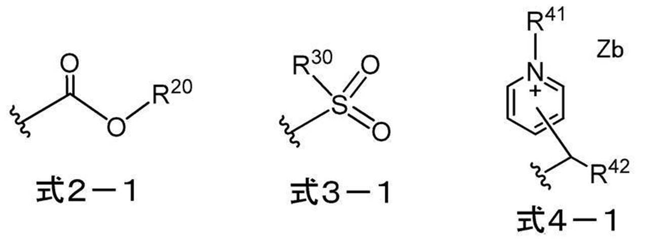
式2-1~式4-1中、R20、R30、R41及びR42はそれぞれ独立に、アルキル基又はアリール基を表し、Zbは電荷を中和する対イオンを表し、波線は、上記式1-1中のLで表される基との結合部位を表す。
<19> 上記変色性化合物が、下記式1-2で表される化合物である<18>に記載の機上現像型平版印刷版原版。

式1-2中、R1は上記式2-1~式4-1のいずれかで表される基を表し、R19~R22はそれぞれ独立に、水素原子、ハロゲン原子、-Ra、-ORb、-CN、-SRc、又は、-NRdReを表し、R23及びR24はそれぞれ独立に、-Raを表し、Ra~Reはそれぞれ独立に、炭化水素基を表し、R19とR20、R21とR22、又は、R23とR24は、連結して単環又は多環を形成してもよく、Lは、酸素原子、硫黄原子、又は、-N(R10)-を表し、R10は、水素原子、アルキル基、又は、アリール基を表し、Rd1~Rd4、W1及びW2は、それぞれ独立に、置換基を有してもよいアルキル基を表し、Zaは電荷を中和する対イオンを表す。
<20> 上記変色性化合物が、下記式1-3~式1-7のいずれかで表される化合物である<18>又は<19>に記載の機上現像型平版印刷版原版。

式1-3~式1-7中、R1は上記式2-1~式4-1のいずれかで表される基を表し、R19~R22はそれぞれ独立に、水素原子、ハロゲン原子、-Ra、-ORb、-CN、-SRc、又は、-NRdReを表し、R25及びR26はそれぞれ独立に、水素原子、ハロゲン原子、又は-Raを表し、Ra~Reはそれぞれ独立に、炭化水素基を表し、R19とR20、R21とR22、又は、R25とR26は、連結して単環又は多環を形成してもよく、Lは、酸素原子、硫黄原子、又は、-N(R10)-を表し、R10は、水素原子、アルキル基、又は、アリール基を表し、Rd1~Rd4、W1及びW2はそれぞれ独立に、置換基を有してもよいアルキル基を表し、Zaは電荷を中和する対イオンを表す。
<21> 上記式1-2~式1-7におけるW1及びW2はそれぞれ独立に、置換基を有するアルキル基であり、かつ、上記置換基として、-OCH2CH2-、スルホ基、スルホ基の塩、カルボキシ基、又は、カルボキシ基の塩を少なくとも有する基である<19>又は<20>に記載の機上現像型平版印刷版原版。
<22> 上記画像記録層が、電子供与型重合開始剤を更に含む、<1>~<21>のいずれか1つに記載の機上現像型平版印刷版原版。
<23> 上記電子供与型重合開始剤が、ボレート化合物である<22>に記載の機上現像型平版印刷版原版。
<24> 上記電子受容型重合開始剤及び上記電子供与型重合開始剤として、上記電子受容性重合開始剤構造を有するカチオンと上記電子供与型重合開始剤構造を有するアニオンとが塩を形成してなる化合物を含む<22>又は<23>に記載の機上現像型平版印刷版原版。
<25> 上記赤外線吸収剤のHOMO-上記電子供与型重合開始剤のHOMOの値が、0.70eV以下である<22>~<24>のいずれか1つに記載の機上現像型平版印刷版原版。
<26> 上記重合性化合物が、7官能以上の重合性化合物を含む<1>~<25>のいずれか1つに記載の機上現像型平版印刷版原版。
<27> 上記重合性化合物が、10官能以上の重合性化合物を含む<1>~<26>のいずれか1つに記載の機上現像型平版印刷版原版。
<28> 上記支持体が、アルミニウム板と、上記アルミニウム板上に配置されたアルミニウムの陽極酸化皮膜とを有し、上記陽極酸化皮膜が、上記アルミニウム板よりも上記画像記録層側に位置し、上記陽極酸化皮膜が、上記画像記録層側の表面から深さ方向にのびるマイクロポアを有し、上記マイクロポアの上記陽極酸化皮膜表面における平均径が、10nmを超え100nm以下である、<1>~<27>のいずれか1つに記載の機上現像型平版印刷版原版。
<29> 上記マイクロポアが、上記陽極酸化皮膜表面から深さ10nm~1,000nmの位置までのびる大径孔部と、上記大径孔部の底部と連通し、連通位置から深さ20nm~2,000nmの位置までのびる小径孔部とから構成され、上記大径孔部の上記陽極酸化皮膜表面における平均径が、15nm~100nmであり、上記小径孔部の上記連通位置における平均径が、13nm以下である、<28>に記載の機上現像型平版印刷版原版。
<30> <1>~<29>のいずれか1つに記載の機上現像型平版印刷版原版を、画像様に露光する工程と、印刷機上で印刷インク及び湿し水よりなる群から選ばれた少なくとも一方を供給して非画像部の画像記録層を除去する工程と、を含む平版印刷版の作製方法。
<31> <1>~<29>のいずれか1つに記載の機上現像型平版印刷版原版を、画像様に露光する工程と、印刷機上で印刷インク及び湿し水よりなる群から選ばれた少なくとも一方を供給して非画像部の画像記録層を除去し平版印刷版を作製する工程と、得られた平版印刷版により印刷する工程と、を含む平版印刷方法。
本開示の一実施形態によれば、経時安定性に優れる機上現像型平版印刷版原版を提供することができる。
また、本開示の他の実施形態によれば、上記機上現像型平版印刷版原版を用いた平版印刷版の作製方法又は平版印刷版の印刷方法を提供することができる。
また、本開示の他の実施形態によれば、上記機上現像型平版印刷版原版を用いた平版印刷版の作製方法又は平版印刷版の印刷方法を提供することができる。
以下において、本開示の内容について詳細に説明する。以下に記載する構成要件の説明は、本開示の代表的な実施態様に基づいてなされることがあるが、本開示はそのような実施態様に限定されるものではない。
なお、本明細書において、数値範囲を示す「~」とはその前後に記載される数値を下限値及び上限値として含む意味で使用される。
本開示中に段階的に記載されている数値範囲において、一つの数値範囲で記載された上限値又は下限値は、他の段階的な記載の数値範囲の上限値又は下限値に置き換えてもよい。また、本開示中に記載されている数値範囲において、その数値範囲の上限値又は下限値は、実施例に示されている値に置き換えてもよい。
また、本明細書における基(原子団)の表記において、置換及び無置換を記していない表記は、置換基を有さないものと共に置換基を有するものをも包含するものである。例えば「アルキル基」とは、置換基を有さないアルキル基(無置換アルキル基)のみならず、置換基を有するアルキル基(置換アルキル基)をも包含するものである。
本明細書において、「(メタ)アクリル」は、アクリル及びメタクリルの両方を包含する概念で用いられる語であり、「(メタ)アクリロイル」は、アクリロイル及びメタクリロイルの両方を包含する概念として用いられる語である。
また、本明細書中の「工程」の用語は、独立した工程だけではなく、他の工程と明確に区別できない場合であっても、その工程の所期の目的が達成されれば本用語に含まれる。 また、本開示において、「質量%」と「重量%」とは同義であり、「質量部」と「重量部」とは同義である。
特に限定しない限りにおいて、本開示において組成物中の各成分、又は、ポリマー中の各構成単位は、1種単独で含まれていてもよいし、2種以上を併用してもよいものとする。
更に、本開示において組成物中の各成分、又は、ポリマー中の各構成単位の量は、組成物中に各成分、又は、ポリマー中の各構成単位に該当する物質又は構成単位が複数存在する場合、特に断らない限り、組成物中に存在する該当する複数の物質、又は、ポリマー中に存在する該当する複数の各構成単位の合計量を意味する。
更に、本開示において、2以上の好ましい態様の組み合わせは、より好ましい態様である。
また、本開示における重量平均分子量(Mw)及び数平均分子量(Mn)は、特に断りのない限り、TSKgel GMHxL、TSKgel G4000HxL、TSKgel G2000HxL(何れも東ソー(株)製の商品名)のカラムを使用したゲルパーミエーションクロマトグラフィ(GPC)分析装置により、溶媒THF(テトラヒドロフラン)、示差屈折計により検出し、標準物質としてポリスチレンを用いて換算した分子量である。
本開示において、「平版印刷版原版」の用語は、平版印刷版原版だけでなく、捨て版原版を包含する。また、「平版印刷版」の用語は、平版印刷版原版を、必要により、露光、現像などの操作を経て作製された平版印刷版だけでなく、捨て版を包含する。捨て版原版の場合には、必ずしも、露光、現像の操作は必要ない。なお、捨て版とは、例えばカラーの新聞印刷において一部の紙面を単色又は2色で印刷を行う場合に、使用しない版胴に取り付けるための平版印刷版原版である。
本開示において、「耐刷性に優れる」とは、平版印刷版の印刷可能な枚数が多いことをいい、印刷の際のインクとして紫外線硬化性インク(UVインク)を用いた場合の耐刷性を、以下、「UV耐刷性」ともいう。
以下、本開示を詳細に説明する。
(機上現像型平版印刷版原版)
本開示に係る機上現像型平版印刷版原版(単に「平版印刷版原版」ともいう。)は、支持体と、画像記録層と、最外層とをこの順で有し、上記画像記録層が、赤外線吸収剤、電子受容型重合開始剤、及び、重合性化合物を含み、上記電子受容型重合開始剤のLUMO-上記赤外線吸収剤のLUMOの値が、0.45eV以上であり、上記最外層が、変色性化合物を含む。
また、本開示に係る機上現像型平版印刷版原版は、ネガ型平版印刷版原版であることが好ましい。
本開示に係る機上現像型平版印刷版原版(単に「平版印刷版原版」ともいう。)は、支持体と、画像記録層と、最外層とをこの順で有し、上記画像記録層が、赤外線吸収剤、電子受容型重合開始剤、及び、重合性化合物を含み、上記電子受容型重合開始剤のLUMO-上記赤外線吸収剤のLUMOの値が、0.45eV以上であり、上記最外層が、変色性化合物を含む。
また、本開示に係る機上現像型平版印刷版原版は、ネガ型平版印刷版原版であることが好ましい。
従来の特許文献1又は2に記載の平版印刷版原版のように、従来のネガ型平版印刷版原版では、経時安定性が十分でない場合があることを本発明者らは見出した。
本発明者らが鋭意検討した結果、上記構成をとることにより、経時安定性に優れる機上現像型平版印刷版原版を提供できることを見出した。
上記効果が得られる詳細なメカニズムは不明であるが、以下のように推測される。
画像記録層が、赤外線吸収剤、電子受容型重合開始剤、及び、重合性化合物を含み、上記電子受容型重合開始剤のLUMO-上記赤外線吸収剤のLUMOの値が、0.45eV以上であることにより、露光前における赤外線吸収剤から電子受容型重合開始剤への電子供与を抑制し、露光前における重合開始種が生じることを抑制するとともに、上記最外層が、変色性化合物を含むことにより、白灯等に起因する重合開始種の生成を抑制し、経時安定性に優れると推定している。
以下、本開示に係る平版印刷版原版における各構成要件の詳細について説明する。
<画像記録層>
本開示に係る平版印刷版原版は、支持体と、画像記録層と、最外層とをこの順で有し、上記画像記録層が、赤外線吸収剤、電子供与型重合開始剤、及び、重合性化合物を含み、上記電子受容型重合開始剤のLUMO-上記赤外線吸収剤のLUMOの値が、0.45eV以上である。
本開示に用いられる画像記録層は、ネガ型画像記録層であることが好ましく、水溶性又は水分散性のネガ型画像記録層であることがより好ましい。
本開示に係る平版印刷版原版は、機上現像性の観点から、画像記録層の未露光部が湿し水及び印刷インクの少なくともいずれかにより除去可能であることが好ましい。
本開示に係る平版印刷版原版は、支持体と、画像記録層と、最外層とをこの順で有し、上記画像記録層が、赤外線吸収剤、電子供与型重合開始剤、及び、重合性化合物を含み、上記電子受容型重合開始剤のLUMO-上記赤外線吸収剤のLUMOの値が、0.45eV以上である。
本開示に用いられる画像記録層は、ネガ型画像記録層であることが好ましく、水溶性又は水分散性のネガ型画像記録層であることがより好ましい。
本開示に係る平版印刷版原版は、機上現像性の観点から、画像記録層の未露光部が湿し水及び印刷インクの少なくともいずれかにより除去可能であることが好ましい。
〔電子受容型重合開始剤と赤外線吸収剤との関係〕
本開示における画像記録層は、上記電子受容型重合開始剤のLUMO-上記赤外線吸収剤のLUMOの値が、0.45eV以上であり、経時安定性、UV版飛び抑制性、GLV適性、感度の向上及びUV耐刷性の観点から、0.58eV以上であることが好ましく、0.62eV以上であることがより好ましく、0.62eV~1.00eVであることが更に好ましく、0.62eV~0.95eVであることが特に好ましい。
なお、マイナスの値は、上記赤外線吸収剤のLUMOが、上記電子受容型重合開始剤のLUMOよりも高くなることを意味する。
本開示における画像記録層は、上記電子受容型重合開始剤のLUMO-上記赤外線吸収剤のLUMOの値が、0.45eV以上であり、経時安定性、UV版飛び抑制性、GLV適性、感度の向上及びUV耐刷性の観点から、0.58eV以上であることが好ましく、0.62eV以上であることがより好ましく、0.62eV~1.00eVであることが更に好ましく、0.62eV~0.95eVであることが特に好ましい。
なお、マイナスの値は、上記赤外線吸収剤のLUMOが、上記電子受容型重合開始剤のLUMOよりも高くなることを意味する。
なお、「版飛び」とは、平版印刷版における画像記録層が膜減りを起こし部分的にインクがつかなくなる現象を指す。平版印刷版における「版飛び」を起こすまでの印刷枚数が、「版飛びが発生しにくい」ことを示す指標となる。また、UVインクを用いた場合であっても、版飛び抑制性に優れることを、UV版飛び抑制性に優れるともいう。
また、平版印刷版原版に対する露光において、GLV(Grating Light Value)技術を採用した露光ヘッドを搭載した露光機が用いられることがある。
この露光機にて露光を行うと、網点画像が走査方向に太ることで、スジ状のムラとして観察される。このスジ状のムラはスワスムラと呼ばれることもある。
上記スジ状のムラの抑制性に優れることを、GLV適性に優れるともいう。
また、平版印刷版原版に対する露光において、GLV(Grating Light Value)技術を採用した露光ヘッドを搭載した露光機が用いられることがある。
この露光機にて露光を行うと、網点画像が走査方向に太ることで、スジ状のムラとして観察される。このスジ状のムラはスワスムラと呼ばれることもある。
上記スジ状のムラの抑制性に優れることを、GLV適性に優れるともいう。
本開示において、最高被占軌道(HOMO)及び最低空軌道(LUMO)のMO(分子軌道)エネルギー計算は、以下の方法により行う。
まず、計算対象となる化合物における遊離の対イオンは計算対象から除外する。例えば、カチオン性の一電子授与型開始剤、カチオン性の赤外線吸収色素では対アニオンを、
アニオン性の一電子供与型開始剤では対カチオンをそれぞれ計算対象から除外する。ここでいう遊離とは、対象とする化合物とその対イオンが共有結合で連結されていないことを意味する。
量子化学計算ソフトウェアGaussian16を用い、構造最適化はDFT(B3LYP/6-31G(d))で行う。
MOエネルギー計算は、上記構造最適化で得た最適構造で量子化学計算ソフトウェアGaussian16を用い、DFT(B3LYP/6-31+G(d,p)/PCM(solvent=methanol))で行う。なお、ヨウ素を含有する化合物は、DFT(B3LYP/DGDZVP/PCM(solvent=methanol))条件にて計算する。
ここでいう最適構造とは、DFT計算で得られる全エネルギーが最も安定な構造を意味する。必要に応じて構造最適化を繰り返すことで、最安定構造を見出す。
上記MOエネルギー計算で得られたMOエネルギーEbare(単位:hartree)を以下の公式により、本開示においてHOMO及びLUMOの値として用いるEscaled(単位:eV)へ変換する。
〔HOMOの算出式〕 Escaled=0.823168×27.2114×Ebare-1.07634
〔LUMOの算出式〕 Escaled=0.820139×27.2114×Ebare-1.086039
なお、27.2114は単にhartreeをeVに変換するための係数であり、HOMOを算出する際に用いる0.823168と-1.07634、およびLUMOを算出する際に用いる0.820139と-1.086039とは調節係数であり、計算対象となる化合物のHOMOとLUMOの計算が実測の値に合うように定める。
以下、画像記録層に含まれる各成分の詳細について説明する。
〔赤外線吸収剤〕
本開示における画像記録層は、赤外線吸収剤を含む。
赤外線吸収剤としては、特に制限はなく、例えば、顔料及び染料が挙げられる。
赤外線吸収剤として用いられる染料としては、市販の染料及び例えば、「染料便覧」(有機合成化学協会編集、昭和45年刊)等の文献に記載されている公知のものが利用できる。具体的には、アゾ染料、金属錯塩アゾ染料、ピラゾロンアゾ染料、ナフトキノン染料、アントラキノン染料、フタロシアニン染料、カルボニウム染料、キノンイミン染料、メチン染料、シアニン染料、スクアリリウム色素、ピリリウム塩、金属チオレート錯体等の染料が挙げられる。
本開示における画像記録層は、赤外線吸収剤を含む。
赤外線吸収剤としては、特に制限はなく、例えば、顔料及び染料が挙げられる。
赤外線吸収剤として用いられる染料としては、市販の染料及び例えば、「染料便覧」(有機合成化学協会編集、昭和45年刊)等の文献に記載されている公知のものが利用できる。具体的には、アゾ染料、金属錯塩アゾ染料、ピラゾロンアゾ染料、ナフトキノン染料、アントラキノン染料、フタロシアニン染料、カルボニウム染料、キノンイミン染料、メチン染料、シアニン染料、スクアリリウム色素、ピリリウム塩、金属チオレート錯体等の染料が挙げられる。
これらの染料のうち好ましいものとしては、シアニン色素、スクアリリウム色素、ピリリウム塩、ニッケルチオレート錯体、インドレニンシアニン色素が挙げられ、より好ましくは、シアニン色素又はインドレニンシアニン色素が挙げられる。中でも、シアニン色素が特に好ましい。
上記赤外線吸収剤としては、メソ位に酸素原子、窒素原子、又はハロゲン原子を有するカチオン性のポリメチン色素であることが好ましい。カチオン性のポリメチン色素としては、シアニン色素、ピリリウム色素、チオピリリウム色素、アズレニウム色素等が好ましく挙げられ、入手の容易性、導入反応時の溶剤溶解性等の観点から、シアニン色素であることが好ましい。
シアニン色素の具体例としては、特開2001-133969号公報の段落0017~0019に記載の化合物、特開2002-023360号公報の段落0016~0021、特開2002-040638号公報の段落0012~0037に記載の化合物、好ましくは特開2002-278057号公報の段落0034~0041、特開2008-195018号公報の段落0080~0086に記載の化合物、特に好ましくは特開2007-90850号公報の段落0035~0043に記載の化合物、特開2012-206495号公報の段落0105~0113に記載の化合物が挙げられる。
また、特開平5-5005号公報の段落0008~0009、特開2001-222101号公報の段落0022~0025に記載の化合物も好ましく使用することができる。 顔料としては、特開2008-195018号公報の段落0072~0076に記載の化合物が好ましい。
また、特開平5-5005号公報の段落0008~0009、特開2001-222101号公報の段落0022~0025に記載の化合物も好ましく使用することができる。 顔料としては、特開2008-195018号公報の段落0072~0076に記載の化合物が好ましい。
また、赤外線吸収剤は、下記式1で表される化合物を含むことが好ましい。

式1中、R1及びR2はそれぞれ独立に、水素原子又はアルキル基を表し、R1及びR2は互いに連結して環を形成してもよく、R3~R6はそれぞれ独立に、水素原子又はアルキル基を表し、R7及びR8はそれぞれ独立に、アルキル基又はアリール基を表し、Y1及びY2はそれぞれ独立に、酸素原子、硫黄原子、-NR0-又はジアルキルメチレン基を表し、R0は水素原子、アルキル基又はアリール基を表し、Ar1及びAr2はそれぞれ独立に、後述する式2で表される基を有していてもよいベンゼン環又はナフタレン環を形成する基を表し、A1は、-NR9R10、-X1-L1又は後述する式2で表される基を表し、R9及びR10はそれぞれ独立に、アルキル基、アリール基、アルコキシカルボニル基又はアリールスルホニル基を表し、X1は酸素原子又は硫黄原子を表し、L1は炭化水素基、ヘテロアリール基、又は、熱若しくは赤外線露光によりX1との結合が開裂する基を表し、Zaは電荷を中和する対イオンを表し、Ar1及びAr2の少なくとも一方に、下記式2で表される基を有する。
-X 式2
式2中、Xは、ハロゲン原子、-C(=O)-X2-R11、-C(=O)-NR12R13、-O-C(=O)-R14、-CN、-SO2NR15R16、又は、パーフルオロアルキル基を表し、X2は、単結合又は酸素原子を表し、R11及びR14はそれぞれ独立に、アルキル基又はアリール基を表し、R12、R13、R15及びR16はそれぞれ独立に、水素原子、アルキル基又はアリール基を表す。
-X 式2
式2中、Xは、ハロゲン原子、-C(=O)-X2-R11、-C(=O)-NR12R13、-O-C(=O)-R14、-CN、-SO2NR15R16、又は、パーフルオロアルキル基を表し、X2は、単結合又は酸素原子を表し、R11及びR14はそれぞれ独立に、アルキル基又はアリール基を表し、R12、R13、R15及びR16はそれぞれ独立に、水素原子、アルキル基又はアリール基を表す。
Ar1及びAr2はそれぞれ独立に、ベンゼン環又はナフタレン環を形成する基を表す。上記ベンゼン環及びナフタレン環上には、-X以外の置換基を有していてもよい。置換基としては、アルキル基、アルコキシ基、アリーロキシ基、アミノ基、アルキルチオ基、アリールチオ基、カルボキシ基、カルボキシレート基、スルホ基、スルホネート基、及び、これらを組み合わせた基等が挙げられるが、アルキル基であることが好ましい。
また、式1においては、Ar1及びAr2の少なくとも一方に、上記式2で表される基を有し、耐刷性、視認性、及び、画像記録層の形成に用いる塗布液の経時における保存安定性(経時安定性)の観点から、Ar1及びAr2の両方に、上記式2で表される基を有することが好ましい。
また、式1においては、Ar1及びAr2の少なくとも一方に、上記式2で表される基を有し、耐刷性、視認性、及び、画像記録層の形成に用いる塗布液の経時における保存安定性(経時安定性)の観点から、Ar1及びAr2の両方に、上記式2で表される基を有することが好ましい。
式2におけるXは、ハロゲン原子、-C(=O)-X2-R11、-C(=O)-NR12R13、-O-C(=O)-R14、-CN、-SO2NR15R16、又は、パーフルオロアルキル基を表し、耐刷性、視認性及び経時安定性の観点から、ハロゲン原子、-C(=O)-X2-R11、-C(=O)-NR12R13、-O-C(=O)-R14、CN、又は、-SO2NR15R16であることが好ましく、ハロゲン原子、-C(=O)-O-R11、-C(=O)-NR12R13、又は、-O-C(=O)-R14であることが好ましく、ハロゲン原子、-C(=O)-O-R11、又は、-O-C(=O)-R14であることが更に好ましく、フッ素原子、塩素原子、臭素原子、又は、-C(=O)OR17であることが更に好ましく、塩素原子、又は、臭素原子であることが特に好ましい。
また、Ar1に置換するXと、Ar2に置換するXと、A1のXとは、同じ基であってもよいし、異なる基であってもよい。また、Ar1に置換するXと、Ar2に置換するXとは、耐刷性、視認性及び経時安定性の観点から、同じ基であることが好ましい。
また、Ar1に置換するXと、Ar2に置換するXと、A1のXとは、同じ基であってもよいし、異なる基であってもよい。また、Ar1に置換するXと、Ar2に置換するXとは、耐刷性、視認性及び経時安定性の観点から、同じ基であることが好ましい。
X2は、単結合又は酸素原子を表し、酸素原子であることが好ましい。
R11及びR14はそれぞれ独立に、アルキル基又はアリール基を表し、炭素数1~12のアルキル基又は炭素数6~12のアリール基であることが好ましく、炭素数1~12のアルキル基であることがより好ましい。
R12、R13、R15及びR16はそれぞれ独立に、水素原子、アルキル基又はアリール基を表し、水素原子、炭素数1~12のアルキル基又は炭素数6~12のアリール基であることが好ましく、水素原子又は炭素数1~12のアルキル基であることがより好ましく、炭素数1~12のアルキル基であることが更に好ましい。
R17は、アルキル基又はアリール基を表し、炭素数1~12のアルキル基又は炭素数6~12のアリール基であることが好ましく、炭素数1~12のアルキル基であることがより好ましい。
A1は、-NR9R10、-X1-L1又は-Xを表し、耐刷性、視認性及び経時安定性の観点から、-NR9R10又は-X1-L1であることが好ましく、-NR18R19、-S-R20であることがより好ましい。
また、A1は、UV版飛び抑制性、GLV適性及びUV耐刷性の観点からは、-Xであることが好ましく、ハロゲン原子であることがより好ましく、塩素原子、又は、臭素原子であることが更に好ましく、塩素原子であることが特に好ましい。
R9及びR10はそれぞれ独立に、アルキル基、アリール基、アルコキシカルボニル基又はアリールスルホニル基を表し、炭素数1~12のアルキル基又は炭素数6~12のアリール基であることが好ましく、炭素数1~12のアルキル基であることがより好ましい。
X1は酸素原子又は硫黄原子を表し、L1が炭化水素基又はヘテロアリール基である場合は、硫黄原子であることが好ましく、L1が熱若しくは赤外線露光によりX1との結合が開裂する基であることが好ましい。
L1は炭化水素基、ヘテロアリール基、又は、熱若しくは赤外線露光によりX1との結合が開裂する基を表し、耐刷性の観点からは、炭化水素基又はヘテロアリール基が好ましく、アリール基又はヘテロアリール基がより好ましく、ヘテロアリール基が更に好ましい。
また、L1は、視認性及び経時における退色抑制性の観点からは、熱若しくは赤外線露光によりX1との結合が開裂する基が好ましい。
熱若しくは赤外線露光によりX1との結合が開裂する基については、後述する。
R18及びR19はそれぞれ独立に、アリール基を表し、炭素数6~20のアリール基であることが好ましく、フェニル基であることがより好ましい。
R20は炭化水素基又はヘテロアリール基を表し、アリール基又はヘテロアリール基が好ましく、ヘテロアリール基がより好ましい。
L1及びR20におけるヘテロアリール基としては、下記の基が好ましく挙げられる。

R1~R10、及びR0におけるアルキル基は、炭素数1~30のアルキル基が好ましく、炭素数1~15のアルキル基がより好ましく、炭素数1~10のアルキル基が更に好ましい。上記アルキル基は、直鎖状であっても、分岐を有していても、環構造を有していてもよい。
具体的には、例えば、メチル基、エチル基、プロピル基、ブチル基、ペンチル基、ヘキシル基、ヘプチル基、オクチル基、ノニル基、デシル基、ウンデシル基、ドデシル基、トリデシル基、ヘキサデシル基、オクタデシル基、エイコシル基、イソプロピル基、イソブチル基、s-ブチル基、t-ブチル基、イソペンチル基、ネオペンチル基、1-メチルブチル基、イソヘキシル基、2-エチルヘキシル基、2-メチルヘキシル基、シクロヘキシル基、シクロペンチル基、及び、2-ノルボルニル基を挙げられる。
これらアルキル基の中でも、メチル基、エチル基、プロピル基又はブチル基が特に好ましい。
具体的には、例えば、メチル基、エチル基、プロピル基、ブチル基、ペンチル基、ヘキシル基、ヘプチル基、オクチル基、ノニル基、デシル基、ウンデシル基、ドデシル基、トリデシル基、ヘキサデシル基、オクタデシル基、エイコシル基、イソプロピル基、イソブチル基、s-ブチル基、t-ブチル基、イソペンチル基、ネオペンチル基、1-メチルブチル基、イソヘキシル基、2-エチルヘキシル基、2-メチルヘキシル基、シクロヘキシル基、シクロペンチル基、及び、2-ノルボルニル基を挙げられる。
これらアルキル基の中でも、メチル基、エチル基、プロピル基又はブチル基が特に好ましい。
また、上記アルキル基は、置換基を有していてもよい。置換基の例としては、アルコキシ基、アリーロキシ基、アミノ基、アルキルチオ基、アリールチオ基、ハロゲン原子、カルボキシ基、カルボキシレート基、スルホ基、スルホネート基、アルキルオキシカルボニル基、アリールオキシカルボニル基、及び、これらを組み合わせた基等が挙げられる。
R9、R10、R18、R19及びR0におけるアリール基としては、炭素数6~30のアリール基が好ましく、炭素数6~20のアリール基がより好ましく、炭素数6~12のアリール基が更に好ましい。
また、上記アリール基は、置換基を有していてもよい。置換基の例としては、アルキル基、アルコキシ基、アリーロキシ基、アミノ基、アルキルチオ基、アリールチオ基、ハロゲン原子、カルボキシ基、カルボキシレート基、スルホ基、スルホネート基、アルキルオキシカルボニル基、アリールオキシカルボニル基、及び、これらを組み合わせた基等が挙げられる。
上記アリール基としては具体的には、例えば、フェニル基、ナフチル基、p-トリル基、p-クロロフェニル基、p-フルオロフェニル基、p-メトキシフェニル基、p-ジメチルアミノフェニル基、p-メチルチオフェニル基、p-フェニルチオフェニル基等が挙げられる。
これらアリール基の中で、フェニル基、p-メトキシフェニル基、p-ジメチルアミノフェニル基、又は、ナフチル基が好ましい。
R1及びR2は、連結して環を形成していることが好ましい。
R1及びR2が連結して環を形成する場合、好ましい環員数は5又は6員環が好ましく、6員環がより好ましい。また、R1及びR2が連結して形成される環は、エチレン性不飽和結合を有していてもよい炭化水素環であることが好ましい。
R1及びR2が連結して環を形成する場合、好ましい環員数は5又は6員環が好ましく、6員環がより好ましい。また、R1及びR2が連結して形成される環は、エチレン性不飽和結合を有していてもよい炭化水素環であることが好ましい。
Y1及びY2はそれぞれ独立に、酸素原子、硫黄原子、-NR0-又はジアルキルメチレン基を表し、-NR0-又は ジアルキルメチレン基が好ましく、ジアルキルメチレン基がより好ましい。
R0は水素原子、アルキル基又はアリール基を表し、アルキル基であることが好ましい。
R0は水素原子、アルキル基又はアリール基を表し、アルキル基であることが好ましい。
R7及びR8は、同じ基であることが好ましい。
また、R7及びR8はそれぞれ独立に、直鎖アルキル基又は末端にスルホネート基を有するアルキル基であることが好ましく、メチル基、エチル基又は末端にスルホネート基を有するブチル基であることがより好ましい。
また、上記スルホネート基の対カチオンは、式1中の窒素原子上のカチオンであってもよいし、アルカリ金属カチオンやアルカリ土類金属カチオンであってもよい。
更に、式1で表される化合物の水溶性をさせる観点から、R7及びR8はそれぞれ独立に、アニオン構造を有するアルキル基であることが好ましく、カルボキシレート基又はスルホネート基を有するアルキル基であることがより好ましく、末端にスルホネート基を注するアルキル基であることが更に好ましい。
また、式1で表される化合物の極大吸収波長を長波長化し、また、視認性及び平版印刷版における耐刷性の観点から、R7及びR8はそれぞれ独立に、芳香環を有するアルキル基であることが好ましく、末端に芳香環を有するアルキル基であることがより好ましく、2-フェニルエチル基、2-ナフタレニルエチル基、又は、2-(9-アントラセニル)エチル基であることが特に好ましい。
R3~R6はそれぞれ独立に、水素原子又はアルキル基を表し、水素原子であることが好ましい。
また、式1で表される化合物は、経時安定性、UV版飛び抑制性、GLV適性及びUV耐刷性の観点から、ハロゲン原子を1つ以上有することが好ましく、A1、Ar1及びAr2よりなる群から選ばれる少なくとも1つに、ハロゲン原子を1つ以上有することがより好ましく、A1、Ar1及びAr2がそれぞれハロゲン原子を1つ以上有することが特に好ましい。
更に、式1で表される化合物は、経時安定性、UV版飛び抑制性、GLV適性及びUV耐刷性の観点から、ハロゲン原子を2つ以上有することがより好ましく、ハロゲン原子を3つ以上有することが更に好ましく、ハロゲン原子を3つ以上6つ以下有することが特に好ましい。
また、上記ハロゲン原子としては、塩素原子、又は、臭素原子が好ましく挙げられる。
更にまた、式1で表される化合物は、経時安定性、UV版飛び抑制性、GLV適性及びUV耐刷性の観点から、Ar1及びAr2の少なくとも1方に、ハロゲン原子を有することが好ましく、Ar1及びAr2の少なくとも1方に、塩素原子、又は、臭素原子を有することがより好ましく、Ar1及びAr2の少なくとも1方に、臭素原子を有することが更に好ましく、Ar1及びAr2の両方に、臭素原子を有することが特に好ましい。
Zaは、電荷を中和する対イオンを表し、アニオン種を示す場合は、スルホネートイオン、カルボキシレートイオン、テトラフルオロボレートイオン、ヘキサフルオロホスフェートイオン、過塩素酸塩イオン、スルホンアミドアニオン、スルホンイミドアニオン等が挙げられる。カチオン種を示す場合は、アルカリ金属イオン、アルカリ土類金属イオン、アンモニウムイオン、ピリジニウムイオン又はスルホニウムイオンが好ましく、ナトリウムイオン、カリウムイオン、アンモニウムイオン、ピリジニウムイオン又はスルホニウムイオンがより好ましく、ナトリウムイオン、カリウムイオン又はアンモニウムイオンが更に好ましく、ナトリウムイオン、カリウムイオン又はトリアルキルアンモニウムイオンが特に好ましい。
中でも、Zaは、耐刷性及び視認性の観点から、炭素原子を含む有機アニオンであることが好ましく、スルホネートイオン、カルボキシレートイオン、スルホンアミドアニオン又はスルホンイミドアニオンであることがより好ましく、スルホンアミドアニオン又はスルホンイミドアニオンであることが更に好ましく、スルホンイミドアニオンであることが特に好ましい。
R1~R8、R0、A1、Ar1、Ar2、Y1及びY2は、アニオン構造やカチオン構造を有していてもよく、R1~R8、R0、A1、Ar1、Ar2、Y1及びY2の全てが電荷的に中性の基であれば、Zaは一価の対アニオンであるが、例えば、R1~R8、R0、A1、Ar1、Ar2、Y1及びY2に2以上のアニオン構造を有する場合、Zaは対カチオンにもなり得る。
また、式1において、Za以外の部分が電荷的に中性であれば、Zaはなくともよい。
スルホンアミドアニオンとしては、アリールスルホンアミドアニオンが好ましい。
また、スルホンイミドアニオンとしては、ビスアリールスルホンイミドアニオンが好ましい。
スルホンアミドアニオン又はスルホンイミドアニオンの具体例を以下に示すが、本開示はこれらに限定されるものではない。下記具体例中、Phはフェニル基を、Meはメチル基を、Etはエチル基を、それぞれ表す。
また、スルホンイミドアニオンとしては、ビスアリールスルホンイミドアニオンが好ましい。
スルホンアミドアニオン又はスルホンイミドアニオンの具体例を以下に示すが、本開示はこれらに限定されるものではない。下記具体例中、Phはフェニル基を、Meはメチル基を、Etはエチル基を、それぞれ表す。
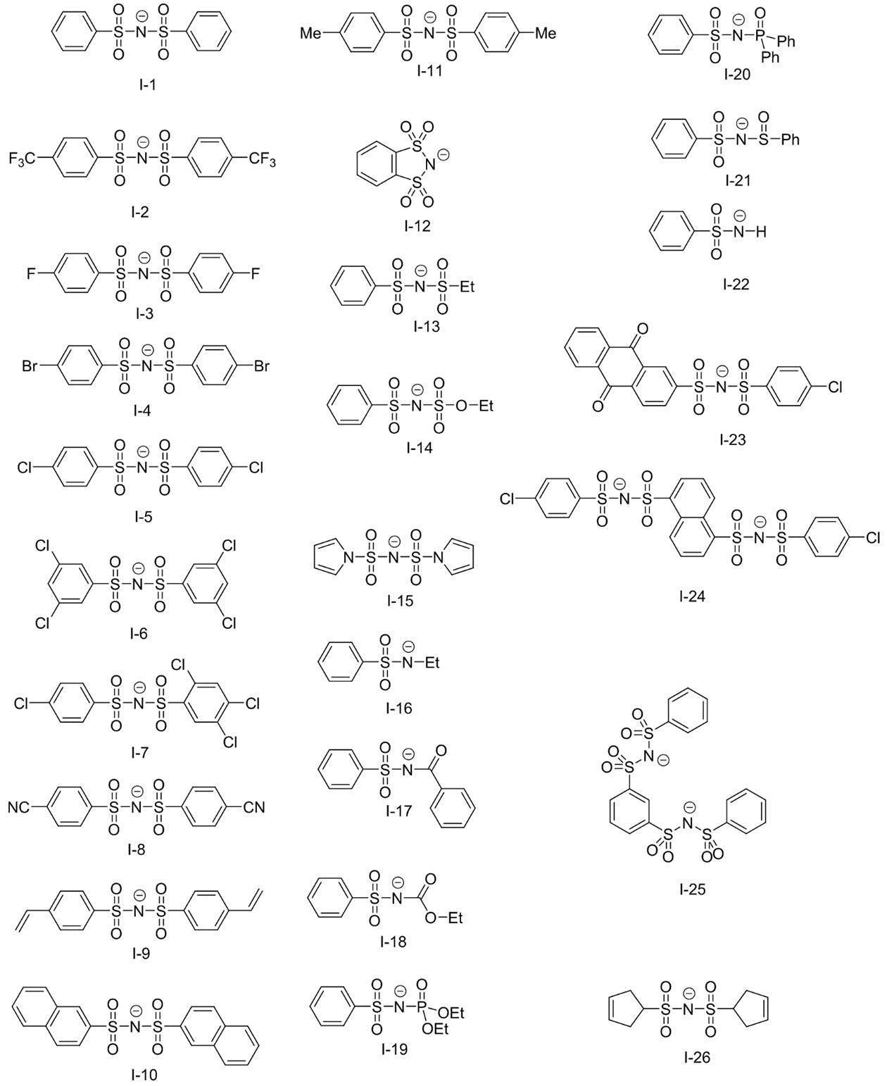
上記熱又は赤外線露光によりX1との結合が開裂する基は、視認性の観点から、下記式(1-1)~式(1-7)のいずれかで表される基であることが好ましく、下記式(1-1)~式(1-3)のいずれかで表される基であることがより好ましい。

式(1-1)~式(1-7)中、●は、式1中のX1との結合部位を表し、R10はそれぞれ独立に、水素原子、アルキル基、アルケニル基、アリール基、-OR14、-NR15R16又は-SR17を表し、R11はそれぞれ独立に、水素原子、アルキル基又はアリール基を表し、R12はアリール基、-OR14、-NR15R16、-SR17、-C(=O)R18、-OC(=O)R18又はハロゲン原子を表し、R13はアリール基、アルケニル基、アルコキシ基又はオニウム基を表し、R14~R17はそれぞれ独立に、水素原子、アルキル基又はアリール基を表し、R18はそれぞれ独立に、アルキル基、アリール基、-OR14、-NR15R16又は-SR17を表し、Z1は電荷を中和する対イオンを表す。
R10、R11及びR14~R18がアルキル基である場合の好ましい態様は、R2~R9及びR0におけるアルキル基の好ましい態様と同様である。
R10及びR13におけるアルケニル基の炭素数は、1~30であることが好ましく、1~15であることがより好ましく、1~10であることが更に好ましい。
R10~R18がアリール基である場合の好ましい態様は、R0におけるアリール基の好ましい態様と同様である。
R10及びR13におけるアルケニル基の炭素数は、1~30であることが好ましく、1~15であることがより好ましく、1~10であることが更に好ましい。
R10~R18がアリール基である場合の好ましい態様は、R0におけるアリール基の好ましい態様と同様である。
視認性の観点から、式(1-1)におけるR10は、アルキル基、アルケニル基、アリール基、-OR14、-NR15R16又は-SR17であることが好ましく、アルキル基、-OR14、-NR15R16又は-SR17であることがより好ましく、アルキル基又は-OR14であることが更に好ましく、-OR14であることが特に好ましい。
また、式(1-1)におけるR10がアルキル基である場合、上記アルキル基は、α位にアリールチオ基又はアルキルオキシカルボニル基を有するアルキル基であることが好ましい。
式(1-1)におけるR10が-OR14である場合、R14は、アルキル基であることが好ましく、炭素数1~8のアルキル基であることがより好ましく、イソプロピル基又はt-ブチル基であることが更に好ましく、t-ブチル基であることが特に好ましい。
また、式(1-1)におけるR10がアルキル基である場合、上記アルキル基は、α位にアリールチオ基又はアルキルオキシカルボニル基を有するアルキル基であることが好ましい。
式(1-1)におけるR10が-OR14である場合、R14は、アルキル基であることが好ましく、炭素数1~8のアルキル基であることがより好ましく、イソプロピル基又はt-ブチル基であることが更に好ましく、t-ブチル基であることが特に好ましい。
視認性の観点から、式(1-2)におけるR11は、水素原子であることが好ましい。
また、視認性の観点から、式(1-2)におけるR12は、-C(=O)OR14、-OC(=O)OR14又はハロゲン原子であることが好ましく、-C(=O)OR14又は-OC(=O)OR14であることがより好ましい。式(1-2)におけるR12が-C(=O)OR14又は-OC(=O)OR14である場合、R14は、アルキル基であることが好ましい。
また、視認性の観点から、式(1-2)におけるR12は、-C(=O)OR14、-OC(=O)OR14又はハロゲン原子であることが好ましく、-C(=O)OR14又は-OC(=O)OR14であることがより好ましい。式(1-2)におけるR12が-C(=O)OR14又は-OC(=O)OR14である場合、R14は、アルキル基であることが好ましい。
視認性の観点から、式(1-3)におけるR11はそれぞれ独立に、水素原子又はアルキル基であることが好ましく、また、式(1-3)における少なくとも1つのR11が、アルキル基であることがより好ましい。
また、R11におけるアルキル基は、炭素数1~10のアルキル基であることが好ましく、炭素数3~10のアルキル基であることがより好ましい。
更に、R11におけるアルキル基は、分岐を有するアルキル基、又は、シクロアルキル基であることが好ましく、第二級又は第三級アルキル基、又は、シクロアルキル基であることがより好ましく、イソプロピル基、シクロペンチル基、シクロヘキシル基、又は、t-ブチル基であることが更に好ましい。
また、視認性の観点から、式(1-3)におけるR13は、アリール基、アルコキシ基又はオニウム基であることが好ましく、p-ジメチルアミノフェニル基又はピリジニウム基であることがより好ましく、ピリジニウム基であることが更に好ましい。
R13におけるオニウム基としては、ピリジニウム基、アンモニウム基、スルホニウム基等が挙げられる。オニウム基は、置換基を有していてもよい。置換基としては、アルキル基、アルコキシ基、アリーロキシ基、アミノ基、アルキルチオ基、アリールチオ基、ハロゲン原子、カルボキシ基、スルホ基、アルキルオキシカルボニル基、アリールオキシカルボニル基、及び、これらを組み合わせた基等が挙げられるが、アルキル基、アリール基及びこれらを組み合わせた基であることが好ましい。
中でも、ピリジニウム基が好ましく、N-アルキル-3-ピリジニウム基、N-ベンジル-3-ピリジニウム基、N-(アルコキシポリアルキレンオキシアルキル)-3-ピリジニウム基、N-アルコキシカルボニルメチル-3-ピリジニウム基、N-アルキル-4-ピリジニウム基、N-ベンジル-4-ピリジニウム基、N-(アルコキシポリアルキレンオキシアルキル)-4-ピリジニウム基、N-アルコキシカルボニルメチル-4-ピリジニウム基、又は、N-アルキル-3,5-ジメチル-4-ピリジニウム基がより好ましく、N-アルキル-3-ピリジニウム基、又は、N-アルキル-4-ピリジニウム基が更に好ましく、N-メチル-3-ピリジニウム基、N-オクチル-3-ピリジニウム基、N-メチル-4-ピリジニウム基、又は、N-オクチル-4-ピリジニウム基が特に好ましく、N-オクチル-3-ピリジニウム基、又は、N-オクチル-4-ピリジニウム基が最も好ましい。
また、R13がピリジニウム基である場合、対アニオンとしては、スルホネートイオン、カルボキシレートイオン、テトラフルオロボレートイオン、ヘキサフルオロホスフェートイオン、p-トルエンスルホネートイオン、過塩素酸塩イオン等が挙げられ、p-トルエンスルホネートイオン、又は、ヘキサフルオロホスフェートイオンが好ましい。
視認性の観点から、式(1-4)におけるR10は、アルキル基又はアリール基であることが好ましく、2つのR10のうち、一方がアルキル基、他方がアリール基であることがより好ましい。
視認性の観点から、式(1-5)におけるR10は、アルキル基又はアリール基であることが好ましく、アリール基であることがより好ましく、p-メチルフェニル基であることが更に好ましい。
視認性の観点から、式(1-6)におけるR10はそれぞれ独立に、アルキル基又はアリール基であることが好ましく、メチル基又はフェニル基であることがより好ましい。
視認性の観点から、式(1-7)におけるZ1は、電荷を中和する対イオンであればよく、化合物全体として、上記Zaに含まれてもよい。
Z1は、スルホネートイオン、カルボキシレートイオン、テトラフルオロボレートイオン、ヘキサフルオロホスフェートイオン、p-トルエンスルホネートイオン、又は、過塩素酸塩イオンであることが好ましく、p-トルエンスルホネートイオン、又は、ヘキサフルオロホスフェートイオンであることがより好ましい。
また、上記熱若しくは赤外線露光によりX1との結合が開裂する基は、式(1-8)で表される基であることが特に好ましい。

式(1-8)中、●は、式1中のX1との結合部位を表し、R19及びR20はそれぞれ独立に、アルキル基を表し、Za’は、電荷を中和する対イオンを表す。
式(1-8)におけるピリジニウム環とR20を含む炭化水素基との結合位置は、ピリジニウム環の3位又は4位であることが好ましく、ピリジニウム環の4位であることがより好ましい。
R19及びR20におけるアルキル基は、直鎖状であっても、分岐を有していても、環構造を有していてもよい。
また、上記アルキル基は、置換基を有していてもよく、置換基としては、アルコキシ基、及び、末端アルコキシポリアルキレンオキシ基が好ましく挙げられる。
R19は、炭素数1~12のアルキル基であることが好ましく、炭素数1~12の直鎖アルキル基であることがより好ましく、炭素数1~8の直鎖アルキル基であることが更に好ましく、メチル基又はn-オクチル基であることが特に好ましい。
R20は、炭素数1~8のアルキル基であることが好ましく、炭素数3~8の分岐アルキル基であることがより好ましく、イソプロピル基又はt-ブチル基であることが更に好ましく、イソプロピル基であることが特に好ましい。
Za’は、電荷を中和する対イオンであればよく、化合物全体として、上記Zaに含まれてもよい。
Za’は、スルホネートイオン、カルボキシレートイオン、テトラフルオロボレートイオン、ヘキサフルオロホスフェートイオン、p-トルエンスルホネートイオン、又は、過塩素酸塩イオンであることが好ましく、p-トルエンスルホネートイオン、又は、ヘキサフルオロホスフェートイオンであることがより好ましい。
以下に式1で表される化合物の好ましい具体例として、母核構造A-1~A-54、対アニオンB-1~B-10及び対カチオンC-1~C-3を挙げるが、本開示はこれに限定されるものではない。なお、式1で表される化合物の具体例は、母核構造A-1~A-9、A-11~A-20及びA-22~A-54と、対アニオンB-1~B-10とをそれぞれ1つずつ組み合わせた化合物、並びに、母核構造A-10及びA-21と対カチオンC-1~C-3とをそれぞれ1つずつ組み合わせた化合物である。


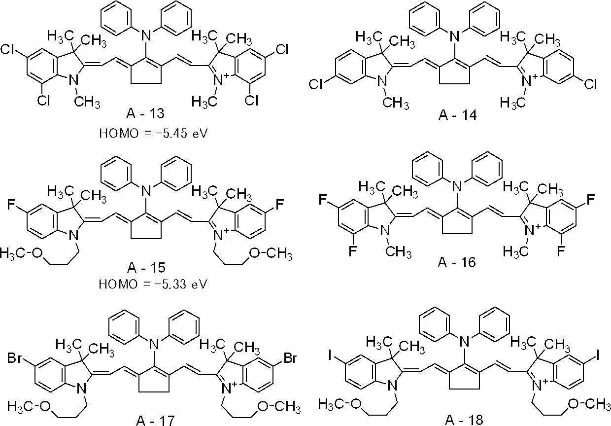


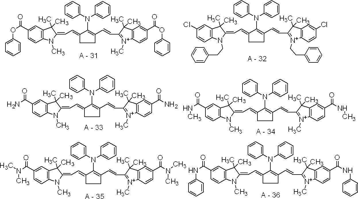


また、式1で表される化合物としては、下記に示す化合物も好適に用いることができる。なお、TsO-は、トシレートアニオンを表す。


式1で表される化合物の作製方法は、特に制限はなく、公知のシアニン色素の作製方法を参照し、作製することができる。また、国際公開第2016/027886号に記載の方法も好適に用いることができる。
上記赤外線吸収剤の最高被占軌道(HOMO)は、耐刷性及び視認性の観点から、-5.250eV以下であることが好ましく、-5.30eV以下であることがより好ましく、-5.80eV以上-5.35eV以下であることが更に好ましく、-5.65eV以上-5.40eV以下であることが特に好ましい。
上記赤外線吸収剤の最低空軌道(LUMO)は、経時安定性、UV版飛び抑制性、GLV適性、感度の向上及びUV耐刷性の観点から、-3.70eVより小さいことが好ましく、-3.80eVより小さいことがより好ましく、-4.20eV以上-3.80eV未満であることが更に好ましく、-4.00eV以上-3.80eV未満であることが特に好ましい。
赤外線吸収剤は、1種のみを用いてもよいし、2種以上を併用してもよい。
また、赤外線吸収剤として顔料と染料とを併用してもよい。
また、赤外線吸収剤として顔料と染料とを併用してもよい。
赤外線吸収剤の含有量は、画像記録層の全質量に対し、0.1質量%~10.0質量%が好ましく、0.5質量%~5.0質量%がより好ましい。
〔電子受容型重合開始剤〕
本開示における画像記録層は、電子受容型重合開始剤を含む。
電子受容型重合開始剤は、赤外線露光により赤外線吸収剤の電子が励起した際に、分子間電子移動で一電子を受容することにより、ラジカル等の重合開始種を発生する化合物である。
電子受容型重合開始剤は、光、熱あるいはその両方のエネルギーによりラジカル、カチオン等の重合開始種を発生する化合物であって、公知の熱重合開始剤、結合解離エネルギーの小さな結合を有する化合物、光重合開始剤などを適宜選択して用いることができる。
電子受容型重合開始剤としては、ラジカル重合開始剤が好ましく、オニウム塩化合物がより好ましい。
また、電子受容型重合開始剤としては、赤外線感光性重合開始剤であることが好ましい。
更に、電子受容型重合開始剤としては、経時安定性、UV版飛び抑制性、GLV適性、感度の向上及びUV耐刷性の観点から、ヨードニウム塩化合物、又は、ハロゲン化アルキル基を有する化合物であることが好ましく、ハロゲン化アルキル基を有する化合物であることがより好ましい。
また、ハロゲン化アルキル基を有する化合物としては、経時安定性、UV版飛び抑制性、GLV適性、感度の向上及びUV耐刷性の観点から、パーハロゲノアルキルスルホニル基を有する化合物が好ましく、トリハロゲノメチルスルホニル基を有する化合物がより好ましく、トリブロモメチルスルホニル基を有する化合物であることが特に好ましい。
上記電子受容型重合開始剤の中でも好ましいものとして、硬化性の観点から、オキシムエステル化合物及びオニウム塩化合物が挙げられる。中でも、耐刷性の観点から、ヨードニウム塩化合物、スルホニウム塩化合物又はアジニウム塩化合物が好ましく、ヨードニウム塩化合物又はスルホニウム塩化合物がより好ましく、ヨードニウム塩化合物が特に好ましい。
これら化合物の具体例を以下に示すが、本開示はこれに限定されるものではない。
これら化合物の具体例を以下に示すが、本開示はこれに限定されるものではない。
ヨードニウム塩化合物の例としては、ジアリールヨードニウム塩化合物が好ましく、特に電子供与性基、例えば、アルキル基又はアルコキシル基で置換されたジフェニルヨードニウム塩化合物がより好ましく、また、非対称のジフェニルヨードニウム塩化合物が好ましい。具体例としては、ジフェニルヨードニウム=ヘキサフルオロホスファート、4-メトキシフェニル-4-(2-メチルプロピル)フェニルヨードニウム=ヘキサフルオロホスファート、4-(2-メチルプロピル)フェニル-p-トリルヨードニウム=ヘキサフルオロホスファート、4-ヘキシルオキシフェニル-2,4,6-トリメトキシフェニルヨードニウム=ヘキサフルオロホスファート、4-ヘキシルオキシフェニル-2,4-ジエトキシフェニルヨードニウム=テトラフルオロボラート、4-オクチルオキシフェニル-2,4,6-トリメトキシフェニルヨードニウム=1-ペルフルオロブタンスルホナート、4-オクチルオキシフェニル-2,4,6-トリメトキシフェニルヨードニウム=ヘキサフルオロホスファー飛びス(4-t-ブチルフェニル)ヨードニウム=ヘキサフルオロホスファートが挙げられる。
また、ヨードニウム塩化合物及びスルホニウム塩化合物の対アニオンの例としては、スルホネートアニオン、カルボキシレートアニオン、テトラフルオロボレートアニオン、ヘキサフルオロホスフェートアニオン、p-トルエンスルホネートアニオン、トシレートアニオン、スルホンアミドアニオン又はスルホンイミドアニオンが挙げられる。
中でも、スルホンアミドアニオン又はスルホンイミドアニオンが好ましく、スルホンイミドアニオンがより好ましい。
スルホンアミドアニオンとしては、アリールスルホンアミドアニオンが好ましい。
また、スルホンイミドアニオンとしては、ビスアリールスルホンイミドアニオンが好ま
しい。
スルホンアミドアニオン又はスルホンイミドアニオンの具体例としては、国際公開第2019/013268号に記載されているものが挙げられる。
中でも、スルホンアミドアニオン又はスルホンイミドアニオンが好ましく、スルホンイミドアニオンがより好ましい。
スルホンアミドアニオンとしては、アリールスルホンアミドアニオンが好ましい。
また、スルホンイミドアニオンとしては、ビスアリールスルホンイミドアニオンが好ま
しい。
スルホンアミドアニオン又はスルホンイミドアニオンの具体例としては、国際公開第2019/013268号に記載されているものが挙げられる。
また、上記電子受容型重合開始剤としては、露光後の経時視認性、現像性、及び、得られる平版印刷版におけるUV耐刷性の観点から、下記式(II)又は式(III)で表される化合物を含むことが好ましく、式(II)で表される化合物を含むことが特に好ましい。

式(II)及び式(III)中、XAはハロゲン原子を表し、RA、RA1及びRA2はそれぞれ独立に、炭素数1~20の一価の炭化水素基を表す。
式(II)におけるRAは、アリール基であることが好ましい。
式(II)及び式(III)におけるXAとしては、フッ素原子、塩素原子、臭素原子及びヨウ素原子が挙げられる。これらのうち、塩素原子又は臭素原子は、感度に優れるため好ましく、臭素原子が特に好ましい。
また、式(II)及び式(III)において、RA、RA1及びRA2はそれぞれ独立に、アリール基であることが好ましく、中でも、感度と保存安定性とのバランスに優れる観点から、アミド基で置換されているアリール基がより好ましい。
式(II)及び式(III)におけるXAとしては、フッ素原子、塩素原子、臭素原子及びヨウ素原子が挙げられる。これらのうち、塩素原子又は臭素原子は、感度に優れるため好ましく、臭素原子が特に好ましい。
また、式(II)及び式(III)において、RA、RA1及びRA2はそれぞれ独立に、アリール基であることが好ましく、中でも、感度と保存安定性とのバランスに優れる観点から、アミド基で置換されているアリール基がより好ましい。
また、上記電子受容型重合開始剤としては、式(IV)で表される化合物を含むことが特に好ましい。
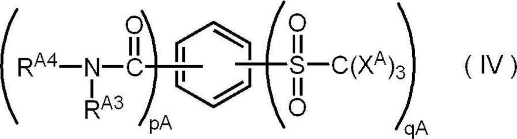
式(IV)中、XAはハロゲン原子を表し、RA3及びRA4はそれぞれ独立に、水素原子又は炭素原子数1~20までの1価の炭化水素基を表し、pA及びqAはそれぞれ独立に、1~5の整数を表す。ただし、pA+qA=2~6である。
電子受容型重合開始剤の具体例としては、下記に示す化合物などが挙げられるが、本開示はこれらに限定されるものではない。


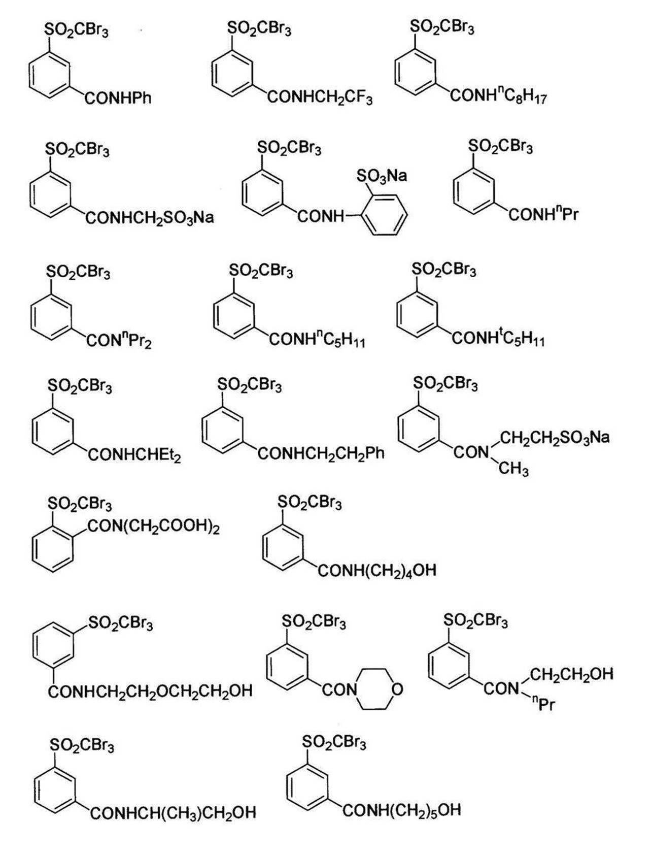


電子受容型重合開始剤の最低空軌道(LUMO)は、経時安定性、UV版飛び抑制性、GLV適性及びUV耐刷性の観点から、-3.3eVより大きいことが好ましく、-3.2eVより大きいことがより好ましい。
また、上限としては、感度の向上及び版飛びを発生しにくくする観点から、-3.00eV以下であることが好ましく、-3.02eV以下であることがより好ましい。
また、上限としては、感度の向上及び版飛びを発生しにくくする観点から、-3.00eV以下であることが好ましく、-3.02eV以下であることがより好ましい。
電子受容型重合開始剤は、1種単独で用いてもよく、2種以上を併用してもよい。
電子受容型重合開始剤の含有量は、画像記録層の全質量に対し、0.1質量%~50質量%であることが好ましく、0.5質量%~30質量%であることがより好ましく、0.8質量%~20質量%であることが特に好ましい。
また、画像記録層における電子受容型重合開始剤の含有量は、経時安定性、UV版飛び抑制性、GLV適性及びUV耐刷性の観点から、赤外線吸収剤の含有量よりも多いことが好ましく、赤外線吸収剤の含有量の1.5倍~5倍であることがより好ましく、赤外線吸収剤の含有量の2倍~4倍であることが特に好ましい。
電子受容型重合開始剤の含有量は、画像記録層の全質量に対し、0.1質量%~50質量%であることが好ましく、0.5質量%~30質量%であることがより好ましく、0.8質量%~20質量%であることが特に好ましい。
また、画像記録層における電子受容型重合開始剤の含有量は、経時安定性、UV版飛び抑制性、GLV適性及びUV耐刷性の観点から、赤外線吸収剤の含有量よりも多いことが好ましく、赤外線吸収剤の含有量の1.5倍~5倍であることがより好ましく、赤外線吸収剤の含有量の2倍~4倍であることが特に好ましい。
〔電子供与型重合開始剤(重合助剤)〕
本開示における画像記録層は、電子供与型重合開始剤(「重合助剤」ともいう)を含むことが好ましい。
電子供与型重合開始剤は、赤外線露光により赤外線吸収剤の電子が励起又は分子内移動した際に、赤外線吸収剤の一電子抜けた軌道に分子間電子移動で一電子を供与することにより、ラジカル等の重合開始種を発生する化合物である。
電子供与型重合開始剤としては、電子供与型ラジカル重合開始剤であることが好ましい。
本開示における画像記録層は、電子供与型重合開始剤(「重合助剤」ともいう)を含むことが好ましい。
電子供与型重合開始剤は、赤外線露光により赤外線吸収剤の電子が励起又は分子内移動した際に、赤外線吸収剤の一電子抜けた軌道に分子間電子移動で一電子を供与することにより、ラジカル等の重合開始種を発生する化合物である。
電子供与型重合開始剤としては、電子供与型ラジカル重合開始剤であることが好ましい。
画像記録層は、耐刷性の観点から、ボレート化合物を含有することが好ましく、ボレート化合物であることがより好ましい。
ボレート化合物としては、耐刷性及び視認性の観点から、テトラアリールボレート化合物、又は、モノアルキルトリアリールボレート化合物であることが好ましく、テトラアリールボレート化合物であることがより好ましい。
また、ボレート化合物としては、UV版飛び抑制性、耐刷性及び視認性の観点から、1つ以上の電子供与性基を有するテトラアリールボレート化合物であることが好ましく、1つの電子供与性基を各アリール基に有するテトラアリールボレート化合物であることがより好ましい。
上記電気供与性基としては、UV版飛び抑制性、耐刷性及び視認性の観点から、アルキル基、又は、アルコキシ基であることが好ましく、アルコキシ基であることがより好ましい。
ボレート化合物が有する対カチオンとしては、特に制限はないが、アルカリ金属イオン、又は、テトラアルキルアンモニウムイオンであることが好ましく、ナトリウムイオン、カリウムイオン、又は、テトラブチルアンモニウムイオンであることがより好ましい。
また、ボレート化合物が有する対カチオンとしては、本明細書に記載している赤外吸収剤において、カチオン性のポリメチン色素であってもよい。例えば、シアニン色素の対カチオンとして上記ボレート化合物を用いてもよい。
ボレート化合物として具体的には、ナトリウムテトラフェニルボレートが好ましく挙げられる。
以下に電子供与型重合開始剤の好ましい具体例として、B-1~B-9を示すが、これらに限定されないことは、言うまでもない。また、下記化学式において、Phはフェニル基を表し、Buはn-ブチル基を表す。

また、電子供与型重合開始剤の最高被占軌道(HOMO)は、感度の向上及び版飛びを発生しにくくする観点から、-6.00eV以上であることが好ましく、-5.95eV以上であることがより好ましく、-5.93eV以上であることが更に好ましく、-5.90eVより大きいことが特に好ましい。
また、上限としては、-5.00eV以下であることが好ましく、-5.40eV以下であることがより好ましい。
また、上限としては、-5.00eV以下であることが好ましく、-5.40eV以下であることがより好ましい。
電子供与型重合開始剤は、1種のみを用いてもよいし、2種以上を併用してもよい。
電子供与型重合開始剤の含有量としては、感度及び耐刷性の観点から、画像記録層の全質量に対し、0.01質量%~30質量%であることが好ましく、0.05質量%~25質量%であることがより好ましく、0.1質量%~20質量%であることが更に好ましい。
電子供与型重合開始剤の含有量としては、感度及び耐刷性の観点から、画像記録層の全質量に対し、0.01質量%~30質量%であることが好ましく、0.05質量%~25質量%であることがより好ましく、0.1質量%~20質量%であることが更に好ましい。
本開示において、重合開始剤は、電子供与型重合開始剤と電子受容型重合開始剤とが対塩を形成している化合物であってもよく、上記電子受容型重合開始剤及び上記電子供与型重合開始剤として、電子受容性重合開始剤構造を有するカチオンと電子供与型重合開始剤構造を有するアニオンとが塩を形成してなる化合物を含むことが好ましい。
例えば、本開示において、電子供与型重合開始剤におけるアニオンと電子受容型重合開始剤におけるカチオンとが対塩を形成してなる化合物であることが好ましく、オニウムカチオンとボレートアニオンとが対塩を形成してなる化合物であることがより好ましく、ヨードニウムカチオン又はスルホニウムカチオンとボレートアニオンとが対塩を形成してなる化合物であることが更に好ましく、ジアリールヨードニウムカチオン又はトリアリールスルホニウムカチオンとテトラアリールボレートアニオンとが対塩を形成してなる化合物であることが特に好ましい。
電子供与型重合開始剤におけるアニオン、及び、電子受容型重合開始剤におけるカチオンの好ましい態様としては、既述の電子供与型重合開始剤におけるアニオン及び既述の電子受容型重合開始剤におけるカチオンの好ましい態様と同様である。
画像記録層が、電子供与型重合開始剤であるアニオンと、電子受容型重合開始剤であるカチオンと、を含む場合(つまり、上記対塩を形成している化合物を含む場合)、画像記録層は電子受容型重合開始剤及び上記電子供与型重合開始剤を含むものとする。
また、電子供与型重合開始剤と電子受容型重合開始剤とが対塩を形成している化合物は、電子供与型重合開始剤として用いてもよいし、電子受容型重合開始剤として用いてもよい。
また、電子供与型重合開始剤と電子受容型重合開始剤とが対塩を形成してなる化合物は、既述の電子供与型重合開始剤と併用してもよいし、既述の電子受容型重合開始剤と併用してもよい。
〔赤外線吸収剤と電子供与型重合開始剤との関係〕
本開示における画像記録層は、上記赤外線吸収剤のHOMO-上記電子供与型重合開始剤のHOMOの値は、UV版飛び抑制性及び耐刷性の観点から、0.70eV以下であることが好ましく、0.60eV以下であることがより好ましく、0.55eV以下であることが更に好ましく、0.50eV以下であることが特に好ましく、0.50eV~-0.10eVであることが最も好ましい。
なお、マイナスの値は、上記電子供与型重合開始剤のHOMOが、上記赤外線吸収剤のHOMOよりも高くなることを意味する。
本開示における画像記録層は、上記赤外線吸収剤のHOMO-上記電子供与型重合開始剤のHOMOの値は、UV版飛び抑制性及び耐刷性の観点から、0.70eV以下であることが好ましく、0.60eV以下であることがより好ましく、0.55eV以下であることが更に好ましく、0.50eV以下であることが特に好ましく、0.50eV~-0.10eVであることが最も好ましい。
なお、マイナスの値は、上記電子供与型重合開始剤のHOMOが、上記赤外線吸収剤のHOMOよりも高くなることを意味する。
〔重合性化合物〕
本開示における画像記録層は、重合性化合物を含む。
本開示において、重合性化合物とは、重合性基を有する化合物をいう。
重合性基としては、特に限定されず公知の重合性基であればよいが、エチレン性不飽和基であることが好ましい。また、重合性基としては、ラジカル重合性基であってもカチオン重合性基であってもよいが、ラジカル重合性基であることが好ましい。
ラジカル重合性基としては、(メタ)アクリロイル基、アリル基、ビニルフェニル基、ビニル基等が挙げられ、反応性の観点から(メタ)アクリロイル基が好ましい。
重合性化合物の分子量(分子量分布を有する場合には、重量平均分子量)は、50以上2,500未満であることが好ましい。
本開示に用いられる重合性化合物は、例えば、ラジカル重合性化合物であっても、カチオン重合性化合物であってもよいが、少なくとも1個のエチレン性不飽和結合を有する付加重合性化合物(エチレン性不飽和化合物)であることが好ましい。
エチレン性不飽和化合物としては、末端エチレン性不飽和結合を少なくとも1個有する化合物であることが好ましく、末端エチレン性不飽和結合を2個以上有する化合物であることがより好ましい。重合性化合物は、例えばモノマー、プレポリマー、すなわち2量体、3量体若しくはオリゴマー、又は、それらの混合物などの化学的形態をもつ。
中でも、上記重合性化合物としては、UV耐刷性の観点から、3官能以上の重合性化合物を含むことが好ましく、7官能以上の重合性化合物を含むことがより好ましく、10官能以上の重合性化合物を含むことが更に好ましい。また、上記重合性化合物は、得られる平版印刷版におけるUV耐刷性の観点から、3官能以上(好ましくは7官能以上、より好ましくは10官能以上)のエチレン性不飽和化合物を含むことが好ましく、3官能以上(好ましくは7官能以上、より好ましくは10官能以上)の(メタ)アクリレート化合物を含むことが更に好ましい。
また、上記重合性化合物としては、機上現像性、及び、汚れ抑制性の観点から、2官能以下の重合性化合物を含むことが好ましく、2官能重合性化合物を含むことがより好ましく、2官能(メタ)アクリレート化合物を含むことが特に好ましい。
2官能以下の重合性化合物(好ましくは2官能重合性化合物)の含有量は、耐刷性、機上現像性、及び、汚れ抑制性の観点から、上記画像記録層における重合性化合物の全質量に対し、20質量%~100質量%であることが好ましく、5質量%~100質量%であることがより好ましく、50質量%~100質量%であることが特に好ましい。
2官能以下の重合性化合物(好ましくは2官能重合性化合物)の含有量は、耐刷性、機上現像性、及び、汚れ抑制性の観点から、上記画像記録層における重合性化合物の全質量に対し、20質量%~100質量%であることが好ましく、5質量%~100質量%であることがより好ましく、50質量%~100質量%であることが特に好ましい。
<<オリゴマー>>
画像記録層に含まれる重合性化合物としては、オリゴマーである重合性化合物(以下、単に「オリゴマー」ともいう。)を含有することが好ましい。
本開示においてオリゴマーとは、分子量(分子量分布を有する場合には、重量平均分子量)が600以上10,000以下であり、かつ、重合性基を少なくとも1つ含む重合性化合物を表す。
耐薬品性、UV耐刷性に優れる観点から、オリゴマーの分子量としては、1,000以上5,000以下であることが好ましい。
画像記録層に含まれる重合性化合物としては、オリゴマーである重合性化合物(以下、単に「オリゴマー」ともいう。)を含有することが好ましい。
本開示においてオリゴマーとは、分子量(分子量分布を有する場合には、重量平均分子量)が600以上10,000以下であり、かつ、重合性基を少なくとも1つ含む重合性化合物を表す。
耐薬品性、UV耐刷性に優れる観点から、オリゴマーの分子量としては、1,000以上5,000以下であることが好ましい。
また、UV耐刷性を向上させる観点から、1分子のオリゴマーにおける重合性基数は、2以上であることが好ましく、3以上であることがより好ましく、6以上であることが更に好ましく、10以上であることが特に好ましい。
また、オリゴマーにおける重合性基の上限値は、特に制限はないが、重合性基の数は20以下であることが好ましい。
また、オリゴマーにおける重合性基の上限値は、特に制限はないが、重合性基の数は20以下であることが好ましい。
UV耐刷性、及び、機上現像性の観点から、オリゴマーとしては、重合性基の数が7以上であり、かつ、分子量が1,000以上10,000以下であることが好ましく、重合性基の数が7以上20以下であり、かつ、分子量が1,000以上5,000以下であることがより好ましい。
なお、オリゴマーを製造する過程で生じる可能性のある、ポリマー成分を含有していてもよい。
なお、オリゴマーを製造する過程で生じる可能性のある、ポリマー成分を含有していてもよい。
UV耐刷性、視認性、及び、機上現像性の観点から、オリゴマーは、ウレタン結合を有する化合物、エステル結合を有する化合物及びエポキシ残基を有する化合物からなる群より選ばれる少なくとも1種を有することが好ましく、ウレタン結合を有する化合物を有することが好ましい。
本開示においてエポキシ残基とは、エポキシ基により形成される構造を指し、例えば酸基(カルボン酸基等)とエポキシ基との反応により得られる構造と同様の構造を意味する。
本開示においてエポキシ残基とは、エポキシ基により形成される構造を指し、例えば酸基(カルボン酸基等)とエポキシ基との反応により得られる構造と同様の構造を意味する。
オリゴマーの例であるウレタン結合を有する化合物としては、例えば、下記式(Ac-1)又は式(Ac-2)で表される基を少なくとも有する化合物であることが好ましく、下記式(Ac-1)で表される基を少なくとも有する化合物であることがより好ましい。

式(Ac-1)及び式(Ac-2)中、L1~L4はそれぞれ独立に、炭素数2~20の二価の炭化水素基を表し、波線部分は他の構造との結合位置を表す。
L1~L4としては、それぞれ独立に、炭素数2~20のアルキレン基であることが好ましく、炭素数2~10のアルキレン基であることがより好ましく、炭素数4~8のアルキレン基であることが更に好ましい。また、上記アルキレン基は、分岐又は環構造を有していてもよいが、直鎖アルキレン基であることが好ましい。
L1~L4としては、それぞれ独立に、炭素数2~20のアルキレン基であることが好ましく、炭素数2~10のアルキレン基であることがより好ましく、炭素数4~8のアルキレン基であることが更に好ましい。また、上記アルキレン基は、分岐又は環構造を有していてもよいが、直鎖アルキレン基であることが好ましい。
式(Ac-1)又は式(Ac-2)における波線部はそれぞれ独立に、下記式(Ae-1)又は式(Ae-2)で表される基における波線部と直接結合することが好ましい。

式(Ae-1)及び式(Ae-2)中、Rはそれぞれ独立に、アクリロイルオキシ基又はメタクリロイルオキシ基を表し、波線部分は式(Ac-1)及び式(Ac-2)における波線部との結合位置を表す。
また、ウレタン結合を有する化合物として、ポリイソシアネート化合物と、ポリオール化合物と、の反応により得られるポリウレタンに、高分子反応により重合性基を導入した化合物を用いてもよい。
例えば、酸基を有するポリオール化合物と、ポリイソシアネート化合物を反応させて得られたポリウレタンオリゴマーに、エポキシ基及び重合性基を有する化合物を反応させることにより、ウレタン結合を有する化合物を得てもよい。
例えば、酸基を有するポリオール化合物と、ポリイソシアネート化合物を反応させて得られたポリウレタンオリゴマーに、エポキシ基及び重合性基を有する化合物を反応させることにより、ウレタン結合を有する化合物を得てもよい。
オリゴマーの例であるエステル結合を有する化合物における重合性基の数は、3以上であることが好ましく、6以上であることが更に好ましい。
オリゴマーの例であるエポキシ残基を有する化合物としては、化合物内にヒドロキシ基を含む化合物が好ましい。
また、エポキシ残基を有する化合物における重合性基の数は、2~6であることが好ましく、2~3であることがより好ましい。
上記エポキシ残基を有する化合物としては、例えば、エポキシ基を有する化合物にアクリル酸を反応することにより得ることができる。
また、エポキシ残基を有する化合物における重合性基の数は、2~6であることが好ましく、2~3であることがより好ましい。
上記エポキシ残基を有する化合物としては、例えば、エポキシ基を有する化合物にアクリル酸を反応することにより得ることができる。
オリゴマーの具体例を下記表に示すが、本開示において用いられるオリゴマーはこれに限定されるものではない。
オリゴマーとしては、市販品を用いてもよく、UA510H、UA-306H、UA-306I、UA-306T(いずれも共栄社化学(株)製)、UV-1700B、UV-6300B、UV7620EA(いずれも日本合成化学工業(株)製)、U-15HA(新中村化学工業(株)製)、EBECRYL450、EBECRYL657、EBECRYL885、EBECRYL800、EBECRYL3416、EBECRYL860(いずれもダイセルオルネクス(株)製)等が挙げられるが、これに限定されるものではない。
オリゴマーとしては、市販品を用いてもよく、UA510H、UA-306H、UA-306I、UA-306T(いずれも共栄社化学(株)製)、UV-1700B、UV-6300B、UV7620EA(いずれも日本合成化学工業(株)製)、U-15HA(新中村化学工業(株)製)、EBECRYL450、EBECRYL657、EBECRYL885、EBECRYL800、EBECRYL3416、EBECRYL860(いずれもダイセルオルネクス(株)製)等が挙げられるが、これに限定されるものではない。
オリゴマーの含有量は、耐薬品性、UV耐刷性、及び機上現像カスの抑制性を向上させる観点から、画像記録層における重合性化合物の全質量に対し、30質量%~100質量%であることが好ましく、50質量%~100質量%であることがより好ましく、80質量%~100質量%であることが更に好ましい。
<<低分子重合性化合物>>
重合性化合物は、上記オリゴマー以外の重合性化合物を更に含んでいてもよい。
オリゴマー以外の重合性化合物としては、耐薬品性の観点から、低分子重合性化合物であることが好ましい。低分子重合性化合物としては、単量体、2量体、3量体又は、それらの混合物などの化学的形態であってもよい。
また、低分子重合性化合物としては、耐薬品性の観点から、エチレン性不飽和基を3つ以上有する重合性化合物、及びイソシアヌル環構造を有する重合性化合物からなる群より選ばれる少なくとも一方の重合性化合物であることが好ましい。
重合性化合物は、上記オリゴマー以外の重合性化合物を更に含んでいてもよい。
オリゴマー以外の重合性化合物としては、耐薬品性の観点から、低分子重合性化合物であることが好ましい。低分子重合性化合物としては、単量体、2量体、3量体又は、それらの混合物などの化学的形態であってもよい。
また、低分子重合性化合物としては、耐薬品性の観点から、エチレン性不飽和基を3つ以上有する重合性化合物、及びイソシアヌル環構造を有する重合性化合物からなる群より選ばれる少なくとも一方の重合性化合物であることが好ましい。
本開示において低分子重合性化合物とは、分子量(分子量分布を有する場合には、重量平均分子量)50以上600未満の重合性化合物を表す。
低分子重合性化合物の分子量としては、耐薬品性、UV耐刷性及び機上現像カスの抑制性に優れる観点から、100以上600未満であることが好ましく、300以上600未満であることがより好ましく、400以上600未満であることが更に好ましい。
低分子重合性化合物の分子量としては、耐薬品性、UV耐刷性及び機上現像カスの抑制性に優れる観点から、100以上600未満であることが好ましく、300以上600未満であることがより好ましく、400以上600未満であることが更に好ましい。
重合性化合物が、オリゴマー以外の重合性化合物として低分子重合性化合物を含む場合(2種以上の低分子重合性化合物を含む場合はその合計量)、耐薬品性、UV耐刷性及び機上現像カスの抑制性の観点から、上記オリゴマーと低分子重合性化合物との比(オリゴマー/低分子重合性化合物)は、質量基準で、10/1~1/10であることが好ましく、10/1~3/7であることがより好ましく、10/1~7/3であることが更に好ましい。
また、低分子重合性化合物としては、国際公開第2019/013268号の段落0082~0086に記載の重合性化合物も好適に用いることができる。
-特定化合物B2-
低分子重合性化合物としては、エチレン性不飽和基を1つ又は2つ有する化合物(以下、特定化合物B2ともいう。)を含んでいてもよい。
特定化合物B2が有するエチレン性不飽和基の好ましい態様は、特定化合物B1におけるエチレン性不飽和基と同様である。
また、特定化合物B2は、機上現像性の低下を抑制する観点から、エチレン性不飽和結合基を2つ有する化合物(即ち、2官能の重合性化合物)であることが好ましい。
低分子重合性化合物としては、エチレン性不飽和基を1つ又は2つ有する化合物(以下、特定化合物B2ともいう。)を含んでいてもよい。
特定化合物B2が有するエチレン性不飽和基の好ましい態様は、特定化合物B1におけるエチレン性不飽和基と同様である。
また、特定化合物B2は、機上現像性の低下を抑制する観点から、エチレン性不飽和結合基を2つ有する化合物(即ち、2官能の重合性化合物)であることが好ましい。
特定化合物B2としては、機上現像性及び耐刷性の観点から、メタクリレート化合物、即ち、メタクリロキシ基を有する化合物であることが好ましい。
特定化合物B2としては、機上現像性の観点から、アルキレンオキシ構造又はウレタン結合を含むことが好ましい。
特定化合物B2の分子量(分子量分布を有する場合には、重量平均分子量)としては、50以上1,000未満であることが好ましく、200~900であることがより好ましく、250~800であることが更に好ましい。
特定化合物B2の具体例を以下に挙げるが、本開示にて用いられる特定化合物B2はこれらに限定されるものではない。なお、下記(2)の化合物中、例えば、n+m=10である

特定化合物B2としては、以下に示す市販品を用いてもよいが、本開示にて用いられる特定化合物B2はこれらに限定されるものではない。
特定化合物B2の具体例としては、新中村化学工業(株)製のBPE-80N(上記(1)の化合物)、BPE-100、BPE-200、BPE-500、サートマー社製のCN104(上記(1)の化合物)等のエトキシ化ビスフェノールAジメタクリレートが挙げられる。
また、特定化合物B2の具体例としては、新中村化学工業(株)製のA-BPE-10(上記(2)の化合物)、A-BPE-4等のエトキシ化ビスフェノールAジアクリレートが挙げられる。
更に、特定化合物B2の具体例としては、AZ Electronics社製のFST 510等の2官能メタクリレートが挙げられる。
特定化合物B2の具体例としては、新中村化学工業(株)製のBPE-80N(上記(1)の化合物)、BPE-100、BPE-200、BPE-500、サートマー社製のCN104(上記(1)の化合物)等のエトキシ化ビスフェノールAジメタクリレートが挙げられる。
また、特定化合物B2の具体例としては、新中村化学工業(株)製のA-BPE-10(上記(2)の化合物)、A-BPE-4等のエトキシ化ビスフェノールAジアクリレートが挙げられる。
更に、特定化合物B2の具体例としては、AZ Electronics社製のFST 510等の2官能メタクリレートが挙げられる。
ここで、上記「FST 510」は、1モルの2,2,4-トリメチルヘキサメチレンジイソシアネートと2モルのヒドロキシエチルメタクリレートの反応生成物あって、上記(3)の化合物のメチルエチルケトン82質量%溶液である。
特定化合物B2の含有量は、機上現像性及び耐刷性の観点から、画像記録層の全質量に対して、1質量%~60質量%であることが好ましく、5質量%~55質量%であることがより好ましく、5質量%~50質量%であることが更に好ましい。
特定化合物B2を用いる場合、画像記録層における重合性化合物の全質量に対する上記特定化合物B2の含有量は、10質量%~100質量%であることが好ましく、50質量%~100質量%であることがより好ましく、80質量%~100質量%であることが更に好ましい。
特定化合物B2を用いる場合、画像記録層における重合性化合物の全質量に対する上記特定化合物B2の含有量は、10質量%~100質量%であることが好ましく、50質量%~100質量%であることがより好ましく、80質量%~100質量%であることが更に好ましい。
重合性化合物の構造、単独使用か併用か、添加量等の使用方法の詳細は、任意に設定できる。
中でも、画像記録層は、UV耐刷性の観点から、2種以上の重合性化合物を含むことが好ましい。
重合性化合物の含有量(重合性化合物を2種以上含む場合は、重合性化合物の総含有量)は、画像記録層の全質量に対して、5質量%~75質量%であることが好ましく、10質量%~70質量%であることがより好ましく、15質量%~60質量%であることが更に好ましい。
中でも、画像記録層は、UV耐刷性の観点から、2種以上の重合性化合物を含むことが好ましい。
重合性化合物の含有量(重合性化合物を2種以上含む場合は、重合性化合物の総含有量)は、画像記録層の全質量に対して、5質量%~75質量%であることが好ましく、10質量%~70質量%であることがより好ましく、15質量%~60質量%であることが更に好ましい。
〔粒子〕
本開示における画像記録層は、現像性、及び、UV耐刷性の観点から、粒子を含むことが好ましい。粒子としては、無機粒子であってもよいし、有機粒子であってもよい。
中でも、粒子として、有機粒子を含むことが好ましく、樹脂粒子を含むことがより好ましい。
無機粒子としては、公知の無機粒子を用いることができ、シリカ粒子、チタニア粒子等の金属酸化物粒子を好適に用いることができる。
本開示における画像記録層は、現像性、及び、UV耐刷性の観点から、粒子を含むことが好ましい。粒子としては、無機粒子であってもよいし、有機粒子であってもよい。
中でも、粒子として、有機粒子を含むことが好ましく、樹脂粒子を含むことがより好ましい。
無機粒子としては、公知の無機粒子を用いることができ、シリカ粒子、チタニア粒子等の金属酸化物粒子を好適に用いることができる。
<<樹脂粒子>>
樹脂粒子としては、例えば、付加重合型樹脂を含む粒子(即ち、付加重合型樹脂粒子)、重付加型樹脂を含む粒子(即ち、重付加型樹脂粒子)、重縮合型樹脂を含む粒子(即ち、重縮合型樹脂粒子)等が挙げられるが、中でも、付加重合型樹脂粒子、又は重付加型樹脂粒子が好ましい。
また、樹脂粒子としては、熱融着が可能となる観点から、熱可塑性樹脂を含む粒子(即ち、熱可塑性樹脂粒子)であってもよい。
樹脂粒子としては、例えば、付加重合型樹脂を含む粒子(即ち、付加重合型樹脂粒子)、重付加型樹脂を含む粒子(即ち、重付加型樹脂粒子)、重縮合型樹脂を含む粒子(即ち、重縮合型樹脂粒子)等が挙げられるが、中でも、付加重合型樹脂粒子、又は重付加型樹脂粒子が好ましい。
また、樹脂粒子としては、熱融着が可能となる観点から、熱可塑性樹脂を含む粒子(即ち、熱可塑性樹脂粒子)であってもよい。
また、樹脂粒子は、マイクロカプセル、ミクロゲル(即ち、架橋樹脂粒子)等の形態であってもよい。
樹脂粒子としては、熱可塑性樹脂粒子、熱反応性樹脂粒子、重合性基を有する樹脂粒子、疎水性化合物を内包しているマイクロカプセル、及び、ミクロゲル(架橋樹脂粒子)よりなる群から選ばれることが好ましい。中でも、重合性基を有する樹脂粒子が好ましい。
特に好ましい実施形態では、樹脂粒子は少なくとも1つのエチレン性不飽和基を含む。このような樹脂粒子の存在により、露光部の耐刷性及び未露光部の機上現像性を高める効果が得られる。
特に好ましい実施形態では、樹脂粒子は少なくとも1つのエチレン性不飽和基を含む。このような樹脂粒子の存在により、露光部の耐刷性及び未露光部の機上現像性を高める効果が得られる。
熱可塑性樹脂粒子としては、1992年1月のResearch Disclosure No.33303、特開平9-123387号公報、同9-131850号公報、同9-171249号公報、同9-171250号公報及び欧州特許第931647号明細書などに記載の熱可塑性樹脂粒子が好ましい。
熱可塑性樹脂粒子を構成する樹脂の具体例としては、エチレン、スチレン、塩化ビニル、アクリル酸メチル、アクリル酸エチル、メタクリル酸メチル、メタクリル酸エチル、塩化ビニリデン、アクリロニトリル、ビニルカルバゾール、ポリアルキレン構造を有するアクリレート又はメタクリレートなどのモノマーのホモポリマー若しくはコポリマー又はそれらの混合物を挙げることができる。
熱可塑性樹脂粒子としては、インク着肉性及びUV耐刷性の観点から、芳香族ビニル化合物により形成される構成単位、及び、ニトリル基を有する構成単位を有する樹脂を含むことが好ましい。
上記芳香族ビニル化合物としては、芳香環にビニル基が結合した構造を有する化合物であればよいが、スチレン化合物、ビニルナフタレン化合物等が挙げられ、スチレン化合物が好ましく、スチレンがより好ましい。
スチレン化合物としては、スチレン、p-メチルスチレン、p-メトキシスチレン、β-メチルスチレン、p-メチル-β-メチルスチレン、α-メチルスチレン、及びp-メトキシ-β-メチルスチレン等が挙げられ、スチレンが好ましく挙げられる。
スチレン化合物としては、スチレン、p-メチルスチレン、p-メトキシスチレン、β-メチルスチレン、p-メチル-β-メチルスチレン、α-メチルスチレン、及びp-メトキシ-β-メチルスチレン等が挙げられ、スチレンが好ましく挙げられる。
芳香族ビニル化合物により形成される構成単位の含有量は、インク着肉性の観点から、後述するニトリル基を有する構成単位の含有量よりも多いことが好ましく、熱可塑性樹脂の全質量に対し、15質量%~85質量%であることがより好ましく、30質量%~70質量%であることが更に好ましい。
ニトリル基を有する構成単位は、ニトリル基を有するモノマーを用いて導入されることが好ましい。
ニトリル基を有するモノマーとしては、アクリロニトリル化合物が挙げられ、(メタ)アクリロニトリルが好適に挙げられる。
ニトリル基を有する構成単位としては、(メタ)アクリロニトリルにより形成される構成単位が好ましい。
ニトリル基を有するモノマーとしては、アクリロニトリル化合物が挙げられ、(メタ)アクリロニトリルが好適に挙げられる。
ニトリル基を有する構成単位としては、(メタ)アクリロニトリルにより形成される構成単位が好ましい。
ニトリル基を有する構成単位の含有量は、インク着肉性の観点から、上記芳香族ビニル化合物により形成される構成単位の含有量よりも少ないことが好ましく、樹脂の全質量に対し、55質量%~90質量%であることがより好ましく、60質量%~85質量%であることがより好ましい。
また、熱可塑性樹脂粒子に含まれる樹脂が芳香族ビニル化合物により形成される構成単位及びニトリル基を有する構成単位を含む場合、芳香族ビニル化合物により形成される構成単位及びニトリル基を有する構成単位の含有量比(芳香族ビニル化合物により形成される構成単位:ニトリル基を有する構成単位)としては、質量基準で5:5~9:1であることが好ましく、より好ましくは、6:4~8:2である。
熱可塑性樹脂粒子に含まれる樹脂は、UV耐刷性及び耐薬品性の観点から、N-ビニル複素環化合物により形成される構成単位を更に有することが好ましい。
N-ビニル複素環化合物としては、例えば、N-ビニルピロリドン、N-ビニルカルバゾール、N-ビニルピロール、N-ビニルフェノチアジン、N-ビニルコハク酸イミド、N-ビニルフタルイミド、N-ビニルカプロラクタム、及びN-ビニルイミダゾールが挙げられ、N-ビニルピロリドンが好ましい。
N-ビニル複素環化合物としては、例えば、N-ビニルピロリドン、N-ビニルカルバゾール、N-ビニルピロール、N-ビニルフェノチアジン、N-ビニルコハク酸イミド、N-ビニルフタルイミド、N-ビニルカプロラクタム、及びN-ビニルイミダゾールが挙げられ、N-ビニルピロリドンが好ましい。
N-ビニル複素環化合物により形成される構成単位の含有量は、熱可塑性樹脂の全質量に対し、5質量%~50質量%であることが好ましく、10質量%~40質量%であることがより好ましい。
熱可塑性樹脂粒子に含まれる樹脂は、酸性基を有する構成単位を含有してもよいが、機上現像性及びインク着肉性の観点からは、酸性基を有する構成単位を含有しないことが好ましい。
具体的には、熱可塑性樹脂における酸性基を有する構成単位の含有量は、20質量%以下であることが好ましく、10質量%以下であることがより好ましく、5質量%以下であることが更に好ましい。上記含有量の下限は特に限定されず、0質量%であってもよい。
また、熱可塑性樹脂の酸価は、160mgKOH/g以下であることが好ましく、80mgKOH/g以下であることがより好ましく、40mgKOH/g以下であることが更に好ましい。上記酸価の下限は特に限定されず、0mgKOH/gであってもよい。
本開示において、酸価はJIS K0070:1992に準拠した測定法により求められる。
具体的には、熱可塑性樹脂における酸性基を有する構成単位の含有量は、20質量%以下であることが好ましく、10質量%以下であることがより好ましく、5質量%以下であることが更に好ましい。上記含有量の下限は特に限定されず、0質量%であってもよい。
また、熱可塑性樹脂の酸価は、160mgKOH/g以下であることが好ましく、80mgKOH/g以下であることがより好ましく、40mgKOH/g以下であることが更に好ましい。上記酸価の下限は特に限定されず、0mgKOH/gであってもよい。
本開示において、酸価はJIS K0070:1992に準拠した測定法により求められる。
熱可塑性樹脂粒子に含まれる樹脂は、インク着肉性の観点から、疎水性基を含む構成単位を含有してもよい。
上記疎水性基としては、アルキル基、アリール基、アラルキル基等が挙げられる。
疎水性基を含む構成単位としては、アルキル(メタ)アクリレート化合物、アリール(メタ)アクリレート化合物、又は、アラルキル(メタ)アクリレート化合物により形成される構成単位が好ましく、アルキル(メタ)アクリレート化合物により形成される構成単位がより好ましい。
上記疎水性基としては、アルキル基、アリール基、アラルキル基等が挙げられる。
疎水性基を含む構成単位としては、アルキル(メタ)アクリレート化合物、アリール(メタ)アクリレート化合物、又は、アラルキル(メタ)アクリレート化合物により形成される構成単位が好ましく、アルキル(メタ)アクリレート化合物により形成される構成単位がより好ましい。
熱可塑性樹脂粒子に含まれる樹脂における、疎水性基を有する構成単位の含有量は、樹脂の全質量に対し、5質量%~50質量%であることが好ましく、10質量%~30質量%であることがより好ましい。
熱可塑性樹脂粒子に含まれる熱可塑性樹脂は、UV耐刷性及び機上現像性の観点から、親水性基を有することが好ましい。
親水性基としては、親水性を有する構造であれば、特に制限はないが、カルボキシ基等の酸基、ヒドロキシ基、アミノ基、ニトリル基、ポリアルキレンオキシド構造等が挙げられる。
上記親水性基としては、UV耐刷性及び機上現像性の観点から、ポリアルキレンオキシド構造を有する基、ポリエステル構造を有する基、又は、スルホン酸基であることが好ましく、ポリアルキレンオキシド構造を有する基、又は、スルホン酸基であることがより好ましく、ポリアルキレンオキシド構造を有する基であることが更に好ましい。
親水性基としては、親水性を有する構造であれば、特に制限はないが、カルボキシ基等の酸基、ヒドロキシ基、アミノ基、ニトリル基、ポリアルキレンオキシド構造等が挙げられる。
上記親水性基としては、UV耐刷性及び機上現像性の観点から、ポリアルキレンオキシド構造を有する基、ポリエステル構造を有する基、又は、スルホン酸基であることが好ましく、ポリアルキレンオキシド構造を有する基、又は、スルホン酸基であることがより好ましく、ポリアルキレンオキシド構造を有する基であることが更に好ましい。
上記ポリアルキレンオキシド構造としては、機上現像性の観点から、ポリエチレンオキシド構造、ポリプロピレンオキシド構造、又は、ポリ(エチレンオキシド/プロピレンオキシド)構造であることが好ましい。
また、機上現像性の観点からは、上記親水性基の中でもポリアルキレンオキシド構造として、ポリプロピレンオキシド構造を有することが好ましく、ポリエチレンオキシド構造及びポリプロピレンオキシド構造を有することがより好ましい。
上記ポリアルキレンオキシド構造におけるアルキレンオキシド構造の数は、機上現像性の観点から、2以上であることが好ましく、5以上であることがより好ましく、5~200であることが更に好ましく、8~150であることが特に好ましい。
また、機上現像性の観点からは、上記親水性基の中でもポリアルキレンオキシド構造として、ポリプロピレンオキシド構造を有することが好ましく、ポリエチレンオキシド構造及びポリプロピレンオキシド構造を有することがより好ましい。
上記ポリアルキレンオキシド構造におけるアルキレンオキシド構造の数は、機上現像性の観点から、2以上であることが好ましく、5以上であることがより好ましく、5~200であることが更に好ましく、8~150であることが特に好ましい。
また、機上現像性の観点から、上記親水性基として、後述する式Zで表される基が好ましい。
熱可塑性樹脂が有する親水性基の中でも、下記式POにより表される基が好ましい。
熱可塑性樹脂が有する親水性基の中でも、下記式POにより表される基が好ましい。

式PO中、LPはそれぞれ独立に、アルキレン基を表し、RPは水素原子又はアルキル基を表し、nは1~100の整数を表す。
式PO中、LPはそれぞれ独立に、エチレン基、1-メチルエチレン基又は2-メチルエチレン基であることが好ましく、エチレン基であることがより好ましい。
式PO中、RPは水素原子又は炭素数1~18のアルキル基であることが好ましく、水素原子又は炭素数1~10のアルキル基であることがより好ましく、水素原子又は炭素数1~4のアルキル基であることが更に好ましく、水素原子又はメチル基であることが特に好ましい。
式PO中、nは1~10の整数が好ましく、1~4の整数がより好ましい。
式PO中、LPはそれぞれ独立に、エチレン基、1-メチルエチレン基又は2-メチルエチレン基であることが好ましく、エチレン基であることがより好ましい。
式PO中、RPは水素原子又は炭素数1~18のアルキル基であることが好ましく、水素原子又は炭素数1~10のアルキル基であることがより好ましく、水素原子又は炭素数1~4のアルキル基であることが更に好ましく、水素原子又はメチル基であることが特に好ましい。
式PO中、nは1~10の整数が好ましく、1~4の整数がより好ましい。
親水性基を有する構成単位の含有量は、樹脂の全質量に対し、5質量%~60質量%であることが好ましく、10質量%~30質量%であることがより好ましい。
熱可塑性樹脂粒子に含まれる樹脂は、その他の構成単位を更に含有してもよい。その他の構成単位としては、上述の各構成単位以外の構成単位を特に限定なく含有することができ、例えば、アクリルアミド化合物、ビニルエーテル化合物等により形成される構成単位が挙げられる。
熱可塑性樹脂粒子に含まれる樹脂における、その他の構成単位の含有量は、樹脂の全質量に対し、5質量%~50質量%であることが好ましく、10質量%~30質量%であることがより好ましい。
熱反応性樹脂粒子としては、熱反応性基を有する樹脂粒子が挙げられる。熱反応性樹脂粒子は熱反応による架橋及びその際の官能基変化により疎水化領域を形成する。
熱反応性基を有する樹脂粒子における熱反応性基としては、化学結合が形成されるならば、どのような反応を行う官能基でもよいが、重合性基であることが好ましく、その例として、ラジカル重合反応を行うエチレン性不飽和基(例えば、アクリロイル基、メタクリロイル基、ビニル基、アリル基など)、カチオン重合性基(例えば、ビニル基、ビニルオキシ基、エポキシ基、オキセタニル基など)、付加反応を行うイソシアナト基又はそのブロック体、エポキシ基、ビニルオキシ基及びこれらの反応相手である活性水素原子を有する官能基(例えば、アミノ基、ヒドロキシ基、カルボキシ基など)、縮合反応を行うカルボキシ基及び反応相手であるヒドロキシ基又はアミノ基、開環付加反応を行う酸無水物及び反応相手であるアミノ基又はヒドロキシ基などが好ましく挙げられる。
上記熱反応性基を有する樹脂としては、付加重合型樹脂、重付加型樹脂、又は重縮合型樹脂であってもよいし、熱可塑性樹脂であってもよい。
上記熱反応性基を有する樹脂としては、付加重合型樹脂、重付加型樹脂、又は重縮合型樹脂であってもよいし、熱可塑性樹脂であってもよい。
マイクロカプセルとしては、例えば、特開2001-277740号公報、特開2001-277742号公報に記載のごとく、画像記録層の構成成分の少なくとも一部(好ましくは疎水性化合物)を内包したものが好ましい。樹脂粒子としてマイクロカプセルを含有する画像記録層は、画像記録層の構成成分のうち疎水性成分(即ち、疎水性化合物)をマイクロカプセルに内包し、親水性成分(即ち、親水性化合物)をマイクロカプセル外に含有する構成が好ましい態様である。
ミクロゲル(架橋樹脂粒子)は、その表面又は内部の少なくとも一方に、画像記録層の構成成分の一部を含有することができる。特に、重合性基をその表面に有する反応性ミクロゲルは、平版印刷版原版の感度、及び、得られる平版印刷版の耐刷性の観点から好ましい。
画像記録層の構成成分を含むマイクロカプセルを得るためには、公知の合成法が適用できる。
ミクロゲル(架橋樹脂粒子)は、その表面又は内部の少なくとも一方に、画像記録層の構成成分の一部を含有することができる。特に、重合性基をその表面に有する反応性ミクロゲルは、平版印刷版原版の感度、及び、得られる平版印刷版の耐刷性の観点から好ましい。
画像記録層の構成成分を含むマイクロカプセルを得るためには、公知の合成法が適用できる。
ミクロゲル(架橋樹脂粒子)は、その表面又は内部の少なくとも一方に、画像記録層の構成成分の一部を含有することができる。特に、重合性基をその表面に有する反応性ミクロゲルは、平版印刷版原版の感度、及び、得られる平版印刷版の耐刷性の観点から好ましい。
画像記録層の構成成分を含むミクロゲルを得るためには、公知の合成法が適用できる。
画像記録層の構成成分を含むミクロゲルを得るためには、公知の合成法が適用できる。
樹脂粒子としては、得られる平版印刷版の耐刷性、耐汚れ性及び保存安定性の観点から、分子中に2個以上のヒドロキシ基を有する多価フェノール化合物とイソホロンジイソシアネートとの付加物である多価イソシアネート化合物、及び、活性水素を有する化合物の反応により得られる重付加型樹脂粒子が好ましい。
上記多価フェノール化合物としては、フェノール性ヒドロキシ基を有するベンゼン環を複数有している化合物が好ましい。
上記活性水素を有する化合物としては、ポリオール化合物、又は、ポリアミン化合物が好ましく、ポリオール化合物がより好ましく、プロピレングリコール、グリセリン及びトリメチロールプロパンよりなる群から選ばれた少なくとも1種の化合物が更に好ましい。また上記活性水素化合物としては、水を用いることができる。水を用いた場合、イソシアナト基と水との反応によって生じたアミンがウレア結合を形成し、粒子を形成することができる。
分子中に2個以上のヒドロキシ基を有する多価フェノール化合物とイソホロンジイソシアネートとの付加物である多価イソシアネート化合物、及び、活性水素を有する化合物の反応により得られる樹脂の粒子としては、国際公開第2018043259号の段落0230~0234に記載の樹脂粒子が好ましく挙げられる。
更に、樹脂粒子としては、得られる平版印刷版の耐刷性及び耐溶剤性の観点から、疎水性主鎖を有し、i)上記疎水性主鎖に直接的に結合されたニトリル基を有する構成ユニット、及び、ii)親水性ポリアルキレンオキシドセグメントを含むペンダント基を有する構成ユニットの両方を含む付加重合型樹脂粒子が好ましい。具体的には、特開2019-64269号公報の段落0156に記載の粒子が好ましい。
<<式Zで表される基>>
本開示における樹脂粒子は、親水性基として、下記式Zで表される基を有することが好ましい。
*-Q-W-Y 式Z
式Z中、Qは二価の連結基を表し、Wは親水性構造を有する二価の基又は疎水性構造を有する二価の基を表し、Yは親水性構造を有する一価の基又は疎水性構造を有する一価の基を表し、W及びYのいずれかは親水性構造を有し、*は他の構造との結合部位を表す。
また、式Z中に含まれる親水性構造のいずれかが、ポリアルキレンオキシド構造を含むことが好ましい。
本開示における樹脂粒子は、親水性基として、下記式Zで表される基を有することが好ましい。
*-Q-W-Y 式Z
式Z中、Qは二価の連結基を表し、Wは親水性構造を有する二価の基又は疎水性構造を有する二価の基を表し、Yは親水性構造を有する一価の基又は疎水性構造を有する一価の基を表し、W及びYのいずれかは親水性構造を有し、*は他の構造との結合部位を表す。
また、式Z中に含まれる親水性構造のいずれかが、ポリアルキレンオキシド構造を含むことが好ましい。
上記式ZにおけるQは、炭素数1~20の二価の連結基であることが好ましく、炭素数1~10の二価の連結基であることがより好ましい。
また、上記式ZにおけるQは、アルキレン基、アリーレン基、エステル結合、アミド結合、又は、これらを2以上組み合わせた基であることが好ましく、フェニレン基、エステル結合、又は、アミド結合であることがより好ましい。
また、上記式ZにおけるQは、アルキレン基、アリーレン基、エステル結合、アミド結合、又は、これらを2以上組み合わせた基であることが好ましく、フェニレン基、エステル結合、又は、アミド結合であることがより好ましい。
上記式ZのWにおける親水性構造を有する二価の基は、ポリアルキレンオキシド構造を含む基であることが好ましく、ポリアルキレンオキシ基、又は、ポリアルキレンオキシ基の一方の末端に-CH2CH2NRW-が結合した基であることが好ましい。なお、RWは、水素原子又はアルキル基を表す。
上記式ZのWにおける疎水性構造を有する二価の基は、-RWA-、-O-RWA-O-、-RWN-RWA-NRW-、-OC(=O)-RWA-O-、又は、-OC(=O)-RWA-O-であることが好ましい。なお、RWAはそれぞれ独立に、炭素数6~120の直鎖、分岐若しくは環状アルキレン基、炭素数6~120のハロアルキレン基、炭素数6~120のアリーレン基、炭素数6~120のアルカーリレン基(アルキルアリール基から水素原子を1つ除いた二価の基)、又は、炭素数6~120のアラルキレン基を表す。
上記式ZのWにおける疎水性構造を有する二価の基は、-RWA-、-O-RWA-O-、-RWN-RWA-NRW-、-OC(=O)-RWA-O-、又は、-OC(=O)-RWA-O-であることが好ましい。なお、RWAはそれぞれ独立に、炭素数6~120の直鎖、分岐若しくは環状アルキレン基、炭素数6~120のハロアルキレン基、炭素数6~120のアリーレン基、炭素数6~120のアルカーリレン基(アルキルアリール基から水素原子を1つ除いた二価の基)、又は、炭素数6~120のアラルキレン基を表す。
上記式ZのYにおける親水性構造を有する一価の基は、-OH、-C(=O)OH、末端が水素原子又はアルキル基であるポリアルキレンオキシ基、又は、末端が水素原子又はアルキル基であるポリアルキレンオキシ基の他方の末端に-CH2CH2N(RW)-が結合した基であることが好ましい。中でも、親水性構造を有する一価の基としては、ポリアルキレンオキシド構造を含む基であることが好ましく、末端が水素原子又はアルキル基であるポリアルキレンオキシ基、又は、末端が水素原子又はアルキル基であるポリアルキレンオキシ基の他方の末端に-CH2CH2N(RW)-が結合した基が好ましい。
上記式ZのYにおける疎水性構造を有する一価の基は、炭素数6~120の直鎖、分岐若しくは環状アルキル基、炭素数6~120のハロアルキル基、炭素数6~120のアリール基、炭素数6~120のアルカーリル基(アルキルアリール基)、炭素数6~120のアラルキル基、-ORWB、-C(=O)ORWB、又は、-OC(=O)RWBであることが好ましい。RWBは、炭素数6~20を有するアルキル基を表す。
上記式ZのYにおける疎水性構造を有する一価の基は、炭素数6~120の直鎖、分岐若しくは環状アルキル基、炭素数6~120のハロアルキル基、炭素数6~120のアリール基、炭素数6~120のアルカーリル基(アルキルアリール基)、炭素数6~120のアラルキル基、-ORWB、-C(=O)ORWB、又は、-OC(=O)RWBであることが好ましい。RWBは、炭素数6~20を有するアルキル基を表す。
上記式Zで表される基を有する樹脂粒子は、耐刷性、着肉性、及び、機上現像性の観点から、Wが親水性構造を有する二価の基であることがより好ましく、Qがフェニレン基、エステル結合、又は、アミド結合であり、Wは、ポリアルキレンオキシ基であり、Yが、末端が水素原子又はアルキル基であるポリアルキレンオキシ基であることがより好ましい。
なお、式Zで表される基は、樹脂粒子の分散性を高める分散性基として機能してもよい。
なお、式Zで表される基は、樹脂粒子の分散性を高める分散性基として機能してもよい。
本開示における樹脂粒子は、耐刷性、及び、機上現像性の観点から、重合性基(好ましくはエチレン性不飽和基)を有することが好ましく、特に、表面に重合性基を有する樹脂粒子を含むことがより好ましい。重合性基を有する樹脂粒子を用いることで、版飛び(好ましくはUV版飛び)を抑制しやすくなり、耐刷性(好ましくはUV耐刷性)も高められる。
本開示における樹脂粒子は、耐刷性の観点から、親水性基及び重合性基を有する樹脂粒子であることが好ましい。
上記重合性基は、カチオン重合性基であっても、ラジカル重合性基であってもよいが、反応性の観点からは、ラジカル重合性基であることが好ましい。
上記重合性基としては、重合可能な基であれば特に制限はないが、反応性の観点から、エチレン性不飽和基が好ましく、ビニルフェニル基(スチリル基)、(メタ)アクリロキシ基、又は、(メタ)アクリルアミド基がより好ましく、(メタ)アクリロキシ基が特に好ましい。
また、重合性基を有する樹脂粒子を構成する樹脂は、重合性基を有する構成単位を有することが好ましい。
なお、高分子反応により樹脂粒子の表面に重合性基を導入してもよい。
上記重合性基は、カチオン重合性基であっても、ラジカル重合性基であってもよいが、反応性の観点からは、ラジカル重合性基であることが好ましい。
上記重合性基としては、重合可能な基であれば特に制限はないが、反応性の観点から、エチレン性不飽和基が好ましく、ビニルフェニル基(スチリル基)、(メタ)アクリロキシ基、又は、(メタ)アクリルアミド基がより好ましく、(メタ)アクリロキシ基が特に好ましい。
また、重合性基を有する樹脂粒子を構成する樹脂は、重合性基を有する構成単位を有することが好ましい。
なお、高分子反応により樹脂粒子の表面に重合性基を導入してもよい。
また、樹脂粒子は、耐刷性、着肉性、機上現像性、及び、機上現像時の現像カス抑制性の観点から、ウレア結合を有する重付加型樹脂を含むことが好ましく、下記式(Iso)で表されるイソシアネート化合物と水とを少なくとも反応させて得られる構造を有する重付加型樹脂を含むことがより好ましく、下記式(Iso)で表されるイソシアネート化合物と水とを少なくとも反応させて得られる構造を有し、かつ、ポリオキシアルキレン構造として、ポリエチレンオキシド構造及びポリプロピレンオキシド構造を有する重付加型樹脂を含むことが特に好ましい。また、上記ウレア結合を有する重付加型樹脂を含む粒子は、ミクロゲルであることが好ましい。

式(Iso)中、nは0~10の整数を表す。
上記式(Iso)で表されるイソシアネート化合物と水との反応の一例としては、下記に示す反応が挙げられる。なお、下記の例は、n=0、4,4-異性体を使用した例である。
下記に示すように、上記式(Iso)で表されるイソシアネート化合物と水とを反応させると、水によりイソシアネート基の一部が加水分解し、アミノ基が生じ、生じたアミノ基とイソシアネート基とが反応し、ウレア結合が生成し、二量体が形成される。また、下記反応が繰り返され、ウレア結合を有する重付加型樹脂が形成される。
下記に示すように、上記式(Iso)で表されるイソシアネート化合物と水とを反応させると、水によりイソシアネート基の一部が加水分解し、アミノ基が生じ、生じたアミノ基とイソシアネート基とが反応し、ウレア結合が生成し、二量体が形成される。また、下記反応が繰り返され、ウレア結合を有する重付加型樹脂が形成される。
また、下記反応において、アルコール化合物、アミン化合物等のイソシアネート基と反応性を有する化合物(活性水素を有する化合物)を添加することにより、アルコール化合物、アミン化合物等の構造を、ウレア結合を有する重付加型樹脂に導入することもできる。
上記活性水素を有する化合物としては、既述の活性水素を有する化合物が好ましく挙げられる。
上記活性水素を有する化合物としては、既述の活性水素を有する化合物が好ましく挙げられる。

また、上記ウレア結合を有する重付加型樹脂は、エチレン性不飽和基を有することが好ましく、下記式(PETA)で表される基を有することがより好ましい。

式(PETA)中、波線部分は、他の構造との結合位置を表す。
<<樹脂粒子の合成>>
樹脂粒子の合成法としては、特に制限はなく、既述した各種の樹脂にて粒子を合成しうる方法であればよい。樹脂粒子の合成法としては、例えば、乳化重合法、懸濁重合法、分散重合法、ソープフリー重合法、マイクロエマルション重合法等の、公知の樹脂粒子の合成法が挙げられる。
その他、樹脂粒子の合成には、公知のマイクロカプセルの合成法、ミクロゲル(架橋樹脂粒子)の合成法等を用いてもよい。
樹脂粒子の合成法としては、特に制限はなく、既述した各種の樹脂にて粒子を合成しうる方法であればよい。樹脂粒子の合成法としては、例えば、乳化重合法、懸濁重合法、分散重合法、ソープフリー重合法、マイクロエマルション重合法等の、公知の樹脂粒子の合成法が挙げられる。
その他、樹脂粒子の合成には、公知のマイクロカプセルの合成法、ミクロゲル(架橋樹脂粒子)の合成法等を用いてもよい。
<<粒子の平均粒径>>
粒子の平均粒径は、0.01μm~3.0μmが好ましく、0.03μm~2.0μmがより好ましく、0.10μm~1.0μmが更に好ましい。この範囲で良好な解像度と経時安定性が得られる。
粒子の平均粒径は、光散乱法により測定するか、又は、粒子の電子顕微鏡写真を撮影し、写真上で粒子の粒径を総計で5,000個測定し、平均値を算出するものとする。なお、非球形粒子については写真上の粒子の円相当径とする。
なお、本開示における粒子の平均粒径は、特に断りのない限り、体積平均粒径であるものとする。
粒子の平均粒径は、0.01μm~3.0μmが好ましく、0.03μm~2.0μmがより好ましく、0.10μm~1.0μmが更に好ましい。この範囲で良好な解像度と経時安定性が得られる。
粒子の平均粒径は、光散乱法により測定するか、又は、粒子の電子顕微鏡写真を撮影し、写真上で粒子の粒径を総計で5,000個測定し、平均値を算出するものとする。なお、非球形粒子については写真上の粒子の円相当径とする。
なお、本開示における粒子の平均粒径は、特に断りのない限り、体積平均粒径であるものとする。
粒子(好ましくは樹脂粒子)は、1種のみを用いてもよいし、2種以上を併用してもよい。
粒子(好ましくは樹脂粒子)の含有量は、現像性、及び、耐刷性の観点から、画像記録層の全質量に対し、5質量%~90質量%が好ましく、10質量%~90質量%であることがより好ましく、20質量%~90質量%であることが更に好ましく、50質量%~90質量%であることが特に好ましい。
〔その他の成分〕
本開示における画像記録層は、既述の成分以外のその他の成分を含んでいてもよい。
その他の成分としては、バインダーポリマー、発色剤、連鎖移動剤、低分子親水性化合物、感脂化剤、その他の添加剤等が挙げられる。
本開示における画像記録層は、既述の成分以外のその他の成分を含んでいてもよい。
その他の成分としては、バインダーポリマー、発色剤、連鎖移動剤、低分子親水性化合物、感脂化剤、その他の添加剤等が挙げられる。
その他の成分としては、特開2009-255434号公報の段落0181~0190に開示される着色剤、焼き出し剤、重合禁止剤、高級脂肪酸誘導体、可塑剤、無機粒子、および、低分子親水性化合物等が挙げられる。
また、他の化合物としては、特開2012-187907号公報の段落0191~0217に開示される、疎水化前駆体(熱が加えられたときに画像記録層を疎水性に変換できる微粒子)、低分子親水性化合物、感脂化剤(例えば、ホスホニウム化合物、含窒素低分子化合物、アンモニウム基含有ポリマー)、及び、連鎖移動剤も挙げられる。
また、他の化合物としては、特開2012-187907号公報の段落0191~0217に開示される、疎水化前駆体(熱が加えられたときに画像記録層を疎水性に変換できる微粒子)、低分子親水性化合物、感脂化剤(例えば、ホスホニウム化合物、含窒素低分子化合物、アンモニウム基含有ポリマー)、及び、連鎖移動剤も挙げられる。
-バインダーポリマー-
画像記録層は、必要に応じて、バインダーポリマーを含んでいてもよい。
ここで、バインダーポリマーは、樹脂粒子以外のポリマー、すなわち、粒子形状でないポリマーを指す。
また、バインダーポリマーは、感脂化剤におけるアンモニウム塩含有ポリマー及び界面活性剤として用いるポリマーを除く。
画像記録層は、必要に応じて、バインダーポリマーを含んでいてもよい。
ここで、バインダーポリマーは、樹脂粒子以外のポリマー、すなわち、粒子形状でないポリマーを指す。
また、バインダーポリマーは、感脂化剤におけるアンモニウム塩含有ポリマー及び界面活性剤として用いるポリマーを除く。
バインダーポリマーは平版印刷版原版の画像記録層に用いられる公知のバインダーポリマー(例えば、(メタ)アクリル樹脂、ポリビニルアセタール、ポリウレタン樹脂等)を好適に使用することができる。
一例として、機上現像型平版印刷版原版に用いられるバインダーポリマー(以下、機上現像用バインダーポリマーともいう)について、詳細に記載する。
機上現像用バインダーポリマーとしては、アルキレンオキシド鎖を有するバインダーポリマーが好ましい。アルキレンオキシド鎖を有するバインダーポリマーは、ポリ(アルキレンオキシド)部位を主鎖に有していても側鎖に有していてもよい。また、ポリ(アルキレンオキシド)を側鎖に有するグラフトポリマーでも、ポリ(アルキレンオキシド)含有繰返し単位で構成されるブロックと(アルキレンオキシド)非含有繰返し単位で構成されるブロックとのブロックコポリマーでもよい。
ポリ(アルキレンオキシド)部位を主鎖に有する場合は、ポリウレタン樹脂が好ましい。
ポリ(アルキレンオキシド)部位を側鎖に有する場合の主鎖のポリマーとしては、(メタ)アクリル樹脂、ポリビニルアセタール樹脂、ポリウレタン樹脂、ポリウレア樹脂、ポリイミド樹脂、ポリアミド樹脂、エポキシ樹脂、ポリスチレン樹脂、ノボラック型フェノール樹脂、ポリエステル樹脂、合成ゴム、天然ゴムが挙げられ、特に(メタ)アクリル樹脂が好ましい。
また、バインダーポリマーの他の好ましい例として、6官能以上10官能以下の多官能チオールを核として、この核に対しスルフィド結合により結合したポリマー鎖を有し、上記ポリマー鎖が重合性基を有する高分子化合物(以下、星型高分子化合物ともいう。)が挙げられる。
星型高分子化合物としては、例えば、特開2012-148555号公報に記載の化合物を好ましく用いることができる。
星型高分子化合物としては、例えば、特開2012-148555号公報に記載の化合物を好ましく用いることができる。
星型高分子化合物は、特開2008-195018号公報に記載のような画像部の皮膜強度を向上するためのエチレン性不飽和結合等の重合性基を、主鎖又は側鎖、好ましくは側鎖に有しているものが挙げられる。星型高分子化合物が有する重合性基によって星型高分子化合物の分子間に架橋が形成され、硬化が促進する。
重合性基としては、(メタ)アクリル基、ビニル基、アリル基、ビニルフェニル基(スチリル基)などのエチレン性不飽和基、エポキシ基等が好ましく、(メタ)アクリル基、ビニル基、ビニルフェニル基(スチリル基)が重合反応性の観点でより好ましく、(メタ)アクリル基が特に好ましい。これらの基は、高分子反応、又は、共重合によってポリマーに導入することができる。具体的には、例えば、カルボキシ基を側鎖に有するポリマーとグリシジルメタクリレートとの反応、あるいはエポキシ基を有するポリマーとメタクリル酸などのエチレン性不飽和基含有カルボン酸との反応を利用できる。
重合性基としては、(メタ)アクリル基、ビニル基、アリル基、ビニルフェニル基(スチリル基)などのエチレン性不飽和基、エポキシ基等が好ましく、(メタ)アクリル基、ビニル基、ビニルフェニル基(スチリル基)が重合反応性の観点でより好ましく、(メタ)アクリル基が特に好ましい。これらの基は、高分子反応、又は、共重合によってポリマーに導入することができる。具体的には、例えば、カルボキシ基を側鎖に有するポリマーとグリシジルメタクリレートとの反応、あるいはエポキシ基を有するポリマーとメタクリル酸などのエチレン性不飽和基含有カルボン酸との反応を利用できる。
バインダーポリマーの分子量は、GPC法によるポリスチレン換算値として重量平均分子量(Mw)が、2,000以上であることが好ましく、5,000以上であることがより好ましく、10,000~300,000であることが更に好ましい。
バインダーポリマーとしては、必要に応じて、特開2008-195018号公報に記載のポリアクリル酸、ポリビニルアルコール、ポリビニルアセタールなどの親水性ポリマーを併用することができる。また、親油的なポリマーと親水的なポリマーとを併用することもできる。
中でも、画像記録層は、機上現像性の観点から、ポリビニルアセタールを含むことが好ましい。ポリビニルアセタールとしては、例えば、ポリビニルブチラール等が好適に挙げられる。
中でも、画像記録層は、機上現像性の観点から、ポリビニルアセタールを含むことが好ましい。ポリビニルアセタールとしては、例えば、ポリビニルブチラール等が好適に挙げられる。
ポリビニルアセタールは、ポリビニルアルコールのヒドロキシ基をアルデヒドにてアセタール化させて得られた樹脂である。
特に、ポリビニルアルコールのヒドロキシ基を、ブチルアルデヒドでアセタール化(即ち、ブチラール化)したポリビニルブチラールが好ましい。
ポリビニルアセタールは、ポリビニルアルコールのヒドロキシ基をアルデヒドにてアセタール化することで、下記(a)で表される構成単位を含むことが好ましい。
特に、ポリビニルアルコールのヒドロキシ基を、ブチルアルデヒドでアセタール化(即ち、ブチラール化)したポリビニルブチラールが好ましい。
ポリビニルアセタールは、ポリビニルアルコールのヒドロキシ基をアルデヒドにてアセタール化することで、下記(a)で表される構成単位を含むことが好ましい。

ここで、Rとしては、アセタール化に用いられたアルデヒドの残基を表す。
Rとしては、水素原子、アルキル基等の他、後述するエチレン性不飽和基が挙げられる。
Rとしては、水素原子、アルキル基等の他、後述するエチレン性不飽和基が挙げられる。
上記(a)で表される構成単位の含有量(上記(a)で表される構成単位に含まれる主鎖のエチレン基量ともいう。また、アセタール化度ともいう。)としては、ポリビニルアセタールの全構成単位(主鎖の全エチレン基量)に対して、50mol%~90mol%が好ましく、55mol%~85mol%がより好ましく、55mol%~80mol%が更に好ましい。
なお、アセタール化度とは、アセタール基が結合しているエチレン基量(上記(a)で表される構成単位に含まれる主鎖のエチレン基量)を、主鎖の全エチレン基量で除して求めたモル分率を百分率で示した値である。
また、後述のポリビニルアセタールの各構成単位の含有量においても、同様である。
なお、アセタール化度とは、アセタール基が結合しているエチレン基量(上記(a)で表される構成単位に含まれる主鎖のエチレン基量)を、主鎖の全エチレン基量で除して求めたモル分率を百分率で示した値である。
また、後述のポリビニルアセタールの各構成単位の含有量においても、同様である。
ポリビニルアセタールは、耐刷性向上の観点から、エチレン性不飽和基を有することが好ましい。
ここで、ポリビニルアセタールが有するエチレン性不飽和基としては特に制限はなく、反応性、機上現像性、及び耐刷性の観点から、ビニルフェニル基(スチリル基)、ビニルエステル基、ビニルエーテル基、アリル基、(メタ)アクリロキシ基、及び(メタ)アクリルアミド基からなる群より選ばれた少なくとも1種の基であることがより好ましく、ビニル基、アリル基、(メタ)アクリロキシ基等が好ましい。
ここで、ポリビニルアセタールが有するエチレン性不飽和基としては特に制限はなく、反応性、機上現像性、及び耐刷性の観点から、ビニルフェニル基(スチリル基)、ビニルエステル基、ビニルエーテル基、アリル基、(メタ)アクリロキシ基、及び(メタ)アクリルアミド基からなる群より選ばれた少なくとも1種の基であることがより好ましく、ビニル基、アリル基、(メタ)アクリロキシ基等が好ましい。
ポリビニルアセタールが、耐刷性向上の観点から、エチレン性不飽和基を有する構成単位を含むことが好ましい。
エチレン性不飽和基を有する構成単位としては、上述のアセタール環を有する構成単位であってもよいし、アセタール環を有する構成単位以外の構成単位であってもよい。
中でも、露光時の架橋密度増加の観点から、ポリビニルアセタールは、アセタール環にエチレン性不飽和基が導入された化合物であることが好ましい。即ち、上述の(a)で表される構成単位において、Rにエチレン性不飽和基を有することが好ましい。
エチレン性不飽和基を有する構成単位としては、上述のアセタール環を有する構成単位であってもよいし、アセタール環を有する構成単位以外の構成単位であってもよい。
中でも、露光時の架橋密度増加の観点から、ポリビニルアセタールは、アセタール環にエチレン性不飽和基が導入された化合物であることが好ましい。即ち、上述の(a)で表される構成単位において、Rにエチレン性不飽和基を有することが好ましい。
エチレン性不飽和基を有する構成単位が、アセタール環を有する構成単位以外の構成単位である場合、例えば、アクリレート基を有する構成単位、具体的には、下記(d)で表される構成単位であってもよい。

エチレン性不飽和基を有する構成単位がアセタール環を有する構成単位以外の構成単位である場合、この構成単位の含有量(アクリレート基量ともいう)としては、ポリビニルアセタールの全構成単位に対して、1mol%~15mol%が好ましく、1mol%~10mol%がより好ましい。
ポリビニルアセタールとしては、更に、機上現像性等の観点から、ヒドロキシ基を有する構成単位を含むことが好ましい。つまり、上記ポリビニルアセタールは、ビニルアルコールに由来する構成単位を含むことが好ましい。
ヒドロキシ基を有する構成単位としては、下記(b)で表される構成単位が挙げられる。
ヒドロキシ基を有する構成単位としては、下記(b)で表される構成単位が挙げられる。

上記(b)で表される構成単位の含有量(水酸基量ともいう)としては、機上現像性の観点から、ポリビニルアセタールの全構成単位に対して、5mol%~50mol%が好ましく、10mol%~40mol%がより好ましく、20mol%~40mol%が更に好ましい。
上記ポリビニルアセタールとしては、更に、その他の構成単位を含んでいてもよい。
その他の構成単位としては、例えば、アセチル基を有する構成単位、具体的には、以下(c)で表される構成単位が挙げられる。
その他の構成単位としては、例えば、アセチル基を有する構成単位、具体的には、以下(c)で表される構成単位が挙げられる。

上記(c)で表される構成単位の含有量(アセチル基量ともいう)としては、ポリビニルアセタールの全構成単位に対して、0.5mol%~10mol%が好ましく、0.5mol%~8mol%がより好ましく、1mol%~3mol%が更に好ましい。
ここで、上記アセタール化度、アクリレート基量、水酸基量、及びアセチル基量、は、以下のようにして求めることができる。
即ち、1H NMR測定によって、アセタールのメチル又はメチレン部位、アクリレート基のメチル部位、水酸基及びアセチル基のメチル部位のプロトンピーク面積比からmol含有率を算出する。
即ち、1H NMR測定によって、アセタールのメチル又はメチレン部位、アクリレート基のメチル部位、水酸基及びアセチル基のメチル部位のプロトンピーク面積比からmol含有率を算出する。
上記ポリビニルアセタールの重量平均分子量としては、18,000~150,000が好ましい。
上記ポリビニルアセタールの溶解度パラメータ(SP値ともいう)は、17.5MPa1/2~20.0MPa1/2であることが好ましく、18.0MPa1/2~19.5MPa1/2であることがより好ましい。
ここで、本開示における「溶解度パラメータ(単位:(MPa)1/2)」は、ハンセン(Hansen)溶解度パラメータを用いるものとする。
ハンセン(Hansen)溶解度パラメータは、ヒルデブランド(Hildebrand)によって導入された溶解度パラメータを、分散項δd、極性項δp、水素結合項δhの3成分に分割し、3次元空間に表したものであるが、本開示においては溶解度パラメータ(以降、SP値ともいう)をδ(単位:(MPa)1/2)で表し、下記式を用いて算出される値を用いる。
δ(MPa)1/2=(δd2+δp2+δh2)1/2
なお、この分散項δd、極性項δp、及び水素結合項δhは、ハンセンやその研究後継者らにより多く求められており、Polymer Handbook (fourth edition)、VII-698~711に詳しく掲載されている。また、ハンセンの溶解度パラメータの値の詳細については、Charles M.Hansen著の文献「Hansen Solubility Parameters; A Users Handbook (CRC Press,2007)」に記載されている。
本開示において、化合物の部分構造におけるハンセン溶解度パラメータは、コンピュータソフトウェア「Hansen Solubility Parameters in Practice(HSPiP ver.4.1.07)」を用いることにより、その化学構造から推算した値を用いることもできる。
また、本開示においては、化合物が付加重合型、重縮合型等のポリマーである場合は、モノマー単位ごとのSP値をモル分率で掛け合わせた総量で示し、化合物がモノマー単位を有しない低分子化合物である場合は、化合物全体のSP値とする。
なお、本開示において、ポリマーのSP値は、ポリマーの分子構造からPolymer Handbook (fourth edition)に記載のHoy法により計算してもよい。
上記ポリビニルアセタールの具体例[P-1~P-3]を以下に挙げるが、本開示に用いられるポリビニルアセタールはこれらに限定されるものではない。
下記構造中、「l」は50mol%~90mol%であり、「m」は0.5mol%~10質量%であり、「n」は5mol%~50mol%であり、「o」は1mol%~15mol%である。
下記構造中、「l」は50mol%~90mol%であり、「m」は0.5mol%~10質量%であり、「n」は5mol%~50mol%であり、「o」は1mol%~15mol%である。

上記ポリビニルアセタールとしては、市販品を用いることができる。
ポリビニルアセタールの市販品としては、積水化学工業(株)のエスレックシリーズ(具体的には、エスレック BX-L,BX-1,BX-5,BL-7Z,BM-1,BM-5,BH-6,BH-3等)が挙げられる。
ポリビニルアセタールの市販品としては、積水化学工業(株)のエスレックシリーズ(具体的には、エスレック BX-L,BX-1,BX-5,BL-7Z,BM-1,BM-5,BH-6,BH-3等)が挙げられる。
バインダーポリマーは、1種単独で用いてもよいし、2種以上を併用してもよい。
バインダーポリマーは、画像記録層中に任意な量で含有させることができるが、バインダーポリマーの含有量は、画像記録層の全質量に対して、1質量%~90質量%であることが好ましく、5質量%~80質量%であることがより好ましい。
-発色剤-
本開示における画像記録層は、発色剤を含むことが好ましく、酸発色剤を含むことがより好ましい。また、発色剤としては、ロイコ化合物を含むことが好ましい。
本開示で用いられる「発色剤」とは、光や酸等の刺激により発色又は消色し画像記録層の色を変化させる性質を有する化合物を意味し、また、「酸発色剤」とは、電子受容性化合物(例えば酸等のプロトン)を受容した状態で加熱することにより、発色又は消色し画像記録層の色を変化させる性質を有する化合物を意味する。酸発色剤としては、特に、ラクトン、ラクタム、サルトン、スピロピラン、エステル、アミド等の部分骨格を有し、電子受容性化合物と接触した時に、速やかにこれらの部分骨格が開環若しくは開裂する無色の化合物が好ましい。
このような酸発色剤の例としては、特開2019-18412号公報の0184~0191段落に記載された化合物が挙げられる。
中でも、本開示に用いられる発色剤は、視認性の観点から、スピロピラン化合物、スピロオキサジン化合物、スピロラクトン化合物、及び、スピロラクタム化合物よりなる群から選ばれた少なくとも1種の化合物であることが好ましい。
発色後の色素の色相としては、可視性の観点から、450~650nmの範囲に極大吸収を有することが好ましい。色味としては、赤、紫、青又は黒緑であることが好ましい。
発色後の色素の色相としては、可視性の観点から、450~650nmの範囲に極大吸収を有することが好ましい。色味としては、赤、紫、青又は黒緑であることが好ましい。
また、上記酸発色剤は、視認性、及び、露光部の視認性の観点から、ロイコ色素であることが好ましい。
上記ロイコ色素としては、ロイコ構造を有する色素であれば、特に制限はないが、スピロ構造を有することが好ましく、スピロラクトン環構造を有することがより好ましい。
また、上記ロイコ色素としては、視認性、及び、露光部の視認性の観点から、フタリド構造又はフルオラン構造を有するロイコ色素であることが好ましい。
更に、上記フタリド構造又はフルオラン構造を有するロイコ色素は、視認性、及び、露光部の視認性の観点から、下記式(Le-1)~式(Le-3)のいずれかで表される化合物であることが好ましく、下記式(Le-2)で表される化合物であることがより好ましい。
上記ロイコ色素としては、ロイコ構造を有する色素であれば、特に制限はないが、スピロ構造を有することが好ましく、スピロラクトン環構造を有することがより好ましい。
また、上記ロイコ色素としては、視認性、及び、露光部の視認性の観点から、フタリド構造又はフルオラン構造を有するロイコ色素であることが好ましい。
更に、上記フタリド構造又はフルオラン構造を有するロイコ色素は、視認性、及び、露光部の視認性の観点から、下記式(Le-1)~式(Le-3)のいずれかで表される化合物であることが好ましく、下記式(Le-2)で表される化合物であることがより好ましい。

式(Le-1)~式(Le-3)中、ERGはそれぞれ独立に、電子供与性基を表し、X1~X4はそれぞれ独立に、水素原子、ハロゲン原子又はジアルキルアニリノ基を表し、X5~X10はそれぞれ独立に、水素原子、ハロゲン原子又は一価の有機基を表し、Y1及びY2はそれぞれ独立に、C又はNを表し、Y1がNである場合は、X1は存在せず、Y2がNである場合は、X4は存在せず、Ra1は、水素原子、アルキル基又はアルコキシ基を表し、Rb1~Rb4はそれぞれ独立に、水素原子、アルキル基又はアリール基を表す。
式(Le-1)~式(Le-3)のERGにおける電子供与性基としては、視認性、及び、露光部の視認性の観点から、アミノ基、アルキルアミノ基、アリールアミノ基、ジアルキルアミノ基、モノアルキルモノアリールアミノ基、ジアリールアミノ基、アルコキシ基、アリーロキシ基、又は、アルキル基であることが好ましく、アミノ基、アルキルアミノ基、アリールアミノ基、ジアルキルアミノ基、モノアルキルモノアリールアミノ基、ジアリールアミノ基、アルコキシ基、又は、アリーロキシ基であることがより好ましく、アリールアミノ基、モノアルキルモノアリールアミノ基、又は、ジアリールアミノ基であることが更に好ましく、アリールアミノ基、又は、モノアルキルモノアリールアミノ基であることが特に好ましい。
式(Le-1)~式(Le-3)におけるX1~X4はそれぞれ独立に、視認性、及び、露光部の視認性の観点から、水素原子、又は、塩素原子であることが好ましく、水素原子であることがより好ましい。
式(Le-2)又は式(Le-3)におけるX5~X10はそれぞれ独立に、視認性、及び、露光部の視認性の観点から、水素原子、ハロゲン原子、アルキル基、アリール基、アミノ基、アルキルアミノ基、アリールアミノ基、ジアルキルアミノ基、モノアルキルモノアリールアミノ基、ジアリールアミノ基、ヒドロキシ基、アルコキシ基、アリーロキシ基、アシル基、アルコキシカルボニル基、アリーロキシカルボニル基又はシアノ基であることが好ましく、水素原子、ハロゲン原子、アルキル基、アリール基、アルコキシ基、又は、アリーロキシ基であることがより好ましく、水素原子、ハロゲン原子、アルキル基、又は、アリール基であることが更に好ましく、水素原子であることが特に好ましい。
式(Le-1)~式(Le-3)におけるY1及びY2は、視認性、及び、露光部の視認性の観点から、少なくとも1方がCであることが好ましく、Y1及びY2の両方がCであることがより好ましい。
式(Le-3)におけるRa1は、視認性、及び、露光部の視認性の観点から、アルキル基又はアルコキシ基であることが好ましく、アルコキシ基であることがより好ましく、メトキシ基であることが特に好ましい。
式(Le-1)におけるRb1~Rb4はそれぞれ独立に、視認性、及び、露光部の視認性の観点から、水素原子又はアルキル基であることが好ましく、アルキル基であることがより好ましく、メチル基であることが特に好ましい。
また、上記フタリド構造又はフルオラン構造を有するロイコ色素は、視認性、及び、露光部の視認性の観点から、上記フタリド構造又はフルオラン構造を有するロイコ色素は、下記式(Le-4)~式(Le-6)のいずれかで表される化合物であることがより好ましく、下記式(Le-5)で表される化合物であることが更に好ましい。

式(Le-4)~式(Le-6)中、ERGはそれぞれ独立に、電子供与性基を表し、X1~X4はそれぞれ独立に、水素原子、ハロゲン原子又はジアルキルアニリノ基を表し、Y1及びY2はそれぞれ独立に、C又はNを表し、Y1がNである場合は、X1は存在せず、Y2がNである場合は、X4は存在せず、Ra1は、水素原子、アルキル基又はアルコキシ基を表し、Rb1~Rb4はそれぞれ独立に、水素原子、アルキル基又はアリール基を表す。
式(Le-4)~式(Le-6)におけるERG、X1~X4、Y1、Y2、Ra1、及び、Rb1~Rb4はそれぞれ、式(Le-1)~式(Le-3)におけるERG、X1~X4、Y1、Y2、Ra1、及び、Rb1~Rb4と同義であり、好ましい態様も同様である。
更に、上記フタリド構造又はフルオラン構造を有するロイコ色素は、視認性、及び、露光部の視認性の観点から、上記フタリド構造又はフルオラン構造を有するロイコ色素は、下記式(Le-7)~式(Le-9)のいずれかで表される化合物であることが更に好ましく、下記式(Le-8)で表される化合物であることが特に好ましい。

式(Le-7)~式(Le-9)中、X1~X4はそれぞれ独立に、水素原子、ハロゲン原子又はジアルキルアニリノ基を表し、Y1及びY2はそれぞれ独立に、C又はNを表し、Y1がNである場合は、X1は存在せず、Y2がNである場合は、X4は存在せず、Ra1~Ra4はそれぞれ独立に、水素原子、アルキル基又はアルコキシ基を表し、Rb1~Rb4はそれぞれ独立に、水素原子、アルキル基又はアリール基を表し、Rc1及びRc2はそれぞれ独立に、アリール基を表す。
式(Le-7)~式(Le-9)におけるX1~X4、Y1及びY2は、式(Le-1)~式(Le-3)におけるX1~X4、Y1及びY2と同義であり、好ましい態様も同様である。
式(Le-7)におけるRa1~Ra4はそれぞれ独立に、視認性、及び、露光部の視認性の観点から、アルキル基又はアルコキシ基であることが好ましく、アルコキシ基であることがより好ましく、メトキシ基であることが特に好ましい。
式(Le-7)~式(Le-9)におけるRb1~Rb4はそれぞれ独立に、視認性、及び、露光部の視認性の観点から、水素原子、アルキル基、又は、アルキル基若しくはアルコキシ基が置換したアリール基であることが好ましく、水素原子、又は、アルキル基であることがより好ましく、水素原子、又は、メチル基であることが特に好ましい。
式(Le-8)におけるRc1及びRc2はそれぞれ独立に、視認性、及び、露光部の視認性の観点から、フェニル基、又は、アルキルフェニル基であることが好ましく、フェニル基であることがより好ましい。
また、式(Le-8)において、視認性、及び、露光部の視認性の観点から、X1~X4が水素原子であり、Y1及びY2がCであることが好ましい。
更に、式(Le-8)において、視認性、及び、露光部の視認性の観点から、Rb1及びRb2がそれぞれ独立に、水素原子、アルキル基、又は、アルキル基若しくはアルコキシ基が置換したアリール基であることが好ましく、水素原子、又は、アルキル基であることがより好ましい。
式(Le-1)~式(Le-9)におけるアルキル基は、直鎖であっても、分岐を有していても、環構造を有していてもよい。
また、式(Le-1)~式(Le-9)におけるアルキル基の炭素数は、1~20であることが好ましく、1~8であることがより好ましく、1~4であることが更に好ましく、1又は2であることが特に好ましい。
式(Le-1)~式(Le-9)におけるアリール基の炭素数は、6~20であることが好ましく、6~10であることがより好ましく、6~8であることが特に好ましい。
また、式(Le-1)~式(Le-9)におけるアルキル基の炭素数は、1~20であることが好ましく、1~8であることがより好ましく、1~4であることが更に好ましく、1又は2であることが特に好ましい。
式(Le-1)~式(Le-9)におけるアリール基の炭素数は、6~20であることが好ましく、6~10であることがより好ましく、6~8であることが特に好ましい。
また、式(Le-1)~式(Le-9)における一価の有機基、アルキル基、アリール基、ジアルキルアニリノ基、アルキルアミノ基、アルコキシ基等の各基は、置換基を有していてもよい。置換基としては、アルキル基、アリール基、ハロゲン原子、アミノ基、アルキルアミノ基、アリールアミノ基、ジアルキルアミノ基、モノアルキルモノアリールアミノ基、ジアリールアミノ基、ヒドロキシ基、アルコキシ基、アリーロキシ基、アシル基、アルコキシカルボニル基、アリーロキシカルボニル基、シアノ基等が挙げられる。また、これら置換基は、更にこれら置換基により置換されていてもよい。
好適に用いられる上記フタリド構造又はフルオラン構造を有するロイコ色素としては、以下の化合物が挙げられる。

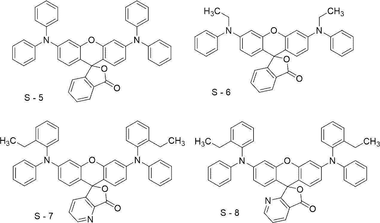
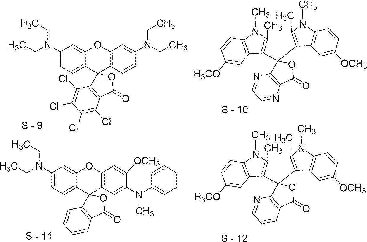

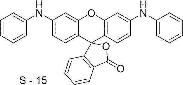
酸発色剤としては上市されている製品を使用することも可能であり、ETAC、RED500、RED520、CVL、S-205、BLACK305、BLACK400、BLACK100、BLACK500、H-7001、GREEN300、NIRBLACK78、BLUE220、H-3035、BLUE203、ATP、H-1046、H-2114(以上、福井山田化学工業(株)製)、ORANGE-DCF、Vermilion-DCF、PINK-DCF、RED-DCF、BLMB、CVL、GREEN-DCF、TH-107(以上、保土ヶ谷化学(株)製)、ODB、ODB-2、ODB-4、ODB-250、ODB-BlackXV、Blue-63、Blue-502、GN-169、GN-2、Green-118、Red-40、Red-8(以上、山本化成(株)製)、クリスタルバイオレットラクトン(東京化成工業(株)製)等が挙げられる。これらの市販品の中でも、ETAC、S-205、BLACK305、BLACK400、BLACK100、BLACK500、H-7001、GREEN300、NIRBLACK78、H-3035、ATP、H-1046、H-2114、GREEN-DCF、Blue-63、GN-169、クリスタルバイオレットラクトンが、形成される膜の可視光吸収率が良好のため好ましい。
好適に用いられるロイコ色素としては、視認性、及び、露光部の視認性の観点から、以下の化合物が挙げられる。

これらの発色剤は、1種単独で用いてもよいし、2種類以上の成分を組み合わせて使用することもできる。
発色剤の含有量は、画像記録層の全質量に対し、0.5質量%~10質量%であることが好ましく、1質量%~5質量%であることがより好ましい。
発色剤の含有量は、画像記録層の全質量に対し、0.5質量%~10質量%であることが好ましく、1質量%~5質量%であることがより好ましい。
-画像記録層の形成-
本開示に係る平版印刷版原版における画像記録層は、例えば、特開2008-195018号公報の段落0142~段落0143に記載のように、必要な上記各成分を公知の溶剤に分散又は溶解して塗布液を調製し、塗布液を支持体上にバーコーター塗布など公知の方法で塗布し、乾燥することにより形成することができる。塗布、乾燥後における画像記録層の塗布量(固形分)は、用途によって異なるが、0.3g/m2~3.0g/m2が好ましい。この範囲で、良好な感度と画像記録層の良好な皮膜特性が得られる。
溶剤としては、公知の溶剤を用いることができる。具体的には、例えば、水、アセトン、メチルエチルケトン(2-ブタノン)、シクロヘキサン、酢酸エチル、エチレンジクロライド、テトラヒドロフラン、トルエン、エチレングリコールモノメチルエーテル、エチレングリコールモノエチルエーテル、エチレングリコールジメチルエーテル、プロピレングリコールモノメチルエーテル、プロピレングリコールモノエチルエーテル、アセチルアセトン、シクロヘキサノン、ジアセトンアルコール、エチレングリコールモノメーチルエーテルアセテート、エチレングリコールエチルエーテルアセテート、エチレングリコールモノイソプロピルエーテル、エチレングリコールモノブチルエーテルアセテート、1-メトキシ-2-プロパノール、3-メトキシ-1-プロパノール、メトキシメトキシエタノール、ジエチレングリコールモノメチルエーテル、ジエチレングリコールモノエチルエーテル、ジエチレングリコールジメチルエーテル、ジエチレングリコールジエチルエーテル、プロピレングリコールモノメチルエーテルアセテート、プロピレングリコールモノエチルエーテルアセテート、3-メトキシプロピルアセテート、N,N-ジメチルホルムアミド、ジメチルスルホキシド、γ-ブチロラクトン、乳酸メチル、乳酸エチル等が挙げられる。溶剤は、1種単独で使用してもよいし、2種以上を併用してもよい。塗布液中の固形分濃度は1質量%~50質量%であることが好ましい。
塗布、乾燥後における画像記録層の塗布量(固形分)は、用途によって異なるが、良好な感度と画像記録層の良好な皮膜特性を得る観点から、0.3g/m2~3.0g/m2が好ましい。
また、本開示に係る平版印刷版原版における画像記録層の膜厚は、0.1μm~3.0μmであることが好ましく、0.3μm~2.0μmであることがより好ましい。
本開示において、平版印刷版原版における各層の膜厚は、平版印刷版原版の表面に対して垂直な方向に切断した切片を作製し、上記切片の断面を走査型顕微鏡(SEM)により観察することにより確認される。
<最外層>
本開示に係る機上現像型平版印刷版原版は、支持体と、画像記録層と、最外層とをこの順で有し、上記最外層が、変色性化合物を含む。
また、上記最外層は、機上現像型平版印刷版原版における支持体における画像記録層側の最外層である。
上記最外層は、酸素遮断により画像形成阻害反応を抑制する機能の他、画像記録層における傷の発生防止、高照度レーザー露光時のアブレーション防止等の機能を有していてもよい。
本開示に係る機上現像型平版印刷版原版は、支持体と、画像記録層と、最外層とをこの順で有し、上記最外層が、変色性化合物を含む。
また、上記最外層は、機上現像型平版印刷版原版における支持体における画像記録層側の最外層である。
上記最外層は、酸素遮断により画像形成阻害反応を抑制する機能の他、画像記録層における傷の発生防止、高照度レーザー露光時のアブレーション防止等の機能を有していてもよい。
-変色性化合物-
また、上記最外層は、変色性化合物を含む。
上記最外層は、変色性化合物以外に、水溶性ポリマー、疎水性ポリマー、感脂化剤、酸発生剤、赤外線吸収剤等の他の成分を含んでいてもよく、変色性化合物、及び、水溶性ポリマーを含むことが好ましく、変色性化合物、水溶性ポリマー、及び、疎水性ポリマーを含むことがより好ましい。
また、上記最外層は、変色性化合物を含む。
上記最外層は、変色性化合物以外に、水溶性ポリマー、疎水性ポリマー、感脂化剤、酸発生剤、赤外線吸収剤等の他の成分を含んでいてもよく、変色性化合物、及び、水溶性ポリマーを含むことが好ましく、変色性化合物、水溶性ポリマー、及び、疎水性ポリマーを含むことがより好ましい。
本開示に係る平版印刷版原版は、露光部の視認性を高める観点から、エネルギー密度110mJ/cm2にて波長830nmの赤外線による露光を行った場合の、露光前後の明度変化ΔLが、2.0以上であることが好ましく、3.0以上であることがより好ましく、5.0以上であることが更に好ましく、8.0以上であることが特に好ましく、10.0以上であることが最も好ましい。
明度変化ΔLの上限としては、例えば、20.0が挙げられる。
また、特に、変色性化合物を含む最外層を有する場合、上記明度変化ΔLの上記好ましい数値範囲を満たすことが好ましい。
明度変化ΔLの上限としては、例えば、20.0が挙げられる。
また、特に、変色性化合物を含む最外層を有する場合、上記明度変化ΔLの上記好ましい数値範囲を満たすことが好ましい。
明度変化ΔLの測定は、以下の方法により行う。
平版印刷版原版を、波長830nmの赤外線半導体レーザー搭載の富士フイルム グラフィックシステムズ(株)製Luxel PLATESETTER T-9800により、出力99.5%、外面ドラム回転数220rpm、解像度2,400dpi(dots per inch、1inch=25.4mm)の条件(エネルギー密度110mJ/cm2)で露光する。露光は25℃、50%RHの環境下で行う。
露光前後の平版印刷版原版の明度変化を測定する。
測定には、X-Rite社製分光測色計eXactを用いる。L*a*b*表色系のL*値(明度)を用い、露光部のL*値と露光前の露光部又は未露光部のL*値との差の絶対値を明度変化ΔLとする。
本開示において「変色性化合物」とは、赤外線露光に起因して、可視光領域(波長:400nm以上750nm未満)の吸収が変化する化合物をいう。つまり、本開示において「変色」とは、赤外線露光に起因して、可視光領域(波長:400nm以上750nm未満)の吸収が変化することをいう。
具体的には、本開示における変色性化合物は、(1)赤外線露光に起因して赤外線露光前より可視光領域の吸収が増加する化合物、(2)赤外線露光に起因して可視光領域の吸収を有するようになる化合物、(3)赤外線露光に起因して可視光領域に吸収を有しないようになる化合物が挙げられる。
なお、本開示における赤外線は、750nm~1mmの波長の光線であり、750nm~1,400nmの波長の光線であることが好ましい。
具体的には、本開示における変色性化合物は、(1)赤外線露光に起因して赤外線露光前より可視光領域の吸収が増加する化合物、(2)赤外線露光に起因して可視光領域の吸収を有するようになる化合物、(3)赤外線露光に起因して可視光領域に吸収を有しないようになる化合物が挙げられる。
なお、本開示における赤外線は、750nm~1mmの波長の光線であり、750nm~1,400nmの波長の光線であることが好ましい。
変色性化合物としては、赤外線露光に起因して発色する化合物を含むことが好ましい。
また、変色性化合物としては、赤外線露光に起因して分解する分解性化合物を含むことが好ましく、中でも、赤外線露光に起因する、熱、電子移動、又はその両方により分解する分解性化合物を含むことが好ましい。
より具体的に言えば、本開示における変色性化合物は、赤外線露光に起因して分解し(より好ましくは、赤外線露光に起因する、熱、電子移動、又はその両方により分解し)、赤外線露光前に比べて、可視光領域における吸収が増加するか、又は、吸収が短波長化し可視光領域に吸収を有するようになる化合物であることが好ましい。
ここで、「電子移動により分解する」とは、赤外線露光によって変色性化合物のHOMO(最高被占軌道)からLUMO(最低空軌道)に励起した電子が、分子内の電子受容基(LUMOと電位が近い基)に分子内電子移動し、それに伴って分解が生じることを意味する。
以下、変色性化合物の一例である分解性化合物について説明する。
分解性化合物は、赤外線波長域(750nm~1mmの波長域、好ましくは750nm~1,400nmの波長域)の少なくとも1部の光を吸収し、分解するものであればよいが、750nm~1,400nmの波長域に極大吸収を有する化合物であることが好ましい。
より具体的には、分解性化合物は、赤外線露光に起因して分解し、500nm~600nmの波長域に極大吸収波長を有する化合物を生成する化合物であることが好ましい。
分解性化合物は、赤外線波長域(750nm~1mmの波長域、好ましくは750nm~1,400nmの波長域)の少なくとも1部の光を吸収し、分解するものであればよいが、750nm~1,400nmの波長域に極大吸収を有する化合物であることが好ましい。
より具体的には、分解性化合物は、赤外線露光に起因して分解し、500nm~600nmの波長域に極大吸収波長を有する化合物を生成する化合物であることが好ましい。
分解性化合物は、露光部の視認性を高める観点から、赤外線露光により分解する基(具体的には、下記式1-1~式1-7におけるR1)を有する、シアニン色素であることが好ましい。
分解性化合物としては、露光部の視認性を高める観点から、下記式1-1で表される化合物であることがより好ましい。
分解性化合物としては、露光部の視認性を高める観点から、下記式1-1で表される化合物であることがより好ましい。

式1-1中、R1は下記式2-1~式4-1のいずれかで表される基を表し、R11~R18はそれぞれ独立に、水素原子、ハロゲン原子、-Ra、-ORb、-SRc、又は、-NRdReを表し、Ra~Reはそれぞれ独立に、炭化水素基を表し、A1、A2及び複数のR11~R18が連結して単環又は多環を形成してもよく、A1及びA2はそれぞれ独立に、酸素原子、硫黄原子、又は、窒素原子を表し、n11及びn12はそれぞれ独立に、0~5の整数を表し、但し、n11及びn12の合計は2以上であり、n13及びn14はそれぞれ独立に、0又は1を表し、Lは、酸素原子、硫黄原子、又は、-NR10-を表し、R10は、水素原子、アルキル基、又は、アリール基を表し、Zaは電荷を中和する対イオンを表す。

式2-1~式4-1中、R20、R30、R41及びR42はそれぞれ独立に、アルキル基又はアリール基を表し、Zbは電荷を中和する対イオンを表し、波線は、上記式1-1中のLで表される基との結合部位を表す。
式1-1で表される化合物は、赤外線で露光されると、R1-L結合が開裂し、Lは、=O、=S、又は=NR10となって、変色する。
式1-1において、R1は上記式2-1~式4-1のいずれかで表される基を表す。
以下、式2-1で表される基、式3-1で表される基、及び式4-1で表される基についてそれぞれ説明する。
以下、式2-1で表される基、式3-1で表される基、及び式4-1で表される基についてそれぞれ説明する。
式2-1中、R20は、アルキル基又はアリール基を表し、波線部分は、式1-1中のLで表される基との結合部位を表す。
R20で表されるアルキル基としては、炭素数1~30のアルキル基が好ましく、炭素数1~15のアルキル基がより好ましく、炭素数1~10のアルキル基が更に好ましい。
上記アルキル基は、直鎖状であっても、分岐を有していても、環構造を有していてもよい。
R20で表されるアリール基としては、炭素数6~30のアリール基が好ましく、炭素数6~20のアリール基がより好ましく、炭素数6~12のアリール基が更に好ましい。
R20としては、視認性の観点から、アルキル基であることが好ましい。
R20で表されるアルキル基としては、炭素数1~30のアルキル基が好ましく、炭素数1~15のアルキル基がより好ましく、炭素数1~10のアルキル基が更に好ましい。
上記アルキル基は、直鎖状であっても、分岐を有していても、環構造を有していてもよい。
R20で表されるアリール基としては、炭素数6~30のアリール基が好ましく、炭素数6~20のアリール基がより好ましく、炭素数6~12のアリール基が更に好ましい。
R20としては、視認性の観点から、アルキル基であることが好ましい。
また、分解性、及び、視認性の観点から、R20で表されるアルキル基としては、第二級アルキル基又は第三級アルキル基であることが好ましく、第三級アルキル基であることが好ましい。
更に、分解性、及び、視認性の観点から、R20で表されるアルキル基としては、炭素数1~8のアルキル基であることが好ましく、炭素数3~10の分岐状のアルキル基であることがより好ましく、炭素数3~6の分岐状のアルキル基であることが更に好ましく、イソプロピル基、又はtert-ブチル基が特に好ましく、tert-ブチル基が最も好ましい。
更に、分解性、及び、視認性の観点から、R20で表されるアルキル基としては、炭素数1~8のアルキル基であることが好ましく、炭素数3~10の分岐状のアルキル基であることがより好ましく、炭素数3~6の分岐状のアルキル基であることが更に好ましく、イソプロピル基、又はtert-ブチル基が特に好ましく、tert-ブチル基が最も好ましい。
以下に、上記式2-1で表される基の具体例を挙げるが、本開示はこれらに限定されるものではない。下記構造式中、●は式1-1中のLで表される基との結合部位を表す。

式3-1中、R30は、アルキル基又はアリール基を表し、波線部分は、式1-1中のLで表される基との結合部位を表す。
R30で表されるアルキル基及びアリール基としては、式2-1中のR20で表されるアルキル基及びアリール基と同様であり、好ましい態様も同様である。
R30で表されるアルキル基及びアリール基としては、式2-1中のR20で表されるアルキル基及びアリール基と同様であり、好ましい態様も同様である。
分解性、及び、視認性の観点から、R30で表されるアルキル基としては、第二級アルキル基又は第三級アルキル基であることが好ましく、第三級アルキル基であることが好ましい。
また、分解性、及び、視認性の観点から、R30で表されるアルキル基としては、炭素数1~8のアルキル基であることが好ましく、炭素数3~10の分岐状のアルキル基であることがより好ましく、炭素数3~6の分岐状のアルキル基であることが更に好ましく、イソプロピル基、又はtert-ブチル基が特に好ましく、tert-ブチル基が最も好ましい。
更に、分解性、及び、視認性の観点から、R30で表されるアルキル基は、置換アルキル基であることが好ましく、フルオロ置換アルキル基であることがより好ましく、パーフルオロアルキル基であることが更に好ましく、トリフルオロメチル基であることが特に好ましい。
また、分解性、及び、視認性の観点から、R30で表されるアルキル基としては、炭素数1~8のアルキル基であることが好ましく、炭素数3~10の分岐状のアルキル基であることがより好ましく、炭素数3~6の分岐状のアルキル基であることが更に好ましく、イソプロピル基、又はtert-ブチル基が特に好ましく、tert-ブチル基が最も好ましい。
更に、分解性、及び、視認性の観点から、R30で表されるアルキル基は、置換アルキル基であることが好ましく、フルオロ置換アルキル基であることがより好ましく、パーフルオロアルキル基であることが更に好ましく、トリフルオロメチル基であることが特に好ましい。
分解性、及び、視認性の観点から、R30で表されるアリール基は置換アリール基であることが好ましく、置換基としては、アルキル基(好ましくは炭素数1~4のアルキル基)、アルコキシ基(好ましくは炭素数1~4のアルコキシ基)等が挙げられる。
以下に、上記式3-1で表される基の具体例を挙げるが、本開示はこれらに限定されるものではない。下記構造式中、●は式1-1中のLで表される基との結合部位を表す。

式4-1中、R41及びR42はそれぞれ独立に、アルキル基又はアリール基を表し、Zbは電荷を中和する対イオンを表し、波線部分は、式1-1中のLで表される基との結合部位を表す。
R41又はR42で表されるアルキル基及びアリール基としては、式2中のR20で表されるアルキル基及びアリール基と同様であり、好ましい態様も同様である。
R41としては、分解性、及び、視認性の観点から、アルキル基であることが好ましい。
R42としては、分解性、及び、視認性の観点から、アルキル基であることが好ましい。
R41又はR42で表されるアルキル基及びアリール基としては、式2中のR20で表されるアルキル基及びアリール基と同様であり、好ましい態様も同様である。
R41としては、分解性、及び、視認性の観点から、アルキル基であることが好ましい。
R42としては、分解性、及び、視認性の観点から、アルキル基であることが好ましい。
分解性、及び、視認性の観点から、R41で表されるアルキル基としては、炭素数1~8のアルキル基であることが好ましく、炭素数1~4のアルキル基であることがより好ましく、メチル基が特に好ましい。
分解性、及び、視認性の観点から、R42で表されるアルキル基としては、第二級アルキル基又は第三級アルキル基であることが好ましく、第三級アルキル基であることが好ましい。
また、分解性、及び、視認性の観点から、R42で表されるアルキル基としては、炭素数1~8のアルキル基であることが好ましく、炭素数3~10の分岐状のアルキル基であることがより好ましく、炭素数3~6の分岐状のアルキル基であることが更に好ましく、イソプロピル基、又は、tert-ブチル基が特に好ましく、tert-ブチル基が最も好ましい。
分解性、及び、視認性の観点から、R42で表されるアルキル基としては、第二級アルキル基又は第三級アルキル基であることが好ましく、第三級アルキル基であることが好ましい。
また、分解性、及び、視認性の観点から、R42で表されるアルキル基としては、炭素数1~8のアルキル基であることが好ましく、炭素数3~10の分岐状のアルキル基であることがより好ましく、炭素数3~6の分岐状のアルキル基であることが更に好ましく、イソプロピル基、又は、tert-ブチル基が特に好ましく、tert-ブチル基が最も好ましい。
式4-1におけるZbは、電荷を中和するための対イオンであればよく、化合物全体として、式1-1におけるZaに含まれてもよい。
Zbは、スルホネートイオン、カルボキシレートイオン、テトラフルオロボレートイオン、ヘキサフルオロホスフェートイオン、p-トルエンスルホネートイオン、又は過塩素酸塩イオンが好ましく、テトラフルオロボレートイオンがより好ましい。
Zbは、スルホネートイオン、カルボキシレートイオン、テトラフルオロボレートイオン、ヘキサフルオロホスフェートイオン、p-トルエンスルホネートイオン、又は過塩素酸塩イオンが好ましく、テトラフルオロボレートイオンがより好ましい。
以下に、上記式4-1で表される基の具体例を挙げるが、本開示はこれらに限定されるものではない。下記構造式中、●は式1-1中のLで表される基との結合部位を表す。

式1-1において、Lは、酸素原子、又は-NR10-が好ましく、酸素原子が特に好ましい。
また、-NR10-におけるR10は、アルキル基が好ましい。R10で表されるアルキル基としては、炭素数1~10のアルキル基が好ましい。また、R10で表されるアルキル基は、直鎖状であっても、分岐を有していても、環構造を有していてもよい。
アルキル基の中では、メチル基又はシクロヘキシル基が好ましい。
-NR10-におけるR10がアリール基の場合、炭素数6~30のアリール基が好ましく、炭素数6~20のアリール基がより好ましく、炭素数6~12のアリール基が更に好ましい。また、これらアリール基は、置換基を有していてもよい。
また、-NR10-におけるR10は、アルキル基が好ましい。R10で表されるアルキル基としては、炭素数1~10のアルキル基が好ましい。また、R10で表されるアルキル基は、直鎖状であっても、分岐を有していても、環構造を有していてもよい。
アルキル基の中では、メチル基又はシクロヘキシル基が好ましい。
-NR10-におけるR10がアリール基の場合、炭素数6~30のアリール基が好ましく、炭素数6~20のアリール基がより好ましく、炭素数6~12のアリール基が更に好ましい。また、これらアリール基は、置換基を有していてもよい。
式1-1において、R11~R18は、それぞれ独立に、水素原子、-Ra、-ORb、-SRc、又は-NRdReであることが好ましい。
Ra~Reで表される炭化水素基は、炭素数1~30の炭化水素基が好ましく、炭素数1~15の炭化水素基がより好ましく、炭素数1~10の炭化水素基が更に好ましい。
上記炭化水素基は、直鎖状であっても、分岐を有していても、環構造を有していてもよい。
上記炭化水素基としては、アルキル基が特に好ましい。
Ra~Reで表される炭化水素基は、炭素数1~30の炭化水素基が好ましく、炭素数1~15の炭化水素基がより好ましく、炭素数1~10の炭化水素基が更に好ましい。
上記炭化水素基は、直鎖状であっても、分岐を有していても、環構造を有していてもよい。
上記炭化水素基としては、アルキル基が特に好ましい。
上記アルキル基としては、炭素数1~30のアルキル基が好ましく、炭素数1~15のアルキル基がより好ましく、炭素数1~10のアルキル基が更に好ましい。
上記アルキル基は、直鎖状であっても、分岐を有していても、環構造を有していてもよい。
具体的には、例えば、メチル基、エチル基、プロピル基、ブチル基、ペンチル基、ヘキシル基、ヘプチル基、オクチル基、ノニル基、デシル基、ウンデシル基、ドデシル基、トリデシル基、ヘキサデシル基、オクタデシル基、エイコシル基、イソプロピル基、イソブチル基、s-ブチル基、tert-ブチル基、イソペンチル基、ネオペンチル基、1-メチルブチル基、イソヘキシル基、2-エチルヘキシル基、2-メチルヘキシル基、シクロヘキシル基、シクロペンチル基、及び、2-ノルボルニル基が挙げられる。
アルキル基の中で、メチル基、エチル基、プロピル基又はブチル基が好ましい。
上記アルキル基は、置換基を有していてもよい。
置換基の例としては、アルコキシ基、アリーロキシ基、アミノ基、アルキルチオ基、アリールチオ基、ハロゲン原子、カルボキシ基、カルボキシレート基、スルホ基、スルホネート基、アルキルオキシカルボニル基、アリールオキシカルボニル基、及びこれらを組み合わせた基等が挙げられる。
置換基の例としては、アルコキシ基、アリーロキシ基、アミノ基、アルキルチオ基、アリールチオ基、ハロゲン原子、カルボキシ基、カルボキシレート基、スルホ基、スルホネート基、アルキルオキシカルボニル基、アリールオキシカルボニル基、及びこれらを組み合わせた基等が挙げられる。
式1-1におけるR11~R14はそれぞれ独立に、水素原子、又は、-Ra(即ち炭化水素基)であることが好ましく、水素原子、又は、アルキル基であることがより好ましく、以下の場合を除き、水素原子であることが更に好ましい。
中でも、Lが結合する炭素原子と結合する炭素原子に結合するR11及びR13は、アルキル基が好ましく、両者が連結して環を形成することがより好ましい。上記形成される環としては、単環であってもよく、多環であってもよい。形成される環として、具体的には、シクロペンテン環、シクロペンタジエン環、シクロヘキセン環、シクロヘキサジエン環等の単環、及び、インデン環、インドール環等の多環が挙げられる。
また、A1 +が結合する炭素原子に結合するR12はR15又はR16(好ましくはR16)と連結して環を形成することが好ましく、A2が結合する炭素原子に結合するR14はR17又はR18(好ましくはR18)と連結して環を形成することが好ましい。
式1-1において、n13は1であり、R16は、-Ra(即ち炭化水素基)であることが好ましい。
また、R16は、A1 +が結合する炭素原子に結合するR12と連結して環を形成することが好ましい。形成される環としては、インドリウム環、ピリリウム環、チオピリリウム環、ベンゾオキサゾリン環、又はベンゾイミダゾリン環が好ましく、露光部の視認性を高める観点から、インドリウム環がより好ましい。これらの環は更に置換基を有していてもよい。
式1-1において、n14は1であり、R18は、-Ra(即ち炭化水素基)であることが好ましい。
また、R18は、A2が結合する炭素原子に結合するR14と連結して環を形成することが好ましい。形成される環としては、インドール環、ピラン環、チオピラン環、ベンゾオキサゾール環、又はベンゾイミダゾール環が好ましく、露光部の視認性を高める観点から、インドール環がより好ましい。これらの環は更に置換基を有していてもよい。
式1-1におけるR16及びR18は同一の基であることが好ましく、それぞれが環を形成する場合、A1 +及びA2を除き、同一の構造の環を形成することが好ましい。
式1-1におけるR15及びR17は同一の基であることが好ましい。また、R15及びR17は、-Ra(即ち炭化水素基)であることが好ましく、アルキル基であることがより好ましく、置換アルキル基であることが更に好ましい。
式1-1により表される化合物において、水溶性を向上させる観点からは、R15及びR17は置換基アルキル基であることが好ましい。
R15又はR17で表される置換アルキル基としては、下記式(a1)~式(a4)のいずれかで表される基が挙げられる。
R15又はR17で表される置換アルキル基としては、下記式(a1)~式(a4)のいずれかで表される基が挙げられる。

式(a1)~式(a4)中、RW0は炭素数2~6のアルキレン基を表し、Wは単結合又は酸素原子を表し、nW1は1~45の整数を表し、RW1は炭素数1~12のアルキル基又は-C(=O)-RW5を表し、RW5は炭素数1~12のアルキル基を表し、RW2~RW4はそれぞれ独立に、単結合又は炭素数1~12のアルキレン基を表し、Mは水素原子、ナトリウム原子、カリウム原子、又は、オニウム基を表す。
式(a1)において、RW0で表されるアルキレン基の具体例としては、エチレン基、n-プロピレン基、イソプロピレン基、n-ブチレン基、イソブチレン基、n-ペンチレン基、イソペンチレン基、n-ヘキシル基、イソヘキシル基等が挙げられ、エチレン基、n-プロピレン基、イソプロピレン基、又はn-ブチレン基が好ましく、n-プロピレン基が特に好ましい。
nW1は1~10が好ましく、1~5がより好ましく、1~3が特に好ましい。
RW1で表されるアルキル基の具体例としては、メチル基、エチル基、n-プロピル基、イソプロピル基、n-ブチル基、イソブチル基、tert-ブチル基、n-ペンチル基、イソペンチル基、ネオペンチル基、n-ヘキシル基、n-オクチル基、n-ドデシル基等が挙げられ、メチル基、エチル基、n-プロピル基、イソプロピル基、又はn-ブチル基、tert-ブチル基が好ましく、メチル基、又はエチル基が更に好ましく、メチル基が特に好ましい。
RW5で表されるアルキル基は、RW1で表されるアルキル基と同様であり、好ましい態様もRW1で表されるアルキル基の好ましい態様と同様である。
式(a1)で表される基の具体例を以下に示すが、本開示はこれらに限定されるものではない。下記構造式中、Meはメチル基、Etはエチル基を表し、*は結合部位を表す。

式(a2)~式(a4)において、RW2~RW4で表されるアルキレン基の具体例としては、メチレン基、エチレン基、n-プロピレン基、イソプロピレン基、n-ブチレン基、イソブチレン基、n-ペンチレン基、イソペンチレン基、n-ヘキシル基、イソヘキシル基、n-オクチレン基、n-ドデシレン基等が挙げられ、エチレン基、n-プロピレン基、イソプロピレン基、又は、n-ブチレン基が好ましく、エチレン基、又は、n-プロピレン基が特に好ましい。
式(a3)において、2つ存在するMは同じでも異なってもよい。
式(a3)において、2つ存在するMは同じでも異なってもよい。
式(a2)~式(a4)において、Mで表されるオニウム基としては、アンモニウム基、ヨードニウム基、ホスホニウム基、スルホニウム基等が挙げられる。
式(a2)におけるCO2M、式(a2)におけるPO3M2、及び式(a4)におけるSO3Mは、いずれもMが解離したアニオン構造を有していてもよい。アニオン構造の対カチオンは、A1 +であってもよいし、式1-1中のR1-Lに含まれうるカチオンであってもよい。
式(a2)におけるCO2M、式(a2)におけるPO3M2、及び式(a4)におけるSO3Mは、いずれもMが解離したアニオン構造を有していてもよい。アニオン構造の対カチオンは、A1 +であってもよいし、式1-1中のR1-Lに含まれうるカチオンであってもよい。
式(a1)~式(a4)で表される基の中で、式(a1)、式(a2)、又は式(a4)で表される基が好ましい。
式1-1におけるn11及びn12は同一であることが好ましく、いずれも、1~5の整数が好ましく、1~3の整数がより好ましく、1又は2が更に好ましく、2が特に好ましい。
式1-1におけるA1及びA2は、それぞれ独立に、酸素原子、硫黄原子、又は窒素原子を表し、窒素原子が好ましい。
式1-1におけるA1及びA2は同一の原子であることが好ましい。
式1-1におけるA1及びA2は同一の原子であることが好ましい。
式1-1におけるZaは、電荷を中和する対イオンを表す。
R11~R18及びR1-Lの全てが電荷的に中性の基であれば、Zaは一価の対アニオンとなる。但し、R11~R18及びR1-Lは、アニオン構造又はカチオン構造を有していてもよく、例えば、R11~R18及びR1-Lに2以上のアニオン構造を有する場合、Zaは対カチオンにもなり得る。
なお、式1-1で表されるシアニン色素が、Zaを除き、化合物の全体において電荷的に中性な構造であれば、Zaは必要ない。
Zaが対アニオンである場合、スルホネートイオン、カルボキシレートイオン、テトラフルオロボレートイオン、ヘキサフルオロホスフェートイオン、p-トルエンスルホネートイオン、過塩素酸塩イオン等が挙げられ、テトラフルオロボレートイオンが好ましい。
Zaが対カチオンである場合、アルカリ金属イオン、アルカリ土類金属イオン、アンモニウムイオン、ピリジニウムイオン、スルホニウムイオン等が挙げられ、ナトリウムイオン、カリウムイオン、アンモニウムイオン、ピリジニウムイオン、又はスルホニウムイオンが好ましく、ナトリウムイオン、カリウムイオン、又はアンモニウムイオンがより好ましい。
分解性化合物としては、露光部の視認性を高める観点から、下記式1-2で表される化合物(即ち、シアニン色素)であることがより好ましい。

式1-2中、R1は上記式2-1~式4-1のいずれかで表される基を表し、R19~R22はそれぞれ独立に、水素原子、ハロゲン原子、-Ra、-ORb、-CN、-SRc、又は-NRdReを表し、R23及びR24はそれぞれ独立に、水素原子、又は、-Raを表し、Ra~Reはそれぞれ独立に、炭化水素基を表し、R19とR20、R21とR22、又は、R23とR24は、連結して単環又は多環を形成してもよく、Lは、酸素原子、硫黄原子、又は、-NR10-を表し、R10は、水素原子、アルキル基、又は、アリール基を表し、Rd1~Rd4、W1及びW2はそれぞれ独立に、置換基を有してもよいアルキル基を表し、Zaは電荷を中和する対イオンを表す。
式1-2におけるR1は、式1-1におけるR1と同義であり、好ましい態様も同様である。
式1-2において、R19~R22は、それぞれ独立に、水素原子、ハロゲン原子、-Ra、-ORb、又は-CNであることが好ましい。
より具体的には、R19及びR21は、水素原子、又は-Raであることが好ましい。
また、R20及びR22は、水素原子、-Ra、-ORb、又は-CNであることが好ましい。
R19~R22で表される-Raとしては、アルキル基、又はアルケニル基が好ましい。
R19~R22のすべてが-Raである場合、R19とR20及びR21とR22が連結して単環又は多環を形成することが好ましい。
R19とR20又はR21とR22が連結して形成される環としては、ベンゼン環、ナフタレン環等が挙げられる。
より具体的には、R19及びR21は、水素原子、又は-Raであることが好ましい。
また、R20及びR22は、水素原子、-Ra、-ORb、又は-CNであることが好ましい。
R19~R22で表される-Raとしては、アルキル基、又はアルケニル基が好ましい。
R19~R22のすべてが-Raである場合、R19とR20及びR21とR22が連結して単環又は多環を形成することが好ましい。
R19とR20又はR21とR22が連結して形成される環としては、ベンゼン環、ナフタレン環等が挙げられる。
式1-2において、R23とR24は、連結して単環又は多環を形成していることが好ましい。
R23とR24が連結して形成される環としては、単環であってもよく、多環であってもよい。形成される環として、具体的には、シクロペンテン環、シクロペンタジエン環、シクロヘキセン環、シクロヘキサジエン環等の単環、及び、インデン環等の多環が挙げられる。
R23とR24が連結して形成される環としては、単環であってもよく、多環であってもよい。形成される環として、具体的には、シクロペンテン環、シクロペンタジエン環、シクロヘキセン環、シクロヘキサジエン環等の単環、及び、インデン環等の多環が挙げられる。
式1-2において、Rd1~Rd4は、無置換アルキル基であることが好ましい。また、Rd1~Rd4は、いずれも同一の基であることが好ましい。
無置換アルキル基としては、炭素数1~4の無置換アルキル基が挙げられ、中でも、メチル基が好ましい。
無置換アルキル基としては、炭素数1~4の無置換アルキル基が挙げられ、中でも、メチル基が好ましい。
式1-2において、W1及びW2はそれぞれ独立に、式1-2で表される化合物に水溶性を高める観点から、置換アルキル基であることが好ましい。
W1及びW2で表される置換アルキル基としては、式1-1における式(a1)~式(a4)のいずれかで表される基が挙げられ、好ましい態様も同様である。
また、W1及びW2はそれぞれ独立に、機上現像性の観点から、置換基を有するアルキル基であり、かつ、上記置換基として、-OCH2CH2-、スルホ基、スルホ基の塩、カルボキシ基、又は、カルボキシ基の塩を少なくとも有する基であることが好ましい。
W1及びW2で表される置換アルキル基としては、式1-1における式(a1)~式(a4)のいずれかで表される基が挙げられ、好ましい態様も同様である。
また、W1及びW2はそれぞれ独立に、機上現像性の観点から、置換基を有するアルキル基であり、かつ、上記置換基として、-OCH2CH2-、スルホ基、スルホ基の塩、カルボキシ基、又は、カルボキシ基の塩を少なくとも有する基であることが好ましい。
Zaは、分子内の電荷を中和する対イオンを表す。
R19~R22、R23~R24、Rd1~Rd4、W1、W2、及び、R1-Lの全てが電荷的に中性の基であれば、Zaは一価の対アニオンとなる。但し、R19~R22、R23~R24、Rd1~Rd4、W1、W2、及び、R1-Lは、アニオン構造又はカチオン構造を有していてもよく、例えば、R19~R22、R23~R24、Rd1~Rd4、W1、W2、及び、R1-Lに2以上のアニオン構造を有する場合、Zaは対カチオンにもなり得る。
なお、式1-2で表される化合物が、Zaを除き、化合物の全体において電荷的に中性な構造であれば、Zaは必要ない。
Zaが対アニオンである場合の例は、式1-1におけるZaと同様であり、好ましい態様も同様である。また、Zaが対カチオンである場合の例も、式1-1におけるZaと同様であり、好ましい態様も同様である。
分解性化合物としてのシアニン色素は、分解性、及び、視認性の観点から、下記式1-3~式1-7のいずれかで表される化合物であることが更に好ましい。
特に、分解性、及び、視認性の観点から、式1-3、式1-5、及び式1-6のいずれかで表される化合物であることが好ましい。
特に、分解性、及び、視認性の観点から、式1-3、式1-5、及び式1-6のいずれかで表される化合物であることが好ましい。

式1-3~式1-7中、R1は上記式2-1~式4-1のいずれかで表される基を表し、R19~R22はそれぞれ独立に、水素原子、ハロゲン原子、-Ra、-ORb、-CN、-SRc、又は、-NRdReを表し、R25及びR26はそれぞれ独立に、水素原子、ハロゲン原子、又は、-Raを表し、Ra~Reはそれぞれ独立に、炭化水素基を表し、R19とR20、R21とR22、又は、R25とR26は、連結して単環又は多環を形成してもよく、Lは、酸素原子、硫黄原子、又は、-NR10-を表し、R10は、水素原子、アルキル基、又は、アリール基を表し、Rd1~Rd4、W1及びW2は、それぞれ独立に、置換基を有してもよいアルキル基を表し、Zaは電荷を中和する対イオンを表す。
式1-3~式1-7におけるR1、R19~R22、Rd1~Rd4、W1、W2、及びLは、式1-2におけるR1、R19~R22、Rd1~Rd4、W1、W2、及びLと同義であり、好ましい態様も同様である。
式1-7におけるR25及びR26はそれぞれ独立に、水素原子又はアルキル基であることが好ましく、アルキル基であることがより好ましく、メチル基であることが特に好ましい。
式1-7におけるR25及びR26はそれぞれ独立に、水素原子又はアルキル基であることが好ましく、アルキル基であることがより好ましく、メチル基であることが特に好ましい。
以下に、分解性化合物のシアニン色素の具体例を挙げるが、本開示はこれらに限定されるものではない。

また、分解性化合物であるシアニン色素としては、国際公開第2019/219560号に記載の赤外線吸収性化合物を好適に用いることができる。
また、上記変色性化合物は、酸発色剤を含んでいてもよい。
酸発色剤としては、画像記録層において酸発色剤として記載したものを用いることができ、好ましい態様も同様である。
酸発色剤としては、画像記録層において酸発色剤として記載したものを用いることができ、好ましい態様も同様である。
変色性化合物は、1種単独で用いてもよいし、2種類以上の成分を組み合わせて使用してもよい。
変色性化合物としては、既述の分解性化合物と後述の酸発生剤とを組み合わせて使用してもよい。
変色性化合物としては、既述の分解性化合物と後述の酸発生剤とを組み合わせて使用してもよい。
最外層中の変色性化合物の含有量は、視認性の観点から、最外層の全質量に対し、0.10質量%~50質量%が好ましく、0.50質量%~30質量%がより好ましく、1.0 質量%~20質量%が更に好ましい。
上記最外層の上記変色性化合物の含有量MXと上記画像記録層の上記赤外線吸収剤の含有量MYとの比MX/MYが、視認性の観点から、0.1以上であることが好ましく、0.2以上がより好ましく、0.3以上3.0以下が特に好ましい。
-水溶性ポリマー-
上記最外層は、現像除去性(より好ましくは、機上現像性)の観点から、水溶性ポリマーを含むことが好ましい。
本開示において、水溶性ポリマーとは、70℃、100gの純水に対して1g以上溶解し、かつ、70℃、100gの純水に対して1gのポリマーが溶解した溶液を25℃に冷却しても析出しないポリマーをいう。
最外層に用いられる水溶性ポリマーとしては、例えば、ポリビニルアルコール、変性ポリビニルアルコール、ポリビニルピロリドン、水溶性セルロース誘導体、ポリエチレングリコール、ポリ(メタ)アクリロニトリル等が挙げられる。
変性ポリビニルアルコールとしてはカルボキシ基又はスルホ基を有する酸変性ポリビニルアルコールが好ましく用いられる。具体的には、特開2005-250216号公報及び特開2006-259137号公報に記載の変性ポリビニルアルコールが挙げられる。
上記水溶性ポリマーとしては、ポリビニルアルコールが好ましいものとして挙げられる。中でも、水溶性ポリマーとしては、けん化度が50%以上であるポリビニルアルコールを用いることが更に好ましい。
上記けん化度は、60%以上が好ましく、70%以上がより好ましく、85%以上が更に好ましい。けん化度の上限は特に限定されず、100%以下であればよい。
上記けん化度は、JIS K 6726:1994に記載の方法に従い測定される。
上記けん化度は、60%以上が好ましく、70%以上がより好ましく、85%以上が更に好ましい。けん化度の上限は特に限定されず、100%以下であればよい。
上記けん化度は、JIS K 6726:1994に記載の方法に従い測定される。
上記水溶性ポリマーとしては、ポリビニルピロリドンも好ましいものとして挙げられる。
親水性ポリマーとしては、ポリビニルアルコールとポリビニルピロリドンとを組み合わせて使用することも好ましい。
親水性ポリマーとしては、ポリビニルアルコールとポリビニルピロリドンとを組み合わせて使用することも好ましい。
水溶性ポリマーは、1種単独で用いてもよいし、2種類以上を組み合わせて使用してもよい。
最外層が水溶性ポリマーを含む場合、水溶性ポリマーの含有量は、最外層の全質量に対して、1質量%~99質量%であることが好ましく、3質量%~97質量%であることがより好ましく、5質量%~95質量%であることが更に好ましい。
-その他の成分-
上記最外層は、既述の変色性化合物及び水溶性ポリマー以外に、疎水性ポリマー、感脂化剤、酸発生剤、赤外線吸収剤等の他の成分を含んでいてもよい。
以下、その他の成分について説明する。
上記最外層は、既述の変色性化合物及び水溶性ポリマー以外に、疎水性ポリマー、感脂化剤、酸発生剤、赤外線吸収剤等の他の成分を含んでいてもよい。
以下、その他の成分について説明する。
<<疎水性ポリマー>>
上記最外層は、疎水性ポリマーを含むことが好ましい。
疎水性ポリマーとは、70℃、100gの純水に対する1g未満で溶解するか、又は、溶解しないポリマーをいう。
疎水性ポリマーとしては、例えば、ポリエチレン、ポリスチレン、ポリ塩化ビニル、ポリ塩化ビニリデン、ポリ(メタ)アクリル酸アルキルエステル(例えば、ポリ(メタ)アクリル酸メチル、ポリ(メタ)アクリル酸エチル、ポリ(メタ)アクリル酸ブチル等)、これらのポリマーの原料モノマーを組み合わせた共重合体等が挙げられる。
また、疎水性ポリマーとしては、ポリビニリデンクロライド樹脂を含むことが好ましい。
更に、疎水性ポリマーとしては、スチレン-アクリル共重合体を含むことが好ましい。
更にまた、疎水性ポリマーは、機上現像性の観点から、疎水性ポリマー粒子であることが好ましい。
疎水性ポリマーは、1種単独で用いてもよいし、2種類以上を組み合わせて使用してもよい。
最外層が疎水性ポリマーを含む場合、疎水性ポリマーの含有量は、最外層の全質量に対して、1質量%~80質量%であることが好ましく、5質量%~50質量%であることがより好ましい。
<<酸発生剤>>
上記最外層は、変色性化合物として酸発色剤を用いる場合に、酸発生剤を含むことが好ましい。
本開示における「酸発生剤」とは、光又は熱により酸を発生する化合物であり、具体的には、赤外線露光によって分解し酸を発生する化合物をいう。
発生する酸としては、スルホン酸、塩酸等のpKaが2以下の強酸であることが好ましい。酸発生剤から発生した酸によって、既述の酸発色剤が変色することができる。
上記最外層は、変色性化合物として酸発色剤を用いる場合に、酸発生剤を含むことが好ましい。
本開示における「酸発生剤」とは、光又は熱により酸を発生する化合物であり、具体的には、赤外線露光によって分解し酸を発生する化合物をいう。
発生する酸としては、スルホン酸、塩酸等のpKaが2以下の強酸であることが好ましい。酸発生剤から発生した酸によって、既述の酸発色剤が変色することができる。
酸発生剤として具体的には、感度と安定性の観点から、オニウム塩化合物が好ましい。
酸発生剤として好適なオニウム塩の具体例は、国際公開第2016/047392号の段落0121~段落0124に記載された化合物が挙げられる。
中でも、トリアリールスルホニウム、又は、ジアリールヨードニウムの、スルホン酸塩、カルボン酸塩、BPh4 -、BF4 -、PF6 -、ClO4 -などが好ましい。ここで、Phはフェニル基を表す。
酸発生剤として好適なオニウム塩の具体例は、国際公開第2016/047392号の段落0121~段落0124に記載された化合物が挙げられる。
中でも、トリアリールスルホニウム、又は、ジアリールヨードニウムの、スルホン酸塩、カルボン酸塩、BPh4 -、BF4 -、PF6 -、ClO4 -などが好ましい。ここで、Phはフェニル基を表す。
酸発生剤は、1種単独で使用してもよいし、2種以上を組み合わせて使用してもよい。
最外層が酸発生剤を含む場合、酸発生剤の含有量は、最外層の全質量に対して、0.5質量%~30質量%であることが好ましく、1質量%~20質量%であることがより好ましい。
最外層が酸発生剤を含む場合、酸発生剤の含有量は、最外層の全質量に対して、0.5質量%~30質量%であることが好ましく、1質量%~20質量%であることがより好ましい。
上記最外層は、既述の成分以外にも、感脂化剤、無機層状化合物、界面活性剤等の公知の添加物を含有してもよい。
最外層は、公知の方法で塗布され、乾燥することで形成される。
最外層の塗布量(固形分)は、0.01g/m2~10g/m2が好ましく、0.02g/m2~3g/m2がより好ましく、0.1g/m2~2.0g/m2が特に好ましい。
最外層の膜厚は、0.1μm~5.0μmであることが好ましく、0.3μm~4.0μmであることがより好ましい。
最外層の塗布量(固形分)は、0.01g/m2~10g/m2が好ましく、0.02g/m2~3g/m2がより好ましく、0.1g/m2~2.0g/m2が特に好ましい。
最外層の膜厚は、0.1μm~5.0μmであることが好ましく、0.3μm~4.0μmであることがより好ましい。
上記最外層の膜厚は、後述する画像記録層の膜厚に対し、0.1倍~5.0倍であることが好ましく、0.2倍~3.0倍であることがより好ましい。
最外層は可撓性付与のための可塑剤、塗布性を向上させための界面活性剤、表面の滑り性を制御するための無機粒子など公知の添加物を含有してもよい。
<支持体>
本開示に係る平版印刷版原版は、支持体を有する。
支持体としては、公知の平版印刷版原版用支持体から適宜選択して用いることができる。
支持体としては、親水性表面を有する支持体(以下、「親水性支持体」ともいう。)が好ましい。
本開示に係る平版印刷版原版は、支持体を有する。
支持体としては、公知の平版印刷版原版用支持体から適宜選択して用いることができる。
支持体としては、親水性表面を有する支持体(以下、「親水性支持体」ともいう。)が好ましい。
本開示における支持体としては、公知の方法で粗面化処理され、陽極酸化処理されたアルミニウム板が好ましい。即ち、本開示における支持体は、アルミニウム板とアルミニウム板上に配置されたアルミニウムの陽極酸化被膜とを有することが好ましい。
図1は、アルミニウム支持体12aの一実施形態の模式的断面図である。
アルミニウム支持体12aは、アルミニウム板18とアルミニウムの陽極酸化皮膜20a(以後、単に「陽極酸化皮膜20a」とも称する)とをこの順で積層した積層構造を有する。なお、アルミニウム支持体12a中の陽極酸化皮膜20aが、アルミニウム板18よりも画像記録層側に位置する。つまり、本開示に係る平版印刷版原版は、アルミニウム板上に、陽極酸化皮膜、画像記録層、及び水溶性樹脂層をこの順で少なくとも有することが好ましい。
アルミニウム支持体12aは、アルミニウム板18とアルミニウムの陽極酸化皮膜20a(以後、単に「陽極酸化皮膜20a」とも称する)とをこの順で積層した積層構造を有する。なお、アルミニウム支持体12a中の陽極酸化皮膜20aが、アルミニウム板18よりも画像記録層側に位置する。つまり、本開示に係る平版印刷版原版は、アルミニウム板上に、陽極酸化皮膜、画像記録層、及び水溶性樹脂層をこの順で少なくとも有することが好ましい。
また、上記支持体は、アルミニウム板と、上記アルミニウム板上に配置されたアルミニウムの陽極酸化皮膜とを有し、上記陽極酸化皮膜が、上記アルミニウム板よりも上記画像記録層側に位置し、上記陽極酸化皮膜が、上記画像記録層側の表面から深さ方向にのびるマイクロポアを有し、上記マイクロポアの上記陽極酸化皮膜表面における平均径が、10nmを超え100nm以下であることが好ましい。
更に、上記マイクロポアが、上記陽極酸化皮膜表面から深さ10nm~1,000nmの位置までのびる大径孔部と、上記大径孔部の底部と連通し、連通位置から深さ20nm~2,000nmの位置までのびる小径孔部とから構成され、上記大径孔部の上記陽極酸化皮膜表面における平均径が、15nm~100nmであり、上記小径孔部の上記連通位置における平均径が、13nm以下であることが好ましい。
更に、上記マイクロポアが、上記陽極酸化皮膜表面から深さ10nm~1,000nmの位置までのびる大径孔部と、上記大径孔部の底部と連通し、連通位置から深さ20nm~2,000nmの位置までのびる小径孔部とから構成され、上記大径孔部の上記陽極酸化皮膜表面における平均径が、15nm~100nmであり、上記小径孔部の上記連通位置における平均径が、13nm以下であることが好ましい。
-陽極酸化皮膜-
以下、陽極酸化被膜20aの好ましい態様について説明する。
陽極酸化皮膜20aは、陽極酸化処理によってアルミニウム板18の表面に作製される皮膜であって、この皮膜は、皮膜表面に略垂直であり、かつ、個々が均一に分布した極微細なマイクロポア22aを有する。マイクロポア22aは、画像記録層側の陽極酸化皮膜20a表面(アルミニウム板18側とは反対側の陽極酸化皮膜20a表面)から厚み方向(アルミニウム板18側)に沿ってのびる。
以下、陽極酸化被膜20aの好ましい態様について説明する。
陽極酸化皮膜20aは、陽極酸化処理によってアルミニウム板18の表面に作製される皮膜であって、この皮膜は、皮膜表面に略垂直であり、かつ、個々が均一に分布した極微細なマイクロポア22aを有する。マイクロポア22aは、画像記録層側の陽極酸化皮膜20a表面(アルミニウム板18側とは反対側の陽極酸化皮膜20a表面)から厚み方向(アルミニウム板18側)に沿ってのびる。
陽極酸化皮膜20a中のマイクロポア22aの陽極酸化皮膜表面における平均径(平均開口径)は、10nmを超え100nm以下であることが好ましい。中でも、耐刷性、耐汚れ性、及び、画像視認性のバランスの点から、15nm~60nmがより好ましく、20nm~50nmが更に好ましく、25nm~40nmが特に好ましい。ポア内部の径は、表層よりも広がっても狭まってもよい。
平均径が10nmを超える場合、耐刷性及び画像視認性に優れる。また、平均径が100nm以下である場合、耐刷性に優れる。
マイクロポア22aの平均径は、陽極酸化皮膜20a表面を倍率15万倍の電界放出型走査電子顕微鏡(FE-SEM)でN=4枚観察し、得られた4枚の画像において、400×600nm2の範囲に存在するマイクロポアの径(直径)を50箇所測定し、平均した値である。
なお、マイクロポア22aの形状が円状でない場合は、円相当径を用いる。「円相当径」とは、開口部の形状を、開口部の投影面積と同じ投影面積をもつ円と想定したときの円の直径である。
平均径が10nmを超える場合、耐刷性及び画像視認性に優れる。また、平均径が100nm以下である場合、耐刷性に優れる。
マイクロポア22aの平均径は、陽極酸化皮膜20a表面を倍率15万倍の電界放出型走査電子顕微鏡(FE-SEM)でN=4枚観察し、得られた4枚の画像において、400×600nm2の範囲に存在するマイクロポアの径(直径)を50箇所測定し、平均した値である。
なお、マイクロポア22aの形状が円状でない場合は、円相当径を用いる。「円相当径」とは、開口部の形状を、開口部の投影面積と同じ投影面積をもつ円と想定したときの円の直径である。
マイクロポア22aの形状は特に制限されず、図1では、略直管状(略円柱状)であるが、深さ方向(厚み方向)に向かって径が小さくなる円錐状であってもよい。また、マイクロポア22aの底部の形状は特に制限されず、曲面状(凸状)であっても、平面状であってもよい。
支持体(1)において、上記マイクロポアが、上記陽極酸化皮膜表面からある深さの位置までのびる大径孔部と、上記大径孔部の底部と連通し、連通位置からある深さの位置までのびる小径孔部とから構成されていてもよい。
例えば、図2に示すように、アルミニウム支持体12bが、アルミニウム板18と、大径孔部24と小径孔部26とから構成されるマイクロポア22bを有する陽極酸化皮膜20bとを含む形態であってもよい。
例えば、陽極酸化皮膜20b中のマイクロポア22bは、陽極酸化皮膜表面から深さ10nm~1000nm(深さD:図2参照)の位置までのびる大径孔部24と、大径孔部24の底部と連通し、連通位置から更に深さ20nm~2,000nmの位置までのびる小径孔部26とから構成される。具体的には、例えば、特開2019-162855号公報の段落0107~0114に記載の態様を使用することができる。
例えば、図2に示すように、アルミニウム支持体12bが、アルミニウム板18と、大径孔部24と小径孔部26とから構成されるマイクロポア22bを有する陽極酸化皮膜20bとを含む形態であってもよい。
例えば、陽極酸化皮膜20b中のマイクロポア22bは、陽極酸化皮膜表面から深さ10nm~1000nm(深さD:図2参照)の位置までのびる大径孔部24と、大径孔部24の底部と連通し、連通位置から更に深さ20nm~2,000nmの位置までのびる小径孔部26とから構成される。具体的には、例えば、特開2019-162855号公報の段落0107~0114に記載の態様を使用することができる。
-支持体の製造方法-
本開示に用いられる支持体の製造方法としては、例えば、以下の工程を順番に実施する製造方法が好ましい。
・粗面化処理工程:アルミニウム板に粗面化処理を施す工程
・陽極酸化処理工程:粗面化処理されたアルミニウム板を陽極酸化する工程
・ポアワイド処理工程:陽極酸化処理工程で得られた陽極酸化皮膜を有するアルミニウム板を、酸水溶液又はアルカリ水溶液に接触させ、陽極酸化皮膜中のマイクロポアの径を拡大させる工程
以下、各工程の手順について詳述する。
本開示に用いられる支持体の製造方法としては、例えば、以下の工程を順番に実施する製造方法が好ましい。
・粗面化処理工程:アルミニウム板に粗面化処理を施す工程
・陽極酸化処理工程:粗面化処理されたアルミニウム板を陽極酸化する工程
・ポアワイド処理工程:陽極酸化処理工程で得られた陽極酸化皮膜を有するアルミニウム板を、酸水溶液又はアルカリ水溶液に接触させ、陽極酸化皮膜中のマイクロポアの径を拡大させる工程
以下、各工程の手順について詳述する。
<<粗面化処理工程>>
粗面化処理工程は、アルミニウム板の表面に、電気化学的粗面化処理を含む粗面化処理を施す工程である。本工程は、後述する陽極酸化処理工程の前に実施されることが好ましいが、アルミニウム板の表面がすでに好ましい表面形状を有していれば、特に実施しなくてもよい。特開2019-162855号公報の段落0086~0101に記載された方法で行うことができる。
粗面化処理工程は、アルミニウム板の表面に、電気化学的粗面化処理を含む粗面化処理を施す工程である。本工程は、後述する陽極酸化処理工程の前に実施されることが好ましいが、アルミニウム板の表面がすでに好ましい表面形状を有していれば、特に実施しなくてもよい。特開2019-162855号公報の段落0086~0101に記載された方法で行うことができる。
<<陽極酸化処理工程>>
陽極酸化処理工程の手順は、上述したマイクロポアが得られれば特に制限されず、公知の方法が挙げられる。
陽極酸化処理工程においては、硫酸、リン酸、及び、シュウ酸等の水溶液を電解浴として用いることができる。例えば、硫酸の濃度は、100g/L~300g/Lが挙げられる。
陽極酸化処理の条件は使用される電解液によって適宜設定されるが、例えば、液温5℃~70℃(好ましくは10℃~60℃)、電流密度0.5A/dm2~60A/dm2(好ましくは1A/dm2~60A/dm2)、電圧1V~100V(好ましくは5V~50V)、電解時間1秒~100秒(好ましくは5秒~60秒)、及び、皮膜量0.1g/m2~5g/m2(好ましくは0.2g/m2~3g/m2)が挙げられる。
<<ポアワイド処理>>
ポアワイド処理は、上述した陽極酸化処理工程により形成された陽極酸化皮膜に存在するマイクロポアの径(ポア径)を拡大させる処理(孔径拡大処理)である。
ポアワイド処理は、上述した陽極酸化処理工程により得られたアルミニウム板を、酸水溶液又はアルカリ水溶液に接触させることにより行うことができる。接触させる方法は特に制限されず、例えば、浸せき法及びスプレー法が挙げられる。
ポアワイド処理は、上述した陽極酸化処理工程により形成された陽極酸化皮膜に存在するマイクロポアの径(ポア径)を拡大させる処理(孔径拡大処理)である。
ポアワイド処理は、上述した陽極酸化処理工程により得られたアルミニウム板を、酸水溶液又はアルカリ水溶液に接触させることにより行うことができる。接触させる方法は特に制限されず、例えば、浸せき法及びスプレー法が挙げられる。
支持体は、必要に応じて、画像記録層とは反対側の面に、特開平5-45885号公報に記載の有機高分子化合物又は特開平6-35174号公報に記載のケイ素のアルコキシ化合物等を含むバックコート層を有していてもよい。
<下塗り層>
本開示に係る平版印刷版原版は、画像記録層と支持体との間に下塗り層(中間層と呼ばれることもある。)を有することが好ましい。下塗り層は、露光部においては支持体と画像記録層との密着を強化し、未露光部においては画像記録層の支持体からのはく離を生じやすくさせるため、耐刷性を損なわずに現像性を向上させることに寄与する。また、赤外線レーザー露光の場合に、下塗り層が断熱層として機能することにより、露光により発生した熱が支持体に拡散して感度が低下するのを防ぐ効果も有する。
本開示に係る平版印刷版原版は、画像記録層と支持体との間に下塗り層(中間層と呼ばれることもある。)を有することが好ましい。下塗り層は、露光部においては支持体と画像記録層との密着を強化し、未露光部においては画像記録層の支持体からのはく離を生じやすくさせるため、耐刷性を損なわずに現像性を向上させることに寄与する。また、赤外線レーザー露光の場合に、下塗り層が断熱層として機能することにより、露光により発生した熱が支持体に拡散して感度が低下するのを防ぐ効果も有する。
下塗り層に用いられる化合物としては、支持体表面に吸着可能な吸着性基及び親水性基を有するポリマーが挙げられる。画像記録層との密着性を向上させるために吸着性基及び親水性基を有し、更に架橋性基を有するポリマーが好ましい。下塗り層に用いられる化合物は、低分子化合物でもポリマーであってもよい。下塗り層に用いられる化合物は、必要に応じて、2種以上を混合して使用してもよい。
下塗り層に用いられる化合物がポリマーである場合、吸着性基を有するモノマー、親水性基を有するモノマー及び架橋性基を有するモノマーの共重合体が好ましい。
支持体表面に吸着可能な吸着性基としては、フェノール性ヒドロキシ基、カルボキシ基、-PO3H2、-OPO3H2、-CONHSO2-、-SO2NHSO2-、-COCH2COCH3が好ましい。親水性基としては、スルホ基又はその塩、カルボキシ基の塩が好ましい。架橋性基としては、アクリル基、メタクリル基、アクリルアミド基、メタクリルアミド基、アリル基などが好ましい。
ポリマーは、ポリマーの極性置換基と、上記極性置換基と対荷電を有する置換基及びエチレン性不飽和結合を有する化合物との塩形成で導入された架橋性基を有してもよいし、上記以外のモノマー、好ましくは親水性モノマーが更に共重合されていてもよい。
支持体表面に吸着可能な吸着性基としては、フェノール性ヒドロキシ基、カルボキシ基、-PO3H2、-OPO3H2、-CONHSO2-、-SO2NHSO2-、-COCH2COCH3が好ましい。親水性基としては、スルホ基又はその塩、カルボキシ基の塩が好ましい。架橋性基としては、アクリル基、メタクリル基、アクリルアミド基、メタクリルアミド基、アリル基などが好ましい。
ポリマーは、ポリマーの極性置換基と、上記極性置換基と対荷電を有する置換基及びエチレン性不飽和結合を有する化合物との塩形成で導入された架橋性基を有してもよいし、上記以外のモノマー、好ましくは親水性モノマーが更に共重合されていてもよい。
具体的には、特開平10-282679号公報に記載されている付加重合可能なエチレン性二重結合反応基を有しているシランカップリング剤、特開平2-304441号公報記載のエチレン性二重結合反応基を有しているリン化合物が好適に挙げられる。特開2005-238816号、特開2005-125749号、特開2006-239867号、特開2006-215263号の各公報に記載の架橋性基(好ましくは、エチレン性不飽和結合基)、支持体表面と相互作用する官能基及び親水性基を有する低分子又は高分子化合物も好ましく用いられる。
より好ましいものとして、特開2005-125749号及び特開2006-188038号公報に記載の支持体表面に吸着可能な吸着性基、親水性基及び架橋性基を有する高分子ポリマーが挙げられる。
より好ましいものとして、特開2005-125749号及び特開2006-188038号公報に記載の支持体表面に吸着可能な吸着性基、親水性基及び架橋性基を有する高分子ポリマーが挙げられる。
下塗り層に用いられるポリマー中のエチレン性不飽和結合基の含有量は、ポリマー1g当たり、好ましくは0.1mmol~10.0mmol、より好ましくは0.2mmol~5.5mmolである。
下塗り層に用いられるポリマーの重量平均分子量(Mw)は、5,000以上が好ましく、1万~30万がより好ましい。
下塗り層に用いられるポリマーの重量平均分子量(Mw)は、5,000以上が好ましく、1万~30万がより好ましい。
-親水性化合物-
下塗り層は、現像性の観点から、親水性化合物を含むことが好ましい。
親水性化合物としては、特に制限はなく、下塗り層に用いられる公知の親水性化合物を用いることができる。
親水性化合物としては、カルボキシメチルセルロース、デキストリン等のアミノ基を有するホスホン酸類、有機ホスホン酸、有機リン酸、有機ホスフィン酸、アミノ酸類、並びに、ヒドロキシ基を有するアミンの塩酸塩等が好ましく挙げられる。
また、親水性化合物としては、アミノ基又は重合禁止能を有する官能基と支持体表面と相互作用する基とを有する化合物(例えば、1,4-ジアザビシクロ[2.2.2]オクタン(DABCO)、2,3,5,6-テトラヒドロキシ-p-キノン、クロラニル、スルホフタル酸、エチレンジアミン四酢酸(EDTA)又はその塩、ヒドロキシエチルエチレンジアミン三酢酸又はその塩、ジヒドロキシエチルエチレンジアミン二酢酸又はその塩、ヒドロキシエチルイミノ二酢酸又はその塩など)が好ましく挙げられる。
親水性化合物としては、傷汚れ抑制性の観点から、ヒドロキシカルボン酸又はその塩を含むことが好ましい。
また、親水性化合物、好ましくはヒドロキシカルボン酸又はその塩は、傷汚れ抑制性の観点から、上記アルミニウム支持体上の層に含まれることが好ましい。また、上記アルミニウム支持体上の層は、画像記録層が形成されている側の層であることが好ましく、また、上記アルミニウム支持体と接する層であることが好ましい。
上記アルミニウム支持体上の層としては、上記アルミニウム支持体と接する層として、下塗り層又は画像記録層が好ましく挙げられる。また、上記アルミニウム支持体と接する層以外の層、例えば、保護層又は画像記録層に、親水性化合物、好ましくはヒドロキシカルボン酸又はその塩が含まれていてもよい。
本開示に係る平版印刷版原版において、画像記録層が、傷汚れ抑制性の観点から、ヒドロキシカルボン酸又はその塩を含むことが好ましい。
また、本開示に係る平版印刷版原版において、アルミニウム支持体の画像記録層側の表面が、少なくともヒドロキシカルボン酸又はその塩を含む組成物(例えば、水溶液等)により表面処理される態様も好ましく挙げられる。上記態様である場合、処理されたヒドロキシカルボン酸又はその塩は、アルミニウム支持体と接する画像記録層側の層(例えば、画像記録層又は下塗り層)に含まれた状態で少なくとも一部を検出することができる。
下塗り層等のアルミニウム支持体と接する画像記録層側の層にヒドロキシカルボン酸又はその塩を含むことにより、アルミニウム支持体の画像記録層側の表面を親水化することができ、また、アルミニウム支持体の画像記録層側の表面における空中水滴法による水との接触角を110°以下と容易にすることができ、傷汚れ抑制性に優れる。
ヒドロキシカルボン酸とは、1分子中に1個以上のカルボキシ基と1個以上のヒドロキシ基とを有する有機化合物の総称のことであり、ヒドロキシ酸、オキシ酸、オキシカルボン酸、アルコール酸とも呼ばれる(岩波理化学辞典第5版、(株)岩波書店発行(1998)参照)。
上記ヒドロキシカルボン酸又はその塩は、下記式(HC)で表されるものが好ましい。
RHC(OH)mhc(COOMHC)nhc 式(HC)
式(HC)中、RHCはmhc+nhc価の有機基を表し、MHCはそれぞれ独立に、水素原子、アルカリ金属又はオニウムを表し、mhc及びnhcはそれぞれ独立に、1以上の整数を表し、nが2以上の場合、Mは同じでも異なってもよい。
上記ヒドロキシカルボン酸又はその塩は、下記式(HC)で表されるものが好ましい。
RHC(OH)mhc(COOMHC)nhc 式(HC)
式(HC)中、RHCはmhc+nhc価の有機基を表し、MHCはそれぞれ独立に、水素原子、アルカリ金属又はオニウムを表し、mhc及びnhcはそれぞれ独立に、1以上の整数を表し、nが2以上の場合、Mは同じでも異なってもよい。
式(HC)において、RHCで表されるmhc+nhc価の有機基としては、mhc+nhc価の炭化水素基等が挙げられる。炭化水素基は置換基及び/又は連結基を有してもよい。
炭化水素基としては、脂肪族炭化水素から誘導されるmhc+nhc価の基、例えば、アルキレン基、アルカントリイル基、アルカンテトライル基、アルカンペンタイル基、アルケニレン基、アルケントリイル基、アルケンテトライル基、アルケンペンタイル基、アルキニレン基、アルキントリイル基、アルキンテトライル基、アルキンペンタイル基等、芳香族炭化水素から誘導されるmhc+nhc価の基、例えば、アリーレン基、アレーントリイル基、アレーンテトライル基、アレーンペンタイル基等が挙げられる。ヒドロキシル基及びカルボキシル基以外の置換基としては、アルキル基、アルケニル基、アルキニル基、アラルキル基、アリール基等が挙げられる。置換基の具体例としては、メチル基、エチル基、プロピル基、ブチル基、ペンチル基、ヘキシル基、ヘプチル基、オクチル基、ノニル基、デシル基、ウンデシル基、ドデシル基、トリデシル基、ヘキサデシル基、オクタデシル基、エイコシル基、イソプロピル基、イソブチル基、s-ブチル基、t-ブチル基、イソペンチル基、ネオペンチル基、1-メチルブチル基、イソヘキシル基、2-エチルヘキシル基、2-メチルヘキシル基、シクロヘキシル基、シクロペンチル基、2-ノルボルニル基、メトキシメチル基、メトキシエトキシエチル基、アリルオキシメチル基、フェノキシメチル基、アセチルオキシメチル基、ベンゾイルオキシメチル基、ベンジル基、フェネチル基、α-メチルベンジル基、1-メチル-1-フェニルエチル基、p-メチルベンジル基、シンナミル基、アリル基、1-プロペニルメチル基、2-ブテニル基、2-メチルアリル基、2-メチルプロペニルメチル基、2-プロピニル基、2-ブチニル基、3-ブチニル基、フェニル基、ビフェニル基、ナフチル基、トリル基、キシリル基、メシチル基、クメニル基、メトキシフェニル基、エトキシフェニル基、フェノキシフェニル基、アセトキシフェニル基、ベンゾイロキシフェニル基、メトキシカルボニルフェニル基、エトキシカルボニルフェニル基、フェノキシカルボニルフェニル基等が挙げられる。また、連結基は、水素原子、炭素原子、酸素原子、窒素原子、硫黄原子及びハロゲン原子よりなる群から選ばれる少なくとも1種の原子により構成されるもので、その原子数は好ましくは1~50である。具体的には、アルキレン基、置換アルキレン基、アリーレン基、置換アリーレン基などが挙げられ、これらの2価の基がアミド結合、エーテル結合、ウレタン結合、ウレア結合及びエステル結合のいずれかで複数連結された構造を有していてもよい。
炭化水素基としては、脂肪族炭化水素から誘導されるmhc+nhc価の基、例えば、アルキレン基、アルカントリイル基、アルカンテトライル基、アルカンペンタイル基、アルケニレン基、アルケントリイル基、アルケンテトライル基、アルケンペンタイル基、アルキニレン基、アルキントリイル基、アルキンテトライル基、アルキンペンタイル基等、芳香族炭化水素から誘導されるmhc+nhc価の基、例えば、アリーレン基、アレーントリイル基、アレーンテトライル基、アレーンペンタイル基等が挙げられる。ヒドロキシル基及びカルボキシル基以外の置換基としては、アルキル基、アルケニル基、アルキニル基、アラルキル基、アリール基等が挙げられる。置換基の具体例としては、メチル基、エチル基、プロピル基、ブチル基、ペンチル基、ヘキシル基、ヘプチル基、オクチル基、ノニル基、デシル基、ウンデシル基、ドデシル基、トリデシル基、ヘキサデシル基、オクタデシル基、エイコシル基、イソプロピル基、イソブチル基、s-ブチル基、t-ブチル基、イソペンチル基、ネオペンチル基、1-メチルブチル基、イソヘキシル基、2-エチルヘキシル基、2-メチルヘキシル基、シクロヘキシル基、シクロペンチル基、2-ノルボルニル基、メトキシメチル基、メトキシエトキシエチル基、アリルオキシメチル基、フェノキシメチル基、アセチルオキシメチル基、ベンゾイルオキシメチル基、ベンジル基、フェネチル基、α-メチルベンジル基、1-メチル-1-フェニルエチル基、p-メチルベンジル基、シンナミル基、アリル基、1-プロペニルメチル基、2-ブテニル基、2-メチルアリル基、2-メチルプロペニルメチル基、2-プロピニル基、2-ブチニル基、3-ブチニル基、フェニル基、ビフェニル基、ナフチル基、トリル基、キシリル基、メシチル基、クメニル基、メトキシフェニル基、エトキシフェニル基、フェノキシフェニル基、アセトキシフェニル基、ベンゾイロキシフェニル基、メトキシカルボニルフェニル基、エトキシカルボニルフェニル基、フェノキシカルボニルフェニル基等が挙げられる。また、連結基は、水素原子、炭素原子、酸素原子、窒素原子、硫黄原子及びハロゲン原子よりなる群から選ばれる少なくとも1種の原子により構成されるもので、その原子数は好ましくは1~50である。具体的には、アルキレン基、置換アルキレン基、アリーレン基、置換アリーレン基などが挙げられ、これらの2価の基がアミド結合、エーテル結合、ウレタン結合、ウレア結合及びエステル結合のいずれかで複数連結された構造を有していてもよい。
MHCで表されるアルカリ金属としては、リチウム、ナトリウム、カリウム等が挙げられ、ナトリウムが特に好ましい。オニウムとしてはアンモニウム、ホスホニウム、スルホニウム等が挙げられ、アンモニウムが特に好ましい。
また、MHCは、傷汚れ抑制性の観点から、アルカリ金属又はオニウムであることが好ましく、アルカリ金属であることがより好ましい。
mhcとnhcとの総数は、3以上が好ましく、3~8がより好ましく、4~6が更に好ましい。
また、MHCは、傷汚れ抑制性の観点から、アルカリ金属又はオニウムであることが好ましく、アルカリ金属であることがより好ましい。
mhcとnhcとの総数は、3以上が好ましく、3~8がより好ましく、4~6が更に好ましい。
上記ヒドロキシカルボン酸又はその塩は、分子量が600以下であることが好ましく、500以下であることがより好ましく、300以下であることが特に好ましい。また、上記分子量は、76以上であることが好ましい。
上記ヒドロキシカルボン酸、又は、上記ヒドロキシカルボン酸の塩を構成するヒドロキシカルボン酸は、具体的には、グルコン酸、グリコール酸、乳酸、タルトロン酸、ヒドロキシ酪酸(2-ヒドロキシ酪酸、3-ヒドロキシ酪酸、γ-ヒドロキシ酪酸等)、リンゴ酸、酒石酸、シトラマル酸、クエン酸、イソクエン酸、ロイシン酸、メバロン酸、パントイン酸、リシノール酸、リシネライジン酸、セレブロン酸、キナ酸、シキミ酸、モノヒドロキシ安息香酸誘導体(サリチル酸、クレオソート酸(ホモサリチル酸、ヒドロキシ(メチル)安息香酸)、バニリン酸、シリング酸等)、ジヒドロキシ安息香酸誘導体(ピロカテク酸、レソルシル酸、プロトカテク酸、ゲンチジン酸、オルセリン酸等)、トリヒドロキシ安息香酸誘導体(没食子酸等)、フェニル酢酸誘導体(マンデル酸、ベンジル酸、アトロラクチン酸等)、ヒドロケイヒ酸誘導体(メリロト酸、フロレト酸、クマル酸、ウンベル酸、コーヒー酸、フェルラ酸、シナピン酸、セレブロン酸、カルミン酸等)等が挙げられる。
上記ヒドロキシカルボン酸、又は、上記ヒドロキシカルボン酸の塩を構成するヒドロキシカルボン酸は、具体的には、グルコン酸、グリコール酸、乳酸、タルトロン酸、ヒドロキシ酪酸(2-ヒドロキシ酪酸、3-ヒドロキシ酪酸、γ-ヒドロキシ酪酸等)、リンゴ酸、酒石酸、シトラマル酸、クエン酸、イソクエン酸、ロイシン酸、メバロン酸、パントイン酸、リシノール酸、リシネライジン酸、セレブロン酸、キナ酸、シキミ酸、モノヒドロキシ安息香酸誘導体(サリチル酸、クレオソート酸(ホモサリチル酸、ヒドロキシ(メチル)安息香酸)、バニリン酸、シリング酸等)、ジヒドロキシ安息香酸誘導体(ピロカテク酸、レソルシル酸、プロトカテク酸、ゲンチジン酸、オルセリン酸等)、トリヒドロキシ安息香酸誘導体(没食子酸等)、フェニル酢酸誘導体(マンデル酸、ベンジル酸、アトロラクチン酸等)、ヒドロケイヒ酸誘導体(メリロト酸、フロレト酸、クマル酸、ウンベル酸、コーヒー酸、フェルラ酸、シナピン酸、セレブロン酸、カルミン酸等)等が挙げられる。
これらの中でも、上記ヒドロキシカルボン酸、又は、上記ヒドロキシカルボン酸の塩を構成するヒドロキシカルボン酸としては、傷汚れ抑制性の観点から、ヒドロキシ基を2個以上有している化合物が好ましく、ヒドロキシ基を3個以上有している化合物がより好ましく、ヒドロキシ基を5個以上有している化合物が更に好ましく、ヒドロキシ基を5個~8個有している化合物が特に好ましい。
また、カルボキシ基を1個、ヒドロキシ基を2個以上有しているものとしては、グルコン酸、又は、シキミ酸が好ましい。
カルボキシ基を2個以上、ヒドロキシ基を1個有しているものとしては、クエン酸、又は、リンゴ酸が好ましい。
カルボキシ基及びヒドロキシ基をそれぞれ2個以上有しているものとしては、酒石酸が好ましい。
中でも、上記ヒドロキシカルボン酸としては、グルコン酸が特に好ましい。
また、カルボキシ基を1個、ヒドロキシ基を2個以上有しているものとしては、グルコン酸、又は、シキミ酸が好ましい。
カルボキシ基を2個以上、ヒドロキシ基を1個有しているものとしては、クエン酸、又は、リンゴ酸が好ましい。
カルボキシ基及びヒドロキシ基をそれぞれ2個以上有しているものとしては、酒石酸が好ましい。
中でも、上記ヒドロキシカルボン酸としては、グルコン酸が特に好ましい。
親水性化合物は、1種単独で使用しても、2種以上を併用してもよい。
下塗り層に親水性化合物、好ましくはヒドロキシカルボン酸又はその塩を含む場合、親水性化合物、好ましくはヒドロキシカルボン酸及びその塩の含有量は、下塗り層の全質量に対し、0.01質量%~50質量%であることが好ましく、0.1質量%~40質量%であることがより好ましく、1.0質量%~30質量%であることが特に好ましい。
下塗り層に親水性化合物、好ましくはヒドロキシカルボン酸又はその塩を含む場合、親水性化合物、好ましくはヒドロキシカルボン酸及びその塩の含有量は、下塗り層の全質量に対し、0.01質量%~50質量%であることが好ましく、0.1質量%~40質量%であることがより好ましく、1.0質量%~30質量%であることが特に好ましい。
下塗り層は、上記下塗り層用化合物の他に、経時による汚れ防止のため、キレート剤、第二級又は第三級アミン、重合禁止剤等を含有してもよい。
下塗り層は、公知の方法で塗布される。
下塗り層の塗布量(固形分)は、0.1mg/m2~300mg/m2が好ましく、5mg/m2~200mg/m2がより好ましい。
下塗り層の塗布量(固形分)は、0.1mg/m2~300mg/m2が好ましく、5mg/m2~200mg/m2がより好ましい。
本開示に係る平版印刷版原版は、上述した以外のその他の層を有していてもよい。
その他の層としては、特に制限はなく、公知の層を有することができる。例えば、支持体の画像記録層側とは反対側には、必要に応じてバックコート層が設けられていてもよい。
その他の層としては、特に制限はなく、公知の層を有することができる。例えば、支持体の画像記録層側とは反対側には、必要に応じてバックコート層が設けられていてもよい。
(平版印刷版の作製方法、及び、平版印刷方法)
本開示に係る平版印刷版の作製方法は、本開示に係る平版印刷版原版を画像様に露光する工程(露光工程)、及び、露光後の平版印刷版原版を印刷機上で印刷インク及び湿し水よりなる群から選ばれた少なくとも一方を供給して非画像部の画像記録層を除去する工程(機上現像工程)を含むことが好ましい。
本開示に係る平版印刷方法は、本開示に係る平版印刷版原版を画像様に露光する工程(露光工程)と、印刷機上で印刷インク及び湿し水よりなる群から選ばれた少なくとも一方を供給して非画像部の画像記録層を除去し平版印刷版を作製する工程(機上現像工程)と、得られた平版印刷版により印刷する工程(以下、「印刷工程」ともいう)と、を含むことが好ましい。
<露光工程>
本開示に係る平版印刷版の作製方法は、本開示に係る平版印刷版原版を画像様に露光し、露光部と未露光部とを形成する露光工程を含むことが好ましい。本開示に係る平版印刷版原版は、線画像、網点画像等を有する透明原画を通してレーザー露光するかデジタルデータによるレーザー光走査等で画像様に露光されることが好ましい。
光源の波長は750nm~1,400nmが好ましく用いられる。波長750nm~1,400nmの光源としては、赤外線を放射する固体レーザー及び半導体レーザーが好適である。赤外線レーザーに関しては、出力は100mW以上であることが好ましく、1画素当たりの露光時間は20マイクロ秒以内であるのが好ましく、また照射エネルギー量は10mJ/cm2~300mJ/cm2であるのが好ましい。また、露光時間を短縮するためマルチビームレーザーデバイスを用いることが好ましい。露光機構は、内面ドラム方式、外面ドラム方式、及びフラットベッド方式等のいずれでもよい。
画像露光は、プレートセッターなどを用いて常法により行うことができる。機上現像の場合には、平版印刷版原版を印刷機に装着した後、印刷機上で画像露光を行ってもよい。
<機上現像工程>
本開示に係る平版印刷版の作製方法は、印刷機上で印刷インク及び湿し水よりなる群から選ばれた少なくとも一方を供給して非画像部の画像記録層を除去する機上現像工程を含むことが好ましい。
以下に、機上現像方式について説明する。
本開示に係る平版印刷版の作製方法は、印刷機上で印刷インク及び湿し水よりなる群から選ばれた少なくとも一方を供給して非画像部の画像記録層を除去する機上現像工程を含むことが好ましい。
以下に、機上現像方式について説明する。
〔機上現像方式〕
機上現像方式においては、画像露光された平版印刷版原版は、印刷機上で油性インクと水性成分とを供給し、非画像部の画像記録層が除去されて平版印刷版が作製されることが好ましい。
すなわち、平版印刷版原版を画像露光後、何らの現像処理を施すことなくそのまま印刷機に装着するか、あるいは、平版印刷版原版を印刷機に装着した後、印刷機上で画像露光し、ついで、油性インクと水性成分とを供給して印刷すると、印刷途上の初期の段階で、非画像部においては、供給された油性インク及び水性成分のいずれか又は両方によって、未硬化の画像記録層が溶解又は分散して除去され、その部分に親水性の表面が露出する。一方、露光部においては、露光により硬化した画像記録層が、親油性表面を有する油性インク受容部を形成する。最初に版面に供給されるのは、油性インクでもよく、水性成分でもよいが、水性成分が除去された画像記録層の成分によって汚染されることを防止する点で、最初に油性インクを供給することが好ましい。このようにして、平版印刷版原版は印刷機上で機上現像され、そのまま多数枚の印刷に用いられる。油性インク及び水性成分としては、通常の平版印刷用の印刷インク及び湿し水が好適に用いられる。
本開示に係る平版印刷版原版を画像露光するレーザーとしては、光源の波長は750nm~1,400nmが好ましく用いられる。波長750nm~1,400nmの光源は上述したものが好ましく用いられる。
<印刷工程>
本開示に係る平版印刷方法は、平版印刷版に印刷インクを供給して記録媒体を印刷する
印刷工程を含む。
印刷インクとしては、特に制限はなく、所望に応じ、種々の公知のインクを用いることができる。また、印刷インクとしては、油性インク又は紫外線硬化型インク(UVインク)が好ましく挙げられる。
また、上記印刷工程においては、必要に応じ、湿し水を供給してもよい。
また、上記印刷工程は、印刷機を停止することなく、上記機上現像工程又は上記現像液現像工程に連続して行われてもよい。
記録媒体としては、特に制限はなく、所望に応じ、公知の記録媒体を用いることができる。
本開示に係る平版印刷方法は、平版印刷版に印刷インクを供給して記録媒体を印刷する
印刷工程を含む。
印刷インクとしては、特に制限はなく、所望に応じ、種々の公知のインクを用いることができる。また、印刷インクとしては、油性インク又は紫外線硬化型インク(UVインク)が好ましく挙げられる。
また、上記印刷工程においては、必要に応じ、湿し水を供給してもよい。
また、上記印刷工程は、印刷機を停止することなく、上記機上現像工程又は上記現像液現像工程に連続して行われてもよい。
記録媒体としては、特に制限はなく、所望に応じ、公知の記録媒体を用いることができる。
本開示に係る平版印刷版原版からの平版印刷版の作製方法、及び、本開示に係る平版印刷方法においては、必要に応じて、露光前、露光中、露光から現像までの間に、平版印刷版原版の全面を加熱してもよい。このような加熱により、画像記録層中の画像形成反応が促進され、感度や耐刷性の向上や感度の安定化等の利点が生じ得る。現像前の加熱は150℃以下の穏和な条件で行うことが好ましい。上記態様であると、非画像部が硬化してしまう等の問題を防ぐことができる。現像後の加熱には非常に強い条件を利用することが好ましく、100℃~500℃の範囲であることが好ましい。上記範囲であると、十分な画像強化作用が得られまた、支持体の劣化、画像部の熱分解といった問題を抑制することができる。
以下、実施例により本開示を詳細に説明するが、本開示はこれらに限定されるものではない。なお、本実施例において、「%」、「部」とは、特に断りのない限り、それぞれ「質量%」、「質量部」を意味する。なお、高分子化合物において、特別に規定したもの以外は、分子量は重量平均分子量(Mw)であり、構成繰り返し単位の比率はモル百分率である。また、重量平均分子量(Mw)は、ゲル浸透クロマトグラフィー(GPC)法によるポリスチレン換算値として測定した値である。
(実施例1~18、並びに、比較例1及び2)
<支持体A及びBの作製>
<<処理A及びB>>
(A-a)アルカリエッチング処理
アルミニウム板に、カセイソーダ濃度26質量%及びアルミニウムイオン濃度6.5質量%のカセイソーダ水溶液を、温度70℃でスプレーにより吹き付けてエッチング処理を行った。その後、スプレーによる水洗を行った。後に電気化学的粗面化処理を施す面のアルミニウム溶解量は、5g/m2であった。
<支持体A及びBの作製>
<<処理A及びB>>
(A-a)アルカリエッチング処理
アルミニウム板に、カセイソーダ濃度26質量%及びアルミニウムイオン濃度6.5質量%のカセイソーダ水溶液を、温度70℃でスプレーにより吹き付けてエッチング処理を行った。その後、スプレーによる水洗を行った。後に電気化学的粗面化処理を施す面のアルミニウム溶解量は、5g/m2であった。
(A-b)酸性水溶液を用いたデスマット処理(第1デスマット処理)
次に、酸性水溶液を用いてデスマット処理を行った。デスマット処理に用いる酸性水溶液は、硫酸150g/Lの水溶液を用いた。その液温は30℃であった。酸性水溶液をアルミニウム板にスプレーにて吹き付けて、3秒間デスマット処理を行った。その後、水洗処理を行った。
次に、酸性水溶液を用いてデスマット処理を行った。デスマット処理に用いる酸性水溶液は、硫酸150g/Lの水溶液を用いた。その液温は30℃であった。酸性水溶液をアルミニウム板にスプレーにて吹き付けて、3秒間デスマット処理を行った。その後、水洗処理を行った。
(A-c)電気化学的粗面化処理
次に、塩酸濃度14g/L、アルミニウムイオン濃度13g/L、及び、硫酸濃度3 g/Lの電解液を用い、交流電流を用いて電気化学的粗面化処理を行った。電解液の液温は30℃であった。アルミニウムイオン濃度は塩化アルミニウムを添加して調整した。
交流電流の波形は正と負の波形が対称な正弦波であり、周波数は50Hz、交流電流1周期におけるアノード反応時間とカソード反応時間は1:1、電流密度は交流電流波形のピーク電流値で75A/dm2であった。また、電気量はアルミニウム板がアノード反応に預かる電気量の総和で450C/dm2であり、電解処理は112.5C/dm2ずつ4秒間の通電間隔を開けて4回に分けて行った。アルミニウム板の対極にはカーボン電極を用いた。その後、水洗処理を行った。
(A-d)アルカリエッチング処理
電気化学的粗面化処理後のアルミニウム板に、カセイソーダ濃度5質量%及びアルミニウムイオン濃度0.5質量%のカセイソーダ水溶液を、温度45℃でスプレーにより吹き付けてエッチング処理を行った。電気化学的粗面化処理が施された面のアルミニウムの溶解量は0.2g/m2であった。その後、水洗処理を行った。
電気化学的粗面化処理後のアルミニウム板に、カセイソーダ濃度5質量%及びアルミニウムイオン濃度0.5質量%のカセイソーダ水溶液を、温度45℃でスプレーにより吹き付けてエッチング処理を行った。電気化学的粗面化処理が施された面のアルミニウムの溶解量は0.2g/m2であった。その後、水洗処理を行った。
(A-e)酸性水溶液を用いたデスマット処理
次に、酸性水溶液を用いてデスマット処理を行った。具体的には、酸性水溶液をアルミニウム板にスプレーにて吹き付けて、3秒間デスマット処理を行った。デスマット処理に用いる酸性水溶液は、硫酸濃度170g/L及びアルミニウムイオン濃度5g/Lの水溶液を用いた。その液温は30℃であった。
次に、酸性水溶液を用いてデスマット処理を行った。具体的には、酸性水溶液をアルミニウム板にスプレーにて吹き付けて、3秒間デスマット処理を行った。デスマット処理に用いる酸性水溶液は、硫酸濃度170g/L及びアルミニウムイオン濃度5g/Lの水溶液を用いた。その液温は30℃であった。
(A-f)第1段階の陽極酸化処理
図6に示す構造の直流電解による陽極酸化装置を用いて第1段階の陽極酸化処理を行った。表1に示す「第1陽極酸化処理」欄の条件にて陽極酸化処理を行い、所定の皮膜量の 陽極酸化皮膜を形成した。
図6に示す構造の直流電解による陽極酸化装置を用いて第1段階の陽極酸化処理を行った。表1に示す「第1陽極酸化処理」欄の条件にて陽極酸化処理を行い、所定の皮膜量の 陽極酸化皮膜を形成した。
(A-g)ポアワイド処理
上記陽極酸化処理したアルミニウム板を、温度40℃、カセイソーダ濃度5質量%及びアルミニウムイオン濃度0.5質量%のカセイソーダ水溶液に表1に示す時間条件にて浸漬し、ポアワイド処理を行った。その後、スプレーによる水洗を行った。
上記陽極酸化処理したアルミニウム板を、温度40℃、カセイソーダ濃度5質量%及びアルミニウムイオン濃度0.5質量%のカセイソーダ水溶液に表1に示す時間条件にて浸漬し、ポアワイド処理を行った。その後、スプレーによる水洗を行った。
(A-h)第2段階の陽極酸化処理
図6に示す構造の直流電解による陽極酸化装置を用いて第2段階の陽極酸化処理を行った。表1に示す「第2陽極酸化処理」欄の条件にて陽極酸化処理を行い、所定の皮膜量の陽極酸化皮膜を形成した。なお、表1に示すように、表面処理Bでは第2段階の陽極酸化処理を行わなかった。
図6に示す構造の直流電解による陽極酸化装置を用いて第2段階の陽極酸化処理を行った。表1に示す「第2陽極酸化処理」欄の条件にて陽極酸化処理を行い、所定の皮膜量の陽極酸化皮膜を形成した。なお、表1に示すように、表面処理Bでは第2段階の陽極酸化処理を行わなかった。

<支持体C~Eの作製>
<<表面処理C>>
(C-a)機械的粗面化処理(ブラシグレイン法)
図5に示したような装置を使って、パミスの懸濁液(比重1.1g/cm3)を研磨スラリー液としてアルミニウム板の表面に供給しながら、回転する束植ブラシにより機械的粗面化処理を行った。図5において、1はアルミニウム板、2及び4はローラ状ブラシ(本実施例において、束植ブラシ)、3は研磨スラリー液、5、6、7及び8は支持ローラである。
機械的粗面化処理は、研磨材のメジアン径(μm)を30μm、ブラシ本数を4本、ブラシの回転数(rpm)を250rpmとした。束植ブラシの材質は6・10ナイロンで、ブラシ毛の直径0.3mm、毛長50mmであった。ブラシは、φ300mmのステンレス製の筒に穴をあけて密になるように植毛した。束植ブラシ下部の2本の支持ローラ(φ200mm)の距離は300mmであった。束植ブラシはブラシを回転させる駆動モータの負荷が、束植ブラシをアルミニウム板に押さえつける前の負荷に対して10kWプラスになるまで押さえつけた。ブラシの回転方向はアルミニウム板の移動方向と同じであった。
(C-b)アルカリエッチング処理
上記で得られたアルミニウム板に、カセイソーダ濃度26質量%、アルミニウムイオン濃度6.5質量%のカセイソーダ水溶液を、温度70℃でスプレー管により吹き付けてエッチング処理を行った。その後、スプレーによる水洗を行った。アルミニウム溶解量は、10g/m2であった。
上記で得られたアルミニウム板に、カセイソーダ濃度26質量%、アルミニウムイオン濃度6.5質量%のカセイソーダ水溶液を、温度70℃でスプレー管により吹き付けてエッチング処理を行った。その後、スプレーによる水洗を行った。アルミニウム溶解量は、10g/m2であった。
(C-c)酸性水溶液中でのデスマット処理
次に、硝酸水溶液中でデスマット処理を行った。デスマット処理に用いる硝酸水溶液は、次工程の電気化学的な粗面化に用いた硝酸の廃液を用いた。その液温は35℃であった。デスマット液はスプレーにて吹き付けて3秒間デスマット処理を行った。
次に、硝酸水溶液中でデスマット処理を行った。デスマット処理に用いる硝酸水溶液は、次工程の電気化学的な粗面化に用いた硝酸の廃液を用いた。その液温は35℃であった。デスマット液はスプレーにて吹き付けて3秒間デスマット処理を行った。
(C-d)電気化学的粗面化処理
硝酸電解60Hzの交流電圧を用いて連続的に電気化学的な粗面化処理を行った。このときの電解液は、温度35℃、硝酸10.4g/Lの水溶液に硝酸アルミニウムを添加してアルミニウムイオン濃度を4.5g/Lに調整した電解液を用いた。交流電源波形は図3に示した波形であり、電流値がゼロからピークに達するまでの時間tpが0.8msec、duty比1:1、台形の矩形波交流を用いて、カーボン電極を対極として電気化学的な粗面化処理を行った。補助アノードにはフェライトを用いた。電解槽は図4に示すものを使用した。電流密度は電流のピーク値で30A/dm2、補助陽極には電源から流れる電流の5%を分流させた。電気量(C/dm2)はアルミニウム板が陽極時の電気量の総和で185C/dm2であった。その後、スプレーによる水洗を行った。
硝酸電解60Hzの交流電圧を用いて連続的に電気化学的な粗面化処理を行った。このときの電解液は、温度35℃、硝酸10.4g/Lの水溶液に硝酸アルミニウムを添加してアルミニウムイオン濃度を4.5g/Lに調整した電解液を用いた。交流電源波形は図3に示した波形であり、電流値がゼロからピークに達するまでの時間tpが0.8msec、duty比1:1、台形の矩形波交流を用いて、カーボン電極を対極として電気化学的な粗面化処理を行った。補助アノードにはフェライトを用いた。電解槽は図4に示すものを使用した。電流密度は電流のピーク値で30A/dm2、補助陽極には電源から流れる電流の5%を分流させた。電気量(C/dm2)はアルミニウム板が陽極時の電気量の総和で185C/dm2であった。その後、スプレーによる水洗を行った。
(C-e)アルカリエッチング処理
上記で得られたアルミニウム板に、カセイソーダ濃度5質量%、アルミニウムイオン濃度0.5質量%のカセイソーダ水溶液を、温度50℃でスプレー管により吹き付けてエッチング処理を行った。その後、スプレーによる水洗を行った。アルミニウム溶解量は、0.5g/m2であった。
上記で得られたアルミニウム板に、カセイソーダ濃度5質量%、アルミニウムイオン濃度0.5質量%のカセイソーダ水溶液を、温度50℃でスプレー管により吹き付けてエッチング処理を行った。その後、スプレーによる水洗を行った。アルミニウム溶解量は、0.5g/m2であった。
(C-f)酸性水溶液中でのデスマット処理
次に、硫酸水溶液中でデスマット処理を行った。デスマット処理に用いる硫酸水溶液は、硫酸濃度170g/L、アルミニウムイオン濃度5g/Lの液を用いた。その液温は、30℃であった。デスマット液はスプレーにて吹き付けて3秒間デスマット処理を行った。
次に、硫酸水溶液中でデスマット処理を行った。デスマット処理に用いる硫酸水溶液は、硫酸濃度170g/L、アルミニウムイオン濃度5g/Lの液を用いた。その液温は、30℃であった。デスマット液はスプレーにて吹き付けて3秒間デスマット処理を行った。
(C-g)電気化学的粗面化処理
塩酸電解60Hzの交流電圧を用いて連続的に電気化学的な粗面化処理を行った。電解液は、液温35℃、塩酸6.2g/Lの水溶液に塩化アルミニウムを添加してアルミニウムイオン濃度を4.5g/Lに調整した電解液を用いた。交流電源波形は図3に示した波形であり、電流値がゼロからピークに達するまでの時間tpが0.8msec、duty比1:1、台形の矩形波交流を用いて、カーボン電極を対極として電気化学的な粗面化処理を行った。補助アノードにはフェライトを用いた。電解槽は図4に示すものを使用した。
電流密度は電流のピーク値で25A/dm2であり、塩酸電解における電気量(C/dm2)はアルミニウム板が陽極時の電気量の総和で63C/dm2であった。その後、スプレーによる水洗を行った。
(C-h)アルカリエッチング処理
上記で得られたアルミニウム板に、カセイソーダ濃度5質量%、アルミニウムイオン濃度0.5質量%のカセイソーダ水溶液を、温度50℃でスプレー管により吹き付けてエッチング処理を行った。その後、スプレーによる水洗を行った。アルミニウム溶解量は、0.1g/m2であった。
上記で得られたアルミニウム板に、カセイソーダ濃度5質量%、アルミニウムイオン濃度0.5質量%のカセイソーダ水溶液を、温度50℃でスプレー管により吹き付けてエッチング処理を行った。その後、スプレーによる水洗を行った。アルミニウム溶解量は、0.1g/m2であった。
(C-i)酸性水溶液中でのデスマット処理
次に、硫酸水溶液中でデスマット処理を行った。具体的には、陽極酸化処理工程で発生した廃液(硫酸170g/L水溶液中にアルミニウムイオン5g/Lを溶解)を用い、液温35℃で4秒間デスマット処理を行った。デスマット液はスプレーにて吹き付けて3秒間デスマット処理を行った。
次に、硫酸水溶液中でデスマット処理を行った。具体的には、陽極酸化処理工程で発生した廃液(硫酸170g/L水溶液中にアルミニウムイオン5g/Lを溶解)を用い、液温35℃で4秒間デスマット処理を行った。デスマット液はスプレーにて吹き付けて3秒間デスマット処理を行った。
(C-j)第1段階の陽極酸化処理
図6に示す構造の直流電解による陽極酸化装置を用いて第1段階の陽極酸化処理を行った。表1に示す条件にて陽極酸化処理を行い、所定の皮膜厚の陽極酸化皮膜を形成した。 なお、陽極酸化処理装置610において、アルミニウム板616は、図6中矢印で示すように搬送される。電解液618が貯溜された給電槽612にてアルミニウム板616は給電電極620によって(+)に荷電される。そして、アルミニウム板616は、給電槽612においてローラ622によって上方に搬送され、ニップローラ624によって下方に方向変換された後、電解液626が貯溜された電解処理槽614に向けて搬送され、ローラ628によって水平方向に方向転換される。ついで、アルミニウム板616は、電解電極630によって(-)に荷電されることにより、その表面に陽極酸化皮膜が形成され、電解処理槽614を出たアルミニウム板616は後工程に搬送される。陽極酸化処理装置610において、ローラ622、ニップローラ624及びローラ628によって方向転換手段が構成され、アルミニウム板616は、給電槽612と電解処理槽614との槽間部において、上記ローラ622、624及び628により、山型及び逆U字型に搬送される。給電電極620と電解電極630とは、直流電源634に接続されている。
図6に示す構造の直流電解による陽極酸化装置を用いて第1段階の陽極酸化処理を行った。表1に示す条件にて陽極酸化処理を行い、所定の皮膜厚の陽極酸化皮膜を形成した。 なお、陽極酸化処理装置610において、アルミニウム板616は、図6中矢印で示すように搬送される。電解液618が貯溜された給電槽612にてアルミニウム板616は給電電極620によって(+)に荷電される。そして、アルミニウム板616は、給電槽612においてローラ622によって上方に搬送され、ニップローラ624によって下方に方向変換された後、電解液626が貯溜された電解処理槽614に向けて搬送され、ローラ628によって水平方向に方向転換される。ついで、アルミニウム板616は、電解電極630によって(-)に荷電されることにより、その表面に陽極酸化皮膜が形成され、電解処理槽614を出たアルミニウム板616は後工程に搬送される。陽極酸化処理装置610において、ローラ622、ニップローラ624及びローラ628によって方向転換手段が構成され、アルミニウム板616は、給電槽612と電解処理槽614との槽間部において、上記ローラ622、624及び628により、山型及び逆U字型に搬送される。給電電極620と電解電極630とは、直流電源634に接続されている。
(C-k)ポアワイド処理
上記陽極酸化処理したアルミニウム板を、温度35℃、カセイソーダ濃度5質量%、アルミニウムイオン濃度0.5質量%のカセイソーダ水溶液に表1に示す条件にて浸漬し、ポアワイド処理を行った。その後、スプレーによる水洗を行った。
上記陽極酸化処理したアルミニウム板を、温度35℃、カセイソーダ濃度5質量%、アルミニウムイオン濃度0.5質量%のカセイソーダ水溶液に表1に示す条件にて浸漬し、ポアワイド処理を行った。その後、スプレーによる水洗を行った。
(C-l)第2段階の陽極酸化処理
図6に示す構造の直流電解による陽極酸化装置を用いて第2段階の陽極酸化処理を行った。表2に示す条件にて陽極酸化処理を行い、所定の皮膜厚の陽極酸化皮膜を形成した。
図6に示す構造の直流電解による陽極酸化装置を用いて第2段階の陽極酸化処理を行った。表2に示す条件にて陽極酸化処理を行い、所定の皮膜厚の陽極酸化皮膜を形成した。
(C-m)第3段階の陽極酸化処理
図6に示す構造の直流電解による陽極酸化装置を用いて第3段階の陽極酸化処理を行った。表2に示す条件にて陽極酸化処理を行い、所定の皮膜厚の陽極酸化皮膜を形成した。
図6に示す構造の直流電解による陽極酸化装置を用いて第3段階の陽極酸化処理を行った。表2に示す条件にて陽極酸化処理を行い、所定の皮膜厚の陽極酸化皮膜を形成した。
<<表面処理D>>:
〔大径孔部及び小径孔部を有する支持体〕
(D-a)アルカリエッチング処理
アルミニウム板に、カセイソーダ(水酸化ナトリウム)濃度26質量%、アルミニウムイオン濃度6.5質量%のカセイソーダ水溶液を、温度70℃でスプレー管により吹き付けてエッチング処理を行った。その後、スプレーによる水洗を行った。後に電気化学的粗面化処理を施す面のアルミニウム溶解量は、1.0g/m2であった。
〔大径孔部及び小径孔部を有する支持体〕
(D-a)アルカリエッチング処理
アルミニウム板に、カセイソーダ(水酸化ナトリウム)濃度26質量%、アルミニウムイオン濃度6.5質量%のカセイソーダ水溶液を、温度70℃でスプレー管により吹き付けてエッチング処理を行った。その後、スプレーによる水洗を行った。後に電気化学的粗面化処理を施す面のアルミニウム溶解量は、1.0g/m2であった。
(D-b)酸性水溶液中でのデスマット処理(第1デスマット処理)
次に、酸性水溶液中でデスマット処理を行った。デスマット処理に用いる酸性水溶液は、硫酸150g/Lの水溶液を用いた。その液温は30℃であった。デスマット液はスプレーにより吹き付けて、3秒間デスマット処理した。その後、水洗処理を行った。
次に、酸性水溶液中でデスマット処理を行った。デスマット処理に用いる酸性水溶液は、硫酸150g/Lの水溶液を用いた。その液温は30℃であった。デスマット液はスプレーにより吹き付けて、3秒間デスマット処理した。その後、水洗処理を行った。
(D-c)塩酸水溶液中での電気化学的粗面化処理
次に、塩酸濃度14g/L、アルミニウムイオン濃度13g/L、硫酸濃度3g/Lの電解液を用い、交流電流を用いて電解粗面化処理を行った。電解液の液温は30℃であった。アルミニウムイオン濃度は塩化アルミニウムを添加して調整した。交流電流の波形は正と負の波形が対称な正弦波であり、周波数は50Hz、交流電流1周期におけるアノード反応時間とカソード反応時間は1:1、電流密度は交流電流波形のピーク電流値で75A/dm2であった。また、電気量はアルミニウム板がアノード反応に預かる電気量の総和で450C/dm2であり、電解処理は125C/dm2ずつ4秒間の通電間隔を開けて4回に分けて行った。アルミニウム板の対極にはカーボン電極を用いた。その後、水洗処理を行った。
次に、塩酸濃度14g/L、アルミニウムイオン濃度13g/L、硫酸濃度3g/Lの電解液を用い、交流電流を用いて電解粗面化処理を行った。電解液の液温は30℃であった。アルミニウムイオン濃度は塩化アルミニウムを添加して調整した。交流電流の波形は正と負の波形が対称な正弦波であり、周波数は50Hz、交流電流1周期におけるアノード反応時間とカソード反応時間は1:1、電流密度は交流電流波形のピーク電流値で75A/dm2であった。また、電気量はアルミニウム板がアノード反応に預かる電気量の総和で450C/dm2であり、電解処理は125C/dm2ずつ4秒間の通電間隔を開けて4回に分けて行った。アルミニウム板の対極にはカーボン電極を用いた。その後、水洗処理を行った。
(D-d)アルカリエッチング処理
電気化学的粗面化処理後のアルミニウム板を、カセイソーダ濃度5質量%、アルミニウムイオン濃度0.5質量%のカセイソーダ水溶液を、温度45℃でスプレー管により吹き付けてエッチング処理を行った。電気化学的粗面化処理が施された面のアルミニウムの溶解量は0.2g/m2であった。その後、水洗処理を行った。
電気化学的粗面化処理後のアルミニウム板を、カセイソーダ濃度5質量%、アルミニウムイオン濃度0.5質量%のカセイソーダ水溶液を、温度45℃でスプレー管により吹き付けてエッチング処理を行った。電気化学的粗面化処理が施された面のアルミニウムの溶解量は0.2g/m2であった。その後、水洗処理を行った。
(D-e)酸性水溶液中でのデスマット処理
次に、酸性水溶液中でのデスマット処理を行った。デスマット処理に用いる酸性水溶液は、陽極酸化処理工程で発生した廃液(硫酸170g/L水溶液中にアルミニウムイオン5.0g/L溶解)を用いた。液温は30℃であった。デスマット液はスプレーに吹き付けて3秒間デスマット処理を行った。
次に、酸性水溶液中でのデスマット処理を行った。デスマット処理に用いる酸性水溶液は、陽極酸化処理工程で発生した廃液(硫酸170g/L水溶液中にアルミニウムイオン5.0g/L溶解)を用いた。液温は30℃であった。デスマット液はスプレーに吹き付けて3秒間デスマット処理を行った。
(D-f)第1段階の陽極酸化処理
図6に示す構造の直流電解による陽極酸化装置を用いて第1段階の陽極酸化処理を行った。表2に示す条件にて陽極酸化処理を行い、所定の皮膜厚の陽極酸化皮膜を形成した。
図6に示す構造の直流電解による陽極酸化装置を用いて第1段階の陽極酸化処理を行った。表2に示す条件にて陽極酸化処理を行い、所定の皮膜厚の陽極酸化皮膜を形成した。
(D-g)ポアワイド処理
上記陽極酸化処理したアルミニウム板を、温度35℃、カセイソーダ濃度5質量%、アルミニウムイオン濃度0.5質量%のカセイソーダ水溶液に表1に示す条件にて浸漬し、ポアワイド処理を行った。その後、スプレーによる水洗を行った。
上記陽極酸化処理したアルミニウム板を、温度35℃、カセイソーダ濃度5質量%、アルミニウムイオン濃度0.5質量%のカセイソーダ水溶液に表1に示す条件にて浸漬し、ポアワイド処理を行った。その後、スプレーによる水洗を行った。
(D-h)第2段階の陽極酸化処理
図6に示す構造の直流電解による陽極酸化装置を用いて第2段階の陽極酸化処理を行った。表2に示す条件にて陽極酸化処理を行い、所定の皮膜厚の陽極酸化皮膜を形成した。
図6に示す構造の直流電解による陽極酸化装置を用いて第2段階の陽極酸化処理を行った。表2に示す条件にて陽極酸化処理を行い、所定の皮膜厚の陽極酸化皮膜を形成した。
以上の表面処理C又はDから、表2及び表3に記載の支持体C~Eを得た。
上記で得られた第2陽極酸化処理工程後のマイクロポアを有する陽極酸化皮膜中の大径孔部の陽極酸化皮膜表面における平均径(nm)、小径孔部の連通位置における平均径(nm)、大径孔部及び小径孔部の深さ(nm)、ピット密度(マイクロポアの密度、単位;個/μm2)、並びに、小径孔部の底部からアルミニウム板表面までの陽極酸化皮膜の厚み(nm)を、表2にまとめて示す。
なお、マイクロポアの平均径(大径孔部及び小径孔部の平均径)は、大径孔部表面及び小径孔部表面を倍率15万倍のFE-SEMでN=4枚観察し、得られた4枚の画像において、400nm×600nmの範囲に存在するマイクロポア(大径孔部及び小径孔部)の径を測定し、平均した値である。なお、大径孔部の深さが深く、小径孔部の径が測定しづらい場合、及び、小径孔部中の拡径孔部の測定を行う場合は、陽極酸化皮膜上部を切削し、その後各種径を求めた。
マイクロポアの深さ(大径孔部及び小径孔部の深さ)は、支持体(陽極酸化皮膜)の断面をFE-SEMで観察し(大径孔部深さ観察:15万倍、小径孔部深さ観察:5万倍)、得られた画像において、任意のマイクロポア25個の深さを測定し、平均した値である。
なお、表2中、第1陽極酸化処理欄の皮膜量(AD)量と第2陽極酸化処理欄の皮膜量(AD)とは、各処理で得られた皮膜量を表す。なお、使用される電解液は、表2中の成分を含む水溶液である。
表2中、成分濃度の欄の「170/5」は、硫酸濃度が170g/Lであり、アルミニウムイオン濃度が5g/Lであることを意味している。また、表2中、温度の単位は、「℃」であり、電流密度の単位は、「A/dm2」であり、時間の単位は、「s」であり、皮膜量の単位は、「g/m2」である。
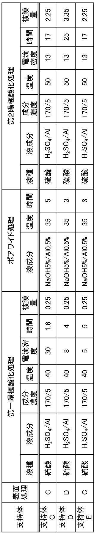
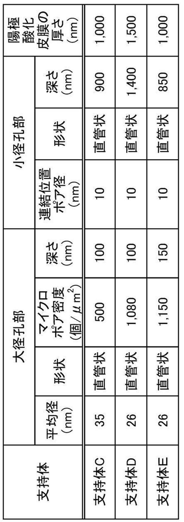
<下塗り層A~Cの形成方法>
表4に記載の支持体上に、表4に記載の下記組成の下塗り層塗布液A~Cのいずれかを乾燥塗布量が20mg/m2になるよう塗布して100℃のオーブンで30秒間乾燥し、下塗り層を形成した。
表4に記載の支持体上に、表4に記載の下記組成の下塗り層塗布液A~Cのいずれかを乾燥塗布量が20mg/m2になるよう塗布して100℃のオーブンで30秒間乾燥し、下塗り層を形成した。
-下塗り層塗布液Aの組成-
・ポリマー(U-1)〔下記構造〕:0.18部
・ヒドロキシエチルイミノ二酢酸:0.10部
・水:61.4部
・ポリマー(U-1)〔下記構造〕:0.18部
・ヒドロキシエチルイミノ二酢酸:0.10部
・水:61.4部
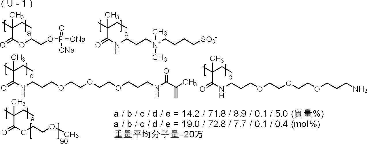
-下塗り層塗布液Bの組成-
・ポリマー(U-1):0.14部
・グルコン酸ナトリウム:0.07部
・界面活性剤(エマレックス710、日本エマルジョン(株)製):0.0016部
・防腐剤(バイオホープL、ケイ・アイ化成(株)製):0.0015部
・水:3.29部
・ポリマー(U-1):0.14部
・グルコン酸ナトリウム:0.07部
・界面活性剤(エマレックス710、日本エマルジョン(株)製):0.0016部
・防腐剤(バイオホープL、ケイ・アイ化成(株)製):0.0015部
・水:3.29部
-下塗り層塗布液Cの組成-
・ポリマー(U-1):0.14部
・キレスト400:0.035部
・キレスト3EAF:0.035部
・界面活性剤(エマレックス710、日本エマルジョン(株)製):0.0016部
・防腐剤(バイオホープL、ケイ・アイ化成(株)製):0.0015部
・水:3.29部
・ポリマー(U-1):0.14部
・キレスト400:0.035部
・キレスト3EAF:0.035部
・界面活性剤(エマレックス710、日本エマルジョン(株)製):0.0016部
・防腐剤(バイオホープL、ケイ・アイ化成(株)製):0.0015部
・水:3.29部
-ポリマー(U-1)の合成-
<<モノマーM-1の精製>>
ライトエステル P-1M(2-メタクリロイルオキシエチルアシッドホスフェート、共栄社化学(株)製)420部、ジエチレングリコールジブチルエーテル1,050部及び蒸留水1,050部を分液ロートに加え、激しく撹拌した後静置した。上層を廃棄した後、ジエチレングリコールジブチルエーテル1,050部を加え、激しく撹拌した後静置した。上層を廃棄してモノマーM-1の水溶液(固形分換算10.5質量%)を1,300部得た。
<<モノマーM-1の精製>>
ライトエステル P-1M(2-メタクリロイルオキシエチルアシッドホスフェート、共栄社化学(株)製)420部、ジエチレングリコールジブチルエーテル1,050部及び蒸留水1,050部を分液ロートに加え、激しく撹拌した後静置した。上層を廃棄した後、ジエチレングリコールジブチルエーテル1,050部を加え、激しく撹拌した後静置した。上層を廃棄してモノマーM-1の水溶液(固形分換算10.5質量%)を1,300部得た。
<<ポリマー(U-1)の合成>>
三口フラスコに、蒸留水を53.73部、以下に示すモノマーM-2を3.66部加え、窒素雰囲気下で55℃に昇温した。次に、以下に示す滴下液1を2時間掛けて滴下し、30分撹拌した後、VA-046B(富士フイルム和光純薬(株)製)0.386部を加え、80℃に昇温し、1.5時間撹拌した。反応液を室温(25℃)に戻した後、30質量%水酸化ナトリウム水溶液を加え、pHを8.0に調整したのち、4-ヒドロキシ-2,2,6,6-テトラメチルピペリジン-1-オキシル(4-OH-TEMPO)を0.005部加えた。以上の操作により、ポリマー(U-1)の水溶液を180部得た。ゲル浸透クロマトグラフィー(GPC)法によるポリエチレングリコール換算値とした重量平均分子量(Mw)は20万であった。
三口フラスコに、蒸留水を53.73部、以下に示すモノマーM-2を3.66部加え、窒素雰囲気下で55℃に昇温した。次に、以下に示す滴下液1を2時間掛けて滴下し、30分撹拌した後、VA-046B(富士フイルム和光純薬(株)製)0.386部を加え、80℃に昇温し、1.5時間撹拌した。反応液を室温(25℃)に戻した後、30質量%水酸化ナトリウム水溶液を加え、pHを8.0に調整したのち、4-ヒドロキシ-2,2,6,6-テトラメチルピペリジン-1-オキシル(4-OH-TEMPO)を0.005部加えた。以上の操作により、ポリマー(U-1)の水溶液を180部得た。ゲル浸透クロマトグラフィー(GPC)法によるポリエチレングリコール換算値とした重量平均分子量(Mw)は20万であった。

<<滴下液1の組成>>
・上記モノマーM-1水溶液:87.59部
・上記モノマーM-2:14.63部
・VA-046B(2,2’-アゾビス[2-(2-イミダゾリン-2-イル)プロパン]ジスルフェートジハイドレート、富士フイルム和光純薬(株)製):0.386部
・蒸留水:20.95部
・上記モノマーM-1水溶液:87.59部
・上記モノマーM-2:14.63部
・VA-046B(2,2’-アゾビス[2-(2-イミダゾリン-2-イル)プロパン]ジスルフェートジハイドレート、富士フイルム和光純薬(株)製):0.386部
・蒸留水:20.95部
<画像記録層の形成>
表4~表6に記載の組成の画像記録層塗布液(ただし、上記画像記録層塗布液は、表4~表6に記載の各成分を含み、かつ1-メトキシ-2-プロパノール(MFG):メチルエチルケトン(MEK):メタノール=4:4:1(質量比)の混合溶媒で固形分が6質量%になるように調製した。)を支持体又は下塗り層上にバー塗布し、120℃で40秒間オーブン乾燥して、乾燥塗布量1.0g/m2の画像記録層を形成した。
画像記録層に使用した各成分を以下に示す。
表4~表6に記載の組成の画像記録層塗布液(ただし、上記画像記録層塗布液は、表4~表6に記載の各成分を含み、かつ1-メトキシ-2-プロパノール(MFG):メチルエチルケトン(MEK):メタノール=4:4:1(質量比)の混合溶媒で固形分が6質量%になるように調製した。)を支持体又は下塗り層上にバー塗布し、120℃で40秒間オーブン乾燥して、乾燥塗布量1.0g/m2の画像記録層を形成した。
画像記録層に使用した各成分を以下に示す。
〔赤外線吸収剤〕
IR-1~IR-10:下記構造の化合物
IR-1~IR-10:下記構造の化合物


なお、Buはn-ブチル基を表し、Phはフェニル基を表し、TsO-はトシレートアニオンを表す。
〔電子受容型重合開始剤〕
Int-1~Int-7:下記構造の化合物、なお、TsO-は、トシレートアニオンを表し、Phはフェニル基を表す。
Int-1~Int-7:下記構造の化合物、なお、TsO-は、トシレートアニオンを表し、Phはフェニル基を表す。

〔電子供与型重合開始剤〕
B-1~B-4:下記構造の化合物
B-1~B-4:下記構造の化合物
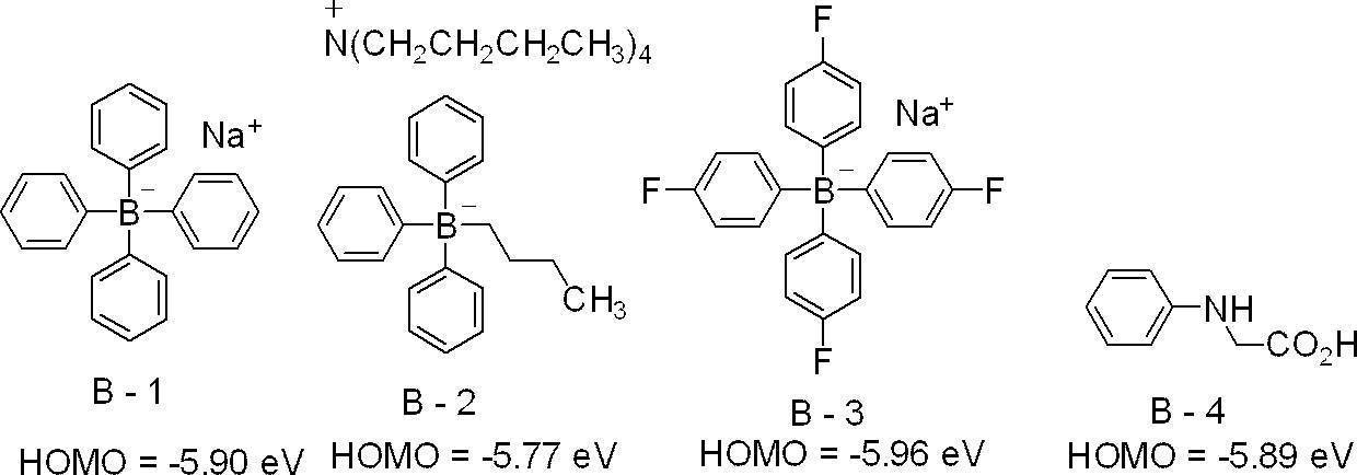
〔重合性化合物〕
M-1:下記化合物
M-2:下記化合物
M-3:ジペンタエリスリトールペンタアクリレート、サートマー社製SR-399
M-4:ウレタンアクリレート、新中村化学工業(株)製U-15HA
M-5:下記合成方法により合成したモノマー
M-1:下記化合物
M-2:下記化合物
M-3:ジペンタエリスリトールペンタアクリレート、サートマー社製SR-399
M-4:ウレタンアクリレート、新中村化学工業(株)製U-15HA
M-5:下記合成方法により合成したモノマー

<M-5の合成>
タケネートD-160N(ポリイソシアネート トリメチロールプロパンアダクト体、三井化学株式会社製、4.7部)、アロニックスM-403(東亞合成(株)製、タケネートD-160NのNCO価とアロニックスM-403の水酸基価が1:1となる量)、t-ブチルベンゾキノン(0.02部)、及びメチルエチルケトン(11.5部)の混合溶液を65℃に加熱した。反応溶液に、ネオスタンU-600(ビスマス系重縮合触媒、日東化成(株)製、0.11部)を加え、65℃で4時間加熱した。反応溶液を室温(25℃)まで冷却し、メチルエチルケトンを加えることで、固形分が50質量%のウレタンアクリレート溶液を合成した。リサイクル型GPC(機器:LC908-C60、カラム:JAIGEL-1H-40及び2H-40(日本分析工業(株)製))を用いて、テトラヒドロフラン(THF)の溶離液にて、ウレタンアクリレート(M-5)溶液の分子量分画を実施した。重量平均分子量は20,000であった。
タケネートD-160N(ポリイソシアネート トリメチロールプロパンアダクト体、三井化学株式会社製、4.7部)、アロニックスM-403(東亞合成(株)製、タケネートD-160NのNCO価とアロニックスM-403の水酸基価が1:1となる量)、t-ブチルベンゾキノン(0.02部)、及びメチルエチルケトン(11.5部)の混合溶液を65℃に加熱した。反応溶液に、ネオスタンU-600(ビスマス系重縮合触媒、日東化成(株)製、0.11部)を加え、65℃で4時間加熱した。反応溶液を室温(25℃)まで冷却し、メチルエチルケトンを加えることで、固形分が50質量%のウレタンアクリレート溶液を合成した。リサイクル型GPC(機器:LC908-C60、カラム:JAIGEL-1H-40及び2H-40(日本分析工業(株)製))を用いて、テトラヒドロフラン(THF)の溶離液にて、ウレタンアクリレート(M-5)溶液の分子量分画を実施した。重量平均分子量は20,000であった。
〔バインダーポリマー〕
P-1:ポリビニルアセタール、積水化学工業(株)製エスレックBX-5Z
P-2:ポリビニルアセタール、積水化学工業(株)製エスレックBL10
P-3:下記合成方法により合成された樹脂
P-1:ポリビニルアセタール、積水化学工業(株)製エスレックBX-5Z
P-2:ポリビニルアセタール、積水化学工業(株)製エスレックBL10
P-3:下記合成方法により合成された樹脂
<バインダーポリマーP-3の合成>
三口フラスコに、1-メトキシ-2-プロパノール:78.0部を秤取り、窒素気流下、70℃に加熱した。この反応容器に、ブレンマーPME-100(メトキシジエチレングリコールモノメタクリレート、日油(株)製):52.1部、メチルメタクリレート:21.8部、メタクリル酸:14.2部、ヘキサキス(3-メルカプトプロピオン酸)ジペンタエリスリトール:2.15部、V-601(2,2’-アゾビス(イソ酪酸)ジメチル、富士フイルム和光純薬(株)製):0.38部、1-メトキシ-2-プロパノール:54部からなる混合溶液を2時間30分かけて滴下した。滴下終了後、80℃に昇温し、更に2時間反応を続けた。V-601:0.04部、1-メトキシ-2-プロパノール:4部からなる混合溶液を加え、90℃に昇温して2.5時間反応を続けた。反応終了後、室温まで反応液を冷却した。
上記の反応溶液に1-メトキシ-2-プロパノール:137.2部、4-ヒドロキシテトラメチルピペリジン-N-オキシド:0.24部、グリシジルメタクリレート:26.0部、テトラエチルアンモニウムブロミド:3.0部を加えてよく撹拌した後、90℃にて加熱した。
18時間後、室温(25℃)まで反応溶液を冷却した後、1-メトキシ-2-プロパノール:99.4部を加えて希釈した。
こうして得られたバインダーポリマーP-3は、固形分濃度:23質量%、GPCで測定したポリスチレン換算重量平均分子量は3.5万であった。

〔酸発色剤〕
S-1~S-4:下記化合物
S-1~S-4:下記化合物

〔親水性化合物〕
T-1:トリス(2-ヒドロキシエチル)イソシアヌレート
T-2:下記構造の化合物
T-3:ヒドロキシプロピルセルロース、Klucel M、Hercules社製
T-1:トリス(2-ヒドロキシエチル)イソシアヌレート
T-2:下記構造の化合物
T-3:ヒドロキシプロピルセルロース、Klucel M、Hercules社製

〔界面活性剤〕
界面活性剤:アニオン性界面活性剤、ラピゾールA-80、日油(株)製
界面活性剤:アニオン性界面活性剤、ラピゾールA-80、日油(株)製
〔ポリマー粒子〕
<ポリマー粒子R-1の調製>
・ミクロゲル(ポリマー粒子R-1):2.640部
・蒸留水:2.425部
上記ミクロゲルの調製法を以下に示す。
<ポリマー粒子R-1の調製>
・ミクロゲル(ポリマー粒子R-1):2.640部
・蒸留水:2.425部
上記ミクロゲルの調製法を以下に示す。
-多価イソシアネート化合物の調製-
イソホロンジイソシアネート17.78部(80モル当量)と下記多価フェノール化合物(1)7.35部(20モル当量)との酢酸エチル(25.31部)懸濁溶液に、ビスマストリス(2-エチルヘキサノエート)(ネオスタン U-600、日東化成(株)製)0.043部を加えて撹拌した。発熱が収まった時点で反応温度を50℃に設定し、3時間撹拌して多価イソシアネート化合物(1)の酢酸エチル溶液(50質量%)を得た。
イソホロンジイソシアネート17.78部(80モル当量)と下記多価フェノール化合物(1)7.35部(20モル当量)との酢酸エチル(25.31部)懸濁溶液に、ビスマストリス(2-エチルヘキサノエート)(ネオスタン U-600、日東化成(株)製)0.043部を加えて撹拌した。発熱が収まった時点で反応温度を50℃に設定し、3時間撹拌して多価イソシアネート化合物(1)の酢酸エチル溶液(50質量%)を得た。

-ミクロゲルの調製-
下記油相成分及び水相成分を混合し、ホモジナイザーを用いて12,000rpmで10分間乳化した。得られた乳化物を45℃で4時間撹拌後、1,8-ジアザビシクロ[5.4.0]ウンデカ-7-エン-オクチル酸塩(U-CAT SA102、サンアプロ(株)製)の10質量%水溶液5.20gを加え、室温で30分撹拌し、45℃で24時間静置した。蒸留水で、固形分濃度を20質量%になるように調整し、ミクロゲルの水分散液が得られた。光散乱法により平均粒径を測定したところ、0.20μmであった。
下記油相成分及び水相成分を混合し、ホモジナイザーを用いて12,000rpmで10分間乳化した。得られた乳化物を45℃で4時間撹拌後、1,8-ジアザビシクロ[5.4.0]ウンデカ-7-エン-オクチル酸塩(U-CAT SA102、サンアプロ(株)製)の10質量%水溶液5.20gを加え、室温で30分撹拌し、45℃で24時間静置した。蒸留水で、固形分濃度を20質量%になるように調整し、ミクロゲルの水分散液が得られた。光散乱法により平均粒径を測定したところ、0.20μmであった。
~油相成分~
(成分1)酢酸エチル:12.0部
(成分2)トリメチロールプロパン(6モル当量)とキシレンジイソシアネート(18モル当量)を付加させ、これに片末端メチル化ポリオキシエチレン(1モル当量、オキシエチレン単位の繰返し数:90)を付加させた付加体(50質量%酢酸エチル溶液、三井化学(株)製):3.76部
(成分3)多価イソシアネート化合物(1)(50質量%酢酸エチル溶液として):15.0部
(成分4)ジペンタエリスリトールペンタアクリレート(SR-399、サートマー社製)の65質量%酢酸エチル溶液:11.54部
(成分5)スルホン酸塩型界面活性剤(パイオニンA-41-C、竹本油脂(株)製)の10%酢酸エチル溶液:4.42部
~水相成分~
蒸留水:46.87部
蒸留水:46.87部
<ポリマー粒子R-2の作製>
-油相成分の調製-
多官能イソシアネート化合物(PM-200:万華化学社製):6.66gと、三井化学(株)製の「タケネート(登録商標)D-116N(トリメチロールプロパン(TMP)とm-キシリレンジイソシアネート(XDI)とポリエチレングリコールモノメチルエーテル(EO90)との付加物(下記構造)」の50質量%酢酸エチル溶液:5.46gと、ジペンタエリスリトールペンタアクリレート(SR-399、サートマー社製)の65質量%酢酸エチル溶液:11.24gと、酢酸エチル:14.47gと、竹本油脂(株)製のパイオニン(登録商標)A-41-C:0.45gを混合し、室温(25℃)で15分攪拌して油相成分を得た。
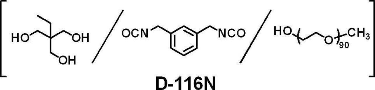
-水相成分の準備-
水相成分として、蒸留水47.2gを準備した。
水相成分として、蒸留水47.2gを準備した。
-マイクロカプセル形成工程-
油相成分に水相成分を添加して混合し、得られた混合物を、ホモジナイザーを用いて12,000rpmで16分間乳化させて乳化物を得た。
得られた乳化物に蒸留水16.8gを添加し、得られた液体を室温で10分撹拌した。
次いで、撹拌後の液体を45℃に加熱し、液温を45℃に保持した状態で4時間撹拌することにより、上記液体から酢酸エチルを留去した。次いで、1,8-ジアザビシクロ[5.4.0]ウンデカ-7-エン-オクチル酸塩(U-CAT SA102、サンアプロ(株)製)の10質量%水溶液5.12gを加え、室温で30分撹拌し、45℃で24時間静置した。蒸留水で、固形分濃度を20質量%になるように調整し、ポリマー粒子R-2の水分散液が得られた。R-2の体積平均粒径はレーザー回折/散乱式粒子径分布測定装置LA-920((株)堀場製作所製)により測定したところ、165nmであった。
<ポリマー粒子R-3の調製>
4つ口フラスコに、分散ユニット:下記化合物B-1(n=45):10.0部、蒸留水85.0部、及びn-プロパノール240.0部を加えて、窒素雰囲気下70℃で加熱撹拌した。
次に、4つ口フラスコに、予め混合された下記化合物A-1:20.0部、下記化合物A-2:70.0部及び2,2’-アゾビスイソブチロニトリル0.7部の混合物を2時間かけて滴下した。
滴下終了後5時間そのまま反応を続けた後、2,2’-アゾビスイソブチロニトリル0.5部を添加し、80℃に昇温した。6時間おきに2,2’-アゾビスイソブチロニトリルを0.4部ずつ添加し、計19時間反応させた。
反応液を室温(25℃)に放冷し、ポリマー粒子R-3の分散液(固形分23%)を得た。

ポリマー粒子R-3のメジアン径は150nmであって、変動係数は23%であった。
また、ポリマー粒子R-3の分散性について、既述の方法で確認したところ、樹脂粒子R-3は、水分散性を有する粒子であって、有機溶媒分散性を有する粒子であった。
また、ポリマー粒子R-3の分散性について、既述の方法で確認したところ、樹脂粒子R-3は、水分散性を有する粒子であって、有機溶媒分散性を有する粒子であった。
<ポリマー粒子R-4の調製>
3つ口フラスコに蒸留水350部、化合物A-1 50部、化合物A-2 20部、化合物A-3 20部、化合物B-1(n=45) 10部を加え、窒素雰囲気下で70℃に昇温した。次に過硫酸カリウム(KPS)を1.0部添加し3時間加熱撹拌した後に、95℃に昇温し4時間反応させた。反応液を室温(25℃)に放冷し、ポリマー粒子R-4の水分散液(固形分22%)を得た。ポリマー粒子R-4の平均粒径は142nmであった。
3つ口フラスコに蒸留水350部、化合物A-1 50部、化合物A-2 20部、化合物A-3 20部、化合物B-1(n=45) 10部を加え、窒素雰囲気下で70℃に昇温した。次に過硫酸カリウム(KPS)を1.0部添加し3時間加熱撹拌した後に、95℃に昇温し4時間反応させた。反応液を室温(25℃)に放冷し、ポリマー粒子R-4の水分散液(固形分22%)を得た。ポリマー粒子R-4の平均粒径は142nmであった。

<ポリマー粒子R-5の調製>
3つ口フラスコにイオン交換水288部、ドデシルベンゼンスルホン酸ナトリウム1.6部、A-1 0.5部、及び、A-2 0.2部添加し、窒素雰囲気下、75℃、200rpmで15分間撹拌及び乳化した。
過硫酸カリウム(KPS)0.15部、イオン交換水7部を添加し80℃で30分加熱撹拌した。
A-1 24.7部、A-2 12.8部、及び、A-4 6.7部を3時間かけて滴下した後、1時間加熱撹拌を継続した。反応液を室温(25℃)に放冷し、ポリマー粒子R-5の水分散液(固形分13%)を得た。ポリマー粒子R-5の平均粒径は40nmであった。
3つ口フラスコにイオン交換水288部、ドデシルベンゼンスルホン酸ナトリウム1.6部、A-1 0.5部、及び、A-2 0.2部添加し、窒素雰囲気下、75℃、200rpmで15分間撹拌及び乳化した。
過硫酸カリウム(KPS)0.15部、イオン交換水7部を添加し80℃で30分加熱撹拌した。
A-1 24.7部、A-2 12.8部、及び、A-4 6.7部を3時間かけて滴下した後、1時間加熱撹拌を継続した。反応液を室温(25℃)に放冷し、ポリマー粒子R-5の水分散液(固形分13%)を得た。ポリマー粒子R-5の平均粒径は40nmであった。


<最外層の形成>
表4に記載の組成の最外層塗布液(ただし、上記最外層塗布液は、表4に記載の各成分を含み、かつイオン交換水で固形分が6質量%になるように調製した。)を画像記録層上にバー塗布し、120℃で60秒間オーブン乾燥して、乾燥塗布量0.15g/m2の最外層を形成した。
表4に記載の組成の最外層塗布液(ただし、上記最外層塗布液は、表4に記載の各成分を含み、かつイオン交換水で固形分が6質量%になるように調製した。)を画像記録層上にバー塗布し、120℃で60秒間オーブン乾燥して、乾燥塗布量0.15g/m2の最外層を形成した。
なお、最外層塗布液に使用した無機層状化合物分散液(1)の調製法を以下に記載する。
<<無機層状化合物分散液(1)の調製>>
イオン交換水193.6部に合成雲母(ソマシフME-100、コープケミカル(株)製)6.4部を添加し、ホモジナイザーを用いて平均粒径(レーザー散乱法)が3μmになるまで分散した。得られた分散粒子のアスペクト比は100以上であった。
<<無機層状化合物分散液(1)の調製>>
イオン交換水193.6部に合成雲母(ソマシフME-100、コープケミカル(株)製)6.4部を添加し、ホモジナイザーを用いて平均粒径(レーザー散乱法)が3μmになるまで分散した。得られた分散粒子のアスペクト比は100以上であった。
〔変色性化合物〕
wIR-1~wIR-6:下記化合物
wIR-1~wIR-6:下記化合物
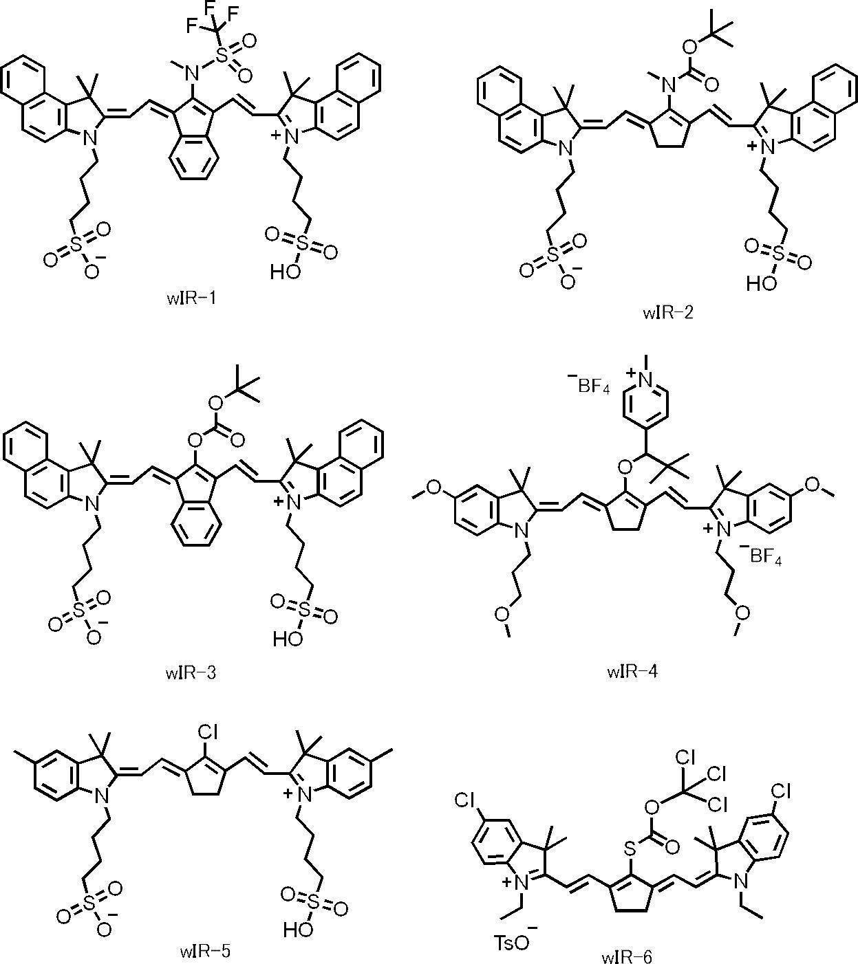
〔親水性ポリマー〕
WP-1:ポリビニルアルコール、シグマアルドリッチ社製Mowiol 4-88
WP-2:ポリビニルアルコール、シグマアルドリッチ社製Mowiol 8-88
WP-3:下記樹脂(Mw52,000)
WP-4:セルロース、信越化学工業(株)製メトローズ60SH-15
WP-5:ポリビニルアルコール、三菱ケミカル(株)製ゴーセノールL-3266、けん化度86~89%以上
WP-6:セルロース、信越化学工業(株)製メトローズSM04
WP-1:ポリビニルアルコール、シグマアルドリッチ社製Mowiol 4-88
WP-2:ポリビニルアルコール、シグマアルドリッチ社製Mowiol 8-88
WP-3:下記樹脂(Mw52,000)
WP-4:セルロース、信越化学工業(株)製メトローズ60SH-15
WP-5:ポリビニルアルコール、三菱ケミカル(株)製ゴーセノールL-3266、けん化度86~89%以上
WP-6:セルロース、信越化学工業(株)製メトローズSM04

〔疎水性ポリマー〕
L-1:ポリ塩化ビニリデン水性ディスパージョン、Solvin社製Diofan(登録商標) A50
L-2:スチレン-アクリル樹脂、日本ペイント・インダストリアルコーティングス(株)製FS-201
L-3:スチレン-アクリル樹脂、日本ペイント・インダストリアルコーティングス(株)製FS-102
L-1:ポリ塩化ビニリデン水性ディスパージョン、Solvin社製Diofan(登録商標) A50
L-2:スチレン-アクリル樹脂、日本ペイント・インダストリアルコーティングス(株)製FS-201
L-3:スチレン-アクリル樹脂、日本ペイント・インダストリアルコーティングス(株)製FS-102
<平版印刷版原版の作製>
表4~表6に記載の通り、それぞれ支持体及び上記各層の形成方法に従って、実施例1~18、並びに、比較例1及び2の平版印刷版原版をそれぞれ作製した。
表4~表6に記載の通り、それぞれ支持体及び上記各層の形成方法に従って、実施例1~18、並びに、比較例1及び2の平版印刷版原版をそれぞれ作製した。
<平版印刷版原版の評価>
〔UV耐刷性〕
上記のようにして作製した平版印刷版原版を、赤外線半導体レーザー搭載のKodak社製Magnus800 Quantumにて、出力27W、外面ドラム回転数450rpm、解像度2,400dpi(dots per inch、1inchは2.54cm)の条件で露光(照射エネルギー110mJ/cm2相当)した。露光画像にはベタ画像、及び、AMスクリーン(Amplitude Modulation Screen)3%網点のチャートを含むようにした。
得られた露光済み原版を現像処理することなく、菊判サイズのハイデルベルグ社製印刷機SX-74のシリンダーに取り付けた。本印刷機には、不織布フィルターと温度制御装置を内蔵する容量100Lの湿し水循環タンクを接続した。湿し水S-Z1(富士フイルム(株)製)2.0%の湿し水80Lを循環装置内に仕込み、印刷インクとしてT&K UV OFS K-HS墨GE-M((株)T&K TOKA製)を用い、標準の自動印刷スタート方法で湿し水とインクを供給した後、毎時10,000枚の印刷速度で特菱アート(三菱製紙(株)製、連量76.5kg)紙に印刷を行った。
印刷枚数を増やしていくと徐々に画像部が磨耗するため印刷物上のインク濃度が低下した。印刷物におけるAMスクリーン3%網点の網点面積率をグレタグ濃度計(GretagMacbeth社製)で計測した値が、印刷500枚目の計測値よりも1%低下したときの印刷部数を刷了枚数として耐刷性を評価した。印刷枚数が5万枚の場合を100とする相対耐刷性により評価した。数値が大きいほど、耐刷性が良好である。
相対耐刷性=(対象平版印刷版原版の印刷枚数)/50,000×100
〔UV版飛び抑制性〕
上記のようにして作製した平版印刷版原版を、赤外線半導体レーザー搭載のKodak社製Magnus800 Quantumにて、出力27W、外面ドラム回転数450rpm、解像度2,400dpi(dot per inch、1inchは2.54cm)の条件で露光(照射エネルギー110mJ/cm2相当)した。露光画像にはベタ画像、及び、AMスクリーン(Amplitude Modulated Screening)3%網点のチャートを含むようにした。
得られた露光済み原版の網点部に、直径0.4mmのピアノ線((株)エスコ)を版胴の回転方向に対して垂直方向に貼り付け、現像処理することなく、菊判サイズのハイデルベルグ社製印刷機SX-74のシリンダーに取り付けた。本印刷機には、不織布フィルターと温度制御装置を内蔵する容量100Lの湿し水循環タンクを接続した。湿し水S-Z1(富士フイルム(株)製)2.0%の湿し水80Lを循環装置内に仕込み、印刷インクとしてT&K UV OFS K-HS墨GE-M((株)T&K TOKA製)を用い、標準の自動印刷スタート方法で湿し水とインクを供給した後、毎時10,000枚の印刷速度で特菱アート(三菱製紙(株)製、連量:76.5kg)紙に印刷を行った。
印刷枚数が2,000枚に達したところで、版からピアノ線を取り外し、再度印刷機にセットし、印刷を開始した。再開後100枚目の印刷物を確認し、ピアノ線の位置に対応する画像部を確認し、着肉不良が生じているか50倍拡大鏡を用いて目視で確認した。同様に2,000枚ごとに確認を行い、着肉不良が生じた段階で評価を終了した。
なお、着肉不良が生じるまでの印刷枚数が多いほど、「UV版飛び抑制性」に優れるといえる。
-評価基準-
A:着肉不良が生じるまでの印刷枚数が20,000枚以上である。
B:着肉不良が生じるまでの印刷枚数が4,000枚以上20,000枚未満である。
C:着肉不良が生じるまでの印刷枚数が4,000枚未満である。
〔筋ムラ適性(GLV適性)評価〕
上記のようにして作製した平版印刷版原版を、GLV(Grating Light Value)技術を採用した露光ヘッドを搭載した露光機(PlateRite HD 8900Nシリーズ、(株)SCREENグラフィックソリューション製)を用いて、露光エネルギー110mJ/cm2で露光した。露光画像には、AMスクリーン200線及びFMスクリーン(Frequency Modulation Screen)20μmの平網のチャートを含むようにした。
得られた露光済み原版を現像処理することなく、SOR-M単色印刷機(ハイデルベルグ社製)に取り付け、インク:Fusion-G MK紅N(DIC(株)製)、湿し水:S-S2 2%希釈(富士フイルム(株)製)、ブランケット:DAYブランケットD 3000((株)T&K TOKA製)、紙:特菱アート127.9gsm(g/m2)(三菱製紙(株)製)を用いて、1,000枚印刷を行った。そして、1,000枚目の印刷紙面より、目視でスジ状のムラの発生度合いを官能評価した。スジ状のムラが見られないほど、GLV適性に優れるともいう。
-評価基準-
A:FMスクリーン及びAMスクリーンともに、スジ状のムラがみられない。
B:FMスクリーンのみ、スジ状のムラが僅かにみられる。
C:FMスクリーン及びAMスクリーンともに、スジ状のムラが僅かにみられる。
D:FMスクリーン及びAMスクリーンともに、スジ状のムラがみられる。
〔経時安定性評価〕
上記で作製された平版印刷版原版(調液及び塗布を2日間で実施し、版が出来てから室温で3日以内)の現像性の評価結果をD(Fr)枚、上記版を50℃70%RH湿度条件で3日間保管した版の現像性をD(Th)枚とした際、版の経時安定性ΔDは下記式で求められる。
ΔD=D(Th)/D(Fr)
ΔDの値が1に近いほど、経時安定性に優れる版である。
-評価基準-
A:1.0≦ΔD≦1.5
B:1.5≦ΔD≦2.0
C:2.0≦ΔD
上記で作製された平版印刷版原版(調液及び塗布を2日間で実施し、版が出来てから室温で3日以内)の現像性の評価結果をD(Fr)枚、上記版を50℃70%RH湿度条件で3日間保管した版の現像性をD(Th)枚とした際、版の経時安定性ΔDは下記式で求められる。
ΔD=D(Th)/D(Fr)
ΔDの値が1に近いほど、経時安定性に優れる版である。
-評価基準-
A:1.0≦ΔD≦1.5
B:1.5≦ΔD≦2.0
C:2.0≦ΔD


なお、ΔE1は、電子受容型重合開始剤のLUMO-赤外線吸収剤のLUMOの値を表す。
表4~表6に記載した結果から、実施例に係る平版印刷版原版は、比較例に係る平版印刷版原版と比べて、経時安定性に優れた平版印刷版原版が得られることがわかる。また、本開示に係る平版印刷版原版は、UV耐刷性、UV版飛び抑制性及び、視認性にも優れた平版印刷版が得られることがわかる。
表4~表6に記載した結果から、実施例に係る平版印刷版原版は、比較例に係る平版印刷版原版と比べて、経時安定性に優れた平版印刷版原版が得られることがわかる。また、本開示に係る平版印刷版原版は、UV耐刷性、UV版飛び抑制性及び、視認性にも優れた平版印刷版が得られることがわかる。
(実施例19~23)
<支持体Zの作製>
実施例19~23においては、以下の手順にて、支持体Zを作製した。
<支持体Zの作製>
実施例19~23においては、以下の手順にて、支持体Zを作製した。
-アルカリエッチング処理-
アルミニウム板に、カセイソーダ濃度26質量%及びアルミニウムイオン濃度6.5質量%のカセイソーダ水溶液を、温度55℃でスプレーにより吹き付けてエッチング処理を行った。その後、スプレーによる水洗を行った。後に電気化学的粗面化処理を施す面のアルミニウム溶解量は、3g/m2であった。
アルミニウム板に、カセイソーダ濃度26質量%及びアルミニウムイオン濃度6.5質量%のカセイソーダ水溶液を、温度55℃でスプレーにより吹き付けてエッチング処理を行った。その後、スプレーによる水洗を行った。後に電気化学的粗面化処理を施す面のアルミニウム溶解量は、3g/m2であった。
-酸性水溶液を用いたデスマット処理(第1デスマット処理)-
次に、酸性水溶液を用いてデスマット処理を行った。デスマット処理に用いる酸性水溶液は、硫酸170g/Lの水溶液を用いた。その液温は30℃であった。酸性水溶液をアルミニウム板にスプレーにて吹き付けて、3秒間デスマット処理を行った。その後、水洗処理を行った。
次に、酸性水溶液を用いてデスマット処理を行った。デスマット処理に用いる酸性水溶液は、硫酸170g/Lの水溶液を用いた。その液温は30℃であった。酸性水溶液をアルミニウム板にスプレーにて吹き付けて、3秒間デスマット処理を行った。その後、水洗処理を行った。
-電気化学的粗面化処理-
次に、塩酸濃度電解液を用い、交流電流を用いて電気化学的粗面化処理を行った。電解液の液温は40℃であった。交流電流の波形は正と負の波形が対称な正弦波であり、周波数は50Hzで行った。また、電気量はアルミニウム板がアノード反応に預かる電気量の総和で300C/dm2で行った。アルミニウム板の対極にはカーボン電極を用いた。その後、水洗処理を行った。
次に、塩酸濃度電解液を用い、交流電流を用いて電気化学的粗面化処理を行った。電解液の液温は40℃であった。交流電流の波形は正と負の波形が対称な正弦波であり、周波数は50Hzで行った。また、電気量はアルミニウム板がアノード反応に預かる電気量の総和で300C/dm2で行った。アルミニウム板の対極にはカーボン電極を用いた。その後、水洗処理を行った。
-アルカリエッチング処理-
電気化学的粗面化処理後のアルミニウム板に、カセイソーダ濃度5質量%及びアルミニウムイオン濃度0.5質量%のカセイソーダ水溶液を、温度35℃でスプレーにより吹き付けてエッチング量が0.1g/m2以下となるようエッチング処理を行った。その後、水洗処理を行った。
電気化学的粗面化処理後のアルミニウム板に、カセイソーダ濃度5質量%及びアルミニウムイオン濃度0.5質量%のカセイソーダ水溶液を、温度35℃でスプレーにより吹き付けてエッチング量が0.1g/m2以下となるようエッチング処理を行った。その後、水洗処理を行った。
-酸性水溶液を用いたデスマット処理-
次に、酸性水溶液を用いてデスマット処理を行った。デスマット処理に用いる酸性水溶液は、硫酸170g/Lの水溶液を用いた。その液温は30℃であった。酸性水溶液をアルミニウム板にスプレーにて吹き付けて、3秒間デスマット処理を行った。その後、水洗処理を行った。
次に、酸性水溶液を用いてデスマット処理を行った。デスマット処理に用いる酸性水溶液は、硫酸170g/Lの水溶液を用いた。その液温は30℃であった。酸性水溶液をアルミニウム板にスプレーにて吹き付けて、3秒間デスマット処理を行った。その後、水洗処理を行った。
-陽極酸化処理-
硫酸液170g/L、液温度40℃にて、直流電流を用いて、陽極酸化皮膜量が3g/m2となるよう陽極酸化処理を行った。
硫酸液170g/L、液温度40℃にて、直流電流を用いて、陽極酸化皮膜量が3g/m2となるよう陽極酸化処理を行った。
<下塗り層の形成方法>
表7に記載の支持体上に、表7に記載の下塗り層塗布液を乾燥塗布量が20mg/m2になるよう塗布して100℃のオーブンで30秒間乾燥し、下塗り層を形成した。
表7に記載の支持体上に、表7に記載の下塗り層塗布液を乾燥塗布量が20mg/m2になるよう塗布して100℃のオーブンで30秒間乾燥し、下塗り層を形成した。
<画像記録層の形成>
表7に記載の組成の画像記録層塗布液(ただし、上記画像記録層塗布液は、表7に記載の各成分を含み、かつ1-メトキシ-2-プロパノール(MFG):メチルエチルケトン(MEK):メタノール=4:4:1(質量比)の混合溶媒で固形分が6質量%になるように調製した。)を支持体又は下塗り層上にバー塗布し、120℃で40秒間オーブン乾燥して、乾燥塗布量1.0g/m2の画像記録層を形成した。
表7に記載の組成の画像記録層塗布液(ただし、上記画像記録層塗布液は、表7に記載の各成分を含み、かつ1-メトキシ-2-プロパノール(MFG):メチルエチルケトン(MEK):メタノール=4:4:1(質量比)の混合溶媒で固形分が6質量%になるように調製した。)を支持体又は下塗り層上にバー塗布し、120℃で40秒間オーブン乾燥して、乾燥塗布量1.0g/m2の画像記録層を形成した。
<最外層の形成>
表7に記載の組成の最外層塗布液(ただし、上記最外層塗布液は、表7に記載の各成分を含み、かつイオン交換水で固形分が6質量%になるように調製した。)を画像記録層上にバー塗布し、120℃で60秒間オーブン乾燥して、乾燥塗布量0.15g/m2の最外層を形成した。
表7に記載の組成の最外層塗布液(ただし、上記最外層塗布液は、表7に記載の各成分を含み、かつイオン交換水で固形分が6質量%になるように調製した。)を画像記録層上にバー塗布し、120℃で60秒間オーブン乾燥して、乾燥塗布量0.15g/m2の最外層を形成した。
<平版印刷版原版の作製>
表7に記載の通り、それぞれ支持体及び上記各層の形成方法に従って、実施例19~23の平版印刷版原版をそれぞれ作製した。
得られた平版印刷版原版を用い、実施例1と同様にして、各種評価を行った評価結果を表7に示す。
表7に記載の通り、それぞれ支持体及び上記各層の形成方法に従って、実施例19~23の平版印刷版原版をそれぞれ作製した。
得られた平版印刷版原版を用い、実施例1と同様にして、各種評価を行った評価結果を表7に示す。

上述した以外の表7に記載の略称の詳細を、以下に示す。
<赤外線吸収剤>
IR-11~IR-14:下記化合物
なお、TsO-はトシレートアニオンを表す。
<赤外線吸収剤>
IR-11~IR-14:下記化合物
なお、TsO-はトシレートアニオンを表す。

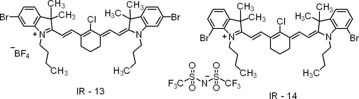
<界面活性剤>
U’-1及びU’-2:下記化合物
U’-3:アニオン界面活性剤、ラピゾールA-80、日油(株)製
U’-1及びU’-2:下記化合物
U’-3:アニオン界面活性剤、ラピゾールA-80、日油(株)製

表7に記載した結果から、実施例に係る平版印刷版原版は、比較例に係る平版印刷版原版と比べて、経時安定性に優れた平版印刷版原版が得られることがわかる。また、本開示に係る平版印刷版原版は、UV耐刷性、UV版飛び抑制性及び、視認性にも優れた平版印刷版が得られることがわかる。
18:アルミニウム板、ta:アノード反応時間、tc:カソード反応時間、tp:電流が0からピークに達するまでの時間、Ia:アノードサイクル側のピーク時の電流、Ic:カソードサイクル側のピーク時の電流、AA:アルミニウム板のアノード反応の電流、CA:アルミニウム板のカソード反応の電流、1:アルミニウム板、2及び4:ローラ状ブラシ、3:研磨スラリー液、5、6、7及び8:支持ローラ、10:平版印刷版原版、12a,12b:アルミニウム支持体、14:下塗り層、16:画像記録層、18:アルミニウム板、20a,20b:陽極酸化皮膜、22a,22b:マイクロポア、24:大径孔部、26:小径孔部、D:大径孔部の深さ、50:主電解槽、51:交流電源、52:ラジアルドラムローラ、53a,53b:主極、54:電解液供給口、55:電解液、56:補助陽極、60:補助陽極槽、W:アルミニウム板、S:給液方向、Ex:電解液排出方向、610:陽極酸化処理装置、612:給電槽、614:電解処理槽、616:アルミニウム板、618,26:電解液、620:給電電極、622,628:ローラ、624:ニップローラ、630:電解電極、632:槽壁、634:直流電源
2020年5月29日に出願された日本国特許出願第2020-095076号の開示及び2020年7月21日に出願された日本国特許出願第2020-124464号の開示は、その全体が参照により本明細書に取り込まれる。
本明細書に記載された全ての文献、特許出願、及び、技術規格は、個々の文献、特許出願、及び、技術規格が参照により取り込まれることが具体的かつ個々に記された場合と同程度に、本明細書中に参照により取り込まれる。
本明細書に記載された全ての文献、特許出願、及び、技術規格は、個々の文献、特許出願、及び、技術規格が参照により取り込まれることが具体的かつ個々に記された場合と同程度に、本明細書中に参照により取り込まれる。
Claims (31)
- 支持体と、画像記録層と、最外層とをこの順で有し、
前記画像記録層が、赤外線吸収剤、電子受容型重合開始剤、及び、重合性化合物を含み、
前記電子受容型重合開始剤のLUMO-前記赤外線吸収剤のLUMOの値が、0.45eV以上であり、
前記最外層が、変色性化合物を含む
機上現像型平版印刷版原版。 - 前記電子受容型重合開始剤のLUMO-前記赤外線吸収剤のLUMOの値が、0.62eV以上である請求項1に記載の機上現像型平版印刷版原版。
- 前記赤外線吸収剤のLUMOが、-3.80eVより小さい請求項1又は請求項2に記載の機上現像型平版印刷版原版。
- 前記赤外線吸収剤が、下記式1で表される化合物を含む請求項1~請求項3のいずれか1項に記載の機上現像型平版印刷版原版。
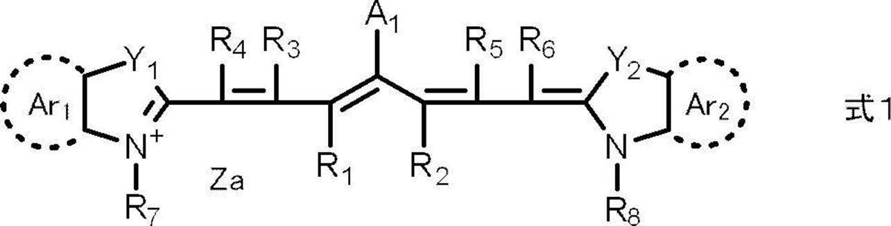
式1中、R1及びR2はそれぞれ独立に、水素原子又はアルキル基を表し、R1及びR2は互いに連結して環を形成してもよく、R3~R6はそれぞれ独立に、水素原子又はアルキル基を表し、R7及びR8はそれぞれ独立に、アルキル基又はアリール基を表し、Y1及びY2はそれぞれ独立に、酸素原子、硫黄原子、-NR0-又はジアルキルメチレン基を表し、R0は水素原子、アルキル基又はアリール基を表し、Ar1及びAr2はそれぞれ独立に、後述する式2で表される基を有していてもよいベンゼン環又はナフタレン環を形成する基を表し、A1は、-NR9R10、-X1-L1又は後述する式2で表される基を表し、R9及びR10はそれぞれ独立に、アルキル基、アリール基、アルコキシカルボニル基又はアリールスルホニル基を表し、X1は酸素原子又は硫黄原子を表し、L1は炭化水素基、ヘテロアリール基、又は、熱若しくは赤外線露光によりX1との結合が開裂する基を表し、Zaは電荷を中和する対イオンを表し、Ar1及びAr2の少なくとも一方に、下記式2で表される基を有する。
-X 式2
式2中、Xは、ハロゲン原子、-C(=O)-X2-R11、-C(=O)-NR12R13、-O-C(=O)-R14、-CN、-SO2NR15R16、又は、パーフルオロアルキル基を表し、X2は、単結合又は酸素原子を表し、R11及びR14はそれぞれ独立に、アルキル基又はアリール基を表し、R12、R13、R15及びR16はそれぞれ独立に、水素原子、アルキル基又はアリール基を表す。 - 式(1)におけるAr1及びAr2の少なくとも一方に、ハロゲン原子を有する請求項4に記載の機上現像型平版印刷版原版。
- 式(1)におけるAr1及びAr2の少なくとも一方に、臭素原子を有する請求項5に記載の機上現像型平版印刷版原版。
- 前記電子受容型重合開始剤のLUMOが、-3.2eVより大きい請求項1~請求項6のいずれか1項に記載の機上現像型平版印刷版原版。
- 前記電子受容型重合開始剤が、オニウム塩化合物である請求項1~請求項7のいずれか1項に記載の機上現像型平版印刷版原版。
- 前記電子受容型重合開始剤が、下記式(II)で表される化合物を含む請求項1~請求項8のいずれか1項に記載の機上現像型平版印刷版原版。

式(II)中、XAはハロゲン原子を表し、RAはアリール基を表す。 - 前記重合性化合物が、2官能以下の重合性化合物を含む請求項1~請求項9のいずれか1項に記載の機上現像型平版印刷版原版。
- 前記画像記録層が、ポリビニルアセタールを更に含む請求項1~請求項10のいずれか1項に記載の機上現像型平版印刷版原版。
- 前記最外層が、疎水性ポリマーを含む請求項1~請求項11のいずれか1項に記載の機上現像型平版印刷版原版。
- 前記疎水性ポリマーが、疎水性ポリマー粒子である請求項12に記載の機上現像型平版印刷版原版。
- エネルギー密度110mJ/cm2にて波長830nmの赤外線による露光を行った場合の、前記露光前後の明度変化ΔLが、2.0以上である請求項1~請求項13のいずれか1項に記載の機上現像型平版印刷版原版。
- 前記変色性化合物が、赤外線露光に起因して発色する化合物を含む請求項1~請求項14のいずれか1項に記載の機上現像型平版印刷版原版。
- 前記変色性化合物が、赤外線露光に起因して分解する分解性化合物を含む請求項1~請求項15のいずれか1項に記載の機上現像型平版印刷版原版。
- 前記変色性化合物が、シアニン色素である請求項1~請求項15のいずれか1項に記載の機上現像型平版印刷版原版。
- 前記変色性化合物が、下記式1-1で表される化合物である請求項1~請求項16のいずれか1項に記載の機上現像型平版印刷版原版。
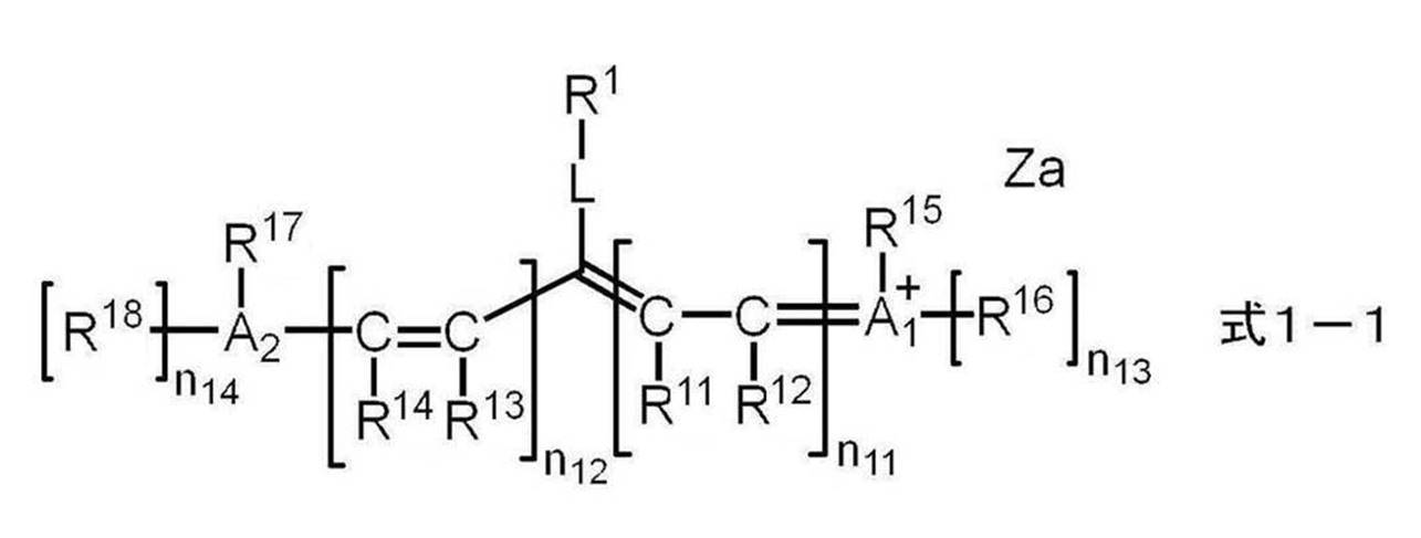
式1-1中、R1は下記式2-1~式4-1のいずれかで表される基を表し、R11~R18はそれぞれ独立に、水素原子、ハロゲン原子、-Ra、-ORb、-SRc、又は-NRdReを表し、Ra~Reはそれぞれ独立に、炭化水素基を表し、A1、A2及び複数のR11~R18が連結して単環又は多環を形成してもよく、A1及びA2はそれぞれ独立に、酸素原子、硫黄原子、又は、窒素原子を表し、n11及びn12はそれぞれ独立に、0~5の整数を表し、ただし、n11及びn12の合計は2以上であり、n13及びn14はそれぞれ独立に、0又は1を表し、Lは酸素原子、硫黄原子、又は、-N(R10)-を表し、R10は、水素原子、アルキル基又はアリール基を表し、Zaは電荷を中和する対イオンを表す。

式2-1~式4-1中、R20、R30、R41及びR42はそれぞれ独立に、アルキル基又はアリール基を表し、Zbは電荷を中和する対イオンを表し、波線は、前記式1-1中のLで表される基との結合部位を表す。 - 前記変色性化合物が、下記式1-2で表される化合物である請求項18に記載の機上現像型平版印刷版原版。

式1-2中、R1は前記式2-1~式4-1のいずれかで表される基を表し、R19~R22はそれぞれ独立に、水素原子、ハロゲン原子、-Ra、-ORb、-CN、-SRc、又は、-NRdReを表し、R23及びR24はそれぞれ独立に、-Raを表し、Ra~Reはそれぞれ独立に、炭化水素基を表し、R19とR20、R21とR22、又は、R23とR24は、連結して単環又は多環を形成してもよく、Lは、酸素原子、硫黄原子、又は、-N(R10)-を表し、R10は、水素原子、アルキル基、又は、アリール基を表し、Rd1~Rd4、W1及びW2は、それぞれ独立に、置換基を有してもよいアルキル基を表し、Zaは電荷を中和する対イオンを表す。 - 前記変色性化合物が、下記式1-3~式1-7のいずれかで表される化合物である請求項18又は請求項19に記載の機上現像型平版印刷版原版。

式1-3~式1-7中、R1は前記式2-1~式4-1のいずれかで表される基を表し、R19~R22はそれぞれ独立に、水素原子、ハロゲン原子、-Ra、-ORb、-CN、-SRc、又は、-NRdReを表し、R25及びR26はそれぞれ独立に、水素原子、ハロゲン原子、又は-Raを表し、Ra~Reはそれぞれ独立に、炭化水素基を表し、R19とR20、R21とR22、又は、R25とR26は、連結して単環又は多環を形成してもよく、Lは、酸素原子、硫黄原子、又は、-N(R10)-を表し、R10は、水素原子、アルキル基、又は、アリール基を表し、Rd1~Rd4、W1及びW2はそれぞれ独立に、置換基を有してもよいアルキル基を表し、Zaは電荷を中和する対イオンを表す。 - 前記式1-2~式1-7におけるW1及びW2はそれぞれ独立に、置換基を有するアルキル基であり、かつ、前記置換基として、-OCH2CH2-、スルホ基、スルホ基の塩、カルボキシ基、又は、カルボキシ基の塩を少なくとも有する基である請求項19又は請求項20に記載の機上現像型平版印刷版原版。
- 前記画像記録層が、電子供与型重合開始剤を更に含む、請求項1~請求項21のいずれか1項に記載の機上現像型平版印刷版原版。
- 前記電子供与型重合開始剤が、ボレート化合物である請求項22に記載の機上現像型平版印刷版原版。
- 前記電子受容型重合開始剤及び前記電子供与型重合開始剤として、前記電子受容性重合開始剤構造を有するカチオンと前記電子供与型重合開始剤構造を有するアニオンとが塩を形成してなる化合物を含む請求項22又は請求項23に記載の機上現像型平版印刷版原版。
- 前記赤外線吸収剤のHOMO-前記電子供与型重合開始剤のHOMOの値が、0.70eV以下である請求項22~請求項24のいずれか1項に記載の機上現像型平版印刷版原版。
- 前記重合性化合物が、7官能以上の重合性化合物を含む請求項1~請求項25のいずれか1項に記載の機上現像型平版印刷版原版。
- 前記重合性化合物が、10官能以上の重合性化合物を含む請求項1~請求項26のいずれか1項に記載の機上現像型平版印刷版原版。
- 前記支持体が、アルミニウム板と、前記アルミニウム板上に配置されたアルミニウムの陽極酸化皮膜とを有し、
前記陽極酸化皮膜が、前記アルミニウム板よりも前記画像記録層側に位置し、
前記陽極酸化皮膜が、前記画像記録層側の表面から深さ方向にのびるマイクロポアを有し、
前記マイクロポアの前記陽極酸化皮膜表面における平均径が、10nmを超え100nm以下である、請求項1~請求項27のいずれか1項に記載の機上現像型平版印刷版原版。 - 前記マイクロポアが、前記陽極酸化皮膜表面から深さ10nm~1,000nmの位置までのびる大径孔部と、前記大径孔部の底部と連通し、連通位置から深さ20nm~2,000nmの位置までのびる小径孔部とから構成され、
前記大径孔部の前記陽極酸化皮膜表面における平均径が、15nm~100nmであり、
前記小径孔部の前記連通位置における平均径が、13nm以下である、請求項28に記載の機上現像型平版印刷版原版。 - 請求項1~請求項29のいずれか1項に記載の機上現像型平版印刷版原版を、画像様に露光する工程と、
印刷機上で印刷インク及び湿し水よりなる群から選ばれた少なくとも一方を供給して非画像部の画像記録層を除去する工程と、を含む
平版印刷版の作製方法。 - 請求項1~請求項29のいずれか1項に記載の機上現像型平版印刷版原版を、画像様に露光する工程と、
印刷機上で印刷インク及び湿し水よりなる群から選ばれた少なくとも一方を供給して非画像部の画像記録層を除去し平版印刷版を作製する工程と、
得られた平版印刷版により印刷する工程と、を含む
平版印刷方法。
Priority Applications (4)
| Application Number | Priority Date | Filing Date | Title |
|---|---|---|---|
| EP21813150.6A EP4159458A4 (en) | 2020-05-29 | 2021-05-21 | LITHOGRAPHIC PRINTING PLATE PRECURSOR WITH DEVELOPMENT ON THE PRINTING PRESS, LITHOGRAPHIC PRINTING PLATE PRODUCTION PROCESS AND LITHOGRAPHIC PRINTING PROCESS |
| JP2022527002A JP7413526B2 (ja) | 2020-05-29 | 2021-05-21 | 機上現像型平版印刷版原版、平版印刷版の作製方法、及び、平版印刷方法 |
| CN202180039140.8A CN115697719A (zh) | 2020-05-29 | 2021-05-21 | 机上显影型平版印刷版原版、平版印刷版的制作方法及平版印刷方法 |
| US18/059,256 US20230127702A1 (en) | 2020-05-29 | 2022-11-28 | On-press development type lithographic printing plate precursor, method of preparing lithographic printing plate, and lithographic printing method |
Applications Claiming Priority (4)
| Application Number | Priority Date | Filing Date | Title |
|---|---|---|---|
| JP2020095076 | 2020-05-29 | ||
| JP2020-095076 | 2020-05-29 | ||
| JP2020-124464 | 2020-07-21 | ||
| JP2020124464 | 2020-07-21 |
Related Child Applications (1)
| Application Number | Title | Priority Date | Filing Date |
|---|---|---|---|
| US18/059,256 Continuation US20230127702A1 (en) | 2020-05-29 | 2022-11-28 | On-press development type lithographic printing plate precursor, method of preparing lithographic printing plate, and lithographic printing method |
Publications (1)
| Publication Number | Publication Date |
|---|---|
| WO2021241457A1 true WO2021241457A1 (ja) | 2021-12-02 |
Family
ID=78744695
Family Applications (1)
| Application Number | Title | Priority Date | Filing Date |
|---|---|---|---|
| PCT/JP2021/019462 WO2021241457A1 (ja) | 2020-05-29 | 2021-05-21 | 機上現像型平版印刷版原版、平版印刷版の作製方法、及び、平版印刷方法 |
Country Status (5)
| Country | Link |
|---|---|
| US (1) | US20230127702A1 (ja) |
| EP (1) | EP4159458A4 (ja) |
| JP (1) | JP7413526B2 (ja) |
| CN (1) | CN115697719A (ja) |
| WO (1) | WO2021241457A1 (ja) |
Cited By (4)
| Publication number | Priority date | Publication date | Assignee | Title |
|---|---|---|---|---|
| WO2022212032A1 (en) * | 2021-04-01 | 2022-10-06 | Eastman Kodak Company | Lithographic printing plate precursor and method of use |
| US20220324220A1 (en) * | 2021-04-01 | 2022-10-13 | Eastman Kodak Company | Lithographic printing plate precursor and method of use |
| WO2023167796A1 (en) * | 2022-03-03 | 2023-09-07 | Eastman Kodak Company | Lithographic printing plate precursor and method of use |
| WO2024035548A1 (en) * | 2022-08-12 | 2024-02-15 | Eastman Kodak Company | Lithographic printing plate precursor and method of use |
Citations (46)
| Publication number | Priority date | Publication date | Assignee | Title |
|---|---|---|---|---|
| JPH02304441A (ja) | 1989-05-18 | 1990-12-18 | Fuji Photo Film Co Ltd | 感光性平版印刷版 |
| JPH055005A (ja) | 1991-04-26 | 1993-01-14 | Kyowa Hakko Kogyo Co Ltd | 光重合開始剤およびこれを含有する光重合性組成物 |
| JPH0545885A (ja) | 1991-08-19 | 1993-02-26 | Fuji Photo Film Co Ltd | 感光性平版印刷版 |
| JPH0635174A (ja) | 1992-07-16 | 1994-02-10 | Fuji Photo Film Co Ltd | 感光性平版印刷版およびその処理方法 |
| JPH09123387A (ja) | 1995-10-24 | 1997-05-13 | Agfa Gevaert Nv | 印刷機上現像を含む平版印刷版の製造方法 |
| JPH09131850A (ja) | 1995-10-24 | 1997-05-20 | Agfa Gevaert Nv | 印刷機上現像を含む平版印刷版の製造方法 |
| JPH09171250A (ja) | 1995-11-09 | 1997-06-30 | Agfa Gevaert Nv | 感熱性像形成要素およびそれらを用いて印刷版を製造する方法 |
| JPH09171249A (ja) | 1995-11-09 | 1997-06-30 | Agfa Gevaert Nv | 感熱性像形成要素およびそれを用いて印刷版を製造する方法 |
| JPH10282679A (ja) | 1997-04-08 | 1998-10-23 | Fuji Photo Film Co Ltd | ネガ型感光性平版印刷版 |
| JP2001133969A (ja) | 1999-11-01 | 2001-05-18 | Fuji Photo Film Co Ltd | ネガ型平版印刷版原版 |
| JP2001222101A (ja) | 2000-02-09 | 2001-08-17 | Mitsubishi Paper Mills Ltd | 感光性組成物および感光性平版印刷版材料 |
| JP2001277740A (ja) | 2000-01-27 | 2001-10-10 | Fuji Photo Film Co Ltd | 平版印刷版用原版 |
| JP2001277742A (ja) | 2000-01-27 | 2001-10-10 | Fuji Photo Film Co Ltd | 平版印刷版用原版 |
| JP2002023360A (ja) | 2000-07-12 | 2002-01-23 | Fuji Photo Film Co Ltd | ネガ型画像記録材料 |
| JP2002040638A (ja) | 2000-07-25 | 2002-02-06 | Fuji Photo Film Co Ltd | ネガ型画像記録材料及び画像形成方法 |
| JP2002278057A (ja) | 2001-01-15 | 2002-09-27 | Fuji Photo Film Co Ltd | ネガ型画像記録材料及びシアニン色素 |
| EP0931647B1 (en) | 1998-01-23 | 2003-04-02 | Agfa-Gevaert | A heat sensitive element and a method for producing lithographic plates therewith |
| JP2005125749A (ja) | 2003-09-30 | 2005-05-19 | Fuji Photo Film Co Ltd | 平版印刷版原版および平版印刷方法 |
| JP2005238816A (ja) | 2003-07-22 | 2005-09-08 | Fuji Photo Film Co Ltd | 平版印刷版原版および平版印刷方法 |
| JP2005250216A (ja) | 2004-03-05 | 2005-09-15 | Fuji Photo Film Co Ltd | ネガ型平版印刷版原版およびこれを用いた平版印刷版の製版方法 |
| JP2006188038A (ja) | 2004-12-10 | 2006-07-20 | Fuji Photo Film Co Ltd | 平版印刷版原版および製版方法 |
| JP2006215263A (ja) | 2005-02-03 | 2006-08-17 | Fuji Photo Film Co Ltd | 平版印刷版原版 |
| JP2006239867A (ja) | 2005-02-28 | 2006-09-14 | Fuji Photo Film Co Ltd | 平版印刷版原版および平版印刷方法 |
| JP2006259137A (ja) | 2005-03-16 | 2006-09-28 | Fuji Photo Film Co Ltd | ネガ型平版印刷版原版 |
| JP2007090850A (ja) | 2005-08-29 | 2007-04-12 | Fujifilm Corp | 平版印刷版原版、平版印刷方法、及び新規シアニン色素 |
| JP2008195018A (ja) | 2007-02-15 | 2008-08-28 | Fujifilm Corp | 平版印刷版原版および平版印刷方法 |
| US20090269699A1 (en) * | 2008-04-29 | 2009-10-29 | Munnelly Heidi M | On-press developable elements and methods of use |
| JP2009255434A (ja) | 2008-04-18 | 2009-11-05 | Fujifilm Corp | 平版印刷版用アルミニウム合金板、平版印刷版用支持体、平版印刷版用原版および平版印刷版用アルミニウム合金板の製造方法 |
| US20100009130A1 (en) | 2008-07-09 | 2010-01-14 | Jianfei Yu | On-press developable imageable elements |
| JP2012148555A (ja) | 2010-12-28 | 2012-08-09 | Fujifilm Corp | 平版印刷版原版及びその平版印刷方法 |
| JP2012187907A (ja) | 2010-05-31 | 2012-10-04 | Fujifilm Corp | 平版印刷版原版、その製版方法、及び、新規高分子化合物。 |
| JP2012206495A (ja) | 2010-04-30 | 2012-10-25 | Fujifilm Corp | 平版印刷版原版、その製版方法、及び、多価イソシアネート化合物 |
| JP2013504084A (ja) * | 2009-09-04 | 2013-02-04 | イーストマン コダック カンパニー | 平版印刷版の単一工程処理後の乾燥方法及び装置 |
| WO2016027886A1 (ja) | 2014-08-22 | 2016-02-25 | 富士フイルム株式会社 | 発色組成物、平版印刷版原版、平版印刷版の製版方法、及び、発色剤 |
| WO2016047392A1 (ja) | 2014-09-26 | 2016-03-31 | 富士フイルム株式会社 | 感光性樹脂組成物、平版印刷版原版、平版印刷版の作製方法、及び、高分子化合物 |
| WO2018043259A1 (ja) | 2016-08-31 | 2018-03-08 | 富士フイルム株式会社 | 発色組成物、平版印刷版原版、平版印刷版の作製方法、及び、化合物 |
| WO2018092661A1 (ja) * | 2016-11-16 | 2018-05-24 | 富士フイルム株式会社 | 輻射線感光性組成物、平版印刷版原版、及び、平版印刷版の製版方法 |
| WO2018159710A1 (ja) * | 2017-02-28 | 2018-09-07 | 富士フイルム株式会社 | 平版印刷版原版、平版印刷版の製版方法、及び、平版印刷方法 |
| WO2019013268A1 (ja) | 2017-07-13 | 2019-01-17 | 富士フイルム株式会社 | 平版印刷版原版、及び、平版印刷版の作製方法 |
| JP2019018412A (ja) | 2017-07-13 | 2019-02-07 | 富士フイルム株式会社 | 平版印刷版原版、平版印刷版の製版方法、ポリマー粒子、感光性樹脂組成物、及び、樹脂組成物。 |
| WO2019044087A1 (ja) * | 2017-08-31 | 2019-03-07 | 富士フイルム株式会社 | 平版印刷版原版、平版印刷版の製造方法、印刷方法 |
| JP2019064269A (ja) | 2017-03-31 | 2019-04-25 | 富士フイルム株式会社 | 平版印刷版原版及びその製造方法、平版印刷版原版積層体、並びに、平版印刷方法 |
| WO2019150788A1 (ja) * | 2018-01-31 | 2019-08-08 | 富士フイルム株式会社 | 平版印刷版原版、及び、平版印刷版の作製方法 |
| WO2019219560A1 (en) | 2018-05-14 | 2019-11-21 | Agfa Nv | A lithographic printing plate precursor |
| JP2020095076A (ja) | 2018-12-10 | 2020-06-18 | 京セラドキュメントソリューションズ株式会社 | 光走査装置及び該光走査装置を備えた画像形成装置 |
| JP2020124464A (ja) | 2019-02-04 | 2020-08-20 | 株式会社ニコン | 負荷測定装置、負荷測定システム、負荷測定方法およびプログラム |
Family Cites Families (5)
| Publication number | Priority date | Publication date | Assignee | Title |
|---|---|---|---|---|
| JP7372324B2 (ja) * | 2019-06-28 | 2023-10-31 | 富士フイルム株式会社 | 機上現像型平版印刷版原版、平版印刷版の作製方法、及び、平版印刷方法 |
| EP3991983A4 (en) * | 2019-06-28 | 2022-08-10 | FUJIFILM Corporation | ORIGINAL PLATE FOR LITHOGRAPHIC PRINTING PLATE OF ON-PRESS DEVELOPMENT TYPE, METHOD OF MAKING LITHOGRAPHIC PRINTING PLATE AND METHOD OF LITHOGRAPHIC PRINTING |
| WO2021065152A1 (ja) * | 2019-09-30 | 2021-04-08 | 富士フイルム株式会社 | 平版印刷版原版、平版印刷版の作製方法、及び、平版印刷方法 |
| EP4039489A4 (en) * | 2019-09-30 | 2023-04-12 | FUJIFILM Corporation | ORIGINAL PLATE FOR LITHOGRAPHIC PRINTING PLATE, METHOD FOR MAKING LITHOGRAPHIC PRINTING PLATE, AND METHOD FOR LITHOGRAPHIC PRINTING |
| CN115151425A (zh) * | 2020-02-28 | 2022-10-04 | 富士胶片株式会社 | 平版印刷版原版、平版印刷版的制作方法及平版印刷方法 |
-
2021
- 2021-05-21 EP EP21813150.6A patent/EP4159458A4/en active Pending
- 2021-05-21 WO PCT/JP2021/019462 patent/WO2021241457A1/ja unknown
- 2021-05-21 JP JP2022527002A patent/JP7413526B2/ja active Active
- 2021-05-21 CN CN202180039140.8A patent/CN115697719A/zh active Pending
-
2022
- 2022-11-28 US US18/059,256 patent/US20230127702A1/en active Pending
Patent Citations (47)
| Publication number | Priority date | Publication date | Assignee | Title |
|---|---|---|---|---|
| JPH02304441A (ja) | 1989-05-18 | 1990-12-18 | Fuji Photo Film Co Ltd | 感光性平版印刷版 |
| JPH055005A (ja) | 1991-04-26 | 1993-01-14 | Kyowa Hakko Kogyo Co Ltd | 光重合開始剤およびこれを含有する光重合性組成物 |
| JPH0545885A (ja) | 1991-08-19 | 1993-02-26 | Fuji Photo Film Co Ltd | 感光性平版印刷版 |
| JPH0635174A (ja) | 1992-07-16 | 1994-02-10 | Fuji Photo Film Co Ltd | 感光性平版印刷版およびその処理方法 |
| JPH09123387A (ja) | 1995-10-24 | 1997-05-13 | Agfa Gevaert Nv | 印刷機上現像を含む平版印刷版の製造方法 |
| JPH09131850A (ja) | 1995-10-24 | 1997-05-20 | Agfa Gevaert Nv | 印刷機上現像を含む平版印刷版の製造方法 |
| JPH09171250A (ja) | 1995-11-09 | 1997-06-30 | Agfa Gevaert Nv | 感熱性像形成要素およびそれらを用いて印刷版を製造する方法 |
| JPH09171249A (ja) | 1995-11-09 | 1997-06-30 | Agfa Gevaert Nv | 感熱性像形成要素およびそれを用いて印刷版を製造する方法 |
| JPH10282679A (ja) | 1997-04-08 | 1998-10-23 | Fuji Photo Film Co Ltd | ネガ型感光性平版印刷版 |
| EP0931647B1 (en) | 1998-01-23 | 2003-04-02 | Agfa-Gevaert | A heat sensitive element and a method for producing lithographic plates therewith |
| JP2001133969A (ja) | 1999-11-01 | 2001-05-18 | Fuji Photo Film Co Ltd | ネガ型平版印刷版原版 |
| JP2001277740A (ja) | 2000-01-27 | 2001-10-10 | Fuji Photo Film Co Ltd | 平版印刷版用原版 |
| JP2001277742A (ja) | 2000-01-27 | 2001-10-10 | Fuji Photo Film Co Ltd | 平版印刷版用原版 |
| JP2001222101A (ja) | 2000-02-09 | 2001-08-17 | Mitsubishi Paper Mills Ltd | 感光性組成物および感光性平版印刷版材料 |
| JP2002023360A (ja) | 2000-07-12 | 2002-01-23 | Fuji Photo Film Co Ltd | ネガ型画像記録材料 |
| JP2002040638A (ja) | 2000-07-25 | 2002-02-06 | Fuji Photo Film Co Ltd | ネガ型画像記録材料及び画像形成方法 |
| JP2002278057A (ja) | 2001-01-15 | 2002-09-27 | Fuji Photo Film Co Ltd | ネガ型画像記録材料及びシアニン色素 |
| JP2005238816A (ja) | 2003-07-22 | 2005-09-08 | Fuji Photo Film Co Ltd | 平版印刷版原版および平版印刷方法 |
| JP2005125749A (ja) | 2003-09-30 | 2005-05-19 | Fuji Photo Film Co Ltd | 平版印刷版原版および平版印刷方法 |
| JP2005250216A (ja) | 2004-03-05 | 2005-09-15 | Fuji Photo Film Co Ltd | ネガ型平版印刷版原版およびこれを用いた平版印刷版の製版方法 |
| JP2006188038A (ja) | 2004-12-10 | 2006-07-20 | Fuji Photo Film Co Ltd | 平版印刷版原版および製版方法 |
| JP2006215263A (ja) | 2005-02-03 | 2006-08-17 | Fuji Photo Film Co Ltd | 平版印刷版原版 |
| JP2006239867A (ja) | 2005-02-28 | 2006-09-14 | Fuji Photo Film Co Ltd | 平版印刷版原版および平版印刷方法 |
| JP2006259137A (ja) | 2005-03-16 | 2006-09-28 | Fuji Photo Film Co Ltd | ネガ型平版印刷版原版 |
| JP2007090850A (ja) | 2005-08-29 | 2007-04-12 | Fujifilm Corp | 平版印刷版原版、平版印刷方法、及び新規シアニン色素 |
| JP2008195018A (ja) | 2007-02-15 | 2008-08-28 | Fujifilm Corp | 平版印刷版原版および平版印刷方法 |
| JP2009255434A (ja) | 2008-04-18 | 2009-11-05 | Fujifilm Corp | 平版印刷版用アルミニウム合金板、平版印刷版用支持体、平版印刷版用原版および平版印刷版用アルミニウム合金板の製造方法 |
| US20090269699A1 (en) * | 2008-04-29 | 2009-10-29 | Munnelly Heidi M | On-press developable elements and methods of use |
| US20100009130A1 (en) | 2008-07-09 | 2010-01-14 | Jianfei Yu | On-press developable imageable elements |
| JP2013504084A (ja) * | 2009-09-04 | 2013-02-04 | イーストマン コダック カンパニー | 平版印刷版の単一工程処理後の乾燥方法及び装置 |
| JP2012206495A (ja) | 2010-04-30 | 2012-10-25 | Fujifilm Corp | 平版印刷版原版、その製版方法、及び、多価イソシアネート化合物 |
| JP2012187907A (ja) | 2010-05-31 | 2012-10-04 | Fujifilm Corp | 平版印刷版原版、その製版方法、及び、新規高分子化合物。 |
| JP2012148555A (ja) | 2010-12-28 | 2012-08-09 | Fujifilm Corp | 平版印刷版原版及びその平版印刷方法 |
| WO2016027886A1 (ja) | 2014-08-22 | 2016-02-25 | 富士フイルム株式会社 | 発色組成物、平版印刷版原版、平版印刷版の製版方法、及び、発色剤 |
| WO2016047392A1 (ja) | 2014-09-26 | 2016-03-31 | 富士フイルム株式会社 | 感光性樹脂組成物、平版印刷版原版、平版印刷版の作製方法、及び、高分子化合物 |
| WO2018043259A1 (ja) | 2016-08-31 | 2018-03-08 | 富士フイルム株式会社 | 発色組成物、平版印刷版原版、平版印刷版の作製方法、及び、化合物 |
| WO2018092661A1 (ja) * | 2016-11-16 | 2018-05-24 | 富士フイルム株式会社 | 輻射線感光性組成物、平版印刷版原版、及び、平版印刷版の製版方法 |
| WO2018159710A1 (ja) * | 2017-02-28 | 2018-09-07 | 富士フイルム株式会社 | 平版印刷版原版、平版印刷版の製版方法、及び、平版印刷方法 |
| JP2019064269A (ja) | 2017-03-31 | 2019-04-25 | 富士フイルム株式会社 | 平版印刷版原版及びその製造方法、平版印刷版原版積層体、並びに、平版印刷方法 |
| WO2019013268A1 (ja) | 2017-07-13 | 2019-01-17 | 富士フイルム株式会社 | 平版印刷版原版、及び、平版印刷版の作製方法 |
| JP2019018412A (ja) | 2017-07-13 | 2019-02-07 | 富士フイルム株式会社 | 平版印刷版原版、平版印刷版の製版方法、ポリマー粒子、感光性樹脂組成物、及び、樹脂組成物。 |
| WO2019044087A1 (ja) * | 2017-08-31 | 2019-03-07 | 富士フイルム株式会社 | 平版印刷版原版、平版印刷版の製造方法、印刷方法 |
| JP2019162855A (ja) | 2017-08-31 | 2019-09-26 | 富士フイルム株式会社 | 平版印刷版原版、平版印刷版の製造方法、印刷方法 |
| WO2019150788A1 (ja) * | 2018-01-31 | 2019-08-08 | 富士フイルム株式会社 | 平版印刷版原版、及び、平版印刷版の作製方法 |
| WO2019219560A1 (en) | 2018-05-14 | 2019-11-21 | Agfa Nv | A lithographic printing plate precursor |
| JP2020095076A (ja) | 2018-12-10 | 2020-06-18 | 京セラドキュメントソリューションズ株式会社 | 光走査装置及び該光走査装置を備えた画像形成装置 |
| JP2020124464A (ja) | 2019-02-04 | 2020-08-20 | 株式会社ニコン | 負荷測定装置、負荷測定システム、負荷測定方法およびプログラム |
Non-Patent Citations (4)
| Title |
|---|
| "Dye Handbooks", 1970 |
| CHARLES M. HANSEN: "A Users Handbook", 2007, CRC PRESS, article "Hansen Solubility Parameters", pages: 698 - 711 |
| IWANAMI: "Dictionary of Physics and Chemistry", 1998, IWANAMI SHOTEN |
| See also references of EP4159458A4 |
Cited By (5)
| Publication number | Priority date | Publication date | Assignee | Title |
|---|---|---|---|---|
| WO2022212032A1 (en) * | 2021-04-01 | 2022-10-06 | Eastman Kodak Company | Lithographic printing plate precursor and method of use |
| US20220324220A1 (en) * | 2021-04-01 | 2022-10-13 | Eastman Kodak Company | Lithographic printing plate precursor and method of use |
| WO2023167796A1 (en) * | 2022-03-03 | 2023-09-07 | Eastman Kodak Company | Lithographic printing plate precursor and method of use |
| US20230314935A1 (en) * | 2022-03-03 | 2023-10-05 | Eastman Kodak Company | Lithographic printing plate precursor and method of use |
| WO2024035548A1 (en) * | 2022-08-12 | 2024-02-15 | Eastman Kodak Company | Lithographic printing plate precursor and method of use |
Also Published As
| Publication number | Publication date |
|---|---|
| EP4159458A1 (en) | 2023-04-05 |
| JPWO2021241457A1 (ja) | 2021-12-02 |
| EP4159458A4 (en) | 2023-11-01 |
| US20230127702A1 (en) | 2023-04-27 |
| CN115697719A (zh) | 2023-02-03 |
| JP7413526B2 (ja) | 2024-01-15 |
Similar Documents
| Publication | Publication Date | Title |
|---|---|---|
| WO2021241458A1 (ja) | 機上現像型平版印刷版原版、平版印刷版の作製方法、及び、平版印刷方法 | |
| WO2021241457A1 (ja) | 機上現像型平版印刷版原版、平版印刷版の作製方法、及び、平版印刷方法 | |
| JP7096435B2 (ja) | 機上現像型平版印刷版原版、平版印刷版の作製方法、及び、平版印刷方法 | |
| WO2018043259A1 (ja) | 発色組成物、平版印刷版原版、平版印刷版の作製方法、及び、化合物 | |
| WO2018159710A1 (ja) | 平版印刷版原版、平版印刷版の製版方法、及び、平版印刷方法 | |
| WO2020262686A1 (ja) | 機上現像型平版印刷版原版、平版印刷版の作製方法、及び、平版印刷方法 | |
| JP7372324B2 (ja) | 機上現像型平版印刷版原版、平版印刷版の作製方法、及び、平版印刷方法 | |
| JP7282886B2 (ja) | 機上現像型平版印刷版原版、平版印刷版の作製方法、及び、平版印刷方法 | |
| WO2021065278A1 (ja) | 平版印刷版原版、平版印刷版の作製方法、及び、平版印刷方法 | |
| WO2020262689A1 (ja) | 機上現像型平版印刷版原版、平版印刷版の作製方法、及び、平版印刷方法 | |
| JP2024045243A (ja) | 機上現像型平版印刷版原版、平版印刷版の作製方法、及び平版印刷方法 | |
| WO2021241688A1 (ja) | 機上現像型平版印刷版原版、平版印刷版の作製方法、及び平版印刷方法 | |
| WO2021065152A1 (ja) | 平版印刷版原版、平版印刷版の作製方法、及び、平版印刷方法 | |
| JP2010234589A (ja) | 機上現像型平版印刷版原版及び平版印刷方法 | |
| WO2021256341A1 (ja) | 機上現像型平版印刷版原版、平版印刷版の作製方法、及び、平版印刷方法 | |
| WO2016136654A1 (ja) | 機上現像用平版印刷版原版、平版印刷版の製版方法、及び、印刷方法 | |
| WO2021241519A1 (ja) | 機上現像型平版印刷版原版、平版印刷版の作製方法、及び平版印刷方法 | |
| WO2021241693A1 (ja) | 積層体 | |
| WO2021065279A1 (ja) | 平版印刷版原版、平版印刷版の作製方法、及び、平版印刷方法 | |
| WO2021241638A1 (ja) | 機上現像型平版印刷版原版、平版印刷版の作製方法、及び、平版印刷方法 | |
| WO2022025068A1 (ja) | 機上現像型平版印刷版原版、平版印刷版の作製方法、及び、平版印刷方法 | |
| WO2022163777A1 (ja) | 機上現像型平版印刷版原版、平版印刷版の作製方法、及び、平版印刷方法 | |
| WO2022181724A1 (ja) | 機上現像型平版印刷版原版、平版印刷版の作製方法、平版印刷方法、及び、呈色剤 | |
| JP7391767B2 (ja) | 機上現像型平版印刷版原版、平版印刷版の作製方法、並びに、平版印刷方法 | |
| JP2021189319A (ja) | 機上現像型平版印刷版原版、平版印刷版の作製方法、並びに、平版印刷方法 |
Legal Events
| Date | Code | Title | Description |
|---|---|---|---|
| 121 | Ep: the epo has been informed by wipo that ep was designated in this application |
Ref document number: 21813150 Country of ref document: EP Kind code of ref document: A1 |
|
| ENP | Entry into the national phase |
Ref document number: 2022527002 Country of ref document: JP Kind code of ref document: A |
|
| NENP | Non-entry into the national phase |
Ref country code: DE |
|
| ENP | Entry into the national phase |
Ref document number: 2021813150 Country of ref document: EP Effective date: 20230102 |