WO2021241089A1 - 車両用ガーニッシュ - Google Patents
車両用ガーニッシュ Download PDFInfo
- Publication number
- WO2021241089A1 WO2021241089A1 PCT/JP2021/016265 JP2021016265W WO2021241089A1 WO 2021241089 A1 WO2021241089 A1 WO 2021241089A1 JP 2021016265 W JP2021016265 W JP 2021016265W WO 2021241089 A1 WO2021241089 A1 WO 2021241089A1
- Authority
- WO
- WIPO (PCT)
- Prior art keywords
- vehicle
- decorative layer
- garnish
- layer
- resin
- Prior art date
- Legal status (The legal status is an assumption and is not a legal conclusion. Google has not performed a legal analysis and makes no representation as to the accuracy of the status listed.)
- Ceased
Links
Images




Classifications
-
- B—PERFORMING OPERATIONS; TRANSPORTING
- B60—VEHICLES IN GENERAL
- B60R—VEHICLES, VEHICLE FITTINGS, OR VEHICLE PARTS, NOT OTHERWISE PROVIDED FOR
- B60R13/00—Elements for body-finishing, identifying, or decorating; Arrangements or adaptations for advertising purposes
-
- B—PERFORMING OPERATIONS; TRANSPORTING
- B60—VEHICLES IN GENERAL
- B60R—VEHICLES, VEHICLE FITTINGS, OR VEHICLE PARTS, NOT OTHERWISE PROVIDED FOR
- B60R13/00—Elements for body-finishing, identifying, or decorating; Arrangements or adaptations for advertising purposes
- B60R13/04—External Ornamental or guard strips; Ornamental inscriptive devices thereon
-
- G—PHYSICS
- G01—MEASURING; TESTING
- G01S—RADIO DIRECTION-FINDING; RADIO NAVIGATION; DETERMINING DISTANCE OR VELOCITY BY USE OF RADIO WAVES; LOCATING OR PRESENCE-DETECTING BY USE OF THE REFLECTION OR RERADIATION OF RADIO WAVES; ANALOGOUS ARRANGEMENTS USING OTHER WAVES
- G01S13/00—Systems using the reflection or reradiation of radio waves, e.g. radar systems; Analogous systems using reflection or reradiation of waves whose nature or wavelength is irrelevant or unspecified
- G01S13/88—Radar or analogous systems specially adapted for specific applications
- G01S13/93—Radar or analogous systems specially adapted for specific applications for anti-collision purposes
- G01S13/931—Radar or analogous systems specially adapted for specific applications for anti-collision purposes of land vehicles
-
- G—PHYSICS
- G01—MEASURING; TESTING
- G01S—RADIO DIRECTION-FINDING; RADIO NAVIGATION; DETERMINING DISTANCE OR VELOCITY BY USE OF RADIO WAVES; LOCATING OR PRESENCE-DETECTING BY USE OF THE REFLECTION OR RERADIATION OF RADIO WAVES; ANALOGOUS ARRANGEMENTS USING OTHER WAVES
- G01S7/00—Details of systems according to groups G01S13/00, G01S15/00, G01S17/00
- G01S7/02—Details of systems according to groups G01S13/00, G01S15/00, G01S17/00 of systems according to group G01S13/00
- G01S7/03—Details of HF subsystems specially adapted therefor, e.g. common to transmitter and receiver
-
- H—ELECTRICITY
- H01—ELECTRIC ELEMENTS
- H01Q—ANTENNAS, i.e. RADIO AERIALS
- H01Q1/00—Details of, or arrangements associated with, antennas
- H01Q1/42—Housings not intimately mechanically associated with radiating elements, e.g. radome
Definitions
- This disclosure relates to vehicle garnish.
- Some vehicles such as automobiles are equipped with an in-vehicle sensor that transmits and receives electromagnetic waves to detect objects outside the vehicle.
- an in-vehicle sensor that transmits and receives electromagnetic waves to detect objects outside the vehicle.
- a vehicle garnish such as an emblem capable of transmitting the electromagnetic wave in front of the in-vehicle sensor in the transmission direction of the electromagnetic wave.
- the vehicle garnish includes a base material attached to the vehicle, a decorative layer having a design, and a transparent layer that covers the decorative layer and makes it visible from the outside of the vehicle. ..
- These base materials, the decorative layer, and the transparent layer are located in this order from the rear side to the front side in the transmission direction of the electromagnetic wave from the vehicle-mounted sensor.
- the decorative layer of the garnish for vehicles is an important part in terms of appearance from the outside of the vehicle. Therefore, in order to enhance the sense of quality and texture, it is desired to configure the decorative layer so as to have a metallic brilliance. Therefore, it is conceivable that the decorative layer is formed into a metal film having an island structure by a method such as sputtering using a metal material such as indium (In).
- the purpose of the present disclosure is to provide a vehicle garnish that can realize a decorative layer having a different texture from the conventional one.
- the vehicle garnish that solves the above problems is configured to be provided in front of the electromagnetic wave transmission direction of the in-vehicle sensor that transmits and receives electromagnetic waves for detecting an object outside the vehicle, and is capable of transmitting electromagnetic waves. It also has a decorative layer that can be seen from outside the vehicle.
- the decorative layer has a pattern area and a background area.
- the pattern region is formed of a resin containing metal particles as a pigment.
- the background region is formed of a resin containing a pigment of a color that serves as a background for the pattern region.
- FIG. 1 is a front view showing a vehicle garnish.
- FIG. 2 is a cross-sectional view showing a vehicle garnish.
- FIG. 3 is an enlarged cross-sectional view showing a portion of the vehicle garnish surrounded by the alternate long and short dash line in FIG.
- FIG. 4 is a cross-sectional view showing a comparative example of a vehicle garnish.
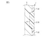
- FIG. 5 is a cross-sectional view showing another example of a vehicle garnish.
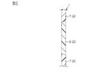
- FIG. 6 is a cross-sectional view showing another example of a vehicle garnish.
- FIG. 7 is a cross-sectional view showing another example of a vehicle garnish.
- FIG. 8 is a cross-sectional view showing another example of a vehicle garnish.
- the vehicle garnish 1 shown in FIG. 1 is an emblem of a vehicle and is provided at the front portion of the vehicle.
- a millimeter wave radar 2 is mounted on the front part of the vehicle as an in-vehicle sensor for transmitting and receiving electromagnetic waves for detecting an object outside the vehicle.
- the millimeter wave radar 2 transmits radio waves (millimeter waves) toward the outside of the vehicle (left side in FIG. 2), while receiving the millimeter waves reflected by hitting an object outside the vehicle and detecting an object outside the vehicle through transmission and reception of such millimeter waves. do.
- the vehicle garnish 1 is located on the front side (left side in FIG. 2) of the millimeter wave radar 2 in the millimeter wave transmission direction in order to make the millimeter wave radar 2 difficult to see from the outside of the vehicle.
- the vehicle garnish 1 is capable of transmitting the millimeter wave.
- FIG. 3 shows an enlarged portion of the vehicle garnish 1 surrounded by the alternate long and short dash line in FIG.
- the vehicle garnish 1 includes a base material 3 attached to the vehicle, a decorative layer 4 having a design, and a transparent layer 5 that covers the decorative layer 4 and makes it visible from the outside of the vehicle. I have.
- the base material 3, the decorative layer 4, and the transparent layer 5 are directed from the rear side (right side in FIG. 3) to the front side (left side in FIG. 3) in the millimeter wave transmission direction from the millimeter wave radar 2. It is located in this order.
- the base material 3 has an attachment portion such as a claw for attaching the vehicle garnish 1 to the vehicle.
- the base material 3 is made of a material capable of ensuring rigidity capable of realizing attachment of the vehicle garnish 1 to the vehicle via the attachment portion and transmitting millimeter waves. Examples of such a material include acrylonitrile, ethylene-propylene-diene, styrene (AES), acrylonitrile, styrene, acrylic rubber (ASA), and the like.
- the decorative layer 4 has a pattern area 6 and a background area 7.
- the pattern region 6 is formed of a resin containing metal particles as a pigment.
- the background region 7 is formed of a resin containing a pigment of a color that serves as a background for the pattern region 6. Since the resin forming the pattern region 6 contains metal particles as a pigment as described above, the metal particles impart a metal-like brilliance different from the conventional one to the pattern region 6.
- the pattern region 6 and the background region 7 of the decorative layer 4 are respectively located in the vehicle garnish 1 as shown in FIG. 1, for example, thereby giving the vehicle garnish 1 a design.
- the pattern region 6 and the background region 7 can also transmit millimeter waves.
- metal oxide particles or metal compound particles can also be adopted.
- titanium oxide particles are used as the metal particles.
- the metal particles are contained in the resin forming the pattern region 6 of the decorative layer 4 so that the dielectric constant of the resin is 3.0 farads per meter or less and the dielectric loss tangent is 0.01 or less. ing.
- polycarbonate (PC) As the resin forming the pattern region 6 and the background region 7 of the decorative layer 4, it is conceivable to use polycarbonate (PC) or the like.
- the transparent layer 5 (FIG. 3) is formed of a resin that is colorless and transparent or colored and transparent and is capable of transmitting millimeter waves. Examples of such a resin include polycarbonate.
- the hard coat layer 8 is formed on the outer surface of the vehicle in the transparent layer 5, that is, the surface on the front side in the millimeter wave transmission direction of the millimeter wave radar 2 (the surface on the left side in FIG. 3).
- the hard coat layer 8 is a layer for imparting chipping resistance to flying stones while the vehicle is running and light resistance to sunlight to the vehicle garnish 1.
- the hard coat layer 8 is formed by applying, for example, a surface treatment agent that imparts chipping resistance and light resistance to the surface of the transparent layer 5 on the front side in the transmission direction of millimeter waves.
- the portion corresponding to the pattern region 6 of the decorative layer 4 Is formed with a recess 9.
- the recess 9 is dented toward the front side in the transmission direction of the millimeter wave from the millimeter wave radar 2.
- the pattern region 6 of the decorative layer 4 is located corresponding to the recess 9 of the transparent layer 5, and is formed so as to fill the recess 9.
- the pattern region 6 (recess 9) is three-dimensionally shown from the outside of the vehicle, and the pattern region 6 is brilliant. It becomes possible to have.
- the background region 7 of the decorative layer 4 is located on the surface of the transparent layer 5 on the rear side in the transmission direction of the millimeter wave, corresponding to a portion other than the recess 9.
- the transparent layer 5, the decorative layer 4, and the base material 3 are formed in the order of the transparent layer 5, the decorative layer 4, and the base material 3 by a resin molding method such as injection molding. Will be done.
- a resin molding method such as injection molding.
- the decorative layer 4 is formed after the transparent layer 5 is formed, one of the pattern region 6 and the background region 7 of the decorative layer 4 is formed, and then the other is formed.
- the pattern region 6 of the decorative layer 4 is formed so as to fill the concave portion 9 of the transparent layer 5 in the portion corresponding to the concave portion 9. Further, the background region 7 of the decorative layer 4 is formed in a portion other than the portion corresponding to the recess 9 of the transparent layer 5. In the decorative layer 4 formed in this way, there is a step between the portion of the transparent layer 5 corresponding to the recess 9 (pattern region 6) and the portion other than the portion corresponding to the recess 9 (background region 7). The pattern area 6 and the background area 7 are formed so as not to occur.
- the front side surface (the left side surface in FIG. 3) of the transparent layer 5 in the transmission direction of the millimeter wave is resistant to chipping.
- the hard coat layer 8 is formed by applying a surface treatment agent that imparts light resistance.
- the hard coat layer 8 By applying the surface treatment agent, it is also possible to form the hard coat layer as follows by using a film (sheet) having chipping resistance and light resistance.
- the transparent layer 5, the decorative layer 4, and the base material 3 are sequentially formed on one side surface in the thickness direction of the film through a resin molding method such as injection molding, whereby the transmission direction of the millimeter wave in the transparent layer 5 A hard coat layer made of the above film is formed on the front surface of the film.
- a resin molding method such as injection molding
- the vehicle garnish 1 is provided with a decorative layer 4 which is formed differently from the conventional one. Therefore, the texture of the decorative layer 4 in the vehicle garnish 1, and more specifically, the brilliance of the pattern region 6 in the decorative layer 4 is different from the conventional one. That is, in the decorative layer 4, the pattern region 6 is formed of a resin containing metal particles as a pigment, while the background region 7 is formed of a resin containing a pigment of a background color. Since the decorative layer 4 is formed in a manner different from the conventional one in this way, the texture (brilliance) and the like of the decorative layer 4 can be made different from the conventional one, which is the garnish for vehicles. It is effective in making the design of 1 diverse.
- the pattern region of the decorative layer 4 is tentatively used by methods such as painting, film insert molding, and sputtering. If 6 is formed, the decorative layer 4 must be formed by a method different from that of the base material 3 and the transparent layer 5 formed of the resin. Therefore, when manufacturing the vehicle garnish 1, it is inevitable that the number of work steps for forming the decorative layer 4 increases, and the production of the vehicle garnish 1 requires labor and cost.
- the pattern region 6 of the decorative layer 4 is formed of a resin containing metal particles as a pigment
- the background region 7 of the decorative layer 4 is a pigment having a color that serves as the background of the pattern region 6.
- the decorative layer 4 can be formed by the same type of method as the base material 3 and the transparent layer 5 (in this example, injection molding). As a result, it is possible to suppress an increase in the number of work steps for forming the decorative layer 4, and it is possible to suppress the labor and cost required for manufacturing the vehicle garnish 1.
- the pattern region 6 (recessed portion 9) is three-dimensionally shown from the outside of the vehicle, and the pattern region 6 is brilliant. Can be given.
- the pattern region 6 of the decorative layer 4 is formed by a method such as painting, film insert molding, and sputtering, the pattern region 6 is formed on the inner surface of the recess 9 of the transparent layer 5 as shown in FIG. Formed thinly along. Therefore, the portion of the formed decorative layer 4 corresponding to the recess 9 of the transparent layer 5 (pattern region 6) and the portion of the decorative layer 4 other than the portion corresponding to the recess 9 (background region 7). There is a step between them. As a result, in the base material 3 formed after the decorative layer 4, the thickness of the portion corresponding to the recess 9 of the transparent layer 5 (the portion corresponding to the pattern region 6) is the portion other than the recess 9 of the transparent layer 5.
- the thickness of the base material 3 is thicker in the portion corresponding to the recess 9 of the transparent layer 5 than the portion other than the portion corresponding to the recess 9, it corresponds to the recess 9 of the transparent layer 5 in the base material 3.
- the heat shrinkage after formation becomes larger than the portion corresponding to the portion other than the recess 9, and a depression (so-called sink mark) is formed as shown by the alternate long and short dash line in FIG.
- the portion corresponding to the concave portion 9 of the transparent layer 5 and the concave portion 9 of the formed decorative layer 4 correspond to the concave portion 9.
- the pattern region 6 and the background region 7 can be formed so that a step is not generated between the portion and the portion other than the portion (FIG. 3). Therefore, the thickness of the portion of the base material 3 corresponding to the recess 9 of the transparent layer 5 is not thicker than the thickness of the portion of the transparent layer 5 other than the recess 9. Therefore, it is possible to suppress the occurrence of a depression (two-dot chain line in FIG. 4) due to heat shrinkage after formation as described above in the portion of the base material 3 corresponding to the recess 9 of the transparent layer 5.
- the metal particles contained in the resin forming the pattern region 6 of the decorative layer 4 As the amount of metal particles contained in the resin forming the pattern region 6 of the decorative layer 4 is increased, the brilliance like metal in the pattern region 6 becomes better, but the radio wave transmission in the pattern region 6 is improved. Sex is reduced.
- the metal particles are contained in the resin so that the dielectric constant of the resin forming the pattern region 6 is 3.0 farads per meter or less and the dielectric loss tangent is 0.01 or less. , The necessary radio wave transmission in the resin (pattern area 6) can be ensured.
- the resin forming the background region 7 of the decorative layer 4 has the rigidity required for mounting on the vehicle, and the resin forming the background region 7 has the vehicle garnish.
- a mounting portion such as a claw for mounting 1 to the vehicle is formed.
- a resin for example, a copolymerized polycarbonate may be adopted, or a resin having the characteristics of both PC and ABS, such as a PC / ABS polymer alloy, may be adopted.
- the resin forming the transparent layer 5 is said to have chipping resistance against flying stones while the vehicle is running and light resistance against sunlight.
- the transparent layer 5 By forming the transparent layer 5 with such a resin, it is not necessary to form the hard coat layer 8 (FIG. 3) on the front surface of the transparent layer 5 in the millimeter wave transmission direction as in the first embodiment.
- the resin for forming the transparent layer 5 for example, a copolymerized polycarbonate may be used.
- a mounting portion such as a claw for mounting the vehicle garnish to the vehicle can be formed in the background region 7 of the decorative layer 4. Therefore, it is not necessary to provide the base material 3 for attaching the vehicle garnish 1 to the vehicle on the rear side of the decorative layer 4 in the millimeter wave transmission direction. Since the base material 3 is not provided on the vehicle garnish 1, the thickness of the vehicle garnish 1 in the millimeter wave transmission direction can be reduced, and the electromagnetic wave transmission of the vehicle garnish 1 can be improved accordingly. Can be done.
- the hard coat layer 8 does not have to be formed on the front surface of the transparent layer 5 in the millimeter wave transmission direction, the thickness of the vehicle garnish 1 in the millimeter wave transmission direction is further reduced. be able to.
- the resin forming the pattern region 6 of the decorative layer 4 has chipping resistance to flying stones while the vehicle is running and light resistance to sunlight.
- a resin for example, a copolymerized polycarbonate can be considered.
- the resin forming the background region 7 of the decorative layer 4 is considered to have chipping resistance to flying stones while the vehicle is running, light resistance to sunlight, and rigidity necessary for mounting on the vehicle.
- a resin for example, a copolymerized polycarbonate can be considered.
- one of the pattern region 6 and the background region 7 of the decorative layer 4 is formed through injection molding or the like, and then the other is formed through injection molding or the like.
- the surface of the decorative layer 4 thus formed on the front side in the transmission direction of the millimeter wave is set so that a step does not occur between the pattern region 6 and the background region 7.
- the following effects can be obtained. (7) Since the pattern region 6 and the background region 7 of the decorative layer 4 can be provided with chipping resistance and light resistance, the chipping resistance and light resistance are on the front side of the decorative layer 4 in the transmission direction of the millimeter wave. It is not necessary to form the transparent layer 5 (FIG. 5) having the above. Therefore, since the transparent layer 5 and the base material 3 are not provided on the vehicle garnish 1, the thickness of the vehicle garnish 1 in the transmission direction of the millimeter wave can be further reduced, and the electromagnetic wave transmission of the vehicle garnish can be improved. It can be further improved.
- the vehicle garnish 1 of this embodiment has a structure in which the pattern region 6 of the decorative layer 4 is not covered by the transparent layer 5 as compared with that of the first embodiment (FIG. 3). The point is different.
- the transparent layer 5 is formed with a hole 5a penetrating the transparent layer 5 in the transmission direction of the millimeter wave, and the pattern region 6 of the decorative layer 4 penetrates the hole 5a in the transparent layer 5. It extends to the front surface in the transmission direction.
- the following effects can be obtained.
- the step between the pattern region 6 and the background region 7 of the decorative layer 4 becomes large, the step enables a deeper expression of the transmission direction of the millimeter wave.
- the content of the metal particles in the resin forming the pattern region 6 of the decorative layer 4 can be appropriately changed.
- titanium oxide particles are exemplified as the above metal particles, other metal particles may be adopted.
- the portion corresponding to the base material 3 (FIG. 3) in the first embodiment may be formed of the same material as the pattern region 6 of the decorative layer 4 as shown in FIG.
- the resin forming the pattern region 6 it is conceivable to adopt a resin having rigidity necessary for mounting on a vehicle, for example, a copolymerized polycarbonate.
- the recess 9 in the transparent layer 5 it is not always necessary to form the recess 9 in the transparent layer 5.
- the surface of the transparent layer 5 on the rear side in the transmission direction of the millimeter wave is formed into a flat surface without a step, and the pattern region 6 and the background region 7 of the decorative layer 4 are formed as in the third embodiment (FIG. 6). You may.
- the resin forming the transparent layer 5 may be, for example, polycarbonate, and the hard coat layer 8 as in the first embodiment may be formed on the transparent layer 5.
- the millimeter wave radar 2 as the in-vehicle sensor for transmitting and receiving electromagnetic waves
- an infrared sensor for transmitting and receiving infrared rays may be used as electromagnetic waves.
Landscapes
- Engineering & Computer Science (AREA)
- Radar, Positioning & Navigation (AREA)
- Remote Sensing (AREA)
- Physics & Mathematics (AREA)
- Mechanical Engineering (AREA)
- Computer Networks & Wireless Communication (AREA)
- General Physics & Mathematics (AREA)
- Electromagnetism (AREA)
- Vehicle Waterproofing, Decoration, And Sanitation Devices (AREA)
- Radar Systems Or Details Thereof (AREA)
- Vehicle Interior And Exterior Ornaments, Soundproofing, And Insulation (AREA)
Abstract
車両用ガーニッシュ(1)は、車外の物体を検出するための電磁波の送受信を行う車載センサにおける電磁波の送信方向の前方に設けられるように構成され、電磁波を透過させることが可能とされている。車両用ガーニッシュ(1)は、車外から見える加飾層(4)を備えている。加飾層(4)は、模様領域(6)および背景領域(7)を有している。模様領域(6)は、金属粒子を顔料として含む樹脂によって形成されている。背景領域(7)は、模様領域(6)の背景となる色の顔料を含む樹脂によって形成されている。
Description
本開示は、車両用ガーニッシュに関する。
自動車等の車両においては、車外の物体を検出するための電磁波の送受信を行う車載センサが設けられたものがある。そうした車両には、車載センサを車外から見えにくくするため、同車載センサにおける電磁波の送信方向の前方に、電磁波を透過させることが可能なエンブレム等の車両用ガーニッシュが設けられている。
特許文献1に示されるように、車両用ガーニッシュは、車両に取り付けられる基材、意匠性を有する加飾層、及び、その加飾層を覆いつつ車外から見えるようにする透明層を備えている。これら基材、加飾層、及び透明層は、車載センサからの電磁波の送信方向の後方側から前方側に向けて、この順に位置している。
車両用ガーニッシュの加飾層は、車外からの見栄えの点で重要な部分である。よって、高級感や質感を高めるために、該加飾層を、金属のような光輝性を有するように構成することが望まれている。このため、上記加飾層については、インジウム(In)等の金属材料を用いたスパッタリング等の方法によって、島構造を有する金属皮膜となるよう形成することが考えられる。
ところで、近年は車両用ガーニッシュに多様な意匠性が求められる傾向がある。よって、電磁波の透過性を持たせつつ加飾層の質感等を従来とは異なるものにすることが望まれている。
本開示の目的は、質感等が従来とは異なる加飾層を実現することができる車両用ガーニッシュを提供することにある。
上記課題を解決する車両用ガーニッシュは、車外の物体を検出するための電磁波の送受信を行う車載センサにおける電磁波の送信方向の前方に設けられるように構成され、電磁波を透過させることが可能とされており、且つ、車外から見える加飾層を備えている。加飾層は、模様領域および背景領域を有している。模様領域は、金属粒子を顔料として含む樹脂によって形成されている。背景領域は、模様領域の背景となる色の顔料を含む樹脂によって形成されている。
[第1実施形態]
以下、車両用ガーニッシュの第1実施形態について、図1~図4を参照して説明する。
図1に示す車両用ガーニッシュ1は、車両のエンブレムであって、同車両の前部に設けられている。また、車両の前部には、図2に示すように、車外の物体を検出するための電磁波の送受信を行う車載センサとして、ミリ波レーダ2が搭載されている。ミリ波レーダ2は、電波(ミリ波)を車外(図2の左側)に向けて送信する一方、車外の物体に当たって反射した上記ミリ波を受信し、そうしたミリ波の送受信を通じて車外の物体を検知する。
以下、車両用ガーニッシュの第1実施形態について、図1~図4を参照して説明する。
図1に示す車両用ガーニッシュ1は、車両のエンブレムであって、同車両の前部に設けられている。また、車両の前部には、図2に示すように、車外の物体を検出するための電磁波の送受信を行う車載センサとして、ミリ波レーダ2が搭載されている。ミリ波レーダ2は、電波(ミリ波)を車外(図2の左側)に向けて送信する一方、車外の物体に当たって反射した上記ミリ波を受信し、そうしたミリ波の送受信を通じて車外の物体を検知する。
車両用ガーニッシュ1は、ミリ波レーダ2を車外から見えにくくするため、同ミリ波レーダ2におけるミリ波の送信方向の前方側(図2の左方側)に位置している。車両用ガーニッシュ1は、上記ミリ波を透過させることが可能となっている。
図3は、車両用ガーニッシュ1における図2の二点鎖線で囲んだ部分を拡大して示している。図3から分かるように、車両用ガーニッシュ1は、車両に取り付けられる基材3、意匠性を有する加飾層4、及び、その加飾層4を覆いつつ車外から見えるようにする透明層5を備えている。基材3、加飾層4、及び透明層5は、ミリ波レーダ2からのミリ波の送信方向の後方側(図3の右方側)から前方側(図3の左方側)に向けて、この順に位置している。
次に、車両用ガーニッシュ1における基材3、加飾層4、及び透明層5について、個別に詳しく説明する。
[基材3]
基材3は、車両用ガーニッシュ1を車両に取り付けるための爪等の取付部を有している。基材3は、取付部を介した車両への車両用ガーニッシュ1の取り付けを実現することが可能な剛性を確保することができ、且つミリ波を透過させることができる材料によって形成されている。このような材料としては、例えばアクリロニトリル・エチレン-プロピレン-ジエン・スチレン(AES)や、アクリロニトリル・スチレン・アクリルゴム(ASA)等があげられる。
[基材3]
基材3は、車両用ガーニッシュ1を車両に取り付けるための爪等の取付部を有している。基材3は、取付部を介した車両への車両用ガーニッシュ1の取り付けを実現することが可能な剛性を確保することができ、且つミリ波を透過させることができる材料によって形成されている。このような材料としては、例えばアクリロニトリル・エチレン-プロピレン-ジエン・スチレン(AES)や、アクリロニトリル・スチレン・アクリルゴム(ASA)等があげられる。
[加飾層4]
加飾層4は、模様領域6および背景領域7を有している。模様領域6は、金属粒子を顔料として含む樹脂によって形成されている。背景領域7は、模様領域6の背景となる色の顔料を含む樹脂によって形成されている。模様領域6を形成する樹脂には上述したように金属粒子が顔料として含まれているため、その金属粒子によって模様領域6には従来とは異なる金属のような光輝性が付与される。加飾層4の模様領域6及び背景領域7はそれぞれ、車両用ガーニッシュ1において例えば図1に示すように位置しており、それによって車両用ガーニッシュ1に意匠性を持たせている。これら模様領域6及び背景領域7も、ミリ波を透過させることが可能となっている。
加飾層4は、模様領域6および背景領域7を有している。模様領域6は、金属粒子を顔料として含む樹脂によって形成されている。背景領域7は、模様領域6の背景となる色の顔料を含む樹脂によって形成されている。模様領域6を形成する樹脂には上述したように金属粒子が顔料として含まれているため、その金属粒子によって模様領域6には従来とは異なる金属のような光輝性が付与される。加飾層4の模様領域6及び背景領域7はそれぞれ、車両用ガーニッシュ1において例えば図1に示すように位置しており、それによって車両用ガーニッシュ1に意匠性を持たせている。これら模様領域6及び背景領域7も、ミリ波を透過させることが可能となっている。
上記模様領域6を形成する樹脂に含まれる金属粒子としては、金属酸化物粒子や金属化合物粒子を採用することも可能である。ちなみに、この例では上記金属粒子として酸化チタン粒子が用いられている。そして、この金属粒子が、加飾層4の模様領域6を形成する樹脂に対し、その樹脂の誘電率が3.0ファラド毎メートル以下、且つ誘電正接が0.01以下となるように含まれている。加飾層4の模様領域6及び背景領域7を形成する樹脂としては、ポリカーボネート(PC)等を採用することが考えられる。
[透明層5]
透明層5(図3)は、無色透明もしくは有色透明であってミリ波を透過させることが可能な樹脂によって形成されている。こうした樹脂としては、例えばポリカーボネートがあげられる。透明層5における車外側の面、すなわちミリ波レーダ2におけるミリ波の送信方向の前方側の面(図3の左方側の面)には、ハードコート層8が形成されている。ハードコート層8は、車両走行中の飛び石に対するチッピング耐性、及び、太陽光に対する耐光性を車両用ガーニッシュ1に持たせるための層である。ハードコート層8は、透明層5における上記ミリ波の送信方向の前方側の面に対し、例えば上記チッピング耐性及び耐光性を付与する表面処理剤を塗布することによって形成されている。
透明層5(図3)は、無色透明もしくは有色透明であってミリ波を透過させることが可能な樹脂によって形成されている。こうした樹脂としては、例えばポリカーボネートがあげられる。透明層5における車外側の面、すなわちミリ波レーダ2におけるミリ波の送信方向の前方側の面(図3の左方側の面)には、ハードコート層8が形成されている。ハードコート層8は、車両走行中の飛び石に対するチッピング耐性、及び、太陽光に対する耐光性を車両用ガーニッシュ1に持たせるための層である。ハードコート層8は、透明層5における上記ミリ波の送信方向の前方側の面に対し、例えば上記チッピング耐性及び耐光性を付与する表面処理剤を塗布することによって形成されている。
透明層5における車内側の面、すなわちミリ波レーダ2におけるミリ波の送信方向の後方側の面(図3の右方側の面)において、加飾層4の模様領域6に対応する部分には、凹部9が形成されている。凹部9は、ミリ波レーダ2からのミリ波の送信方向の前方側に向けてへこんでいる。言い換えれば、加飾層4の模様領域6は、透明層5の凹部9に対応して位置しており、その凹部9内を埋めるように形成されている。このように透明層5に加飾層4の模様領域6で埋められる凹部9を形成することにより、車外側から模様領域6(凹部9)を立体的に見せつつ、同模様領域6に光輝性を持たせることが可能となる。一方、加飾層4の背景領域7は、透明層5における上記ミリ波の送信方向の後方側の面において、凹部9以外の部分に対応して位置している。
次に、車両用ガーニッシュ1の形成手順について説明する。
車両用ガーニッシュ1を形成する際には、透明層5、加飾層4、及び基材3が、射出成形等の樹脂成形法により、透明層5、加飾層4、基材3の順に形成される。透明層5が形成された後に加飾層4が形成される際には、同加飾層4の模様領域6と背景領域7とのうち、一方が形成されてから他方が形成される。
車両用ガーニッシュ1を形成する際には、透明層5、加飾層4、及び基材3が、射出成形等の樹脂成形法により、透明層5、加飾層4、基材3の順に形成される。透明層5が形成された後に加飾層4が形成される際には、同加飾層4の模様領域6と背景領域7とのうち、一方が形成されてから他方が形成される。
加飾層4の模様領域6は、透明層5の凹部9に対応する部分に、同凹部9を埋めるように形成される。また、加飾層4の背景領域7は、透明層5の凹部9に対応する部分以外の部分に形成される。このように形成される加飾層4においては、透明層5の凹部9に対応する部分(模様領域6)と同凹部9に対応する部分以外の部分(背景領域7)との間に段差が生じないよう、それら模様領域6及び背景領域7が形成される。
透明層5、加飾層4、及び基材3が順に形成された後、透明層5における上記ミリ波の送信方向の前方側の面(図3の左方側の面)には、チッピング耐性及び耐光性を付与する表面処理剤を塗布することによってハードコート層8が形成される。
なお、表面処理剤の塗布によってハードコート層8を形成する代わりに、チッピング耐性及び耐光性を有するフィルム(シート)を用いて次のようにハードコート層を形成することも可能である。
すなわち、上記フィルムの厚さ方向の片側面に対し透明層5、加飾層4、基材3を射出成形等の樹脂成形法を通じて順に形成し、それによって透明層5における上記ミリ波の送信方向の前方側の面に上記フィルムからなるハードコート層を形成する。このようにハードコート層を形成する場合、表面処理剤の塗布を通じてハードコート層8を形成する場合と比較して、ハードコート層の形成にかかる手間を小さく抑えることができる。
次に、本実施形態の車両用ガーニッシュ1の作用効果について説明する。
(1)車両用ガーニッシュ1は、形成の仕方が従来とは異なる加飾層4を備えている。そのため、車両用ガーニッシュ1における加飾層4の質感等、詳しくは加飾層4における模様領域6の光輝性等が従来とは異なるものとなる。すなわち、上記加飾層4においては、模様領域6が金属粒子を顔料として含む樹脂によって形成されている一方、背景領域7が背景となる色の顔料を含む樹脂によって形成されている。このように従来とは異なる仕方で加飾層4が形成されているため、同加飾層4の質感(光輝性)等を従来とは異なるものとすることができ、そのことが車両用ガーニッシュ1の意匠性を多様なものとするうえで有効となる。
(1)車両用ガーニッシュ1は、形成の仕方が従来とは異なる加飾層4を備えている。そのため、車両用ガーニッシュ1における加飾層4の質感等、詳しくは加飾層4における模様領域6の光輝性等が従来とは異なるものとなる。すなわち、上記加飾層4においては、模様領域6が金属粒子を顔料として含む樹脂によって形成されている一方、背景領域7が背景となる色の顔料を含む樹脂によって形成されている。このように従来とは異なる仕方で加飾層4が形成されているため、同加飾層4の質感(光輝性)等を従来とは異なるものとすることができ、そのことが車両用ガーニッシュ1の意匠性を多様なものとするうえで有効となる。
(2)車両用ガーニッシュ1における加飾層4の模様領域6に金属のような光輝性を持たせるため、仮に塗装、フィルムインサート成形、及びスパッタリングといった方法を用いて、加飾層4の模様領域6を形成したとすると、その加飾層4については樹脂により形成される基材3及び透明層5とは別の方法で形成しなければならない。このため、車両用ガーニッシュ1を製造する際、加飾層4を形成する分の作業工程の数が多くなることは避けられず、車両用ガーニッシュ1の製造に手間とコストがかかるようになる。しかし、車両用ガーニッシュ1では、加飾層4の模様領域6が金属粒子を顔料として含む樹脂により形成され、且つ、加飾層4の背景領域7が模様領域6の背景となる色の顔料を含む樹脂によって形成されるため、加飾層4を基材3及び透明層5と同種類の方法(この例では射出成形)で形成することができる。その結果、加飾層4を形成する分の作業工程の数が多くなることを抑制でき、ひいては車両用ガーニッシュ1の製造に手間とコストがかかることを抑制できるようになる。
(3)透明層5に形成された凹部9を加飾層4の模様領域6で埋めることにより、車外側から模様領域6(凹部9)を立体的に見せつつ、同模様領域6に光輝性を持たせることができる。
ここで、加飾層4の模様領域6を仮に塗装、フィルムインサート成形、及びスパッタリングといった方法を用いて形成したとすると、図4に示すように模様領域6が透明層5の凹部9の内面に沿って薄く形成される。このため、形成された加飾層4における透明層5の凹部9に対応する部分(模様領域6)と、同加飾層4における凹部9に対応する部分以外の部分(背景領域7)との間に段差が生じる。その結果、加飾層4の後に形成される基材3において、透明層5の凹部9に対応する部分(模様領域6に対応する部分)の厚さが、透明層5の凹部9以外の部分に対応する部分(背景領域7に対応する部分)の厚さよりも厚くなる。このように基材3の厚さが透明層5の凹部9に対応する部分で同凹部9に対応する部分以外の部分よりも厚くなるため、基材3における透明層5の凹部9に対応する部分において、形成後の熱収縮が上記凹部9以外の部分に対応する部分よりも大きくなり、図4に二点鎖線で示すように窪み(いわゆるヒケ)が生じるようになる。
しかし、加飾層4の模様領域6と背景領域7とは共に樹脂によって形成されているため、形成された加飾層4における透明層5の凹部9に対応する部分と同凹部9に対応する部分以外の部分との間に段差が生じないよう、それら模様領域6と背景領域7とを形成することができる(図3)。このため、基材3における透明層5の凹部9に対応する部分の厚さが、透明層5の凹部9以外の部分に対応する部分の厚さよりも厚くなることはない。従って、基材3における透明層5の凹部9に対応する部分において、上述したように形成後の熱収縮に伴う窪み(図4の二点鎖線)が生じることを抑制できる。
(4)加飾層4の模様領域6を形成する樹脂に含まれる金属粒子の量を多くするほど、模様領域6における金属のような光輝性が良好にはなるものの、模様領域6における電波透過性は低下する。この点、模様領域6を形成する上記樹脂の誘電率が3.0ファラド毎メートル以下、且つ誘電正接が0.01以下となるように、上記金属粒子が上記樹脂に含まれるようにすることで、その樹脂(模様領域6)における必要な電波透過性を確保することができる。
[第2実施形態]
次に、車両用ガーニッシュの第2実施形態について、図5を参照して説明する。
図5に示すように、この実施形態の車両用ガーニッシュ1では、第1実施形態のもの(図3)に対し、基材3及びハードコート層8が省略されている。
次に、車両用ガーニッシュの第2実施形態について、図5を参照して説明する。
図5に示すように、この実施形態の車両用ガーニッシュ1では、第1実施形態のもの(図3)に対し、基材3及びハードコート層8が省略されている。
図5に示す車両用ガーニッシュ1では、加飾層4の背景領域7を形成する樹脂が車両に対する取り付けに必要な剛性を有するものとされており、その背景領域7を形成する樹脂に車両用ガーニッシュ1を車両に取り付けるための爪等の取付部が形成されている。こうした樹脂としては、例えば共重合ポリカーボネートを採用したり、PC/ABS系ポリマーアロイといったPCとABSとの両方の特徴を持った樹脂を採用したりすることが考えられる。
また、透明層5を形成する樹脂は、車両走行中の飛び石に対するチッピング耐性、及び、太陽光に対する耐光性を有するものとされている。こうした樹脂で透明層5を形成することにより、上記ミリ波の送信方向における透明層5の前方側の面に第1実施形態のようなハードコート層8(図3)を形成する必要がなくなる。なお、透明層5を形成するための上記樹脂としては、例えば共重合ポリカーボネートを採用することが考えられる。
本実施形態によれば、第1実施形態の(1)~(4)の効果に加え、以下に示す効果が得られるようになる。
(5)加飾層4の背景領域7に車両用ガーニッシュを車両に取り付けるための爪等の取付部を形成することができる。そのため、上記ミリ波の送信方向における加飾層4の後方側に、車両用ガーニッシュ1を車両に取り付けるための基材3を設けなくてもよくなる。そして、車両用ガーニッシュ1に基材3を設けない分、上記ミリ波の送信方向についての車両用ガーニッシュ1の厚みを薄くすることができ、その分車両用ガーニッシュ1の電磁波透過性を向上させることができる。
(5)加飾層4の背景領域7に車両用ガーニッシュを車両に取り付けるための爪等の取付部を形成することができる。そのため、上記ミリ波の送信方向における加飾層4の後方側に、車両用ガーニッシュ1を車両に取り付けるための基材3を設けなくてもよくなる。そして、車両用ガーニッシュ1に基材3を設けない分、上記ミリ波の送信方向についての車両用ガーニッシュ1の厚みを薄くすることができ、その分車両用ガーニッシュ1の電磁波透過性を向上させることができる。
(6)上記ミリ波の送信方向における透明層5の前方側の面にハードコート層8を形成しなくてもよい分、上記ミリ波の送信方向についての車両用ガーニッシュ1の厚みを更に薄くすることができる。
[第3実施形態]
次に、車両用ガーニッシュの第3実施形態について、図6を参照して説明する。
図6に示すように、この実施形態の車両用ガーニッシュ1では、第2実施形態のもの(図5)に対し透明層5が省略されている。
次に、車両用ガーニッシュの第3実施形態について、図6を参照して説明する。
図6に示すように、この実施形態の車両用ガーニッシュ1では、第2実施形態のもの(図5)に対し透明層5が省略されている。
図6に示す車両用ガーニッシュ1では、加飾層4の模様領域6を形成する樹脂が、車両走行中の飛び石に対するチッピング耐性、及び、太陽光に対する耐光性を有するものとされている。こうした樹脂としては、例えば共重合ポリカーボネートを採用することが考えられる。
更に、加飾層4の背景領域7を形成する樹脂は、車両走行中の飛び石に対するチッピング耐性、太陽光に対する耐光性、及び車両に対する取り付けに必要な剛性を有するものとされている。こうした樹脂としては、例えば共重合ポリカーボネートを採用することが考えられる。
上記車両用ガーニッシュ1を形成する際には、加飾層4の模様領域6と背景領域7とのうち、一方が射出成形等を通じて形成された後に他方が射出成形等を通じて形成される。こうして形成された加飾層4における上記ミリ波の送信方向の前方側の面は、模様領域6と背景領域7との間で段差が生じないようにされている。
本実施形態によれば、第2実施形態の効果に加え、以下に示す効果が得られるようになる。
(7)加飾層4の模様領域6及び背景領域7にチッピング耐性及び耐光性を持たせることができるため、加飾層4における上記ミリ波の送信方向の前方側に、チッピング耐性や耐光性を有する透明層5(図5)を形成しなくてもよくなる。従って、車両用ガーニッシュ1に透明層5及び基材3を設けない分、車両用ガーニッシュ1における上記ミリ波の送信方向についての厚みを更に薄くすることができ、ひいては車両用ガーニッシュの電磁波透過性を更に向上させることができる。
(7)加飾層4の模様領域6及び背景領域7にチッピング耐性及び耐光性を持たせることができるため、加飾層4における上記ミリ波の送信方向の前方側に、チッピング耐性や耐光性を有する透明層5(図5)を形成しなくてもよくなる。従って、車両用ガーニッシュ1に透明層5及び基材3を設けない分、車両用ガーニッシュ1における上記ミリ波の送信方向についての厚みを更に薄くすることができ、ひいては車両用ガーニッシュの電磁波透過性を更に向上させることができる。
[第4実施形態]
次に、車両用ガーニッシュの第4実施形態について、図7を参照して説明する。
図7に示すように、この実施形態の車両用ガーニッシュ1は、第1実施形態のもの(図3)に対し、加飾層4の模様領域6が透明層5によって覆われていない構造となっている点が異なっている。詳しくは、透明層5には上記ミリ波の送信方向に同透明層5を貫通する孔5aが形成されており、加飾層4の模様領域6が上記孔5aを貫通して透明層5における上記送信方向の前側の面まで延びている。
次に、車両用ガーニッシュの第4実施形態について、図7を参照して説明する。
図7に示すように、この実施形態の車両用ガーニッシュ1は、第1実施形態のもの(図3)に対し、加飾層4の模様領域6が透明層5によって覆われていない構造となっている点が異なっている。詳しくは、透明層5には上記ミリ波の送信方向に同透明層5を貫通する孔5aが形成されており、加飾層4の模様領域6が上記孔5aを貫通して透明層5における上記送信方向の前側の面まで延びている。
本実施形態によれば、第1実施形態の(1)、(2)、及び(4)の効果に加え、以下に示す効果が得られるようになる。
(8)加飾層4の模様領域6と背景領域7との間の段差が大きくなるため、その段差によって上記ミリ波の送信方向についてのより奥行きのある表現が可能となる。
(8)加飾層4の模様領域6と背景領域7との間の段差が大きくなるため、その段差によって上記ミリ波の送信方向についてのより奥行きのある表現が可能となる。
[その他の実施形態]
なお、上記各実施形態は、例えば以下のように変更することもできる。上記各実施形態及び以下の変更例は、技術的に矛盾しない範囲で互いに組み合わせて実施することができる。
なお、上記各実施形態は、例えば以下のように変更することもできる。上記各実施形態及び以下の変更例は、技術的に矛盾しない範囲で互いに組み合わせて実施することができる。
・加飾層4の模様領域6を形成する樹脂に対する金属粒子の含有量については適宜変更することが可能である。
・上記金属粒子として、酸化チタン粒子を例示したが、それ以外の金属粒子を採用してもよい。
・上記金属粒子として、酸化チタン粒子を例示したが、それ以外の金属粒子を採用してもよい。
・第1実施形態における基材3(図3)に相当する部分を、図8に示すように加飾層4の模様領域6と同じ材料で形成するようにしてもよい。この場合、模様領域6を形成する樹脂として、車両に対する取り付けに必要な剛性を有するもの、例えば共重合ポリカーボネートを採用することが考えられる。
・第1実施形態及び第2実施形態において、必ずしも透明層5に凹部9を形成する必要はない。例えば、透明層5における上記ミリ波の送信方向の後方側の面を段差のない平面状とし、加飾層4の模様領域6及び背景領域7を第3実施形態(図6)のように形成してもよい。
・第2実施形態において、透明層5を形成する樹脂を例えばポリカーボネートとし、その透明層5に第1実施形態のようなハードコート層8を形成してもよい。
・電磁波を送受信する車載センサとして、ミリ波レーダ2を用いる代わりに、電磁波として赤外線を送受信する赤外線センサを用いてもよい。
・電磁波を送受信する車載センサとして、ミリ波レーダ2を用いる代わりに、電磁波として赤外線を送受信する赤外線センサを用いてもよい。
Claims (6)
- 車外の物体を検出するための電磁波の送受信を行う車載センサにおける電磁波の送信方向の前方に設けられるように構成され、電磁波を透過させることが可能とされており、且つ、車外から見える加飾層を備えている車両用ガーニッシュにおいて、
前記加飾層は、模様領域および背景領域を有し、
前記模様領域は、金属粒子を顔料として含む樹脂によって形成されており、
前記背景領域は、前記模様領域の背景となる色の顔料を含む樹脂によって形成されていることを特徴とする車両用ガーニッシュ。 - 樹脂製の基材および樹脂製の透明層をさらに備え、
前記基材は、車両に取り付けられるように構成され、
前記加飾層は、前記基材における前記車載センサの電磁波の送信方向の前方側に位置し、
前記透明層は、前記加飾層における前記電磁波の送信方向の前方側に位置する請求項1に記載の車両用ガーニッシュ。 - 前記透明層は、前記電磁波の送信方向の前方側に向けてへこむ凹部を有し、
前記加飾層の模様領域は、前記透明層の前記凹部に対応して位置し、
前記加飾層の背景領域は、前記透明層における前記凹部以外の部分に対応して位置する請求項2に記載の車両用ガーニッシュ。 - 樹脂製の透明層をさらに備え、
前記透明層は、前記加飾層における前記電磁波の送信方向の前方側に位置し、
前記加飾層の背景領域を形成する樹脂は、車両に対する取り付けに必要な剛性を有するものとされている請求項1に記載の車両用ガーニッシュ。 - 前記加飾層の模様領域を形成する樹脂は、車両走行中の飛び石に対するチッピング耐性、及び、太陽光に対する耐光性を有するものとされており、
前記加飾層の背景領域を形成する樹脂は、車両走行中の飛び石に対するチッピング耐性、太陽光に対する耐光性、及び車両に対する取り付けに必要な剛性を有するものとされている請求項1に記載の車両用ガーニッシュ。 - 請求項1~5のいずれか一項に記載の車両用ガーニッシュにおいて、
前記電磁波として電波の送受信を行う車載センサにおける電波の送信方向の前方に設けられており、
前記金属粒子は、前記加飾層の模様領域を形成する樹脂に対し、その樹脂の誘電率が3.0ファラド毎メートル以下、且つ誘電正接が0.01以下となるように含まれている車両用ガーニッシュ。
Priority Applications (1)
| Application Number | Priority Date | Filing Date | Title |
|---|---|---|---|
| CN202180037035.0A CN115667975A (zh) | 2020-05-26 | 2021-04-22 | 车辆用装饰件 |
Applications Claiming Priority (2)
| Application Number | Priority Date | Filing Date | Title |
|---|---|---|---|
| JP2020-091130 | 2020-05-26 | ||
| JP2020091130A JP7384113B2 (ja) | 2020-05-26 | 2020-05-26 | 車両用ガーニッシュ |
Publications (1)
| Publication Number | Publication Date |
|---|---|
| WO2021241089A1 true WO2021241089A1 (ja) | 2021-12-02 |
Family
ID=78744444
Family Applications (1)
| Application Number | Title | Priority Date | Filing Date |
|---|---|---|---|
| PCT/JP2021/016265 Ceased WO2021241089A1 (ja) | 2020-05-26 | 2021-04-22 | 車両用ガーニッシュ |
Country Status (3)
| Country | Link |
|---|---|
| JP (2) | JP7384113B2 (ja) |
| CN (1) | CN115667975A (ja) |
| WO (1) | WO2021241089A1 (ja) |
Cited By (1)
| Publication number | Priority date | Publication date | Assignee | Title |
|---|---|---|---|---|
| DE102022121310A1 (de) | 2022-08-23 | 2024-02-29 | Bayerische Motoren Werke Aktiengesellschaft | Abdeckung für einen Radarsensor eines Fahrzeugs, Fahrzeug sowie Verfahren zur Herstellung einer Abdeckung für einen Radarsensor |
Families Citing this family (1)
| Publication number | Priority date | Publication date | Assignee | Title |
|---|---|---|---|---|
| JP2024123411A (ja) * | 2023-03-01 | 2024-09-12 | 豊田合成株式会社 | 近赤外線透過カバー及び近赤外線センサ |
Citations (6)
| Publication number | Priority date | Publication date | Assignee | Title |
|---|---|---|---|---|
| JP2010066152A (ja) * | 2008-09-11 | 2010-03-25 | Faltec Co Ltd | レドーム及びレドームの製造方法 |
| KR20170047070A (ko) * | 2015-10-22 | 2017-05-04 | 김병삼 | 고휘도 도료를 이용한 레이돔 및 이를 포함하는 자동차 |
| WO2018101165A1 (ja) * | 2016-11-30 | 2018-06-07 | 株式会社ファルテック | レーダカバー及びレーダカバーの製造方法 |
| WO2019078303A1 (ja) * | 2017-10-18 | 2019-04-25 | Ntn株式会社 | カバーおよび車載用フィン型アンテナ装置 |
| EP3709440A1 (en) * | 2019-03-13 | 2020-09-16 | Zanini Auto Grup, S.A. | Radome for vehicles and method for manufacturing said radome |
| JP2020147680A (ja) * | 2019-03-13 | 2020-09-17 | 三菱ケミカル株式会社 | ミリ波レーダーカバー用(メタ)アクリル樹脂組成物、ミリ波レーダーカバー、ミリ波レーダー装置、及び車両 |
Family Cites Families (11)
| Publication number | Priority date | Publication date | Assignee | Title |
|---|---|---|---|---|
| JP2007013722A (ja) | 2005-06-30 | 2007-01-18 | Toyoda Gosei Co Ltd | 電波レーダ装置のビーム経路に配置される樹脂成形品とその製造方法 |
| JP2011112596A (ja) | 2009-11-30 | 2011-06-09 | Toyota Motor Corp | レーダ装置ビーム経路内用成形品の製造方法およびレーダ装置ビーム経路内用成形品 |
| JP2014091819A (ja) | 2012-11-07 | 2014-05-19 | Panasonic Corp | 射出成形用樹脂組成物、射出成形品、加飾部品及びこれを用いた家電製品 |
| JP6111999B2 (ja) | 2013-11-29 | 2017-04-12 | トヨタ自動車株式会社 | 装飾被膜 |
| JP6552326B2 (ja) | 2015-08-07 | 2019-07-31 | 株式会社東海理化電機製作所 | 電波透過部品 |
| JP6658313B2 (ja) * | 2016-06-01 | 2020-03-04 | 豊田合成株式会社 | 車両用装飾部品 |
| JP6229781B2 (ja) | 2016-10-18 | 2017-11-15 | 三菱ケミカル株式会社 | ポリカーボネート樹脂組成物及び成形品 |
| JP7201368B2 (ja) | 2017-11-07 | 2023-01-10 | 三恵技研工業株式会社 | 車載レーダー装置用レドーム及びその製造方法 |
| JP7059867B2 (ja) * | 2018-08-22 | 2022-04-26 | 豊田合成株式会社 | 車両用装飾部品 |
| JP7042999B2 (ja) * | 2018-10-09 | 2022-03-29 | 豊田合成株式会社 | 電波透過カバー |
| JP2020067291A (ja) | 2018-10-22 | 2020-04-30 | 豊田合成株式会社 | 車載センサカバー |
-
2020
- 2020-05-26 JP JP2020091130A patent/JP7384113B2/ja active Active
-
2021
- 2021-04-22 CN CN202180037035.0A patent/CN115667975A/zh active Pending
- 2021-04-22 WO PCT/JP2021/016265 patent/WO2021241089A1/ja not_active Ceased
-
2023
- 2023-09-06 JP JP2023144357A patent/JP7505631B2/ja active Active
Patent Citations (6)
| Publication number | Priority date | Publication date | Assignee | Title |
|---|---|---|---|---|
| JP2010066152A (ja) * | 2008-09-11 | 2010-03-25 | Faltec Co Ltd | レドーム及びレドームの製造方法 |
| KR20170047070A (ko) * | 2015-10-22 | 2017-05-04 | 김병삼 | 고휘도 도료를 이용한 레이돔 및 이를 포함하는 자동차 |
| WO2018101165A1 (ja) * | 2016-11-30 | 2018-06-07 | 株式会社ファルテック | レーダカバー及びレーダカバーの製造方法 |
| WO2019078303A1 (ja) * | 2017-10-18 | 2019-04-25 | Ntn株式会社 | カバーおよび車載用フィン型アンテナ装置 |
| EP3709440A1 (en) * | 2019-03-13 | 2020-09-16 | Zanini Auto Grup, S.A. | Radome for vehicles and method for manufacturing said radome |
| JP2020147680A (ja) * | 2019-03-13 | 2020-09-17 | 三菱ケミカル株式会社 | ミリ波レーダーカバー用(メタ)アクリル樹脂組成物、ミリ波レーダーカバー、ミリ波レーダー装置、及び車両 |
Cited By (1)
| Publication number | Priority date | Publication date | Assignee | Title |
|---|---|---|---|---|
| DE102022121310A1 (de) | 2022-08-23 | 2024-02-29 | Bayerische Motoren Werke Aktiengesellschaft | Abdeckung für einen Radarsensor eines Fahrzeugs, Fahrzeug sowie Verfahren zur Herstellung einer Abdeckung für einen Radarsensor |
Also Published As
| Publication number | Publication date |
|---|---|
| JP7384113B2 (ja) | 2023-11-21 |
| JP7505631B2 (ja) | 2024-06-25 |
| CN115667975A (zh) | 2023-01-31 |
| JP2021188916A (ja) | 2021-12-13 |
| JP2023164517A (ja) | 2023-11-10 |
Similar Documents
| Publication | Publication Date | Title |
|---|---|---|
| JP2016182866A (ja) | 車両用装着品 | |
| JP4872886B2 (ja) | 電波レーダ装置のビーム経路に配置される樹脂成形品 | |
| US8974712B2 (en) | Method of manufacturing radome | |
| JP3755809B2 (ja) | 電波透過性外装部品及びその製造方法 | |
| EP3300169B1 (en) | Radar cover and method of manufacturing the radar cover | |
| JP5735196B2 (ja) | レドーム及びレドームの製造方法 | |
| JP7505631B2 (ja) | 車両用ガーニッシュ | |
| US11199609B2 (en) | Radar cover and method for manufacturing radar cover | |
| KR20170047070A (ko) | 고휘도 도료를 이용한 레이돔 및 이를 포함하는 자동차 | |
| JP2007013722A (ja) | 電波レーダ装置のビーム経路に配置される樹脂成形品とその製造方法 | |
| WO2018101165A1 (ja) | レーダカバー及びレーダカバーの製造方法 | |
| EP3933431A1 (en) | Radar cover | |
| US20240162603A1 (en) | Radome for vehicles | |
| US11592551B2 (en) | Radome for a radar sensor of a motor vehicle and motor vehicle | |
| CN112389053A (zh) | 车载传感器盖 | |
| JP7059867B2 (ja) | 車両用装飾部品 | |
| JP2008195161A (ja) | 車両の外装部品 | |
| JP2021104717A (ja) | 車両用外装品及び車両用外装品の製造方法 | |
| JP7063842B2 (ja) | レーダカバー及びレーダカバーの製造方法 | |
| JP7722499B1 (ja) | 電磁波透過性積層体 | |
| JP6809886B2 (ja) | レーダカバー及びレーダカバーの製造方法 | |
| JP7034123B2 (ja) | レーダカバー | |
| JP6954962B2 (ja) | レーダカバー及びレーダカバーの製造方法 | |
| US20240316594A1 (en) | Laminate | |
| KR20250043451A (ko) | 자동차 부품, 센서 장치, 자동차, 및 자동차 부품의 투과도를 개선하기 위한 방법 및 필름 세트 |
Legal Events
| Date | Code | Title | Description |
|---|---|---|---|
| 121 | Ep: the epo has been informed by wipo that ep was designated in this application |
Ref document number: 21813569 Country of ref document: EP Kind code of ref document: A1 |
|
| NENP | Non-entry into the national phase |
Ref country code: DE |
|
| 122 | Ep: pct application non-entry in european phase |
Ref document number: 21813569 Country of ref document: EP Kind code of ref document: A1 |