WO2021241045A1 - 信号処理装置、および信号処理方法、並びにプログラム - Google Patents
信号処理装置、および信号処理方法、並びにプログラム Download PDFInfo
- Publication number
- WO2021241045A1 WO2021241045A1 PCT/JP2021/015387 JP2021015387W WO2021241045A1 WO 2021241045 A1 WO2021241045 A1 WO 2021241045A1 JP 2021015387 W JP2021015387 W JP 2021015387W WO 2021241045 A1 WO2021241045 A1 WO 2021241045A1
- Authority
- WO
- WIPO (PCT)
- Prior art keywords
- azimuth
- azimuth estimation
- cluster
- unit
- signal processing
- Prior art date
- Legal status (The legal status is an assumption and is not a legal conclusion. Google has not performed a legal analysis and makes no representation as to the accuracy of the status listed.)
- Ceased
Links
Images








Classifications
-
- G—PHYSICS
- G01—MEASURING; TESTING
- G01S—RADIO DIRECTION-FINDING; RADIO NAVIGATION; DETERMINING DISTANCE OR VELOCITY BY USE OF RADIO WAVES; LOCATING OR PRESENCE-DETECTING BY USE OF THE REFLECTION OR RERADIATION OF RADIO WAVES; ANALOGOUS ARRANGEMENTS USING OTHER WAVES
- G01S13/00—Systems using the reflection or reradiation of radio waves, e.g. radar systems; Analogous systems using reflection or reradiation of waves whose nature or wavelength is irrelevant or unspecified
- G01S13/88—Radar or analogous systems specially adapted for specific applications
- G01S13/93—Radar or analogous systems specially adapted for specific applications for anti-collision purposes
- G01S13/931—Radar or analogous systems specially adapted for specific applications for anti-collision purposes of land vehicles
-
- G—PHYSICS
- G01—MEASURING; TESTING
- G01S—RADIO DIRECTION-FINDING; RADIO NAVIGATION; DETERMINING DISTANCE OR VELOCITY BY USE OF RADIO WAVES; LOCATING OR PRESENCE-DETECTING BY USE OF THE REFLECTION OR RERADIATION OF RADIO WAVES; ANALOGOUS ARRANGEMENTS USING OTHER WAVES
- G01S13/00—Systems using the reflection or reradiation of radio waves, e.g. radar systems; Analogous systems using reflection or reradiation of waves whose nature or wavelength is irrelevant or unspecified
- G01S13/02—Systems using reflection of radio waves, e.g. primary radar systems; Analogous systems
- G01S13/06—Systems determining position data of a target
- G01S13/42—Simultaneous measurement of distance and other co-ordinates
-
- G—PHYSICS
- G01—MEASURING; TESTING
- G01S—RADIO DIRECTION-FINDING; RADIO NAVIGATION; DETERMINING DISTANCE OR VELOCITY BY USE OF RADIO WAVES; LOCATING OR PRESENCE-DETECTING BY USE OF THE REFLECTION OR RERADIATION OF RADIO WAVES; ANALOGOUS ARRANGEMENTS USING OTHER WAVES
- G01S13/00—Systems using the reflection or reradiation of radio waves, e.g. radar systems; Analogous systems using reflection or reradiation of waves whose nature or wavelength is irrelevant or unspecified
- G01S13/02—Systems using reflection of radio waves, e.g. primary radar systems; Analogous systems
- G01S13/50—Systems of measurement based on relative movement of target
- G01S13/58—Velocity or trajectory determination systems; Sense-of-movement determination systems
-
- G—PHYSICS
- G01—MEASURING; TESTING
- G01S—RADIO DIRECTION-FINDING; RADIO NAVIGATION; DETERMINING DISTANCE OR VELOCITY BY USE OF RADIO WAVES; LOCATING OR PRESENCE-DETECTING BY USE OF THE REFLECTION OR RERADIATION OF RADIO WAVES; ANALOGOUS ARRANGEMENTS USING OTHER WAVES
- G01S13/00—Systems using the reflection or reradiation of radio waves, e.g. radar systems; Analogous systems using reflection or reradiation of waves whose nature or wavelength is irrelevant or unspecified
- G01S13/02—Systems using reflection of radio waves, e.g. primary radar systems; Analogous systems
- G01S13/50—Systems of measurement based on relative movement of target
- G01S13/58—Velocity or trajectory determination systems; Sense-of-movement determination systems
- G01S13/583—Velocity or trajectory determination systems; Sense-of-movement determination systems using transmission of continuous unmodulated waves, amplitude-, frequency-, or phase-modulated waves and based upon the Doppler effect resulting from movement of targets
- G01S13/584—Velocity or trajectory determination systems; Sense-of-movement determination systems using transmission of continuous unmodulated waves, amplitude-, frequency-, or phase-modulated waves and based upon the Doppler effect resulting from movement of targets adapted for simultaneous range and velocity measurements
-
- G—PHYSICS
- G01—MEASURING; TESTING
- G01S—RADIO DIRECTION-FINDING; RADIO NAVIGATION; DETERMINING DISTANCE OR VELOCITY BY USE OF RADIO WAVES; LOCATING OR PRESENCE-DETECTING BY USE OF THE REFLECTION OR RERADIATION OF RADIO WAVES; ANALOGOUS ARRANGEMENTS USING OTHER WAVES
- G01S13/00—Systems using the reflection or reradiation of radio waves, e.g. radar systems; Analogous systems using reflection or reradiation of waves whose nature or wavelength is irrelevant or unspecified
- G01S13/88—Radar or analogous systems specially adapted for specific applications
- G01S13/93—Radar or analogous systems specially adapted for specific applications for anti-collision purposes
- G01S13/931—Radar or analogous systems specially adapted for specific applications for anti-collision purposes of land vehicles
- G01S2013/9327—Sensor installation details
- G01S2013/93271—Sensor installation details in the front of the vehicles
Definitions
- the present disclosure relates to a signal processing device, a signal processing method, and a program. More specifically, the present invention relates to a signal processing device that executes object detection processing using radar, a signal processing method, and a program.
- a moving device such as an autonomous vehicle or a robot detects an object that becomes an obstacle in the traveling direction, secures a safe traveling route, and travels.
- Radar is often used for object detection processing.
- Patent Document 1 Japanese Unexamined Patent Publication No. 2010-054344
- Patent Document 2 Japanese Unexamined Patent Publication No. 2010-054344
- the process of calculating the direction (azimuth angle) of an object has a problem that the processing cost is high and the processing delay is likely to occur. In robots and autonomous vehicles traveling at high speeds, such processing delays are fatal and may cause accidents such as collision with obstacles.
- the present disclosure solves such a problem, and is a signal processing device that efficiently executes calculation processing of the direction (azimuth) of an object to perform object detection and analysis with reduced delay, and signal processing.
- the purpose is to provide methods as well as programs.
- the first aspect of this disclosure is An azimuth estimation area selection unit that inputs a speed range map showing the distance and relative speed of the object that reflected the radar wave and selects the azimuth estimation target area from the input speed range map.
- the signal processing apparatus has an azimuth estimation unit that executes azimuth estimation for the selected area selected by the azimuth estimation area selection unit.
- the second aspect of the present disclosure is It is a signal processing method executed in a signal processing device.
- the azimuth estimation area selection unit inputs a speed range map showing the distance and relative speed of the object that reflected the radar wave, and selects the azimuth estimation target area from the input speed range map, and the azimuth estimation area selection step.
- An azimuth estimation step in which the azimuth estimation unit executes azimuth estimation for the selected area selected in the azimuth estimation area selection step. It is in the signal processing method to be executed.
- the third aspect of the present disclosure is A program that executes signal processing in a signal processing device.
- An azimuth estimation area selection step for inputting a speed range map showing the distance and relative speed of an object reflecting radar waves to the azimuth estimation area selection unit and selecting an azimuth estimation target area from the input speed range map.
- An azimuth estimation step for causing the azimuth estimation unit to execute azimuth estimation for the selected area selected in the azimuth estimation area selection step. It is in the program to be executed.
- the program of the present disclosure is, for example, a program that can be provided by a storage medium or a communication medium provided in a computer-readable format to an information processing device or a computer system capable of executing various program codes.
- a program can be provided by a storage medium or a communication medium provided in a computer-readable format to an information processing device or a computer system capable of executing various program codes.
- system is a logical set configuration of a plurality of devices, and the devices of each configuration are not limited to those in the same housing.
- an azimuth estimation area selection unit that inputs a speed range map showing the distance and relative speed of an object that reflects radar waves and selects an azimuth estimation target area from the input speed range map, and selection. It has an azimuth estimation unit that performs azimuth estimation for only a region.
- the azimuth estimation area selection unit detects clusters that are a collection of bright spots satisfying predetermined conditions from the speed range map, and selects the detected clusters as the azimuth estimation target area.
- an aggregate of bright spots having a specified number or more and a specified density or more or a cluster corresponding to a specific object type is selected as an azimuth estimation target area.
- a device and a method for performing azimuth estimation with only an object area or a specific type of object area as an azimuth estimation target area are realized. It should be noted that the effects described in the present specification are merely exemplary and not limited, and may have additional effects.
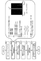
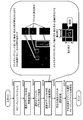
- FIG. It is a figure explaining the process executed by the selection area limited azimuth angle estimation part. It is a figure which shows the flowchart explaining the processing sequence executed by the azimuth angle estimation area selection part of the signal processing apparatus (millimeter wave radar apparatus) of this disclosure. It is a figure explaining the structural example of the signal processing apparatus (millimeter wave radar apparatus) of Example 2 of this disclosure. It is a figure explaining the structure and processing of the azimuth angle estimation object selection part of Example 2.
- FIG. It is a figure explaining the process to execute by a clustering processing part. It is a figure explaining the process to execute the selection object limited azimuth angle estimation part.
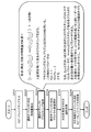
- FIG. 2 It is a figure which shows the flowchart explaining the processing sequence executed by the azimuth angle estimation area selection part of the signal processing apparatus (millimeter wave radar apparatus) of Embodiment 2 of this disclosure. It is a figure explaining the specific processing example when the azimuth angle estimation target object is a vehicle. It is a figure explaining the specific processing example when the azimuth angle estimation target object is a vehicle. It is a figure explaining the specific processing example when the azimuth angle estimation target object is a vehicle. It is a figure explaining the specific processing example when the azimuth angle estimation target object is a vehicle.
- a moving device such as an autonomous vehicle or a robot detects an object that becomes an obstacle in the traveling direction, secures a safe traveling route, and travels.
- Radar is often used for object detection processing.
- FIG. 1 is a diagram illustrating an outline of an object detection process using a radar.
- FIG. 1 (1) shows a state in which the vehicle A equipped with the radar detects the vehicle B in front by using the radar.
- FIG. 1 (2) is a diagram showing details of a radar transmission / reception configuration.
- Millimeter-wave radar As a radar that executes object detection processing, for example, a millimeter-wave radar having a wavelength in the mm unit of 30 to 300 GHz is widely used. Millimeter-wave radar has many advantages such as high straightness, ease of securing a wide band width, high resistance to environmental changes, and a large amount of information, and is widely used.
- the signal processing apparatus of the present disclosure described below will also be described as a signal processing apparatus using a millimeter wave radar.
- the signal processing device of the present disclosure is not limited to the millimeter-wave radar, and may be configured by using a radar in another wavelength band.
- FIG. 1 (2) is a diagram illustrating a process in which the signal processing device (millimeter wave radar) 100 of the vehicle A of FIG. 1 (1) detects the distance and the direction (azimuth) of the vehicle B in front.
- the signal processing device (millimeter wave radar) 100 detects the distance and the direction (azimuth) of the vehicle B in front.
- the transmitted wave output from the transmitting antenna of the signal processing device (millimeter wave radar) 100 reaches the vehicle B, that is, the detection target object 20, the transmitted wave is reflected by the vehicle B. Then, it is received by a plurality of receiving antennas of the signal processing device (millimeter wave radar) 100.
- the signal processing device (millimeter wave radar) 100 has a plurality of (for example, n) receiving antennas. Since each of these plurality of receiving antennas has a different installation position, the reception timing of the received wave will be different. That is, each receiving antenna receives received waves having different phases.
- the distance and direction (azimuth) of the object to be detected 20 are analyzed by radar wave analysis processing by the signal processing device (millimeter wave radar) 100 having such a configuration. Specifically, as shown in FIG. 1 (2), the following processing is performed.
- the object distance is calculated from the transmission / reception time of the radar wave.
- the direction (azimuth) of the object is calculated based on the phase difference between the antennas of the received wave.
- the azimuth angle of the object is an angle between a predetermined reference line extending from the signal processing device (millimeter wave radar) 100 and a straight line connecting the signal processing device (millimeter wave radar) 100 and the object.
- the straight line connecting the vehicle A and the object (vehicle B) is the angle between the reference line and the reference line (0 °) in the straight direction of the vehicle A.
- the vehicle B that is, the object to be detected 20 is on this reference line.
- the azimuth angle of the vehicle B, that is, the object to be detected 20 is 0 °.
- the azimuth angle of the vehicle B, that is, the object 20 to be detected is + 30 °. ..
- the azimuth angle of the vehicle B, that is, the object 20 to be detected is + 45 °. ..
- the azimuth angle of the vehicle B, that is, the object 20 to be detected is ⁇ 30 °.
- FIG. 4 is a diagram showing a configuration example of a conventional signal processing device (millimeter wave radar device) 100.
- the signal processing device (millimeter wave radar device) 100 shown in FIG. 4 includes a transmission wave generator (synthesizer) 101, a transmission antenna 102, a plurality of (n) receiving antennas 103-1 to n, and a plurality (n) for each of the receiving antennas. It has mixers 104-1 to 104-1 to n, AD converters 105-1 to n, FFT106-1 to n, an azimuth estimation unit 107, and a detection object analysis unit 108.
- the transmission wave generation unit (synthesizer) 101 generates a millimeter-wave radar signal to be transmitted via the transmission antenna 102.
- the millimeter wave radar signal is a radar signal in the 30 to 300 GHz band having a wavelength in millimeters.
- Millimeter-wave radar has many advantages such as high straightness, ease of securing a wide band width, high resistance to environmental changes, and a large amount of information.
- the millimeter wave radar signal generated by the transmission wave generation unit (synthesizer) 101 is transmitted via the transmission antenna 102.
- the millimeter-wave radar signal transmitted via the transmitting antenna 102 is reflected by various objects and received by a plurality of (n) receiving antennas 103-1 to n.
- the figure shows an example of a reflected wave of only one object to be detected 20, in reality, the receiving antennas 103-1 to a plurality of (n) reflected waves from a large number of various objects are shown. Received by n.
- the plurality of (n) receiving antennas 103-1 to n are set at different positions as described above with reference to FIG. 1, even if the detection target objects 20 have the same reflection position, a plurality of (n) receiving antennas 103-1 to n (n) are set.
- the received signals of the receiving antennas 103-1 to n of n) are signals having different phases.
- the received signals of the plurality of (n) receiving antennas 103-1 to n are input to the mixers 104-1 to n in the subsequent stage, respectively.
- the mixers 104-1 to n calculate the difference signal between the received signal of each of the received antennas 103-1 to n and the transmitted signal generated by the transmitted wave generator (synthesizer) 101.
- the difference signals generated by the mixers 104-1 to n are input to the AD converters 105-1 to n and converted into digital signals. It is a digital signal showing the difference between the received signal of each of the receiving antennas 103-1 to n and the transmission signal generated by the transmission wave generation unit (synthesizer) 101.
- the digital signals generated by the AD converters 105-1 to n are input to the subsequent FFT106-1 to n, respectively.
- Each of FFT106-1 to n performs a fast Fourier transform (Fast Fourier Transform) of the digital signal generated by the AD converters 105-1 to n, and performs a signal conversion process for converting the time domain signal into the frequency domain signal.
- FFT106-1 to n performs a fast Fourier transform (Fast Fourier Transform) of the digital signal generated by the AD converters 105-1 to n, and performs a signal conversion process for converting the time domain signal into the frequency domain signal.
- Each of the FFT 106-1 to n performs a fast Fourier transform (FFT) process of the digital signal generated by the AD converters 105-1 to n, and the speed range maps 51-1 to n are displayed as shown in the figure. Output.
- FFT fast Fourier transform
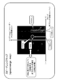
- the speed range map is shown in FIG.
- the horizontal axis is the speed of the object (the speed relative to the signal processing device (radar)).
- the vertical axis is the distance to the object (distance from the signal processing device (radar)) It is a map in which these values are set as orthogonal axes.
- the object is an object that reflects radar waves.
- the bright spots (white dots) on the map shown in the figure are the points indicating the speed (Km / h) and the distance (m) of the detected object.
- each of the bright spots is based on one reflection part (speed, distance) of the object calculated based on the transmission / reception signal of the radar.
- the object is a car
- a collection of a plurality of bright spots. (Cluster) is formed. The larger the object, the larger the cluster that is the collection of more bright spots.
- This cluster x is an object that is 65 m away and is approaching at 15 km / h. From such cluster characteristics, it is possible to estimate that the cluster x is a vehicle in front that is traveling at a lower speed of 15 km than the own vehicle equipped with the signal processing device 100.
- Object speed + 45km / h
- This cluster y is an object that continuously exists 0 to 65 m ahead and approaches at 45 km / h. From such cluster characteristics, it is possible to estimate that the cluster y is a side wall of the traveling path of the own vehicle (running at 45 km / h) equipped with the signal processing device 100.
- each of the plurality (n) FFT106-1 to n has a received signal of each of the receiving antennas 103-1 to n and a transmission signal generated by the transmission wave generator (synthesizer) 101.
- a fast Fourier transform (FFT) process based on a digital signal indicating a difference is executed, and a plurality (n) speed range maps 51-1 to n are output.
- These plurality (n) speed range maps 51-1 to n are input to the azimuth angle estimation unit 107.
- the azimuth estimation unit 107 is a fast Fourier transform (fast Fourier transform) based on a plurality of (n) speed range maps 51-1 to n, that is, a digital signal indicating a difference from the transmission signal generated by the transmission wave generation unit (synthesizer) 101.
- the direction (azimuth) of the detected object is estimated using a plurality of (n) speed range maps 51-1 to n generated by the FFT).
- the azimuth estimation unit 107 generates one azimuth (azimuth angle) range map 52 by the azimuth angle estimation process of the object using a plurality of (n) speed range maps 51-1 to n.
- FIG. 6 shows a specific example of the azimuth (azimuth angle) range map 52 generated by the azimuth estimation unit 107.
- the azimuth range map is shown in FIG. Azimuth of the object on the horizontal axis (angle indicating the object direction (direction))
- the vertical axis is the distance to the object (distance from the signal processing device (radar)) It is a map in which these values are set as orthogonal axes.
- the object is an object that reflects radar waves.
- the bright spots (white spots) on the map shown in the figure are the points indicating the azimuth angle (°) and the distance (m) of the detected object.
- each of the bright spots is based on one reflection part (azimuth angle, distance) of the object calculated based on the transmission / reception signal of the radar, and the speed range map described above with reference to FIG. 5 is used.
- a collection (cluster) of a plurality of bright spots is set.
- the cluster z is a cluster corresponding to an object located 65 m away and at an azimuth angle of -10 °.
- the azimuth estimation unit 107 generates an azimuth range map that can analyze the azimuth angle and distance of the project.
- the azimuth range map generated by the azimuth estimation unit 107 is input to the detection object analysis unit 108. Further, the speed range maps 51-1 to n generated by each of the FFT 106-1 to n are also input to the detection object analysis unit 108.
- the detected object analysis unit 108 executes object analysis processing using these maps. For example, execute object analysis processing such as what each of the clusters, which is a collection of bright spots detected from each map, is, for example, whether it is a car, a person, a wall, or a pole. Then, the final output (detection object analysis information) 53 is output.
- This cluster z is a cluster corresponding to an object located at an azimuth angle of ⁇ 10 ° at a distance of 65 m.
- the detection object analysis unit 108 executes the object analysis process using the speed range map and the azimuth (azimuth) range map. For example, execute object analysis processing such as what each of the clusters, which is a collection of bright spots detected from each map, is, for example, whether it is a car, a person, a wall, or a pole. Then, the final output (detection object analysis information) 53 is output.
- a problem in the configuration of the signal processing device (millimeter wave radar device) 100 shown in FIG. 4 is the processing cost of the azimuth angle estimation process in the azimuth angle estimation unit 107.
- the azimuth estimation unit 107 inputs a plurality (n) speed range maps 51-1 to n generated by a plurality (n) FFT106-1 to n, and a plurality (n) of these speed range maps 51-1 to n are input. ), The speed range maps 51-1 to n are analyzed, and one azimuth (azimuth angle) range map 52 is generated by the azimuth estimation process.
- the process of calculating the direction (azimuth) of this object has a problem that the processing cost is high and the processing delay is likely to occur. In robots and autonomous vehicles traveling at high speeds, such processing delays are fatal and may cause accidents such as collision with obstacles.
- FIG. 7 shows one speed range map 51.
- the azimuth estimation unit 107 Since the azimuth estimation unit 107 also estimates the azimuth angle for the bright spots in the region where the bright spot density is estimated to have no object in the speed range map 51, the processing cost increases, that is, the processing. The time becomes long, and the resources such as the processor and the memory required for the processing also become large. As a result, problems such as processing delay and the inability to use resources such as a processor and memory for other data processing occur.
- the signal processing apparatus of the present disclosure solves this problem.
- the signal processing apparatus of the present disclosure has a configuration that solves the above-mentioned problem, that is, the problem that the processing cost of the azimuth estimation process is excessive, and enables efficient azimuth estimation processing.
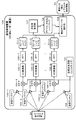
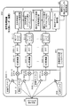
- FIG. 8 is a diagram showing a configuration example of the signal processing device (millimeter wave radar device) 200 of the first embodiment of the present disclosure.
- the signal processing device (millimeter-wave radar device) 200 of the present disclosure shown in FIG. 8 has a transmission wave generation unit (synthesizer) 201, a transmission antenna 202, a plurality of (n) receiving antennas 203-1 to n, and a receiving antenna for each.
- the configuration and processing of the transmission wave generators (synthesizers) 201 to FFT206-1 to n are the transmission wave generators (synthesizers) 201 to of the signal processing apparatus (millimeter wave radar apparatus) 100 described above with reference to FIG.
- the configuration and processing of FFT206-1 to n are the same.
- the azimuth estimation area selection unit 207 and the selection area limited azimuth angle estimation unit 208 are unique to the signal processing device (millimeter wave radar device) 200 of the present disclosure.
- the detection object analysis unit 209 performs substantially the same processing as the detection object analysis unit 108 of the signal processing device (millimeter wave radar device) 100 described with reference to FIG.
- the transmission wave generation unit (synthesizer) 201 generates a millimeter wave radar signal to be transmitted via the transmission antenna 202.
- the millimeter wave radar signal generated by the transmission wave generation unit (synthesizer) 201 is transmitted via the transmission antenna 202.
- the millimeter-wave radar signal transmitted via the transmitting antenna 202 is reflected by various objects and received by a plurality of (n) receiving antennas 203-1 to n.
- the figure shows an example of a reflected wave of only one object to be detected 20, in reality, the receiving antennas 203-1 to have a plurality of (n) reflected waves from a large number of various objects. Received by n.
- the received signals of the receiving antennas 203-1 to n of n) are signals having different phases.
- the received signals of the plurality of (n) receiving antennas 203-1 to n are input to the mixers 204-1 to n in the subsequent stage, respectively.
- the mixers 204-1 to n calculate the difference signal between the received signal of each of the received antennas 203-1 to n and the transmitted signal generated by the transmitted wave generator (synthesizer) 201.
- the difference signals generated by the mixers 204-1 to n are input to the AD converters 205-1 to n and converted into digital signals. It is a digital signal showing the difference between the received signal of each of the receiving antennas 203-1 to n and the transmission signal generated by the transmission wave generation unit (synthesizer) 201.
- the digital signals generated by the AD converters 205-1 to n are input to the FFT206-1 to n in the subsequent stage, respectively.
- Each of FFT206-1 to n performs a fast Fourier transform (Fast Fourier Transform) of the digital signal generated by the AD converters 205-1 to n, and performs a signal conversion process for converting the time domain signal into the frequency domain signal.
- FFT206-1 to n performs a fast Fourier transform (Fast Fourier Transform) of the digital signal generated by the AD converters 205-1 to n, and performs a signal conversion process for converting the time domain signal into the frequency domain signal.
- Each of the FFTs 206-1 to n performs a fast Fourier transform (FFT) process of the digital signal generated by the AD converters 205-1 to n to obtain speed range maps 51-1 to n as shown in the figure. Output.
- FFT fast Fourier transform
- the speed range map 51 output by the FFT 206 is a map described above with reference to FIG. 5, and as shown in FIG. 5,
- the horizontal axis is the speed of the object (the speed relative to the signal processing device (radar)).
- the vertical axis is the distance to the object (distance from the signal processing device (radar)) It is a map in which these values are set as orthogonal axes.
- the object is an object that reflects radar waves.
- the bright spots (white spots) on the map shown in FIG. 5 are the spots indicating the speed (Km / h) and the distance (m) of the detected object.
- each bright spot in the speed range map is based on one reflection part of the object calculated based on the transmission / reception signal of the radar (speed, distance). For example, when the object is a car, a collection (cluster) of a plurality of bright spots is set.
- the signal processing device 200 of the present disclosure inputs speed range maps 51-1 to n generated by each of FFT206-1 to n to the azimuth estimation area selection unit 207. do.
- the azimuth estimation area selection unit 207 performs a process of selecting an area (pixel area) for which the azimuth estimation process should be executed for each of the speed range maps 51-1 to n output by each of the FFTs 206-1 to n.
- the speed range maps 51-1 to n generated by each of the FFT 106-1 to n are input to the azimuth estimation unit 107. Since the azimuth estimation unit 107 also estimates the azimuth angle for all the bright spots of the speed range map, that is, the bright spots in the region where the object is estimated to be absent, the processing cost increases, the processing delay, etc. There was a problem of generating.
- the azimuth estimation area selection unit 207 of the present disclosure shown in FIG. 8 is a region (pixel area) in which the azimuth estimation process should be executed for each of the speed range maps 51-1 to n generated by each of FFT206-1 to n. Is performed, and "azimuth estimation area selection speed range maps 81-1 to n" indicating the selection area (pixel area) for which the azimuth estimation process should be executed are generated, and the selection area is limited to the next stage. Input to the azimuth estimation unit 208.
- the selection area limited azimuth estimation unit 208 uses the “azimuth estimation area selection speed range maps 81-1 to n” to cover only the area (pixel area) selected by the azimuth estimation area selection unit 207. Execute azimuth estimation processing. That is, the selection area limited azimuth estimation unit 208 does not execute the azimuth estimation process for all the bright spots distributed in each of the speed range maps 51-1 to n generated by each of FFT206-1 to n, but the azimuth. The azimuth estimation process only needs to be executed for the bright spots in the area (pixel area) selected by the angle estimation area selection unit 207, and the azimuth estimation process can be efficiently executed in a short time. Become.
- the azimuth estimation area selection unit 207 has an obstacle such as a vehicle, a wall, a person, etc. in the traveling direction of the own vehicle for each of the speed range maps 51-1 to n generated by each of FFT206-1 to n.
- "Azimuth estimation area selection speed range map 81-1 to” showing the cluster areas of objects estimated to be objects and these selected cluster areas as the selection area (pixel area) for which azimuth estimation should be performed.
- n is generated and input to the selection area limited azimuth estimation unit 208 of the next stage.
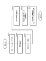
- the azimuth estimation area selection unit 207 includes a speed range map input unit 251, a feature amount extraction unit 252, a clustering processing unit 253, a cluster representative value selection unit 254, and an azimuth angle estimation cluster selection unit 255. ..
- the speed range map input unit 251 inputs each of the speed range maps 51-1 to n generated by each of the FFT 206-1 to n and transfers them to the feature amount extraction unit 252.
- the feature amount extraction unit 252 extracts the feature amount from each of the speed range maps 51-1 to n generated by each of the FFTs 206-1 to n.
- the speed range map is a map described above with reference to FIG.
- the horizontal axis is the speed of the object (the speed relative to the signal processing device (radar)).
- the vertical axis is the distance to the object (distance from the signal processing device (radar)) It is a map in which these values are set as orthogonal axes.
- the object is an object that reflects radar waves.
- the bright spots (white spots) on the map shown in FIG. 5 are the spots indicating the speed (Km / h) and the distance (m) of the detected object.
- the feature amount extraction unit 252 extracts a feature amount effective for selecting a region (pixel region) for performing azimuth estimation from this speed range map. Specifically, for example, a feature amount useful for extracting an obstacle object such as a vehicle in front of the own vehicle, a person, or a building such as a wall or a pillar is extracted. For example, a feature amount of a bright spot distribution indicating whether or not a predetermined number or more of bright spots are accumulated at a predetermined density or higher is extracted. A set of bright spots (clusters) in which more than a specified number of bright spots are accumulated at a specified density or higher is a region that is highly likely to be an obstacle object such as a person or a building such as a wall or pillar. The quantity extraction unit 252 extracts, for example, a feature quantity that makes such a region distinguishable.
- the feature amount extraction algorithm in the feature amount extraction unit 252 it is preferable to use an algorithm that considers periodicity, satisfaction of distance axioms, appropriate number of dimensions, properties of clustering algorithm, and the like.
- the feature amount extraction unit 252 extracts the feature amount from each of the speed range maps 51-1 to n generated by each of the FFT 206-1 to n, and each of the speed range maps 51-1 to n and the feature extracted from each map. The amount is output to the clustering processing unit 253.
- the clustering processing unit 253 applies each of the speed range maps 51-1 to n input from the feature amount extraction unit 252 and the feature amount extracted from each map to each of the bright spots of the speed range maps 51-1 to n. Perform clustering.
- a region having a feature amount of a bright spot distribution having a specified number or more and a specified density or more is set as a cluster having a feature amount corresponding to an obstacle object such as a person or a building such as a wall or a pillar.
- Perform clustering processing As a clustering algorithm, for example, an algorithm such as DBSCAN (Density-Based Splittering of Applications with Noise) can be applied.
- DBSCAN Density-Based Splittering of Applications with Noise
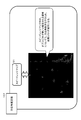
- FIG. 10 is a diagram showing a specific example of the clustering process in the clustering process unit 253. As shown in FIG. 10, a region having a feature amount of a bright spot distribution having a specified number or more and a specified density or more is set as a cluster.
- the speed range maps 51-1 to n in which the cluster is set are then input to the cluster representative value selection unit 254.
- the cluster representative value selection unit 254 acquires the representative value in the cluster set by the clustering processing unit 253.
- the speed range map is The horizontal axis is the speed of the object (the speed relative to the signal processing device (radar)).
- the vertical axis is the distance to the object (distance from the signal processing device (radar)) It is a map that can acquire each of these values (speed, distance).
- the object is an object that reflects radar waves.
- the cluster representative value selection unit 254 acquires the representative value of the cluster size and (speed, distance) set by the clustering processing unit 253. This representative value is used to determine what kind of object-compatible cluster the cluster is.
- the speed obtained as the representative value of the cluster differs depending on the object type corresponding to the cluster, such as in the case of a building such as a wall, in the case of a person, or in the case of a vehicle, and the object can be identified from the cluster representative value.
- the object identification corresponding to each cluster is executed by the detection object analysis unit 209.
- the detection object analysis unit 209 can perform highly accurate object identification by using the cluster representative value or the like.
- the speed range map in which the cluster including the cluster representative value set by the cluster representative value selection unit 254 is set as attribute data is input to the azimuth estimation cluster selection unit 255.
- the azimuth estimation cluster selection unit 255 performs a process of selecting an azimuth estimation target area, specifically, an azimuth estimation target cluster from a speed range map in which a cluster including a cluster representative value as attribute data is set.
- the azimuth estimation cluster selection unit 255 may, for example, select all of the clusters set by the clustering processing unit 253 based on the feature amount as the azimuth angle estimation target area (cluster).
- the clustering processing unit 253 based on the cluster representative values set by the cluster representative value selection unit 254, only the clusters having the representative values satisfying the predetermined conditions are set as the azimuth estimation target area (cluster). You may choose.
- the azimuth estimation cluster selection unit 255 selects all or some of the clusters set by the clustering processing unit 253 based on the feature amount as the azimuth estimation target area (cluster), and estimates the azimuth angle.
- a speed range map showing the target area (cluster), that is, "azimuth estimation area selection speed range maps 81-1 to n" is generated, and the generated map is sent to the next selection area limited azimuth angle estimation unit 208. input.
- the azimuth estimation area selection unit 207 generates "azimuth angle estimation area selection speed range maps 81-1 to n" including the selection information of the cluster for which the azimuth angle is to be estimated, and creates the generated map. , Is input to the next selection area limited azimuth estimation unit 208.
- the selection area limited azimuth estimation unit 208 inputs "azimuth estimation area selection speed range maps 81-1 to n" from the azimuth estimation area selection unit 207, and "azimuth angle estimation area selection speed range map 81-1". With reference to the azimuth estimation target cluster selection information of "n", the azimuth estimation process is executed only for the selected cluster area.
- the orientation is targeted only at the bright spots of the pixel region belonging to the cluster selected by the azimuth angle estimation area selection unit 207 as the azimuth angle estimation target area. Execute the angle estimation process. By estimating the azimuth angle only in such a limited area, it is possible to efficiently estimate the azimuth angle in a short time.
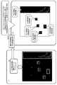
- FIG. 11 is a diagram illustrating a specific example of the azimuth angle estimation process executed by the selection area limited azimuth angle estimation unit 208.
- FIG. 11 (1) is a diagram showing an example of the azimuth estimation area selection speed range map 81 generated by the azimuth angle estimation area selection unit 207.
- the azimuth estimation area selection speed range map 81 clearly shows the azimuth estimation target cluster (rectangular area).
- FIG. 11 (2) is a diagram illustrating a cluster region for azimuth estimation in the azimuth estimation process executed by the selection region limited azimuth estimation unit 208.
- the selection area limited azimuth estimation unit 208 selects only the bright spots belonging to the azimuth estimation target areas a to e (clusters a to e) shown in FIG. 11 (2) and performs the azimuth estimation process.
- the azimuth estimation process targeting only such a limited area enables efficient and short-time processing.
- the selected area limited azimuth estimation unit 208 executes the azimuth estimation process targeting only the limited cluster area, generates the selected area limited azimuth (azimuth) range map 82, and detects the generated map. Output to the object analysis unit 209.
- the selection area-limited azimuth (azimuth) range map 82 generated by the selection area-limited azimuth estimation unit 208 is similar to the azimuth (azimuth) range map described above with reference to FIG.
- Azimuth of the object on the horizontal axis (angle indicating the object direction (direction))
- the vertical axis is the distance to the object (distance from the signal processing device (radar)) It is a map in which these values are set as orthogonal axes.
- the object is an object that reflects radar waves.
- the bright spots (white spots) on the map shown in FIG. 6 are the points indicating the azimuth angle (°) and the distance (m) of the detection object.
- the selected area limited azimuth estimation unit 208 executes the azimuth estimation process targeting only the limited cluster area of the speed range map, calculates the estimated azimuth angle of the limited cluster area, and makes the azimuth (azimuth) range map. To generate. Therefore, the selection area limited azimuth (azimuth angle) range map 82 generated by the selection area limited azimuth estimation unit 208 does not include azimuth estimation information other than the limited cluster area.
- the detection object analysis unit 209 has a selection area-limited azimuth range map 82 generated by the selection area-limited azimuth estimation unit 208, and the detection object analysis unit 209 has speeds generated by each of FFT206-1 to n.
- the range maps 51-1 to n are input, and the object analysis process using these maps is executed. For example, execute object analysis processing such as what each of the clusters, which is a collection of bright spots detected from each map, is, for example, whether it is a car, a person, a wall, or a pole. Then, the final output (detection object analysis information) 83 is output.
- the azimuth estimation area selection unit 207 includes a region (cluster) to be estimated for the azimuth angle, for example, an object that can be an obstacle.
- the cluster area is selected, and the azimuth estimation area selection speed range map 81 with the selected cluster specified is generated.
- the selection area limited azimuth estimation unit 208 inputs the azimuth estimation area selection speed range map 81 that specifies the selection cluster, and the azimuth estimation area selection unit 207 performs azimuth estimation using only the selected cluster as the processing target. conduct. As a result, efficient azimuth estimation becomes possible.
- control unit data processing unit
- CPU central processing unit
- Step S101 The azimuth estimation area selection unit 207 of the signal processing device (millimeter wave radar device) 200 shown in FIG. 8 first inputs a speed range map in step S101.
- This process is a process executed by the speed range map input unit 251 of the azimuth angle estimation area selection unit 207 shown in FIG.
- the speed range map input unit 251 inputs each of the speed range maps 51-1 to n generated by each of the FFT 206-1 to n of the signal processing device 200 shown in FIG.
- Step S102 the azimuth estimation area selection unit 207 executes the feature amount extraction process from each of the speed range maps 51-1 to n in step S102.
- This process is a process executed by the feature amount extraction unit 252 of the azimuth angle estimation area selection unit 207 shown in FIG.
- the feature amount extraction unit 252 extracts a feature amount effective for selecting a region (pixel region) for performing azimuth estimation from the speed range map. Specifically, for example, a feature amount useful for extracting an obstacle object such as a vehicle in front of the own vehicle, a person, or a building such as a wall or a pillar is extracted. For example, a feature amount of a bright spot distribution indicating whether or not a specified number or more of bright spots are accumulated at a specified density or higher is extracted.
- Step S103 the azimuth estimation area selection unit 207 executes a clustering process in step S103.
- This process is a process executed by the clustering process unit 253 of the azimuth angle estimation area selection unit 207 shown in FIG.
- the clustering processing unit 253 applies each of the speed range maps 51-1 to n input from the feature amount extraction unit 252 and the feature amount extracted from each map to each of the bright spots of the speed range maps 51-1 to n. Perform clustering. Specifically, for example, a region having a feature amount of a bright spot distribution having a specified number or more and a specified density or more is set as a cluster having a feature amount corresponding to an obstacle object such as a person or a building such as a wall or a pillar. Perform clustering processing.
- Step S104 the azimuth estimation area selection unit 207 executes the cluster representative value selection process in step S104.
- This process is a process executed by the cluster representative value selection unit 254 of the azimuth angle estimation area selection unit 207 shown in FIG.
- the cluster representative value selection unit 254 acquires the representative value in the cluster set by the clustering processing unit 253.
- the cluster representative value selection unit 254 acquires representative values such as the size and (speed, distance) of the cluster set by the clustering processing unit 253. This representative value is used to determine what kind of object-compatible cluster the cluster is.
- Steps S105 to S106 the azimuth estimation area selection unit 207 executes the azimuth estimation cluster selection process in step S105, and generates the azimuth estimation area selection speed range map in step S106.
- the azimuth estimation cluster selection unit 255 selects all or some of the clusters set by the clustering processing unit 253 based on the feature amount as the azimuth estimation target area (cluster), and the azimuth estimation target area (cluster). ) Is generated, that is, "azimuth angle estimation area selection speed range maps 81-1 to n".
- the generated map is input to the next selection area limited azimuth estimation unit 208.
- the selection area limited azimuth estimation unit 208 inputs "azimuth estimation area selection speed range maps 81-1 to n" to estimate the azimuth angle of "azimuth estimation area selection speed range maps 81-1 to n".
- the azimuth estimation process is executed only for the selected cluster area by referring to the cluster selection information. By performing the azimuth estimation process using only the limited area as the azimuth estimation target area, it is possible to efficiently estimate the azimuth in a short time.
- only a specific type of object is selected from obstacles such as a specific type of object, for example, only a vehicle or only a pedestrian, and the configuration area of the cluster corresponding to the selected object is selected. This is an example in which only the azimuth angle is estimated.
- FIG. 13 is a diagram showing a configuration example of the signal processing device (millimeter wave radar device) 300 of the second embodiment of the present disclosure.
- the signal processing device (millimeter wave radar device) 300 of the present disclosure shown in FIG. 13 has a transmission wave generation unit (synthesizer) 301, a transmission antenna 302, a plurality of (n) reception antennas 303-1 to n, and a reception antenna for each.
- the configuration and processing of the transmitted wave generators (synthesizers) 301 to FFT306-1 to n are described above with reference to FIG. 4 in the signal processing apparatus (millimeter wave radar apparatus) 100 transmitted wave generators (synthesizers) 301 to.
- the configuration and processing of FFT306-1 to n are the same.
- the azimuth estimation object selection unit 307 and the selection object limited azimuth angle estimation unit 308 have a configuration unique to the signal processing device (millimeter wave radar device) 300 of the second embodiment.
- the detection object analysis unit 309 performs almost the same processing as the detection object analysis unit 108 of the signal processing device (millimeter wave radar device) 100 described with reference to FIG.
- the transmission wave generation unit (synthesizer) 301 generates a millimeter wave radar signal to be transmitted via the transmission antenna 302.
- the millimeter wave radar signal generated by the transmission wave generation unit (synthesizer) 301 is transmitted via the transmission antenna 302.
- the millimeter-wave radar signal transmitted via the transmitting antenna 302 is reflected by various objects and received by a plurality of (n) receiving antennas 303-1 to n.
- the figure shows an example of a reflected wave of only one object to be detected 30, in reality, the receiving antennas 303-1 to a plurality of (n) reflected waves from a large number of various objects are shown. Received by n.
- the plurality of (n) receiving antennas 303-1 to n are set at different positions as described above with reference to FIG. 1, even if the detection target objects 30 have the same reflection position, a plurality of (n) receiving antennas 303-1 to n (n) are set.
- the received signals of the receiving antennas 303-1 to n of n) are signals having different phases.
- the received signals of the plurality of (n) receiving antennas 303-1 to n are input to the mixers 304-1 to n in the subsequent stage, respectively.
- the mixers 304-1 to n calculate the difference signal between the received signal of each of the received antennas 303-1 to n and the transmitted signal generated by the transmitted wave generator (synthesizer) 301.
- the difference signals generated by the mixers 304-1 to n are input to the AD converters 305-1 to n and converted into digital signals. It is a digital signal showing the difference between the received signal of each of the receiving antennas 303-1 to n and the transmission signal generated by the transmission wave generation unit (synthesizer) 301.
- the digital signals generated by the AD converters 305-1 to n are input to the subsequent FFT306-1 to n, respectively.
- Each of FFT306-1 to n performs a fast Fourier transform (Fast Fourier Transform) of the digital signal generated by the AD converters 305-1 to n, and performs a signal conversion process for converting the time domain signal into the frequency domain signal.
- FFT306-1 to n performs a fast Fourier transform (Fast Fourier Transform) of the digital signal generated by the AD converters 305-1 to n, and performs a signal conversion process for converting the time domain signal into the frequency domain signal.
- Each of the FFT 306-1 to n performs a fast Fourier transform (FFT) process of the digital signal generated by the AD converters 305-1 to n, and the speed range maps 51-1 to n are displayed as shown in the figure. Output.
- FFT fast Fourier transform
- the speed range map 51 output by the FFT 306 is a map described above with reference to FIG. 5, and as shown in FIG. 5,
- the horizontal axis is the speed of the object (the speed relative to the signal processing device (radar)).
- the vertical axis is the distance to the object (distance from the signal processing device (radar)) It is a map in which these values are set as orthogonal axes.
- the object is an object that reflects radar waves.
- the bright spots (white spots) on the map shown in FIG. 5 are the spots indicating the speed (Km / h) and the distance (m) of the detected object.
- each bright spot in the speed range map is based on one reflection part of the object calculated based on the transmission / reception signal of the radar (speed, distance). For example, when the object is a car, a collection (cluster) of a plurality of bright spots is set.
- the signal processing device 300 of the present disclosure inputs speed range maps 51-1 to n generated by each of FFT306-1 to n into the azimuth estimation object selection unit 307. do.
- the azimuth estimation object selection unit 307 sets an area (pixel area) for which the azimuth estimation process should be executed for each of the speed range maps 51-1 to n generated by each of the FFT 306-1 to n as an object area of a specific type. , For example, a process of selecting a specific type of object area such as "vehicle” or "person” is performed. The object type to be selected is determined in advance.
- the azimuth estimation object selection unit 307 of the present disclosure shown in FIG. 13 has, for example, a “vehicle” region (pixel region) for each of the speed range maps 51-1 to n generated by each of the FFT 306-1 to n. ) Is selected as the azimuth estimation target area, and the “human” area (pixel area) is selected as the azimuth estimation target area.
- the azimuth estimation object selection unit 307 further generates "azimuth estimation object selection speed range maps 91-1 to n" indicating an object area (pixel area) for which the azimuth estimation process should be executed, and the next stage. Output to the selected object limited azimuth angle estimation unit 308.
- the selected object limited azimuth estimation unit 308 uses the "azimuth estimation object selection speed range maps 91-1 to n" to select a specific type of object area (pixel area) selected by the azimuth estimation object selection unit 307. Performs azimuth estimation processing only for.
- the selected object limited azimuth estimation unit 308 does not execute the azimuth estimation process for all the bright spots distributed in each of the speed range maps 51-1 to n generated by each of FFT306-1 to n, but the azimuth.
- the azimuth estimation process only needs to be executed for the bright spots belonging to the specific type of object area (pixel area) selected by the angle estimation object selection unit 307, and the azimuth estimation process is efficiently executed in a short time. It becomes possible.
- the azimuth estimation object selection unit 307 has, for example, a vehicle, a wall, a person, etc. in the traveling direction of the own vehicle for each of the speed range maps 51-1 to n generated by each of the FFT306-1 to n. , For objects presumed to be obstacles, select cluster areas corresponding to one type or multiple types of objects, and use these selected cluster areas as the selected area (pixel area) for which azimuth estimation should be performed.
- the "azimuth angle estimation object selection speed range maps 91-1 to n" shown as are generated and output to the selection object limited azimuth angle estimation unit 308 in the next stage.
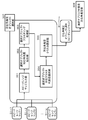
- the azimuth estimation object selection unit 307 includes a speed range map input unit 351, a selection object-compatible feature amount extraction unit 352, a selection object clustering processing unit 353, a selection object-compatible cluster representative value selection unit 354, and an orientation. It has an angle estimation cluster selection unit 355.
- the speed range map input unit 351 inputs each of the speed range maps 51-1 to n generated by each of FFT306-1 to n and transfers them to the feature amount extraction unit 352 corresponding to the selected object.
- the feature amount extraction unit 352 corresponding to the selected object extracts the feature amount corresponding to the selected object from each of the speed range maps 51-1 to n generated by each of the FFT306-1 to n.
- the speed range map is a map described above with reference to FIG.
- the horizontal axis is the speed of the object (the speed relative to the signal processing device (radar)).
- the vertical axis is the distance to the object (distance from the signal processing device (radar)) It is a map in which these values are set as orthogonal axes.
- the object is an object that reflects radar waves.
- the bright spots (white spots) on the map shown in FIG. 5 are the spots indicating the speed (Km / h) and the distance (m) of the detected object.
- the feature amount extraction unit 352 corresponding to the selected object extracts a feature amount effective for selecting a specific object for which the azimuth estimation should be performed, for example, a vehicle area (pixel area) from this speed range map.
- the feature amount useful for extracting the vehicle is extracted. For example, in order to determine whether or not a set of bright spots in which a specified number or more of bright spots are accumulated at a specified density or higher has a value estimated to be a vehicle in the speed and distance information of the set of bright spots. Extract the feature amount of effective bright spots. That is, the feature amount corresponding to the selected object type is extracted.
- the feature amount extraction unit 352 corresponding to the selected object extracts the feature amount from each of the speed range maps 51-1 to n generated by each of FFT306-1 to n, and from each of the speed range maps 51-1 to n and each map.
- the extracted feature amount is output to the clustering processing unit 353.
- the selection object clustering processing unit 353 applies each of the speed range maps 51-1 to n input from the selection object corresponding feature amount extraction unit 352 and the feature amounts extracted from each map to the speed range maps 51-1 to n. Clustering each bright spot is performed.
- a clustering process is executed in which a specific object for which azimuth estimation is to be performed, for example, a region having a feature amount effective for selecting a vehicle region (pixel region) is set as an azimuth estimation cluster. ..
- FIG. 15 is a diagram showing a specific example of the clustering process in the selected object clustering process unit 353.
- the example shown in FIG. 15 is an example of a clustering process in which a cluster having a feature amount effective for selecting a specific object for performing azimuth estimation, for example, a vehicle region (pixel region) is set.
- the rectangular area shown in the map shown on the right side of FIG. 15 is a cluster of areas presumed to be vehicles.
- the speed range maps 51-1 to n in which the cluster is set are input to the selected object-corresponding cluster representative value selection unit 354.
- the selected object-corresponding cluster representative value selection unit 354 acquires the representative value in the cluster set by the selected object clustering processing unit 353.
- the speed range map is The horizontal axis is the speed of the object (the speed relative to the signal processing device (radar)).
- the vertical axis is the distance to the object (distance from the signal processing device (radar)) It is a map that can acquire each of these values (speed, distance).
- the object is an object that reflects radar waves.
- the selected object-compatible cluster representative value selection unit 354 acquires representative values such as the size and (speed, distance) of the cluster set by the selected object clustering processing unit 353. This representative value is used to determine whether the cluster can be determined to be a cluster corresponding to the type of selected cluster, eg, the area of the car.
- the speed range map in which the cluster including the cluster representative value set by the selected object-compatible cluster representative value selection unit 354 is set as attribute data is input to the azimuth estimation cluster selection unit 355.
- the azimuth estimation cluster selection unit 355 performs a process of selecting an azimuth estimation target area, specifically, an azimuth estimation target cluster from a speed range map in which a cluster including a cluster representative value as attribute data is set.
- the azimuth estimation cluster selection unit 355 may select, for example, all of the clusters set by the selection object clustering processing unit 353 based on the feature amount as the azimuth angle estimation target area (cluster).
- the azimuth estimation target is only the cluster having the representative value satisfying the predetermined condition from the cluster set by the selected object clustering processing unit 353 based on the cluster representative value set by the selected object corresponding cluster representative value selection unit 354. It may be selected as an area (cluster).
- the azimuth estimation cluster selection unit 355 selects all or a part of the clusters set by the selection object clustering processing unit 353 based on the feature amount as the azimuth estimation target area (cluster), and the azimuth is oriented.
- a speed range map showing the angle estimation target area (cluster), that is, "azimuth estimation object selection speed range maps 91-1 to n" is generated, and the generated map is used as the next selection object limited azimuth angle estimation unit. Enter in 308.
- the azimuth estimation object selection unit 307 generates "azimuth estimation object selection speed range maps 91-1 to n" including the selection information of the cluster for which the azimuth is to be estimated, and creates the generated map. , The next selected object is input to the limited azimuth estimation unit 308.
- the selected object limited azimuth estimation unit 308 inputs "azimuth estimation object selection speed range maps 91-1 to n" from the azimuth estimation object selection unit 307, and "azimuth angle estimation object selection speed range map 91-1". With reference to the azimuth estimation target cluster selection information of "n", the azimuth estimation process is executed only for the selected cluster area.
- the azimuth estimation process is executed only for the bright spots in the pixel region to which the azimuth belongs. By estimating the azimuth angle only in such a limited area, it is possible to efficiently estimate the azimuth angle in a short time.
- FIG. 16 is a diagram illustrating a specific example of the azimuth angle estimation process executed by the selected object limited azimuth angle estimation unit 308.
- FIG. 16 (1) is a diagram showing an example of the azimuth estimation object selection speed range map 91 generated by the azimuth angle estimation object selection unit 307.
- the azimuth estimation object selection speed range map 91 clearly shows the azimuth estimation target cluster (rectangular area) corresponding to a specific type of object, for example, a vehicle object.
- FIG. 16 (2) is a diagram illustrating a cluster region for azimuth estimation in the azimuth estimation process executed by the selected object limited azimuth estimation unit 308.
- the selected object limited azimuth estimation unit 308 selects only the azimuth estimation target regions p to s shown in FIG. 16 (2) and performs the azimuth estimation process.
- the azimuth angle estimation target area p to s shown in FIG. 16 (2) is a cluster corresponding to a specific type of object, for example, a vehicle object.
- the selected object limited azimuth estimation unit 308 performs azimuth estimation processing targeting only the object area of a specific liquor, such as a cluster corresponding to a vehicle object. This enables efficient and short-time processing.
- the selected object limited azimuth estimation unit 308 executes the azimuth estimation process targeting only the limited cluster area corresponding to the specific object type, and generates the selected object limited azimuth (azimuth) range map 92. , The generated map is output to the detection object analysis unit 309.
- the selected object limited azimuth (azimuth) range map 92 generated by the selected object limited azimuth estimation unit 308 is similar to the azimuth (azimuth) range map described above with reference to FIG.
- Azimuth of the object on the horizontal axis (angle indicating the object direction (direction))
- the vertical axis is the distance to the object (distance from the signal processing device (radar)) It is a map in which these values are set as orthogonal axes.
- the object is an object that reflects radar waves.
- the bright spots (white spots) on the map shown in FIG. 6 are the points indicating the azimuth angle (°) and the distance (m) of the detection object.
- the selected object limited azimuth estimation unit 308 executes the azimuth estimation process targeting only the limited cluster area of the speed range map, calculates the estimated azimuth of the limited cluster area, and makes the azimuth (azimuth) range map. To generate. Therefore, the selected object limited azimuth (azimuth) range map 92 generated by the selected object limited azimuth estimation unit 308 does not include azimuth estimation information other than the limited cluster area such as a cluster corresponding to a vehicle object.
- the detection object analysis unit 309 has a selection object limited azimuth range map 92 generated by the selection object limited azimuth estimation unit 308, and the detection object analysis unit 309 has speeds generated by each of FFT306-1 to n.
- the range maps 51-1 to n are input, the object analysis process using these maps is executed, and the final output (detection object analysis information) 93 is output.
- the region (cluster) for which the azimuth is estimated is specified as a specific type such as a vehicle object.
- the azimuth estimation object selection speed range map 91 is selected as the cluster corresponding to the object of, and the selection cluster is specified.
- the selected object limited azimuth estimation unit 308 inputs the azimuth estimation object selection speed range map 91 in which the azimuth estimation object selection unit 307 specifies the selected cluster, and the azimuth estimation is performed using only the selected cluster as the processing target. conduct. As a result, efficient azimuth estimation becomes possible.
- control unit data processing unit
- CPU central processing unit
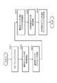
- Step S201 The azimuth estimation object selection unit 307 of the signal processing device (millimeter wave radar device) 300 shown in FIG. 13 first inputs a speed range map in step S201.
- This process is a process executed by the speed range map input unit 351 of the azimuth angle estimation object selection unit 307 shown in FIG.
- the speed range map input unit 351 inputs each of the speed range maps 51-1 to n generated by each of the FFT 306-1 to n of the signal processing device 300 shown in FIG.
- step S202 the azimuth estimation object selection unit 307 executes the selection object corresponding feature amount extraction process from each of the speed range maps 51-1 to n.
- This process is a process executed by the feature amount extraction unit 352 corresponding to the selected object of the azimuth angle estimation object selection unit 307 shown in FIG.
- the feature amount extraction unit 352 corresponding to the selected object extracts a feature amount effective for selecting a specific object for which the azimuth estimation is to be performed, for example, a vehicle area (pixel area) from the speed range map.
- the feature amount useful for extracting the vehicle is extracted. For example, in order to determine whether or not a set of bright spots in which a specified number or more of bright spots are accumulated at a specified density or higher has a value estimated to be a vehicle in the speed and distance information of the set of bright spots. Extract the feature amount of effective bright spots.
- Step S203 the azimuth estimation object selection unit 307 executes the selection object clustering process in step S203.
- This process is a process executed by the selection object clustering processing unit 353 of the azimuth angle estimation object selection unit 307 shown in FIG.
- the selection object clustering processing unit 353 applies each of the speed range maps 51-1 to n input from the selection object corresponding feature amount extraction unit 352 and the selection object corresponding feature amount extracted from each map to the speed range map 51-. Clustering of bright spots 1 to n is performed.
- a clustering process is executed in which a specific object for which azimuth estimation is to be performed, for example, a region having a feature amount effective for selecting a vehicle region (pixel region) is set as an azimuth estimation cluster. do.
- Step S204 the azimuth estimation object selection unit 307 executes the selection object-corresponding cluster representative value selection process in step S204.
- This process is a process executed by the selected object-corresponding cluster representative value selection unit 354 of the azimuth angle estimation object selection unit 307 shown in FIG.
- the selected object-corresponding cluster representative value selection unit 354 acquires the representative value in the cluster set by the selected object clustering processing unit 353.
- the selected object-corresponding cluster representative value selection unit 354 acquires representative values such as the size and (speed, distance) of the cluster set by the selected object clustering processing unit 353. This representative value is used to determine what kind of object-compatible cluster the cluster is.
- Steps S205 to S206 the azimuth estimation object selection unit 307 executes the azimuth estimation cluster selection process in step S205, and generates the azimuth estimation object selection speed range map in step S206.
- the azimuth estimation cluster selection unit 355 selects all or some of the clusters set by the clustering processing unit 353 based on the feature quantities corresponding to the selected objects as the azimuth estimation target area (cluster), and the azimuth estimation target area (cluster).
- a speed range map showing a region (cluster), that is, "azimuth angle estimation object selection speed range map 91-1 to n" is generated.
- the generated map is input to the next selected object limited azimuth estimation unit 308.
- the selected object limited azimuth estimation unit 308 inputs the "azimuth estimation object selection speed range map 91-1 to n" and the azimuth estimation target of the "azimuth estimation object selection speed range map 91-1 to n".
- the azimuth estimation process is executed only for the selected cluster area by referring to the cluster selection information. By estimating the azimuth angle only in the limited area corresponding to the selected object in this way, it is possible to efficiently estimate the azimuth angle in a short time.
- the azimuth estimation object selection unit 307 executes the selection object corresponding feature amount extraction process from each of the speed range maps 51-1 to n in step S202.
- This process is a process executed by the feature amount extraction unit 352 corresponding to the selected object of the azimuth angle estimation object selection unit 307 shown in FIG.
- the feature amount extraction unit 352 corresponding to the selected object extracts a feature amount effective for selecting a specific object for which the azimuth estimation is to be performed, in this example, a vehicle area (pixel area) from the speed range map.
- step S202 the feature amount extraction process corresponding to the selected object in step S202 when the azimuth angle estimation process target object is a vehicle will be described.
- the selection object corresponding feature amount extraction unit 352 of the azimuth angle estimation object selection unit 307 acquires the following parameters for each point (bright point) of the speed range map.
- the minimum value of the speed is vmin and the maximum value is vmax.
- the vmin and vmax are determined based on the specifications of the millimeter wave radar.
- the feature amount extraction unit 352 corresponding to the selected object has the following feature amount as the feature amount of each bright point based on the parameters (speed (v), distance (r)) acquired from each point (bright point) of the speed range map. Extract a to c.
- A Distance (r)
- B sin (v ((2 ⁇ ) / (vmax-vmin))
- C cos (v ((2 ⁇ ) / (vmax-vmin)))
- the selection object-corresponding feature amount extraction unit 352 is used in units of points (bright spots) of the speed range map. The process of extracting the feature amounts of the above (a) to (c) is executed.
- step S203 when the azimuth angle estimation process target object is a vehicle will be described.
- the azimuth estimation object selection unit 307 executes the selection object clustering process in step S203.
- This process is a process executed by the selection object clustering processing unit 353 of the azimuth angle estimation object selection unit 307 shown in FIG.
- the selection object clustering processing unit 353 applies each of the speed range maps 51-1 to n input from the selection object corresponding feature amount extraction unit 352 and the selection object corresponding feature amount extracted from each map to the speed range map 51-. Clustering of bright spots 1 to n is performed.
- a clustering process is executed in which a specific object for which azimuth estimation is to be executed, in this example, an area having a feature amount effective for selecting a vehicle area (pixel area) is set as an azimuth estimation cluster.
- the selection object clustering processing unit 353 calculates the feature amount corresponding value of each point (bright point) of the speed range map by the following formula.
- Feature quantity corresponding value (r, sin (v ((2 ⁇ ) / (vmax-vmin)), cos (v ((2 ⁇ ) / (vmax-vmin))) ⁇ (number of points) Clustering of each point is executed using the feature amount corresponding value calculated according to the above formula.
- DBSCAN Density-Based Spatial Crusting of Applications with Noise
- Eps is a parameter that facilitates clustering of distant points
- MinPts is a parameter that defines the minimum number of points in each cluster after clustering.
- the parameter setting value is an example, and in the case of a millimeter-wave radar having higher resolution, it is preferable to make adjustments such as reducing Eps and increasing MinPts.
- step S204 the cluster representative value selection process corresponding to the selected object in step S204 when the azimuth angle estimation process target object is a vehicle will be described.
- the azimuth estimation object selection unit 307 executes the selection object-compatible cluster representative value selection process in step S204.
- This process is a process executed by the selected object-corresponding cluster representative value selection unit 354 of the azimuth angle estimation object selection unit 307 shown in FIG.
- the selected object-corresponding cluster representative value selection unit 354 acquires the representative value in the cluster set by the selected object clustering processing unit 353.
- the selected object-corresponding cluster representative value selection unit 354 acquires representative values such as the size and (speed, distance) of the cluster set by the selected object clustering processing unit 353. This representative value is used to determine what kind of object-compatible cluster the cluster is.
- the cluster representative value selection process corresponding to the selected object in step S204 when the azimuth angle estimation process target object is a vehicle will be described with reference to FIG. 20.
- the selection object-corresponding cluster representative value selection unit 354 extracts the cluster (bright spot set) set by the selection object clustering processing unit 353.
- the cluster representative value selection unit 354 corresponding to the selected object acquires each of the following values as a representative value for each cluster.
- A Horizontal length of the cluster
- B Vertical length of the cluster
- C Cluster area
- the size of the cluster is acquired as the cluster representative value. Note that this example is an example, and in addition to this, a configuration for acquiring representative values such as (speed, distance) in the cluster may be used.
- step S205 the azimuth angle estimation cluster selection process in step S205 when the azimuth angle estimation process target object is a vehicle will be described.
- the azimuth estimation object selection unit 307 executes the azimuth estimation cluster selection process in step S205.
- This process is a process executed by the azimuth estimation cluster selection unit 355 of the azimuth angle estimation object selection unit 307 shown in FIG.
- the azimuth estimation cluster selection unit 355 selects all or some of the clusters set by the clustering processing unit 353 based on the feature quantities corresponding to the selected objects as the azimuth estimation target area (cluster), and the azimuth estimation target area (cluster).
- a speed range map showing a region (cluster), that is, "azimuth angle estimation object selection speed range map 91-1 to n" is generated.
- the azimuth angle estimation cluster selection process in step S205 when the azimuth angle estimation process target object is a vehicle will be described.
- the azimuth estimation cluster selection unit 355 determines whether or not the cluster is a cluster corresponding to a vehicle by using the cluster representative value determined in step S204, that is, the following cluster representative values. do.
- An azimuth estimation area selection unit that inputs a speed range map showing the distance and relative speed of the object that reflected the radar wave and selects the azimuth estimation target area from the input speed range map.
- a signal processing device having an azimuth estimation unit that executes azimuth estimation for a selection area selected by the azimuth estimation area selection unit.
- the azimuth estimation area selection unit is The signal processing device according to (1), wherein a cluster that is an aggregate of bright spots satisfying a predetermined condition is detected from the speed range map, and the detected cluster is selected as the azimuth estimation target region.
- the azimuth estimation area selection unit is From the speed range map, clusters that are a collection of bright spots having a predetermined number or more and a density equal to or higher than the predetermined density are detected, and the detected clusters are selected as the azimuth estimation target region (1) or (.
- the signal processing device 2).
- the azimuth estimation area selection unit is From the speed range map, a cluster that is a collection of bright spots estimated to correspond to a specific object type is detected, and the detected cluster is selected as the azimuth estimation target area (1) to (3).
- the signal processing device according to.
- the azimuth estimation unit is Any one of (1) to (5), which executes azimuth estimation only for the selected area selected by the azimuth estimation area selection unit, and generates an azimuth range map showing the distance and azimuth angle of the object reflecting the radar wave.
- the signal processing apparatus according to.
- the azimuth estimation area selection unit is A speed range map that clearly indicates the azimuth estimation target area is generated, and output to the selected area limited azimuth angle estimation unit.
- the azimuth estimation unit The signal processing device according to any one of (1) to (6), which executes azimuth estimation only for the selected area by using a speed range map in which the azimuth estimation target area is specified.
- the azimuth estimation unit is The signal processing apparatus according to any one of (1) to (7), which executes azimuth angle estimation for a bright spot in the selected area selected by the azimuth angle estimation area selection unit.
- the azimuth estimation area selection unit is A feature amount extraction unit that extracts a feature amount from the speed range map, and a feature amount extraction unit.
- the signal processing apparatus according to any one of (1) to (8), which has a clustering processing unit for detecting a cluster which is an aggregate of bright spots satisfying a predetermined condition from the speed range map based on the feature amount. ..
- the feature amount extraction unit is The signal processing apparatus according to (9), wherein a feature amount used for detecting a cluster which is an aggregate of bright spots having a predetermined number or more and a density equal to or higher than a predetermined density is extracted from the speed range map. ..
- the feature amount extraction unit is The signal processing device according to (9), wherein a feature amount used for detecting a cluster which is an aggregate of bright spots corresponding to a specific type of object specified in advance is extracted from the speed range map.
- the azimuth estimation area selection unit is The signal processing apparatus according to any one of (9) to (11), which has a cluster representative value selection unit that selects a cluster representative value from the clusters set by the clustering processing unit.
- the azimuth estimation area selection unit is Described in any of (9) to (12), which has an azimuth estimation cluster selection unit that generates a speed range map that clearly indicates a cluster that is the azimuth estimation target area and outputs the speed range map to the selection area limited azimuth angle estimation unit. Signal processing device.
- the signal processing device is With the speed range map
- the signal processing apparatus according to any one of (1) to (13), which has a detection object analysis unit that inputs an azimuth range map showing the distance and azimuth of an object generated by the azimuth estimation unit and executes object analysis. ..
- a signal processing method executed in a signal processing device The azimuth estimation area selection unit inputs a speed range map showing the distance and relative speed of the object that reflected the radar wave, and selects the azimuth estimation target area from the input speed range map, and the azimuth estimation area selection step. An azimuth estimation step in which the azimuth estimation unit executes azimuth estimation for the selected area selected in the azimuth estimation area selection step.
- the signal processing method to be executed.
- a program that executes signal processing in a signal processing device An azimuth estimation area selection step for inputting a speed range map showing the distance and relative speed of an object reflecting radar waves to the azimuth estimation area selection unit and selecting an azimuth estimation target area from the input speed range map. An azimuth estimation step for causing the azimuth estimation unit to execute azimuth estimation for the selected area selected in the azimuth estimation area selection step. The program to be executed.
- the series of processes described in the specification can be executed by hardware, software, or a composite configuration of both.
- When executing processing by software install the program that records the processing sequence in the memory in the computer built in the dedicated hardware and execute it, or execute the program on a general-purpose computer that can execute various processing. It can be installed and run.
- the program can be pre-recorded on a recording medium.
- programs can be received via networks such as LAN (Local Area Network) and the Internet, and installed on a recording medium such as a built-in hard disk.
- the various processes described in the specification are not only executed in chronological order according to the description, but may also be executed in parallel or individually as required by the processing capacity of the device that executes the processes.
- the system is a logical set configuration of a plurality of devices, and the devices having each configuration are not limited to those in the same housing.
- an azimuth estimation area selection unit that inputs a speed range map showing the distance and relative speed of an object that reflects radar waves and selects an azimuth estimation target area from the input speed range map, and selection. It has an azimuth estimation unit that performs azimuth estimation for only a region.
- the azimuth estimation area selection unit detects clusters that are a collection of bright spots satisfying predetermined conditions from the speed range map, and selects the detected clusters as the azimuth estimation target area.
- an aggregate of bright spots having a specified number or more and a specified density or more or a cluster corresponding to a specific object type is selected as an azimuth estimation target area.
Landscapes
- Engineering & Computer Science (AREA)
- Radar, Positioning & Navigation (AREA)
- Remote Sensing (AREA)
- Physics & Mathematics (AREA)
- Computer Networks & Wireless Communication (AREA)
- General Physics & Mathematics (AREA)
- Electromagnetism (AREA)
- Radar Systems Or Details Thereof (AREA)
Abstract
本発明は、オブジェクト領域や、特定種類のオブジェクト領域のみを方位角推定対象領域として方位角推定を行う信号処理装置及び信号処理方法を実現する。 本発明の信号処理装置(200)は、レーダー波を反射したオブジェクト(20)の距離と相対速度を示すスピードレンジマップ(51-1~n)を入力し、入力したスピードレンジマップから方位角推定対象領域を選択する方位角推定領域選択部(207)と、選択領域のみに対する方位角推定を実行する方位角推定部(208)を有する。方位角推定領域選択部(207)は、スピードレンジマップ(51-1~n)から予め規定した条件を満たす輝点の集合体であるクラスタを検出し、検出したクラスタを方位角推定対象領域として選択する。例えば、規定数以上で規定密度以上の輝点の集合体や特定オブジェクト種類対応のクラスタを方位角推定対象領域として選択する。
Description
本開示は、信号処理装置、および信号処理方法、並びにプログラムに関する。さらに詳細には、レーダーを使用したオブジェクト検出処理を実行する信号処理装置、および信号処理方法、並びにプログラムに関する。
例えば自動運転車両やロボット等の移動装置は、進行方向の障害物となるオブジェクトを検出し、安全な走行ルートを確保して走行する。
オブジェクト検出処理にはレーダーが用いられることが多い。
オブジェクト検出処理にはレーダーが用いられることが多い。
レーダーによるオブジェクト検出の処理手法の一般的な処理は、レーダーを用いて各オブジェクトの距離や方向を算出する処理である。
例えば特許文献1(特開2010-054344号公報)等にレーダーを用いて各オブジェクトの距離や方向を算出する処理について記載されている。
例えば特許文献1(特開2010-054344号公報)等にレーダーを用いて各オブジェクトの距離や方向を算出する処理について記載されている。
しかし、オブジェクトの方向(方位角)の算出処理は処理コストが大きく、処理遅延が発生しやすいという問題がある。
高速で走行するロボットや自動運転車両において、このような処理遅延は致命的であり、障害物に衝突してしまうといった事故を発生させる可能性がある。
高速で走行するロボットや自動運転車両において、このような処理遅延は致命的であり、障害物に衝突してしまうといった事故を発生させる可能性がある。
本開示は、このような問題を解決するものであり、オブジェクトの方向(方位角)の算出処理を効率的に実行して、遅延を低減したオブジェクト検出や解析を行う信号処理装置、および信号処理方法、並びにプログラムを提供することを目的とする。
本開示の第1の側面は、
レーダー波を反射したオブジェクトの距離と相対速度を示すスピードレンジマップを入力し、入力したスピードレンジマップから方位角推定対象領域を選択する方位角推定領域選択部と、
前記方位角推定領域選択部が選択した選択領域に対する方位角推定を実行する方位角推定部を有する信号処理装置にある。
レーダー波を反射したオブジェクトの距離と相対速度を示すスピードレンジマップを入力し、入力したスピードレンジマップから方位角推定対象領域を選択する方位角推定領域選択部と、
前記方位角推定領域選択部が選択した選択領域に対する方位角推定を実行する方位角推定部を有する信号処理装置にある。
さらに、本開示の第2の側面は、
信号処理装置において実行する信号処理方法であり、
方位角推定領域選択部が、レーダー波を反射したオブジェクトの距離と相対速度を示すスピードレンジマップを入力し、入力したスピードレンジマップから方位角推定対象領域を選択する方位角推定領域選択ステップと、
方位角推定部が、前記方位角推定領域選択ステップにおいて選択した選択領域に対する方位角推定を実行する方位角推定ステップを、
実行する信号処理方法にある。
信号処理装置において実行する信号処理方法であり、
方位角推定領域選択部が、レーダー波を反射したオブジェクトの距離と相対速度を示すスピードレンジマップを入力し、入力したスピードレンジマップから方位角推定対象領域を選択する方位角推定領域選択ステップと、
方位角推定部が、前記方位角推定領域選択ステップにおいて選択した選択領域に対する方位角推定を実行する方位角推定ステップを、
実行する信号処理方法にある。
さらに、本開示の第3の側面は、
信号処理装置において信号処理を実行させるプログラムであり、
方位角推定領域選択部に、レーダー波を反射したオブジェクトの距離と相対速度を示すスピードレンジマップを入力させ、入力したスピードレンジマップから方位角推定対象領域を選択させる方位角推定領域選択ステップと、
方位角推定部に、前記方位角推定領域選択ステップにおいて選択した選択領域に対する方位角推定を実行させる方位角推定ステップを、
実行させるプログラムにある。
信号処理装置において信号処理を実行させるプログラムであり、
方位角推定領域選択部に、レーダー波を反射したオブジェクトの距離と相対速度を示すスピードレンジマップを入力させ、入力したスピードレンジマップから方位角推定対象領域を選択させる方位角推定領域選択ステップと、
方位角推定部に、前記方位角推定領域選択ステップにおいて選択した選択領域に対する方位角推定を実行させる方位角推定ステップを、
実行させるプログラムにある。
なお、本開示のプログラムは、例えば、様々なプログラム・コードを実行可能な情報処理装置やコンピュータ・システムに対して、コンピュータ可読な形式で提供する記憶媒体、通信媒体によって提供可能なプログラムである。このようなプログラムをコンピュータ可読な形式で提供することにより、情報処理装置やコンピュータ・システム上でプログラムに応じた処理が実現される。
本開示のさらに他の目的、特徴や利点は、後述する本開示の実施例や添付する図面に基づくより詳細な説明によって明らかになるであろう。なお、本明細書においてシステムとは、複数の装置の論理的集合構成であり、各構成の装置が同一筐体内にあるものには限らない。
本開示の一実施例の構成によれば、オブジェクト領域や、特定種類のオブジェクト領域のみを方位角推定対象領域として方位角推定を行う装置、方法が実現される。
具体的には、例えば、レーダー波を反射したオブジェクトの距離と相対速度を示すスピードレンジマップを入力し、入力したスピードレンジマップから方位角推定対象領域を選択する方位角推定領域選択部と、選択領域のみに対する方位角推定を実行する方位角推定部を有する。方位角推定領域選択部は、スピードレンジマップから予め規定した条件を満たす輝点の集合体であるクラスタを検出し、検出したクラスタを方位角推定対象領域として選択する。例えば、規定数以上で規定密度以上の輝点の集合体や特定オブジェクト種類対応のクラスタを方位角推定対象領域として選択する。
本構成により、オブジェクト領域や、特定種類のオブジェクト領域のみを方位角推定対象領域として方位角推定を行う装置、方法が実現される。
なお、本明細書に記載された効果はあくまで例示であって限定されるものではなく、また付加的な効果があってもよい。
具体的には、例えば、レーダー波を反射したオブジェクトの距離と相対速度を示すスピードレンジマップを入力し、入力したスピードレンジマップから方位角推定対象領域を選択する方位角推定領域選択部と、選択領域のみに対する方位角推定を実行する方位角推定部を有する。方位角推定領域選択部は、スピードレンジマップから予め規定した条件を満たす輝点の集合体であるクラスタを検出し、検出したクラスタを方位角推定対象領域として選択する。例えば、規定数以上で規定密度以上の輝点の集合体や特定オブジェクト種類対応のクラスタを方位角推定対象領域として選択する。
本構成により、オブジェクト領域や、特定種類のオブジェクト領域のみを方位角推定対象領域として方位角推定を行う装置、方法が実現される。
なお、本明細書に記載された効果はあくまで例示であって限定されるものではなく、また付加的な効果があってもよい。
以下、図面を参照しながら本開示の信号処理装置、および信号処理方法、並びにプログラムの詳細について説明する。なお、説明は以下の項目に従って行なう。
1.レーダーを用いたオブジェクト検出処理の概要について
2.レーダーを利用したオブジェクト検出を行う一般的な信号処理装置の構成について
3.(実施例1)本開示の信号処理装置の構成と処理について
4.(実施例2)特定種類のオブジェクトのみの方位角推定を実行する信号処理装置の構成と処理について
5.方位角推定処理対象オブジェクトを車両とした場合の方位角推定オブジェクト選択スピードレンジマップの生成処理例について
6.本開示の構成のまとめ
1.レーダーを用いたオブジェクト検出処理の概要について
2.レーダーを利用したオブジェクト検出を行う一般的な信号処理装置の構成について
3.(実施例1)本開示の信号処理装置の構成と処理について
4.(実施例2)特定種類のオブジェクトのみの方位角推定を実行する信号処理装置の構成と処理について
5.方位角推定処理対象オブジェクトを車両とした場合の方位角推定オブジェクト選択スピードレンジマップの生成処理例について
6.本開示の構成のまとめ
[1.レーダーを用いたオブジェクト検出処理の概要について]
まず、レーダーを用いたオブジェクト検出処理の概要について説明する。
まず、レーダーを用いたオブジェクト検出処理の概要について説明する。
前述したように、例えば自動運転車両やロボット等の移動装置は、進行方向の障害物となるオブジェクトを検出し、安全な走行ルートを確保して走行する。
オブジェクト検出処理にはレーダーが用いられることが多い。
オブジェクト検出処理にはレーダーが用いられることが多い。
図1は、レーダーを用いたオブジェクト検出処理の概要について説明する図である。
図1(1)にはレーダーを搭載した車両Aが、レーダーを用いて前方の車両Bを検出する様子を示している。
図1(2)は、レーダーの送受信構成の詳細を示す図である。
図1(1)にはレーダーを搭載した車両Aが、レーダーを用いて前方の車両Bを検出する様子を示している。
図1(2)は、レーダーの送受信構成の詳細を示す図である。
なお、オブジェクト検出処理を実行するレーダーとしては、例えば波長がmm単位の30~300GHz帯のミリ波レーダーが広く利用されている。ミリ波レーダーは、直進性の高さや、広帯域幅の確保容易性や、環境変化に対する耐性の高さ、情報量の多さなど、多数の利点があり広く利用されている。
以下に説明する本開示の信号処理装置もミリ波レーダーを用いた信号処理装置として説明する。
ただし、本開示の信号処理装置は、ミリ波リレーダーに限らず、その他の波長帯域のレーダーを用いた構成としてもよい。
ただし、本開示の信号処理装置は、ミリ波リレーダーに限らず、その他の波長帯域のレーダーを用いた構成としてもよい。
図1(2)は、図1(1)の車両Aの信号処理装置(ミリ波レーダー)100が、前方の車両Bの距離や方向(方位角)を検出する処理を説明する図である。
図1(2)に示すように、信号処理装置(ミリ波レーダー)100の送信アンテナから出力された送信波が、車両B、すなわち検出対象オブジェクト20に到達すると、送信波は、車両Bによって反射して信号処理装置(ミリ波レーダー)100の複数の受信アンテナによって受信される。
図1(2)に示すように、信号処理装置(ミリ波レーダー)100の送信アンテナから出力された送信波が、車両B、すなわち検出対象オブジェクト20に到達すると、送信波は、車両Bによって反射して信号処理装置(ミリ波レーダー)100の複数の受信アンテナによって受信される。
信号処理装置(ミリ波レーダー)100は、複数(例えばn個)の受信アンテナを有する。これらの複数の受信アンテナは、各々、設置位置が異なるため、受信波の受信タイミングがずれることになる。すなわち各受信アンテナは、位相の異なる受信波を受信する。
このような構成を持つ信号処理装置(ミリ波レーダー)100によるレーダー波解析処理により、検出対象オブジェクト20の距離や方向(方位角)を解析する。具体的には、図1(2)に記載しているように、以下の処理を行う。
(a)レーダー波の送受信時間で、オブジェクト距離を算出する。
(b)受信波のアンテナ間位相差に基づいて、オブジェクトの方向(方位角)を算出する。
(a)レーダー波の送受信時間で、オブジェクト距離を算出する。
(b)受信波のアンテナ間位相差に基づいて、オブジェクトの方向(方位角)を算出する。
なお、オブジェクトの方位角とは、信号処理装置(ミリ波レーダー)100から延びる予め規定した基準線と、信号処理装置(ミリ波レーダー)100とオブジェクトを結ぶ直線との角度である。具体的には、例えば車両Aの直進方向を基準線(0°)として、車両Aとオブジェクト(車両B)を結ぶ直線と基準線との角度である。
図2(1)に示すように、信号処理装置(ミリ波レーダー)100を搭載した車両Aの直進前方方向に基準線を設定した場合、車両B、すなわち検出対象オブジェクト20がこの基準線上にある場合、車両B、すなわち検出対象オブジェクト20の方位角は0°となる。
また、図2(2)に示すように、車両B、すなわち検出対象オブジェクト20が基準線から右側に角度30°方向にある場合、車両B、すなわち検出対象オブジェクト20の方位角は+30°となる。
また、図3(3)に示すように、車両B、すなわち検出対象オブジェクト20が基準線から右側に角度45°方向にある場合、車両B、すなわち検出対象オブジェクト20の方位角は+45°となる。
また、図3(4)に示すように、車両B、すなわち検出対象オブジェクト20が基準線から左側に角度30°方向にある場合、車両B、すなわち検出対象オブジェクト20の方位角は-30°となる。
[2.レーダーを利用したオブジェクト検出を行う一般的な信号処理装置の構成について]
本開示の信号処理装置の説明の前に、レーダーを利用したオブジェクト検出を行う一般的な信号処理装置の構成について説明する。
本開示の信号処理装置の説明の前に、レーダーを利用したオブジェクト検出を行う一般的な信号処理装置の構成について説明する。
図4は、従来型の信号処理装置(ミリ波レーダー装置)100の一構成例を示す図である。
図4に示す信号処理装置(ミリ波レーダー装置)100は、送信波生成部(シンセサイザ)101、送信アンテナ102、複数(n個)の受信アンテナ103-1~n、受信アンテナ各々に対する複数(n個)のミキサ104-1~nと、AD変換器105-1~nと、FFT106-1~n、方位角推定部107、検出オブジェクト解析部108を有する。
送信波生成部(シンセサイザ)101は、送信アンテナ102を介して送信するミリ波レーダー信号を生成する。
前述したように、ミリ波レーダー信号は、波長がmm単位の30~300GHz帯のレーダー信号である。ミリ波レーダーは、直進性の高さや、広帯域幅の確保容易性や、環境変化に対する耐性の高さ、情報量の多さなど、多数の利点がある。
前述したように、ミリ波レーダー信号は、波長がmm単位の30~300GHz帯のレーダー信号である。ミリ波レーダーは、直進性の高さや、広帯域幅の確保容易性や、環境変化に対する耐性の高さ、情報量の多さなど、多数の利点がある。
送信波生成部(シンセサイザ)101が生成したミリ波レーダー信号は、送信アンテナ102を介して送信される。
送信アンテナ102を介して送信されたミリ波レーダー信号は、様々なオブジェクトに反射して複数(n個)の受信アンテナ103-1~nによって受信される。
なお、図には、1つの検出対象オブジェクト20のみの反射波の例を示しているが、実際には、様々な多数のオブジェクトからの反射波が複数(n個)の受信アンテナ103-1~nによって受信される。
送信アンテナ102を介して送信されたミリ波レーダー信号は、様々なオブジェクトに反射して複数(n個)の受信アンテナ103-1~nによって受信される。
なお、図には、1つの検出対象オブジェクト20のみの反射波の例を示しているが、実際には、様々な多数のオブジェクトからの反射波が複数(n個)の受信アンテナ103-1~nによって受信される。
複数(n個)の受信アンテナ103-1~nは、先に図1を参照して説明したように、異なる位置に設定されているため、検出対象オブジェクト20の反射位置が同一でも、複数(n個)の受信アンテナ103-1~nの受信信号は異なる位相を持つ信号となる。
複数(n個)の受信アンテナ103-1~nの受信信号は、それぞれ、後段のミキサ104-1~nに入力される。
ミキサ104-1~nは、受信アンテナ103-1~n各々の受信信号と、送信波生成部(シンセサイザ)101が生成した送信信号との差分信号を算出する。
ミキサ104-1~nは、受信アンテナ103-1~n各々の受信信号と、送信波生成部(シンセサイザ)101が生成した送信信号との差分信号を算出する。
ミキサ104-1~nが生成した差分信号は、AD変換器105-1~nに入力されてデジタル信号に変換される。受信アンテナ103-1~n各々の受信信号と、送信波生成部(シンセサイザ)101が生成した送信信号との差分を示すデジタル信号である。
AD変換器105-1~nが生成したデジタル信号は、それぞれ後段のFFT106-1~nに入力される。
FFT106-1~nの各々は、AD変換器105-1~nが生成したデジタル信号の高速フーリエ変換(Fast Fourier Transform)を行い、時間領域信号を周波数領域信号へ変換する信号変換処理を行う。
FFT106-1~nの各々は、AD変換器105-1~nが生成したデジタル信号の高速フーリエ変換(Fast Fourier Transform)を行い、時間領域信号を周波数領域信号へ変換する信号変換処理を行う。
このFFT106-1~nの各々は、AD変換器105-1~nが生成したデジタル信号の高速フーリエ変換(FFT)処理を実行して、図に示すようにスピードレンジマップ51-1~nを出力する。
図5を参照して、FFT106が出力するスピードレンジマップ51の具体例について説明する。
図5を参照して、FFT106が出力するスピードレンジマップ51の具体例について説明する。
スピードレンジマップは、図5に示すように、
横軸にオブジェクトのスピード(信号処理装置(レーダー)との相対速度)
縦軸にオブジェクトまでの距離(信号処理装置(レーダー)からの距離)
これらの値を直交軸として設定したマップである。
なお、オブジェクトとはレーダー波を反射したオブジェクトである。
図に示すマップ上の輝点(白色の点)が検出オブジェクトの速度(Km/h)と距離(m)を示す点となる。
横軸にオブジェクトのスピード(信号処理装置(レーダー)との相対速度)
縦軸にオブジェクトまでの距離(信号処理装置(レーダー)からの距離)
これらの値を直交軸として設定したマップである。
なお、オブジェクトとはレーダー波を反射したオブジェクトである。
図に示すマップ上の輝点(白色の点)が検出オブジェクトの速度(Km/h)と距離(m)を示す点となる。
なお、輝点の1つ1つがレーダーの送受信信号に基づいて算出されるオブジェクトの1つの反射部に基づく(速度,距離)であり、例えばオブジェクトが車である場合、複数の輝点の集合体(クラスタ)が形成される。
オブジェクトが大きければ、より多くの輝点の集合体である大きなクラスタが形成される。
オブジェクトが大きければ、より多くの輝点の集合体である大きなクラスタが形成される。
例えば図に示すクラスタxは、
オブジェクト距離=65m、
オブジェクト速度=+15km/h、
このような距離、速度特性を持つクラスタである。
オブジェクト距離=65m、
オブジェクト速度=+15km/h、
このような距離、速度特性を持つクラスタである。
このクラスタxは、65m先にあり、15km/hで近づいてくるオブジェクトである。このようなクラスタ特性から、このクラスタxは、信号処理装置100を搭載した自車両より、15km低速で走行している前方車両であるといった推定が可能となる。
また、クラスタyは、
オブジェクト距離=0~65m、
オブジェクト速度=+45km/h、
このような距離、速度特性を持つクラスタである。
オブジェクト距離=0~65m、
オブジェクト速度=+45km/h、
このような距離、速度特性を持つクラスタである。
このクラスタyは、0~65m先に継続して存在し、45km/hで近づいてくるオブジェクトである。このようなクラスタ特性から、このクラスタyは、信号処理装置100を搭載した自車両(45km/hで走行中)の走行路の側壁であるといった推定が可能となる。
なお、このスピードレンジマップからは、検出オブジェクトの距離と、速度(相対速度)のみが取得可能であり、検出オブジェクトの方向(方位角)については取得できない。
図4に示すように、複数(n個)のFFT106-1~nの各々が、受信アンテナ103-1~n各々の受信信号と、送信波生成部(シンセサイザ)101が生成した送信信号との差分を示すデジタル信号に基づく高速フーリエ変換(FFT)処理を実行して、複数(n個)のスピードレンジマップ51-1~nを出力する。これらの複数(n個)のスピードレンジマップ51-1~nは、方位角推定部107に入力される。
方位角推定部107は、複数(n個)のスピードレンジマップ51-1~n、すなわち、送信波生成部(シンセサイザ)101が生成した送信信号との差分を示すデジタル信号に基づく高速フーリエ変換(FFT)によって生成された複数(n個)のスピードレンジマップ51-1~nを利用して、検出オブジェクトの方向(方位角)を推定する。
方位角推定部107は、複数(n個)のスピードレンジマップ51-1~nを利用したオブジェクトの方位角推定処理によって、1つのアジマス(方位角)レンジマップ52を生成する。
方位角推定部107が生成するアジマス(方位角)レンジマップ52の具体例を図6に示す。
方位角推定部107が生成するアジマス(方位角)レンジマップ52の具体例を図6に示す。
アジマス(方位角)レンジマップは、図6に示すように、
横軸にオブジェクトの方位角(オブジェクト方向を示す角度(方角))
縦軸にオブジェクトまでの距離(信号処理装置(レーダー)からの距離)
これらの値を直交軸として設定したマップである。
なお、オブジェクトとはレーダー波を反射したオブジェクトである。
図に示すマップ上の輝点(白色の点)が検出オブジェクトの方位角(°)と距離(m)を示す点となる。
横軸にオブジェクトの方位角(オブジェクト方向を示す角度(方角))
縦軸にオブジェクトまでの距離(信号処理装置(レーダー)からの距離)
これらの値を直交軸として設定したマップである。
なお、オブジェクトとはレーダー波を反射したオブジェクトである。
図に示すマップ上の輝点(白色の点)が検出オブジェクトの方位角(°)と距離(m)を示す点となる。
なお、輝点の1つ1つがレーダーの送受信信号に基づいて算出されるオブジェクトの1つの反射部に基づく(方位角,距離)であり、先に図5を参照して説明したスピードレンジマップと同様、例えばオブジェクトが車である場合、複数の輝点の集合体(クラスタ)が設定される。
例えば図6に示すクラスタzは、
オブジェクト距離=65m、
オブジェクト方位角=-10°、
このような距離、方位角を持つクラスタである。
オブジェクト距離=65m、
オブジェクト方位角=-10°、
このような距離、方位角を持つクラスタである。
アジマス(方位角)レンジマップから、クラスタzが、65m先にあり、方位角-10°の位置にあるオブジェクトに対応するクラスタであることが解析できる。
このように、方位角推定部107は、ブジェクトの方位角と距離を解析可能なアジマス(方位角)レンジマップを生成する。
方位角推定部107の生成したアジマス(方位角)レンジマップは、検出オブジェクト解析部108に入力される。
さらに、検出オブジェクト解析部108には、FFT106-1~nの各々が生成したスピードレンジマップ51-1~nも入力される。
さらに、検出オブジェクト解析部108には、FFT106-1~nの各々が生成したスピードレンジマップ51-1~nも入力される。
検出オブジェクト解析部108は、これらのマップを利用したオブジェクト解析処理を実行する。例えば、各マップから検出された輝点の集合体であるクラスタの各々が何であるか、例えば車であるか、人であるか、壁であるか、ポールであるか等のオブジェクト解析処理を実行して、最終出力(検出オブジェクト解析情報)53を出力する。
例えば、図6に示すアジマス(方位角)レンジマップから検出されたクラスタzは、
オブジェクト距離=65m、
オブジェクト方位角=-10°、
このような距離、方位角を持つクラスタである。
このクラスタzは、65m先にあり、方位角-10°の位置にあるオブジェクトに対応するクラスタである。
オブジェクト距離=65m、
オブジェクト方位角=-10°、
このような距離、方位角を持つクラスタである。
このクラスタzは、65m先にあり、方位角-10°の位置にあるオブジェクトに対応するクラスタである。
このクラスタzは、先に図5を参照して説明したスピードレンジマップから検出されたクラスタxと同一の距離にあり、クラスタz=クラスタxと推定することが可能であり、このクラスタzは、クラスタxと同じクラスタであると推定される。
結果としてこのクラスタx=クラスタzとの推定に基づいて、
クラスタx(=クラスタz)は、
オブジェクト距離=65m、
オブジェクト方位角=-10°、
オブジェクト速度=+15km/h、
このようなクラスタ特性を持つクラスタであり、
このクラスタx(=クラスタz)は、信号処理装置100を搭載した自車両の前方65m、オブジェクト方位角=-10°の位置に、自車両より15km低速で走行している車両であると推定することができる。
クラスタx(=クラスタz)は、
オブジェクト距離=65m、
オブジェクト方位角=-10°、
オブジェクト速度=+15km/h、
このようなクラスタ特性を持つクラスタであり、
このクラスタx(=クラスタz)は、信号処理装置100を搭載した自車両の前方65m、オブジェクト方位角=-10°の位置に、自車両より15km低速で走行している車両であると推定することができる。
このように、検出オブジェクト解析部108は、スピードレンジマップと、アジマス(方位角)レンジマップを利用したオブジェクト解析処理を実行する。例えば、各マップから検出された輝点の集合体であるクラスタの各々が何であるか、例えば車であるか、人であるか、壁であるか、ポールであるか等のオブジェクト解析処理を実行して、最終出力(検出オブジェクト解析情報)53を出力する。
しかし、図4に示す信号処理装置(ミリ波レーダー装置)100の構成において問題となるのが、方位角推定部107、における方位角推定処理の処理コストである。
前述したように、方位角推定部107は、複数(n個)のFFT106-1~nが生成した複数(n個)のスピードレンジマップ51-1~nを入力し、これらの複数(n個)のスピードレンジマップ51-1~nを解析し、方位角推定処理によって、1つのアジマス(方位角)レンジマップ52を生成する。
このオブジェクトの方向(方位角)の算出処理は処理コストが大きく、処理遅延が発生しやすいという問題がある。
高速で走行するロボットや自動運転車両において、このような処理遅延は致命的であり、障害物に衝突してしまうといった事故を発生させる可能性がある。
高速で走行するロボットや自動運転車両において、このような処理遅延は致命的であり、障害物に衝突してしまうといった事故を発生させる可能性がある。
図7を参照して方位角推定部107が実行する複数(n個)のスピードレンジマップ51-1~nを利用した方位角推定処理の処理例について説明する。
図7には、1つのスピードレンジマップ51を示している。
図7には、1つのスピードレンジマップ51を示している。
方位角推定部107は、このスピードレンジマップ51のオブジェクトの無いと推定される輝点密度の低い領域にある輝点に対しても方位角推定を行うため、処理コストが大きくなる、すなわち、処理時間が長くなり、また、処理に必要となるプロセッサやメモリ等のリソースも大きくなる。
結果として、処理遅延や、プロセッサやメモリ等のリソースを他のデータ処理に利用できなくなるといった問題が発生する。
本開示の信号処理装置は、この問題を解決するものである。
結果として、処理遅延や、プロセッサやメモリ等のリソースを他のデータ処理に利用できなくなるといった問題が発生する。
本開示の信号処理装置は、この問題を解決するものである。
[3.(実施例1)本開示の信号処理装置の構成と処理について]
次に、本開示の実施例1の信号処理装置の構成と処理について説明する。
次に、本開示の実施例1の信号処理装置の構成と処理について説明する。
本開示の信号処理装置は、上述の問題点、すなわち、方位角推定処理の処理コストが過大であるという問題を解決し、効率的な方位角推定処理を行うことを可能とした構成を有する。
図8は、本開示の実施例1の信号処理装置(ミリ波レーダー装置)200の構成例を示す図である。
図8に示す本開示の信号処理装置(ミリ波レーダー装置)200は、送信波生成部(シンセサイザ)201、送信アンテナ202、複数(n個)の受信アンテナ203-1~n、受信アンテナ各々に対する複数(n個)のミキサ204-1~nと、AD変換器205-1~nと、FFT206-1~n、さらに、方位角推定領域選択部207、選択領域限定方位角推定部208、検出オブジェクト解析部209を有する。
送信波生成部(シンセサイザ)201~FFT206-1~nの構成と処理は、先に図4を参照して説明した信号処理装置(ミリ波レーダー装置)100の送信波生成部(シンセサイザ)201~FFT206-1~nの構成と処理と同様である。
方位角推定領域選択部207と、選択領域限定方位角推定部208は、本開示の信号処理装置(ミリ波レーダー装置)200に固有の構成である。
検出オブジェクト解析部209は、図4を参照して説明した信号処理装置(ミリ波レーダー装置)100の検出オブジェクト解析部108とほぼ同様の処理を行う。
検出オブジェクト解析部209は、図4を参照して説明した信号処理装置(ミリ波レーダー装置)100の検出オブジェクト解析部108とほぼ同様の処理を行う。
図8に示す信号処理装置(ミリ波レーダー装置)200の構成と処理について説明する。
送信波生成部(シンセサイザ)201は、送信アンテナ202を介して送信するミリ波レーダー信号を生成する。
送信波生成部(シンセサイザ)201は、送信アンテナ202を介して送信するミリ波レーダー信号を生成する。
送信波生成部(シンセサイザ)201が生成したミリ波レーダー信号は、送信アンテナ202を介して送信される。
送信アンテナ202を介して送信されたミリ波レーダー信号は、様々なオブジェクトに反射して複数(n個)の受信アンテナ203-1~nによって受信される。
なお、図には、1つの検出対象オブジェクト20のみの反射波の例を示しているが、実際には、様々な多数のオブジェクトからの反射波が複数(n個)の受信アンテナ203-1~nによって受信される。
送信アンテナ202を介して送信されたミリ波レーダー信号は、様々なオブジェクトに反射して複数(n個)の受信アンテナ203-1~nによって受信される。
なお、図には、1つの検出対象オブジェクト20のみの反射波の例を示しているが、実際には、様々な多数のオブジェクトからの反射波が複数(n個)の受信アンテナ203-1~nによって受信される。
複数(n個)の受信アンテナ203-1~nは、先に図1を参照して説明したように、異なる位置に設定されているため、検出対象オブジェクト20の反射位置が同一でも、複数(n個)の受信アンテナ203-1~nの受信信号は異なる位相を持つ信号となる。
複数(n個)の受信アンテナ203-1~nの受信信号は、それぞれ、後段のミキサ204-1~nに入力される。
ミキサ204-1~nは、受信アンテナ203-1~n各々の受信信号と、送信波生成部(シンセサイザ)201が生成した送信信号との差分信号を算出する。
ミキサ204-1~nは、受信アンテナ203-1~n各々の受信信号と、送信波生成部(シンセサイザ)201が生成した送信信号との差分信号を算出する。
ミキサ204-1~nが生成した差分信号は、AD変換器205-1~nに入力されてデジタル信号に変換される。受信アンテナ203-1~n各々の受信信号と、送信波生成部(シンセサイザ)201が生成した送信信号との差分を示すデジタル信号である。
AD変換器205-1~nが生成したデジタル信号は、それぞれ後段のFFT206-1~nに入力される。
FFT206-1~nの各々は、AD変換器205-1~nが生成したデジタル信号の高速フーリエ変換(Fast Fourier Transform)を行い、時間領域信号を周波数領域信号へ変換する信号変換処理を行う。
FFT206-1~nの各々は、AD変換器205-1~nが生成したデジタル信号の高速フーリエ変換(Fast Fourier Transform)を行い、時間領域信号を周波数領域信号へ変換する信号変換処理を行う。
このFFT206-1~nの各々は、AD変換器205-1~nが生成したデジタル信号の高速フーリエ変換(FFT)処理を実行して、図に示すようにスピードレンジマップ51-1~nを出力する。
FFT206が出力するスピードレンジマップ51は、先に図5を参照して説明したマップであり、図5に示すように、
横軸にオブジェクトのスピード(信号処理装置(レーダー)との相対速度)
縦軸にオブジェクトまでの距離(信号処理装置(レーダー)からの距離)
これらの値を直交軸として設定したマップである。
なお、オブジェクトとはレーダー波を反射したオブジェクトである。
図5に示すマップ上の輝点(白色の点)が検出オブジェクトの速度(Km/h)と距離(m)を示す点となる。
横軸にオブジェクトのスピード(信号処理装置(レーダー)との相対速度)
縦軸にオブジェクトまでの距離(信号処理装置(レーダー)からの距離)
これらの値を直交軸として設定したマップである。
なお、オブジェクトとはレーダー波を反射したオブジェクトである。
図5に示すマップ上の輝点(白色の点)が検出オブジェクトの速度(Km/h)と距離(m)を示す点となる。
なお、先に図5を参照して説明したように、スピードレンジマップ内の輝点の1つ1つがレーダーの送受信信号に基づいて算出されるオブジェクトの1つの反射部に基づく(速度,距離)であり、例えばオブジェクトが車である場合、複数の輝点の集合体(クラスタ)が設定される。
図5を参照して説明したように、例えば図に示すクラスタxは、
オブジェクト距離=65m、オブジェクト速度=+15km/h、
このような距離、速度特性を持つクラスタであり、このようなクラスタ特性から、このクラスタxは、信号処理装置100を搭載した自車両より、15km低速で走行している前方車両であるといった推定が可能となる。
オブジェクト距離=65m、オブジェクト速度=+15km/h、
このような距離、速度特性を持つクラスタであり、このようなクラスタ特性から、このクラスタxは、信号処理装置100を搭載した自車両より、15km低速で走行している前方車両であるといった推定が可能となる。
また、クラスタyは、
オブジェクト距離=0~65m、
オブジェクト速度=+45km/h、
このような距離、速度特性を持つクラスタであり、クラスタyは、信号処理装置100を搭載した自車両(45km/hで走行中)の走行路の側壁であるといった推定が可能となる。
オブジェクト距離=0~65m、
オブジェクト速度=+45km/h、
このような距離、速度特性を持つクラスタであり、クラスタyは、信号処理装置100を搭載した自車両(45km/hで走行中)の走行路の側壁であるといった推定が可能となる。
前述したように、スピードレンジマップからは、検出オブジェクトの距離と速度(相対速度)のみが取得可能であり、検出オブジェクトの方向(方位角)については取得できない。
図8に示すように、本開示の信号処理装置(ミリ波レーダー装置)200は、FFT206-1~nの各々が生成したスピードレンジマップ51-1~nを方位角推定領域選択部207に入力する。
方位角推定領域選択部207は、FFT206-1~nの各々が出力したスピードレンジマップ51-1~n各々について、方位角推定処理を実行すべき領域(画素領域)を選択する処理を行う。
先に図4を参照して説明した信号処理装置(ミリ波レーダー装置)100では、FFT106-1~nの各々が生成したスピードレンジマップ51-1~nを方位角推定部107に入力し、方位角推定部107において、スピードレンジマップの全ての輝点、すなわち、オブジェクトが無いと推定される領域の輝点に対しても方位角推定を行っていたため、処理コストが大きくなり、処理遅延等を発生させるという問題があった。
図8に示す本開示の方位角推定領域選択部207は、FFT206-1~nの各々が生成したスピードレンジマップ51-1~n各々について、方位角推定処理を実行すべき領域(画素領域)を選択する処理を行い、方位角推定処理を実行すべき選択領域(画素領域)を示した「方位角推定領域選択スピードレンジマップ81-1~n」を生成して、次段の選択領域限定方位角推定部208に入力する。
選択領域限定方位角推定部208は、「方位角推定領域選択スピードレンジマップ81-1~n」を利用して、方位角推定領域選択部207において選択された領域(画素領域)のみに対して方位角推定処理を実行する。
すなわち、選択領域限定方位角推定部208は、FFT206-1~nの各々が生成したスピードレンジマップ51-1~n各々に分布する輝点全てに対する方位角推定処理を実行するのではなく、方位角推定領域選択部207において選択された領域(画素領域)にある輝点のみに対して方位角推定処理を実行すけばよく、方位角推定処理が効率的に短時間で実行することが可能となる。
すなわち、選択領域限定方位角推定部208は、FFT206-1~nの各々が生成したスピードレンジマップ51-1~n各々に分布する輝点全てに対する方位角推定処理を実行するのではなく、方位角推定領域選択部207において選択された領域(画素領域)にある輝点のみに対して方位角推定処理を実行すけばよく、方位角推定処理が効率的に短時間で実行することが可能となる。
なお、方位角推定領域選択部207は、FFT206-1~nの各々が生成したスピードレンジマップ51-1~n各々について、例えば、自車両の進行方向にある車や、壁、人等、障害物と推定されるオブジェクトのクラスタ領域を選択して、これらの選択クラスタ領域を、方位角推定を実行すべき選択領域(画素領域)として示した「方位角推定領域選択スピードレンジマップ81-1~n」を生成して、次段の選択領域限定方位角推定部208に入力する。
図9を参照して、方位角推定領域選択部207の詳細構成と処理について説明する。
図9に示すように、方位角推定領域選択部207は、スピードレンジマップ入力部251、特徴量抽出部252、クラスタリング処理部253、クラスタ代表値選択部254、方位角推定クラスタ選択部255を有する。
図9に示すように、方位角推定領域選択部207は、スピードレンジマップ入力部251、特徴量抽出部252、クラスタリング処理部253、クラスタ代表値選択部254、方位角推定クラスタ選択部255を有する。
スピードレンジマップ入力部251は、FFT206-1~nの各々が生成したスピードレンジマップ51-1~n各々を入力し、特徴量抽出部252に転送する。
特徴量抽出部252は、FFT206-1~nの各々が生成したスピードレンジマップ51-1~n各々から特徴量抽出を行う。
スピードレンジマップは、先に図5を参照して説明したマップであり、
横軸にオブジェクトのスピード(信号処理装置(レーダー)との相対速度)
縦軸にオブジェクトまでの距離(信号処理装置(レーダー)からの距離)
これらの値を直交軸として設定したマップである。
なお、オブジェクトとはレーダー波を反射したオブジェクトである。
図5に示すマップ上の輝点(白色の点)が検出オブジェクトの速度(Km/h)と距離(m)を示す点となる。
スピードレンジマップは、先に図5を参照して説明したマップであり、
横軸にオブジェクトのスピード(信号処理装置(レーダー)との相対速度)
縦軸にオブジェクトまでの距離(信号処理装置(レーダー)からの距離)
これらの値を直交軸として設定したマップである。
なお、オブジェクトとはレーダー波を反射したオブジェクトである。
図5に示すマップ上の輝点(白色の点)が検出オブジェクトの速度(Km/h)と距離(m)を示す点となる。
特徴量抽出部252は、このスピードレンジマップから、方位角推定を実行すべき領域(画素領域)を選択するために有効な特徴量を抽出する。具体的には、例えば、自車両の前方にある車両や、人や、壁、柱等の建造物などの障害物オブジェクトの抽出に有用となる特徴量を抽出する。例えば、予め規定した規定数以上の輝点が、予め規定した規定密度以上で集積しているか否かを示す輝点分布の特徴量等を抽出する。
規定数以上の輝点が、規定密度以上で集積している輝点集合(クラスタ)は、人や、壁、柱等の建造物などの障害物オブジェクトである可能性が高い領域であり、特徴量抽出部252は、例えばこのような領域を区別可能とした特徴量を抽出する。
規定数以上の輝点が、規定密度以上で集積している輝点集合(クラスタ)は、人や、壁、柱等の建造物などの障害物オブジェクトである可能性が高い領域であり、特徴量抽出部252は、例えばこのような領域を区別可能とした特徴量を抽出する。
なお、特徴量抽出部252における特徴量の抽出アルゴリズムは、周期性、距離の公理の満足性、適切な次元数、クラスタリングアルゴリズムの性質等を考慮したアルゴリズムを利用することが好ましい。
特徴量抽出部252は、FFT206-1~nの各々が生成したスピードレンジマップ51-1~n各々から特徴量を抽出し、スピードレンジマップ51-1~n各々と、各マップから抽出した特徴量をクラスタリング処理部253に出力する。
クラスタリング処理部253は、特徴量抽出部252から入力したスピードレンジマップ51-1~n各々と、各マップから抽出した特徴量を適用して、スピードレンジマップ51-1~n各々の輝点のクラスタリングを行う。
具体的には、例えば規定数以上、規定密度以上の輝点分布の特徴量を有する領域を、人や、壁、柱等の建造物などの障害物オブジェクトに対応する特徴量を有するクラスタとして設定するクラスタリング処理を実行する。
なお、クラスタリングアルゴリズムとしては例えばDBSCAN(Density-Based Spatial Clustering of Applications with Noise)等のアルゴリズムが適用可能である。
なお、クラスタリングアルゴリズムとしては例えばDBSCAN(Density-Based Spatial Clustering of Applications with Noise)等のアルゴリズムが適用可能である。
図10は、クラスタリング処理部253におけるクラスタリング処理の具体例を示す図である。
図10に示すように、規定数以上、規定密度以上の輝点分布の特徴量を有する領域を、クラスタとして設定する。
図10に示すように、規定数以上、規定密度以上の輝点分布の特徴量を有する領域を、クラスタとして設定する。
クラスタの設定されたスピードレンジマップ51-1~nは、次に、クラスタ代表値選択部254に入力される。
クラスタ代表値選択部254は、クラスタリング処理部253が設定したクラスタ内の代表値を取得する。
クラスタ代表値選択部254は、クラスタリング処理部253が設定したクラスタ内の代表値を取得する。
前述したように、スピードレンジマップは、
横軸にオブジェクトのスピード(信号処理装置(レーダー)との相対速度)
縦軸にオブジェクトまでの距離(信号処理装置(レーダー)からの距離)
これらの各値(速度,距離)を取得可能なマップである。
なお、オブジェクトとはレーダー波を反射したオブジェクトである。
横軸にオブジェクトのスピード(信号処理装置(レーダー)との相対速度)
縦軸にオブジェクトまでの距離(信号処理装置(レーダー)からの距離)
これらの各値(速度,距離)を取得可能なマップである。
なお、オブジェクトとはレーダー波を反射したオブジェクトである。
クラスタ代表値選択部254は、クラスタリング処理部253が設定したクラスタの大きさや(速度,距離)の代表値を取得する。この代表値は、そのクラスタがどのような種類のオブジェクト対応のクラスタであるかを判別する際に利用される。
例えばクラスタの代表値として得られる速度は、壁等の建造物である場合、人の場合、車両の場合等、クラスタ対応のオブジェクト種類によって異なる値となり、クラスタ代表値からオブジェクト識別が可能となる。
なお、本実施例では、各クラスタ対応のオブジェクト識別は、検出オブジェクト解析部209において実行される。
検出オブジェクト解析部209は、クラスタ代表値等を利用して高精度なオブジェクト識別を行うことが可能となる。
なお、本実施例では、各クラスタ対応のオブジェクト識別は、検出オブジェクト解析部209において実行される。
検出オブジェクト解析部209は、クラスタ代表値等を利用して高精度なオブジェクト識別を行うことが可能となる。
クラスタ代表値選択部254が設定したクラスタ代表値を属性データとして含むクラスタが設定されたスピードレンジマップは、方位角推定クラスタ選択部255に入力される。
方位角推定クラスタ選択部255は、クラスタ代表値を属性データとして含むクラスタが設定されたスピードレンジマップから、方位角推定対象領域、具体的には方位角推定対象クラスタを選択する処理を行う。
方位角推定クラスタ選択部255は、例えば、クラスタリング処理部253が特徴量に基づいて設定したクラスタの全てを方位角推定対象領域(クラスタ)として選択してもよい。
あるいは、クラスタ代表値選択部254が設定したクラスタ代表値に基づいて、クラスタリング処理部253が設定したクラスタから、予め規定した条件を満たす代表値を有するクラスタのみを方位角推定対象領域(クラスタ)として選択してもよい。
このように、方位角推定クラスタ選択部255は、クラスタリング処理部253が特徴量に基づいて設定したクラスタの全て、あるいは一部のクラスタを方位角推定対象領域(クラスタ)として選択し、方位角推定対象領域(クラスタ)を示したスピードレンジマップ、すなわち、「方位角推定領域選択スピードレンジマップ81-1~n」を生成して、生成したマップを、次の選択領域限定方位角推定部208に入力する。
このように、方位角推定領域選択部207は、方位角の推定対象とするクラスタの選択情報を含む「方位角推定領域選択スピードレンジマップ81-1~n」を生成して、生成したマップを、次の選択領域限定方位角推定部208に入力する。
選択領域限定方位角推定部208は、方位角推定領域選択部207から「方位角推定領域選択スピードレンジマップ81-1~n」を入力して、「方位角推定領域選択スピードレンジマップ81-1~n」の方位角推定対象クラスタ選択情報を参照して、選択されたクラスタ領域についてのみ方位角推定処理を実行する。
すなわち、スピードレンジマップに分布する輝点全てに対する方位角推定を行うのではなく、方位角推定領域選択部207が方位角推定対象領域として選択したクラスタに属する画素領域の輝点のみを対象として方位角推定処理を実行する。
このように限定された領域のみの方位角推定を行うことで効率的な短時間での方位角推定が可能となる。
このように限定された領域のみの方位角推定を行うことで効率的な短時間での方位角推定が可能となる。
図11は、選択領域限定方位角推定部208が実行する方位角推定処理の具体例について説明する図である。
図11(1)は、方位角推定領域選択部207が生成した方位角推定領域選択スピードレンジマップ81の一例を示す図である。
方位角推定領域選択スピードレンジマップ81には、方位角推定対象クラスタ(矩形領域)が明示されている。
図11(1)は、方位角推定領域選択部207が生成した方位角推定領域選択スピードレンジマップ81の一例を示す図である。
方位角推定領域選択スピードレンジマップ81には、方位角推定対象クラスタ(矩形領域)が明示されている。
図11(2)は、選択領域限定方位角推定部208が実行する方位角推定処理において方位角推定を行うクラスタ領域を説明する図である。
選択領域限定方位角推定部208は、図11(2)に示す方位角推定対象領域a~e(クラスタa~e)に属する輝点のみを選択して方位角推定処理を行う。
このように限定された領域のみを対象とした方位角推定処理により、効率的で短時間の処理が可能となる。
選択領域限定方位角推定部208は、図11(2)に示す方位角推定対象領域a~e(クラスタa~e)に属する輝点のみを選択して方位角推定処理を行う。
このように限定された領域のみを対象とした方位角推定処理により、効率的で短時間の処理が可能となる。
このように、選択領域限定方位角推定部208は、限定クラスタ領域のみを対象とした方位角推定処理を実行し、選択領域限定アジマス(方位角)レンジマップ82を生成し、生成したマップを検出オブジェクト解析部209に出力する。
選択領域限定方位角推定部208が生成する選択領域限定アジマス(方位角)レンジマップ82は、先に図6を参照して説明したアジマス(方位角)レンジマップと同様、
横軸にオブジェクトの方位角(オブジェクト方向を示す角度(方角))
縦軸にオブジェクトまでの距離(信号処理装置(レーダー)からの距離)
これらの値を直交軸として設定したマップである。
なお、オブジェクトとはレーダー波を反射したオブジェクトである。
図6に示すマップ上の輝点(白色の点)が検出オブジェクトの方位角(°)と距離(m)を示す点となる。
横軸にオブジェクトの方位角(オブジェクト方向を示す角度(方角))
縦軸にオブジェクトまでの距離(信号処理装置(レーダー)からの距離)
これらの値を直交軸として設定したマップである。
なお、オブジェクトとはレーダー波を反射したオブジェクトである。
図6に示すマップ上の輝点(白色の点)が検出オブジェクトの方位角(°)と距離(m)を示す点となる。
ただし、選択領域限定方位角推定部208は、スピードレンジマップの限定クラスタ領域のみを対象とした方位角推定処理を実行し、限定クラスタ領域の推定方位角を算出してアジマス(方位角)レンジマップを生成する。従って、選択領域限定方位角推定部208の生成する選択領域限定アジマス(方位角)レンジマップ82は、限定クラスタ領域以外の方位角推定情報は含まれない。
検出オブジェクト解析部209は、選択領域限定方位角推定部208が生成した選択領域限定アジマス(方位角)レンジマップ82と、検出オブジェクト解析部209には、FFT206-1~nの各々が生成したスピードレンジマップ51-1~nを入力し、これらのマップを利用したオブジェクト解析処理を実行する。例えば、各マップから検出された輝点の集合体であるクラスタの各々が何であるか、例えば車であるか、人であるか、壁であるか、ポールであるか等のオブジェクト解析処理を実行して、最終出力(検出オブジェクト解析情報)83を出力する。
上述したように、図8に示す信号処理装置(ミリ波レーダー装置)200では、方位角推定領域選択部207において、方位角の推定対象となる領域(クラスタ)、例えば障害物となり得るオブジェクトを含むクラスタ領域を選択して、選択クラスタを指定した方位角推定領域選択スピードレンジマップ81を生成する。
選択領域限定方位角推定部208は、方位角推定領域選択部207は、選択クラスタを指定した方位角推定領域選択スピードレンジマップ81を入力して選択されたクラスタのみを処理対象として方位角推定を行う。この結果、効率的な方位角推定が可能となる。
次に、図12に示すフローチャートを参照して、図8に示す信号処理装置(ミリ波レーダー装置)200の方位角推定領域選択部207が実行する処理、すなわち、「方位角推定領域選択スピードレンジマップ81」の生成シーケンスについて説明する。
なお、以下において説明するフローチャートに従った処理は、信号処理装置内のメモリに格納されたプログラムに従って、信号処理装置のプログラム実行機能を持つCPU等から構成される制御部(データ処理部)の制御の下で実行可能である。
以下、図12に示すフローの各ステップの処理について、順次、説明する。
以下、図12に示すフローの各ステップの処理について、順次、説明する。
(ステップS101)
図8に示す信号処理装置(ミリ波レーダー装置)200の方位角推定領域選択部207は、まず、ステップS101においてスピートレンジマップを入力する。
図8に示す信号処理装置(ミリ波レーダー装置)200の方位角推定領域選択部207は、まず、ステップS101においてスピートレンジマップを入力する。
この処理は、図9に示す方位角推定領域選択部207のスピードレンジマップ入力部251が実行する処理である。
スピードレンジマップ入力部251は、図8に示す信号処理装置200のFFT206-1~nの各々が生成したスピードレンジマップ51-1~n各々を入力する。
スピードレンジマップ入力部251は、図8に示す信号処理装置200のFFT206-1~nの各々が生成したスピードレンジマップ51-1~n各々を入力する。
(ステップS102)
次に、方位角推定領域選択部207は、ステップS102において、スピードレンジマップ51-1~n各々からの特徴量抽出処理を実行する。
次に、方位角推定領域選択部207は、ステップS102において、スピードレンジマップ51-1~n各々からの特徴量抽出処理を実行する。
この処理は、図9に示す方位角推定領域選択部207の特徴量抽出部252が実行する処理である。
特徴量抽出部252は、スピードレンジマップから、方位角推定を実行すべき領域(画素領域)を選択するために有効な特徴量を抽出する。具体的には、例えば、自車両の前方にある車両や、人や、壁、柱等の建造物などの障害物オブジェクトの抽出に有用となる特徴量を抽出する。例えば、規定数以上の輝点が、規定密度以上で集積しているか否かを示す輝点分布の特徴量等を抽出する。
特徴量抽出部252は、スピードレンジマップから、方位角推定を実行すべき領域(画素領域)を選択するために有効な特徴量を抽出する。具体的には、例えば、自車両の前方にある車両や、人や、壁、柱等の建造物などの障害物オブジェクトの抽出に有用となる特徴量を抽出する。例えば、規定数以上の輝点が、規定密度以上で集積しているか否かを示す輝点分布の特徴量等を抽出する。
(ステップS103)
次に、方位角推定領域選択部207は、ステップS103において、クラスタリング処理を実行する。
次に、方位角推定領域選択部207は、ステップS103において、クラスタリング処理を実行する。
この処理は、図9に示す方位角推定領域選択部207のクラスタリング処理部253が実行する処理である。
クラスタリング処理部253は、特徴量抽出部252から入力したスピードレンジマップ51-1~n各々と、各マップから抽出した特徴量を適用して、スピードレンジマップ51-1~n各々の輝点のクラスタリングを行う。
具体的には、例えば規定数以上、規定密度以上の輝点分布の特徴量を有する領域を、人や、壁、柱等の建造物などの障害物オブジェクトに対応する特徴量を有するクラスタとして設定するクラスタリング処理を実行する。
具体的には、例えば規定数以上、規定密度以上の輝点分布の特徴量を有する領域を、人や、壁、柱等の建造物などの障害物オブジェクトに対応する特徴量を有するクラスタとして設定するクラスタリング処理を実行する。
(ステップS104)
次に、方位角推定領域選択部207は、ステップS104において、クラスタ代表値選択処理を実行する。
次に、方位角推定領域選択部207は、ステップS104において、クラスタ代表値選択処理を実行する。
この処理は、図9に示す方位角推定領域選択部207のクラスタ代表値選択部254が実行する処理である。
クラスタ代表値選択部254は、クラスタリング処理部253が設定したクラスタ内の代表値を取得する。
クラスタ代表値選択部254は、クラスタリング処理部253が設定したクラスタの大きさや(速度,距離)等の代表値を取得する。この代表値は、そのクラスタがどのような種類のオブジェクト対応のクラスタであるかを判別する際に利用される。
クラスタ代表値選択部254は、クラスタリング処理部253が設定したクラスタの大きさや(速度,距離)等の代表値を取得する。この代表値は、そのクラスタがどのような種類のオブジェクト対応のクラスタであるかを判別する際に利用される。
(ステップS105~S106)
次に、方位角推定領域選択部207は、ステップS105において、方位角推定クラスタ選択処理を実行し、ステップS106において、方位角推定領域選択スピードレンジマップを生成する。
次に、方位角推定領域選択部207は、ステップS105において、方位角推定クラスタ選択処理を実行し、ステップS106において、方位角推定領域選択スピードレンジマップを生成する。
これらの処理は、図9に示す方位角推定領域選択部207の方位角推定クラスタ選択部255が実行する処理である。
方位角推定クラスタ選択部255は、クラスタリング処理部253が特徴量に基づいて設定したクラスタの全て、あるいは一部のクラスタを方位角推定対象領域(クラスタ)として選択し、方位角推定対象領域(クラスタ)を示したスピードレンジマップ、すなわち、「方位角推定領域選択スピードレンジマップ81-1~n」を生成する。
方位角推定クラスタ選択部255は、クラスタリング処理部253が特徴量に基づいて設定したクラスタの全て、あるいは一部のクラスタを方位角推定対象領域(クラスタ)として選択し、方位角推定対象領域(クラスタ)を示したスピードレンジマップ、すなわち、「方位角推定領域選択スピードレンジマップ81-1~n」を生成する。
生成したマップは、次の選択領域限定方位角推定部208に入力する。
選択領域限定方位角推定部208は、「方位角推定領域選択スピードレンジマップ81-1~n」を入力して、「方位角推定領域選択スピードレンジマップ81-1~n」の方位角推定対象クラスタ選択情報を参照して、選択されたクラスタ領域についてのみ方位角推定処理を実行する。
このように限定された領域のみを方位角推定対象領域として方位角推定処理を行うことで効率的な短時間での方位角推定が可能となる。
選択領域限定方位角推定部208は、「方位角推定領域選択スピードレンジマップ81-1~n」を入力して、「方位角推定領域選択スピードレンジマップ81-1~n」の方位角推定対象クラスタ選択情報を参照して、選択されたクラスタ領域についてのみ方位角推定処理を実行する。
このように限定された領域のみを方位角推定対象領域として方位角推定処理を行うことで効率的な短時間での方位角推定が可能となる。
[4.(実施例2)特定種類のオブジェクトのみの方位角推定を実行する信号処理装置の構成と処理について]
次に、本開示の実施例2として、特定種類のオブジェクトのみの方位角推定を実行する信号処理装置の実施例について説明する。
次に、本開示の実施例2として、特定種類のオブジェクトのみの方位角推定を実行する信号処理装置の実施例について説明する。
実施例2は、特定種類のオブジェクト、例えば車両のみ、あるいは歩行者のみといった障害物となるオブジェクトの中から、特定種類のオブジェクトのみを選択して、選択オブジェクトに対応するクラスタの構成領域に対してのみ方位角推定を行う実施例である。
図13は、本開示の実施例2の信号処理装置(ミリ波レーダー装置)300の構成例を示す図である。
図13に示す本開示の信号処理装置(ミリ波レーダー装置)300は、送信波生成部(シンセサイザ)301、送信アンテナ302、複数(n個)の受信アンテナ303-1~n、受信アンテナ各々に対する複数(n個)のミキサ304-1~nと、AD変換器305-1~nと、FFT306-1~n、さらに、方位角推定オブジェクト選択部307、選択オブジェクト限定方位角推定部308、検出オブジェクト解析部309を有する。
送信波生成部(シンセサイザ)301~FFT306-1~nの構成と処理は、先に図4を参照して説明した信号処理装置(ミリ波レーダー装置)100の送信波生成部(シンセサイザ)301~FFT306-1~nの構成と処理と同様である。
方位角推定オブジェクト選択部307と、選択オブジェクト限定方位角推定部308は、本実施例2の信号処理装置(ミリ波レーダー装置)300に固有の構成である。
検出オブジェクト解析部309は、図4を参照して説明した信号処理装置(ミリ波レーダー装置)100の検出オブジェクト解析部108とほぼ同様の処理を行う。
検出オブジェクト解析部309は、図4を参照して説明した信号処理装置(ミリ波レーダー装置)100の検出オブジェクト解析部108とほぼ同様の処理を行う。
図13に示す信号処理装置(ミリ波レーダー装置)300の構成と処理について説明する。
送信波生成部(シンセサイザ)301は、送信アンテナ302を介して送信するミリ波レーダー信号を生成する。
送信波生成部(シンセサイザ)301は、送信アンテナ302を介して送信するミリ波レーダー信号を生成する。
送信波生成部(シンセサイザ)301が生成したミリ波レーダー信号は、送信アンテナ302を介して送信される。
送信アンテナ302を介して送信されたミリ波レーダー信号は、様々なオブジェクトに反射して複数(n個)の受信アンテナ303-1~nによって受信される。
なお、図には、1つの検出対象オブジェクト30のみの反射波の例を示しているが、実際には、様々な多数のオブジェクトからの反射波が複数(n個)の受信アンテナ303-1~nによって受信される。
送信アンテナ302を介して送信されたミリ波レーダー信号は、様々なオブジェクトに反射して複数(n個)の受信アンテナ303-1~nによって受信される。
なお、図には、1つの検出対象オブジェクト30のみの反射波の例を示しているが、実際には、様々な多数のオブジェクトからの反射波が複数(n個)の受信アンテナ303-1~nによって受信される。
複数(n個)の受信アンテナ303-1~nは、先に図1を参照して説明したように、異なる位置に設定されているため、検出対象オブジェクト30の反射位置が同一でも、複数(n個)の受信アンテナ303-1~nの受信信号は異なる位相を持つ信号となる。
複数(n個)の受信アンテナ303-1~nの受信信号は、それぞれ、後段のミキサ304-1~nに入力される。
ミキサ304-1~nは、受信アンテナ303-1~n各々の受信信号と、送信波生成部(シンセサイザ)301が生成した送信信号との差分信号を算出する。
ミキサ304-1~nは、受信アンテナ303-1~n各々の受信信号と、送信波生成部(シンセサイザ)301が生成した送信信号との差分信号を算出する。
ミキサ304-1~nが生成した差分信号は、AD変換器305-1~nに入力されてデジタル信号に変換される。受信アンテナ303-1~n各々の受信信号と、送信波生成部(シンセサイザ)301が生成した送信信号との差分を示すデジタル信号である。
AD変換器305-1~nが生成したデジタル信号は、それぞれ後段のFFT306-1~nに入力される。
FFT306-1~nの各々は、AD変換器305-1~nが生成したデジタル信号の高速フーリエ変換(Fast Fourier Transform)を行い、時間領域信号を周波数領域信号へ変換する信号変換処理を行う。
FFT306-1~nの各々は、AD変換器305-1~nが生成したデジタル信号の高速フーリエ変換(Fast Fourier Transform)を行い、時間領域信号を周波数領域信号へ変換する信号変換処理を行う。
このFFT306-1~nの各々は、AD変換器305-1~nが生成したデジタル信号の高速フーリエ変換(FFT)処理を実行して、図に示すようにスピードレンジマップ51-1~nを出力する。
FFT306が出力するスピードレンジマップ51は、先に図5を参照して説明したマップであり、図5に示すように、
横軸にオブジェクトのスピード(信号処理装置(レーダー)との相対速度)
縦軸にオブジェクトまでの距離(信号処理装置(レーダー)からの距離)
これらの値を直交軸として設定したマップである。
なお、オブジェクトとはレーダー波を反射したオブジェクトである。
図5に示すマップ上の輝点(白色の点)が検出オブジェクトの速度(Km/h)と距離(m)を示す点となる。
横軸にオブジェクトのスピード(信号処理装置(レーダー)との相対速度)
縦軸にオブジェクトまでの距離(信号処理装置(レーダー)からの距離)
これらの値を直交軸として設定したマップである。
なお、オブジェクトとはレーダー波を反射したオブジェクトである。
図5に示すマップ上の輝点(白色の点)が検出オブジェクトの速度(Km/h)と距離(m)を示す点となる。
なお、先に図5を参照して説明したように、スピードレンジマップ内の輝点の1つ1つがレーダーの送受信信号に基づいて算出されるオブジェクトの1つの反射部に基づく(速度,距離)であり、例えばオブジェクトが車である場合、複数の輝点の集合体(クラスタ)が設定される。
図5を参照して説明したように、例えば図に示すクラスタxは、
オブジェクト距離=65m、オブジェクト速度=+15km/h、
このような距離、速度特性を持つクラスタであり、このようなクラスタ特性から、このクラスタxは、信号処理装置100を搭載した自車両より、15km低速で走行している前方車両であるといった推定が可能となる。
オブジェクト距離=65m、オブジェクト速度=+15km/h、
このような距離、速度特性を持つクラスタであり、このようなクラスタ特性から、このクラスタxは、信号処理装置100を搭載した自車両より、15km低速で走行している前方車両であるといった推定が可能となる。
また、クラスタyは、
オブジェクト距離=0~65m、
オブジェクト速度=+45km/h、
このような距離、速度特性を持つクラスタであり、クラスタyは、信号処理装置100を搭載した自車両(45km/hで走行中)の走行路の側壁であるといった推定が可能となる。
オブジェクト距離=0~65m、
オブジェクト速度=+45km/h、
このような距離、速度特性を持つクラスタであり、クラスタyは、信号処理装置100を搭載した自車両(45km/hで走行中)の走行路の側壁であるといった推定が可能となる。
前述したように、スピードレンジマップからは、検出オブジェクトの距離と、速度(相対速度)のみが取得可能であり、検出オブジェクトの方向(方位角)については取得できない。
図13に示すように、本開示の信号処理装置(ミリ波レーダー装置)300は、FFT306-1~nの各々が生成したスピードレンジマップ51-1~nを方位角推定オブジェクト選択部307に入力する。
方位角推定オブジェクト選択部307は、FFT306-1~nの各々が生成したスピードレンジマップ51-1~n各々について、方位角推定処理を実行すべき領域(画素領域)を、特定種類のオブジェクト領域、例えば「車両」や「人」等、特定種類のオブジェクト領域を選択する処理を行う。
なお、選択するオブジェクト種類については予め決定しておく。
なお、選択するオブジェクト種類については予め決定しておく。
このように、図13に示す本開示の方位角推定オブジェクト選択部307は、FFT306-1~nの各々が生成したスピードレンジマップ51-1~n各々について、例えば「車両」の領域(画素領域)を方位角推定対象領域として選択する処理や、「人」の領域(画素領域)を方位角推定対象領域として選択する処理を行う。
方位角推定オブジェクト選択部307は、さらに、方位角推定処理を実行すべきオブジェクト領域(画素領域)を示した「方位角推定オブジェクト選択スピードレンジマップ91-1~n」を生成して、次段の選択オブジェクト限定方位角推定部308に出力する。
選択オブジェクト限定方位角推定部308は、「方位角推定オブジェクト選択スピードレンジマップ91-1~n」を利用して、方位角推定オブジェクト選択部307において選択された特定種類のオブジェクト領域(画素領域)のみに対して方位角推定処理を実行する。
すなわち、選択オブジェクト限定方位角推定部308は、FFT306-1~nの各々が生成したスピードレンジマップ51-1~n各々に分布する輝点全てに対する方位角推定処理を実行するのではなく、方位角推定オブジェクト選択部307において選択された特定種類のオブジェクト領域(画素領域)に属する輝点のみに対して方位角推定処理を実行すればよく、方位角推定処理が効率的に短時間で実行することが可能となる。
このように、方位角推定オブジェクト選択部307は、FFT306-1~nの各々が生成したスピードレンジマップ51-1~n各々について、例えば、自車両の進行方向にある車や、壁、人等、障害物と推定されるオブジェクトについて、1つの種類、あるいは複数種類のオブジェクト種類に対応するクラスタ領域を選択して、これらの選択クラスタ領域を、方位角推定を実行すべき選択領域(画素領域)として示した「方位角推定オブジェクト選択スピードレンジマップ91-1~n」を生成して、次段の選択オブジェクト限定方位角推定部308に出力する。
図14を参照して、方位角推定オブジェクト選択部307の詳細構成と処理について説明する。
図14に示すように、方位角推定オブジェクト選択部307は、スピードレンジマップ入力部351、選択オブジェクト対応特徴量抽出部352、選択オブジェクトクラスタリング処理部353、選択オブジェクト対応クラスタ代表値選択部354、方位角推定クラスタ選択部355を有する。
図14に示すように、方位角推定オブジェクト選択部307は、スピードレンジマップ入力部351、選択オブジェクト対応特徴量抽出部352、選択オブジェクトクラスタリング処理部353、選択オブジェクト対応クラスタ代表値選択部354、方位角推定クラスタ選択部355を有する。
スピードレンジマップ入力部351は、FFT306-1~nの各々が生成したスピードレンジマップ51-1~n各々を入力し、選択オブジェクト対応特徴量抽出部352に転送する。
選択オブジェクト対応特徴量抽出部352は、FFT306-1~nの各々が生成したスピードレンジマップ51-1~n各々から選択オブジェクトに対応する特徴量抽出を行う。
スピードレンジマップは、先に図5を参照して説明したマップであり、
横軸にオブジェクトのスピード(信号処理装置(レーダー)との相対速度)
縦軸にオブジェクトまでの距離(信号処理装置(レーダー)からの距離)
これらの値を直交軸として設定したマップである。
なお、オブジェクトとはレーダー波を反射したオブジェクトである。
図5に示すマップ上の輝点(白色の点)が検出オブジェクトの速度(Km/h)と距離(m)を示す点となる。
横軸にオブジェクトのスピード(信号処理装置(レーダー)との相対速度)
縦軸にオブジェクトまでの距離(信号処理装置(レーダー)からの距離)
これらの値を直交軸として設定したマップである。
なお、オブジェクトとはレーダー波を反射したオブジェクトである。
図5に示すマップ上の輝点(白色の点)が検出オブジェクトの速度(Km/h)と距離(m)を示す点となる。
選択オブジェクト対応特徴量抽出部352は、このスピードレンジマップから、方位角推定を実行すべき特定のオブジェクト、例えば車両の領域(画素領域)を選択するために有効な特徴量を抽出する。
具体的には、例えば、選択オブジェクトを自車両の前方にある車両とした場合、車両の抽出に有用となる特徴量を抽出する。例えば、規定数以上の輝点が、規定密度以上で集積した輝点集合で、かつ輝点集合の速度や距離情報が、車両であると推定される値を持つか否かを判別するために有効となる輝点の特徴量等を抽出する。すなわち選択オブジェクト種類対応の特徴量を抽出する。
選択オブジェクト対応特徴量抽出部352は、FFT306-1~nの各々が生成したスピードレンジマップ51-1~n各々から特徴量を抽出し、スピードレンジマップ51-1~n各々と、各マップから抽出した特徴量をクラスタリング処理部353に出力する。
選択オブジェクトクラスタリング処理部353は、選択オブジェクト対応特徴量抽出部352から入力したスピードレンジマップ51-1~n各々と、各マップから抽出した特徴量を適用して、スピードレンジマップ51-1~n各々の輝点のクラスタリングを行う。
具体的には、方位角推定を実行すべき特定のオブジェクト、例えば車両の領域(画素領域)を選択するために有効な特徴量を有する領域を、方位角推定クラスタとして設定するクラスタリング処理を実行する。
図15は、選択オブジェクトクラスタリング処理部353におけるクラスタリング処理の具体例を示す図である。
図15に示す例は、方位角推定を実行すべき特定のオブジェクト、例えば車両の領域(画素領域)を選択するために有効な特徴量を有するクラスタを設定したクラスタリング処理例である。
図15の右側に示すマップ内に示す矩形領域が、車両と推定される領域のクラスタである。
図15に示す例は、方位角推定を実行すべき特定のオブジェクト、例えば車両の領域(画素領域)を選択するために有効な特徴量を有するクラスタを設定したクラスタリング処理例である。
図15の右側に示すマップ内に示す矩形領域が、車両と推定される領域のクラスタである。
クラスタの設定されたスピードレンジマップ51-1~nは、次に、選択オブジェクト対応クラスタ代表値選択部354に入力される。
選択オブジェクト対応クラスタ代表値選択部354は、選択オブジェクトクラスタリング処理部353が設定したクラスタ内の代表値を取得する。
選択オブジェクト対応クラスタ代表値選択部354は、選択オブジェクトクラスタリング処理部353が設定したクラスタ内の代表値を取得する。
前述したように、スピードレンジマップは、
横軸にオブジェクトのスピード(信号処理装置(レーダー)との相対速度)
縦軸にオブジェクトまでの距離(信号処理装置(レーダー)からの距離)
これらの各値(速度,距離)を取得可能なマップである。
なお、オブジェクトとはレーダー波を反射したオブジェクトである。
横軸にオブジェクトのスピード(信号処理装置(レーダー)との相対速度)
縦軸にオブジェクトまでの距離(信号処理装置(レーダー)からの距離)
これらの各値(速度,距離)を取得可能なマップである。
なお、オブジェクトとはレーダー波を反射したオブジェクトである。
選択オブジェクト対応クラスタ代表値選択部354は、選択オブジェクトクラスタリング処理部353が設定したクラスタの大きさや(速度,距離)等の代表値を取得する。この代表値は、そのクラスタが、選択クラスタの種類、例えば車の領域に対応するクラスタと判断できるか否かを判定するために用いられる。
選択オブジェクト対応クラスタ代表値選択部354が設定したクラスタ代表値を属性データとして含むクラスタが設定されたスピードレンジマップは、方位角推定クラスタ選択部355に入力される。
方位角推定クラスタ選択部355は、クラスタ代表値を属性データとして含むクラスタが設定されたスピードレンジマップから、方位角推定対象領域、具体的には方位角推定対象クラスタを選択する処理を行う。
方位角推定クラスタ選択部355は、例えば、選択オブジェクトクラスタリング処理部353が特徴量に基づいて設定したクラスタの全てを方位角推定対象領域(クラスタ)として選択してもよい。
あるいは、選択オブジェクト対応クラスタ代表値選択部354が設定したクラスタ代表値に基づいて、選択オブジェクトクラスタリング処理部353が設定したクラスタから、予め規定した条件を満たす代表値を有するクラスタのみを方位角推定対象領域(クラスタ)として選択してもよい。
このように、方位角推定クラスタ選択部355は、選択オブジェクトクラスタリング処理部353が特徴量に基づいて設定したクラスタの全て、あるいは一部のクラスタを方位角推定対象領域(クラスタ)として選択し、方位角推定対象領域(クラスタ)を示したスピードレンジマップ、すなわち、「方位角推定オブジェクト選択スピードレンジマップ91-1~n」を生成して、生成したマップを、次の選択オブジェクト限定方位角推定部308に入力する。
このように、方位角推定オブジェクト選択部307は、方位角の推定対象とするクラスタの選択情報を含む「方位角推定オブジェクト選択スピードレンジマップ91-1~n」を生成して、生成したマップを、次の選択オブジェクト限定方位角推定部308に入力する。
選択オブジェクト限定方位角推定部308は、方位角推定オブジェクト選択部307から「方位角推定オブジェクト選択スピードレンジマップ91-1~n」を入力して、「方位角推定オブジェクト選択スピードレンジマップ91-1~n」の方位角推定対象クラスタ選択情報を参照して、選択されたクラスタ領域についてのみ方位角推定処理を実行する。
すなわち、スピードレンジマップに分布する輝点全てに対する方位角推定を行うのではなく、方位角推定オブジェクト選択部307が方位角推定対象領域として選択した特定種類のオブジェクト、例えば車両オブジェクトに対応するクラスタに属する画素領域にある輝点のみを対象として方位角推定処理を実行する。
このように限定された領域のみの方位角推定を行うことで効率的な短時間での方位角推定が可能となる。
このように限定された領域のみの方位角推定を行うことで効率的な短時間での方位角推定が可能となる。
図16は、選択オブジェクト限定方位角推定部308が実行する方位角推定処理の具体例について説明する図である。
図16(1)は、方位角推定オブジェクト選択部307が生成した方位角推定オブジェクト選択スピードレンジマップ91の一例を示す図である。
方位角推定オブジェクト選択スピードレンジマップ91には、特定種類のオブジェクト、例えば車両オブジェクトに対応する方位角推定対象クラスタ(矩形領域)が明示されている。
図16(1)は、方位角推定オブジェクト選択部307が生成した方位角推定オブジェクト選択スピードレンジマップ91の一例を示す図である。
方位角推定オブジェクト選択スピードレンジマップ91には、特定種類のオブジェクト、例えば車両オブジェクトに対応する方位角推定対象クラスタ(矩形領域)が明示されている。
図16(2)は、選択オブジェクト限定方位角推定部308が実行する方位角推定処理において方位角推定を行うクラスタ領域を説明する図である。
選択オブジェクト限定方位角推定部308は、図16(2)に示す方位角推定対象領域p~sのみを選択して方位角推定処理を行う。
選択オブジェクト限定方位角推定部308は、図16(2)に示す方位角推定対象領域p~sのみを選択して方位角推定処理を行う。
図16(2)に示す方位角推定対象領域p~s特定種類のオブジェクト、例えば車両オブジェクトに対応するクラスタである。
選択オブジェクト限定方位角推定部308は、このように例えば車両オブジェクトに対応するクラスタ等、特定酒類のオブジェクト領域のみを対象とした方位角推定処理を行う。これにより、効率的で短時間の処理が可能となる。
このように、選択オブジェクト限定方位角推定部308は、特定オブジェクト種類に対応する限定クラスタ領域のみを対象とした方位角推定処理を実行し、選択オブジェクト限定アジマス(方位角)レンジマップ92を生成し、生成したマップを検出オブジェクト解析部309に出力する。
選択オブジェクト限定方位角推定部308が生成する選択オブジェクト限定アジマス(方位角)レンジマップ92は、先に図6を参照して説明したアジマス(方位角)レンジマップと同様、
横軸にオブジェクトの方位角(オブジェクト方向を示す角度(方角))
縦軸にオブジェクトまでの距離(信号処理装置(レーダー)からの距離)
これらの値を直交軸として設定したマップである。
なお、オブジェクトとはレーダー波を反射したオブジェクトである。
図6に示すマップ上の輝点(白色の点)が検出オブジェクトの方位角(°)と距離(m)を示す点となる。
横軸にオブジェクトの方位角(オブジェクト方向を示す角度(方角))
縦軸にオブジェクトまでの距離(信号処理装置(レーダー)からの距離)
これらの値を直交軸として設定したマップである。
なお、オブジェクトとはレーダー波を反射したオブジェクトである。
図6に示すマップ上の輝点(白色の点)が検出オブジェクトの方位角(°)と距離(m)を示す点となる。
ただし、選択オブジェクト限定方位角推定部308は、スピードレンジマップの限定クラスタ領域のみを対象とした方位角推定処理を実行し、限定クラスタ領域の推定方位角を算出してアジマス(方位角)レンジマップを生成する。従って、選択オブジェクト限定方位角推定部308の生成する選択オブジェクト限定アジマス(方位角)レンジマップ92は、例えば車両オブジェクトに対応するクラスタ等の限定クラスタ領域以外の方位角推定情報は含まれない。
検出オブジェクト解析部309は、選択オブジェクト限定方位角推定部308が生成した選択オブジェクト限定アジマス(方位角)レンジマップ92と、検出オブジェクト解析部309には、FFT306-1~nの各々が生成したスピードレンジマップ51-1~nを入力し、これらのマップを利用したオブジェクト解析処理を実行して、最終出力(検出オブジェクト解析情報)93を出力する。
上述したように、図13に示す信号処理装置(ミリ波レーダー装置)300では、方位角推定オブジェクト選択部307において、方位角の推定対象となる領域(クラスタ)を、例えば車両オブジェクト等、特定種類のオブジェクトに対応するクラスタとして選択し、選択クラスタを指定した方位角推定オブジェクト選択スピードレンジマップ91を生成する。
選択オブジェクト限定方位角推定部308は、方位角推定オブジェクト選択部307は、選択クラスタを指定した方位角推定オブジェクト選択スピードレンジマップ91を入力して選択されたクラスタのみを処理対象として方位角推定を行う。この結果、効率的な方位角推定が可能となる。
次に、図17に示すフローチャートを参照して、図13に示す信号処理装置(ミリ波レーダー装置)300の方位角推定オブジェクト選択部307が実行する処理、すなわち、「方位角推定オブジェクト選択スピードレンジマップ91」の生成シーケンスについて説明する。
なお、以下において説明するフローチャートに従った処理は、信号処理装置内のメモリに格納されたプログラムに従って、信号処理装置のプログラム実行機能を持つCPU等から構成される制御部(データ処理部)の制御の下で実行可能である。
以下、図17に示すフローの各ステップの処理について、順次、説明する。
以下、図17に示すフローの各ステップの処理について、順次、説明する。
(ステップS201)
図13に示す信号処理装置(ミリ波レーダー装置)300の方位角推定オブジェクト選択部307は、まず、ステップS201においてスピートレンジマップを入力する。
図13に示す信号処理装置(ミリ波レーダー装置)300の方位角推定オブジェクト選択部307は、まず、ステップS201においてスピートレンジマップを入力する。
この処理は、図14に示す方位角推定オブジェクト選択部307のスピードレンジマップ入力部351が実行する処理である。
スピードレンジマップ入力部351は、図13に示す信号処理装置300のFFT306-1~nの各々が生成したスピードレンジマップ51-1~n各々を入力する。
スピードレンジマップ入力部351は、図13に示す信号処理装置300のFFT306-1~nの各々が生成したスピードレンジマップ51-1~n各々を入力する。
(ステップS202)
次に、方位角推定オブジェクト選択部307は、ステップS202において、スピードレンジマップ51-1~n各々からの選択オブジェクト対応特徴量抽出処理を実行する。
次に、方位角推定オブジェクト選択部307は、ステップS202において、スピードレンジマップ51-1~n各々からの選択オブジェクト対応特徴量抽出処理を実行する。
この処理は、図14に示す方位角推定オブジェクト選択部307の選択オブジェクト対応特徴量抽出部352が実行する処理である。
選択オブジェクト対応特徴量抽出部352は、スピードレンジマップから、方位角推定を実行すべき特定のオブジェクト、例えば車両の領域(画素領域)を選択するために有効な特徴量を抽出する。
選択オブジェクト対応特徴量抽出部352は、スピードレンジマップから、方位角推定を実行すべき特定のオブジェクト、例えば車両の領域(画素領域)を選択するために有効な特徴量を抽出する。
具体的には、例えば、選択オブジェクトを自車両の前方にある車両とした場合、車両の抽出に有用となる特徴量を抽出する。例えば、規定数以上の輝点が、規定密度以上で集積した輝点集合で、かつ輝点集合の速度や距離情報が、車両であると推定される値を持つか否かを判別するために有効となる輝点の特徴量等を抽出する。
(ステップS203)
次に、方位角推定オブジェクト選択部307は、ステップS203において、選択オブジェクトクラスタリング処理を実行する。
次に、方位角推定オブジェクト選択部307は、ステップS203において、選択オブジェクトクラスタリング処理を実行する。
この処理は、図14に示す方位角推定オブジェクト選択部307の選択オブジェクトクラスタリング処理部353が実行する処理である。
選択オブジェクトクラスタリング処理部353は、選択オブジェクト対応特徴量抽出部352から入力したスピードレンジマップ51-1~n各々と、各マップから抽出した選択オブジェクト対応特徴量を適用して、スピードレンジマップ51-1~n各々の輝点のクラスタリングを行う。
具体的には、例えば方位角推定を実行すべき特定のオブジェクト、例えば車両の領域(画素領域)を選択するために有効な特徴量を有する領域を、方位角推定クラスタとして設定するクラスタリング処理を実行する。
(ステップS204)
次に、方位角推定オブジェクト選択部307は、ステップS204において、選択オブジェクト対応クラスタ代表値選択処理を実行する。
次に、方位角推定オブジェクト選択部307は、ステップS204において、選択オブジェクト対応クラスタ代表値選択処理を実行する。
この処理は、図14に示す方位角推定オブジェクト選択部307の選択オブジェクト対応クラスタ代表値選択部354が実行する処理である。
選択オブジェクト対応クラスタ代表値選択部354は、選択オブジェクトクラスタリング処理部353が設定したクラスタ内の代表値を取得する。
選択オブジェクト対応クラスタ代表値選択部354は、選択オブジェクトクラスタリング処理部353が設定したクラスタの大きさや(速度,距離)等の代表値を取得する。この代表値は、そのクラスタがどのような種類のオブジェクト対応のクラスタであるかを判別する際に利用される。
選択オブジェクト対応クラスタ代表値選択部354は、選択オブジェクトクラスタリング処理部353が設定したクラスタの大きさや(速度,距離)等の代表値を取得する。この代表値は、そのクラスタがどのような種類のオブジェクト対応のクラスタであるかを判別する際に利用される。
(ステップS205~S206)
次に、方位角推定オブジェクト選択部307は、ステップS205において、方位角推定クラスタ選択処理を実行し、ステップS206において、方位角推定オブジェクト選択スピードレンジマップを生成する。
次に、方位角推定オブジェクト選択部307は、ステップS205において、方位角推定クラスタ選択処理を実行し、ステップS206において、方位角推定オブジェクト選択スピードレンジマップを生成する。
これらの処理は、図14に示す方位角推定オブジェクト選択部307の方位角推定クラスタ選択部355が実行する処理である。
方位角推定クラスタ選択部355は、クラスタリング処理部353が選択オブジェクト対応特徴量に基づいて設定したクラスタの全て、あるいは一部のクラスタを方位角推定対象領域(クラスタ)として選択し、方位角推定対象領域(クラスタ)を示したスピードレンジマップ、すなわち、「方位角推定オブジェクト選択スピードレンジマップ91-1~n」を生成する。
方位角推定クラスタ選択部355は、クラスタリング処理部353が選択オブジェクト対応特徴量に基づいて設定したクラスタの全て、あるいは一部のクラスタを方位角推定対象領域(クラスタ)として選択し、方位角推定対象領域(クラスタ)を示したスピードレンジマップ、すなわち、「方位角推定オブジェクト選択スピードレンジマップ91-1~n」を生成する。
生成したマップは、次の選択オブジェクト限定方位角推定部308に入力する。
選択オブジェクト限定方位角推定部308は、「方位角推定オブジェクト選択スピードレンジマップ91-1~n」を入力して、「方位角推定オブジェクト選択スピードレンジマップ91-1~n」の方位角推定対象クラスタ選択情報を参照して、選択されたクラスタ領域についてのみ方位角推定処理を実行する。
このように選択オブジェクト対応の限定された領域のみの方位角推定を行うことで効率的な短時間での方位角推定が可能となる。
選択オブジェクト限定方位角推定部308は、「方位角推定オブジェクト選択スピードレンジマップ91-1~n」を入力して、「方位角推定オブジェクト選択スピードレンジマップ91-1~n」の方位角推定対象クラスタ選択情報を参照して、選択されたクラスタ領域についてのみ方位角推定処理を実行する。
このように選択オブジェクト対応の限定された領域のみの方位角推定を行うことで効率的な短時間での方位角推定が可能となる。
[5.方位角推定処理対象オブジェクトを車両とした場合の方位角推定オブジェクト選択スピードレンジマップの生成処理例について]
次に、方位角推定処理対象オブジェクトを車両とした場合の方位角推定オブジェクト選択スピードレンジマップの生成処理例について説明する。
次に、方位角推定処理対象オブジェクトを車両とした場合の方位角推定オブジェクト選択スピードレンジマップの生成処理例について説明する。
以下、図18~図21を参照して、上述した実施例2において、方位角推定処理対象オブジェクトを「車両」とした場合の方位角推定オブジェクト選択スピードレンジマップの生成処理例について説明する。
以下、図17を参照して説明したフローに従った処理を行う場合に、方位角推定処理対象オブジェクトを車両とした場合の以下の各ステップの具体的処理例について説明する。
(1)ステップS202の選択オブジェクト対応特徴量抽出処理(図18)
(2)ステップS203の選択オブジェクトクラスタリング処理(図19)
(3)ステップS204の選択オブジェクト対応クラスタ代表値選択処理(図20)
(4)ステップS205のホウイカク推定クラスタ選択処理(図21)
(1)ステップS202の選択オブジェクト対応特徴量抽出処理(図18)
(2)ステップS203の選択オブジェクトクラスタリング処理(図19)
(3)ステップS204の選択オブジェクト対応クラスタ代表値選択処理(図20)
(4)ステップS205のホウイカク推定クラスタ選択処理(図21)
まず、図18を参照して、方位角推定処理対象オブジェクトを車両とした場合のステップS202の選択オブジェクト対応特徴量抽出処理について説明する。
前述したように、方位角推定オブジェクト選択部307は、ステップS202において、スピードレンジマップ51-1~n各々からの選択オブジェクト対応特徴量抽出処理を実行する。
この処理は、図14に示す方位角推定オブジェクト選択部307の選択オブジェクト対応特徴量抽出部352が実行する処理である。
選択オブジェクト対応特徴量抽出部352は、スピードレンジマップから、方位角推定を実行すべき特定のオブジェクト、本例では車両の領域(画素領域)を選択するために有効な特徴量を抽出する。
選択オブジェクト対応特徴量抽出部352は、スピードレンジマップから、方位角推定を実行すべき特定のオブジェクト、本例では車両の領域(画素領域)を選択するために有効な特徴量を抽出する。
図18を参照して、方位角推定処理対象オブジェクトを車両とした場合のステップS202の選択オブジェクト対応特徴量抽出処理について説明する。
図14に示す方位角推定オブジェクト選択部307の選択オブジェクト対応特徴量抽出部352は、図18に示すように、スピードレンジマップの点(輝点)ごとに、以下の各パラメータを取得する。
速度(v)
距離(r)
速度(v)
距離(r)
なお、速度の最小値をvmin、最大値をvmaxとする。
このvmin,vmaxは、ミリ波レーダーのスペックに基づいて決定される。
このvmin,vmaxは、ミリ波レーダーのスペックに基づいて決定される。
選択オブジェクト対応特徴量抽出部352は、スピードレンジマップの点(輝点)ごとから取得したパラメータ(速度(v),距離(r))に基づいて、各輝点の特徴量として以下の特徴量a~cを抽出する。
(a)距離(r)
(b)sin(v((2π)/(vmax-vmin))
(c)cos(v((2π)/(vmax-vmin))
(a)距離(r)
(b)sin(v((2π)/(vmax-vmin))
(c)cos(v((2π)/(vmax-vmin))
このように、方位角推定処理対象オブジェクトを車両とした場合のステップS202の選択オブジェクト対応特徴量抽出処理では、選択オブジェクト対応特徴量抽出部352は、スピードレンジマップの点(輝点)単位で、上記(a)~(c)の特徴量を抽出する処理を実行する。
次に、図19を参照して、方位角推定処理対象オブジェクトを車両とした場合のステップS203の選択オブジェクトクラスタリング処理について説明する。
前述したように、方位角推定オブジェクト選択部307は、ステップS203において、選択オブジェクトクラスタリング処理を実行する。
この処理は、図14に示す方位角推定オブジェクト選択部307の選択オブジェクトクラスタリング処理部353が実行する処理である。
選択オブジェクトクラスタリング処理部353は、選択オブジェクト対応特徴量抽出部352から入力したスピードレンジマップ51-1~n各々と、各マップから抽出した選択オブジェクト対応特徴量を適用して、スピードレンジマップ51-1~n各々の輝点のクラスタリングを行う。
例えば方位角推定を実行すべき特定のオブジェクト、本例では車両の領域(画素領域)を選択するために有効な特徴量を有する領域を、方位角推定クラスタとして設定するクラスタリング処理を実行する。
図19を参照して具体的処理例について説明する。
選択オブジェクトクラスタリング処理部353は、スピードレンジマップの各点(輝点)の特徴量対応値を以下の式で算出する。
特徴量対応値=(r,sin(v((2π)/(vmax-vmin)),cos(v((2π)/(vmax-vmin)))×(点の数)
上記式に従って算出した特徴量対応値を用いて各点のクラスタリングを実行する。
選択オブジェクトクラスタリング処理部353は、スピードレンジマップの各点(輝点)の特徴量対応値を以下の式で算出する。
特徴量対応値=(r,sin(v((2π)/(vmax-vmin)),cos(v((2π)/(vmax-vmin)))×(点の数)
上記式に従って算出した特徴量対応値を用いて各点のクラスタリングを実行する。
なお、クラスタリングアルゴリズムは、DBSCAN(Density-Based Spatial Clustering of Applications with Noise)を適用する。
DBSCAN実行時のパラメータ:Eps,MinPtsとしては、例えば、
Eps=3、
MinPts=2
上記設定を利用する。
DBSCAN実行時のパラメータ:Eps,MinPtsとしては、例えば、
Eps=3、
MinPts=2
上記設定を利用する。
なお、Epsは大きいほど遠くの点同士がクラスタリングされやすくなるパラメータで、MinPtsはクラスタリング後の各クラスタの点の数の最小値を規定するパラメータである。
なお、上記パラメータ設定値は、1つの例であり、より分解能の高いミリ波レーダーの場合はEpsを小さくし、MinPts大きくするなどの調整を行うのが好ましい。
なお、上記パラメータ設定値は、1つの例であり、より分解能の高いミリ波レーダーの場合はEpsを小さくし、MinPts大きくするなどの調整を行うのが好ましい。
次に、図20を参照して、方位角推定処理対象オブジェクトを車両とした場合のステップS204の選択オブジェクト対応クラスタ代表値選択処理について説明する。
前述したように、方位角推定オブジェクト選択部307は、ステップS204において、選択オブジェクト対応クラスタ代表値選択処理を実行する。
この処理は、図14に示す方位角推定オブジェクト選択部307の選択オブジェクト対応クラスタ代表値選択部354が実行する処理である。
選択オブジェクト対応クラスタ代表値選択部354は、選択オブジェクトクラスタリング処理部353が設定したクラスタ内の代表値を取得する。
選択オブジェクト対応クラスタ代表値選択部354は、選択オブジェクトクラスタリング処理部353が設定したクラスタの大きさや(速度,距離)等の代表値を取得する。この代表値は、そのクラスタがどのような種類のオブジェクト対応のクラスタであるかを判別する際に利用される。
選択オブジェクト対応クラスタ代表値選択部354は、選択オブジェクトクラスタリング処理部353が設定したクラスタの大きさや(速度,距離)等の代表値を取得する。この代表値は、そのクラスタがどのような種類のオブジェクト対応のクラスタであるかを判別する際に利用される。
方位角推定処理対象オブジェクトを車両とした場合のステップS204の選択オブジェクト対応クラスタ代表値選択処理について、図20を参照して説明する。
図20に示すように、選択オブジェクト対応クラスタ代表値選択部354は、選択オブジェクトクラスタリング処理部353が設定したクラスタ(輝点集合)を抜き出す。
次に、選択オブジェクト対応クラスタ代表値選択部354は、クラスタ単位で、代表値として、以下の各値を取得する。
(a)クラスタの横の長さ、
(b)クラスタの縦の長さ、
(c)クラスタの面積
この例では、クラスタのサイズをクラスタ代表値として取得する例である。
なお、この例は一例であり、この他にも例えばクラスタ内の(速度,距離)等の代表値を取得する構成としてもよい。
(a)クラスタの横の長さ、
(b)クラスタの縦の長さ、
(c)クラスタの面積
この例では、クラスタのサイズをクラスタ代表値として取得する例である。
なお、この例は一例であり、この他にも例えばクラスタ内の(速度,距離)等の代表値を取得する構成としてもよい。
次に、図21を参照して、方位角推定処理対象オブジェクトを車両とした場合のステップS205の方位角推定クラスタ選択処理について説明する。
前述したように、方位角推定オブジェクト選択部307は、ステップS205において、方位角推定クラスタ選択処理を実行する。
この処理は、図14に示す方位角推定オブジェクト選択部307の方位角推定クラスタ選択部355が実行する処理である。
方位角推定クラスタ選択部355は、クラスタリング処理部353が選択オブジェクト対応特徴量に基づいて設定したクラスタの全て、あるいは一部のクラスタを方位角推定対象領域(クラスタ)として選択し、方位角推定対象領域(クラスタ)を示したスピードレンジマップ、すなわち、「方位角推定オブジェクト選択スピードレンジマップ91-1~n」を生成する。
方位角推定クラスタ選択部355は、クラスタリング処理部353が選択オブジェクト対応特徴量に基づいて設定したクラスタの全て、あるいは一部のクラスタを方位角推定対象領域(クラスタ)として選択し、方位角推定対象領域(クラスタ)を示したスピードレンジマップ、すなわち、「方位角推定オブジェクト選択スピードレンジマップ91-1~n」を生成する。
図21を参照して、方位角推定処理対象オブジェクトを車両とした場合のステップS205の方位角推定クラスタ選択処理について説明する。
方位角推定クラスタ選択部355は、図21に示すように、ステップS204で決定したクラスタ代表値、すなわち、以下のクラスタ代表値を用いて、クラスタが車両に相当するクラスタであるか否かを判定する。
(a)クラスタの横の長さ、
(b)クラスタの縦の長さ、
(c)クラスタの面積
方位角推定クラスタ選択部355は、図21に示すように、ステップS204で決定したクラスタ代表値、すなわち、以下のクラスタ代表値を用いて、クラスタが車両に相当するクラスタであるか否かを判定する。
(a)クラスタの横の長さ、
(b)クラスタの縦の長さ、
(c)クラスタの面積
例えば、
(a)クラスタの横の長さ≧2(m)、
(b)15>クラスタの縦の長さ≧2(m)、
(c)クラスタの面積≧6(m)、
これらの条件を全て満たすクラスタであれば、そのクラスタが車両に相当するクラスタであると判定する。
なお、上記条件は、ユーザが設定可能であり、信号処理装置300の処理結果を参照してユーザが最適な値に調整することが好ましい。
(a)クラスタの横の長さ≧2(m)、
(b)15>クラスタの縦の長さ≧2(m)、
(c)クラスタの面積≧6(m)、
これらの条件を全て満たすクラスタであれば、そのクラスタが車両に相当するクラスタであると判定する。
なお、上記条件は、ユーザが設定可能であり、信号処理装置300の処理結果を参照してユーザが最適な値に調整することが好ましい。
[6.本開示の構成のまとめ]
以上、特定の実施例を参照しながら、本開示の実施例について詳解してきた。しかしながら、本開示の要旨を逸脱しない範囲で当業者が実施例の修正や代用を成し得ることは自明である。すなわち、例示という形態で本発明を開示してきたのであり、限定的に解釈されるべきではない。本開示の要旨を判断するためには、特許請求の範囲の欄を参酌すべきである。
以上、特定の実施例を参照しながら、本開示の実施例について詳解してきた。しかしながら、本開示の要旨を逸脱しない範囲で当業者が実施例の修正や代用を成し得ることは自明である。すなわち、例示という形態で本発明を開示してきたのであり、限定的に解釈されるべきではない。本開示の要旨を判断するためには、特許請求の範囲の欄を参酌すべきである。
なお、本明細書において開示した技術は、以下のような構成をとることができる。
(1) レーダー波を反射したオブジェクトの距離と相対速度を示すスピードレンジマップを入力し、入力したスピードレンジマップから方位角推定対象領域を選択する方位角推定領域選択部と、
前記方位角推定領域選択部が選択した選択領域に対する方位角推定を実行する方位角推定部を有する信号処理装置。
(1) レーダー波を反射したオブジェクトの距離と相対速度を示すスピードレンジマップを入力し、入力したスピードレンジマップから方位角推定対象領域を選択する方位角推定領域選択部と、
前記方位角推定領域選択部が選択した選択領域に対する方位角推定を実行する方位角推定部を有する信号処理装置。
(2) 前記方位角推定領域選択部は、
前記スピードレンジマップから、予め規定した条件を満たす輝点の集合体であるクラスタを検出し、検出したクラスタを前記方位角推定対象領域として選択する(1)に記載の信号処理装置。
前記スピードレンジマップから、予め規定した条件を満たす輝点の集合体であるクラスタを検出し、検出したクラスタを前記方位角推定対象領域として選択する(1)に記載の信号処理装置。
(3) 前記方位角推定領域選択部は、
前記スピードレンジマップから、予め規定した数以上で、かつ予め規定した密度以上の輝点の集合体であるクラスタを検出し、検出したクラスタを前記方位角推定対象領域として選択する(1)または(2)に記載の信号処理装置。
前記スピードレンジマップから、予め規定した数以上で、かつ予め規定した密度以上の輝点の集合体であるクラスタを検出し、検出したクラスタを前記方位角推定対象領域として選択する(1)または(2)に記載の信号処理装置。
(4) 前記方位角推定領域選択部は、
前記スピードレンジマップから、特定のオブジェクト種類に相当すると推定される輝点の集合体であるクラスタを検出し、検出したクラスタを前記方位角推定対象領域として選択する(1)~(3)いずれかに記載の信号処理装置。
前記スピードレンジマップから、特定のオブジェクト種類に相当すると推定される輝点の集合体であるクラスタを検出し、検出したクラスタを前記方位角推定対象領域として選択する(1)~(3)いずれかに記載の信号処理装置。
(5) 前記特定のオブジェクト種類は、車両、または人、または建造物の少なくともいずれかである(4)に記載の信号処理装置。
(6) 前記方位角推定部は、
前記方位角推定領域選択部が選択した選択領域のみに対する方位角推定を実行して、レーダー波を反射したオブジェクトの距離と方位角を示すアジマスレンジマップを生成する(1)~(5)いずれかに記載の信号処理装置。
前記方位角推定領域選択部が選択した選択領域のみに対する方位角推定を実行して、レーダー波を反射したオブジェクトの距離と方位角を示すアジマスレンジマップを生成する(1)~(5)いずれかに記載の信号処理装置。
(7) 前記方位角推定領域選択部は、
前記方位角推定対象領域を明示したスピードレンジマップを生成して、前記選択領域限定方位角推定部に出力し、
前記方位角推定部は、
前記方位角推定対象領域が明示されたスピードレンジマップを利用して、前記選択領域のみに対する方位角推定を実行する(1)~(6)いずれかに記載の信号処理装置。
前記方位角推定対象領域を明示したスピードレンジマップを生成して、前記選択領域限定方位角推定部に出力し、
前記方位角推定部は、
前記方位角推定対象領域が明示されたスピードレンジマップを利用して、前記選択領域のみに対する方位角推定を実行する(1)~(6)いずれかに記載の信号処理装置。
(8) 前記方位角推定部は、
前記方位角推定領域選択部が選択した選択領域内の輝点に対する方位角推定を実行する(1)~(7)いずれかに記載の信号処理装置。
前記方位角推定領域選択部が選択した選択領域内の輝点に対する方位角推定を実行する(1)~(7)いずれかに記載の信号処理装置。
(9) 前記方位角推定領域選択部は、
前記スピードレンジマップから特徴量を抽出する特徴量抽出部と、
前記特徴量に基づいて、前記スピードレンジマップから、予め規定した条件を満たす輝点の集合体であるクラスタを検出するクラスタリング処理部を有する(1)~(8)いずれかに記載の信号処理装置。
前記スピードレンジマップから特徴量を抽出する特徴量抽出部と、
前記特徴量に基づいて、前記スピードレンジマップから、予め規定した条件を満たす輝点の集合体であるクラスタを検出するクラスタリング処理部を有する(1)~(8)いずれかに記載の信号処理装置。
(10) 前記特徴量抽出部は、
前記スピードレンジマップから、予め規定した数以上で、かつ予め規定した密度以上の輝点の集合体であるクラスタを検出するために利用される特徴量を抽出する(9)に記載の信号処理装置。
前記スピードレンジマップから、予め規定した数以上で、かつ予め規定した密度以上の輝点の集合体であるクラスタを検出するために利用される特徴量を抽出する(9)に記載の信号処理装置。
(11) 前記特徴量抽出部は、
前記スピードレンジマップから、予め規定した特定種類のオブジェクトに相当する輝点の集合体であるクラスタを検出するために利用される特徴量を抽出する(9)に記載の信号処理装置。
前記スピードレンジマップから、予め規定した特定種類のオブジェクトに相当する輝点の集合体であるクラスタを検出するために利用される特徴量を抽出する(9)に記載の信号処理装置。
(12) 前記方位角推定領域選択部は、
前記クラスタリング処理部が設定したクラスタから、クラスタ代表値を選択するクラスタ代表値選択部を有する(9)~(11)いずれかに記載の信号処理装置。
前記クラスタリング処理部が設定したクラスタから、クラスタ代表値を選択するクラスタ代表値選択部を有する(9)~(11)いずれかに記載の信号処理装置。
(13) 前記方位角推定領域選択部は、
前記方位角推定対象領域であるクラスタを明示したスピードレンジマップを生成して、前記選択領域限定方位角推定部に出力する方位角推定クラスタ選択部を有する(9)~(12)いずれかに記載の信号処理装置。
前記方位角推定対象領域であるクラスタを明示したスピードレンジマップを生成して、前記選択領域限定方位角推定部に出力する方位角推定クラスタ選択部を有する(9)~(12)いずれかに記載の信号処理装置。
(14) 前記信号処理装置は、
前記スピードレンジマップと、
前記方位角推定部が生成するオブジェクトの距離と方位角を示すアジマスレンジマップを入力して、オブジェクト解析を実行する検出オブジェクト解析部を有する(1)~(13)いずれかに記載の信号処理装置。
前記スピードレンジマップと、
前記方位角推定部が生成するオブジェクトの距離と方位角を示すアジマスレンジマップを入力して、オブジェクト解析を実行する検出オブジェクト解析部を有する(1)~(13)いずれかに記載の信号処理装置。
(15) 前記スピードレンジマップは、複数のレーダー波受信部の受信信号を利用した高速フーリエ変換により生成される複数のマップである(1)~(14)いずれかに記載の信号処理装置。
(16) 信号処理装置において実行する信号処理方法であり、
方位角推定領域選択部が、レーダー波を反射したオブジェクトの距離と相対速度を示すスピードレンジマップを入力し、入力したスピードレンジマップから方位角推定対象領域を選択する方位角推定領域選択ステップと、
方位角推定部が、前記方位角推定領域選択ステップにおいて選択した選択領域に対する方位角推定を実行する方位角推定ステップを、
実行する信号処理方法。
方位角推定領域選択部が、レーダー波を反射したオブジェクトの距離と相対速度を示すスピードレンジマップを入力し、入力したスピードレンジマップから方位角推定対象領域を選択する方位角推定領域選択ステップと、
方位角推定部が、前記方位角推定領域選択ステップにおいて選択した選択領域に対する方位角推定を実行する方位角推定ステップを、
実行する信号処理方法。
(17) 信号処理装置において信号処理を実行させるプログラムであり、
方位角推定領域選択部に、レーダー波を反射したオブジェクトの距離と相対速度を示すスピードレンジマップを入力させ、入力したスピードレンジマップから方位角推定対象領域を選択させる方位角推定領域選択ステップと、
方位角推定部に、前記方位角推定領域選択ステップにおいて選択した選択領域に対する方位角推定を実行させる方位角推定ステップを、
実行させるプログラム。
方位角推定領域選択部に、レーダー波を反射したオブジェクトの距離と相対速度を示すスピードレンジマップを入力させ、入力したスピードレンジマップから方位角推定対象領域を選択させる方位角推定領域選択ステップと、
方位角推定部に、前記方位角推定領域選択ステップにおいて選択した選択領域に対する方位角推定を実行させる方位角推定ステップを、
実行させるプログラム。
明細書中において説明した一連の処理はハードウェア、またはソフトウェア、あるいは両者の複合構成によって実行することが可能である。ソフトウェアによる処理を実行する場合は、処理シーケンスを記録したプログラムを、専用のハードウェアに組み込まれたコンピュータ内のメモリにインストールして実行させるか、あるいは、各種処理が実行可能な汎用コンピュータにプログラムをインストールして実行させることが可能である。例えば、プログラムは記録媒体に予め記録しておくことができる。記録媒体からコンピュータにインストールする他、LAN(Local Area Network)、インターネットといったネットワークを介してプログラムを受信し、内蔵するハードディスク等の記録媒体にインストールすることができる。
なお、明細書に記載された各種の処理は、記載に従って時系列に実行されるのみならず、処理を実行する装置の処理能力あるいは必要に応じて並列的にあるいは個別に実行されてもよい。また、本明細書においてシステムとは、複数の装置の論理的集合構成であり、各構成の装置が同一筐体内にあるものには限らない。
以上、説明したように、本開示の一実施例の構成によれば、オブジェクト領域や、特定種類のオブジェクト領域のみを方位角推定対象領域として方位角推定を行う装置、方法が実現される。
具体的には、例えば、レーダー波を反射したオブジェクトの距離と相対速度を示すスピードレンジマップを入力し、入力したスピードレンジマップから方位角推定対象領域を選択する方位角推定領域選択部と、選択領域のみに対する方位角推定を実行する方位角推定部を有する。方位角推定領域選択部は、スピードレンジマップから予め規定した条件を満たす輝点の集合体であるクラスタを検出し、検出したクラスタを方位角推定対象領域として選択する。例えば、規定数以上で規定密度以上の輝点の集合体や特定オブジェクト種類対応のクラスタを方位角推定対象領域として選択する。
本構成により、オブジェクト領域や、特定種類のオブジェクト領域のみを方位角推定対象領域として方位角推定を行う装置、方法が実現される。
具体的には、例えば、レーダー波を反射したオブジェクトの距離と相対速度を示すスピードレンジマップを入力し、入力したスピードレンジマップから方位角推定対象領域を選択する方位角推定領域選択部と、選択領域のみに対する方位角推定を実行する方位角推定部を有する。方位角推定領域選択部は、スピードレンジマップから予め規定した条件を満たす輝点の集合体であるクラスタを検出し、検出したクラスタを方位角推定対象領域として選択する。例えば、規定数以上で規定密度以上の輝点の集合体や特定オブジェクト種類対応のクラスタを方位角推定対象領域として選択する。
本構成により、オブジェクト領域や、特定種類のオブジェクト領域のみを方位角推定対象領域として方位角推定を行う装置、方法が実現される。
20 検出対象オブジェクト
100 信号処理装置(ミリ波レーダー装置)
101 送信波生成部(シンセサイザ)
102 送信アンテナ
103 受信アンテナ
104 ミキサ
105 AD変換器
106 FFT
107 方位角推定部
108 検出オブジェクト解析部
200 信号処理装置(ミリ波レーダー装置)
201 送信波生成部(シンセサイザ)
202 送信アンテナ
203 受信アンテナ
204 ミキサ
205 AD変換器
206 FFT
207 方位角推定領域選択部
208 選択領域限定方位角推定部
209 検出オブジェクト解析部
251 スピードレンジマップ入力部
252 特徴量抽出部
253 クラスタリング処理部
254 クラスタ代表値選択部
255 方位角推定クラスタ選択部
300 信号処理装置(ミリ波レーダー装置)
301 送信波生成部(シンセサイザ)
302 送信アンテナ
303 受信アンテナ
304 ミキサ
305 AD変換器
306 FFT
307 方位角推定領域選択部
308 選択領域限定方位角推定部
309 検出オブジェクト解析部
351 スピードレンジマップ入力部
352 選択オブジェクト対応特徴量抽出部
353 選択オブジェクトクラスタリング処理部
354 選択オブジェクト対応クラスタ代表値選択部
355 方位角推定クラスタ選択部
100 信号処理装置(ミリ波レーダー装置)
101 送信波生成部(シンセサイザ)
102 送信アンテナ
103 受信アンテナ
104 ミキサ
105 AD変換器
106 FFT
107 方位角推定部
108 検出オブジェクト解析部
200 信号処理装置(ミリ波レーダー装置)
201 送信波生成部(シンセサイザ)
202 送信アンテナ
203 受信アンテナ
204 ミキサ
205 AD変換器
206 FFT
207 方位角推定領域選択部
208 選択領域限定方位角推定部
209 検出オブジェクト解析部
251 スピードレンジマップ入力部
252 特徴量抽出部
253 クラスタリング処理部
254 クラスタ代表値選択部
255 方位角推定クラスタ選択部
300 信号処理装置(ミリ波レーダー装置)
301 送信波生成部(シンセサイザ)
302 送信アンテナ
303 受信アンテナ
304 ミキサ
305 AD変換器
306 FFT
307 方位角推定領域選択部
308 選択領域限定方位角推定部
309 検出オブジェクト解析部
351 スピードレンジマップ入力部
352 選択オブジェクト対応特徴量抽出部
353 選択オブジェクトクラスタリング処理部
354 選択オブジェクト対応クラスタ代表値選択部
355 方位角推定クラスタ選択部
Claims (17)
- レーダー波を反射したオブジェクトの距離と相対速度を示すスピードレンジマップを入力し、入力したスピードレンジマップから方位角推定対象領域を選択する方位角推定領域選択部と、
前記方位角推定領域選択部が選択した選択領域に対する方位角推定を実行する方位角推定部を有する信号処理装置。 - 前記方位角推定領域選択部は、
前記スピードレンジマップから、予め規定した条件を満たす輝点の集合体であるクラスタを検出し、検出したクラスタを前記方位角推定対象領域として選択する請求項1に記載の信号処理装置。 - 前記方位角推定領域選択部は、
前記スピードレンジマップから、予め規定した数以上で、かつ予め規定した密度以上の輝点の集合体であるクラスタを検出し、検出したクラスタを前記方位角推定対象領域として選択する請求項1に記載の信号処理装置。 - 前記方位角推定領域選択部は、
前記スピードレンジマップから、特定のオブジェクト種類に相当すると推定される輝点の集合体であるクラスタを検出し、検出したクラスタを前記方位角推定対象領域として選択する請求項1に記載の信号処理装置。 - 前記特定のオブジェクト種類は、車両、または人、または建造物の少なくともいずれかである請求項4に記載の信号処理装置。
- 前記方位角推定部は、
前記方位角推定領域選択部が選択した選択領域のみに対する方位角推定を実行して、レーダー波を反射したオブジェクトの距離と方位角を示すアジマスレンジマップを生成する請求項1に記載の信号処理装置。 - 前記方位角推定領域選択部は、
前記方位角推定対象領域を明示したスピードレンジマップを生成して、前記選択領域限定方位角推定部に出力し、
前記方位角推定部は、
前記方位角推定対象領域が明示されたスピードレンジマップを利用して、前記選択領域のみに対する方位角推定を実行する請求項1に記載の信号処理装置。 - 前記方位角推定部は、
前記方位角推定領域選択部が選択した選択領域内の輝点に対する方位角推定を実行する請求項1に記載の信号処理装置。 - 前記方位角推定領域選択部は、
前記スピードレンジマップから特徴量を抽出する特徴量抽出部と、
前記特徴量に基づいて、前記スピードレンジマップから、予め規定した条件を満たす輝点の集合体であるクラスタを検出するクラスタリング処理部を有する請求項1に記載の信号処理装置。 - 前記特徴量抽出部は、
前記スピードレンジマップから、予め規定した数以上で、かつ予め規定した密度以上の輝点の集合体であるクラスタを検出するために利用される特徴量を抽出する請求項9に記載の信号処理装置。 - 前記特徴量抽出部は、
前記スピードレンジマップから、予め規定した特定種類のオブジェクトに相当する輝点の集合体であるクラスタを検出するために利用される特徴量を抽出する請求項9に記載の信号処理装置。 - 前記方位角推定領域選択部は、
前記クラスタリング処理部が設定したクラスタから、クラスタ代表値を選択するクラスタ代表値選択部を有する請求項9に記載の信号処理装置。 - 前記方位角推定領域選択部は、
前記方位角推定対象領域であるクラスタを明示したスピードレンジマップを生成して、前記選択領域限定方位角推定部に出力する方位角推定クラスタ選択部を有する請求項9に記載の信号処理装置。 - 前記信号処理装置は、
前記スピードレンジマップと、
前記方位角推定部が生成するオブジェクトの距離と方位角を示すアジマスレンジマップを入力して、オブジェクト解析を実行する検出オブジェクト解析部を有する請求項1に記載の信号処理装置。 - 前記スピードレンジマップは、複数のレーダー波受信部の受信信号を利用した高速フーリエ変換により生成される複数のマップである請求項1に記載の信号処理装置。
- 信号処理装置において実行する信号処理方法であり、
方位角推定領域選択部が、レーダー波を反射したオブジェクトの距離と相対速度を示すスピードレンジマップを入力し、入力したスピードレンジマップから方位角推定対象領域を選択する方位角推定領域選択ステップと、
方位角推定部が、前記方位角推定領域選択ステップにおいて選択した選択領域に対する方位角推定を実行する方位角推定ステップを、
実行する信号処理方法。 - 信号処理装置において信号処理を実行させるプログラムであり、
方位角推定領域選択部に、レーダー波を反射したオブジェクトの距離と相対速度を示すスピードレンジマップを入力させ、入力したスピードレンジマップから方位角推定対象領域を選択させる方位角推定領域選択ステップと、
方位角推定部に、前記方位角推定領域選択ステップにおいて選択した選択領域に対する方位角推定を実行させる方位角推定ステップを、
実行させるプログラム。
Priority Applications (1)
| Application Number | Priority Date | Filing Date | Title |
|---|---|---|---|
| US17/998,533 US20230243950A1 (en) | 2020-05-25 | 2021-04-14 | Signal processing device, signal processing method, and program |
Applications Claiming Priority (2)
| Application Number | Priority Date | Filing Date | Title |
|---|---|---|---|
| JP2020-090326 | 2020-05-25 | ||
| JP2020090326A JP2021185350A (ja) | 2020-05-25 | 2020-05-25 | 信号処理装置、および信号処理方法、並びにプログラム |
Publications (1)
| Publication Number | Publication Date |
|---|---|
| WO2021241045A1 true WO2021241045A1 (ja) | 2021-12-02 |
Family
ID=78744322
Family Applications (1)
| Application Number | Title | Priority Date | Filing Date |
|---|---|---|---|
| PCT/JP2021/015387 Ceased WO2021241045A1 (ja) | 2020-05-25 | 2021-04-14 | 信号処理装置、および信号処理方法、並びにプログラム |
Country Status (3)
| Country | Link |
|---|---|
| US (1) | US20230243950A1 (ja) |
| JP (1) | JP2021185350A (ja) |
| WO (1) | WO2021241045A1 (ja) |
Families Citing this family (1)
| Publication number | Priority date | Publication date | Assignee | Title |
|---|---|---|---|---|
| CN117835156A (zh) * | 2022-09-27 | 2024-04-05 | 中兴通讯股份有限公司 | 分区轨迹目标感知方法、通信设备和存储介质 |
Citations (5)
| Publication number | Priority date | Publication date | Assignee | Title |
|---|---|---|---|---|
| JPH045155B2 (ja) * | 1982-06-17 | 1992-01-30 | ||
| JP2014153088A (ja) * | 2013-02-05 | 2014-08-25 | Mitsubishi Electric Corp | レーダ装置および追尾処理装置 |
| JP2017223461A (ja) * | 2016-06-13 | 2017-12-21 | パナソニックIpマネジメント株式会社 | レーダ装置および検出方法 |
| WO2019030893A1 (ja) * | 2017-08-10 | 2019-02-14 | 三菱電機株式会社 | レーダ信号処理装置及びレーダ信号処理方法 |
| US20190346548A1 (en) * | 2018-05-11 | 2019-11-14 | GM Global Technology Operations LLC | Filtering to address range walk effect in range-doppler map |
Family Cites Families (57)
| Publication number | Priority date | Publication date | Assignee | Title |
|---|---|---|---|---|
| US6259396B1 (en) * | 1999-08-26 | 2001-07-10 | Raytheon Company | Target acquisition system and radon transform based method for target azimuth aspect estimation |
| NO333526B1 (no) * | 2003-06-12 | 2013-07-01 | Vestas Wind Sys As | System for å avverge kollisjon mellom luftfartøy og et hinder |
| EP1770410B1 (en) * | 2004-11-12 | 2017-05-24 | Mitsubishi Electric Corporation | Axial deviation angle estimating method and device |
| US7526455B2 (en) * | 2005-05-03 | 2009-04-28 | Palomar Technology, Llc | Trusted decision support system and method |
| WO2007145890A2 (en) * | 2006-06-05 | 2007-12-21 | Bp Corporation North America Inc. | Method for accounting for people in emergencies in industrial settings |
| JP4843003B2 (ja) * | 2008-08-05 | 2011-12-21 | 富士通テン株式会社 | 信号処理装置、レーダ装置、及び信号処理方法 |
| JP4901833B2 (ja) * | 2008-10-06 | 2012-03-21 | 三菱電機株式会社 | レーダ装置 |
| DE102009020428A1 (de) * | 2008-11-19 | 2010-05-20 | Eureka Navigation Solutions Ag | Vorrichtung und Verfahren für ein Schienenfahrzeug |
| JP2013002927A (ja) * | 2011-06-15 | 2013-01-07 | Honda Elesys Co Ltd | 障害物検知装置及びコンピュータプログラム |
| JP6200644B2 (ja) * | 2012-12-07 | 2017-09-20 | 富士通テン株式会社 | レーダ装置、及び、信号処理方法 |
| DE102014201026A1 (de) * | 2014-01-21 | 2015-07-23 | Robert Bosch Gmbh | Verfahren zur Winkelschätzung und Radarsensor für Kraftfahrzeuge |
| US11760396B2 (en) * | 2014-04-25 | 2023-09-19 | Nabil N. Ghaly | Method and apparatus for an auxiliary train control system |
| EP2947716B8 (en) * | 2014-05-23 | 2023-08-09 | Progress Rail Signaling S.p.A. | Radar obstacle detector for a railway crossing |
| US11340345B2 (en) * | 2015-07-17 | 2022-05-24 | Origin Wireless, Inc. | Method, apparatus, and system for wireless object tracking |
| US11397258B2 (en) * | 2015-07-17 | 2022-07-26 | Origin Wireless, Inc. | Method, apparatus, and system for outdoor target tracking |
| US10845463B2 (en) * | 2015-07-17 | 2020-11-24 | Origin Wireless, Inc. | Method, apparatus, and system for wireless object scanning |
| US10481696B2 (en) * | 2015-03-03 | 2019-11-19 | Nvidia Corporation | Radar based user interface |
| JP6392152B2 (ja) * | 2015-03-24 | 2018-09-19 | パナソニック株式会社 | レーダ装置および走行車両検知方法 |
| US11500057B2 (en) * | 2015-07-17 | 2022-11-15 | Origin Wireless, Inc. | Method, apparatus, and system for wirelessly tracking keystrokes |
| US11340328B2 (en) * | 2015-07-17 | 2022-05-24 | Origin Wireless, Inc. | Method, apparatus, and system for wireless vital monitoring using high frequency signals |
| US9689967B1 (en) * | 2016-04-07 | 2017-06-27 | Uhnder, Inc. | Adaptive transmission and interference cancellation for MIMO radar |
| US10261179B2 (en) * | 2016-04-07 | 2019-04-16 | Uhnder, Inc. | Software defined automotive radar |
| WO2017187306A1 (en) * | 2016-04-25 | 2017-11-02 | Uhnder, Inc. | Adaptive filtering for fmcw interference mitigation in pmcw radar systems |
| US9575160B1 (en) * | 2016-04-25 | 2017-02-21 | Uhnder, Inc. | Vehicular radar sensing system utilizing high rate true random number generator |
| US9772397B1 (en) * | 2016-04-25 | 2017-09-26 | Uhnder, Inc. | PMCW-PMCW interference mitigation |
| US9954955B2 (en) * | 2016-04-25 | 2018-04-24 | Uhnder, Inc. | Vehicle radar system with a shared radar and communication system |
| WO2017187299A2 (en) * | 2016-04-25 | 2017-11-02 | Uhnder, Inc. | Successive signal interference mitigation |
| JP2017215196A (ja) * | 2016-05-31 | 2017-12-07 | パナソニックIpマネジメント株式会社 | レーダ装置 |
| US9971020B1 (en) * | 2017-02-10 | 2018-05-15 | Uhnder, Inc. | Radar data buffering |
| US11349589B2 (en) * | 2017-08-04 | 2022-05-31 | Metrom Rail, Llc | Methods and systems for decentralized rail signaling and positive train control |
| CA3071985A1 (en) * | 2017-08-04 | 2019-02-07 | Metrom Rail, Llc | Methods and systems for decentralized train control |
| US10754021B2 (en) * | 2017-10-04 | 2020-08-25 | Infineon Technologies Ag | System and method for controlling operation of a vehicle using a millimeter-wave radar sensor |
| EP3707526A2 (en) * | 2017-11-06 | 2020-09-16 | Echodyne Corp | Intelligent sensor and intelligent feedback-based dynamic control of a parameter of a field of regard to which the sensor is directed |
| DE102018202290A1 (de) * | 2018-02-15 | 2019-08-22 | Robert Bosch Gmbh | Winkelschätzung und Mehrdeutigkeitsauflösung von Radarsensoren für Kraftfahrzeuge mit großem Antennenarray |
| US11318969B2 (en) * | 2018-04-09 | 2022-05-03 | Cervello Ltd | Methods systems devices circuits and functionally related machine executable instructions for securing communication between management units of a transportation network |
| SE542199C2 (en) * | 2018-05-24 | 2020-03-10 | Icomera Ab | System and apparatus for determining the position of rail-bound vehicles on a railway system |
| KR102628655B1 (ko) * | 2018-06-29 | 2024-01-24 | 삼성전자주식회사 | 레이더 구동 장치 및 방법 |
| IL260694A (en) * | 2018-07-19 | 2019-01-31 | Arbe Robotics Ltd | Method and device for two-stage signal processing in a radar system |
| US11808876B2 (en) * | 2018-10-25 | 2023-11-07 | Magna Electronics Inc. | Vehicular radar system with vehicle to infrastructure communication |
| WO2020092413A1 (en) * | 2018-10-29 | 2020-05-07 | Metrom Rail, Llc | Methods and systems for ultra-wideband (uwb) based platform intrusion detection |
| DE102018127947B3 (de) * | 2018-11-08 | 2020-03-19 | Infineon Technologies Ag | Mimo fmcw radarsystem |
| US11454720B2 (en) * | 2018-11-28 | 2022-09-27 | Magna Electronics Inc. | Vehicle radar system with enhanced wave guide antenna system |
| US11965952B2 (en) * | 2018-11-28 | 2024-04-23 | Metrom Rail, Llc | Methods and systems for ultra-wideband (UWB) based subway personnel detection |
| KR102733511B1 (ko) * | 2018-12-04 | 2024-11-25 | 삼성전자주식회사 | 레이더 데이터를 처리하는 장치 및 방법 |
| DE102018132745B4 (de) * | 2018-12-18 | 2022-05-05 | Infineon Technologies Ag | Fmcw radar mit störsignalunterdrückung im zeitbereich |
| US12158518B2 (en) * | 2019-01-07 | 2024-12-03 | Qualcomm Incorporated | Resolution of elevation ambiguity in one-dimensional radar processing |
| CH716417A1 (de) * | 2019-07-19 | 2021-01-29 | Geopraevent Ag | Radargerät zum Erfassen von Objektbewegungen. |
| US11422230B2 (en) * | 2019-09-06 | 2022-08-23 | Infineon Technologies Ag | System and method for receiving a radar signal |
| KR102279302B1 (ko) * | 2019-11-07 | 2021-07-20 | 현대모비스 주식회사 | 차량용 레이더 장치 및 그 제어 방법 |
| KR102860331B1 (ko) * | 2019-11-20 | 2025-09-16 | 삼성전자주식회사 | 참조 데이터를 이용한 레이더 데이터 처리 장치 및 방법 |
| AT17358U1 (de) * | 2019-12-16 | 2022-02-15 | Plasser & Theurer Export Von Bahnbaumaschinen Gmbh | Verfahren und Überwachungssystem zur Ermittlung einer Position eines Schienenfahrzeugs |
| US11507092B2 (en) * | 2019-12-27 | 2022-11-22 | Woven Planet North America, Inc. | Sequential clustering |
| DE102020105840A1 (de) * | 2020-03-04 | 2021-09-09 | Eto Magnetic Gmbh | Verkehrsleitvorrichtung, Verkehrsleitsystem, Verkehrsinformationssystem, nachrüstbares Empfangsmodul und Verfahren zur Leitung eines Verkehrs |
| JP7485526B2 (ja) * | 2020-03-18 | 2024-05-16 | 株式会社Soken | 軸ずれ推定装置 |
| JP7477329B2 (ja) * | 2020-03-18 | 2024-05-01 | 株式会社Soken | 軸ずれ推定装置 |
| US11808841B2 (en) * | 2020-10-05 | 2023-11-07 | GM Global Technology Operations LLC | Fusion of depth imager and radar system in a vehicle |
| US12169232B2 (en) * | 2021-05-10 | 2024-12-17 | Qualcomm Incorporated | Radar and camera data fusion |
-
2020
- 2020-05-25 JP JP2020090326A patent/JP2021185350A/ja active Pending
-
2021
- 2021-04-14 WO PCT/JP2021/015387 patent/WO2021241045A1/ja not_active Ceased
- 2021-04-14 US US17/998,533 patent/US20230243950A1/en not_active Abandoned
Patent Citations (5)
| Publication number | Priority date | Publication date | Assignee | Title |
|---|---|---|---|---|
| JPH045155B2 (ja) * | 1982-06-17 | 1992-01-30 | ||
| JP2014153088A (ja) * | 2013-02-05 | 2014-08-25 | Mitsubishi Electric Corp | レーダ装置および追尾処理装置 |
| JP2017223461A (ja) * | 2016-06-13 | 2017-12-21 | パナソニックIpマネジメント株式会社 | レーダ装置および検出方法 |
| WO2019030893A1 (ja) * | 2017-08-10 | 2019-02-14 | 三菱電機株式会社 | レーダ信号処理装置及びレーダ信号処理方法 |
| US20190346548A1 (en) * | 2018-05-11 | 2019-11-14 | GM Global Technology Operations LLC | Filtering to address range walk effect in range-doppler map |
Also Published As
| Publication number | Publication date |
|---|---|
| US20230243950A1 (en) | 2023-08-03 |
| JP2021185350A (ja) | 2021-12-09 |
Similar Documents
| Publication | Publication Date | Title |
|---|---|---|
| US11828839B2 (en) | Method and apparatus for operating radar | |
| JP6313981B2 (ja) | レーダ装置、車両制御システム、および、信号処理方法 | |
| JP6004694B2 (ja) | レーダ装置およびターゲット検出方法 | |
| JP2016075558A (ja) | レーダシステム、レーダ信号処理装置、車両走行制御装置および方法、ならびにコンピュータプログラム | |
| JP4098318B2 (ja) | 電子走査型ミリ波レーダ装置およびコンピュータプログラム | |
| JP6348332B2 (ja) | レーダ装置、車両制御システム及び信号処理方法 | |
| JP6413457B2 (ja) | 降水判定装置 | |
| JP2010043960A (ja) | 車両移動状況検出装置および車両移動状況検出方法 | |
| JP4098311B2 (ja) | 電子走査型ミリ波レーダ装置およびコンピュータプログラム | |
| JP2018115931A (ja) | レーダ装置および物標検出方法 | |
| US20170363720A1 (en) | Radar device and signal processing method | |
| JP2015210155A (ja) | レーダ装置、及び、信号処理方法 | |
| KR102925431B1 (ko) | 위상 왜곡을 교정하여 레이더 신호를 처리하는 방법 및 장치 | |
| US9429649B2 (en) | Radar device | |
| JP7103767B2 (ja) | レーダ装置および物標検出方法 | |
| JP2018115930A (ja) | レーダ装置および物標検出方法 | |
| WO2021241045A1 (ja) | 信号処理装置、および信号処理方法、並びにプログラム | |
| JP4763002B2 (ja) | 電子走査型ミリ波レーダ装置およびコンピュータプログラム | |
| JP6596534B2 (ja) | レーダ装置、車両制御システム及び信号処理方法 | |
| JP6716956B2 (ja) | 電波センサおよび検知プログラム | |
| JP3954993B2 (ja) | 車両の物体検知装置 | |
| JP7160561B2 (ja) | 方位演算装置及び方位演算方法 | |
| JP2008039718A (ja) | レーダ装置、及び、到来方向推定装置 | |
| JP2004333234A (ja) | レーダの信号処理装置および処理方法 | |
| JP2019200092A (ja) | レーダ装置及び干渉波検出方法 |
Legal Events
| Date | Code | Title | Description |
|---|---|---|---|
| 121 | Ep: the epo has been informed by wipo that ep was designated in this application |
Ref document number: 21811796 Country of ref document: EP Kind code of ref document: A1 |
|
| NENP | Non-entry into the national phase |
Ref country code: DE |
|
| 122 | Ep: pct application non-entry in european phase |
Ref document number: 21811796 Country of ref document: EP Kind code of ref document: A1 |