WO2021240936A1 - 緩衝器の製造方法および緩衝器 - Google Patents
緩衝器の製造方法および緩衝器 Download PDFInfo
- Publication number
- WO2021240936A1 WO2021240936A1 PCT/JP2021/007891 JP2021007891W WO2021240936A1 WO 2021240936 A1 WO2021240936 A1 WO 2021240936A1 JP 2021007891 W JP2021007891 W JP 2021007891W WO 2021240936 A1 WO2021240936 A1 WO 2021240936A1
- Authority
- WO
- WIPO (PCT)
- Prior art keywords
- piston
- piston rod
- passage
- housing
- damping force
- Prior art date
- Legal status (The legal status is an assumption and is not a legal conclusion. Google has not performed a legal analysis and makes no representation as to the accuracy of the status listed.)
- Ceased
Links
Images


Classifications
-
- B—PERFORMING OPERATIONS; TRANSPORTING
- B21—MECHANICAL METAL-WORKING WITHOUT ESSENTIALLY REMOVING MATERIAL; PUNCHING METAL
- B21D—WORKING OR PROCESSING OF SHEET METAL OR METAL TUBES, RODS OR PROFILES WITHOUT ESSENTIALLY REMOVING MATERIAL; PUNCHING METAL
- B21D39/00—Application of procedures in order to connect objects or parts, e.g. coating with sheet metal otherwise than by plating; Tube expanders
-
- F—MECHANICAL ENGINEERING; LIGHTING; HEATING; WEAPONS; BLASTING
- F16—ENGINEERING ELEMENTS AND UNITS; GENERAL MEASURES FOR PRODUCING AND MAINTAINING EFFECTIVE FUNCTIONING OF MACHINES OR INSTALLATIONS; THERMAL INSULATION IN GENERAL
- F16F—SPRINGS; SHOCK-ABSORBERS; MEANS FOR DAMPING VIBRATION
- F16F9/00—Springs, vibration-dampers, shock-absorbers, or similarly-constructed movement-dampers using a fluid or the equivalent as damping medium
- F16F9/32—Details
- F16F9/50—Special means providing automatic damping adjustment, i.e. self-adjustment of damping by particular sliding movements of a valve element, other than flexions or displacement of valve discs; Special means providing self-adjustment of spring characteristics
- F16F9/512—Means responsive to load action, i.e. static load on the damper or dynamic fluid pressure changes in the damper, e.g. due to changes in velocity
Definitions
- the present invention relates to a method for manufacturing a shock absorber and a shock absorber.
- Some shock absorbers have a housing in which a housing for accommodating internal unit parts is screwed into a portion of the piston rod protruding from the piston (see, for example, Patent Document 1). Further, there is a shock absorber in which a nut is screwed into a portion of the piston rod protruding from the piston and the nut is crimped to regulate the loosening (see, for example, Patent Document 2).
- An object of the present invention is to provide a method for manufacturing a shock absorber and a shock absorber capable of suppressing an increase in the number of parts.
- the first aspect according to the present invention is a cylinder in which the working fluid is enclosed; the working fluid is provided in the cylinder, the inside of the cylinder is divided into two chambers, and the working fluid is moved from one chamber in the cylinder.
- a piston having a passage through which the piston flows; a piston rod having a male screw inserted into the piston and formed on one end side of the piston; a disc-shaped first that opens and closes the passage of the piston to generate a damping force.
- a damping force generating mechanism a nut portion that surrounds one end of the piston rod and is screwed into the male screw, and a case portion that houses a second damping force generating mechanism that generates the damping force by the movement of the piston.
- a method of manufacturing a shock absorber comprising; a first fastening step of screwing and fastening the housing to the male screw of the piston rod; the male screw of the piston rod and the nut portion of the housing. It has a second fastening step of plastically deforming at least one of the two to perform rotation restricting processing for restricting the rotation of the housing with respect to the piston rod.
- a second aspect according to the present invention is a cylinder in which the working fluid is enclosed; the working fluid is provided in the cylinder, the inside of the cylinder is divided into two chambers, and the working fluid flows out from one chamber in the cylinder by movement.
- a piston having a passage; a piston rod inserted through the piston and having a male screw formed on one end side of the piston; a disc-shaped first damping force that opens and closes the passage of the piston to generate a damping force.
- a housing having a mechanism; a nut portion that surrounds one end of the piston rod and is screwed into the male screw, and a case portion that houses a second damping force generating mechanism that generates a damping force by the movement of the piston;
- the shock absorber includes a rotation restricting portion formed by plastically deforming at least one of the male screw of the piston rod and the nut portion of the housing.
- the central axis CL indicates the center line of the shock absorber and each component constituting the shock absorber.
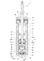
- the shock absorber (Shock Absorber) 1 of the present embodiment is a hydraulic shock absorber in which an oil liquid is used as a working fluid.
- the shock absorber 1 includes a double-cylinder type cylinder 4 having an inner cylinder 2 and an outer cylinder 3.
- the outer cylinder 3 has a larger diameter than the inner cylinder 2 and is arranged coaxially with the inner cylinder 2 so as to cover the inner cylinder 2.
- the space between the inner cylinder 2 and the outer cylinder 3 is a reservoir chamber 5.
- the present invention can be applied not only to the double-cylinder type but also to the single-cylinder type shock absorber.
- the shock absorber 1 has a piston rod 8 and a piston 9.
- the piston 9 is connected to one end of the piston rod 8 in the axial direction. Therefore, the piston 9 moves integrally with the piston rod 8.
- the piston rod 8 is coaxially arranged on the central axis CL of the inner cylinder 2 and the outer cylinder 3. One end side of the piston rod in the axial direction is inserted inside the inner cylinder 2 and the outer cylinder 3 (that is, the cylinder 4), and the other end side in the axial direction extends outward from the inner cylinder 2 and the outer cylinder 3 (that is, the cylinder 4). It has been issued.
- the piston 9 is slidably provided in the inner cylinder 2 of the cylinder 4, and the inside of the inner cylinder 2 is divided into two chambers 11 and 12.
- the piston 9 is slidably provided in the cylinder 4 and one end thereof is connected to the other end side of the piston rod 8 extending to the outside of the cylinder 4.
- the piston rod 8 is provided so as to penetrate only the chamber 11 of the chambers 11 and 12.
- An oil liquid as a working fluid is sealed in the inner cylinder 2 of the cylinder 4. Further, the reservoir chamber 5 between the inner cylinder 2 and the outer cylinder 3 in the cylinder 4 is filled with an oil liquid as a working fluid and a high-pressure (about 20 to 30 atm) gas. That is, the working fluid is sealed in the cylinder 4 having the inner cylinder 2 and the outer cylinder 3.
- the reservoir chamber 5 may be filled with atmospheric pressure air instead of the high-pressure gas.
- the shock absorber 1 has a rod guide 15, a seal member 16, and a friction member 17. Further, the shock absorber 1 has a base valve 18.
- the rod guide 15 is arranged at the end position on the externally protruding side of the piston rod 8 in the cylinder 4.
- the rod guide 15 has a stepped shape, and its large diameter side is fitted inside the outer cylinder 3 and its small diameter side is fitted inside the inner cylinder 2.
- the seal member 16 is an end portion of the cylinder 4 and is arranged outside the rod guide 15 in the axial direction of the cylinder 4.
- the friction member 17 is arranged between the seal member 16 and the rod guide 15.
- the base valve 18 is arranged at an end opposite to the rod guide 15, the seal member 16, and the friction member 17 when viewed along the axial direction in the cylinder 4.
- the rod guide 15, the seal member 16 and the friction member 17 all have an annular shape.
- the piston rod 8 is slidably inserted inside each of the rod guide 15, the seal member 16, and the friction member 17.
- the rod guide 15 supports the piston rod 8 so as to be movable in the axial direction while restricting its radial movement, and guides the movement of the piston rod 8.
- the inner peripheral portion of the seal member 16 is in sliding contact with the outer peripheral portion of the piston rod 8 that moves in the axial direction, and the oil liquid in the inner cylinder 2 and the high-pressure gas and the oil liquid in the reservoir chamber 5 leak to the outside. Prevent it from happening.
- the friction member 17 imparts frictional resistance to the piston rod 8 when its inner peripheral portion is in sliding contact with the outer peripheral portion of the piston rod 8.
- the outer cylinder 3 of the cylinder 4 is composed of a cylindrical body member 21 and a bottom lid member 22.
- the bottom lid member 22 is fitted to one end of the body member 21 in the axial direction.
- the bottom lid member 22 is fixed to the body member 21 so as to be sealed by welding while being fitted to the body member 21.
- the body member 21 has an opening 27 on the side opposite to the bottom lid member 22, and the opening 27 has a locking portion 28.
- the seal member 16 and the rod guide 15 described above are fitted to the opening 27 side of the body member 21.
- the locking portion 28 projects radially inward from the end position of the opening 27 in the body member 21, and sandwiches the sealing member 16 with the rod guide 15.
- the base body 30 of the base valve 18 is arranged inside the bottom lid member 22.
- the base body 30 defines between the chamber 12 in the cylinder 4 and the reservoir chamber 5 described above.
- the base body 30 has a stepped shape in which one side in the axial direction has a smaller diameter than the other side.
- the base body 30 is placed on the bottom lid member 22 on the large diameter side thereof, and is positioned so that its radial position is coaxial with the central axis CL.
- the inner cylinder 2 of the cylinder 4 has a cylindrical shape. One end side of the inner cylinder 2 in the axial direction is supported in a fitted state on the small diameter side of the base body 30 of the base valve 18. Further, the inner cylinder 2 is supported in a state where the other end side in the axial direction is fitted to the small diameter side of the rod guide 15 inside the opening 27 of the outer cylinder 3.
- the base body 30 of the base valve 18 is formed with an insertion hole 29 penetrating in the axial direction at the center in the radial direction.
- Flow passages 31a and 31b that penetrate the base body 30 in the axial direction are formed around the insertion hole 29. These flow passages 31a and 31b allow communication between the chamber 12 in the inner cylinder 2 and the reservoir chamber 5 between the outer cylinder 3 and the inner cylinder 2.
- the disc valve 33a is arranged on the side opposite to the bottom lid member 22, and the disc valve 33b is arranged on the bottom lid member 22 side.
- the disc valve 33a is a check valve and can open and close the outer flow passage 31a.
- the disc valve 33b is a damping valve and can open and close the inner flow passage 31b.
- the disc valves 33a and 33b are attached to the base body 30 by clamping the inner portion in the radial direction by the rivet 35 inserted into the insertion hole 29.
- the disc valve 33b generates a damping force by allowing the flow of oil liquid from the chamber 12 to the reservoir chamber 5 side through the passage hole (not shown) of the disc valve 33a and the flow passage 31b of the base body 30. Regulate the flow of oil in the opposite direction.
- the disc valve 33a allows the oil liquid to flow from the reservoir chamber 5 to the chamber 12 side without resistance through the flow passage 31a of the base body 30, while allowing the oil liquid to flow in the opposite direction. regulate.
- the disc valve 33b causes the pressure in the chamber 12 to rise by a predetermined value from the reservoir chamber 5.
- the flow passage 31b is opened, and a damping force is generated at that time. Therefore, the disc valve 33b is a damping valve on the contraction side.
- the disc valve 33a causes the pressure in the chamber 12 to drop by a predetermined value from the reservoir chamber 5.
- the flow passage 31a is opened, but at that time, the oil liquid is flowed from the reservoir chamber 5 into the chamber 12 without substantially generating a damping force. Therefore, the disc valve 33a is a suction valve.
- the disc valve 33a as a check valve may positively generate a damping force on the extension side. Further, these disc valves 33a and 33b may be abolished and an orifice may be adopted instead.
- the piston rod 8 has a mounting shaft portion 40 and a spindle portion 41.
- the mounting shaft portion 40 is a portion to which the piston 9 is mounted, and is formed on the insertion tip side of the piston rod 8 into the cylinder 4.
- the spindle portion 41 is a portion other than the mounting shaft portion 40 of the piston rod 8, and has a larger diameter than the mounting shaft portion 40.
- the piston rod 8 is slidably inserted inside each of the rod guide 15, the seal member 16, and the friction member 17 in the spindle portion 41.
- a retainer 42 is fixed to the spindle portion 41 so as to spread outward in the radial direction on the mounting shaft portion 40 side of the insertion portion into the rod guide 15.
- a shock absorber 43 made of an annular elastic material is provided with the main shaft portion 41 inserted inside.
- the piston 9 has a plurality of passages 50a (only one place is shown in the cross-sectional view in FIG. 2) and a plurality of passages 50a (only one place is shown in the cross-sectional view in FIG. 2). ) Is provided with a passage 50b. These passages 50a and 50b allow the chamber 11 and the chamber 12 to communicate with each other.
- the first damping force generation mechanism 51b which will be described later, is provided for the passage 50b to block the passage 50b. Therefore, the movement of the piston 9 causes the oil liquid to flow out from the chamber 11 which is one of the chambers 11 and 12 toward the chamber 12 which is the other through the passage 50a. In other words, in the passage 50a of the piston 9, when the piston 9 moves in one direction, the working fluid flows out from the chamber 11 which is one of the chamber 11 and the chamber 12 in the cylinder 4.
- one side in the axial direction (chamber 11 side) of the piston 9 is radially outward, and the other side in the axial direction (chamber 12 side) is radially inward.
- a first damping force generation mechanism 51a for generating a damping force is provided in these passages 50a.
- the first damping force generation mechanism 51a is arranged on the chamber 12 side in the axial direction of the piston 9.
- the passage 50a constitutes a passage on the extension side through which the oil liquid flows out from the chamber 11 during the extension stroke.
- the first damping force generation mechanism 51a provided for the passage 50a is an extension side damping force generation mechanism that suppresses the flow of the oil liquid in the extension side passage 50a to generate a damping force.
- the other side in the axial direction (chamber 12 side) of the piston 9 is radially outward, and the axial one side (chamber 11 side) is radially inward.
- a first damping force generation mechanism 51b for generating a damping force is provided in these passages 50b.
- the first damping force generation mechanism 51b is arranged on the chamber 11 side in the axial direction of the piston 9.
- the passage 50b constitutes a passage on the contraction side through which the oil liquid flows out from the chamber 12 during the contraction stroke described above.
- the first damping force generating mechanism 51b provided for the passage 50b is a damping force generating mechanism on the shrinking side that suppresses the flow of the oil liquid in the passage 50b on the shrinking side to generate a damping force.
- the piston rod 8 is formed with a hole portion 55 that penetrates the mounting shaft portion 40 in the radial direction at the position of the mounting shaft portion 40. Further, in the piston rod 8, a hole portion 56 having a diameter larger than that of the hole portion 55 is formed along the axial direction from the position of the hole portion 55 to the tip portion on the opposite side of the main shaft portion 41. These holes 55 and 56 communicate with each other to form an in-rod passage 57 provided in the piston rod 8.
- a damping force variable mechanism 58 is attached to the piston rod 8 on the side opposite to the main shaft portion 41 with respect to the piston 9 of the mounting shaft portion 40.
- the damping force variable mechanism 58 is attached so as to cover the hole 56 of the in-rod passage 57, and the inside thereof communicates with the in-rod passage 57.
- the above-mentioned shock absorber 1 is provided for each wheel of the vehicle. At that time, for example, one side of the shock absorber 1 is supported by the vehicle body, and the other side is fixed to the wheel side. Specifically, it is connected to the vehicle body side by the piston rod 8, and the outer cylinder 3 side of the cylinder 4 is connected to the wheel side. Contrary to the above, the other side of the shock absorber 1 may be supported by the vehicle body and one side of the shock absorber 1 may be fixed to the wheel side.
- the piston 9 has a substantially disk-shaped piston main body 61 and a sliding contact member 62 mounted on the outer peripheral surface of the piston main body 61.
- the piston 9 is in sliding contact with the inner peripheral surface of the inner cylinder 2 of the cylinder 4 in the sliding contact member 62.
- the piston body 61 is formed with an insertion hole 63 in the center in the radial direction so as to penetrate in the axial direction. Then, the mounting shaft portion 40 of the piston rod 8 is inserted into the insertion hole 63.
- the above-mentioned passages 50a and 50b are formed in the piston main body 61 so as to surround the insertion hole 63.
- a valve seat 71a is formed at the end of the piston body 61 on the chamber 12 side in the axial direction.
- the valve seat 71a is formed in an annular shape on the outside of the opening position at one end of the passage 50a on the extension side.
- a valve seat 71b is formed at the end of the piston body 61 on the chamber 11 side in the axial direction.
- the valve seat 71b is formed in an annular shape on the outside of the opening position at one end of the passage 50b on the contraction side.
- the valve seat 71a constitutes a first damping force generation mechanism 51a.
- the valve seat 71b constitutes a first damping force generation mechanism 51b.
- the side opposite to the insertion hole 63 of the valve seat 71a has a lower axial height than the valve seat 71a, and the other end of the passage 50b on the contraction side is opened in this portion.
- the side of the valve seat 71b opposite to the insertion hole 63 has a lower axial height than the valve seat 71b, and the other end of the extension-side passage 50a opens in this portion. doing.
- the first damping force generation mechanism 51a is composed of the valve seat 71a described above and an annular disc valve 75a that can be seated on the valve seat 71a.
- the disc valve 75a is configured by superimposing a plurality of annular single discs.
- An intervening disc 76a is arranged on the piston body 61 side of the disc valve 75a.
- An annular valve regulating member 77a is arranged on the side of the disc valve 75a opposite to the piston body 61.
- the intervening disc 76a is configured by superimposing a plurality of annular single discs.
- the first damping force generating mechanism 51a has a fixed orifice 78a between the valve seat 71a and the disc valve 75a so that the passage 50a communicates with the chamber 12 even when they are in contact with each other.
- the fixed orifice 78a is formed by a groove formed in the valve seat 71a or an opening formed in the disc valve 75a.
- the disc valve 75a opens the passage 50a by leaving the valve seat 71a.
- the valve regulating member 77a regulates the deformation of the disc valve 75a beyond the specified direction in the opening direction.
- the first damping force generation mechanism 51a is provided in the passage 50a, and suppresses the flow of the oil liquid generated in the passage 50a due to the sliding of the piston 9 toward the chamber 11 side to generate the damping force.
- the first damping force generation mechanism 51a has a disc-shaped disc valve 75a, and opens and closes the passage 50a of the piston 9 to generate a damping force.
- the first damping force generation mechanism 51b is composed of the valve seat 71b described above and an annular disc valve 75b that can be seated on the valve seat 71b.
- the disc valve 75b is also configured by superimposing a plurality of annular single discs.
- An intervening disc 76b is arranged on the piston body 61 side of the disc valve 75b.
- An annular valve regulating member 77b is arranged on the side of the disc valve 75b opposite to the piston body 61. The valve regulating member 77b is in contact with the end surface of the main shaft portion 41 of the piston rod 8 on the mounting shaft portion 40 side.
- the first damping force generation mechanism 51b has a fixed orifice 78b between the valve seat 71b and the disc valve 75b that allows the passage 50b to communicate with the chamber 11 even when they are in contact with each other.
- the fixed orifice 78b is formed by a groove formed in the valve seat 71b or an opening formed in the disc valve 75b.
- the disc valve 75b opens the passage 50b by leaving the valve seat 71b.
- the valve regulating member 77b regulates the deformation of the disc valve 75b in the opening direction or more.
- the first damping force generation mechanism 51b is provided in the passage 50b, and suppresses the flow of the oil liquid generated in the passage 50b due to the sliding of the piston 9 toward the chamber 12, to generate the damping force.
- the first damping force generation mechanism 51b has a disc-shaped disc valve 75b, and opens and closes the passage 50b of the piston 9 to generate a damping force.
- the single disc that is closest to the piston body 61 side has a notch on the inner peripheral side, and this notched portion constitutes the passage 70 in the disc.
- An axial passage 200 extending in the axial direction is formed between the mounting shaft portion 40 of the piston rod 8 and the insertion hole 63 of the piston body 61.
- the in-disk passage 70 always communicates between the axial passage 200 and the passage 50a.
- the hole portion 55 constituting the in-rod passage 57 of the piston rod 8 always communicates with the axial passage 200.
- the piston body 61 is composed of two parts, a piston body 201 on the chamber 12 side and a piston body 202 on the chamber 11 side.
- the piston body 201 and the piston body 202 are integrated with the sliding contact member 62 by an endless band shape in a state where they are positioned in the circumferential direction and the radial direction and cannot rotate relative to each other.
- the piston bodies 201 and 202 and the sliding contact member 62 are integrated to form the piston 9.
- the annular valve seat 71a described above is formed on the piston body 201 on the side opposite to the piston body 202.
- the annular valve seat 71b described above is formed on the piston body 202 on the side opposite to the piston body 201.
- a through hole 211 forming a part of the above-mentioned insertion hole 63 is formed so as to penetrate in the axial direction at the center in the radial direction.
- a through hole 212 forming a part of the insertion hole 63 is formed so as to penetrate in the axial direction at the center in the radial direction.
- the through hole 212 has a smaller diameter than the through hole 211.
- the mounting shaft portion 40 of the piston rod 8 fits into the through hole 212.
- the axial passage 200 is formed between the mounting shaft portion 40 of the piston rod 8 and the through hole 211 of the piston body 201.
- the in-rod passage 57 provided in the piston rod 8 is always in communication with the in-disk passage 70 via the axial passage 200.
- the in-disk passage 70, the axial passage 200, and the in-rod passage 57 are always in communication with the chamber 11 via the passage 50a.
- a male screw 80 is formed on the mounting shaft portion 40 of the piston rod 8 on the tip side opposite to the spindle portion 41 from the hole portion 55.
- the male screw 80 is formed on the end side of the mounting shaft portion 40 of the piston rod 8 that protrudes from the piston 9.
- the damping force variable mechanism 58 described above is screwed into the male screw 80.
- the damping force variable mechanism 58 is a frequency-sensitive unit that generates a damping force and makes the damping force variable without being externally controlled by the frequency (vibration state) at that time.
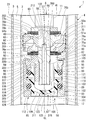
- the damping force variable mechanism 58 has the valve regulating member 77a, the disc valve 75a, the interposing disc 76a, the piston 9, the interposing disc 76b, the disc valve 75b, and the valve regulating member 77b in a state of being screwed into the male screw 80. , It is sandwiched between the end face of the spindle portion 41 of the piston rod 8.
- the damping force variable mechanism 58 includes a housing 85 composed of a nut member 82 and a tubular case member 83 (case portion) separate from the nut member 82, a free piston 87, and an O-ring 88 (elastic member) which is a rubber member. ) And an O-ring 89 (elastic member) which is a rubber member.
- the nut member 82 is formed with a female screw 81 screwed into the male screw 80 of the piston rod 8.
- the case member 83 has a substantially cylindrical shape, and one end opening side thereof is joined to the nut member 82.
- the free piston 87 and the O-rings 88 and 89 are housed in the case member 83.
- the free piston 87 is provided in the housing 85 so as to be movable in the axial direction.
- the O-ring 88 is provided between the free piston 87 and the nut member 82.
- the O-ring 88 is an elastic body on the contraction side that is compressed and deformed when the free piston 87 moves toward the nut member 82 in the axial direction with respect to the housing 85.
- the O-ring 89 is provided between the free piston 87 and the case member 83.
- the O-ring 89 is an elastic body on the extension side that is compressed and deformed when the free piston 87 moves to the side opposite to the above with respect to the housing 85.
- FIG. 2 illustrates the O-rings 88 and 89 in their natural state for convenience.
- the O-ring 89 also functions as a seal, it is desirable that the O-ring 89 be arranged so that its cross section is always deformed into a non-circular shape in the attached state.
- the O-ring 88 described above is a resistance element that compresses and deforms when the free piston 87 moves in one direction and generates a resistance force against the displacement of the free piston 87.
- the O-ring 89 is a resistance element that is compressed and deformed when the free piston 87 moves in the other direction and generates a resistance force against the displacement of the free piston 87.
- the nut member 82 is made of metal such as iron, and is mainly formed by cutting.
- the nut member 82 has a nut portion 91, a substrate portion 92, an outer cylinder portion 93, and an annular portion 94.
- the nut portion 91 has a substantially cylindrical shape, and the female screw 81 described above is formed on the inner peripheral portion thereof.
- the nut portion 91 surrounds one end of the inside of the cylinder 4 of the piston rod 8 and is formed with a female screw 81 screwed into the male screw 80.
- the substrate portion 92 has a perforated disk shape extending radially outward from one end portion in the axial direction of the nut portion 91.
- the outer cylinder portion 93 extends from the outer peripheral side of the substrate portion 92 to the same side as the nut portion 91 in the axial direction thereof.
- the annular portion 94 projects radially outward from the same side as the axial substrate portion 92 of the outer cylinder portion 93.
- the annular portion 94 has a tapered surface portion 95 connected to the outer cylinder portion 93 with a gradually smaller diameter at the end portion on the outer cylinder portion 93 side in the axial direction.
- the nut portion 91 and the female screw 81 on the inner peripheral side thereof have an axially protruding length from the substrate portion 92 longer than that of the outer cylinder portion 93.
- the inner peripheral surface of the outer cylinder portion 93 has a cylindrical surface portion 96 and an inclined surface portion 97 in this order from the substrate portion 92 side.
- the cylindrical surface portion 96 has a constant diameter.
- the inclined surface portion 97 is connected to the cylindrical surface portion 96, and forms an annular shape having a larger diameter as the distance from the cylindrical surface portion 96 in the axial direction increases.
- the inclined surface portion 97 has a substantially arcuate cross section on the surface including the central axis CL of the nut member 82.
- the case member 83 is made of a metal such as iron and is formed mainly by cutting, and has a substantially cylindrical shape.
- the case member 83 includes a cylindrical main body 301, a cylindrical tubular portion 302 extending axially outward from one end in the axial direction of the main body 301, and an axial main body 301 of the tubular portion 302.
- It has an inner annular protrusion 304 protruding from the surface.
- the tubular portion 302 has the same outer diameter as the main portion 301 and has a larger inner diameter. Therefore, the tubular portion 302 has a thinner cylindrical shape than the main body portion 301.
- a small-diameter cylindrical surface portion 101 On the inner peripheral surface of the case member 83, a small-diameter cylindrical surface portion 101, an inclined surface portion 102, a medium-diameter cylindrical surface portion 103, a tapered surface portion 105, and a large-diameter cylindrical surface portion 104 are formed in order from one side in the axial direction.
- the small-diameter cylindrical surface portion 101 has a constant diameter.
- the inclined surface portion 102 is connected to the small-diameter cylindrical surface portion 101, and has an annular shape with a larger diameter as the distance from the small-diameter cylindrical surface portion 101 increases.
- the inclined surface portion 102 has a substantially arcuate cross section on the surface including the central axis CL of the case member 83.
- the small-diameter cylindrical surface portion 101 and the inclined surface portion 102 are formed on the inner annular projection 304.
- the medium-diameter cylindrical surface portion 103 is connected to the inclined surface portion 102 and has a constant diameter larger than that of the small-diameter cylindrical surface portion 101.
- the tapered surface portion 105 is connected to the medium-diameter cylindrical surface portion 103, and has a tapered shape in which the diameter increases as the distance from the medium-diameter cylindrical surface portion 103 increases.
- the medium-diameter cylindrical surface portion 103 and the tapered surface portion 105 are formed on the main body portion 301.
- the large-diameter cylindrical surface portion 104 is connected to the tapered surface portion 105 and has a constant diameter larger than that of the medium-diameter cylindrical surface portion 103.
- the large-diameter cylindrical surface portion 104 is formed on the tubular portion 302.
- the case member 83 is cylindrical, and it is desirable that the inner peripheral surface thereof has a circular cross section, but the outer peripheral surface may have a non-circular cross section such as a polygon.
- the nut member 82 is inserted inside the locking portion 303 in a state where the locking portion 303 has the same cylindrical shape as the tubular portion 302. Then, in a state where the tapered surface portion 95 of the annular portion 94 is in contact with the tapered surface portion 105, the locking portion 303 on the side opposite to the inner annular projection 304 in the axial direction from the annular portion 94 of the case member 83 is radially oriented. By bending inward, the case member 83 and the nut member 82 are integrated into a housing 85.
- the outer cylinder portion 93 of the nut member 82 constitutes, in the housing 85, an annular small diameter portion that protrudes radially inward from the medium diameter cylindrical surface portion 103, and the inclined surface portion 97 is formed in this portion.
- the inner annular protrusion 304 of the case member 83 constitutes an annular small diameter portion that protrudes radially inward from the medium diameter cylindrical surface portion 103 in the housing 85, and the inclined surface portion 102 is formed in this portion.
- the inclined surface portion 97 and the inclined surface portion 102 are arranged so as to face each other in the axial direction.
- the outer diameter of the damping force variable mechanism 58 that is, the outer diameter of the housing 85 is set to be smaller than the inner diameter of the inner cylinder 2 so as not to cause flow path resistance.
- the free piston 87 is an integrally molded product formed of, for example, a synthetic resin material.
- the free piston 87 has a substantially cylindrical piston cylinder portion 108 and a curved plate-shaped piston bottom portion 109.
- the piston bottom portion 109 is formed so as to close one end side of the piston cylinder portion 108 in the axial direction.
- An opening 220 is formed on the side of the piston cylinder portion 108 opposite to the piston bottom portion 109 in the axial direction.
- the free piston 87 has a bottomed tubular shape having a piston cylinder portion 108 and a piston bottom portion 109.
- the free piston 87 is made of only a synthetic resin material.
- the piston cylinder portion 108 is formed with an outer annular protrusion 110 that protrudes outward in the radial direction at an intermediate position in the axial direction.
- the outer annular protrusion 110 has a larger diameter than the cylinder main body 221 excluding the outer annular protrusion 110 of the piston cylinder 108, and forms an annular shape that protrudes outward in the radial direction from the cylinder main body 221. There is.
- the tapered surface portion 112 On the outer peripheral surface of the piston cylinder portion 108, the tapered surface portion 112, the small diameter cylindrical surface portion 113, the inclined surface portion 114, the large diameter cylindrical surface portion 115, the inclined surface portion 116, and the small diameter cylindrical surface portion 117 are arranged in order from the side opposite to the opening 220 in the axial direction. And the tapered surface portion 118 is formed.
- the tapered surface portion 112, the small-diameter cylindrical surface portion 113, the small-diameter cylindrical surface portion 117, and the tapered surface portion 118 are formed on the tubular portion main body portion 221.
- the inclined surface portion 114, the large-diameter cylindrical surface portion 115, and the inclined surface portion 116 are formed on the outer annular projecting portion 110.
- the tapered surface portion 112 has a tapered shape whose diameter becomes smaller toward the side opposite to the small diameter cylindrical surface portion 113 along the axial direction.
- the small-diameter cylindrical surface portion 113 is connected to the large-diameter side of the tapered surface portion 112 and has a constant diameter.
- the inclined surface portion 114 is connected to the small-diameter cylindrical surface portion 113, and forms an annular shape having a larger diameter as the distance from the small-diameter cylindrical surface portion 113 in the axial direction increases.
- the large-diameter cylindrical surface portion 115 is connected to the large-diameter side of the inclined surface portion 114, and has a constant diameter larger than that of the small-diameter cylindrical surface portion 113.
- the inclined surface portion 114 has a substantially arcuate cross section on the surface including the central axis CL of the free piston 87.
- the inclined surface portion 116 is connected to the large-diameter cylindrical surface portion 115, and forms an annular shape whose diameter becomes smaller as the distance from the large-diameter cylindrical surface portion 115 increases.
- a small-diameter cylindrical surface portion 117 is connected to the small-diameter side of the inclined surface portion 116.
- the small-diameter cylindrical surface portion 117 has a constant diameter having the same diameter as the small-diameter cylindrical surface portion 113.
- the tapered surface portion 118 is connected to the small-diameter cylindrical surface portion 117, and has a tapered shape having a smaller diameter toward the side opposite to the small-diameter cylindrical surface portion 117 along the axial direction.
- the inclined surface portion 116 has a substantially arcuate cross section on the surface including the central axis CL of the free piston 87.
- the piston cylinder portion 108 has a mirror-symmetrical shape with respect to a plane passing through the central position in the axial direction thereof.
- the free piston 87 is formed with a plurality of passage holes 119 at intervals in the circumferential direction of the free piston 87.
- the passage hole 119 is formed at the central position in the axial direction of the outer annular protrusion 110.
- the passage hole 119 radially penetrates the position of the outer annular protrusion 110 in the axial direction of the piston cylinder 108.
- the passage hole 119 is slightly narrowed so that the diameter becomes smaller toward the inside in the radial direction of the piston cylinder portion 108.
- the passage holes 119 are formed at two locations different by 180 degrees in the circumferential direction of the free piston 87.
- the piston bottom portion 109 is curved in a substantially spherical shape so as to be separated from the opening 220 in the axial direction toward the center side in the radial direction.
- the free piston 87 is arranged in the housing 85 so that the piston bottom 109 is arranged on the side opposite to the nut member 82 in the axial direction. At that time, the nut portion 91 of the nut member 82 is inserted into the piston cylinder portion 108 from the opening 220 side. In the state where the free piston 87 is arranged in the housing 85, the large-diameter cylindrical surface portion 115 slides on the medium-diameter cylindrical surface portion 103 of the case member 83 in the axial direction.
- the inclined surface portion 102 of the case member 83 and the inclined surface portion 114 of the free piston 87 overlap the radial positions and face each other in the axial direction.
- the inclined surface portion 97 of the outer cylinder portion 93 of the nut member 82 and the inclined surface portion 116 of the free piston 87 overlap the radial positions and face each other in the axial direction.
- An O-ring 89 (natural state is shown in FIG. 2) is arranged between the small-diameter cylindrical surface portion 113 and the inclined surface portion 114 of the free piston 87 and the inclined surface portion 102 and the medium-diameter cylindrical surface portion 103 of the case member 83. ing. In other words, the O-ring 89 is arranged between the outer annular protrusion 110 of the free piston 87 and the inner annular protrusion 304 of the housing 85. When the O-ring 89 is in a natural state, the cross section of the surface including the central axis CL has a circular shape.
- the O-ring 89 has an inner diameter smaller than that of the small-diameter cylindrical surface portion 113 of the free piston 87 and an outer diameter larger than that of the medium-diameter cylindrical surface portion 103 of the case member 83. That is, the O-ring 89 is fitted to both the free piston 87 and the housing 85 with these radial tightening allowances.
- an O-ring 88 (natural state is shown in FIG. 2) is arranged between the medium-diameter cylindrical surface portion 103 and the inclined surface portion 97 of the housing 85 and the inclined surface portion 116 and the small-diameter cylindrical surface portion 117 of the free piston 87.
- the O-ring 88 is arranged between the outer annular protrusion 110 of the free piston 87 and the outer cylinder portion 93 of the housing 85.
- the O-ring 88 has an inner diameter smaller than that of the small-diameter cylindrical surface portion 117 of the free piston 87 and an outer diameter larger than that of the medium-diameter cylindrical surface portion 103 of the housing 85. That is, the O-ring 88 is also fitted to both the free piston 87 and the housing 85 with these radial tightening allowances.
- Both O-rings 88 and 89 are common parts with the same size.
- the O-rings 88 and 89 urge the free piston 87 to hold the free piston 87 in a predetermined axially neutral position with respect to the housing 85 within the housing 85.
- the O-rings 88 and 89 allow the free piston 87 to move on both sides in the axial direction with respect to the housing 85 by elastically deforming.
- the space between the housing 85, the free piston 87, and the O-rings 88 and 89 is a passage 121 in the housing.
- the in-disk passage 70 is an orifice.
- the inside of the in-housing passage 121 formed in the housing 85 is at least a part of the rod-side passage 122.
- the free piston 87 and the O-rings 88 and 89 provided inside the case member 83 of the housing 85 provide a second damping force generation mechanism 311 provided in the rod-side passage 122 to generate a damping force by the movement of the piston 9. It is configured.
- the passage 121 in the housing is a passage portion 123 on the rod chamber side that always communicates with the chamber 11 on the piston rod 8 side and a bottom chamber side that always communicates with the chamber 12 on the bottom side by the O-ring 89, the free piston 87, and the housing 85. It is defined as a passage portion 124.
- the rod chamber side passage portion 123 is composed of a chamber 125, a passage hole 119, and a chamber 126.
- the chamber 125 is surrounded by a nut member 82, a free piston 87, and an O-ring 88, and an in-rod passage 57 opens.
- the passage hole 119 is formed in the free piston 87, and one end thereof opens in the chamber 125.
- the chamber 126 is surrounded by a case member 83, an O-ring 88, an O-ring 89, and a free piston 87, and the other end of the passage hole 119 is opened.
- the bottom chamber side passage portion 124 is composed of a portion surrounded by the inner annular projection 304 side of the case member 83, the O-ring 89, and the free piston 87.
- the oil liquid in the chamber 11 having a high pressure among the chambers 11 and 12 becomes the passage 50a in the rod side passage 122, the in-disk passage 70, and the axial passage 200. It flows to the passage 57 in the rod and the passage 123 on the rod chamber side. Then, the free piston 87 moves to the side opposite to the nut member 82 in the axial direction with respect to the housing 85 while discharging the oil liquid of the bottom chamber side passage portion 124 to the chamber 12.
- one O-ring 89 provided between the free piston 87 and the housing 85 is an inclined surface portion 114 of the outer annular protrusion 110 of the free piston 87 and an inclined surface portion 102 of the inner annular protrusion 304 of the housing 85. It comes into contact with and is sandwiched between them and elastically deformed. That is, one of the O-rings 89 generates an elastic force against the movement of the free piston 87 to one side in the extension stroke.
- the oil liquid in the chamber 12 which has a high pressure among the chambers 11 and 12, presses the free piston 87.
- the free piston 87 moves to the nut member 82 side in the axial direction with respect to the housing 85 while injecting the oil liquid into the bottom chamber side passage portion 124.
- the other O-ring 88 provided between the free piston 87 and the housing 85 is an inclined surface portion 116 of the outer annular protrusion 110 of the free piston 87 and an inclined surface portion 97 of the outer cylinder portion 93 of the housing 85. It comes into contact with and is sandwiched between them and elastically deformed. That is, the other O-ring 88 generates an elastic force against the movement of the free piston 87 to the other in the contraction stroke.
- the chamber 11 side of the chambers 11 and 12 which becomes high pressure in the extension stroke is recessed in a curved shape, and the chamber 12 side of the chambers 11 and 12 which becomes high pressure in the contraction stroke protrudes in a curved surface. ..
- the O-ring 89, the free piston 87, and the housing 85 define the rod chamber side passage portion 123 and the bottom chamber side passage portion 124. Therefore, the free piston 87 and the O-ring 89 pass through the rod-side passage 122 on the upstream side passage 50a, the in-disk passage 70, and the axial passage 200 when the piston 9 moves in one direction in the extension stroke.
- the in-rod passage 57 and the rod chamber side passage portion 123, and the downstream side bottom chamber side passage portion 124 are defined.
- the free piston 87 and the O-ring 89 have the rod-side passage 122, the bottom chamber-side passage portion 124 on the upstream side of the oil liquid flow when the piston 9 moves in the other direction in the contraction stroke, and the rod chamber side on the downstream side. It is defined as a passage portion 123, an in-rod passage 57, an axial passage 200, an in-disk passage 70, and a passage 50a.
- the free piston 87 and the O-rings 88 and 89 provided inside the housing 85 form a second damping force generation mechanism 311 provided in the rod side passage 122 to generate a damping force by the movement of the piston 9. That is, the second damping force generation mechanism 311 controls the flow of the oil liquid in the rod side passage 122 according to the position of the free piston 87 to generate the damping force. Therefore, the case member 83 of the housing 85 houses the free piston 87 and the O-rings 88 and 89, which are internal parts of the second damping force generation mechanism 311, inside the case member 83.
- the oil liquid flows from the chamber 11 to the chamber 12 via the passage 50a.
- the oil liquid introduced from the chamber 11 into the passage 50a is basically always opened between the valve seat 71a and the disc valve 75a abutting on the valve seat 71a. It flows into the chamber 12 through the fixed orifice 78a of the above, and at that time, the damping force of the orifice characteristic (the damping force is substantially proportional to the square of the piston speed) is generated.
- the oil liquid introduced from the chamber 11 into the passage 50a basically passes between the disc valve 75a and the valve seat 71a while opening the disc valve 75a. Flow to 12. Therefore, a damping force having a valve characteristic (damping force is substantially proportional to the piston speed) is generated.
- the oil liquid flows from the chamber 12 to the chamber 11 via the passage 50b.
- the oil liquid introduced from the chamber 12 into the passage 50b basically has a constant opening formed between the valve seat 71b and the disc valve 75b abutting on the valve seat 71b. It flows into the chamber 11 through the fixed orifice 78b. Then, at that time, a damping force having an orifice characteristic (damping force is substantially proportional to the square of the piston speed) is generated.
- the oil liquid introduced from the chamber 12 into the passage 50b basically passes between the disc valve 75b and the valve seat 71b while opening the disc valve 75b. Flow to 11. Therefore, a damping force having a valve characteristic (damping force is substantially proportional to the piston speed) is generated.
- the piston speed when the piston speed is slow, that is, the region where the frequency in the very low speed region (for example, 0.05 m / s) is relatively high (for example, 7 Hz or more) is vibration generated from the fine surface unevenness of the road surface, for example. In such a situation, it is preferable to reduce the damping force. Also, even when the piston speed is slow, contrary to the above, the region where the frequency is relatively low (for example, 2 Hz or less) is vibration such as wobbling due to the roll of the vehicle body, and in such a situation, the damping force. It is preferable to raise it.
- the above-mentioned damping force variable mechanism 58 makes the damping force variable according to the frequency even when the piston speed is similarly slow. That is, when the piston speed is slow and the frequency of the reciprocating motion of the piston 9 becomes high, the pressure in the chamber 11 becomes high in the extension stroke. Then, among the rod-side passages 122, the rod chamber-side passage portion 123 of the housing inner passage 121 of the damping force variable mechanism 58 passes through the passage 50a, the in-disk passage 70, the axial passage 200, and the in-rod passage 57.
- the free piston 87 moves to the chamber 12 side in the axial direction with respect to the housing 85 against the urging force of the O-ring 89 on the chamber 12 side in the axial direction.
- the oil liquid is introduced from the chamber 11 into the passage 121 in the housing.
- the flow rate of the oil liquid introduced from the chamber 11 into the passage 50a, passing through the first damping force generating mechanism 51a, and flowing into the chamber 12 is reduced.
- the damping force is reduced.
- the amount of oil liquid flowing into the damping force variable mechanism 58 is controlled by the throttle effect of the passage 70 in the disk.
- the pressure in the chamber 12 becomes high, so that the damping force variable mechanism is provided through the rod-side passage 57 of the piston rod 8, the axial passage 200, the disc passage 70, and the passage 50a in the rod-side passage 122.
- the free piston 87 which had previously moved to the chamber 12 side in the axial direction while discharging the oil liquid from the passage portion 123 on the rod chamber side of the passage 121 in the housing of 58 to the chamber 11, is located on the chamber 11 side in the axial direction. It moves toward the chamber 11 in the axial direction with respect to the housing 85 against the urging force of the ring 88. By moving the free piston 87 toward the chamber 11 in the axial direction in this way, the volume of the chamber 12 is expanded.
- the frequency of movement of the free piston 87 also follows and increases.
- the oil liquid flows from the chamber 11 to the rod chamber side passage portion 123 of the passage 121 in the housing at each expansion stroke described above, and the volume of the chamber 12 expands by the amount of movement of the free piston 87 at each contraction stroke. Will be done. Therefore, the damping force is maintained in a lowered state.
- the frequency of movement of the free piston 87 also follows and becomes low. Therefore, at the initial stage of the extension stroke, the oil liquid flows from the chamber 11 to the rod chamber side passage portion 123 of the passage inside the housing 121. However, after that, the free piston 87 compresses the O-ring 89 and stops on the chamber 12 side in the axial direction with respect to the housing 85, and the oil liquid does not flow from the chamber 11 to the rod chamber side passage portion 123 of the housing inner passage 121. .. Therefore, the flow rate of the oil liquid introduced from the chamber 11 into the passage 50a, passing through the first damping force generating mechanism 51a, and flowing to the chamber 12 is not reduced, and the damping force is increased.
- the volume of the chamber 12 will be expanded by the amount of movement of the free piston 87 with respect to the housing 85 at the initial stage.
- the free piston 87 compresses the O-ring 88 and stops on the chamber 11 side in the axial direction with respect to the housing 85, so that the volume of the chamber 12 is not affected. Therefore, the flow rate of the oil liquid introduced from the chamber 12 into the passage 50b, passing through the first damping force generating mechanism 51b, and flowing to the chamber 11 is not reduced, and the damping force is increased.
- the manufacturing method of the present embodiment includes a method of assembling the piston 9 and the damping force variable mechanism 58 to the piston rod 8.
- the disc valve 75a and the valve regulating member 77a are assembled in this order by fitting the mounting shaft portion 40 of the piston rod 8 inside each of them.
- the female screw 81 of the nut member 82 is screwed into the male screw 80 of the mounting shaft portion 40 protruding from the valve regulating member 77a on the side opposite to the piston 9.
- the nut member 82 is oriented so that the substrate portion 92 is located closer to the piston 9 than the nut portion 91 and the outer cylinder portion 93.
- the valve regulating member 77b and the disc valve 75b are formed at the substrate portion 92 of the nut member 82 and the end portion of the main shaft portion 41 of the piston rod 8 on the mounting shaft portion 40 side.
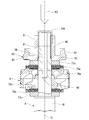
- This step is the first fastening step in which the nut member 82 of the housing 85 is screwed and fastened to the male screw 80 of the piston rod 8.
- the step of performing this rotation regulation processing is the second fastening step.
- a rotation restricting portion 315 is formed in which at least one of the male screw 80 of the piston rod 8 and the female screw 81 of the nut portion 91 of the nut member 82 is plastically deformed.
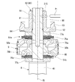
- the nut portion 91 and the mounting shaft are pressed by the punch P1 from the outer periphery of the nut portion 91 of the nut member 82 via the nut portion 91.
- the portion 40 is crimped inward in the radial direction to plastically deform the female screw 81 of the nut portion 91 and the male screw 80 of the piston rod 8.
- the rotation restricting portion 315 formed by plastically deforming both of the male screw 80 of the piston rod 8 and the female screw 81 of the nut member 82 is formed.
- the rotation regulating portion 315 regulates the rotation of the nut member 82 with respect to the piston rod 8.
- the rotation control unit 315 may be configured such that only the female screw 81 of the nut member 82 of the male screw 80 of the piston rod 8 and the female screw 81 of the nut member 82 is plastically deformed.
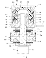
- the O-rings 88 and 89 and the free piston 87 are previously placed inside the case member 83 in which the locking portion 303 has a tubular shape by the frictional force of the O-rings 88 and 89. Assemble it. That is, first, the O-ring 89 is inserted into the case member 83. Next, the free piston 87 is fitted inside the case member 83 and the O-ring 89. Next, the O-ring 88 is inserted between the case member 83 and the free piston 87.
- the nut member 82 is covered with the cylindrical locking portion 303 and the tubular portion 302 of the case member 83 in which the O-rings 88 and 89 and the free piston 87 are pre-assembled as described above.
- the case member 83 abuts the tapered surface portion 105 of the main body portion 301 on the tapered surface portion 95 of the nut member 82 and stops.
- the tubular portion 302 overlaps the annular portion 94 of the nut member 82 with the axial position and covers the annular portion 94 on the outer side in the radial direction.
- the cylindrical locking portion 303 projects toward the piston 9 in the axial direction from the annular portion 94.
- a case member mounting step is performed in which the cylindrical locking portion 303 is plastically deformed inward in the radial direction to form a flat plate as shown in FIG.
- the case member 83 sandwiches the annular portion 94 of the nut member 82 from both sides in the axial direction between the main body portion 301 and the locking portion 303.
- the case member 83 is integrated with the nut member 82 to form the housing 85.
- the O-rings 88 and 89 and the free piston 87 constituting the second damping force generation mechanism 311 are housed in the housing 85.
- Patent Document 1 describes a shock absorber for screwing a housing for accommodating internal unit parts into a portion of a piston rod protruding from a piston. Further, Patent Document 2 describes a shock absorber that regulates loosening by screwing a nut into a portion of a piston rod protruding from a piston and crimping the nut. By the way, there is a demand for suppressing an increase in the number of parts in a shock absorber.
- the manufacturing method of the present embodiment includes a first fastening step in which the nut portion 91 of the housing 85 is screwed and fastened to the male screw 80 of the piston rod 8, and the male screw 80 of the piston rod 8 and the nut portion 91 of the housing 85. It includes a second fastening step of plastically deforming at least one of them to perform a rotation restricting process for restricting the rotation of the housing 85 with respect to the piston rod 8.
- the shock absorber 1 of the present embodiment has a rotation restricting portion 315 formed by plastically deforming at least one of the male screw 80 of the piston rod 8 and the nut portion 91 of the housing 85. ..
- a dedicated member for detenting the housing 85 (for example, a nut for forming a double nut structure) is not required, so that an increase in the number of parts can be suppressed and the manufacturing cost can be reduced. The increase can be suppressed.
- the basic length of the shock absorber 1 can be shortened. Further, since it is not necessary to apply a coating for preventing loosening, the rotational torque can be stabilized and the occurrence of contamination can be suppressed.
- the housing 85 is composed of a nut member 82 and a tubular case member 83.
- the piston rod 8 is pressed from the outer periphery of the nut member 82 to plastically deform the male screw 80 of the piston rod 8.
- the rotation control unit 315 is configured by plastically deforming the male screw 80 of the piston rod 8.
- the housing 85 can be easily detented, an increase in manufacturing cost can be further suppressed.
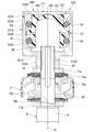
- a punch P2 having an outer diameter larger than the inner diameter of the hole 56 is pushed into the hole 56 to push the hole 56 on the inner circumference of the piston rod 8 into the hole 56.
- the diameter is increased to plastically deform the male screw 80 on the outer circumference of the piston rod 8.
- the rotation restricting portion 316 formed by plastically deforming the male screw 80 of the piston rod 8 is formed.
- both the male screw 80 of the piston rod 8 and the female screw 81 of the nut portion 91 of the nut member 82 may be plastically deformed by the punch P2.
- the cylindrical portion 302 and the annular portion 94 of the nut member 82 are radially inward from the outer peripheral side of the tubular portion 302 of the case member 83 with the punch P3.
- the case member 83 may be fixed to the nut member 82 by plastically deforming the cylindrical portion 302 and the annular portion 94. With this configuration, the case member 83 does not need a locking portion 303. Further, since it is possible to crimp from the same direction with the same punch in the second fastening step and the case member mounting step, manufacturing becomes easy.
- the second embodiment according to the present invention will be described mainly based on FIGS. 7 to 10, focusing on the differences from the first embodiment.
- the parts common to the first embodiment are represented by the same name and the same reference numerals.
- the central axis CL indicates the center line of the shock absorber and each component constituting the shock absorber.
- the damping force variable mechanism 58A which is partially different from the damping force variable mechanism 58, is provided in place of the damping force variable mechanism 58 with respect to the first embodiment.
- the damping force variable mechanism 58A is provided with a housing 85A which is partially different from the housing 85 instead of the housing 85.
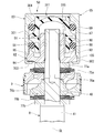
- the housing 85A includes a case member 321A and a lid member 322A.
- the case member 321A is made of metal such as iron and is formed mainly by cutting, and the nut portion 341A and the case portion 342A are seamlessly integrated.
- the nut portion 341A has a substantially cylindrical shape, and a female screw 81 similar to the above is formed on the inner peripheral portion thereof.
- the nut portion 341A surrounds one end of the piston rod 8 which is the inner end of the cylinder 4, and a female screw 81 screwed into the male screw 80 is formed.
- the case portion 342A has a cylindrical shape extending radially outward from one end side of the nut portion 341A in the axial direction and extending from the outer peripheral side of the substrate portion 351A to the side opposite to the nut portion 341A in the axial direction.
- the main body portion 352A, the cylindrical tubular portion 353A extending axially outward from the end opposite to the axial nut portion 341A of the main body portion 352A, and the axial main body portion 352A of the tubular portion 353A.
- Has a flat plate-shaped locking portion 354A extending inward in the radial direction of the tubular portion 353A from the opposite end.
- the nut portion 341A and the female screw 81 on the inner peripheral side thereof project from the substrate portion 351A of the case portion 342A toward the outside of the case portion 342A.
- the tubular portion 353A has the same outer diameter as the main body portion 352A and has a larger inner diameter. Therefore, the tubular portion 353A has a thinner cylindrical shape than the main body portion 352A.
- the main body portion 352A is formed with a cylindrical surface portion 96, an inclined surface portion 97, and a medium-diameter cylindrical surface portion 103 in this order from the substrate portion 351A side on the inner peripheral side.
- the O-rings 88 and 89 and the free piston 87 constituting the second damping force generation mechanism 311 are housed in the case portion 342A. Therefore, in the case member 321A of the housing 85A, the nut portion 341A fastened to the piston rod 8 and the case portion 342A for accommodating the internal unit parts O-rings 88 and 89 and the free piston 87 are seamlessly integrated. It is configured in.
- the lid member 322A is made of a metal such as iron, is formed mainly by cutting, and has an annular shape.
- the lid member 322A is fitted inside the tubular portion 353A, and is sandwiched from both sides in the axial direction by the main body portion 352A and the locking portion 354A.
- the lid member 322A is formed with an inclined surface portion 102 similar to the above on the inner peripheral side adjacent to the medium-diameter cylindrical surface portion 103, and is similar to the above on the side opposite to the medium-diameter cylindrical surface portion 103 of the inclined surface portion 102.
- the small-diameter cylindrical surface portion 101 of the above is formed.
- the manufacturing method of the present embodiment is also a method of assembling the piston 9 and the damping force variable mechanism 58A to the piston rod 8.
- a valve regulating member 77b, a disc valve 75b, and an interposing disc 76b are provided at the end of the piston rod 8 on the mounting shaft portion 40 side, as in the first embodiment.
- the locking portion 354A has the same tubular shape as the tubular portion 353A, and the nut portion 341A and the substrate portion 351A are the main portion 352A, the tubular portion 353A, and the locking portion 354A. It is oriented so as to be located on the piston 9 side in the axial direction.
- the valve regulating member 77b and the disc valve 75b are formed by the nut portion 341A of the case member 321A and the end portion of the main shaft portion 41 of the piston rod 8 on the mounting shaft portion 40 side.
- the intervening disc 76b, the piston 9, the intervening disc 76a, the disc valve 75a, and the valve regulating member 77a are sandwiched.
- This step is the first fastening step in which the case member 321A of the housing 85A is screwed and fastened to the male screw 80 of the piston rod 8.
- the step of performing this rotation regulation processing is the second fastening step.
- a rotation restricting portion 315A is formed in which at least one of the male screw 80 of the piston rod 8 and the female screw 81 of the nut portion 341A of the case member 321A is plastically deformed.
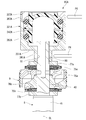
- the nut portion 341A and the mounting shaft are pressed by the punch P4 from the outer periphery of the nut portion 341A of the case member 321A via the nut portion 341A.
- the portion 40 is crimped inward in the radial direction.
- the female screw 81 of the nut portion 341A and the male screw 80 of the piston rod 8 are plastically deformed.
- the male screw 80 of the piston rod 8 and the female screw 81 of the nut portion 341A of the case member 321A are formed with a rotation restricting portion 315A in which both of them are plastically deformed.
- the rotation control unit 315A may be configured by plastically deforming only the female screw 81 of the case member 321A among the male screw 80 of the piston rod 8 and the female screw 81 of the case member 321A.
- the free piston 87 in which the O-rings 88 and 89 are pre-assembled is inserted into the case portion 342A of the case member 321A as shown in FIG. 7, and further, the free piston 87 and the tubular portion of the case member 321A are inserted.
- a storage step of inserting the lid member 322A between the 353A and the 353A is performed.
- the free piston 87 is oriented so that the piston bottom 109 is located on the opposite side of the piston 9 in the axial direction thereof.
- the lid member 322A is oriented so that the inclined surface portion 102 is located closer to the piston 9 than the small-diameter cylindrical surface portion 101 in the axial direction thereof.
- a crimping step is performed in which the locking portion 354A, which was cylindrical at this time, is plastically deformed inward in the radial direction to form a flat plate as shown in FIG.
- the case member 321A sandwiches the lid member 322A from both sides in the axial direction between the main body portion 352A and the locking portion 354A.
- the lid member 322A is integrated with the case member 321A to form the housing 85A. That is, in this crimping step, the locking portion 354A, which is the end portion of the case portion 342A, is crimped to the lid member 322A to fix the lid member 322A to the case portion 342A.
- the O-rings 88 and 89 and the free piston 87 constituting the second damping force generation mechanism 311 are housed in the housing 85A.
- the shock absorber 1 of the present embodiment has a rotation regulating portion 315A formed by plastically deforming at least one of the male screw 80 of the piston rod 8 and the nut portion 341A of the housing 85A. ..
- the housing 85A since a dedicated member for detenting the housing 85A is not required, an increase in the number of parts can be suppressed and an increase in manufacturing cost can be suppressed. In addition, the basic length of the shock absorber 1 can be shortened. Further, since it is not necessary to apply a coating for preventing loosening, the rotational torque can be stabilized and the occurrence of contamination can be suppressed.
- the housing 85A is integrally composed of a nut portion 341A fastened to the piston rod 8 and a case portion 342A for accommodating the O-rings 88 and 89 and the free piston 87, which are internal unit parts, and is secondly fastened.
- the piston rod 8 is pressed from the outer periphery of the nut portion 341A to plastically deform the male screw 80 of the piston rod 8.
- the housing 85A can be easily detented, an increase in manufacturing cost can be further suppressed.
- the case portion 342A has a storage step for accommodating the free piston 87, the O-ring 88, 89 and the lid member 322A, which are internal unit parts, and the end portion of the case portion 342A with respect to the lid member 322A. Includes a crimping step to crimp and fix. Therefore, the lid member 322A can be easily fixed to the case member 321A, and an increase in manufacturing cost can be further suppressed.
- At least one of the male screw 80 of the piston rod 8 and the female screw 81 of the nut portion 341A of the case member 321A performed in the second fastening step described above is plastically deformed to rotate the case member 321A with respect to the piston rod 8. It is also possible to change the rotation regulation processing to be regulated as follows.
- a punch P5 having an outer diameter larger than the inner diameter of the hole 56 is pushed into the hole 56 to push the hole 56 on the inner circumference of the piston rod 8 into the hole 56.
- the diameter is increased to plastically deform the male screw 80 on the outer circumference of the piston rod 8.
- the rotation restricting portion 316A formed by plastically deforming the male screw 80 of the piston rod 8 is formed.
- both the male screw 80 of the piston rod 8 and the female screw 81 of the nut portion 341A of the case member 321A may be plastically deformed by the punch P5.
- the tubular portion 353A which is the end portion of the case portion 342A is radially inward from the radial outside of the tubular portion 353A of the case portion 342A.
- the lid member 322A may be fixed to the case member 321A by plastically deforming the tubular portion 353A and the lid member 322A. With this configuration, the case member 321A does not need a locking portion 354A. Further, since the punches P4 and P6 can be simultaneously crimped from the same direction in the second fastening step and the crimping step, the manufacturing becomes easy.
- the first aspect of the present invention is a cylinder in which a working fluid is enclosed; the cylinder is provided in the cylinder, the inside of the cylinder is divided into two chambers, and the cylinder is moved by movement.
- a piston having a passage through which a working fluid flows out from one of the chambers; a piston rod having a male screw inserted into the piston and formed on one end side of the piston;
- a disk-shaped first damping force generating mechanism that generates the damping force; a nut portion that surrounds one end of the piston rod and is screwed into the male screw, and a second damping force generating mechanism that generates the damping force by the movement of the piston.
- a method of manufacturing a shock absorber comprising; a housing comprising a case portion for accommodating; a first fastening step of screwing and fastening the housing to the male screw of the piston rod; It has a second fastening step of plastically deforming at least one of the male screw and the nut portion of the housing to perform rotation restricting processing for restricting the rotation of the housing with respect to the piston rod. According to this manufacturing method, it is possible to suppress an increase in the number of parts.
- the housing comprises a nut member and a tubular case member; in the second fastening step, the piston rod is pressed from the outer periphery of the nut member.
- the male screw of the piston rod is plastically deformed.
- the housing is composed of a nut member and a tubular case member; in the second fastening step, the hole in the inner circumference of the piston rod is enlarged in diameter.
- the male screw is plastically deformed.
- a fourth aspect is, in the first aspect, a nut portion in which the housing is fastened to the piston rod, and a case portion in which an internal unit component is housed and integrally configured with the nut portion.
- the piston rod is pressed from the outer periphery of the nut portion to plastically deform the male screw of the piston rod.
- a fifth aspect is, in the fourth aspect, a storage step for accommodating the free piston, which is an internal unit component, an elastic member, and a lid member in the case portion; the case portion with respect to the lid member. Further has a crimping step and;
- the end portion of the case portion is crimped from the radial outside of the case portion in the crimping step.
- a seventh aspect of the present invention is a cylinder in which the working fluid is enclosed; a passage provided in the cylinder, which divides the inside of the cylinder into two chambers, and the working fluid flows out from one chamber in the cylinder by movement.
- a piston rod that is inserted through the piston and has a male screw formed on one end side of the piston; a disk-shaped first damping force generating mechanism that opens and closes the passage of the piston to generate a damping force.
- a housing having a nut portion that surrounds one end of the piston rod and is screwed into the male screw, and a case portion that houses a second damping force generating mechanism that generates a damping force by the movement of the piston.
- the shock absorber includes a rotation restricting portion formed by plastically deforming at least one of the male screw of the piston rod and the nut portion of the housing. According to this configuration, it is possible to suppress an increase in the number of parts.
Landscapes
- Engineering & Computer Science (AREA)
- General Engineering & Computer Science (AREA)
- Mechanical Engineering (AREA)
- Physics & Mathematics (AREA)
- Fluid Mechanics (AREA)
- Fluid-Damping Devices (AREA)
Abstract
この緩衝器の製造方法では、ピストンよりも一端側に形成された雄ねじを有するピストンロッドと;前記ピストンの通路を開閉し、減衰力を発生させるディスク状の第1減衰力発生機構と;前記ピストンロッドの一端を囲むとともに前記雄ねじに螺合されるナット部と、前記ピストンの移動により前記減衰力を発生させる第2減衰力発生機構を収納するケース部と、を備えるハウジングと;を有する緩衝器を、製造する。この緩衝器の製造方法は、前記ハウジングを前記ピストンロッドの前記雄ねじに螺合して締結する第1締結ステップと;前記ピストンロッドの前記雄ねじおよび前記ハウジングの前記ナット部のうちの少なくともいずれか一方を塑性変形させて前記ピストンロッドに対する前記ハウジングの回転を規制する回転規制加工を行う第2締結ステップと;を有する。
Description
本発明は、緩衝器の製造方法および緩衝器に関する。
本願は、2020年5月26日に、日本国に出願された特願2020-091424号に基づき優先権を主張し、その内容をここに援用する。
本願は、2020年5月26日に、日本国に出願された特願2020-091424号に基づき優先権を主張し、その内容をここに援用する。
緩衝器には、ピストンロッドのピストンから突出する部分に、内機部品を収容するハウジングを螺合させたものがある(例えば、特許文献1参照)。また、緩衝器には、ピストンロッドのピストンから突出する部分にナットを螺合させ、このナットを加締めることで、その緩みを規制したものがある(例えば、特許文献2参照)。
ところで、緩衝器において部品点数の増大を抑制する要望がある。
本発明は、部品点数の増大を抑制することができる緩衝器の製造方法および緩衝器の提供を目的とする。
上記目的を達成するために、本発明は以下の態様を採用した。
すなわち、本発明に係る第1の態様は、作動流体が封入されるシリンダと;前記シリンダ内に設けられ、前記シリンダ内を2室に区画し、移動により前記シリンダ内の一方の室から作動流体が流れ出す通路を有するピストンと;前記ピストンに挿通され、前記ピストンよりも一端側に形成された雄ねじを有するピストンロッドと;前記ピストンの前記通路を開閉し、減衰力を発生させるディスク状の第1減衰力発生機構と;前記ピストンロッドの一端を囲むとともに前記雄ねじに螺合されるナット部と、前記ピストンの移動により前記減衰力を発生させる第2減衰力発生機構を収納するケース部と、を備えるハウジングと;を有する緩衝器の製造方法であって、前記ハウジングを前記ピストンロッドの前記雄ねじに螺合して締結する第1締結ステップと;前記ピストンロッドの前記雄ねじおよび前記ハウジングの前記ナット部のうちの少なくともいずれか一方を塑性変形させて前記ピストンロッドに対する前記ハウジングの回転を規制する回転規制加工を行う第2締結ステップと;を有する。
すなわち、本発明に係る第1の態様は、作動流体が封入されるシリンダと;前記シリンダ内に設けられ、前記シリンダ内を2室に区画し、移動により前記シリンダ内の一方の室から作動流体が流れ出す通路を有するピストンと;前記ピストンに挿通され、前記ピストンよりも一端側に形成された雄ねじを有するピストンロッドと;前記ピストンの前記通路を開閉し、減衰力を発生させるディスク状の第1減衰力発生機構と;前記ピストンロッドの一端を囲むとともに前記雄ねじに螺合されるナット部と、前記ピストンの移動により前記減衰力を発生させる第2減衰力発生機構を収納するケース部と、を備えるハウジングと;を有する緩衝器の製造方法であって、前記ハウジングを前記ピストンロッドの前記雄ねじに螺合して締結する第1締結ステップと;前記ピストンロッドの前記雄ねじおよび前記ハウジングの前記ナット部のうちの少なくともいずれか一方を塑性変形させて前記ピストンロッドに対する前記ハウジングの回転を規制する回転規制加工を行う第2締結ステップと;を有する。
本発明に係る第2の態様は、作動流体が封入されるシリンダと;前記シリンダ内に設けられ、前記シリンダ内を2室に区画し、移動により前記シリンダ内の一方の室から作動流体が流れ出す通路を有するピストンと;前記ピストンに挿通され、前記ピストンよりも一端側に雄ねじが形成されたピストンロッドと;前記ピストンの前記通路を開閉し、減衰力を発生させるディスク状の第1減衰力発生機構と;前記ピストンロッドの一端を囲むとともに前記雄ねじに螺合されるナット部と、前記ピストンの移動により減衰力を発生させる第2減衰力発生機構を収納するケース部と、を有するハウジングと;を備える緩衝器であって、前記ピストンロッドの前記雄ねじおよび前記ハウジングの前記ナット部のうちの少なくともいずれか一方が塑性変形されて構成された回転規制部を有する。
本発明の上記各態様によれば、部品点数の増大を抑制できる。
[第1実施形態]
本発明に係る第1実施形態を、図1~図6に基づいて説明する。これら図面及び以下の説明において、中心軸線CLは、緩衝器及びこれを構成する各構成部品の中心線を示す。
本発明に係る第1実施形態を、図1~図6に基づいて説明する。これら図面及び以下の説明において、中心軸線CLは、緩衝器及びこれを構成する各構成部品の中心線を示す。
本実施形態の緩衝器(Shock Absorber)1は、作動流体として油液が用いられる油圧緩衝器である。緩衝器1は、図1に示すように、内筒2と外筒3とを有する複筒式のシリンダ4を備えている。外筒3は、内筒2より大径であり、内筒2を覆うように内筒2と同軸に配置されている。内筒2と外筒3との間の空間は、リザーバ室5となっている。なお、本発明は、複筒式に限らず単筒式の緩衝器にも適用することができる。
緩衝器1は、ピストンロッド8とピストン9とを有している。ピストン9は、ピストンロッド8の軸方向の一端部に連結されている。よって、ピストン9は、ピストンロッド8と一体的に移動する。ピストンロッド8は、内筒2および外筒3の中心軸線CL上に同軸に配置されている。ピストンロッド8は、その軸方向一端側が内筒2および外筒3(つまりシリンダ4)の内部に挿入され、その軸方向他端側が内筒2および外筒3(つまりシリンダ4)から外部に延出されている。ピストン9は、シリンダ4の内筒2内に摺動可能に設けられており、内筒2内を二つの室11および室12に区画している。言い換えれば、ピストン9は、シリンダ4内に摺動可能に設けられ、一端がシリンダ4の外部へ延出されたピストンロッド8の他端側に連結されている。ピストンロッド8は、室11,12のうち室11のみを貫通するように設けられている。
シリンダ4の内筒2内には、作動流体としての油液が封入される。また、シリンダ4内の内筒2と外筒3との間のリザーバ室5には、作動流体としての油液および高圧(20~30気圧程度)のガスが封入される。つまり、内筒2と外筒3とを有するシリンダ4には作動流体が封入されている。なお、リザーバ室5内には、高圧ガスに換えて大気圧の空気を封入してもよい。
緩衝器1は、ロッドガイド15とシール部材16と摩擦部材17とを有している。また、緩衝器1は、ベースバルブ18を有している。ロッドガイド15は、シリンダ4における、ピストンロッド8の外部突出側の端部位置に配置されている。ロッドガイド15は、段付き形状で、その大径側が外筒3の内側に嵌合されると共にその小径側が内筒2の内側に嵌合されている。シール部材16は、シリンダ4の端部であってかつ、シリンダ4の軸方向におけるロッドガイド15よりも外側に配置されている。摩擦部材17は、シール部材16とロッドガイド15との間に配置されている。ベースバルブ18は、シリンダ4内の軸方向に沿って見て、ロッドガイド15、シール部材16および摩擦部材17とは反対側の端部に配置されている。
ロッドガイド15、シール部材16および摩擦部材17は、いずれも、環状の形状を有する。ロッドガイド15、シール部材16および摩擦部材17のそれぞれの内側に、ピストンロッド8が摺動可能に挿通される。ロッドガイド15は、ピストンロッド8を、その径方向移動を規制しつつも軸方向には移動可能に支持しており、ピストンロッド8の移動を案内する。シール部材16は、その内周部が、軸方向に移動するピストンロッド8の外周部に摺接して、内筒2内の油液とリザーバ室5内の高圧ガスおよび油液とが外部に漏洩するのを防止する。摩擦部材17は、その内周部がピストンロッド8の外周部に摺接することで、ピストンロッド8に摩擦抵抗を与える。
シリンダ4の外筒3は、円筒状の胴部材21と底蓋部材22とからなっている。胴部材21の軸方向の一端に、底蓋部材22が嵌合されている。底蓋部材22は、胴部材21に嵌合された状態で、胴部材21に対して溶接により密閉状態となるように固定されている。
胴部材21は、底蓋部材22とは反対側が開口部27となっており、この開口部27に係止部28を有している。上記したシール部材16およびロッドガイド15は、胴部材21の開口部27側に嵌合されている。係止部28は、胴部材21における開口部27の端部位置から径方向内方に突出しており、シール部材16をロッドガイド15との間に挟持している。
底蓋部材22の内側には、ベースバルブ18のベースボディ30が配置されている。ベースボディ30は、シリンダ4内の室12と上記したリザーバ室5との間を画成する。ベースボディ30は、軸方向一側が他側よりも小径となる段差状をなしている。ベースボディ30は、その大径側において底蓋部材22に載置されており、径方向の位置が中心軸線CLと同軸をなすように位置決めされている。
シリンダ4の内筒2は、円筒状の形状を有する。内筒2は、その軸方向の一端側がベースバルブ18のベースボディ30の小径側に嵌合状態で支持されている。また、内筒2は、その軸方向の他端側が外筒3の開口部27の内側にあるロッドガイド15の小径側に嵌合した状態で、支持されている。
ベースバルブ18のベースボディ30には、その軸方向に貫通する挿通孔29が径方向の中央に形成されている。この挿通孔29の周囲には、ベースボディ30を軸方向に貫通する流通路31a,31bが形成されている。これら流通路31a,31bは、内筒2内の室12と、外筒3と内筒2との間のリザーバ室5との間を連通可能としている。また、ベースボディ30には、底蓋部材22とは反対側にディスクバルブ33aが配置され、また、底蓋部材22側にディスクバルブ33bが配置されている。ディスクバルブ33aは、チェックバルブであり、外側の流通路31aを開閉可能としている。ディスクバルブ33bは、減衰バルブであり、内側の流通路31bを開閉可能としている。ディスクバルブ33a,33bは、挿通孔29に挿入されるリベット35により径方向の内側部分がクランプされることで、ベースボディ30に取り付けられている。
ディスクバルブ33bは、ディスクバルブ33aの図示略の通路穴およびベースボディ30の流通路31bを介して室12からリザーバ室5側への油液の流れを許容して減衰力を発生する一方で、逆方向の油液の流れを規制する。これとは反対に、ディスクバルブ33aは、ベースボディ30の流通路31aを介してリザーバ室5から室12側への油液の流れを抵抗無く許容する一方で、逆方向の油液の流れを規制する。ディスクバルブ33bは、ピストンロッド8がシリンダ4への進入量を増大させる縮み側に移動することによってピストン9が室12側に移動した際、室12の圧力がリザーバ室5よりも所定値上昇すると、流通路31bを開き、その際に減衰力を発生する。よって、ディスクバルブ33bは、縮み側の減衰バルブとなっている。ディスクバルブ33aは、ピストンロッド8がシリンダ4からの突出量を増大させる伸び側に移動することによってピストン9が室11側に移動した際、室12の圧力がリザーバ室5よりも所定値下降すると、流通路31aを開くことになるが、その際にはリザーバ室5から室12内に実質的に減衰力を発生せずに油液を流す。よって、ディスクバルブ33aは、サクションバルブである。
ピストンロッド8が伸び側に移動して、そのシリンダ4からの突出量が増大すると、その分の油液が、リザーバ室5からディスクバルブ33aを開きつつ流通路31aを介して室12に流れる。逆に、ピストンロッド8が縮み側に移動して、そのシリンダ4への挿入量が増大すると、その分の油液が室12からディスクバルブ33bを開きつつ流通路31bを介してリザーバ室5に流れる。
なお、チェックバルブとしてのディスクバルブ33aで伸び側の減衰力を、積極的に発生させてもよい。また、これらのディスクバルブ33a,33bを廃止して、代わりにオリフィスを採用してもよい。
ピストンロッド8は、取付軸部40と、主軸部41とを有している。取付軸部40は、ピストン9が取り付けられる部分であり、ピストンロッド8のシリンダ4内への挿入先端側に形成されている。主軸部41は、ピストンロッド8の取付軸部40以外の部分であり、取付軸部40よりも大径となっている。ピストンロッド8は、主軸部41において、ロッドガイド15、シール部材16および摩擦部材17のそれぞれの内側に、摺動可能に挿通されている。主軸部41には、ロッドガイド15への挿入部分よりも取付軸部40側に、リテーナ42が、径方向外側に広がるように固定されている。リテーナ42の取付軸部40とは反対には、円環状の弾性材料からなる緩衝体43が、内側に主軸部41を挿通させた状態で設けられている。
図2に示すように、ピストン9には、複数(図2では断面図とした関係上、一カ所のみ図示)の通路50aと、複数(図2では断面図とした関係上、一カ所のみ図示)の通路50bとが設けられている。これら通路50aおよび通路50bは、室11と室12とを連通可能としている。
ピストン9の室11側への移動時、つまりピストンロッド8がシリンダ4から伸び出る伸び行程においては、通路50bに対して設けられた後述の第1減衰力発生機構51bが通路50bを閉塞する。このため、ピストン9の移動によって油液が、通路50aを通って、室11および室12の一方である室11から他方である室12に向けて流れ出す。言い換えれば、ピストン9が有する通路50aは、ピストン9が一方向に移動したときに、シリンダ4内の室11および室12のうちの一方である室11から作動流体が流れ出す。
他方、ピストン9の室12側への移動時、つまりピストンロッド8がシリンダ4内に進入する縮み行程においては、通路50aに対して設けられた後述の第1減衰力発生機構51aが通路50aを閉塞する。このため、ピストン9の移動によって油液が、通路50bを通って、室11および室12の他方である室12から一方である室11に向けて流れ出す。言い換えれば、ピストン9が有する通路50bは、ピストン9が他方向に移動したときに、シリンダ4内の室11および室12のうちの他方である室12から作動流体が流れ出す。ピストン9には、その円周方向において、通路50aと通路50bとが交互に形成されている。
複数の通路50aは、ピストン9の軸方向一側(室11側)が径方向外側に、軸方向他側(室12側)が径方向内側に開口している。そして、これら通路50aに、減衰力を発生させる第1減衰力発生機構51aが設けられている。第1減衰力発生機構51aは、ピストン9の軸方向の室12側に配置されている。通路50aは、上記したように伸び行程時に油液が室11から流れ出す、伸び側の通路を構成している。通路50aに対して設けられた第1減衰力発生機構51aは、伸び側の通路50aの油液の流動を抑制して減衰力を発生させる、伸び側の減衰力発生機構となっている。
複数の通路50bは、ピストン9の軸方向他側(室12側)が径方向外側に、軸方向一側(室11側)が径方向内側に開口している。そして、これら通路50bに、減衰力を発生させる第1減衰力発生機構51bが設けられている。第1減衰力発生機構51bは、ピストン9の軸方向の室11側に配置されている。通路50bは、上記した縮み行程時に油液が室12から流れ出す、縮み側の通路を構成している。通路50bに対して設けられた第1減衰力発生機構51bは、縮み側の通路50bの油液の流動を抑制して減衰力を発生させる、縮み側の減衰力発生機構となっている。
ピストンロッド8には、取付軸部40の位置に、取付軸部40を径方向に貫通する孔部55が形成されている。また、ピストンロッド8には、孔部55よりも大径の孔部56が軸方向に沿って孔部55の位置から主軸部41とは反対側の先端部まで形成されている。これら孔部55,56が、互いに連通して、ピストンロッド8に設けられるロッド内通路57を構成している。
ピストンロッド8には、取付軸部40のピストン9に対して主軸部41とは反対側に、減衰力可変機構58が取り付けられている。減衰力可変機構58は、ロッド内通路57の孔部56を覆うように取り付けられており、その内部がロッド内通路57に連通している。
上述の緩衝器1は、車両の各車輪それぞれに対して設けられる。その際に、例えば緩衝器1の一方側は車体により支持され、他方側が車輪側に固定される。具体的には、ピストンロッド8にて車体側に連結され、シリンダ4の外筒3側が車輪側に連結される。なお、上記とは逆に、緩衝器1の他方側が車体により支持されてかつ緩衝器1の一方側が車輪側に固定されるようにしても良い。
ピストン9は、略円板状のピストン本体61と、ピストン本体61の外周面に装着される摺接部材62とを有している。ピストン9は、摺接部材62においてシリンダ4の内筒2の内周面に摺接する。ピストン本体61には、径方向の中央に、軸方向に貫通するように挿通穴63が形成されている。そして、この挿通穴63に、ピストンロッド8の取付軸部40が挿通されている。このピストン本体61に、挿通穴63を囲むようにして、上記した通路50a,50bが形成されている。
ピストン本体61の軸方向の室12側の端部には、弁座71aが形成されている。弁座71aは、伸び側の通路50aの一端の開口位置の外側に、円環状に形成されている。ピストン本体61の軸方向の室11側の端部には、弁座71bが形成されている。弁座71bは、縮み側の通路50bの一端の開口位置の外側に、円環状に形成されている。弁座71aは、第1減衰力発生機構51aを構成している。弁座71bは、第1減衰力発生機構51bを構成している。
ピストン本体61において、弁座71aの挿通穴63とは反対側が、弁座71aよりも軸線方向高さが低くなっており、この部分に縮み側の通路50bの他端が開口している。また、同様に、ピストン本体61において、弁座71bの挿通穴63とは反対側が、弁座71bよりも軸線方向高さが低くなっており、この部分に伸び側の通路50aの他端が開口している。
第1減衰力発生機構51aは、上記した弁座71aと、弁座71aに着座可能な環状のディスクバルブ75aとから構成されている。ディスクバルブ75aは、複数枚の環状の単体ディスクが重ね合わせられることで構成されている。ディスクバルブ75aのピストン本体61側には、介装ディスク76aが配置されている。ディスクバルブ75aのピストン本体61とは反対側には、環状のバルブ規制部材77aが配置されている。介装ディスク76aは、複数枚の環状の単体ディスクが重ね合わせられることで構成されている。
第1減衰力発生機構51aは、弁座71aとディスクバルブ75aとの間に、これらが当接状態にあっても通路50aを室12に連通させる固定オリフィス78aを有している。固定オリフィス78aは、弁座71aに形成された溝あるいはディスクバルブ75aに形成された開口によって形成されている。ディスクバルブ75aは、弁座71aから離座することで通路50aを開放する。その際に、バルブ規制部材77aがディスクバルブ75aの開方向への規定以上の変形を規制する。第1減衰力発生機構51aは、通路50aに設けられ、ピストン9の室11側への摺動によって通路50aに生じる油液の流れを抑制して減衰力を発生させる。第1減衰力発生機構51aは、そのバルブがディスク状のディスクバルブ75aであり、ピストン9の通路50aを開閉して減衰力を発生させる。
同様に、第1減衰力発生機構51bは、上記した弁座71bと、弁座71bに着座可能な環状のディスクバルブ75bとから構成されている。ディスクバルブ75bも、複数枚の環状の単体ディスクが重ね合わせられることで構成されている。ディスクバルブ75bのピストン本体61側には、介装ディスク76bが配置されている。ディスクバルブ75bのピストン本体61とは反対側には、環状のバルブ規制部材77bが配置されている。バルブ規制部材77bは、ピストンロッド8の主軸部41の取付軸部40側の端面に当接している。
第1減衰力発生機構51bは、弁座71bとディスクバルブ75bとの間に、これらが当接状態にあっても通路50bを室11に連通させる固定オリフィス78bを有している。固定オリフィス78bは、弁座71bに形成された溝あるいはディスクバルブ75bに形成された開口によって形成されている。ディスクバルブ75bは、弁座71bから離座することで、通路50bを開放する。その際に、バルブ規制部材77bが、ディスクバルブ75bの開方向への規定以上の変形を規制する。第1減衰力発生機構51bは、通路50bに設けられ、ピストン9の室12側への摺動によって通路50bに生じる油液の流れを抑制して減衰力を発生させる。第1減衰力発生機構51bは、そのバルブがディスク状のディスクバルブ75bであり、ピストン9の通路50bを開閉して減衰力を発生させる。
介装ディスク76aを構成する単体ディスクのうち、最もピストン本体61側にある単体ディスクは、内周側が切り欠かれており、この切り欠き部分がディスク内通路70を構成している。ピストンロッド8の取付軸部40とピストン本体61の挿通穴63との間には、軸方向に延びる軸方向通路200が形成されている。ディスク内通路70は、この軸方向通路200と通路50aとの間を常時連通させる。ピストンロッド8のロッド内通路57を構成する孔部55は、軸方向通路200に常時連通している。
ピストン本体61は、室12側にあるピストン体201と、室11側にあるピストン体202との二部品からなっている。ピストン体201およびピストン体202は、互いに周方向および径方向に位置決めされてかつ相対回転不可とされた状態で、無端のバンド状により摺接部材62で一体化されている。これにより、ピストン体201,202および摺接部材62が一体となってピストン9を構成している。ピストン体201には、ピストン体202とは反対側に、上記した環状の弁座71aが形成されている。ピストン体202には、ピストン体201とは反対側に、上記した環状の弁座71bが形成されている。
ピストン体201には、上記した挿通穴63の一部を構成する貫通穴211が、径方向の中央にて軸方向に貫通して形成されている。ピストン体202には、挿通穴63の一部を構成する貫通穴212が、径方向の中央にて軸方向に貫通して形成されている。貫通穴212は、貫通穴211よりも小径となっている。ピストンロッド8の取付軸部40は、この貫通穴212に嵌合する。軸方向通路200は、ピストンロッド8の取付軸部40と、ピストン体201の貫通穴211との間に形成されている。
ピストンロッド8に設けられたロッド内通路57は、軸方向通路200を介して、ディスク内通路70と常時連通している。ディスク内通路70と軸方向通路200とロッド内通路57とは、通路50aを介して室11に常時連通している。
ピストンロッド8の取付軸部40には、孔部55よりも主軸部41とは反対の先端側に、雄ねじ80が形成されている。雄ねじ80は、ピストンロッド8の取付軸部40のピストン9よりも突出する端部側に形成されている。この雄ねじ80に、上記した減衰力可変機構58が螺合されている。減衰力可変機構58は、減衰力を発生させ、その際に周波数(振動状態)により外部から制御されることなく減衰力を可変とする周波数感応部である。減衰力可変機構58は、雄ねじ80に螺合された状態で、上記したバルブ規制部材77a、ディスクバルブ75a、介装ディスク76a、ピストン9、介装ディスク76b、ディスクバルブ75bおよびバルブ規制部材77bを、ピストンロッド8の主軸部41の端面との間に挟持する。
減衰力可変機構58は、ナット部材82と、これとは別体の筒状のケース部材83(ケース部)とからなるハウジング85と、フリーピストン87と、ゴム部材であるOリング88(弾性部材)と、ゴム部材であるOリング89(弾性部材)とで構成されている。
ナット部材82には、ピストンロッド8の雄ねじ80に螺合される雌ねじ81が形成されている。ケース部材83は、略円筒状をなしており、その一端開口側がナット部材82に接合される。ケース部材83内に、フリーピストン87とOリング88,89とが収容される。フリーピストン87は、ハウジング85内に、軸方向に移動可能に設けられている。Oリング88は、フリーピストン87とナット部材82との間に設けられている。Oリング88は、フリーピストン87がハウジング85に対して軸方向のナット部材82側へ移動したときに圧縮変形する、縮み側の弾性体となっている。Oリング89は、フリーピストン87とケース部材83との間に設けられている。Oリング89は、フリーピストン87がハウジング85に対して上記とは反対側へ移動したときに圧縮変形する、伸び側の弾性体となっている。なお、図2においては、便宜上、自然状態のOリング88,89を図示している。特にOリング89は、シールとしても機能するので、取り付けられた状態で常時、その断面が非円形に変形しているように配置されることが望ましい。上記したOリング88は、フリーピストン87が一方向へ移動したときに圧縮変形し、フリーピストン87の変位に対して抵抗力を発生する抵抗要素となっている。また、Oリング89は、フリーピストン87が他方向へ移動したときに圧縮変形し、フリーピストン87の変位に対して抵抗力を発生する抵抗要素となっている。
ナット部材82は、鉄等の金属製であり、切削加工を主体として形成される。ナット部材82は、ナット部91と基板部92と外筒部93と環状部94とを有している。ナット部91は略円筒状をなしており、その内周部に、上記した雌ねじ81が形成されている。ナット部91は、ピストンロッド8のシリンダ4内側の一端を囲んでおり、雄ねじ80に螺合される雌ねじ81が形成されている。基板部92は、このナット部91の軸方向の一端部から径方向外側に広がる有孔円板状をなしている。外筒部93は、基板部92の外周側からその軸方向にナット部91と同側に延出している。環状部94は、外筒部93の軸方向の基板部92と同側から径方向外側に、環状に突出している。環状部94は、その軸方向の外筒部93側の端部に、徐々に小径となって外筒部93に繋がるテーパ面部95を有している。ナット部91およびその内周側の雌ねじ81は、基板部92からの軸方向の突出長さが、外筒部93よりも長くなっている。
外筒部93の内周面は、基板部92側から順に、円筒面部96および傾斜面部97を有している。円筒面部96は、一定径をなしている。傾斜面部97は、円筒面部96に繋がっており、円筒面部96から軸方向に離れるほど大径となる円環状をなしている。傾斜面部97は、ナット部材82の中心軸線CLを含む面での断面が略円弧状をなしている。
ケース部材83は、鉄等の金属製であり、切削加工を主体として形成されるもので、略円筒状をなしている。ケース部材83は、円筒状の主体部301と、主体部301の軸方向の一端部から軸方向外方に延びる円筒状の筒状部302と、筒状部302の軸方向の主体部301とは反対側の端部から筒状部302の径方向における内側に広がる平板状の係止部303と、主体部301の軸方向の筒状部302とは反対側の端部から径方向内方に突出する内側環状突起304と、を有している。筒状部302は、主体部301に対し、外径が同等であり、内径が大径である。よって、筒状部302は、主体部301よりも薄肉の円筒状である。
ケース部材83の内周面には、軸方向一側から順に、小径円筒面部101、傾斜面部102、中径円筒面部103、テーパ面部105および大径円筒面部104が形成されている。小径円筒面部101は、一定径をなしている。傾斜面部102は、小径円筒面部101に繋がっており、小径円筒面部101から離れるほど大径となる円環状となっている。傾斜面部102は、ケース部材83の中心軸線CLを含む面での断面が略円弧状をなしている。小径円筒面部101および傾斜面部102は、内側環状突起304に形成されている。中径円筒面部103は、傾斜面部102に繋がっており、小径円筒面部101よりも大径の一定径をなしている。テーパ面部105は、中径円筒面部103に繋がっており、中径円筒面部103から離れるほど大径となるテーパ状となっている。中径円筒面部103およびテーパ面部105は、主体部301に形成されている。大径円筒面部104は、テーパ面部105に繋がっており、中径円筒面部103より大径の一定径をなしている。大径円筒面部104は、筒状部302に形成されている。なお、ケース部材83は円筒状であり、その内周面を断面円形とすることが望ましいが、外周面は、多角形等、断面非円形としてもよい。
ケース部材83は、係止部303が筒状部302と同一の円筒状をなす状態で、これらの内側に、ナット部材82が挿入される。そして、テーパ面部105に環状部94のテーパ面部95を当接させた状態で、ケース部材83の環状部94よりも軸方向の内側環状突起304とは反対側にある係止部303が径方向内側に折り曲げられることで、ケース部材83およびナット部材82が一体化されてハウジング85となる。ナット部材82の外筒部93は、ハウジング85において、中径円筒面部103よりも径方向内側に突出する円環状の小径部を構成しており、この部分に傾斜面部97が形成されている。また、ケース部材83の内側環状突起304は、ハウジング85において、中径円筒面部103よりも径方向内側に突出する円環状の小径部を構成しており、この部分に傾斜面部102が形成されている。ハウジング85において、これら傾斜面部97と傾斜面部102とが、軸方向に対向するように配置されている。減衰力可変機構58の外径、つまりハウジング85の外径は、内筒2の内径よりも、流路抵抗とならない程度に小さく設定されている。
フリーピストン87は、例えば合成樹脂材料により形成される一体成形品である。フリーピストン87は、略円筒状のピストン筒部108と、湾曲板状のピストン底部109とを有している。ピストン底部109は、ピストン筒部108の軸方向の一端側を閉塞するように形成されている。ピストン筒部108の軸方向のピストン底部109とは反対側は、開口部220となっている。フリーピストン87は、ピストン筒部108およびピストン底部109を有する有底筒状をなしている。フリーピストン87は、合成樹脂材料のみで形成されている。
ピストン筒部108には、軸方向の中間位置に径方向外方に突出する外側環状突出部110が形成されている。外側環状突出部110は、ピストン筒部108の外側環状突出部110を除く筒部本体部221よりも大径であって、筒部本体部221から径方向外方に突出する円環状をなしている。
ピストン筒部108の外周面には、軸方向の開口部220とは反対側から順に、テーパ面部112、小径円筒面部113、傾斜面部114、大径円筒面部115、傾斜面部116、小径円筒面部117およびテーパ面部118が形成されている。テーパ面部112、小径円筒面部113、小径円筒面部117およびテーパ面部118は、筒部本体部221に形成されている。傾斜面部114、大径円筒面部115および傾斜面部116は、外側環状突出部110に形成されている。
テーパ面部112は、軸方向に沿って小径円筒面部113とは反対側に向かうほど小径となるテーパ状をなしている。小径円筒面部113はテーパ面部112の大径側に繋がっており、一定径となっている。傾斜面部114は、小径円筒面部113に繋がっており、小径円筒面部113から軸方向に離れるほど大径となる円環状をなしている。大径円筒面部115は、傾斜面部114の大径側に繋がっており、小径円筒面部113より大径の一定径をなしている。傾斜面部114は、フリーピストン87の中心軸線CLを含む面での断面が略円弧状をなしている。
傾斜面部116は、大径円筒面部115に繋がっており、大径円筒面部115から離れるほど小径となる円環状をなしている。傾斜面部116の小径側には、小径円筒面部117が繋がっている。小径円筒面部117は、小径円筒面部113と同径の一定径となっている。テーパ面部118は、小径円筒面部117に繋がっており、軸方向に沿って小径円筒面部117とは反対側に向かうほど小径となるテーパ状をなしている。傾斜面部116は、フリーピストン87の中心軸線CLを含む面での断面が略円弧状をなしている。ピストン筒部108は、その軸線方向の中央位置を通る平面に対して鏡面対称の形状をなしている。
フリーピストン87には、通路穴119がフリーピストン87の周方向に間隔をあけて複数箇所、形成されている。通路穴119は、外側環状突出部110の軸方向の中央位置に形成されている。通路穴119は、ピストン筒部108の軸方向の外側環状突出部110の位置を径方向に貫通している。通路穴119は、ピストン筒部108の径方向において内側ほど小径となるように、若干窄まっている。通路穴119は、具体的には、フリーピストン87の周方向において180度異なる2箇所に形成されている。ピストン底部109は、径方向の中央側ほど軸方向において開口部220から離れるように、略球面状に湾曲している。
フリーピストン87は、ピストン底部109を軸方向のナット部材82とは反対側に配置するようにして、ハウジング85内に配置される。その際に、ナット部材82のナット部91が、ピストン筒部108内に開口部220側から挿入される。フリーピストン87は、ハウジング85内に配置された状態で、大径円筒面部115がケース部材83の中径円筒面部103を軸方向に摺動する。
フリーピストン87がハウジング85内に配置された状態で、ケース部材83の傾斜面部102とフリーピストン87の傾斜面部114とが、径方向の位置を重ね合わせて軸方向に対向する。加えて、ナット部材82の外筒部93の傾斜面部97と、フリーピストン87の傾斜面部116とが、径方向の位置を重ね合わせて軸方向に対向する。
そして、フリーピストン87の小径円筒面部113および傾斜面部114と、ケース部材83の傾斜面部102および中径円筒面部103との間に、Oリング89(図2においては自然状態を図示)が配置されている。言い換えれば、フリーピストン87の外側環状突出部110と、ハウジング85の内側環状突起304との間に、Oリング89が配置されている。このOリング89は、自然状態にあるとき、その中心軸線CLを含む面での断面が円形状を有している。Oリング89は、自然状態にあるとき、内径がフリーピストン87の小径円筒面部113よりも小径で、外径がケース部材83の中径円筒面部103よりも大径となっている。つまり、Oリング89は、フリーピストン87およびハウジング85の両方に対して、これらの径方向に沿った締め代をもって嵌合される。
また、ハウジング85の中径円筒面部103および傾斜面部97と、フリーピストン87の傾斜面部116および小径円筒面部117との間に、Oリング88(図2においては自然状態を図示)が配置されている。言い換えれば、フリーピストン87の外側環状突出部110とハウジング85の外筒部93との間に、Oリング88が配置されている。このOリング88は、自然状態にあるとき、その中心軸線CLを含む面での断面が円形状を有している。Oリング88は、自然状態にあるとき、内径がフリーピストン87の小径円筒面部117よりも小径で、外径がハウジング85の中径円筒面部103よりも大径となっている。つまり、Oリング88も、フリーピストン87およびハウジング85の両方に対してこれらの径方向に沿った締め代をもって嵌合される。
両方のOリング88,89は、同じ大きさを持つ共通部品である。Oリング88,89は、フリーピストン87を、ハウジング85内でハウジング85に対して軸方向の所定の中立位置に保持するように付勢する。それとともに、Oリング88,89は、弾性変形することによって、フリーピストン87のハウジング85に対する軸方向両側の移動を許容する。
減衰力可変機構58においては、ハウジング85とフリーピストン87とOリング88,89との間が、ハウジング内通路121となっている。通路50aの一部と、ディスク内通路70と、軸方向通路200と、ロッド内通路57と、ハウジング内通路121とが、二つの室11,12のうちの一方の室11に連通されるロッド側通路122を構成している。ロッド側通路122においては、ディスク内通路70がオリフィスとなっている。ロッド側通路122は、ピストン9の室11側への移動により室11の圧力が上昇すると、室11から油液が流れ出す。つまり、ピストン9の室11側への移動により、室11から、ロッド側通路122に油液が流れ出す。ハウジング85に形成されたハウジング内通路121は、内部がロッド側通路122の少なくとも一部の流路となっている。ハウジング85のケース部材83の内部に設けられたフリーピストン87およびOリング88,89は、ロッド側通路122に設けられてピストン9の移動により減衰力を発生させる、第2減衰力発生機構311を構成している。
ハウジング内通路121は、Oリング89とフリーピストン87とハウジング85とによって、ピストンロッド8側の室11に常時連通するロッド室側通路部123と、ボトム側の室12に常時連通するボトム室側通路部124とに画成されている。ロッド室側通路部123は、室125と通路穴119と室126とから構成されている。室125は、ナット部材82とフリーピストン87とOリング88とで囲まれており、ロッド内通路57が開口する。通路穴119は、フリーピストン87に形成されており、室125に一端が開口する。室126は、ケース部材83とOリング88とOリング89とフリーピストン87とで囲まれており、通路穴119の他端が開口する。ボトム室側通路部124は、ケース部材83の内側環状突起304側とOリング89とフリーピストン87とで囲まれた部分から構成されている。
伸び行程でピストン9が室11側へ移動すると、室11,12のうち、高圧となる室11の油液が、ロッド側通路122のうちの通路50aとディスク内通路70と軸方向通路200とロッド内通路57とロッド室側通路部123とに流れる。すると、フリーピストン87は、ボトム室側通路部124の油液を室12に排出しながら、ハウジング85に対して軸方向のナット部材82とは反対側へ移動する。その際に、フリーピストン87とハウジング85との間に設けられた一方のOリング89が、フリーピストン87の外側環状突出部110の傾斜面部114と、ハウジング85の内側環状突起304の傾斜面部102とに当接し、これらで挟まれて弾性変形させられる。つまり、この一方のOリング89は、伸び行程でのフリーピストン87の一方への移動に対して弾性力を発生する。
縮み行程でピストン9が室12側へ移動すると、室11,12のうちで高圧となる室12の油液がフリーピストン87を押圧する。すると、フリーピストン87がボトム室側通路部124へ油液を注入しながらハウジング85に対して軸方向のナット部材82側へ移動する。その際に、フリーピストン87とハウジング85との間に設けられた他方のOリング88が、フリーピストン87の外側環状突出部110の傾斜面部116と、ハウジング85の外筒部93の傾斜面部97とに当接し、これらで挟まれて弾性変形させられる。つまり、この他方のOリング88は、縮み行程でのフリーピストン87の他方への移動に対して弾性力を発生する。
フリーピストン87のピストン底部109は、室11,12のうち伸び行程で高圧となる室11側が曲面状に凹み、室11,12のうち縮み行程で高圧となる室12側が曲面状に突出している。
フリーピストン87の移動時に、Oリング89とフリーピストン87とハウジング85とが、ロッド室側通路部123とボトム室側通路部124とを画成する。よって、フリーピストン87およびOリング89は、ロッド側通路122を、ピストン9が伸び行程で一方向に移動したときの油液の流れの上流側の通路50a、ディスク内通路70、軸方向通路200、ロッド内通路57およびロッド室側通路部123と、下流側のボトム室側通路部124とに画成する。フリーピストン87およびOリング89は、ロッド側通路122を、ピストン9が縮み行程で他方向に移動したときの油液の流れの上流側のボトム室側通路部124と、下流側のロッド室側通路部123、ロッド内通路57、軸方向通路200、ディスク内通路70および通路50aと、に画成する。
ハウジング85の内部に設けられたフリーピストン87およびOリング88,89は、ロッド側通路122に設けられてピストン9の移動により減衰力を発生させる第2減衰力発生機構311を構成している。すなわち、第2減衰力発生機構311は、フリーピストン87の位置に応じてロッド側通路122の油液の流れを制御して減衰力を発生させる。よって、ハウジング85のケース部材83は、その内部に、第2減衰力発生機構311の内機部品であるフリーピストン87およびOリング88,89を収容する。
次に、以上に述べた緩衝器1の作動について説明する。
ピストンロッド8が伸び側に移動する伸び行程では、室11から通路50aを介して室12に油液が流れる。ピストン速度が微低速域の場合は、室11から通路50aに導入された油液が、基本的に、弁座71aと弁座71aに当接するディスクバルブ75aとの間に形成された、常時開口の固定オリフィス78aを介して室12に流れ、その際オリフィス特性(減衰力がピストン速度の2乗にほぼ比例する)の減衰力が発生する。また、ピストン速度が上昇して低速域に達すると、室11から通路50aに導入された油液が、基本的にディスクバルブ75aを開きながらディスクバルブ75aと弁座71aとの間を通って室12に流れる。このため、バルブ特性(減衰力がピストン速度にほぼ比例する)の減衰力が発生する。
ピストンロッド8が縮み側に移動する縮み行程では、室12から通路50bを介して室11に油液が流れる。ピストン速度が微低速域の場合は、室12から通路50bに導入された油液が、基本的に、弁座71bと弁座71bに当接するディスクバルブ75bとの間に形成された常時開口の固定オリフィス78bを介して室11に流れる。そして、その際に、オリフィス特性(減衰力がピストン速度の2乗にほぼ比例する)の減衰力が発生する。また、ピストン速度が上昇して低速域に達すると、室12から通路50bに導入された油液が、基本的にディスクバルブ75bを開きながらディスクバルブ75bと弁座71bとの間を通って室11に流れる。このため、バルブ特性(減衰力がピストン速度にほぼ比例する)の減衰力が発生する。
ここで、ピストン速度が遅いとき、つまり微低速域(例えば0.05m/s)の周波数が比較的高い領域(例えば7Hz以上)は、例えば路面の細かな表面の凹凸から生じる振動であり、このような状況では減衰力を下げるのが好ましい。また、同じくピストン速度が遅いときであっても、上記とは逆に周波数が比較的低い領域(例えば2Hz以下)は、いわゆる車体のロールによるぐらつき等の振動であり、このような状況では減衰力を上げるのが好ましい。
これに対応して、上記した減衰力可変機構58が、ピストン速度が同じように遅い場合でも、周波数に応じて減衰力を可変とする。つまり、ピストン速度が遅い時、ピストン9の往復動の周波数が高くなると、その伸び行程では、室11の圧力が高くなる。そして、ロッド側通路122のうち、通路50aとディスク内通路70と軸方向通路200とロッド内通路57とを介して、減衰力可変機構58のハウジング内通路121のロッド室側通路部123に、室11から油液を導入させながら、フリーピストン87が、軸方向の室12側にあるOリング89の付勢力に抗してハウジング85に対して軸方向の室12側に移動する。このようにフリーピストン87が軸方向の室12側に移動することにより、ハウジング内通路121に室11から油液を導入する。その結果、室11から通路50aに導入され第1減衰力発生機構51aを通過して室12に流れる油液の流量が減る。これにより、減衰力が下がる。その際に、ディスク内通路70の絞り効果により、減衰力可変機構58に流入する油液の量がコントロールされる。
続く縮み行程では、室12の圧力が高くなるため、ロッド側通路122のうち、ピストンロッド8のロッド内通路57と軸方向通路200とディスク内通路70と通路50aとを介して減衰力可変機構58のハウジング内通路121のロッド室側通路部123から室11に油液を排出させながら、それまで軸方向の室12側に移動していたフリーピストン87が軸方向の室11側にあるOリング88の付勢力に抗してハウジング85に対して軸方向の室11側に移動する。このようにフリーピストン87が軸方向の室11側に移動することにより、室12の容積を拡大する。その結果、室12から通路50bに導入され第1減衰力発生機構51bを通過して室11に流れる油液の流量が減る。これにより、減衰力が下がる。その際にも、ディスク内通路70の絞り効果により、減衰力可変機構58から排出される油液の量がコントロールされる。
ピストン9の周波数が高い領域では、フリーピストン87の移動の周波数も追従して高くなる。その結果、上記した伸び行程の度に、室11からハウジング内通路121のロッド室側通路部123に油液が流れ、縮み行程の度に、室12の容積がフリーピストン87の移動の分拡大することになる。よって、減衰力が下がった状態に維持される。
他方で、ピストン速度が遅い時、ピストン9の周波数が低くなると、フリーピストン87の移動の周波数も追従して低くなる。このため、伸び行程の初期に、室11からハウジング内通路121のロッド室側通路部123に油液が流れる。しかし、その後はフリーピストン87がOリング89を圧縮してハウジング85に対して軸方向の室12側で停止し、室11からハウジング内通路121のロッド室側通路部123に油液が流れなくなる。そのため、室11から通路50aに導入され第1減衰力発生機構51aを通過して室12に流れる油液の流量が減らない状態となり、減衰力が高くなる。
続く縮み行程でも、その初期に、室12の容積が、ハウジング85に対するフリーピストン87の移動の分、拡大することになる。しかし、その後はフリーピストン87がOリング88を圧縮してハウジング85に対して軸方向の室11側で停止し、室12の容積に影響しなくなる。そのため、室12から通路50bに導入され第1減衰力発生機構51bを通過して室11に流れる油液の流量が減らない状態となり、減衰力が高くなる。
次に、以上に述べた第1実施形態の緩衝器1の製造方法について説明する。本実施形態の製造方法は、ピストンロッド8にピストン9および減衰力可変機構58等を組み付ける方法を含む。
図3に示すように、ピストンロッド8の主軸部41の取付軸部40側の端部に、バルブ規制部材77bと、ディスクバルブ75bと、介装ディスク76bと、ピストン9と、介装ディスク76aと、ディスクバルブ75aと、バルブ規制部材77aとを、この順番で、それぞれの内側にピストンロッド8の取付軸部40を嵌合させて載置させる組み付けステップを行う。
次に、この状態で、バルブ規制部材77aよりもピストン9とは反対側に突出する取付軸部40の雄ねじ80に、ナット部材82の雌ねじ81を螺合させる。この時、ナット部材82は、基板部92をナット部91および外筒部93よりもピストン9側に位置させる向きとされる。そして、ナット部材82を所定のトルクで締め付けることで、ナット部材82の基板部92と、ピストンロッド8の主軸部41の取付軸部40側の端部とで、バルブ規制部材77b、ディスクバルブ75b、介装ディスク76b、ピストン9、介装ディスク76a、ディスクバルブ75aおよびバルブ規制部材77aを軸方向に挟持する。このステップが、ハウジング85のナット部材82をピストンロッド8の雄ねじ80に螺合して締結する第1締結ステップとなる。
次に、ピストンロッド8の雄ねじ80およびナット部材82のナット部91の雌ねじ81のうちの少なくともいずれか一方を塑性変形させて、ピストンロッド8に対するナット部材82の回転を規制する回転規制加工を行う。この回転規制加工を行うステップが、第2締結ステップとなる。第2締結ステップを行うことにより、ピストンロッド8の雄ねじ80およびナット部材82のナット部91の雌ねじ81のうちの少なくともいずれか一方が塑性変形されてなる回転規制部315が形成される。
ここで、第2締結ステップは、図3に示すように、ポンチP1で、ナット部材82のナット部91の外周からナット部91を介してピストンロッド8を押圧するようにナット部91および取付軸部40を径方向内方に加締めて、ナット部91の雌ねじ81とピストンロッド8の雄ねじ80とを塑性変形させる。これにより、ピストンロッド8の雄ねじ80およびナット部材82の雌ねじ81に、これらの両方が塑性変形されてなる回転規制部315が形成される。この回転規制部315によって、ピストンロッド8に対するナット部材82の回転が規制される。なお、回転規制部315は、ピストンロッド8の雄ねじ80およびナット部材82の雌ねじ81のうちのナット部材82の雌ねじ81のみが塑性変形されて構成されていても良い。
ここで、上記した各ステップとは別に、係止部303が筒状をなす状態のケース部材83の内部に、Oリング88,89およびフリーピストン87を、Oリング88,89の摩擦力で予め組み付けておく。すなわち、まず、ケース部材83内にOリング89を挿入する。次に、これらケース部材83およびOリング89の内側に、フリーピストン87を嵌合させる。次に、ケース部材83とフリーピストン87との間に、Oリング88を挿入する。
そして、上記のように内部にOリング88,89およびフリーピストン87が予め組み付けられた状態のケース部材83の、筒状をなす係止部303および筒状部302を、ナット部材82に被せる。すると、ケース部材83は、図4に示すように主体部301のテーパ面部105を、ナット部材82のテーパ面部95に当接させて停止する。この状態で、筒状部302が、ナット部材82の環状部94と軸方向の位置を重ね合わせて環状部94を径方向外側で覆うことになる。この時点では、筒状をなしている係止部303が環状部94よりも軸方向のピストン9側に突出する。
次に、筒状をなす係止部303を径方向内方に塑性変形させて、図4に示すように平板状にするケース部材装着ステップを行う。これにより、ケース部材83は、主体部301と係止部303とでナット部材82の環状部94を軸方向両側から挟持する。その結果、ケース部材83がナット部材82と一体となってハウジング85を構成する。この状態で、このハウジング85内には、第2減衰力発生機構311を構成するOリング88,89およびフリーピストン87が収納されている。
特許文献1には、ピストンロッドのピストンから突出する部分に、内機部品を収容するハウジングを螺合させる緩衝器が記載されている。また、特許文献2には、ピストンロッドのピストンから突出する部分にナットを螺合させ、このナットを加締めることで、その緩みを規制する緩衝器が記載されている。ところで、緩衝器において、部品点数の増大を抑制する要望がある。
本実施形態の製造方法は、ハウジング85のナット部91をピストンロッド8の雄ねじ80に螺合して締結する第1締結ステップと、ピストンロッド8の雄ねじ80およびハウジング85のナット部91のうちの少なくともいずれか一方を塑性変形させてピストンロッド8に対するハウジング85の回転を規制する回転規制加工を行う第2締結ステップと、を含む。言い換えれば、本実施形態の緩衝器1は、ピストンロッド8の雄ねじ80およびハウジング85のナット部91のうちの少なくともいずれか一方が塑性変形されて構成される回転規制部315を有する、構成とした。
よって、本実施形態は、ハウジング85の回り止めを行うための専用の部材(例えばダブルナット構造とするためのナット)が不要となるため、部品点数の増大を抑制することができ、製造コストの増大を抑制することができる。加えて、緩衝器1の基本長を短くすることができる。さらに、緩み止め用のコーティングを施す必要がないため、回転トルクを安定化できるとともに、コンタミネーションの発生を抑制することができる。
また、ハウジング85は、ナット部材82と、筒状のケース部材83とから構成され、第2締結ステップでは、ナット部材82の外周からピストンロッド8を押圧してピストンロッド8の雄ねじ80を塑性変形させる。言い換えれば、回転規制部315が、ピストンロッド8の雄ねじ80を塑性変形させて構成されている。
よって、ハウジング85の回り止めを容易に行うことができるため、製造コストの増大を一層抑制することができる。
なお、上記した第2締結ステップにおいて行う、ピストンロッド8の雄ねじ80およびナット部材82のナット部91のうちの少なくともいずれか一方を塑性変形させてピストンロッド8に対するナット部材82の回転を規制する回転規制加工を、以下のように変更することも可能である。
すなわち、第2締結ステップとして、図5に示すように、孔部56の内径よりも外径が大径のポンチP2を、孔部56に押し込んで、ピストンロッド8の内周の孔部56を拡径させてピストンロッド8の外周の雄ねじ80を塑性変形させる。これにより、ピストンロッド8の雄ねじ80に、これが塑性変形されてなる回転規制部316が形成される。なお、この場合、ポンチP2でピストンロッド8の雄ねじ80およびナット部材82のナット部91の雌ねじ81の両方を塑性変形させても良い。
また、ケース部材装着ステップにおいて、図6に示すように、ポンチP3で、ケース部材83の筒状部302の外周側から、筒状部302とナット部材82の環状部94とを径方向内方に加締めて、これら筒状部302および環状部94を塑性変形させることにより、ケース部材83をナット部材82に固定するようにしても良い。このように構成すれば、ケース部材83に係止部303が不要となる。また、第2締結ステップとケース部材装着ステップとにおいて同じポンチで同じ方向から加締めることが可能となるため、製造が容易となる。
[第2実施形態]
次に、本発明に係る第2実施形態を、主に図7~図10に基づいて、上記第1実施形態との相違部分を中心に説明する。なお、上記第1実施形態と共通する部位については、同一称呼、同一の符号で表す。また、各図面及び以下の説明において、中心軸線CLは、緩衝器及びこれを構成する各構成部品の中心線を示す。
次に、本発明に係る第2実施形態を、主に図7~図10に基づいて、上記第1実施形態との相違部分を中心に説明する。なお、上記第1実施形態と共通する部位については、同一称呼、同一の符号で表す。また、各図面及び以下の説明において、中心軸線CLは、緩衝器及びこれを構成する各構成部品の中心線を示す。
本第2実施形態においては、上記第1実施形態に対して、減衰力可変機構58に換えて、これとは一部が異なる減衰力可変機構58Aが設けられている。減衰力可変機構58Aには、ハウジング85に換えて、これとは一部が異なるハウジング85Aが設けられている。ハウジング85Aは、ケース部材321Aと蓋部材322Aとからなっている。
ケース部材321Aは、鉄等の金属製であって切削加工を主体として形成されるもので、ナット部341Aとケース部342Aとが継ぎ目なく一体となっている。ナット部341Aは、略円筒状をなしており、その内周部に、上記と同様の雌ねじ81が形成されている。ナット部341Aは、ピストンロッド8のシリンダ4内側の端部となる一端を囲んでおり、雄ねじ80に螺合される雌ねじ81が形成されている。
ケース部342Aは、ナット部341Aの軸方向の一端側から径方向外方に広がる基板部351Aと、基板部351Aの外周側から軸方向のナット部341Aとは反対側に延出する筒状の主体部352Aと、主体部352Aの軸方向のナット部341Aとは反対側の端部から軸方向外方に延びる円筒状の筒状部353Aと、筒状部353Aの軸方向の主体部352Aとは反対側の端部から筒状部353Aの径方向の内側に広がる平板状の係止部354Aと、を有している。ナット部341Aおよびその内周側の雌ねじ81は、ケース部342Aの基板部351Aからケース部342Aの外方に向けて突出している。筒状部353Aは、主体部352Aに対し、外径が同等であり、内径が大径である。よって、筒状部353Aは、主体部352Aよりも薄肉の円筒状である。主体部352Aには、内周側に、基板部351A側から順に、上記と同様の円筒面部96と傾斜面部97と中径円筒面部103とが形成されている。
ケース部342A内には、第2減衰力発生機構311を構成するOリング88,89およびフリーピストン87が収納される。よって、ハウジング85Aのケース部材321Aは、ピストンロッド8に締結されるナット部341Aと、内部に内機部品であるOリング88,89およびフリーピストン87を収納するケース部342Aとが、継ぎ目なく一体に構成されている。
蓋部材322Aは、鉄等の金属製であり、切削加工を主体として形成されるもので、円環状である。蓋部材322Aは、筒状部353Aの内側に嵌合されており、主体部352Aと係止部354Aとにより軸方向両側から挟持されている。蓋部材322Aには、内周側に、中径円筒面部103と隣り合って上記と同様の傾斜面部102が形成されており、傾斜面部102の中径円筒面部103とは反対側に上記と同様の小径円筒面部101が形成されている。
次に、本第2実施形態の製造方法について説明する。本実施形態の製造方法も、ピストンロッド8にピストン9および減衰力可変機構58A等を組み付ける方法となっている。
図8に示すように、ピストンロッド8の主軸部41の取付軸部40側の端部に、上記第1実施形態と同様に、バルブ規制部材77bと、ディスクバルブ75bと、介装ディスク76bと、ピストン9と、介装ディスク76aと、ディスクバルブ75aと、バルブ規制部材77aとを、この順番で、それぞれの内側にピストンロッド8の取付軸部40を嵌合させて載置させる組み付けステップを行う。
次に、この状態で、バルブ規制部材77aよりもピストン9とは反対側に突出する取付軸部40の雄ねじ80に、ケース部材321Aのナット部341Aの雌ねじ81を螺合させる。この時点では、ケース部材321Aは、係止部354Aが筒状部353Aと同一の筒状をなす状態であり、ナット部341Aおよび基板部351Aを主体部352A、筒状部353Aおよび係止部354Aよりも軸方向のピストン9側に位置させる向きとされる。そして、ケース部材321Aを所定のトルクで締め付けることで、ケース部材321Aのナット部341Aと、ピストンロッド8の主軸部41の取付軸部40側の端部とにより、バルブ規制部材77b、ディスクバルブ75b、介装ディスク76b、ピストン9、介装ディスク76a、ディスクバルブ75aおよびバルブ規制部材77aを挟持する。このステップが、ハウジング85Aのケース部材321Aをピストンロッド8の雄ねじ80に螺合して締結する第1締結ステップとなる。
次に、ピストンロッド8の雄ねじ80およびケース部材321Aのナット部341Aの雌ねじ81のうちの少なくともいずれか一方を塑性変形させて、ピストンロッド8に対するケース部材321Aの回転を規制する回転規制加工を行う。この回転規制加工を行うステップが、第2締結ステップとなる。第2締結ステップを行うことにより、ピストンロッド8の雄ねじ80およびケース部材321Aのナット部341Aの雌ねじ81のうちの少なくともいずれか一方が塑性変形されてなる回転規制部315Aが形成される。
ここで、第2締結ステップは、図8に示すように、ポンチP4で、ケース部材321Aのナット部341Aの外周からナット部341Aを介してピストンロッド8を押圧するようにナット部341Aおよび取付軸部40を径方向内方に加締める。これにより、ナット部341Aの雌ねじ81とピストンロッド8の雄ねじ80とを塑性変形させる。これにより、ピストンロッド8の雄ねじ80およびケース部材321Aのナット部341Aの雌ねじ81に、これらの両方が塑性変形されてなる回転規制部315Aが形成される。その結果、ピストンロッド8に対するケース部材321Aの回転が規制された状態になる。なお、回転規制部315Aは、ピストンロッド8の雄ねじ80およびケース部材321Aの雌ねじ81のうち、ケース部材321Aの雌ねじ81のみが塑性変形されて構成されても良い。
次に、Oリング88,89が予め組み付けられた状態のフリーピストン87を、図7に示すようにケース部材321Aのケース部342Aに挿入し、さらに、フリーピストン87とケース部材321Aの筒状部353Aとの間に蓋部材322Aを挿入する収納ステップを行う。このとき、フリーピストン87は、その軸方向において、ピストン底部109がピストン9とは反対側に位置する向きとされる。また、このとき、蓋部材322Aは、その軸方向において、傾斜面部102が小径円筒面部101よりもピストン9側に位置する向きとされる。
次に、この時点では筒状をなしていた係止部354Aを径方向内方に塑性変形させて、図7に示すように平板状にする加締めステップを行う。これにより、ケース部材321Aは、主体部352Aと係止部354Aとで蓋部材322Aを軸方向両側から挟持する。その結果、蓋部材322Aがケース部材321Aと一体となってハウジング85Aを構成する。すなわち、この加締めステップは、蓋部材322Aに対して、ケース部342Aの端部である係止部354Aを加締めて蓋部材322Aをケース部342Aに固定する。このハウジング85A内には、第2減衰力発生機構311を構成するOリング88,89およびフリーピストン87が収納されている。
本実施形態は、ハウジング85Aのナット部341Aをピストンロッド8の雄ねじ80に螺合して締結する第1締結ステップと、ピストンロッド8の雄ねじ80およびハウジング85Aのナット部341Aのうちの少なくともいずれか一方を塑性変形させてピストンロッド8に対するハウジング85Aの回転を規制する回転規制加工を行う第2締結ステップと、を含む。言い換えれば、本実施形態の緩衝器1は、ピストンロッド8の雄ねじ80およびハウジング85Aのナット部341Aのうちの少なくともいずれか一方が塑性変形されて構成される回転規制部315Aを有する、構成とした。
よって、本実施形態は、ハウジング85Aの回り止めを行うための専用の部材が不要になるため、部品点数の増大を抑制することができ、製造コストの増大を抑制することができる。加えて、緩衝器1の基本長を短くすることができる。さらに、緩み止め用のコーティングを施す必要がないため、回転トルクを安定化できるとともに、コンタミネーションの発生を抑制することができる。
また、ハウジング85Aは、ピストンロッド8に締結されるナット部341Aと、内部に内機部品であるOリング88,89およびフリーピストン87を収納するケース部342Aとが一体に構成され、第2締結ステップでは、ナット部341Aの外周からピストンロッド8を押圧してピストンロッド8の雄ねじ80を塑性変形させる。
よって、ハウジング85Aの回り止めを容易に行うことができるため、製造コストの増大を一層抑制することができる。
また、本実施形態では、ケース部342Aに、内機部品であるフリーピストン87、Oリング88,89および蓋部材322Aを収納する収納ステップと、蓋部材322Aに対してケース部342Aの端部を加締めて固定する加締めステップと、を含む。そのため、蓋部材322Aをケース部材321Aに容易に固定することができ、製造コストの増大を一層抑制することができる。
なお、上記した第2締結ステップにおいて行う、ピストンロッド8の雄ねじ80およびケース部材321Aのナット部341Aの雌ねじ81のうちの少なくともいずれか一方を塑性変形させてピストンロッド8に対するケース部材321Aの回転を規制する回転規制加工を、以下のように変更することも可能である。
すなわち、第2締結ステップとして、図9に示すように、孔部56の内径よりも外径が大径のポンチP5を、孔部56に押し込んで、ピストンロッド8の内周の孔部56を拡径させてピストンロッド8の外周の雄ねじ80を塑性変形させる。これにより、ピストンロッド8の雄ねじ80に、これが塑性変形されてなる回転規制部316Aが形成される。なお、この場合、ポンチP5でピストンロッド8の雄ねじ80およびケース部材321Aのナット部341Aの雌ねじ81の両方を塑性変形させても良い。
また、加締めステップにおいて、図10に示すように、ポンチP6で、ケース部342Aの筒状部353Aの径方向外方から、ケース部342Aの端部である筒状部353Aを径方向内方に加締めて、筒状部353Aおよび蓋部材322Aを塑性変形させることにより、ケース部材321Aに蓋部材322Aを固定するようにしても良い。このように構成すれば、ケース部材321Aに係止部354Aが不要となる。また、第2締結ステップと加締めステップとにおいてポンチP4,P6で同じ方向から同時に加締めを行うことができるため、製造が容易となる。
以上に述べた各実施形態のように、本発明の第1の態様は、作動流体が封入されるシリンダと;前記シリンダ内に設けられ、前記シリンダ内を2室に区画し、移動により前記シリンダ内の一方の室から作動流体が流れ出す通路を有するピストンと;前記ピストンに挿通され、前記ピストンよりも一端側に形成された雄ねじを有するピストンロッドと;前記ピストンの前記通路を開閉し、減衰力を発生させるディスク状の第1減衰力発生機構と;前記ピストンロッドの一端を囲むとともに前記雄ねじに螺合されるナット部と、前記ピストンの移動により前記減衰力を発生させる第2減衰力発生機構を収納するケース部と、を備えるハウジングと;を有する緩衝器の製造方法であって、前記ハウジングを前記ピストンロッドの前記雄ねじに螺合して締結する第1締結ステップと;前記ピストンロッドの前記雄ねじおよび前記ハウジングの前記ナット部のうちの少なくともいずれか一方を塑性変形させて前記ピストンロッドに対する前記ハウジングの回転を規制する回転規制加工を行う第2締結ステップと;を有する。
この製造方法によれば、部品点数の増大を抑制することができる。
この製造方法によれば、部品点数の増大を抑制することができる。
第2の態様は、第1の態様において、前記ハウジングが、ナット部材と、筒状のケース部材とから構成され;前記第2締結ステップで、前記ナット部材の外周から前記ピストンロッドを押圧して前記ピストンロッドの前記雄ねじを塑性変形させる。
第3の態様は、第1の態様において、前記ハウジングが、ナット部材と、筒状のケース部材とから構成され;前記第2締結ステップで、前記ピストンロッドの内周の孔部を拡径させて前記雄ねじを塑性変形させる。
第4の態様は、第1の態様において、前記ハウジングが、前記ピストンロッドに締結されるナット部と、内部に内機部品を収納するとともに前記ナット部と一体に構成されたケース部と、を有し;前記第2締結ステップで、前記ナット部の外周から前記ピストンロッドを押圧して前記ピストンロッドの前記雄ねじを塑性変形させる。
第5の態様は、第4の態様において、前記ケース部に、前記内機部品であるフリーピストンと、弾性部材と、蓋部材とを収納する収納ステップと;前記蓋部材に対して前記ケース部の端部を加締めて固定する加締めステップと;をさらに有する。
第6の態様は、第5の態様において、前記加締めステップで、前記ケース部の径方向外方から前記ケース部の端部を加締める。
本発明の第7の態様は、作動流体が封入されるシリンダと;前記シリンダ内に設けられ、前記シリンダ内を2室に区画し、移動により前記シリンダ内の一方の室から作動流体が流れ出す通路を有するピストンと;前記ピストンに挿通され、前記ピストンよりも一端側に雄ねじが形成されたピストンロッドと;前記ピストンの前記通路を開閉し、減衰力を発生させるディスク状の第1減衰力発生機構と;前記ピストンロッドの一端を囲むとともに前記雄ねじに螺合されるナット部と、前記ピストンの移動により減衰力を発生させる第2減衰力発生機構を収納するケース部と、を有するハウジングと;を備える緩衝器であって、前記ピストンロッドの前記雄ねじおよび前記ハウジングの前記ナット部のうちの少なくともいずれか一方が塑性変形されて構成された回転規制部を有する。
この構成によれば、部品点数の増大を抑制することができる。
この構成によれば、部品点数の増大を抑制することができる。
本発明の緩衝器の製造方法および緩衝器によれば、部品点数の増大を抑制できる。よって、産業上の利用可能性は大である。
1 緩衝器
4 シリンダ
8 ピストンロッド
9 ピストン
11,12 室
50a,50b 通路
51a,51b 第1減衰力発生機構
56 孔部
80 雄ねじ
82 ナット部材
83 ケース部材(ケース部)
85,85A ハウジング
87 フリーピストン(内機部品)
88,89 Oリング(内機部品,弾性部材)
91,341A ナット部
311 第2減衰力発生機構
315,316,315A,316A 回転規制部
322A 蓋部材(内機部品)
342A ケース部
4 シリンダ
8 ピストンロッド
9 ピストン
11,12 室
50a,50b 通路
51a,51b 第1減衰力発生機構
56 孔部
80 雄ねじ
82 ナット部材
83 ケース部材(ケース部)
85,85A ハウジング
87 フリーピストン(内機部品)
88,89 Oリング(内機部品,弾性部材)
91,341A ナット部
311 第2減衰力発生機構
315,316,315A,316A 回転規制部
322A 蓋部材(内機部品)
342A ケース部
Claims (7)
- 作動流体が封入されるシリンダと;
前記シリンダ内に設けられ、前記シリンダ内を2室に区画し、移動により前記シリンダ内の一方の室から作動流体が流れ出す通路を有するピストンと;
前記ピストンに挿通され、前記ピストンよりも一端側に形成された雄ねじを有するピストンロッドと;
前記ピストンの前記通路を開閉し、減衰力を発生させるディスク状の第1減衰力発生機構と;
前記ピストンロッドの一端を囲むとともに前記雄ねじに螺合されるナット部と、前記ピストンの移動により前記減衰力を発生させる第2減衰力発生機構を収納するケース部と、を備えるハウジングと;
を有する緩衝器を製造する方法であって、
前記ハウジングを前記ピストンロッドの前記雄ねじに螺合して締結する第1締結ステップと;
前記ピストンロッドの前記雄ねじおよび前記ハウジングの前記ナット部のうちの少なくともいずれか一方を塑性変形させて前記ピストンロッドに対する前記ハウジングの回転を規制する回転規制加工を行う第2締結ステップと;
を有することを特徴とする緩衝器の製造方法。 - 前記ハウジングが、ナット部材と、筒状のケース部材とから構成され;
前記第2締結ステップで、前記ナット部材の外周から前記ピストンロッドを押圧して前記ピストンロッドの前記雄ねじを塑性変形させる;
ことを特徴とする請求項1に記載の緩衝器の製造方法。 - 前記ハウジングが、ナット部材と、筒状のケース部材とから構成され;
前記第2締結ステップで、前記ピストンロッドの内周の孔部を拡径させて前記雄ねじを塑性変形させる;
ことを特徴とする請求項1に記載の緩衝器の製造方法。 - 前記ハウジングが、前記ピストンロッドに締結されるナット部と、内部に内機部品を収納するとともに前記ナット部と一体に構成されたケース部と、を有し;
前記第2締結ステップで、前記ナット部の外周から前記ピストンロッドを押圧して前記ピストンロッドの前記雄ねじを塑性変形させる;
ことを特徴とする請求項1に記載の緩衝器の製造方法。 - 前記ケース部に、前記内機部品であるフリーピストンと、弾性部材と、蓋部材とを収納する収納ステップと;
前記蓋部材に対して前記ケース部の端部を加締めて固定する加締めステップと;
をさらに有することを特徴とする請求項4に記載の緩衝器の製造方法。 - 前記加締めステップで、前記ケース部の径方向外方から前記ケース部の端部を加締める
ことを特徴とする請求項5に記載の緩衝器の製造方法。 - 作動流体が封入されるシリンダと;
前記シリンダ内に設けられ、前記シリンダ内を2室に区画し、移動により前記シリンダ内の一方の室から作動流体が流れ出す通路を有するピストンと;
前記ピストンに挿通され、前記ピストンよりも一端側に雄ねじが形成されたピストンロッドと;
前記ピストンの前記通路を開閉し、減衰力を発生させるディスク状の第1減衰力発生機構と;
前記ピストンロッドの一端を囲むとともに前記雄ねじに螺合されるナット部と、前記ピストンの移動により減衰力を発生させる第2減衰力発生機構を収納するケース部と、を有するハウジングと;
を備える緩衝器であって、
前記ピストンロッドの前記雄ねじおよび前記ハウジングの前記ナット部のうちの少なくともいずれか一方が塑性変形されて構成された回転規制部を有する
ことを特徴とする緩衝器。
Applications Claiming Priority (2)
| Application Number | Priority Date | Filing Date | Title |
|---|---|---|---|
| JP2020-091424 | 2020-05-26 | ||
| JP2020091424 | 2020-05-26 |
Publications (1)
| Publication Number | Publication Date |
|---|---|
| WO2021240936A1 true WO2021240936A1 (ja) | 2021-12-02 |
Family
ID=78723314
Family Applications (1)
| Application Number | Title | Priority Date | Filing Date |
|---|---|---|---|
| PCT/JP2021/007891 Ceased WO2021240936A1 (ja) | 2020-05-26 | 2021-03-02 | 緩衝器の製造方法および緩衝器 |
Country Status (1)
| Country | Link |
|---|---|
| WO (1) | WO2021240936A1 (ja) |
Citations (4)
| Publication number | Priority date | Publication date | Assignee | Title |
|---|---|---|---|---|
| JP2006336816A (ja) * | 2005-06-06 | 2006-12-14 | Kayaba Ind Co Ltd | 緩衝装置 |
| JP2012137168A (ja) * | 2010-12-28 | 2012-07-19 | Hitachi Automotive Systems Ltd | 緩衝器 |
| JP2015117713A (ja) * | 2013-12-16 | 2015-06-25 | カヤバ工業株式会社 | ショックアブソーバ及びショックアブソーバの製造方法 |
| JP2017187110A (ja) * | 2016-04-06 | 2017-10-12 | Kyb株式会社 | 緩衝器及び緩衝器の製造方法 |
-
2021
- 2021-03-02 WO PCT/JP2021/007891 patent/WO2021240936A1/ja not_active Ceased
Patent Citations (4)
| Publication number | Priority date | Publication date | Assignee | Title |
|---|---|---|---|---|
| JP2006336816A (ja) * | 2005-06-06 | 2006-12-14 | Kayaba Ind Co Ltd | 緩衝装置 |
| JP2012137168A (ja) * | 2010-12-28 | 2012-07-19 | Hitachi Automotive Systems Ltd | 緩衝器 |
| JP2015117713A (ja) * | 2013-12-16 | 2015-06-25 | カヤバ工業株式会社 | ショックアブソーバ及びショックアブソーバの製造方法 |
| JP2017187110A (ja) * | 2016-04-06 | 2017-10-12 | Kyb株式会社 | 緩衝器及び緩衝器の製造方法 |
Similar Documents
| Publication | Publication Date | Title |
|---|---|---|
| US10619694B2 (en) | Shock absorber | |
| JP5468465B2 (ja) | 緩衝器 | |
| JP6942185B2 (ja) | 緩衝器およびその製造方法 | |
| JP6838768B2 (ja) | 緩衝器 | |
| WO2018168865A1 (ja) | 減衰力調整式緩衝器 | |
| WO2018163868A1 (ja) | 緩衝器 | |
| WO2018061726A1 (ja) | 減衰力調整式緩衝器 | |
| US12571451B2 (en) | Shock absorber | |
| US12410847B2 (en) | Shock absorber | |
| JP7055236B2 (ja) | 緩衝器 | |
| US12066075B2 (en) | Shock absorber | |
| WO2017175785A1 (ja) | 緩衝器及び緩衝器の製造方法 | |
| US20220099153A1 (en) | Shock absorber | |
| JP5894874B2 (ja) | 緩衝器 | |
| WO2016194548A1 (ja) | 緩衝器 | |
| JP6803924B2 (ja) | 緩衝器 | |
| JP6789004B2 (ja) | 緩衝器 | |
| US20240376957A1 (en) | Damping force generation mechanism | |
| JP7814532B2 (ja) | ショックアブソーバおよびショックアブソーバの製造方法 | |
| JP2024021172A (ja) | シリンダ装置およびバルブ装置 | |
| JP7805197B2 (ja) | シリンダ装置 | |
| JP2020159391A (ja) | 緩衝器 | |
| WO2025177910A1 (ja) | シリンダ装置 | |
| JP2000179607A (ja) | 油圧緩衝器 | |
| CN116783406A (zh) | 缓冲器 |
Legal Events
| Date | Code | Title | Description |
|---|---|---|---|
| 121 | Ep: the epo has been informed by wipo that ep was designated in this application |
Ref document number: 21812545 Country of ref document: EP Kind code of ref document: A1 |
|
| NENP | Non-entry into the national phase |
Ref country code: DE |
|
| 122 | Ep: pct application non-entry in european phase |
Ref document number: 21812545 Country of ref document: EP Kind code of ref document: A1 |
|
| NENP | Non-entry into the national phase |
Ref country code: JP |