WO2021235010A1 - モータ制御装置及びモータ制御方法 - Google Patents
モータ制御装置及びモータ制御方法 Download PDFInfo
- Publication number
- WO2021235010A1 WO2021235010A1 PCT/JP2021/003175 JP2021003175W WO2021235010A1 WO 2021235010 A1 WO2021235010 A1 WO 2021235010A1 JP 2021003175 W JP2021003175 W JP 2021003175W WO 2021235010 A1 WO2021235010 A1 WO 2021235010A1
- Authority
- WO
- WIPO (PCT)
- Prior art keywords
- rotation
- command
- motor
- rotation speed
- signal
- Prior art date
- Legal status (The legal status is an assumption and is not a legal conclusion. Google has not performed a legal analysis and makes no representation as to the accuracy of the status listed.)
- Ceased
Links
Images









Classifications
-
- H—ELECTRICITY
- H02—GENERATION; CONVERSION OR DISTRIBUTION OF ELECTRIC POWER
- H02P—CONTROL OR REGULATION OF ELECTRIC MOTORS, ELECTRIC GENERATORS OR DYNAMO-ELECTRIC CONVERTERS; CONTROLLING TRANSFORMERS, REACTORS OR CHOKE COILS
- H02P23/00—Arrangements or methods for the control of AC motors characterised by a control method other than vector control
- H02P23/03—Arrangements or methods for the control of AC motors characterised by a control method other than vector control specially adapted for very low speeds
-
- H—ELECTRICITY
- H02—GENERATION; CONVERSION OR DISTRIBUTION OF ELECTRIC POWER
- H02P—CONTROL OR REGULATION OF ELECTRIC MOTORS, ELECTRIC GENERATORS OR DYNAMO-ELECTRIC CONVERTERS; CONTROLLING TRANSFORMERS, REACTORS OR CHOKE COILS
- H02P27/00—Arrangements or methods for the control of AC motors characterised by the kind of supply voltage
- H02P27/04—Arrangements or methods for the control of AC motors characterised by the kind of supply voltage using variable-frequency supply voltage, e.g. inverter or converter supply voltage
- H02P27/06—Arrangements or methods for the control of AC motors characterised by the kind of supply voltage using variable-frequency supply voltage, e.g. inverter or converter supply voltage using DC to AC converters or inverters
- H02P27/08—Arrangements or methods for the control of AC motors characterised by the kind of supply voltage using variable-frequency supply voltage, e.g. inverter or converter supply voltage using DC to AC converters or inverters with pulse width modulation
Definitions
- the present invention relates to a motor control device and a motor control method.
- a DC motor In automobiles, a DC motor is used as an electric drive source in order to use a battery as a power source.
- DC commutator motors that use brush commutators have been the mainstream, but with the development of power electronics in recent years, brushless DC motors are becoming widespread.
- the brushless DC motor detects the magnetic pole position by a rotation angle sensor such as a Hall IC or an encoder, and controls the voltage applied to the motor coil based on the detected rotation angle. This eliminates the need for a brush, which is advantageous for the brushless DC motor in terms of miniaturization and long life.
- microcomputer which is more expensive than the drive circuit of a brushed DC motor, as a drive circuit.
- microcomputer dedicated motor driver ICs for drive control are becoming available at low prices, and the system cost is also decreasing.
- Patent Document 1 discloses a technique for improving the stability of valve timing control by appropriately setting a control signal for instructing an actuator to operate.
- the control device corresponds to the combination of the operation direction and the selected control mode in the operation instruction according to a predetermined value predetermined for each expected combination of the operation direction and the control mode. Set the duty ratio of the pulse wave operation instruction signal.
- variable valve timing control device is a rotation-synchronized type in which a cam attached to the rotation shaft of the motor opens and closes the valve. If the angle of rotation of the cam does not change with respect to the angle of rotation of the engine, the motor maintains rotation synchronized with the engine.
- the valve opening or closing timing can be controlled by changing the rotation angle of the motor corresponding to the rotation angle of the engine.
- a variable valve timing controller with such a configuration must realize rapid valve opening or closing timing changes, and the speed range that the motor must realize is from the high speed side to the low speed side near zero speed. It reaches. In some cases, it is also required to reverse the direction of rotation. Moreover, it is required to realize these motor controls at low cost.
- the present invention has been made in view of the above circumstances, and an object of the present invention is to use a motor driver having a restriction on the minimum rotation speed and to realize the operation of the motor at the set minimum rotation speed or less of the motor driver. ..
- the motor control device of one aspect of the present invention is a motor control device that controls the rotation of the motor by supplying a PWM signal to the motor driver that drives the motor.
- the predetermined number of pulses of the PWM signal is set as a command unit, and the normal rotation signal generation period and the reverse rotation signal generation period are included in the command unit, and the rotation direction of the current motor rotation shaft is included in the normal rotation signal generation period.
- a motor control command creation device that outputs a forward rotation speed command in the same direction and a reverse rotation speed command in the direction opposite to the rotation direction of the current motor rotation shaft to the motor driver according to the target rotation speed during the reverse rotation signal generation period. Be prepared.
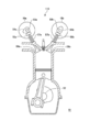
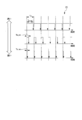
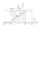
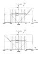
- the figure which shows the whole structure example of the motor control device which concerns on 1st Embodiment of this invention is shown. It is a block diagram which shows the configuration example of the hardware of the upper control microcomputer provided in the motor control apparatus which concerns on 1st Embodiment of this invention. It is a schematic sectional drawing which shows the structural example of the internal combustion engine provided with the variable valve timing control device. It is a waveform diagram for demonstrating the problem of motor control using a general PWM signal. As an example of the characteristics of the motor driver, it is a figure which shows the correspondence example of the duty ratio of the rotation speed command signal, and a motor speed (motor rotation speed). It is a figure which shows the operation example of the variable valve timing control device provided in the internal combustion engine.
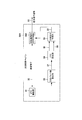
- FIG. 1 shows an overall configuration example of a motor control device according to the first embodiment of the present invention.
- FIG. 2 is a block diagram showing a configuration example of the hardware of the upper control microcomputer included in the motor control device.
- FIG. 3 is a schematic cross-sectional view showing a configuration example of an internal combustion engine provided with a variable valve timing control device.
- FIG. 1 describes an example in which a power conversion device controlled by the method of the present invention is used as an inverter for driving a three-phase motor.
- the motor control device 100 includes a power conversion device 14, a motor driver 20, and a host control microcomputer 30.
- the motor 10 to be controlled is a brushless DC motor.
- the motor 10 is connected to a motor shaft 11 that transmits the generated torque.
- the brushless DC motor determines the timing at which voltage is applied to each winding by the rotation angle sensor 12.
- the rotation angle sensor 12 an absolute encoder, a resolver, or the like can be used, but in the present embodiment, a Hall IC is used in consideration of realizing the motor control device 100 at low cost.
- the Hall IC outputs information in the magnetic flux direction as a digital signal.
- An AC voltage is applied from the power conversion device 14 to the wiring 13 of each phase of the motor 10.
- the power conversion device 14 includes a plurality of (for example, 6) switching elements 15 and converts the DC voltage Vdc into an AC voltage by turning the switching elements 15 on and off to create an AC voltage applied to the wiring 13. ..
- the DC current detector 16 measures the current flowing in or out of the power conversion device 14. Generally, a shunt resistor is inserted between the grounding point AGND and the negative electrode side connection terminal of the switching element 15, and the current is detected by measuring the voltage across the shunt resistor.
- the switching element 15 is turned ON / OFF by the gate voltage 18 created by the gate driver 17.
- the gate driver 17 amplifies the gate signal 19 that determines the ON / OFF timing of the switching element 15 and converts it into a voltage and a current that enable the switching element 15 to operate.
- the motor driver 20 creates a gate signal 19 for operating the motor 10 according to the rotation speed command signal 21 and the direction command signal 22 from the upper control system.
- the rotation number command signal 21 is given as a PWM signal, and represents the value of the rotation number command (for example, rpm) by the duty ratio (ratio of the ON signal time to the period).
- the direction command signal 22 is generally a digital signal, and for example, when it is 5V, it is a forward rotation command, and when it is 0V, it is a reverse rotation command. In the following description, when the direction command signal 22 is ON, it is represented as “1”, and when it is OFF, it is represented as “0”.
- clockwise is defined as forward rotation
- counterclockwise is defined as inversion toward the motor rotation axis.
- the motor driver 20 uses the rotation angle sensor signal 23 and the DC current signal 24 as other inputs.
- the rotation angle sensor signal 23 is the output of the rotation angle sensor 12, and the DC current signal 24 is the output of the DC current detector 16.
- the upper control microcomputer 30 is a control device constituting the upper control system, and creates a rotation speed command signal 21 and a direction command signal 22 of the motor 10.
- the host control microcomputer 30 receives a sensor signal for detecting an engine state such as an engine speed (not shown) and an engine temperature (not shown) as an input, and uses an electric VTC (VTC: variable timing camshaft).
- VTC variable timing camshaft
- the speed command 32 is input to the rotation speed command signal creating unit 36 and the forward / reverse pulse number setting unit 33.
- the motor speed is the rotation speed and is synonymous with the rotation speed.
- the number of revolutions means the number of revolutions per unit time.
- the host control microcomputer 30 includes a forward / reverse pulse number setting unit 33, an FRC (Free Running Counter) setting unit 34, a direction command creation unit 35, and a rotation speed command signal creation unit 36.
- FRC Free Running Counter
- the forward / reverse pulse number setting unit 33 is included in the forward rotation signal generation period and the inverting signal generation period (see FIG. 10 to be described later) in the direction command signal 22 based on the speed command 32 output by the VTC control unit 31.
- the number of pulses of the number command signal 21 is set, and the setting result is output to the FRC setting unit 34.
- the FRC setting unit 34 calculates the switching timing from normal rotation to reverse rotation and from reverse rotation to normal rotation based on the setting result of the pulse number of the rotation speed command signal 21, and notifies the direction command creation unit 35.
- the direction command creating unit 35 creates a direction command signal 22 from the switching timing information received from the FRC setting unit 34 and outputs the direction command signal 22 to the motor driver 20.
- direction command creating unit 35 also outputs the direction command signal 22 to the rotation speed command signal creating unit 36.
- the rotation speed command signal creation unit 36 creates a rotation speed command signal 21 based on the speed command 32 and the direction command signal 22, and outputs the rotation speed command signal 21 to the motor driver 20.
- the above-mentioned forward / reverse pulse number setting unit 33 sets the forward rotation pulse number 37 based on the speed command 32.
- the forward rotation pulse number 37 is defined as the number of pulses of the rotation number command signal 21 included in the section in which the direction command signal 22 represents the forward rotation direction.
- the FRC setting unit 34 uses the information of the number of forward rotation pulses 37 to generate a switching signal indicating the switching timing of the direction command signal 22.
- the forward / reverse switching signal 38 notifies the direction command creating unit 35 of the timing at which the direction command signal 22 switches from forward rotation to reverse rotation.
- the anti-positive switching signal 39 notifies the direction command creating unit 35 of the timing at which the direction command signal 22 switches from inversion to forward rotation.
- the motor 10 is attached to the variable valve timing control device 110 (see FIG. 3). As shown in FIG. 3, the variable valve timing control device 110 is provided in the engine 51.
- the variable valve timing control device 110 includes an intake side electric valve timing control motor 10a and an exhaust side electric valve timing control motor 10b.
- the intake side camshaft 53a is attached to the intake side electric valve timing control motor 10a via an appropriate speed reducer (not shown). Further, the exhaust side camshaft 53b is attached to the exhaust side electric valve timing control motor 10b via an appropriate speed reducer (not shown).
- the intake cam 54a opens the intake valve 56a by pushing the intake valve stem end 55a. When the intake cam 54a rotates to a position where the intake valve stem end 55a is not pushed, the intake valve 56a is closed by the intake valve spring 57a. The same applies even if it is on the exhaust side.
- the exhaust cam 54b opens the exhaust valve 56b by pushing the exhaust valve stem end 55b. When the exhaust cam 54b rotates to a position where the exhaust valve stem end 55b is not pushed, the exhaust valve 56b is closed by the exhaust valve spring 57b.
- the variable valve timing control device 110 shown in FIG. 3 is a system called a rotation synchronization type.
- the intake side cam shaft 53a and the exhaust side cam shaft 53b are normally controlled to rotate in synchronization with the crank shaft 52.
- the "synchronous state" means that the camshaft makes one rotation with respect to the rotation of the crankshaft 52, and the valve opening start angle and the valve opening end angle are always the same crankshaft angle. It is defined as being controlled by.
- variable valve timing control device 110 the rotation speed of the intake side electric valve timing control motor 10a is momentarily increased from the synchronized state, and when the desired valve opening start angle is reached, the intake is restored to the synchronized state.
- the timing can be advanced. This is referred to as "advance angle”.
- the intake timing can be delayed by momentarily delaying the rotation speed of the intake side electric valve timing control motor 10a from the synchronous state and returning to the synchronous state again when the desired valve opening start angle is reached. This is referred to as "retarded angle”.
- the exhaust valve side can be controlled in exactly the same way.
- ⁇ cmd is a target speed command output by the host control microcomputer 30. Note that this information includes information in the rotation direction, and is defined as forward rotation when ⁇ cmd is positive and inversion (reverse) when ⁇ cmd is negative, for example.
- Sgn is a function that returns 1 when the argument is positive and -1 when the argument is negative.
- Smax is the maximum value of the motor rotation speed assumed by the motor driver 20.
- the motor rotation speed is defined as the absolute value of the motor speed. Assuming that the maximum motor speed is ⁇ max, the maximum motor rotation speed is abs ( ⁇ max).
- Abs is a function that returns the absolute value of the argument. In this embodiment, a brushless DC motor is assumed, and it is assumed that there is no difference in characteristics between forward rotation and reverse rotation.
- Smin is the minimum value (set minimum rotation speed) of the motor rotation speed that can be realized by the motor driver 20 by normal PWM control.
- Rmin is the minimum rotation speed ratio and is defined as Smin / Smax.
- Rcmd is the target rotation speed ratio and is defined as Scmd / Smax.
- Scmd is abs ( ⁇ cmd).
- the present invention controls the motor speed by utilizing the fact that the rotation of the motor does not immediately reverse due to inertia even if the rotation direction command is switched from forward rotation to reverse rotation. Therefore, the present invention is characterized in that when the motor 10 is driven at an extremely low speed, the direction command signal 22 is switched ON / OFF for a certain period (command unit time Tunit) as shown in FIGS. 8 and 10 described later. do. Therefore, when driving at an extremely low speed, the direction command signal 22 is also output as a PWM signal like the rotation speed command signal 21. The PWM cycle of the direction command signal 22 is longer than the PWM cycle of the rotation speed command signal 21.
- the command unit includes pulses of a plurality of rotation speed command signals 21, and the number thereof is defined as the command unit division number N.
- the period in which the direction command signal 22 in one command unit indicates "forward rotation” is defined as "Tp”
- the number of pulses of the rotation speed command signal 21 included in the period Tp is defined as the number of normal rotation pulses np.
- the period in which the direction command signal 22 in one command unit indicates "inversion” is defined as "Tn”
- the number of pulses of the rotation speed command signal 21 included in the period Tn is defined as the number of inversion pulses nn.
- Tunit is called the command unit time
- Tp is called the forward rotation signal generation period
- Tn is called the inversion signal generation period.
- the PWM cycle is described as “Ts”
- the ON period is described as “Ts_on”
- the OFF period is described as “Ts_off”.
- the method of determining ON / OFF of the rotation speed command signal 21 and the direction command signal 22 is arbitrary, but for the sake of simplicity, "1" is set to ON and "0" is set to OFF.
- the duty ratio Dspd of the rotation speed command signal 21 can be written as Ts_on / Ts or (1-Ts_off) / Ts.
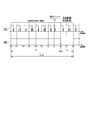
- FIG. 4 is a waveform diagram for explaining a problem of motor control using a general PWM signal.
- FIG. 4 shows an example of transmitting a rotation speed command signal 21 using PWM, and shows a case where the rotation speed command is small from top to bottom.
- the ON period Ts_on with respect to the PWM cycle is large, and even if noise is mixed, there is little malfunction.
- the ON period Ts_on becomes smaller and the pulse width becomes smaller. If the pulse width becomes too narrow, the pulse cannot be distinguished from noise.
- the energization pattern is switched according to the rotation angle of the motor, and a magnetic pole position sensor (rotation angle sensor 12) is used for that purpose.
- a magnetic pole position sensor rotating angle sensor 12
- the rotation speed is calculated by the reciprocal of the change time of the output signal of the magnetic pole position sensor. Due to this principle, when the actual speed of the motor is slow, the change time of the output signal of the magnetic pole position sensor becomes very large, and the magnetic pole position sensor acquires the rotation speed within the time that can be used as speed feedback. Is difficult.
- the specifications for inexpensive motor driver ICs are such that the minimum rotation speed (set minimum rotation speed) that can be achieved is restricted.
- This minimum rotation speed corresponds to the motor rotation speed Smin in FIG.
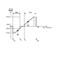
- FIG. 5 shows an example of correspondence between the duty ratio of the rotation speed command signal 21 and the motor speed (motor rotation speed) as an example of the characteristics of the motor driver 20.
- the horizontal axis represents the duty ratio [%] of the rotation speed command signal 21, and the vertical axis represents the interpretation (motor rotation speed) of the motor driver 20 when the rotation speed command signal 21 is received.
- the motor driver 20 operates to realize the rotation speed Smax when receiving the rotation speed command signal 21 having a duty ratio of 100%, and realizes the rotation speed Smin (set minimum rotation speed) when the duty ratio is Ds_min. Try to work.
- Ds_min is the minimum duty ratio (set minimum duty ratio) that can be realized by the motor driver 20.
- the motor driver 20 sets the rotation speed to 0.
- the motor driver 20 can operate at a rotation speed of 0 and a rotation speed of Smin or more and Smax or less.
- Such characteristics are not particularly problematic when operation at a constant rotation speed such as a pump is expected. However, such characteristics may cause difficulty in achieving the target operation in an application such as the variable valve timing control device 110 which is the subject of the present invention.
- FIG. 6 shows an operation example of the variable valve timing control device 110 included in the internal combustion engine (engine 51). Since both the intake side and the exhaust side operate in the same manner, the subscripts "a" and "b" shown in FIG. 3 are not distinguished here, and are described as, for example, a motor 10, a cam 104, and the like.
- the motor 10 rotates in synchronization with the rotation speed of the engine 51.
- one process of intake-compression-explosion-exhaust is completed in two revolutions (720 degrees).
- the cam 104 rotates one rotation (360 degrees). Therefore, when it is not necessary to change the timing of opening and closing the valve, the motor 10 rotates at half the rotation speed of the engine 51.
- FIG. 6 The upper side of FIG. 6 is a graph 61 showing the time change of the valve phase angle, and the lower side of FIG. 6 is a graph 62 showing the time change of the motor speed. It is assumed that the engine speed is constant. Further, the valve phase angle is set to 0 degree when it is a camshaft angle with respect to the crankshaft angle in the normal operating state. Since the intake side and the exhaust side are exactly the same, the intake and exhaust are not distinguished from now on.
- the motor speed When changing from the latest retard angle to the most advanced angle, the motor speed temporarily increases from the synchronous rotation speed and then returns to the synchronous rotation speed. This makes it possible to change the valve phase angle to the maximum advance angle. After lowering the motor speed from this state, the valve phase angle can be changed to the slowest angle by returning to the synchronous rotation speed again.
- the motor speed When changing from the advance angle side to the retard angle side, the motor speed will be lowered, but at this time, depending on the synchronous rotation speed determined from the engine speed and the request response up to the latest retard angle, the motor A situation occurs in which the number of revolutions becomes very small. In some cases, the motor may switch from normal rotation to reverse rotation.
- FIG. 7 shows a setting example of the forward / reverse pulse number setting unit 33 of the upper control microcomputer 30.
- the host control microcomputer 30A stores the relationship between the speed command 32 shown in FIG. 7 and the number of forward rotation pulses 37.
- the motor driver 20 can operate with the conventional design. Therefore, in this region, it is not necessary to switch between the forward rotation command and the reverse rotation command, and the direction command signal 22 is always a forward rotation command when Smin ⁇ ⁇ ⁇ Smax and a reverse rotation command when -Smax ⁇ ⁇ ⁇ -Smin. Further, in the region of Smin ⁇ ⁇ ⁇ Smax, the number of normal rotation pulses np is determined as a stepped waveform that increases or decreases by 1 at intervals of 2 ⁇ Smin / N as shown in FIG. 7 by increasing or decreasing the speed command 32.
- the command unit division number N is set to “10”, but the larger the command unit division number N, the higher the resolution of the motor speed in the low speed region (-Smin ⁇ ⁇ ⁇ Smin).
- the forward rotation pulse number 37 is not output to the FRC setting unit 34 but is output to the motor driver 20, and the motor driver 20 executes processing based on the forward rotation pulse number 37.
- the number of forward rotation pulses np is "10"
- the number of forward rotation pulses included in the command unit is 10. That is, since the motor 10 is driven only by the forward rotation pulse in the command unit time Tunit (see FIG. 10), it is the same as the general PWM control.
- the forward rotation pulse number np can be set to "0", that is, the inversion pulse number nn can be set to "10" in the same manner.
- FIG. 8 shows an operation example of the FRC setting unit 34 and the direction command creation unit 35 of the host control microcomputer 30.
- the vertical axis on the upper side of FIG. 8 represents FRC
- the horizontal axis represents time
- the lower side of FIG. 8 shows a waveform diagram of the direction command signal 22.
- the FRC is a free running counter, which is a signal that counts up by 1 at regular time intervals ( ⁇ frc). The FRC is reset when the overflow count FRC_ovf is reached, and the count-up is restarted from 0 again.
- the FRC setting unit 34 outputs a forward / reverse switching signal 38 for notifying the ON / OFF timing of the direction command signal 22 and a reverse / forward switching signal 39.
- the FRC is counted from 0 (time t0), and when the FRC count value reaches the switching count number FRC_chg (time t1), the forward / reverse switching signal 38 is output to the direction command creating unit 35. Further, when the count value of the FRC reaches the overflow count number FRC_ovf (time t2), the anti-positive switching signal 39 is output to the direction command creating unit 35.
- the upper control microcomputer 30A stores the set values of FRC_chg and FRC_ovf shown on the upper side of FIG.
- the direction command creation unit 35 detects the forward / reverse switching signal 38 (time t1), the direction command signal 22 is switched from forward rotation to reverse rotation (the direction command signal 22 is changed from “1" to “0"), and the forward / reverse switching is made.
- the signal 39 is detected (time t2), the direction command signal 22 is switched from inversion to forward rotation (the direction command signal 22 is changed from "0" to “1”).
- the upper control microcomputer 30A stores the setting of the rotation direction command for the forward / reverse switching signal 38 and the reverse / forward switching signal 39 shown on the lower side of FIG.
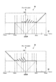
- FIG. 9 shows an operation example of the rotation speed command signal creating unit 36 of the upper control microcomputer 30.
- the rotation speed command signal creation unit 36 creates the rotation speed command signal 21 from the speed command 32 and the direction command signal 22.
- the rotation speed command signal 21 is a PWM signal, and once the duty ratio is determined, the PWM signal can be easily created by the prior art. Therefore, in FIG. 9, only the method of determining the duty ratio of the rotation speed command signal 21 will be described.
- the upper side of FIG. 9 is a graph for determining the duty ratio of the rotation speed command signal 21 when the direction command signal 22 is "1" (normal rotation).
- the lower side of FIG. 9 is a graph for determining the duty ratio of the rotation speed command signal 21 when the direction command signal 22 is “0” (inverted).
- the speed command 32 in the reverse direction is represented by a minus sign.
- the upper control microcomputer 30 stores the relationship between the speed command 32 shown in the upper side of FIG. 9 and the lower side of FIG. 9 and the duty ratio of the PWM signal.
- the duty ratio Dspd may be any value in this region on the lower side of FIG.
- the duty ratio at inversion of the rotation speed command signal 21 is simply set to 0.
- the motor driver 20 cannot operate with the conventional design. Therefore, in the present embodiment, in order to realize the low-speed operation of the motor 10 (-Smin or more and less than Smin), the input of the forward rotation command and the reverse rotation command is alternately repeated for the motor driver 20 in the corresponding low speed range.
- the duty ratio of the rotation number command signal 21 is determined according to the upper side of FIG. 9, and when the direction command signal 22 is "0" (reverse rotation), the duty ratio is determined according to the lower side of FIG.
- the duty ratio of the rotation speed command signal 21 is determined.
- the duty ratio of the direction command signal 22 was the same on both the upper side of FIG. 9 and the lower side of FIG. 9, and was set to Ds_low. From FIG. 5, the duty ratio Ds_low of the rotation speed command signal 21 during low-speed operation can be freely set to be Ds_min or more and 100 (%) or less.
- a large duty ratio Ds_low is preferable so that a large torque can be expected to be generated, and from the viewpoint of power saving, a small value is preferable to control with a small current. This value is determined by the system specifications such as load condition and required power consumption.
- the duty ratio Dspd can be any value in this region on the upper side of FIG. good.
- the duty ratio at the time of normal rotation of the rotation speed command signal 21 is simply set to 0.
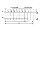
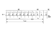
- FIG. 10 is a waveform diagram showing the relationship between the rotation speed command signal 21 and the direction command signal 22 when the rotation speed command signal 21 is determined as shown in FIG.
- numerical numbers (0) to (9) are assigned to the switching timing of the direction command signal 22.
- the switching of the direction command signal 22 is generated at the position (7), and seven pulses are included as the rotation speed command signal 21 in the normal rotation signal generation period Tp in the command unit time Tunit.
- the pulse of the rotation speed command signal 21 included in the normal rotation signal generation period Tp is referred to as a “normal rotation pulse”.
- three pulses are included as the rotation speed command signal 21 in the inversion signal generation period Tn.
- the pulse of the rotation speed command signal 21 included in the inverting signal generation period Tn is referred to as an “inverting pulse”.
- the duty ratio is Ds_low for both the forward rotation pulse and the inversion pulse.
- the ratio of the motor rotation speed command value to the maximum motor rotation speed is set to R, and when the target rotation speed (target speed) is Smin or more, the duty ratio of the rotation speed command signal 21 is set to be equal to R.
- the one-command unit average motor speed ⁇ avr Smax ⁇ (np ⁇ Ds_low ⁇ nn ⁇ Ds_low) / N.
- Ds_low be the minimum duty ratio Ds_min that can be realized by the motor driver 20.
- the motor rotation speed when the duty ratio Ds_min is applied is Smin, so that the rotation speed is 0.4 ⁇ Smax ⁇ Ds_low according to the rotation speed command signal 21 shown in FIG. Since Smax ⁇ Ds_low is the minimum rotation speed Smin that can be realized by the motor driver 20, as a result, rotation at 0.4 ⁇ Smin, which is lower than Smin, can be expected.
- FIG. 11 shows the relationship between the speed command 32 and the average motor speed ⁇ avr per command unit.
- Ds_low Ds_min is set as described above and the duty ratios of the forward pulse and the reverse pulse are equalized, the average motor speed ⁇ avr per command unit has a stepped characteristic with respect to the speed command 32 as shown in FIG. .. Therefore, the motor 10 can operate in a region of less than the minimum rotation speed Smin set in the motor driver IC.
- FIG. 12 is a timing chart showing an example of motor operation when the command unit time Tunit is relatively long.
- the horizontal axis is time, and represents the rotation speed command signal 21, the direction command signal 22, the speed command 71 recognized inside the motor driver 20, and the actual speed 72 of the motor 10 in order from the top.
- the speed command 71 recognized inside the motor driver 20 determines the rotation speed from the duty ratio of the rotation speed command signal 21 and the rotation direction from the direction command signal 22, and operates according to the speed command 71 recognized inside the motor driver 20. Therefore, torque in the forward rotation direction is generated during the period Tp at which the forward rotation pulse is input, and torque in the reverse rotation direction is generated during the period Tn at which the reverse rotation pulse is input. Since the actual speed appears as a primary delay in torque, the shape is as shown at the bottom of FIG.
- the rotation direction of the actual speed 72 alternately repeats forward rotation and reverse rotation in response to the speed command 71 recognized inside the motor driver 20.
- the actual rotation direction repeats forward rotation and reverse rotation
- an impact sound due to the backlash of the mechanical system is generated, which induces adverse effects such as vehicle body vibration and noise.
- the life is shortened due to the impact load. Therefore, even if the speed command 71 recognized inside the motor driver 20 repeats forward rotation / reverse rotation, the rotation direction of the actual speed 72 can maintain the current rotation direction (forward rotation / reverse rotation) during the period of the command unit time Tunit. preferable.
- FIG. 13 shows the conditions for maintaining the actual rotation direction during the command unit time period.
- the upper part of FIG. 13 shows the case where the duty ratio of the speed command 71 recognized inside the motor driver 20 is 90%.
- the middle part of FIG. 13 shows the case where the duty ratio of the speed command 71 recognized inside the motor driver 20 is 70%.
- the lower part of FIG. 13 shows the case where the duty ratio of the speed command 71 recognized inside the motor driver 20 is 50%.
- a case where the rotation direction of the actual speed 72 maintains the normal rotation will be described as an example.
- the duty ratio of the speed command 71 (broken line) recognized inside the motor driver 20 decreases from 90% to 50%, the fluctuation range of the actual speed 72 (solid line) increases.
- the duty ratio of the speed command 71 is less than 50%, the average motor speed ⁇ avr per command unit becomes negative (inverted). Therefore, the necessary condition for the required actual speed 72 to maintain normal rotation is that the motor 10 maintains normal rotation (does not reverse) when the duty ratio of the speed command 71 recognized inside the motor driver 20 is 50%. That is.
- the duty ratio of the speed command 71 such as 40% or 30% is set to less than 50%.
- the shape of the waveform representing the actual speed 72 is determined by the mechanical time constant and the electrical time constant of the motor 10.
- the shape of the actual velocity 72 is mainly a first-order lag shape determined by the mechanical time constant ⁇ mech of the motor 10.
- the motor control device (motor control device 100) according to the first embodiment supplies a PWM signal to the motor driver (motor driver 10) that drives the motor to control the rotation of the motor. ..
- the motor control device uses a predetermined number of PWM signal pulses (command unit division number N) as a command unit, and includes a forward rotation signal generation period (Tp) and an inverting signal generation period (Tn) in the command unit, and is a forward rotation signal.
- Forward rotation number command (forward rotation pulse) in the same direction as the rotation direction of the current motor rotation shaft (motor shaft 11) during the generation period, and reversal in the direction opposite to the rotation direction of the current motor rotation shaft during the inversion signal generation period.
- a motor control command creating device (upper control microcomputer 30) that outputs a rotation speed command (reversal pulse) to a motor driver according to a target rotation speed (speed command 32).
- a rotation speed command reverse pulse
- speed command 32 a target rotation speed
- the normal rotation signal generation period and the reverse rotation signal generation period are included in the command unit of the predetermined number of pulses of pulse width modulation.
- the motor control device can send a rotation number command signal for switching between forward rotation and reverse rotation within the command unit (predetermined number of pulses) of the PWM signal to the motor driver.
- the motor speed is adjusted according to the length of the normal rotation signal generation period (number of forward rotation pulses) and the length of the reverse rotation signal generation period (number of reverse rotation pulses).
- the motor control device it is possible to realize the operation of the motor at the limit rotation speed (set minimum rotation speed) or less of the motor driver by using the motor driver having a restriction on the minimum rotation speed. can. In addition, it is possible to meet drive requirements from extremely low speed to high speed without using an expensive servo motor.
- the target rotation speed (speed command 32) of the motor control command creation device is the minimum setting of the motor driver (motor driver 10).
- the rotation of the motor is controlled by the PWM signal (rotation speed command signal 21, direction command signal 22).
- the PWM control similar to that of a general motor driver is performed, so that the load on development can be reduced. ..
- the operation of the motor can be controlled at the set minimum rotation speed or less by carrying out the PWM control of the present invention described above.
- the cycle T (command unit time Tunit) of the command unit is T ⁇ -2 ⁇ ln (0. It is desirable to have the relationship of 5).
- the motor driver (motor driver 20) that receives the PWM signal from the motor control command creation device (upper control microcomputer 30) maintains the current rotation direction of the motor rotation shaft and drives the motor at the set minimum rotation speed or less. Can be made to. Therefore, it is possible to prevent the motor speed itself (actual rotation direction) from repeating forward rotation and reverse rotation within a short time, and as a result, it is possible to extend the life of the motor and reduce vibration noise.
- the motor control command creation device (forward / reverse pulse number setting unit 33 of the upper control microcomputer 30) is based on the target rotation speed (speed command 32). , The number of pulses of the forward rotation number command (number of normal rotation pulses np) and the number of pulses of the reverse rotation number command (number of reverse rotation pulses nn) are calculated. Based on the number of forward rotation pulses and the number of reverse rotation pulses, the forward rotation signal generation period (Tp) and the inversion signal generation period (Tn) according to the speed command are set.
- the forward rotation pulse and the inverting pulse are output to the motor driver within the command unit, and the operation of the motor is controlled below the set minimum rotation speed of the motor driver. Will be done.
- the motor control command creation device (upper control microcomputer 30) has a pulse number (normal rotation pulse number np) and a reverse rotation number of the forward rotation number command. According to the switching timing based on the number of command pulses (number of inverting pulses nn), pulse width modulation with the normal rotation signal generation period (Tp) and inverting signal generation period (Tn) as the cycle (command unit time Tunit) in the above command unit.
- the direction command creation unit (direction command creation unit 35) that outputs as the direction command signal (direction command signal 22), the forward rotation number command and the reverse rotation number command, and the pulse width modulation rotation number command signal (rotation number command). It is provided with a rotation number command signal creating unit (rotation number command signal creating unit 36) to be output as a signal 21).
- the direction command creating unit and the rotation speed command signal creating unit by providing the direction command creating unit and the rotation speed command signal creating unit, the direction command signal for pulse width modulation and the rotation speed for pulse width modulation according to the speed command (speed command 32) are provided.
- the command signal is supplied to the motor driver.
- FIG. 9 an example in which the duty ratios of the forward rotation pulse and the reverse rotation pulse are equalized is shown, but FIG. 14 shows the normal rotation pulse according to the speed command 32. An example in which the duty ratio of the inverting pulse is changed is shown.
- FIG. 14 shows an example in which the duty ratio of the forward rotation pulse and the reverse rotation pulse of the rotation speed command signal 21 output by the rotation speed command signal creation unit 36 is changed according to the speed command 32.
- a method of changing the duty ratio of the forward rotation pulse and the reverse rotation pulse according to the speed command 32 will be described.
- the upper side of FIG. 14 is a graph for determining the duty ratio of the rotation speed command signal 21 when the direction command signal 22 is "1" (normal rotation).
- the lower side of FIG. 14 is a graph for determining the duty ratio of the rotation speed command signal 21 when the direction command signal 22 is “0” (inverted).
- a stepped actual speed (1 command unit average motor speed ⁇ avr) is obtained for the speed command 32, but the control of FIG. 14 is linear with respect to the speed command 32.
- the duty ratio is set linearly (relationship represented by a linear expression) at each stage in which the speed command 32 is divided at intervals of 2 ⁇ Smin / N. Moreover, the slope of the straight line is adjusted to be different at each stage.
- the duty ratio of the forward pulse is Dsp
- the duty ratio of the reverse pulse is Dsn.
- the duty ratio of the inverting pulse is Ds_min from the lower side of FIG.
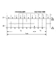
- FIG. 15 is a waveform diagram showing the relationship between the rotation speed command signal 21 and the direction command signal 22 when the rotation speed command signal 21 is determined as shown in FIG.
- numerical numbers (0) to (9) are assigned to the switching timing of the direction command signal 22.
- the switching of the direction command signal 22 occurs at the position (7), and includes seven forward rotation pulses and three reverse rotation pulses in the command unit time Tunit.
- the rotation speed command signal 21 included between the switching timings (0) and (7) is a forward rotation pulse
- the rotation speed command signal 21 included between the subsequent (7) to (0) is an inverting pulse.
- the duty ratio of the forward rotation pulse and the duty ratio of the reverse rotation pulse are determined from the relationship between the speed command 32 and FIG. 14, and as a result, the duty ratio changes at the switching timings (0) and (7).
- the duty ratio of the forward pulse is larger than the duty ratio of the reverse pulse.
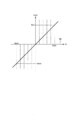
- FIG. 16 shows the relationship between the speed command and the average motor speed ⁇ avr per command unit according to the modified example of the first embodiment.
- the forward / reverse pulse number setting unit 33 is determined as shown in FIG. 7 and the rotation speed command signal creation unit 36 is determined as shown in FIG. 14, as shown in FIG. 16, between -Smin ⁇ ⁇ ⁇ Smin. 1.
- the average motor speed ⁇ avr per command unit can be made linear with respect to the speed command 32.
- the duty ratio of the forward / reverse pulse is relative to the speed command 32 at each stage divided at the interval of 2 ⁇ Smin / N at the time of normal rotation on the upper side of FIG. 14 and the time of reverse rotation on the lower side of FIG. Set to be represented by straight lines (linear) with different slopes.
- the forward rotation speed command (forward rotation pulse) and the reverse rotation speed command (reversal pulse) in the command unit are ,
- the duty ratio of the rotation speed command signal (rotation speed command signal 21) is configured to be different.
- the resolution of the average motor speed ⁇ avr per command unit during low-speed operation can be increased to the resolution achievable by pulse width modulation.
- FIG. 17 is a flowchart showing an example of a procedure of motor control processing by the host control microcomputer 30.
- the host control microcomputer 30 executes this motor control process at predetermined time intervals.
- the setting of FIG. 7 is used as the forward / reverse pulse number setting unit 33
- the setting of FIG. 8 is used as the FRC setting unit 34 and the direction command creation unit 35
- the setting of FIG. 14 is used as the rotation speed command signal creation unit 36.
- step S101 the forward / reverse pulse number setting unit 33 of the host control microcomputer 30 executes the command value acquisition process.
- the target speed command ⁇ cmd has a negative value
- the target rotation direction indicated by the target speed command ⁇ cmd is the inversion direction.
- step S102 the forward / reverse pulse number setting unit 33 executes the low-speed mode determination process.
- the low-speed mode determination process the magnitude relationship between the target rotation speed Scmd and the feasible minimum rotation speed Smin of the motor driver 20 is compared.
- the forward / reverse pulse number setting unit 33 is in a low speed mode (YES in S102) when the target rotation speed Scmd is smaller than the minimum rotation speed Smin, and is normal when the target rotation speed Scmd is the minimum rotation speed Smin or more. It is determined that the mode (NO in S102).
- step S102 when the low speed mode is determined in step S102, the forward / reverse pulse number setting unit 33 executes the previous mode determination process in step S103. If the low-speed mode was executed last time (YES in S103), the process proceeds to the FRC overflow determination process in step S104. On the other hand, in the case of the previous normal mode (NO in S103), the process proceeds to the normal rotation pulse number setting process in step S105.
- the forward / reverse pulse number setting unit 33 determines whether or not there is an overflow interrupt (denoted as “OVF interrupt” in the figure).
- the overflow interrupt is a so-called timer interrupt.
- the forward / reverse pulse number setting unit 33 shifts to the initialization mode and executes the forward rotation pulse number setting process in step S105.
- the rotation direction switching timing detection process in step S107 is executed as the low-speed continuation mode.
- a part or all of the processing of steps S101 to S104 may be executed by another block included in the upper control microcomputer 30, for example, a VTC control unit 31 or a main control unit (not shown).
- the forward / reverse pulse number setting unit 33 executes the forward / reverse pulse number setting process in step S105. That is, the forward / reverse pulse number setting unit 33 sets the forward rotation pulse number np based on the speed command 32 (target speed command ⁇ cmd) as described with reference to FIG. 7.
- step S106 the FRC setting unit 34 executes the FRC setting process.
- FRC setting values FRC_ovf, FRC_chg
- FRC value the FRC count value
- the FRC setting unit 34 performs the rotation direction switching time detection processing in step S107.
- the FRC setting unit 34 compares the FRC value with the FRC_chg obtained in step S106, and if the FRC value is smaller than the FRC_chg (YES in S107), the FRC setting unit 34 shifts to the forward rotation direction duty calculation process in step S108.
- the FRC setting unit 34 outputs a forward / reverse switching signal 38 and shifts to the reverse direction duty calculation process in step S110.
- step S108 the direction command creating unit 35 calculates the forward rotation direction duty Dsp.
- step S109 the direction command creating unit 35 executes the forward rotation direction duty setting process.
- step S110 the direction command creating unit 35 calculates the reverse direction duty Dsn.
- step S111 the direction command creating unit 35 executes the reverse direction duty setting process.
- the process proceeds to the normal mode command signal creation process in step S112. That is, the host control microcomputer 30 creates a command signal for operating the motor driver 20 as usual without performing the motor control of the present invention.
- the direction command creating unit 35 and the rotation speed command signal creating unit 36 have a period in which forward rotation torque is generated (forward rotation signal generation period Tp) and a period in which reverse rotation torque is generated (inversion signal generation period Tn), respectively, within the command unit time.
- the rotation speed command signal 21 and the direction command signal 22 are output without switching.
- step S113 the host control microcomputer 30 executes the command signal output process. That is, the rotation speed command signal creating unit 36 and the direction command creating unit 35 are set by the forward rotation direction duty setting process (S109), the reverse direction duty setting process (S111), or the normal mode command signal creation process (S112), respectively.
- the rotation speed command signal 21 and the direction command signal 22 are output from the duty ratio Ds and the rotation direction Dir.
- the motor control method of the present invention is particularly applied to an application that realizes a large speed fluctuation range from high speed to low speed and high responsiveness at low cost, and the motor is a brushless DC motor.
- a variable valve timing control device for controlling the opening / closing timing of at least one of an intake valve and an exhaust valve provided in an internal combustion engine by using a motor is assumed.
- the present invention can also be applied to an active vibration damping device for an engine, a Stirling engine, and the like.
- FIG. 18 is a waveform diagram showing an example of the rotation speed command signal 21 according to the second embodiment of the present invention. With reference to FIG. 18, another method of generating the rotation speed command signal 21 according to the second embodiment will be described in detail.
- low-speed operation of the motor 10 is realized by alternately repeating torques in the forward rotation direction and the reverse rotation direction within a short time at a rotation speed equal to or lower than the driveable limit of the motor driver 20.
- a so-called reverse braking operation in which the connection of the armature windings of the motor is changed to the reverse connection to rapidly decelerate
- this method has good controllability, large currents tend to flow depending on the application, and it may be necessary to strengthen heat resistance measures or take measures against large currents.
- the relaxation pulse 73 into the PWM signal immediately before the switching of the direction command signal 22 (switching timing (7)).
- the relaxation pulse 73 temporarily lowers the current value to near 0 by reducing the duty ratio of the rotation speed command signal 21 to less than Ds_min.
- the rotation speed command signal 21 outputs a predetermined inverting pulse. This makes it possible to prevent the motor current from jumping at the moment when the torque in the forward rotation direction and the torque in the reverse rotation direction are switched.
- the replacement timing of the relaxation pulse 73 may be any timing as long as it switches between normal rotation and reverse rotation. Therefore, it is preferable to replace the rotation speed command signal 21 with a relaxation pulse immediately before the rise, immediately after the rise, immediately before the fall, immediately after the fall, or a combination thereof of the direction command signal 22.
- the command unit division number N is as small as 10, and the period Tp indicating normal rotation is longer than the period Tn indicating inversion. Therefore, the positive immediately before the fall of the direction command signal 22.
- the rolling pulse is replaced with a relaxation pulse 73.
- the motor control command creation device (upper control microcomputer 30) has a forward rotation signal generation period (Tp) and an inverting signal generation period (Tn). ) Immediately before or immediately after the switching, the pulse of the rotation number command signal (rotation number command signal 21) is replaced with a pulse (relaxation pulse 73) having a command value smaller than the command value of the previous pulse. It is configured.
- the difference between the command values of the rotation speed command signals can be reduced before and after switching between the normal rotation signal generation period and the reverse rotation signal generation period. Therefore, it is possible to suppress a sudden change in the motor current when switching the rotation direction command (torque in the forward rotation direction and the reverse rotation direction) within the command unit, reduce the motor current, and simplify the cooling system. Further, the circuit cost of the motor control device and the cooling system cost can be reduced.
- the first and second embodiments have been described above as a configuration for realizing the present invention by using the rotation speed command signal 21 and the direction command signal 22 as command signals to the motor driver.
- the present invention is not limited to this.
- the present invention can be similarly implemented even in a system that uses a signal that combines a rotation speed command and a rotation direction command as a command signal to the motor driver.
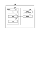
- FIG. 19 is a block diagram showing a configuration example of hardware of a higher-level control microcomputer included in the motor control device according to the third embodiment of the present invention.
- the host control microcomputer 30A shown in FIG. 19 replaces the rotation speed command signal creating unit 36 of FIG. 2 with the rotation speed command signal creating unit 36A that creates a combined command signal that combines the rotation speed command and the rotation direction command. To prepare for.
- the rotation speed command signal creating unit 36A is an example of the combined command signal creating unit.
- the upper control microcomputer 30A will be described by focusing on a portion different from that of the upper control microcomputer 30 in FIG.
- the rotation speed command signal creation unit 36A creates a composite command signal 81 by combining the rotation speed command and the rotation direction command based on the speed command 32 and the direction command signal 22, and uses the created composite command signal 81 as a motor. Output to driver 20A. That is, the rotation number command signal creation unit 36A reverses the rotation direction command including the information of the forward rotation signal generation period Tp and the reverse rotation signal generation period Tn, the normal rotation rotation speed command (forward rotation pulse), and the reverse rotation number command (forward rotation pulse) in the command unit. Outputs a pulse width modulation composite command signal 81 that is a composite of a rotation speed command (inverted pulse).
- the rotation speed command signal creating unit 36A has a forward rotation signal generation period Tp based on the calculated rotation direction command and speed command 32, based on the correspondence between the duty ratio and the motor speed (motor rotation speed) shown in FIG.
- the duty ratio (operating point 82) and the duty ratio at the time of the inversion command (operating point 83) are set.
- the rotation speed command signal creation unit 36A creates a composite command signal 81 from the set operating point 82, operating point 83, and rotation direction command (forward rotation signal generation period Tp, reverse rotation signal generation period Tn), and the motor.
- the motor driver 20A is configured to interpret the composite command signal 81 and generate a gate signal 19 to be supplied to the gate driver 17.
- the host control microcomputer 30A has a configuration in which the rotation speed command signal creation unit 36A creates a composite command signal, but the combined functions of the rotation speed command signal creation unit 36 and the direction command creation unit 35 are included in one block.
- the command signal creation unit may be configured to create a composite command signal.
- the combined command signal generation unit Based on the speed command 32, the forward / reverse switching signal 38, and the reverse / forward switching signal 39, the combined command signal generation unit has a forward rotation signal generation period Tp and a duty ratio (operating point 82), and an inverting signal generation period Tn and a duty. The ratio (operating point 83) is determined, and the composite command signal 81 is created.
- FIG. 20 shows an example of the relationship between the PWM duty ratio and the motor speed (motor rotation speed) as an example of the characteristics of the motor driver 20A.
- the motor driver 20A having the characteristics shown in FIG. 20 is operated at a low speed by the motor control method according to the present invention will be described.
- FIG. 20 shows that the PWM duty ratio is divided into a region corresponding to the forward rotation side characteristic and a region corresponding to the reverse rotation side characteristic.
- the rotation speed command signal 21 and the direction command signal 22 in the first and second embodiments can be combined into one combined command signal 81 of the rotation speed and the rotation direction.
- the host control microcomputer 30A stores the correspondence between the duty ratio of the motor driver 20 and the motor speed (motor rotation speed) shown in FIG. 20.
- Smax_p is the maximum rotation speed of the forward rotation side motor.
- Smin_p is the minimum rotation speed of the forward rotation side motor.
- Smax_n (sign is minus) is the maximum rotation speed of the inverting motor.
- Smin_n (sign is minus) is the minimum rotation speed of the inverting motor.
- Da_min is the minimum operating duty ratio.
- Da_n is the inversion operation boundary duty ratio.
- Da_p is the forward rotation operation boundary duty ratio.
- Da_max is the maximum operating duty ratio. The motor speed is judged to be 0 in the region from the duty ratio Da_n to Da_p.
- the forward rotation operation is commanded in the range of motor speed Smin_p to Smax_p.
- the reason why the motor is not operated in the region below the motor speed Smin_p is that in a system where the rotation angle sensor 12 is not costly, the speed is within the time that can be used as speed feedback in the low speed range as described in FIG. Due to the difficulty of obtaining.
- the inversion operation is commanded in the range of motor speed -Smax_n to -Smin_n.
- the reason why the motor 10 is not operated in the region of motor speed-Smin_n to 0 is the same as that at the time of normal rotation. Further, the reason why the motor 10 is not operated in the region where the duty ratio is from 0 to Da_min and from Da_max to 100 [%] is due to the reason (noise) shown in FIG.
- the operating point 82 is an example of the operating point at the time of the forward rotation command
- the operating point 83 is an example of the operating point at the time of the reverse rotation command.
- the waveforms of the forward pulse and the reverse pulse of the composite command signal 81 are determined by the positions of the operating point 82 and the operating point 83.
- FIG. 20 shows an example in which the normal rotation side characteristic and the reverse rotation side characteristic of the motor 10 are different for generalization, the normal rotation side characteristic and the reverse rotation side characteristic may be the same.
- FIG. 21 shows an operation example of the rotation speed command signal creating unit 36A of the upper control microcomputer 30A.
- the rotation speed command signal creation unit 36A creates the composite command signal 81 from the speed command 32 and the direction command signal 22.
- the composite command signal 81 is a PWM signal.
- the upper side of FIG. 21 is a graph for determining the duty ratio of the composite command signal 81 when the direction command signal 22 is “1” (normal rotation).
- the lower side of FIG. 21 is a graph for determining the duty ratio of the composite command signal 81 when the direction command signal 22 is “0” (inverted).
- the forward rotation and the inversion of the rotation speed command signal 21 have symmetry (if the motor rotation speed is the same, the characteristics are the same regardless of whether the rotation speed is forward rotation or inversion).
- the composite command signal 81 has different characteristics between forward rotation and reverse rotation. For example, in a motor that has a hardware advance function, the characteristics of the motor driver change between forward rotation and reverse rotation, so the characteristics of the motor driver also change between forward rotation and reverse rotation.
- the duty ratio of the composite command signal 81 in the low speed region (-Smin_n ⁇ ⁇ ⁇ Smin_p) of the motor 10, is set to Da_p in normal rotation, and the composite command signal 81 (reverse) is set in inversion.
- the duty ratio of the pulse) is set to Da_n. It should be noted that even by the method of setting the duty ratio of the rotation speed command signal 21 shown in FIGS. 9 and 14, the asymmetric motor can be driven with a small modification (for example, the duty ratio is changed between normal rotation and reverse rotation). It is possible.
- FIG. 22 is a waveform diagram showing an example of a composite command signal 81 when an internal combustion engine (for example, an engine 51) is operated at a low speed in the setting of FIG. 20 (FIG. 21).
- the duty ratio of the forward pulse is larger than the duty ratio of the reverse pulse.
- the motor driver 20A can discriminate between the forward rotation signal generation period Tp and the reverse rotation signal generation period Tn based on the difference in the duty ratio between the operating point 82 and the operating point 83 of the composite command signal 81.
- the motor control command creation device (upper control microcomputer 30A) has a forward rotation signal generation period (Tp) and an inverting signal generation period (Tn) within the command unit.
- a compound command that outputs a pulse width modulation compound command signal (composite command signal 81) that combines a rotation direction command that specifies A signal creation unit (rotation number command signal creation unit 36A) is provided, and the waveform differs between the forward rotation number command and the reverse rotation number command in the combined command signal.
- the duty ratio of the pulse of the forward rotation speed command (normal rotation pulse) is different from the duty ratio of the pulse of the reverse rotation speed command (reversal pulse).
- the waveforms of the forward rotation speed command and the reverse rotation speed command are different and included in one composite command signal, and the composite command signal is supplied to the motor driver. do. Since the motor driver recognizes the forward rotation speed command and the reverse rotation speed command from the difference in waveform and drives the motor, the operation of the motor can be controlled by one compound command signal. By using such a composite command signal, the number of wirings and the chip size of the host control microcomputer and the motor driver can be reduced, and the weight and cost can be reduced.
- the effect of the first embodiment is the same. The effect of is obtained.
- FIG. 22 shows an example in which the duty ratio of the forward rotation pulse is larger than the duty ratio of the inverting pulse, but it does not exclude the case where the duty ratio of the forward rotation pulse is smaller than the duty ratio of the inverting pulse.
- FIG. 23 is a waveform diagram showing an example of a composite command signal when the internal combustion engine (engine 51) is operated at a low speed by a setting different from that of FIG. 20.
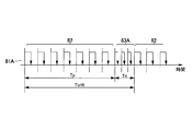
- the composite command signal 81A when the correspondence between the duty ratio and the motor rotation speed different from that in FIG. 20 is used with reference to FIG. 23 will be described.
- the motor driver 20A determines that the forward rotation signal generation period Tp is when the PWM cycle of the composite command signal 81A is longer than the predetermined cycle (the PWM frequency is lower than the predetermined frequency). Further, when the PWM cycle of the composite command signal 81A is shorter than the predetermined cycle (the PWM frequency is higher than the predetermined frequency), it is determined that the inverted signal generation period Tn. That is, the duty ratio on the horizontal axis in FIG. 20 can be replaced with the PWM cycle.
- the waveform of the composite command signal (composite command signal 81A) is different from the waveform of the composite command signal 81 used in the third embodiment. That is, in the present embodiment, the frequency of the pulse train of the forward rotation speed command (normal rotation pulse) is different from the frequency of the reverse rotation speed command (reverse pulse) in the compound command signal.
- the same effect as that of the third embodiment can be obtained by making the frequencies of the forward rotation speed command and the reverse rotation speed command different.
- the frequency of the forward rotation pulse train is lower than the frequency of the reverse rotation pulse train is shown, but the case where the frequency of the forward rotation pulse train is higher than the frequency of the reverse rotation pulse train is not excluded.
- the motor control using the above-mentioned upper control microcomputer 30 can be executed by hardware or by software.
- FIG. 24 is a block diagram showing a hardware configuration example when the host control microcomputer 30 is configured by the computer 300.
- the computer 300 is an example of hardware used as a computer that can operate as a higher-level control microcomputer 30.
- An electronic control unit (ECU) can be used as the upper control microcomputer 30.
- the computer 300 includes a control unit 310, a storage unit 320, and an input / output interface 330 connected to each other via a system bus.
- the control unit 310 is composed of a CPU (central processing unit) 311, a ROM (ReadOnlyMemory) 312, and a RAM (RandomAccessMemory) 313.
- the CPU 311 reads the control program stored in the ROM 312 into the RAM 313 and executes it, each function according to the present embodiment is realized.
- the control unit 310 includes a VTC control unit 31, a forward / reverse pulse number setting unit 33, an FRC setting unit 34, a direction command creation unit 35, a rotation speed command signal creation unit 36, 36A, and a composite command signal creation unit (not shown).
- a CPU is used as the arithmetic processing unit, another processor such as an MPU (microprocessing unit) may be used.
- the storage unit 320 is an auxiliary storage device composed of a semiconductor memory or the like, and records a program for operating the computer 300 in addition to an OS (Operating System) and various parameters.
- OS Operating System
- the storage unit 320 stores information regarding correspondence relationships and settings shown in FIGS. 7 to 9, 14, 20, and 21.
- the input / output interface 330 is an interface for communicating signals and data with each sensor and each actuator.
- the input / output interface 330 may also serve as an A / D (Analog / digital) converter and / or a D / A converter (not shown) that processes the input / output signals of each sensor.
- each of the above-described embodiments describes the configuration of the motor control device in detail and concretely in order to explain the present invention in an easy-to-understand manner, and is not necessarily limited to those including all the components described above. Further, it is possible to replace a part of the configuration of one embodiment with a component of another embodiment. It is also possible to add components of another embodiment to the configuration of one embodiment. It is also possible to add, replace, or delete other components for a part of the configuration of each embodiment.
- each configuration, function, processing unit, etc. of each of the above-described embodiments may be realized by hardware, for example, by designing a part or all of them by an integrated circuit.
- FPGA Field Programmable Gate Array
- ASIC Application Specific Integrated Circuit
- a plurality of processes may be executed in parallel or the processing order may be changed as long as the processing results are not affected.
Landscapes
- Engineering & Computer Science (AREA)
- Power Engineering (AREA)
- Control Of Motors That Do Not Use Commutators (AREA)
- Control Of Ac Motors In General (AREA)
Abstract
本発明の課題は、モータドライバの設定最低回転数以下でモータの回転を制御することである。 本発明の一態様のモータ制御装置は、PWM信号の所定パルス数を指令単位Tunitとし、指令単位Tunit内に正転信号発生期間Tpと反転信号発生期間Tnを含み、正転信号発生期間Tpにおいて現在のモータ回転軸の回転方向と同じ方向の正転回転数指令、反転信号発生期間Tnにおいて現在のモータ回転軸の回転方向とは反対方向の反転回転数指令を、目標回転数に応じてモータドライバに出力するモータ制御指令作成装置(上位制御マイコン30)を備える。
Description
本発明は、モータ制御装置及びモータ制御方法に関する。
内燃機関エンジンは、最適な燃焼を実現することで燃費低減、排気のクリーン化が求められている。そのための一部として、内燃機関エンジン補機の電動化が進められている。油圧や機構によって実現していた部分を電動化することで、制御応答性の向上や、特に摩擦などの機械的損失の低減が期待できる。これまで、ポンプや冷却ファン、パワーステアリングなどについて電動化が進展している。さらに、可変バルブタイミング制御装置のように、エンジン燃焼制御にかかわる部分への電動化の適用が増えている。
自動車では、バッテリを電源として使用するために電動駆動源として直流モータが用いられる。従来、ブラシ整流子を用いる直流整流子モータが主流であったが、近年のパワーエレクトロニクスの発展に伴い、ブラシレス直流モータが普及しつつある。ブラシレス直流モータは、ホールICやエンコーダといった回転角センサによって磁極位置を検出し、検出した回転角に基づきモータコイルに印加する電圧を制御する。これによりブラシが不要になるために、ブラシレス直流モータは小型化、長寿命化に有利である。
従来は、ブラシレス直流モータの駆動制御を行うために、ブラシ付き直流モータの駆動回路と比較すると高価なマイクロコンピュータ(以下「マイコン」と略記する)を駆動回路として用いる必要があった。しかし、ブラシレス直流モータが普及するに従い、駆動制御を行う専用モータドライバICが安価で入手可能となってきており、システムコストも下がっている。
例えば、特許文献1に、アクチュエータへの動作指示のための制御信号を適切に設定することによってバルブタイミング制御の安定性を高める技術が開示されている。この特許文献1には、「制御装置は、作動方向および制御モードの想定される複数の組合せごとに予め決められた所定値に従って、動作指示における作動方向および選択された制御モードの組合せに応じてパルス波状の動作指示信号のデューティ比を設定する」ことが記載されている。
ところで、可変バルブタイミング制御装置は、モータの回転軸に取り付けられたカムがバルブを開閉する回転同期型である。エンジンの回転角に対してカムの回転角が変化しない場合には、モータはエンジンと同期した回転を保持する。エンジンの回転角に対応するモータの回転角を変化させることによって、開弁又は閉弁タイミングを制御することができる。このような構成の可変バルブタイミング制御装置は、急速な開弁又は閉弁タイミングの変化を実現しなければならず、モータが実現しなければならない速度範囲も高速側から速度零付近の低速側まで及ぶ。また、場合によっては、回転方向を反転することも要求される。しかも、これらのモータ制御を安価に実現することが求められる。
安価にモータ制御を実現するための制御部として、前述の安価な専用モータドライバICの採用があげられる。しかし、システムコストを安くするためには、モータ制御に必要不可欠なモータの回転角センサとして高精度のものを使うことができず、分解能の粗いホールICに頼ることが多い。また、安価な専用モータドライバICでは、コスト上昇要因となるCAN(Controller Area Network)やFlexRay(多重通信技術の通信規格)などの通信制御を用いず、パルス列により指令値を送出する単純なPWM(Pulse Width Modulation)通信が採用される。
これらの比較的低価格の構成ではモータの低速動作の制御が困難である。そのため、安価な専用モータドライバICでは、一定回転数(例えば毎分400回転)以下の動作は行わない仕様となっているものが多い。以上のように、安価な可変バルブタイミング制御装置を実現するためには、最低回転数に制約のある安価な専用モータドライバICを用いて、当該ICの限界回転数(設定最低回転数)以下の動作を実現することが課題となっている。特許文献1は、この点について言及していない。
本発明は、上記の状況に鑑みてなされたものであり、最低回転数に制約のあるモータドライバを用いて、当該モータドライバの設定最低回転数以下でモータの動作を実現することを目的とする。
上記課題を解決するために、本発明の一態様のモータ制御装置は、モータを駆動するモータドライバにPWM信号を供給して当該モータの回転を制御するモータ制御装置である。
このモータ制御装置は、PWM信号の所定パルス数を指令単位とし、その指令単位内に正転信号発生期間と反転信号発生期間を含み、正転信号発生期間において現在のモータ回転軸の回転方向と同じ方向の正転回転数指令、反転信号発生期間において現在のモータ回転軸の回転方向とは反対方向の反転回転数指令を、目標回転数に応じてモータドライバに出力するモータ制御指令作成装置を備える。
このモータ制御装置は、PWM信号の所定パルス数を指令単位とし、その指令単位内に正転信号発生期間と反転信号発生期間を含み、正転信号発生期間において現在のモータ回転軸の回転方向と同じ方向の正転回転数指令、反転信号発生期間において現在のモータ回転軸の回転方向とは反対方向の反転回転数指令を、目標回転数に応じてモータドライバに出力するモータ制御指令作成装置を備える。
本発明の少なくとも一態様によれば、最低回転数に制約のあるモータドライバを用いて、当該モータドライバの設定最低回転数以下でモータの動作を実現することができる。
上記した以外の課題、構成及び効果は、以下の実施形態の説明により明らかにされる。
上記した以外の課題、構成及び効果は、以下の実施形態の説明により明らかにされる。
以下、本発明を実施するための形態の例について、添付図面を参照して説明する。本明細書及び添付図面において実質的に同一の機能又は構成を有する構成要素については、同一の符号を付して重複する説明を省略する。
<第1の実施形態>[モータ制御装置と内燃機関の概要] まず、本発明の第1の実施形態に係るモータ制御装置について図1~図3を参照して説明する。図1は、本発明の第1の実施形態に係るモータ制御装置の全体構成例を示す。図2は、モータ制御装置が備える上位制御マイコンのハードウェアの構成例を示すブロック図である。図3は、可変バルブタイミング制御装置を備えた内燃機関の構成例を示す概略断面図である。
図1では、三相モータ駆動用のインバータとして本発明の方法により制御される電力変換装置を用いた例について説明する。モータ制御装置100は、電力変換装置14、モータドライバ20、及び上位制御マイコン30を備える。ここで、制御対象となるモータ10は、ブラシレス直流モータである。モータ10は、発生したトルクを伝達するモータシャフト11と連結している。
ブラシレス直流モータは、各巻線に電圧をかけるタイミングを回転角センサ12によって判断する。回転角センサ12としては、アブソリュートエンコーダやレゾルバなどが利用可能であるが、本実施形態ではモータ制御装置100を安価に実現することを考えて、ホールICを用いる。ホールICは、磁束方向の情報をデジタル信号として出力するものである。モータ10の各相の配線13には、電力変換装置14から交流電圧が印加される。電力変換装置14は、複数(例えば6個)のスイッチング素子15を備え、スイッチング素子15をON/OFFさせることにより直流電圧Vdcを交流電圧に変換して配線13に印加される交流電圧を作成する。
直流電流検出器16は、電力変換装置14に流入又は流出する電流を測定する。一般的には、シャント抵抗を接地点AGNDとスイッチング素子15の負極側接続端子の間に挿入し、シャント抵抗の両端電圧を測定することにより電流を検出する。スイッチング素子15は、ゲートドライバ17で作成されるゲート電圧18によってON/OFFされる。ゲートドライバ17は、スイッチング素子15のON/OFFタイミングを決定するゲート信号19を増幅し、スイッチング素子15が動作可能となる電圧及び電流に変換する。モータドライバ20は、上位制御系からの回転数指令信号21及び方向指令信号22に従って、モータ10を動作させるためのゲート信号19を作成する。
本発明においては、モータドライバ20として安価なモータドライバICを使用することを想定する。回転数指令信号21はPWM信号で与えられ、そのデューティ比(周期に対するON信号時間の割合)によって回転数指令の値(例えばrpm)を表す。方向指令信号22は一般にデジタル信号であり、例えば5Vのときを正転指令、0Vのときを反転指令とする。以降の説明では、方向指令信号22がONのときを「1」、OFFのときを「0」と表す。
なお、実際の回転方向に対して正転、反転は設計者が自由に決定できる。ここでは、モータ回転軸に向かって時計回り(CW)を正転、反時計回り(CCW)を反転と定義する。モータドライバ20は、その他入力として回転角センサ信号23や直流電流信号24を利用する。回転角センサ信号23は回転角センサ12の出力であり、直流電流信号24は直流電流検出器16の出力である。
上位制御マイコン30は上位制御系を構成する制御装置であり、モータ10の回転数指令信号21と、方向指令信号22を作成する。図2に示すように、上位制御マイコン30は、エンジン回転数(図示せず)やエンジン温度(図示せず)など、エンジン状態を検知するセンサ信号を入力として、電動VTC(VTC:variable timing camshaft)のモータ速度を規定する速度指令32を生成するVTC制御部31を備える。速度指令32は、回転数指令信号作成部36と正反パルス数設定部33に入力される。本明細書において、モータ速度は回転速度であり、回転数と同義である。回転数は、単位時間当たりの回転数を意味する。
また、上位制御マイコン30は、正反パルス数設定部33、FRC(Free Running Counter)設定部34、方向指令作成部35、及び回転数指令信号作成部36を備える。
正反パルス数設定部33は、VTC制御部31が出力する速度指令32に基づいて、方向指令信号22内の正転信号発生期間及び反転信号発生期間(後述する図10参照)に含有する回転数指令信号21のパルス数を設定し、設定結果をFRC設定部34へ出力する。
FRC設定部34は、回転数指令信号21のパルス数の設定結果に基づいて、正転から反転、及び反転から正転への切り替えタイミングを算出して方向指令作成部35に通知する。
方向指令作成部35は、FRC設定部34から受信した切り替えタイミングの情報から、方向指令信号22を作成してモータドライバ20へ出力する。また、方向指令作成部35は、方向指令信号22を回転数指令信号作成部36にも出力する。
回転数指令信号作成部36は、速度指令32及び方向指令信号22に基づいて、回転数指令信号21を作成してモータドライバ20へ出力する。
FRC設定部34は、回転数指令信号21のパルス数の設定結果に基づいて、正転から反転、及び反転から正転への切り替えタイミングを算出して方向指令作成部35に通知する。
方向指令作成部35は、FRC設定部34から受信した切り替えタイミングの情報から、方向指令信号22を作成してモータドライバ20へ出力する。また、方向指令作成部35は、方向指令信号22を回転数指令信号作成部36にも出力する。
回転数指令信号作成部36は、速度指令32及び方向指令信号22に基づいて、回転数指令信号21を作成してモータドライバ20へ出力する。
上述した正反パルス数設定部33は、速度指令32に基づいて正転パルス数37を設定する。ここで、正転パルス数37は、方向指令信号22が正転方向を表す区間に含まれる回転数指令信号21のパルス数と定義する。FRC設定部34では、正転パルス数37の情報を用いて、方向指令信号22の切り替えタイミングを示す切替信号が生成される。ここで、正反切替信号38は、方向指令信号22が正転から反転に切り替わるタイミングを方向指令作成部35に通知する。また、反正切替信号39は、方向指令信号22が反転から正転に切り替わるタイミングを方向指令作成部35に通知する。正反パルス数設定部33、FRC設定部34、方向指令作成部35、及び回転数指令信号作成部36の詳細な動作については別の図を用いて後述する。
モータ10は、可変バルブタイミング制御装置110(図3参照)に取り付けられる。
図3に示すように、可変バルブタイミング制御装置110は、エンジン51に設けられる。可変バルブタイミング制御装置110は、吸気側電動バルブタイミング制御モータ10a、及び排気側電動バルブタイミング制御モータ10bを備える。
図3に示すように、可変バルブタイミング制御装置110は、エンジン51に設けられる。可変バルブタイミング制御装置110は、吸気側電動バルブタイミング制御モータ10a、及び排気側電動バルブタイミング制御モータ10bを備える。
吸気側カム軸53aは、適切な減速機(図示せず)を介して吸気側電動バルブタイミング制御モータ10aに取り付けられる。また、排気側カム軸53bは、適切な減速機(図示せず)を介して排気側電動バルブタイミング制御モータ10bに取り付けられる。吸気カム54aは、吸気バルブステムエンド55aを押すことにより吸気バルブ56aを開弁する。吸気カム54aが吸気バルブステムエンド55aを押さない位置に回転した時、吸気バルブスプリング57aによって吸気バルブ56aは閉弁する。排気側にあっても同様である。排気カム54bは、排気バルブステムエンド55bを押すことにより排気バルブ56bを開弁する。排気カム54bが排気バルブステムエンド55bを押さない位置に回転した時、排気バルブスプリング57bによって排気バルブ56bは閉弁する。
図3に記載した可変バルブタイミング制御装置110は回転同期型と呼ばれる方式である。吸気側カム軸53a及び排気側カム軸53bは、通常時はクランク軸52と同期して回転するように制御される。なお、4ストローク内燃機関の場合、「同期状態」とは、クランク軸52の回転に対してカム軸が1回転し、かつ開弁開始角度と開弁終了角度が常に同じクランク軸角度となるように制御されていることと定義する。
このような可変バルブタイミング制御装置110では、同期状態から吸気側電動バルブタイミング制御モータ10aの回転数を一瞬速くし、所望の開弁開始角度となったところで再度同期状態に復帰することで、吸気タイミングを早めることができる。これを「進角」と記載する。また、同期状態から吸気側電動バルブタイミング制御モータ10aの回転数を一瞬遅くし、所望の開弁開始角度となったところで再度同期状態に復帰することで、吸気タイミングを遅くすることができる。これを「遅角」と記載する。排気弁側についても全く同様に制御できる。
以降、本実施形態に係るモータ制御について説明するが、使用する用語及び記号について事前に説明する。
「ωcmd」は、上位制御マイコン30が出力する目標速度指令である。なお、この情報は回転方向の情報を含み、例えばωcmdが正のとき正転、ωcmdが負のとき反転(逆転)と定義する。
「Dir_cmd」は、上位制御マイコン30が出力する回転方向指令であり、例えばωcmdが正のとき1、ωcmdが負のとき0と定義する。上記のように定義した場合、Dir_cmd=0.5(1+sgn(ωcmd))の関係式で表される。「sgn」は引数が正のとき1を、負のときは-1を返す関数である。
「Smax」は、モータドライバ20が想定するモータ回転数の最大値である。ここでは、モータ回転数はモータ速度の絶対値と定義する。モータ最高速度をωmaxとすると、モータ最高回転数はabs(ωmax)である。「abs」は引数の絶対値を返す関数である。本実施形態ではブラシレス直流モータを想定しており、正転と反転とで特性の違いは無いものとする。「Smin」は、通常のPWM制御でモータドライバ20が実現できるモータ回転数の最低値(設定最低回転数)である。
「Rmin」は最低回転数比であり、Smin/Smaxと定義する。同様に「Rcmd」は目標回転数比であり、Scmd/Smaxと定義する。ここで、「Scmd」はabs(ωcmd)である。回転数指令信号21のデューティ比Dspdは、目標回転数比Rcmdによって定義される。以降の説明では簡単のためDspd=Rcmdとする。
本発明は、回転方向指令を正転から反転に切り替えても、慣性によりモータの回転がすぐには反転しないことを利用してモータ速度を制御する。そこで、本発明は、モータ10を極低速で駆動時に、後述する図8及び図10に示すように、一定期間(指令単位時間Tunit)に方向指令信号22のON/OFFを切り替えることを特徴とする。そのため、極低速での駆動時に、方向指令信号22も回転数指令信号21と同様にPWM信号として出力される。方向指令信号22のPWM周期は、回転数指令信号21のPWM周期よりも長くなる。
指令単位の中には複数の回転数指令信号21のパルスが含まれ、その個数を指令単位分割数Nと定義する。1指令単位中の方向指令信号22が「正転」を示す期間を「Tp」とし、期間Tpに含まれる回転数指令信号21のパルス数を正転パルス数npとする。同様に、1指令単位中の方向指令信号22が「反転」を示す期間を「Tn」し、期間Tnに含まれる回転数指令信号21のパルス数を反転パルス数nnと定義する。これらには、N=np+nnの関係が成立する。
Tunitを指令単位時間、Tpを正転信号発生期間、Tnを反転信号発生期間と呼称する。方向指令信号22がPWM動作しているときのデューティ比Ddirは、Ddir=Tp/Tunitと表わされる。また、回転数指令信号21については、PWM周期を「Ts」、ON期間を「Ts_on」、OFF期間を「Ts_off」と記載する。回転数指令信号21や方向指令信号22のON、OFFの決め方には恣意性があるが、ここでは簡単のため、“1”をON、“0”をOFFとする。回転数指令信号21のデューティ比Dspdは、Ts_on/Ts、又は(1-Ts_off)/Tsと書ける。
モータドライバ20に対して制御指令信号を送るための通信手段としては、CAN、SPI(Serial Peripheral Interface)などの通信プロトコルやアナログ信号など様々な種類がある。安価なモータドライバICによく用いられるのはPWMである。PWMは、ONとOFFの占める時間割合によって制御指令値を送る。PWM通信は、GND(グランド)を除けば1本の配線で通信可能であること、他通信規格と比較して伝送回路が単純であること、デジタル信号なのでノイズ耐性が高いことなど様々な利点を有するために広く用いられている。
[一般的なPWM信号を用いたモータ制御] 次に、一般的なPWM信号を用いたモータ制御の課題について図4を参照して説明する。
図4は、一般的なPWM信号を用いたモータ制御の課題を説明するための波形図である。図4では、PWMを利用して回転数指令信号21を送出する例を示しており、上から下に向かって回転数指令が小さい場合を示している。回転数指令が十分大きい場合には、PWM周期に対するON期間Ts_onが大きく、ノイズが混入した場合でも誤動作は少ない。
しかしながら、回転数指令が小さくなるに従い、ON期間Ts_onが小さくなり、パルス幅が細くなっていく。そして、パルス幅が細くなり過ぎると、パルスがノイズと区別できなくなる。
図4は、一般的なPWM信号を用いたモータ制御の課題を説明するための波形図である。図4では、PWMを利用して回転数指令信号21を送出する例を示しており、上から下に向かって回転数指令が小さい場合を示している。回転数指令が十分大きい場合には、PWM周期に対するON期間Ts_onが大きく、ノイズが混入した場合でも誤動作は少ない。
しかしながら、回転数指令が小さくなるに従い、ON期間Ts_onが小さくなり、パルス幅が細くなっていく。そして、パルス幅が細くなり過ぎると、パルスがノイズと区別できなくなる。
また、システムコストを低減するためには、高価なセンサ類を使用できないという問題がある。ブラシレス直流モータでは、モータの回転角に応じて通電パターンを切り替えるが、その目的のために磁極位置センサ(回転角センサ12)を用いる。モータの速度制御を行うために、モータの現在の回転速度を検出する必要があるが、そのためには磁極位置センサの出力信号の変化時間の逆数を以て回転速度(回転数)を計算する。このような原理のため、モータの実速度が遅い場合には磁極位置センサの出力信号の変化時間が非常に大きくなり、磁極位置センサが速度フィードバックとして使用可能な時間内で回転速度を取得することが困難である。
以上の理由から、安価なモータドライバICでは、実現できる最低回転数(設定最低回転数)に制約をかける仕様としている。この最低回転数は、図5のモータ回転数Sminに相当する。
[モータドライバの特性] 図5は、モータドライバ20の特性の一例として、回転数指令信号21のデューティ比とモータ速度(モータ回転数)との対応例を示す。ここで、横軸は回転数指令信号21のデューティ比[%]を表し、縦軸は回転数指令信号21を受けたときのモータドライバ20の解釈(モータ回転数)を表す。例えば、モータドライバ20は、デューティ比100%の回転数指令信号21を受け取ったとき、回転数Smaxを実現しようと動作し、デューティ比がDs_minのとき、回転数Smin(設定最低回転数)を実現しようと動作する。Ds_minは、モータドライバ20が実現できる最小デューティ比(設定最小デューティ比)である。
また、デューティ比がDs_min未満のとき、モータドライバ20は回転数を0とする。この例では、モータドライバ20は回転数0、及び、回転数Smin以上Smax以下で動作可能である。
また、デューティ比がDs_min未満のとき、モータドライバ20は回転数を0とする。この例では、モータドライバ20は回転数0、及び、回転数Smin以上Smax以下で動作可能である。
このような特性は、ポンプなど一定回転数での動作が期待される場合には特に問題ない。しかし、このような特性は、本発明が対象とする可変バルブタイミング制御装置110のようなアプリケーションでは、目標の動作を実現するのに困難を生じる場合がある。
[可変バルブタイミング制御装置の動作] 図6は、内燃機関(エンジン51)が備える可変バルブタイミング制御装置110の動作例を示す。吸気側、排気側はどちらも同様の動作をするので、図3に記載した添字「a」と「b」はここでは区別せず、例えばモータ10、カム104などと表記する。
モータ10はエンジン51の回転数と同期して回転する。4ストロークエンジンの場合には、2回転(720度)で吸入-圧縮-爆発-排気の一工程を完了する。この一工程間にカム104は1回転(360度)回転する。したがって、特に開弁、閉弁のタイミングを変える必要がない場合には、モータ10はエンジン51の半分の回転数で回転する。エンジン51の回転数とモータ10の回転数との間に上記関係が成り立つとき、モータ10は同期回転していると記述する。
今、エンジン51が、可能な範囲で最も大きな遅角(最遅角)から最も大きな進角(最進角)を経て、最遅角に復帰する動作について考える。図6上側はバルブ位相角の時間変化を示すグラフ61、図6下側はモータ速度の時間変化を示すグラフ62である。なお、エンジン回転数は一定であるとする。また、バルブ位相角は、通常運転状態におけるクランク軸角度に対するカム軸角度であるとき位相角0度としている。吸気側、排気側で全く同様であるため、以降吸気、排気は区別しない。
最遅角から最進角に変更する場合、モータ速度は同期回転速度から一旦上がり、その後同期回転速度に復帰する。これによりバルブ位相角を最進角に変更できる。この状態からモータ速度を下げた後、再度同期回転速度まで復帰させることで、バルブ位相角を最遅角に変更できる。進角側から遅角側に変更する場合には、モータ速度を下げることになるが、このとき、エンジン回転数から決定される同期回転速度と最遅角に至るまでの要求応答によっては、モータ回転数が非常に小さくなる状況が発生する。モータが正転から逆転に切り替わる状況となる場合もある。
前述のように、安価なモータドライバICでは、回転数が小さい領域では動作を行わない仕様(図5参照)となっているものがあるため、図中一点鎖線で囲んだ部分での制御ができない場合がある。本発明は、低速領域(設定最低回転数以下)での駆動を想定していない安価なモータドライバICにおいて、モータの低速動作を実現するものである。以降、本発明によるモータの低速動作を実現する方法について説明する。
[正反パルス数設定部] はじめに、上位制御マイコン30の正反パルス数設定部33の動作例について図7を参照して説明する。
図7は、上位制御マイコン30の正反パルス数設定部33の一設定例を示す。ここで、横軸はVTC制御部31から発生される速度指令32を表し、縦軸は正反パルス数設定部33で設定される正転パルス数37(=np)を表す。上位制御マイコン30Aは、図7に示す速度指令32と正転パルス数37との関係を記憶している。
図7は、上位制御マイコン30の正反パルス数設定部33の一設定例を示す。ここで、横軸はVTC制御部31から発生される速度指令32を表し、縦軸は正反パルス数設定部33で設定される正転パルス数37(=np)を表す。上位制御マイコン30Aは、図7に示す速度指令32と正転パルス数37との関係を記憶している。
速度指令32が0のとき、正転パルス数npは指令単位分割数Nの1/2であり、np+nn=Nであることから反転パルス数nnも同時に求まり、nn=N/2となる。ここでNを偶数とすれば、N/2は整数となり、指令単位時間(Tunit)内に含まれる正転パルス数npと反転パルス数nnは等しくなる。モータ10の特性が正転と反転で等しい場合、Nを偶数とすることで正転指令時の指令信号作成方法と反転指令時の指令信号作成方法の共通点が多くなる。
そのため、開発期間の低減が期待できる。
そのため、開発期間の低減が期待できる。
また、速度指令32の大きさがSmin以上Smax以下の領域(-Smax≦ω≦-Smin又はSmin≦ω≦Smax)では、モータドライバ20は従来の設計で動作可能である。そのため、この領域では、特に正転指令と反転指令とを切り替える必要はなく、方向指令信号22はSmin≦ω≦Smaxでは常に正転指令、-Smax≦ω≦-Sminでは常に反転指令となる。また、Smin≦ω≦Smaxの領域では、速度指令32の増減によって正転パルス数npは、図7に示すように2×Smin/Nの間隔で1ずつ増減する階段状波形として決定される。
このように、本実施形態では、指令単位内の所定パルス数(正転パルス数npと反転パルス数nnの合計)を偶数とすることにより、モータ特性が正転と反転で同じ場合には、正転で用いた制御則の大部分を反転において再利用できる。そのため、モータ制御装置の開発期間を短縮することが可能となる。図7では、指令単位分割数Nを“10”としたが、指令単位分割数Nが多いほど低速域(-Smin≦ω≦Smin)でのモータ速度の分解能が高くなる。
なお、速度指令32がSminよりも大きいとき、正転パルス数37をFRC設定部34に出力せずに、モータドライバ20に出力し、モータドライバ20が正転パルス数37に基づく処理を実行してもよい。この場合、正転パルス数npは“10”となるため、指令単位内に含まれる正転パルス数は10である。すなわち、指令単位時間Tunit(図10参照)において正転パルスのみによってモータ10が駆動されるため、一般的なPWM制御と同じとなる。逆に、速度指令32が-Sminよりも小さいときは、正転パルス数npを“0”、すなわち反転パルス数nnを“10”として同様に処理できる。
[FRC設定部、方向指令作成部] 次に、上位制御マイコン30のFRC設定部34及び方向指令作成部35の動作例について図8を参照して説明する。
図8は、上位制御マイコン30のFRC設定部34及び方向指令作成部35の動作例を示す。図8上側の縦軸はFRC、横軸は時間を表し、図8下側は方向指令信号22の波形図を示す。ここで、FRCはフリー・ランニング・カウンタのことであり、一定時間(τfrc)ごとに1ずつカウントアップする信号である。FRCはオーバーフローカウント数FRC_ovfに達するとリセットされ、再度0からカウントアップを再開する。
図8は、上位制御マイコン30のFRC設定部34及び方向指令作成部35の動作例を示す。図8上側の縦軸はFRC、横軸は時間を表し、図8下側は方向指令信号22の波形図を示す。ここで、FRCはフリー・ランニング・カウンタのことであり、一定時間(τfrc)ごとに1ずつカウントアップする信号である。FRCはオーバーフローカウント数FRC_ovfに達するとリセットされ、再度0からカウントアップを再開する。
FRC設定部34は、方向指令信号22のON/OFFのタイミングを通知する正反切替信号38と、反正切替信号39とを出力する。ここでは、FRCを0(時刻t0)からカウントして、FRCのカウント値が切替カウント数FRC_chgに達したときに(時刻t1)、正反切替信号38を方向指令作成部35に出力する。また、FRCのカウント値がオーバーフローカウント数FRC_ovfに達したときに(時刻t2)、反正切替信号39を方向指令作成部35に出力する。上位制御マイコン30Aは、図8上側に示すFRC_chgとFRC_ovfの設定値を記憶している。
方向指令作成部35は、正反切替信号38を検出時(時刻t1)、方向指令信号22を正転から反転に切り替え(方向指令信号22を「1」から「0」にする)、反正切替信号39を検出時(時刻t2)、方向指令信号22を反転から正転に切り替える(方向指令信号22を「0」から「1」にする)。上位制御マイコン30Aは、図8下側に示す正反切替信号38及び反正切替信号39に対する回転方向指令の設定を記憶している。
このようにすることで、正転信号発生期間Tp=FRC_chg×τfrc、反転信号発生期間Tn=(FRC_ovf-FRC_chg)×τfrc、指令単位時間Tunit=FRC_ovf×τfrcの関係が成り立つ。正転信号発生期間Tpは、図7で示したように、回転数指令信号21のPWMパルスがnp個含まれるように決定する。したがって、切替カウント数は、FRC_chg=(np/N)×FRC_ovfの式から求められる。
[回転数指令信号作成部] 次に、上位制御マイコン30の回転数指令信号作成部36の動作例について図9を参照して説明する。
図9は、上位制御マイコン30の回転数指令信号作成部36の動作例を示す。回転数指令信号作成部36は、速度指令32及び方向指令信号22から、回転数指令信号21を作成する。回転数指令信号21はPWM信号であり、デューティ比が決定されれば、従来技術によってPWM信号を容易に作成できる。そのため、図9においては、回転数指令信号21のデューティ比の決定方法についてのみ説明する。
図9は、上位制御マイコン30の回転数指令信号作成部36の動作例を示す。回転数指令信号作成部36は、速度指令32及び方向指令信号22から、回転数指令信号21を作成する。回転数指令信号21はPWM信号であり、デューティ比が決定されれば、従来技術によってPWM信号を容易に作成できる。そのため、図9においては、回転数指令信号21のデューティ比の決定方法についてのみ説明する。
図9上側は、方向指令信号22が「1」(正転)のときに回転数指令信号21のデューティ比を決定するグラフである。図9下側は、方向指令信号22が「0」(反転)のときに回転数指令信号21のデューティ比を決定するグラフである。反転方向の速度指令32をマイナス符号で表している。上位制御マイコン30は、図9上側及び図9下側に示す速度指令32とPWM信号のデューティ比との関係を記憶している。
速度指令32(=ω)がモータ回転数最低値Smin以上かつモータ回転数最高値Smax以下のときは、モータドライバ20は速度指令に基づいて従来の設計で動作できる。そのため、この領域では方向指令信号22は常に「1」(正転)であり、回転数指令信号21の正転時デューティ比は目標回転数比Rcmdに応じて決定される。前述のように簡単のためRcmd=Dspdとしたため、速度指令32と回転数指令信号21の正転時デューティ比は45度の傾きを持つ直線となる(図9上側)。なお、この領域(Smin以上Smax以下)においては方向指令信号22が「0」(反転)となることはないため、図9下側におけるこの領域では、デューティ比Dspdはどのような値でもよい。ここでは、単純に回転数指令信号21の反転時デューティ比を0としている。
速度指令32(=ω)が-Smin以上でモータ回転数最低値Smin未満であるときは、モータドライバ20は従来の設計では動作できない。そこで、本実施形態では、モータ10の低速動作(-Smin以上Smin未満)を実現するため、該当低速域においてモータドライバ20に対して正転指令と反転指令の入力を交互に繰り返す。
方向指令信号22が「1」(正転)のときは図9上側に従って回転数指令信号21のデューティ比を決定し、方向指令信号22が「0」(反転)のときは図9下側に従って回転数指令信号21のデューティ比を決定する。図9上側及び図9下側ともに方向指令信号22のデューティ比は等しく、Ds_lowとした。図5より、低速動作時の回転数指令信号21のデューティ比Ds_lowは、Ds_min以上かつ100(%)以下で自由に設定できる。応答性の観点からは大きなトルク発生が期待できるように、デューティ比Ds_lowは大きな値が好ましく、また省電力の観点からは少ない電流で制御するために小さな値が好ましい。この値は、負荷状態や要求消費電力などのシステム仕様によって決定される。
速度指令32(=ω)が-Smax以上かつ-Smin以下のときは、モータドライバ20は速度指令に基づいて従来の設計で動作できる。そのため、この領域では方向指令信号22は常に「0」(反転)であり、回転数指令信号21の反転時デューティ比は目標回転数比Rcmdに応じて決定される。前述のように簡単のためRcmd=Dspdとしたため、速度指令32と回転数指令信号21の反転時デューティ比は-45度の傾きを持つ直線となる(図9下側)。なお、この領域(-Smax以上-Smin以下)においては方向指令信号22が「1」(正転)となることはないため、図9上側におけるこの領域では、デューティ比Dspdはどのような値でもよい。ここでは、単純に回転数指令信号21の正転時デューティ比を0としている。
[回転数指令信号と方向指令信号との関係] 次に、回転数指令信号21と方向指令信号22との関係の一例について図10を参照して説明する。
図10は、図9のように回転数指令信号21を決定した際の回転数指令信号21と方向指令信号22との関係を示す波形図である。図中、方向指令信号22の切替タイミングに数字による付番(0)~(9)をつけている。ここでは、(7)の位置で方向指令信号22の切替が発生しており、指令単位時間Tunit内の正転信号発生期間Tpに回転数指令信号21として7個のパルスを含む。本明細書において、正転信号発生期間Tpに含まれる回転数指令信号21のパルスを「正転パルス」と記載する。また、同様に図10では、反転信号発生期間Tnに回転数指令信号21として3個のパルスを含む。反転信号発生期間Tnに含まれる回転数指令信号21のパルスを「反転パルス」と記載する。
図10は、図9のように回転数指令信号21を決定した際の回転数指令信号21と方向指令信号22との関係を示す波形図である。図中、方向指令信号22の切替タイミングに数字による付番(0)~(9)をつけている。ここでは、(7)の位置で方向指令信号22の切替が発生しており、指令単位時間Tunit内の正転信号発生期間Tpに回転数指令信号21として7個のパルスを含む。本明細書において、正転信号発生期間Tpに含まれる回転数指令信号21のパルスを「正転パルス」と記載する。また、同様に図10では、反転信号発生期間Tnに回転数指令信号21として3個のパルスを含む。反転信号発生期間Tnに含まれる回転数指令信号21のパルスを「反転パルス」と記載する。
図10では、指令単位時間Tunit内に正転パルスが7個、反転パルスが3個であり、図9よりデューティ比は正転パルス、反転パルス共にDs_lowである。モータ最高回転数に対するモータ回転数指令値の比率をRとし、目標回転数(目標速度)がSmin以上の場合には回転数指令信号21のデューティ比をRに等しくなるように設定する。このとき、図10の回転数指令信号21と方向指令信号22の組み合わせで期待できる1指令単位平均モータ速度ωavrは、ωavr=Smax×(np×Ds_low-nn×Ds_low)/Nとなる。
図10の例においては、1指令単位平均モータ速度ωavrは、Smax(7×Ds_low-3×Ds_low)/10=0.4×Smax×Ds_lowである。簡単のため、Ds_lowをモータドライバ20が実現できる最小デューティ比Ds_minとする。通常状態では、デューティ比Ds_minを印加したときのモータ回転数はSminであるため、図10に示す回転数指令信号21によって0.4×Smax×Ds_lowの回転数となる。Smax×Ds_lowはモータドライバ20の実現できる最低回転数Sminであるため、結果としてSminを下回る0.4×Sminでの回転が期待できる。
図11に、速度指令32と1指令単位平均モータ速度ωavrの関係を示す。上記のようにDs_low=Ds_minとし、正転パルスと反転パルスのデューティ比を等しくした場合には、図11のように速度指令32に対して1指令単位平均モータ速度ωavrは階段状の特性を持つ。それゆえ、モータ10が、モータドライバICに設定されている最低回転数Smin未満の領域で動作可能となる。
[指令単位時間の決定方法] 次に、指令単位時間Tunitの決定方法について図12を参照して述べる。
図12は、指令単位時間Tunitが比較的長いときのモータ動作の例を示すタイミングチャートである。ここで、横軸は時間であり、上から順に回転数指令信号21、方向指令信号22、モータドライバ20内部で認識する速度指令71、モータ10の実速度72を表している。
図12は、指令単位時間Tunitが比較的長いときのモータ動作の例を示すタイミングチャートである。ここで、横軸は時間であり、上から順に回転数指令信号21、方向指令信号22、モータドライバ20内部で認識する速度指令71、モータ10の実速度72を表している。
モータドライバ20内部で認識する速度指令71は、回転数指令信号21のデューティ比から回転数を、方向指令信号22から回転方向を判定し、モータドライバ20内部で認識する速度指令71に従って動作する。そのため、正転パルスが入力される期間Tpでは正転方向のトルクを発生し、反転パルスが入力される期間Tnでは反転方向のトルクを発生する。実速度はトルクの一次遅れとして現れるため、図12最下段のような形状となる。
図12最下段では、モータドライバ20内部で認識する速度指令71に応じて、実速度72の回転方向が正転と反転を交互に繰り返すことになっている。実回転方向が正転と反転を繰り返すと、機構系のバックラッシュに起因する衝撃音が発生し、車体振動やノイズなどの悪影響を誘引する。また、衝撃荷重による寿命の低下といった問題も生じる。そのため、モータドライバ20内部で認識する速度指令71が正転/反転を繰り返しても、指令単位時間Tunitの期間において実速度72の回転方向は現在の回転方向(正転/反転)を維持できることが好ましい。
[実回転方向を維持するための条件] 次に、指令単位時間の期間で実回転方向を維持するための条件について図13を参照して説明する。
図13は、指令単位時間の期間で実回転方向を維持するための条件を示す。図13上段はモータドライバ20内部で認識する速度指令71のデューティ比が90%の場合を表している。図13中段はモータドライバ20内部で認識する速度指令71のデューティ比が70%の場合を表している。図13下段はモータドライバ20内部で認識する速度指令71のデューティ比が50%の場合を表している。ここでは、実速度72の回転方向が正転を維持する場合を例に説明する。
図13は、指令単位時間の期間で実回転方向を維持するための条件を示す。図13上段はモータドライバ20内部で認識する速度指令71のデューティ比が90%の場合を表している。図13中段はモータドライバ20内部で認識する速度指令71のデューティ比が70%の場合を表している。図13下段はモータドライバ20内部で認識する速度指令71のデューティ比が50%の場合を表している。ここでは、実速度72の回転方向が正転を維持する場合を例に説明する。
モータドライバ20内部で認識する速度指令71(破線)のデューティ比が90%から50%まで下がるにつれて、実速度72(実線)の変動幅は大きくなる。速度指令71のデューティ比が50%未満の場合は、1指令単位平均モータ速度ωavrは負(反転)となる。そのため、求める実速度72の回転方向が正転を維持する必要条件は、モータドライバ20内部で認識する速度指令71のデューティ比が50%のときにモータ10が正転を維持する(反転しない)ことである。逆に、モータ10を反転させたい場合には、40%、30%など速度指令71のデューティ比を50%未満に設定する。
実速度72を表す波形の形状は、モータ10の機械的時定数や電気的時定数によって決定される。一般に、電気的時定数は機械的時定数と比較して小さいため、実速度72の形状は主に、モータ10の機械的時定数τmechによって決定される一次遅れ形状となる。この場合、制御工学理論によると、速度0を初期値、目標速度をωinfとしたときの実速度72(=ω)は、時間をtとしたときω=ωinf×(1-exp(-t/τmech))と表せる。モータドライバ20内部で認識する速度指令71のデューティ比50%でちょうど実速度72が0となる条件は、ωinf/2=ωinf×(1-exp(-(Tunit/2)/τmech))である。この式を解いてTunit=-2×τmech×ln(0.5)という関係式が導ける。以上より、指令単位時間Tunitは-2×τmech×ln(0.5)以下であること、という条件が導出される。
以上のとおり、第1の実施形態に係るモータ制御装置(モータ制御装置100)は、モータを駆動するモータドライバ(モータドライバ10)にPWM信号を供給して当該モータの回転を制御するものである。
モータ制御装置は、PWM信号の所定パルス数(指令単位分割数N)を指令単位とし、その指令単位内に正転信号発生期間(Tp)と反転信号発生期間(Tn)を含み、正転信号発生期間において現在のモータ回転軸(モータシャフト11)の回転方向と同じ方向の正転回転数指令(正転パルス)、反転信号発生期間において現在のモータ回転軸の回転方向とは反対方向の反転回転数指令(反転パルス)を、目標回転数(速度指令32)に応じてモータドライバに出力するモータ制御指令作成装置(上位制御マイコン30)を備える。なお、モータが停止状態(回転数0)から回転するとき、最初に指示された回転方向を正転方向とする。
モータ制御装置は、PWM信号の所定パルス数(指令単位分割数N)を指令単位とし、その指令単位内に正転信号発生期間(Tp)と反転信号発生期間(Tn)を含み、正転信号発生期間において現在のモータ回転軸(モータシャフト11)の回転方向と同じ方向の正転回転数指令(正転パルス)、反転信号発生期間において現在のモータ回転軸の回転方向とは反対方向の反転回転数指令(反転パルス)を、目標回転数(速度指令32)に応じてモータドライバに出力するモータ制御指令作成装置(上位制御マイコン30)を備える。なお、モータが停止状態(回転数0)から回転するとき、最初に指示された回転方向を正転方向とする。
このように構成された第1の実施形態に係るモータ制御装置では、パルス幅変調の所定パルス数の指令単位内に正転信号発生期間と反転信号発生期間を含んでいる。これにより、モータ制御装置は、PWM信号の指令単位(所定パルス数)内で正転と反転を切り替えた回転数指令信号をモータドライバに送出できる。正転信号発生期間の長さ(正転パルス数)と反転信号発生期間の長さ(反転パルス数)に応じて、モータ速度が調整される。したがって、本実施形態に係るモータ制御装置によれば、最低回転数に制約のあるモータドライバを用いて、当該モータドライバの限界回転数(設定最低回転数)以下でモータの動作を実現することができる。また、高価なサーボモータによらず、極低速から高速までの駆動要求に対応可能である。
また、本実施形態に係るモータ制御装置(モータ制御装置100)では、モータ制御指令作成装置(上位制御マイコン30)は、目標回転数(速度指令32)がモータドライバ(モータドライバ10)の設定最低回転数(Smin)以下であることを検出したとき、上記PWM信号(回転数指令信号21、方向指令信号22)によりモータの回転を制御するように構成されている。
上記構成の本実施形態によれば、目標回転数の指令値がモータドライバの設定最低回転数よりも大きいときには、一般的なモータドライバと同様のPWM制御を行うため、開発にかかる負荷を削減できる。一方、目標回転数の指令値がモータドライバの設定最低回転数以下のときには、上述した本発明のPWM制御を実施することにより設定最低回転数以下でモータの動作を制御できる。
また、本実施形態に係るモータ制御装置(モータ制御装置100)では、モータの機械的時定数をτとしたとき、指令単位の周期T(指令単位時間Tunit)は、T<-2τln(0.5)の関係を有することが望ましい。
上記構成の本実施形態によれば、モータの機械的時定数に対して十分短い時間で、PWM信号の指令単位内に含まれる回転数指令信号の正転と反転を切り替えることができる。これにより、モータ制御指令作成装置(上位制御マイコン30)からPWM信号を受信したモータドライバ(モータドライバ20)は、現在のモータ回転軸の回転方向を維持してモータを設定最低回転数以下で駆動させることができる。それゆえ、モータ速度自体(実回転方向)が短い時間内で正転と反転を繰り返すことを防止し、結果としてモータの長寿命化、振動騒音の低減を図ることができる。
また、本実施形態に係るモータ制御装置(モータ制御装置100)では、モータ制御指令作成装置(上位制御マイコン30の正反パルス数設定部33)は、目標回転数(速度指令32)に基づいて、正転回転数指令のパルス数(正転パルス数np)と、反転回転数指令のパルス数(反転パルス数nn)とを算出するように構成されている。この正転パルス数と反転パルス数を基に、速度指令に応じた正転信号発生期間(Tp)と反転信号発生期間(Tn)が設定される。そして、正転信号発生期間と反転信号発生期間の長さに基づいて、指令単位内で正転パルスと反転パルスがモータドライバに出力され、モータドライバの設定最低回転数以下でモータの動作が制御される。
また、本実施形態に係るモータ制御装置(モータ制御装置100)では、モータ制御指令作成装置(上位制御マイコン30)は、正転回転数指令のパルス数(正転パルス数np)と反転回転数指令のパルス数(反転パルス数nn)に基づく切り替えタイミングに従い、正転信号発生期間(Tp)と反転信号発生期間(Tn)を、上記指令単位を周期(指令単位時間Tunit)とするパルス幅変調の方向指令信号(方向指令信号22)として出力する方向指令作成部(方向指令作成部35)と、正転回転数指令と反転回転数指令を、パルス幅変調の回転数指令信号(回転数指令信号21)として出力する回転数指令信号作成部(回転数指令信号作成部36)と、を備える。
上記構成の本実施形態によれば、方向指令作成部及び回転数指令信号作成部を備えることにより、速度指令(速度指令32)に応じたパルス幅変調の方向指令信号とパルス幅変調の回転数指令信号が、モータドライバに供給される。
<第1の実施形態の変形例> 既述の図9においては、正転パルスと反転パルスのデューティ比を等しくとった例について示したが、図14に速度指令32に応じて正転パルスと反転パルスのデューティ比を変化させた例を示す。
図14は、回転数指令信号作成部36が出力する回転数指令信号21の正転パルスと反転パルスのデューティ比を、速度指令32に応じて変化させた例を示す。この図14を参照して、第1の実施形態の変形例として、速度指令32に応じて正転パルスと反転パルスのデューティ比を変化させる方法を説明する。
図14上側は、方向指令信号22が「1」(正転)のときに回転数指令信号21のデューティ比を決定するグラフである。図14下側は、方向指令信号22が「0」(反転)のときに回転数指令信号21のデューティ比を決定するグラフである。図14における図9との違いは、速度指令32(=ω)に応じて回転数指令信号21のデューティ比を正転パルスと反転パルスとで変えていることである。図9の制御では、図11に示すように速度指令32に対して階段状の実速度(1指令単位平均モータ速度ωavr)が得られるが、図14の制御は、速度指令32に対して線形な実速度(後述する図16参照)を得るための一手段である。図14では、速度指令32を2×Smin/Nの間隔で分割した各段階において、デューティ比が線形(一次式で表される関係)に設定されている。なおかつ、各段階において、直線の傾きが異なるように調整されている。
正転パルスのデューティ比をDsp、反転パルスのデューティ比をDsnとする。方向指令信号22がPWM動作をしているときは、1指令単位平均モータ速度ωavrは、ωavr=Smax(np×Dsp-nn×Dsn)/Nと表せる。今、モータ10が回転数Smin以下で正転する場合について考える。正転パルス数npは、図7に示す正反パルス数設定部33の設定によって決定されるとする。また、反転パルス数nnは、指令単位分割数Nと正転パルス数npを用いて、nn=N-npとして求められる。
モータ10が回転数Smin以下で正転する領域においては、図14下側から反転パルスのデューティ比はDs_minである。以上の関係式から、1指令単位平均モータ速度ωavrを実現するための正転パルスのデューティ比Dspは、Dsp=(nn/np)×Ds_min+N×(ωavr/Smax)と決定できる。例えば、Smax=6000[min-1]、Smin=600[min-1]、N=10、np=5、ωavr=100[min-1]とすると、正転パルスのデューティ比Dspは0.133(約13%)、反転パルスのデューティ比DsnはDs_minと等しいため、Smax/Smin=0.1(10%)と計算される。
なお、反転の場合についても全く同様に考えることができるため、モータ10が回転数Smin以下で反転する場合についての説明は省略する。
図15は、図14のように回転数指令信号21を決定した際の回転数指令信号21と方向指令信号22との関係を示す波形図である。図中、図10と同様に、方向指令信号22の切替タイミングに数字による付番(0)~(9)をつけている。ここでは、(7)の位置で方向指令信号22の切替が発生しており、指令単位時間Tunit中に7個の正転パルスと3個の反転パルスを含む。切替タイミング(0)~(7)間に含まれる回転数指令信号21は正転パルス、以降の(7)~(0)間に含まれる回転数指令信号21は反転パルスである。正転パルスのデューティ比と反転パルスのデューティ比は、速度指令32と図14の関係から決定され、結果として切替タイミング(0)と(7)を境にデューティ比が変化する。図15の例では、正転パルスのデューティ比が反転パルスのデューティ比よりも大きい。
図16は、第1の実施形態の変形例に係る速度指令と1指令単位平均モータ速度ωavrの関係を示す。正反パルス数設定部33を図7に示すように、また回転数指令信号作成部36を図14のように決定した場合には、図16に示すように-Smin≦ω≦Sminの間で、1指令単位平均モータ速度ωavrを速度指令32に対して線形とすることが可能となる。言い換えると、図14上側の正転時と図14下側の反転時のそれぞれで、2×Smin/Nの間隔で分割した各段階において正転/反転パルスのデューティ比が速度指令32に対して異なる傾きの直線(線形)で表されるように設定する。
以上のとおり、第1の実施形態に係るモータ制御装置(モータ制御装置100)の変形例では、指令単位内の正転回転数指令(正転パルス)と反転回転数指令(反転パルス)とは、回転数指令信号(回転数指令信号21)のデューティ比が異なるように構成されている。図11では、1指令単位平均モータ速度ωavrは指令単位分割数Nの半分(=N/2)の分解能であった。これに対し、図16に示した本例によれば、低速動作時における1指令単位平均モータ速度ωavrの分解能を、パルス幅変調で実現可能な分解能まで増大させることが可能になる。
[モータ制御処理の手順] 図17は、上位制御マイコン30によるモータ制御処理の手順例を示すフローチャートである。上位制御マイコン30は、このモータ制御処理を所定の時間間隔で実行する。ここでは、正反パルス数設定部33として図7の設定を用い、FRC設定部34と方向指令作成部35として図8の設定を用い、回転数指令信号作成部36として図14の設定を用いた場合の手順を示している。
まず、ステップS101において、上位制御マイコン30の正反パルス数設定部33は、指令値取得処理を実行する。指令値取得処理では、速度指令32の情報(目標速度指令ωcmd)から目標回転数Scmd(=abs(ωcmd))と、目標回転方向Dir_cmd(=sgn(ωcmd))を算出する。目標速度指令ωcmdがマイナス値の場合、目標速度指令ωcmdが示す目標回転方向は反転方向である。
次いで、ステップS102において、正反パルス数設定部33は、低速モード判定処理を実行する。低速モード判定処理では、目標回転数Scmdとモータドライバ20の実現可能な最低回転数Sminとの大小関係を比較する。そして、正反パルス数設定部33は、目標回転数Scmdが最低回転数Sminよりも小さい場合には低速モード(S102のYES)、目標回転数Scmdが最低回転数Smin以上である場合には通常モード(S102のNO)と判定する。
次いで、ステップS102で低速モードと判定した場合、ステップS103において、正反パルス数設定部33は、前回モード判定処理を実行する。前回低速モードを実行していた場合(S103のYES)、ステップS104のFRCオーバーフロー判定処理へ移行する。一方、前回通常モードであった場合(S103のNO)、ステップS105の正転パルス数設定処理に移行する。
次いで、ステップS104のFRCオーバーフロー判定処理において、正反パルス数設定部33は、オーバーフロー割り込み(図中「OVF割り込み」と表記)があるかどうかを判定する。オーバーフロー割り込みは、いわゆるタイマ割り込みである。そして、正反パルス数設定部33は、オーバーフロー割込を検出した場合には(S104のYES)、初期化モードに移行してステップS105の正転パルス数設定処理を実行する。一方、正反パルス数設定部33は、オーバーフロー割り込みを検出しなかった場合には(S104のNO)、低速継続モードとしてステップS107の回転方向切替時期検出処理を実行する。なお、ステップS101~S104の処理の一部又は全部を、上位制御マイコン30が備える他のブロック、例えばVTC制御部31又は図示しないメイン制御部が実行してもよい。
次に、ステップS103でNO判定の場合又はステップS104でYES判定の場合、ステップS105において、正反パルス数設定部33は、正転パルス数設定処理を実行する。すなわち、正反パルス数設定部33は、図7で説明したように速度指令32(目標速度指令ωcmd)に基づいて正転パルス数npを設定する。
続いて、ステップS106において、FRC設定部34は、FRC設定処理を実行する。FRC設定処理では、回転方向指令の切替タイミングを方向指令作成部35に通知できるように、図8に従ってFRCの設定値(FRC_ovf、FRC_chg)を設定する。図8に示したように、オーバーフローカウント数FRC_ovfでFRCのカウント値(以下「FRC値」)がリセットされ、初期化モードに移行する(S104のYES判定に相当)。
次に、ステップS106の処理後又はステップS104でNO判定の場合、ステップS107において、FRC設定部34は、回転方向切替時期検出処理を実施する。ここでは、FRC設定部34は、FRC値をステップS106で求めたFRC_chgと比較し、FRC値がFRC_chgよりも小さければ(S107のYES)、ステップS108の正転方向デューティ計算処理に移行する。一方、FRC設定部34は、FRC値がFRC_chg以上である場合には(S107のNO)、正反切替信号38を出力してステップS110の反転方向デューティ計算処理へ移行する。
次いで、ステップS108において、方向指令作成部35は、正転方向デューティDspを計算する。続いて、ステップS109において、方向指令作成部35は、正転方向デューティ設定処理を実行する。正転方向デューティ設定処理では、回転数指令信号21のデューティ比Ds(=Dsp)を設定するとともに、回転方向Dirを正転(=1)に設定する。
一方、ステップS110において、方向指令作成部35は、反転方向デューティDsnを計算する。続いて、ステップS111において、方向指令作成部35は、反転方向デューティ設定処理を実行する。反転方向デューティ設定処理では、回転数指令信号21のデューティ比Ds(=Dsn)を設定するとともに、回転方向Dirを反転(=0)に設定する。
なお、正反パルス数設定部33は、ステップS102の低速モード判定処理で通常モードと判定した場合(S102のNO)、ステップS112の通常モード指令信号作成処理に移行する。すなわち、上位制御マイコン30は、本発明のモータ制御を実施しないでモータドライバ20を通常通り動作させる指令信号を作成する。方向指令作成部35及び回転数指令信号作成部36はそれぞれ、指令単位時間内で正転トルクを発生する期間(正転信号発生期間Tp)と反転トルクを発生する期間(反転信号発生期間Tn)を切り替えることなく、回転数指令信号21と方向指令信号22を出力する。
次いで、ステップS113において、上位制御マイコン30は、指令信号出力処理を実行する。すなわち、回転数指令信号作成部36及び方向指令作成部35はそれぞれ、正転方向デューティ設定処理(S109)、反転方向デューティ設定処理(S111)、又は通常モード指令信号作成処理(S112)で設定されたデューティ比Dsと回転方向Dirから、回転数指令信号21と方向指令信号22を出力する。ステップS113の処理後、本フローチャートの処理を終了する。
本発明のモータ制御方法は、特に高速から低速まで速度変動範囲が大きく高応答性を低コストで実現するアプリケーションに適用され、モータとしてはブラシレス直流モータを対象とする。本発明の主な応用例としては、内燃機関に設けられた吸気バルブ及び排気バルブの少なくとも一方のバルブの開閉タイミングを、モータを用いて制御する可変バルブタイミング制御装置が想定される。また、本発明は、エンジン用アクティブ制振装置やスターリングエンジンなどにも適用可能である。
<第2の実施形態> 図18は、本発明の第2の実施形態に係る回転数指令信号21の例を示す波形図である。図18を参照して、第2の実施形態に係る回転数指令信号21の他の生成方法を詳細に説明する。
本発明では、モータドライバ20の駆動可能限界以下の回転数において、正転方向と反転方向のトルクを短い時間内に交互に繰り返すことによってモータ10の低速動作を実現する。しかしながら、トルク方向を切り替えた直後はいわゆる逆転制動(電動機の電機子巻線の接続を逆転接続にして急速に減速させる動作)状態となる。この方式は、制御性は良いものの、アプリケーションによっては大電流が流れやすく、耐熱対策強化や大電流対策などが必要な場合がある。
そこで、図18に示すように、本実施形態では、方向指令信号22の切り替わり直前(切替タイミング(7))でPWM信号に緩和パルス73を挿入することを提案する。緩和パルス73は、回転数指令信号21のデューティ比をDs_min未満に落とすことにより、電流値を一旦0付近にまで低下させる。その後、方向指令信号22の切り替わり直後(切替タイミング(8))で、回転数指令信号21は所定の反転パルスを出力する。このことにより、正転方向と反転方向のトルクが切り替わる瞬間のモータ電流の跳ね上がりを防止できる。
緩和パルス73の置換タイミングは、正転と反転が切り替わるタイミングであればよい。そのため、方向指令信号22の立ち上がりの直前、立ち上がりの直後、立ち下がりの直前、立ち下がりの直後、あるいはこれらの組み合わせなどで回転数指令信号21を緩和パルスに置換することが好ましい。本例では、指令単位分割数Nは10と少なめであること、また、正転を示す期間Tpの方が反転を示す期間Tnよりも長いことなどから、方向指令信号22の立ち下がり直前の正転パルスを緩和パルス73に置換している。
以上のとおり、第2の実施形態に係るモータ制御装置(モータ制御装置100)では、モータ制御指令作成装置(上位制御マイコン30)は、正転信号発生期間(Tp)と反転信号発生期間(Tn)の切り替わりの直前又は直後において、回転数指令信号(回転数指令信号21)のパルスを、一つ前のパルスの指令値よりも小さな指令値を持つパルス(緩和パルス73)に置換するように構成されている。
上記構成の第2の実施形態によれば、第1の実施形態による効果に加えて以下の効果が得られる。本実施形態では、正転信号発生期間と反転信号発生期間の切り替えの前後で、回転数指令信号の指令値の差分を小さくすることができる。それゆえ、指令単位内の回転方向指令(正転方向と反転方向のトルク)の切り替わりにおいてモータ電流の急変を抑え、モータ電流の低減及び冷却系の簡略化が可能となる。さらに、モータ制御装置の回路コスト及び冷却系コストの低減を図れる。
<第3の実施形態> 以上、モータドライバへの指令信号として回転数指令信号21と方向指令信号22を用いて本発明を実現する構成として、第1及び第2の実施形態について説明したが、本発明はこれに限らない。本発明は、回転数指令と回転方向指令をまとめた信号をモータドライバへの指令信号として用いるシステムであっても、同様に実施することが可能である。
[モータ制御装置の構成] 図19は、本発明の第3の実施形態に係るモータ制御装置が備える上位制御マイコンのハードウェアの構成例を示すブロック図である。図19に示す上位制御マイコン30Aは、図2の回転数指令信号作成部36に代えて、回転数指令と回転方向指令を一つにまとめた複合指令信号を作成する回転数指令信号作成部36Aを備える。回転数指令信号作成部36Aは、複合指令信号作成部の一例である。上位制御マイコン30Aについて、図2の上位制御マイコン30と異なる部分に着目して説明する。
回転数指令信号作成部36Aは、速度指令32と方向指令信号22に基づいて、回転数指令と回転方向指令を一つにまとめて複合指令信号81を作成し、作成した複合指令信号81をモータドライバ20Aへ出力する。すなわち、回転数指令信号作成部36Aは、指令単位内に、正転信号発生期間Tpと反転信号発生期間Tnの情報を含む回転方向指令と、正転回転数指令(正転パルス)と、反転回転数指令(反転パルス)とを複合したパルス幅変調の複合指令信号81を出力する
さらに、回転数指令信号作成部36Aは、算出した回転方向指令及び速度指令32を基に、図20に示すデューティ比とモータ速度(モータ回転数)の対応関係から、正転信号発生期間Tpのデューティ比(動作点82)と、反転指令時のデューティ比(動作点83)を設定する。そして、回転数指令信号作成部36Aは、設定した動作点82、動作点83、及び回転方向指令(正転信号発生期間Tp、反転信号発生期間Tn)から、複合指令信号81を作成してモータドライバ20Aへ出力する。モータドライバ20Aは、複合指令信号81を解釈してゲートドライバ17に供給するゲート信号19を生成するように構成されている。
なお、上位制御マイコン30Aは、回転数指令信号作成部36Aで複合指令信号を作成する構成としたが、回転数指令信号作成部36と方向指令作成部35の機能を一つのブロックに包含した複合指令信号作成部が複合指令信号を作成する構成としてもよい。複合指令信号作成部は、速度指令32、及び正反切替信号38と反正切替信号39に基づいて、正転信号発生期間Tpとデューティ比(動作点82)、及び、反転信号発生期間Tnとデューティ比(動作点83)を決定し、複合指令信号81を作成する。
[モータドライバの特性] 図20に、モータドライバ20Aの特性の一例として、PWMのデューティ比とモータ速度(モータ回転数)との関係の一例を示す。ここで、図20に示した特性を持つモータドライバ20Aを対象として、本発明によるモータ制御方法によってモータを低速動作させる場合について記載する。
図20には、PWMのデューティ比が、正転側特性に対応する領域と反転側特性に対応する領域に分かれていることが示されている。このような特性の場合、PWMのデューティ比の情報だけで、実現可能なモータ速度の全領域を指示することができる。そのため、第1及び第2の実施形態における回転数指令信号21と方向指令信号22とを、回転数と回転方向の2つの情報を1つにまとめた複合指令信号81とすることができる。上位制御マイコン30Aは、図20に示すモータドライバ20のデューティ比とモータ速度(モータ回転数)との対応関係を記憶している。
本図で使用している記号は以下のとおりである。
「Smax_p」は正転側モータ最高回転数である。「Smin_p」は正転側モータ最低回転数である。
「Smax_n」(符号はマイナス)は反転側モータ最高回転数である。「Smin_n」(符号はマイナス)は反転側モータ最低回転数である。
「Da_min」は動作最小デューティ比である。「Da_n」は反転動作境界デューティ比である。
「Da_p」は正転動作境界デューティ比である。「Da_max」は動作最大デューティ比である。デューティ比Da_nからDa_pの領域ではモータ速度を0と判断する。
「Smax_p」は正転側モータ最高回転数である。「Smin_p」は正転側モータ最低回転数である。
「Smax_n」(符号はマイナス)は反転側モータ最高回転数である。「Smin_n」(符号はマイナス)は反転側モータ最低回転数である。
「Da_min」は動作最小デューティ比である。「Da_n」は反転動作境界デューティ比である。
「Da_p」は正転動作境界デューティ比である。「Da_max」は動作最大デューティ比である。デューティ比Da_nからDa_pの領域ではモータ速度を0と判断する。
デューティ比Da_pからDa_maxの領域では、モータ速度Smin_pからSmax_pの範囲で正転動作を指令する。モータ速度Smin_p以下の領域でモータを動作させない理由は、回転角センサ12にコストがかけられないシステムにあっては図4で説明したように、低速域において速度フィードバックとして使用可能な時間内で速度を取得することが困難であることによる。
また、デューティ比Da_minからDa_nの領域では、モータ速度-Smax_nから-Smin_nの範囲で反転動作を指令する。モータ速度-Smin_nから0の領域でモータ10を動作させないのは、正転時と同様の理由による。また、デューティ比が0からDa_minの領域、及びDa_maxから100[%]の領域でモータ10を動作させないのは、図4で示した理由(ノイズ)による。
図20に示すモータドライバ20Aのデューティ比とモータ回転数との対応図において、動作点82は正転指令時の動作点の例であり、動作点83は反転指令時の動作点の例である。動作点82と動作点83の位置によって、複合指令信号81の正転パルスと反転パルスの波形が決まる。なお、図20では、一般化のためモータ10の正転側特性と反転側特性とが異なる例を示したが、正転側特性と反転側特性とが同じでもよい。
[回転数指令信号作成部] 次に、上位制御マイコン30Aの回転数指令信号作成部36Aの動作例について図21を参照して説明する。
図21は、上位制御マイコン30Aの回転数指令信号作成部36Aの動作例を示す。上記のとおり、回転数指令信号作成部36Aは、速度指令32及び方向指令信号22から、複合指令信号81を作成する。複合指令信号81はPWM信号である。図21上側は、方向指令信号22が「1」(正転)のときに複合指令信号81のデューティ比を決定するグラフである。図21下側は、方向指令信号22が「0」(反転)のときに複合指令信号81のデューティ比を決定するグラフである。
図21は、上位制御マイコン30Aの回転数指令信号作成部36Aの動作例を示す。上記のとおり、回転数指令信号作成部36Aは、速度指令32及び方向指令信号22から、複合指令信号81を作成する。複合指令信号81はPWM信号である。図21上側は、方向指令信号22が「1」(正転)のときに複合指令信号81のデューティ比を決定するグラフである。図21下側は、方向指令信号22が「0」(反転)のときに複合指令信号81のデューティ比を決定するグラフである。
既述の図9及び図14において、回転数指令信号21の正転と反転とは対称性を有している(モータ回転数が同じであれば正転でも反転でも特性が同じ)のに対し、図21では複合指令信号81は正転と反転とで特性が異なる。例えば、ハードウェア的に進角機能が施されているモータでは、正転時と反転時で特性が変わるため、モータドライバの特性も正転と反転とで変わってくる。
図21の例では、モータ10の低速領域(-Smin_n≦ω≦Smin_p)において、正転では複合指令信号81(正転パルス)のデューティ比がDa_pに設定され、反転では複合指令信号81(反転パルス)のデューティ比がDa_nに設定される。なお、図9及び図14に示す回転数指令信号21のデューティ比を設定する方法によっても、小さな修正(例えば正転時と反転時でデューティ比を変える)で非対称性のモータを駆動することが可能である。
次に、図20に示した正転パルスの動作点82と反転パルスの動作点83を用いて、本発明によるモータ10の低速動作を実行する際の複合指令信号81の波形を、図22に示す。
図22は、図20(図21)の設定において内燃機関(例えばエンジン51)を低速動作させたときの複合指令信号81の例を示す波形図である。図22では、モータ10は、複合指令信号81が正転を示す期間(=Tp)では、動作点82の正転パルスにより動作し、複合指令信号81が反転を示す期間(=Tn)では、動作点83の反転パルスにより動作する。図中、正転パルスのデューティ比が反転パルスのデューティ比よりも大きいことが示されている。モータドライバ20Aは、複合指令信号81の動作点82と動作点83のデューティ比の違いにより、正転信号発生期間Tpと反転信号発生期間Tnを判別することができる。
以上のとおり、第3の実施形態に係るモータ制御装置では、モータ制御指令作成装置(上位制御マイコン30A)は、指令単位内に、正転信号発生期間(Tp)と反転信号発生期間(Tn)を指定する回転方向指令と、正転回転数指令(正転パルス)と、反転回転数指令
(反転パルス)とを複合したパルス幅変調の複合指令信号(複合指令信号81)を出力する複合指令信号作成部(回転数指令信号作成部36A)を備え、その複合指令信号において正転回転数指令と反転回転数指令とで波形が異なる。例えば図22では、正転回転数指令のパルス(正転パルス)のデューティ比が、反転回転数指令のパルス(反転パルス)のデューティ比と異なる。
(反転パルス)とを複合したパルス幅変調の複合指令信号(複合指令信号81)を出力する複合指令信号作成部(回転数指令信号作成部36A)を備え、その複合指令信号において正転回転数指令と反転回転数指令とで波形が異なる。例えば図22では、正転回転数指令のパルス(正転パルス)のデューティ比が、反転回転数指令のパルス(反転パルス)のデューティ比と異なる。
上記構成の第3の実施形態に係るモータ制御装置では、正転回転数指令と反転回転数指令とで波形を異ならせて一つの複合指令信号に包含し、当該複合指令信号をモータドライバに供給する。モータドライバは、波形の違いから正転回転数指令と反転回転数指令を認識してモータを駆動するため、一つの複合指令信号によりモータの動作を制御できる。そして、このような複合指令信号を用いることで、上位制御マイコン及びモータドライバの配線本数及びチップサイズを削減でき、軽量化及び低コスト化を図れる。
また、モータドライバに回転数指令信号と方向指令信号の2つの信号を供給する場合のみならず、本実施形態のように一つの複合指令信号を用いる場合でも、第1の実施形態による効果と同様の効果が得られる。
なお、図22では、正転パルスのデューティ比が反転パルスのデューティ比よりも大きい例を示したが、正転パルスのデューティ比が反転パルスのデューティ比よりも小さい場合を排除するものではない。
<第4の実施形態> 図23は、図20とは別の設定によって内燃機関(エンジン51)を低速動作させるときの複合指令信号の例を示す波形図である。以下、図23を参照して、図20とは異なるデューティ比とモータ回転数との対応関係を用いた際の複合指令信号81Aについて説明する。
本実施形態では、モータドライバ20Aは、複合指令信号81AのPWM周期が所定周期より長い(PWM周波数が所定周波数より低い)とき正転信号発生期間Tpであると判断する。また、複合指令信号81AのPWM周期が所定周期より短い(PWM周波数が所定周波数より高い)とき反転信号発生期間Tnであると判断する。すなわち、図20の横軸のデューティ比をPWM周期に置き替えることができる。言い換えると、横軸をPWM周波数とした場合、複合指令信号81Aは、PWM周波数が低い期間(=Tp)では正転パルス(動作点82)として動作し、周波数が高い期間(=Tn)では、反転パルス(動作点83A)として動作する。
以上のとおり、第4の実施形態では、複合指令信号(複合指令信号81A)の波形が、第3の実施形態で用いた複合指令信号81の波形と異なる。すなわち、本実施形態では、複合指令信号において正転回転数指令(正転パルス)のパルス列の周波数が、反転回転数指令(反転パルス)の周波数と異なる。
上記構成の第4の実施形態に係るモータ制御装置では、正転回転数指令と反転回転数指令の周波数を異ならせることで、第3の実施形態と同様の効果が得られる。なお、本実施形態において、正転パルス列の周波数が反転パルス列の周波数よりも低い例を示したが、正転パルス列の周波数が反転パルス列の周波数よりも高い場合を排除するものではない。
<計算機のハードウェア構成> 上述した上位制御マイコン30を用いたモータ制御は、ハードウェアにより実行することもできるし、ソフトウェアにより実行することもできる。
図24は、上位制御マイコン30を計算機300で構成した場合のハードウェア構成例を示すブロック図である。計算機300は、上位制御マイコン30として動作可能なコンピューターとして用いられるハードウェアの一例である。なお、上位制御マイコン30として、電子制御装置(Electronic Control Unit:ECU)を用いることができる。計算機300は、システムバスを介して相互に接続された、制御部310、記憶部320、及び入出力インターフェース330を備える。
制御部310は、CPU(central processing unit)311、ROM(Read Only Memory)312、及びRAM(Random Access Memory)313より構成されている。CPU311がROM312に記憶された制御プログラムをRAM313に読み出して実行することにより、本実施形態に係る各機能が実現される。例えば、制御部310は、VTC制御部31、正反パルス数設定部33、FRC設定部34、方向指令作成部35、回転数指令信号作成部36,36A、及び複合指令信号作成部(図示略)に相当する。なお、演算処理装置としてCPUを用いたが、MPU(micro processing unit)等の他のプロセッサを用いてもよい。
記憶部320は、半導体メモリ等からなる補助記憶装置であり、OS(Operating System)、各種のパラメーターの他に、計算機300を機能させるためのプログラムが記録されている。例えば、記憶部320は、図7~図9、図14、図20、及び図21に示す対応関係や設定に関する情報を記憶する。
入出力インターフェース330は、各センサや各アクチュエータと信号やデータの通信を行うインターフェースである。入出力インターフェース330が、各センサの入出力信号を処理する図示しないA/D(Analog/digital)変換器、及び/又は、D/A変換器を兼ねてもよい。
さらに、本発明は上述した各実施形態に限られるものではなく、特許請求の範囲に記載した本発明の要旨を逸脱しない限りにおいて、その他種々の応用例、変形例を取り得ることは勿論である。
例えば、上述した各実施形態は本発明を分かりやすく説明するためにモータ制御装置の構成を詳細かつ具体的に説明したものであり、必ずしも説明した全ての構成要素を備えるものに限定されない。また、ある実施形態の構成の一部を他の実施形態の構成要素に置き換えることが可能である。また、ある実施形態の構成に他の実施形態の構成要素を加えることも可能である。また、各実施形態の構成の一部について、他の構成要素の追加又は置換、削除をすることも可能である。
また、上述した各実施形態の各構成、機能、処理部等は、それらの一部又は全部を、例えば集積回路で設計するなどによりハードウェアで実現してもよい。ハードウェアとして、FPGA(Field Programmable Gate Array)やASIC(Application Specific Integrated Circuit)などを用いてもよい。
また、図17に示すフローチャートにおいて、処理結果に影響を及ぼさない範囲で、複数の処理を並列的に実行したり、処理順序を変更したりしてもよい。
10…モータ、 10a…吸気側電動バルブタイミング制御モータ、 10b…排気側電動バルブタイミング制御モータ、 12…回転角センサ、 14…電力変換装置、 20…モータドライバ、 21…回転数指令信号、 22…方向指令信号、 30,30A…上位制御マイコン、 31…VTC制御部、 32…速度指令、 33…正反パルス数設定部、 34…FRC設定部、 35…方向指令作成部、 36,36A…回転数指令信号作成部、 37…正転パルス数、 38…正反切替信号、 39…反正切替信号、 51…エンジン、 81,81A…複合指令信号、 100…モータ制御装置、 110…可変バルブタイミング制御装置
Claims (12)
- モータを駆動するモータドライバにPWM信号を供給して前記モータの回転を制御するモータ制御装置であって、
PWM信号の所定パルス数を指令単位とし、前記指令単位内に正転信号発生期間と反転信号発生期間を含み、前記正転信号発生期間において現在のモータ回転軸の回転方向と同じ方向の正転回転数指令、前記反転信号発生期間において現在のモータ回転軸の回転方向とは反対方向の反転回転数指令を、目標回転数に応じて前記モータドライバに出力するモータ制御指令作成装置、を備える
モータ制御装置。 - 前記モータ制御指令作成装置は、前記目標回転数が前記モータドライバの設定最低回転数以下であることを検出したとき、前記PWM信号により前記モータの回転を制御するように構成されている
請求項1に記載のモータ制御装置。 - 前記モータの機械的時定数をτとしたとき、前記指令単位の周期Tは、T<-2τln(0.5)の関係を有する 請求項2に記載のモータ制御装置。
- 前記モータ制御指令作成装置は、前記目標回転数に基づいて、前記正転回転数指令のパルス数と、前記反転回転数指令のパルス数とを算出するように構成されている 請求項3に記載のモータ制御装置。
- 前記モータ制御指令作成装置は、
前記正転回転数指令のパルス数と前記反転回転数指令のパルス数に基づく切り替えタイミングに従い、前記正転信号発生期間と前記反転信号発生期間を、前記指令単位を周期とするパルス幅変調の方向指令信号として出力する方向指令作成部と、
前記正転回転数指令と前記反転回転数指令を、パルス幅変調の回転数指令信号として出力する回転数指令信号作成部と、を備える
請求項4に記載のモータ制御装置。 - 前記指令単位内の前記所定パルス数は偶数である
請求項5に記載のモータ制御装置。 - 前記指令単位内の前記正転回転数指令と前記反転回転数指令とは、前記回転数指令信号のデューティ比が異なる
請求項5に記載のモータ制御装置。 - 前記モータ制御指令作成装置は、前記正転信号発生期間と前記反転信号発生期間の切り替わりの直前又は直後において、前記回転数指令信号のパルスを、一つ前のパルスの指令値よりも小さな指令値を持つパルスに置換するように構成されている
請求項5に記載のモータ制御装置。 - 前記モータ制御指令作成装置は、
前記指令単位内に、前記正転信号発生期間と前記反転信号発生期間を指定する回転方向指令と、前記正転回転数指令と、前記反転回転数指令とを複合したパルス幅変調の複合指令信号を出力する複合指令信号作成部、を備え、
前記複合指令信号において前記正転回転数指令と前記反転回転数指令とで波形が異なる 請求項4に記載のモータ制御装置。 - 前記正転回転数指令のパルスのデューティ比が、前記反転回転数指令のパルスのデューティ比と異なる 請求項9に記載のモータ制御装置。
- 前記正転回転数指令のパルス列の周波数が、前記反転回転数指令のパルス列の周波数と異なる
請求項9に記載のモータ制御装置。 - モータを駆動するモータドライバにPWM信号を供給して前記モータの回転を制御するモータ制御装置によるモータ制御方法であって、
PWM信号の所定パルス数を指令単位とし、前記指令単位内に正転信号発生期間と反転信号発生期間を含み、前記正転信号発生期間において現在のモータ回転軸の回転方向と同じ方向の正転回転数指令、前記反転信号発生期間において現在のモータ回転軸の回転方向とは反対方向の反転回転数指令を、目標回転数に応じて前記モータドライバに出力する処理を有する
モータ制御方法。
Applications Claiming Priority (2)
| Application Number | Priority Date | Filing Date | Title |
|---|---|---|---|
| JP2020086460A JP2021182786A (ja) | 2020-05-18 | 2020-05-18 | モータ制御装置及びモータ制御方法 |
| JP2020-086460 | 2020-05-18 |
Publications (1)
| Publication Number | Publication Date |
|---|---|
| WO2021235010A1 true WO2021235010A1 (ja) | 2021-11-25 |
Family
ID=78606995
Family Applications (1)
| Application Number | Title | Priority Date | Filing Date |
|---|---|---|---|
| PCT/JP2021/003175 Ceased WO2021235010A1 (ja) | 2020-05-18 | 2021-01-29 | モータ制御装置及びモータ制御方法 |
Country Status (2)
| Country | Link |
|---|---|
| JP (1) | JP2021182786A (ja) |
| WO (1) | WO2021235010A1 (ja) |
Citations (5)
| Publication number | Priority date | Publication date | Assignee | Title |
|---|---|---|---|---|
| JPS61138395U (ja) * | 1985-02-19 | 1986-08-27 | ||
| JPH07327395A (ja) * | 1994-05-31 | 1995-12-12 | Kokusan Denki Co Ltd | 直流ブラシレスモータの駆動方法 |
| WO2012029451A1 (ja) * | 2010-09-02 | 2012-03-08 | 日立オートモティブシステムズ株式会社 | 同期電動機の駆動システム |
| JP2018014773A (ja) * | 2016-07-19 | 2018-01-25 | 北斗制御株式会社 | センサレスモータの回転子位置検出方法及びセンサレスモータ駆動装置 |
| JP2019024465A (ja) * | 2017-08-03 | 2019-02-21 | グローブライド株式会社 | 電動リール |
-
2020
- 2020-05-18 JP JP2020086460A patent/JP2021182786A/ja active Pending
-
2021
- 2021-01-29 WO PCT/JP2021/003175 patent/WO2021235010A1/ja not_active Ceased
Patent Citations (5)
| Publication number | Priority date | Publication date | Assignee | Title |
|---|---|---|---|---|
| JPS61138395U (ja) * | 1985-02-19 | 1986-08-27 | ||
| JPH07327395A (ja) * | 1994-05-31 | 1995-12-12 | Kokusan Denki Co Ltd | 直流ブラシレスモータの駆動方法 |
| WO2012029451A1 (ja) * | 2010-09-02 | 2012-03-08 | 日立オートモティブシステムズ株式会社 | 同期電動機の駆動システム |
| JP2018014773A (ja) * | 2016-07-19 | 2018-01-25 | 北斗制御株式会社 | センサレスモータの回転子位置検出方法及びセンサレスモータ駆動装置 |
| JP2019024465A (ja) * | 2017-08-03 | 2019-02-21 | グローブライド株式会社 | 電動リール |
Also Published As
| Publication number | Publication date |
|---|---|
| JP2021182786A (ja) | 2021-11-25 |
Similar Documents
| Publication | Publication Date | Title |
|---|---|---|
| JP5410690B2 (ja) | ブラシレスモータ制御装置及びブラシレスモータ | |
| JP2953284B2 (ja) | パルスモータの駆動装置 | |
| JP4959460B2 (ja) | モータ起動装置及びモータ起動方法 | |
| JP4807325B2 (ja) | モータ駆動装置及びモータ駆動方法 | |
| US5939851A (en) | Position control device | |
| JP2012090370A (ja) | 車両用回転電機 | |
| TWI749948B (zh) | 馬達控制器 | |
| JP4269341B2 (ja) | バルブタイミング調整装置 | |
| JP2014075931A (ja) | ステッピングモータの駆動制御装置 | |
| CN106160591A (zh) | 马达驱动控制装置 | |
| JP5313454B2 (ja) | 電動車両の停止制御方法 | |
| CN101461129A (zh) | 根据速度产生多相旋转电机的控制信号的方法及设备 | |
| JP2021182786A (ja) | モータ制御装置及びモータ制御方法 | |
| JP2016136007A (ja) | モータ制御装置 | |
| JP2010136580A (ja) | ステッピングモータ制御装置およびプログラム | |
| JP2009100526A (ja) | モータ制御装置 | |
| JP3796177B2 (ja) | モータのpwm駆動回路 | |
| JP4027721B2 (ja) | ブラシレスモータの速度制御装置 | |
| US12074554B2 (en) | Motor control device and motor control method | |
| JP2018207612A (ja) | モータ駆動制御装置及びモータの駆動制御方法 | |
| CN101238636B (zh) | 用于控制同步电动马达的系统和方法 | |
| JP4305021B2 (ja) | 電動装置及びモータ駆動方法 | |
| JP3560435B2 (ja) | インバータ装置 | |
| JP3665357B2 (ja) | ステッピングモータを駆動する方法と装置 | |
| JP2021083236A (ja) | 車両のモータ駆動装置 |
Legal Events
| Date | Code | Title | Description |
|---|---|---|---|
| 121 | Ep: the epo has been informed by wipo that ep was designated in this application |
Ref document number: 21807900 Country of ref document: EP Kind code of ref document: A1 |
|
| NENP | Non-entry into the national phase |
Ref country code: DE |
|
| 122 | Ep: pct application non-entry in european phase |
Ref document number: 21807900 Country of ref document: EP Kind code of ref document: A1 |