WO2021229925A1 - 浸漬型濾過カートリッジ用濾材および浸漬型濾過カートリッジ - Google Patents
浸漬型濾過カートリッジ用濾材および浸漬型濾過カートリッジ Download PDFInfo
- Publication number
- WO2021229925A1 WO2021229925A1 PCT/JP2021/012449 JP2021012449W WO2021229925A1 WO 2021229925 A1 WO2021229925 A1 WO 2021229925A1 JP 2021012449 W JP2021012449 W JP 2021012449W WO 2021229925 A1 WO2021229925 A1 WO 2021229925A1
- Authority
- WO
- WIPO (PCT)
- Prior art keywords
- filter medium
- fiber
- immersion type
- filtration
- resin plate
- Prior art date
Links
- 238000001914 filtration Methods 0.000 title claims abstract description 97
- 239000000463 material Substances 0.000 title claims abstract description 47
- 239000000835 fiber Substances 0.000 claims abstract description 148
- 239000002121 nanofiber Substances 0.000 claims abstract description 32
- 229920005989 resin Polymers 0.000 claims description 48
- 239000011347 resin Substances 0.000 claims description 48
- 238000007654 immersion Methods 0.000 claims description 42
- 229920000728 polyester Polymers 0.000 claims description 25
- 239000011230 binding agent Substances 0.000 claims description 22
- 239000004745 nonwoven fabric Substances 0.000 claims description 20
- 239000011148 porous material Substances 0.000 claims description 11
- 229920000098 polyolefin Polymers 0.000 claims description 8
- 239000004953 Aliphatic polyamide Substances 0.000 claims description 7
- 229920003231 aliphatic polyamide Polymers 0.000 claims description 7
- 239000000758 substrate Substances 0.000 claims description 7
- 239000004734 Polyphenylene sulfide Substances 0.000 claims description 6
- 229920000069 polyphenylene sulfide Polymers 0.000 claims description 6
- 238000012545 processing Methods 0.000 abstract description 16
- 239000002585 base Substances 0.000 description 35
- -1 polypropylene Polymers 0.000 description 35
- 238000000034 method Methods 0.000 description 24
- 239000002131 composite material Substances 0.000 description 18
- 239000003513 alkali Substances 0.000 description 16
- 229920000642 polymer Polymers 0.000 description 16
- 208000016261 weight loss Diseases 0.000 description 14
- 239000004743 Polypropylene Substances 0.000 description 12
- 229920000139 polyethylene terephthalate Polymers 0.000 description 12
- 239000005020 polyethylene terephthalate Substances 0.000 description 12
- 229920001155 polypropylene Polymers 0.000 description 12
- XLYOFNOQVPJJNP-UHFFFAOYSA-N water Substances O XLYOFNOQVPJJNP-UHFFFAOYSA-N 0.000 description 12
- 229920000122 acrylonitrile butadiene styrene Polymers 0.000 description 11
- 239000012528 membrane Substances 0.000 description 9
- 238000009987 spinning Methods 0.000 description 9
- 239000007864 aqueous solution Substances 0.000 description 8
- 238000011156 evaluation Methods 0.000 description 8
- 239000000123 paper Substances 0.000 description 8
- 238000000967 suction filtration Methods 0.000 description 8
- 230000004580 weight loss Effects 0.000 description 8
- 239000004698 Polyethylene Substances 0.000 description 7
- 229920000573 polyethylene Polymers 0.000 description 7
- HEMHJVSKTPXQMS-UHFFFAOYSA-M Sodium hydroxide Chemical compound [OH-].[Na+] HEMHJVSKTPXQMS-UHFFFAOYSA-M 0.000 description 6
- 239000000853 adhesive Substances 0.000 description 6
- 239000010802 sludge Substances 0.000 description 6
- 239000013585 weight reducing agent Substances 0.000 description 6
- 239000002202 Polyethylene glycol Substances 0.000 description 5
- 230000001070 adhesive effect Effects 0.000 description 5
- 230000002093 peripheral effect Effects 0.000 description 5
- 229920001223 polyethylene glycol Polymers 0.000 description 5
- 238000005520 cutting process Methods 0.000 description 4
- 230000000694 effects Effects 0.000 description 4
- 238000000605 extraction Methods 0.000 description 4
- 229920001684 low density polyethylene Polymers 0.000 description 4
- 239000004702 low-density polyethylene Substances 0.000 description 4
- 239000000155 melt Substances 0.000 description 4
- 125000006850 spacer group Chemical group 0.000 description 4
- QTBSBXVTEAMEQO-UHFFFAOYSA-N Acetic acid Chemical compound CC(O)=O QTBSBXVTEAMEQO-UHFFFAOYSA-N 0.000 description 3
- MUBZPKHOEPUJKR-UHFFFAOYSA-N Oxalic acid Chemical compound OC(=O)C(O)=O MUBZPKHOEPUJKR-UHFFFAOYSA-N 0.000 description 3
- KWYUFKZDYYNOTN-UHFFFAOYSA-M Potassium hydroxide Chemical compound [OH-].[K+] KWYUFKZDYYNOTN-UHFFFAOYSA-M 0.000 description 3
- YXFVVABEGXRONW-UHFFFAOYSA-N Toluene Chemical compound CC1=CC=CC=C1 YXFVVABEGXRONW-UHFFFAOYSA-N 0.000 description 3
- 238000005273 aeration Methods 0.000 description 3
- 239000012670 alkaline solution Substances 0.000 description 3
- 239000003795 chemical substances by application Substances 0.000 description 3
- MTHSVFCYNBDYFN-UHFFFAOYSA-N diethylene glycol Chemical compound OCCOCCO MTHSVFCYNBDYFN-UHFFFAOYSA-N 0.000 description 3
- 238000004090 dissolution Methods 0.000 description 3
- 230000006872 improvement Effects 0.000 description 3
- 238000005259 measurement Methods 0.000 description 3
- 238000002074 melt spinning Methods 0.000 description 3
- 238000006386 neutralization reaction Methods 0.000 description 3
- 239000002245 particle Substances 0.000 description 3
- 238000011946 reduction process Methods 0.000 description 3
- 238000000926 separation method Methods 0.000 description 3
- 229920001169 thermoplastic Polymers 0.000 description 3
- 239000004129 EU approved improving agent Substances 0.000 description 2
- LYCAIKOWRPUZTN-UHFFFAOYSA-N Ethylene glycol Chemical compound OCCO LYCAIKOWRPUZTN-UHFFFAOYSA-N 0.000 description 2
- 229920002292 Nylon 6 Polymers 0.000 description 2
- 229920002302 Nylon 6,6 Polymers 0.000 description 2
- 239000004952 Polyamide Substances 0.000 description 2
- 239000004793 Polystyrene Substances 0.000 description 2
- 239000002253 acid Substances 0.000 description 2
- WNLRTRBMVRJNCN-UHFFFAOYSA-N adipic acid Chemical compound OC(=O)CCCCC(O)=O WNLRTRBMVRJNCN-UHFFFAOYSA-N 0.000 description 2
- 230000005540 biological transmission Effects 0.000 description 2
- WERYXYBDKMZEQL-UHFFFAOYSA-N butane-1,4-diol Chemical compound OCCCCO WERYXYBDKMZEQL-UHFFFAOYSA-N 0.000 description 2
- 230000000052 comparative effect Effects 0.000 description 2
- 239000012141 concentrate Substances 0.000 description 2
- 229920001577 copolymer Polymers 0.000 description 2
- 230000018044 dehydration Effects 0.000 description 2
- 238000006297 dehydration reaction Methods 0.000 description 2
- 238000010790 dilution Methods 0.000 description 2
- 239000012895 dilution Substances 0.000 description 2
- 238000001523 electrospinning Methods 0.000 description 2
- 229930195733 hydrocarbon Natural products 0.000 description 2
- 150000002430 hydrocarbons Chemical class 0.000 description 2
- QQVIHTHCMHWDBS-UHFFFAOYSA-N isophthalic acid Chemical compound OC(=O)C1=CC=CC(C(O)=O)=C1 QQVIHTHCMHWDBS-UHFFFAOYSA-N 0.000 description 2
- 238000002844 melting Methods 0.000 description 2
- 230000008018 melting Effects 0.000 description 2
- 239000000203 mixture Substances 0.000 description 2
- 230000003472 neutralizing effect Effects 0.000 description 2
- 229920002647 polyamide Polymers 0.000 description 2
- 229920001707 polybutylene terephthalate Polymers 0.000 description 2
- 229920002223 polystyrene Polymers 0.000 description 2
- 229920002215 polytrimethylene terephthalate Polymers 0.000 description 2
- YPFDHNVEDLHUCE-UHFFFAOYSA-N propane-1,3-diol Chemical compound OCCCO YPFDHNVEDLHUCE-UHFFFAOYSA-N 0.000 description 2
- CXMXRPHRNRROMY-UHFFFAOYSA-N sebacic acid Chemical compound OC(=O)CCCCCCCCC(O)=O CXMXRPHRNRROMY-UHFFFAOYSA-N 0.000 description 2
- 229920002994 synthetic fiber Polymers 0.000 description 2
- 239000012209 synthetic fiber Substances 0.000 description 2
- 238000012360 testing method Methods 0.000 description 2
- YZTJKOLMWJNVFH-UHFFFAOYSA-N 2-sulfobenzene-1,3-dicarboxylic acid Chemical compound OC(=O)C1=CC=CC(C(O)=O)=C1S(O)(=O)=O YZTJKOLMWJNVFH-UHFFFAOYSA-N 0.000 description 1
- QJZYHAIUNVAGQP-UHFFFAOYSA-N 3-nitrobicyclo[2.2.1]hept-5-ene-2,3-dicarboxylic acid Chemical compound C1C2C=CC1C(C(=O)O)C2(C(O)=O)[N+]([O-])=O QJZYHAIUNVAGQP-UHFFFAOYSA-N 0.000 description 1
- 239000004215 Carbon black (E152) Substances 0.000 description 1
- 239000004709 Chlorinated polyethylene Substances 0.000 description 1
- IMROMDMJAWUWLK-UHFFFAOYSA-N Ethenol Chemical class OC=C IMROMDMJAWUWLK-UHFFFAOYSA-N 0.000 description 1
- 239000004677 Nylon Substances 0.000 description 1
- CTQNGGLPUBDAKN-UHFFFAOYSA-N O-Xylene Chemical compound CC1=CC=CC=C1C CTQNGGLPUBDAKN-UHFFFAOYSA-N 0.000 description 1
- 240000007594 Oryza sativa Species 0.000 description 1
- 235000007164 Oryza sativa Nutrition 0.000 description 1
- 239000004372 Polyvinyl alcohol Substances 0.000 description 1
- 229920001131 Pulp (paper) Polymers 0.000 description 1
- 229920000297 Rayon Polymers 0.000 description 1
- XSTXAVWGXDQKEL-UHFFFAOYSA-N Trichloroethylene Chemical group ClC=C(Cl)Cl XSTXAVWGXDQKEL-UHFFFAOYSA-N 0.000 description 1
- 229920002978 Vinylon Polymers 0.000 description 1
- 150000007513 acids Chemical class 0.000 description 1
- NIXOWILDQLNWCW-UHFFFAOYSA-N acrylic acid group Chemical group C(C=C)(=O)O NIXOWILDQLNWCW-UHFFFAOYSA-N 0.000 description 1
- 239000001361 adipic acid Substances 0.000 description 1
- 235000011037 adipic acid Nutrition 0.000 description 1
- 239000003963 antioxidant agent Substances 0.000 description 1
- 230000003078 antioxidant effect Effects 0.000 description 1
- 239000002216 antistatic agent Substances 0.000 description 1
- 239000004760 aramid Substances 0.000 description 1
- 229920003235 aromatic polyamide Polymers 0.000 description 1
- BVKZGUZCCUSVTD-UHFFFAOYSA-N carbonic acid Chemical compound OC(O)=O BVKZGUZCCUSVTD-UHFFFAOYSA-N 0.000 description 1
- 238000006243 chemical reaction Methods 0.000 description 1
- 150000001875 compounds Chemical class 0.000 description 1
- 238000009833 condensation Methods 0.000 description 1
- 230000005494 condensation Effects 0.000 description 1
- 238000007796 conventional method Methods 0.000 description 1
- 238000001816 cooling Methods 0.000 description 1
- 238000007334 copolymerization reaction Methods 0.000 description 1
- 239000003431 cross linking reagent Substances 0.000 description 1
- 238000007865 diluting Methods 0.000 description 1
- 239000002270 dispersing agent Substances 0.000 description 1
- 229920001038 ethylene copolymer Polymers 0.000 description 1
- 239000004744 fabric Substances 0.000 description 1
- 239000002657 fibrous material Substances 0.000 description 1
- 239000003063 flame retardant Substances 0.000 description 1
- 239000007850 fluorescent dye Substances 0.000 description 1
- 239000004088 foaming agent Substances 0.000 description 1
- 238000009499 grossing Methods 0.000 description 1
- 238000010438 heat treatment Methods 0.000 description 1
- XXMIOPMDWAUFGU-UHFFFAOYSA-N hexane-1,6-diol Chemical compound OCCCCCCO XXMIOPMDWAUFGU-UHFFFAOYSA-N 0.000 description 1
- 229920001903 high density polyethylene Polymers 0.000 description 1
- 239000004700 high-density polyethylene Substances 0.000 description 1
- 239000004021 humic acid Substances 0.000 description 1
- WGCNASOHLSPBMP-UHFFFAOYSA-N hydroxyacetaldehyde Natural products OCC=O WGCNASOHLSPBMP-UHFFFAOYSA-N 0.000 description 1
- 239000010842 industrial wastewater Substances 0.000 description 1
- JEIPFZHSYJVQDO-UHFFFAOYSA-N iron(III) oxide Inorganic materials O=[Fe]O[Fe]=O JEIPFZHSYJVQDO-UHFFFAOYSA-N 0.000 description 1
- 238000005304 joining Methods 0.000 description 1
- 239000004611 light stabiliser Substances 0.000 description 1
- 239000007788 liquid Substances 0.000 description 1
- 239000000314 lubricant Substances 0.000 description 1
- FPYJFEHAWHCUMM-UHFFFAOYSA-N maleic anhydride Chemical compound O=C1OC(=O)C=C1 FPYJFEHAWHCUMM-UHFFFAOYSA-N 0.000 description 1
- 238000004519 manufacturing process Methods 0.000 description 1
- 229920001179 medium density polyethylene Polymers 0.000 description 1
- 239000004701 medium-density polyethylene Substances 0.000 description 1
- 239000004750 melt-blown nonwoven Substances 0.000 description 1
- 229910052751 metal Inorganic materials 0.000 description 1
- 239000002184 metal Substances 0.000 description 1
- 239000000178 monomer Substances 0.000 description 1
- 229920001778 nylon Polymers 0.000 description 1
- 150000007524 organic acids Chemical class 0.000 description 1
- 239000012766 organic filler Substances 0.000 description 1
- 235000006408 oxalic acid Nutrition 0.000 description 1
- 239000011087 paperboard Substances 0.000 description 1
- 230000035699 permeability Effects 0.000 description 1
- 230000000704 physical effect Effects 0.000 description 1
- 229920000233 poly(alkylene oxides) Polymers 0.000 description 1
- 229920003207 poly(ethylene-2,6-naphthalate) Polymers 0.000 description 1
- 229920000747 poly(lactic acid) Polymers 0.000 description 1
- 229920001515 polyalkylene glycol Polymers 0.000 description 1
- 239000011112 polyethylene naphthalate Substances 0.000 description 1
- 239000004626 polylactic acid Substances 0.000 description 1
- 229920002451 polyvinyl alcohol Polymers 0.000 description 1
- 238000001556 precipitation Methods 0.000 description 1
- 230000003449 preventive effect Effects 0.000 description 1
- 230000008569 process Effects 0.000 description 1
- 239000002964 rayon Substances 0.000 description 1
- 230000009257 reactivity Effects 0.000 description 1
- 230000003014 reinforcing effect Effects 0.000 description 1
- 235000009566 rice Nutrition 0.000 description 1
- 150000003839 salts Chemical class 0.000 description 1
- 239000010865 sewage Substances 0.000 description 1
- 239000000243 solution Substances 0.000 description 1
- 239000002904 solvent Substances 0.000 description 1
- 230000008961 swelling Effects 0.000 description 1
- UBOXGVDOUJQMTN-UHFFFAOYSA-N trichloroethylene Natural products ClCC(Cl)Cl UBOXGVDOUJQMTN-UHFFFAOYSA-N 0.000 description 1
- 125000000391 vinyl group Chemical group [H]C([*])=C([H])[H] 0.000 description 1
- 229920002554 vinyl polymer Polymers 0.000 description 1
- 239000008096 xylene Substances 0.000 description 1
- PAPBSGBWRJIAAV-UHFFFAOYSA-N ε-Caprolactone Chemical compound O=C1CCCCCO1 PAPBSGBWRJIAAV-UHFFFAOYSA-N 0.000 description 1
Images

Classifications
-
- B—PERFORMING OPERATIONS; TRANSPORTING
- B01—PHYSICAL OR CHEMICAL PROCESSES OR APPARATUS IN GENERAL
- B01D—SEPARATION
- B01D71/00—Semi-permeable membranes for separation processes or apparatus characterised by the material; Manufacturing processes specially adapted therefor
- B01D71/06—Organic material
- B01D71/26—Polyalkenes
- B01D71/261—Polyethylene
-
- B—PERFORMING OPERATIONS; TRANSPORTING
- B01—PHYSICAL OR CHEMICAL PROCESSES OR APPARATUS IN GENERAL
- B01D—SEPARATION
- B01D39/00—Filtering material for liquid or gaseous fluids
- B01D39/14—Other self-supporting filtering material ; Other filtering material
- B01D39/16—Other self-supporting filtering material ; Other filtering material of organic material, e.g. synthetic fibres
-
- B—PERFORMING OPERATIONS; TRANSPORTING
- B01—PHYSICAL OR CHEMICAL PROCESSES OR APPARATUS IN GENERAL
- B01D—SEPARATION
- B01D69/00—Semi-permeable membranes for separation processes or apparatus characterised by their form, structure or properties; Manufacturing processes specially adapted therefor
- B01D69/02—Semi-permeable membranes for separation processes or apparatus characterised by their form, structure or properties; Manufacturing processes specially adapted therefor characterised by their properties
-
- B—PERFORMING OPERATIONS; TRANSPORTING
- B01—PHYSICAL OR CHEMICAL PROCESSES OR APPARATUS IN GENERAL
- B01D—SEPARATION
- B01D69/00—Semi-permeable membranes for separation processes or apparatus characterised by their form, structure or properties; Manufacturing processes specially adapted therefor
- B01D69/10—Supported membranes; Membrane supports
- B01D69/107—Organic support material
- B01D69/1071—Woven, non-woven or net mesh
-
- B—PERFORMING OPERATIONS; TRANSPORTING
- B01—PHYSICAL OR CHEMICAL PROCESSES OR APPARATUS IN GENERAL
- B01D—SEPARATION
- B01D71/00—Semi-permeable membranes for separation processes or apparatus characterised by the material; Manufacturing processes specially adapted therefor
- B01D71/06—Organic material
- B01D71/26—Polyalkenes
Definitions
- the present invention relates to a filter medium for an immersion type filtration cartridge, which is not only excellent in collection performance but also has a large processing amount with a low pressure loss and excellent fatigue resistance, and a filter medium for an immersion type filtration cartridge and an immersion type filtration cartridge.
- MLR membrane separation activated sludge method
- organic sludge such as sewage and industrial wastewater is treated with activated sludge in a biological treatment tank, and the activated sludge mixture is solid-liquid separated by an immersion type membrane separation device immersed in the biological treatment tank. It's a method. Compared with the conventional precipitation method, this method has a simple treatment flow, saves space, can reliably remove sludge with a filter medium, and is becoming widespread (for example, Patent Documents 1, 2, and 3).
- the conventional filter medium has a problem that the pressure loss is large and the processing amount is small because the pore diameter is small.
- a membrane having a small pressure loss and a large processing amount there is a membrane using a spunbonded non-woven fabric, a melt-blown nonwoven fabric, etc., but the fiber diameter is non-uniform and the collection efficiency is high due to the presence of large pores. There was the problem of being low.
- the hole diameter may be reduced by calendar processing, etc., but even if the average hole diameter is reduced, not only does it not lead to uniform hole diameter, but also the pressure loss increases due to the increase in density. There was a problem.
- the filter medium is used in a state (cartridge) attached to the surface of the resin plate, and the filtration operation is performed.
- the operation method of the MBR is generally an intermittent filtration operation in which a suction filtration operation and an operation of stopping suction filtration and only aeration are alternately repeated. While suction filtration is being performed, the filter media is stuck to the resin plate due to suction pressure, while while suction filtration is stopped, the filter media is conversely inflated away from the resin plate. Become. Since the filter medium repeatedly swells and adheres to the resin plate, the load tends to concentrate on the adhesive portion between the filter medium and the resin plate, and there is a problem that the filter medium breaks or the filter medium peels off from the resin plate.
- the present invention has been made in view of the above background, and an object thereof is a filter medium for an immersion type filtration cartridge, which not only has excellent collection performance, but also has a low pressure loss, a large processing amount, and fatigue resistance. It is an object of the present invention to provide a filter medium for an excellent immersion type filtration cartridge and an immersion type filtration cartridge.
- the present inventors have combined a thin and dense filtration layer containing nanofibers with a specific substrate in a filter medium for an immersion type filtration cartridge including a filtration layer and a substrate. As a result, it was found that a desired filter medium for an immersion type filtration cartridge could be obtained, and further diligent studies led to the completion of the present invention.
- the filtration layer using nanofibers having a uniform fiber diameter can form a structure having a uniform pore diameter, so that the filtration layer has a minute pore diameter and is high even though the basis weight and the thickness are small. Has filtration efficiency. Therefore, as an immersion type filtration cartridge, the cake layer forming property on the surface of the filter medium is excellent, and the intrusion of particles into the filter medium itself is extremely small. Further, by combining such a filter layer with a base material having a specific thickness, the base material plays a role of reinforcing the filter layer, and the adhesive strength with the resin plate can be strengthened when the cartridge is used. Therefore, even if a load is applied, the filter medium does not break or peel off from the resin, and is excellent in fatigue resistance.
- a filter medium for an immersion type filtration cartridge including a filtration layer and a base material, wherein the filtration layer contains nanofibers having a fiber diameter of 1000 nm or less.
- the filtration layer further contains binder fibers.
- the filtration layer is made of a wet non-woven fabric.
- the average pore size of the filtration layer is 0.5 ⁇ m or less.
- the base material contains any one selected from the group consisting of polyester fibers, polyphenylene sulfide fibers, polyolefin fibers, and aliphatic polyamide fibers.
- the base material is made of a non-woven fabric. Further, it is preferable that the thickness of the base material is 0.1 mm or more.
- the immersion type filtration cartridge made by using the above-mentioned filter medium for the immersion type filtration cartridge.
- the immersion type filtration cartridge further includes a resin plate, the resin plate is sandwiched between the two filter media, and the filtration layer, the base material, the resin plate, the base material, and the filtration layer are in this order. It is preferable that they are arranged. Further, it is preferable that the two filter media are adhered to the resin plate.
- the present invention is a filter medium for an immersion type filtration cartridge, and is a filter medium for an immersion type filtration cartridge and an immersion type filtration excellent not only in excellent collection performance but also in low pressure loss, large processing amount, and excellent fatigue resistance. A cartridge is obtained.
- the filter medium for an immersion type filtration cartridge of the present invention contains a filtration layer and a base material, and the fiber diameter is 1000 nm or less (preferably 10 to 900 nm, more preferably 100 to 650 nm, still more preferably 100) in the filtration layer. Includes nanofibers ( ⁇ 450 nm).
- the filtration layer contains nanofibers having a fiber diameter of 450 nm or less (more preferably 100 to 400 nm) in an amount of 50% by weight or more (more preferably 50 to 90% by weight) based on the weight of the filtration layer.
- the nanofiber here refers to a fiber having a fiber diameter of 1000 nm or less.
- the fiber diameter is the single fiber diameter of nanofibers. If the fiber diameter is larger than 1000 nm, the filtration efficiency may decrease. On the contrary, if the fiber diameter is smaller than 100 nm, the dispersibility of the nanofibers may decrease and the filtration efficiency may decrease.
- the fiber diameter can be measured by taking a single fiber cross-sectional photograph at a magnification of 30,000 times with a transmission electron microscope TEM. At that time, in the TEM having a length measuring function, the measurement can be performed by utilizing the length measuring function. Further, in a TEM having no length measuring function, the photograph taken may be enlarged and copied, and the measurement may be performed with a ruler after considering the scale.
- the cross-sectional shape of the single fiber is a modified cross section other than the round cross section
- the diameter of the circumscribed circle of the cross section of the single fiber shall be used as the fiber diameter
- the nanofiber has a fiber length of 0.4 to 1.5 mm. If the fiber length is smaller than 0.4 mm, the processability may be deteriorated. On the contrary, if the fiber length is larger than 1.5 mm, agglomerated fiber lumps may be formed due to poor dispersibility and the filtration efficiency and strength may be lowered. Further, the ratio L / D of the fiber length L to the fiber diameter D is preferably in the range of 200 to 4000 (more preferably 800 to 2500).
- the fiber type of the nanofiber is not particularly limited, and examples thereof include polyester fiber, polyphenylene sulfide fiber, polyolefin fiber (polypropylene fiber, polyethylene fiber), and aliphatic polyamide fiber.
- the method for producing the nanofibers is not particularly limited, but the method disclosed in International Publication No. 2005/095686 Pamphlet and International Publication No. 2008/130019 is preferable. That is, it is composed of an island component made of a fiber-forming thermoplastic polymer and a polymer that is more soluble in an alkaline aqueous solution than the above-mentioned fiber-forming thermoplastic polymer (hereinafter, may be referred to as “easily soluble polymer”). It is preferable that the composite fiber having a sea component is subjected to an alkali weight reduction process to dissolve and remove the sea component.
- the dissolution rate ratio of the alkaline aqueous solution easily soluble polymer forming the sea component to the fiber-forming thermoplastic polymer forming the island component is 200 or more (preferably 300 to 3000), the island separability is good. It is preferable.
- polyesters having particularly good fiber forming properties, aliphatic polyamides, and polyolefins such as polyethylene and polystyrene can be given as preferable examples.
- polylactic acid, a super-high molecular weight polyalkylene oxide condensation polymer, and a copolymerized polyester of a polyalkylene glycol compound and 5-sodium sulfoisophthalic acid are preferable because they are easily dissolved in an alkaline aqueous solution.
- the alkaline aqueous solution means potassium hydroxide, sodium hydroxide aqueous solution, or the like.
- hydrocarbons for aliphatic polyamides such as nylon 6 and nylon 66, trichloroethylene for polystyrene and polyethylene (particularly high pressure method low density polyethylene and straight line).
- hydrocarbon solvents such as hot toluene and xylene for low-density polyethylene, and hot water for polyvinyl alcohol and ethylene-modified vinyl alcohol-based polymers.
- polyester polymers polyethylene terephthalate having an intrinsic viscosity of 0.4 to 0.6 obtained by copolymerizing 6 to 12 mol% of 5-sodium sulfoisophthalic acid and polyethylene glycol having a molecular weight of 4000 to 12000 by 3 to 10% by weight.
- Polymerized polyester is preferred.
- 5-sodium sulfoisophthalic acid contributes to the improvement of hydrophilicity and melt viscosity
- PEG polyethylene glycol
- the sparingly soluble polymer that forms the island component it is a polymer that finally forms nanofibers
- polyamides, polyesters, polyolefins, polyphenylene sulfide (PPS) and the like are suitable examples.
- PET polyethylene terephthalate
- polytrimethylene terephthalate polybutylene terephthalate
- polyethylene naphthalate isophthalic acid and 5-, which are the main repeating units thereof.
- Aromatic dicarboxylic acids such as sulfoisophthalic acid metal salts, aliphatic dicarboxylic acids such as adipic acid and sebacic acid, hydroxycarboxylic acid condensates such as ⁇ -caprolactone, diethylene glycol, trimethylene glycol, tetramethylene glycol, hexamethylene glycol and the like.
- a copolymer with a glycol component or the like is preferable.
- the polyamides aliphatic polyamides such as nylon 6 and nylon 66 are preferable.
- polymers are not easily attacked by acids and alkalis, and can be used as a binder component because of their relatively low melting point.
- High-density polyethylene medium-density polyethylene, high-pressure low-density polyethylene, straight chain.
- Preferred examples include low-density polyethylene, isotactic polypropylene, ethylene-propylene copolymer, and ethylene copolymer of vinyl monomer such as maleic anhydride.
- the island component is not limited to a round cross section, but may be a modified cross section such as a triangular cross section or a flat cross section.
- an organic filler In the polymer forming the sea component and the polymer forming the island component, an organic filler, an antioxidant, and a thermal stability are required as long as they do not affect the yarn-making property and the physical properties of the nanofiber after extraction. Addition of various agents, light stabilizers, flame retardants, lubricants, antistatic agents, rust preventives, cross-linking agents, foaming agents, fluorescent agents, surface smoothing agents, surface gloss improving agents, mold release improving agents such as fluororesins, etc. It does not matter if it contains an agent.
- the melt viscosity of the sea component at the time of melt spinning is larger than the melt viscosity of the island component polymer. In such a relationship, it is easy to prevent the islands from joining even if the composite weight ratio of the sea components is as small as less than 40%.
- the preferred melt viscosity ratio (sea / island) is in the range of 1.1 to 2.0, especially 1.3 to 1.5. If this ratio is less than 1.1 times, the island components are likely to join during melt spinning, while if it exceeds 2.0 times, the viscosity difference is too large and the spinning tone may easily deteriorate. There is.
- the number of islands is preferably 100 or more (more preferably 500 to 2000).
- the sea-island composite weight ratio (sea: island) is preferably in the range of 20:80 to 80:20. Within such a range, the thickness of the sea component between the islands can be reduced, the dissolution and removal of the sea component becomes easy, and the conversion of the island component into nanofibers becomes easy, which is preferable.
- the ratio of the sea component exceeds 80%, the thickness of the sea component becomes too thick, while if it is less than 20%, the amount of the sea component becomes too small, and there is a possibility that bonding between islands is likely to occur. There is.
- any one can be used, such as one having a hollow pin group or a fine hole group (pinless) for forming an island component.
- a spinneret such that an island component extruded from a hollow pin or a micropore and a sea component flow whose flow path is designed to fill the space between them are merged and compressed to form a sea island cross section.
- the discharged sea-island type composite fiber is solidified by cooling air and is taken up by a rotating roller or ejector set to a predetermined take-up speed to obtain an undrawn yarn (preferably having a birefringence ⁇ n of 0.05 or less).
- the pick-up speed is not particularly limited, but is preferably 200 to 5000 m / min. If it is less than 200 m / min, productivity may decrease. Further, if the speed exceeds 5000 m / min, the spinning stability may decrease.
- the obtained undrawn yarn may be subjected to a cutting step or a subsequent extraction step (alkali weight loss processing) as it is, if necessary, or after being made into a drawn yarn through a drawing step or a heat treatment step, a cutting step or a cutting step or It may be subjected to the subsequent extraction step (alkali weight reduction processing).
- the drawing step may be a separate stretching method in which spinning and stretching are performed in separate steps, or a straight stretching method in which spinning and drawing are performed immediately after spinning in one step may be used.
- the order of the cutting process and the extraction process may be reversed.
- the ratio (bath ratio) of the fiber to the alkaline solution is preferably 0.1 to 5%, more preferably 0.4 to 3%. Is preferable. If it is less than 0.1%, there is a lot of contact between the fiber and the alkaline solution, but there is a risk that processability such as drainage will be difficult. On the other hand, if it exceeds 5%, the amount of fibers is too large, so that the fibers may be entangled with each other during the alkali weight reduction process.
- the bath ratio is defined by the following formula.
- the treatment time for the alkali weight loss processing is preferably 5 to 60 minutes, more preferably 10 to 30 minutes. Less than 5 minutes may result in insufficient alkali weight loss. On the other hand, if it exceeds 60 minutes, even the island component may be reduced.
- the alkali concentration is preferably 2 to 10% by weight. If it is less than 2% by weight, the alkali may be insufficient and the weight loss rate may become extremely slow. On the other hand, if it exceeds 10% by weight, the alkali weight loss progresses too much, and there is a risk that the weight will be reduced to the island part.
- the sea-island type composite fiber is put into an alkaline solution, and after the alkali weight loss treatment is performed under predetermined conditions and for a certain period of time, it is once subjected to a neutralization step and then put into water again, and acetic acid, oxalic acid, etc. are used.
- the processing equipment is not limited in any way, but from the viewpoint of preventing fiber from falling off during dehydration, the aperture ratio (area ratio of the opening portion per unit area) as disclosed in Japanese Patent No. 36785511 is 10 to 10. It is preferable to use a mesh material having a content of 50% (for example, a non-alkaline hydrolyzable bag). If the aperture ratio is less than 10%, moisture escape is extremely poor, and if it exceeds 50%, fibers may fall off.
- a dispersant for example, model YM-81 manufactured by Takamatsu Oil & Fat Co., Ltd.
- a dispersant for example, model YM-81 manufactured by Takamatsu Oil & Fat Co., Ltd.
- the filtration layer is preferably made of a wet non-woven fabric.
- wet non-woven fabrics have less variation in properties related to filter performance such as texture, fiber diameter, and air permeability, and are superior in filtration efficiency. preferable.
- the type of fiber constituting the filtration layer may be one type, but it is preferably two or more types (preferably 2 to 4 types).
- the nanofibers may be fibers having a binder effect or fibers having no binder effect (non-binder fibers).
- the filtration layer further contains binder fibers.
- the weight ratio of the binder fiber is preferably in the range of 10% by weight or more (preferably 10 to 50% by weight) with respect to the weight of the filtration layer.
- the binder fiber a fiber having a single fiber fineness of 1.0 dtex or less (more preferably 0.0001 to 0.3 dtex) is preferable.
- the fiber length of the binder fiber is preferably 3 to 10 mm.
- the binder fiber is a heat-adhesive fiber.
- effects such as strength of the nonwoven fabric, network structure, and bulk improvement due to shrinkage can be obtained.
- the fiber type of the binder fiber is not particularly limited, and may be an undrawn yarn or a composite fiber.
- polyester unstretched fiber, polyolefin fiber and the like are exemplified.
- the unstretched fiber is preferably an unstretched polyester fiber spun at a spinning speed of 600 to 1500 m / min.
- the polyester include polyethylene terephthalate, polytrimethylene terephthalate, and polybutylene terephthalate.
- Polyethylene terephthalate and a copolymerized polyester containing the same as a main component are preferable from the viewpoint of productivity and dispersibility in water.
- the composite fiber a polymer component that exhibits a fusion-bonding effect depending on the dryer temperature at the time of paper making, for example, non-crystalline copolymer polyester or polyolefin is arranged in the sheath portion, and the melting point is higher than that of these polymers.
- a core-sheath type composite fiber in which another polymer having a temperature higher than 20 ° C. is arranged in the core portion is preferable.
- forms such as an eccentric core sheath type composite fiber and a side-by-side type composite fiber can also be used.
- the filtration layer may contain fibers having a finer fineness than the nanofibers, which are non-binder fibers that help disperse the nanofibers and also contribute to the improvement of the porosity.
- the fiber having a higher fineness than the nanofiber the polyester fiber as described above having a uniform fiber diameter and good dispersibility is preferable.
- various paper fiber materials can be used depending on the purpose. For example, wood pulp, natural pulp, synthetic pulp containing aramid or polyethylene as a main component, synthetic fiber or semi-synthetic fiber containing components such as nylon, acrylic, vinylon, and rayon may be mixed and added.
- the wet non-woven fabric is produced by, for example, using the nanofibers and, if necessary, a binder fiber, etc., using a normal long net paper machine, a short net paper machine, a round net paper machine, or the like, and then using the nanofibers or the like. It is obtained by heat-bonding binder fibers.
- the average pore size of the filtration layer is 0.5 ⁇ m or less (more preferably 0.01 to 0.45 ⁇ m). If the average pore diameter is larger than 0.5 ⁇ m, the collection performance and fouling resistance may deteriorate.
- the average pore diameter shall be measured with a sample number of 6 using a palm polo meter manufactured by PMI, and the average value shall be obtained.
- the filter medium for an immersion type filtration cartridge of the present invention includes a base material (support layer) in addition to the filtration layer.
- the thickness of the base material, which serves to reinforce the filter medium is preferably 0.1 mm or more. If the thickness is smaller than 0.1 mm, the strength of the filter medium is low when it is bonded to the filter layer to form a filter medium, and when the filter medium is adhered to a resin plate to form a membrane cartridge, it has physical durability against aeration. Not only can it not be obtained, but the filter medium may be torn or punctured at the bonded portion with the resin plate. Further, if the thickness is too large, a high water treatment amount may not be obtained. Therefore, 0.1 to 2.0 mm is preferably exemplified.
- the base material is preferably a non-woven fabric.
- the density is preferably low, preferably in the range of 0.1 to 0.7 g / cm 3. If the density is less than 0.1 g / cm 3 , handleability may deteriorate. On the contrary, if the density is larger than 0.7 g / cm 3 , a high water treatment amount may not be obtained.
- the base material is not limited to the wet non-woven fabric, but may be a non-woven fabric produced by a spunbond method, a melt blow method, an electrospinning method, or the like.
- the fiber constituting the base material examples include the polyester fiber as described above, polyphenylene sulfide fiber, polyolefin fiber (polypropylene fiber, polyethylene fiber), aliphatic polyamide fiber and the like.
- the fiber may be an undrawn fiber, a core-sheath type composite fiber, or a side-by-side type composite fiber.
- the single fiber fineness of the fiber is preferably 1.0 dtex or more (more preferably 1.0 to 3.0 dtex). When the single fiber fineness is 1.0 dtex or more, sufficient strength as a base material can be obtained while keeping the density of the base material within the range of 0.1 to 0.7 g / cm 3, which is preferable.
- the filter medium for the immersion type filtration cartridge of the present invention has the above-mentioned structure, it not only has excellent collection performance, but also has a low pressure loss, a large processing amount, and excellent fatigue resistance.
- the thickness of the filter medium is preferably 0.1 to 2.0 mm.
- the peel strength between the filter medium and the resin plate is preferably 40 N / 50 mm or more (more preferably 40 to 300 N / 50 mm). If the peel strength is less than 40 N / 50 mm, the filter medium may be peeled off from the resin plate because the adhesion with the resin plate is weak.
- peel strength shall be measured by the following method. That is, first, the filter medium is arranged on the resin plate so that the base material is located on the resin plate side, and the sample is cut out so as to have a width of 50 mm and used as a test piece. Next, as shown in FIG.
- a resin plate is fixed to one of the grips of the constant-speed extension type tensile tester, and a filter medium is fixed to the other, and the tension is pulled under the condition of a tensile speed of 50 mm / min to obtain the maximum strength. Read and peel strength. Measure with 3 samples and calculate the average value.
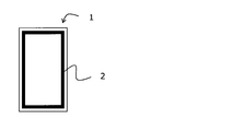
- the filter medium for an immersion type filtration cartridge of the present invention can be made into an immersion type filtration cartridge by adhering it to a resin plate by heat or ultrasonic waves. At that time, it is preferable that the resin plate is sandwiched between the two filter media, and the filter layer, the base material, the resin plate, the base material, and the filter layer are arranged in this order. Further, as the resin plate, PP (polypropylene) resin, ABS resin and the like are preferably exemplified. In such a resin plate, a groove may be formed on the surface of the resin plate to serve as a flow path for filtered water. Further, when the filter medium is adhered to the resin plate, it is preferable to adhere the peripheral portion of the filter medium to the resin plate as shown in FIG. 1 instead of the entire surface of the filter medium. Further, a spacer made of a spunbonded non-woven fabric or the like may be partially interposed between the resin plate and the filter medium (base material).
- the suction filtration operation and the intermittent filtration operation in which the suction filtration is stopped and the aeration only operation is repeated alternately are performed.
- the filter medium While suction filtration is being performed, the filter medium is in a state of sticking to the resin plate due to suction pressure, and while suction filtration is stopped, conversely, the filter medium is in a state of swelling away from the resin plate. Therefore, when the filter medium repeatedly swells and adheres to the resin plate, the load tends to concentrate on the adhesive portion between the filter medium and the resin plate, and the filter medium may break or the filter medium may peel off from the resin plate. ..
- the immersion type filtration cartridge of the present invention uses the above-mentioned filter medium for the immersion type filtration cartridge, it not only has excellent collection performance, but also has a low pressure loss, a large processing amount, and excellent fatigue resistance.
- each measurement item in an Example was measured by the following method.
- the fiber length L was measured by utilizing the length measuring function of the SEM.
- Metsuke The basis weight was measured based on JIS P8124 (method for measuring metric basis weight of paper).
- Thickness The thickness of the filter layer and the base material before bonding was measured based on JIS P8118 (method for measuring the thickness and density of paper and paperboard). The measured load was 75 g / cm 2 and the number of samples was 5, and the average value was calculated.
- a cross section of the filter medium was photographed at a magnification of 350 with a scanning electron microscope (SEM), and the thicknesses of the filtered layer and the substrate after bonding were measured. The number of samples was 6, and the average value was calculated.
- Average pore diameter The average pore diameter ( ⁇ m) was measured with a palm polo meter manufactured by PMI. The number of samples was 6, and the average value was calculated.
- Collection performance When the filter medium was cut to a size of 47 mm ⁇ , 50 ppm of humic acid was dispersed in water, and 250 ml was filtered under a reduced pressure of 0.036 MPa, 1 ⁇ m particles were collected due to the difference in the number of 1 ⁇ m particles before and after filtration.
- a resin plate is fixed to one of the grips of the constant-speed extension type tensile tester, and a filter medium is fixed to the other, and the tension is pulled under the condition of a tensile speed of 50 mm / min to obtain the maximum strength. Read and set as peel strength. It was measured with 3 samples and the average value was calculated.
- Example 1 Polypropylene was used as the island component, and modified polyethylene terephthalate obtained by copolymerizing 4% by weight of polyethylene glycol having an average molecular weight of 4000 as the sea component and 9 mol% of 5-sodium sulfoisophthalic acid was used.
- PP polypropylene
- a core-sheath composite fiber having a polypropylene core and a polyethylene sheath was spun by a conventional method to obtain a binder fiber having a single fiber fineness of 0.3 dtex.
- nanofibers 80% by weight
- binder fibers 20% by weight
- wet papermaking was performed with an inclined short net paper machine and dried at 130 ° C. of a Yankee dryer to obtain a wet nonwoven fabric to be a filtration layer. rice field.
- a core-sheath type composite fiber having a polypropylene core and a polyethylene sheath (40% by weight for a single fiber fineness of 3.3 dtex and 60% by weight for a single fiber fineness of 1.7 dtex), and has a thickness of 0.
- a substrate made of a 208 mm wet non-woven fabric was obtained.
- the filter medium was obtained by adhering the filter layer and the base material by heat adhesion.
- the evaluation results are shown in Table 1.
- Table 2 shows the thickness of the filter medium.
- a polypropylene resin plate was prepared, and a groove was formed on the surface of the polypropylene resin plate to serve as a flow path for filtered water.
- the polypropylene resin plate was sandwiched between the two filter media, and the peripheral portion of the filter media was heat-bonded to obtain an immersion type filtration cartridge.
- the filter layer, the base material, the polypropylene resin plate, the base material, and the filter layer were arranged in this order. Further, a spacer (spunbonded non-woven fabric) was partially interposed between the polypropylene resin plate and the base material (filter medium).
- Example 2 In Example 1, the island component of the nanofibers constituting the filtration layer was changed to polyester (polyethylene terephthalate, PET), and unstretched polyester fibers having a fiber diameter of 1.2 ⁇ m and polyester having a single fiber fineness of 0.2 dtex were used as binder fibers.
- polyester polyethylene terephthalate, PET
- unstretched polyester fibers having a fiber diameter of 1.2 ⁇ m and polyester having a single fiber fineness of 0.2 dtex were used as binder fibers.
- PET polyethylene terephthalate, PET
- unstretched polyester fibers Using unstretched fibers, the ratio of nanofibers, unstretched polyester fibers with a fiber diameter of 1.2 ⁇ m and unstretched polyester fibers with a single fiber fineness of 0.2 dtex was 6: 2: 2 in this order. And said.
- a stretched polyester fiber (60% by weight) having a single fiber fineness of 1.7 dtex and a fiber length of 5 mm and an unstretched polyester fiber (40% by weight) having a single fiber fineness of 1.2 dtex and a fiber length of 5 mm, and has a thickness of 0.
- a substrate made of a wet non-woven fabric of .346 mm was obtained.
- the filter medium was obtained by adhering the filter layer and the base material by heat adhesion.
- the evaluation results are shown in Table 1.
- Table 2 shows the thickness of the filter medium.
- an ABS resin plate was prepared, and a groove was formed on the surface of the ABS resin plate to serve as a flow path for filtered water.
- the ABS resin plate was sandwiched between the two filter media, and the peripheral portion of the filter media was heat-bonded to obtain an immersion type filtration cartridge.
- the filter layer, the base material, the ABS resin plate, the base material, and the filter layer were arranged in this order. Further, a spacer (spunbonded non-woven fabric) was partially interposed between the ABS resin plate and the base material (filter medium).
- Example 3 the fiber diameter of the nanofibers constituting the filtration layer is 200 nm, polyester (polyethylene terephthalate, PET) unstretched fiber having a single fiber fineness of 0.2 dtex is used, and the ratio of the nanofiber to the polyester unstretched fiber is 6. : The same as in Example 2 except that it was set to 4. The evaluation results are shown in Table 1. Table 2 shows the thickness of the filter medium.
- an ABS resin plate was prepared, and a groove was formed on the surface of the ABS resin plate to serve as a flow path for filtered water.
- the ABS resin plate was sandwiched between the two filter media, and the peripheral portion of the filter media was heat-bonded to obtain an immersion type filtration cartridge.
- the filter layer, the base material, the ABS resin plate, the base material, and the filter layer were arranged in this order. Further, a spacer (spunbonded non-woven fabric) was partially interposed between the ABS resin plate and the base material (filter medium).
- Example 4 It was the same as in Example 2 except that the thickness of the base material was 0.127 mm in Example 2. The evaluation results are shown in Table 1. Table 2 shows the thickness of the filter medium.
- Example 5 In Example 3, it was the same as in Example 3 except that the fiber diameter of the nanofibers constituting the filtration layer was 700 nm. The evaluation results are shown in Table 1. Table 2 shows the thickness of the filter medium.
- Example 6 In Example 1, it was the same as in Example 1 except that the fiber diameter of the nanofibers constituting the filtration layer was 700 nm. The evaluation results are shown in Table 1. Table 2 shows the thickness of the filter medium.
- a filter medium for an immersion type filtration cartridge and an immersion type filtration cartridge having excellent collection performance, low pressure loss, large processing amount, and excellent fatigue resistance are provided, and their industrial value is high. It is extremely large.
Abstract
課題は、捕集性能に優れるだけでなく低圧力損失で処理量が大きく、耐疲労性にも優れた浸漬型濾過カートリッジ用濾材および浸漬型濾過カートリッジを提供することであり、解決手段は、濾過層と基材を含む浸漬型濾過カートリッジ用濾材であって、前記濾過層に繊維径1000nm以下のナノファイバーを含ませることである。
Description
本発明は、浸漬型濾過カートリッジ用濾材であって、捕集性能に優れるだけでなく低圧力損失で処理量が大きく、耐疲労性に優れた浸漬型濾過カートリッジ用濾材および浸漬型濾過カートリッジに関する。
膜分離活性汚泥法(MBR)は、下水や工業排水などの有機排水を生物処理槽において活性汚泥処理し、生物処理槽内に浸漬した浸漬型膜分離装置で活性汚泥混合液を固液分離する方法のことである。この方法は、従来の沈殿法と比べて、処理フローが簡単で省スペースであり、濾材により確実に汚泥除去が可能であり、広く普及しつつある(例えば、特許文献1、2、3)。
従来、このような膜分離活性汚泥法に用いられる濾材として、有機繊維からなる多孔質膜が多く用いられてきた。
しかしながら、従来の濾材では、孔径が小さいために圧力損失が大きく、処理量が小さいという問題があった。また、圧力損失が小さく、処理量が大きい膜としては、スパンボンド不織布やメルトブロー不織布などを用いた膜があるが、繊維径が不均一であり、大きな孔が存在することにより、捕集効率が低いという問題があった。これを解決するために、カレンダー加工などにより孔径を小さくすることもあるが、平均孔径が小さくなっても、孔径の均一化にはつながらないだけでなく、密度の上昇により、圧力損失が増大するという問題があった。
一方、濾材は樹脂板の表面に貼り付けた状態(カートリッジ)で使用され、濾過運転が行われる。MBRの運転方法は、一般的に、吸引濾過運転と、吸引濾過を停止して曝気のみの運転を交互に繰り返す、間欠濾過運転が行われる。吸引濾過が行われている間は、吸引圧によって濾材が樹脂板に張り付いた状態になり、一方、吸引濾過を停止している間は、逆に濾材が樹脂板から離れて膨らんだ状態になる。濾材が樹脂板からの膨出と密着を繰り返すことにより、濾材と樹脂板との接着部に負荷が集中しやすく、濾材が破断したり、樹脂板から濾材が剥離するという問題があった。
本発明は上記の背景に鑑みなされたものであり、その目的は、浸漬型濾過カートリッジ用濾材であって、捕集性能に優れるだけでなく低圧力損失で処理量が大きく、耐疲労性にも優れた浸漬型濾過カートリッジ用濾材および浸漬型濾過カートリッジを提供することにある。
本発明者らは上記の課題を達成するため鋭意検討した結果、濾過層と基材を含む浸漬型濾過カートリッジ用濾材において、ナノファイバーを含む薄くて緻密な濾過層と、特定の基材を組み合わせることにより、所望の浸漬型濾過カートリッジ用濾材が得られることを見出し、さらに鋭意検討を重ねることにより本発明を完成するに至った。
さらに詳しく説明すると、繊維径の均一なナノファイバーを用いた濾過層は、孔径の均一な構造を形成することが可能なため、目付けや厚みが小さいにもかかわらず、微小な孔径を持ち、高い濾過効率を有する。したがって、浸漬型濾過カートリッジとして濾材表面のケーキ層形成性に優れ、濾材自身への粒子侵入が極めて少ない。また、このような濾過層に特定の厚みを有する基材を組み合わせることにより、基材が濾過層を補強する役割を果たし、カートリッジとしたときに樹脂板との接着強度を強固にすることができるため、負荷がかかっても、濾材が破断したり、樹脂から剥がれたりすることがなく、耐疲労性に優れる。
かくして、本発明によれば「濾過層と基材を含む浸漬型濾過カートリッジ用濾材であって、前記濾過層が繊維径1000nm以下のナノファイバーを含むことを特徴とする浸漬型濾過カートリッジ用濾材。」が提供される。
その際、前記濾過層がさらにバインダー繊維を含むことが好ましい。また、前記濾過層が湿式不織布からなることが好ましい。また、前記濾過層の平均孔径が0.5μm以下であることが好ましい。また、前記基材が、ポリエステル繊維、ポリフェニレンサルファイド繊維、ポリオレフィン繊維、および脂肪族ポリアミド繊維からなる群より選択されるいずれかを含むことが好ましい。また、前記基材が不織布からなることが好ましい。また、前記基材の厚みが0.1mm以上であることが好ましい。
また、本発明によれば、前記の浸漬型濾過カートリッジ用濾材を用いてなる浸漬型濾過カートリッジが提供される。その際、浸漬型濾過カートリッジがさらに樹脂板を含み、該樹脂板が2枚の前記濾材ではさまれ、前記濾過層、前記基材、前記樹脂板、前記基材、および前記濾過層がこの順に配されていることが好ましい。また、2枚の前記濾材が前記樹脂板に接着していることが好ましい。
本発明によれば、浸漬型濾過カートリッジ用濾材であって、捕集性能に優れるだけでなく低圧力損失で処理量が大きく、耐疲労性にも優れた浸漬型濾過カートリッジ用濾材および浸漬型濾過カートリッジが得られる。
以下、本発明の実施の形態について詳細に説明する。まず、本発明の浸漬型濾過カートリッジ用濾材は、濾過層と基材を含み、かつ前記濾過層に、繊維径が1000nm以下(好ましくは10~900nm、より好ましくは100~650nm、さらに好ましくは100~450nm)のナノファイバーを含む。特に、繊維径が450nm以下(より好ましくは100~400nm)のナノファイバーが、前記濾過層に濾過層重量対比50重量%以上(より好ましくは50~90重量%)含まれることが好ましい。
ここでいうナノファイバーとは、繊維径が1000nm以下であるものを指す。該繊維径はナノファイバーの単繊維径である。繊維径が1000nmよりも大きいと濾過効率が低下するおそれがある。逆に、該繊維径が100nmよりも小さいとナノファイバーの分散性が低下し濾過効率が低下するおそれがある。
前記の繊維径は、透過型電子顕微鏡TEMで、倍率30000倍で単繊維断面写真を撮影し測定することができる。その際、測長機能を有するTEMでは、測長機能を活用して測定することができる。また、測長機能の無いTEMでは、撮った写真を拡大コピーして、縮尺を考慮した上で定規にて測定すればよい。
その際、単繊維の横断面形状が丸断面以外の異型断面である場合には、繊維径は、単繊維の横断面の外接円の直径を用いるものとする。
前記ナノファイバーにおいて繊維長が0.4~1.5mmであることが好ましい。該繊維長が0.4mmよりも小さいと工程性が低下するおそれがある。逆に該繊維長が1.5mmよりも大きいと分散性不良により凝集繊維塊となり濾過効率や強度が低下するおそれがある。また、繊維径Dに対する繊維長Lの比L/Dとしては200~4000(より好ましくは800~2500)の範囲内であることが好ましい。
前記ナノファイバーの繊維種類としては特に限定されないが、ポリエステル繊維、ポリフェニレンサルファイド繊維、ポリオレフィン繊維(ポリプロピレン繊維、ポリエチレン繊維)、脂肪族ポリアミド繊維などが例示される。
前記ナノファイバーの製造方法は特に限定されないが、国際公開第2005/095686号パンフレットや国際公開第2008/130019号パンフレットに開示された方法が好ましい。すなわち、繊維形成性熱可塑性ポリマーからなる島成分と、前記の繊維形成性熱可塑性ポリマーよりもアルカリ水溶液に対して溶解し易いポリマー(以下、「易溶解性ポリマー」ということもある。)からなる海成分とを有する複合繊維にアルカリ減量加工を施し、前記海成分を溶解除去したものであることが好ましい。
ここで、海成分を形成するアルカリ水溶液易溶解性ポリマーの、島成分を形成する繊維形成性熱可塑性ポリマーに対する溶解速度比が200以上(好ましくは300~3000)であると、島分離性が良好となり好ましい。
海成分を形成する易溶解性ポリマーとしては、特に繊維形成性の良いポリエステル類、脂肪族ポリアミド類、ポリエチレンやポリスチレン等のポリオレフィン類を好ましい例としてあげることができる。さらに具体例をあげれば、ポリ乳酸、超高分子量ポリアルキレンオキサイド縮合系ポリマー、ポリアルキレングリコール系化合物と5-ナトリウムスルホイソフタル酸の共重合ポリエステルが、アルカリ水溶液に対して溶解しやすく好ましい。ここでアルカリ水溶液とは、水酸化カリウム、水酸化ナトリウム水溶液などをいう。これ以外にも、海成分と、該海成分を溶解する溶液の組合せとしては、ナイロン6やナイロン66等の脂肪族ポリアミドに対するギ酸、ポリスチレンに対するトリクロロエチレン等やポリエチレン(特に高圧法低密度ポリエチレンや直鎖状低密度ポリエチレン)に対する熱トルエンやキシレン等の炭化水素系溶媒、ポリビニルアルコールやエチレン変性ビニルアルコール系ポリマーに対する熱水を例としてあげることができる。
ポリエステル系ポリマーの中でも、5-ナトリウムスルホイソフタル酸6~12モル%と分子量4000~12000のポリエチレングリコールを3~10重量%共重合させた固有粘度が0.4~0.6のポリエチレンテレフタレート系共重合ポリエステルが好ましい。ここで、5-ナトリウムスルホイソフタル酸は親水性と溶融粘度向上に寄与し、ポリエチレングリコール(PEG)は親水性を向上させる。また、PEGは分子量が大きいほど、その高次構造に起因すると考えられる親水性増加作用があるが、反応性が悪くなってブレンド系になるため、耐熱性や紡糸安定性の面で問題が生じるおそれがある。また、共重合量が10重量%以上になると、溶融粘度が低下するおそれがある。
一方、島成分を形成する難溶解性ポリマーとしては、最終的にナノファイバーを形成するポリマーであり、ポリアミド類、ポリエステル類、ポリオレフィン類、ポリフェニレンサルファイド(PPS)などが好適な例としてあげられる。具体的には、ポリエステル類では、ポリエチレンテレフタレート(以下「PET」と称することもある。)、ポリトリメチレンテレフタレート、ポリブチレンテレフタレート、ポリエチレンナフタレート、これらを主たる繰返し単位とする、イソフタル酸や5-スルホイソフタル酸金属塩等の芳香族ジカルボン酸やアジピン酸、セバシン酸等の脂肪族ジカルボン酸やε-カプロラクトン等のヒドロキシカルボン酸縮合物、ジエチレングリコールやトリメチレングリコール、テトラメチレングリコール、ヘキサメチレングリコール等のグリコール成分等との共重合体が好ましい。また、ポリアミド類では、ナイロン6、ナイロン66等の脂肪族ポリアミド類が好ましい。一方、ポリオレフィン類は、酸やアルカリ等に侵され難いことや、比較的低い融点のためにバインダー成分として使える等の特徴があり、高密度ポリエチレン、中密度ポリエチレン、高圧法低密度ポリエチレン、直鎖状低密度ポリエチレン、アイソタクティックポリプロピレン、エチレンプロピレン共重合体、無水マレイン酸などのビニルモノマーのエチレン共重合体等を好ましい例としてあげることができる。なお、島成分は丸断面に限らず、三角断面や扁平断面などの異型断面であってもよい。
前記の海成分を形成するポリマーおよび島成分を形成するポリマーにおいて、製糸性および抽出後のナノファイバーの物性に影響を及ぼさない範囲で、必要に応じて、有機充填剤、酸化防止剤、熱安定剤、光安定剤、難燃剤、滑剤、帯電防止剤、防錆剤、架橋剤、発泡剤、蛍光剤、表面平滑剤、表面光沢改良剤、フッ素樹脂等の離型改良剤、等の各種添加剤を含んでいてもさしつかえない。
前記の海島型複合繊維において、溶融紡糸時における海成分の溶融粘度が島成分ポリマーの溶融粘度よりも大きいことが好ましい。かかる関係にある場合には、海成分の複合重量比率が40%未満と少なくなっても、島同士の接合を防止しやすい。
好ましい溶融粘度比(海/島)は、1.1~2.0、特に1.3~1.5の範囲である。この比が1.1倍未満の場合には溶融紡糸時に島成分が接合しやすくなり、一方、2.0倍を越える場合には、粘度差が大きすぎるために紡糸調子が低下しやすくなるおそれがある。
次に島数は、100以上(より好ましくは500~2000)であることが好ましい。また、その海島複合重量比率(海:島)は、20:80~80:20の範囲が好ましい。かかる範囲であれば、島間の海成分の厚みを薄くすることができ、海成分の溶解除去が容易となり、島成分のナノファイバーへの転換が容易になるので好ましい。ここで海成分の割合が80%を越える場合には海成分の厚みが厚くなりすぎ、一方20%未満の場合には海成分の量が少なくなりすぎて、島間に接合が発生しやすくなるおそれがある。
溶融紡糸に用いられる口金としては、島成分を形成するための中空ピン群や微細孔群(ピンレス)を有するものなど任意のものを用いることができる。例えば、中空ピンや微細孔より押し出された島成分とその間を埋める形で流路を設計されている海成分流とを合流し、これを圧縮することにより海島断面が形成されるといった紡糸口金でもよい。吐出された海島型複合繊維は冷却風により固化され、所定の引き取り速度に設定した回転ローラーあるいはエジェクターにより引き取られ未延伸糸(複屈折率Δnが0.05以下であることが好ましい。)を得る。この引き取り速度は特に限定されないが、200~5000m/分であることが好ましい。200m/分未満では生産性が低下するおそれがある。また、5000m/分超では紡糸安定性が低下するおそれがある。
得られた未延伸糸は、必要に応じてそのままカット工程あるいはその後の抽出工程(アルカリ減量加工)に供してもよいし、延伸工程や熱処理工程を経由して延伸糸とした後、カット工程あるいはその後の抽出工程(アルカリ減量加工)に供してもよい。その際、延伸工程は紡糸と延伸を別ステップで行う別延方式でもよいし、一工程内で紡糸後直ちに延伸を行う直延方式を用いてもよい。カット工程と抽出工程の順番は逆にしてもよい。
かかるカットは、未延伸糸または延伸糸をそのまま、または数十本~数百万本単位に束ねたトウにしてギロチンカッターやロータリーカッターなどでカットすることが好ましい。
前記の海島型複合繊維にアルカリ減量加工を施してナノファイバーとする際、繊維のアルカリ液に対する比率(浴比)は0.1~5%であることが好ましく、さらには0.4~3%であることが好ましい。0.1%未満では繊維とアルカリ液の接触は多いものの、排水等の工程性が困難となるおそれがある。一方、5%を越えると繊維量が多過ぎるため、アルカリ減量加工時に繊維同士の絡み合いが発生するおそれがある。なお、浴比は下記式にて定義する。
浴比(%)=(繊維重量(gr)/アルカリ水溶液重量(gr))×100
また、アルカリ減量加工の処理時間は5~60分であることが好ましく、さらには10~30分であることが好ましい。5分未満ではアルカリ減量が不十分となるおそれがある。一方、60分を越えると島成分までも減量されるおそれがある。
浴比(%)=(繊維重量(gr)/アルカリ水溶液重量(gr))×100
また、アルカリ減量加工の処理時間は5~60分であることが好ましく、さらには10~30分であることが好ましい。5分未満ではアルカリ減量が不十分となるおそれがある。一方、60分を越えると島成分までも減量されるおそれがある。
また、アルカリ減量加工において、アルカリ濃度は2~10重量%であることが好ましい。2重量%未満では、アルカリ不足となり、減量速度が極めて遅くなるおそれがある。一方、10重量%を越えるとアルカリ減量が進みすぎ、島部分まで減量されるおそれがある。
アルカリ減量の方法としては、海島型複合繊維をアルカリ液に投入し、所定の条件、時間でアルカリ減量処理した後に一度、脱水工程を経てから、再度、水中に投入し、酢酸、シュウ酸などの有機酸を使用して中和、希釈を進め最終的に脱水する方法や、または、所定の時間アルカリ減量処理した後に、先に中和処理を施し、さらに水を注入し希釈を進めその後脱水をする方法等があげられる。前者では、バッチ式に処理する為、少量での製造(加工)を行えることができるものの、中和処理に時間を要するため少し生産性が悪い。後者は半連続生産が可能であるが、中和処理時に多くの酸系水溶液及び希釈のために多くの水を必要とするという問題点がある。処理設備は何ら制限されるものではないが、脱水時に繊維脱落を防止する観点から、特許第3678511号公報に開示されているような開口率(単位面積当たりの開口部分の面積比率)が10~50%であるメッシュ状物(例えば非アルカリ加水分解性袋など)を使用することが好ましい。該開口率が10%未満では水分の抜けが極めて悪く、50%を超えると、繊維の脱落が発生するおそれがある。
さらには、アルカリ減量加工の後、繊維の分散性を高めるために分散剤(例えば、高松油脂(株)製の型式YM-81)を繊維表面に、繊維重量に対して0.1~5.0重量%付着させることが好ましい。
本発明の浸漬型濾過カートリッジ用濾材において、濾過層は湿式不織布からなることが好ましい。湿式不織布は、スパンボンド法やメルトブロー法、エレクトロスピニング法等により作製された不織布と比較して、目付け、繊維径、通気度などのフィルター性能に関わる性質のばらつきが小さく、濾過効率に優れることから好ましい。
前記濾過層を構成する繊維の種類は1種類でもよいが、2種類以上(好ましくは2~4種類)であることが好ましい。その際、前記ナノファイバーがバインダー効果を有する繊維であってもよいし、バインダー効果を有さない繊維(非バインダー繊維)であってもよい。
前記ナノファイバーが非バインダー繊維である場合、濾過層がさらにバインダー繊維を含むことが好ましい。その際、バインダー繊維の重量比率が濾過層重量に対して10重量%以上(好ましくは10~50重量%)の範囲内であることが好ましい。また、バインダー繊維としては、単繊維繊度が1.0dtex以下(より好ましくは0.0001~0.3dtex)の繊維が好ましい。バインダー繊維の繊維長は、3~10mmであることが好ましい。
バインダー繊維は熱接着性繊維である。濾過層にバインダー繊維が含まれることにより、不織布の強度やネットワーク構造および収縮による嵩向上などの効果が得られる。
前記バインダー繊維の繊維種類としては特に限定されず、未延伸糸や複合繊維であってもよい。例えば、ポリエステル未延伸繊維やポリオレフィン繊維などが例示される。
バインダー繊維のうち、未延伸繊維としては、紡糸速度が600~1500m/分で紡糸された未延伸ポリエステル繊維が好ましい。ポリエステルとは、ポリエチレンテレフタレート、ポリトリメチレンテレタレート、ポリブチレンテレフタレートが挙げられ、好ましくは生産性、水への分散性などの理由から、ポリエチレンテレフタレートやそれを主成分とする共重合ポリエステルが好ましい。
また、バインダー繊維のうち、複合繊維としては、抄紙時のドライヤー温度により融着接着効果を発現するポリマー成分、たとえば非結晶性共重合ポリエステルやポリオレフィンが鞘部に配置され、これらのポリマーより融点が20℃以上高い他のポリマーが芯部に配置された芯鞘型複合繊維が好ましい。また、偏心芯鞘型複合繊維、サイドバイサイド型複合繊維などの形態も使用できる。
さらに、ナノファイバーの分散を助けるとともに、空隙率の向上にも寄与する非バインダー繊維でありナノファイバーよりも太繊度の繊維が前記濾過層に含まれていてもよい。ナノファイバーよりも太繊度の繊維としては、繊維径が均一で分散性のよい前記のようなポリエステル繊維が好ましい。また、目的に応じて、種々の紙用繊維素材が使用可能である。例えば、木材パルプ、天然パルプ、アラミドやポリエチレンを主成分とする合成パルプ、ナイロン、アクリル、ビニロン、レーヨン等の成分を含む合成繊維または半合成繊維を混合、添加してもよい。
前記の湿式不織布は、例えば、前記ナノファイバーと必要に応じてバインダー繊維などを用いて通常の長網抄紙機、短網抄紙機、丸網抄紙機などを用いて抄紙した後、前記ナノファイバーやバインダー繊維を熱接着することにより得られる。
ここで、濾過層の平均孔径が0.5μm以下(より好ましくは0.01~0.45μm)であることが好ましい。かかる平均孔径が0.5μmより大きいと捕集性能や耐ファウリング性が低下するおそれがある。なお、平均孔径は、PMI社製パームポロメーターによりサンプル数6で測定し、平均値を求めるものとする。
本発明の浸漬型濾過カートリッジ用濾材は、前記濾過層に加えて基材(支持層)をも含む。濾材を補強する役目を果たす前記基材の厚みは、0.1mm以上であることが好ましい。厚みが0.1mmより小さいと、濾過層と貼り合わせて濾材とした場合に、濾材の強度が小さく、濾材を樹脂板に接着させて膜カートリッジとした場合に、曝気などに対する物理的耐久性が得られないだけでなく、樹脂板との接着部において、濾材が破れたり孔があいたりするおそれがある。また、厚みが大きすぎても高い水処理量が得られなくなるおそれがあるため、0.1~2.0mmが好ましく例示される。
前記基材は不織布であることが好ましい。密度として低密度が好ましく、0.1~0.7g/cm3の範囲内であることが好ましい。該密度が0.1g/cm3より小さいと、取扱い性が悪くなるおそれがある。逆に、該密度が0.7g/cm3より大きいと、高い水処理量が得られなくなるおそれがある。
基材は湿式不織布に限らず、スパンボンド法やメルトブロー法、エレクトロスピニング法等により作製された不織布であってもよい。
また、基材を構成する繊維としては、前記のようなポリエステル繊維や、ポリフェニレンサルファイド繊維、ポリオレフィン繊維(ポリプロピレン繊維、ポリエチレン繊維)、脂肪族ポリアミド繊維などが例示される。なお、かかる繊維は未延伸繊維や、芯鞘型複合繊維やサイドバイサイド型複合繊維であってもよい。その際、かかる繊維の単繊維繊度は1.0dtex以上(より好ましくは1.0~3.0dtex)であることが好ましい。前記単繊維繊度が1.0dtex以上の場合、基材の密度を0.1~0.7g/cm3の範囲内に保ちながら、基材としての十分な強度が得られ好ましい。
本発明の浸漬型濾過カートリッジ用濾材は前記の構成を有するので、捕集性能に優れるだけでなく低圧力損失で処理量が大きく、また耐疲労性に優れる。
かかる濾材の厚みとしては、0.1~2.0mmが好ましく例示される。また、かかる濾材において、濾材と樹脂板との剥離強度が40N/50mm以上(より好ましくは40~300N/50mm)であることが好ましい。剥離強度が40N/50mmより小さいと、樹脂板との接着が弱いために、濾材が樹脂板から剥がれてしまうおそれがある。ただし、かかる剥離強度は以下の方法で測定するものとする。すなわち、まず、樹脂板に濾材を、基材が樹脂板側に位置するよう配し、超音波接着により接着させ、巾50mmとなるようにサンプルを切り出し、試験片とする。次いで、図2に示すように、定速伸長型引張試験機のつかみ部の一方に樹脂板を、もう一方に濾材を固定し、引張速度が50mm/分の条件で引張り、強力の最大値を読み取り、剥離強度とする。サンプル数3で測定し、平均値を求める。
本発明の浸漬型濾過カートリッジ用濾材は、熱または超音波により樹脂板に接着させることにより、浸漬型濾過カートリッジとすることができる。その際、樹脂板が2枚の前記濾材ではさまれ、前記濾過層、前記基材、前記樹脂板、前記基材、および前記濾過層がこの順に配されていることが好ましい。また、前記樹脂板としては、PP(ポリプロピレン)樹脂やABS樹脂などが好適に例示される。かかる樹脂板には、樹脂版の表面に溝を形成して濾過された水の流路としてもよい。また、濾材を樹脂板に接着させる際、濾材全面ではなく図1に示すように濾材の周辺部を樹脂板に接着させることが好ましい。さらには、スパンボンド不織布などからなるスペーサを樹脂板と濾材(基材)との間に部分的に介在させてもよい。
濾過運転の際は、一般的に、吸引濾過運転と、吸引濾過を停止して曝気のみの運転を交互に繰り返す、間欠濾過運転が行われる。吸引濾過が行われている間は、吸引圧によって濾材が樹脂板に張り付いた状態になり、吸引濾過を停止している間は、逆に濾材が樹脂板から離れて膨らんだ状態になる。したがって、濾材が樹脂板からの膨出と密着を繰り返すことにより、濾材と樹脂板との接着部に負荷が集中しやすく、濾材が破断したり、樹脂板から濾材が剥離したりするおそれがある。
本発明の浸漬型濾過カートリッジは、前記の浸漬型濾過カートリッジ用濾材を用いているので、捕集性能に優れるだけでなく低圧力損失で処理量が大きく、また耐疲労性に優れる。
次に本発明の実施例および比較例を詳述するが、本発明はこれらによって限定されるものではない。なお、実施例中の各測定項目は下記の方法で測定した。
(1)繊維径
透過型電子顕微鏡TEM(測長機能付)を使用し、倍率30000倍で繊維断面写真を撮影し測定した。ただし、繊維径は、単繊維横断面におけるその外接円の直径を用いた(n数5の平均値)。
(2)繊維長
走査型電子顕微鏡(SEM)により、海成分溶解除去前の極細短繊維(短繊維A)を基盤上に寝かせた状態とし、20~500倍で繊維長Lを測定した(サンプル数5の平均値)。その際、SEMの測長機能を活用して繊維長Lを測定した。
(3)目付け
JIS P8124(紙のメートル坪量測定方法)に基づいて目付けを測定した。
(4)厚み
濾過層と基材について、JIS P8118(紙及び板紙の厚さと密度の測定方法)に基づいて貼り合わせ前の厚さを測定した。測定荷重は75g/cm2にて、サンプル数5で測定し、平均値を求めた。
また、走査型電子顕微鏡(SEM)により、濾材の断面を350倍で撮影し、貼り合わせ後の濾過層と基材それぞれの厚みを測定した。サンプル数6で測定し、平均値を求めた。
(5)平均孔径
PMI社製パームポロメーターにより平均孔径(μm)を測定した。サンプル数6で測定し、平均値を求めた。
(6)捕集性能
濾材を47mmφのサイズにカットし、フミン酸50ppmを水に分散させ、0.036MPa減圧下で250ml濾過させた際、濾過前後の1μm粒子個数の差から、1μm粒子の捕集率(%)を求め、99%以上であった場合「〇」(良好)、95~99%であった場合「△」(普通)、95%以下であった場合を「×(不良)」とした。
(7)剥離強度
樹脂板に濾材を、基材が樹脂板側に位置するよう配し、超音波接着により接着させ、巾50mmとなるようにサンプルを切り出し、試験片とした。次いで、図2に示すように、定速伸長型引張試験機のつかみ部の一方に樹脂板を、もう一方に濾材を固定し、引張速度が50mm/分の条件で引張り、強力の最大値を読み取り、剥離強度とした。サンプル数3で測定し、平均値を求めた。
[実施例1]
島成分としてポリプロピレン、海成分として平均分子量4000のポリエチレングリコールを4重量%、5-ナトリウムスルホイソフタル酸を9mol%共重合した改質ポリエチレンテレフタレートを使用し、海:島=50:50、島数=836の海島型複合未延伸糸を、紡糸温度210℃、紡糸速度1500m/分で溶融紡糸して一旦巻き取った。海成分と島成分とのアルカリ減量速度比は1000倍であった。これを3倍に延伸し、ギロチンカッターで0.4mmにカットし、海島型複合繊維を得た。これを4%NaOH水溶液で50℃にて50%減量し、繊維径400nm、カット長0.4mmのポリプロピレン(PP)繊維からなるナノファイバーを得て主体繊維とした。
島成分としてポリプロピレン、海成分として平均分子量4000のポリエチレングリコールを4重量%、5-ナトリウムスルホイソフタル酸を9mol%共重合した改質ポリエチレンテレフタレートを使用し、海:島=50:50、島数=836の海島型複合未延伸糸を、紡糸温度210℃、紡糸速度1500m/分で溶融紡糸して一旦巻き取った。海成分と島成分とのアルカリ減量速度比は1000倍であった。これを3倍に延伸し、ギロチンカッターで0.4mmにカットし、海島型複合繊維を得た。これを4%NaOH水溶液で50℃にて50%減量し、繊維径400nm、カット長0.4mmのポリプロピレン(PP)繊維からなるナノファイバーを得て主体繊維とした。
一方、芯がポリプロピレン、鞘がポリエチレンである芯鞘複合繊維を常法により紡糸し、単繊維繊度0.3dtexのバインダー繊維とした。
次いで、前記ナノファイバー(80重量%)と、バインダー繊維(20重量%)を混合撹拌した後、傾斜短網抄紙機で湿式抄紙を行いヤンキードライヤー130℃で乾燥し濾過層となる湿式不織布を得た。
また、芯がポリプロピレン、鞘がポリエチレンの芯鞘型複合繊維(単繊維繊度3.3dtexのものを40重量%、単繊維繊度1.7dtexのものを60重量%)で構成され、厚みが0.208mmの湿式不織布からなる基材を得た。
次いで、前記濾過層と基材とを熱接着により貼り合わせることにより、濾材を得た。評価結果を表1に示す。また、かかる濾材の厚みを表2に示す。
一方、ポリプロピレン樹脂板を用意し、該ポリプロピレン樹脂板の表面に、溝を形成して濾過された水の流路とした。
次いで、該ポリプロピレン樹脂板を2枚の前記濾材ではさみ、濾材の周辺部を熱接着させることにより浸漬型濾過カートリッジを得た。その際、濾過層、基材、ポリプロピレン樹脂板、基材、および濾過層がこの順になるよう配した。また、ポリプロピレン樹脂板と基材(濾材)との間に部分的にスペーサ(スパンボンド不織布)を介在させた。
[実施例2]
実施例1において、濾過層を構成するナノファイバーの島成分をポリエステル(ポリエチレンテレフタレート、PET)に変更し、バインダー繊維として繊維径1.2μmのポリエステル未延伸繊維と単繊維繊度0.2dtexのポリエステル(ポリエチレンテレフタレート、PET)未延伸繊維を用い、ナノファイバーと、繊維径1.2μmのポリエステル未延伸繊維と、単繊維繊度0.2dtexのポリエステル未延伸繊維との比をこの順で6:2:2とした。
実施例1において、濾過層を構成するナノファイバーの島成分をポリエステル(ポリエチレンテレフタレート、PET)に変更し、バインダー繊維として繊維径1.2μmのポリエステル未延伸繊維と単繊維繊度0.2dtexのポリエステル(ポリエチレンテレフタレート、PET)未延伸繊維を用い、ナノファイバーと、繊維径1.2μmのポリエステル未延伸繊維と、単繊維繊度0.2dtexのポリエステル未延伸繊維との比をこの順で6:2:2とした。
また、単繊維繊度1.7dtex、繊維長5mmの延伸ポリエステル繊維(60重量%)と、単繊維繊度1.2dtex、繊維長5mmの未延伸ポリエステル繊維(40重量%)で構成され、厚みが0.346mmの湿式不織布からなる基材を得た。
次いで、前記濾過層と基材とを熱接着により貼り合わせることにより、濾材を得た。評価結果を表1に示す。また、かかる濾材の厚みを表2に示す。
一方、ABS樹脂板を用意し、該ABS樹脂板表面に、溝を形成して濾過された水の流路とした。次いで、該ABS樹脂板を2枚の前記濾材ではさみ、濾材の周辺部を熱接着させることにより浸漬型濾過カートリッジを得た。その際、濾過層、基材、ABS樹脂板、基材、および濾過層がこの順になるよう配した。また、ABS樹脂板と基材(濾材)との間に部分的にスペーサ(スパンボンド不織布)を介在させた。
[実施例3]
実施例2において、濾過層を構成するナノファイバーの繊維径を200nmとし、単繊維繊度0.2dtexのポリエステル(ポリエチレンテレフタレート、PET)未延伸繊維を用い、ナノファイバーとポリエステル未延伸繊維の比を6:4とした以外は、実施例2と同様とした。評価結果を表1に示す。また、かかる濾材の厚みを表2に示す。
実施例2において、濾過層を構成するナノファイバーの繊維径を200nmとし、単繊維繊度0.2dtexのポリエステル(ポリエチレンテレフタレート、PET)未延伸繊維を用い、ナノファイバーとポリエステル未延伸繊維の比を6:4とした以外は、実施例2と同様とした。評価結果を表1に示す。また、かかる濾材の厚みを表2に示す。
一方、ABS樹脂板を用意し、該ABS樹脂板表面に、溝を形成して濾過された水の流路とした。次いで、該ABS樹脂板を2枚の前記濾材ではさみ、濾材の周辺部を熱接着させることにより浸漬型濾過カートリッジを得た。その際、濾過層、基材、ABS樹脂板、基材、および濾過層がこの順になるよう配した。また、ABS樹脂板と基材(濾材)との間に部分的にスペーサ(スパンボンド不織布)を介在させた。
[実施例4]
実施例2において基材の厚みを0.127mmとした以外は、実施例2と同様とした。評価結果を表1に示す。また、かかる濾材の厚みを表2に示す。
実施例2において基材の厚みを0.127mmとした以外は、実施例2と同様とした。評価結果を表1に示す。また、かかる濾材の厚みを表2に示す。
[実施例5]
実施例3において、濾過層を構成するナノファイバーの繊維径を700nmとした以外は、実施例3と同様とした。評価結果を表1に示す。また、かかる濾材の厚みを表2に示す。
実施例3において、濾過層を構成するナノファイバーの繊維径を700nmとした以外は、実施例3と同様とした。評価結果を表1に示す。また、かかる濾材の厚みを表2に示す。
[実施例6]
実施例1において、濾過層を構成するナノファイバーの繊維径を700nmとした以外は、実施例1と同様とした。評価結果を表1に示す。また、かかる濾材の厚みを表2に示す。
実施例1において、濾過層を構成するナノファイバーの繊維径を700nmとした以外は、実施例1と同様とした。評価結果を表1に示す。また、かかる濾材の厚みを表2に示す。
[比較例1]
市販品であるMBR膜カートリッジから、濾材を切り出したところ、塩素化ポリエチレンからなるメンブレンであった。この濾材についても、同様の評価を行った。評価結果を表1に示す。
市販品であるMBR膜カートリッジから、濾材を切り出したところ、塩素化ポリエチレンからなるメンブレンであった。この濾材についても、同様の評価を行った。評価結果を表1に示す。


本発明によれば、捕集性能に優れるだけでなく低圧力損失で処理量が大きく、耐疲労性にも優れた浸漬型濾過カートリッジ用濾材および浸漬型濾過カートリッジが提供され、その工業的価値は極めて大である。
1:濾材
2:接着部
3:樹脂板
4:チャック
2:接着部
3:樹脂板
4:チャック
Claims (10)
- 濾過層と基材を含む浸漬型濾過カートリッジ用濾材であって、前記濾過層が繊維径1000nm以下のナノファイバーを含むことを特徴とする浸漬型濾過カートリッジ用濾材。
- 前記濾過層がさらにバインダー繊維を含む、請求項1に記載の浸漬型濾過カートリッジ用濾材。
- 前記濾過層が湿式不織布からなる、請求項1または請求項2の浸漬型濾過カートリッジ用濾材。
- 前記濾過層の平均孔径が0.5μm以下である、請求項1~3のいずれかに記載の浸漬型濾過カートリッジ用濾材。
- 前記基材が、ポリエステル繊維、ポリフェニレンサルファイド繊維、ポリオレフィン繊維、および脂肪族ポリアミド繊維からなる群より選択されるいずれかを含む、請求項1~4のいずれかに記載の浸漬型濾過カートリッジ用濾材。
- 前記基材が不織布からなる、請求項1~5のいずれかに記載の浸漬型濾過カートリッジ用濾材。
- 前記基材の厚みが0.1mm以上である、請求項1~6のいずれかに記載の浸漬型濾過カートリッジ用濾材。
- 請求項1~7のいずれかに記載の浸漬型濾過カートリッジ用濾材を用いてなる浸漬型濾過カートリッジ。
- 浸漬型濾過カートリッジがさらに樹脂板を含み、該樹脂板が2枚の前記濾材ではさまれ、前記濾過層、前記基材、前記樹脂板、前記基材、および前記濾過層がこの順に配されてなる、請求項8に記載の浸漬型濾過カートリッジ。
- 2枚の前記濾材が前記樹脂板に接着してなる、請求項9に記載の浸漬型濾過カートリッジ。
Priority Applications (1)
| Application Number | Priority Date | Filing Date | Title |
|---|---|---|---|
| JP2022522545A JPWO2021229925A1 (ja) | 2020-05-12 | 2021-03-25 |
Applications Claiming Priority (2)
| Application Number | Priority Date | Filing Date | Title |
|---|---|---|---|
| JP2020083713 | 2020-05-12 | ||
| JP2020-083713 | 2020-05-12 |
Publications (1)
| Publication Number | Publication Date |
|---|---|
| WO2021229925A1 true WO2021229925A1 (ja) | 2021-11-18 |
Family
ID=78525663
Family Applications (1)
| Application Number | Title | Priority Date | Filing Date |
|---|---|---|---|
| PCT/JP2021/012449 WO2021229925A1 (ja) | 2020-05-12 | 2021-03-25 | 浸漬型濾過カートリッジ用濾材および浸漬型濾過カートリッジ |
Country Status (3)
| Country | Link |
|---|---|
| JP (1) | JPWO2021229925A1 (ja) |
| TW (1) | TW202206171A (ja) |
| WO (1) | WO2021229925A1 (ja) |
Citations (6)
| Publication number | Priority date | Publication date | Assignee | Title |
|---|---|---|---|---|
| JP2001129321A (ja) * | 1999-11-01 | 2001-05-15 | Daicel Chem Ind Ltd | 固液分離装置の運転方法 |
| JP2016159197A (ja) * | 2015-02-27 | 2016-09-05 | 三菱製紙株式会社 | 膜分離活性汚泥処理用半透膜用支持体 |
| JP2017121606A (ja) * | 2016-01-07 | 2017-07-13 | 三菱製紙株式会社 | 膜分離活性汚泥処理用半透膜用支持体及び濾過膜 |
| JP2018114430A (ja) * | 2017-01-16 | 2018-07-26 | 帝人フロンティア株式会社 | 浸漬型濾過カートリッジ用濾材およびその製造方法および浸漬型濾過カートリッジ |
| JP2018192420A (ja) * | 2017-05-17 | 2018-12-06 | 帝人フロンティア株式会社 | 浸漬型濾過カートリッジ用濾材および浸漬型濾過カートリッジ |
| JP2019198833A (ja) * | 2018-05-17 | 2019-11-21 | 帝人フロンティア株式会社 | 浸漬型濾過カートリッジ用濾材および浸漬型濾過カートリッジ |
-
2021
- 2021-03-25 WO PCT/JP2021/012449 patent/WO2021229925A1/ja active Application Filing
- 2021-03-25 JP JP2022522545A patent/JPWO2021229925A1/ja active Pending
- 2021-04-15 TW TW110113507A patent/TW202206171A/zh unknown
Patent Citations (6)
| Publication number | Priority date | Publication date | Assignee | Title |
|---|---|---|---|---|
| JP2001129321A (ja) * | 1999-11-01 | 2001-05-15 | Daicel Chem Ind Ltd | 固液分離装置の運転方法 |
| JP2016159197A (ja) * | 2015-02-27 | 2016-09-05 | 三菱製紙株式会社 | 膜分離活性汚泥処理用半透膜用支持体 |
| JP2017121606A (ja) * | 2016-01-07 | 2017-07-13 | 三菱製紙株式会社 | 膜分離活性汚泥処理用半透膜用支持体及び濾過膜 |
| JP2018114430A (ja) * | 2017-01-16 | 2018-07-26 | 帝人フロンティア株式会社 | 浸漬型濾過カートリッジ用濾材およびその製造方法および浸漬型濾過カートリッジ |
| JP2018192420A (ja) * | 2017-05-17 | 2018-12-06 | 帝人フロンティア株式会社 | 浸漬型濾過カートリッジ用濾材および浸漬型濾過カートリッジ |
| JP2019198833A (ja) * | 2018-05-17 | 2019-11-21 | 帝人フロンティア株式会社 | 浸漬型濾過カートリッジ用濾材および浸漬型濾過カートリッジ |
Also Published As
| Publication number | Publication date |
|---|---|
| TW202206171A (zh) | 2022-02-16 |
| JPWO2021229925A1 (ja) | 2021-11-18 |
Similar Documents
| Publication | Publication Date | Title |
|---|---|---|
| EP2138634B1 (en) | Wet-laid non-woven fabric and filter | |
| JP6695420B2 (ja) | 液体フィルター用ろ材および液体フィルター | |
| JP5607748B2 (ja) | フィルター用多層ろ材およびフィルター | |
| JP6397121B2 (ja) | バグフィルター用ろ過布およびその製造方法およびバグフィルター | |
| KR101441723B1 (ko) | 박엽지 | |
| JP4950472B2 (ja) | 短カットナノファイバーの製造方法 | |
| JP2010070870A (ja) | 不織布の製造方法および不織布および不織布構造体および繊維製品 | |
| JP2014074246A (ja) | 液体ろ過フィルター用湿式不織布および液体ろ過フィルター | |
| JP4994313B2 (ja) | 短カットナノファイバーの製造方法および湿式不織布の製造方法 | |
| JP7028621B2 (ja) | 不織布およびバグフィルター用濾材 | |
| JP6884033B2 (ja) | 浸漬型濾過カートリッジ用濾材および浸漬型濾過カートリッジ | |
| JP2019199668A (ja) | マスク用濾材およびマスク | |
| JP2012092461A (ja) | 薄葉紙 | |
| WO2021229925A1 (ja) | 浸漬型濾過カートリッジ用濾材および浸漬型濾過カートリッジ | |
| JP2012237084A (ja) | フィルター用不織布およびエアーフィルター | |
| JP6829083B2 (ja) | 浸漬型濾過カートリッジ用濾材およびその製造方法および浸漬型濾過カートリッジ | |
| JP2019198833A (ja) | 浸漬型濾過カートリッジ用濾材および浸漬型濾過カートリッジ | |
| JP2023128651A (ja) | 浸漬型濾過カートリッジ用濾材および浸漬型濾過カートリッジ | |
| JP7044526B2 (ja) | 液体フィルター用ろ材 | |
| JP2017170352A (ja) | 燃料フィルター用ろ材およびその製造方法およびガソリンフィルター | |
| JP2022142245A (ja) | 浸漬型濾過カートリッジ用濾材 | |
| JP2008136896A (ja) | フィルターおよびフィルターエレメント | |
| JP2014201847A (ja) | エアレイド不織布および繊維製品 | |
| JP2022094613A (ja) | 不織布、短カット熱接着性繊維およびフィルター | |
| JP2023012165A (ja) | マスク用濾材およびマスク |
Legal Events
| Date | Code | Title | Description |
|---|---|---|---|
| 121 | Ep: the epo has been informed by wipo that ep was designated in this application |
Ref document number: 21804533 Country of ref document: EP Kind code of ref document: A1 |
|
| ENP | Entry into the national phase |
Ref document number: 2022522545 Country of ref document: JP Kind code of ref document: A |
|
| NENP | Non-entry into the national phase |
Ref country code: DE |
|
| 122 | Ep: pct application non-entry in european phase |
Ref document number: 21804533 Country of ref document: EP Kind code of ref document: A1 |