WO2021229925A1 - Matériau de filtration pour cartouche de filtration de type à immersion, et cartouche de filtration de type à immersion - Google Patents
Matériau de filtration pour cartouche de filtration de type à immersion, et cartouche de filtration de type à immersion Download PDFInfo
- Publication number
- WO2021229925A1 WO2021229925A1 PCT/JP2021/012449 JP2021012449W WO2021229925A1 WO 2021229925 A1 WO2021229925 A1 WO 2021229925A1 JP 2021012449 W JP2021012449 W JP 2021012449W WO 2021229925 A1 WO2021229925 A1 WO 2021229925A1
- Authority
- WO
- WIPO (PCT)
- Prior art keywords
- filter medium
- fiber
- immersion type
- filtration
- resin plate
- Prior art date
Links
- 238000001914 filtration Methods 0.000 title claims abstract description 97
- 239000000463 material Substances 0.000 title claims abstract description 47
- 239000000835 fiber Substances 0.000 claims abstract description 148
- 239000002121 nanofiber Substances 0.000 claims abstract description 32
- 229920005989 resin Polymers 0.000 claims description 48
- 239000011347 resin Substances 0.000 claims description 48
- 238000007654 immersion Methods 0.000 claims description 42
- 229920000728 polyester Polymers 0.000 claims description 25
- 239000011230 binding agent Substances 0.000 claims description 22
- 239000004745 nonwoven fabric Substances 0.000 claims description 20
- 239000011148 porous material Substances 0.000 claims description 11
- 229920000098 polyolefin Polymers 0.000 claims description 8
- 239000004953 Aliphatic polyamide Substances 0.000 claims description 7
- 229920003231 aliphatic polyamide Polymers 0.000 claims description 7
- 239000000758 substrate Substances 0.000 claims description 7
- 239000004734 Polyphenylene sulfide Substances 0.000 claims description 6
- 229920000069 polyphenylene sulfide Polymers 0.000 claims description 6
- 238000012545 processing Methods 0.000 abstract description 16
- 239000002585 base Substances 0.000 description 35
- -1 polypropylene Polymers 0.000 description 35
- 238000000034 method Methods 0.000 description 24
- 239000002131 composite material Substances 0.000 description 18
- 239000003513 alkali Substances 0.000 description 16
- 229920000642 polymer Polymers 0.000 description 16
- 208000016261 weight loss Diseases 0.000 description 14
- 239000004743 Polypropylene Substances 0.000 description 12
- 229920000139 polyethylene terephthalate Polymers 0.000 description 12
- 239000005020 polyethylene terephthalate Substances 0.000 description 12
- 229920001155 polypropylene Polymers 0.000 description 12
- XLYOFNOQVPJJNP-UHFFFAOYSA-N water Substances O XLYOFNOQVPJJNP-UHFFFAOYSA-N 0.000 description 12
- 229920000122 acrylonitrile butadiene styrene Polymers 0.000 description 11
- 239000012528 membrane Substances 0.000 description 9
- 238000009987 spinning Methods 0.000 description 9
- 239000007864 aqueous solution Substances 0.000 description 8
- 238000011156 evaluation Methods 0.000 description 8
- 239000000123 paper Substances 0.000 description 8
- 238000000967 suction filtration Methods 0.000 description 8
- 230000004580 weight loss Effects 0.000 description 8
- 239000004698 Polyethylene Substances 0.000 description 7
- 229920000573 polyethylene Polymers 0.000 description 7
- HEMHJVSKTPXQMS-UHFFFAOYSA-M Sodium hydroxide Chemical compound [OH-].[Na+] HEMHJVSKTPXQMS-UHFFFAOYSA-M 0.000 description 6
- 239000000853 adhesive Substances 0.000 description 6
- 239000010802 sludge Substances 0.000 description 6
- 239000013585 weight reducing agent Substances 0.000 description 6
- 239000002202 Polyethylene glycol Substances 0.000 description 5
- 230000001070 adhesive effect Effects 0.000 description 5
- 230000002093 peripheral effect Effects 0.000 description 5
- 229920001223 polyethylene glycol Polymers 0.000 description 5
- 238000005520 cutting process Methods 0.000 description 4
- 230000000694 effects Effects 0.000 description 4
- 238000000605 extraction Methods 0.000 description 4
- 229920001684 low density polyethylene Polymers 0.000 description 4
- 239000004702 low-density polyethylene Substances 0.000 description 4
- 239000000155 melt Substances 0.000 description 4
- 125000006850 spacer group Chemical group 0.000 description 4
- QTBSBXVTEAMEQO-UHFFFAOYSA-N Acetic acid Chemical compound CC(O)=O QTBSBXVTEAMEQO-UHFFFAOYSA-N 0.000 description 3
- MUBZPKHOEPUJKR-UHFFFAOYSA-N Oxalic acid Chemical compound OC(=O)C(O)=O MUBZPKHOEPUJKR-UHFFFAOYSA-N 0.000 description 3
- KWYUFKZDYYNOTN-UHFFFAOYSA-M Potassium hydroxide Chemical compound [OH-].[K+] KWYUFKZDYYNOTN-UHFFFAOYSA-M 0.000 description 3
- YXFVVABEGXRONW-UHFFFAOYSA-N Toluene Chemical compound CC1=CC=CC=C1 YXFVVABEGXRONW-UHFFFAOYSA-N 0.000 description 3
- 238000005273 aeration Methods 0.000 description 3
- 239000012670 alkaline solution Substances 0.000 description 3
- 239000003795 chemical substances by application Substances 0.000 description 3
- MTHSVFCYNBDYFN-UHFFFAOYSA-N diethylene glycol Chemical compound OCCOCCO MTHSVFCYNBDYFN-UHFFFAOYSA-N 0.000 description 3
- 238000004090 dissolution Methods 0.000 description 3
- 230000006872 improvement Effects 0.000 description 3
- 238000005259 measurement Methods 0.000 description 3
- 238000002074 melt spinning Methods 0.000 description 3
- 238000006386 neutralization reaction Methods 0.000 description 3
- 239000002245 particle Substances 0.000 description 3
- 238000011946 reduction process Methods 0.000 description 3
- 238000000926 separation method Methods 0.000 description 3
- 229920001169 thermoplastic Polymers 0.000 description 3
- 239000004129 EU approved improving agent Substances 0.000 description 2
- LYCAIKOWRPUZTN-UHFFFAOYSA-N Ethylene glycol Chemical compound OCCO LYCAIKOWRPUZTN-UHFFFAOYSA-N 0.000 description 2
- 229920002292 Nylon 6 Polymers 0.000 description 2
- 229920002302 Nylon 6,6 Polymers 0.000 description 2
- 239000004952 Polyamide Substances 0.000 description 2
- 239000004793 Polystyrene Substances 0.000 description 2
- 239000002253 acid Substances 0.000 description 2
- WNLRTRBMVRJNCN-UHFFFAOYSA-N adipic acid Chemical compound OC(=O)CCCCC(O)=O WNLRTRBMVRJNCN-UHFFFAOYSA-N 0.000 description 2
- 230000005540 biological transmission Effects 0.000 description 2
- WERYXYBDKMZEQL-UHFFFAOYSA-N butane-1,4-diol Chemical compound OCCCCO WERYXYBDKMZEQL-UHFFFAOYSA-N 0.000 description 2
- 230000000052 comparative effect Effects 0.000 description 2
- 239000012141 concentrate Substances 0.000 description 2
- 229920001577 copolymer Polymers 0.000 description 2
- 230000018044 dehydration Effects 0.000 description 2
- 238000006297 dehydration reaction Methods 0.000 description 2
- 238000010790 dilution Methods 0.000 description 2
- 239000012895 dilution Substances 0.000 description 2
- 238000001523 electrospinning Methods 0.000 description 2
- 229930195733 hydrocarbon Natural products 0.000 description 2
- 150000002430 hydrocarbons Chemical class 0.000 description 2
- QQVIHTHCMHWDBS-UHFFFAOYSA-N isophthalic acid Chemical compound OC(=O)C1=CC=CC(C(O)=O)=C1 QQVIHTHCMHWDBS-UHFFFAOYSA-N 0.000 description 2
- 238000002844 melting Methods 0.000 description 2
- 230000008018 melting Effects 0.000 description 2
- 239000000203 mixture Substances 0.000 description 2
- 230000003472 neutralizing effect Effects 0.000 description 2
- 229920002647 polyamide Polymers 0.000 description 2
- 229920001707 polybutylene terephthalate Polymers 0.000 description 2
- 229920002223 polystyrene Polymers 0.000 description 2
- 229920002215 polytrimethylene terephthalate Polymers 0.000 description 2
- YPFDHNVEDLHUCE-UHFFFAOYSA-N propane-1,3-diol Chemical compound OCCCO YPFDHNVEDLHUCE-UHFFFAOYSA-N 0.000 description 2
- CXMXRPHRNRROMY-UHFFFAOYSA-N sebacic acid Chemical compound OC(=O)CCCCCCCCC(O)=O CXMXRPHRNRROMY-UHFFFAOYSA-N 0.000 description 2
- 229920002994 synthetic fiber Polymers 0.000 description 2
- 239000012209 synthetic fiber Substances 0.000 description 2
- 238000012360 testing method Methods 0.000 description 2
- YZTJKOLMWJNVFH-UHFFFAOYSA-N 2-sulfobenzene-1,3-dicarboxylic acid Chemical compound OC(=O)C1=CC=CC(C(O)=O)=C1S(O)(=O)=O YZTJKOLMWJNVFH-UHFFFAOYSA-N 0.000 description 1
- QJZYHAIUNVAGQP-UHFFFAOYSA-N 3-nitrobicyclo[2.2.1]hept-5-ene-2,3-dicarboxylic acid Chemical compound C1C2C=CC1C(C(=O)O)C2(C(O)=O)[N+]([O-])=O QJZYHAIUNVAGQP-UHFFFAOYSA-N 0.000 description 1
- 239000004215 Carbon black (E152) Substances 0.000 description 1
- 239000004709 Chlorinated polyethylene Substances 0.000 description 1
- IMROMDMJAWUWLK-UHFFFAOYSA-N Ethenol Chemical class OC=C IMROMDMJAWUWLK-UHFFFAOYSA-N 0.000 description 1
- 239000004677 Nylon Substances 0.000 description 1
- CTQNGGLPUBDAKN-UHFFFAOYSA-N O-Xylene Chemical compound CC1=CC=CC=C1C CTQNGGLPUBDAKN-UHFFFAOYSA-N 0.000 description 1
- 240000007594 Oryza sativa Species 0.000 description 1
- 235000007164 Oryza sativa Nutrition 0.000 description 1
- 239000004372 Polyvinyl alcohol Substances 0.000 description 1
- 229920001131 Pulp (paper) Polymers 0.000 description 1
- 229920000297 Rayon Polymers 0.000 description 1
- XSTXAVWGXDQKEL-UHFFFAOYSA-N Trichloroethylene Chemical group ClC=C(Cl)Cl XSTXAVWGXDQKEL-UHFFFAOYSA-N 0.000 description 1
- 229920002978 Vinylon Polymers 0.000 description 1
- 150000007513 acids Chemical class 0.000 description 1
- NIXOWILDQLNWCW-UHFFFAOYSA-N acrylic acid group Chemical group C(C=C)(=O)O NIXOWILDQLNWCW-UHFFFAOYSA-N 0.000 description 1
- 239000001361 adipic acid Substances 0.000 description 1
- 235000011037 adipic acid Nutrition 0.000 description 1
- 239000003963 antioxidant agent Substances 0.000 description 1
- 230000003078 antioxidant effect Effects 0.000 description 1
- 239000002216 antistatic agent Substances 0.000 description 1
- 239000004760 aramid Substances 0.000 description 1
- 229920003235 aromatic polyamide Polymers 0.000 description 1
- BVKZGUZCCUSVTD-UHFFFAOYSA-N carbonic acid Chemical compound OC(O)=O BVKZGUZCCUSVTD-UHFFFAOYSA-N 0.000 description 1
- 238000006243 chemical reaction Methods 0.000 description 1
- 150000001875 compounds Chemical class 0.000 description 1
- 238000009833 condensation Methods 0.000 description 1
- 230000005494 condensation Effects 0.000 description 1
- 238000007796 conventional method Methods 0.000 description 1
- 238000001816 cooling Methods 0.000 description 1
- 238000007334 copolymerization reaction Methods 0.000 description 1
- 239000003431 cross linking reagent Substances 0.000 description 1
- 238000007865 diluting Methods 0.000 description 1
- 239000002270 dispersing agent Substances 0.000 description 1
- 229920001038 ethylene copolymer Polymers 0.000 description 1
- 239000004744 fabric Substances 0.000 description 1
- 239000002657 fibrous material Substances 0.000 description 1
- 239000003063 flame retardant Substances 0.000 description 1
- 239000007850 fluorescent dye Substances 0.000 description 1
- 239000004088 foaming agent Substances 0.000 description 1
- 238000009499 grossing Methods 0.000 description 1
- 238000010438 heat treatment Methods 0.000 description 1
- XXMIOPMDWAUFGU-UHFFFAOYSA-N hexane-1,6-diol Chemical compound OCCCCCCO XXMIOPMDWAUFGU-UHFFFAOYSA-N 0.000 description 1
- 229920001903 high density polyethylene Polymers 0.000 description 1
- 239000004700 high-density polyethylene Substances 0.000 description 1
- 239000004021 humic acid Substances 0.000 description 1
- WGCNASOHLSPBMP-UHFFFAOYSA-N hydroxyacetaldehyde Natural products OCC=O WGCNASOHLSPBMP-UHFFFAOYSA-N 0.000 description 1
- 239000010842 industrial wastewater Substances 0.000 description 1
- JEIPFZHSYJVQDO-UHFFFAOYSA-N iron(III) oxide Inorganic materials O=[Fe]O[Fe]=O JEIPFZHSYJVQDO-UHFFFAOYSA-N 0.000 description 1
- 238000005304 joining Methods 0.000 description 1
- 239000004611 light stabiliser Substances 0.000 description 1
- 239000007788 liquid Substances 0.000 description 1
- 239000000314 lubricant Substances 0.000 description 1
- FPYJFEHAWHCUMM-UHFFFAOYSA-N maleic anhydride Chemical compound O=C1OC(=O)C=C1 FPYJFEHAWHCUMM-UHFFFAOYSA-N 0.000 description 1
- 238000004519 manufacturing process Methods 0.000 description 1
- 229920001179 medium density polyethylene Polymers 0.000 description 1
- 239000004701 medium-density polyethylene Substances 0.000 description 1
- 239000004750 melt-blown nonwoven Substances 0.000 description 1
- 229910052751 metal Inorganic materials 0.000 description 1
- 239000002184 metal Substances 0.000 description 1
- 239000000178 monomer Substances 0.000 description 1
- 229920001778 nylon Polymers 0.000 description 1
- 150000007524 organic acids Chemical class 0.000 description 1
- 239000012766 organic filler Substances 0.000 description 1
- 235000006408 oxalic acid Nutrition 0.000 description 1
- 239000011087 paperboard Substances 0.000 description 1
- 230000035699 permeability Effects 0.000 description 1
- 230000000704 physical effect Effects 0.000 description 1
- 229920000233 poly(alkylene oxides) Polymers 0.000 description 1
- 229920003207 poly(ethylene-2,6-naphthalate) Polymers 0.000 description 1
- 229920000747 poly(lactic acid) Polymers 0.000 description 1
- 229920001515 polyalkylene glycol Polymers 0.000 description 1
- 239000011112 polyethylene naphthalate Substances 0.000 description 1
- 239000004626 polylactic acid Substances 0.000 description 1
- 229920002451 polyvinyl alcohol Polymers 0.000 description 1
- 238000001556 precipitation Methods 0.000 description 1
- 230000003449 preventive effect Effects 0.000 description 1
- 230000008569 process Effects 0.000 description 1
- 239000002964 rayon Substances 0.000 description 1
- 230000009257 reactivity Effects 0.000 description 1
- 230000003014 reinforcing effect Effects 0.000 description 1
- 235000009566 rice Nutrition 0.000 description 1
- 150000003839 salts Chemical class 0.000 description 1
- 239000010865 sewage Substances 0.000 description 1
- 239000000243 solution Substances 0.000 description 1
- 239000002904 solvent Substances 0.000 description 1
- 230000008961 swelling Effects 0.000 description 1
- UBOXGVDOUJQMTN-UHFFFAOYSA-N trichloroethylene Natural products ClCC(Cl)Cl UBOXGVDOUJQMTN-UHFFFAOYSA-N 0.000 description 1
- 125000000391 vinyl group Chemical group [H]C([*])=C([H])[H] 0.000 description 1
- 229920002554 vinyl polymer Polymers 0.000 description 1
- 239000008096 xylene Substances 0.000 description 1
- PAPBSGBWRJIAAV-UHFFFAOYSA-N ε-Caprolactone Chemical compound O=C1CCCCCO1 PAPBSGBWRJIAAV-UHFFFAOYSA-N 0.000 description 1
Images

Classifications
-
- B—PERFORMING OPERATIONS; TRANSPORTING
- B01—PHYSICAL OR CHEMICAL PROCESSES OR APPARATUS IN GENERAL
- B01D—SEPARATION
- B01D71/00—Semi-permeable membranes for separation processes or apparatus characterised by the material; Manufacturing processes specially adapted therefor
- B01D71/06—Organic material
- B01D71/26—Polyalkenes
- B01D71/261—Polyethylene
-
- B—PERFORMING OPERATIONS; TRANSPORTING
- B01—PHYSICAL OR CHEMICAL PROCESSES OR APPARATUS IN GENERAL
- B01D—SEPARATION
- B01D39/00—Filtering material for liquid or gaseous fluids
- B01D39/14—Other self-supporting filtering material ; Other filtering material
- B01D39/16—Other self-supporting filtering material ; Other filtering material of organic material, e.g. synthetic fibres
-
- B—PERFORMING OPERATIONS; TRANSPORTING
- B01—PHYSICAL OR CHEMICAL PROCESSES OR APPARATUS IN GENERAL
- B01D—SEPARATION
- B01D69/00—Semi-permeable membranes for separation processes or apparatus characterised by their form, structure or properties; Manufacturing processes specially adapted therefor
- B01D69/02—Semi-permeable membranes for separation processes or apparatus characterised by their form, structure or properties; Manufacturing processes specially adapted therefor characterised by their properties
-
- B—PERFORMING OPERATIONS; TRANSPORTING
- B01—PHYSICAL OR CHEMICAL PROCESSES OR APPARATUS IN GENERAL
- B01D—SEPARATION
- B01D69/00—Semi-permeable membranes for separation processes or apparatus characterised by their form, structure or properties; Manufacturing processes specially adapted therefor
- B01D69/10—Supported membranes; Membrane supports
- B01D69/107—Organic support material
- B01D69/1071—Woven, non-woven or net mesh
-
- B—PERFORMING OPERATIONS; TRANSPORTING
- B01—PHYSICAL OR CHEMICAL PROCESSES OR APPARATUS IN GENERAL
- B01D—SEPARATION
- B01D71/00—Semi-permeable membranes for separation processes or apparatus characterised by the material; Manufacturing processes specially adapted therefor
- B01D71/06—Organic material
- B01D71/26—Polyalkenes
Definitions
- the present invention relates to a filter medium for an immersion type filtration cartridge, which is not only excellent in collection performance but also has a large processing amount with a low pressure loss and excellent fatigue resistance, and a filter medium for an immersion type filtration cartridge and an immersion type filtration cartridge.
- MLR membrane separation activated sludge method
- organic sludge such as sewage and industrial wastewater is treated with activated sludge in a biological treatment tank, and the activated sludge mixture is solid-liquid separated by an immersion type membrane separation device immersed in the biological treatment tank. It's a method. Compared with the conventional precipitation method, this method has a simple treatment flow, saves space, can reliably remove sludge with a filter medium, and is becoming widespread (for example, Patent Documents 1, 2, and 3).
- the conventional filter medium has a problem that the pressure loss is large and the processing amount is small because the pore diameter is small.
- a membrane having a small pressure loss and a large processing amount there is a membrane using a spunbonded non-woven fabric, a melt-blown nonwoven fabric, etc., but the fiber diameter is non-uniform and the collection efficiency is high due to the presence of large pores. There was the problem of being low.
- the hole diameter may be reduced by calendar processing, etc., but even if the average hole diameter is reduced, not only does it not lead to uniform hole diameter, but also the pressure loss increases due to the increase in density. There was a problem.
- the filter medium is used in a state (cartridge) attached to the surface of the resin plate, and the filtration operation is performed.
- the operation method of the MBR is generally an intermittent filtration operation in which a suction filtration operation and an operation of stopping suction filtration and only aeration are alternately repeated. While suction filtration is being performed, the filter media is stuck to the resin plate due to suction pressure, while while suction filtration is stopped, the filter media is conversely inflated away from the resin plate. Become. Since the filter medium repeatedly swells and adheres to the resin plate, the load tends to concentrate on the adhesive portion between the filter medium and the resin plate, and there is a problem that the filter medium breaks or the filter medium peels off from the resin plate.
- the present invention has been made in view of the above background, and an object thereof is a filter medium for an immersion type filtration cartridge, which not only has excellent collection performance, but also has a low pressure loss, a large processing amount, and fatigue resistance. It is an object of the present invention to provide a filter medium for an excellent immersion type filtration cartridge and an immersion type filtration cartridge.
- the present inventors have combined a thin and dense filtration layer containing nanofibers with a specific substrate in a filter medium for an immersion type filtration cartridge including a filtration layer and a substrate. As a result, it was found that a desired filter medium for an immersion type filtration cartridge could be obtained, and further diligent studies led to the completion of the present invention.
- the filtration layer using nanofibers having a uniform fiber diameter can form a structure having a uniform pore diameter, so that the filtration layer has a minute pore diameter and is high even though the basis weight and the thickness are small. Has filtration efficiency. Therefore, as an immersion type filtration cartridge, the cake layer forming property on the surface of the filter medium is excellent, and the intrusion of particles into the filter medium itself is extremely small. Further, by combining such a filter layer with a base material having a specific thickness, the base material plays a role of reinforcing the filter layer, and the adhesive strength with the resin plate can be strengthened when the cartridge is used. Therefore, even if a load is applied, the filter medium does not break or peel off from the resin, and is excellent in fatigue resistance.
- a filter medium for an immersion type filtration cartridge including a filtration layer and a base material, wherein the filtration layer contains nanofibers having a fiber diameter of 1000 nm or less.
- the filtration layer further contains binder fibers.
- the filtration layer is made of a wet non-woven fabric.
- the average pore size of the filtration layer is 0.5 ⁇ m or less.
- the base material contains any one selected from the group consisting of polyester fibers, polyphenylene sulfide fibers, polyolefin fibers, and aliphatic polyamide fibers.
- the base material is made of a non-woven fabric. Further, it is preferable that the thickness of the base material is 0.1 mm or more.
- the immersion type filtration cartridge made by using the above-mentioned filter medium for the immersion type filtration cartridge.
- the immersion type filtration cartridge further includes a resin plate, the resin plate is sandwiched between the two filter media, and the filtration layer, the base material, the resin plate, the base material, and the filtration layer are in this order. It is preferable that they are arranged. Further, it is preferable that the two filter media are adhered to the resin plate.
- the present invention is a filter medium for an immersion type filtration cartridge, and is a filter medium for an immersion type filtration cartridge and an immersion type filtration excellent not only in excellent collection performance but also in low pressure loss, large processing amount, and excellent fatigue resistance. A cartridge is obtained.
- the filter medium for an immersion type filtration cartridge of the present invention contains a filtration layer and a base material, and the fiber diameter is 1000 nm or less (preferably 10 to 900 nm, more preferably 100 to 650 nm, still more preferably 100) in the filtration layer. Includes nanofibers ( ⁇ 450 nm).
- the filtration layer contains nanofibers having a fiber diameter of 450 nm or less (more preferably 100 to 400 nm) in an amount of 50% by weight or more (more preferably 50 to 90% by weight) based on the weight of the filtration layer.
- the nanofiber here refers to a fiber having a fiber diameter of 1000 nm or less.
- the fiber diameter is the single fiber diameter of nanofibers. If the fiber diameter is larger than 1000 nm, the filtration efficiency may decrease. On the contrary, if the fiber diameter is smaller than 100 nm, the dispersibility of the nanofibers may decrease and the filtration efficiency may decrease.
- the fiber diameter can be measured by taking a single fiber cross-sectional photograph at a magnification of 30,000 times with a transmission electron microscope TEM. At that time, in the TEM having a length measuring function, the measurement can be performed by utilizing the length measuring function. Further, in a TEM having no length measuring function, the photograph taken may be enlarged and copied, and the measurement may be performed with a ruler after considering the scale.
- the cross-sectional shape of the single fiber is a modified cross section other than the round cross section
- the diameter of the circumscribed circle of the cross section of the single fiber shall be used as the fiber diameter
- the nanofiber has a fiber length of 0.4 to 1.5 mm. If the fiber length is smaller than 0.4 mm, the processability may be deteriorated. On the contrary, if the fiber length is larger than 1.5 mm, agglomerated fiber lumps may be formed due to poor dispersibility and the filtration efficiency and strength may be lowered. Further, the ratio L / D of the fiber length L to the fiber diameter D is preferably in the range of 200 to 4000 (more preferably 800 to 2500).
- the fiber type of the nanofiber is not particularly limited, and examples thereof include polyester fiber, polyphenylene sulfide fiber, polyolefin fiber (polypropylene fiber, polyethylene fiber), and aliphatic polyamide fiber.
- the method for producing the nanofibers is not particularly limited, but the method disclosed in International Publication No. 2005/095686 Pamphlet and International Publication No. 2008/130019 is preferable. That is, it is composed of an island component made of a fiber-forming thermoplastic polymer and a polymer that is more soluble in an alkaline aqueous solution than the above-mentioned fiber-forming thermoplastic polymer (hereinafter, may be referred to as “easily soluble polymer”). It is preferable that the composite fiber having a sea component is subjected to an alkali weight reduction process to dissolve and remove the sea component.
- the dissolution rate ratio of the alkaline aqueous solution easily soluble polymer forming the sea component to the fiber-forming thermoplastic polymer forming the island component is 200 or more (preferably 300 to 3000), the island separability is good. It is preferable.
- polyesters having particularly good fiber forming properties, aliphatic polyamides, and polyolefins such as polyethylene and polystyrene can be given as preferable examples.
- polylactic acid, a super-high molecular weight polyalkylene oxide condensation polymer, and a copolymerized polyester of a polyalkylene glycol compound and 5-sodium sulfoisophthalic acid are preferable because they are easily dissolved in an alkaline aqueous solution.
- the alkaline aqueous solution means potassium hydroxide, sodium hydroxide aqueous solution, or the like.
- hydrocarbons for aliphatic polyamides such as nylon 6 and nylon 66, trichloroethylene for polystyrene and polyethylene (particularly high pressure method low density polyethylene and straight line).
- hydrocarbon solvents such as hot toluene and xylene for low-density polyethylene, and hot water for polyvinyl alcohol and ethylene-modified vinyl alcohol-based polymers.
- polyester polymers polyethylene terephthalate having an intrinsic viscosity of 0.4 to 0.6 obtained by copolymerizing 6 to 12 mol% of 5-sodium sulfoisophthalic acid and polyethylene glycol having a molecular weight of 4000 to 12000 by 3 to 10% by weight.
- Polymerized polyester is preferred.
- 5-sodium sulfoisophthalic acid contributes to the improvement of hydrophilicity and melt viscosity
- PEG polyethylene glycol
- the sparingly soluble polymer that forms the island component it is a polymer that finally forms nanofibers
- polyamides, polyesters, polyolefins, polyphenylene sulfide (PPS) and the like are suitable examples.
- PET polyethylene terephthalate
- polytrimethylene terephthalate polybutylene terephthalate
- polyethylene naphthalate isophthalic acid and 5-, which are the main repeating units thereof.
- Aromatic dicarboxylic acids such as sulfoisophthalic acid metal salts, aliphatic dicarboxylic acids such as adipic acid and sebacic acid, hydroxycarboxylic acid condensates such as ⁇ -caprolactone, diethylene glycol, trimethylene glycol, tetramethylene glycol, hexamethylene glycol and the like.
- a copolymer with a glycol component or the like is preferable.
- the polyamides aliphatic polyamides such as nylon 6 and nylon 66 are preferable.
- polymers are not easily attacked by acids and alkalis, and can be used as a binder component because of their relatively low melting point.
- High-density polyethylene medium-density polyethylene, high-pressure low-density polyethylene, straight chain.
- Preferred examples include low-density polyethylene, isotactic polypropylene, ethylene-propylene copolymer, and ethylene copolymer of vinyl monomer such as maleic anhydride.
- the island component is not limited to a round cross section, but may be a modified cross section such as a triangular cross section or a flat cross section.
- an organic filler In the polymer forming the sea component and the polymer forming the island component, an organic filler, an antioxidant, and a thermal stability are required as long as they do not affect the yarn-making property and the physical properties of the nanofiber after extraction. Addition of various agents, light stabilizers, flame retardants, lubricants, antistatic agents, rust preventives, cross-linking agents, foaming agents, fluorescent agents, surface smoothing agents, surface gloss improving agents, mold release improving agents such as fluororesins, etc. It does not matter if it contains an agent.
- the melt viscosity of the sea component at the time of melt spinning is larger than the melt viscosity of the island component polymer. In such a relationship, it is easy to prevent the islands from joining even if the composite weight ratio of the sea components is as small as less than 40%.
- the preferred melt viscosity ratio (sea / island) is in the range of 1.1 to 2.0, especially 1.3 to 1.5. If this ratio is less than 1.1 times, the island components are likely to join during melt spinning, while if it exceeds 2.0 times, the viscosity difference is too large and the spinning tone may easily deteriorate. There is.
- the number of islands is preferably 100 or more (more preferably 500 to 2000).
- the sea-island composite weight ratio (sea: island) is preferably in the range of 20:80 to 80:20. Within such a range, the thickness of the sea component between the islands can be reduced, the dissolution and removal of the sea component becomes easy, and the conversion of the island component into nanofibers becomes easy, which is preferable.
- the ratio of the sea component exceeds 80%, the thickness of the sea component becomes too thick, while if it is less than 20%, the amount of the sea component becomes too small, and there is a possibility that bonding between islands is likely to occur. There is.
- any one can be used, such as one having a hollow pin group or a fine hole group (pinless) for forming an island component.
- a spinneret such that an island component extruded from a hollow pin or a micropore and a sea component flow whose flow path is designed to fill the space between them are merged and compressed to form a sea island cross section.
- the discharged sea-island type composite fiber is solidified by cooling air and is taken up by a rotating roller or ejector set to a predetermined take-up speed to obtain an undrawn yarn (preferably having a birefringence ⁇ n of 0.05 or less).
- the pick-up speed is not particularly limited, but is preferably 200 to 5000 m / min. If it is less than 200 m / min, productivity may decrease. Further, if the speed exceeds 5000 m / min, the spinning stability may decrease.
- the obtained undrawn yarn may be subjected to a cutting step or a subsequent extraction step (alkali weight loss processing) as it is, if necessary, or after being made into a drawn yarn through a drawing step or a heat treatment step, a cutting step or a cutting step or It may be subjected to the subsequent extraction step (alkali weight reduction processing).
- the drawing step may be a separate stretching method in which spinning and stretching are performed in separate steps, or a straight stretching method in which spinning and drawing are performed immediately after spinning in one step may be used.
- the order of the cutting process and the extraction process may be reversed.
- the ratio (bath ratio) of the fiber to the alkaline solution is preferably 0.1 to 5%, more preferably 0.4 to 3%. Is preferable. If it is less than 0.1%, there is a lot of contact between the fiber and the alkaline solution, but there is a risk that processability such as drainage will be difficult. On the other hand, if it exceeds 5%, the amount of fibers is too large, so that the fibers may be entangled with each other during the alkali weight reduction process.
- the bath ratio is defined by the following formula.
- the treatment time for the alkali weight loss processing is preferably 5 to 60 minutes, more preferably 10 to 30 minutes. Less than 5 minutes may result in insufficient alkali weight loss. On the other hand, if it exceeds 60 minutes, even the island component may be reduced.
- the alkali concentration is preferably 2 to 10% by weight. If it is less than 2% by weight, the alkali may be insufficient and the weight loss rate may become extremely slow. On the other hand, if it exceeds 10% by weight, the alkali weight loss progresses too much, and there is a risk that the weight will be reduced to the island part.
- the sea-island type composite fiber is put into an alkaline solution, and after the alkali weight loss treatment is performed under predetermined conditions and for a certain period of time, it is once subjected to a neutralization step and then put into water again, and acetic acid, oxalic acid, etc. are used.
- the processing equipment is not limited in any way, but from the viewpoint of preventing fiber from falling off during dehydration, the aperture ratio (area ratio of the opening portion per unit area) as disclosed in Japanese Patent No. 36785511 is 10 to 10. It is preferable to use a mesh material having a content of 50% (for example, a non-alkaline hydrolyzable bag). If the aperture ratio is less than 10%, moisture escape is extremely poor, and if it exceeds 50%, fibers may fall off.
- a dispersant for example, model YM-81 manufactured by Takamatsu Oil & Fat Co., Ltd.
- a dispersant for example, model YM-81 manufactured by Takamatsu Oil & Fat Co., Ltd.
- the filtration layer is preferably made of a wet non-woven fabric.
- wet non-woven fabrics have less variation in properties related to filter performance such as texture, fiber diameter, and air permeability, and are superior in filtration efficiency. preferable.
- the type of fiber constituting the filtration layer may be one type, but it is preferably two or more types (preferably 2 to 4 types).
- the nanofibers may be fibers having a binder effect or fibers having no binder effect (non-binder fibers).
- the filtration layer further contains binder fibers.
- the weight ratio of the binder fiber is preferably in the range of 10% by weight or more (preferably 10 to 50% by weight) with respect to the weight of the filtration layer.
- the binder fiber a fiber having a single fiber fineness of 1.0 dtex or less (more preferably 0.0001 to 0.3 dtex) is preferable.
- the fiber length of the binder fiber is preferably 3 to 10 mm.
- the binder fiber is a heat-adhesive fiber.
- effects such as strength of the nonwoven fabric, network structure, and bulk improvement due to shrinkage can be obtained.
- the fiber type of the binder fiber is not particularly limited, and may be an undrawn yarn or a composite fiber.
- polyester unstretched fiber, polyolefin fiber and the like are exemplified.
- the unstretched fiber is preferably an unstretched polyester fiber spun at a spinning speed of 600 to 1500 m / min.
- the polyester include polyethylene terephthalate, polytrimethylene terephthalate, and polybutylene terephthalate.
- Polyethylene terephthalate and a copolymerized polyester containing the same as a main component are preferable from the viewpoint of productivity and dispersibility in water.
- the composite fiber a polymer component that exhibits a fusion-bonding effect depending on the dryer temperature at the time of paper making, for example, non-crystalline copolymer polyester or polyolefin is arranged in the sheath portion, and the melting point is higher than that of these polymers.
- a core-sheath type composite fiber in which another polymer having a temperature higher than 20 ° C. is arranged in the core portion is preferable.
- forms such as an eccentric core sheath type composite fiber and a side-by-side type composite fiber can also be used.
- the filtration layer may contain fibers having a finer fineness than the nanofibers, which are non-binder fibers that help disperse the nanofibers and also contribute to the improvement of the porosity.
- the fiber having a higher fineness than the nanofiber the polyester fiber as described above having a uniform fiber diameter and good dispersibility is preferable.
- various paper fiber materials can be used depending on the purpose. For example, wood pulp, natural pulp, synthetic pulp containing aramid or polyethylene as a main component, synthetic fiber or semi-synthetic fiber containing components such as nylon, acrylic, vinylon, and rayon may be mixed and added.
- the wet non-woven fabric is produced by, for example, using the nanofibers and, if necessary, a binder fiber, etc., using a normal long net paper machine, a short net paper machine, a round net paper machine, or the like, and then using the nanofibers or the like. It is obtained by heat-bonding binder fibers.
- the average pore size of the filtration layer is 0.5 ⁇ m or less (more preferably 0.01 to 0.45 ⁇ m). If the average pore diameter is larger than 0.5 ⁇ m, the collection performance and fouling resistance may deteriorate.
- the average pore diameter shall be measured with a sample number of 6 using a palm polo meter manufactured by PMI, and the average value shall be obtained.
- the filter medium for an immersion type filtration cartridge of the present invention includes a base material (support layer) in addition to the filtration layer.
- the thickness of the base material, which serves to reinforce the filter medium is preferably 0.1 mm or more. If the thickness is smaller than 0.1 mm, the strength of the filter medium is low when it is bonded to the filter layer to form a filter medium, and when the filter medium is adhered to a resin plate to form a membrane cartridge, it has physical durability against aeration. Not only can it not be obtained, but the filter medium may be torn or punctured at the bonded portion with the resin plate. Further, if the thickness is too large, a high water treatment amount may not be obtained. Therefore, 0.1 to 2.0 mm is preferably exemplified.
- the base material is preferably a non-woven fabric.
- the density is preferably low, preferably in the range of 0.1 to 0.7 g / cm 3. If the density is less than 0.1 g / cm 3 , handleability may deteriorate. On the contrary, if the density is larger than 0.7 g / cm 3 , a high water treatment amount may not be obtained.
- the base material is not limited to the wet non-woven fabric, but may be a non-woven fabric produced by a spunbond method, a melt blow method, an electrospinning method, or the like.
- the fiber constituting the base material examples include the polyester fiber as described above, polyphenylene sulfide fiber, polyolefin fiber (polypropylene fiber, polyethylene fiber), aliphatic polyamide fiber and the like.
- the fiber may be an undrawn fiber, a core-sheath type composite fiber, or a side-by-side type composite fiber.
- the single fiber fineness of the fiber is preferably 1.0 dtex or more (more preferably 1.0 to 3.0 dtex). When the single fiber fineness is 1.0 dtex or more, sufficient strength as a base material can be obtained while keeping the density of the base material within the range of 0.1 to 0.7 g / cm 3, which is preferable.
- the filter medium for the immersion type filtration cartridge of the present invention has the above-mentioned structure, it not only has excellent collection performance, but also has a low pressure loss, a large processing amount, and excellent fatigue resistance.
- the thickness of the filter medium is preferably 0.1 to 2.0 mm.
- the peel strength between the filter medium and the resin plate is preferably 40 N / 50 mm or more (more preferably 40 to 300 N / 50 mm). If the peel strength is less than 40 N / 50 mm, the filter medium may be peeled off from the resin plate because the adhesion with the resin plate is weak.
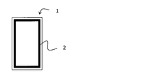
- peel strength shall be measured by the following method. That is, first, the filter medium is arranged on the resin plate so that the base material is located on the resin plate side, and the sample is cut out so as to have a width of 50 mm and used as a test piece. Next, as shown in FIG.
- a resin plate is fixed to one of the grips of the constant-speed extension type tensile tester, and a filter medium is fixed to the other, and the tension is pulled under the condition of a tensile speed of 50 mm / min to obtain the maximum strength. Read and peel strength. Measure with 3 samples and calculate the average value.
- the filter medium for an immersion type filtration cartridge of the present invention can be made into an immersion type filtration cartridge by adhering it to a resin plate by heat or ultrasonic waves. At that time, it is preferable that the resin plate is sandwiched between the two filter media, and the filter layer, the base material, the resin plate, the base material, and the filter layer are arranged in this order. Further, as the resin plate, PP (polypropylene) resin, ABS resin and the like are preferably exemplified. In such a resin plate, a groove may be formed on the surface of the resin plate to serve as a flow path for filtered water. Further, when the filter medium is adhered to the resin plate, it is preferable to adhere the peripheral portion of the filter medium to the resin plate as shown in FIG. 1 instead of the entire surface of the filter medium. Further, a spacer made of a spunbonded non-woven fabric or the like may be partially interposed between the resin plate and the filter medium (base material).
- the suction filtration operation and the intermittent filtration operation in which the suction filtration is stopped and the aeration only operation is repeated alternately are performed.
- the filter medium While suction filtration is being performed, the filter medium is in a state of sticking to the resin plate due to suction pressure, and while suction filtration is stopped, conversely, the filter medium is in a state of swelling away from the resin plate. Therefore, when the filter medium repeatedly swells and adheres to the resin plate, the load tends to concentrate on the adhesive portion between the filter medium and the resin plate, and the filter medium may break or the filter medium may peel off from the resin plate. ..
- the immersion type filtration cartridge of the present invention uses the above-mentioned filter medium for the immersion type filtration cartridge, it not only has excellent collection performance, but also has a low pressure loss, a large processing amount, and excellent fatigue resistance.
- each measurement item in an Example was measured by the following method.
- the fiber length L was measured by utilizing the length measuring function of the SEM.
- Metsuke The basis weight was measured based on JIS P8124 (method for measuring metric basis weight of paper).
- Thickness The thickness of the filter layer and the base material before bonding was measured based on JIS P8118 (method for measuring the thickness and density of paper and paperboard). The measured load was 75 g / cm 2 and the number of samples was 5, and the average value was calculated.
- a cross section of the filter medium was photographed at a magnification of 350 with a scanning electron microscope (SEM), and the thicknesses of the filtered layer and the substrate after bonding were measured. The number of samples was 6, and the average value was calculated.
- Average pore diameter The average pore diameter ( ⁇ m) was measured with a palm polo meter manufactured by PMI. The number of samples was 6, and the average value was calculated.
- Collection performance When the filter medium was cut to a size of 47 mm ⁇ , 50 ppm of humic acid was dispersed in water, and 250 ml was filtered under a reduced pressure of 0.036 MPa, 1 ⁇ m particles were collected due to the difference in the number of 1 ⁇ m particles before and after filtration.
- a resin plate is fixed to one of the grips of the constant-speed extension type tensile tester, and a filter medium is fixed to the other, and the tension is pulled under the condition of a tensile speed of 50 mm / min to obtain the maximum strength. Read and set as peel strength. It was measured with 3 samples and the average value was calculated.
- Example 1 Polypropylene was used as the island component, and modified polyethylene terephthalate obtained by copolymerizing 4% by weight of polyethylene glycol having an average molecular weight of 4000 as the sea component and 9 mol% of 5-sodium sulfoisophthalic acid was used.
- PP polypropylene
- a core-sheath composite fiber having a polypropylene core and a polyethylene sheath was spun by a conventional method to obtain a binder fiber having a single fiber fineness of 0.3 dtex.
- nanofibers 80% by weight
- binder fibers 20% by weight
- wet papermaking was performed with an inclined short net paper machine and dried at 130 ° C. of a Yankee dryer to obtain a wet nonwoven fabric to be a filtration layer. rice field.
- a core-sheath type composite fiber having a polypropylene core and a polyethylene sheath (40% by weight for a single fiber fineness of 3.3 dtex and 60% by weight for a single fiber fineness of 1.7 dtex), and has a thickness of 0.
- a substrate made of a 208 mm wet non-woven fabric was obtained.
- the filter medium was obtained by adhering the filter layer and the base material by heat adhesion.
- the evaluation results are shown in Table 1.
- Table 2 shows the thickness of the filter medium.
- a polypropylene resin plate was prepared, and a groove was formed on the surface of the polypropylene resin plate to serve as a flow path for filtered water.
- the polypropylene resin plate was sandwiched between the two filter media, and the peripheral portion of the filter media was heat-bonded to obtain an immersion type filtration cartridge.
- the filter layer, the base material, the polypropylene resin plate, the base material, and the filter layer were arranged in this order. Further, a spacer (spunbonded non-woven fabric) was partially interposed between the polypropylene resin plate and the base material (filter medium).
- Example 2 In Example 1, the island component of the nanofibers constituting the filtration layer was changed to polyester (polyethylene terephthalate, PET), and unstretched polyester fibers having a fiber diameter of 1.2 ⁇ m and polyester having a single fiber fineness of 0.2 dtex were used as binder fibers.
- polyester polyethylene terephthalate, PET
- unstretched polyester fibers having a fiber diameter of 1.2 ⁇ m and polyester having a single fiber fineness of 0.2 dtex were used as binder fibers.
- PET polyethylene terephthalate, PET
- unstretched polyester fibers Using unstretched fibers, the ratio of nanofibers, unstretched polyester fibers with a fiber diameter of 1.2 ⁇ m and unstretched polyester fibers with a single fiber fineness of 0.2 dtex was 6: 2: 2 in this order. And said.
- a stretched polyester fiber (60% by weight) having a single fiber fineness of 1.7 dtex and a fiber length of 5 mm and an unstretched polyester fiber (40% by weight) having a single fiber fineness of 1.2 dtex and a fiber length of 5 mm, and has a thickness of 0.
- a substrate made of a wet non-woven fabric of .346 mm was obtained.
- the filter medium was obtained by adhering the filter layer and the base material by heat adhesion.
- the evaluation results are shown in Table 1.
- Table 2 shows the thickness of the filter medium.
- an ABS resin plate was prepared, and a groove was formed on the surface of the ABS resin plate to serve as a flow path for filtered water.
- the ABS resin plate was sandwiched between the two filter media, and the peripheral portion of the filter media was heat-bonded to obtain an immersion type filtration cartridge.
- the filter layer, the base material, the ABS resin plate, the base material, and the filter layer were arranged in this order. Further, a spacer (spunbonded non-woven fabric) was partially interposed between the ABS resin plate and the base material (filter medium).
- Example 3 the fiber diameter of the nanofibers constituting the filtration layer is 200 nm, polyester (polyethylene terephthalate, PET) unstretched fiber having a single fiber fineness of 0.2 dtex is used, and the ratio of the nanofiber to the polyester unstretched fiber is 6. : The same as in Example 2 except that it was set to 4. The evaluation results are shown in Table 1. Table 2 shows the thickness of the filter medium.
- an ABS resin plate was prepared, and a groove was formed on the surface of the ABS resin plate to serve as a flow path for filtered water.
- the ABS resin plate was sandwiched between the two filter media, and the peripheral portion of the filter media was heat-bonded to obtain an immersion type filtration cartridge.
- the filter layer, the base material, the ABS resin plate, the base material, and the filter layer were arranged in this order. Further, a spacer (spunbonded non-woven fabric) was partially interposed between the ABS resin plate and the base material (filter medium).
- Example 4 It was the same as in Example 2 except that the thickness of the base material was 0.127 mm in Example 2. The evaluation results are shown in Table 1. Table 2 shows the thickness of the filter medium.
- Example 5 In Example 3, it was the same as in Example 3 except that the fiber diameter of the nanofibers constituting the filtration layer was 700 nm. The evaluation results are shown in Table 1. Table 2 shows the thickness of the filter medium.
- Example 6 In Example 1, it was the same as in Example 1 except that the fiber diameter of the nanofibers constituting the filtration layer was 700 nm. The evaluation results are shown in Table 1. Table 2 shows the thickness of the filter medium.
- a filter medium for an immersion type filtration cartridge and an immersion type filtration cartridge having excellent collection performance, low pressure loss, large processing amount, and excellent fatigue resistance are provided, and their industrial value is high. It is extremely large.
Landscapes
- Chemical & Material Sciences (AREA)
- Chemical Kinetics & Catalysis (AREA)
- Filtering Materials (AREA)
Abstract
La présente invention aborde le problème de la fourniture : un matériau de filtration pour une cartouche de filtration de type à immersion, le matériau de filtration ayant non seulement une performance de collecte exceptionnelle mais également une quantité de traitement élevée avec une faible perte de pression, et ayant également une résistance à la fatigue exceptionnelle ; et une cartouche de filtration de type à immersion. En tant que moyen de solution, la présente invention est un matériau de filtration pour une cartouche de filtration de type à immersion qui comprend une couche de filtration et un matériau de base, des nanofibres ayant un diamètre de fibre de 1000 nm ou moins étant incluses dans la couche de filtration.
Priority Applications (1)
| Application Number | Priority Date | Filing Date | Title |
|---|---|---|---|
| JP2022522545A JPWO2021229925A1 (fr) | 2020-05-12 | 2021-03-25 |
Applications Claiming Priority (2)
| Application Number | Priority Date | Filing Date | Title |
|---|---|---|---|
| JP2020083713 | 2020-05-12 | ||
| JP2020-083713 | 2020-05-12 |
Publications (1)
| Publication Number | Publication Date |
|---|---|
| WO2021229925A1 true WO2021229925A1 (fr) | 2021-11-18 |
Family
ID=78525663
Family Applications (1)
| Application Number | Title | Priority Date | Filing Date |
|---|---|---|---|
| PCT/JP2021/012449 WO2021229925A1 (fr) | 2020-05-12 | 2021-03-25 | Matériau de filtration pour cartouche de filtration de type à immersion, et cartouche de filtration de type à immersion |
Country Status (3)
| Country | Link |
|---|---|
| JP (1) | JPWO2021229925A1 (fr) |
| TW (1) | TW202206171A (fr) |
| WO (1) | WO2021229925A1 (fr) |
Citations (6)
| Publication number | Priority date | Publication date | Assignee | Title |
|---|---|---|---|---|
| JP2001129321A (ja) * | 1999-11-01 | 2001-05-15 | Daicel Chem Ind Ltd | 固液分離装置の運転方法 |
| JP2016159197A (ja) * | 2015-02-27 | 2016-09-05 | 三菱製紙株式会社 | 膜分離活性汚泥処理用半透膜用支持体 |
| JP2017121606A (ja) * | 2016-01-07 | 2017-07-13 | 三菱製紙株式会社 | 膜分離活性汚泥処理用半透膜用支持体及び濾過膜 |
| JP2018114430A (ja) * | 2017-01-16 | 2018-07-26 | 帝人フロンティア株式会社 | 浸漬型濾過カートリッジ用濾材およびその製造方法および浸漬型濾過カートリッジ |
| JP2018192420A (ja) * | 2017-05-17 | 2018-12-06 | 帝人フロンティア株式会社 | 浸漬型濾過カートリッジ用濾材および浸漬型濾過カートリッジ |
| JP2019198833A (ja) * | 2018-05-17 | 2019-11-21 | 帝人フロンティア株式会社 | 浸漬型濾過カートリッジ用濾材および浸漬型濾過カートリッジ |
-
2021
- 2021-03-25 JP JP2022522545A patent/JPWO2021229925A1/ja active Pending
- 2021-03-25 WO PCT/JP2021/012449 patent/WO2021229925A1/fr active Application Filing
- 2021-04-15 TW TW110113507A patent/TW202206171A/zh unknown
Patent Citations (6)
| Publication number | Priority date | Publication date | Assignee | Title |
|---|---|---|---|---|
| JP2001129321A (ja) * | 1999-11-01 | 2001-05-15 | Daicel Chem Ind Ltd | 固液分離装置の運転方法 |
| JP2016159197A (ja) * | 2015-02-27 | 2016-09-05 | 三菱製紙株式会社 | 膜分離活性汚泥処理用半透膜用支持体 |
| JP2017121606A (ja) * | 2016-01-07 | 2017-07-13 | 三菱製紙株式会社 | 膜分離活性汚泥処理用半透膜用支持体及び濾過膜 |
| JP2018114430A (ja) * | 2017-01-16 | 2018-07-26 | 帝人フロンティア株式会社 | 浸漬型濾過カートリッジ用濾材およびその製造方法および浸漬型濾過カートリッジ |
| JP2018192420A (ja) * | 2017-05-17 | 2018-12-06 | 帝人フロンティア株式会社 | 浸漬型濾過カートリッジ用濾材および浸漬型濾過カートリッジ |
| JP2019198833A (ja) * | 2018-05-17 | 2019-11-21 | 帝人フロンティア株式会社 | 浸漬型濾過カートリッジ用濾材および浸漬型濾過カートリッジ |
Also Published As
| Publication number | Publication date |
|---|---|
| TW202206171A (zh) | 2022-02-16 |
| JPWO2021229925A1 (fr) | 2021-11-18 |
Similar Documents
| Publication | Publication Date | Title |
|---|---|---|
| EP2138634B1 (fr) | Nontissé obtenu par voie humide et filtre | |
| JP6695420B2 (ja) | 液体フィルター用ろ材および液体フィルター | |
| JP5607748B2 (ja) | フィルター用多層ろ材およびフィルター | |
| JP6397121B2 (ja) | バグフィルター用ろ過布およびその製造方法およびバグフィルター | |
| KR101441723B1 (ko) | 박엽지 | |
| JP4950472B2 (ja) | 短カットナノファイバーの製造方法 | |
| JP2010070870A (ja) | 不織布の製造方法および不織布および不織布構造体および繊維製品 | |
| JP2014074246A (ja) | 液体ろ過フィルター用湿式不織布および液体ろ過フィルター | |
| JP4994313B2 (ja) | 短カットナノファイバーの製造方法および湿式不織布の製造方法 | |
| JP7028621B2 (ja) | 不織布およびバグフィルター用濾材 | |
| JP6884033B2 (ja) | 浸漬型濾過カートリッジ用濾材および浸漬型濾過カートリッジ | |
| JP2019199668A (ja) | マスク用濾材およびマスク | |
| JP2012092461A (ja) | 薄葉紙 | |
| WO2021229925A1 (fr) | Matériau de filtration pour cartouche de filtration de type à immersion, et cartouche de filtration de type à immersion | |
| JP2012237084A (ja) | フィルター用不織布およびエアーフィルター | |
| JP6829083B2 (ja) | 浸漬型濾過カートリッジ用濾材およびその製造方法および浸漬型濾過カートリッジ | |
| JP2019198833A (ja) | 浸漬型濾過カートリッジ用濾材および浸漬型濾過カートリッジ | |
| JP2023128651A (ja) | 浸漬型濾過カートリッジ用濾材および浸漬型濾過カートリッジ | |
| JP7044526B2 (ja) | 液体フィルター用ろ材 | |
| JP2017170352A (ja) | 燃料フィルター用ろ材およびその製造方法およびガソリンフィルター | |
| JP2022142245A (ja) | 浸漬型濾過カートリッジ用濾材 | |
| JP2008136896A (ja) | フィルターおよびフィルターエレメント | |
| JP2014201847A (ja) | エアレイド不織布および繊維製品 | |
| JP2022094613A (ja) | 不織布、短カット熱接着性繊維およびフィルター | |
| JP2023012165A (ja) | マスク用濾材およびマスク |
Legal Events
| Date | Code | Title | Description |
|---|---|---|---|
| 121 | Ep: the epo has been informed by wipo that ep was designated in this application |
Ref document number: 21804533 Country of ref document: EP Kind code of ref document: A1 |
|
| ENP | Entry into the national phase |
Ref document number: 2022522545 Country of ref document: JP Kind code of ref document: A |
|
| NENP | Non-entry into the national phase |
Ref country code: DE |
|
| 122 | Ep: pct application non-entry in european phase |
Ref document number: 21804533 Country of ref document: EP Kind code of ref document: A1 |