WO2021220447A1 - 劣化診断装置、車上装置、劣化診断システムおよび劣化診断方法 - Google Patents
劣化診断装置、車上装置、劣化診断システムおよび劣化診断方法 Download PDFInfo
- Publication number
- WO2021220447A1 WO2021220447A1 PCT/JP2020/018214 JP2020018214W WO2021220447A1 WO 2021220447 A1 WO2021220447 A1 WO 2021220447A1 JP 2020018214 W JP2020018214 W JP 2020018214W WO 2021220447 A1 WO2021220447 A1 WO 2021220447A1
- Authority
- WO
- WIPO (PCT)
- Prior art keywords
- reception level
- deterioration
- threshold value
- train
- determination
- Prior art date
- Legal status (The legal status is an assumption and is not a legal conclusion. Google has not performed a legal analysis and makes no representation as to the accuracy of the status listed.)
- Ceased
Links
Images




Classifications
-
- B—PERFORMING OPERATIONS; TRANSPORTING
- B60—VEHICLES IN GENERAL
- B60L—PROPULSION OF ELECTRICALLY-PROPELLED VEHICLES; SUPPLYING ELECTRIC POWER FOR AUXILIARY EQUIPMENT OF ELECTRICALLY-PROPELLED VEHICLES; ELECTRODYNAMIC BRAKE SYSTEMS FOR VEHICLES IN GENERAL; MAGNETIC SUSPENSION OR LEVITATION FOR VEHICLES; MONITORING OPERATING VARIABLES OF ELECTRICALLY-PROPELLED VEHICLES; ELECTRIC SAFETY DEVICES FOR ELECTRICALLY-PROPELLED VEHICLES
- B60L3/00—Electric devices on electrically-propelled vehicles for safety purposes; Monitoring operating variables, e.g. speed, deceleration or energy consumption
-
- B—PERFORMING OPERATIONS; TRANSPORTING
- B61—RAILWAYS
- B61L—GUIDING RAILWAY TRAFFIC; ENSURING THE SAFETY OF RAILWAY TRAFFIC
- B61L3/00—Devices along the route for controlling devices on the vehicle or train, e.g. to release brake or to operate a warning signal
- B61L3/02—Devices along the route for controlling devices on the vehicle or train, e.g. to release brake or to operate a warning signal at selected places along the route, e.g. intermittent control simultaneous mechanical and electrical control
- B61L3/08—Devices along the route for controlling devices on the vehicle or train, e.g. to release brake or to operate a warning signal at selected places along the route, e.g. intermittent control simultaneous mechanical and electrical control controlling electrically
- B61L3/12—Devices along the route for controlling devices on the vehicle or train, e.g. to release brake or to operate a warning signal at selected places along the route, e.g. intermittent control simultaneous mechanical and electrical control controlling electrically using magnetic or electrostatic induction; using radio waves
Definitions
- This disclosure relates to a deterioration diagnosis device, an on-board device, a deterioration diagnosis system, and a deterioration diagnosis method for diagnosing deterioration of equipment used for train operation.
- a train equipped with an ATC (Automatic Train Control) on-board device receives an ATC signal flowing on a rail and controls the train to travel according to the speed indicated by the ATC signal, such as the distance from the preceding train. It is carried out.
- ATC Automatic Train Control
- a train equipped with an ATC on-board device causes an abnormality due to deterioration of equipment such as an ATC signal receiver mounted on the train and a ground device on the ground side for transmitting the ATC signal. If this is the case, the ATC signal cannot be received. There is a problem that the train that cannot receive the ATC signal stops operating because the speed cannot be controlled according to the distance from the preceding train.
- the present disclosure has been made in view of the above, and an object of the present disclosure is to obtain a deterioration diagnosis device capable of detecting a sign that a train cannot receive a signal used for train operation.
- the deterioration diagnostic apparatus of the present disclosure receives a signal in a train used for controlling train operation by using a signal received from a structure installed on the ground. It is provided with a determination unit that acquires a reception level measured at times and detects a sign of deterioration of ground equipment or on-board equipment of a train using the reception level and a determination threshold value, and a storage unit that stores the determination threshold value. It is characterized by that.
- the deterioration diagnosis device has an effect of being able to detect a sign that the train cannot receive the signal used for the operation of the train.
- the figure which shows the example of the case where the processing circuit included in the deterioration diagnosis apparatus which concerns on Embodiment 1 is configured by a processor and a memory.
- FIG. 1 is a diagram showing a configuration example of the deterioration diagnosis system 100 according to the first embodiment.
- the deterioration diagnosis system 100 includes an on-board device 10, a data management device 20, and a deterioration diagnosis device 30.
- the train 15 is used to control the operation of the train 15 by using signals received from the ground element 40, the rail 50, and the like installed on the ground.
- the train 15 may be composed of a plurality of vehicles, or may be a single train composed of one vehicle as shown in FIG.
- the train 15 includes an on-board device 10, an on-board element 13, and a power receiver 14.
- the on-board child 13 receives a signal including information such as the position information of the ground element 40 from the ground element 40 installed on the ground.
- the on-board element 13 may send and receive signals to and from the ground element 40.
- the power receiver 14 receives a signal from the rail 50 installed on the ground, including information such as speed information indicating the speed limit for the train 15.
- the train 15 may have the on-board device 10 having the function of the ATC on-board device, or may have an ATC on-board device (not shown) separately from the on-board device 10.
- the on-board device 10 includes a measuring unit 11 and a vehicle information management device 12.
- the measuring unit 11 extracts information necessary for controlling the operation of the train 15 from the signal received by the on-board element 13 from the ground element 40 and the signal received by the power receiver 14 from the rail 50.
- the information necessary for controlling the operation of the train 15 includes the position information of the ground element 40, the speed information indicating the speed limit for the train 15, and the like.
- the measuring unit 11 measures the reception level when the on-board element 13 receives the signal from the ground element 40 on the train 15, and determines the reception level when the power receiver 14 receives the signal from the rail 50. taking measurement.
- the reception level is, for example, electric field strength, SNR (Signal to Noise Ratio), or the like.
- SNR Synignal to Noise Ratio
- the vehicle information management device 12 manages the position of the train 15.
- the vehicle information management device 12 is, for example, a train 15 obtained from a speed generator (not shown) or the like at a position indicated by the position information of the ground element 40, which is information included in the signal received from the ground element 40 by the on-board element 13.
- the position of the train 15 can be calculated by adding the mileage calculated from the speed information and the traveling time information.
- the vehicle information management device 12 may manage the position of the train 15 by using GPS (Global Positioning System) or the like.
- the vehicle information management device 12 is, for example, a device such as TIMS (Train Integrated Management System).
- the vehicle information management device 12 transmits the reception level measured by the measurement unit 11 and the position information of the train 15 to the deterioration diagnosis device 30 via the data management device 20 by wireless communication.
- the data management device 20 receives the reception level and the position information of the train 15 transmitted from the vehicle information management device 12 of the on-board device 10 mounted on the train 15 by wireless communication.
- the data management device 20 outputs the received reception level and the position information of the train 15 to the deterioration diagnosis device 30.
- the deterioration diagnosis device 30 includes a determination unit 31 and a storage unit 32.
- the determination unit 31 acquires the reception level measured when the signal is received by the train 15 from the on-board device 10 via the data management device 20.
- the determination unit 31 detects the sign of deterioration of the ground equipment or the on-board equipment of the train 15 by using the reception level and the determination threshold value for detecting the sign of deterioration of the ground equipment or the on-board equipment of the train 15. .
- the ground equipment is a ground device such as a communication device (not shown) that generates signals transmitted from the ground element 40, the rail 50, the ground element 40, and the rail 50.
- the on-board equipment of the train 15 is an on-board child 13, a power receiver 14, and the like.
- the determination unit 31 detects that the ground equipment or the on-board equipment of the train 15 has not deteriorated, but the state before the deterioration has occurred as a sign of deterioration. Specifically, the determination unit 31 compares the reception level with the determination threshold. When the reception level becomes equal to or lower than the determination threshold value, the determination unit 31 determines that it has detected a sign of deterioration of the ground equipment or the on-board equipment of the train 15. The detailed operation of the determination unit 31 will be described later.
- the storage unit 32 stores the determination threshold value. Further, the storage unit 32 stores the minimum operation level threshold value for determining whether or not a signal is transmitted from the ground element 40 or the rail 50. For example, the user who uses the deterioration diagnosis system 100 stores the determination threshold value and the minimum operation level threshold value in the storage unit 32 in advance. The determination threshold value may be changed as appropriate.
- the ground element 40 transmits a signal including position information indicating the position where the ground element 40 is installed.
- the ground element 40 may transmit a signal including identification information that can identify the ground element 40 instead of the position information.
- the rail 50 transmits a signal including speed information indicating a speed limit for the train 15 according to the distance from the preceding train traveling in front of the train 15 in the traveling direction.
- the ground element 40 and the rail 50 are structures installed on the ground.
- the operation in which the deterioration diagnosis device 30 detects a sign of deterioration of the ground equipment or the on-board equipment of the train 15 will be described.
- the train 15 receives a signal from the rail 50 will be described.
- the same operation is performed when the train 15 receives a signal from the ground element 40.
- the system for operating the train 15 divides the section in which the train 15 travels into a plurality of block sections.
- the rail 50 in each block section transmits a signal including speed information indicating a speed limit with respect to the train 15, which is a speed corresponding to a distance from a preceding train traveling in front of the train 15 in the traveling direction.
- the rail 50 transmits a signal including speed information in each block section in units of block sections.
- the signal transmitted from the rail 50 is output from the rail 50 on which the train 15 travels for each block section. That is, the system for operating the train 15 is provided with equipment capable of transmitting different signals for each block section as ground equipment. Therefore, as shown in FIGS.
- the deterioration diagnosis device 30 of the ground equipment or the train 15 depends on whether the reception level is lowered in all the block sections or the reception level is lowered in a specific block section. It is possible to detect signs of deterioration of on-board equipment.
- FIG. 2 is a diagram showing a transition of a change in the reception level when the on-board equipment of the train 15 is in a state showing a sign of deterioration in the deterioration diagnosis system 100 according to the first embodiment.
- the horizontal axis indicates the running position of the train 15, and the vertical axis indicates the signal reception level of the train 15.
- the Z train 15 has a good reception level at the start of business. In general, the performance of equipment deteriorates due to aging. Even in the Z train 15, it is expected that the reception performance of the power receiver 14 and the like will deteriorate due to aging. As shown in FIG.
- the reception level of the Z train 15 is lower than that at the start of business in all the block sections T1 year after the start of business. As shown in FIG. 2C, the reception level of the Z train 15 is further lowered in all the block sections T2 years after the start of business. It should be noted that T2> T1.
- the deterioration diagnosis device 30 determines that the on-board equipment provided in the Z train 15 such as the power receiver 14 shows a sign of deterioration. be able to. Specifically, the determination unit 31 of the deterioration diagnosis device 30 deteriorates the on-board equipment of the Z train 15 when the reception level drops below the determination threshold value in a plurality of block sections. It is determined that a sign has been detected.
- FIG. 3 is a diagram showing a transition of a change in the reception level when the ground equipment in the deterioration diagnosis system 100 according to the first embodiment is in a state showing a sign of deterioration.
- the horizontal axis represents the running position of the train 15, and the vertical axis represents the signal reception level of the train 15.
- the trains 15 of the A to Z trains have a good reception level at the start of business. In general, the performance of equipment deteriorates due to aging.
- the reception level of the trains 15 of the A to Z trains is lower than that at the start of business in a specific block section T1 year after the start of business.
- the reception level of the trains 15 of the A to Z trains further decreases in a specific block section two years after the start of business. It should be noted that T2> T1.
- the deterioration diagnosis device 30 is a sign of deterioration of the on-board equipment of all the A to Z trains 15. Is detected, and it is judged that the possibility that the reception level drops only in a specific block section is low.
- the deterioration diagnosis device 30 can determine that the ground equipment in a specific block section, for example, a communication device, which transmits a signal from the rail 50 toward the A to Z formation, is showing a sign of deterioration.
- the determination unit 31 of the deterioration diagnosis device 30 detects a sign of deterioration of the ground equipment in the specific block section when the reception level drops below the determination threshold in the specific block section. It is determined that it has been done.
- the reception level is lowered in some places, which indicates the boundary of the block section.
- the rail 50 has a region where no signal flows at the boundary of the block section. That is, the boundary of the block section becomes a no-signal state.
- the signal reception level is lowered in the train 15 even if the on-board equipment and the ground equipment do not show signs of deterioration. Therefore, the deterioration diagnosis device 30 does not use the reception level measured by the train 15 while the train 15 is traveling on the boundary of the block section for determining the sign of deterioration of the on-board equipment or the ground equipment.
- FIG. 4 is a flowchart showing the operation of the on-board device 10 according to the first embodiment.
- the measuring unit 11 measures the reception level when the signal transmitted from the rail 50 is received by the power receiver 14 (step S11).
- the measuring unit 11 outputs the measured reception level information to the vehicle information management device 12.
- the vehicle information management device 12 transmits the reception level measured by the measurement unit 11 and the position information of the train 15 to the deterioration diagnosis device 30 via the data management device 20 (step S12).
- the on-board device 10 compares the reception level 60 with the minimum operation level threshold value 61.
- the on-board device 10 instructs the operation of the emergency brake (step S14).
- the first period is a period longer than the period in which the reception level 60 momentarily drops at the boundary of the block section in a good condition in which the on-board equipment and the ground equipment of the train 15 show no sign of deterioration.
- the reception level 60 is larger than the minimum operation level threshold value 61, or when the reception level 60 is equal to or less than the minimum operation level threshold value 61 but does not continue for the specified first period (step S13: No), the on-board device.
- the on-board device 10 ends the operation.
- the case where the on-board device 10 has the function of the ATC on-board device is described as an example, but when the train 15 is provided with the ATC on-board device (not shown) in addition to the on-board device 10.
- the ATC on-board device may perform the operations of steps S13 and S14.
- the on-board device 10 periodically repeats the operation shown in FIG.
- FIG. 5 is a flowchart showing the operation of the deterioration diagnosis device 30 according to the first embodiment.
- the determination unit 31 acquires the reception level and the position information of the train 15 from the on-board device 10 via the data management device 20 (step S21).
- the determination unit 31 compares the reception level with the minimum operation level threshold value and the determination threshold value, as will be described later.
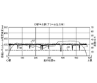
- FIG. 6 is a diagram showing an image of the determination process in the determination unit 31 of the deterioration diagnosis device 30 according to the first embodiment.
- the horizontal axis shows the running position of the train 15 from the ⁇ station to the ⁇ station.
- the vertical axis on the left side indicates the magnitude of the reception level 60
- the vertical axis on the right side indicates the speed V of the train 15.
- the vertical axis on the left side also shows the magnitudes of the minimum operation level threshold value 61 and the determination threshold value 62.
- the magnitude of the reception level 60 is represented by a value converted into a current flowing through the rail 50 in FIG. 6, it may be represented by a voltage value as in FIGS. 2 and 3.
- the determination unit 31 since the signal does not flow on the rail 50 at the boundary of the block section, the determination unit 31 does not make a judgment at the boundary of the block section.
- the determination unit 31 may continuously compare the reception level 60 with the minimum operation level threshold value 61 and the determination threshold value 62, or remove the boundary of the block section, that is, from the specified timing. It may be done in the specified period.
- the determination unit 31 continuously compares the reception level 60 with the minimum operation level threshold value 61 and the determination threshold value 62, the determination unit 31 does not determine the reception level 60 that momentarily drops at the boundary of the block section. do.
- the determination unit 31 compares the reception level 60 with the minimum operation level threshold value 61 and the determination threshold value 62 from a specified timing to a specified period, for example, from the timing when the train 15 travels in the center of each block section.
- the reception level 60 measured when traveling in the specified period is subject to the determination.
- the specified period may vary depending on the speed V of the train 15.
- the determination unit 31 can recognize the temporal transition of the fluctuation of the reception level 60 at the timing of acquiring the information of the reception level 60 from the on-board device 10 via the data management device 20. Further, the determination unit 31 also acquires information on the speed V of the train 15 from the on-board device 10 via the data management device 20, and divides the range of the traveling position of the train 15 shown in FIG. 6 by the speed V. , The period required for the train 15 to travel the distance to the traveling position can be calculated. The determination unit 31 calculates the period required for the train 15 to travel the distance to the traveling position in a certain range shown in FIG. 6, and thus the time of fluctuation of the reception level 60 in the range of the distance to the traveling position. It is possible to recognize the transition.
- the determination unit 31 reads the determination threshold value 62 from the storage unit 32 and compares the reception level 60 with the determination threshold value 62. When the reception level 60 is the determination threshold value 62 or less and continues for the specified second period (step S22: Yes), the determination unit 31 asks whether the reception level 60 is the determination threshold value 62 or less in the specific block section. , Or, it is determined whether the reception level 60 is equal to or less than the determination threshold value 62 in the plurality of block sections.
- the second period is longer than the period in which the reception level 60 momentarily drops at the boundary of the block section in a good condition where the on-board equipment and the ground equipment of the train 15 show no sign of deterioration.
- the second period may vary depending on the speed V of the train 15.
- the determination unit 31 When the reception level 60 is equal to or lower than the determination threshold value 62 in the specific block section (step S23: Yes), the determination unit 31 indicates that the system operating the train 15 has detected a sign of deterioration of the ground equipment. Output an alarm (step S24). As an alarm, the determination unit 31 displays, for example, that a sign of deterioration of the ground equipment has been detected on a display unit (not shown) included in the deterioration diagnosis device 30. As an alarm, the determination unit 31 may make the user recognize that a sign of deterioration of the ground equipment has been detected by using an LED (Light Emitting Diode), a speaker, or the like (not shown) included in the deterioration diagnosis device 30.
- LED Light Emitting Diode
- the determination unit 31 outputs an alarm in the following description.
- the reception level 60 is equal to or lower than the determination threshold value 62 in a plurality of block sections (step S23: No)
- the determination unit 31 detects a sign of deterioration of the on-board equipment of the train 15 in the system for operating the train 15.
- An alarm indicating that the operation has been performed is output (step S25).
- the user who confirms the alarm recognizes that either the ground equipment or the on-board equipment of the train 15 shows a sign of deterioration, and can take measures such as inspection, repair, and replacement of the equipment. can.
- the determination unit 31 When the reception level 60 is larger than the determination threshold value 62, or when the reception level 60 is equal to or less than the determination threshold value 62 but does not continue for the specified second period (step S22: No), the determination unit 31 operates. finish. The determination unit 31 repeatedly performs the operation shown in FIG. 5 continuously or from a specified timing to a specified period.
- FIG. 7 is a diagram showing an example of a reception level 60 when the deterioration diagnosis device 30 according to the first embodiment detects a sign of deterioration of ground equipment.
- the determination unit 31 of the deterioration diagnosis device 30 detects a sign of deterioration of the ground equipment in the specific block section. judge.
- FIG. 8 is a diagram showing an example of a reception level 60 when the deterioration diagnosis device 30 according to the first embodiment detects a sign of deterioration of the on-board equipment of the train 15. As shown in FIG.
- the determination unit 31 of the deterioration diagnosis device 30 is a sign of deterioration of the on-board equipment of the train 15 when a plurality of block sections, that is, the reception level 60 as a whole is equal to or less than the determination threshold value 62. Is determined to have been detected.
- the deterioration diagnosis device 30 may be mounted on the train 15. In this case, the deterioration diagnosis system 100 may delete the data management device 20 so that the vehicle information management device 12 of the on-board device 10 and the deterioration diagnosis device 30 directly communicate with each other. Even when mounted on the train 15, the deterioration diagnosis device 30 can detect a sign of deterioration of the on-board equipment of the train 15 with the same accuracy as when it is installed on the ground. Further, even when mounted on the train 15, the accuracy of the deterioration diagnosis device 30 is lower than that when it is installed on the ground, but by performing the determination a plurality of times, a sign of deterioration of the ground equipment is detected. can do.
- the storage unit 32 is a memory.
- the determination unit 31 is realized by a processing circuit.
- the processing circuit may be a processor and memory for executing a program stored in the memory, or may be dedicated hardware.
- FIG. 9 is a diagram showing an example in which the processing circuit included in the deterioration diagnosis device 30 according to the first embodiment is configured by a processor and a memory.
- the processing circuit is composed of the processor 91 and the memory 92, each function of the processing circuit of the deterioration diagnosis device 30 is realized by software, firmware, or a combination of software and firmware.
- the software or firmware is written as a program and stored in the memory 92.
- each function is realized by the processor 91 reading and executing the program stored in the memory 92. That is, the processing circuit includes a memory 92 for storing a program in which the processing of the deterioration diagnosis device 30 is eventually executed. It can also be said that these programs cause the computer to execute the procedure and method of the deterioration diagnosis device 30.
- the processor 91 may be a CPU (Central Processing Unit), a processing device, an arithmetic unit, a microprocessor, a microcomputer, a DSP (Digital Signal Processor), or the like.
- the memory 92 includes, for example, non-volatile or volatile such as RAM (Random Access Memory), ROM (Read Only Memory), flash memory, EPROM (Erasable Programmable ROM), EEPROM (registered trademark) (Electrically EPROM).
- RAM Random Access Memory
- ROM Read Only Memory
- flash memory EPROM (Erasable Programmable ROM), EEPROM (registered trademark) (Electrically EPROM).
- Semiconductor memory magnetic disk, flexible disk, optical disk, compact disk, mini disk, DVD (Digital Versatile Disc), etc. are applicable.
- FIG. 10 is a diagram showing an example in which the processing circuit included in the deterioration diagnosis device 30 according to the first embodiment is configured by dedicated hardware.
- the processing circuit is composed of dedicated hardware
- the processing circuit 93 shown in FIG. 10 includes, for example, a single circuit, a composite circuit, a programmed processor, a parallel programmed processor, an ASIC (Application Specific Integrated Circuit), and the like. FPGA (Field Programmable Gate Array) or a combination of these is applicable.
- Each function of the deterioration diagnosis device 30 may be realized by the processing circuit 93 for each function, or each function may be collectively realized by the processing circuit 93.
- a part may be realized by dedicated hardware and a part may be realized by software or firmware.
- the processing circuit can realize each of the above-mentioned functions by the dedicated hardware, software, firmware, or a combination thereof.
- the measuring unit 11 is an interface capable of receiving a signal.
- the vehicle information management device 12 is realized by a processing circuit.
- the processing circuit may be a processor and memory for executing a program stored in the memory, or may be dedicated hardware.
- the deterioration diagnosis device 30 is measured when a signal is received from the on-board device 10 by the train 15 via the data management device 20.
- the information of the reception level 60 is acquired, and the reception level 60 and the determination threshold value 62 are used to detect a sign of deterioration of the ground equipment or the on-board equipment of the train 15.
- the reception level 60 becomes the determination threshold value 62 or less in a plurality of block sections
- the deterioration diagnosis device 30 determines that it has detected a sign of deterioration of the on-board equipment, and determines that the reception level is detected in a specific block section.
- the deterioration diagnosis device 30 can detect a sign that the train 15 cannot receive the signal used for the operation of the train 15. As a result, the user can recognize that either the ground equipment or the on-board equipment of the train 15 shows a sign of deterioration, and can take measures such as inspection, repair, and replacement of the equipment. As a result, in the system for operating the train 15, the ground equipment or the on-board equipment of the train 15 deteriorates during the operation of the train 15, the train 15 cannot receive the signal, and the operation of the train 15 is stopped. Can be avoided.
- Embodiment 2 the determination unit 31 of the deterioration diagnosis device 30 considers a no-signal state at the boundary of the block section when the period during which the reception level 60 becomes the minimum operation level threshold value 61 or less is the first period or less. Therefore, it was considered that the minimum operation level threshold value was not equal to or less than 61.
- the determination unit 31 of the deterioration diagnosis device 30 outputs an alarm when the period during which the reception level 60 becomes the minimum operation level threshold value 61 or less is the third period or more, which is shorter than the first period.
- FIG. 11 is a diagram showing an image of the determination process in the determination unit 31 of the deterioration diagnosis device 30 according to the second embodiment.
- the horizontal axis represents time and the vertical axis represents reception level 60.
- the determination unit 31 of the deterioration diagnosis device 30 indicates that the period during which the reception level 60 is equal to or less than the minimum operation level threshold value 61 is shorter than the first period 63, but is longer than the defined third period 64. If it is too long, an alarm is output.
- the third period 64 is, for example, a period in which a margin is provided for a period in which the reception level 60 drops at the boundary of the block section when both the ground equipment and the on-board equipment of the train 15 are in the state at the start of business. do.
- the determination unit 31 detects a sign of deterioration of either the ground equipment or the on-board equipment of the train 15. It presumes that there is a possibility of this and outputs an alarm. Further, the determination unit 31 may detect a sign of deterioration of the ground equipment when the period during which the reception level 60 becomes the minimum operation level threshold value 61 or less is longer than the third period 64 for the plurality of trains 15. It is possible to presume that there is an alarm and output an alarm.
- the determination unit 31 compares the reception level 60 with the minimum operation level threshold value 61, and the period during which the reception level 60 becomes the minimum operation level threshold value 61 or less is a defined period of 64 or more. In this case, an alarm indicating that the period in which the reception level 60 becomes the minimum operation level threshold value 61 or less is the third period 64 or more, which is the specified period, is output. As a result, the user who has confirmed the alarm can recognize that either the ground equipment or the on-board equipment of the train 15 may show a sign of deterioration, and can perform maintenance or the like.
- the determination unit 31 indicates that the ground equipment is a sign of deterioration when the reception level 60 becomes the minimum operation level threshold value 61 or less for the plurality of trains 15 and becomes the third period 64 or more, which is the defined period.
- An alarm may be output indicating that there is a possibility.
- the deterioration diagnosis device 30 compares the reception level 60 with the minimum operation level threshold value 61, and the reception level 60 is equal to or less than the minimum operation level threshold value 61. An alarm is output when the third period 64 or more, which is the specified period, is reached. As a result, the deterioration diagnosis device 30 can show the user in advance the ground equipment that may detect a sign of deterioration or the on-board equipment of the train 15.
- the determination unit 31 of the deterioration diagnosis device 30 outputs an alarm when the period during which the reception level 60 becomes the determination threshold value 62 or less is shorter than the second period but longer than the specified fourth period. May be good. Specifically, in the operation of the flowchart shown in FIG. 5, in the case of step S22: No, the determination unit 31 further determines whether or not the reception level 60 is equal to or less than the determination threshold value 62 and continues for the specified fourth period. To confirm. When the reception level 60 is equal to or less than the determination threshold value 62 and continues for the specified fourth period, the determination unit 31 performs the same operation as the operations from step S23 to step S25. As a result, the determination unit 31 can indicate to the user in advance the ground equipment that may detect a sign of deterioration or the on-board equipment of the train 15.
- Embodiment 3 In the first embodiment, the determination unit 31 of the deterioration diagnosis device 30 compares the reception level 60 with one determination threshold value 62. In the third embodiment, the determination unit 31 of the deterioration diagnosis device 30 compares the reception level 60 with the plurality of determination threshold values.
- FIG. 12 is a diagram showing an image of the determination process in the determination unit 31 of the deterioration diagnosis device 30 according to the third embodiment.
- FIG. 12 shows the image of the determination process of the first embodiment, in which the determination threshold value 62 is set to the first determination threshold value 65 and the second determination threshold value 66 is added to FIGS. 6 to 8.
- the determination unit 31 of the deterioration diagnosis device 30 deteriorates the ground equipment in a specific block section when the reception level 60 is larger than the first determination threshold value 65 but the reception level 60 is equal to or less than the second determination threshold value 66. Outputs an alarm indicating that there is a tendency.
- the user who has confirmed the alarm can perform maintenance and the like on the ground equipment in a specific block section more intensively than the ground equipment in another block section.
- the storage unit 32 stores a plurality of determination threshold values as determination threshold values.
- the determination unit 31 compares the reception level 60 with the plurality of determination thresholds, and outputs an alarm based on each determination threshold.
- the determination unit 31 of the deterioration diagnosis device 30 outputs an alarm as the on-board equipment of the train 15 tends to deteriorate when the reception level 60 becomes the second determination threshold value 66 or less in a plurality of block sections. be able to.
- the deterioration diagnosis device 30 compares the reception level 60 with a plurality of judgment threshold values and outputs an alarm based on each judgment threshold value. bottom. As a result, the deterioration diagnosis device 30 can output an alarm according to the current state of the reception level 60 to the user.
- the configuration shown in the above embodiments is an example, and can be combined with another known technique, can be combined with each other, and does not deviate from the gist. It is also possible to omit or change a part of the configuration.
Landscapes
- Engineering & Computer Science (AREA)
- Mechanical Engineering (AREA)
- Life Sciences & Earth Sciences (AREA)
- Sustainable Development (AREA)
- Sustainable Energy (AREA)
- Power Engineering (AREA)
- Transportation (AREA)
- Train Traffic Observation, Control, And Security (AREA)
- Electric Propulsion And Braking For Vehicles (AREA)
Priority Applications (2)
| Application Number | Priority Date | Filing Date | Title |
|---|---|---|---|
| PCT/JP2020/018214 WO2021220447A1 (ja) | 2020-04-30 | 2020-04-30 | 劣化診断装置、車上装置、劣化診断システムおよび劣化診断方法 |
| JP2022518527A JP7334342B2 (ja) | 2020-04-30 | 2020-04-30 | 劣化診断装置および劣化診断方法 |
Applications Claiming Priority (1)
| Application Number | Priority Date | Filing Date | Title |
|---|---|---|---|
| PCT/JP2020/018214 WO2021220447A1 (ja) | 2020-04-30 | 2020-04-30 | 劣化診断装置、車上装置、劣化診断システムおよび劣化診断方法 |
Publications (1)
| Publication Number | Publication Date |
|---|---|
| WO2021220447A1 true WO2021220447A1 (ja) | 2021-11-04 |
Family
ID=78331877
Family Applications (1)
| Application Number | Title | Priority Date | Filing Date |
|---|---|---|---|
| PCT/JP2020/018214 Ceased WO2021220447A1 (ja) | 2020-04-30 | 2020-04-30 | 劣化診断装置、車上装置、劣化診断システムおよび劣化診断方法 |
Country Status (2)
| Country | Link |
|---|---|
| JP (1) | JP7334342B2 (https=) |
| WO (1) | WO2021220447A1 (https=) |
Cited By (1)
| Publication number | Priority date | Publication date | Assignee | Title |
|---|---|---|---|---|
| JP2023082249A (ja) * | 2021-12-02 | 2023-06-14 | 日本信号株式会社 | 地上子の検査装置 |
Citations (4)
| Publication number | Priority date | Publication date | Assignee | Title |
|---|---|---|---|---|
| JPH1095337A (ja) * | 1996-09-20 | 1998-04-14 | Kyosan Electric Mfg Co Ltd | Atc装置の送信器故障検知装置 |
| JP2008178230A (ja) * | 2007-01-19 | 2008-07-31 | Mitsubishi Electric Corp | 自動列車制御装置 |
| JP2010013041A (ja) * | 2008-07-07 | 2010-01-21 | Hitachi Ltd | 無線通信を用いた列車制御システム |
| JP2013153611A (ja) * | 2012-01-25 | 2013-08-08 | Toshiba Corp | 列車制御システム |
Family Cites Families (3)
| Publication number | Priority date | Publication date | Assignee | Title |
|---|---|---|---|---|
| JPS55117401A (en) * | 1979-02-28 | 1980-09-09 | Mitsubishi Electric Corp | Detecting method of fault in atc system |
| JP2016002931A (ja) * | 2014-06-18 | 2016-01-12 | 株式会社日立製作所 | 軌道回路用送信器及びその故障検知方法 |
| JP6882909B2 (ja) * | 2017-02-17 | 2021-06-02 | 株式会社日立製作所 | 診断システム及び診断方法 |
-
2020
- 2020-04-30 JP JP2022518527A patent/JP7334342B2/ja active Active
- 2020-04-30 WO PCT/JP2020/018214 patent/WO2021220447A1/ja not_active Ceased
Patent Citations (4)
| Publication number | Priority date | Publication date | Assignee | Title |
|---|---|---|---|---|
| JPH1095337A (ja) * | 1996-09-20 | 1998-04-14 | Kyosan Electric Mfg Co Ltd | Atc装置の送信器故障検知装置 |
| JP2008178230A (ja) * | 2007-01-19 | 2008-07-31 | Mitsubishi Electric Corp | 自動列車制御装置 |
| JP2010013041A (ja) * | 2008-07-07 | 2010-01-21 | Hitachi Ltd | 無線通信を用いた列車制御システム |
| JP2013153611A (ja) * | 2012-01-25 | 2013-08-08 | Toshiba Corp | 列車制御システム |
Cited By (2)
| Publication number | Priority date | Publication date | Assignee | Title |
|---|---|---|---|---|
| JP2023082249A (ja) * | 2021-12-02 | 2023-06-14 | 日本信号株式会社 | 地上子の検査装置 |
| JP7788057B2 (ja) | 2021-12-02 | 2025-12-18 | 日本信号株式会社 | 地上子の検査装置 |
Also Published As
| Publication number | Publication date |
|---|---|
| JP7334342B2 (ja) | 2023-08-28 |
| JPWO2021220447A1 (https=) | 2021-11-04 |
Similar Documents
| Publication | Publication Date | Title |
|---|---|---|
| US10459001B2 (en) | Method for determining at least one speed in a rail vehicle | |
| KR101488420B1 (ko) | 무선 및 자가발전 센서를 이용한 철도 차량 모니터링 시스템 및 방법 | |
| RU2542784C2 (ru) | Способ и электронное устройство для контроля состояния деталей рельсовых транспортных средств | |
| JP4662792B2 (ja) | 車輪の車輪特性量を監視するための方法および監視装置 | |
| WO2021220447A1 (ja) | 劣化診断装置、車上装置、劣化診断システムおよび劣化診断方法 | |
| JP2017163623A (ja) | 列車制御システム | |
| BR102020001702A2 (pt) | Sistema de detecção de trem, seção de via de trem e método de detecção | |
| CN116968782A (zh) | 一种列车完整性监测系统及监测方法 | |
| JP2011011715A (ja) | 異常原因特定装置、異常原因特定システム、および異常原因特定方法 | |
| JP6882909B2 (ja) | 診断システム及び診断方法 | |
| US10829097B2 (en) | Speed control device | |
| JP2013100111A (ja) | 異常原因特定装置、異常原因特定システム、および異常原因特定方法 | |
| KR101019127B1 (ko) | 차량 속도 측정 장치 및 그 방법 | |
| EP4335721A1 (en) | Data communication system, computer-implemented method for data communication in a railway network, computer program and non-volatile data carrier | |
| KR101386659B1 (ko) | 자동차의 중앙 처리 장치와 타이어 압력 센서 사이의 신호 교환 방법 | |
| JP2005349945A (ja) | 列車制御装置 | |
| CN111071303A (zh) | 列车控制方法、装置、系统和计算机联锁设备 | |
| WO2022054290A1 (ja) | 中央装置および故障レベル変更方法 | |
| JP4125143B2 (ja) | 通信波式定位置停止制御方法 | |
| US12606221B2 (en) | Data communication system, computer-implemented method for data communication in a railway network, computer program and non-volatile data carrier | |
| JP2006190066A (ja) | 異常交通流検出装置及び異常交通流検出方法 | |
| KR102423140B1 (ko) | 차량검지 시스템 및 그의 제어 방법 | |
| EP3360748A1 (en) | Driving assistance of collaborative type | |
| JP5640127B1 (ja) | 車上装置 | |
| JP2802235B2 (ja) | 故障予知検出装置 |
Legal Events
| Date | Code | Title | Description |
|---|---|---|---|
| 121 | Ep: the epo has been informed by wipo that ep was designated in this application |
Ref document number: 20933469 Country of ref document: EP Kind code of ref document: A1 |
|
| ENP | Entry into the national phase |
Ref document number: 2022518527 Country of ref document: JP Kind code of ref document: A |
|
| NENP | Non-entry into the national phase |
Ref country code: DE |
|
| 122 | Ep: pct application non-entry in european phase |
Ref document number: 20933469 Country of ref document: EP Kind code of ref document: A1 |