WO2021220447A1 - Deterioration diagnostic device, on-vehicle device, deterioration diagnostic system, and deterioration diagnostic method - Google Patents
Deterioration diagnostic device, on-vehicle device, deterioration diagnostic system, and deterioration diagnostic method Download PDFInfo
- Publication number
- WO2021220447A1 WO2021220447A1 PCT/JP2020/018214 JP2020018214W WO2021220447A1 WO 2021220447 A1 WO2021220447 A1 WO 2021220447A1 JP 2020018214 W JP2020018214 W JP 2020018214W WO 2021220447 A1 WO2021220447 A1 WO 2021220447A1
- Authority
- WO
- WIPO (PCT)
- Prior art keywords
- reception level
- deterioration
- threshold value
- train
- determination
- Prior art date
Links
Images


Classifications
-
- B—PERFORMING OPERATIONS; TRANSPORTING
- B60—VEHICLES IN GENERAL
- B60L—PROPULSION OF ELECTRICALLY-PROPELLED VEHICLES; SUPPLYING ELECTRIC POWER FOR AUXILIARY EQUIPMENT OF ELECTRICALLY-PROPELLED VEHICLES; ELECTRODYNAMIC BRAKE SYSTEMS FOR VEHICLES IN GENERAL; MAGNETIC SUSPENSION OR LEVITATION FOR VEHICLES; MONITORING OPERATING VARIABLES OF ELECTRICALLY-PROPELLED VEHICLES; ELECTRIC SAFETY DEVICES FOR ELECTRICALLY-PROPELLED VEHICLES
- B60L3/00—Electric devices on electrically-propelled vehicles for safety purposes; Monitoring operating variables, e.g. speed, deceleration or energy consumption
-
- B—PERFORMING OPERATIONS; TRANSPORTING
- B61—RAILWAYS
- B61L—GUIDING RAILWAY TRAFFIC; ENSURING THE SAFETY OF RAILWAY TRAFFIC
- B61L3/00—Devices along the route for controlling devices on the vehicle or vehicle train, e.g. to release brake, to operate a warning signal
- B61L3/02—Devices along the route for controlling devices on the vehicle or vehicle train, e.g. to release brake, to operate a warning signal at selected places along the route, e.g. intermittent control simultaneous mechanical and electrical control
- B61L3/08—Devices along the route for controlling devices on the vehicle or vehicle train, e.g. to release brake, to operate a warning signal at selected places along the route, e.g. intermittent control simultaneous mechanical and electrical control controlling electrically
- B61L3/12—Devices along the route for controlling devices on the vehicle or vehicle train, e.g. to release brake, to operate a warning signal at selected places along the route, e.g. intermittent control simultaneous mechanical and electrical control controlling electrically using magnetic or electrostatic induction; using radio waves
Definitions
- This disclosure relates to a deterioration diagnosis device, an on-board device, a deterioration diagnosis system, and a deterioration diagnosis method for diagnosing deterioration of equipment used for train operation.
- a train equipped with an ATC (Automatic Train Control) on-board device receives an ATC signal flowing on a rail and controls the train to travel according to the speed indicated by the ATC signal, such as the distance from the preceding train. It is carried out.
- ATC Automatic Train Control
- a train equipped with an ATC on-board device causes an abnormality due to deterioration of equipment such as an ATC signal receiver mounted on the train and a ground device on the ground side for transmitting the ATC signal. If this is the case, the ATC signal cannot be received. There is a problem that the train that cannot receive the ATC signal stops operating because the speed cannot be controlled according to the distance from the preceding train.
- the present disclosure has been made in view of the above, and an object of the present disclosure is to obtain a deterioration diagnosis device capable of detecting a sign that a train cannot receive a signal used for train operation.
- the deterioration diagnostic apparatus of the present disclosure receives a signal in a train used for controlling train operation by using a signal received from a structure installed on the ground. It is provided with a determination unit that acquires a reception level measured at times and detects a sign of deterioration of ground equipment or on-board equipment of a train using the reception level and a determination threshold value, and a storage unit that stores the determination threshold value. It is characterized by that.
- the deterioration diagnosis device has an effect of being able to detect a sign that the train cannot receive the signal used for the operation of the train.
- the figure which shows the example of the case where the processing circuit included in the deterioration diagnosis apparatus which concerns on Embodiment 1 is configured by a processor and a memory.
- FIG. 1 is a diagram showing a configuration example of the deterioration diagnosis system 100 according to the first embodiment.
- the deterioration diagnosis system 100 includes an on-board device 10, a data management device 20, and a deterioration diagnosis device 30.
- the train 15 is used to control the operation of the train 15 by using signals received from the ground element 40, the rail 50, and the like installed on the ground.
- the train 15 may be composed of a plurality of vehicles, or may be a single train composed of one vehicle as shown in FIG.
- the train 15 includes an on-board device 10, an on-board element 13, and a power receiver 14.
- the on-board child 13 receives a signal including information such as the position information of the ground element 40 from the ground element 40 installed on the ground.
- the on-board element 13 may send and receive signals to and from the ground element 40.
- the power receiver 14 receives a signal from the rail 50 installed on the ground, including information such as speed information indicating the speed limit for the train 15.
- the train 15 may have the on-board device 10 having the function of the ATC on-board device, or may have an ATC on-board device (not shown) separately from the on-board device 10.
- the on-board device 10 includes a measuring unit 11 and a vehicle information management device 12.
- the measuring unit 11 extracts information necessary for controlling the operation of the train 15 from the signal received by the on-board element 13 from the ground element 40 and the signal received by the power receiver 14 from the rail 50.
- the information necessary for controlling the operation of the train 15 includes the position information of the ground element 40, the speed information indicating the speed limit for the train 15, and the like.
- the measuring unit 11 measures the reception level when the on-board element 13 receives the signal from the ground element 40 on the train 15, and determines the reception level when the power receiver 14 receives the signal from the rail 50. taking measurement.
- the reception level is, for example, electric field strength, SNR (Signal to Noise Ratio), or the like.
- SNR Synignal to Noise Ratio
- the vehicle information management device 12 manages the position of the train 15.
- the vehicle information management device 12 is, for example, a train 15 obtained from a speed generator (not shown) or the like at a position indicated by the position information of the ground element 40, which is information included in the signal received from the ground element 40 by the on-board element 13.
- the position of the train 15 can be calculated by adding the mileage calculated from the speed information and the traveling time information.
- the vehicle information management device 12 may manage the position of the train 15 by using GPS (Global Positioning System) or the like.
- the vehicle information management device 12 is, for example, a device such as TIMS (Train Integrated Management System).
- the vehicle information management device 12 transmits the reception level measured by the measurement unit 11 and the position information of the train 15 to the deterioration diagnosis device 30 via the data management device 20 by wireless communication.
- the data management device 20 receives the reception level and the position information of the train 15 transmitted from the vehicle information management device 12 of the on-board device 10 mounted on the train 15 by wireless communication.
- the data management device 20 outputs the received reception level and the position information of the train 15 to the deterioration diagnosis device 30.
- the deterioration diagnosis device 30 includes a determination unit 31 and a storage unit 32.
- the determination unit 31 acquires the reception level measured when the signal is received by the train 15 from the on-board device 10 via the data management device 20.
- the determination unit 31 detects the sign of deterioration of the ground equipment or the on-board equipment of the train 15 by using the reception level and the determination threshold value for detecting the sign of deterioration of the ground equipment or the on-board equipment of the train 15. .
- the ground equipment is a ground device such as a communication device (not shown) that generates signals transmitted from the ground element 40, the rail 50, the ground element 40, and the rail 50.
- the on-board equipment of the train 15 is an on-board child 13, a power receiver 14, and the like.
- the determination unit 31 detects that the ground equipment or the on-board equipment of the train 15 has not deteriorated, but the state before the deterioration has occurred as a sign of deterioration. Specifically, the determination unit 31 compares the reception level with the determination threshold. When the reception level becomes equal to or lower than the determination threshold value, the determination unit 31 determines that it has detected a sign of deterioration of the ground equipment or the on-board equipment of the train 15. The detailed operation of the determination unit 31 will be described later.
- the storage unit 32 stores the determination threshold value. Further, the storage unit 32 stores the minimum operation level threshold value for determining whether or not a signal is transmitted from the ground element 40 or the rail 50. For example, the user who uses the deterioration diagnosis system 100 stores the determination threshold value and the minimum operation level threshold value in the storage unit 32 in advance. The determination threshold value may be changed as appropriate.
- the ground element 40 transmits a signal including position information indicating the position where the ground element 40 is installed.
- the ground element 40 may transmit a signal including identification information that can identify the ground element 40 instead of the position information.
- the rail 50 transmits a signal including speed information indicating a speed limit for the train 15 according to the distance from the preceding train traveling in front of the train 15 in the traveling direction.
- the ground element 40 and the rail 50 are structures installed on the ground.
- the operation in which the deterioration diagnosis device 30 detects a sign of deterioration of the ground equipment or the on-board equipment of the train 15 will be described.
- the train 15 receives a signal from the rail 50 will be described.
- the same operation is performed when the train 15 receives a signal from the ground element 40.
- the system for operating the train 15 divides the section in which the train 15 travels into a plurality of block sections.
- the rail 50 in each block section transmits a signal including speed information indicating a speed limit with respect to the train 15, which is a speed corresponding to a distance from a preceding train traveling in front of the train 15 in the traveling direction.
- the rail 50 transmits a signal including speed information in each block section in units of block sections.
- the signal transmitted from the rail 50 is output from the rail 50 on which the train 15 travels for each block section. That is, the system for operating the train 15 is provided with equipment capable of transmitting different signals for each block section as ground equipment. Therefore, as shown in FIGS.
- the deterioration diagnosis device 30 of the ground equipment or the train 15 depends on whether the reception level is lowered in all the block sections or the reception level is lowered in a specific block section. It is possible to detect signs of deterioration of on-board equipment.
- FIG. 2 is a diagram showing a transition of a change in the reception level when the on-board equipment of the train 15 is in a state showing a sign of deterioration in the deterioration diagnosis system 100 according to the first embodiment.
- the horizontal axis indicates the running position of the train 15, and the vertical axis indicates the signal reception level of the train 15.
- the Z train 15 has a good reception level at the start of business. In general, the performance of equipment deteriorates due to aging. Even in the Z train 15, it is expected that the reception performance of the power receiver 14 and the like will deteriorate due to aging. As shown in FIG.
- the reception level of the Z train 15 is lower than that at the start of business in all the block sections T1 year after the start of business. As shown in FIG. 2C, the reception level of the Z train 15 is further lowered in all the block sections T2 years after the start of business. It should be noted that T2> T1.
- the deterioration diagnosis device 30 determines that the on-board equipment provided in the Z train 15 such as the power receiver 14 shows a sign of deterioration. be able to. Specifically, the determination unit 31 of the deterioration diagnosis device 30 deteriorates the on-board equipment of the Z train 15 when the reception level drops below the determination threshold value in a plurality of block sections. It is determined that a sign has been detected.
- FIG. 3 is a diagram showing a transition of a change in the reception level when the ground equipment in the deterioration diagnosis system 100 according to the first embodiment is in a state showing a sign of deterioration.
- the horizontal axis represents the running position of the train 15, and the vertical axis represents the signal reception level of the train 15.
- the trains 15 of the A to Z trains have a good reception level at the start of business. In general, the performance of equipment deteriorates due to aging.
- the reception level of the trains 15 of the A to Z trains is lower than that at the start of business in a specific block section T1 year after the start of business.
- the reception level of the trains 15 of the A to Z trains further decreases in a specific block section two years after the start of business. It should be noted that T2> T1.
- the deterioration diagnosis device 30 is a sign of deterioration of the on-board equipment of all the A to Z trains 15. Is detected, and it is judged that the possibility that the reception level drops only in a specific block section is low.
- the deterioration diagnosis device 30 can determine that the ground equipment in a specific block section, for example, a communication device, which transmits a signal from the rail 50 toward the A to Z formation, is showing a sign of deterioration.
- the determination unit 31 of the deterioration diagnosis device 30 detects a sign of deterioration of the ground equipment in the specific block section when the reception level drops below the determination threshold in the specific block section. It is determined that it has been done.
- the reception level is lowered in some places, which indicates the boundary of the block section.
- the rail 50 has a region where no signal flows at the boundary of the block section. That is, the boundary of the block section becomes a no-signal state.
- the signal reception level is lowered in the train 15 even if the on-board equipment and the ground equipment do not show signs of deterioration. Therefore, the deterioration diagnosis device 30 does not use the reception level measured by the train 15 while the train 15 is traveling on the boundary of the block section for determining the sign of deterioration of the on-board equipment or the ground equipment.
- FIG. 4 is a flowchart showing the operation of the on-board device 10 according to the first embodiment.
- the measuring unit 11 measures the reception level when the signal transmitted from the rail 50 is received by the power receiver 14 (step S11).
- the measuring unit 11 outputs the measured reception level information to the vehicle information management device 12.
- the vehicle information management device 12 transmits the reception level measured by the measurement unit 11 and the position information of the train 15 to the deterioration diagnosis device 30 via the data management device 20 (step S12).
- the on-board device 10 compares the reception level 60 with the minimum operation level threshold value 61.
- the on-board device 10 instructs the operation of the emergency brake (step S14).
- the first period is a period longer than the period in which the reception level 60 momentarily drops at the boundary of the block section in a good condition in which the on-board equipment and the ground equipment of the train 15 show no sign of deterioration.
- the reception level 60 is larger than the minimum operation level threshold value 61, or when the reception level 60 is equal to or less than the minimum operation level threshold value 61 but does not continue for the specified first period (step S13: No), the on-board device.
- the on-board device 10 ends the operation.
- the case where the on-board device 10 has the function of the ATC on-board device is described as an example, but when the train 15 is provided with the ATC on-board device (not shown) in addition to the on-board device 10.
- the ATC on-board device may perform the operations of steps S13 and S14.
- the on-board device 10 periodically repeats the operation shown in FIG.
- FIG. 5 is a flowchart showing the operation of the deterioration diagnosis device 30 according to the first embodiment.
- the determination unit 31 acquires the reception level and the position information of the train 15 from the on-board device 10 via the data management device 20 (step S21).
- the determination unit 31 compares the reception level with the minimum operation level threshold value and the determination threshold value, as will be described later.
- FIG. 6 is a diagram showing an image of the determination process in the determination unit 31 of the deterioration diagnosis device 30 according to the first embodiment.
- the horizontal axis shows the running position of the train 15 from the ⁇ station to the ⁇ station.
- the vertical axis on the left side indicates the magnitude of the reception level 60
- the vertical axis on the right side indicates the speed V of the train 15.
- the vertical axis on the left side also shows the magnitudes of the minimum operation level threshold value 61 and the determination threshold value 62.
- the magnitude of the reception level 60 is represented by a value converted into a current flowing through the rail 50 in FIG. 6, it may be represented by a voltage value as in FIGS. 2 and 3.
- the determination unit 31 since the signal does not flow on the rail 50 at the boundary of the block section, the determination unit 31 does not make a judgment at the boundary of the block section.
- the determination unit 31 may continuously compare the reception level 60 with the minimum operation level threshold value 61 and the determination threshold value 62, or remove the boundary of the block section, that is, from the specified timing. It may be done in the specified period.
- the determination unit 31 continuously compares the reception level 60 with the minimum operation level threshold value 61 and the determination threshold value 62, the determination unit 31 does not determine the reception level 60 that momentarily drops at the boundary of the block section. do.
- the determination unit 31 compares the reception level 60 with the minimum operation level threshold value 61 and the determination threshold value 62 from a specified timing to a specified period, for example, from the timing when the train 15 travels in the center of each block section.
- the reception level 60 measured when traveling in the specified period is subject to the determination.
- the specified period may vary depending on the speed V of the train 15.
- the determination unit 31 can recognize the temporal transition of the fluctuation of the reception level 60 at the timing of acquiring the information of the reception level 60 from the on-board device 10 via the data management device 20. Further, the determination unit 31 also acquires information on the speed V of the train 15 from the on-board device 10 via the data management device 20, and divides the range of the traveling position of the train 15 shown in FIG. 6 by the speed V. , The period required for the train 15 to travel the distance to the traveling position can be calculated. The determination unit 31 calculates the period required for the train 15 to travel the distance to the traveling position in a certain range shown in FIG. 6, and thus the time of fluctuation of the reception level 60 in the range of the distance to the traveling position. It is possible to recognize the transition.
- the determination unit 31 reads the determination threshold value 62 from the storage unit 32 and compares the reception level 60 with the determination threshold value 62. When the reception level 60 is the determination threshold value 62 or less and continues for the specified second period (step S22: Yes), the determination unit 31 asks whether the reception level 60 is the determination threshold value 62 or less in the specific block section. , Or, it is determined whether the reception level 60 is equal to or less than the determination threshold value 62 in the plurality of block sections.
- the second period is longer than the period in which the reception level 60 momentarily drops at the boundary of the block section in a good condition where the on-board equipment and the ground equipment of the train 15 show no sign of deterioration.
- the second period may vary depending on the speed V of the train 15.
- the determination unit 31 When the reception level 60 is equal to or lower than the determination threshold value 62 in the specific block section (step S23: Yes), the determination unit 31 indicates that the system operating the train 15 has detected a sign of deterioration of the ground equipment. Output an alarm (step S24). As an alarm, the determination unit 31 displays, for example, that a sign of deterioration of the ground equipment has been detected on a display unit (not shown) included in the deterioration diagnosis device 30. As an alarm, the determination unit 31 may make the user recognize that a sign of deterioration of the ground equipment has been detected by using an LED (Light Emitting Diode), a speaker, or the like (not shown) included in the deterioration diagnosis device 30.
- LED Light Emitting Diode
- the determination unit 31 outputs an alarm in the following description.
- the reception level 60 is equal to or lower than the determination threshold value 62 in a plurality of block sections (step S23: No)
- the determination unit 31 detects a sign of deterioration of the on-board equipment of the train 15 in the system for operating the train 15.
- An alarm indicating that the operation has been performed is output (step S25).
- the user who confirms the alarm recognizes that either the ground equipment or the on-board equipment of the train 15 shows a sign of deterioration, and can take measures such as inspection, repair, and replacement of the equipment. can.
- the determination unit 31 When the reception level 60 is larger than the determination threshold value 62, or when the reception level 60 is equal to or less than the determination threshold value 62 but does not continue for the specified second period (step S22: No), the determination unit 31 operates. finish. The determination unit 31 repeatedly performs the operation shown in FIG. 5 continuously or from a specified timing to a specified period.
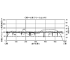
- FIG. 7 is a diagram showing an example of a reception level 60 when the deterioration diagnosis device 30 according to the first embodiment detects a sign of deterioration of ground equipment.
- the determination unit 31 of the deterioration diagnosis device 30 detects a sign of deterioration of the ground equipment in the specific block section. judge.
- FIG. 8 is a diagram showing an example of a reception level 60 when the deterioration diagnosis device 30 according to the first embodiment detects a sign of deterioration of the on-board equipment of the train 15. As shown in FIG.
- the determination unit 31 of the deterioration diagnosis device 30 is a sign of deterioration of the on-board equipment of the train 15 when a plurality of block sections, that is, the reception level 60 as a whole is equal to or less than the determination threshold value 62. Is determined to have been detected.
- the deterioration diagnosis device 30 may be mounted on the train 15. In this case, the deterioration diagnosis system 100 may delete the data management device 20 so that the vehicle information management device 12 of the on-board device 10 and the deterioration diagnosis device 30 directly communicate with each other. Even when mounted on the train 15, the deterioration diagnosis device 30 can detect a sign of deterioration of the on-board equipment of the train 15 with the same accuracy as when it is installed on the ground. Further, even when mounted on the train 15, the accuracy of the deterioration diagnosis device 30 is lower than that when it is installed on the ground, but by performing the determination a plurality of times, a sign of deterioration of the ground equipment is detected. can do.
- the storage unit 32 is a memory.
- the determination unit 31 is realized by a processing circuit.
- the processing circuit may be a processor and memory for executing a program stored in the memory, or may be dedicated hardware.
- FIG. 9 is a diagram showing an example in which the processing circuit included in the deterioration diagnosis device 30 according to the first embodiment is configured by a processor and a memory.
- the processing circuit is composed of the processor 91 and the memory 92, each function of the processing circuit of the deterioration diagnosis device 30 is realized by software, firmware, or a combination of software and firmware.
- the software or firmware is written as a program and stored in the memory 92.
- each function is realized by the processor 91 reading and executing the program stored in the memory 92. That is, the processing circuit includes a memory 92 for storing a program in which the processing of the deterioration diagnosis device 30 is eventually executed. It can also be said that these programs cause the computer to execute the procedure and method of the deterioration diagnosis device 30.
- the processor 91 may be a CPU (Central Processing Unit), a processing device, an arithmetic unit, a microprocessor, a microcomputer, a DSP (Digital Signal Processor), or the like.
- the memory 92 includes, for example, non-volatile or volatile such as RAM (Random Access Memory), ROM (Read Only Memory), flash memory, EPROM (Erasable Programmable ROM), EEPROM (registered trademark) (Electrically EPROM).
- RAM Random Access Memory
- ROM Read Only Memory
- flash memory EPROM (Erasable Programmable ROM), EEPROM (registered trademark) (Electrically EPROM).
- Semiconductor memory magnetic disk, flexible disk, optical disk, compact disk, mini disk, DVD (Digital Versatile Disc), etc. are applicable.
- FIG. 10 is a diagram showing an example in which the processing circuit included in the deterioration diagnosis device 30 according to the first embodiment is configured by dedicated hardware.
- the processing circuit is composed of dedicated hardware
- the processing circuit 93 shown in FIG. 10 includes, for example, a single circuit, a composite circuit, a programmed processor, a parallel programmed processor, an ASIC (Application Specific Integrated Circuit), and the like. FPGA (Field Programmable Gate Array) or a combination of these is applicable.
- Each function of the deterioration diagnosis device 30 may be realized by the processing circuit 93 for each function, or each function may be collectively realized by the processing circuit 93.
- a part may be realized by dedicated hardware and a part may be realized by software or firmware.
- the processing circuit can realize each of the above-mentioned functions by the dedicated hardware, software, firmware, or a combination thereof.
- the measuring unit 11 is an interface capable of receiving a signal.
- the vehicle information management device 12 is realized by a processing circuit.
- the processing circuit may be a processor and memory for executing a program stored in the memory, or may be dedicated hardware.
- the deterioration diagnosis device 30 is measured when a signal is received from the on-board device 10 by the train 15 via the data management device 20.
- the information of the reception level 60 is acquired, and the reception level 60 and the determination threshold value 62 are used to detect a sign of deterioration of the ground equipment or the on-board equipment of the train 15.
- the reception level 60 becomes the determination threshold value 62 or less in a plurality of block sections
- the deterioration diagnosis device 30 determines that it has detected a sign of deterioration of the on-board equipment, and determines that the reception level is detected in a specific block section.
- the deterioration diagnosis device 30 can detect a sign that the train 15 cannot receive the signal used for the operation of the train 15. As a result, the user can recognize that either the ground equipment or the on-board equipment of the train 15 shows a sign of deterioration, and can take measures such as inspection, repair, and replacement of the equipment. As a result, in the system for operating the train 15, the ground equipment or the on-board equipment of the train 15 deteriorates during the operation of the train 15, the train 15 cannot receive the signal, and the operation of the train 15 is stopped. Can be avoided.
- Embodiment 2 the determination unit 31 of the deterioration diagnosis device 30 considers a no-signal state at the boundary of the block section when the period during which the reception level 60 becomes the minimum operation level threshold value 61 or less is the first period or less. Therefore, it was considered that the minimum operation level threshold value was not equal to or less than 61.
- the determination unit 31 of the deterioration diagnosis device 30 outputs an alarm when the period during which the reception level 60 becomes the minimum operation level threshold value 61 or less is the third period or more, which is shorter than the first period.
- FIG. 11 is a diagram showing an image of the determination process in the determination unit 31 of the deterioration diagnosis device 30 according to the second embodiment.
- the horizontal axis represents time and the vertical axis represents reception level 60.
- the determination unit 31 of the deterioration diagnosis device 30 indicates that the period during which the reception level 60 is equal to or less than the minimum operation level threshold value 61 is shorter than the first period 63, but is longer than the defined third period 64. If it is too long, an alarm is output.
- the third period 64 is, for example, a period in which a margin is provided for a period in which the reception level 60 drops at the boundary of the block section when both the ground equipment and the on-board equipment of the train 15 are in the state at the start of business. do.
- the determination unit 31 detects a sign of deterioration of either the ground equipment or the on-board equipment of the train 15. It presumes that there is a possibility of this and outputs an alarm. Further, the determination unit 31 may detect a sign of deterioration of the ground equipment when the period during which the reception level 60 becomes the minimum operation level threshold value 61 or less is longer than the third period 64 for the plurality of trains 15. It is possible to presume that there is an alarm and output an alarm.
- the determination unit 31 compares the reception level 60 with the minimum operation level threshold value 61, and the period during which the reception level 60 becomes the minimum operation level threshold value 61 or less is a defined period of 64 or more. In this case, an alarm indicating that the period in which the reception level 60 becomes the minimum operation level threshold value 61 or less is the third period 64 or more, which is the specified period, is output. As a result, the user who has confirmed the alarm can recognize that either the ground equipment or the on-board equipment of the train 15 may show a sign of deterioration, and can perform maintenance or the like.
- the determination unit 31 indicates that the ground equipment is a sign of deterioration when the reception level 60 becomes the minimum operation level threshold value 61 or less for the plurality of trains 15 and becomes the third period 64 or more, which is the defined period.
- An alarm may be output indicating that there is a possibility.
- the deterioration diagnosis device 30 compares the reception level 60 with the minimum operation level threshold value 61, and the reception level 60 is equal to or less than the minimum operation level threshold value 61. An alarm is output when the third period 64 or more, which is the specified period, is reached. As a result, the deterioration diagnosis device 30 can show the user in advance the ground equipment that may detect a sign of deterioration or the on-board equipment of the train 15.
- the determination unit 31 of the deterioration diagnosis device 30 outputs an alarm when the period during which the reception level 60 becomes the determination threshold value 62 or less is shorter than the second period but longer than the specified fourth period. May be good. Specifically, in the operation of the flowchart shown in FIG. 5, in the case of step S22: No, the determination unit 31 further determines whether or not the reception level 60 is equal to or less than the determination threshold value 62 and continues for the specified fourth period. To confirm. When the reception level 60 is equal to or less than the determination threshold value 62 and continues for the specified fourth period, the determination unit 31 performs the same operation as the operations from step S23 to step S25. As a result, the determination unit 31 can indicate to the user in advance the ground equipment that may detect a sign of deterioration or the on-board equipment of the train 15.
- Embodiment 3 In the first embodiment, the determination unit 31 of the deterioration diagnosis device 30 compares the reception level 60 with one determination threshold value 62. In the third embodiment, the determination unit 31 of the deterioration diagnosis device 30 compares the reception level 60 with the plurality of determination threshold values.
- FIG. 12 is a diagram showing an image of the determination process in the determination unit 31 of the deterioration diagnosis device 30 according to the third embodiment.
- FIG. 12 shows the image of the determination process of the first embodiment, in which the determination threshold value 62 is set to the first determination threshold value 65 and the second determination threshold value 66 is added to FIGS. 6 to 8.
- the determination unit 31 of the deterioration diagnosis device 30 deteriorates the ground equipment in a specific block section when the reception level 60 is larger than the first determination threshold value 65 but the reception level 60 is equal to or less than the second determination threshold value 66. Outputs an alarm indicating that there is a tendency.
- the user who has confirmed the alarm can perform maintenance and the like on the ground equipment in a specific block section more intensively than the ground equipment in another block section.
- the storage unit 32 stores a plurality of determination threshold values as determination threshold values.
- the determination unit 31 compares the reception level 60 with the plurality of determination thresholds, and outputs an alarm based on each determination threshold.
- the determination unit 31 of the deterioration diagnosis device 30 outputs an alarm as the on-board equipment of the train 15 tends to deteriorate when the reception level 60 becomes the second determination threshold value 66 or less in a plurality of block sections. be able to.
- the deterioration diagnosis device 30 compares the reception level 60 with a plurality of judgment threshold values and outputs an alarm based on each judgment threshold value. bottom. As a result, the deterioration diagnosis device 30 can output an alarm according to the current state of the reception level 60 to the user.
- the configuration shown in the above embodiments is an example, and can be combined with another known technique, can be combined with each other, and does not deviate from the gist. It is also possible to omit or change a part of the configuration.
Abstract
A deterioration diagnostic device (30) comprises: a determination unit (31) for acquiring a reception level measured when a signal from a structure installed on the ground has been received by a train (15) in which the received signal is used to control an operation of the train (15), and for detecting a sign of deterioration of on-ground equipment or on-vehicle equipment of the train (15) using the reception level and a determination threshold value; and a storage unit (32) for storing the determination threshold value.
Description
本開示は、列車の運行に使用される設備の劣化を診断する劣化診断装置、車上装置、劣化診断システムおよび劣化診断方法に関する。
This disclosure relates to a deterioration diagnosis device, an on-board device, a deterioration diagnosis system, and a deterioration diagnosis method for diagnosing deterioration of equipment used for train operation.
従来、ATC(Automatic Train Control)車上装置を搭載した列車は、レールに流れるATC信号を受信し、ATC信号で示される速度であって、先行列車との間隔などに応じた速度に従って走行する制御を行っている。このような技術が特許文献1において開示されている。
Conventionally, a train equipped with an ATC (Automatic Train Control) on-board device receives an ATC signal flowing on a rail and controls the train to travel according to the speed indicated by the ATC signal, such as the distance from the preceding train. It is carried out. Such a technique is disclosed in Patent Document 1.
しかしながら、上記従来の技術によれば、ATC車上装置を搭載した列車は、列車に搭載されるATC信号の受電器、ATC信号を送信する地上側の地上装置などの設備の劣化によって異常が発生した場合、ATC信号を受信できなくなる。ATC信号を受信できなくなった列車は、先行列車との間隔などに応じた速度の制御ができないため、運行を停止してしまう、という問題があった。
However, according to the above-mentioned conventional technique, a train equipped with an ATC on-board device causes an abnormality due to deterioration of equipment such as an ATC signal receiver mounted on the train and a ground device on the ground side for transmitting the ATC signal. If this is the case, the ATC signal cannot be received. There is a problem that the train that cannot receive the ATC signal stops operating because the speed cannot be controlled according to the distance from the preceding train.
本開示は、上記に鑑みてなされたものであって、列車の運行に使用される信号を列車が受信できなくなる予兆を検知可能な劣化診断装置を得ることを目的とする。
The present disclosure has been made in view of the above, and an object of the present disclosure is to obtain a deterioration diagnosis device capable of detecting a sign that a train cannot receive a signal used for train operation.
上述した課題を解決し、目的を達成するために、本開示の劣化診断装置は、地上に設置された構造物から受信した信号を用いて列車の運行の制御に使用する列車において信号を受信したときに測定された受信レベルを取得し、受信レベルと判定閾値とを用いて地上設備または列車の車上設備の劣化の予兆を検知する判定部と、判定閾値を記憶する記憶部と、を備えることを特徴とする。
In order to solve the above-mentioned problems and achieve the object, the deterioration diagnostic apparatus of the present disclosure receives a signal in a train used for controlling train operation by using a signal received from a structure installed on the ground. It is provided with a determination unit that acquires a reception level measured at times and detects a sign of deterioration of ground equipment or on-board equipment of a train using the reception level and a determination threshold value, and a storage unit that stores the determination threshold value. It is characterized by that.
本開示によれば、劣化診断装置は、列車の運行に使用される信号を列車が受信できなくなる予兆を検知できる、という効果を奏する。
According to the present disclosure, the deterioration diagnosis device has an effect of being able to detect a sign that the train cannot receive the signal used for the operation of the train.
以下に、本開示の実施の形態に係る劣化診断装置、車上装置、劣化診断システムおよび劣化診断方法を図面に基づいて詳細に説明する。
Hereinafter, the deterioration diagnosis device, the on-board device, the deterioration diagnosis system, and the deterioration diagnosis method according to the embodiment of the present disclosure will be described in detail based on the drawings.
実施の形態1.
図1は、実施の形態1に係る劣化診断システム100の構成例を示す図である。劣化診断システム100は、車上装置10と、データ管理装置20と、劣化診断装置30と、を備える。列車15は、地上に設置された地上子40、レール50などから受信した信号を用いて、列車15の運行の制御に使用する。列車15は、複数の車両から構成されていてもよいし、図1に示すように1つの車両からなる単行であってもよい。列車15は、車上装置10と、車上子13と、受電器14と、を備える。車上子13は、地上に設置された地上子40から、地上子40の位置情報などの情報を含む信号を受信する。車上子13は、地上子40との間で信号を送受信してもよい。受電器14は、地上に設置されたレール50から、列車15に対する制限速度を示す速度情報などの情報を含む信号を受信する。列車15は、車上装置10がATC車上装置の機能を有していてもよいし、車上装置10とは別に図示しないATC車上装置を備えていてもよい。 Embodiment 1.
FIG. 1 is a diagram showing a configuration example of thedeterioration diagnosis system 100 according to the first embodiment. The deterioration diagnosis system 100 includes an on-board device 10, a data management device 20, and a deterioration diagnosis device 30. The train 15 is used to control the operation of the train 15 by using signals received from the ground element 40, the rail 50, and the like installed on the ground. The train 15 may be composed of a plurality of vehicles, or may be a single train composed of one vehicle as shown in FIG. The train 15 includes an on-board device 10, an on-board element 13, and a power receiver 14. The on-board child 13 receives a signal including information such as the position information of the ground element 40 from the ground element 40 installed on the ground. The on-board element 13 may send and receive signals to and from the ground element 40. The power receiver 14 receives a signal from the rail 50 installed on the ground, including information such as speed information indicating the speed limit for the train 15. The train 15 may have the on-board device 10 having the function of the ATC on-board device, or may have an ATC on-board device (not shown) separately from the on-board device 10.
図1は、実施の形態1に係る劣化診断システム100の構成例を示す図である。劣化診断システム100は、車上装置10と、データ管理装置20と、劣化診断装置30と、を備える。列車15は、地上に設置された地上子40、レール50などから受信した信号を用いて、列車15の運行の制御に使用する。列車15は、複数の車両から構成されていてもよいし、図1に示すように1つの車両からなる単行であってもよい。列車15は、車上装置10と、車上子13と、受電器14と、を備える。車上子13は、地上に設置された地上子40から、地上子40の位置情報などの情報を含む信号を受信する。車上子13は、地上子40との間で信号を送受信してもよい。受電器14は、地上に設置されたレール50から、列車15に対する制限速度を示す速度情報などの情報を含む信号を受信する。列車15は、車上装置10がATC車上装置の機能を有していてもよいし、車上装置10とは別に図示しないATC車上装置を備えていてもよい。 Embodiment 1.
FIG. 1 is a diagram showing a configuration example of the
車上装置10は、測定部11と、車両情報管理装置12と、を備える。測定部11は、列車15において、車上子13が地上子40から受信した信号、および受電器14がレール50から受信した信号から、列車15の運行の制御に必要な情報を抽出する。列車15の運行の制御に必要な情報とは、前述のように、地上子40の位置情報、列車15に対する制限速度を示す速度情報などである。また、測定部11は、列車15において、車上子13が地上子40からの信号を受信したときの受信レベルを測定し、受電器14がレール50からの信号を受信したときの受信レベルを測定する。受信レベルは、例えば、電界強度、SNR(Signal to Noise Ratio)などである。以降では、受信レベルが電界強度である場合を例にして説明する。
The on-board device 10 includes a measuring unit 11 and a vehicle information management device 12. In the train 15, the measuring unit 11 extracts information necessary for controlling the operation of the train 15 from the signal received by the on-board element 13 from the ground element 40 and the signal received by the power receiver 14 from the rail 50. As described above, the information necessary for controlling the operation of the train 15 includes the position information of the ground element 40, the speed information indicating the speed limit for the train 15, and the like. Further, the measuring unit 11 measures the reception level when the on-board element 13 receives the signal from the ground element 40 on the train 15, and determines the reception level when the power receiver 14 receives the signal from the rail 50. taking measurement. The reception level is, for example, electric field strength, SNR (Signal to Noise Ratio), or the like. Hereinafter, the case where the reception level is the electric field strength will be described as an example.
車両情報管理装置12は、列車15の位置を管理する。車両情報管理装置12は、例えば、車上子13が地上子40から受信した信号に含まれる情報である地上子40の位置情報で示される位置に、図示しない速度発電機などから得られる列車15の速度の情報および走行時間の情報から算出される走行距離を加算することで、列車15の位置を算出することができる。車両情報管理装置12は、GPS(Global Positioning System)などを用いて列車15の位置を管理してもよい。車両情報管理装置12は、例えば、TIMS(Train Integrated Management System)などの装置である。車両情報管理装置12は、測定部11で測定された受信レベルおよび列車15の位置の情報を、無線通信によって、データ管理装置20を介して劣化診断装置30に送信する。
The vehicle information management device 12 manages the position of the train 15. The vehicle information management device 12 is, for example, a train 15 obtained from a speed generator (not shown) or the like at a position indicated by the position information of the ground element 40, which is information included in the signal received from the ground element 40 by the on-board element 13. The position of the train 15 can be calculated by adding the mileage calculated from the speed information and the traveling time information. The vehicle information management device 12 may manage the position of the train 15 by using GPS (Global Positioning System) or the like. The vehicle information management device 12 is, for example, a device such as TIMS (Train Integrated Management System). The vehicle information management device 12 transmits the reception level measured by the measurement unit 11 and the position information of the train 15 to the deterioration diagnosis device 30 via the data management device 20 by wireless communication.
データ管理装置20は、列車15に搭載された車上装置10の車両情報管理装置12から送信された受信レベルおよび列車15の位置の情報を、無線通信によって受信する。データ管理装置20は、受信した受信レベルおよび列車15の位置の情報を、劣化診断装置30に出力する。
The data management device 20 receives the reception level and the position information of the train 15 transmitted from the vehicle information management device 12 of the on-board device 10 mounted on the train 15 by wireless communication. The data management device 20 outputs the received reception level and the position information of the train 15 to the deterioration diagnosis device 30.
劣化診断装置30は、判定部31と、記憶部32と、を備える。判定部31は、データ管理装置20を介して車上装置10から、列車15において信号を受信したときに測定された受信レベルを取得する。判定部31は、受信レベルと、地上設備または列車15の車上設備の劣化の予兆を検知するための判定閾値とを用いて、地上設備または列車15の車上設備の劣化の予兆を検知する。地上設備とは、地上子40、レール50、地上子40およびレール50から送信される信号を生成する図示しない通信装置などの地上装置である。列車15の車上設備とは、車上子13、受電器14などである。地上設備または列車15の車上設備が劣化した場合、地上設備または列車15の車上設備が異常になり、列車15が信号を受信できなくなる状態になる。本実施の形態において、判定部31は、地上設備または列車15の車上設備が劣化に至っていないが、劣化に至る前の状態を劣化の予兆として検知する。具体的には、判定部31は、受信レベルと判定閾値とを比較する。判定部31は、受信レベルが判定閾値以下になった場合、地上設備または列車15の車上設備の劣化の予兆を検知したと判定する。判定部31の詳細な動作については後述する。
The deterioration diagnosis device 30 includes a determination unit 31 and a storage unit 32. The determination unit 31 acquires the reception level measured when the signal is received by the train 15 from the on-board device 10 via the data management device 20. The determination unit 31 detects the sign of deterioration of the ground equipment or the on-board equipment of the train 15 by using the reception level and the determination threshold value for detecting the sign of deterioration of the ground equipment or the on-board equipment of the train 15. .. The ground equipment is a ground device such as a communication device (not shown) that generates signals transmitted from the ground element 40, the rail 50, the ground element 40, and the rail 50. The on-board equipment of the train 15 is an on-board child 13, a power receiver 14, and the like. When the ground equipment or the on-board equipment of the train 15 deteriorates, the ground equipment or the on-board equipment of the train 15 becomes abnormal, and the train 15 cannot receive the signal. In the present embodiment, the determination unit 31 detects that the ground equipment or the on-board equipment of the train 15 has not deteriorated, but the state before the deterioration has occurred as a sign of deterioration. Specifically, the determination unit 31 compares the reception level with the determination threshold. When the reception level becomes equal to or lower than the determination threshold value, the determination unit 31 determines that it has detected a sign of deterioration of the ground equipment or the on-board equipment of the train 15. The detailed operation of the determination unit 31 will be described later.
記憶部32は、判定閾値を記憶している。また、記憶部32は、地上子40またはレール50から信号が送信されているか否かを判定するための最小動作レベル閾値を記憶している。例えば、劣化診断システム100を使用するユーザは、判定閾値および最小動作レベル閾値を予め記憶部32に記憶させておくこととする。なお、判定閾値は、適宜変更するようにしてもよい。
The storage unit 32 stores the determination threshold value. Further, the storage unit 32 stores the minimum operation level threshold value for determining whether or not a signal is transmitted from the ground element 40 or the rail 50. For example, the user who uses the deterioration diagnosis system 100 stores the determination threshold value and the minimum operation level threshold value in the storage unit 32 in advance. The determination threshold value may be changed as appropriate.
地上子40は、地上子40が設置された位置を示す位置情報を含む信号を送信する。地上子40は、位置情報に代えて、地上子40を特定可能な識別情報を含む信号を送信してもよい。レール50は、列車15の走行方向の前方を走行する先行列車との間隔などに応じた、列車15に対する制限速度を示す速度情報を含む信号を送信する。地上子40およびレール50は、地上に設置された構造物である。
The ground element 40 transmits a signal including position information indicating the position where the ground element 40 is installed. The ground element 40 may transmit a signal including identification information that can identify the ground element 40 instead of the position information. The rail 50 transmits a signal including speed information indicating a speed limit for the train 15 according to the distance from the preceding train traveling in front of the train 15 in the traveling direction. The ground element 40 and the rail 50 are structures installed on the ground.
つづいて、劣化診断システム100において、劣化診断装置30が、地上設備または列車15の車上設備の劣化の予兆を検知する動作について説明する。ここでは、一例として、列車15がレール50から信号を受信する場合について説明する。なお、列車15が地上子40から信号を受信する場合も同様の動作となる。
Next, in the deterioration diagnosis system 100, the operation in which the deterioration diagnosis device 30 detects a sign of deterioration of the ground equipment or the on-board equipment of the train 15 will be described. Here, as an example, a case where the train 15 receives a signal from the rail 50 will be described. The same operation is performed when the train 15 receives a signal from the ground element 40.
一般的に、列車15を運行するシステムは、列車15が走行する区間を複数の閉塞区間に分割している。各閉塞区間のレール50は、列車15の走行方向の前方を走行する先行列車との間隔などに応じた速度であって、列車15に対する制限速度を示す速度情報を含む信号を送信する。レール50は、閉塞区間の単位で、各閉塞区間での速度情報を含む信号を送信することになる。レール50から送信される信号は、列車15が走行するレール50から閉塞区間毎に出力される。すなわち、列車15を運行するシステムは、地上設備として、閉塞区間毎に異なる信号を送信可能な設備を備えている。そのため、劣化診断装置30は、図2および図3に示すように、全ての閉塞区間において受信レベルが低下したのか、または特定の閉塞区間において受信レベルが低下したのかによって、地上設備または列車15の車上設備の劣化の予兆を検知することができる。
In general, the system for operating the train 15 divides the section in which the train 15 travels into a plurality of block sections. The rail 50 in each block section transmits a signal including speed information indicating a speed limit with respect to the train 15, which is a speed corresponding to a distance from a preceding train traveling in front of the train 15 in the traveling direction. The rail 50 transmits a signal including speed information in each block section in units of block sections. The signal transmitted from the rail 50 is output from the rail 50 on which the train 15 travels for each block section. That is, the system for operating the train 15 is provided with equipment capable of transmitting different signals for each block section as ground equipment. Therefore, as shown in FIGS. 2 and 3, the deterioration diagnosis device 30 of the ground equipment or the train 15 depends on whether the reception level is lowered in all the block sections or the reception level is lowered in a specific block section. It is possible to detect signs of deterioration of on-board equipment.
図2は、実施の形態1に係る劣化診断システム100において列車15の車上設備が劣化の予兆を示す状態になった場合の受信レベルの変化の推移を示す図である。図2(a)から図2(c)において、横軸は列車15の走行位置を示し、縦軸は列車15での信号の受信レベルを示す。複数の列車15が運行されている場合において、特定のZ編成の列車15に着目する。図2(a)に示すように、Z編成の列車15は、営業開始時において良好な受信レベルである。一般的に、機器類は、経年変化によって性能が低下する。Z編成の列車15においても、受電器14などの受信性能が経年変化によって劣化することが予想される。図2(b)に示すように、Z編成の列車15は、営業開始からT1年後、全ての閉塞区間において営業開始時よりも受信レベルが低下する。図2(c)に示すように、Z編成の列車15は、営業開始からT2年後、全ての閉塞区間においてさらに受信レベルが低下する。なお、T2>T1とする。
FIG. 2 is a diagram showing a transition of a change in the reception level when the on-board equipment of the train 15 is in a state showing a sign of deterioration in the deterioration diagnosis system 100 according to the first embodiment. In FIGS. 2A to 2C, the horizontal axis indicates the running position of the train 15, and the vertical axis indicates the signal reception level of the train 15. When a plurality of trains 15 are in operation, attention is paid to the specific Z train 15. As shown in FIG. 2A, the Z train 15 has a good reception level at the start of business. In general, the performance of equipment deteriorates due to aging. Even in the Z train 15, it is expected that the reception performance of the power receiver 14 and the like will deteriorate due to aging. As shown in FIG. 2B, the reception level of the Z train 15 is lower than that at the start of business in all the block sections T1 year after the start of business. As shown in FIG. 2C, the reception level of the Z train 15 is further lowered in all the block sections T2 years after the start of business. It should be noted that T2> T1.
このように、劣化診断装置30は、複数の閉塞区間において受信レベルが低下している場合、Z編成の列車15が備える車上設備、例えば受電器14が劣化の予兆を示していると判定することができる。具体的には、劣化診断装置30の判定部31は、複数の閉塞区間において受信レベルが低下し、受信レベルが判定閾値以下になった場合、Z編成の列車15が備える車上設備の劣化の予兆を検知したと判定する。
As described above, when the reception level is lowered in the plurality of block sections, the deterioration diagnosis device 30 determines that the on-board equipment provided in the Z train 15 such as the power receiver 14 shows a sign of deterioration. be able to. Specifically, the determination unit 31 of the deterioration diagnosis device 30 deteriorates the on-board equipment of the Z train 15 when the reception level drops below the determination threshold value in a plurality of block sections. It is determined that a sign has been detected.
図3は、実施の形態1に係る劣化診断システム100において地上設備が劣化の予兆を示す状態になった場合の受信レベルの変化の推移を示す図である。図3(a)から図3(c)において、横軸は列車15の走行位置を示し、縦軸は列車15での信号の受信レベルを示す。複数の列車15が運行されている場合において、A編成の列車15からZ編成の列車15の複数の列車15に着目する。図3(a)に示すように、A~Z編成の列車15は、営業開始時において良好な受信レベルである。一般的に、機器類は、経年変化によって性能が低下する。地上設備においても、レール50から信号を送信する図示しない通信装置の送信性能が経年変化によって劣化することが予想される。図3(b)に示すように、A~Z編成の列車15は、営業開始からT1年後、特定の閉塞区間において営業開始時よりも受信レベルが低下する。図3(c)に示すように、A~Z編成の列車15は、営業開始からT2年後、特定の閉塞区間においてさらに受信レベルが低下する。なお、T2>T1とする。
FIG. 3 is a diagram showing a transition of a change in the reception level when the ground equipment in the deterioration diagnosis system 100 according to the first embodiment is in a state showing a sign of deterioration. In FIGS. 3 (a) to 3 (c), the horizontal axis represents the running position of the train 15, and the vertical axis represents the signal reception level of the train 15. When a plurality of trains 15 are in operation, attention is paid to the plurality of trains 15 of the A train 15 to the Z train 15. As shown in FIG. 3A, the trains 15 of the A to Z trains have a good reception level at the start of business. In general, the performance of equipment deteriorates due to aging. Even in ground equipment, it is expected that the transmission performance of a communication device (not shown) that transmits a signal from the rail 50 will deteriorate due to aging. As shown in FIG. 3B, the reception level of the trains 15 of the A to Z trains is lower than that at the start of business in a specific block section T1 year after the start of business. As shown in FIG. 3C, the reception level of the trains 15 of the A to Z trains further decreases in a specific block section two years after the start of business. It should be noted that T2> T1.
このように、劣化診断装置30は、A~Z編成の列車15において特定の閉塞区間で受信レベルが低下している場合、A~Z編成の全ての列車15が備える車上設備の劣化の予兆を検知し、かつ特定の閉塞区間だけ受信レベルが低下する可能性は低いと判定する。劣化診断装置30は、A~Z編成に向けてレール50から信号を送信する特定の閉塞区間の地上設備、例えば通信装置が劣化の予兆を示していると判定することができる。具体的には、劣化診断装置30の判定部31は、特定の閉塞区間において受信レベルが低下し、受信レベルが判定閾値以下になった場合、特定の閉塞区間の地上設備の劣化の予兆を検知したと判定する。
As described above, when the reception level of the A to Z trains 15 is lowered in a specific block section, the deterioration diagnosis device 30 is a sign of deterioration of the on-board equipment of all the A to Z trains 15. Is detected, and it is judged that the possibility that the reception level drops only in a specific block section is low. The deterioration diagnosis device 30 can determine that the ground equipment in a specific block section, for example, a communication device, which transmits a signal from the rail 50 toward the A to Z formation, is showing a sign of deterioration. Specifically, the determination unit 31 of the deterioration diagnosis device 30 detects a sign of deterioration of the ground equipment in the specific block section when the reception level drops below the determination threshold in the specific block section. It is determined that it has been done.
なお、図2および図3では、受信レベルが所々で低下しているが、これは、閉塞区間の境界を示している。レール50には、閉塞区間の境界において、信号が流れない領域が存在する。すなわち、閉塞区間の境界は、無信号状態になる。このように、閉塞区間の境界では、車上設備および地上設備が劣化の予兆を示していなくても、列車15において、信号の受信レベルが低下する。そのため、劣化診断装置30は、列車15が閉塞区間の境界を走行中に列車15で測定された受信レベルについては、車上設備または地上設備の劣化の予兆の判定に使用しないようにする。
Note that in FIGS. 2 and 3, the reception level is lowered in some places, which indicates the boundary of the block section. The rail 50 has a region where no signal flows at the boundary of the block section. That is, the boundary of the block section becomes a no-signal state. As described above, at the boundary of the block section, the signal reception level is lowered in the train 15 even if the on-board equipment and the ground equipment do not show signs of deterioration. Therefore, the deterioration diagnosis device 30 does not use the reception level measured by the train 15 while the train 15 is traveling on the boundary of the block section for determining the sign of deterioration of the on-board equipment or the ground equipment.
まず、劣化診断システム100が備える車上装置10の動作について説明する。図4は、実施の形態1に係る車上装置10の動作を示すフローチャートである。車上装置10において、測定部11は、レール50から送信された信号を受電器14で受信したときの受信レベルを測定する(ステップS11)。測定部11は、測定した受信レベルの情報を車両情報管理装置12に出力する。車両情報管理装置12は、測定部11で測定された受信レベルおよび列車15の位置の情報を、データ管理装置20を介して劣化診断装置30に送信する(ステップS12)。
First, the operation of the on-board device 10 included in the deterioration diagnosis system 100 will be described. FIG. 4 is a flowchart showing the operation of the on-board device 10 according to the first embodiment. In the on-board device 10, the measuring unit 11 measures the reception level when the signal transmitted from the rail 50 is received by the power receiver 14 (step S11). The measuring unit 11 outputs the measured reception level information to the vehicle information management device 12. The vehicle information management device 12 transmits the reception level measured by the measurement unit 11 and the position information of the train 15 to the deterioration diagnosis device 30 via the data management device 20 (step S12).
車上装置10は、受信レベル60と最小動作レベル閾値61とを比較する。受信レベル60が最小動作レベル閾値61以下、かつ規定された第1の期間継続した場合(ステップS13:Yes)、車上装置10は、非常ブレーキの動作を指示する(ステップS14)。第1の期間は、列車15の車上設備および地上設備が劣化の予兆を示していない良好な状態において、閉塞区間の境界で受信レベル60が瞬間的に低下する期間よりも長い期間とする。受信レベル60が最小動作レベル閾値61より大きい場合、または受信レベル60が最小動作レベル閾値61以下になったが規定された第1の期間継続しなかった場合(ステップS13:No)、車上装置10は、動作を終了する。なお、上記では、車上装置10がATC車上装置の機能を有する場合を例に説明しているが、車上装置10とは別に列車15が図示しないATC車上装置を備える場合には、ATC車上装置がステップS13およびステップS14の動作を行うようにしてもよい。車上装置10は、図4に示す動作を定期的に繰り返し実施する。
The on-board device 10 compares the reception level 60 with the minimum operation level threshold value 61. When the reception level 60 is equal to or less than the minimum operation level threshold value 61 and continues for the specified first period (step S13: Yes), the on-board device 10 instructs the operation of the emergency brake (step S14). The first period is a period longer than the period in which the reception level 60 momentarily drops at the boundary of the block section in a good condition in which the on-board equipment and the ground equipment of the train 15 show no sign of deterioration. When the reception level 60 is larger than the minimum operation level threshold value 61, or when the reception level 60 is equal to or less than the minimum operation level threshold value 61 but does not continue for the specified first period (step S13: No), the on-board device. 10 ends the operation. In the above description, the case where the on-board device 10 has the function of the ATC on-board device is described as an example, but when the train 15 is provided with the ATC on-board device (not shown) in addition to the on-board device 10. The ATC on-board device may perform the operations of steps S13 and S14. The on-board device 10 periodically repeats the operation shown in FIG.
つぎに、劣化診断システム100が備える劣化診断装置30の動作について説明する。図5は、実施の形態1に係る劣化診断装置30の動作を示すフローチャートである。劣化診断装置30において、判定部31は、データ管理装置20を介して車上装置10から、受信レベルおよび列車15の位置の情報を取得する(ステップS21)。判定部31は、以降で説明するように、受信レベルと、最小動作レベル閾値および判定閾値との比較を行う。図6は、実施の形態1に係る劣化診断装置30の判定部31における判定処理のイメージを示す図である。図6において、横軸は○駅から△駅への列車15の走行位置を示している。また、図6において、左側の縦軸は受信レベル60の大きさを示し、右側の縦軸は列車15の速度Vを示している。図6において、左側の縦軸は、最小動作レベル閾値61、および判定閾値62の大きさも示している。なお、図6では、受信レベル60の大きさを、レール50に流れる電流に換算した値で表しているが、図2および図3と同様、電圧値で表してもよい。
Next, the operation of the deterioration diagnosis device 30 included in the deterioration diagnosis system 100 will be described. FIG. 5 is a flowchart showing the operation of the deterioration diagnosis device 30 according to the first embodiment. In the deterioration diagnosis device 30, the determination unit 31 acquires the reception level and the position information of the train 15 from the on-board device 10 via the data management device 20 (step S21). The determination unit 31 compares the reception level with the minimum operation level threshold value and the determination threshold value, as will be described later. FIG. 6 is a diagram showing an image of the determination process in the determination unit 31 of the deterioration diagnosis device 30 according to the first embodiment. In FIG. 6, the horizontal axis shows the running position of the train 15 from the ○ station to the △ station. Further, in FIG. 6, the vertical axis on the left side indicates the magnitude of the reception level 60, and the vertical axis on the right side indicates the speed V of the train 15. In FIG. 6, the vertical axis on the left side also shows the magnitudes of the minimum operation level threshold value 61 and the determination threshold value 62. Although the magnitude of the reception level 60 is represented by a value converted into a current flowing through the rail 50 in FIG. 6, it may be represented by a voltage value as in FIGS. 2 and 3.
前述のようにレール50は閉塞区間の境界で信号が流れないため、判定部31は、閉塞区間の境界で判定を行わないようにする。ここで、判定部31は、受信レベル60と、最小動作レベル閾値61および判定閾値62との比較について、連続して行ってもよいし、閉塞区間の境界を外して、すなわち規定されたタイミングから規定された期間において行ってもよい。判定部31は、受信レベル60と最小動作レベル閾値61および判定閾値62との比較を連続して行う場合、閉塞区間の境界で瞬間的に低下した受信レベル60については判定の対象にしないようにする。判定部31は、受信レベル60と最小動作レベル閾値61および判定閾値62との比較を規定されたタイミングから規定された期間において行う場合、例えば、列車15が各閉塞区間の中心を走行するタイミングから規定された期間に走行する際に測定された受信レベル60を判定の対象とする。規定された期間は、列車15の速度Vに応じて変動してもよい。
As described above, since the signal does not flow on the rail 50 at the boundary of the block section, the determination unit 31 does not make a judgment at the boundary of the block section. Here, the determination unit 31 may continuously compare the reception level 60 with the minimum operation level threshold value 61 and the determination threshold value 62, or remove the boundary of the block section, that is, from the specified timing. It may be done in the specified period. When the determination unit 31 continuously compares the reception level 60 with the minimum operation level threshold value 61 and the determination threshold value 62, the determination unit 31 does not determine the reception level 60 that momentarily drops at the boundary of the block section. do. When the determination unit 31 compares the reception level 60 with the minimum operation level threshold value 61 and the determination threshold value 62 from a specified timing to a specified period, for example, from the timing when the train 15 travels in the center of each block section. The reception level 60 measured when traveling in the specified period is subject to the determination. The specified period may vary depending on the speed V of the train 15.
判定部31は、受信レベル60の変動の時間的推移について、データ管理装置20を介して車上装置10から受信レベル60の情報を取得するタイミングで認識することが可能である。また、判定部31は、データ管理装置20を介して車上装置10から列車15の速度Vの情報も取得し、図6に示す列車15のある走行位置の範囲を速度Vで除算することで、当該走行位置までの距離を列車15が走行するために要した期間を算出することができる。判定部31は、図6に示すある範囲の走行位置までの距離を列車15が走行するために要した期間を算出することで、当該走行位置までの距離の範囲における受信レベル60の変動の時間的推移を認識することが可能である。
The determination unit 31 can recognize the temporal transition of the fluctuation of the reception level 60 at the timing of acquiring the information of the reception level 60 from the on-board device 10 via the data management device 20. Further, the determination unit 31 also acquires information on the speed V of the train 15 from the on-board device 10 via the data management device 20, and divides the range of the traveling position of the train 15 shown in FIG. 6 by the speed V. , The period required for the train 15 to travel the distance to the traveling position can be calculated. The determination unit 31 calculates the period required for the train 15 to travel the distance to the traveling position in a certain range shown in FIG. 6, and thus the time of fluctuation of the reception level 60 in the range of the distance to the traveling position. It is possible to recognize the transition.
図5の説明に戻る。判定部31は、記憶部32から判定閾値62を読み出し、受信レベル60と判定閾値62とを比較する。受信レベル60が判定閾値62以下、かつ規定された第2の期間継続した場合(ステップS22:Yes)、判定部31は、特定の閉塞区間で受信レベル60が判定閾値62以下になっているのか、または複数の閉塞区間で受信レベル60が判定閾値62以下になっているのか判定する。第2の期間は、列車15の車上設備および地上設備が劣化の予兆を示していない良好な状態において、閉塞区間の境界で受信レベル60が瞬間的に低下する期間よりも長い期間とする。第2の期間は、列車15の速度Vに応じて変動してもよい。
Return to the explanation in Fig. 5. The determination unit 31 reads the determination threshold value 62 from the storage unit 32 and compares the reception level 60 with the determination threshold value 62. When the reception level 60 is the determination threshold value 62 or less and continues for the specified second period (step S22: Yes), the determination unit 31 asks whether the reception level 60 is the determination threshold value 62 or less in the specific block section. , Or, it is determined whether the reception level 60 is equal to or less than the determination threshold value 62 in the plurality of block sections. The second period is longer than the period in which the reception level 60 momentarily drops at the boundary of the block section in a good condition where the on-board equipment and the ground equipment of the train 15 show no sign of deterioration. The second period may vary depending on the speed V of the train 15.
特定の閉塞区間で受信レベル60が判定閾値62以下になっている場合(ステップS23:Yes)、判定部31は、列車15を運行するシステムにおいて、地上設備の劣化の予兆を検知したことを示すアラームを出力する(ステップS24)。判定部31は、アラームとして、例えば、劣化診断装置30が備える図示しない表示部に地上設備の劣化の予兆を検知したことを表示する。判定部31は、アラームとして、劣化診断装置30が備える図示しないLED(Light Emitting Diode)、スピーカーなどを用いて地上設備の劣化の予兆を検知したことをユーザに認識させてもよい。以降の説明で判定部31がアラームを出力する場合も同様とする。複数の閉塞区間で受信レベル60が判定閾値62以下になっている場合(ステップS23:No)、判定部31は、列車15を運行するシステムにおいて、列車15の車上設備の劣化の予兆を検知したことを示すアラームを出力する(ステップS25)。これにより、アラームを確認したユーザは、地上設備、または列車15の車上設備のいずれかが劣化の予兆を示していることを認識し、設備の点検、修理、交換などの処置を行うことができる。
When the reception level 60 is equal to or lower than the determination threshold value 62 in the specific block section (step S23: Yes), the determination unit 31 indicates that the system operating the train 15 has detected a sign of deterioration of the ground equipment. Output an alarm (step S24). As an alarm, the determination unit 31 displays, for example, that a sign of deterioration of the ground equipment has been detected on a display unit (not shown) included in the deterioration diagnosis device 30. As an alarm, the determination unit 31 may make the user recognize that a sign of deterioration of the ground equipment has been detected by using an LED (Light Emitting Diode), a speaker, or the like (not shown) included in the deterioration diagnosis device 30. The same applies to the case where the determination unit 31 outputs an alarm in the following description. When the reception level 60 is equal to or lower than the determination threshold value 62 in a plurality of block sections (step S23: No), the determination unit 31 detects a sign of deterioration of the on-board equipment of the train 15 in the system for operating the train 15. An alarm indicating that the operation has been performed is output (step S25). As a result, the user who confirms the alarm recognizes that either the ground equipment or the on-board equipment of the train 15 shows a sign of deterioration, and can take measures such as inspection, repair, and replacement of the equipment. can.
受信レベル60が判定閾値62より大きい場合、または受信レベル60が判定閾値62以下になったが規定された第2の期間継続しなかった場合(ステップS22:No)、判定部31は、動作を終了する。判定部31は、図5に示す動作を、連続して、または規定されたタイミングから規定された期間において、繰り返し実施する。
When the reception level 60 is larger than the determination threshold value 62, or when the reception level 60 is equal to or less than the determination threshold value 62 but does not continue for the specified second period (step S22: No), the determination unit 31 operates. finish. The determination unit 31 repeatedly performs the operation shown in FIG. 5 continuously or from a specified timing to a specified period.
図7は、実施の形態1に係る劣化診断装置30が地上設備の劣化の予兆を検知した場合の受信レベル60の例を示す図である。劣化診断装置30の判定部31は、図7に示すように特定の閉塞区間で受信レベル60が判定閾値62以下になっている場合、特定の閉塞区間の地上設備の劣化の予兆を検知したと判定する。図8は、実施の形態1に係る劣化診断装置30が列車15の車上設備の劣化の予兆を検知した場合の受信レベル60の例を示す図である。劣化診断装置30の判定部31は、図8に示すように、複数の閉塞区間、すなわち全体的に受信レベル60が判定閾値62以下になっている場合、列車15の車上設備の劣化の予兆を検知したと判定する。
FIG. 7 is a diagram showing an example of a reception level 60 when the deterioration diagnosis device 30 according to the first embodiment detects a sign of deterioration of ground equipment. As shown in FIG. 7, when the reception level 60 is equal to or lower than the determination threshold value 62 in the specific block section, the determination unit 31 of the deterioration diagnosis device 30 detects a sign of deterioration of the ground equipment in the specific block section. judge. FIG. 8 is a diagram showing an example of a reception level 60 when the deterioration diagnosis device 30 according to the first embodiment detects a sign of deterioration of the on-board equipment of the train 15. As shown in FIG. 8, the determination unit 31 of the deterioration diagnosis device 30 is a sign of deterioration of the on-board equipment of the train 15 when a plurality of block sections, that is, the reception level 60 as a whole is equal to or less than the determination threshold value 62. Is determined to have been detected.
なお、本実施の形態では、劣化診断装置30が、列車15の外部の地上側に設置されている場合について説明したが、これに限定されない。劣化診断システム100において、劣化診断装置30は、列車15に搭載されていてもよい。この場合、劣化診断システム100は、データ管理装置20を削除し、車上装置10の車両情報管理装置12と劣化診断装置30とが直接通信を行うようにしてもよい。列車15に搭載された場合でも、劣化診断装置30は、地上に設置されていた場合と同様の精度で、列車15の車上設備の劣化の予兆を検知することができる。また、列車15に搭載された場合でも、劣化診断装置30は、地上に設置されていた場合と比較して精度が低下するが、複数回判定を行うことで、地上設備の劣化の予兆を検知することができる。
In the present embodiment, the case where the deterioration diagnosis device 30 is installed on the ground side outside the train 15 has been described, but the present invention is not limited to this. In the deterioration diagnosis system 100, the deterioration diagnosis device 30 may be mounted on the train 15. In this case, the deterioration diagnosis system 100 may delete the data management device 20 so that the vehicle information management device 12 of the on-board device 10 and the deterioration diagnosis device 30 directly communicate with each other. Even when mounted on the train 15, the deterioration diagnosis device 30 can detect a sign of deterioration of the on-board equipment of the train 15 with the same accuracy as when it is installed on the ground. Further, even when mounted on the train 15, the accuracy of the deterioration diagnosis device 30 is lower than that when it is installed on the ground, but by performing the determination a plurality of times, a sign of deterioration of the ground equipment is detected. can do.
つづいて、劣化診断装置30のハードウェア構成について説明する。劣化診断装置30において、記憶部32はメモリである。判定部31は処理回路により実現される。処理回路は、メモリに格納されるプログラムを実行するプロセッサおよびメモリであってもよいし、専用のハードウェアであってもよい。
Next, the hardware configuration of the deterioration diagnosis device 30 will be described. In the deterioration diagnosis device 30, the storage unit 32 is a memory. The determination unit 31 is realized by a processing circuit. The processing circuit may be a processor and memory for executing a program stored in the memory, or may be dedicated hardware.
図9は、実施の形態1に係る劣化診断装置30が備える処理回路をプロセッサおよびメモリで構成する場合の例を示す図である。処理回路がプロセッサ91およびメモリ92で構成される場合、劣化診断装置30の処理回路の各機能は、ソフトウェア、ファームウェア、またはソフトウェアとファームウェアとの組み合わせにより実現される。ソフトウェアまたはファームウェアはプログラムとして記述され、メモリ92に格納される。処理回路では、メモリ92に記憶されたプログラムをプロセッサ91が読み出して実行することにより、各機能を実現する。すなわち、処理回路は、劣化診断装置30の処理が結果的に実行されることになるプログラムを格納するためのメモリ92を備える。また、これらのプログラムは、劣化診断装置30の手順および方法をコンピュータに実行させるものであるともいえる。
FIG. 9 is a diagram showing an example in which the processing circuit included in the deterioration diagnosis device 30 according to the first embodiment is configured by a processor and a memory. When the processing circuit is composed of the processor 91 and the memory 92, each function of the processing circuit of the deterioration diagnosis device 30 is realized by software, firmware, or a combination of software and firmware. The software or firmware is written as a program and stored in the memory 92. In the processing circuit, each function is realized by the processor 91 reading and executing the program stored in the memory 92. That is, the processing circuit includes a memory 92 for storing a program in which the processing of the deterioration diagnosis device 30 is eventually executed. It can also be said that these programs cause the computer to execute the procedure and method of the deterioration diagnosis device 30.
ここで、プロセッサ91は、CPU(Central Processing Unit)、処理装置、演算装置、マイクロプロセッサ、マイクロコンピュータ、またはDSP(Digital Signal Processor)などであってもよい。また、メモリ92には、例えば、RAM(Random Access Memory)、ROM(Read Only Memory)、フラッシュメモリ、EPROM(Erasable Programmable ROM)、EEPROM(登録商標)(Electrically EPROM)などの、不揮発性または揮発性の半導体メモリ、磁気ディスク、フレキシブルディスク、光ディスク、コンパクトディスク、ミニディスク、またはDVD(Digital Versatile Disc)などが該当する。
Here, the processor 91 may be a CPU (Central Processing Unit), a processing device, an arithmetic unit, a microprocessor, a microcomputer, a DSP (Digital Signal Processor), or the like. Further, the memory 92 includes, for example, non-volatile or volatile such as RAM (Random Access Memory), ROM (Read Only Memory), flash memory, EPROM (Erasable Programmable ROM), EEPROM (registered trademark) (Electrically EPROM). Semiconductor memory, magnetic disk, flexible disk, optical disk, compact disk, mini disk, DVD (Digital Versatile Disc), etc. are applicable.
図10は、実施の形態1に係る劣化診断装置30が備える処理回路を専用のハードウェアで構成する場合の例を示す図である。処理回路が専用のハードウェアで構成される場合、図10に示す処理回路93は、例えば、単一回路、複合回路、プログラム化したプロセッサ、並列プログラム化したプロセッサ、ASIC(Application Specific Integrated Circuit)、FPGA(Field Programmable Gate Array)、またはこれらを組み合わせたものが該当する。劣化診断装置30の各機能を機能別に処理回路93で実現してもよいし、各機能をまとめて処理回路93で実現してもよい。
FIG. 10 is a diagram showing an example in which the processing circuit included in the deterioration diagnosis device 30 according to the first embodiment is configured by dedicated hardware. When the processing circuit is composed of dedicated hardware, the processing circuit 93 shown in FIG. 10 includes, for example, a single circuit, a composite circuit, a programmed processor, a parallel programmed processor, an ASIC (Application Specific Integrated Circuit), and the like. FPGA (Field Programmable Gate Array) or a combination of these is applicable. Each function of the deterioration diagnosis device 30 may be realized by the processing circuit 93 for each function, or each function may be collectively realized by the processing circuit 93.
なお、劣化診断装置30の各機能について、一部を専用のハードウェアで実現し、一部をソフトウェアまたはファームウェアで実現するようにしてもよい。このように、処理回路は、専用のハードウェア、ソフトウェア、ファームウェア、またはこれらの組み合わせによって、上述の各機能を実現することができる。
Note that, for each function of the deterioration diagnosis device 30, a part may be realized by dedicated hardware and a part may be realized by software or firmware. As described above, the processing circuit can realize each of the above-mentioned functions by the dedicated hardware, software, firmware, or a combination thereof.
車上装置10のハードウェア構成も同様である。車上装置10において、測定部11は、信号を受信可能なインタフェースである。車両情報管理装置12は処理回路により実現される。処理回路は、メモリに格納されるプログラムを実行するプロセッサおよびメモリであってもよいし、専用のハードウェアであってもよい。
The same applies to the hardware configuration of the on-board device 10. In the on-board device 10, the measuring unit 11 is an interface capable of receiving a signal. The vehicle information management device 12 is realized by a processing circuit. The processing circuit may be a processor and memory for executing a program stored in the memory, or may be dedicated hardware.
以上説明したように、本実施の形態によれば、劣化診断システム100において、劣化診断装置30は、データ管理装置20を介して、車上装置10から列車15で信号を受信したときに測定された受信レベル60の情報を取得し、受信レベル60と判定閾値62とを用いて、地上設備または列車15の車上設備の劣化の予兆を検知する。具体的には、劣化診断装置30は、複数の閉塞区間で受信レベル60が判定閾値62以下になった場合、車上設備の劣化の予兆を検知したと判定し、特定の閉塞区間で受信レベル60が判定閾値62以下になった場合、特定の閉塞区間の地上設備の劣化の予兆を検知したと判定する。劣化診断装置30は、列車15の運行に使用される信号を列車15が受信できなくなる予兆を検知することができる。これにより、ユーザは、地上設備、または列車15の車上設備のいずれかが劣化の予兆を示していることを認識し、設備の点検、修理、交換などの処置を行うことができる。この結果、列車15を運行するシステムは、地上設備、または列車15の車上設備が列車15の運行中に劣化して列車15が信号を受信できなくなり、列車15の運行が停止するような事態を回避することができる。
As described above, according to the present embodiment, in the deterioration diagnosis system 100, the deterioration diagnosis device 30 is measured when a signal is received from the on-board device 10 by the train 15 via the data management device 20. The information of the reception level 60 is acquired, and the reception level 60 and the determination threshold value 62 are used to detect a sign of deterioration of the ground equipment or the on-board equipment of the train 15. Specifically, when the reception level 60 becomes the determination threshold value 62 or less in a plurality of block sections, the deterioration diagnosis device 30 determines that it has detected a sign of deterioration of the on-board equipment, and determines that the reception level is detected in a specific block section. When 60 becomes the determination threshold value 62 or less, it is determined that a sign of deterioration of ground equipment in a specific block section has been detected. The deterioration diagnosis device 30 can detect a sign that the train 15 cannot receive the signal used for the operation of the train 15. As a result, the user can recognize that either the ground equipment or the on-board equipment of the train 15 shows a sign of deterioration, and can take measures such as inspection, repair, and replacement of the equipment. As a result, in the system for operating the train 15, the ground equipment or the on-board equipment of the train 15 deteriorates during the operation of the train 15, the train 15 cannot receive the signal, and the operation of the train 15 is stopped. Can be avoided.
実施の形態2.
実施の形態1では、劣化診断装置30の判定部31は、受信レベル60が最小動作レベル閾値61以下になる期間が第1の期間以下の場合、閉塞区間の境界での無信号状態を考慮して、最小動作レベル閾値61以下になっていないものとみなしていた。実施の形態2では、劣化診断装置30の判定部31が、受信レベル60が最小動作レベル閾値61以下になる期間が第1の期間よりも短い第3の期間以上の場合、アラームを出力する。 Embodiment 2.
In the first embodiment, the determination unit 31 of thedeterioration diagnosis device 30 considers a no-signal state at the boundary of the block section when the period during which the reception level 60 becomes the minimum operation level threshold value 61 or less is the first period or less. Therefore, it was considered that the minimum operation level threshold value was not equal to or less than 61. In the second embodiment, the determination unit 31 of the deterioration diagnosis device 30 outputs an alarm when the period during which the reception level 60 becomes the minimum operation level threshold value 61 or less is the third period or more, which is shorter than the first period.
実施の形態1では、劣化診断装置30の判定部31は、受信レベル60が最小動作レベル閾値61以下になる期間が第1の期間以下の場合、閉塞区間の境界での無信号状態を考慮して、最小動作レベル閾値61以下になっていないものとみなしていた。実施の形態2では、劣化診断装置30の判定部31が、受信レベル60が最小動作レベル閾値61以下になる期間が第1の期間よりも短い第3の期間以上の場合、アラームを出力する。 Embodiment 2.
In the first embodiment, the determination unit 31 of the
実施の形態2において、劣化診断システム100の構成は、図1に示す実施の形態1のときの構成と同様である。図11は、実施の形態2に係る劣化診断装置30の判定部31における判定処理のイメージを示す図である。図11において、横軸は時間を示し、縦軸は受信レベル60を示す。劣化診断装置30の判定部31は、図11に示すように、受信レベル60が最小動作レベル閾値61以下になる期間が第1の期間63より短くても、規定された第3の期間64よりも長い場合、アラームを出力する。第3の期間64は、例えば、地上設備および列車15の車上設備がともに営業開始時の状態のときに閉塞区間の境界で受信レベル60が低下する期間に対して余裕を持たせた期間とする。
In the second embodiment, the configuration of the deterioration diagnosis system 100 is the same as that of the first embodiment shown in FIG. FIG. 11 is a diagram showing an image of the determination process in the determination unit 31 of the deterioration diagnosis device 30 according to the second embodiment. In FIG. 11, the horizontal axis represents time and the vertical axis represents reception level 60. As shown in FIG. 11, the determination unit 31 of the deterioration diagnosis device 30 indicates that the period during which the reception level 60 is equal to or less than the minimum operation level threshold value 61 is shorter than the first period 63, but is longer than the defined third period 64. If it is too long, an alarm is output. The third period 64 is, for example, a period in which a margin is provided for a period in which the reception level 60 drops at the boundary of the block section when both the ground equipment and the on-board equipment of the train 15 are in the state at the start of business. do.
判定部31は、受信レベル60が最小動作レベル閾値61以下になる期間が第3の期間64よりも長くなった場合、地上設備、または列車15の車上設備のいずれかの劣化の予兆を検知する可能性があると推定してアラームを出力する。また、判定部31は、複数の列車15について、受信レベル60が最小動作レベル閾値61以下になる期間が第3の期間64よりも長くなった場合、地上設備の劣化の予兆を検知する可能性があると推定してアラームを出力することができる。すなわち、判定部31は、受信レベル60と最小動作レベル閾値61とを比較し、受信レベル60が最小動作レベル閾値61以下になる期間が規定された期間である第3の期間64以上になった場合、受信レベル60が最小動作レベル閾値61以下になる期間が規定された期間である第3の期間64以上になったことを示すアラームを出力する。これにより、アラームを確認したユーザは、地上設備、または列車15の車上設備のいずれかが劣化の予兆を示す可能性があることを認識し、メンテナンスなどを行うことができる。
When the period during which the reception level 60 becomes the minimum operation level threshold value 61 or less is longer than the third period 64, the determination unit 31 detects a sign of deterioration of either the ground equipment or the on-board equipment of the train 15. It presumes that there is a possibility of this and outputs an alarm. Further, the determination unit 31 may detect a sign of deterioration of the ground equipment when the period during which the reception level 60 becomes the minimum operation level threshold value 61 or less is longer than the third period 64 for the plurality of trains 15. It is possible to presume that there is an alarm and output an alarm. That is, the determination unit 31 compares the reception level 60 with the minimum operation level threshold value 61, and the period during which the reception level 60 becomes the minimum operation level threshold value 61 or less is a defined period of 64 or more. In this case, an alarm indicating that the period in which the reception level 60 becomes the minimum operation level threshold value 61 or less is the third period 64 or more, which is the specified period, is output. As a result, the user who has confirmed the alarm can recognize that either the ground equipment or the on-board equipment of the train 15 may show a sign of deterioration, and can perform maintenance or the like.
判定部31は、複数の列車15について、受信レベル60が最小動作レベル閾値61以下になる期間が規定された期間である第3の期間64以上になった場合、地上設備が劣化の予兆を示す可能性があることを示すアラームを出力してもよい。
The determination unit 31 indicates that the ground equipment is a sign of deterioration when the reception level 60 becomes the minimum operation level threshold value 61 or less for the plurality of trains 15 and becomes the third period 64 or more, which is the defined period. An alarm may be output indicating that there is a possibility.
以上説明したように、本実施の形態によれば、劣化診断システム100において、劣化診断装置30は、受信レベル60と最小動作レベル閾値61とを比較し、受信レベル60が最小動作レベル閾値61以下になる期間が規定された期間である第3の期間64以上になった場合にアラームを出力する。これにより、劣化診断装置30は、ユーザに対して、事前に、劣化の予兆を検知する可能性のある地上設備、または列車15の車上設備を示すことができる。
As described above, according to the present embodiment, in the deterioration diagnosis system 100, the deterioration diagnosis device 30 compares the reception level 60 with the minimum operation level threshold value 61, and the reception level 60 is equal to or less than the minimum operation level threshold value 61. An alarm is output when the third period 64 or more, which is the specified period, is reached. As a result, the deterioration diagnosis device 30 can show the user in advance the ground equipment that may detect a sign of deterioration or the on-board equipment of the train 15.
なお、劣化診断装置30の判定部31は、受信レベル60が判定閾値62以下になる期間が第2の期間より短くても、規定された第4の期間よりも長い場合、アラームを出力してもよい。具体的には、判定部31は、図5に示すフローチャートの動作において、ステップS22:Noの場合、さらに、受信レベル60が判定閾値62以下、かつ規定された第4の期間継続したか否かを確認する。受信レベル60が判定閾値62以下、かつ規定された第4の期間継続した場合、判定部31は、ステップS23からステップS25までの動作と同様の動作を行う。これにより、判定部31は、ユーザに対して、事前に、劣化の予兆を検知する可能性のある地上設備、または列車15の車上設備を示すことができる。
The determination unit 31 of the deterioration diagnosis device 30 outputs an alarm when the period during which the reception level 60 becomes the determination threshold value 62 or less is shorter than the second period but longer than the specified fourth period. May be good. Specifically, in the operation of the flowchart shown in FIG. 5, in the case of step S22: No, the determination unit 31 further determines whether or not the reception level 60 is equal to or less than the determination threshold value 62 and continues for the specified fourth period. To confirm. When the reception level 60 is equal to or less than the determination threshold value 62 and continues for the specified fourth period, the determination unit 31 performs the same operation as the operations from step S23 to step S25. As a result, the determination unit 31 can indicate to the user in advance the ground equipment that may detect a sign of deterioration or the on-board equipment of the train 15.
実施の形態3.
実施の形態1では、劣化診断装置30の判定部31は、受信レベル60と1つの判定閾値62とを比較していた。実施の形態3では、劣化診断装置30の判定部31が、受信レベル60と複数の判定閾値とを比較する。 Embodiment 3.
In the first embodiment, the determination unit 31 of thedeterioration diagnosis device 30 compares the reception level 60 with one determination threshold value 62. In the third embodiment, the determination unit 31 of the deterioration diagnosis device 30 compares the reception level 60 with the plurality of determination threshold values.
実施の形態1では、劣化診断装置30の判定部31は、受信レベル60と1つの判定閾値62とを比較していた。実施の形態3では、劣化診断装置30の判定部31が、受信レベル60と複数の判定閾値とを比較する。 Embodiment 3.
In the first embodiment, the determination unit 31 of the
実施の形態3において、劣化診断システム100の構成は、図1に示す実施の形態1のときの構成と同様である。図12は、実施の形態3に係る劣化診断装置30の判定部31における判定処理のイメージを示す図である。図12は、実施の形態1の判定処理のイメージを示す図6から図8に対して、判定閾値62を第1の判定閾値65とし、さらに第2の判定閾値66を追加したものである。劣化診断装置30の判定部31は、受信レベル60が第1の判定閾値65より大きくても、受信レベル60が第2の判定閾値66以下の場合、特定の閉塞区間の地上設備が劣化に至る傾向にあることを示すアラームを出力する。これにより、アラームを確認したユーザは、特定の閉塞区間の地上設備について、他の閉塞区間の地上設備よりも重点的にメンテナンスなどを行うことができる。
In the third embodiment, the configuration of the deterioration diagnosis system 100 is the same as that of the first embodiment shown in FIG. FIG. 12 is a diagram showing an image of the determination process in the determination unit 31 of the deterioration diagnosis device 30 according to the third embodiment. FIG. 12 shows the image of the determination process of the first embodiment, in which the determination threshold value 62 is set to the first determination threshold value 65 and the second determination threshold value 66 is added to FIGS. 6 to 8. The determination unit 31 of the deterioration diagnosis device 30 deteriorates the ground equipment in a specific block section when the reception level 60 is larger than the first determination threshold value 65 but the reception level 60 is equal to or less than the second determination threshold value 66. Outputs an alarm indicating that there is a tendency. As a result, the user who has confirmed the alarm can perform maintenance and the like on the ground equipment in a specific block section more intensively than the ground equipment in another block section.
なお、図12の例では、判定閾値が2つの場合について説明したが、これに限定されない。判定閾値については、3つ以上あってもよい。このように、劣化診断装置30において、記憶部32は、判定閾値として複数の判定閾値を記憶する。判定部31は、受信レベル60と複数の判定閾値とを比較し、各判定閾値に基づくアラームを出力する。
In the example of FIG. 12, the case where the judgment threshold value is two has been described, but the present invention is not limited to this. There may be three or more determination thresholds. In this way, in the deterioration diagnosis device 30, the storage unit 32 stores a plurality of determination threshold values as determination threshold values. The determination unit 31 compares the reception level 60 with the plurality of determination thresholds, and outputs an alarm based on each determination threshold.
また、本実施の形態では、特定の閉塞区間の地上設備が劣化に至る傾向にあることを示す場合を例にして説明したが、これに限定されない。劣化診断装置30の判定部31は、複数の閉塞区間で受信レベル60が第2の判定閾値66以下になった場合、列車15の車上設備が劣化に至る傾向にあるとして、アラームを出力することができる。
Further, in the present embodiment, the case where it is shown that the ground equipment in a specific closed section tends to deteriorate has been described as an example, but the present invention is not limited to this. The determination unit 31 of the deterioration diagnosis device 30 outputs an alarm as the on-board equipment of the train 15 tends to deteriorate when the reception level 60 becomes the second determination threshold value 66 or less in a plurality of block sections. be able to.
以上説明したように、本実施の形態によれば、劣化診断システム100において、劣化診断装置30は、受信レベル60と複数の判定閾値とを比較し、各判定閾値に基づくアラームを出力することとした。これにより、劣化診断装置30は、ユーザに対して、現在の受信レベル60の状態に応じたアラームを出力することができる。
As described above, according to the present embodiment, in the deterioration diagnosis system 100, the deterioration diagnosis device 30 compares the reception level 60 with a plurality of judgment threshold values and outputs an alarm based on each judgment threshold value. bottom. As a result, the deterioration diagnosis device 30 can output an alarm according to the current state of the reception level 60 to the user.
以上の実施の形態に示した構成は、一例を示すものであり、別の公知の技術と組み合わせることも可能であるし、実施の形態同士を組み合わせることも可能であるし、要旨を逸脱しない範囲で、構成の一部を省略、変更することも可能である。
The configuration shown in the above embodiments is an example, and can be combined with another known technique, can be combined with each other, and does not deviate from the gist. It is also possible to omit or change a part of the configuration.
10 車上装置、11 測定部、12 車両情報管理装置、13 車上子、14 受電器、15 列車、20 データ管理装置、30 劣化診断装置、31 判定部、32 記憶部、40 地上子、50 レール、60 受信レベル、61 最小動作レベル閾値、62 判定閾値、63 第1の期間、64 第3の期間、65 第1の判定閾値、66 第2の判定閾値、100 劣化診断システム。
10 on-board equipment, 11 measurement unit, 12 vehicle information management device, 13 on-board child, 14 power receiver, 15 train, 20 data management device, 30 deterioration diagnosis device, 31 judgment unit, 32 storage unit, 40 ground element, 50 Rail, 60 reception level, 61 minimum operation level threshold, 62 judgment threshold, 63 first period, 64 third period, 65 first judgment threshold, 66 second judgment threshold, 100 deterioration diagnosis system.
Claims (16)
- 地上に設置された構造物から受信した信号を用いて列車の運行の制御に使用する前記列車において前記信号を受信したときに測定された受信レベルを取得し、前記受信レベルと判定閾値とを用いて地上設備または前記列車の車上設備の劣化の予兆を検知する判定部と、
前記判定閾値を記憶する記憶部と、
を備えることを特徴とする劣化診断装置。 The reception level measured when the signal is received in the train used for controlling the operation of the train using the signal received from the structure installed on the ground is acquired, and the reception level and the determination threshold value are used. A judgment unit that detects signs of deterioration of ground equipment or on-board equipment of the train,
A storage unit that stores the determination threshold value and
Deterioration diagnostic device characterized by being provided with. - 前記判定部は、複数の閉塞区間で前記受信レベルが前記判定閾値以下になった場合、前記車上設備の劣化の予兆を検知したと判定する、
ことを特徴とする請求項1に記載の劣化診断装置。 When the reception level becomes equal to or lower than the determination threshold value in the plurality of block sections, the determination unit determines that it has detected a sign of deterioration of the on-board equipment.
The deterioration diagnostic apparatus according to claim 1. - 前記判定部は、特定の閉塞区間で前記受信レベルが前記判定閾値以下になった場合、前記特定の閉塞区間の地上設備の劣化の予兆を検知したと判定する、
ことを特徴とする請求項1に記載の劣化診断装置。 When the reception level becomes equal to or lower than the determination threshold value in the specific block section, the determination unit determines that it has detected a sign of deterioration of the ground equipment in the specific block section.
The deterioration diagnostic apparatus according to claim 1. - 前記判定部は、連続して、前記受信レベルと判定閾値とを比較する、
ことを特徴とする請求項1から3のいずれか1つに記載の劣化診断装置。 The determination unit continuously compares the reception level with the determination threshold value.
The deterioration diagnostic apparatus according to any one of claims 1 to 3, wherein the deterioration diagnostic apparatus is characterized in that. - 前記判定部は、規定されたタイミングから規定された期間において、前記受信レベルと判定閾値とを比較する、
ことを特徴とする請求項1から3のいずれか1つに記載の劣化診断装置。 The determination unit compares the reception level with the determination threshold value in a specified period from a specified timing.
The deterioration diagnostic apparatus according to any one of claims 1 to 3, wherein the deterioration diagnostic apparatus is characterized in that. - 前記記憶部は、前記構造物から信号が送信されているか否かを判定するための最小動作レベル閾値を記憶し、
前記判定部は、前記受信レベルと前記最小動作レベル閾値とを比較し、前記受信レベルが前記最小動作レベル閾値以下になる期間が規定された期間以上になった場合、前記受信レベルが前記最小動作レベル閾値以下になる期間が規定された期間以上になったことを示すアラームを出力する、
ことを特徴とする請求項1から5のいずれか1つに記載の劣化診断装置。 The storage unit stores a minimum operation level threshold value for determining whether or not a signal is transmitted from the structure, and stores the minimum operation level threshold value.
The determination unit compares the reception level with the minimum operation level threshold value, and when the period during which the reception level becomes equal to or less than the minimum operation level threshold value exceeds a specified period, the reception level becomes the minimum operation level. Outputs an alarm indicating that the period below the level threshold has exceeded the specified period.
The deterioration diagnosis device according to any one of claims 1 to 5, wherein the deterioration diagnosis device is characterized. - 前記記憶部は、前記判定閾値として複数の判定閾値を記憶し、
前記判定部は、前記受信レベルと前記複数の判定閾値とを比較し、各判定閾値に基づくアラームを出力する、
ことを特徴とする請求項1から6のいずれか1つに記載の劣化診断装置。 The storage unit stores a plurality of determination thresholds as the determination thresholds, and stores the determination thresholds.
The determination unit compares the reception level with the plurality of determination thresholds and outputs an alarm based on each determination threshold.
The deterioration diagnostic apparatus according to any one of claims 1 to 6, wherein the deterioration diagnostic apparatus is characterized in that. - 地上に設置された構造物から受信した信号を用いて列車の運行の制御に使用する前記列車において前記信号を受信したときの受信レベルを測定する測定部と、
前記列車の位置を管理し、前記受信レベルおよび前記列車の位置の情報を、請求項1から7のいずれか1つに記載の劣化診断装置に送信する車両情報管理装置と、
を備えることを特徴とする車上装置。 A measuring unit that measures the reception level when the signal is received in the train used for controlling the operation of the train using the signal received from the structure installed on the ground.
A vehicle information management device that manages the position of the train and transmits information on the reception level and the position of the train to the deterioration diagnosis device according to any one of claims 1 to 7.
An on-board device characterized by being equipped with. - 請求項1から7のいずれか1つに記載の劣化診断装置と、
請求項8に記載の車上装置と、
を備えることを特徴とする劣化診断システム。 The deterioration diagnostic apparatus according to any one of claims 1 to 7.
The on-board device according to claim 8 and
Deterioration diagnosis system characterized by being equipped with. - 判定部が、地上に設置された構造物から受信した信号を用いて列車の運行の制御に使用する前記列車において前記信号を受信したときに測定された受信レベルを取得する第1のステップと、
前記判定部が、前記受信レベルと判定閾値とを用いて地上設備または前記列車の車上設備の劣化の予兆を検知する第2のステップと、
を含むことを特徴とする劣化診断方法。 The first step of acquiring the reception level measured when the determination unit receives the signal in the train used for controlling the operation of the train by using the signal received from the structure installed on the ground.
A second step in which the determination unit detects a sign of deterioration of the ground equipment or the on-board equipment of the train by using the reception level and the determination threshold value.
Deterioration diagnostic method comprising. - 前記第2のステップにおいて、前記判定部は、複数の閉塞区間で前記受信レベルが前記判定閾値以下になった場合、前記車上設備の劣化の予兆を検知したと判定する、
ことを特徴とする請求項10に記載の劣化診断方法。 In the second step, when the reception level becomes equal to or lower than the determination threshold value in the plurality of blocked sections, the determination unit determines that it has detected a sign of deterioration of the on-board equipment.
The deterioration diagnosis method according to claim 10. - 前記第2のステップにおいて、前記判定部は、特定の閉塞区間で前記受信レベルが前記判定閾値以下になった場合、前記特定の閉塞区間の地上設備の劣化の予兆を検知したと判定する、
ことを特徴とする請求項10に記載の劣化診断方法。 In the second step, when the reception level becomes equal to or lower than the determination threshold value in the specific block section, the determination unit determines that it has detected a sign of deterioration of the ground equipment in the specific block section.
The deterioration diagnosis method according to claim 10. - 前記第2のステップにおいて、前記判定部は、連続して、前記受信レベルと判定閾値とを比較する、
ことを特徴とする請求項10から12のいずれか1つに記載の劣化診断方法。 In the second step, the determination unit continuously compares the reception level with the determination threshold value.
The deterioration diagnosis method according to any one of claims 10 to 12, characterized in that. - 前記第2のステップにおいて、前記判定部は、規定されたタイミングから規定された期間において、前記受信レベルと判定閾値とを比較する、
ことを特徴とする請求項10から12のいずれか1つに記載の劣化診断方法。 In the second step, the determination unit compares the reception level with the determination threshold value in a specified period from a specified timing.
The deterioration diagnosis method according to any one of claims 10 to 12, characterized in that. - 前記第2のステップにおいて、前記判定部は、前記受信レベルと前記構造物から信号が送信されているか否かを判定するための最小動作レベル閾値とを比較し、前記受信レベルが前記最小動作レベル閾値以下になる期間が規定された期間以上になった場合、前記受信レベルが前記最小動作レベル閾値以下になる期間が規定された期間以上になったことを示すアラームを出力する、
ことを特徴とする請求項10から14のいずれか1つに記載の劣化診断方法。 In the second step, the determination unit compares the reception level with the minimum operation level threshold value for determining whether or not a signal is transmitted from the structure, and the reception level is the minimum operation level. When the period below the threshold value exceeds the specified period, an alarm indicating that the period during which the reception level falls below the minimum operation level threshold value exceeds the specified period is output.
The deterioration diagnosis method according to any one of claims 10 to 14, characterized in that. - 前記第2のステップにおいて、前記判定部は、前記受信レベルと複数の判定閾値とを比較し、各判定閾値に基づくアラームを出力する、
ことを特徴とする請求項10から15のいずれか1つに記載の劣化診断方法。 In the second step, the determination unit compares the reception level with the plurality of determination threshold values and outputs an alarm based on each determination threshold value.
The deterioration diagnosis method according to any one of claims 10 to 15, characterized in that.
Priority Applications (2)
| Application Number | Priority Date | Filing Date | Title |
|---|---|---|---|
| PCT/JP2020/018214 WO2021220447A1 (en) | 2020-04-30 | 2020-04-30 | Deterioration diagnostic device, on-vehicle device, deterioration diagnostic system, and deterioration diagnostic method |
| JP2022518527A JP7334342B2 (en) | 2020-04-30 | 2020-04-30 | Deterioration diagnosis device and deterioration diagnosis method |
Applications Claiming Priority (1)
| Application Number | Priority Date | Filing Date | Title |
|---|---|---|---|
| PCT/JP2020/018214 WO2021220447A1 (en) | 2020-04-30 | 2020-04-30 | Deterioration diagnostic device, on-vehicle device, deterioration diagnostic system, and deterioration diagnostic method |
Publications (1)
| Publication Number | Publication Date |
|---|---|
| WO2021220447A1 true WO2021220447A1 (en) | 2021-11-04 |
Family
ID=78331877
Family Applications (1)
| Application Number | Title | Priority Date | Filing Date |
|---|---|---|---|
| PCT/JP2020/018214 WO2021220447A1 (en) | 2020-04-30 | 2020-04-30 | Deterioration diagnostic device, on-vehicle device, deterioration diagnostic system, and deterioration diagnostic method |
Country Status (2)
| Country | Link |
|---|---|
| JP (1) | JP7334342B2 (en) |
| WO (1) | WO2021220447A1 (en) |
Citations (4)
| Publication number | Priority date | Publication date | Assignee | Title |
|---|---|---|---|---|
| JPH1095337A (en) * | 1996-09-20 | 1998-04-14 | Kyosan Electric Mfg Co Ltd | Transmitter trouble detector for atc device |
| JP2008178230A (en) * | 2007-01-19 | 2008-07-31 | Mitsubishi Electric Corp | Automatic train control unit |
| JP2010013041A (en) * | 2008-07-07 | 2010-01-21 | Hitachi Ltd | Train control system using radio communications |
| JP2013153611A (en) * | 2012-01-25 | 2013-08-08 | Toshiba Corp | Train control system |
Family Cites Families (2)
| Publication number | Priority date | Publication date | Assignee | Title |
|---|---|---|---|---|
| JP2016002931A (en) | 2014-06-18 | 2016-01-12 | 株式会社日立製作所 | Track circuit transmitter and failure detecting method for the same |
| JP6882909B2 (en) | 2017-02-17 | 2021-06-02 | 株式会社日立製作所 | Diagnostic system and diagnostic method |
-
2020
- 2020-04-30 JP JP2022518527A patent/JP7334342B2/en active Active
- 2020-04-30 WO PCT/JP2020/018214 patent/WO2021220447A1/en active Application Filing
Patent Citations (4)
| Publication number | Priority date | Publication date | Assignee | Title |
|---|---|---|---|---|
| JPH1095337A (en) * | 1996-09-20 | 1998-04-14 | Kyosan Electric Mfg Co Ltd | Transmitter trouble detector for atc device |
| JP2008178230A (en) * | 2007-01-19 | 2008-07-31 | Mitsubishi Electric Corp | Automatic train control unit |
| JP2010013041A (en) * | 2008-07-07 | 2010-01-21 | Hitachi Ltd | Train control system using radio communications |
| JP2013153611A (en) * | 2012-01-25 | 2013-08-08 | Toshiba Corp | Train control system |
Also Published As
| Publication number | Publication date |
|---|---|
| JP7334342B2 (en) | 2023-08-28 |
| JPWO2021220447A1 (en) | 2021-11-04 |
Similar Documents
| Publication | Publication Date | Title |
|---|---|---|
| JP4662792B2 (en) | Method and monitoring device for monitoring wheel characteristic quantities of wheels | |
| US20160109476A1 (en) | Method for determining at least one speed in a rail vehicle | |
| KR101488420B1 (en) | System and method for monitoring a railroad car using wireless and self-generation sensor | |
| EP1396412A1 (en) | Vehicle detection system, in particular for trains | |
| RU2542784C2 (en) | Method and electronic device for monitoring of state of parts of rail vehicles | |
| WO2021220447A1 (en) | Deterioration diagnostic device, on-vehicle device, deterioration diagnostic system, and deterioration diagnostic method | |
| JP2011011715A (en) | Abnormal cause specifying device, abnormal cause specifying system, and abnormal cause specifying method | |
| US10829097B2 (en) | Speed control device | |
| KR20070106072A (en) | Controlling system of train in dead block and controlling method thereof | |
| JP6882909B2 (en) | Diagnostic system and diagnostic method | |
| WO2022054290A1 (en) | Central device and failure level modification method | |
| JP2013100111A (en) | Abnormal cause specifying device, abnormal cause specifying system, and abnormal cause specifying method | |
| KR101008375B1 (en) | Method for controlling vehicle speed detection and apparatus therefor | |
| EP3686079B1 (en) | Railway track section with a train detection system, and associated method for detecting presence of a railway vehicle on a track section | |
| JP4920920B2 (en) | Crossing object detection device | |
| KR101386659B1 (en) | Method for exchanging signals between a tire pressure sensor and a central processing unit in a motor vehicle | |
| KR101019127B1 (en) | Measuring apparatus of vehicle velocity and method thereof | |
| JP4125143B2 (en) | Communication wave type fixed position stop control method | |
| JP2006190066A (en) | Abnormal traffic flow detection apparatus and method | |
| CN112026595A (en) | Automatic passing neutral section method, system, vehicle-mounted network controller and vehicle | |
| KR102423140B1 (en) | The vehicle detecting system and the control method thereof | |
| EP3360748A1 (en) | Driving assistance of collaborative type | |
| EP4306384A1 (en) | Data communication system, computer-implemented method for data communication in a railway network, computer program and non-volatile data carrier | |
| EP4335721A1 (en) | Data communication system, computer-implemented method for data communication in a railway network, computer program and non-volatile data carrier | |
| JP5640127B1 (en) | On-vehicle equipment |
Legal Events
| Date | Code | Title | Description |
|---|---|---|---|
| 121 | Ep: the epo has been informed by wipo that ep was designated in this application |
Ref document number: 20933469 Country of ref document: EP Kind code of ref document: A1 |
|
| ENP | Entry into the national phase |
Ref document number: 2022518527 Country of ref document: JP Kind code of ref document: A |
|
| NENP | Non-entry into the national phase |
Ref country code: DE |
|
| 122 | Ep: pct application non-entry in european phase |
Ref document number: 20933469 Country of ref document: EP Kind code of ref document: A1 |