JP4125143B2 - Communication wave type fixed position stop control method - Google Patents
Communication wave type fixed position stop control method Download PDFInfo
- Publication number
- JP4125143B2 JP4125143B2 JP2003015052A JP2003015052A JP4125143B2 JP 4125143 B2 JP4125143 B2 JP 4125143B2 JP 2003015052 A JP2003015052 A JP 2003015052A JP 2003015052 A JP2003015052 A JP 2003015052A JP 4125143 B2 JP4125143 B2 JP 4125143B2
- Authority
- JP
- Japan
- Prior art keywords
- vehicle
- distance
- antenna
- ground
- communication wave
- Prior art date
- Legal status (The legal status is an assumption and is not a legal conclusion. Google has not performed a legal analysis and makes no representation as to the accuracy of the status listed.)
- Expired - Fee Related
Links
Images


Classifications
-
- Y—GENERAL TAGGING OF NEW TECHNOLOGICAL DEVELOPMENTS; GENERAL TAGGING OF CROSS-SECTIONAL TECHNOLOGIES SPANNING OVER SEVERAL SECTIONS OF THE IPC; TECHNICAL SUBJECTS COVERED BY FORMER USPC CROSS-REFERENCE ART COLLECTIONS [XRACs] AND DIGESTS
- Y02—TECHNOLOGIES OR APPLICATIONS FOR MITIGATION OR ADAPTATION AGAINST CLIMATE CHANGE
- Y02T—CLIMATE CHANGE MITIGATION TECHNOLOGIES RELATED TO TRANSPORTATION
- Y02T90/00—Enabling technologies or technologies with a potential or indirect contribution to GHG emissions mitigation
- Y02T90/10—Technologies relating to charging of electric vehicles
- Y02T90/16—Information or communication technologies improving the operation of electric vehicles
Description
【0001】
【発明の属する技術分野】
この発明は、軌道交通システムにおいて、通信波を用いて走行車両の定位置停止制御を行う通信波式定位置停止制御方法に関するものである。
【0002】
【従来の技術】
従来の鉄道用の自動列車運転(ATO)やパターン制御等において重要な列車位置検出は、車上に設けられた速度計発電機(タコジェネレータ)を利用した距離演算と、地上子および車上子による変周作用による現在位置の検出と、車上に設けられたレートジャイロによる加速度検出による速度および距離演算と、地図データとを用い、さらに、それら各検出法によって生じる誤差を学習し、その学習結果により列車位置を補正するものがあった(例えば、特許文献1)。
ここで、車上子とは、発振器等により構成され、常時直下に電波を発し、反射された電波を受けるものであり、地上子とは、コイル等により構成されると共に予め決められた位置に設置され、車上子から発された電波の周波数を地上子固有の周波数に変えて反射する(変周作用)ものである。したがって、車上側において地上子の設置位置およびその反射される周波数を予め認識しておき、列車が地上子上を通過するときの車上子が受ける電波の周波数から列車位置検出を行うものである。
【0003】
【特許文献1】
特開2000−247235公報
【0004】
【発明が解決しようとする課題】
従来の列車位置検出方法は以上のように構成されているので、以下に示す課題があった。
列車停止制御の自動化に伴い、列車の現在位置を精度高く検出するために、地上子および車上子を設けているが、列車が初めにブレーキ動作に入る点から指定停止位置までの間にブレーキ動作を補正するのが通例である。そのためブレーキ動作補正用に複数の地上子を設置する必要があった。
また、輸送力の増強のためにプラットホームの延長工事があったり、運行時間帯により編成車両数が変更されたりする場合には、指定停止位置が変更されてしまい、その指定停止位置の変更に対応して複数の地上子を設置しておく必要があった。
さらに、こうして複数の地上子を設置したとしても、車上にてブレーキ動作の補正が可能なのは、地上子が設置された各点のみであり、結果として列車停止制御は点制御でしか実現できない。したがって、場合によってはブレーキ動作の補正点において急な減速が生じたりして、乗り心地に悪影響を与えてしまう。
【0005】
この発明は上記のような課題を解決するためになされたもので、定位置停止制御に必要なパラメータ、とりわけ測定距離を地上より車上へ通信波を用いて伝送することで距離測定の精度を高め、合わせて地上子設置の手間を省き、プラットホームの延長や編成車両数の変更等といった環境の変化に対しても経費を費やすことなく対応可能な通信波式定位置停止制御方法を得ることを目的とする。
【0006】
【課題を解決するための手段】
この発明に係る通信波式定位置停止制御方法は、地上の軌道周辺に設けられたアンテナから送信し、車両に設けられたアンテナにより受信し、その受信された通信波を増幅して、車両に設けられたアンテナによりその増幅された通信波を地上のアンテナ方面に送信し、その地上のアンテナにより受信された通信波の送受信による時間差に応じて、その地上のアンテナの設置位置から車両までの距離を測定する距離測定工程と、地上のアンテナから車両に設けられたアンテナに、測定距離を送信する距離送信工程と、受信された測定距離と車両の現在速度とに応じて、指定停止位置までの距離と現在速度とに応じた停止パターンを決定し、その停止パターンに基づいて車両のブレーキ力を制御する車両停止工程とを備え、車両停止工程は、距離測定工程において、車両に設けられたアンテナにより直接に通信波を反射した場合と、車両に設けられたアンテナにより通信波を受信し、その受信された通信波を増幅して、車両に設けられたアンテナにより送信した場合との時間差を遅延時間として、受信される測定距離からその遅延時間に応じた距離を差し引いた距離を車両から指定停止位置までの距離とするようにしたものである。
【0007】
【発明の実施の形態】
以下、この発明の実施の一形態を説明する。
実施の形態1.
図1はこの発明の実施の形態1による軌道上を走行する車両を示す構成図であり、図において、車両2は、軌道1上を左から右に走行するものである。車両2において、車上の受信機3、車上の受信アンテナ(アンテナ)4、ブレーキ装置5を備え、また、地上の軌道1周辺において、送受信機13、送受信アンテナ(アンテナ)14を備えている。
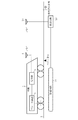
図2は指定停止位置までの距離と現在速度とに応じた停止パターンを示す説明図である。
【0008】
次に動作について説明する。
図1において、地上の送受信アンテナ14からは、軌道1上に向けて、常時、定間隔で通信波が送信されており、車両2が軌道1上を左から右に走行してきた場合に、車両の前面によりその通信波が反射され、地上の送受信アンテナ14により受信される。地上の送受信機13では、この通信波の送受信の時間差により、その地上の送受信アンテナ14の設置位置から車両2までの距離を測定する(距離測定工程)。このような距離の測定は、車両2が停止するまで連続的に複数回に渡って行われる。
【0009】
この地上の送受信機13および送受信アンテナ14は、従来の技術の地上子と異なり、使用する通信波により走行車両2と通信可能な場所であればどこにでも設置することができる。そこで、この送受信アンテナ14を指定停止位置に立てない場合には、送受信機13において、測定された地上の送受信アンテナ14の設置位置から車両2までの距離に、地上の送受信アンテナ14の設置位置から指定停止位置までの距離を加算演算し、地上の送受信アンテナ14および車上の受信アンテナ4間の通信回線を接続し、その加算した距離を測定距離として、地上の送受信アンテナ14から車上の受信アンテナ4に送信する(距離送信工程)。このような測定距離の送信は、距離が測定される都度、測定距離を送信する。なお、送受信アンテナ14を指定停止位置に立てた場合には、地上の送受信アンテナ14の設置位置から指定停止位置までの距離を加算演算することなく、測定された距離をそのまま送信すれば良い。
【0010】
車両2から指定停止位置までの距離は逐次、地上の送受信アンテナ14から車上の受信アンテナ4への通信回線により送信され、車上の受信機3により受信される。車上の受信機3では、受信された車両2から指定停止位置までの距離と、速度計(図示せず)による車両2の現在速度とに応じて、図2に示すような停止パターンを発生する。ここで、停止パターンとは、速度をどのように減少させて指定停止位置で停止させるかを示したものであり、図2において破線が理想曲線であり、これが停止パターンに相当するものである。また、実線は、実際に停止パターンが補正されながら車両2が停止した場合の曲線である。
車上の受信機3で発生された停止パターンは、ブレーキ装置5に伝送され、ブレーキ装置5ではその停止パターンに基づいて車両2のブレーキ力を制御する(車両停止工程)。なお、ブレーキ装置5により停止パターンに基づいて車両2のブレーキ力を制御すれば車両2の速度が低下するが、車上の受信機3では、逐次受信される車両2から指定停止位置までの距離と、刻々低下する車両2の現在速度とに応じて補正した停止パターンを逐次発生し、ブレーキ装置5では、それら逐次発生される補正した停止パターンに基づいて車両のブレーキ力を制御すことで、フィードバック制御が掛かり、理想に近い曲線で指定停止位置に車両2を停止させることができる。
車両2を停止すると、地上の送受信アンテナ14および車上の受信アンテナ4間の通信回線は切られる。
【0011】
以上のように、この実施の形態1によれば、距離測定工程による通信波の送受信の時間差により、地上の送受信アンテナ14の設置位置から車両2までの距離を測定することで、従来の速度計発電機による距離測定に比べて精度を高めることができる。
また、距離送信工程により地上の送受信アンテナ14から車上の受信アンテナ4に測定距離を送信することで、地上子設置の手間を省き、プラットホームの延長や編成車両数の変更等といった環境の変化に対しても経費を費やすことなく対応可能にすることができる。
さらに、地上の送受信アンテナ14の設置場所に関する制限は、地上子の設置場所に関する制限に比べて緩やかなので、設置に関しても経費を安くすることが望め、しかも地上子のように設置数も縛られることがなく、設置しやすくすることができる。
さらに、連続的に複数回に渡って距離測定し、停止パターンを決定し、それら停止パターンに基づいて車両のブレーキ力を制御するので、複数回に渡って停止パターンを補正することができ、急な減速等が生じることなく、乗り心地を向上させることができる。
【0012】
実施の形態2.
図3はこの発明の実施の形態2による軌道上を走行する車両を示す構成図であり、図において、車両2において、ブレーキ装置5、車上の送受信機6、車上の送受信アンテナ(アンテナ)7、車上の通信装置8を備え、また、地上の軌道1周辺において、送受信機13、送受信アンテナ14、通信装置15を備えている。
【0013】
次に動作について説明する。
図3において、地上の送受信アンテナ14からは、軌道1上に向けて、常時、定間隔で通信波が送信されている。車両2が軌道1上を左から右に走行してきた場合に、車両の前面に設けられた送受信アンテナ7によりその通信波が受信され、車上の送受信機6ではその受信された通信波を増幅して、送受信アンテナ7によりその増幅された通信波が地上の送受信アンテナ14方面に送信される。地上の送受信アンテナ14では、その通信波が受信される。このようにして、地上の送受信アンテナ14側から見た場合に、送信した通信波が車両の前面に設けられた送受信アンテナ7により反射されたものと同等に処理することができる。地上の送受信機13では、この通信波の送受信の時間差により、その地上の送受信アンテナ14の設置位置から車両2までの距離を測定する(距離測定工程)。このような距離の測定は、車両2が停止するまで連続的に複数回に渡って行われる。
なお、この実施の形態2においては、車上に送受信機6、送受信アンテナ7、通信装置8を備え、地上に送受信機13、送受信アンテナ14、通信装置15を備え、地上および車上の送受信アンテナ7,14間で送受信自在な通信回線が設けられており、上記距離測定工程における通信波の送受信は、その通信回線を利用して行われる。
【0014】
また、上記実施の形態1に示したように、車両2から指定停止位置までの距離演算を行い、その通信回線を利用してその演算した測定距離を、地上の送受信アンテナ14から車上の送受信アンテナ7に送信する(距離送信工程)。このような測定距離の送信は、距離が測定される都度、測定距離を送信する。
車両2から指定停止位置までの測定距離は逐次、車上の送受信アンテナ7に受信される。ここで、車上の送受信機6では、上記距離測定工程における増幅処理による遅延時間に応じた距離に基づいて測定距離を補正する。
すなわち、上記距離測定工程において、車上の送受信アンテナ7により直接に通信波を反射した場合と、車上の送受信アンテナ7により通信波を受信し、車上の送受信機6により増幅し、その送受信アンテナ7により送信した場合との差を遅延時間として予め送受信機6に記憶しておき、その送受信機6では、受信される測定距離からその遅延時間に応じた距離を差し引いた距離を車両2から指定停止位置までの距離とする。
以降、その車両2から指定停止位置までの距離と、車両2の現在速度とに応じて、ブレーキ装置5を制御するのは、実施の形態1と同等である(車両停止工程)。
【0015】
以上のように、この実施の形態2によれば、距離測定工程において、送受信アンテナ14により送信された通信波を、車両の前面に設けられた送受信アンテナ7により受信し、送受信機6ではその受信された通信波を増幅して、送受信アンテナ7によりその増幅された通信波を地上の送受信アンテナ14方面に送信するので、地上の送受信アンテナ14において受信される通信波の強度が微弱になることなく、送受信機13において距離測定に必要な通信波を確実に認識することができる。
また、距離測定工程における増幅処理による遅延時間を予め記憶しておき、車両停止工程において、その遅延時間に応じた距離に基づいて測定距離を補正するので、増幅処理による遅延時間が補正された精度の高い測定距離により車両2の停止制御を行うことができる。
さらに、地上および車上の送受信アンテナ7,14間で送受信自在な通信回線が設けられており、この通信回線は、距離送信工程での地上の送受信アンテナ14から車上の送受信アンテナ7への測定距離の送信に用いられるが、回線容量にはかなりの余裕があるため、その他の情報もその通信回線を用いて送信しても良い。
例えば、地上から車上に、地上の送受信アンテナ14の設置位置から指定停止位置までの距離を送信し、車上において地上の送受信アンテナ14の設置位置から車両2までの距離に地上の送受信アンテナ14の設置位置から指定停止位置までの距離を加えて、車両2から指定停止位置までの距離を求めるようにしても良い。この場合、地上の送受信機13における加算演算を削減することができる。また、緊急情報等を送信するようにしても良い。例えば、地上から車上に、プラットホームの設備の故障情報やプラットホームの画像を送信したり、車上から地上に、車上の病人等の情報を送信したりするようにしても良い。
【0016】
実施の形態3.
図4はこの発明の実施の形態3による軌道上を走行する車両を示す構成図であり、図において、軌道回路21は、地上の軌道に沿って設けられ、車両2を検知する走行車両検知システムを構成するものである。その他の構成については、図1と同一である。
【0017】
次に動作について説明する。
この実施の形態3では、上記実施の形態1に示した構成において、車両2を検知する軌道回路21からなる走行車両検知システムを備えたものである。
車両2が軌道1上を左から右に走行してきた場合に、走行車両検知システムにより車両2の進入を検出し、送受信機13にその情報を伝送する(車両進入検出工程)。
そして、地上の送受信機13および送受信アンテナ14は、通常は電源を停止しているが、走行車両検知システムからの車両2の進入検出に応じて、電源を供給し、地上の送受信アンテナ14から送信し、車上の前面により反射され、地上の送受信アンテナ14により受信された通信波の送受信の時間差により、地上の送受信アンテナ14の設置位置から車両2までの距離を測定する(距離測定工程)。
また、走行車両検知システムにより検出される車両2の進入により想定される地上の送受信アンテナ14の設置位置から車両2までの距離に基づいて、距離測定工程において測定される地上の送受信アンテナ14の設置位置から車両2までの距離を校正する(測定距離校正工程)。
【0018】
以上のように、この実施の形態3によれば、地上の軌道1に沿って車両2を検知する軌道回路21からなる走行車両検知システムを備え、走行車両検知システムからの車両2の進入検出に応じて、地上の送受信機13および送受信アンテナ14は、電源を供給し、地上の送受信アンテナ14の設置位置から車両2までの距離を測定するようにしたので、車両2の進入に同期して距離測定やその送信動作を行うことができ、地上設備の省電力化ができる。
また、走行車両検知システムにより検出される車両2の進入により想定される地上の送受信アンテナ14の設置位置から車両2までの距離と、通信波の送受信の時間差による測定距離とを比較することにより、距離測定機能の校正を行うことができる。
【0019】
【発明の効果】
以上のように、この発明によれば、距離測定工程による通信波の送受信の時間差により、地上のアンテナの設置位置から車両までの距離を測定することで、従来の速度計発電機による距離測定に比べて精度を高めることができる。また、距離送信工程により地上のアンテナから車両のアンテナに測定距離を送信することで、地上子設置の手間を省き、プラットホームの延長や編成車両数の変更等といった環境の変化に対しても経費を費やすことなく対応可能にすることができる。さらに、地上のアンテナの設置場所に関する制限は、地上子の設置場所に関する制限に比べて緩やかなので、設置に関しても経費を安くすることが望め、しかも地上子のように設置数も縛られることがなく、設置しやすい効果がある。
また、距離測定工程において、地上のアンテナにより送信された通信波を、車両に設けられたアンテナにより受信し、その受信された通信波を増幅して、車両に設けられたアンテナによりその増幅された通信波を地上のアンテナ方面に送信するので、地上のアンテナにおいて受信される通信波の強度が微弱になることなく、距離測定に必要な通信波を確実に認識することができる効果がある。
さらに、車両停止工程は、距離測定工程において、車両に設けられたアンテナにより直接に通信波を反射した場合と、車両に設けられたアンテナにより通信波を受信し、その受信された通信波を増幅して、車両に設けられたアンテナにより送信した場合との時間差を遅延時間として、受信される測定距離からその遅延時間に応じた距離を差し引いた距離を車両から指定停止位置までの距離とするようにしたので、増幅処理による遅延時間が補正された精度の高い測定距離により車両の停止制御を行うことができる効果がある。
【図面の簡単な説明】
【図1】 この発明の実施の形態1による軌道上を走行する車両を示す構成図である。
【図2】 指定停止位置までの距離と現在速度とに応じた停止パターンを示す説明図である。
【図3】 この発明の実施の形態2による軌道上を走行する車両を示す構成図である。
【図4】 この発明の実施の形態3による軌道上を走行する車両を示す構成図である。
【符号の説明】
1 軌道、2 車両、3 受信機、4 受信アンテナ(アンテナ)、5 ブレーキ装置、6,13 送受信機、7,14 送受信アンテナ(アンテナ)、8,15 通信装置、21 軌道回路。[0001]
BACKGROUND OF THE INVENTION
The present invention relates to a communication wave type fixed position stop control method for performing fixed position stop control of a traveling vehicle using a communication wave in an orbital traffic system.
[0002]
[Prior art]
Train position detection, which is important in conventional automatic train operation (ATO) for railways and pattern control, is carried out by distance calculation using a speedometer generator (tacho generator) installed on the vehicle, ground unit and vehicle unit. Detects the current position due to the changing action by the vehicle, the speed and distance calculation by the acceleration detection by the rate gyro provided on the vehicle, and the map data. There was what corrected a train position by a result (for example, patent documents 1).
Here, the vehicle upper element is configured by an oscillator or the like, and emits radio waves immediately below and receives reflected radio waves. The ground element is configured by a coil or the like and is located at a predetermined position. It is installed and reflected by changing the frequency of the radio wave emitted from the vehicle upper element to the frequency unique to the ground element (frequency changing action). Therefore, the installation position of the ground element and the reflected frequency are recognized in advance on the upper side of the vehicle, and the train position is detected from the frequency of the radio wave received by the vehicle element when the train passes over the ground element. .
[0003]
[Patent Document 1]
Japanese Patent Laid-Open No. 2000-247235
[Problems to be solved by the invention]
Since the conventional train position detection method is configured as described above, there are the following problems.
Along with the automation of train stop control, a ground element and a vehicle upper element are provided to detect the current position of the train with high accuracy, but the brake is applied between the point where the train first starts braking and the specified stop position. It is customary to correct the movement. Therefore, it was necessary to install a plurality of ground elements for correcting the brake operation.
In addition, if there is a platform extension work to increase transportation capacity or the number of trains is changed depending on the operating hours, the designated stop position will be changed, and the designated stop position will be changed. Therefore, it was necessary to install multiple ground units.
Furthermore, even if a plurality of ground elements are installed in this way, the braking operation can be corrected on the vehicle only at each point where the ground elements are installed. As a result, the train stop control can be realized only by the point control. Therefore, in some cases, sudden deceleration occurs at the correction point of the brake operation, which adversely affects riding comfort.
[0005]
The present invention has been made to solve the above-described problems, and the parameters required for the fixed position stop control, in particular, the measurement distance is transmitted from the ground to the vehicle using a communication wave, thereby improving the distance measurement accuracy. In addition, a communication wave type fixed position stop control method capable of responding to changes in the environment, such as extending the platform and changing the number of trains, without spending time, is also possible. Objective.
[0006]
[Means for Solving the Problems]
A communication wave type fixed position stop control method according to the present invention is transmitted from an antenna provided around a track on the ground, received by an antenna provided on a vehicle, amplifies the received communication wave, The amplified communication wave is transmitted to the ground antenna direction by the installed antenna, and the distance from the ground antenna installation position to the vehicle according to the time difference due to transmission and reception of the communication wave received by the ground antenna A distance measurement step for measuring the distance, a distance transmission step for transmitting a measurement distance from an antenna on the ground to an antenna provided on the vehicle, and a designated stop position depending on the received measurement distance and the current speed of the vehicle. distance and determines a stop pattern corresponding to the current speed, and a vehicle stopping step of controlling the braking force of the vehicle based on the stop pattern, the vehicle stop process, the distance In the fixing process, when the communication wave is directly reflected by the antenna provided in the vehicle, the communication wave is received by the antenna provided in the vehicle, and the received communication wave is amplified and provided in the vehicle. A time difference from the case of transmission by an antenna is set as a delay time, and a distance obtained by subtracting a distance corresponding to the delay time from a received measurement distance is set as a distance from the vehicle to a designated stop position .
[0007]
DETAILED DESCRIPTION OF THE INVENTION
An embodiment of the present invention will be described below.
FIG. 1 is a configuration diagram showing a vehicle traveling on a track according to
FIG. 2 is an explanatory diagram showing stop patterns according to the distance to the designated stop position and the current speed.
[0008]
Next, the operation will be described.
In FIG. 1, when a communication wave is constantly transmitted from the ground transmitting / receiving
[0009]
The
[0010]
The distance from the
The stop pattern generated by the receiver 3 on the vehicle is transmitted to the
When the
[0011]
As described above, according to the first embodiment, the conventional speedometer is measured by measuring the distance from the installation position of the transmission /
In addition, by transmitting the measurement distance from the ground transmitting / receiving
Furthermore, since the restrictions on the installation location of the ground transmitting / receiving
Furthermore, since the distance is measured continuously several times, the stop pattern is determined, and the braking force of the vehicle is controlled based on these stop patterns, the stop pattern can be corrected several times, Riding comfort can be improved without causing slow deceleration or the like.
[0012]
FIG. 3 is a block diagram showing a vehicle traveling on a track according to
[0013]
Next, the operation will be described.
In FIG. 3, communication waves are constantly transmitted from the ground transmitting / receiving
In the second embodiment, the transmitter / receiver 6, the transmitter / receiver antenna 7, and the
[0014]
Further, as shown in the first embodiment, distance calculation from the
The measurement distance from the
That is, in the distance measuring step, when the communication wave is directly reflected by the transmission / reception antenna 7 on the vehicle, the communication wave is received by the transmission / reception antenna 7 on the vehicle, amplified by the transceiver 6 on the vehicle, and transmitted / received. The difference from the case of transmission by the antenna 7 is stored in advance in the transmitter / receiver 6 as a delay time. In the transmitter / receiver 6, the distance obtained by subtracting the distance corresponding to the delay time from the measured distance is received from the
Thereafter, controlling the
[0015]
As described above, according to the second embodiment, in the distance measurement step, the communication wave transmitted by the transmission /
In addition, since the delay time due to the amplification process in the distance measurement process is stored in advance and the measurement distance is corrected based on the distance according to the delay time in the vehicle stop process, the accuracy in which the delay time due to the amplification process is corrected The stop control of the
Further, a communication line that can be transmitted and received between the transmission and
For example, the distance from the installation position of the transmission /
[0016]
Embodiment 3 FIG.
4 is a block diagram showing a vehicle traveling on a track according to a third embodiment of the present invention. In the figure, a
[0017]
Next, the operation will be described.
In the third embodiment, the traveling vehicle detection system including the
When the
The ground transmitter /
Also, the installation of the ground transmission /
[0018]
As described above, according to the third embodiment, the traveling vehicle detection system including the
Moreover, by comparing the distance from the installation position of the transmission /
[0019]
【The invention's effect】
As described above, according to the present invention, the distance from the installation position of the ground antenna to the vehicle is measured by the time difference of transmission and reception of the communication wave in the distance measurement process, so that the conventional speedometer generator can measure the distance. Compared with the accuracy can be increased. In addition, by transmitting the measurement distance from the ground antenna to the vehicle antenna by the distance transmission process, it saves the trouble of installing the ground unit and also saves expenses for environmental changes such as platform extension and number of trains. It can be made available without spending. Furthermore, the restrictions on the installation location of the antenna on the ground are more relaxed than the restrictions on the installation location of the ground element, so it is possible to reduce the cost of the installation, and the number of installations is not restricted like the ground element. It is easy to install.
Further, in the distance measurement step, the communication wave transmitted from the ground antenna is received by the antenna provided in the vehicle, the received communication wave is amplified, and is amplified by the antenna provided in the vehicle. Since the communication wave is transmitted toward the ground antenna, there is an effect that the communication wave required for the distance measurement can be surely recognized without weakening the intensity of the communication wave received by the ground antenna.
Further, in the vehicle stopping process, in the distance measurement process, when the communication wave is directly reflected by the antenna provided in the vehicle, the communication wave is received by the antenna provided in the vehicle, and the received communication wave is amplified. Then, the time difference from the case of transmission by the antenna provided in the vehicle is set as the delay time, and the distance obtained by subtracting the distance corresponding to the delay time from the received measurement distance is set as the distance from the vehicle to the designated stop position. Therefore, there is an effect that the stop control of the vehicle can be performed with a highly accurate measurement distance in which the delay time by the amplification process is corrected.
[Brief description of the drawings]
FIG. 1 is a configuration diagram showing a vehicle traveling on a track according to
FIG. 2 is an explanatory diagram showing stop patterns according to a distance to a designated stop position and a current speed.
FIG. 3 is a configuration diagram showing a vehicle traveling on a track according to a second embodiment of the present invention.
FIG. 4 is a configuration diagram showing a vehicle traveling on a track according to a third embodiment of the present invention.
[Explanation of symbols]
1 track, 2 vehicles, 3 receivers, 4 receiving antennas (antennas), 5 brake devices, 6, 13 transceivers, 7, 14 transmitting / receiving antennas (antennas), 8, 15 communication devices, 21 track circuits.
Claims (5)
上記地上のアンテナから上記車両に設けられたアンテナに、測定距離を送信する距離送信工程と、
受信された測定距離と車両の現在速度とに応じて、指定停止位置までの距離と現在速度とに応じた停止パターンを決定し、その停止パターンに基づいて車両のブレーキ力を制御する車両停止工程とを備え、
上記車両停止工程は、上記距離測定工程において、車両に設けられたアンテナにより直接に通信波を反射した場合と、車両に設けられたアンテナにより通信波を受信し、その受信された通信波を増幅して、車両に設けられたアンテナにより送信した場合との時間差を遅延時間として、受信される測定距離からその遅延時間に応じた距離を差し引いた距離を車両から指定停止位置までの距離とすることを特徴とする通信波式定位置停止制御方法。The signal is transmitted from an antenna provided around the track on the ground, received by the antenna provided on the vehicle, the received communication wave is amplified, and the amplified communication wave is received by the antenna provided on the vehicle. A distance measuring step of measuring the distance from the installation position of the antenna on the ground to the vehicle according to the time difference due to transmission and reception of the communication wave transmitted to the antenna direction and received by the antenna on the ground,
A distance transmission step of transmitting a measurement distance from the ground antenna to an antenna provided in the vehicle;
A vehicle stop process for determining a stop pattern according to the distance to the designated stop position and the current speed according to the received measurement distance and the current speed of the vehicle, and controlling the braking force of the vehicle based on the stop pattern It equipped with a door,
In the vehicle stop step, the communication wave is directly reflected by the antenna provided in the vehicle in the distance measurement step, and the communication wave is received by the antenna provided in the vehicle, and the received communication wave is amplified. Then, let the time difference from the case of transmitting by the antenna provided in the vehicle be the delay time, and the distance obtained by subtracting the distance corresponding to the delay time from the received measurement distance is the distance from the vehicle to the designated stop position The communication wave type fixed position stop control method characterized by this .
距離測定工程は、車両の進入が検出された場合に、地上に設けられたアンテナから通信波を送信し、その地上のアンテナの設置位置から車両までの距離の測定を開始することを特徴とする請求項1記載の通信波式定位置停止制御方法。A vehicle entry detection step of detecting entry of a vehicle by a traveling vehicle detection system comprising a track circuit that detects the vehicle along a track on the ground;
The distance measurement step is characterized in that when an approach of a vehicle is detected, a communication wave is transmitted from an antenna provided on the ground, and measurement of the distance from the installation position of the ground antenna to the vehicle is started. claim 1 Symbol placement of communication wave type fixed-position stop control method.
距離送信工程は、距離が測定される都度、測定距離を送信し、
車両停止工程は、測定距離が受信される都度、その受信された測定距離と車両の現在速度とに応じて、指定停止位置までの距離と現在速度とに応じた停止パターンを決定し、その停止パターンに基づいて車両のブレーキ力を制御することを特徴とする請求項1から請求項3のうちのいずれか1項記載の通信波式定位置停止制御方法。The distance measurement process continuously measures the distance from the installation position of the antenna on the ground to the vehicle over multiple times,
The distance transmission process transmits the measurement distance every time the distance is measured,
Each time the measurement distance is received, the vehicle stop process determines a stop pattern according to the distance to the designated stop position and the current speed according to the received measurement distance and the current speed of the vehicle, and stops the vehicle. The communication wave type fixed position stop control method according to any one of claims 1 to 3 , wherein the braking force of the vehicle is controlled based on the pattern.
Priority Applications (1)
| Application Number | Priority Date | Filing Date | Title |
|---|---|---|---|
| JP2003015052A JP4125143B2 (en) | 2003-01-23 | 2003-01-23 | Communication wave type fixed position stop control method |
Applications Claiming Priority (1)
| Application Number | Priority Date | Filing Date | Title |
|---|---|---|---|
| JP2003015052A JP4125143B2 (en) | 2003-01-23 | 2003-01-23 | Communication wave type fixed position stop control method |
Publications (2)
| Publication Number | Publication Date |
|---|---|
| JP2004224220A JP2004224220A (en) | 2004-08-12 |
| JP4125143B2 true JP4125143B2 (en) | 2008-07-30 |
Family
ID=32902917
Family Applications (1)
| Application Number | Title | Priority Date | Filing Date |
|---|---|---|---|
| JP2003015052A Expired - Fee Related JP4125143B2 (en) | 2003-01-23 | 2003-01-23 | Communication wave type fixed position stop control method |
Country Status (1)
| Country | Link |
|---|---|
| JP (1) | JP4125143B2 (en) |
Families Citing this family (5)
| Publication number | Priority date | Publication date | Assignee | Title |
|---|---|---|---|---|
| JP4931748B2 (en) * | 2007-09-21 | 2012-05-16 | 三菱電機株式会社 | Train position detection device and mobile radio |
| JP6198933B2 (en) | 2014-09-05 | 2017-09-20 | 三菱電機株式会社 | Automatic train operation system and brake control device |
| WO2017018021A1 (en) * | 2015-07-27 | 2017-02-02 | 株式会社日立国際電気 | Distance measuring device and radio communication system |
| KR101709098B1 (en) * | 2015-11-06 | 2017-02-24 | (주)컨버전스스퀘어 | System and method for providing information of running train |
| JP7300960B2 (en) * | 2019-10-15 | 2023-06-30 | 株式会社日立製作所 | Sensor soundness confirmation system and railway vehicle |
-
2003
- 2003-01-23 JP JP2003015052A patent/JP4125143B2/en not_active Expired - Fee Related
Also Published As
| Publication number | Publication date |
|---|---|
| JP2004224220A (en) | 2004-08-12 |
Similar Documents
| Publication | Publication Date | Title |
|---|---|---|
| US9022325B2 (en) | Train control system | |
| US9278702B2 (en) | Train control system | |
| US9663125B2 (en) | Train control system | |
| US9505420B2 (en) | Train control system | |
| JP2013023054A (en) | Train control system | |
| JP4945286B2 (en) | Train position detector | |
| EP2614983A2 (en) | Train control system | |
| KR20140088891A (en) | Train position detection system | |
| US5903517A (en) | Moving body control apparatus | |
| JP4125143B2 (en) | Communication wave type fixed position stop control method | |
| JP2008253034A (en) | Train control device | |
| US20210139053A1 (en) | On-board control apparatus and platform-door control system | |
| WO2018092307A1 (en) | Communication control device, toll collection system, communication control method, and program | |
| JP4926213B2 (en) | Train control device | |
| JP5412482B2 (en) | Train position detector | |
| KR101210439B1 (en) | Emergency brake control apparatus and method | |
| JP5398500B2 (en) | Train control device | |
| JP4931951B2 (en) | Train position detection device | |
| CZ63298A3 (en) | Determination method of railway vehicle velocity and apparatus for making the same | |
| JP4053959B2 (en) | Fixed position stop controller | |
| JPH0532166A (en) | Train position sensing device | |
| CN109789791B (en) | Vehicle-mounted device and emergency braking control method | |
| JPH092269A (en) | Train position detecting device | |
| KR100837163B1 (en) | Marker detecting system and marker detecting method using thereof | |
| JP2003108227A (en) | Tracking method and apparatus for automated carrying facility |
Legal Events
| Date | Code | Title | Description |
|---|---|---|---|
| A621 | Written request for application examination |
Free format text: JAPANESE INTERMEDIATE CODE: A621 Effective date: 20050107 |
|
| A131 | Notification of reasons for refusal |
Free format text: JAPANESE INTERMEDIATE CODE: A131 Effective date: 20071002 |
|
| A521 | Written amendment |
Free format text: JAPANESE INTERMEDIATE CODE: A821 Effective date: 20071119 |
|
| RD02 | Notification of acceptance of power of attorney |
Free format text: JAPANESE INTERMEDIATE CODE: A7422 Effective date: 20071119 |
|
| RD04 | Notification of resignation of power of attorney |
Free format text: JAPANESE INTERMEDIATE CODE: A7424 Effective date: 20071119 |
|
| A521 | Written amendment |
Free format text: JAPANESE INTERMEDIATE CODE: A523 Effective date: 20071130 |
|
| A131 | Notification of reasons for refusal |
Free format text: JAPANESE INTERMEDIATE CODE: A131 Effective date: 20080108 |
|
| A521 | Written amendment |
Free format text: JAPANESE INTERMEDIATE CODE: A523 Effective date: 20080307 |
|
| TRDD | Decision of grant or rejection written | ||
| A01 | Written decision to grant a patent or to grant a registration (utility model) |
Free format text: JAPANESE INTERMEDIATE CODE: A01 Effective date: 20080408 |
|
| A01 | Written decision to grant a patent or to grant a registration (utility model) |
Free format text: JAPANESE INTERMEDIATE CODE: A01 |
|
| A61 | First payment of annual fees (during grant procedure) |
Free format text: JAPANESE INTERMEDIATE CODE: A61 Effective date: 20080507 |
|
| R150 | Certificate of patent or registration of utility model |
Free format text: JAPANESE INTERMEDIATE CODE: R150 |
|
| FPAY | Renewal fee payment (event date is renewal date of database) |
Free format text: PAYMENT UNTIL: 20110516 Year of fee payment: 3 |
|
| FPAY | Renewal fee payment (event date is renewal date of database) |
Free format text: PAYMENT UNTIL: 20110516 Year of fee payment: 3 |
|
| FPAY | Renewal fee payment (event date is renewal date of database) |
Free format text: PAYMENT UNTIL: 20120516 Year of fee payment: 4 |
|
| LAPS | Cancellation because of no payment of annual fees |