WO2021215413A1 - プリフォーム、殺菌装置および殺菌方法 - Google Patents
プリフォーム、殺菌装置および殺菌方法 Download PDFInfo
- Publication number
- WO2021215413A1 WO2021215413A1 PCT/JP2021/015934 JP2021015934W WO2021215413A1 WO 2021215413 A1 WO2021215413 A1 WO 2021215413A1 JP 2021015934 W JP2021015934 W JP 2021015934W WO 2021215413 A1 WO2021215413 A1 WO 2021215413A1
- Authority
- WO
- WIPO (PCT)
- Prior art keywords
- axis
- preform
- along
- spout
- electron beam
- Prior art date
- Legal status (The legal status is an assumption and is not a legal conclusion. Google has not performed a legal analysis and makes no representation as to the accuracy of the status listed.)
- Ceased
Links
Images

Classifications
-
- B—PERFORMING OPERATIONS; TRANSPORTING
- B29—WORKING OF PLASTICS; WORKING OF SUBSTANCES IN A PLASTIC STATE IN GENERAL
- B29C—SHAPING OR JOINING OF PLASTICS; SHAPING OF MATERIAL IN A PLASTIC STATE, NOT OTHERWISE PROVIDED FOR; AFTER-TREATMENT OF THE SHAPED PRODUCTS, e.g. REPAIRING
- B29C49/00—Blow-moulding, i.e. blowing a preform or parison to a desired shape within a mould; Apparatus therefor
- B29C49/071—Preforms or parisons characterised by their configuration, e.g. geometry, dimensions or physical properties
-
- A—HUMAN NECESSITIES
- A61—MEDICAL OR VETERINARY SCIENCE; HYGIENE
- A61L—METHODS OR APPARATUS FOR STERILISING MATERIALS OR OBJECTS IN GENERAL; DISINFECTION, STERILISATION OR DEODORISATION OF AIR; CHEMICAL ASPECTS OF BANDAGES, DRESSINGS, ABSORBENT PADS OR SURGICAL ARTICLES; MATERIALS FOR BANDAGES, DRESSINGS, ABSORBENT PADS OR SURGICAL ARTICLES
- A61L2/00—Disinfection or sterilisation of materials or objects, in general; Accessories therefor
- A61L2/02—Disinfection or sterilisation of materials or objects, in general; Accessories therefor using physical processes
- A61L2/08—Radiation
- A61L2/087—Particle radiation, e.g. electron-beam, alpha or beta radiation
-
- B—PERFORMING OPERATIONS; TRANSPORTING
- B29—WORKING OF PLASTICS; WORKING OF SUBSTANCES IN A PLASTIC STATE IN GENERAL
- B29C—SHAPING OR JOINING OF PLASTICS; SHAPING OF MATERIAL IN A PLASTIC STATE, NOT OTHERWISE PROVIDED FOR; AFTER-TREATMENT OF THE SHAPED PRODUCTS, e.g. REPAIRING
- B29C49/00—Blow-moulding, i.e. blowing a preform or parison to a desired shape within a mould; Apparatus therefor
- B29C49/42—Component parts, details or accessories; Auxiliary operations
- B29C49/42414—Treatment of preforms, e.g. cleaning or spraying water for improved heat transfer
- B29C49/42416—Purging or cleaning the preforms
- B29C49/42418—Purging or cleaning the preforms for sterilizing
-
- A—HUMAN NECESSITIES
- A61—MEDICAL OR VETERINARY SCIENCE; HYGIENE
- A61L—METHODS OR APPARATUS FOR STERILISING MATERIALS OR OBJECTS IN GENERAL; DISINFECTION, STERILISATION OR DEODORISATION OF AIR; CHEMICAL ASPECTS OF BANDAGES, DRESSINGS, ABSORBENT PADS OR SURGICAL ARTICLES; MATERIALS FOR BANDAGES, DRESSINGS, ABSORBENT PADS OR SURGICAL ARTICLES
- A61L2103/00—Materials or objects being the target of disinfection or sterilisation
- A61L2103/23—Containers other than laboratory or medical, e.g. bottles or mail
-
- B—PERFORMING OPERATIONS; TRANSPORTING
- B29—WORKING OF PLASTICS; WORKING OF SUBSTANCES IN A PLASTIC STATE IN GENERAL
- B29C—SHAPING OR JOINING OF PLASTICS; SHAPING OF MATERIAL IN A PLASTIC STATE, NOT OTHERWISE PROVIDED FOR; AFTER-TREATMENT OF THE SHAPED PRODUCTS, e.g. REPAIRING
- B29C2949/00—Indexing scheme relating to blow-moulding
- B29C2949/07—Preforms or parisons characterised by their configuration
- B29C2949/0715—Preforms or parisons characterised by their configuration the preform having one end closed
-
- B—PERFORMING OPERATIONS; TRANSPORTING
- B29—WORKING OF PLASTICS; WORKING OF SUBSTANCES IN A PLASTIC STATE IN GENERAL
- B29C—SHAPING OR JOINING OF PLASTICS; SHAPING OF MATERIAL IN A PLASTIC STATE, NOT OTHERWISE PROVIDED FOR; AFTER-TREATMENT OF THE SHAPED PRODUCTS, e.g. REPAIRING
- B29C2949/00—Indexing scheme relating to blow-moulding
- B29C2949/07—Preforms or parisons characterised by their configuration
- B29C2949/076—Preforms or parisons characterised by their configuration characterised by the shape
- B29C2949/0761—Preforms or parisons characterised by their configuration characterised by the shape characterised by overall the shape
- B29C2949/0762—Conical
-
- B—PERFORMING OPERATIONS; TRANSPORTING
- B29—WORKING OF PLASTICS; WORKING OF SUBSTANCES IN A PLASTIC STATE IN GENERAL
- B29C—SHAPING OR JOINING OF PLASTICS; SHAPING OF MATERIAL IN A PLASTIC STATE, NOT OTHERWISE PROVIDED FOR; AFTER-TREATMENT OF THE SHAPED PRODUCTS, e.g. REPAIRING
- B29C2949/00—Indexing scheme relating to blow-moulding
- B29C2949/07—Preforms or parisons characterised by their configuration
- B29C2949/076—Preforms or parisons characterised by their configuration characterised by the shape
- B29C2949/0768—Preforms or parisons characterised by their configuration characterised by the shape characterised by the shape of specific parts of preform
- B29C2949/077—Preforms or parisons characterised by their configuration characterised by the shape characterised by the shape of specific parts of preform characterised by the neck
- B29C2949/0772—Closure retaining means
- B29C2949/0773—Threads
-
- B—PERFORMING OPERATIONS; TRANSPORTING
- B29—WORKING OF PLASTICS; WORKING OF SUBSTANCES IN A PLASTIC STATE IN GENERAL
- B29C—SHAPING OR JOINING OF PLASTICS; SHAPING OF MATERIAL IN A PLASTIC STATE, NOT OTHERWISE PROVIDED FOR; AFTER-TREATMENT OF THE SHAPED PRODUCTS, e.g. REPAIRING
- B29C2949/00—Indexing scheme relating to blow-moulding
- B29C2949/07—Preforms or parisons characterised by their configuration
- B29C2949/076—Preforms or parisons characterised by their configuration characterised by the shape
- B29C2949/0768—Preforms or parisons characterised by their configuration characterised by the shape characterised by the shape of specific parts of preform
- B29C2949/0778—Preforms or parisons characterised by their configuration characterised by the shape characterised by the shape of specific parts of preform characterised by the flange
-
- B—PERFORMING OPERATIONS; TRANSPORTING
- B29—WORKING OF PLASTICS; WORKING OF SUBSTANCES IN A PLASTIC STATE IN GENERAL
- B29C—SHAPING OR JOINING OF PLASTICS; SHAPING OF MATERIAL IN A PLASTIC STATE, NOT OTHERWISE PROVIDED FOR; AFTER-TREATMENT OF THE SHAPED PRODUCTS, e.g. REPAIRING
- B29C2949/00—Indexing scheme relating to blow-moulding
- B29C2949/07—Preforms or parisons characterised by their configuration
- B29C2949/076—Preforms or parisons characterised by their configuration characterised by the shape
- B29C2949/0768—Preforms or parisons characterised by their configuration characterised by the shape characterised by the shape of specific parts of preform
- B29C2949/078—Preforms or parisons characterised by their configuration characterised by the shape characterised by the shape of specific parts of preform characterised by the bottom
-
- B—PERFORMING OPERATIONS; TRANSPORTING
- B29—WORKING OF PLASTICS; WORKING OF SUBSTANCES IN A PLASTIC STATE IN GENERAL
- B29C—SHAPING OR JOINING OF PLASTICS; SHAPING OF MATERIAL IN A PLASTIC STATE, NOT OTHERWISE PROVIDED FOR; AFTER-TREATMENT OF THE SHAPED PRODUCTS, e.g. REPAIRING
- B29C2949/00—Indexing scheme relating to blow-moulding
- B29C2949/20—Preforms or parisons whereby a specific part is made of only one component, e.g. only one layer
- B29C2949/22—Preforms or parisons whereby a specific part is made of only one component, e.g. only one layer at neck portion
-
- B—PERFORMING OPERATIONS; TRANSPORTING
- B29—WORKING OF PLASTICS; WORKING OF SUBSTANCES IN A PLASTIC STATE IN GENERAL
- B29C—SHAPING OR JOINING OF PLASTICS; SHAPING OF MATERIAL IN A PLASTIC STATE, NOT OTHERWISE PROVIDED FOR; AFTER-TREATMENT OF THE SHAPED PRODUCTS, e.g. REPAIRING
- B29C2949/00—Indexing scheme relating to blow-moulding
- B29C2949/20—Preforms or parisons whereby a specific part is made of only one component, e.g. only one layer
- B29C2949/24—Preforms or parisons whereby a specific part is made of only one component, e.g. only one layer at flange portion
-
- B—PERFORMING OPERATIONS; TRANSPORTING
- B29—WORKING OF PLASTICS; WORKING OF SUBSTANCES IN A PLASTIC STATE IN GENERAL
- B29C—SHAPING OR JOINING OF PLASTICS; SHAPING OF MATERIAL IN A PLASTIC STATE, NOT OTHERWISE PROVIDED FOR; AFTER-TREATMENT OF THE SHAPED PRODUCTS, e.g. REPAIRING
- B29C2949/00—Indexing scheme relating to blow-moulding
- B29C2949/20—Preforms or parisons whereby a specific part is made of only one component, e.g. only one layer
- B29C2949/26—Preforms or parisons whereby a specific part is made of only one component, e.g. only one layer at body portion
-
- B—PERFORMING OPERATIONS; TRANSPORTING
- B29—WORKING OF PLASTICS; WORKING OF SUBSTANCES IN A PLASTIC STATE IN GENERAL
- B29C—SHAPING OR JOINING OF PLASTICS; SHAPING OF MATERIAL IN A PLASTIC STATE, NOT OTHERWISE PROVIDED FOR; AFTER-TREATMENT OF THE SHAPED PRODUCTS, e.g. REPAIRING
- B29C2949/00—Indexing scheme relating to blow-moulding
- B29C2949/20—Preforms or parisons whereby a specific part is made of only one component, e.g. only one layer
- B29C2949/28—Preforms or parisons whereby a specific part is made of only one component, e.g. only one layer at bottom portion
Definitions
- This disclosure relates to preforms, sterilizers and sterilization methods.
- an electron beam sterilizer that irradiates a preform of a container before blow molding with an electron beam to sterilize it is known (see, for example, Patent Document 1).
- the electron beam sterilizer disclosed in Patent Document 1 inserts an electron beam irradiation nozzle into the preform by raising and lowering the preform with respect to a fixed axial electron beam irradiation nozzle using an elevating device. It is a thing.
- the electron beam sterilizer disclosed in Patent Document 1 sterilizes the inner surface of the preform by irradiating the inner surface of the preform with an electron beam in a state where the electron beam irradiation nozzle is inserted inside the preform. ..
- the electron beam sterilizer disclosed in the patent document requires an elevating device for raising and lowering the preform with respect to the electron beam irradiation nozzle, the manufacturing cost of the electron beam sterilizer increases. In addition, since it takes time to move the preform up and down with respect to the electron beam irradiation nozzle, the time required to sterilize the preform becomes long.
- the present disclosure has been made in view of such circumstances, and when the preform is sterilized by irradiating it with an electron beam, the absorbed dose of the electron beam on the bottom side of the preform is sufficiently secured. It is an object of the present invention to provide a preform, a sterilizer, and a sterilization method capable of preventing an excessive absorbed dose of an electron beam on the spout side of the preform.
- the preform according to one aspect of the present disclosure is formed in a cylindrical shape along an axis and has an open end, and is formed in a cylindrical shape along the axis and is connected to the plug.
- a body portion and a bottom portion connected to the body portion and one end closed along the axis line are provided, and the body portion is connected to the spout portion and is radially orthogonal to the axis line.
- the second inner diameter in the radial direction gradually decreases with a constant gradient from the straight portion to the bottom portion, and the inclined portion has an inclination angle of an inner peripheral surface with respect to the axis of 12. It is formed so as to be greater than or equal to the degree and less than or equal to 22 degrees.
- the sterilization method sterilizes a preform, and the preform is formed in a cylindrical shape along an axis and has a spout portion having an open end and a cylindrical shape along the axis. It includes a body portion that is formed and connected to the spout portion, and a bottom portion that is connected to the body portion and has one end closed along the axis, and the body portion is connected to the spout portion.
- the first inner diameter in the radial direction orthogonal to the axis is constant at each position along the axis, and one end along the axis is connected to the spout and along the axis.
- the other end is connected to the bottom portion, and the inclined portion has an inclined portion in which the second inner diameter in the radial direction gradually decreases with a constant gradient from the spout portion to the bottom portion along the axis. Is formed so that the inclination angle of the inner peripheral surface with respect to the axis is 12 degrees or more and 22 degrees or less, and the transport step of transporting the preform along the transport direction intersecting the axis, and the transport. In the transport path in which the preform is conveyed by the step, an irradiation step of irradiating an electron beam in a direction along the axis toward the spout portion of the preform is provided.
- the absorbed dose of the electron beam on the bottom side of the preform is sufficiently secured and the electron beam on the spout side of the preform is sufficiently secured.
- Preforms, sterilizers and sterilization methods that can prevent excessive absorbed doses can be provided.
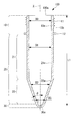
- FIG. 1 is a vertical cross-sectional view of the preform 100 according to the embodiment of the present disclosure.
- the preform 100 of the present embodiment is a tubular member having a bottom integrally molded with a thermoplastic resin material which is a main material, and is a member for producing a plastic bottle by blow molding.
- the thermoplastic resin material used in the preform 100 is, for example, PE (polyethylene), PP (polypropylene), PET (polyethylene terephthalate), PEN (polyethylene naphthalate), and PC (polycarbonate).
- the preform 100 of the present embodiment includes a spout portion 10, a body portion 20, and a bottom portion 30.
- the spout portion 10, the body portion 20, and the bottom portion 30 are integrally molded of a thermoplastic resin material.
- the preform 100 has a shape that extends along the axis X, one end on the spout portion 10 side is open, and the other end on the bottom 30 side is closed.
- the inner diameter D0 of the inner peripheral surface 10a of the spout portion 10 is constant at each position along the axis X.
- the length along the axis X from the end 100a on the spout portion 10 side of the preform 100 to the position where the inner peripheral surface 30a of the bottom portion 30 and the axis X intersect is L1.
- the length L1 is set to 90 mm or more and 110 mm or less.
- the spout portion 10 is formed in a cylindrical shape along the axis X and has a shape in which one end is open at the end portion 100a.
- a male screw 11 spirally extending around the axis X is formed on the outer peripheral surface 10b of the spout portion 10. The male screw 11 is used to attach a cap (not shown) to a plastic bottle made from the preform 100.
- An annular support ring 12 is provided at the end of the spout portion 10 on the bottom 30 side so as to project outward from the outer peripheral surface 10b in the radial direction orthogonal to the axis X.
- the support ring 12 is a member for holding a release ring (not shown) that is peeled off from the cap when the plastic bottle is opened.
- the body portion 20 is formed in a cylindrical shape along the axis X, and one end is connected to the spout portion 10 and the other end is connected to the bottom portion 30.
- the body portion 20 has a straight portion 21 connected to the spout portion 10 and an inclined portion 22 connected to the straight portion 21 and the bottom portion 30.
- the straight portion 21 is a cylindrical member in which one end along the axis X is connected to the spout portion 10 and the other end along the axis X is connected to the inclined portion 22.
- the inner diameter (first inner diameter) D1 of the inner peripheral surface 21a of the straight line portion 21 is constant at each position along the axis X.
- the inner diameter D1 of the inner peripheral surface 21a of the straight portion 21 is the same as the inner diameter D0 of the inner peripheral surface 10a of the spout portion 10.
- the inner diameter D1 is set to, for example, 20 mm or more and 35 mm or less.
- the inclined portion 22 is a hollow conical member in which one end along the axis X is connected to the straight portion 21 and the other end along the axis X is connected to the bottom portion 30.
- the inner diameter (second inner diameter) D2 of the inner peripheral surface 22a of the inclined portion 22 gradually decreases with a constant gradient from the straight portion 21 to the bottom portion 30 along the axis X.
- the inner diameter D2 of the inner peripheral surface 22a of the inclined portion 22 gradually decreases from the inner diameter D1 of the straight portion 21 to the inner diameter D3 of the upper end portion of the bottom portion 30 as it approaches the bottom portion 30 from the straight portion 21.
- the inclination angle of the inner peripheral surface 22a with respect to the axis X is ⁇ .
- the inclination angle ⁇ is set so as to satisfy the following equation (1). 12 ° ⁇ ⁇ ⁇ 22 ° (1) Further, it is more desirable that the inclination angle ⁇ is set so as to satisfy the following equation (2). 14 ° ⁇ ⁇ ⁇ 20 ° (2)
- the bottom portion 30 has a shape of being connected to the body portion 20 and having one end closed along the axis X.
- the bottom portion 30 is a portion that a stretching rod (not shown) comes into contact with when performing stretching blow molding.
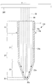
- FIG. 2 is a diagram showing a state in which the preform 100 is irradiated with the electron beam EB from the irradiation unit 200.
- FIG. 3 is a graph showing the relationship between the distance from the end 100a of the preform 100 and the absorbed dose.
- the preform 100 is transported and the electron beam is irradiated toward the inside of the preform 100.
- the electron beam is irradiated outside the preform 100 instead of inside the preform 100, it is sufficient if the absorbed dose of the electron beam is not sufficient at the bottom 30 of the preform 100 where the distance from the electron beam irradiation source is long. It may not be possible to perform a proper sterilization treatment. Further, if the acceleration energy of the electron beam is increased too much in order to obtain a sufficient absorbed dose of the electron beam at the bottom 30 of the preform 100, the absorbed dose of the electron beam is increased at a position where the distance from the irradiation source of the electron beam is short. It becomes excessive, and the preform 100 may be deformed or melted.
- an electron beam is used to sterilize the inner peripheral surface 10a, the inner peripheral surface 21a, the inner peripheral surface 22a, and the inner peripheral surface 30a, which are the inner peripheral surfaces of the preform 100.
- An irradiation unit 200 that irradiates the EB is used.
- the irradiation unit 200 is a device that irradiates the electron beam EB toward the spout portion 10 of the preform 100 along the axis X.
- the inner diameter D0 of the spout portion 10 and the inner diameter D1 of the straight line portion 21 connected to the spout portion 10 are constant at each position along the axis X. Therefore, when the electron beam EB is irradiated along the axis X, the absorbed dose of the electron beam EB in the spout portion 10 and the straight line portion 21 is relatively small.
- the inner diameter D2 of the inclined portion 22 connected to the straight portion 21 gradually decreases from the inner diameter D1 to the inner diameter D3 toward the bottom portion 30 with a constant gradient, so that the inner diameter D2 gradually decreases along the axis X.
- the absorbed dose of the electron beam EB in the inclined portion 22 becomes relatively large. Therefore, it is possible to prevent the absorbed dose of the electron beam EB on the spout portion 10 side of the preform 100 from becoming excessive while sufficiently securing the absorbed dose of the electron beam EB on the bottom 30 side of the preform 100.
- the inclined portion 22 is formed so that the inclination angle ⁇ of the inner peripheral surface 22a with respect to the axis X is 12 degrees or more and 22 degrees or less.
- the larger the inclination angle ⁇ the larger the absorbed dose per unit area on the bottom 30 side, but the region of the inclined portion 22 becomes narrower and the absorbed dose of the entire inclined portion decreases. Further, as the inclination angle ⁇ becomes smaller, the area of the inclined portion 22 becomes wider, but the absorbed dose per unit area on the bottom 30 side becomes smaller.
- the inventors formed the inclined portion 22 so that the inclination angle was 12 degrees or more and 22 degrees or less, so that the electrons on the bottom 30 side of the preform 100 were formed. It was found that it is possible to prevent the absorbed dose of the electron beam EB from becoming excessive on the spout portion 10 side of the preform 100 while sufficiently securing the absorbed dose of the wire EB.
- FIG. 3 is a graph showing the relationship between the distance from the end 100a of the preform 100 and the absorbed dose of the electron beam.
- the horizontal axis shown in FIG. 3 sets the position of the end portion 100a of the preform 100 to 0, and indicates the distance in the axis X direction from the end portion 100a of the inner peripheral surface of the preform 100.
- the maximum value of the distance in the axis X direction from the end portion 100a is L1.
- the vertical axis shown in FIG. 3 shows the ratio of the absorbed dose of the electron beam EB per unit time and unit area of the inner peripheral surface of the preform 100 when a predetermined reference value is set to 100%.
- the plot shown in FIG. 3 shows the percentage of absorbed dose obtained when the tilt angles ⁇ were set to 12 °, 17 °, 22 °, and 45 °.
- Examples in which the inclination angles ⁇ are 12 °, 17 °, and 22 ° are examples of the present embodiment included in the range of the above-mentioned equation (1).
- the example in which the inclination angle ⁇ is 45 ° is a comparative example of the present embodiment which is not included in the range of the above-mentioned equation (1).
- the absorbed dose is greatly reduced after the distance in the axis X direction from the end 100a of the inner peripheral surface of the preform 100 exceeds L1 / 2.
- the absorbed dose increases slightly just before the distance in the X direction of the axis approaches L1.
- the inclination angles ⁇ are 12 °, 17 °, and 22 °
- the distance from the end portion 100a of the inner peripheral surface of the preform 100 in the axis X direction exceeds L1 / 2, and then from the straight portion 21.
- the absorbed dose increases by switching to the inclined portion 22.
- the absorbed dose decreases as the distance in the axis X direction approaches L1 after the absorbed dose increases.
- the absorbed dose at each position from the position where the distance in the axis X direction is L1 / 2 to the position where it becomes L1 maintains a state higher than that of the comparative example in which the inclination angle ⁇ is 45 °.
- the inventors decided to set the inclination angle ⁇ within the range of the above-mentioned equation (1).
- the length L1 along the axis X from the end 100a on the spout portion 10 side of the preform 100 to the position where the inner peripheral surface 30a of the bottom 30 and the axis X intersect is the following formula. Set to satisfy (3). 0.5 ⁇ D1 ⁇ L1 ⁇ 3.0 ⁇ D1 (3) Further, it is more desirable that the length L1 is set so as to satisfy the following equation (4). 1.0 ⁇ D1 ⁇ L1 ⁇ 2.6 ⁇ D1 (4)
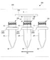
- FIG. 4 is a diagram showing a sterilizer 400 according to the present embodiment.
- the sterilizer 400 includes an irradiation unit 200 and a transport unit 300.
- the example shown in FIG. 4 shows a state in which the transport unit 300 transports three preforms 100, but the transport unit 300 can transport an arbitrary number of three or more preforms 100.
- the irradiation unit 200 is a device that irradiates the electron beam EB in the direction along the axis X toward the spout portion 10 of the preform 100.
- the irradiation unit 200 is arranged in a transport path 320 in which the transport unit 300 transports the preform 100.
- the irradiation unit 200 irradiates the electron beam EB from the outside of the preform 100 so as to reach the bottom portion 30 via the spout portion 10.
- the length L2 along the axis X from the position where the irradiation unit 200 of the present embodiment irradiates the electron beam EB to the spout portion 10 of the preform 100 is set to, for example, about 20 mm.
- the acceleration energy of the electron beam EB emitted from the irradiation unit 200 is set to, for example, 120 eV or more and 180 eV or less. This acceleration energy is preferably set so that the minimum absorbed dose of the electron beam EB on the inner circumference of the preform 100 is, for example, about 15 kGy.
- the transport unit 300 is a device that transports a plurality of preforms 100 along a transport direction TD that is orthogonal (intersects) with the axis X.
- the transport unit 300 includes a plurality of holding units 310 for holding the plurality of preforms 100.
- the transport unit 300 transports the preform 100 so as to pass below the irradiation unit 200 arranged in the transport path 320 by moving the holding portion 310 along the transport direction TD at a constant speed.
- the transport speed at which the transport unit 300 transports the preform 100 along the transport direction TD is set to, for example, 300 mm / sec or more and 500 mm / sec or less.
- the sterilizer 400 of the present embodiment executes the sterilization process of the preform 100 as follows. First, the preform 100 is installed so as to be held by the holding portion 310 of the conveying portion 300. Second, while the preform 100 is held by the holding unit 310, the preform 100 is conveyed by the conveying unit 300 along the conveying direction TD (conveying step). Thirdly, in a state where the preform 100 is transported along the transport direction TD by the transport unit 300, the electron beam EB is irradiated from the irradiation unit 200 to the inner peripheral surface of the preform 100 that passes below the irradiation unit 200. The electron beam reaches (irradiation step).
- the preform (100) described in each of the above-described embodiments is grasped as follows, for example.
- the preform according to the present disclosure is formed in a cylindrical shape along the axis (X) and has a spout portion (10) having one end opened, and is formed in a cylindrical shape along the axis (X) and described above.
- a body portion (20) connected to a spout portion (10) and a bottom portion (30) connected to the body portion and one end closed along the axis are provided, and the body portion is the mouth.
- the other end along the axis is connected to the bottom, and the second inner diameter (D2) in the radial direction gradually decreases from the straight portion to the bottom along the axis with a constant gradient.
- It has an inclined portion (22), and the inclined portion is formed so that the inclination angle of the inner peripheral surface with respect to the axis is 12 degrees or more and 22 degrees or less.
- the body portion connected to the spout portion is connected to the spout portion and the first inner diameter in the radial direction is constant at each position along the axis line and a straight line portion. It has an inclined portion which is connected to the portion and whose second inner diameter in the radial direction gradually decreases with a constant gradient from the straight portion to the bottom.
- the absorbed dose of the straight part when the electron beam is irradiated along the axis is relatively small.
- the second inner diameter of the inclined portion connected to the straight portion gradually decreases toward the bottom with a constant gradient, the absorbed dose of the inclined portion becomes relatively large when the electron beam is irradiated along the axis. .. Therefore, it is possible to prevent the absorbed dose of the electron beam on the spout portion side of the preform from becoming excessive while sufficiently securing the absorbed dose of the electron beam on the bottom side of the preform.
- the inclined portion is formed so that the inclination angle of the inner peripheral surface with respect to the axis is 12 degrees or more and 22 degrees or less.
- the larger the inclination angle the larger the absorbed dose per unit area on the bottom side, but the area of the inclined portion becomes narrower and the absorbed dose of the entire inclined portion decreases.
- the inclination angle becomes smaller, the area of the inclined portion becomes wider, but the absorbed dose per unit area on the bottom side becomes smaller.
- the inventors formed the inclined portion so that the inclination angle was 12 degrees or more and 22 degrees or less, thereby absorbing the electron beam on the bottom side of the preform. It was found that it is possible to prevent the absorbed dose of the electron beam on the spout side of the preform from becoming excessive while ensuring a sufficient dose.
- the length from the end of the spout portion (10) along the axis (X) to the bottom portion (30) is three times or less the first inner diameter (D1). There may be.
- the distance from the electron beam irradiation source to the bottom is sufficient with respect to the first inner diameter of the straight part. It will be short. Therefore, it is possible to prevent the distance from the electron beam irradiation source to the bottom portion to be longer than the first inner diameter, and the absorbed dose of the electron beam on the bottom side to be excessively reduced.
- the sterilizer (300) described in each of the above-described embodiments is grasped as follows, for example.
- a transport unit (300) that transports the preform along a transport direction (TD) that intersects the axis (X) and a transport unit (300) that transports the preform. It is provided with an irradiation unit (200) which is arranged in a transport path (320) and irradiates an electron beam in a direction along the axis toward the spout portion of the preform.
- the sterilizer According to the sterilizer according to the present disclosure, it is possible to prevent the absorbed dose of the electron beam on the spout side of the preform from becoming excessive while sufficiently securing the absorbed dose of the electron beam on the bottom side of the preform. can. Further, since it is not necessary to insert the irradiation source of the electron beam into the preform, the manufacturing cost of the sterilizer can be reduced.
- the sterilization method described in each of the above-described embodiments is grasped as follows, for example.
- the sterilization method according to the present disclosure sterilizes a preform, and the preform is formed in a cylindrical shape along an axis and a spout portion having an open end and a cylindrical shape along the axis.
- a body portion connected to the spout portion and a bottom portion connected to the body portion and one end closed along the axis line are provided, and the body portion is connected to the spout portion and is connected to the spout portion.
- the inclined portion is connected to the bottom portion and has an inclined portion in which the second inner diameter in the radial direction gradually decreases with a constant gradient from the spout portion to the bottom portion along the axis line.
- the inner peripheral surface is formed so that the inclination angle of the inner peripheral surface with respect to the axis is 12 degrees or more and 22 degrees or less, and the preform is conveyed along the conveying direction intersecting the axis, and the conveying step is performed.
- an irradiation step of irradiating an electron beam in a direction along the axis toward the spout portion of the preform is provided.
- the sterilization method it is possible to prevent the absorbed dose of the electron beam on the spout side of the preform from becoming excessive while sufficiently securing the absorbed dose of the electron beam on the bottom side of the preform. can. Further, since it is not necessary to insert the electron beam irradiation source into the preform, the preform can be sterilized by a relatively simple method.
- Mouth plug 20 Body 21 Straight line 21a Inner peripheral surface 22 Inclined part 22a Inner peripheral surface 30 Bottom 30a Inner peripheral surface 100 Preform 100a End part 200 Irradiation part 300 Transport part 320 Transport path 400 Sterilizer EB Electron beam TD Transport Direction X Axis ⁇ Tilt Angle
Landscapes
- Engineering & Computer Science (AREA)
- Manufacturing & Machinery (AREA)
- Mechanical Engineering (AREA)
- Physics & Mathematics (AREA)
- Health & Medical Sciences (AREA)
- Thermal Sciences (AREA)
- Life Sciences & Earth Sciences (AREA)
- Epidemiology (AREA)
- Geometry (AREA)
- Animal Behavior & Ethology (AREA)
- General Health & Medical Sciences (AREA)
- Public Health (AREA)
- Veterinary Medicine (AREA)
- Apparatus For Disinfection Or Sterilisation (AREA)
- Blow-Moulding Or Thermoforming Of Plastics Or The Like (AREA)
- Processing And Handling Of Plastics And Other Materials For Molding In General (AREA)
Priority Applications (1)
| Application Number | Priority Date | Filing Date | Title |
|---|---|---|---|
| EP21792721.9A EP4104991A4 (en) | 2020-04-22 | 2021-04-19 | PREFORM, STERILIZATION DEVICE AND STERILIZATION PROCESS |
Applications Claiming Priority (2)
| Application Number | Priority Date | Filing Date | Title |
|---|---|---|---|
| JP2020075913A JP7286585B2 (ja) | 2020-04-22 | 2020-04-22 | 殺菌システムおよび殺菌方法 |
| JP2020-075913 | 2020-04-22 |
Publications (1)
| Publication Number | Publication Date |
|---|---|
| WO2021215413A1 true WO2021215413A1 (ja) | 2021-10-28 |
Family
ID=78269430
Family Applications (1)
| Application Number | Title | Priority Date | Filing Date |
|---|---|---|---|
| PCT/JP2021/015934 Ceased WO2021215413A1 (ja) | 2020-04-22 | 2021-04-19 | プリフォーム、殺菌装置および殺菌方法 |
Country Status (3)
| Country | Link |
|---|---|
| EP (1) | EP4104991A4 (https=) |
| JP (1) | JP7286585B2 (https=) |
| WO (1) | WO2021215413A1 (https=) |
Citations (6)
| Publication number | Priority date | Publication date | Assignee | Title |
|---|---|---|---|---|
| JP2001225814A (ja) * | 2000-02-15 | 2001-08-21 | Toyo Seikan Kaisha Ltd | プリフォーム殺菌方法及びプリフォーム殺菌装置 |
| JP2005067002A (ja) * | 2003-08-22 | 2005-03-17 | Toyo Seikan Kaisha Ltd | プラスチックボトル容器用プリフォーム |
| JP2011000815A (ja) * | 2009-06-19 | 2011-01-06 | Aoki Technical Laboratory Inc | 延伸ブローボトルのプリフォーム |
| JP2013226709A (ja) * | 2012-04-25 | 2013-11-07 | Toppan Printing Co Ltd | 樹脂ボトル用プリフォーム |
| JP6091373B2 (ja) | 2013-08-05 | 2017-03-08 | 日立造船株式会社 | 電子線滅菌装置および無菌充填設備 |
| JP2017209136A (ja) * | 2016-05-23 | 2017-11-30 | 澁谷工業株式会社 | 電子線殺菌装置 |
Family Cites Families (4)
| Publication number | Priority date | Publication date | Assignee | Title |
|---|---|---|---|---|
| JPH0694158B2 (ja) * | 1990-10-26 | 1994-11-24 | 日精エー・エス・ビー機械株式会社 | 合成樹脂製の缶胴成形用プリフォーム及びそれを用いた合成樹脂製缶胴の製造方法 |
| JP3951660B2 (ja) | 2001-10-11 | 2007-08-01 | 日本ゼオン株式会社 | ブロー成形容器 |
| AU2003253840A1 (en) | 2002-07-11 | 2004-02-02 | Pall Corporation | Uv treated membranes |
| GB2524728B (en) * | 2014-03-28 | 2016-08-31 | Gr8 Eng Ltd | Injection molded preform and manufacture thereof |
-
2020
- 2020-04-22 JP JP2020075913A patent/JP7286585B2/ja active Active
-
2021
- 2021-04-19 EP EP21792721.9A patent/EP4104991A4/en not_active Withdrawn
- 2021-04-19 WO PCT/JP2021/015934 patent/WO2021215413A1/ja not_active Ceased
Patent Citations (6)
| Publication number | Priority date | Publication date | Assignee | Title |
|---|---|---|---|---|
| JP2001225814A (ja) * | 2000-02-15 | 2001-08-21 | Toyo Seikan Kaisha Ltd | プリフォーム殺菌方法及びプリフォーム殺菌装置 |
| JP2005067002A (ja) * | 2003-08-22 | 2005-03-17 | Toyo Seikan Kaisha Ltd | プラスチックボトル容器用プリフォーム |
| JP2011000815A (ja) * | 2009-06-19 | 2011-01-06 | Aoki Technical Laboratory Inc | 延伸ブローボトルのプリフォーム |
| JP2013226709A (ja) * | 2012-04-25 | 2013-11-07 | Toppan Printing Co Ltd | 樹脂ボトル用プリフォーム |
| JP6091373B2 (ja) | 2013-08-05 | 2017-03-08 | 日立造船株式会社 | 電子線滅菌装置および無菌充填設備 |
| JP2017209136A (ja) * | 2016-05-23 | 2017-11-30 | 澁谷工業株式会社 | 電子線殺菌装置 |
Non-Patent Citations (1)
| Title |
|---|
| See also references of EP4104991A4 |
Also Published As
| Publication number | Publication date |
|---|---|
| EP4104991A1 (en) | 2022-12-21 |
| EP4104991A4 (en) | 2023-08-30 |
| JP7286585B2 (ja) | 2023-06-05 |
| JP2021171964A (ja) | 2021-11-01 |
Similar Documents
| Publication | Publication Date | Title |
|---|---|---|
| US9155807B2 (en) | Method and apparatus for the sterilization of containers | |
| JP6282667B2 (ja) | 電子線により包装容器を無菌化するための装置および方法 | |
| US8800248B2 (en) | System for aseptically filling a container with a beverage or food | |
| CN104415383B (zh) | 以同时进行的内部和外部杀菌对塑料型坯进行杀菌的系统 | |
| US20180015191A1 (en) | Device and method for sterilizing thermoplastic containers using a pulsed electron beam and a mobile reflector | |
| JP2010523374A (ja) | 容器製造装置および容器製造方法 | |
| CN108136652A (zh) | 用于减少容器产品的微生物负载的方法 | |
| EP3099339B1 (en) | Device and method for sterilization of packaging containers | |
| WO2021215413A1 (ja) | プリフォーム、殺菌装置および殺菌方法 | |
| JP6614440B2 (ja) | ブロー成形方法 | |
| JP2017521278A (ja) | 内部真空力を収容するために移動可能なベースを有する、ダブルブロー法から生じた耐熱性二軸延伸ブロー成形プラスチック容器 | |
| EP2961437A1 (fr) | Procede de decontamination par irradiation de l'interieur d'une preforme | |
| JP6533422B2 (ja) | 予備成形体の加熱方法、底付き筒状容器の製造方法および予備成形体 | |
| KR102825832B1 (ko) | 열가소성 재질 용기의 제조 장치 및 방법 | |
| JP6543260B2 (ja) | 包装容器を殺菌するためのデバイスおよび方法 | |
| JP2005280329A (ja) | プラスチック容器およびその製造方法 | |
| JP6986236B2 (ja) | プラスチックボトルおよびプリフォーム | |
| CN101466602B (zh) | 消毒包装的方法 | |
| JP2022187277A (ja) | プリフォーム、及び合成樹脂製容器の製造方法 | |
| JP2021171964A5 (https=) | ||
| US10053252B2 (en) | Method and device for sterilizing packaging material | |
| WO2017057728A1 (ja) | ブロー成形方法 | |
| JP2019209983A (ja) | 押出ブロー成形容器 | |
| JPH1045115A (ja) | プラスチック製薬液容器の製造方法 |
Legal Events
| Date | Code | Title | Description |
|---|---|---|---|
| 121 | Ep: the epo has been informed by wipo that ep was designated in this application |
Ref document number: 21792721 Country of ref document: EP Kind code of ref document: A1 |
|
| ENP | Entry into the national phase |
Ref document number: 2021792721 Country of ref document: EP Effective date: 20220913 |
|
| NENP | Non-entry into the national phase |
Ref country code: DE |
|
| WWW | Wipo information: withdrawn in national office |
Ref document number: 2021792721 Country of ref document: EP |