WO2021215214A1 - 作業機 - Google Patents
作業機 Download PDFInfo
- Publication number
- WO2021215214A1 WO2021215214A1 PCT/JP2021/013895 JP2021013895W WO2021215214A1 WO 2021215214 A1 WO2021215214 A1 WO 2021215214A1 JP 2021013895 W JP2021013895 W JP 2021013895W WO 2021215214 A1 WO2021215214 A1 WO 2021215214A1
- Authority
- WO
- WIPO (PCT)
- Prior art keywords
- housing
- lever
- motor
- switch
- stopper
- Prior art date
- Legal status (The legal status is an assumption and is not a legal conclusion. Google has not performed a legal analysis and makes no representation as to the accuracy of the status listed.)
- Ceased
Links
Images


Classifications
-
- B—PERFORMING OPERATIONS; TRANSPORTING
- B24—GRINDING; POLISHING
- B24B—MACHINES, DEVICES, OR PROCESSES FOR GRINDING OR POLISHING; DRESSING OR CONDITIONING OF ABRADING SURFACES; FEEDING OF GRINDING, POLISHING, OR LAPPING AGENTS
- B24B23/00—Portable grinding machines, e.g. hand-guided; Accessories therefor
- B24B23/02—Portable grinding machines, e.g. hand-guided; Accessories therefor with rotating grinding tools; Accessories therefor
- B24B23/028—Angle tools
-
- B—PERFORMING OPERATIONS; TRANSPORTING
- B25—HAND TOOLS; PORTABLE POWER-DRIVEN TOOLS; MANIPULATORS
- B25F—COMBINATION OR MULTI-PURPOSE TOOLS NOT OTHERWISE PROVIDED FOR; DETAILS OR COMPONENTS OF PORTABLE POWER-DRIVEN TOOLS NOT PARTICULARLY RELATED TO THE OPERATIONS PERFORMED AND NOT OTHERWISE PROVIDED FOR
- B25F5/00—Details or components of portable power-driven tools not particularly related to the operations performed and not otherwise provided for
- B25F5/02—Construction of casings, bodies or handles
Definitions
- the present invention relates to a working machine.
- the housing constituting the outer shell of the electric grinding machine includes a gear cover, a motor housing (first housing), and a tail cover (second housing). These housings are arranged side by side in this order in the front-rear direction. Further, the front end portion of the switch lever (lever) configured as the operation portion of the electric grinder is rotatably connected to the motor housing. On the other hand, the rear end portion of the switch lever is engaged with the tail cover to limit the rotation range of the switch lever. Then, when the switch lever is operated, the switch lever rotates about the front end portion, and the switch in the tail cover is pressed by the switch lever. As a result, the motor in the motor housing is driven to operate the electric grinder.
- the tail cover is divided into two parts on the left and right. Therefore, when assembling the switch lever to the housing, the tip of the switch lever is connected to the motor housing, the rear end of the switch lever is engaged with the divided tail cover, and the two divided tail covers are engaged with each other. It was necessary to assemble and assemble the assembled tail cover to the motor housing. As a result, assembling each member becomes complicated in the electric grinding machine, and there is room for improvement in terms of productivity improvement regarding assembling property. Another issue is that when the switch is operated by the operation of the switch lever, for example, the internal configuration (electrical components) such as wiring may interfere with the operation of the switch lever, which may interfere with the operation of the switch. there were.
- An object of the present invention is to provide a working machine capable of improving assembling property in consideration of the above facts. Yet another object is to provide a working machine capable of maintaining good operation of the switch lever.
- One or more embodiments of the present invention rotate into a first housing that houses a motor, a second housing that is connected to the first housing and houses a switch that turns the motor on and off, and the second housing.
- the second housing is integrally formed with a lever that turns on the switch by being rotated from an initial position to an operation position, and one of the second housing and the lever, while having a rotation shaft that is possibly connected.
- a working machine including a stopper portion that regulates the rotation range of the lever by engaging with the other of the lever, and the lever and the second housing are each a single member. be.
- the stopper portion extends to the other side of the second housing and the lever, and an engaging portion is formed at the tip end portion of the stopper portion.
- a hole into which the stopper is inserted is formed in the other of the second housing and the lever, and the hole is engaged with the engaging portion in the extending direction of the stopper. It is a working machine in which a joint is formed.
- One or more embodiments of the present invention is a working machine in which the stopper portion is provided in the second housing and the hole portion is formed in the lever.
- the lever extends in the axial direction of the motor, and the rotation axis has an axial direction orthogonal to the extending direction of the lever.
- a working machine in which a pair of stoppers arranged in the orthogonal direction are provided in the second housing, and a pair of holes arranged in the orthogonal direction are formed in the lever.
- the lever is rotatably provided with an off-lock member, and at the locked position of the off-lock member, the off-lock member hits the second housing.
- the rotation of the lever at the initial position is restricted, and the off-lock member is rotated to the unlocked position, so that the lever is allowed to rotate from the initial position to the operating position.
- it is a working machine in which the hole portion and the off-lock member are arranged side by side in the orthogonal direction.
- the rotating shaft is fitted into a support hole of the second housing by snap-fit fitting and rotatably connected to the second housing.
- a working machine in which an inclined portion for promoting the snap-fit fitting is formed on at least one of the moving shaft and the second housing.
- One or more embodiments of the present invention have a spring that urges the lever at the operating position to the initial position, and the lever has a spring locking portion that holds the spring.
- a switch operating portion projecting toward the second housing is provided for operating the switch, and at least a part of the spring locking portion and the switch operating portion are the same in the extending direction of the lever. It is a working machine in position.
- the switch is held in the first housing, and the second housing in which the lever is held is connected to the first housing in which the switch is held.
- This is a working machine in which the first housing and the second housing are assembled so that the switch can be operated by the lever.
- One or more embodiments of the present invention include a first housing that houses a motor, a switch that is supported by the first housing and turns the motor on and off, and a rotation that is rotatably connected to the second housing. It has a moving shaft and is integrally formed with a lever that turns on the switch by being rotated from an initial position to an operating position, and one of the second housing and the lever, and is formed on the other of the second housing and the lever.
- the second housing is provided with a stopper portion that regulates the rotation range of the lever by engaging with the lever, and the second housing can be assembled to the first housing in a state of supporting the switch. It is a work machine configured in.
- the assembling property can be improved.
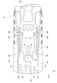
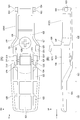
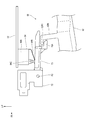
- FIG. 2 It is a side view seen from the left side which shows the disc grinder which concerns on this embodiment. It is a bottom view seen from the lower side which shows the rear part of the disc grinder shown in FIG. It is a side sectional view seen from the left side which shows the inside of the disc grinder shown in FIG. It is the bottom view which looked at the rear housing shown in FIG. 2 from the lower side. It is a layout diagram seen from the lower side schematically showing the arrangement state of the motor side lead wire and the substrate side lead wire for connecting the motor and the control board shown in FIG. (A) is a cross-sectional view (cross-sectional view taken along the line 6A-6A of FIG. 2) showing a state in which the stopper portion of the rear housing shown in FIG.
- B) is a perspective view of the inserted state of the stopper portion shown in (A) into the stopper insertion portion as viewed from diagonally upper left. It is a cross-sectional view (7-7 line cross-sectional view of FIG. 2) seen from the front side which shows the state which the rotation shaft of the paddle lever shown in FIG. 2 is inserted into the support hole of a rear housing.
- (A) is a plan view of the paddle lever shown in FIG. 2 as viewed from above
- (B) is a side view of the paddle lever of (A) as viewed from the left side.
- FIG. 8 is a cross-sectional view taken from diagonally upper right side showing an intermediate portion in the longitudinal direction of the huddle lever shown in FIG. It is a figure which shows the process of attaching a huddle lever. It is a side view seen from the left side which shows the operation mechanism part of the disc grinder shown in FIG.
- a disc grinder 10 (hereinafter, simply referred to as a grinder 10) as a working machine according to the present embodiment will be described with reference to the drawings.
- the arrows UP, FR, and RH appropriately shown in the drawings indicate the upper side, the front side, and the right side of the grinder 10, respectively.
- the grinder 10 is indicated in the vertical direction, the front-back direction, and the left-right direction unless otherwise specified. Further, the left-right direction corresponds to the orthogonal direction of the present invention.
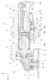
- the grinder 10 is configured as a tool for performing cutting, polishing, or the like on a work material. As shown in FIGS. 1 to 3, the grinder 10 includes a housing 20, a motor 30, a transmission mechanism 50, an operation mechanism unit 60, and a control unit 80. Hereinafter, each configuration of the grinder 10 will be described.
- the housing 20 constitutes the outer shell of the grinder 10 and is formed as a hollow substantially cylindrical shape extending in the front-rear direction as a whole.
- the housing 20 includes a motor housing 22 as a first housing forming an intermediate portion in the front-rear direction of the housing 20, a gear housing 24 forming a front end portion of the housing 20, and a second housing forming a rear end portion of the housing 20.
- the rear housing 26 and the rear housing 26 of the above are included. Further, inside the rear housing 26, a board holder 28 for holding the control board 82 of the control unit 80, which will be described later, is provided.
- the motor housing 22 is formed in a substantially cylindrical shape with the front-rear direction as the axial direction.
- the inside of the motor housing 22 is configured as a motor accommodating portion 22A for accommodating the motor 30 described later.
- a diameter-expanded portion 22B extending outward in the radial direction is formed at the front end portion of the motor housing 22, and the diameter-expanded portion 22B is formed in a substantially rectangular shape when viewed from the front.
- a fan 42 which will be described later, is housed in the enlarged diameter portion 22B.
- a bearing accommodating portion 22C for accommodating the second motor bearing 36, which will be described later, is formed inside the rear end portion of the motor housing 22.
- the bearing accommodating portion 22C is formed in a substantially cylindrical shape with the front-rear direction as the axial direction, and is arranged coaxially with the motor housing 22.
- the bearing accommodating portion 22C is connected to the side wall portion of the motor housing 22 by a connecting rib (not shown) provided around the bearing accommodating portion 22C.
- a pair of upper and lower holder fixing portions 22D for fixing the substrate holder 28, which will be described later, are formed on the radial outer side of the bearing accommodating portion 22C.
- the holder fixing portion 22D is formed in a substantially cylindrical shape with the front-rear direction as the axial direction, and is connected to the bearing accommodating portion 22C and the motor housing 22. Further, a female screw is formed on the inner peripheral portion of the holder fixing portion 22D.
- the rear end portion of the motor housing 22 is inclined forward as it goes downward in a side view.
- a step portion 22E is formed on the outer peripheral portion of the rear end portion of the motor housing 22, and the step portion 22E is lowered one step inward in the radial direction from the outer peripheral portion of the motor housing 22. Further, the step portion 22E is formed over the entire circumference of the rear end portion of the motor housing 22.
- the gear housing 24 has a base portion 24A constituting the rear end portion of the gear housing 24, and the base portion 24A is formed in the motor housing 22 in a substantially rectangular tubular shape corresponding to the enlarged diameter portion 22B. Has been done. Then, the enlarged diameter portion 22B is inserted into the base portion 24A, and the outer peripheral portion of the base portion 24A is fixed to the enlarged diameter portion 22B at a position (not shown). Further, the gear housing 24 is formed with an overhanging portion 24B extending forward from the base portion 24A, and the overhanging portion 24B is formed in a substantially triangular shape in a side view and is opened downward. ing.
- the substrate holder 28 is formed in a substantially long box shape that is open downward and extends in the front-rear direction. ing.
- a pair of upper and lower fixed portions 28A are formed on the front wall of the board holder 28 at positions corresponding to the holder fixing portions 22D of the motor housing 22, and the fixed portions 28A are substantially axially oriented in the front-rear direction. It is formed in a cylindrical shape. Then, the fixing screw SC1 is inserted into the fixed portion 28A from the rear side and screwed into the female screw of the holder fixing portion 22D, so that the substrate holder 28 is fixed to the motor housing 22.
- a fixing boss 28B (see FIG. 5) for fixing the rear housing 26, which will be described later, to the motor housing 22 is formed at the rear end of the board holder 28.
- the fixed boss 28B is formed in a substantially cylindrical shape with the front-rear direction as the axial direction, and a female screw is formed on the inner peripheral portion of the fixed boss 28B.
- a fixing screw SC2 can be screwed into the fixing boss 28B.
- the rear housing 26 can be fixed to the motor housing 22 by fixing the rear housing 26 to the board holder 28 fixed to the motor housing 22 using the fixing screws SC2.
- the rear housing 26 is made of resin and is formed in a substantially bottomed cylindrical shape that is open to the front side.
- the inside of the rear housing 26 is configured as a substrate accommodating portion 26A.
- a fixing hole (not shown) is formed through the rear wall of the rear housing 26 at a position corresponding to the fixing boss 28B of the substrate holder 28.
- the fixing screw SC2 is inserted into the fixing hole from the rear side and screwed into the fixing boss 28B to fix the rear housing 26 to the board holder 28.
- the front end portion of the rear housing 26 is extrapolated to the stepped portion 22E of the rear end portion of the motor housing 22. That is, the board holder 28 fixes the rear housing 26 and also functions as a member for connecting the rear housing 26 to the motor housing 22.
- the front end surface of the rear housing 26 is inclined forward as it goes downward in a side view.
- a protruding portion 26B protruding downward is formed at the rear end portion of the rear housing 26.
- the protrusion 26B is formed in a substantially trapezoidal block shape when viewed from the side.
- a surrounding wall 26C protruding downward is formed on the front side of the protruding portion 26B, and the surrounding wall 26C is opened to the front side when viewed from the lower side. It is formed in a substantially U-shape.
- the space surrounded by the surrounding wall 26C is configured as a lever accommodating portion 26D for accommodating the paddle lever 62 described later, and the lever accommodating portion 26D is open to the lower side and the front side.
- bent portions 26E are formed at intermediate portions in the front-rear direction of the left and right side walls of the surrounding wall 26C.
- the bent portion 26E is bent in a substantially crank shape when viewed from below, and the width dimension (left-right direction dimension) of the front portion of the lever accommodating portion 26D is larger than the width dimension of the rear portion of the lever accommodating portion 26D. Is set to.
- the paddle lever 62 which will be described later, is located above the straight line connecting the lower end of the protrusion 26B and the rear end of the grindstone 53, so that the paddle lever 62 comes into contact with the ground or the like. It can be suppressed.
- a pair of left and right stopper portions 26F are formed at the front end portion of the lever accommodating portion 26D on the lower outer peripheral portion of the rear housing 26.
- the pair of stopper portions 26F are arranged at positions symmetrical with respect to the central portion in the left-right direction of the rear housing 26.
- the stopper portion 26F is formed in a substantially long plate shape extending in the vertical direction with the horizontal direction being the plate thickness direction, and extends downward from the rear housing 26.
- Reinforcing ribs 26F1 are formed at the rear end of the stopper portion 26F, and the reinforcing ribs 26F1 project outward from the stopper portion 26F in the left-right direction and extend in the up-down direction. That is, in the stopper portion 26F on the right side, the reinforcing rib 26F1 protrudes to the right from the stopper portion 26F, and in the stopper portion 26F on the left side, the reinforcing rib 26F1 protrudes to the left from the stopper portion 26F. Further, an engaging portion 26F2 is formed at the tip end portion (lower end portion) of the stopper portion 26F. The engaging portion 26F2 projects outward from the stopper portion 26F in the left-right direction, and the rear end portion of the engaging portion 26F2 is connected to the reinforcing rib 26F1.
- a contact portion 26G configured to be in contact with an off-lock member 66, which will be described later, is formed between the pair of stopper portions 26F on the lower outer peripheral portion of the rear housing 26. There is.
- the contact portion 26G is formed in a substantially U shape that is open to the front side when viewed from the lower side, and protrudes downward from the rear housing 26.
- an insertion hole 26H is formed through the outer peripheral portion of the rear housing 26 on the rear side of the stopper portion 26F on the left side. That is, the insertion hole 26H is arranged closer to the left side with respect to the center portion in the left-right direction of the rear housing 26.
- the insertion hole 26H is formed in a substantially rectangular shape with the front-rear direction as the longitudinal direction when viewed from below, and is arranged adjacent to the inside of the side wall of the surrounding wall 26C in the left-right direction.
- a pair of left and right spring mounting portions 26J for mounting the lever urging spring 64 are formed on the rear side of the contact portion 26G.
- the spring mounting portion 26J is formed in a substantially L-shape that is open to the front side and inward in the left-right direction when viewed from the lower side, and protrudes downward from the rear housing 26. Further, on the outer peripheral portion of the rear housing 26, a spring locking portion 26K is formed between the pair of spring mounting portions 26J, and the spring locking portion 26K is a substantially cross (plus sign) when viewed from below. It is formed in a shape and protrudes downward from the rear housing 26.
- a pair of left and right support portions 26L that rotatably support the paddle lever 62, which will be described later, are formed at the rear end portion of the side wall of the surrounding wall 26C. ..
- the pair of left and right support portions 26L are configured to be indivisible.
- the support portion 26L projects inward in the left-right direction from the inner peripheral surface of the surrounding wall 26C.
- a circular support hole 26M is formed through the support portion 26L in the left-right direction.
- a housing-side inclined surface 26N as an inclined portion is formed below the support hole 26M.
- the housing-side inclined surface 26N is inclined outward in the left-right direction as it goes downward when viewed from the front-rear direction.
- a regulation rib 26P as a regulation portion is formed on the lower inner peripheral surface of the rear housing 26.
- the regulation rib 26P has a plate thickness direction in the left-right direction and extends in the front-rear direction.
- the regulation rib 26P is arranged adjacent to the right side of the insertion hole 26H and projects upward from the inner peripheral surface of the rear housing 26.
- the front end portion of the regulation rib 26P is located on the right side of the intermediate portion in the front-rear direction of the insertion hole 26H, and the rear end portion of the regulation rib 26P is connected to the rear wall of the rear housing 26.
- the lower end portion of the substrate accommodating portion 26A is partitioned in the left-right direction by the regulation rib 26P.
- the region on the right side with respect to the regulation rib 26P at the lower end portion of the substrate accommodating portion 26A is configured as the wiring accommodating region 26A1 (see FIG. 6A), and the regulation rib at the lower end portion of the substrate accommodating portion 26A.
- the region on the left side of 26P is configured as the lever operating region 26A2 (see FIG. 6A).
- a plurality of intake ports 26R are formed through the left and right side portions of the rear housing 26.
- the intake ports 26R have a plurality of intake ports 26R arranged substantially in the vertical direction as one set, and five sets of intake ports 26R are arranged side by side in the front-rear direction.
- the motor 30 is configured as a three-phase brushless motor and is housed in the motor housing portion 22A of the motor housing 22.
- the motor 30 includes a rotor 32 and a stator 33, and a rotating shaft 31 is attached to the rotor 32.
- the rotation shaft 31 is arranged with the front-rear direction as the axial direction.
- the front end of the rotating shaft 31 is rotatably supported by the first motor bearing 35 fixed to the gear housing 24, and the rear end of the rotating shaft 31 is fixed to the bearing accommodating portion 22C of the motor housing 22. It is rotatably supported by a second motor bearing 36.
- the rotor 32 is arranged on the outer side in the radial direction of the rotating shaft 31, and is configured to be integrally rotatable with the rotating shaft 31.
- the stator 33 is formed in a substantially cylindrical shape with the front-rear direction as the axial direction, and is supported by the motor housing 22 on the radial outer side of the rotor 32.
- the stator 33 has a stator holder, and a stator coil corresponding to the U phase, V phase, and W phase of the motor 30 is wound around the stator holder.
- the lead wires 38A, 38B, and 38C on the motor side as electrical components and wiring, respectively (see the lead wires painted in gray in FIG. 5). ) Is connected.
- the motor-side lead wires 38A, 38B, and 38C are arranged below the bearing accommodating portion 22C of the motor housing 22, and are arranged in the wiring accommodating area 26A1 of the rear housing 26. That is, the motor-side lead wires 38A, 38B, and 38C extend in the front-rear direction in the wiring accommodation area 26A1 of the rear housing 26. Further, the other ends of the motor-side lead wires 38A, 38B, and 38C are connected to the electrical components and the substrate-side lead wires 40A, 40B, 40C as wirings (see the lead wires painted in black in FIG. 5). ), And the board-side lead wires 40A, 40B, and 40C are connected to the control board 82 of the control unit 80, which will be described later.
- the motor 30 is configured to be driven by the control unit 80.
- the substrate-side lead wires 40A, 40B, 40C are arranged in the wiring accommodation area 26A1 in the same manner as the motor-side lead wires 38A, 38B, 38C.
- a fan 42 is integrally rotatable on the rear side of the first motor bearing 35 on the front end side portion of the rotating shaft 31.
- the fan 42 is configured as an axial fan.
- the fan 42 is configured to generate an air flow from the rear side to the front side.
- air flows into the housing 20 from the intake port 26R of the rear housing 26, and the air is discharged from the exhaust port (not shown) formed in the overhanging portion 24B of the gear housing 24. Therefore, the control unit 80 and the motor 30, which will be described later, are cooled by the air flow generated by the fan 42.
- the front end portion of the rotating shaft 31 is housed in the overhanging portion 24B of the gear housing 24, and the pinion gear 44 is fixed to the front end portion of the rotating shaft 31.
- the gear teeth of the pinion gear 44 are inclined inward in the radial direction of the rotating shaft toward the front side.
- the transmission mechanism 50 has an output shaft 51 whose axial direction is the vertical direction, and the output shaft 51 is housed in the overhanging portion 24B of the gear housing 24.
- the vertical intermediate portion of the output shaft 51 is rotatably supported by a bearing 52 fixed to the gear housing 24.
- the lower end of the output shaft 51 is configured as a tool mounting portion 51A, and a male screw is formed on the outer peripheral portion of the tool mounting portion 51A.
- a disk-shaped grindstone 53 as a tool is attached to the tool attachment portion 51A.
- the grindstone 53 is mounted on the tool mounting portion 51A by externally inserting the mounting hole 53A of the grindstone 53 into the tool mounting portion 51A and screwing the nut N into the tool mounting portion 51A.
- the outer peripheral portion of the grindstone 53 is partially covered with the foil guard 55.
- the wheel guard 55 is configured so that a portion having a large number of grindstones 53 can be arbitrarily changed, and in the states of FIGS. 1 and 3, the wheel guard 55 is in a position of covering the rear portion of the grindstone 53.
- a bevel gear 54 is fixed to the upper end of the output shaft 51, and the bevel gear 54 is meshed with the pinion gear 44. As a result, when the motor 30 is driven, the rotation of the motor 30 is transmitted to the output shaft 51, and the grindstone 53 rotates around the axis of the output shaft 51.
- the operation mechanism unit 60 includes a paddle lever 62 as a lever, an off-lock member 66, and an interlocking lever 70. It is configured.
- the paddle lever 62 is made of resin and is formed in a substantially rectangular concave shape that is open upward and extends in the front-rear direction.
- the paddle lever 62 includes a bottom wall 62A and a peripheral wall 62B protruding upward on the outer peripheral portion of the bottom wall 62A.
- a lever step portion 62C is formed in the middle portion in the front-rear direction of the bottom wall 62A, and the lever step portion 62C is substantially bent on the crank in a side view and is inclined upward as it goes to the front side. ..
- the portion of the paddle lever 62 on the front side of the lever step portion 62C is configured as the lever grip portion 62D, and the portion of the paddle lever 62 on the rear side of the lever step portion 62C is configured as the lever body portion 62E (lever center portion).
- the lever grip portion 62D is configured as a portion to be gripped by the user, and the wall thickness of the lever grip portion 62D is set to be thinner than the wall thickness of the lever main body portion 62E.
- a pair of left and right bent portions 62F are formed on the rear side of the lever step portion 62C at the intermediate portion in the front-rear direction of the peripheral wall 62B.
- the bent portion 62F is bent in a substantially crank shape when viewed from below, and the width dimension (dimension in the left-right direction) of the rear end portion of the lever body portion 62E is set to be smaller than the width dimension of the other portion. Has been done.
- a pair of left and right rotating shafts 62G are formed at the rear end of the side wall of the peripheral wall 62B.
- the rotating shaft 62G is formed in a substantially columnar shape with the left-right direction as the axial direction, and projects outward from the peripheral wall 62B in the left-right direction (outside in the width direction of the paddle lever 62).
- the rear end portion of the paddle lever 62 is accommodated in the lever accommodating portion 26D of the rear housing 26, and the rotating shaft 62G is inserted into the support hole 26M of the rear housing 26 from the inside in the left-right direction to enter the support hole 26M. It is rotatably supported.
- the paddle lever 62 is rotatably connected to the rear housing 26.
- the paddle lever 62 is shown at the initial position (the position shown by the solid line in FIG. 1) and the operation position rotated clockwise from the initial position when viewed from the left side (shown by the alternate long and short dash line in FIG. 1). It is configured to rotate between (position) and. Then, in the initial position, the paddle lever 62 is tilted downward toward the front side, and in the operating position, the paddle lever 62 is set to be substantially horizontal. Further, in the connected state of the paddle lever 62 to the rear housing 26, the lever grip portion 62D of the paddle lever 62 extends forward from the lever accommodating portion 26D and is arranged below the motor housing 22. This allows the operator to operate the paddle lever 62 while grasping the motor housing 22 that does not have the intake port 26R.
- a shaft-side inclined surface 62H as an inclined portion is formed on the upper portion of the tip surface of the rotating shaft 62G.
- the axial side inclined surface 62H is inclined inward in the left-right direction as it goes upward when viewed from the front-rear direction.
- the rotation shaft 62G is arranged below the housing-side inclined surface 26N of the rear housing 26 (the paddle lever 62 shown by the chain double-dashed line in FIG. 7).
- the shaft-side inclined surface 62H slides on the housing-side inclined surface 26N, and the peripheral wall 62B of the paddle lever 62 and the surrounding wall 26C of the rear housing 26 are bent and deformed.
- the rotating shaft 62G is configured to be fitted into the support hole 26M. That is, by so-called snap-fit fitting, the rotating shaft 62G is rotatably fitted into the support hole 26M.
- the housing-side inclined surface 26N and the shaft-side inclined surface 62H are configured as functional portions for promoting snap-fit fitting between the rotating shaft 62G and the support hole 26M.
- a pair of left and right stopper insertion portions 62J are formed on the bottom wall 62A of the paddle lever 62 on the rear side of the lever step portion 62C.
- the stopper insertion portion 62J is arranged at a position corresponding to the stopper portion 26F of the rear housing 26 described above.
- the stopper insertion portion 62J is formed in a substantially rectangular tubular shape with the vertical direction in the axial direction, and the outer wall portion in the left-right direction of the stopper insertion portion 62J is formed by a peripheral wall 62B.
- the inside of the stopper insertion portion 62J is configured as an insertion hole 62J1 as a hole portion, and the insertion hole 62J1 penetrates in the vertical direction.
- the upper opening of the stopper insertion portion 62J is provided with an engaged portion 62J2 at a corner portion on the front side and on the outer side in the left-right direction.
- the engaged portion 62J2 is formed in a substantially rectangular plate shape with the vertical direction being the plate thickness direction and the front-rear direction and the longitudinal direction.
- the upper opening of the stopper insertion portion 62J is formed in a substantially L shape.
- the front side is partially closed by the engaged portion 62J2 so as to be narrow in the left-right direction and wide on the rear side.
- the stopper portion 26F of the rear housing 26 is inserted into the insertion hole 62J1 of the stopper insertion portion 62J from the upper opening of the stopper insertion portion 62J. Further, in the state where the stopper portion 26F is inserted into the stopper insertion portion 62J, the stopper portion 26F is arranged inside the engaged portion 62J2 in the left-right direction, and the engaging portion 26F2 of the stopper portion 26F is engaged. It is arranged adjacent to the lower side of 62J2. As a result, the engaging portion 26F2 and the engaged portion 62J2 are engaged (contacted) in the vertical direction, and the downward rotation of the paddle lever 62 at the initial position is restricted.
- the state in which the engaging portion 26F2 and the engaged portion 62J2 are engaged is the initial position of the paddle lever 62. Further, the stopper portion 26F is sandwiched in the left-right direction by the inner peripheral surface of the stopper insertion portion 62J (specifically, the inner peripheral surface inside in the left-right direction) and the engaged portion 62J2. Therefore, the stopper insertion portion 62J and the engaged portion 62J2 are configured to limit the displacement of the stopper portion 26F in the left-right direction. That is, the pair of left and right stoppers 26F suppresses the paddle lever 62 from swinging, deforming, or bending in the left-right direction.
- a spring seat portion 62K is formed at the rear portion of the bottom wall 62A of the paddle lever 62.
- the spring seat portion 62K is arranged on the rear side of the stopper insertion portion 62J and at the center portion in the left-right direction of the paddle lever 62.
- the spring seat portion 62K is formed in a substantially columnar shape with the vertical direction as the axial direction, and projects upward from the bottom wall 62A.
- a lever urging spring 64 (see FIG. 3) as a spring is mounted on the spring seat portion 62K.
- the lever urging spring 64 is configured as a compression coil spring, and the lower end of the lever urging spring 64 is locked to the spring seat portion 62K.
- the upper end portion of the lever urging spring 64 is arranged between the pair of spring mounting portions 26J in the rear housing 26 and is locked to the rear housing 26.
- the paddle lever 62 is urged downward and held in the initial position by the urging force of the lever urging spring 64.
- a spring locking portion 62L is formed on the upper surface of the spring seat portion 62K, and the spring locking portion 62L is formed in a substantially cross (plus sign) shape when viewed from above.
- the spring locking portion 26K of the rear housing 26 and the spring locking portion 62L of the paddle lever 62 are arranged inside the lever urging spring 64 to limit the movement of the lever urging spring. ..
- FIG. 10 is a diagram showing a process of attaching the paddle lever 62 to the rear housing 26.
- the engaging portion 26F2 is opened to the upper side of the stopper insertion portion 62J as shown in FIG. 10 (A). Insert from the part.
- the upper opening of the stopper insertion portion 62J is partially closed by the engaged portion 62J2, and the engaging portion 26F2 cannot pass through this closed region, so that the engaging portion 26F2 is engaged.
- the engaging portion 26F2 is positioned under the engaged portion 62J2.
- the reinforcing rib 26F1 is located behind the engaged portion 62J2 to prevent the paddle lever 62 from moving backward more than necessary. .. That is, the reinforcing rib 26F1 not only improves the durability of the stopper portion 26F itself, but also functions as an auxiliary member when assembling the paddle lever 62 to the rear housing 26.
- the rotation shaft 62G and the support hole 26M are in the same position in the front-rear direction, and are in a positional relationship in which they can be engaged with each other.
- the rotating shaft 62G is engaged with the support hole 26M by the snap-fit fitting described above (the state shown in FIG. 10C). ).
- the paddle lever 62 is separated from the rear housing 26 by the engagement between the engaged portion 62J2 and the engaging portion 26F2 (the direction in which the paddle lever 62 is separated from the rear housing 26 ().
- an arrangement hole 62M for arranging the off-lock member 66 described later is formed through the bottom wall 62A of the paddle lever 62 between the pair of stopper insertion portions 62J.
- the arrangement hole 62M is formed in a substantially rectangular shape in a plan view.
- a pair of left and right bearing portions 62N are formed on the bottom wall 62A of the paddle lever 62, and the bearing portions 62N are arranged between the arrangement hole 62M and the stopper insertion portion 62J, and from the bottom wall 62A. It protrudes upward.
- a bearing groove 62P is formed in the bearing portion 62N, and the bearing groove 62P is open on the upper side and inward in the left-right direction. Further, support pins P1 (see FIGS. 6A and 6B) having an axial direction in the left-right direction are bridged to the pair of bearing portions 62N, and both ends in the longitudinal direction of the support pins P1 are bearings. It is fitted in the lower end of the groove 62P.
- a switch operating portion 62R for operating a switch 84 which will be described later, is provided on the peripheral wall 62B on the left side of the paddle lever 62.
- the switch operating portion 62R is formed in a substantially rectangular columnar shape with the vertical direction as the axial direction, and extends upward from the peripheral wall 62B. Further, the upper portion of the switch operating portion 62R is arranged in the lever operating region 26A2 of the rear housing 26 by inserting the inside of the insertion hole 26H of the rear housing 26 from below. That is, the switch operating portion 62R is arranged adjacent to the left side of the regulation rib 26P.
- An actuating protrusion 62R1 is formed at the upper end of the switch actuating portion 62R, and the actuating protrusion 62R1 projects forward from the switch actuating portion 62R.
- the off-lock member 66 is formed in a substantially rectangular plate shape with the front-rear direction as the plate thickness direction, and is viewed from the left-right direction. It is bent in a substantially crank shape. Specifically, the upper end portion of the off-lock member 66 is arranged on the front side of the lower end portion of the off-lock member 66. A lock support portion 66A projecting to the front side is formed in the vertical intermediate portion of the off-lock member 66. Then, the off-lock member 66 is arranged in the arrangement hole 62M of the paddle lever 62, and the lock support portion 66A is rotatably supported by the support pin P1. That is, the off-lock member 66 is rotatably connected to the paddle lever 62, and the off-lock member 66 and the pair of stopper insertion portions 62J are arranged side by side in the left-right direction.
- a lock spring 68 configured as a torsion spring is mounted on the support pin P1, and the lock spring 68 urges the off-lock member 66 counterclockwise when viewed from the left side.
- the off-lock member 66 When the off-lock member 66 is connected to the paddle lever 62, the lower end of the off-lock member 66 projects downward from the paddle lever 62. As a result, the lower part of the off-lock member 66 comes into contact with the rear surface of the arrangement hole 62M by the urging force of the lock spring 68, and the off-lock member 66 is held at the lock position (the position shown by the solid line in FIG. 3). ing.
- the upper end portion of the off-lock member 66 is arranged close to the lower side of the contact portion 26G of the rear housing 26. Therefore, when the paddle lever 62 is to be rotated from the initial position to the operation position side, the upper end portion of the off-lock member 66 comes into contact with the contact portion 26G, so that the paddle lever 62 is rotated from the initial position to the operation position side.
- the structure is such that movement is blocked.
- the off-lock member 66 when the off-lock member 66 is rotated clockwise from the lock position, the upper end portion of the off-lock member 66 is displaced downward with respect to the contact portion 26G (at the position indicated by the alternate long and short dash line in FIG. 3). Yes, this position is referred to as the unlock position below). As a result, by rotating the off-lock member 66 to the unlocked position, the paddle lever 62 can be rotated from the initial position to the operating position side.
- the interlocking lever 70 is formed in a substantially long shape extending in the front-rear direction, and is a lever operating region of the rear housing 26 (not shown in FIG. 11). It is arranged in 26A2. Specifically, the rear end portion of the interlocking lever 70 is arranged adjacent to the upper side of the switch operating portion 62R of the paddle lever 62, and the interlocking lever 70 is rearward of the motor housing 22 (not shown in FIG. 11). It is arranged so as to straddle the end portion and the front end portion of the rear housing 26.
- the front end of the interlocking lever 70 is connected to a lever holder 72 provided inside the motor housing 22. Specifically, the lever holder 72 is provided with a support pin P2 whose axial direction is the left-right direction, and the front end portion of the interlocking lever 70 is rotatably supported by the support pin P2.
- a lever connecting portion 70A is formed at the rear end portion of the interlocking lever 70.
- the lever connecting portion 70A protrudes downward from the interlocking lever 70 and bends rearward.
- the actuating protrusion 62R1 of the paddle lever 62 is inserted between the rear end portion of the interlocking lever 70 and the lever connecting portion 70A.
- the interlocking lever 70 and the paddle lever 62 are engaged (contacted) in both the upper and lower directions. Therefore, when the paddle lever 62 rotates between the initial position and the operating position, the interlocking lever 70 is moved to the paddle lever 62. It is configured to rotate around the axis of the support pin P2 in conjunction with the rotation.
- the interlocking lever 70 in the initial position of the paddle lever 62, the interlocking lever 70 is arranged in the non-pressing position (position shown in FIG. 11), and in the operating position of the paddle lever 62, the interlocking lever 70 is moved from the non-pressing position. It is configured to be arranged at a pressing position (not shown) rotated upward. Due to the above engagement relationship, when the paddle lever 62 is in the initial position, the interlocking lever 70 is also in the downward rotation position (non-pressing position in FIG. 11), so that the switch portion 84C described later is pressed. It can be suppressed that it is maintained by.
- the control unit 80 has a control board 82, and the control board 82 has a plate thickness direction in the vertical direction and a longitudinal direction in the front-rear direction. It is formed in the shape of a substantially rectangular plate.
- the control board 82 is arranged inside the board holder 28 and is held by the board holder 28. Specifically, the control board 82 is housed in the upper part of the board housing portion 26A of the rear housing 26. As a result, the above-mentioned regulation rib 26P of the rear housing 26 is arranged on the lower side (one side in the plate thickness direction) of the control board 82.
- a switch 84 as an electrical component for turning on / off the motor 30 is provided on the lower surface (one side surface) of the control board 82, and the switch 84 is arranged above the front portion of the interlocking lever 70 described above. (See FIG. 11). Specifically, in the vertical direction, the regulation rib 26P of the rear housing 26 and a part of the switch 84 (right end) are arranged to face each other, and the left portion of the switch 84 and the interlocking lever 70 are arranged to face each other. (See FIG. 6 (A)).
- the switch 84 is configured as a lever type switch.
- the switch 84 includes a switch body 84A mounted on the control board 82, a lever portion 84B rotatably connected to the switch body 84A, and a switch portion 84C pressed by the lever portion 84B. It is composed of.
- the lever portion 84B is in contact with the upper surface of the interlocking lever 70 (see FIG. 11).
- the interlocking lever 70 rotates from the non-pressed position to the pressed position in conjunction with the rotation of the paddle lever 62, so that the lever portion 84B presses the switch portion 84C of the switch body 84A and the switch 84 is turned off. It is configured to switch from to on.
- the substrate-side lead wires 40A, 40B, and 40C described above are connected to the control substrate 82, and the control substrate 82 and the motor 30 are electrically connected.
- a plurality of (six in the present embodiment) switching elements 86 as electrical components are provided on the lower surface (one side surface) of the control board 82, and the switching elements 86 include the lead wires 38A and 38B on the motor side. It is electrically connected to the stator coil of the motor 30 by 38C and the lead wires 40A, 40B, 40C on the substrate side. Further, the switching element 86 constitutes an inverter circuit for switching the energized state of the stator coil in the motor 30.
- the switching element 86 is composed of three switching elements 86 as a set, and the switching elements 86 forming the set are arranged side by side in the front-rear direction. Then, two sets of switching elements 86 are arranged side by side in the left-right direction. Specifically, two sets of switching elements 86 are arranged on the right side of the switch 84 and the regulation rib 26P. As a result, the motor-side lead wires 38A, 38B, 38C and the substrate-side lead wires 40A, 40B, 40C arranged in the wiring accommodation area 26A1 are arranged below the switching element 86.
- the switching element 86 arranged on the left side is arranged close to the right side of the switch 84 and the regulation rib 26P. Further, the tip end portion (lower end portion) of the switching element 86 is arranged below the tip end portion (upper end portion) of the regulation rib 26P. That is, when viewed from the left-right direction, the tip portion of the switching element 86 and the tip portion of the regulation rib 26P are arranged so as to overlap each other.
- the switching element 86 and the regulation rib 26P restrict the motor-side lead wires 38A, 38B, 38C and the substrate-side lead wires 40A, 40B, 40C from moving from the wiring accommodation area 26A1 to the lever operating area 26A2 side. It is configured.
- the regulation rib 26P is configured so as to overlap with the particularly tall switching element 86, but it is configured to overlap with electrical components such as a capacitor for smoothing and a diode bridge for rectification, for example. May be good.
- the gap between the tip of the switching element 86 and the tip of the regulation rib 26P in the left-right direction is smaller than the thickness of the motor-side lead wires 38A, 38B, 38C and the substrate-side lead wires 40A, 40B, 40C. It is composed of. As a result, it is possible to prevent these lead wires from passing between the switching element 86 and the regulation rib 26P, and it is possible to more preferably suppress the movement of the lead wires to the lever operating region 26A2 side.
- a power cord 88 is connected to the control board 82, and the power cord 88 extends from the rear end of the rear housing 26 to the rear side.
- the power cord 88 is configured to be connectable to an AC power supply. As a result, electric power is supplied to the motor 30.
- the paddle lever 62 is arranged at the initial position and the interlocking lever 70 is arranged at the non-pressing position. Further, in this state, the off-lock member 66 is arranged at the locked position. Therefore, the off-lock member 66 prevents the paddle lever 62 from rotating toward the operating position.
- the off-lock member 66 When the grinder 10 is operated, the off-lock member 66 is rotated from the locked position to the unlocked position. This allows the paddle lever 62 to rotate from the initial position to the operating position. In this state, when the paddle lever 62 is rotated from the initial position to the operating position, the interlocking lever 70 rotates from the non-pressed position to the pressed position in conjunction with the rotation of the paddle lever 62, and the switch 84 is turned off. Switch from to on. As a result, the motor 30 is driven by the control of the control unit 80. Specifically, the rotation shaft 31 of the motor 30 rotates, and the output shaft 51 of the transmission mechanism 50 rotates. As a result, the grindstone 53 attached to the output shaft 51 rotates. Therefore, the processed material can be cut or polished.
- a rotating shaft 62G is integrally provided on the paddle lever 62, and the rotating shaft 62G is rotatably connected to the rear housing 26. Further, the rear housing 26 is integrally formed with a stopper portion 26F for regulating the rotation range of the paddle lever 62.
- the rear housing 26 and the paddle lever 62 are each composed of a single member. As a result, the assembling property of the grinder 10 can be improved.
- the paddle lever 62 It is necessary to connect the front end portion of 62 to the motor housing 22, and to engage the stopper portion 26F and the paddle lever 62 while assembling the rear housings 26 divided into two parts.
- the grinding machine of the comparative example it is necessary to assemble the paddle lever 62 to the two members of the motor housing 22 and the rear housing 26.
- the grinding machine of the comparative example it is necessary to assemble the two divided members of the rear housing 26.
- the assembling becomes complicated and the assembling property may be deteriorated.
- the rear housing 26 and the paddle lever 62 are composed of a single member, and the paddle lever 62 is rotatably connected to the rear housing 26. Therefore, the paddle lever 62 and the rear housing 26 can be unitized by engaging the paddle lever 62 with the stopper portion 26F of the rear housing 26 while connecting the paddle lever 62 to the rear housing 26. That is, unlike the grinding machine of the comparative example, it is not necessary to assemble the paddle lever 62 to the two members of the motor housing 22 and the rear housing 26. Further, since the rear housing 26 is composed of a single member, it is not necessary to assemble the rear housings 26 divided into two parts as in the grinding machine of the comparative example.
- the assembly man-hours can be significantly reduced as compared with the grinding machine of the comparative example. Then, the rear housing 26 and the paddle lever 62 in the unit state can be assembled to the motor housing 22. Therefore, the assembling property of the grinder 10 can be improved.
- the volume of the substrate accommodating portion 26A of the rear housing 26 can be increased as compared with the configuration in which the rear housing 26 is divided. , Can contribute to the miniaturization of the physique of the grinder 10. That is, if the rear housing 26 is divided in the left-right direction, it is necessary to provide a fixing portion for fixing the two divided rear housings 26 inside or outside the rear housing 26. When the fixing portion is provided inside the rear housing 26, the volume of the substrate accommodating portion 26A tends to decrease. Further, when the fixing portion is provided outside the rear housing 26, the physique of the grinder 10 tends to increase in size.
- At least a part (rear housing 26) of the housing constituting the grinder 10 is composed of a single indivisible member, and the part is a single member. It is configured as a support portion that supports the paddle lever 62 of the member. That is, the housing constituting the grinder 10 has an indivisible support portion for supporting the paddle lever 62 having the rotating shaft integrally. Therefore, it is not necessary to provide the fixing portion inside or outside the rear housing 26. Therefore, the volume of the substrate accommodating portion 26A of the rear housing 26 can be increased and the size of the grinder 10 can be reduced as compared with the configuration in which the rear housing 26 is divided.
- the switch 84 pressed by the paddle lever 62 is supported by the motor housing 22, and the paddle lever 62 is supported by the rear housing 26.
- the rear housing 26 in which the paddle lever 62 is supported can be assembled to the motor housing 22 in which the switch 84 (board holder 28) is supported. That is, since the paddle lever 62 and the unitized rear housing 26 can be assembled to the motor housing 22 unitized with the electrical components such as the switch 84, two units are operated when assembling these.
- the fixing screw SC2 may be screwed into the fixing boss 28B via the rear housing 26 while being connected, that is, the assembly can be performed by a simple operation such as screwing the two parts. Very good assembling.
- control board 82 and the electrical components mounted on the control board 82 are arranged so as not to interfere with the assembly of the rear housing 26. More specifically, when the rear housing 26 is connected so as to move toward the rear portion of the motor housing 22 (from the rear to the front) and accommodate the control board 82 and the like, the inner surface of the rear housing 26 and the regulation ribs are used.
- the structure is such that the 26P, the control board 82, and the electrical components (switching element 86, etc.) mounted on the control board 82 do not interfere with each other due to contact or the like and do not interfere with the assembly.
- the number of parts is reduced by using the rear housing 26 as a single member, but the effect of improving the assembling property by the above-mentioned two unitization is that the rear housing 26 is a split type housing. It has the same effect.
- the rear end portion of the paddle lever 62 is rotatably connected to the rear housing 26, and the lever grip portion 62D constituting the front end portion of the paddle lever 62 is on the lower side of the motor housing 22. Is located in. Therefore, the workability of the grinder 10 can be improved. That is, if the front end portion of the paddle lever 62 is rotatably connected to the motor housing 22, the rear end portion of the paddle lever 62 is configured as a grip portion to be gripped by the user.
- a grindstone 53 is attached to the front end portion. Therefore, when working on the grinding machine 10, the user can grip the front end side of the grinding machine 10 (near the grindstone 53), so that the workability of the paddle lever 62 is improved.
- the rear end portion of the paddle lever 62 is configured as the grip portion, the user will operate the paddle lever 62 while gripping the rear end side of the grinder 10, which may reduce the workability of the grinder 10.
- the rear end portion of the paddle lever 62 is rotatably connected to the rear housing 26, and the lever grip portion 62D constituting the front end portion of the paddle lever 62 is the motor housing 22. It is located on the lower side. Therefore, the user can operate the paddle lever 62 while grasping the front end side of the grinder 10. Therefore, the workability of the grinder 10 can be improved.
- the motor housing 22 does not have an air intake port or the like, it is possible to prevent the air window from being gripped and blocked during work.
- the stopper portion 26F of the rear housing 26 extends from the rear housing 26 to the paddle lever 62 side (lower side), and an engaging portion 26F2 protruding outward in the left-right direction is formed at the tip portion of the stopper portion 26F.
- the paddle lever 62 is formed with a stopper insertion portion 62J, and the tip portion of the stopper portion 26F is inserted into the stopper insertion portion 62J (insertion hole 62J1).
- an engaged portion 62J2 is formed in the stopper insertion portion 62J, and the engaging portion 26F2 and the engaged portion 62J2 are engaged in the vertical direction. Thereby, the downward rotation of the paddle lever 62 at the initial position can be restricted by a simple configuration.
- the stopper portion 26F is sandwiched in the left-right direction by the inner peripheral surface (inner side surface in the left-right direction) of the insertion hole 62J1 and the engaged portion 62J2. Therefore, it is possible to prevent the stopper portion 26F from coming out of the stopper insertion portion 62J by the inner peripheral surface of the stopper insertion portion 62J. That is, for example, when an external force is applied to the lever grip portion 62D of the paddle lever 62 downward, the engaged portion 62J2 of the paddle lever 62 presses the engaging portion 26F2 downward.
- the stopper portion 26F tends to bend and deform inward in the left-right direction due to the pressing force input to the engaging portion 26F2.
- the stopper portion 26F is sandwiched in the left-right direction by the inner peripheral surface (inner side surface in the left-right direction) of the insertion hole 62J1 and the engaged portion 62J2. Therefore, when the stopper portion 26F tries to bend and deform, the stopper portion 26F comes into contact with the inner peripheral surface of the stopper insertion portion 62J, and the bending deformation of the stopper portion 26F is suppressed. Therefore, it is possible to maintain a good engagement state between the stopper portion 26F and the paddle lever 62.
- the stopper portion 26F is provided in the rear housing 26, and the stopper insertion portion 62J is formed in the paddle lever 62. Therefore, the rigidity of the rear housing 26 can be increased as compared with the configuration in which the stopper insertion portion 62J (insertion hole 62J1) is formed in the rear housing 26. In addition, it is possible to prevent dust generated during cutting from entering the rear housing 26.
- the rear housing 26 is provided with a pair of stopper portions 26F
- the paddle lever 62 is formed with a pair of stopper insertion portions 62J.
- a pair of stopper insertion portions 62J are arranged side by side in the left-right direction (orthogonal direction orthogonal to the extending direction of the paddle lever 62).
- the paddle lever 62 is rotatably provided with an off-lock member 66 for preventing or permitting the rotation of the paddle lever 62 at the initial position.
- the off-lock member 66 is arranged between the pair of stopper insertion portions 62J, and the off-lock member 66 and the pair of stopper insertion portions 62J are arranged side by side in the left-right direction.
- an arrangement hole 62M for arranging the off-lock member 66, a bearing portion 62N for supporting the off-lock member 66, and a pair of stopper insertion portions 62J are arranged side by side in the left-right direction.
- the paddle lever 62 can be divided into a lever main body portion 62E in which the arrangement hole 62M, the bearing portion 62N, and the stopper insertion portion 62J are formed, and the lever gripping portion 62D to be gripped by the user.
- the wall thickness of the lever body portion 62E is relatively thick to secure the strength of the paddle lever 62
- the area of the lever grip portion 62D having a relatively thin wall thickness is widened to ensure the operability of the paddle lever 62. can do.
- a housing-side inclined surface 26N is formed on the support portion 26L of the surrounding wall 26C in the rear housing 26, and a shaft-side inclined surface 62H is formed on the rotation shaft 62G of the paddle lever 62.
- the housing-side inclined surface 26N and the shaft-side inclined surface 62H can promote snap-fit fitting between the rotating shaft 62G and the support hole 26M. Therefore, the assembling property of the paddle lever 62 to the rear housing 26 can be further improved.
- the rotation regulation and rotation support of the paddle lever 62 can be performed only by the rear housing 26 which is a single member, it does not require a dedicated tool and is so-called toolless and simple.
- the paddle lever 62 can be attached to the rear housing 26.
- the motor housing 22 does not participate in the support of the paddle lever 62, the rear housing 26 in a state of being supported by the motor housing 22 after assembling the rear housing 26 before supporting the paddle lever 62 to the motor housing 22. It is possible to assemble the paddle lever 62 to the housing.
- the present embodiment is rich in assembling property from the viewpoint of ensuring the degree of freedom of assembling.
- control board 82 is housed in the rear housing 26.
- a regulation rib 26P is provided on the inner peripheral surface of the lower portion of the rear housing 26, and the regulation rib 26P projects upward (control board 82 side).
- the lower part of the inside of the rear housing 26 (the substrate accommodating portion 26A) can be partitioned in the left-right direction by the regulation rib 26P.
- the lower portion of the substrate accommodating portion 26A can be divided into a wiring accommodating area 26A1 and a lever operating area 26A2 by a regulation rib 26P.
- the electrical components arranged in the wiring accommodation area 26A1 at a position separated from the element mounting surface of the control board 82 (in this embodiment, the motor side lead wires 38A, 38B, 38C and the board side lead wires 40A, 40B,
- the movement of the lever operating region 26A2 to the side of the lever operating region 26A2) can be regulated by the regulating rib 26P.
- the regulation rib 26P is integrally formed with the rear housing 26. Therefore, for example, as compared with a configuration in which a separate partition plate is provided on the substrate holder 28, it is possible to improve the assembling property of the grinder 10 while suppressing an increase in the number of parts.
- control board 82 is formed in a rectangular plate shape with the front-rear direction as the longitudinal direction, and the regulation rib 26P extends in the front-rear direction (axial direction of the motor 30) on the lower side of the control board 82. There is. Therefore, the space of the substrate accommodating portion 26A can be partitioned by the regulation rib 26P over the longitudinal direction of the control substrate 82.
- the rear housing 26 is arranged on the rear side of the motor housing 22 (one side in the axial direction of the motor 30), and the motor side lead wires 38A, 38B, 38C and the substrate side lead wires 40A, 40B, 40C are the substrates. It extends in the front-rear direction in the housing portion 26A.
- the motor-side lead wires 38A, 38B, 38C and the substrate-side lead wires 40A, 40B, 40C are arranged on the right side with respect to the regulation rib 26P.
- the movement of the motor-side lead wires 38A, 38B, 38C and the substrate-side lead wires 40A, 40B, 40C in the left-right direction due to vibration or the like can be regulated by the regulation rib 26P.
- the motor 30 and the control board 82 can be connected while suppressing the movement of the motor-side lead wires 38A, 38B, 38C and the substrate-side lead wires 40A, 40B, 40C in the left-right direction.
- a switch 84 for turning on / off the motor 30 is provided on the lower surface of the control board 82, and the switch 84 (the right end portion of the switch 84) and the regulation rib 26P are arranged so as to face each other in the vertical direction. Therefore, it is possible to prevent the motor-side lead wires 38A, 38B, 38C and the substrate-side lead wires 40A, 40B, 40C whose movement is restricted by the regulation rib 26P from coming into contact with the switch 84. Thereby, for example, a malfunction of the switch 84 can be prevented.
- a switching element 86 is provided on the lower surface of the control board 82, and the motor side lead wires 38A, 38B, 38C, the board side lead wires 40A, 40B, 40C, and the switching element 86 are the regulation ribs 26P and the switch. It is arranged on the right side with respect to 84. That is, the switching element 86 and the switch 84 are arranged side by side in the left-right direction, and the regulation rib 26P, the motor side lead wires 38A, 38B, 38C, and the substrate side lead wires 40A, 40B, 40C are arranged side by side in the left-right direction. Have been placed.
- the movement of the motor-side lead wires 38A, 38B, 38C and the substrate-side lead wires 40A, 40B, 40C to the left side (lever operating region 26A2 side) can be restricted by the regulation rib 26P and the switching element 86. can.
- the tip end portion (lower end portion) of the switching element 86 and the tip end portion (upper end portion) of the regulation rib 26P overlap when viewed from the left-right direction. Therefore, the switching element 86 and the regulating rib 26P can form a so-called maze structure (labyrinth structure) between the switching element 86 and the regulating rib 26P. Therefore, it is possible to more effectively restrict the movement of the motor-side lead wires 38A, 38B, 38C and the substrate-side lead wires 40A, 40B, 40C to the left side (lever operating region 26A2 side). Therefore, it is possible to more effectively prevent the motor-side lead wires 38A, 38B, 38C and the substrate-side lead wires 40A, 40B, 40C from coming into contact with the switch 84.
- the switch operating portion 62R of the paddle lever 62 is arranged in the lever operating region 26A2 through the insertion hole 26H of the rear housing 26.
- the insertion hole 26H is arranged adjacent to the left side of the regulation rib 26P. That is, the switch operating portion 62R is arranged adjacent to the left side of the regulation rib 26P. Therefore, the regulation rib 26P can prevent the motor-side lead wires 38A, 38B, 38C and the substrate-side lead wires 40A, 40B, 40C from coming into contact with the switch operating portion 62R.
- the wires 40A, 40B, 40C, and the switch operating portion 62R can be arranged side by side in the left-right direction.
- the rear housing 26 is provided with the stopper portion 26F, and the paddle lever 62 is formed with the stopper insertion portion 62J.
- the paddle lever 62 may be provided with the stopper portion 26F, and the rear housing 26 may be provided with the stopper portion 26F.
- the switch 84 is configured to be housed in the rear housing 26 while being supported by the motor housing 22.
- the switch 84 may be configured to be supported and housed in another housing portion, and what is housed in a portion of the indivisible housing (rear housing 26) to which the paddle lever 62 is assembled is arbitrary. be.
- the present invention is to snap-fit fit an indivisible paddle lever in which a rotating shaft is integrally formed to an indivisible housing, what is housed in the housing can be arbitrarily changed.
- the motor housing 22 and the rear housing 26 are configured as separate parts, but each may be integrated. That is, the paddle lever 62 may be snap-fitted to the housing while the housing accommodating the motor or the like is configured as an integral body that cannot be divided as a whole.
- the insertion hole 62J1 of the stopper insertion portion 62J in the paddle lever 62 is formed through.
- the stopper insertion portion 62J may be formed in a bottomed concave shape that is open upward.
- the housing side inclined surface 26N is formed on the support portion 26L of the rear housing 26, and the shaft side inclined surface 62H is formed on the rotation shaft 62G of the paddle lever 62, but the housing side.
- One of the inclined surface 26N and the shaft side inclined surface 62H may be omitted.
Landscapes
- Engineering & Computer Science (AREA)
- Mechanical Engineering (AREA)
- Finish Polishing, Edge Sharpening, And Grinding By Specific Grinding Devices (AREA)
- Portable Power Tools In General (AREA)
- Harvester Elements (AREA)
Priority Applications (4)
| Application Number | Priority Date | Filing Date | Title |
|---|---|---|---|
| EP21793191.4A EP4140660A4 (en) | 2020-04-24 | 2021-03-31 | Work machine |
| JP2022516924A JP7494906B2 (ja) | 2020-04-24 | 2021-03-31 | 作業機 |
| US17/920,803 US12539575B2 (en) | 2020-04-24 | 2021-03-31 | Work machine |
| CN202180030220.7A CN115461197A (zh) | 2020-04-24 | 2021-03-31 | 作业机械 |
Applications Claiming Priority (4)
| Application Number | Priority Date | Filing Date | Title |
|---|---|---|---|
| JP2020077101 | 2020-04-24 | ||
| JP2020077100 | 2020-04-24 | ||
| JP2020-077101 | 2020-04-24 | ||
| JP2020-077100 | 2020-04-24 |
Publications (1)
| Publication Number | Publication Date |
|---|---|
| WO2021215214A1 true WO2021215214A1 (ja) | 2021-10-28 |
Family
ID=78270737
Family Applications (1)
| Application Number | Title | Priority Date | Filing Date |
|---|---|---|---|
| PCT/JP2021/013895 Ceased WO2021215214A1 (ja) | 2020-04-24 | 2021-03-31 | 作業機 |
Country Status (5)
| Country | Link |
|---|---|
| US (1) | US12539575B2 (https=) |
| EP (1) | EP4140660A4 (https=) |
| JP (1) | JP7494906B2 (https=) |
| CN (1) | CN115461197A (https=) |
| WO (1) | WO2021215214A1 (https=) |
Families Citing this family (2)
| Publication number | Priority date | Publication date | Assignee | Title |
|---|---|---|---|---|
| CN215934589U (zh) * | 2020-09-04 | 2022-03-01 | 南京德朔实业有限公司 | 动力工具及适用于动力工具的配件装置 |
| CN117207138A (zh) * | 2023-08-24 | 2023-12-12 | 江苏东成工具科技有限公司 | 手持式电动工具 |
Citations (12)
| Publication number | Priority date | Publication date | Assignee | Title |
|---|---|---|---|---|
| JPS61144479A (ja) * | 1984-12-14 | 1986-07-02 | フエスト カーゲー | 分配弁 |
| US6293859B1 (en) * | 1998-12-31 | 2001-09-25 | C. & E. Fein Gmbh & Co. | Electric power tool with rotatable handle |
| WO2010026963A1 (ja) * | 2008-09-03 | 2010-03-11 | 株式会社マキタ | 作業工具 |
| JP2010158755A (ja) * | 2009-01-09 | 2010-07-22 | Makita Corp | 電動工具のスイッチ |
| JP2011143492A (ja) * | 2010-01-13 | 2011-07-28 | Hitachi Koki Co Ltd | 電動工具 |
| JP2011158043A (ja) * | 2010-02-02 | 2011-08-18 | Nok Corp | 圧力開放弁 |
| JP2011167812A (ja) | 2010-02-19 | 2011-09-01 | Hitachi Koki Co Ltd | 電動工具 |
| JP2016187865A (ja) * | 2016-08-01 | 2016-11-04 | 株式会社マキタ | 電動工具 |
| JP2017017770A (ja) * | 2015-06-26 | 2017-01-19 | 日立工機株式会社 | 電動工具 |
| JP2018047530A (ja) * | 2016-09-21 | 2018-03-29 | マックス株式会社 | 電動工具 |
| JP2018075703A (ja) * | 2016-11-02 | 2018-05-17 | 株式会社マキタ | 電動工具 |
| WO2019130979A1 (ja) * | 2017-12-25 | 2019-07-04 | 工機ホールディングス株式会社 | 電動工具 |
Family Cites Families (28)
| Publication number | Priority date | Publication date | Assignee | Title |
|---|---|---|---|---|
| US1502169A (en) * | 1921-11-05 | 1924-07-22 | James Clark Jr Electric Compan | Electric tool |
| DE3376740D1 (en) * | 1983-02-03 | 1988-06-30 | Maco Meudon Sa | Percussive tool with swinging handles |
| US5060771A (en) * | 1990-05-15 | 1991-10-29 | The Aro Corporation | Adjustable automatic shut-off mechanism for lever or trigger controlled air tool |
| DE4102483A1 (de) * | 1991-01-29 | 1992-07-30 | Bosch Gmbh Robert | Handwerkzeugmaschine |
| DE19546328B4 (de) * | 1995-12-12 | 2007-12-13 | Robert Bosch Gmbh | Handwerkzeugmaschine mit einem drehbaren Handgriff |
| US6120362A (en) * | 1997-06-09 | 2000-09-19 | Porter-Cable Corporation | Ergonomic grinder |
| US6443675B1 (en) * | 2000-02-17 | 2002-09-03 | Roto Zip Tool Corporation | Hand-held power tool |
| BRPI0407847A (pt) * | 2003-02-25 | 2006-02-14 | Ethicon Endo Surgery Inc | dispositivo de biópsia com avanço de cortador de velocidade variável |
| US7004357B2 (en) * | 2003-05-15 | 2006-02-28 | Alemite, Llc | Grease gun |
| DE102010002702A1 (de) * | 2010-03-09 | 2011-09-15 | Robert Bosch Gmbh | Elektrogerät, insbesondere Elektrohandwerkzeug |
| JP5448951B2 (ja) * | 2010-03-16 | 2014-03-19 | 株式会社マキタ | アタッチメント付き電動工具の駆動源供給システム |
| CN102765033B (zh) | 2012-06-29 | 2014-05-28 | 上海锐奇工具股份有限公司 | 一种电动角磨机 |
| JP6277042B2 (ja) | 2014-04-01 | 2018-02-07 | 株式会社マキタ | 電動工具 |
| CN106470804B (zh) * | 2014-06-30 | 2019-09-10 | 工机控股株式会社 | 电动工具 |
| DE102014214982A1 (de) * | 2014-07-30 | 2016-02-04 | Robert Bosch Gmbh | Elektrowerkzeugmaschine |
| EP3330046B1 (en) * | 2015-07-31 | 2021-04-21 | Koki Holdings Co., Ltd. | Power tool |
| JP6577830B2 (ja) * | 2015-10-28 | 2019-09-18 | 株式会社マキタ | 電動工具 |
| US10493577B2 (en) * | 2016-07-21 | 2019-12-03 | Makita Corporation | Dust collection device for electric power tool, electric power tool, and dust collection system |
| US10513005B2 (en) | 2016-11-02 | 2019-12-24 | Makita Corporation | Power tool |
| JP6953252B2 (ja) * | 2017-09-19 | 2021-10-27 | 株式会社マキタ | 回転工具 |
| EP3733347B1 (en) * | 2017-12-28 | 2023-03-22 | Koki Holdings Co., Ltd. | Power tool |
| JP7154866B2 (ja) | 2018-08-01 | 2022-10-18 | 株式会社マキタ | スイッチ部材及びクリーナ |
| WO2020110543A1 (ja) * | 2018-11-30 | 2020-06-04 | 工機ホールディングス株式会社 | 作業機 |
| US11400577B2 (en) * | 2019-06-11 | 2022-08-02 | Makita Corporation | Impact tool |
| CN216442260U (zh) * | 2019-06-12 | 2022-05-06 | 米沃奇电动工具公司 | 电动工具 |
| US20230256581A1 (en) * | 2020-07-10 | 2023-08-17 | Makita Corporation | Work tool and electric tool |
| US20240050093A1 (en) * | 2021-06-07 | 2024-02-15 | Lxington Medical, Inc. | Motorized surgical handle assembly |
| US20240322654A1 (en) * | 2021-08-13 | 2024-09-26 | Stryker European Operations Limited | Powered Surgical Tool Including A Device Housing To Facilitate Ergonomic Handling |
-
2021
- 2021-03-31 EP EP21793191.4A patent/EP4140660A4/en active Pending
- 2021-03-31 CN CN202180030220.7A patent/CN115461197A/zh active Pending
- 2021-03-31 JP JP2022516924A patent/JP7494906B2/ja active Active
- 2021-03-31 WO PCT/JP2021/013895 patent/WO2021215214A1/ja not_active Ceased
- 2021-03-31 US US17/920,803 patent/US12539575B2/en active Active
Patent Citations (12)
| Publication number | Priority date | Publication date | Assignee | Title |
|---|---|---|---|---|
| JPS61144479A (ja) * | 1984-12-14 | 1986-07-02 | フエスト カーゲー | 分配弁 |
| US6293859B1 (en) * | 1998-12-31 | 2001-09-25 | C. & E. Fein Gmbh & Co. | Electric power tool with rotatable handle |
| WO2010026963A1 (ja) * | 2008-09-03 | 2010-03-11 | 株式会社マキタ | 作業工具 |
| JP2010158755A (ja) * | 2009-01-09 | 2010-07-22 | Makita Corp | 電動工具のスイッチ |
| JP2011143492A (ja) * | 2010-01-13 | 2011-07-28 | Hitachi Koki Co Ltd | 電動工具 |
| JP2011158043A (ja) * | 2010-02-02 | 2011-08-18 | Nok Corp | 圧力開放弁 |
| JP2011167812A (ja) | 2010-02-19 | 2011-09-01 | Hitachi Koki Co Ltd | 電動工具 |
| JP2017017770A (ja) * | 2015-06-26 | 2017-01-19 | 日立工機株式会社 | 電動工具 |
| JP2016187865A (ja) * | 2016-08-01 | 2016-11-04 | 株式会社マキタ | 電動工具 |
| JP2018047530A (ja) * | 2016-09-21 | 2018-03-29 | マックス株式会社 | 電動工具 |
| JP2018075703A (ja) * | 2016-11-02 | 2018-05-17 | 株式会社マキタ | 電動工具 |
| WO2019130979A1 (ja) * | 2017-12-25 | 2019-07-04 | 工機ホールディングス株式会社 | 電動工具 |
Non-Patent Citations (1)
| Title |
|---|
| See also references of EP4140660A4 |
Also Published As
| Publication number | Publication date |
|---|---|
| US12539575B2 (en) | 2026-02-03 |
| CN115461197A (zh) | 2022-12-09 |
| JPWO2021215214A1 (https=) | 2021-10-28 |
| EP4140660A4 (en) | 2023-11-01 |
| JP7494906B2 (ja) | 2024-06-04 |
| US20230166378A1 (en) | 2023-06-01 |
| EP4140660A1 (en) | 2023-03-01 |
Similar Documents
| Publication | Publication Date | Title |
|---|---|---|
| US9391491B2 (en) | Power tool | |
| JP7494906B2 (ja) | 作業機 | |
| JP6847999B2 (ja) | 車両用ドアミラー | |
| JP7536538B2 (ja) | 作業工具 | |
| CN101896318B (zh) | 电动工具 | |
| US20230076288A1 (en) | Work machine | |
| JP3672774B2 (ja) | 携帯用電動工具における電装品の装着構造 | |
| CN215803900U (zh) | 致动器装置 | |
| US12558767B2 (en) | Power tool | |
| US12162129B2 (en) | Work machine | |
| CN111098822A (zh) | 电动转向锁定装置 | |
| JP7555786B2 (ja) | 電動工具 | |
| JP2024079494A (ja) | 作業機 | |
| WO2025033217A1 (ja) | 作業機 | |
| WO2024117162A1 (ja) | 作業機 | |
| JP7555787B2 (ja) | 電動工具 | |
| JP2024079495A (ja) | 作業機 | |
| JP7473450B2 (ja) | 電動工具 | |
| CN114643551A (zh) | 电动旋转工具 | |
| US11850720B2 (en) | Power tool | |
| JPWO2020066903A1 (ja) | 作業機 | |
| CN113809868A (zh) | 作业机 | |
| JP7497237B2 (ja) | 作業工具 | |
| JP2024079496A (ja) | 作業機 | |
| JP7557981B2 (ja) | 作業工具 |
Legal Events
| Date | Code | Title | Description |
|---|---|---|---|
| 121 | Ep: the epo has been informed by wipo that ep was designated in this application |
Ref document number: 21793191 Country of ref document: EP Kind code of ref document: A1 |
|
| ENP | Entry into the national phase |
Ref document number: 2022516924 Country of ref document: JP Kind code of ref document: A |
|
| ENP | Entry into the national phase |
Ref document number: 2021793191 Country of ref document: EP Effective date: 20221124 |
|
| NENP | Non-entry into the national phase |
Ref country code: DE |
|
| WWG | Wipo information: grant in national office |
Ref document number: 17920803 Country of ref document: US |