WO2021215214A1 - 作業機 - Google Patents
作業機 Download PDFInfo
- Publication number
- WO2021215214A1 WO2021215214A1 PCT/JP2021/013895 JP2021013895W WO2021215214A1 WO 2021215214 A1 WO2021215214 A1 WO 2021215214A1 JP 2021013895 W JP2021013895 W JP 2021013895W WO 2021215214 A1 WO2021215214 A1 WO 2021215214A1
- Authority
- WO
- WIPO (PCT)
- Prior art keywords
- housing
- lever
- motor
- switch
- stopper
- Prior art date
Links
Images


Classifications
-
- B—PERFORMING OPERATIONS; TRANSPORTING
- B24—GRINDING; POLISHING
- B24B—MACHINES, DEVICES, OR PROCESSES FOR GRINDING OR POLISHING; DRESSING OR CONDITIONING OF ABRADING SURFACES; FEEDING OF GRINDING, POLISHING, OR LAPPING AGENTS
- B24B23/00—Portable grinding machines, e.g. hand-guided; Accessories therefor
- B24B23/02—Portable grinding machines, e.g. hand-guided; Accessories therefor with rotating grinding tools; Accessories therefor
- B24B23/028—Angle tools
-
- B—PERFORMING OPERATIONS; TRANSPORTING
- B25—HAND TOOLS; PORTABLE POWER-DRIVEN TOOLS; MANIPULATORS
- B25F—COMBINATION OR MULTI-PURPOSE TOOLS NOT OTHERWISE PROVIDED FOR; DETAILS OR COMPONENTS OF PORTABLE POWER-DRIVEN TOOLS NOT PARTICULARLY RELATED TO THE OPERATIONS PERFORMED AND NOT OTHERWISE PROVIDED FOR
- B25F5/00—Details or components of portable power-driven tools not particularly related to the operations performed and not otherwise provided for
- B25F5/02—Construction of casings, bodies or handles
Definitions
- the present invention relates to a working machine.
- the housing constituting the outer shell of the electric grinding machine includes a gear cover, a motor housing (first housing), and a tail cover (second housing). These housings are arranged side by side in this order in the front-rear direction. Further, the front end portion of the switch lever (lever) configured as the operation portion of the electric grinder is rotatably connected to the motor housing. On the other hand, the rear end portion of the switch lever is engaged with the tail cover to limit the rotation range of the switch lever. Then, when the switch lever is operated, the switch lever rotates about the front end portion, and the switch in the tail cover is pressed by the switch lever. As a result, the motor in the motor housing is driven to operate the electric grinder.
- the tail cover is divided into two parts on the left and right. Therefore, when assembling the switch lever to the housing, the tip of the switch lever is connected to the motor housing, the rear end of the switch lever is engaged with the divided tail cover, and the two divided tail covers are engaged with each other. It was necessary to assemble and assemble the assembled tail cover to the motor housing. As a result, assembling each member becomes complicated in the electric grinding machine, and there is room for improvement in terms of productivity improvement regarding assembling property. Another issue is that when the switch is operated by the operation of the switch lever, for example, the internal configuration (electrical components) such as wiring may interfere with the operation of the switch lever, which may interfere with the operation of the switch. there were.
- An object of the present invention is to provide a working machine capable of improving assembling property in consideration of the above facts. Yet another object is to provide a working machine capable of maintaining good operation of the switch lever.
- One or more embodiments of the present invention rotate into a first housing that houses a motor, a second housing that is connected to the first housing and houses a switch that turns the motor on and off, and the second housing.
- the second housing is integrally formed with a lever that turns on the switch by being rotated from an initial position to an operation position, and one of the second housing and the lever, while having a rotation shaft that is possibly connected.
- a working machine including a stopper portion that regulates the rotation range of the lever by engaging with the other of the lever, and the lever and the second housing are each a single member. be.
- the stopper portion extends to the other side of the second housing and the lever, and an engaging portion is formed at the tip end portion of the stopper portion.
- a hole into which the stopper is inserted is formed in the other of the second housing and the lever, and the hole is engaged with the engaging portion in the extending direction of the stopper. It is a working machine in which a joint is formed.
- One or more embodiments of the present invention is a working machine in which the stopper portion is provided in the second housing and the hole portion is formed in the lever.
- the lever extends in the axial direction of the motor, and the rotation axis has an axial direction orthogonal to the extending direction of the lever.
- a working machine in which a pair of stoppers arranged in the orthogonal direction are provided in the second housing, and a pair of holes arranged in the orthogonal direction are formed in the lever.
- the lever is rotatably provided with an off-lock member, and at the locked position of the off-lock member, the off-lock member hits the second housing.
- the rotation of the lever at the initial position is restricted, and the off-lock member is rotated to the unlocked position, so that the lever is allowed to rotate from the initial position to the operating position.
- it is a working machine in which the hole portion and the off-lock member are arranged side by side in the orthogonal direction.
- the rotating shaft is fitted into a support hole of the second housing by snap-fit fitting and rotatably connected to the second housing.
- a working machine in which an inclined portion for promoting the snap-fit fitting is formed on at least one of the moving shaft and the second housing.
- One or more embodiments of the present invention have a spring that urges the lever at the operating position to the initial position, and the lever has a spring locking portion that holds the spring.
- a switch operating portion projecting toward the second housing is provided for operating the switch, and at least a part of the spring locking portion and the switch operating portion are the same in the extending direction of the lever. It is a working machine in position.
- the switch is held in the first housing, and the second housing in which the lever is held is connected to the first housing in which the switch is held.
- This is a working machine in which the first housing and the second housing are assembled so that the switch can be operated by the lever.
- One or more embodiments of the present invention include a first housing that houses a motor, a switch that is supported by the first housing and turns the motor on and off, and a rotation that is rotatably connected to the second housing. It has a moving shaft and is integrally formed with a lever that turns on the switch by being rotated from an initial position to an operating position, and one of the second housing and the lever, and is formed on the other of the second housing and the lever.
- the second housing is provided with a stopper portion that regulates the rotation range of the lever by engaging with the lever, and the second housing can be assembled to the first housing in a state of supporting the switch. It is a work machine configured in.
- the assembling property can be improved.
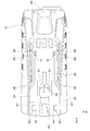
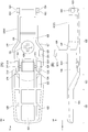
- FIG. 2 It is a side view seen from the left side which shows the disc grinder which concerns on this embodiment. It is a bottom view seen from the lower side which shows the rear part of the disc grinder shown in FIG. It is a side sectional view seen from the left side which shows the inside of the disc grinder shown in FIG. It is the bottom view which looked at the rear housing shown in FIG. 2 from the lower side. It is a layout diagram seen from the lower side schematically showing the arrangement state of the motor side lead wire and the substrate side lead wire for connecting the motor and the control board shown in FIG. (A) is a cross-sectional view (cross-sectional view taken along the line 6A-6A of FIG. 2) showing a state in which the stopper portion of the rear housing shown in FIG.
- B) is a perspective view of the inserted state of the stopper portion shown in (A) into the stopper insertion portion as viewed from diagonally upper left. It is a cross-sectional view (7-7 line cross-sectional view of FIG. 2) seen from the front side which shows the state which the rotation shaft of the paddle lever shown in FIG. 2 is inserted into the support hole of a rear housing.
- (A) is a plan view of the paddle lever shown in FIG. 2 as viewed from above
- (B) is a side view of the paddle lever of (A) as viewed from the left side.
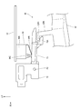
- FIG. 8 is a cross-sectional view taken from diagonally upper right side showing an intermediate portion in the longitudinal direction of the huddle lever shown in FIG. It is a figure which shows the process of attaching a huddle lever. It is a side view seen from the left side which shows the operation mechanism part of the disc grinder shown in FIG.
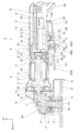
- a disc grinder 10 (hereinafter, simply referred to as a grinder 10) as a working machine according to the present embodiment will be described with reference to the drawings.
- the arrows UP, FR, and RH appropriately shown in the drawings indicate the upper side, the front side, and the right side of the grinder 10, respectively.
- the grinder 10 is indicated in the vertical direction, the front-back direction, and the left-right direction unless otherwise specified. Further, the left-right direction corresponds to the orthogonal direction of the present invention.
- the grinder 10 is configured as a tool for performing cutting, polishing, or the like on a work material. As shown in FIGS. 1 to 3, the grinder 10 includes a housing 20, a motor 30, a transmission mechanism 50, an operation mechanism unit 60, and a control unit 80. Hereinafter, each configuration of the grinder 10 will be described.
- the housing 20 constitutes the outer shell of the grinder 10 and is formed as a hollow substantially cylindrical shape extending in the front-rear direction as a whole.
- the housing 20 includes a motor housing 22 as a first housing forming an intermediate portion in the front-rear direction of the housing 20, a gear housing 24 forming a front end portion of the housing 20, and a second housing forming a rear end portion of the housing 20.
- the rear housing 26 and the rear housing 26 of the above are included. Further, inside the rear housing 26, a board holder 28 for holding the control board 82 of the control unit 80, which will be described later, is provided.
- the motor housing 22 is formed in a substantially cylindrical shape with the front-rear direction as the axial direction.
- the inside of the motor housing 22 is configured as a motor accommodating portion 22A for accommodating the motor 30 described later.
- a diameter-expanded portion 22B extending outward in the radial direction is formed at the front end portion of the motor housing 22, and the diameter-expanded portion 22B is formed in a substantially rectangular shape when viewed from the front.
- a fan 42 which will be described later, is housed in the enlarged diameter portion 22B.
- a bearing accommodating portion 22C for accommodating the second motor bearing 36, which will be described later, is formed inside the rear end portion of the motor housing 22.
- the bearing accommodating portion 22C is formed in a substantially cylindrical shape with the front-rear direction as the axial direction, and is arranged coaxially with the motor housing 22.
- the bearing accommodating portion 22C is connected to the side wall portion of the motor housing 22 by a connecting rib (not shown) provided around the bearing accommodating portion 22C.
- a pair of upper and lower holder fixing portions 22D for fixing the substrate holder 28, which will be described later, are formed on the radial outer side of the bearing accommodating portion 22C.
- the holder fixing portion 22D is formed in a substantially cylindrical shape with the front-rear direction as the axial direction, and is connected to the bearing accommodating portion 22C and the motor housing 22. Further, a female screw is formed on the inner peripheral portion of the holder fixing portion 22D.
- the rear end portion of the motor housing 22 is inclined forward as it goes downward in a side view.
- a step portion 22E is formed on the outer peripheral portion of the rear end portion of the motor housing 22, and the step portion 22E is lowered one step inward in the radial direction from the outer peripheral portion of the motor housing 22. Further, the step portion 22E is formed over the entire circumference of the rear end portion of the motor housing 22.
- the gear housing 24 has a base portion 24A constituting the rear end portion of the gear housing 24, and the base portion 24A is formed in the motor housing 22 in a substantially rectangular tubular shape corresponding to the enlarged diameter portion 22B. Has been done. Then, the enlarged diameter portion 22B is inserted into the base portion 24A, and the outer peripheral portion of the base portion 24A is fixed to the enlarged diameter portion 22B at a position (not shown). Further, the gear housing 24 is formed with an overhanging portion 24B extending forward from the base portion 24A, and the overhanging portion 24B is formed in a substantially triangular shape in a side view and is opened downward. ing.
- the substrate holder 28 is formed in a substantially long box shape that is open downward and extends in the front-rear direction. ing.
- a pair of upper and lower fixed portions 28A are formed on the front wall of the board holder 28 at positions corresponding to the holder fixing portions 22D of the motor housing 22, and the fixed portions 28A are substantially axially oriented in the front-rear direction. It is formed in a cylindrical shape. Then, the fixing screw SC1 is inserted into the fixed portion 28A from the rear side and screwed into the female screw of the holder fixing portion 22D, so that the substrate holder 28 is fixed to the motor housing 22.
- a fixing boss 28B (see FIG. 5) for fixing the rear housing 26, which will be described later, to the motor housing 22 is formed at the rear end of the board holder 28.
- the fixed boss 28B is formed in a substantially cylindrical shape with the front-rear direction as the axial direction, and a female screw is formed on the inner peripheral portion of the fixed boss 28B.
- a fixing screw SC2 can be screwed into the fixing boss 28B.
- the rear housing 26 can be fixed to the motor housing 22 by fixing the rear housing 26 to the board holder 28 fixed to the motor housing 22 using the fixing screws SC2.
- the rear housing 26 is made of resin and is formed in a substantially bottomed cylindrical shape that is open to the front side.
- the inside of the rear housing 26 is configured as a substrate accommodating portion 26A.
- a fixing hole (not shown) is formed through the rear wall of the rear housing 26 at a position corresponding to the fixing boss 28B of the substrate holder 28.
- the fixing screw SC2 is inserted into the fixing hole from the rear side and screwed into the fixing boss 28B to fix the rear housing 26 to the board holder 28.
- the front end portion of the rear housing 26 is extrapolated to the stepped portion 22E of the rear end portion of the motor housing 22. That is, the board holder 28 fixes the rear housing 26 and also functions as a member for connecting the rear housing 26 to the motor housing 22.
- the front end surface of the rear housing 26 is inclined forward as it goes downward in a side view.
- a protruding portion 26B protruding downward is formed at the rear end portion of the rear housing 26.
- the protrusion 26B is formed in a substantially trapezoidal block shape when viewed from the side.
- a surrounding wall 26C protruding downward is formed on the front side of the protruding portion 26B, and the surrounding wall 26C is opened to the front side when viewed from the lower side. It is formed in a substantially U-shape.
- the space surrounded by the surrounding wall 26C is configured as a lever accommodating portion 26D for accommodating the paddle lever 62 described later, and the lever accommodating portion 26D is open to the lower side and the front side.
- bent portions 26E are formed at intermediate portions in the front-rear direction of the left and right side walls of the surrounding wall 26C.
- the bent portion 26E is bent in a substantially crank shape when viewed from below, and the width dimension (left-right direction dimension) of the front portion of the lever accommodating portion 26D is larger than the width dimension of the rear portion of the lever accommodating portion 26D. Is set to.
- the paddle lever 62 which will be described later, is located above the straight line connecting the lower end of the protrusion 26B and the rear end of the grindstone 53, so that the paddle lever 62 comes into contact with the ground or the like. It can be suppressed.
- a pair of left and right stopper portions 26F are formed at the front end portion of the lever accommodating portion 26D on the lower outer peripheral portion of the rear housing 26.
- the pair of stopper portions 26F are arranged at positions symmetrical with respect to the central portion in the left-right direction of the rear housing 26.
- the stopper portion 26F is formed in a substantially long plate shape extending in the vertical direction with the horizontal direction being the plate thickness direction, and extends downward from the rear housing 26.
- Reinforcing ribs 26F1 are formed at the rear end of the stopper portion 26F, and the reinforcing ribs 26F1 project outward from the stopper portion 26F in the left-right direction and extend in the up-down direction. That is, in the stopper portion 26F on the right side, the reinforcing rib 26F1 protrudes to the right from the stopper portion 26F, and in the stopper portion 26F on the left side, the reinforcing rib 26F1 protrudes to the left from the stopper portion 26F. Further, an engaging portion 26F2 is formed at the tip end portion (lower end portion) of the stopper portion 26F. The engaging portion 26F2 projects outward from the stopper portion 26F in the left-right direction, and the rear end portion of the engaging portion 26F2 is connected to the reinforcing rib 26F1.
- a contact portion 26G configured to be in contact with an off-lock member 66, which will be described later, is formed between the pair of stopper portions 26F on the lower outer peripheral portion of the rear housing 26. There is.
- the contact portion 26G is formed in a substantially U shape that is open to the front side when viewed from the lower side, and protrudes downward from the rear housing 26.
- an insertion hole 26H is formed through the outer peripheral portion of the rear housing 26 on the rear side of the stopper portion 26F on the left side. That is, the insertion hole 26H is arranged closer to the left side with respect to the center portion in the left-right direction of the rear housing 26.
- the insertion hole 26H is formed in a substantially rectangular shape with the front-rear direction as the longitudinal direction when viewed from below, and is arranged adjacent to the inside of the side wall of the surrounding wall 26C in the left-right direction.
- a pair of left and right spring mounting portions 26J for mounting the lever urging spring 64 are formed on the rear side of the contact portion 26G.
- the spring mounting portion 26J is formed in a substantially L-shape that is open to the front side and inward in the left-right direction when viewed from the lower side, and protrudes downward from the rear housing 26. Further, on the outer peripheral portion of the rear housing 26, a spring locking portion 26K is formed between the pair of spring mounting portions 26J, and the spring locking portion 26K is a substantially cross (plus sign) when viewed from below. It is formed in a shape and protrudes downward from the rear housing 26.
- a pair of left and right support portions 26L that rotatably support the paddle lever 62, which will be described later, are formed at the rear end portion of the side wall of the surrounding wall 26C. ..
- the pair of left and right support portions 26L are configured to be indivisible.
- the support portion 26L projects inward in the left-right direction from the inner peripheral surface of the surrounding wall 26C.
- a circular support hole 26M is formed through the support portion 26L in the left-right direction.
- a housing-side inclined surface 26N as an inclined portion is formed below the support hole 26M.
- the housing-side inclined surface 26N is inclined outward in the left-right direction as it goes downward when viewed from the front-rear direction.
- a regulation rib 26P as a regulation portion is formed on the lower inner peripheral surface of the rear housing 26.
- the regulation rib 26P has a plate thickness direction in the left-right direction and extends in the front-rear direction.
- the regulation rib 26P is arranged adjacent to the right side of the insertion hole 26H and projects upward from the inner peripheral surface of the rear housing 26.
- the front end portion of the regulation rib 26P is located on the right side of the intermediate portion in the front-rear direction of the insertion hole 26H, and the rear end portion of the regulation rib 26P is connected to the rear wall of the rear housing 26.
- the lower end portion of the substrate accommodating portion 26A is partitioned in the left-right direction by the regulation rib 26P.
- the region on the right side with respect to the regulation rib 26P at the lower end portion of the substrate accommodating portion 26A is configured as the wiring accommodating region 26A1 (see FIG. 6A), and the regulation rib at the lower end portion of the substrate accommodating portion 26A.
- the region on the left side of 26P is configured as the lever operating region 26A2 (see FIG. 6A).
- a plurality of intake ports 26R are formed through the left and right side portions of the rear housing 26.
- the intake ports 26R have a plurality of intake ports 26R arranged substantially in the vertical direction as one set, and five sets of intake ports 26R are arranged side by side in the front-rear direction.
- the motor 30 is configured as a three-phase brushless motor and is housed in the motor housing portion 22A of the motor housing 22.
- the motor 30 includes a rotor 32 and a stator 33, and a rotating shaft 31 is attached to the rotor 32.
- the rotation shaft 31 is arranged with the front-rear direction as the axial direction.
- the front end of the rotating shaft 31 is rotatably supported by the first motor bearing 35 fixed to the gear housing 24, and the rear end of the rotating shaft 31 is fixed to the bearing accommodating portion 22C of the motor housing 22. It is rotatably supported by a second motor bearing 36.
- the rotor 32 is arranged on the outer side in the radial direction of the rotating shaft 31, and is configured to be integrally rotatable with the rotating shaft 31.
- the stator 33 is formed in a substantially cylindrical shape with the front-rear direction as the axial direction, and is supported by the motor housing 22 on the radial outer side of the rotor 32.
- the stator 33 has a stator holder, and a stator coil corresponding to the U phase, V phase, and W phase of the motor 30 is wound around the stator holder.
- the lead wires 38A, 38B, and 38C on the motor side as electrical components and wiring, respectively (see the lead wires painted in gray in FIG. 5). ) Is connected.
- the motor-side lead wires 38A, 38B, and 38C are arranged below the bearing accommodating portion 22C of the motor housing 22, and are arranged in the wiring accommodating area 26A1 of the rear housing 26. That is, the motor-side lead wires 38A, 38B, and 38C extend in the front-rear direction in the wiring accommodation area 26A1 of the rear housing 26. Further, the other ends of the motor-side lead wires 38A, 38B, and 38C are connected to the electrical components and the substrate-side lead wires 40A, 40B, 40C as wirings (see the lead wires painted in black in FIG. 5). ), And the board-side lead wires 40A, 40B, and 40C are connected to the control board 82 of the control unit 80, which will be described later.
- the motor 30 is configured to be driven by the control unit 80.
- the substrate-side lead wires 40A, 40B, 40C are arranged in the wiring accommodation area 26A1 in the same manner as the motor-side lead wires 38A, 38B, 38C.
- a fan 42 is integrally rotatable on the rear side of the first motor bearing 35 on the front end side portion of the rotating shaft 31.
- the fan 42 is configured as an axial fan.
- the fan 42 is configured to generate an air flow from the rear side to the front side.
- air flows into the housing 20 from the intake port 26R of the rear housing 26, and the air is discharged from the exhaust port (not shown) formed in the overhanging portion 24B of the gear housing 24. Therefore, the control unit 80 and the motor 30, which will be described later, are cooled by the air flow generated by the fan 42.
- the front end portion of the rotating shaft 31 is housed in the overhanging portion 24B of the gear housing 24, and the pinion gear 44 is fixed to the front end portion of the rotating shaft 31.
- the gear teeth of the pinion gear 44 are inclined inward in the radial direction of the rotating shaft toward the front side.
- the transmission mechanism 50 has an output shaft 51 whose axial direction is the vertical direction, and the output shaft 51 is housed in the overhanging portion 24B of the gear housing 24.
- the vertical intermediate portion of the output shaft 51 is rotatably supported by a bearing 52 fixed to the gear housing 24.
- the lower end of the output shaft 51 is configured as a tool mounting portion 51A, and a male screw is formed on the outer peripheral portion of the tool mounting portion 51A.
- a disk-shaped grindstone 53 as a tool is attached to the tool attachment portion 51A.
- the grindstone 53 is mounted on the tool mounting portion 51A by externally inserting the mounting hole 53A of the grindstone 53 into the tool mounting portion 51A and screwing the nut N into the tool mounting portion 51A.
- the outer peripheral portion of the grindstone 53 is partially covered with the foil guard 55.
- the wheel guard 55 is configured so that a portion having a large number of grindstones 53 can be arbitrarily changed, and in the states of FIGS. 1 and 3, the wheel guard 55 is in a position of covering the rear portion of the grindstone 53.
- a bevel gear 54 is fixed to the upper end of the output shaft 51, and the bevel gear 54 is meshed with the pinion gear 44. As a result, when the motor 30 is driven, the rotation of the motor 30 is transmitted to the output shaft 51, and the grindstone 53 rotates around the axis of the output shaft 51.
- the operation mechanism unit 60 includes a paddle lever 62 as a lever, an off-lock member 66, and an interlocking lever 70. It is configured.
- the paddle lever 62 is made of resin and is formed in a substantially rectangular concave shape that is open upward and extends in the front-rear direction.
- the paddle lever 62 includes a bottom wall 62A and a peripheral wall 62B protruding upward on the outer peripheral portion of the bottom wall 62A.
- a lever step portion 62C is formed in the middle portion in the front-rear direction of the bottom wall 62A, and the lever step portion 62C is substantially bent on the crank in a side view and is inclined upward as it goes to the front side. ..
- the portion of the paddle lever 62 on the front side of the lever step portion 62C is configured as the lever grip portion 62D, and the portion of the paddle lever 62 on the rear side of the lever step portion 62C is configured as the lever body portion 62E (lever center portion).
- the lever grip portion 62D is configured as a portion to be gripped by the user, and the wall thickness of the lever grip portion 62D is set to be thinner than the wall thickness of the lever main body portion 62E.
- a pair of left and right bent portions 62F are formed on the rear side of the lever step portion 62C at the intermediate portion in the front-rear direction of the peripheral wall 62B.
- the bent portion 62F is bent in a substantially crank shape when viewed from below, and the width dimension (dimension in the left-right direction) of the rear end portion of the lever body portion 62E is set to be smaller than the width dimension of the other portion. Has been done.
- a pair of left and right rotating shafts 62G are formed at the rear end of the side wall of the peripheral wall 62B.
- the rotating shaft 62G is formed in a substantially columnar shape with the left-right direction as the axial direction, and projects outward from the peripheral wall 62B in the left-right direction (outside in the width direction of the paddle lever 62).
- the rear end portion of the paddle lever 62 is accommodated in the lever accommodating portion 26D of the rear housing 26, and the rotating shaft 62G is inserted into the support hole 26M of the rear housing 26 from the inside in the left-right direction to enter the support hole 26M. It is rotatably supported.
- the paddle lever 62 is rotatably connected to the rear housing 26.
- the paddle lever 62 is shown at the initial position (the position shown by the solid line in FIG. 1) and the operation position rotated clockwise from the initial position when viewed from the left side (shown by the alternate long and short dash line in FIG. 1). It is configured to rotate between (position) and. Then, in the initial position, the paddle lever 62 is tilted downward toward the front side, and in the operating position, the paddle lever 62 is set to be substantially horizontal. Further, in the connected state of the paddle lever 62 to the rear housing 26, the lever grip portion 62D of the paddle lever 62 extends forward from the lever accommodating portion 26D and is arranged below the motor housing 22. This allows the operator to operate the paddle lever 62 while grasping the motor housing 22 that does not have the intake port 26R.
- a shaft-side inclined surface 62H as an inclined portion is formed on the upper portion of the tip surface of the rotating shaft 62G.
- the axial side inclined surface 62H is inclined inward in the left-right direction as it goes upward when viewed from the front-rear direction.
- the rotation shaft 62G is arranged below the housing-side inclined surface 26N of the rear housing 26 (the paddle lever 62 shown by the chain double-dashed line in FIG. 7).
- the shaft-side inclined surface 62H slides on the housing-side inclined surface 26N, and the peripheral wall 62B of the paddle lever 62 and the surrounding wall 26C of the rear housing 26 are bent and deformed.
- the rotating shaft 62G is configured to be fitted into the support hole 26M. That is, by so-called snap-fit fitting, the rotating shaft 62G is rotatably fitted into the support hole 26M.
- the housing-side inclined surface 26N and the shaft-side inclined surface 62H are configured as functional portions for promoting snap-fit fitting between the rotating shaft 62G and the support hole 26M.
- a pair of left and right stopper insertion portions 62J are formed on the bottom wall 62A of the paddle lever 62 on the rear side of the lever step portion 62C.
- the stopper insertion portion 62J is arranged at a position corresponding to the stopper portion 26F of the rear housing 26 described above.
- the stopper insertion portion 62J is formed in a substantially rectangular tubular shape with the vertical direction in the axial direction, and the outer wall portion in the left-right direction of the stopper insertion portion 62J is formed by a peripheral wall 62B.
- the inside of the stopper insertion portion 62J is configured as an insertion hole 62J1 as a hole portion, and the insertion hole 62J1 penetrates in the vertical direction.
- the upper opening of the stopper insertion portion 62J is provided with an engaged portion 62J2 at a corner portion on the front side and on the outer side in the left-right direction.
- the engaged portion 62J2 is formed in a substantially rectangular plate shape with the vertical direction being the plate thickness direction and the front-rear direction and the longitudinal direction.
- the upper opening of the stopper insertion portion 62J is formed in a substantially L shape.
- the front side is partially closed by the engaged portion 62J2 so as to be narrow in the left-right direction and wide on the rear side.
- the stopper portion 26F of the rear housing 26 is inserted into the insertion hole 62J1 of the stopper insertion portion 62J from the upper opening of the stopper insertion portion 62J. Further, in the state where the stopper portion 26F is inserted into the stopper insertion portion 62J, the stopper portion 26F is arranged inside the engaged portion 62J2 in the left-right direction, and the engaging portion 26F2 of the stopper portion 26F is engaged. It is arranged adjacent to the lower side of 62J2. As a result, the engaging portion 26F2 and the engaged portion 62J2 are engaged (contacted) in the vertical direction, and the downward rotation of the paddle lever 62 at the initial position is restricted.
- the state in which the engaging portion 26F2 and the engaged portion 62J2 are engaged is the initial position of the paddle lever 62. Further, the stopper portion 26F is sandwiched in the left-right direction by the inner peripheral surface of the stopper insertion portion 62J (specifically, the inner peripheral surface inside in the left-right direction) and the engaged portion 62J2. Therefore, the stopper insertion portion 62J and the engaged portion 62J2 are configured to limit the displacement of the stopper portion 26F in the left-right direction. That is, the pair of left and right stoppers 26F suppresses the paddle lever 62 from swinging, deforming, or bending in the left-right direction.
- a spring seat portion 62K is formed at the rear portion of the bottom wall 62A of the paddle lever 62.
- the spring seat portion 62K is arranged on the rear side of the stopper insertion portion 62J and at the center portion in the left-right direction of the paddle lever 62.
- the spring seat portion 62K is formed in a substantially columnar shape with the vertical direction as the axial direction, and projects upward from the bottom wall 62A.
- a lever urging spring 64 (see FIG. 3) as a spring is mounted on the spring seat portion 62K.
- the lever urging spring 64 is configured as a compression coil spring, and the lower end of the lever urging spring 64 is locked to the spring seat portion 62K.
- the upper end portion of the lever urging spring 64 is arranged between the pair of spring mounting portions 26J in the rear housing 26 and is locked to the rear housing 26.
- the paddle lever 62 is urged downward and held in the initial position by the urging force of the lever urging spring 64.
- a spring locking portion 62L is formed on the upper surface of the spring seat portion 62K, and the spring locking portion 62L is formed in a substantially cross (plus sign) shape when viewed from above.
- the spring locking portion 26K of the rear housing 26 and the spring locking portion 62L of the paddle lever 62 are arranged inside the lever urging spring 64 to limit the movement of the lever urging spring. ..
- FIG. 10 is a diagram showing a process of attaching the paddle lever 62 to the rear housing 26.
- the engaging portion 26F2 is opened to the upper side of the stopper insertion portion 62J as shown in FIG. 10 (A). Insert from the part.
- the upper opening of the stopper insertion portion 62J is partially closed by the engaged portion 62J2, and the engaging portion 26F2 cannot pass through this closed region, so that the engaging portion 26F2 is engaged.
- the engaging portion 26F2 is positioned under the engaged portion 62J2.
- the reinforcing rib 26F1 is located behind the engaged portion 62J2 to prevent the paddle lever 62 from moving backward more than necessary. .. That is, the reinforcing rib 26F1 not only improves the durability of the stopper portion 26F itself, but also functions as an auxiliary member when assembling the paddle lever 62 to the rear housing 26.
- the rotation shaft 62G and the support hole 26M are in the same position in the front-rear direction, and are in a positional relationship in which they can be engaged with each other.
- the rotating shaft 62G is engaged with the support hole 26M by the snap-fit fitting described above (the state shown in FIG. 10C). ).
- the paddle lever 62 is separated from the rear housing 26 by the engagement between the engaged portion 62J2 and the engaging portion 26F2 (the direction in which the paddle lever 62 is separated from the rear housing 26 ().
- an arrangement hole 62M for arranging the off-lock member 66 described later is formed through the bottom wall 62A of the paddle lever 62 between the pair of stopper insertion portions 62J.
- the arrangement hole 62M is formed in a substantially rectangular shape in a plan view.
- a pair of left and right bearing portions 62N are formed on the bottom wall 62A of the paddle lever 62, and the bearing portions 62N are arranged between the arrangement hole 62M and the stopper insertion portion 62J, and from the bottom wall 62A. It protrudes upward.
- a bearing groove 62P is formed in the bearing portion 62N, and the bearing groove 62P is open on the upper side and inward in the left-right direction. Further, support pins P1 (see FIGS. 6A and 6B) having an axial direction in the left-right direction are bridged to the pair of bearing portions 62N, and both ends in the longitudinal direction of the support pins P1 are bearings. It is fitted in the lower end of the groove 62P.
- a switch operating portion 62R for operating a switch 84 which will be described later, is provided on the peripheral wall 62B on the left side of the paddle lever 62.
- the switch operating portion 62R is formed in a substantially rectangular columnar shape with the vertical direction as the axial direction, and extends upward from the peripheral wall 62B. Further, the upper portion of the switch operating portion 62R is arranged in the lever operating region 26A2 of the rear housing 26 by inserting the inside of the insertion hole 26H of the rear housing 26 from below. That is, the switch operating portion 62R is arranged adjacent to the left side of the regulation rib 26P.
- An actuating protrusion 62R1 is formed at the upper end of the switch actuating portion 62R, and the actuating protrusion 62R1 projects forward from the switch actuating portion 62R.
- the off-lock member 66 is formed in a substantially rectangular plate shape with the front-rear direction as the plate thickness direction, and is viewed from the left-right direction. It is bent in a substantially crank shape. Specifically, the upper end portion of the off-lock member 66 is arranged on the front side of the lower end portion of the off-lock member 66. A lock support portion 66A projecting to the front side is formed in the vertical intermediate portion of the off-lock member 66. Then, the off-lock member 66 is arranged in the arrangement hole 62M of the paddle lever 62, and the lock support portion 66A is rotatably supported by the support pin P1. That is, the off-lock member 66 is rotatably connected to the paddle lever 62, and the off-lock member 66 and the pair of stopper insertion portions 62J are arranged side by side in the left-right direction.
- a lock spring 68 configured as a torsion spring is mounted on the support pin P1, and the lock spring 68 urges the off-lock member 66 counterclockwise when viewed from the left side.
- the off-lock member 66 When the off-lock member 66 is connected to the paddle lever 62, the lower end of the off-lock member 66 projects downward from the paddle lever 62. As a result, the lower part of the off-lock member 66 comes into contact with the rear surface of the arrangement hole 62M by the urging force of the lock spring 68, and the off-lock member 66 is held at the lock position (the position shown by the solid line in FIG. 3). ing.
- the upper end portion of the off-lock member 66 is arranged close to the lower side of the contact portion 26G of the rear housing 26. Therefore, when the paddle lever 62 is to be rotated from the initial position to the operation position side, the upper end portion of the off-lock member 66 comes into contact with the contact portion 26G, so that the paddle lever 62 is rotated from the initial position to the operation position side.
- the structure is such that movement is blocked.
- the off-lock member 66 when the off-lock member 66 is rotated clockwise from the lock position, the upper end portion of the off-lock member 66 is displaced downward with respect to the contact portion 26G (at the position indicated by the alternate long and short dash line in FIG. 3). Yes, this position is referred to as the unlock position below). As a result, by rotating the off-lock member 66 to the unlocked position, the paddle lever 62 can be rotated from the initial position to the operating position side.
- the interlocking lever 70 is formed in a substantially long shape extending in the front-rear direction, and is a lever operating region of the rear housing 26 (not shown in FIG. 11). It is arranged in 26A2. Specifically, the rear end portion of the interlocking lever 70 is arranged adjacent to the upper side of the switch operating portion 62R of the paddle lever 62, and the interlocking lever 70 is rearward of the motor housing 22 (not shown in FIG. 11). It is arranged so as to straddle the end portion and the front end portion of the rear housing 26.
- the front end of the interlocking lever 70 is connected to a lever holder 72 provided inside the motor housing 22. Specifically, the lever holder 72 is provided with a support pin P2 whose axial direction is the left-right direction, and the front end portion of the interlocking lever 70 is rotatably supported by the support pin P2.
- a lever connecting portion 70A is formed at the rear end portion of the interlocking lever 70.
- the lever connecting portion 70A protrudes downward from the interlocking lever 70 and bends rearward.
- the actuating protrusion 62R1 of the paddle lever 62 is inserted between the rear end portion of the interlocking lever 70 and the lever connecting portion 70A.
- the interlocking lever 70 and the paddle lever 62 are engaged (contacted) in both the upper and lower directions. Therefore, when the paddle lever 62 rotates between the initial position and the operating position, the interlocking lever 70 is moved to the paddle lever 62. It is configured to rotate around the axis of the support pin P2 in conjunction with the rotation.
- the interlocking lever 70 in the initial position of the paddle lever 62, the interlocking lever 70 is arranged in the non-pressing position (position shown in FIG. 11), and in the operating position of the paddle lever 62, the interlocking lever 70 is moved from the non-pressing position. It is configured to be arranged at a pressing position (not shown) rotated upward. Due to the above engagement relationship, when the paddle lever 62 is in the initial position, the interlocking lever 70 is also in the downward rotation position (non-pressing position in FIG. 11), so that the switch portion 84C described later is pressed. It can be suppressed that it is maintained by.
- the control unit 80 has a control board 82, and the control board 82 has a plate thickness direction in the vertical direction and a longitudinal direction in the front-rear direction. It is formed in the shape of a substantially rectangular plate.
- the control board 82 is arranged inside the board holder 28 and is held by the board holder 28. Specifically, the control board 82 is housed in the upper part of the board housing portion 26A of the rear housing 26. As a result, the above-mentioned regulation rib 26P of the rear housing 26 is arranged on the lower side (one side in the plate thickness direction) of the control board 82.
- a switch 84 as an electrical component for turning on / off the motor 30 is provided on the lower surface (one side surface) of the control board 82, and the switch 84 is arranged above the front portion of the interlocking lever 70 described above. (See FIG. 11). Specifically, in the vertical direction, the regulation rib 26P of the rear housing 26 and a part of the switch 84 (right end) are arranged to face each other, and the left portion of the switch 84 and the interlocking lever 70 are arranged to face each other. (See FIG. 6 (A)).
- the switch 84 is configured as a lever type switch.
- the switch 84 includes a switch body 84A mounted on the control board 82, a lever portion 84B rotatably connected to the switch body 84A, and a switch portion 84C pressed by the lever portion 84B. It is composed of.
- the lever portion 84B is in contact with the upper surface of the interlocking lever 70 (see FIG. 11).
- the interlocking lever 70 rotates from the non-pressed position to the pressed position in conjunction with the rotation of the paddle lever 62, so that the lever portion 84B presses the switch portion 84C of the switch body 84A and the switch 84 is turned off. It is configured to switch from to on.
- the substrate-side lead wires 40A, 40B, and 40C described above are connected to the control substrate 82, and the control substrate 82 and the motor 30 are electrically connected.
- a plurality of (six in the present embodiment) switching elements 86 as electrical components are provided on the lower surface (one side surface) of the control board 82, and the switching elements 86 include the lead wires 38A and 38B on the motor side. It is electrically connected to the stator coil of the motor 30 by 38C and the lead wires 40A, 40B, 40C on the substrate side. Further, the switching element 86 constitutes an inverter circuit for switching the energized state of the stator coil in the motor 30.
- the switching element 86 is composed of three switching elements 86 as a set, and the switching elements 86 forming the set are arranged side by side in the front-rear direction. Then, two sets of switching elements 86 are arranged side by side in the left-right direction. Specifically, two sets of switching elements 86 are arranged on the right side of the switch 84 and the regulation rib 26P. As a result, the motor-side lead wires 38A, 38B, 38C and the substrate-side lead wires 40A, 40B, 40C arranged in the wiring accommodation area 26A1 are arranged below the switching element 86.
- the switching element 86 arranged on the left side is arranged close to the right side of the switch 84 and the regulation rib 26P. Further, the tip end portion (lower end portion) of the switching element 86 is arranged below the tip end portion (upper end portion) of the regulation rib 26P. That is, when viewed from the left-right direction, the tip portion of the switching element 86 and the tip portion of the regulation rib 26P are arranged so as to overlap each other.
- the switching element 86 and the regulation rib 26P restrict the motor-side lead wires 38A, 38B, 38C and the substrate-side lead wires 40A, 40B, 40C from moving from the wiring accommodation area 26A1 to the lever operating area 26A2 side. It is configured.
- the regulation rib 26P is configured so as to overlap with the particularly tall switching element 86, but it is configured to overlap with electrical components such as a capacitor for smoothing and a diode bridge for rectification, for example. May be good.
- the gap between the tip of the switching element 86 and the tip of the regulation rib 26P in the left-right direction is smaller than the thickness of the motor-side lead wires 38A, 38B, 38C and the substrate-side lead wires 40A, 40B, 40C. It is composed of. As a result, it is possible to prevent these lead wires from passing between the switching element 86 and the regulation rib 26P, and it is possible to more preferably suppress the movement of the lead wires to the lever operating region 26A2 side.
- a power cord 88 is connected to the control board 82, and the power cord 88 extends from the rear end of the rear housing 26 to the rear side.
- the power cord 88 is configured to be connectable to an AC power supply. As a result, electric power is supplied to the motor 30.
- the paddle lever 62 is arranged at the initial position and the interlocking lever 70 is arranged at the non-pressing position. Further, in this state, the off-lock member 66 is arranged at the locked position. Therefore, the off-lock member 66 prevents the paddle lever 62 from rotating toward the operating position.
- the off-lock member 66 When the grinder 10 is operated, the off-lock member 66 is rotated from the locked position to the unlocked position. This allows the paddle lever 62 to rotate from the initial position to the operating position. In this state, when the paddle lever 62 is rotated from the initial position to the operating position, the interlocking lever 70 rotates from the non-pressed position to the pressed position in conjunction with the rotation of the paddle lever 62, and the switch 84 is turned off. Switch from to on. As a result, the motor 30 is driven by the control of the control unit 80. Specifically, the rotation shaft 31 of the motor 30 rotates, and the output shaft 51 of the transmission mechanism 50 rotates. As a result, the grindstone 53 attached to the output shaft 51 rotates. Therefore, the processed material can be cut or polished.
- a rotating shaft 62G is integrally provided on the paddle lever 62, and the rotating shaft 62G is rotatably connected to the rear housing 26. Further, the rear housing 26 is integrally formed with a stopper portion 26F for regulating the rotation range of the paddle lever 62.
- the rear housing 26 and the paddle lever 62 are each composed of a single member. As a result, the assembling property of the grinder 10 can be improved.
- the paddle lever 62 It is necessary to connect the front end portion of 62 to the motor housing 22, and to engage the stopper portion 26F and the paddle lever 62 while assembling the rear housings 26 divided into two parts.
- the grinding machine of the comparative example it is necessary to assemble the paddle lever 62 to the two members of the motor housing 22 and the rear housing 26.
- the grinding machine of the comparative example it is necessary to assemble the two divided members of the rear housing 26.
- the assembling becomes complicated and the assembling property may be deteriorated.
- the rear housing 26 and the paddle lever 62 are composed of a single member, and the paddle lever 62 is rotatably connected to the rear housing 26. Therefore, the paddle lever 62 and the rear housing 26 can be unitized by engaging the paddle lever 62 with the stopper portion 26F of the rear housing 26 while connecting the paddle lever 62 to the rear housing 26. That is, unlike the grinding machine of the comparative example, it is not necessary to assemble the paddle lever 62 to the two members of the motor housing 22 and the rear housing 26. Further, since the rear housing 26 is composed of a single member, it is not necessary to assemble the rear housings 26 divided into two parts as in the grinding machine of the comparative example.
- the assembly man-hours can be significantly reduced as compared with the grinding machine of the comparative example. Then, the rear housing 26 and the paddle lever 62 in the unit state can be assembled to the motor housing 22. Therefore, the assembling property of the grinder 10 can be improved.
- the volume of the substrate accommodating portion 26A of the rear housing 26 can be increased as compared with the configuration in which the rear housing 26 is divided. , Can contribute to the miniaturization of the physique of the grinder 10. That is, if the rear housing 26 is divided in the left-right direction, it is necessary to provide a fixing portion for fixing the two divided rear housings 26 inside or outside the rear housing 26. When the fixing portion is provided inside the rear housing 26, the volume of the substrate accommodating portion 26A tends to decrease. Further, when the fixing portion is provided outside the rear housing 26, the physique of the grinder 10 tends to increase in size.
- At least a part (rear housing 26) of the housing constituting the grinder 10 is composed of a single indivisible member, and the part is a single member. It is configured as a support portion that supports the paddle lever 62 of the member. That is, the housing constituting the grinder 10 has an indivisible support portion for supporting the paddle lever 62 having the rotating shaft integrally. Therefore, it is not necessary to provide the fixing portion inside or outside the rear housing 26. Therefore, the volume of the substrate accommodating portion 26A of the rear housing 26 can be increased and the size of the grinder 10 can be reduced as compared with the configuration in which the rear housing 26 is divided.
- the switch 84 pressed by the paddle lever 62 is supported by the motor housing 22, and the paddle lever 62 is supported by the rear housing 26.
- the rear housing 26 in which the paddle lever 62 is supported can be assembled to the motor housing 22 in which the switch 84 (board holder 28) is supported. That is, since the paddle lever 62 and the unitized rear housing 26 can be assembled to the motor housing 22 unitized with the electrical components such as the switch 84, two units are operated when assembling these.
- the fixing screw SC2 may be screwed into the fixing boss 28B via the rear housing 26 while being connected, that is, the assembly can be performed by a simple operation such as screwing the two parts. Very good assembling.
- control board 82 and the electrical components mounted on the control board 82 are arranged so as not to interfere with the assembly of the rear housing 26. More specifically, when the rear housing 26 is connected so as to move toward the rear portion of the motor housing 22 (from the rear to the front) and accommodate the control board 82 and the like, the inner surface of the rear housing 26 and the regulation ribs are used.
- the structure is such that the 26P, the control board 82, and the electrical components (switching element 86, etc.) mounted on the control board 82 do not interfere with each other due to contact or the like and do not interfere with the assembly.
- the number of parts is reduced by using the rear housing 26 as a single member, but the effect of improving the assembling property by the above-mentioned two unitization is that the rear housing 26 is a split type housing. It has the same effect.
- the rear end portion of the paddle lever 62 is rotatably connected to the rear housing 26, and the lever grip portion 62D constituting the front end portion of the paddle lever 62 is on the lower side of the motor housing 22. Is located in. Therefore, the workability of the grinder 10 can be improved. That is, if the front end portion of the paddle lever 62 is rotatably connected to the motor housing 22, the rear end portion of the paddle lever 62 is configured as a grip portion to be gripped by the user.
- a grindstone 53 is attached to the front end portion. Therefore, when working on the grinding machine 10, the user can grip the front end side of the grinding machine 10 (near the grindstone 53), so that the workability of the paddle lever 62 is improved.
- the rear end portion of the paddle lever 62 is configured as the grip portion, the user will operate the paddle lever 62 while gripping the rear end side of the grinder 10, which may reduce the workability of the grinder 10.
- the rear end portion of the paddle lever 62 is rotatably connected to the rear housing 26, and the lever grip portion 62D constituting the front end portion of the paddle lever 62 is the motor housing 22. It is located on the lower side. Therefore, the user can operate the paddle lever 62 while grasping the front end side of the grinder 10. Therefore, the workability of the grinder 10 can be improved.
- the motor housing 22 does not have an air intake port or the like, it is possible to prevent the air window from being gripped and blocked during work.
- the stopper portion 26F of the rear housing 26 extends from the rear housing 26 to the paddle lever 62 side (lower side), and an engaging portion 26F2 protruding outward in the left-right direction is formed at the tip portion of the stopper portion 26F.
- the paddle lever 62 is formed with a stopper insertion portion 62J, and the tip portion of the stopper portion 26F is inserted into the stopper insertion portion 62J (insertion hole 62J1).
- an engaged portion 62J2 is formed in the stopper insertion portion 62J, and the engaging portion 26F2 and the engaged portion 62J2 are engaged in the vertical direction. Thereby, the downward rotation of the paddle lever 62 at the initial position can be restricted by a simple configuration.
- the stopper portion 26F is sandwiched in the left-right direction by the inner peripheral surface (inner side surface in the left-right direction) of the insertion hole 62J1 and the engaged portion 62J2. Therefore, it is possible to prevent the stopper portion 26F from coming out of the stopper insertion portion 62J by the inner peripheral surface of the stopper insertion portion 62J. That is, for example, when an external force is applied to the lever grip portion 62D of the paddle lever 62 downward, the engaged portion 62J2 of the paddle lever 62 presses the engaging portion 26F2 downward.
- the stopper portion 26F tends to bend and deform inward in the left-right direction due to the pressing force input to the engaging portion 26F2.
- the stopper portion 26F is sandwiched in the left-right direction by the inner peripheral surface (inner side surface in the left-right direction) of the insertion hole 62J1 and the engaged portion 62J2. Therefore, when the stopper portion 26F tries to bend and deform, the stopper portion 26F comes into contact with the inner peripheral surface of the stopper insertion portion 62J, and the bending deformation of the stopper portion 26F is suppressed. Therefore, it is possible to maintain a good engagement state between the stopper portion 26F and the paddle lever 62.
- the stopper portion 26F is provided in the rear housing 26, and the stopper insertion portion 62J is formed in the paddle lever 62. Therefore, the rigidity of the rear housing 26 can be increased as compared with the configuration in which the stopper insertion portion 62J (insertion hole 62J1) is formed in the rear housing 26. In addition, it is possible to prevent dust generated during cutting from entering the rear housing 26.
- the rear housing 26 is provided with a pair of stopper portions 26F
- the paddle lever 62 is formed with a pair of stopper insertion portions 62J.
- a pair of stopper insertion portions 62J are arranged side by side in the left-right direction (orthogonal direction orthogonal to the extending direction of the paddle lever 62).
- the paddle lever 62 is rotatably provided with an off-lock member 66 for preventing or permitting the rotation of the paddle lever 62 at the initial position.
- the off-lock member 66 is arranged between the pair of stopper insertion portions 62J, and the off-lock member 66 and the pair of stopper insertion portions 62J are arranged side by side in the left-right direction.
- an arrangement hole 62M for arranging the off-lock member 66, a bearing portion 62N for supporting the off-lock member 66, and a pair of stopper insertion portions 62J are arranged side by side in the left-right direction.
- the paddle lever 62 can be divided into a lever main body portion 62E in which the arrangement hole 62M, the bearing portion 62N, and the stopper insertion portion 62J are formed, and the lever gripping portion 62D to be gripped by the user.
- the wall thickness of the lever body portion 62E is relatively thick to secure the strength of the paddle lever 62
- the area of the lever grip portion 62D having a relatively thin wall thickness is widened to ensure the operability of the paddle lever 62. can do.
- a housing-side inclined surface 26N is formed on the support portion 26L of the surrounding wall 26C in the rear housing 26, and a shaft-side inclined surface 62H is formed on the rotation shaft 62G of the paddle lever 62.
- the housing-side inclined surface 26N and the shaft-side inclined surface 62H can promote snap-fit fitting between the rotating shaft 62G and the support hole 26M. Therefore, the assembling property of the paddle lever 62 to the rear housing 26 can be further improved.
- the rotation regulation and rotation support of the paddle lever 62 can be performed only by the rear housing 26 which is a single member, it does not require a dedicated tool and is so-called toolless and simple.
- the paddle lever 62 can be attached to the rear housing 26.
- the motor housing 22 does not participate in the support of the paddle lever 62, the rear housing 26 in a state of being supported by the motor housing 22 after assembling the rear housing 26 before supporting the paddle lever 62 to the motor housing 22. It is possible to assemble the paddle lever 62 to the housing.
- the present embodiment is rich in assembling property from the viewpoint of ensuring the degree of freedom of assembling.
- control board 82 is housed in the rear housing 26.
- a regulation rib 26P is provided on the inner peripheral surface of the lower portion of the rear housing 26, and the regulation rib 26P projects upward (control board 82 side).
- the lower part of the inside of the rear housing 26 (the substrate accommodating portion 26A) can be partitioned in the left-right direction by the regulation rib 26P.
- the lower portion of the substrate accommodating portion 26A can be divided into a wiring accommodating area 26A1 and a lever operating area 26A2 by a regulation rib 26P.
- the electrical components arranged in the wiring accommodation area 26A1 at a position separated from the element mounting surface of the control board 82 (in this embodiment, the motor side lead wires 38A, 38B, 38C and the board side lead wires 40A, 40B,
- the movement of the lever operating region 26A2 to the side of the lever operating region 26A2) can be regulated by the regulating rib 26P.
- the regulation rib 26P is integrally formed with the rear housing 26. Therefore, for example, as compared with a configuration in which a separate partition plate is provided on the substrate holder 28, it is possible to improve the assembling property of the grinder 10 while suppressing an increase in the number of parts.
- control board 82 is formed in a rectangular plate shape with the front-rear direction as the longitudinal direction, and the regulation rib 26P extends in the front-rear direction (axial direction of the motor 30) on the lower side of the control board 82. There is. Therefore, the space of the substrate accommodating portion 26A can be partitioned by the regulation rib 26P over the longitudinal direction of the control substrate 82.
- the rear housing 26 is arranged on the rear side of the motor housing 22 (one side in the axial direction of the motor 30), and the motor side lead wires 38A, 38B, 38C and the substrate side lead wires 40A, 40B, 40C are the substrates. It extends in the front-rear direction in the housing portion 26A.
- the motor-side lead wires 38A, 38B, 38C and the substrate-side lead wires 40A, 40B, 40C are arranged on the right side with respect to the regulation rib 26P.
- the movement of the motor-side lead wires 38A, 38B, 38C and the substrate-side lead wires 40A, 40B, 40C in the left-right direction due to vibration or the like can be regulated by the regulation rib 26P.
- the motor 30 and the control board 82 can be connected while suppressing the movement of the motor-side lead wires 38A, 38B, 38C and the substrate-side lead wires 40A, 40B, 40C in the left-right direction.
- a switch 84 for turning on / off the motor 30 is provided on the lower surface of the control board 82, and the switch 84 (the right end portion of the switch 84) and the regulation rib 26P are arranged so as to face each other in the vertical direction. Therefore, it is possible to prevent the motor-side lead wires 38A, 38B, 38C and the substrate-side lead wires 40A, 40B, 40C whose movement is restricted by the regulation rib 26P from coming into contact with the switch 84. Thereby, for example, a malfunction of the switch 84 can be prevented.
- a switching element 86 is provided on the lower surface of the control board 82, and the motor side lead wires 38A, 38B, 38C, the board side lead wires 40A, 40B, 40C, and the switching element 86 are the regulation ribs 26P and the switch. It is arranged on the right side with respect to 84. That is, the switching element 86 and the switch 84 are arranged side by side in the left-right direction, and the regulation rib 26P, the motor side lead wires 38A, 38B, 38C, and the substrate side lead wires 40A, 40B, 40C are arranged side by side in the left-right direction. Have been placed.
- the movement of the motor-side lead wires 38A, 38B, 38C and the substrate-side lead wires 40A, 40B, 40C to the left side (lever operating region 26A2 side) can be restricted by the regulation rib 26P and the switching element 86. can.
- the tip end portion (lower end portion) of the switching element 86 and the tip end portion (upper end portion) of the regulation rib 26P overlap when viewed from the left-right direction. Therefore, the switching element 86 and the regulating rib 26P can form a so-called maze structure (labyrinth structure) between the switching element 86 and the regulating rib 26P. Therefore, it is possible to more effectively restrict the movement of the motor-side lead wires 38A, 38B, 38C and the substrate-side lead wires 40A, 40B, 40C to the left side (lever operating region 26A2 side). Therefore, it is possible to more effectively prevent the motor-side lead wires 38A, 38B, 38C and the substrate-side lead wires 40A, 40B, 40C from coming into contact with the switch 84.
- the switch operating portion 62R of the paddle lever 62 is arranged in the lever operating region 26A2 through the insertion hole 26H of the rear housing 26.
- the insertion hole 26H is arranged adjacent to the left side of the regulation rib 26P. That is, the switch operating portion 62R is arranged adjacent to the left side of the regulation rib 26P. Therefore, the regulation rib 26P can prevent the motor-side lead wires 38A, 38B, 38C and the substrate-side lead wires 40A, 40B, 40C from coming into contact with the switch operating portion 62R.
- the wires 40A, 40B, 40C, and the switch operating portion 62R can be arranged side by side in the left-right direction.
- the rear housing 26 is provided with the stopper portion 26F, and the paddle lever 62 is formed with the stopper insertion portion 62J.
- the paddle lever 62 may be provided with the stopper portion 26F, and the rear housing 26 may be provided with the stopper portion 26F.
- the switch 84 is configured to be housed in the rear housing 26 while being supported by the motor housing 22.
- the switch 84 may be configured to be supported and housed in another housing portion, and what is housed in a portion of the indivisible housing (rear housing 26) to which the paddle lever 62 is assembled is arbitrary. be.
- the present invention is to snap-fit fit an indivisible paddle lever in which a rotating shaft is integrally formed to an indivisible housing, what is housed in the housing can be arbitrarily changed.
- the motor housing 22 and the rear housing 26 are configured as separate parts, but each may be integrated. That is, the paddle lever 62 may be snap-fitted to the housing while the housing accommodating the motor or the like is configured as an integral body that cannot be divided as a whole.
- the insertion hole 62J1 of the stopper insertion portion 62J in the paddle lever 62 is formed through.
- the stopper insertion portion 62J may be formed in a bottomed concave shape that is open upward.
- the housing side inclined surface 26N is formed on the support portion 26L of the rear housing 26, and the shaft side inclined surface 62H is formed on the rotation shaft 62G of the paddle lever 62, but the housing side.
- One of the inclined surface 26N and the shaft side inclined surface 62H may be omitted.
Abstract
組付性を向上する。グラインダ10では、パドルレバー62が、リヤハウジング26に回動可能に連結されている。また、パドルレバー62には、リヤハウジング26に回動可能に支持された回動軸62Gが一体に形成されており、リヤハウジング26には、パドルレバー62の回動範囲を規制するためのストッパ部が一体に形成されている。そして、リヤハウジング26及びパドルレバー62が、それぞれ単一部材で構成されている。これにより、グラインダ10における組付性を向上することができる。
Description
本発明は、作業機に関するものである。
下記特許文献1に記載の電動グラインダ(作業機)では、電動グラインダの外郭を構成するハウジングが、ギヤカバーと、モータハウジング(第1ハウジング)と、テールカバー(第2ハウジング)と、を含んで構成されており、これらハウジングが、前後方向に、この順に並んで配置されている。また、電動グラインダの操作部として構成されるスイッチレバー(レバー)の前端部が、モータハウジングに回動可能に連結されている。一方、スイッチレバーの後端部は、テールカバーに係合されて、スイッチレバーの回動範囲が制限されている。そして、スイッチレバーの操作時には、スイッチレバーが前端部を中心に回動して、テールカバー内のスイッチがスイッチレバーによって押圧される。これにより、モータハウジング内のモータが駆動して、電動グラインダが作動する構成になっている。
ここで、上記電動グラインダでは、テールカバーが左右に2分割されている。このため、スイッチレバーをハウジングに組付けるときには、スイッチレバーの先端部をモータハウジングに連結し、スイッチレバーの後端部を、分割されたテールカバーに係合させつつ、2分割のテールカバー同士を組付け且つ組付けたテールカバーをモータハウジングに組付ける必要があった。これにより、上記電動グラインダでは各部材の組付けが煩雑となるため、組付性に関する生産性向上の面で改善の余地がある。また、別の課題として、スイッチレバーの動作によってスイッチを操作する際、例えば配線等の内部構成(電装部品)がスイッチレバーの動作に干渉して、スイッチへの操作に支障を来す可能性があった。
本発明は、上記事実を考慮して、組付性を向上することができる作業機を提供することを目的とする。さらに別の目的として、スイッチレバーの動作を良好に保つことができる作業機を提供することを目的とする。
本発明の1又はそれ以上の実施形態は、モータを収容する第1ハウジングと、前記第1ハウジングに連結され、前記モータをオンオフするスイッチを収容する第2ハウジングと、前記第2ハウジングに回動可能に連結された回動軸を有すると共に、初期位置から操作位置へ回動されることで前記スイッチをオンさせるレバーと、前記第2ハウジング及び前記レバーの一方に一体形成され、前記第2ハウジング及び前記レバーの他方に係合することで前記レバーの回動範囲を規制するストッパ部と、を備え、前記レバー及び前記第2ハウジングが、それぞれ単一部材であることを特徴とする作業機である。
本発明の1又はそれ以上の実施形態は、前記ストッパ部は、前記第2ハウジング及び前記レバーの他方側へ延出しており、前記ストッパ部の先端部には、係合部が形成され、前記第2ハウジング及び前記レバーの他方には、前記ストッパ部が挿入される孔部が形成されており、前記孔部には、前記ストッパ部の延出方向において前記係合部と係合する被係合部が形成されている作業機である。
本発明の1又はそれ以上の実施形態は、前記ストッパ部が前記第2ハウジングに設けられており、前記孔部が前記レバーに形成されている作業機である。
本発明の1又はそれ以上の実施形態は、前記レバーは、前記モータの軸方向に延在され、前記回動軸は、前記レバーの延在方向に対して直交する直交方向を軸方向としており、前記直交方向に並ぶ一対の前記ストッパ部が前記第2ハウジングに設けられ、前記直交方向に並ぶ一対の前記孔部が前記レバーに形成されている作業機である。
本発明の1又はそれ以上の実施形態は、前記レバーには、オフロック部材が回動可能に設けられており、前記オフロック部材のロック位置では、前記オフロック部材が前記第2ハウジングに当接して、前記初期位置における前記レバーの回動が規制され、前記オフロック部材がアンロック位置に回動されることで、前記レバーの前記初期位置から前記操作位置への回動が許可されると共に、前記孔部及び前記オフロック部材が前記直交方向に並んで配置されている作業機である。
本発明の1又はそれ以上の実施形態は、前記回動軸は、スナップフィット嵌合によって前記第2ハウジングの支持孔に嵌め込まれて前記第2ハウジングに回動可能に連結されており、前記回動軸及び前記第2ハウジングの少なくとも一方には、前記スナップフィット嵌合を促す傾斜部が形成されている作業機である。
本発明の1又はそれ以上の実施形態は、前記操作位置にある前記レバーを、前記初期位置となるように付勢するバネを有し、前記レバーには前記バネを保持するバネ係止部と、前記スイッチを操作するために前記第2ハウジングに向けて突出するスイッチ作動部が設けられ、前記バネ係止部と前記スイッチ作動部は、それぞれの少なくとも一部が前記レバーの延在方向で同じ位置にある作業機である。
本発明の1又はそれ以上の実施形態は、前記スイッチは前記第1ハウジングに保持され、前記スイッチを保持した状態の前記第1ハウジングに前記レバーを保持した状態の前記第2ハウジングを接続することで、前記レバーによって前記スイッチを操作可能なように前記第1ハウジングと前記第2ハウジングとが組付けられる作業機である。
本発明の1又はそれ以上の実施形態は、モータを収容する第1ハウジングと、前記第1ハウジングに支持され、前記モータをオンオフするスイッチと、前記第2ハウジングに回動可能に連結された回動軸を有すると共に、初期位置から操作位置へ回動されることで前記スイッチをオンさせるレバーと、前記第2ハウジング及び前記レバーの一方に一体形成され、前記第2ハウジング及び前記レバーの他方に係合することで前記レバーの回動範囲を規制するストッパ部と、を備え、前記第2ハウジングは、前記レバーを支持した状態で、前記スイッチを支持した状態の前記第1ハウジングに組付可能に構成されている作業機である。
本発明の1又はそれ以上の実施形態によれば、組付性を向上することができる。
以下、図面を用いて、本実施形態に係る作業機としてのディスクグラインダ10(以下、単にグラインダ10という)について説明する。なお、図面において適宜示される矢印UP、矢印FR、及び矢印RHは、それぞれグラインダ10の上側、前側、及び右側を示している。そして、以下の説明において、上下、前後、左右の方向を用いて説明するときには、特に断りのない限り、グラインダ10の上下方向、前後方向、左右方向を示すものとする。また、左右方向が、本発明の直交方向に対応している。
グラインダ10は、加工材に対して切削加工や研磨加工等を施す工具として構成されている。図1~図3に示されるように、グラインダ10は、ハウジング20と、モータ30と、伝達機構50と、操作機構部60と、制御部80と、を含んで構成されている。以下、グラインダ10の各構成について説明する。
(ハウジング20について) ハウジング20は、グラインダ10の外郭を構成すると共に、全体として前後方向に延在された中空の略円柱状に形成されている。ハウジング20は、ハウジング20の前後方向中間部を構成する第1ハウジングとしてのモータハウジング22と、ハウジング20の前端部を構成するギヤハウジング24と、ハウジング20の後端部を構成する第2ハウジングとしてのリヤハウジング26と、を含んで構成されている。また、リヤハウジング26の内部には、後述する制御部80の制御基板82を保持するための基板ホルダ28が設けられている。
<モータハウジング22について> モータハウジング22は、前後方向を軸方向とする略円筒状に形成されている。そして、モータハウジング22の内部が、後述するモータ30を収容するためのモータ収容部22Aとして構成されている。モータハウジング22の前端部には、径方向外側へ張出された拡径部22Bが形成されており、拡径部22Bは、正面視で略矩形状に形成されている。拡径部22Bには、後述するファン42が収容されている。
モータハウジング22の後端部の内部には、後述する第2モータ軸受36を収容するための軸受収容部22Cが形成されている。軸受収容部22Cは、前後方向を軸方向とする略円筒状に形成されて、モータハウジング22と同軸上に配置されている。なお、軸受収容部22Cは、軸受収容部22Cの周囲に設けられた、図示しない連結リブによってモータハウジング22の側壁部分と連結されている。また、モータハウジング22の後端部の内部には、軸受収容部22Cの径方向外側において、後述する基板ホルダ28を固定するための上下一対のホルダ固定部22Dが形成されている。ホルダ固定部22Dは、前後方向を軸方向とする略円筒状に形成されて、軸受収容部22C及びモータハウジング22に接続されている。さらに、ホルダ固定部22Dの内周部には、雌ネジが形成されている。
モータハウジング22の後端部は、側面視で下側へ向かうに従い前側へ傾斜している。モータハウジング22の後端部の外周部には、段差部22Eが形成されており、段差部22Eは、モータハウジング22の外周部から径方向内側へ一段下がっている。また、段差部22Eは、モータハウジング22の後端部の全周に亘って形成されている。
<ギヤハウジング24について> ギヤハウジング24は、ギヤハウジング24の後端部を構成する基部24Aを有しており、基部24Aは、モータハウジング22に拡径部22Bに対応する略矩形筒状に形成されている。そして、拡径部22Bが基部24Aに内挿されて、基部24Aの外周部が、図示しない位置において、拡径部22Bに固定されている。また、ギヤハウジング24には、基部24Aから前側へ張出された張出部24Bが形成されており、張出部24Bは、側面視で略三角形状に形成されると共に、下側へ開放されている。
<基板ホルダ28について> 図3、図5、及び図6(A)に示されるように、基板ホルダ28は、下側へ開放され且つ前後方向に延在された略長尺箱状に形成されている。基板ホルダ28の前壁には、モータハウジング22のホルダ固定部22Dに対応する位置において、上下一対の被固定部28Aが形成されており、被固定部28Aは、前後方向を軸方向とする略円筒状に形成されている。そして、固定ネジSC1が、被固定部28Aの内部に後側から挿入され、ホルダ固定部22Dの雌ネジに螺合されて、基板ホルダ28が、モータハウジング22に固定されている。
基板ホルダ28の後端部には、後述するリヤハウジング26をモータハウジング22に固定するための固定ボス28B(図5参照)が形成されている。固定ボス28Bは、前後方向を軸方向とする略円筒状に形成されており、固定ボス28Bの内周部には、雌ネジが形成されている。固定ボス28Bには、固定ネジSC2が螺合可能となっている。後述するが、モータハウジング22に固定された基板ホルダ28に固定ネジSC2を用いてリヤハウジング26を固定することで、リヤハウジング26をモータハウジング22に固定することができる。
<リヤハウジング26について> 図1~図7に示されるように、リヤハウジング26は、樹脂製とされると共に、前側へ開放された略有底円筒状に形成されている。そして、リヤハウジング26の内部が、基板収容部26Aとして構成されている。リヤハウジング26の後壁には、基板ホルダ28の固定ボス28Bに対応する位置において、固定孔(図示省略)が貫通形成されている。そして、固定ネジSC2が、固定孔内に後側から挿入され、固定ボス28Bに螺合されて、リヤハウジング26が基板ホルダ28に固定されている。また、リヤハウジング26の固定状態では、リヤハウジング26の前端部が、モータハウジング22の後端部の段差部22Eに外挿されている。すなわち、基板ホルダ28は、リヤハウジング26を固定すると共に、リヤハウジング26をモータハウジング22に連結させるための部材としても機能している。また、リヤハウジング26の前端面は、側面視で下側へ向かうに従い前側へ傾斜している。
リヤハウジング26の後端部には、下側へ突出した突出部26Bが形成されている。突出部26Bは、側面視で略台形ブロック状に形成されている。また、リヤハウジング26の下側の外周部には、突出部26Bの前側において、下側へ突出した囲繞壁26Cが形成されており、囲繞壁26Cは、下側から見て、前側へ開放された略U字形状に形成されている。そして、囲繞壁26Cによって囲まれた空間が、後述するパドルレバー62を収容するためのレバー収容部26Dとして構成されており、レバー収容部26Dは、下側及び前側へ開放されている。また、囲繞壁26Cにおける左右の側壁の前後方向中間部には、屈曲部26Eがそれぞれ形成されている。屈曲部26Eは、下側から見て略クランク状に屈曲されており、レバー収容部26Dの前部の幅寸法(左右方向の寸法)が、レバー収容部26Dの後部の幅寸法よりも大きくなるように設定されている。側面視において、突出部26Bの下端と砥石53の後端とを結ぶ直線よりも上方に、後述するパドルレバー62が位置するようになっているため、地面等にパドルレバー62が接触することを抑制可能となっている。
図2、図4、及び図6に示されるように、リヤハウジング26の下側の外周部には、レバー収容部26Dの前端部において、左右一対のストッパ部26Fが形成されている。一対のストッパ部26Fは、リヤハウジング26の左右方向中央部に対して左右対称の位置に配置されている。ストッパ部26Fは、左右方向を板厚方向とし且つ上下方向に延在された略長尺板状に形成されて、リヤハウジング26から下側へ延出している。
ストッパ部26Fの後端部には、補強リブ26F1が形成されており、補強リブ26F1は、ストッパ部26Fから左右方向外側へ突出すると共に、上下方向に延在されている。すなわち、右側のストッパ部26Fでは、補強リブ26F1がストッパ部26Fから右側へ突出しており、左側のストッパ部26Fでは、補強リブ26F1がストッパ部26Fから左側へ突出している。また、ストッパ部26Fの先端部(下端部)には、係合部26F2が形成されている。係合部26F2は、ストッパ部26Fから左右方向外側へ突出しており、係合部26F2の後端部が、補強リブ26F1に接続されている。
図4に示されるように、リヤハウジング26の下側の外周部には、一対のストッパ部26Fの間において、後述するオフロック部材66と当接可能に構成された当て部26Gが形成されている。当て部26Gは、下側から見て、前側へ開放された略U字形状に形成されると共に、リヤハウジング26から下側へ突出している。
また、リヤハウジング26の外周部には、左側のストッパ部26Fの後側において、挿通孔26Hが貫通形成されている。すなわち、挿通孔26Hは、リヤハウジング26の左右方向中心部に対して左側に寄って配置されている。挿通孔26Hは、下側から見て、前後方向を長手方向とする略矩形状に形成されると共に、囲繞壁26Cの側壁の左右方向内側に隣接して配置されている。さらに、リヤハウジング26の外周部には、当て部26Gの後側において、後述するレバー付勢バネ64(図3参照)を取り付けるための左右一対のバネ取付部26Jが形成されている。バネ取付部26Jは、下側から見て、前側及び左右方向内側へ開放された略L字形状に形成されると共に、リヤハウジング26から下側へ突出している。また、リヤハウジング26の外周部には、一対のバネ取付部26Jの間において、バネ係止部26Kが形成されており、バネ係止部26Kは、下側から見て略十字(プラス記号)形状に形成されると共に、リヤハウジング26から下側へ突出している。
図2、図4、及び図7に示されるように、囲繞壁26Cにおける側壁の後端部には、後述するパドルレバー62を回動可能に支持する左右一対の支持部26Lが形成されている。左右一対の支持部26Lは分割不能に構成される。支持部26Lは、囲繞壁26Cの内周面よりも左右方向内側へ突出している。支持部26Lには、円形状の支持孔26Mが左右方向に貫通形成されている。さらに、支持部26Lの左右方向内側面には、支持孔26Mの下側において、傾斜部としてのハウジング側傾斜面26Nが形成されている。ハウジング側傾斜面26Nは、前後方向から見て、下側へ向かうに従い左右方向外側へ傾斜している。
図5、図6(A)、及び図7に示されるように、リヤハウジング26の下側の内周面には、規制部としての規制リブ26Pが形成されている。規制リブ26Pは、左右方向を板厚方向とすると共に、前後方向に延在されている。具体的には、規制リブ26Pが、挿通孔26Hの右側に隣接して配置されて、リヤハウジング26の内周面から上側へ突出している。また、規制リブ26Pの前端部が、挿通孔26Hの前後方向中間部の右側に位置しており、規制リブ26Pの後端部が、リヤハウジング26の後壁に接続されている。これにより、基板収容部26Aの下端部が、規制リブ26Pによって左右方向に仕切られている。具体的には、基板収容部26Aの下端部における規制リブ26Pに対して右側の領域が、配線収容領域26A1(図6(A)参照)として構成され、基板収容部26Aの下端部における規制リブ26Pに対して左側の領域が、レバー作動領域26A2(図6(A)参照)として構成されている。
図1に示されるように、リヤハウジング26の左右の側部には、複数の吸気口26Rが貫通形成されている。吸気口26Rは、略上下方向に並ぶ複数の吸気口26Rを1組とし、5組の吸気口26Rが前後方向に並んで配置されている。
(モータ30について) 図3及び図5に示されるように、モータ30は、3相のブラシレスモータとして構成されて、モータハウジング22のモータ収容部22Aに収容されている。モータ30は、ロータ32と、ステータ33と、を含んで構成されており、ロータ32には、回転軸31が取り付けられている。
回転軸31は、前後方向を軸方向として配置されている。そして、回転軸31の前端部が、ギヤハウジング24に固定された第1モータ軸受35によって回転可能に支持されており、回転軸31の後端部がモータハウジング22の軸受収容部22Cに固定された第2モータ軸受36によって回転可能に支持されている。ロータ32は、回転軸31の径方向外側に配置されて、回転軸31と一体回転可能に構成されている。
ステータ33は、前後方向を軸方向とする略円筒状に形成されて、ロータ32の径方向外側においてモータハウジング22に支持されている。ステータ33は、ステータホルダを有しており、ステータホルダには、モータ30のU相、V相、W相に対応するステータコイルが巻き回されている。U相、V相、W相に対応するステータコイルの端部には、それぞれ、電装部品及び配線としてのモータ側リード線38A、38B、38C(図5において灰色にて塗り潰されたリード線を参照)の一端部が接続されている。モータ側リード線38A、38B、38Cは、モータハウジング22の軸受収容部22Cの下側に配置されると共に、リヤハウジング26の配線収容領域26A1内に配置されている。すなわち、モータ側リード線38A、38B、38Cが、リヤハウジング26の配線収容領域26A1内において、前後方向に延在されている。また、モータ側リード線38A、38B、38Cの他端部は、コネクタ39によって、電装部品及び配線としての基板側リード線40A、40B、40C(図5において黒色にて塗り潰されたリード線を参照)に接続されており、基板側リード線40A、40B、40Cは、後述する制御部80の制御基板82に接続されている。これにより、制御部80によってモータ30が駆動するように構成されている。また、基板側リード線40A、40B、40Cは、モータ側リード線38A、38B、38Cと同様に、配線収容領域26A1に配置されている。
図3に示されるように、回転軸31の前端側部分には、第1モータ軸受35の後側において、ファン42が一体回転可能に設けられている。ファン42は、軸流ファンとして構成されている。具体的には、ファン42によって、後側から前側へ向かう空気流を生成するように構成されている。これにより、リヤハウジング26の吸気口26Rからハウジング20内に空気を流入させ、当該空気をギヤハウジング24における張出部24Bに形成された排気口(図示省略)から排出させる構成になっている。よって、ファン42によって生成される空気流によって、後述する制御部80及びモータ30を冷却する構成になっている。
また、回転軸31の前端部は、ギヤハウジング24の張出部24B内に収容されており、回転軸31の前端部には、ピニオンギヤ44が固定されている。ピニオンギヤ44のギヤ歯は、前側へ向かうに従い回転軸の径方向内側へ傾斜している。
(伝達機構50について) 伝達機構50は、上下方向を軸方向とする出力軸51を有しており、出力軸51は、ギヤハウジング24の張出部24B内に収容されている。そして、出力軸51の上下方向中間部が、ギヤハウジング24に固定された軸受52によって回転可能に支持されている。
出力軸51の下端部は、工具取付部51Aとして構成されており、工具取付部51Aの外周部には、雄ネジが形成されている。そして、工具としての円板状の砥石53が、工具取付部51Aに取付けられる構成になっている。具体的には、砥石53の取付孔53Aを工具取付部51Aに外挿して、ナットNを工具取付部51Aに螺合させることで、砥石53が工具取付部51Aに取付けられている。砥石53の外周部分は、部分的にホイルガード55によって覆われている。ホイルガード55は砥石53の多い部分を任意に変更できるように構成されており、図1及び図3の状態では、砥石53の後方部分を覆う位置にある。後述するパドルレバー62の前端とホイルガード55との間には、指1本は入るが、指2本は入らない程度の間隔が設けられている。
出力軸51の上端部には、ベベルギヤ54が固定されており、ベベルギヤ54は、ピニオンギヤ44に噛合されている。これにより、モータ30が駆動することで、モータ30の回転が出力軸51に伝達されて、砥石53が出力軸51の軸回りに回転する構成になっている。
(操作機構部60について) 図1~図3、及び図6に示されるように、操作機構部60は、レバーとしてのパドルレバー62と、オフロック部材66と、連動レバー70と、を含んで構成されている。
<パドルレバー62について> 図8及び図9に示されるように、パドルレバー62は、樹脂製とされると共に、上側へ開放され且つ前後方向に延在された略矩形凹状に形成されている。具体的には、パドルレバー62は、底壁62Aと、底壁62Aの外周部において上側へ突出した周壁62Bと、を含んで構成されている。底壁62Aの前後方向中間部には、レバー段差部62Cが形成されており、レバー段差部62Cは、側面視で、略クランク上に屈曲されると共に、前側へ向かうに従い上側へ傾斜している。そして、パドルレバー62におけるレバー段差部62Cよりも前側部分がレバー把持部62Dとして構成されており、パドルレバー62におけるレバー段差部62Cよりも後側部分がレバー本体部62E(レバー中心部)として構成されている。レバー把持部62Dは、使用者によって把持される部分として構成されており、レバー把持部62Dの肉厚が、レバー本体部62Eの肉厚よりも薄く設定されている。また、周壁62Bの前後方向中間部には、レバー段差部62Cの後側において、左右一対の屈曲部62Fが形成されている。屈曲部62Fは、下側から見て略クランク状に屈曲されて、レバー本体部62Eの後端部の幅寸法(左右方向の寸法)が、他の部分の幅寸法よりも小さくなるように設定されている。
図7にも示されるように、周壁62Bの側壁の後端部には、左右一対の回動軸62Gが形成されている。回動軸62Gは、左右方向を軸方向とする略円柱状に形成されて、周壁62Bから左右方向外側(パドルレバー62の幅方向外側)へ突出している。そして、パドルレバー62の後端部がリヤハウジング26のレバー収容部26D内に収容され、回動軸62Gが、リヤハウジング26の支持孔26M内に左右方向内側から挿入されて、支持孔26Mに回動可能に支持されている。これにより、パドルレバー62がリヤハウジング26に回動可能に連結されている。具体的には、パドルレバー62が、初期位置(図1において実線にて示される位置)と、左側から見て初期位置から時計回りに回動した操作位置(図1において2点鎖線にて示される位置)と、の間を回動するように構成されている。そして、初期位置では、パドルレバー62が、前側へ向かうに従い下側へ傾斜しており、操作位置では、パドルレバー62が、略水平になるように設定されている。また、パドルレバー62のリヤハウジング26への連結状態では、パドルレバー62のレバー把持部62Dが、レバー収容部26Dから前側へ延出されて、モータハウジング22の下側に配置されている。これによって作業者は、吸気口26Rを有さないモータハウジング22を握りながら、パドルレバー62を操作することが可能となる。
回動軸62Gの先端面における上部には、傾斜部としての軸側傾斜面62Hが形成されている。軸側傾斜面62Hは、前後方向から見て、上側へ向かうに従い左右方向内側へ傾斜している。これにより、パドルレバー62をリヤハウジング26に組付けるときには、リヤハウジング26のハウジング側傾斜面26Nの下側に回動軸62Gを配置し(図7の2点鎖線にて示されるパドルレバー62を参照)、回動軸62Gを上側へ押込むことで、軸側傾斜面62Hがハウジング側傾斜面26N上を摺動し、パドルレバー62の周壁62B及びリヤハウジング26の囲繞壁26Cが撓み変形して、回動軸62Gが支持孔26M内に嵌め込まれるように構成されている。すなわち、所謂スナップフィット嵌合によって、回動軸62Gが支持孔26M内に回転可能に嵌め込まれるようになっている。これにより、ハウジング側傾斜面26N及び軸側傾斜面62Hが、回動軸62Gと支持孔26Mとのスナップフィット嵌合を促す機能部として構成されている。
パドルレバー62の底壁62Aには、レバー段差部62Cの後側において、左右一対のストッパ挿入部62Jが形成されている。ストッパ挿入部62Jは、前述したリヤハウジング26のストッパ部26Fに対応する位置に配置されている。ストッパ挿入部62Jは、上下を軸方向とする略矩形筒状に形成されており、ストッパ挿入部62Jの左右方向外側の壁部が、周壁62Bによって構成されている。ストッパ挿入部62Jの内部が、孔部としての挿入孔62J1として構成されており、挿入孔62J1は、上下方向に貫通している。ストッパ挿入部62Jの上側開口部には、前側且つ左右方向外側の角部において、被係合部62J2が設けられている。被係合部62J2は、上下方向を板厚方向とし且つ前後方向と長手方向とする略矩形板状に形成されている。これにより、ストッパ挿入部62Jの上側開口部が略L字形状に形成されている。換言すれば、ストッパ挿入部62Jの上側開口部においては、前側が被係合部62J2によって部分的に閉塞されていて左右方向に狭く、後側が広くなるように構成されている。
そして、図6(A)及び(B)に示されるように、リヤハウジング26のストッパ部26Fがストッパ挿入部62Jの上側開口部からストッパ挿入部62Jの挿入孔62J1内に挿入されている。また、ストッパ部26Fのストッパ挿入部62Jへの挿入状態では、ストッパ部26Fが、被係合部62J2の左右方向内側に配置されると共に、ストッパ部26Fの係合部26F2が、被係合部62J2の下側に隣接して配置されている。これにより、係合部26F2と被係合部62J2とが上下方向に係合(当接)して、初期位置におけるパドルレバー62の下側への回動が制限されている。つまり、係合部26F2と被係合部62J2とが係合している状態がパドルレバー62の初期位置となる。また、ストッパ挿入部62Jの内周面(詳しくは、左右方向内側の内周面)と被係合部62J2とによって、ストッパ部26Fが左右方向に挟み込まれている。このため、ストッパ挿入部62J及び被係合部62J2によってストッパ部26Fの左右方向の変位を制限する構成になっている。すなわち、左右一対のストッパ部26Fによって、パドルレバー62の左右方向の振れや変形、撓みを抑制する構成になっている。
図3、図8、及び図9に示されるように、パドルレバー62の底壁62Aの後部には、バネ用座部62Kが形成されている。バネ用座部62Kは、ストッパ挿入部62Jよりも後側で且つパドルレバー62の左右方向中央部に配置されている。バネ用座部62Kは、上下方向を軸方向とする略円柱状に形成されて、底壁62Aから上側へ突出している。そして、バネ用座部62Kには、バネとしてのレバー付勢バネ64(図3参照)が載置されている。レバー付勢バネ64は、圧縮コイルスプリングとして構成され、レバー付勢バネ64の下端がバネ用座部62Kに係止されている。一方、レバー付勢バネ64の上端部が、リヤハウジング26における一対のバネ取付部26Jの間に配置され、リヤハウジング26に係止されている。これにより、レバー付勢バネ64の付勢力によって、パドルレバー62が、下側へ付勢されて初期位置に保持されている。また、バネ用座部62Kの上面には、バネ係止部62Lが形成されており、バネ係止部62Lは、上側から見て略十字(プラス記号)形状に形成されている。そして、リヤハウジング26のバネ係止部26Kが及びパドルレバー62のバネ係止部62Lが、レバー付勢バネ64の内部に配置されて、レバー付勢バネの移動を制限する構成になっている。
ここで、図6及び図10を用いてパドルレバー62をリヤハウジング26に取り付ける際の動作を説明する。図10はパドルレバー62をリヤハウジング26に取り付ける過程を示す図である。パドルレバー62をリヤハウジング26に取り付けるためには、まずストッパ部26Fをストッパ挿入部62Jの内部に位置させるため、図10(A)に示すように係合部26F2をストッパ挿入部62Jの上側開口部から挿入する。このとき、ストッパ挿入部62Jの上側開口部は被係合部62J2によって部分的に閉塞されており、係合部26F2はこの閉塞された領域を通ることができないため、係合部26F2は被係合部62J2によって部分的に閉塞されていない、ストッパ挿入部62Jの上側開口部における後方側の開口から挿入する。従って、係合部26F2をストッパ挿入部62Jの上側開口部から挿入する際は、パドルレバー62は図2における組付状態の位置からリヤハウジング26に対してやや前方に相対移動させたような位置となる。このため、係合部26F2をストッパ挿入部62Jの上側開口部から挿入するときには、回動軸62Gと支持孔26Mとは前後に離間した状態となり、これらは係合可能な位置関係となっていない。
次に、図10(B)で示すように、パドルレバー62をリヤハウジング26に対して後方に相対移動させることで、被係合部62J2の下に係合部26F2が位置するような状態となる。このとき、図6(B)にも示されるように、被係合部62J2の後方には補強リブ26F1が位置しており、パドルレバー62が必要以上に後方へ移動することを抑制している。すなわち、補強リブ26F1はストッパ部26F自体の耐久性向上のほか、パドルレバー62をリヤハウジング26へ組付ける際の補助部材として機能する。
最後に、パドルレバー62の後方移動によって回動軸62Gと支持孔26Mとは前後方向で同位置となり、互いに係合可能な位置関係となる。この状態から回動軸62Gを上方(リヤハウジング26)に向けて押圧することで、前述のスナップフィット嵌合によって支持孔26Mに回動軸62Gを係合させる(図10(C)に示す状態)。スナップフィット嵌合の直前(図7においてパドルレバー62が2点鎖線で示される位置)では、被係合部62J2と係合部26F2の係合によってパドルレバー62がリヤハウジング26から離間する方向(下方)への移動が規制されるほか、軸側傾斜面62Hとハウジング側傾斜面26Nとが当接している状態では円柱状の回動軸62Gの前後側が支持部26Lと当接することで回動軸62Gが前後方向に移動することが規制されるため、パドルレバー62はリヤハウジング26に対して下方および前後方向の相対移動が規制される。これによってパドルレバー62を上方に押圧してスナップフィット嵌合させる組付が容易となり、組み立て性の向上を図ることができる。すなわち、パドルレバー62をリヤハウジング26にスナップフィット嵌合させる際にパドルレバー62とリヤハウジング26の相対移動(離間)を規制する係合部(被係合部62J2、係合部26F2)を有するので、組付が容易となる。
パドルレバー62の構成の説明に戻って、パドルレバー62の底壁62Aには、一対のストッパ挿入部62Jの間において、後述するオフロック部材66を配置するための配置孔62Mが貫通形成されている、配置孔62Mは、平面視で略矩形状に形成されている。さらに、パドルレバー62の底壁62Aには、左右一対の軸受部62Nが形成されており、軸受部62Nは、配置孔62Mとストッパ挿入部62Jとの間に配置されると共に、底壁62Aから上側へ突出している。軸受部62Nには、軸受溝62Pが形成されており、軸受溝62Pは、上側且つ左右方向内側へ開放されている。また、一対の軸受部62Nには、左右方向を軸方向とする支持ピンP1(図6(A)及び(B)参照)が架け渡されており、支持ピンP1の長手方向両端部が、軸受溝62Pの下端部に嵌め込まれている。
パドルレバー62の左側の周壁62Bには、後述するスイッチ84を作動させるためのスイッチ作動部62Rが設けられている。スイッチ作動部62Rは、上下方向を軸方向とする略矩形柱状に形成されると共に、周壁62Bから上側へ延出している。また、スイッチ作動部62Rの上部は、リヤハウジング26の挿通孔26H内を下側から挿通して、リヤハウジング26のレバー作動領域26A2内に配置されている。すなわち、スイッチ作動部62Rが、規制リブ26Pの左側に隣接して配置されている。スイッチ作動部62Rの上端部には、作動突起62R1が形成されており、作動突起62R1は、スイッチ作動部62Rから前側へ突出している。
<オフロック部材66について> 図2、図3、及び図6に示されるように、オフロック部材66は、前後方向を板厚方向とする略矩形板状に形成されると共に、左右方向から見て、略クランク状に屈曲されている。具体的には、オフロック部材66の上端部が、オフロック部材66の下端部よりも前側に配置されている。オフロック部材66の上下方向中間部には、前側へ突出したロック支持部66Aが形成されている。そして、オフロック部材66が、パドルレバー62の配置孔62M内に配置されて、ロック支持部66Aが、支持ピンP1に回動可能に支持されている。すなわち、オフロック部材66がパドルレバー62に回動可能に連結されると共に、オフロック部材66と一対のストッパ挿入部62Jとが左右方向に並んで配置されている。
また、支持ピンP1には、トーションスプリングとして構成されたロックバネ68が装着されており、ロックバネ68が、オフロック部材66を左側から見て、反時計回りに付勢している。そして、オフロック部材66のパドルレバー62への連結状態では、オフロック部材66の下端部が、パドルレバー62よりも下側へ突出している。これにより、ロックバネ68の付勢力によって、オフロック部材66の下部が、配置孔62Mの後面に当接して、オフロック部材66が、ロック位置(図3において実線にて示される位置)に保持されている。また、オフロック部材66のロック位置では、オフロック部材66の上端部が、リヤハウジング26の当て部26Gの下側に近接して配置されている。このため、パドルレバー62を初期位置から操作位置側へ回動させようとすると、オフロック部材66の上端部が当て部26Gに当接するため、パドルレバー62の初期位置から操作位置側への回動が阻止される構成になっている。
一方、オフロック部材66をロック位置から時計回りに回転させると、オフロック部材66の上端部が、当て部26Gに対して下側へ変位する(図3において2点鎖線にて示される位置であり、以下この位置をアンロック位置という)。これにより、オフロック部材66をアンロック位置へ回動させることで、パドルレバー62の初期位置から操作位置側への回動が許可される構成になっている。
<連動レバー70について> 図11に示されるように、連動レバー70は、前後方向に延在された略長尺状に形成されて、リヤハウジング26(図11では、不図示)のレバー作動領域26A2内に配置されている。具体的には、連動レバー70の後端部が、パドルレバー62のスイッチ作動部62Rの上側に隣接して配置されると共に、連動レバー70がモータハウジング22(図11では、不図示)の後端部及びリヤハウジング26の前端部を跨るように配置されている。連動レバー70の前端部は、モータハウジング22の内部に設けられたレバーホルダ72に連結されている。具体的には、レバーホルダ72には、左右方向を軸方向とする支持ピンP2が設けられており、連動レバー70の前端部が、支持ピンP2に回動可能に支持されている。
連動レバー70の後端部には、レバー連結部70Aが形成されている。レバー連結部70Aは、連動レバー70から下側へ突出すると共に、後側へ屈曲している。そして、パドルレバー62の作動突起62R1が、連動レバー70の後端部とレバー連結部70Aとの間に挿入されている。これにより、連動レバー70とパドルレバー62とが上下両方向で係合(当接)するので、パドルレバー62の初期位置と操作位置との間の回動時には、連動レバー70が、パドルレバー62の回動に連動して、支持ピンP2の軸回りを回動するように構成されている。具体的には、パドルレバー62の初期位置では、連動レバー70が非押圧位置(図11に示される位置)に配置されており、パドルレバー62の操作位置では、連動レバー70が非押圧位置から上側へ回転した押圧位置(図示省略)に配置される構成になっている。上記の係合関係にあるため、パドルレバー62が初期位置となった際は連動レバー70も下方の回動位置(図11の非押圧位置)となるため、後述するスイッチ部84Cを押圧した状態で維持されてしまうことを抑制できる。
(制御部80について) 図3及び図5に示されるように、制御部80は、制御基板82を有しており、制御基板82は、上下方向を板厚方向とし且つ前後方向を長手方向とする略矩形板状に形成されている。制御基板82は、基板ホルダ28の内部に配置されて、基板ホルダ28に保持されている。具体的には、制御基板82が、リヤハウジング26の基板収容部26Aの上部に収容されている。これにより、前述した、リヤハウジング26の規制リブ26Pが、制御基板82の下側(板厚方向一方側)に配置されている。
制御基板82の下面(一側面)には、モータ30をオンオフするための電装部品としてのスイッチ84が設けられており、スイッチ84は、前述した連動レバー70の前部の上側に配置されている(図11参照)。詳しくは、上下方向において、リヤハウジング26の規制リブ26Pとスイッチ84の一部(右側端部)とが対向して配置されており、スイッチ84の左部と連動レバー70とが対向して配置されている(図6(A)参照)。
スイッチ84は、レバー式のスイッチとして構成されている。具体的には、スイッチ84は、制御基板82に実装されたスイッチ本体84Aと、スイッチ本体84Aに回転可能に連結されたレバー部84Bと、レバー部84Bによって押圧されるスイッチ部84Cと、を含んで構成されている。そして、レバー部84Bが、連動レバー70の上面に当接している(図11参照)。これにより、パドルレバー62の回動に連動して、連動レバー70が非押圧位置から押圧位置に回転することで、レバー部84Bがスイッチ本体84Aのスイッチ部84Cを押圧して、スイッチ84がオフからオンに切替わるように構成されている。
また、前述した基板側リード線40A、40B、40Cが制御基板82に接続されており、制御基板82とモータ30とが電気的に接続されている。制御基板82の下面(一側面)には、複数(本実施の形態では、6個)の電装部品としてのスイッチング素子86が設けられており、スイッチング素子86は、モータ側リード線38A、38B、38C及び基板側リード線40A、40B、40Cによってモータ30のステータコイルに電気的に接続されている。また、スイッチング素子86は、モータ30におけるステータコイルの通電状態を切替えるインバータ回路を構成している。
スイッチング素子86は、3個のスイッチング素子86を1組として構成されており、組を成すスイッチング素子86が、前後方向に並んで配置されている。そして、2組のスイッチング素子86が、左右方向に並んで配置されている。具体的には、2組のスイッチング素子86が、スイッチ84及び規制リブ26Pの右側に配置されている。これにより、配線収容領域26A1に配置されたモータ側リード線38A、38B、38C及び基板側リード線40A、40B、40Cが、スイッチング素子86の下側に配置されている。
また、左側(スイッチ84側)に配置されたスイッチング素子86は、スイッチ84及び規制リブ26Pの右側に近接して配置されている。さらに、スイッチング素子86の先端部(下端部)は、規制リブ26Pの先端部(上端部)よりも下側に配置されている。すなわち、左右方向から見て、スイッチング素子86の先端部と規制リブ26Pの先端部とが重なるように配置されている。これにより、スイッチング素子86及び規制リブ26Pによって、モータ側リード線38A、38B、38C及び基板側リード線40A、40B、40Cが、配線収容領域26A1からレバー作動領域26A2側へ移動することを制限する構成になっている。なお、本実施の形態では特に高さのあるスイッチング素子86と重なるように規制リブ26Pを構成したが、例えば平滑用のコンデンサや、整流用のダイオードブリッジ等の電装部品と重なるように構成してもよい。また、左右方向におけるスイッチング素子86の先端部と規制リブ26Pの先端部との間の隙間は、モータ側リード線38A、38B、38C及び基板側リード線40A、40B、40Cの太さよりも小さいように構成される。これによって、これらのリード線がスイッチング素子86と規制リブ26Pとの間を通ることを抑制でき、リード線がレバー作動領域26A2側へ移動することをより好適に抑制できる。
また、制御基板82には、電源コード88が接続されており、電源コード88は、リヤハウジング26の後端部から後側へ延出している。電源コード88は、交流電源に接続可能に構成されている。これにより、モータ30に電力が供給されるように構成されている。
(作用効果) 次に本実施の形態のグラインダ10の作用及び効果について説明する。
上記のように構成されたグラインダ10の非作動状態では、パドルレバー62が初期位置に配置されており、連動レバー70が非押圧位置に配置されている。また、この状態では、オフロック部材66がロック位置に配置されている。このため、パドルレバー62の操作位置側への回動がオフロック部材66によって阻止されている。
グラインダ10を作動させるときには、オフロック部材66をロック位置からアンロック位置へ回動させる。これにより、パドルレバー62の初期位置から操作位置への回動が許可される。この状態で、パドルレバー62を初期位置から操作位置へ回動させると、パドルレバー62の回動に連動して、連動レバー70が非押圧位置から押圧位置へ回動して、スイッチ84がオフからオンに切り替わる。これにより、制御部80の制御によってモータ30が駆動する。具体的には、モータ30の回転軸31が回転すると共に、伝達機構50の出力軸51が回転する。これにより、出力軸51に取り付けられた砥石53が回転する。したがって、加工材に対して切削加工や研磨加工を施すことができる。
ここで、グラインダ10では、パドルレバー62に回動軸62Gが一体的に設けられており、回動軸62Gがリヤハウジング26に回動可能に連結されている。また、リヤハウジング26には、パドルレバー62の回動範囲を規制するためのストッパ部26Fが一体に形成されている。そして、リヤハウジング26及びパドルレバー62が、それぞれ単一部材で構成されている。これにより、グラインダ10における組付性を向上することができる。
すなわち、仮に、リヤハウジング26を左右方向に2分割し、且つパドルレバー62の前端部をモータハウジング22に連結する構成にした場合(以下、この場合を比較例のグラインダという)には、パドルレバー62の前端部をモータハウジング22に連結し、2分割のリヤハウジング26同士を組付けつつ、ストッパ部26Fとパドルレバー62とを係合させる必要がある。換言すると、比較例のグラインダでは、パドルレバー62をモータハウジング22及びリヤハウジング26の2部材に組付ける必要がある。また、比較例のグラインダでは、リヤハウジング26における2分割の部材同士を組付ける必要がある。これにより、比較例のグラインダでは、組付けが繁雑になり、組付性が低下する可能性がある。
これに対して、本実施の形態のグラインダ10では、リヤハウジング26及びパドルレバー62が単一部材で構成されると共に、パドルレバー62がリヤハウジング26に回動可能に連結されている。このため、パドルレバー62を、リヤハウジング26に連結させつつ、リヤハウジング26のストッパ部26Fに係合させることで、パドルレバー62とリヤハウジング26とをユニット化させることができる。すなわち、比較例のグラインダのように、パドルレバー62をモータハウジング22及びリヤハウジング26の2部材に組付ける必要がなくなる。また、リヤハウジング26が単一部材で構成されているため、比較例のグラインダのように、2分割のリヤハウジング26同士を組付ける必要がなくなる。その結果、比較例のグラインダと比べて、組付工数を大幅に削減することができる。そして、ユニット状態のリヤハウジング26及びパドルレバー62を、モータハウジング22に組付けることができる。したがって、グラインダ10における組付性を向上することができる。
また、本実施の形態では、リヤハウジング26が単一部材で構成されているため、リヤハウジング26を分割した構成と比べて、リヤハウジング26の基板収容部26Aの容積を大きくすることができると共に、グラインダ10の体格の小型化に寄与することができる。すなわち、仮に、リヤハウジング26を左右方向に分割した場合には、2分割のリヤハウジング26同士を固定するための固定部をリヤハウジング26の内部又は外部に設ける必要がある。そして、当該固定部をリヤハウジング26の内部に設ける場合には、基板収容部26Aの容積が減少する傾向になる。また、当該固定部をリヤハウジング26の外部に設ける場合には、グラインダ10の体格が大型化する傾向になる。これに対して、本実施の形態では、上述のように、グラインダ10を構成するハウジングの少なくとも一部(リヤハウジング26)が分割不能な単一部材で構成されており、当該一部が単一部材のパドルレバー62を支持する支持部として構成されている。すなわち、グラインダ10を構成するハウジングは、回転軸を一体的に有したパドルレバー62を支持するための分割不能な支持部を有する。このため、上記固定部をリヤハウジング26の内部又は外部に設ける必要がなくなる。したがって、リヤハウジング26を分割した構成と比べて、リヤハウジング26の基板収容部26Aの容積を大きくすることができると共に、グラインダ10の体格の小型化に寄与することができる。
さらに、本実施の形態では、パドルレバー62によって押圧されるスイッチ84はモータハウジング22に支持され、パドルレバー62はリヤハウジング26に支持されている。これによって、スイッチ84(基板ホルダ28)を支持した状態のモータハウジング22にパドルレバー62を支持した状態のリヤハウジング26が組付可能となっている。すなわち、スイッチ84などの電装部品とユニット化されたモータハウジング22に、パドルレバー62とユニット化されたリヤハウジング26が組付可能となっているので、これらを組付ける際は2つのユニットを操作し、接続状態としながらリヤハウジング26を介して固定ネジSC2を固定ボス28Bに螺合されればよく、つまりは2部品をねじ止めするような簡単な作業で組みつけを行うことができるため、組み立て性が非常に良い。このため、制御基板82やそこに搭載される電装部品は、リヤハウジング26の組付けに干渉しないようは配置とされている。より具体的には、モータハウジング22の後部に向かって(後方から前方に)移動し、制御基板82等を収容するようにしてリヤハウジング26が接続される際、リヤハウジング26の内面や規制リブ26Pと制御基板82及びそれに搭載される電装部品(スイッチング素子86など)とが接触等により干渉して、組み付けの支障とならないように構成されている。なお、本実施の形態ではリヤハウジング26を単一部材として部品点数の削減を図っているが、上記した2つのユニット化による組み立て性向上の効果は、リヤハウジング26を分割式のハウジングにしても同様の効果を奏するものである。
また、本実施の形態では、パドルレバー62の後端部がリヤハウジング26に回動可能に連結されており、パドルレバー62の前端部を構成するレバー把持部62Dが、モータハウジング22の下側に配置されている。このため、グラインダ10の作業性を向上することができる。すなわち、仮に、パドルレバー62の前端部をモータハウジング22に回動可能に連結した場合には、パドルレバー62の後端部が、使用者が把持する把持部として構成される。ここで、グラインダ10では、前端部に砥石53が取り付けられている。このため、グラインダ10の作業時には、使用者がグラインダ10の前端側(砥石53の近く)を把持可能となるためパドルレバー62の作業性が向上する。そして、仮にパドルレバー62の後端部を把持部として構成すると、使用者がグラインダ10の後端側を把持しつつパドルレバー62を操作することになり、グラインダ10の作業性が低下する可能性がある。これに対して、本実施の形態では、パドルレバー62の後端部がリヤハウジング26に回動可能に連結されており、パドルレバー62の前端部を構成するレバー把持部62Dが、モータハウジング22の下側に配置されている。このため、使用者がグラインダ10の前端側を把持しつつパドルレバー62を操作することができる。したがって、グラインダ10の作業性を向上することができる。特に、モータハウジング22には吸気口等の風窓がないため、作業時に風窓を握って閉塞してしまうことを抑制できる。
また、リヤハウジング26のストッパ部26Fは、リヤハウジング26からパドルレバー62側(下側)へ延出しており、ストッパ部26Fの先端部には、左右方向外側へ突出した係合部26F2が形成されている。また、パドルレバー62には、ストッパ挿入部62Jが形成されており、ストッパ部26Fの先端部が、ストッパ挿入部62J内(挿入孔62J1)に挿入されている。また、ストッパ挿入部62Jには、被係合部62J2が形成されており、上下方向において、係合部26F2と被係合部62J2とが係合している。これにより、初期位置におけるパドルレバー62の下側への回動を簡易な構成で制限することができる。
また、ストッパ部26Fは、挿入孔62J1の内周面(左右方向内側面)と被係合部62J2とによって左右方向に挟み込まれている。このため、ストッパ部26Fがストッパ挿入部62Jから抜け出ることをストッパ挿入部62Jの内周面によって抑制することができる。すなわち、例えば、パドルレバー62のレバー把持部62Dに下側への外力が付与された場合には、パドルレバー62の被係合部62J2が係合部26F2を下側に押圧する。このとき、係合部26F2は、ストッパ部26Fから左右方向外側へ突出しているため、係合部26F2に入力された押圧力によってストッパ部26Fが左右方向内側へ撓み変形しようとする。ここで、ストッパ部26Fは、挿入孔62J1の内周面(左右方向内側面)と被係合部62J2とによって左右方向に挟み込まれている。このため、ストッパ部26Fが撓み変形しようとすると、ストッパ部26Fがストッパ挿入部62Jの内周面に当接してストッパ部26Fの撓み変形が抑制される。したがって、ストッパ部26Fとパドルレバー62との係合状態を良好に維持することができる。
また、ストッパ部26Fがリヤハウジング26に設けられており、ストッパ挿入部62Jがパドルレバー62に形成されている。このため、ストッパ挿入部62J(挿入孔62J1)をリヤハウジング26に形成する構成と比べて、リヤハウジング26の剛性を高くすることができる。また、切削加工時に生じる粉塵がリヤハウジング26内に侵入することを抑制できる。
また、リヤハウジング26には、一対のストッパ部26Fが設けられており、パドルレバー62には、一対のストッパ挿入部62Jが形成されている。そして、一対のストッパ挿入部62Jが左右方向(パドルレバー62の延在方向に対して直交する直交方向)に並んで配置されている。これにより、ストッパ部26Fの係合部26F2とストッパ挿入部62Jの被係合部62J2との係合状態において、係合部26F2及び被係合部62J2に作用する応力を、2箇所の部位に分散させることができる。その結果、係合部26F2及び被係合部62J2の経年変化を抑制しつつ、ストッパ部26Fとパドルレバー62との係合状態を良好に維持することができる。
また、パドルレバー62には、初期位置におけるパドルレバー62の回動を阻止又は許可するためのオフロック部材66が回動可能に設けられている。オフロック部材66は、一対のストッパ挿入部62Jの間に配置されて、オフロック部材66及び一対のストッパ挿入部62Jが、左右方向に並んで配置されている。具体的には、オフロック部材66を配置するための配置孔62M、オフロック部材66を支持するための軸受部62N、及び一対のストッパ挿入部62Jが左右方向に並んで配置されている。これにより、パドルレバー62を、配置孔62M、軸受部62N、及びストッパ挿入部62Jが形成されたレバー本体部62Eと、使用者が把持するレバー把持部62Dと、に分けることができる。これにより、レバー本体部62Eの肉厚を比較的厚くしてパドルレバー62の強度を確保しつつ、肉厚が比較的薄いレバー把持部62Dの領域を広くしてパドルレバー62の操作性を確保することができる。
また、リヤハウジング26における囲繞壁26Cの支持部26Lには、ハウジング側傾斜面26Nが形成されており、パドルレバー62の回動軸62Gには、軸側傾斜面62Hが形成されている。これにより、回動軸62Gを支持孔26M内に組付けるときには、リヤハウジング26のハウジング側傾斜面26Nの下側に配置した回動軸62Gを上側へ押込むことで、軸側傾斜面62Hが、ハウジング側傾斜面26N上を摺動し、パドルレバー62の周壁62B及びリヤハウジング26の囲繞壁26Cが撓み変形して、回動軸62Gが支持孔26M内に嵌め込まれる。これにより、ハウジング側傾斜面26N及び軸側傾斜面62Hによって、回動軸62Gと支持孔26Mとのスナップフィット嵌合を促すことができる。したがって、パドルレバー62のリヤハウジング26への組付性を一層向上することができる。特に、本実施の形態では、パドルレバー62の回動規制と回動支持を単一部材となるリヤハウジング26のみで行うことができるため、専用の工具用を必要とせず、所謂ツールレスで簡易にパドルレバー62をリヤハウジング26に組み付けることができる。また、モータハウジング22はパドルレバー62の支持に関与しないので、モータハウジング22に、パドルレバー62を支持する前のリヤハウジング26を組付けた後、モータハウジング22に支持された状態のリヤハウジング26にパドルレバー62を組み付けることが可能である。このように、組み立ての自由度を確保できている点からも、本実施の形態は組み立て性に富んでいる。
また、リヤハウジング26には、制御基板82が収容されている。さらに、リヤハウジング26の下部の内周面には、規制リブ26Pが設けられており、規制リブ26Pは、上側(制御基板82側)へ突出している。これにより、規制リブ26Pによって、リヤハウジング26の内部(基板収容部26A)の下部を左右方向に仕切ることができる。具体的には、基板収容部26Aの下部を、規制リブ26Pによって配線収容領域26A1とレバー作動領域26A2とに仕切ることができる。これにより、制御基板82の素子搭載面から離間した位置の配線収容領域26A1に配置される電装部品(本実施の形態では、モータ側リード線38A、38B、38C及び基板側リード線40A、40B、40C)がレバー作動領域26A2側へ移動することを規制リブ26Pによって規制することができる。また、規制リブ26Pは、リヤハウジング26に一体に形成されている。このため、例えば、別体の仕切り板を基板ホルダ28に設ける構成と比べて、部品点数の増加を抑制しつつグラインダ10の組付性を向上することができる。
また、制御基板82は、前後方向を長手方向とする矩形板状に形成されており、規制リブ26Pが、制御基板82の下側において、前後方向(モータ30の軸方向)に延在されている。このため、規制リブ26Pによって基板収容部26Aの空間を制御基板82の長手方向に亘って仕切ることができる。
また、リヤハウジング26が、モータハウジング22の後側(モータ30の軸方向一方側)に配置されており、モータ側リード線38A、38B、38C及び基板側リード線40A、40B、40Cが、基板収容部26A内において前後方向に延在されている。そして、モータ側リード線38A、38B、38C及び基板側リード線40A、40B、40Cが規制リブ26Pに対して右側に配置されている。これにより、振動などでモータ側リード線38A、38B、38C及び基板側リード線40A、40B、40Cが左右方向に移動することを規制リブ26Pによって規制することができる。その結果、モータ側リード線38A、38B、38C及び基板側リード線40A、40B、40Cの左右方向の移動を抑制しつつ、モータ30と制御基板82とを接続することができる。
また、制御基板82の下面には、モータ30をオンオフするためのスイッチ84が設けられており、スイッチ84(の右端部)と規制リブ26Pとが、上下方向に対向して配置されている。このため、規制リブ26Pによって移動規制されたモータ側リード線38A、38B、38C及び基板側リード線40A、40B、40Cがスイッチ84に接触することを抑制できる。これにより、例えば、スイッチ84の誤動作などを防止することができる。
また、制御基板82の下面には、スイッチング素子86が設けられており、モータ側リード線38A、38B、38C、基板側リード線40A、40B、40C、及びスイッチング素子86が、規制リブ26P及びスイッチ84に対して、右側に配置されている。すなわち、スイッチング素子86及びスイッチ84が左右方向に並んで配置されており、規制リブ26P、モータ側リード線38A、38B、38C、及び基板側リード線40A、40B、40Cが、左右方向に並んで配置されている。このため、モータ側リード線38A、38B、38C及び基板側リード線40A、40B、40Cが、左側(レバー作動領域26A2側)へ移動することを、規制リブ26P及びスイッチング素子86によって制限することができる。これにより、モータ側リード線38A、38B、38C及び基板側リード線40A、40B、40Cがスイッチ84に接触することを効果的に抑制できる。
また、スイッチング素子86の先端部(下端部)と規制リブ26Pの先端部(上端部)とが左右方向から見て重なっている。このため、スイッチング素子86及び規制リブ26Pによって、スイッチング素子86と規制リブ26Pとの間に、所謂迷路構造(ラビリンス構造)を形成することができる。このため、モータ側リード線38A、38B、38C及び基板側リード線40A、40B、40Cが、左側(レバー作動領域26A2側)へ移動することを、一層効果的に制限することができる。したがって、モータ側リード線38A、38B、38C及び基板側リード線40A、40B、40Cがスイッチ84に接触することを一層効果的に抑制できる。
また、パドルレバー62のスイッチ作動部62Rが、リヤハウジング26の挿通孔26H内を挿通してレバー作動領域26A2内に配置されている。そして、挿通孔26Hが規制リブ26Pの左側に隣接して配置されている。すなわち、スイッチ作動部62Rが、規制リブ26Pの左側に隣接して配置されている。このため、モータ側リード線38A、38B、38C及び基板側リード線40A、40B、40Cがスイッチ作動部62Rに接触することを規制リブ26Pによって抑制することができる。これにより、モータ側リード線38A、38B、38C及び基板側リード線40A、40B、40Cによるスイッチ作動部62Rの動作への影響を抑制しつつ、モータ側リード線38A、38B、38C、基板側リード線40A、40B、40C、及びスイッチ作動部62Rを左右方向に並べて配置することができる。
なお、本実施の形態では、リヤハウジング26にストッパ部26Fが設けられており、パドルレバー62にストッパ挿入部62Jが形成されている。これに代えて、パドルレバー62にストッパ部26Fを設けて、リヤハウジング26にストッパ部26Fを設ける構成にしてもよい。さらに、本実施の形態では、スイッチ84はモータハウジング22に支持されながらリヤハウジング26に収容されるように構成されている。しかし、スイッチ84は別のハウジング部分に支持、収容されるように構成してもよく、パドルレバー62が組み付けられる分割不能なハウジングの一部(リヤハウジング26)に何を収容するかは任意である。すなわち、本願発明は、回転軸が一体的に形成された分割不能なパドルレバーを分割不能なハウジングにスナップフィット嵌合させるというものであるから、当該ハウジングに何を収容するのかは任意に変更可能である。また、本実施の形態ではモータハウジング22とリヤハウジング26を別部品として構成したが、それぞれを一体化してもよい。すなわち、モータ等を収容するハウジングを全体的に分割不能な一体物として構成しながら、当該ハウジングにパドルレバー62をスナップフィット嵌合させるように構成してもよい。
また、本実施の形態では、パドルレバー62におけるストッパ挿入部62Jの挿入孔62J1が貫通形成されている。これに代えて、ストッパ挿入部62Jを上側へ開放された有底凹状に形成してもよい。
また、本実施の形態では、リヤハウジング26の支持部26Lにハウジング側傾斜面26Nが形成されており、パドルレバー62の回動軸62Gに軸側傾斜面62Hが形成されているが、ハウジング側傾斜面26N及び軸側傾斜面62Hの一方を省略してもよい。
10…ディスクグラインダ(作業機)、22…モータハウジング(第1ハウジング)、26…リヤハウジング(第2ハウジング)、26F…ストッパ部、26F2…係合部、26N …ハウジング側傾斜面(傾斜部)、30…モータ、62…パドルレバー(レバー)、62G…回動軸、62H…軸側傾斜面(傾斜部)、62J1…挿入孔(孔部)、62J2 …被係合部、62L…バネ係止部、62R…スイッチ作動部、64…レバー付勢バネ(バネ)、66…オフロック部材、84…スイッチ
Claims (15)
- モータを収容する第1ハウジングと、
前記第1ハウジングに連結され、前記モータをオンオフするスイッチを収容する第2ハウジングと、
前記第2ハウジングに回動可能に連結された回動軸を有すると共に、初期位置から操作位置へ回動されることで前記スイッチをオンさせるレバーと、
前記第2ハウジング及び前記レバーの一方に一体形成され、前記第2ハウジング及び前記レバーの他方に係合することで前記レバーの回動範囲を規制するストッパ部と、
を備え、
前記レバー及び前記第2ハウジングが、それぞれ単一部材であることを特徴とする作業機。 - 前記ストッパ部は、前記第2ハウジング及び前記レバーの他方側へ延出しており、前記ストッパ部の先端部には、係合部が形成され、
前記第2ハウジング及び前記レバーの他方には、前記ストッパ部が挿入される孔部が形成されており、前記孔部には、前記ストッパ部の延出方向において前記係合部と係合する被係合部が形成されている請求項1に記載の作業機。 - 前記ストッパ部が前記第2ハウジングに設けられており、前記孔部が前記レバーに形成されている請求項2に記載の作業機。
- 前記レバーは、前記モータの軸方向に延在され、前記回動軸は、前記レバーの延在方向に対して直交する直交方向を軸方向としており、
前記直交方向に並ぶ一対の前記ストッパ部が前記第2ハウジングに設けられ、前記直交方向に並ぶ一対の前記孔部が前記レバーに形成されている請求項3に記載の作業機。 - 前記レバーには、オフロック部材が回動可能に設けられており、
前記オフロック部材のロック位置では、前記オフロック部材が前記第2ハウジングに当接して、前記初期位置における前記レバーの回動が規制され、
前記オフロック部材がアンロック位置に回動されることで、前記レバーの前記初期位置から前記操作位置への回動が許可されると共に、
前記孔部及び前記オフロック部材が前記直交方向に並んで配置されている請求項4に記載の作業機。 - 前記回動軸は、スナップフィット嵌合によって前記第2ハウジングの支持孔に嵌め込まれて前記第2ハウジングに回動可能に連結されており、
前記回動軸及び前記第2ハウジングの少なくとも一方には、前記スナップフィット嵌合を促す傾斜部が形成されている請求項1~請求項5の何れか1項に記載の作業機。 - 前記操作位置にある前記レバーを、前記初期位置となるように付勢するバネを有し、
前記レバーには前記バネを保持するバネ係止部と、前記スイッチを操作するために前記第2ハウジングに向けて突出するスイッチ作動部が設けられ、
前記バネ係止部と前記スイッチ作動部は、それぞれの少なくとも一部が前記レバーの延在方向で同じ位置にある請求項1に記載の作業機。 - 前記スイッチは前記第1ハウジングに保持され、
前記スイッチを保持した状態の前記第1ハウジングに前記レバーを保持した状態の前記第2ハウジングを接続することで、前記レバーによって前記スイッチを操作可能なように前記第1ハウジングと前記第2ハウジングとが組付けられる請求項1に記載の作業機。 - モータを収容する第1ハウジングと、
前記第1ハウジングに支持され、前記モータをオンオフするスイッチと、
第2ハウジングに回動可能に連結された回動軸を有すると共に、初期位置から操作位置へ回動されることで前記スイッチをオンさせるレバーと、
前記第2ハウジング及び前記レバーの一方に一体的に形成され、前記第2ハウジング及び前記レバーの他方に係合することで前記レバーの回動範囲を規制するストッパ部と、
を備え、
前記第2ハウジングは、前記レバーを支持した状態で、前記スイッチを支持した状態の前記第1ハウジングに組付可能に構成されている作業機。 - モータを収容するハウジングと、
前記ハウジングに連結可能な回動軸を一体的に有すると共に、初期位置から操作位置へ回動されることで前記モータをオンさせるレバーと、
を備え、
前記ハウジングは前記レバーを支持する支持部を有し、
前記レバー及び前記支持部がそれぞれ分割不能に構成され、スナップフィット嵌合によって前記回動軸が前記支持部に係合することで、前記レバーが前記支持部に支持されることを特徴とする作業機。 - モータと、
前記モータと接続された制御基板を有する制御部と、
前記モータを収容する第1ハウジングと、前記制御基板を収容する第2ハウジングと、を有するハウジングと、
前記第2ハウジングの内周面に設けられ、前記制御基板へ向けて突出すると共に、前記制御基板に接続された電装部品の移動を規制する規制部と、
を備えた作業機。 - 前記制御基板及び前記規制部が、前記モータの軸方向に延在されている請求項11に記載の作業機。
- 前記モータの軸方向から見て前記制御基板の板厚方向に対して直交する方向を直交方向とし、
前記規制部が、前記制御基板の板厚方向一方側に配置され、
前記第2ハウジングが、前記第1ハウジングに対して前記モータの軸方向一方側に配置され、
前記制御基板と前記モータとを接続する配線が、前記電装部品を構成すると共に、前記第2ハウジングの内部において前記モータの軸方向に延在されており、
前記配線が前記規制部に対して前記直交方向一方側に配置されて、前記規制部によって前記配線の前記直交方向他方側への移動が制限されている請求項12に記載の作業機。 - 前記制御基板の一側面には、前記モータをオンオフするためのスイッチが設けられており、
前記スイッチと前記規制部とが、前記制御基板の板厚方向において対向して配置されている請求項3に記載の作業機。 - 前記制御基板の一側面には、前記モータを制御するスイッチング素子が設けられ、
前記配線及び前記スイッチング素子が、前記規制部及び前記スイッチに対して、前記直交方向一方側に配置されている請求項14に記載の作業機。
Priority Applications (4)
| Application Number | Priority Date | Filing Date | Title |
|---|---|---|---|
| JP2022516924A JPWO2021215214A1 (ja) | 2020-04-24 | 2021-03-31 | |
| US17/920,803 US20230166378A1 (en) | 2020-04-24 | 2021-03-31 | Work machine |
| CN202180030220.7A CN115461197A (zh) | 2020-04-24 | 2021-03-31 | 作业机械 |
| EP21793191.4A EP4140660A4 (en) | 2020-04-24 | 2021-03-31 | WORK MACHINE |
Applications Claiming Priority (4)
| Application Number | Priority Date | Filing Date | Title |
|---|---|---|---|
| JP2020-077101 | 2020-04-24 | ||
| JP2020077101 | 2020-04-24 | ||
| JP2020077100 | 2020-04-24 | ||
| JP2020-077100 | 2020-04-24 |
Publications (1)
| Publication Number | Publication Date |
|---|---|
| WO2021215214A1 true WO2021215214A1 (ja) | 2021-10-28 |
Family
ID=78270737
Family Applications (1)
| Application Number | Title | Priority Date | Filing Date |
|---|---|---|---|
| PCT/JP2021/013895 WO2021215214A1 (ja) | 2020-04-24 | 2021-03-31 | 作業機 |
Country Status (5)
| Country | Link |
|---|---|
| US (1) | US20230166378A1 (ja) |
| EP (1) | EP4140660A4 (ja) |
| JP (1) | JPWO2021215214A1 (ja) |
| CN (1) | CN115461197A (ja) |
| WO (1) | WO2021215214A1 (ja) |
Citations (12)
| Publication number | Priority date | Publication date | Assignee | Title |
|---|---|---|---|---|
| JPS61144479A (ja) * | 1984-12-14 | 1986-07-02 | フエスト カーゲー | 分配弁 |
| US6293859B1 (en) * | 1998-12-31 | 2001-09-25 | C. & E. Fein Gmbh & Co. | Electric power tool with rotatable handle |
| WO2010026963A1 (ja) * | 2008-09-03 | 2010-03-11 | 株式会社マキタ | 作業工具 |
| JP2010158755A (ja) * | 2009-01-09 | 2010-07-22 | Makita Corp | 電動工具のスイッチ |
| JP2011143492A (ja) * | 2010-01-13 | 2011-07-28 | Hitachi Koki Co Ltd | 電動工具 |
| JP2011158043A (ja) * | 2010-02-02 | 2011-08-18 | Nok Corp | 圧力開放弁 |
| JP2011167812A (ja) | 2010-02-19 | 2011-09-01 | Hitachi Koki Co Ltd | 電動工具 |
| JP2016187865A (ja) * | 2016-08-01 | 2016-11-04 | 株式会社マキタ | 電動工具 |
| JP2017017770A (ja) * | 2015-06-26 | 2017-01-19 | 日立工機株式会社 | 電動工具 |
| JP2018047530A (ja) * | 2016-09-21 | 2018-03-29 | マックス株式会社 | 電動工具 |
| JP2018075703A (ja) * | 2016-11-02 | 2018-05-17 | 株式会社マキタ | 電動工具 |
| WO2019130979A1 (ja) * | 2017-12-25 | 2019-07-04 | 工機ホールディングス株式会社 | 電動工具 |
Family Cites Families (2)
| Publication number | Priority date | Publication date | Assignee | Title |
|---|---|---|---|---|
| WO2017022361A1 (ja) * | 2015-07-31 | 2017-02-09 | 日立工機株式会社 | 電動工具 |
| US10513005B2 (en) * | 2016-11-02 | 2019-12-24 | Makita Corporation | Power tool |
-
2021
- 2021-03-31 JP JP2022516924A patent/JPWO2021215214A1/ja active Pending
- 2021-03-31 WO PCT/JP2021/013895 patent/WO2021215214A1/ja unknown
- 2021-03-31 EP EP21793191.4A patent/EP4140660A4/en active Pending
- 2021-03-31 CN CN202180030220.7A patent/CN115461197A/zh active Pending
- 2021-03-31 US US17/920,803 patent/US20230166378A1/en active Pending
Patent Citations (12)
| Publication number | Priority date | Publication date | Assignee | Title |
|---|---|---|---|---|
| JPS61144479A (ja) * | 1984-12-14 | 1986-07-02 | フエスト カーゲー | 分配弁 |
| US6293859B1 (en) * | 1998-12-31 | 2001-09-25 | C. & E. Fein Gmbh & Co. | Electric power tool with rotatable handle |
| WO2010026963A1 (ja) * | 2008-09-03 | 2010-03-11 | 株式会社マキタ | 作業工具 |
| JP2010158755A (ja) * | 2009-01-09 | 2010-07-22 | Makita Corp | 電動工具のスイッチ |
| JP2011143492A (ja) * | 2010-01-13 | 2011-07-28 | Hitachi Koki Co Ltd | 電動工具 |
| JP2011158043A (ja) * | 2010-02-02 | 2011-08-18 | Nok Corp | 圧力開放弁 |
| JP2011167812A (ja) | 2010-02-19 | 2011-09-01 | Hitachi Koki Co Ltd | 電動工具 |
| JP2017017770A (ja) * | 2015-06-26 | 2017-01-19 | 日立工機株式会社 | 電動工具 |
| JP2016187865A (ja) * | 2016-08-01 | 2016-11-04 | 株式会社マキタ | 電動工具 |
| JP2018047530A (ja) * | 2016-09-21 | 2018-03-29 | マックス株式会社 | 電動工具 |
| JP2018075703A (ja) * | 2016-11-02 | 2018-05-17 | 株式会社マキタ | 電動工具 |
| WO2019130979A1 (ja) * | 2017-12-25 | 2019-07-04 | 工機ホールディングス株式会社 | 電動工具 |
Also Published As
| Publication number | Publication date |
|---|---|
| JPWO2021215214A1 (ja) | 2021-10-28 |
| EP4140660A4 (en) | 2023-11-01 |
| EP4140660A1 (en) | 2023-03-01 |
| CN115461197A (zh) | 2022-12-09 |
| US20230166378A1 (en) | 2023-06-01 |
Similar Documents
| Publication | Publication Date | Title |
|---|---|---|
| US8541913B2 (en) | Power tool | |
| JP3559193B2 (ja) | 整流子モータ | |
| JP6847999B2 (ja) | 車両用ドアミラー | |
| CN115157181A (zh) | 作业工具 | |
| WO2021215214A1 (ja) | 作業機 | |
| JP2003146223A (ja) | ステアリングコラムモジュール | |
| JP3672774B2 (ja) | 携帯用電動工具における電装品の装着構造 | |
| JP7210261B2 (ja) | 電動作業機及び電動作業機用モータにおけるステータの製造方法 | |
| CN215803900U (zh) | 致动器装置 | |
| WO2021230172A1 (ja) | 作業機 | |
| US6811417B2 (en) | Connector structure | |
| JP6701975B2 (ja) | 電動工具 | |
| WO2021161623A1 (ja) | 電動工具用コントローラ及び電動工具 | |
| JP7134650B2 (ja) | 回転装置、回転装置の取付構造、及び回転装置と外部コネクタとの接続構造 | |
| JP7473450B2 (ja) | 電動工具 | |
| JP6219028B2 (ja) | 制御回路付きモータ | |
| US11850720B2 (en) | Power tool | |
| WO2023101021A1 (ja) | 作業機 | |
| KR100641245B1 (ko) | 청소기용 모터 | |
| JP6427429B2 (ja) | 締結保持部材及び一体型ユニットの締結構造 | |
| JP2022071997A (ja) | 電動工具 | |
| JP7338535B2 (ja) | 作業機 | |
| JP4093508B2 (ja) | コンビネーションスイッチ構造体の組み付け構造 | |
| JP2023176759A (ja) | 作業機 | |
| JP2022071996A (ja) | 電動工具 |
Legal Events
| Date | Code | Title | Description |
|---|---|---|---|
| 121 | Ep: the epo has been informed by wipo that ep was designated in this application |
Ref document number: 21793191 Country of ref document: EP Kind code of ref document: A1 |
|
| ENP | Entry into the national phase |
Ref document number: 2022516924 Country of ref document: JP Kind code of ref document: A |
|
| ENP | Entry into the national phase |
Ref document number: 2021793191 Country of ref document: EP Effective date: 20221124 |
|
| NENP | Non-entry into the national phase |
Ref country code: DE |