WO2021215075A1 - 多軸リニアモータアクチュエータ - Google Patents
多軸リニアモータアクチュエータ Download PDFInfo
- Publication number
- WO2021215075A1 WO2021215075A1 PCT/JP2021/004284 JP2021004284W WO2021215075A1 WO 2021215075 A1 WO2021215075 A1 WO 2021215075A1 JP 2021004284 W JP2021004284 W JP 2021004284W WO 2021215075 A1 WO2021215075 A1 WO 2021215075A1
- Authority
- WO
- WIPO (PCT)
- Prior art keywords
- coil
- axis
- pair
- shaft
- circuit board
- Prior art date
- Legal status (The legal status is an assumption and is not a legal conclusion. Google has not performed a legal analysis and makes no representation as to the accuracy of the status listed.)
- Ceased
Links
Images









Classifications
-
- H—ELECTRICITY
- H02—GENERATION; CONVERSION OR DISTRIBUTION OF ELECTRIC POWER
- H02K—DYNAMO-ELECTRIC MACHINES
- H02K41/00—Propulsion systems in which a rigid body is moved along a path due to dynamo-electric interaction between the body and a magnetic field travelling along the path
- H02K41/02—Linear motors; Sectional motors
- H02K41/03—Synchronous motors; Motors moving step by step; Reluctance motors
-
- H—ELECTRICITY
- H02—GENERATION; CONVERSION OR DISTRIBUTION OF ELECTRIC POWER
- H02K—DYNAMO-ELECTRIC MACHINES
- H02K41/00—Propulsion systems in which a rigid body is moved along a path due to dynamo-electric interaction between the body and a magnetic field travelling along the path
- H02K41/02—Linear motors; Sectional motors
- H02K41/03—Synchronous motors; Motors moving step by step; Reluctance motors
- H02K41/031—Synchronous motors; Motors moving step by step; Reluctance motors of the permanent magnet type
-
- H—ELECTRICITY
- H02—GENERATION; CONVERSION OR DISTRIBUTION OF ELECTRIC POWER
- H02K—DYNAMO-ELECTRIC MACHINES
- H02K11/00—Structural association of dynamo-electric machines with electric components or with devices for shielding, monitoring or protection
- H02K11/01—Structural association of dynamo-electric machines with electric components or with devices for shielding, monitoring or protection for shielding from electromagnetic fields, i.e. structural association with shields
- H02K11/014—Shields associated with stationary parts, e.g. stator cores
- H02K11/0141—Shields associated with casings, enclosures or brackets
-
- H—ELECTRICITY
- H02—GENERATION; CONVERSION OR DISTRIBUTION OF ELECTRIC POWER
- H02K—DYNAMO-ELECTRIC MACHINES
- H02K11/00—Structural association of dynamo-electric machines with electric components or with devices for shielding, monitoring or protection
- H02K11/20—Structural association of dynamo-electric machines with electric components or with devices for shielding, monitoring or protection for measuring, monitoring, testing, protecting or switching
- H02K11/21—Devices for sensing speed or position, or actuated thereby
- H02K11/215—Magnetic effect devices, e.g. Hall-effect or magneto-resistive elements
-
- H—ELECTRICITY
- H02—GENERATION; CONVERSION OR DISTRIBUTION OF ELECTRIC POWER
- H02K—DYNAMO-ELECTRIC MACHINES
- H02K16/00—Machines with more than one rotor or stator
-
- H—ELECTRICITY
- H02—GENERATION; CONVERSION OR DISTRIBUTION OF ELECTRIC POWER
- H02K—DYNAMO-ELECTRIC MACHINES
- H02K2201/00—Specific aspects not provided for in the other groups of this subclass relating to the magnetic circuits
- H02K2201/18—Machines moving with multiple degrees of freedom
Definitions
- the present invention relates to a multi-axis linear motor actuator, and more particularly to a multi-axis linear motor actuator suitable for a multi-axis type dispensing device.
- a linear shaft motor is a coil portion in which a plurality of tubular coils are laminated in the direction of the central axis thereof, and a plurality of permanent magnets are connected in series with the same magnetic poles facing each other, and the plurality of permanent magnets are connected. It has a magnet part that is fixed to a longer support member to form a shaft, and has a structure in which the shaft is inserted through a minute gap in the central hole of the coil part. It is divided into three phases, V phase and W phase, and an AC current with a phase shift of 120 degrees is passed through the coil of each phase, and the shaft is centered by the action of the magnetic field generated from the permanent magnet and the current flowing through the coil. A thrust that drives in the axial direction can be obtained (Patent Document 1).
- Such a linear shaft motor is applied to various fields such as a handling device for electronic parts, a dispensing device for sucking and discharging a small amount of liquid.
- the shaft of the linear shaft motor is usually used as the first shaft, and the first shaft is provided with a hollow second shaft parallel to the central axis direction of the first shaft. It is provided as a linear motor actuator in combination so as to move up and down integrally with the actuator.
- the hollow space of the second shaft is configured so that it can be used for handling by air and for suction and discharge of liquid.
- a jig such as a vacuum suction device is attached to the tip of the second shaft, and electronic parts are handled in synchronization with the vertical movement of the first shaft (Patent Document). 2).
- a dispensing device a nozzle is attached to the tip of the second shaft to form a dispensing head, and the internal pressure of the nozzle is appropriately increased or decreased in synchronization with the vertical movement of the first shaft to suck and discharge the liquid. Is configured to do.
- a plurality of sets of linear motor actuators by combining the first shaft and the second shaft as described above are arranged and arranged in a row, and the same work operation is performed collectively to improve work efficiency.
- a multi-axis linear motor actuator is provided.
- the multi-axis linear motor actuator is, for example, for performing dispensing work in fields such as pharmaceuticals, cosmetics, and biotechnology by arranging and arranging a plurality of sets of individually manufactured dispensing devices as described above in a row. It is being applied as a multi-axis type dispensing device. According to the multi-axis type dispensing device, the same work operation is performed for multiple sets of dispensing devices at once, which saves a lot of labor and dispenses compared to manual dispensing work. It is effective in preventing mistakes.
- the conventional multi-axis type dispensing device When the conventional multi-axis type dispensing device is combined with a microplate for 96 (8 samples ⁇ 12 rows) sample as a clinical testing device, for example, 8 sets of dispensing devices are assembled so as to be lined up in a row. It is configured as an 8-axis simultaneous control type, that is, a multi-axis type dispensing device. Then, the multi-axis type dispensing device is configured to reciprocate between a suction place and a discharge place (that is, a microplate) of a liquid (for example, a reagent) by a transfer mechanism. Therefore, the conventional multi-axis type dispensing device is generally manufactured by a combination of a plurality of sets of individually manufactured dispensing devices, and the same amount of reagent is discharged to the microplate at the same timing. Only dispensing work is possible.
- multi-axis type dispensing devices By the way, there is an increasing demand for multi-axis type dispensing devices to be able to independently control each of a plurality of sets of dispensing devices.
- the multi-axis independent control type dispensing device it is possible to monitor the reaction of a sample by discharging individual amounts of reagents for each axis to a microplate at individual timings even in the same row.
- the amount and timing of reagents to be discharged to the microplate can be set for each sample, and the suction and discharge of reagents can be executed in an automated control mode, so that objective and highly reliable test results can be obtained. can.
- a multi-axis independent control type dispensing device it is essential to control the position of the dispensing head for each axis.
- the position control of a linear shaft motor has generally been performed by detecting the position of a moving part in the linear shaft motor using a linear scale.
- the subject of the present invention is a multi-axis linear motor actuator that can inexpensively realize a position detecting means for controlling the position of a multi-axis linear shaft motor in a multi-axis linear motor actuator. Is to provide.
- a specific object of the present invention is to make it possible to realize a position detecting means for position control in a multi-axis independent control type dispensing device at low cost.
- a plurality of permanent magnets are connected to each other with the same magnetic poles facing each other, fixed to a support member having a length equal to or longer than the plurality of connected permanent magnets, and a shaft movable in the axial direction.
- the magnet part for the linear shaft motor and a plurality of tubular coils are connected in the central axial direction, and the shaft is concentrically formed through a gap so as to be movable in the axial direction.
- It has a size capable of covering a plurality of the coil portions in the plurality of sets of linear shaft motors arranged in the same row, and is combined so as to be adjacent to the plurality of sets of linear shaft motors and parallel to the arrangement direction thereof.
- Circuit board and A plurality of magnetic shielding plates longer than the coil portions, which are arranged and fixed along the central axis direction at positions corresponding to at least adjacent coil portions of the plurality of coil portions arranged in the same row, are provided.
- a pair of Hall sensors are installed in the regions of the circuit board corresponding to the same number of the plurality of shafts as the plurality of sets at intervals in the moving direction of the shafts.
- the width corresponding to at least the area where the pair of Hall sensors are installed in the magnetic shielding plate is set to be a wide portion larger than the diameter of the coil portion.
- a plurality of first slits for inserting the wide portion are formed in the circuit board.
- a multi-axis linear motor actuator in which the pair of Hall sensors are installed adjacent to the wide portion of the magnetic shielding plate. Is provided.
- the pair of Hall sensors are installed on a surface of the circuit board opposite to the surface facing the coil portion.
- the distance between the pair of Hall sensors is set so as to correspond to an electric angle of 90 degrees of a sinusoidal waveform of the surface magnetic flux density of the magnet portion. Is desirable.
- the circuit board is attached to the receiving portion of the coil fixing member. Is desirable.
- a position detecting means for controlling the position of the linear shaft motor of each axis in the multi-axis linear motor actuator can be realized at low cost, and as a result, the multi-axis linear motor effective for cost reduction can be realized.
- Actuators can be provided.
- FIG. 5 is a perspective view showing a plurality of linear shaft motors, a plurality of dispensing heads, and their upper and lower connecting members extracted from the 8-axis independent control type dispensing device shown in FIG. From the 8-axis independent control type dispensing device shown in FIG. 1, a combination of 4 sets of linear shaft motors and a dispensing head (4-axis independent control type dispensing device) on the left side of the figure is extracted and shown. It is a perspective view. It is a vertical cross-sectional view by the AA'line of FIG.
- FIG. 1 It is a side view showing the combination of a set of linear shaft motors and a dispensing head, and the upper and lower connecting members thereof extracted from the 8-axis independent control type dispensing device shown in FIG.
- FIG. 1 It is sectional drawing which showed the internal structure of a part of the linear shaft motor shown in FIG.
- FIG. 1 It is a partial cross-sectional side view which showed by removing the magnetic shielding plate from the combination of the linear shaft motor, the dispensing head and these peripheral members shown in FIG.
- FIG. 1 It is a perspective view which disassembled and showed the pair of coil units and the center plate in the 8-axis independent control type dispensing apparatus shown in FIG. 1, and the connecting plate which connects these by the side surface.
- FIG. 10 It is a perspective view for demonstrating the manufacturing process of the coil unit of the 4-axis independent control type dispensing apparatus which concerns on this invention step by step. It is a perspective view of the coil part which is a component of the coil unit shown in FIG. It is a perspective view which showed the coil unit shown in FIG. 10 by disassembling a part thereof. It is a figure which showed an example of the circuit board attached to the coil unit shown in FIG. It is a perspective view which looked at the coil unit on the left side of the pair of coil units shown in FIG. 9 from another angle. It is a top view which shows the arrangement form of the upper connecting member in the 8-axis independent control type dispensing apparatus shown in FIG.
- FIG. 1 It is a perspective view for demonstrating the detection apparatus which detects the upward movement position of the upper connecting member in the 8-axis independent control type dispensing apparatus shown in FIG. It is a figure for demonstrating an example of the installation form of the detection apparatus shown in FIG. It is a figure for demonstrating the mounting interval of a pair of Hall sensors installed for position control in a linear shaft motor. It is a figure which shows the result of having measured the external magnetic field in the radial direction of the 1st shaft in a linear shaft motor. It is a block diagram which shows the structure of the position control system of a linear shaft motor by a Hall sensor.
- FIG. 1 and 2 show an 8-axis independent control type dispensing device to which the present invention is applied (hereinafter, may be referred to as an 8-axis dispensing device), and FIG. 3 shows an 8-axis independent control type dispensing device.
- a half of the dispensing device, that is, a 4-axis independent control type dispensing device (hereinafter, may be referred to as a 4-axis dispensing device) is shown.
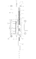
- FIG. 4 is a vertical cross-sectional view taken along the line AA'of FIG.
- FIG. 5 is a side view showing a combination of a set of linear shaft motors and a dispensing head and their upper and lower connecting members extracted from the 8-axis independent control type dispensing device shown in FIG. ..
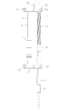
- FIG. 6 is a cross-sectional view showing a part of the internal structure of the linear shaft motor.
- the linear shaft motor 10 is a cylinder (support) made of a non-magnetic material in a state in which a plurality of permanent magnets 12 magnetized in the central axis direction are connected in series with the same magnetic poles facing each other.
- a member) accommodated and fixed in 13 is provided as a first shaft 11.
- the tubular body 13 has a length equal to or greater than the total length of the plurality of permanent magnets 12.
- the tubular body 13 portion accommodating the plurality of permanent magnets 12 may be referred to as a magnet portion for the linear shaft motor 10.
- the linear shaft motor 10 also has a coil portion 15 formed by connecting a plurality of tubular coils 14 in series so as to concentrically include the first shaft 11 via a gap.
- the coil portion 15 is integrated by connecting a plurality of tubular coils 14 in series on the outer peripheral side of the resin coil integrated cylinder 16.
- the coil integrated cylinder 16 has an inner diameter larger than the outer diameter of the cylinder body 13.
- the first shaft 11 and the coil portion 15 are configured to be relatively movable in the central axis direction, but here, the first shaft 11 is configured to be a movable portion and the coil portion 15 is a fixed portion.
- the coil unit 15 is composed of at least three coils 14 of U phase, V phase, and W phase in order to form a three-phase linear motor. Then, an alternating current having a phase difference of 120 degrees is electrically passed through each coil 14, and by controlling the energization of each coil 14, the magnetic field generated from the permanent magnet 12 and the coil 14 are passed. It is configured so that a thrust force for driving the first shaft 11 in the central axis direction can be obtained by the action with the electric current.
- connecting permanent magnets means not only directly connecting the permanent magnets 12 to each other, but also suppressing magnetic characteristics and repulsive force to facilitate assembly, as shown in FIG. In consideration of the manufacturing process, it also includes connecting a soft magnetic material such as soft iron or another permanent magnet magnetized in the radial direction between adjacent permanent magnets 12 as a pole piece.
- a linear motor drive circuit including a power supply, a linear motor control circuit, and the like are well known and are not a main part of the present invention. Therefore, illustration and description of the circuit are omitted, and the position control system will be briefly described later. ..
- a lower connecting member 31 and an upper connecting member 32 are fixed to the lower side and the upper side of the first shaft 11, respectively. Therefore, as the first shaft 11 moves up and down with respect to the coil portion 15 as the fixing portion, the lower connecting member 31 and the upper connecting member 32 also move up and down integrally.
- a dispensing head 40 is attached to the lower connecting member 31 and the upper connecting member 32 in parallel with the central axis of the first shaft 11.
- the dispensing head 40 also has a head body 41 made of a hollow cylindrical body having a length longer than the distance between the lower connecting member 31 and the upper connecting member 32, with reference to FIG. Has a protruding portion 41-1 slightly protruding from the upper connecting member 32 at the upper end portion of the above.
- a nozzle portion 43 having a tip 42 attached to the tip thereof is attached to the lower portion of the head main body 41 protruding from the lower connecting member 31.
- the dispensing head 40 moves up and down integrally with the first shaft 11 via the lower connecting member 31 and the upper connecting member 32.
- the dispensing head 40 has a structure in which a portion above the nozzle portion 43, that is, the head main body 41 is used as a spline axis, and rotation around the central axis thereof is prevented. That is, a spline groove (or a ridge) extending in the central axis direction is provided on the outer periphery of the head body 41 which is the spline axis.
- a ball spline 44 is provided as a fixing portion near the upper side of the lower connecting member 31, and a ridge (or groove) extending in the central axial direction is formed on the inner peripheral side thereof.
- the head body 41 is attached to the ball spline 44 so that the spline groove (or ridge) fits into the ridge (or groove).
- the dispensing head 40 is prevented from falling and dispensed when the dispensing work is off, that is, when the power of the linear shaft motor 10 is turned off.
- a compression spring 45 for holding the head 40 at a predetermined lower limit position is provided.
- a through hole 32a for inserting the first shaft 11 is formed in the upper connecting member 32.
- a slit 32b is formed from the through hole 32a to one end of the upper connecting member 32.
- a hexagon socket head screw 34 which crosses the slit 32b from one side surface side and faces the other side surface side, can be screwed into the one end side of the upper connecting member 32.
- the same fixing structure as above is applied to the lower end side of the first shaft 11. That is, with reference to FIGS. 2 and 5, the lower end of the first shaft 11 inserted into the through hole 31a formed in the lower connecting member 31 is inside the through hole 31a by tightening the hexagon socket head screw 35. Is fixed to. Similar to the upper connecting member 32, the lower connecting member 31 is formed with a slit 31b extending from the through hole 31a to one end of the lower connecting member 31 in order to enable tightening with the hexagon socket head screw 35.
- the 4-axis dispensing device consists of four sets of combinations of the linear shaft motor 10 and the dispensing head 40, and the four linear shaft motors 10 and the four dispensing heads 40 are each of each other. They are combined so that they line up in different parallel planes.
- the coil fixing member 50 is used to arrange the four linear shaft motors 10 in a row.
- the center plate 60 is used to arrange the four dispensing heads 40 in a row.
- the center plate 60 is shared by a pair of 4-axis dispensers when applied to an 8-axis dispenser, also with reference to FIG. Therefore, the center plate 60 has eight accommodation spaces 60a for accommodating the dispensing head 40 of one pair of 4-axis dispensing devices and the dispensing head 40 of the other pair of 4-axis dispensing devices in an alternating manner.
- the ball spline 44 is accommodated in the accommodation space 60a, and a part of the dispensing head 40 equipped with the compression spring 45 is accommodated.
- the ball spline 44 is fixed by a plurality of (here, two) screws 61 screwed from the side wall of the center plate 60 so as not to rotate around the central axis in the accommodation space 60a.
- FIG. 7 shows a screw 61 applied to the ball spline 44 for the dispensing head 40 of one of the pair of 4-axis dispensing devices.
- a screw 62 for fixing a ball spline for the dispensing head 40 of the other 4-axis dispensing device of the pair is screwed into the side wall on the opposite side of the center plate 60.
- the 4-axis dispensing device as shown in FIG. 3 is assembled as follows.
- the 4-axis dispensing device shown in FIG. 3 is, so to speak, a partially omitted view for easy understanding of the explanation, and is not manufactured in the form shown in FIG. This is because the dispensing head 40 is incorporated in the 8-axis dispensing device in a state of being housed in the center plate 60 described with reference to FIGS. 7 and 9.
- a 4-axis dispensing device which is half of the 8-axis dispensing device, is assembled on one side wall side of the center plate 60 shown in FIG. 9, and similarly, 8 on the other side wall side of the center plate 60.
- the other half of the shaft dispenser, the 4-axis dispenser is assembled.
- an 8-axis dispensing device as shown in FIG. 1 is completed. This assembly is. It will be explained later.
- FIG. 10 is a perspective view showing step by step the manufacturing process of the coil unit when the present invention is applied to a 4-axis independent control type dispensing device.
- the coil fixing member 50 is prepared (FIG. 10 (a)).
- the coil fixing member 50 has a receiving portion 51 that can accept four sets of coil portions 15 in a line at a predetermined pitch P1.
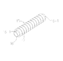
- the coil portion 15 is formed by connecting and fixing a plurality of coils 14 in series to the outer periphery of the resin coil integrated cylinder 16 with reference to FIG. 11.
- the coil integrated cylinder 16 has an inner diameter slightly larger than the outer diameter of the first shaft 11 and a length having protrusions 16-1 protruding from the coils 14 at both ends of the plurality of coils.
- the plurality of coils 14 are arranged as a set of three U-phase-V-phase-W phases, and are delta- or star-connected.
- the receiving portion 51 of the coil fixing member 50 has a bottom wall 51a that defines the bottom surface of the receiving space of the four sets of coil portions 15 arranged side by side in a row, and the receiving space is the center of the coil portion 15. Formed by a pair of wall members 51b facing each other as defined in a direction parallel to the axial direction, and a pair of coil ends 52 provided between the pair of wall members 51b on both ends of the four sets of coil portions 15. Will be done. Both ends of the coil fixing member 50 are recessed in order to secure a connection space with an electric circuit mounted on a circuit board described later.
- the coil end 52 has four through holes 52a into which the protruding portions 16-1 of the coil integrated cylinder 16 protruding from both ends of the four sets of coil portions 15 are inserted, and can be removed by screwing to the bottom wall 51a. Is fixed to. It is desirable that the protruding length of the protruding portion 16-1 is shorter than the plate thickness of the coil end 52, that is, the length of the through hole 52a.
- the coil end 52 is removable from the bottom wall 51a because the total length of the plurality of coils 14 is substantially the same as the distance between the pair of coil ends 52. That is, as shown in FIG. 12, one protruding portion 16-1 of the four sets of coil portions 15 is inserted into the four through holes 52a of the one coil end 52 fixed to the bottom wall 51a of the coil receiving portion 51. After arranging the four sets of coil portions 15 in the receiving portion 51, the other coil end 52 is inserted into the through hole 52a with the other protruding portion 16-1 of the four sets of coil portions 15 inserted into the bottom wall. It is fixed to 51a by screwing.
- the coil ends 52 also have five magnetic shielding plates 70 (FIG. 10 (c)) described later on both sides parallel to the central axis direction of the four sets of coil portions 15 arranged in the receiving portion 51.
- Slit (second slit) 52b is formed.
- the slits 52b are formed on both sides of the through hole 52 in the depth direction from the opening side of the receiving space.
- At least one of the pair of coil ends 52 may be removable from the bottom wall 51a.
- the coils are respectively arranged on both sides of the four sets of coil portions 15 arranged side by side along the central axis direction.
- a magnetic shielding plate 70 longer than the portion 15 is arranged. That is, a total of five magnetic shielding plates 70 are attached to the slits 52b of the pair of coil ends 52, one for each.
- the magnetic shielding plate 70 is for preventing adjacent linear shaft motors from interfering with each other (for example, cogging) due to the adjacent coil portions 15 and the permanent magnets 12 in the first shaft 11.
- the magnetic shielding plate 70 is made of a high magnetic permeability material such as SPCC (cold rolled steel plate) and has a length extending at least over the movable range of a plurality of permanent magnets 12 in the first shaft 11. Further, the width of the magnetic shielding plate 70 is larger than the depth of the receiving space of the receiving portion 51 (diameter of the coil portion 15), and at least the width of the portion corresponding to a part of the receiving space region is defined as the depth of the receiving space. It is about the same. This is because the circuit board 80 can be attached to a portion corresponding to a part of the receiving space region, as will be described later with reference to FIG.
- SPCC cold rolled steel plate
- a curable resin (adhesive) 75 is poured between the coil portion 15 and the magnetic shielding plate 70 in the receiving portion 51 and cured. As a result, the coil portion 15 and the magnetic shielding plate 70 are fixed to the receiving portion 51.
- the magnetic shielding plate 70 may be provided at least at a position corresponding to the adjacent coil portions 15, and the outermost two plates may be omitted. Further, the coil portion 15 and the magnetic shielding plate 70 may be fixed by a fixing method other than the bonding with the curable resin 75.
- FIG. 13 shows an example of the circuit board 80 installed on the opening side of the receiving space in the coil unit manufactured by the manufacturing method of FIG. 10, and FIG. 14 shows the circuit board 80 installed in the receiving portion 51 by screwing. An example of a coil unit is shown.
- the circuit board 80 is installed adjacent to the four sets of linear shaft motors 10 so as to be parallel to their arrangement direction. It is desirable to install the circuit board 80 in the opening of the receiving space as close to the coil unit 15 as possible in consideration of facilitating the connection with the coil unit 15 described later and installing the hall sensor described later. Because.
- the circuit board 80 has a size capable of covering four sets of coil portions 15, in other words, a size capable of covering the opening of the receiving portion 51 of the coil fixing member 50.
- the circuit board 80 also has a notch 81 for exposing a part of the four sets of coil portions 15, and allows the magnetic shielding plate 70 to protrude from the circuit board 80 in a wide portion having a large plate width. It has five slits (first slit) 82.
- the notch 81 is formed to facilitate electrical connection (not shown) between the conductive pattern 84 for coil connection formed on the peripheral edge thereof and the four sets of coil portions 15.
- the slit 82 is formed at a position above the circuit board 80 during operation, even if the magnetic shielding plate 70 is peeled off from the receiving portion 51 due to poor adhesion, the lower end portion of the wide portion is slit. By being caught on the lower end edge of the 82, the magnetic shielding plate 70 is prevented from falling to the microplate.
- 83 is a pair of magnetic sensors for detecting the position of the permanent magnet 12 in the first shaft 11, here, an analog hole sensor (hereinafter, abbreviated as a hole sensor).
- the pair of Hall sensors 83 are used for position control of the first shaft 11 in the linear shaft motor 10.
- the pair of Hall sensors 83 are installed at positions corresponding to the first shaft 11 and adjacent to the wide portion of the magnetic shielding plate 70 at predetermined mounting intervals in the moving direction of the first shaft 11. As shown in FIG. 18, the mounting interval of the pair of Hall sensors 83 is set to an electric angle of 90 degrees of the waveform of the surface magnetic flux density of the first shaft 11 (permanent magnet 12).
- the surface magnetic flux density of the first shaft 11 (permanent magnet 12) is that of the first shaft 11. It is based on the finding that the waveform becomes close to a sine wave as it moves away from the surface to some extent.
- ⁇ NN indicates the magnetic pole pitch of the permanent magnet 12
- D indicates the diameter of the first shaft 11
- B 0 indicates the peak value of the surface magnetic flux density of the first shaft 11.
- the position where the data closer to the sine wave can be obtained is determined as the installation location of the hall sensor 83 while referring to the measurement data as shown in FIG.
- the pair of Hall sensors 83 is provided on the surface side of the circuit board 80 (the surface on the receiving portion 51 side, that is, the surface opposite to the coil portion 15 side), and the two magnets are used. It is installed between the wide portions of the shielding plate 70. That is, by forming the slit 82 in the circuit board 80, the wide portion of the magnetic shielding plate 70 is extended into the receiving portion 51 of the coil fixing member 50. This is to prevent the influence of the magnetic field from the linear shaft motor 10 adjacent to the pair of Hall sensors 83 installed between the large plate width portions of the two magnetic shielding plates 70. be.
- the electric circuit mounted on the circuit board 80 is mainly a circuit for driving and controlling four linear shaft motors 10 connected to a plurality of coils 14, but the description of the circuit is omitted and is shown in FIG.
- the position control system of the linear shaft motor 10 will be described with reference to 20.
- FIG. 20 is a block diagram of the position control system of the linear shaft motor 10, and this position control system is installed in the linear shaft motor 10 of each axis.
- the microcomputer 88 can be common to the linear shaft motors 10 of all shafts.
- This position control system digitizes the signals from the two Hall sensors 83 installed on the circuit board 80, the operational amplifier 85 that processes the detection signals from the two Hall sensors 83, and the operational amplifier 85.
- the linear shaft motor 10 with respect to the interpolator 86, the motor drive circuit 87 that drives and controls the first shaft 11 of the linear shaft motor 10 based on the digital signal from the interpolator 86, and the motor drive circuit 87.
- This position control system generates a negative voltage signal in addition to a positive voltage signal from the detection signals of the two Hall sensors 83 (when there is signal inversion) and a positive voltage signal from the detection signals of the two Hall sensors 83.
- FIG. 20 shows a case without signal inversion, but in the case with signal inversion, the number of output signal lines after the operational amplifier 85 is different.
- the surface magnetic flux density of the first shaft 11 is detected by the Hall sensor 83 and output as an analog voltage signal.
- the surface magnetic flux density of the first shaft 11 is a sinusoidal wave along the axial direction. Therefore, when two Hall sensors 83 are arranged near the first shaft 11 at 1/4 of the magnetic pole pitch of the permanent magnet 12 (hereinafter referred to as magnet pitch) and the magnetic flux density is detected, the electric angle is 90 degrees. It is possible to generate two out-of-phase analog voltage signals, that is, a sine wave (hereinafter, Sin wave) voltage signal and a cosine wave (hereinafter, Cos wave) voltage signal.
- Sin wave sine wave
- Cos wave cosine wave
- the analog voltage signals output from the two Hall sensors 83 are input to the operational amplifier 85.
- the operational amplifier 85 adjusts the output voltages of the two Hall sensors 83 to match the driver inputs.
- the driver interpolator 86 digitizes the two analog signals input from the operational amplifier 85 and divides them by a specified number of bits.
- the division number defines the resolution (magnet pitch / number of divisions), for example, the magnet pitch 24 mm, if the number of divisions 2 14, the resolution is 1.5 [mu] m.
- the two analog voltage signals (Sin wave voltage signal and Cos wave voltage signal) become two square wave signals (position signals) that are 90 degrees out of phase with each other in terms of electrical angle.
- the motor drive circuit 87 detects the current position and moving speed of the first shaft 11 (dispensing head 40) from the two square wave signals input from the interpolator 86, and causes the linear shaft motor 10 (coil portion 15) to detect the current position and moving speed. Issue a position control command that defines the stop position.
- the surface magnetic flux density of the first shaft 11 is detected by the two Hall sensors 83 and output as an analog voltage signal.
- the surface magnetic flux density of the first shaft 11 is a sinusoidal wave along the axial direction.
- magnet pitch 1/4 of the magnetic pole pitch of the permanent magnet 12
- the phase is 90 degrees in electrical angle. It is possible to generate two staggered analog voltage signals, that is, a sine wave voltage signal and a Cos wave voltage signal.
- the two analog voltage signals output from the two Hall sensors 83 are input to the operational amplifier 85.
- the operational amplifier 85 generates an inverting signal for each of the two input analog voltage signals (sine wave voltage signal and Cos wave voltage signal).
- the -Sin wave voltage signal and the -Cos wave voltage signal are generated to become four analog voltage signals.
- the operational amplifier 85 also adjusts the output voltage of the Hall sensor 83 to match the driver input.
- only two signals, a sine wave voltage signal and a Cos wave voltage signal may be used, but by generating a -Sin wave voltage signal and a -Cos wave voltage signal, the signal becomes resistant to noise.
- the driver interpolator 86 digitizes the four analog voltage signals output from the operational amplifier 85 and divides them by a specified number of bits. The resolution represented by the magnet pitch and the number of divisions is as described above. As a result, the four analog voltage signals become four square wave signals (position signals).
- the motor drive circuit 87 detects the current position and moving speed of the first shaft 10 (dispensing head 40) from the four square wave signals (position signals) output from the interpolator 86, and detects the linear shaft motor 11 (positional signal). A position control command that defines the stop position is issued to the coil unit 15).
- the 8-axis independent control type dispensing device is manufactured by assembling the 4-axis independent control type dispensing device described with reference to FIG. 3 using the coil unit manufactured by the above manufacturing method. Subsequently, a pair of 4-axis independent control type dispensing devices are arranged so that the circuit boards 80 face each other via the center plate 60, and the dispensing device and the center plate 60 are connected at both ends in the longitudinal direction. Combine so that they are more integrated with 90.
- the connecting plate 90 has an E-shape having recesses corresponding to recesses formed at both ends of the coil fixing member 50 on both sides.
- the connecting plate 90 is attached to the longitudinal end face of the pair of coil fixing members 50 and the longitudinal end face of the center plate 60 by hexagon socket head screws 91 at two locations, respectively.
- hexagon socket head screws 91 at two locations, respectively.
- the linear shaft motor 10, the dispensing head 40, the lower connecting member 31, the upper connecting member 32, etc. in the 4-axis independent control type dispensing device described with reference to FIG. 5 are not shown. doing.
- a pair of 4-axis independent control type dispensers The dispensing device and the center plate 60 are integrated by two connecting plates 90 on both end sides thereof to form an 8-axis independent control type dispensing device as shown in FIG.
- the pitch (interval) of the linear shaft motors 10 is P1, as shown in FIG.
- the four dispensing heads 40 in one dispensing device and the four dispensing heads 40 in the other dispensing device are center plates. It is integrated in a state of being alternately accommodated in eight accommodation spaces 60a of 60.
- the pitch (interval) P2 of the eight dispensing heads 40 is small, the pitch (interval) P1 of the linear shaft motor 10 can be increased. It is possible to prevent malfunction due to magnetic field interference between adjacent linear shaft motors 10 without reducing the size of the permanent magnet 12 or the coil 14.
- the 8-axis independent control type dispensing device is assembled to a transport mechanism (not shown) for reciprocating between the suction position and the discharge position of the liquid. Therefore, the connecting plate 90 may be omitted by fixing the pair of coil fixing members 50 and the center plate 60 to a part of the transport mechanism.
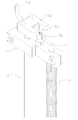
- FIG. 16 is a perspective view for explaining the detector 100 that detects the upward movement position of the upper connecting member 32 in the 8-axis independent control type dispensing device shown in FIG. 17A and 17B are views for explaining an example of the installation form of the detector 100 shown in FIG. 16, in which FIG. 17A is a side view of an 8-axis independent control type dispensing device, and FIG. 17B is a side view. It is a perspective view of the 8-axis independent control type dispensing device.
- the upper moving position of the upper connecting member 32 is detected as the upper limit position, so that the dispensing heads 40 of the same set
- the upward movement position is detected.
- a hollow shaft-shaped protrusion 101 to be detected is provided on the upper end surface near the center thereof.
- a photo sensor 102 is provided as a limit sensor so that light is blocked when the protrusion 101 to be detected moves upward to a predetermined position. As shown in FIGS.
- the photosensor 102 is a sensor installation substrate via a support column 110 fixed to the center plate 60 at a position higher than the upward movement position of the upper connecting member 32.
- the 111 is fixedly arranged, and eight photosensors 102 are installed on the sensor installation board 111 so as to correspond to the eight detected protrusions 101 of the 8-axis independent control type.
- the sensor installation board 111 photosensor 102 is paired. Together with the coil fixing member 50 and the center plate 60 of the above, it becomes a fixing portion.
- the detector 100 is used not only as a means for detecting the upward movement position of the dispensing head 40 accompanying the dispensing work of sucking and discharging the liquid, but also as a means for positioning the origin when starting the dispensing work. Will be done. Origin positioning is as follows.
- the protrusion 101 to be detected blocks the optical path of the photo sensor 102, and each dispensing head 40 is moved upward until a detection signal is output from the photo sensor 102.
- the offset operation is performed with reference to the detection signal output from the photo sensor 102. Since the offset position has the same height for each axis, this position is used as a reference point for positioning control of the linear shaft motor 10 described later.
- a cable 103 for signal transmission extends from one end side of the photo sensor 102, but for convenience, only a part of the cable 103 is cut and shown.
- a position detecting means for controlling the position of the linear shaft motor of each axis in the dispensing device can be realized at low cost, and as a result, as a result. It is possible to provide an 8-axis independent control type dispensing device that is effective in reducing costs.
- the pitch (interval) P1 of the linear shaft motor 10 does not need to be reduced, so that the size of the permanent magnet 12 and the coil 14 can be reduced accordingly.
- the dispensing device can be configured without the need for. This is effective from the following viewpoints.
- a multi-axis type dispensing device it is required to reduce the pitch (interval) between the dispensing heads. This is because by reducing the pitch between the dispensing heads, the entire multi-axis dispensing device can be made compact and the movable range can be increased.
- the diameter of the linear shaft motor must be reduced in order to reduce the pitch between the dispensing heads.
- the diameter of the permanent magnet must be reduced, or the diameter of the coil, that is, the number of turns of the coil must be reduced. This means that the thrust (driving torque) of each axis becomes small.
- a predetermined thrust is required for the vertical movement of the dispensing head.
- the tip 42 attached to the tip of the nozzle 43 is removed by jigging the constricted portion between the tip 42 and the nozzle 43 at a place other than the place where the liquid is sucked and discharged. This is because automation is performed by moving the head body 41 upward while being sandwiched between (not shown). In other words, when the thrust of the vertical movement of the dispensing head becomes small, it becomes difficult to automatically remove the tip 42.
- the pitch between the dispensing heads is reduced and the diameter of the linear shaft motor is not reduced. Note: Since a predetermined thrust (driving torque) can be obtained when the head moves up and down, the above problems do not occur.
- the coil portion of the linear shaft motor is housed in the casing for each coil portion.
- a plurality of first shafts 11 are arranged adjacent to each other, a plurality of sets of coil portions 15 can be unitized together, so that the number of parts in the coil unit can be reduced and the number of assembly steps can be reduced. Reduction and space saving can be realized.
- magnetic shielding plates 70 may be installed on both sides along the central axis direction of each coil portion 15, and the coil portions 15 and the magnetic shielding plates 70 may be fixed at the same time by the curable resin 75. From this point as well, it is possible to reduce the number of parts in the coil unit, reduce the number of assembly steps, and save space.
- the present invention is not limited to the above embodiment. That is, the present invention can be applied to both an independent control type and a simultaneous control type as long as it is a multi-axis dispenser having two or more axes, and further, the present invention is not limited to the dispenser and is a multi-axis linear motor. It can be applied to all actuators.
- the present invention also relates to a multi-axis type linear motor actuator in which a linear shaft motor is configured as an independent unit for each axis and arranged in a row in a plurality of sets at a predetermined pitch (furthermore, a multi-axis combined with a dispensing head).
- a linear shaft motor is configured as an independent unit for each axis and arranged in a row in a plurality of sets at a predetermined pitch (furthermore, a multi-axis combined with a dispensing head).
- the circuit board with a slit described above, a magnetic shielding plate having a wide portion, and a hall sensor can be applied in combination in another manner as described below without the coil fixing member described above. can do.
- Circuit board and It has a size capable of covering a plurality of coil portions in the plurality of sets of linear shaft motors arranged in a row, and is combined so as to be adjacent to the plurality of sets of linear shaft motors and parallel to the arrangement direction thereof.
- Circuit board and It has a plurality of magnetic shielding plates longer than the coil portions, which are arranged and fixed along the axial direction at positions corresponding to at least adjacent coil portions of the plurality of coil portions arranged in the same row.
- a pair of Hall sensors are installed in the regions of the circuit board corresponding to the same number of the plurality of shafts as the plurality of sets at intervals in the moving direction of the shafts.
- the width corresponding to at least the area where the pair of hall sensors are installed in the magnetic shielding plate is set to be a wide portion larger than the depth of the receiving space.
- a plurality of first slits for inserting the wide portion are formed in the circuit board.
Landscapes
- Engineering & Computer Science (AREA)
- Power Engineering (AREA)
- Physics & Mathematics (AREA)
- Electromagnetism (AREA)
- Chemical & Material Sciences (AREA)
- Combustion & Propulsion (AREA)
- Microelectronics & Electronic Packaging (AREA)
- Linear Motors (AREA)
Priority Applications (1)
| Application Number | Priority Date | Filing Date | Title |
|---|---|---|---|
| US17/918,819 US12003159B2 (en) | 2020-04-24 | 2021-02-05 | Multi-axis linear motor actuator |
Applications Claiming Priority (2)
| Application Number | Priority Date | Filing Date | Title |
|---|---|---|---|
| JP2020077351A JP7437027B2 (ja) | 2020-04-24 | 2020-04-24 | 多軸リニアモータアクチュエータ |
| JP2020-077351 | 2020-04-24 |
Publications (1)
| Publication Number | Publication Date |
|---|---|
| WO2021215075A1 true WO2021215075A1 (ja) | 2021-10-28 |
Family
ID=78269408
Family Applications (1)
| Application Number | Title | Priority Date | Filing Date |
|---|---|---|---|
| PCT/JP2021/004284 Ceased WO2021215075A1 (ja) | 2020-04-24 | 2021-02-05 | 多軸リニアモータアクチュエータ |
Country Status (3)
| Country | Link |
|---|---|
| US (1) | US12003159B2 (https=) |
| JP (1) | JP7437027B2 (https=) |
| WO (1) | WO2021215075A1 (https=) |
Families Citing this family (2)
| Publication number | Priority date | Publication date | Assignee | Title |
|---|---|---|---|---|
| JP7437686B2 (ja) * | 2020-04-24 | 2024-02-26 | 日本パルスモーター株式会社 | 多軸リニアモータアクチュエータにおけるコイルユニット及びその製造方法 |
| JP7154665B1 (ja) | 2022-03-31 | 2022-10-18 | 北日本通信工業株式会社 | 景品取得装置及び景品取得ゲーム装置 |
Citations (3)
| Publication number | Priority date | Publication date | Assignee | Title |
|---|---|---|---|---|
| JPH07163128A (ja) * | 1993-12-03 | 1995-06-23 | Nippon Thompson Co Ltd | 2以上の可動テーブルを有する直流リニアモータ |
| JP2006180645A (ja) * | 2004-12-24 | 2006-07-06 | Matsushita Electric Ind Co Ltd | 多軸リニアモータ、及び該多軸リニアモータを利用する実装ヘッド、部品実装装置、並びに磁力遮蔽材及び磁力遮蔽方法 |
| JP6651142B2 (ja) * | 2015-10-06 | 2020-02-19 | 日本パルスモーター株式会社 | リニアモータのシャフト、およびその製造方法 |
Family Cites Families (5)
| Publication number | Priority date | Publication date | Assignee | Title |
|---|---|---|---|---|
| JP5013264B2 (ja) | 2007-11-05 | 2012-08-29 | 日本パルスモーター株式会社 | 出力軸を備えたカム装置 |
| JP4705118B2 (ja) * | 2008-01-11 | 2011-06-22 | ヤマハ発動機株式会社 | 多軸リニアモータ及び部品移載装置 |
| JP5483200B2 (ja) | 2010-10-22 | 2014-05-07 | 株式会社安川電機 | リニアモータ |
| JP6166926B2 (ja) * | 2013-03-26 | 2017-07-19 | 山洋電気株式会社 | リニアモータ |
| JP6710055B2 (ja) | 2016-02-02 | 2020-06-17 | 株式会社ジイエムシーヒルストン | スケール一体型リニアモータ及びこれを備えた直動ユニット |
-
2020
- 2020-04-24 JP JP2020077351A patent/JP7437027B2/ja active Active
-
2021
- 2021-02-05 WO PCT/JP2021/004284 patent/WO2021215075A1/ja not_active Ceased
- 2021-02-05 US US17/918,819 patent/US12003159B2/en active Active
Patent Citations (3)
| Publication number | Priority date | Publication date | Assignee | Title |
|---|---|---|---|---|
| JPH07163128A (ja) * | 1993-12-03 | 1995-06-23 | Nippon Thompson Co Ltd | 2以上の可動テーブルを有する直流リニアモータ |
| JP2006180645A (ja) * | 2004-12-24 | 2006-07-06 | Matsushita Electric Ind Co Ltd | 多軸リニアモータ、及び該多軸リニアモータを利用する実装ヘッド、部品実装装置、並びに磁力遮蔽材及び磁力遮蔽方法 |
| JP6651142B2 (ja) * | 2015-10-06 | 2020-02-19 | 日本パルスモーター株式会社 | リニアモータのシャフト、およびその製造方法 |
Also Published As
| Publication number | Publication date |
|---|---|
| US20230155469A1 (en) | 2023-05-18 |
| US12003159B2 (en) | 2024-06-04 |
| JP2021175266A (ja) | 2021-11-01 |
| JP7437027B2 (ja) | 2024-02-22 |
Similar Documents
| Publication | Publication Date | Title |
|---|---|---|
| CN102171914B (zh) | 直线-旋转复合致动器 | |
| CN1266479C (zh) | 产生旋转速度相关信号的装置和电子整流直流电动机 | |
| US10312839B2 (en) | Brushless DC motor with control electronics motor assembly | |
| US20100289442A1 (en) | Brushless motor position detection device | |
| CN101444151B (zh) | 用于印刷电路板的插入机的给料器装置 | |
| WO2021215075A1 (ja) | 多軸リニアモータアクチュエータ | |
| JP2004112864A (ja) | リニアモータを内蔵したxyステージ装置 | |
| US10396643B2 (en) | Motor | |
| US20210336499A1 (en) | Electric motor and method for manufacturing electric motor | |
| US20100052457A1 (en) | Methods and apparatus for fabrication of electric motors | |
| CN1815860A (zh) | 带编码器的小型电动机 | |
| JP7437686B2 (ja) | 多軸リニアモータアクチュエータにおけるコイルユニット及びその製造方法 | |
| JP7645577B2 (ja) | 多軸リニアモータアクチュエータ | |
| US20210281198A1 (en) | Motor | |
| KR102472116B1 (ko) | 피시험모터의 코깅토크 또는 역기전력 측정이 가능한 무부하 시험장치 및 이를 이용한 무부하 시험방법 | |
| CN116097554A (zh) | 旋转工作台装置 | |
| WO2022264204A1 (ja) | 磁気式ロータリーエンコーダ | |
| CN1324790C (zh) | 永久磁铁型电动机的磁化方法及装置 | |
| JP7416418B2 (ja) | 多軸アクチュエータ | |
| CN224163205U (zh) | 校准装置、系统、分体式编码器和电机 | |
| CN104040846A (zh) | 用于驱动发动机的控制模块 | |
| JP2000116175A (ja) | ブラシレスモータ | |
| US20250341597A1 (en) | Magnetic compensation circuit for linear hall sensors | |
| JP2004120933A (ja) | ブラシレスモータ | |
| JP2007244029A (ja) | モータシャフト及びその製造装置 |
Legal Events
| Date | Code | Title | Description |
|---|---|---|---|
| 121 | Ep: the epo has been informed by wipo that ep was designated in this application |
Ref document number: 21791739 Country of ref document: EP Kind code of ref document: A1 |
|
| NENP | Non-entry into the national phase |
Ref country code: DE |
|
| 122 | Ep: pct application non-entry in european phase |
Ref document number: 21791739 Country of ref document: EP Kind code of ref document: A1 |