WO2021214832A1 - 冷凍サイクル装置 - Google Patents
冷凍サイクル装置 Download PDFInfo
- Publication number
- WO2021214832A1 WO2021214832A1 PCT/JP2020/017058 JP2020017058W WO2021214832A1 WO 2021214832 A1 WO2021214832 A1 WO 2021214832A1 JP 2020017058 W JP2020017058 W JP 2020017058W WO 2021214832 A1 WO2021214832 A1 WO 2021214832A1
- Authority
- WO
- WIPO (PCT)
- Prior art keywords
- heat exchange
- exchange section
- refrigerant
- section
- region
- Prior art date
Links
Images


Classifications
-
- F—MECHANICAL ENGINEERING; LIGHTING; HEATING; WEAPONS; BLASTING
- F28—HEAT EXCHANGE IN GENERAL
- F28D—HEAT-EXCHANGE APPARATUS, NOT PROVIDED FOR IN ANOTHER SUBCLASS, IN WHICH THE HEAT-EXCHANGE MEDIA DO NOT COME INTO DIRECT CONTACT
- F28D1/00—Heat-exchange apparatus having stationary conduit assemblies for one heat-exchange medium only, the media being in contact with different sides of the conduit wall, in which the other heat-exchange medium is a large body of fluid, e.g. domestic or motor car radiators
- F28D1/02—Heat-exchange apparatus having stationary conduit assemblies for one heat-exchange medium only, the media being in contact with different sides of the conduit wall, in which the other heat-exchange medium is a large body of fluid, e.g. domestic or motor car radiators with heat-exchange conduits immersed in the body of fluid
- F28D1/04—Heat-exchange apparatus having stationary conduit assemblies for one heat-exchange medium only, the media being in contact with different sides of the conduit wall, in which the other heat-exchange medium is a large body of fluid, e.g. domestic or motor car radiators with heat-exchange conduits immersed in the body of fluid with tubular conduits
- F28D1/047—Heat-exchange apparatus having stationary conduit assemblies for one heat-exchange medium only, the media being in contact with different sides of the conduit wall, in which the other heat-exchange medium is a large body of fluid, e.g. domestic or motor car radiators with heat-exchange conduits immersed in the body of fluid with tubular conduits the conduits being bent, e.g. in a serpentine or zig-zag
- F28D1/0477—Heat-exchange apparatus having stationary conduit assemblies for one heat-exchange medium only, the media being in contact with different sides of the conduit wall, in which the other heat-exchange medium is a large body of fluid, e.g. domestic or motor car radiators with heat-exchange conduits immersed in the body of fluid with tubular conduits the conduits being bent, e.g. in a serpentine or zig-zag the conduits being bent in a serpentine or zig-zag
-
- F—MECHANICAL ENGINEERING; LIGHTING; HEATING; WEAPONS; BLASTING
- F25—REFRIGERATION OR COOLING; COMBINED HEATING AND REFRIGERATION SYSTEMS; HEAT PUMP SYSTEMS; MANUFACTURE OR STORAGE OF ICE; LIQUEFACTION SOLIDIFICATION OF GASES
- F25B—REFRIGERATION MACHINES, PLANTS OR SYSTEMS; COMBINED HEATING AND REFRIGERATION SYSTEMS; HEAT PUMP SYSTEMS
- F25B41/00—Fluid-circulation arrangements
- F25B41/20—Disposition of valves, e.g. of on-off valves or flow control valves
-
- F—MECHANICAL ENGINEERING; LIGHTING; HEATING; WEAPONS; BLASTING
- F24—HEATING; RANGES; VENTILATING
- F24F—AIR-CONDITIONING; AIR-HUMIDIFICATION; VENTILATION; USE OF AIR CURRENTS FOR SCREENING
- F24F1/00—Room units for air-conditioning, e.g. separate or self-contained units or units receiving primary air from a central station
- F24F1/06—Separate outdoor units, e.g. outdoor unit to be linked to a separate room comprising a compressor and a heat exchanger
- F24F1/38—Fan details of outdoor units, e.g. bell-mouth shaped inlets or fan mountings
-
- F—MECHANICAL ENGINEERING; LIGHTING; HEATING; WEAPONS; BLASTING
- F25—REFRIGERATION OR COOLING; COMBINED HEATING AND REFRIGERATION SYSTEMS; HEAT PUMP SYSTEMS; MANUFACTURE OR STORAGE OF ICE; LIQUEFACTION SOLIDIFICATION OF GASES
- F25B—REFRIGERATION MACHINES, PLANTS OR SYSTEMS; COMBINED HEATING AND REFRIGERATION SYSTEMS; HEAT PUMP SYSTEMS
- F25B39/00—Evaporators; Condensers
- F25B39/02—Evaporators
-
- F—MECHANICAL ENGINEERING; LIGHTING; HEATING; WEAPONS; BLASTING
- F25—REFRIGERATION OR COOLING; COMBINED HEATING AND REFRIGERATION SYSTEMS; HEAT PUMP SYSTEMS; MANUFACTURE OR STORAGE OF ICE; LIQUEFACTION SOLIDIFICATION OF GASES
- F25B—REFRIGERATION MACHINES, PLANTS OR SYSTEMS; COMBINED HEATING AND REFRIGERATION SYSTEMS; HEAT PUMP SYSTEMS
- F25B39/00—Evaporators; Condensers
- F25B39/04—Condensers
-
- F—MECHANICAL ENGINEERING; LIGHTING; HEATING; WEAPONS; BLASTING
- F25—REFRIGERATION OR COOLING; COMBINED HEATING AND REFRIGERATION SYSTEMS; HEAT PUMP SYSTEMS; MANUFACTURE OR STORAGE OF ICE; LIQUEFACTION SOLIDIFICATION OF GASES
- F25B—REFRIGERATION MACHINES, PLANTS OR SYSTEMS; COMBINED HEATING AND REFRIGERATION SYSTEMS; HEAT PUMP SYSTEMS
- F25B40/00—Subcoolers, desuperheaters or superheaters
- F25B40/02—Subcoolers
-
- F—MECHANICAL ENGINEERING; LIGHTING; HEATING; WEAPONS; BLASTING
- F28—HEAT EXCHANGE IN GENERAL
- F28D—HEAT-EXCHANGE APPARATUS, NOT PROVIDED FOR IN ANOTHER SUBCLASS, IN WHICH THE HEAT-EXCHANGE MEDIA DO NOT COME INTO DIRECT CONTACT
- F28D1/00—Heat-exchange apparatus having stationary conduit assemblies for one heat-exchange medium only, the media being in contact with different sides of the conduit wall, in which the other heat-exchange medium is a large body of fluid, e.g. domestic or motor car radiators
- F28D1/02—Heat-exchange apparatus having stationary conduit assemblies for one heat-exchange medium only, the media being in contact with different sides of the conduit wall, in which the other heat-exchange medium is a large body of fluid, e.g. domestic or motor car radiators with heat-exchange conduits immersed in the body of fluid
- F28D1/04—Heat-exchange apparatus having stationary conduit assemblies for one heat-exchange medium only, the media being in contact with different sides of the conduit wall, in which the other heat-exchange medium is a large body of fluid, e.g. domestic or motor car radiators with heat-exchange conduits immersed in the body of fluid with tubular conduits
- F28D1/0408—Multi-circuit heat exchangers, e.g. integrating different heat exchange sections in the same unit or heat exchangers for more than two fluids
- F28D1/0417—Multi-circuit heat exchangers, e.g. integrating different heat exchange sections in the same unit or heat exchangers for more than two fluids with particular circuits for the same heat exchange medium, e.g. with the heat exchange medium flowing through sections having different heat exchange capacities or for heating/cooling the heat exchange medium at different temperatures
-
- F—MECHANICAL ENGINEERING; LIGHTING; HEATING; WEAPONS; BLASTING
- F28—HEAT EXCHANGE IN GENERAL
- F28D—HEAT-EXCHANGE APPARATUS, NOT PROVIDED FOR IN ANOTHER SUBCLASS, IN WHICH THE HEAT-EXCHANGE MEDIA DO NOT COME INTO DIRECT CONTACT
- F28D1/00—Heat-exchange apparatus having stationary conduit assemblies for one heat-exchange medium only, the media being in contact with different sides of the conduit wall, in which the other heat-exchange medium is a large body of fluid, e.g. domestic or motor car radiators
- F28D1/02—Heat-exchange apparatus having stationary conduit assemblies for one heat-exchange medium only, the media being in contact with different sides of the conduit wall, in which the other heat-exchange medium is a large body of fluid, e.g. domestic or motor car radiators with heat-exchange conduits immersed in the body of fluid
- F28D1/04—Heat-exchange apparatus having stationary conduit assemblies for one heat-exchange medium only, the media being in contact with different sides of the conduit wall, in which the other heat-exchange medium is a large body of fluid, e.g. domestic or motor car radiators with heat-exchange conduits immersed in the body of fluid with tubular conduits
- F28D1/0408—Multi-circuit heat exchangers, e.g. integrating different heat exchange sections in the same unit or heat exchangers for more than two fluids
- F28D1/0426—Multi-circuit heat exchangers, e.g. integrating different heat exchange sections in the same unit or heat exchangers for more than two fluids with units having particular arrangement relative to the large body of fluid, e.g. with interleaved units or with adjacent heat exchange units in common air flow or with units extending at an angle to each other or with units arranged around a central element
- F28D1/0435—Combination of units extending one behind the other
-
- F—MECHANICAL ENGINEERING; LIGHTING; HEATING; WEAPONS; BLASTING
- F28—HEAT EXCHANGE IN GENERAL
- F28D—HEAT-EXCHANGE APPARATUS, NOT PROVIDED FOR IN ANOTHER SUBCLASS, IN WHICH THE HEAT-EXCHANGE MEDIA DO NOT COME INTO DIRECT CONTACT
- F28D1/00—Heat-exchange apparatus having stationary conduit assemblies for one heat-exchange medium only, the media being in contact with different sides of the conduit wall, in which the other heat-exchange medium is a large body of fluid, e.g. domestic or motor car radiators
- F28D1/02—Heat-exchange apparatus having stationary conduit assemblies for one heat-exchange medium only, the media being in contact with different sides of the conduit wall, in which the other heat-exchange medium is a large body of fluid, e.g. domestic or motor car radiators with heat-exchange conduits immersed in the body of fluid
- F28D1/04—Heat-exchange apparatus having stationary conduit assemblies for one heat-exchange medium only, the media being in contact with different sides of the conduit wall, in which the other heat-exchange medium is a large body of fluid, e.g. domestic or motor car radiators with heat-exchange conduits immersed in the body of fluid with tubular conduits
- F28D1/0408—Multi-circuit heat exchangers, e.g. integrating different heat exchange sections in the same unit or heat exchangers for more than two fluids
- F28D1/0426—Multi-circuit heat exchangers, e.g. integrating different heat exchange sections in the same unit or heat exchangers for more than two fluids with units having particular arrangement relative to the large body of fluid, e.g. with interleaved units or with adjacent heat exchange units in common air flow or with units extending at an angle to each other or with units arranged around a central element
- F28D1/0452—Combination of units extending one behind the other with units extending one beside or one above the other
-
- F—MECHANICAL ENGINEERING; LIGHTING; HEATING; WEAPONS; BLASTING
- F28—HEAT EXCHANGE IN GENERAL
- F28F—DETAILS OF HEAT-EXCHANGE AND HEAT-TRANSFER APPARATUS, OF GENERAL APPLICATION
- F28F1/00—Tubular elements; Assemblies of tubular elements
- F28F1/10—Tubular elements and assemblies thereof with means for increasing heat-transfer area, e.g. with fins, with projections, with recesses
- F28F1/12—Tubular elements and assemblies thereof with means for increasing heat-transfer area, e.g. with fins, with projections, with recesses the means being only outside the tubular element
- F28F1/24—Tubular elements and assemblies thereof with means for increasing heat-transfer area, e.g. with fins, with projections, with recesses the means being only outside the tubular element and extending transversely
- F28F1/32—Tubular elements and assemblies thereof with means for increasing heat-transfer area, e.g. with fins, with projections, with recesses the means being only outside the tubular element and extending transversely the means having portions engaging further tubular elements
- F28F1/325—Fins with openings
-
- F—MECHANICAL ENGINEERING; LIGHTING; HEATING; WEAPONS; BLASTING
- F24—HEATING; RANGES; VENTILATING
- F24F—AIR-CONDITIONING; AIR-HUMIDIFICATION; VENTILATION; USE OF AIR CURRENTS FOR SCREENING
- F24F1/00—Room units for air-conditioning, e.g. separate or self-contained units or units receiving primary air from a central station
- F24F1/06—Separate outdoor units, e.g. outdoor unit to be linked to a separate room comprising a compressor and a heat exchanger
- F24F1/14—Heat exchangers specially adapted for separate outdoor units
-
- F—MECHANICAL ENGINEERING; LIGHTING; HEATING; WEAPONS; BLASTING
- F25—REFRIGERATION OR COOLING; COMBINED HEATING AND REFRIGERATION SYSTEMS; HEAT PUMP SYSTEMS; MANUFACTURE OR STORAGE OF ICE; LIQUEFACTION SOLIDIFICATION OF GASES
- F25B—REFRIGERATION MACHINES, PLANTS OR SYSTEMS; COMBINED HEATING AND REFRIGERATION SYSTEMS; HEAT PUMP SYSTEMS
- F25B13/00—Compression machines, plants or systems, with reversible cycle
-
- F—MECHANICAL ENGINEERING; LIGHTING; HEATING; WEAPONS; BLASTING
- F28—HEAT EXCHANGE IN GENERAL
- F28D—HEAT-EXCHANGE APPARATUS, NOT PROVIDED FOR IN ANOTHER SUBCLASS, IN WHICH THE HEAT-EXCHANGE MEDIA DO NOT COME INTO DIRECT CONTACT
- F28D21/00—Heat-exchange apparatus not covered by any of the groups F28D1/00 - F28D20/00
- F28D2021/0019—Other heat exchangers for particular applications; Heat exchange systems not otherwise provided for
- F28D2021/0068—Other heat exchangers for particular applications; Heat exchange systems not otherwise provided for for refrigerant cycles
Definitions
- the compressor 1, the four-way valve 2, the outdoor heat exchanger 3, the pressure reducing valve 4, the control device CD, and the blower device 6 are housed in the outdoor unit 101.
- the indoor heat exchanger 5 and the blower 7 are housed in the indoor unit 102.
- the refrigerant circulates in the order of the compressor 1, the four-way valve 2, the outdoor heat exchanger (condenser) 3, the pressure reducing valve 4, the indoor heat exchanger (evaporator) 5, and the four-way valve 2 during the cooling operation. It is configured as follows. Further, in the refrigerant circuit RC, during the heating operation, the refrigerant is supplied in the order of the compressor 1, the four-way valve 2, the indoor heat exchanger (condenser) 5, the pressure reducing valve 4, the outdoor heat exchanger (evaporator) 3, and the four-way valve 2. It is configured to circulate.
- the refrigerant is a non-azeotropic mixed refrigerant having a temperature gradient in which the temperature of the refrigerant decreases as the dryness of the refrigerant decreases.
- the refrigerant include R407C and R454A.
- the control device CD is configured to control each device of the refrigeration cycle device 100 by performing calculations, instructions, and the like.
- the control device CD is electrically connected to a compressor 1, a four-way valve 2, a pressure reducing valve 4, a blower device 6, 7, and the like, and is configured to control the operation of these.
- the compressor 1 is configured to compress the refrigerant.
- the compressor 1 is configured to compress and discharge the sucked refrigerant.
- the compressor 1 may be configured to have a variable capacity.
- the compressor 1 may be configured so that the capacity is changed by adjusting the rotation speed of the compressor 1 based on an instruction from the control device CD.
- the four-way valve 2 is configured to switch the flow of the refrigerant so that the refrigerant compressed by the compressor 1 flows to the outdoor heat exchanger 3 or the indoor heat exchanger 5.
- the four-way valve 2 is configured to allow the refrigerant discharged from the compressor 1 to flow to the outdoor heat exchanger (condenser) 3 during the cooling operation. Further, the four-way valve 2 is configured to allow the refrigerant discharged from the compressor 1 to flow to the indoor heat exchanger (evaporator) 5 during the heating operation.
- the outdoor heat exchanger 3 is configured to exchange heat between the refrigerant flowing inside the outdoor heat exchanger 3 and the air flowing outside the outdoor heat exchanger 3.
- the outdoor heat exchanger 3 is configured to function as a condenser that condenses the refrigerant during the cooling operation and as an evaporator that evaporates the refrigerant during the heating operation.
- the outdoor heat exchanger 3 is a fin-and-tube heat exchanger having a plurality of fins and a heat transfer tube penetrating the plurality of fins.
- the pressure reducing valve 4 is configured to reduce the pressure by expanding the refrigerant condensed by the condenser.
- the pressure reducing valve 4 is configured to reduce the pressure of the refrigerant condensed by the outdoor heat exchanger (condenser) 3 during the cooling operation and to reduce the pressure of the refrigerant condensed by the indoor heat exchanger (evaporator) 5 during the heating operation.
- the pressure reducing valve 4 is, for example, a solenoid valve.
- the indoor heat exchanger 5 is configured to exchange heat between the refrigerant flowing inside the indoor heat exchanger 5 and the air flowing outside the indoor heat exchanger 5.
- the indoor heat exchanger 5 is configured to function as an evaporator that evaporates the refrigerant during the cooling operation and as a condenser that condenses the refrigerant during the heating operation.
- the indoor heat exchanger 5 is a fin-and-tube heat exchanger having a plurality of fins and a heat transfer tube penetrating the plurality of fins.
- the blower 6 is configured to blow outdoor air to the outdoor heat exchanger 3. That is, the blower 6 is configured to supply air to the outdoor heat exchanger 3.
- the blower device 6 exchanges heat between the refrigerant and the air by adjusting the amount of air flowing around the outdoor heat exchanger 3 by adjusting the rotation speed of the blower device 6 based on the instruction from the control device CD. It may be configured to adjust the amount.
- the blower 7 is configured to blow indoor air to the indoor heat exchanger 5. That is, the blower 7 is configured to supply air to the indoor heat exchanger 5.
- the blower 7 exchanges heat between the refrigerant and the air by adjusting the amount of air flowing around the indoor heat exchanger 5 by adjusting the rotation speed of the blower 7 based on the instruction from the control device CD. It may be configured to adjust the amount.
- the solid line arrow in FIG. 1 indicates the flow of the refrigerant during the cooling operation
- the broken line arrow in FIG. 1 indicates the flow of the refrigerant during the heating operation.
- the refrigeration cycle device 100 can selectively perform a cooling operation and a heating operation.
- the refrigerant circulates in the refrigerant circuit RC in the order of the compressor 1, the four-way valve 2, the outdoor heat exchanger 3, the pressure reducing valve 4, the indoor heat exchanger 5, and the four-way valve 2.
- the outdoor heat exchanger 3 functions as a condenser. Heat exchange is performed between the refrigerant flowing through the outdoor heat exchanger 3 and the air blown by the blower device 6.
- the indoor heat exchanger 5 functions as an evaporator. Heat exchange is performed between the refrigerant flowing through the indoor heat exchanger 5 and the air blown by the blower device 7.
- the refrigerant circulates in the refrigerant circuit RC in the order of the compressor 1, the four-way valve 2, the indoor heat exchanger 5, the pressure reducing valve 4, the outdoor heat exchanger 3, and the four-way valve 2.
- the indoor heat exchanger 5 functions as a condenser. Heat exchange is performed between the refrigerant flowing through the indoor heat exchanger 5 and the air blown by the blower device 7.
- the outdoor heat exchanger 3 functions as an evaporator. Heat exchange is performed between the refrigerant flowing through the outdoor heat exchanger 3 and the air blown by the blower device 6.
- the indoor heat exchanger 5 may function as a condenser or an evaporator like the outdoor heat exchanger 3 and may have the same configuration as the outdoor heat exchanger 3.
- at least one of the outdoor heat exchanger 3 and the indoor heat exchanger 5 functioning as a condenser or an evaporator may have the following configuration.
- the first direction D1 may be orthogonal to the second direction D2.
- the first direction D1 may be the horizontal direction.
- the second direction D2 may be in the vertical direction (vertical direction).
- the third direction D3 is a direction in which the heat transfer portion P1 extends linearly.
- the third direction D3 may be orthogonal to the first direction D1 and the second direction D2.
- the plurality of heat transfer units P1 are arranged in a plurality of stages in the second direction D2 in each of the first heat exchange unit C1 and the second heat exchange unit C2.
- the plurality of heat transfer portions P1 are arranged in four stages. That is, the plurality of heat transfer portions P1 are arranged in the first stage S1 to the fourth stage S4.
- each inflow path IF of the first heat exchange section C1 and the second heat exchange section C2 is a heat transfer section P1 arranged in the first stage S1.
- Each outflow path OF of the first heat exchange section C1 and the second heat exchange section C2 is a heat transfer section P1 arranged in the fourth stage S4.
- the refrigerant flows into the second heat exchange section C2 from the inflow path IF which is the heat transfer section P1 of the first stage S1 of the second heat exchange section C2.
- the refrigerant flows from the inflow path IF, which is the heat transfer section P1 of the first stage S1, to the outflow path OF, which is the heat transfer section P1 of the fourth stage S4, in the second heat exchange section C2.
- the refrigerant flows from the outflow path OF of the second heat exchange section C2 to the inflow path IF of the first heat exchange section C1.
- the refrigerant flows into the first heat exchange section C1 from the inflow path IF which is the heat transfer section P1 of the first stage S1 of the first heat exchange section C1.
- the refrigerant flows from the inflow path IF, which is the heat transfer section P1 of the first stage S1, to the outflow path OF, which is the heat transfer section P1 of the fourth stage S4, in the first heat exchange section C1. After that, the refrigerant flows out from the first heat exchange section C1.
- the refrigerant flows through the first heat exchange section C1 and the second heat exchange section C2 in an inverted N shape.
- the refrigerant flows from the second heat exchange section C2 toward the first heat exchange section C1. Air flows from the first heat exchange section C1 to the second heat exchange section C2. Therefore, the flow of the refrigerant flowing through the second heat exchange section C2 and the first heat exchange section C1 is countercurrent to the flow of air flowing through the first heat exchange section C1 and the second heat exchange section C2.
- FIG. 4A shows the temperatures of the refrigerant and air in the heat transfer section P1 of the first stage S1 of each of the first heat exchange section and the second heat exchange section.
- FIG. 4B shows the temperatures of the refrigerant and air in the heat transfer section P1 of the fourth stage S4 of each of the first heat exchange section and the second heat exchange section.
- the refrigerant flows into the second heat exchange section C2 from the inflow path IF which is the heat transfer section P1 of the first stage S1 of the second heat exchange section C2.
- the refrigerant flows from the inflow path IF, which is the heat transfer section P1 of the first stage S1, to the outflow path OF, which is the heat transfer section P1 of the fourth stage S4, in the second heat exchange section C2.
- the refrigerant flows into the first heat exchange section C1 from the inflow path IF which is the heat transfer section P1 of the fourth stage of the first heat exchange section C1.
- the refrigerant flows from the inflow path IF, which is the heat transfer section P1 of the fourth stage S4, to the outflow path OF, which is the heat transfer section P1 of the first stage S1, in the first heat exchange section C1.
- the refrigerant flows in a U shape through the first heat exchange section C1 and the second heat exchange section C2.
- the refrigerant is a non-azeotropic mixed refrigerant. Therefore, according to the refrigeration cycle apparatus 100 according to the first embodiment, it is possible to suppress a decrease in the amount of heat exchange while using a non-azeotropic mixed refrigerant having a low global warming potential.
- the outdoor heat exchanger 3 has two paths for flowing the refrigerant. That is, the outdoor heat exchanger 3 has a first pass PA and a second pass PB.
- the outdoor heat exchanger 3 may have two or more paths.
- Each of the first heat exchange region HF1 and the second heat exchange region HF2 has an inflow path IF and an outflow path OF of the first heat exchange section C1 and the second heat exchange section C2, respectively.
- the outflow path OF of the second heat exchange section C2 is arranged in the same stage as the outflow path OF of the first heat exchange section C1 in the second direction D2. Has been done.
- Each of the first heat exchange region HF1 and the second heat exchange region HF2 has a first heat exchange unit C1 and a second heat exchange unit C2.
- the plurality of heat transfer portions P1 are arranged in the first stage S1 to the fourth stage S4.
- each inflow path IF of the first heat exchange unit C1 and the second heat exchange unit C2 is the heat transfer unit P1 arranged in the first stage S1.
- Each outflow path OF of the first heat exchange section C1 and the second heat exchange section C2 is a heat transfer section P1 arranged in the fourth stage S4.
- each inflow path IF of the first heat exchange section C1 and the second heat exchange section C2 is the heat transfer section P1 arranged in the fourth stage S4.
- Each outflow path OF of the first heat exchange section C1 and the second heat exchange section C2 is a heat transfer section P1 arranged in the first stage S1.
- the plurality of heat transfer sections P1 are connected by the connecting section P2 as follows.
- the heat transfer portion P1 of the fourth stage S4 is connected to the heat transfer portion P1 of the third stage S3 on the back side by the connection portion P2.
- the heat transfer portion P1 of the third stage S3 is connected to the heat transfer portion P1 of the second stage S2 by the connection portion P2 on the front side.
- the heat transfer portion P1 of the second stage S2 is connected to the heat transfer portion P1 of the first stage S1 on the back side by the connection portion P2.
- the heat transfer unit P1 of the fourth stage S4 of the first heat exchange unit C1 is connected to the heat transfer unit P1 of the first stage S1 of the second heat exchange unit C2 by the connection unit P2 on the front side.
- the inflow passage IFs of the first heat exchange portions C1 of the first heat exchange region HF1 and the second heat exchange region HF2 are adjacent to each other in the second direction D2. Have been placed.
- the inflow passage IFs of the first heat exchange portions C1 of the first heat exchange region HF1 and the second heat exchange region HF2 are arranged in stages adjacent to each other.
- the refrigerant flows into the second heat exchange section C2 from the inflow path IF which is the heat transfer section P1 of the first stage S1 of the second heat exchange section C2.
- the refrigerant flows from the inflow path IF, which is the heat transfer section P1 of the first stage S1, to the outflow path OF, which is the heat transfer section P1 of the fourth stage S4, in the second heat exchange section C2.
- the refrigerant flows from the outflow path OF of the second heat exchange section C2 to the inflow path IF of the first heat exchange section C1.
- the refrigerant flows into the first heat exchange section C1 from the inflow path IF which is the heat transfer section P1 of the first stage S1 of the first heat exchange section C1.
- the refrigerant flows from the inflow path IF, which is the heat transfer section P1 of the first stage S1, to the outflow path OF, which is the heat transfer section P1 of the fourth stage S4, in the first heat exchange section C1. After that, the refrigerant flows out from the first heat exchange section C1.
- the refrigerant flows through the first heat exchange section C1 and the second heat exchange section C2 in an inverted N shape.
- the refrigerant flows into the second heat exchange section C2 from the inflow path IF which is the heat transfer section P1 of the fourth stage S4 of the second heat exchange section C2.
- the refrigerant flows from the inflow path IF, which is the heat transfer section P1 of the fourth stage S4, to the outflow path OF, which is the heat transfer section P1 of the first stage S1, in the second heat exchange section C2.
- the refrigerant flows from the outflow path OF of the second heat exchange section C2 to the inflow path IF of the first heat exchange section C1.
- the refrigerant flows into the first heat exchange section C1 from the inflow path IF which is the heat transfer section P1 of the fourth stage S4 of the first heat exchange section C1.
- the refrigerant flows from the inflow path IF, which is the heat transfer section P1 of the fourth stage S4, to the outflow path OF, which is the heat transfer section P1 of the first stage S1, in the first heat exchange section C1. After that, the refrigerant flows out from the first heat exchange section C1.
- the refrigerant flows through the first heat exchange section C1 and the second heat exchange section C2 in an N shape.
- the refrigerant flows from the second heat exchange unit C2 toward the first heat exchange unit C1. Air flows from the first heat exchange section C1 to the second heat exchange section C2. Therefore, the flow of the refrigerant flowing through the second heat exchange section C2 and the first heat exchange section C1 is countercurrent to the flow of air flowing through the first heat exchange section C1 and the second heat exchange section C2.
- the inflow paths IF of the above are arranged so as to be adjacent to each other in the second direction D2. Therefore, the temperature difference of the refrigerant flowing through the inflow path IF of each of the first heat exchange portions C1 of the first heat exchange region HF1 and the second heat exchange region HF2 can be reduced. Therefore, the heat loss between the first pass PA and the second pass PB can be reduced.
- the number of stages of the first heat exchange region HF1 and the second heat exchange region HF2 are different from each other. Further, in each of the first heat exchange region HF1 and the second heat exchange region HF2, the number of stages of the first heat exchange unit C1 and the second heat exchange unit C2 is different.
- the first pass PA and the second pass PB are not arranged line-symmetrically with each other in the second direction D2.
- the inflow path IF of the second heat exchange unit C2 is the heat transfer unit P1 arranged in the first stage S1.
- the outflow path OF of the second heat exchange section C2 is the heat transfer section P1 arranged in the seventh stage S7.
- the inflow path IF of the first heat exchange section C1 is the heat transfer section P1 arranged in the third stage S3.
- the outflow path OF of the first heat exchange section C1 is the heat transfer section P1 arranged in the seventh stage S7.
- the plurality of heat transfer portions P1 are arranged in the first stage S1 to the fifth stage S5.
- the inflow path IF of the second heat exchange section C2 is the heat transfer section P1 arranged in the third stage S3.
- the outflow path OF of the second heat exchange section C2 is the heat transfer section P1 arranged in the first stage S1.
- the inflow path IF of the first heat exchange section C1 is the heat transfer section P1 arranged in the fifth stage S5.
- the outflow path OF of the first heat exchange unit C1 is the heat transfer unit P1 arranged in the first stage S1.
- the inflow path IF of the second heat exchange unit C2 in the second direction D2. Is arranged in a stage different from the inflow path IF of the first heat exchange section C1. Therefore, the degree of freedom in design can be improved.
- the inflow path IF has an inner diameter larger than that of the outflow path OF.
- the temperature of the refrigerant in the inflow path IF is higher than the temperature of the refrigerant in the outflow path OF. Therefore, in the inflow path IF, the temperature difference between the refrigerant and the air is large, so that the amount of heat exchange is large.
- the blower 6 has a fan 6a having a tip and a root, a boss 6b to which the root of the fan 6a is fixed, and a motor 6c to which the boss 6b is rotatably connected.
- the blower 6 is, for example, a propeller fan.
- the outflow passages OF of the first heat exchange section C1 and the second heat exchange section C2 in the first heat exchange region HF1 are arranged so as to overlap the tip of the fan 6a in the first direction D1. That is, each outflow path OF of the first heat exchange section C1 and the second heat exchange section C2 in the first heat exchange region F1 is arranged so as to overlap the tip of the fan 6a when viewed from the first direction D1.
- the outflow passages OF of the first heat exchange section C1 and the second heat exchange section C2 in the second heat exchange region HF2 are arranged so as to overlap the boss 6b and the motor 6c in the first direction D1.
- the inflow paths IF of the first heat exchange section C1 and the second heat exchange section C2 in each of the first heat exchange region HF1 and the second heat exchange region HF2 are formed between the tip and the root of the fan 6a in the first direction D1. It is arranged so as to overlap the center.
- the center of the fan 6a is a portion that sandwiches the middle between the tip and the root of the fan 6a and is 40% or more and 60% or less of the distance between the tip and the root of the fan 6a in the first direction D1.
- the inflow paths IF of the first heat exchange section C1 and the second heat exchange section C2 in each of the first heat exchange region HF1 and the second heat exchange region HF2 are , It is arranged so as to overlap the center of the tip and the root of the fan 6a in the first direction D1. Therefore, the inflow passage IFs of the first heat exchange section C1 and the second heat exchange section C2 can be arranged so as to overlap the center of the fan 6a having a large wind speed (air volume). Therefore, the blowing temperature can be lowered.
- the outdoor heat exchanger 3 further has a subcool line SCL connected to the outflow path OF of the first heat exchange section C1 in each of the first heat exchange region HF1 and the second heat exchange region HF2. ing.
- the subcool line SCL is configured to cool the refrigerant into a supercooled state.
- the subcool line SCL is arranged so as to be adjacent to the outflow path OF of the first heat exchange section C1 in the first heat exchange region HF1 in the second direction D2.
- the subcool line SCL is arranged so as to be adjacent to the outflow path OF of the first heat exchange section C1 in the first heat exchange region HF1 in the second direction D2. Has been done. Therefore, the temperature difference of the refrigerant between the outflow path OF of the first heat exchange section C1 and the subcool line SCL in the first heat exchange region HF1 becomes small. Therefore, the heat loss between the first pass PA and the subcool line SCL can be reduced. Therefore, it is possible to suppress a decrease in the amount of heat exchange in the subcool line SCL.
- 1 Compressor 2 4-way valve, 3 outdoor heat exchanger, 4 pressure reducing valve, 5 indoor heat exchanger, 6, 7 blower, 6a fan, 6b boss, 6c motor, 100 refrigeration cycle device, 101 outdoor unit, 102 indoor Machine, C1 1st heat exchange unit, C2 2nd heat exchange unit, CD control device, D1 1st direction, D2 2nd direction, D3 3rd direction, F fin, HF1 1st heat exchange area, HF2 2nd heat exchange Area, IF inflow path, OF outflow path, P heat transfer tube, P1 heat transfer section, P2 connection section, PA 1st pass, PB 2nd pass, RC refrigerant circuit, SCL subcool line.
Landscapes
- Engineering & Computer Science (AREA)
- Mechanical Engineering (AREA)
- General Engineering & Computer Science (AREA)
- Physics & Mathematics (AREA)
- Thermal Sciences (AREA)
- Chemical & Material Sciences (AREA)
- Combustion & Propulsion (AREA)
- Geometry (AREA)
- Heat-Exchange Devices With Radiators And Conduit Assemblies (AREA)
- Other Air-Conditioning Systems (AREA)
Abstract
冷凍サイクル装置(100)は、冷媒回路(RC)と、冷媒とを備えている。冷媒回路(RC)は、圧縮機(1)と、凝縮器(3)と、減圧弁(4)と、蒸発器(5)とを有している。冷媒は非共沸混合冷媒である。凝縮器(3)および蒸発器(5)の少なくともいずれかは、空気が流れる第1方向(D1)において、風上側に配置された第1熱交換部(C1)および風下側に配置された第2熱交換部(C2)を有している。第1熱交換部(C1)および第2熱交換部(C2)の各々は、第1方向(D1)に交差する第2方向(D2)において、複数段に配置された冷媒の流入路(IF)および流出路(OF)を有している。冷媒は第2熱交換部(C2)の流出路(OF)から第1熱交換部(C1)の流入路(IF)に流れる。第2方向(D2)において、第2熱交換部(C2)の流出路(IF)は、第1熱交換部(C1)の流出路(OF)と同じ段に配置されている。
Description
本開示は、冷凍サイクル装置に関するものである。
地球温暖化係数(GWP:Global Warming Potential)が低い冷媒として混合冷媒が検討されている。混合冷媒のうち、沸点が異なる冷媒を混合した非共沸混合冷媒が用いられている。非共沸混合冷媒では、気液二相領域において冷媒の乾き度によって冷媒の温度が変化する。つまり、温度勾配が発生する。この温度勾配では、冷媒の乾き度が小さくなるにつれて冷媒の温度が低下する。
たとえば、特開平7-269985号公報(特許文献1)には、非共沸混合冷媒を用いた空気調和機の熱交換器が記載されている。この熱交換器では、熱交換パイプの流路は、空気の上流側および下流側において複数列に配置されている。上流側列における冷媒の出口と下流側列における冷媒の入口とは空気の流れる方向に並んで配置されている。
上記の公報に記載された空気調和機の熱交換器では、上流側列における冷媒の出口と下流側列における冷媒の入口とが並んだ部分では、冷媒と空気との温度差が小さくなるため、熱交換量が低下する。
本開示は上記の課題に鑑みてなされたものであり、その目的は、地球温暖化係数が低い非共沸混合冷媒を用いつつ熱交換量の低下を抑制することができる冷凍サイクル装置を提供することである。
本開示の冷凍サイクル装置は、冷媒回路と、冷媒とを備えている。冷媒回路は、圧縮機と、凝縮器と、減圧弁と、蒸発器とを有している。冷媒は、冷媒回路を、圧縮機、凝縮器、減圧弁、蒸発器の順に流れる。冷媒は非共沸混合冷媒である。凝縮器および蒸発器の少なくともいずれかは、空気が流れる第1方向において、風上側に配置された第1熱交換部および風下側に配置された第2熱交換部を有している。第1熱交換部および第2熱交換部の各々は、第1方向に交差する第2方向において、複数段に配置された冷媒の流入路および流出路を有している。冷媒は第2熱交換部の流出路から第1熱交換部の流入路に流れる。第2方向において、第2熱交換部の流出路は、第1熱交換部の流出路と同じ段に配置されている。
本開示の冷凍サイクル装置によれば、冷媒は非共沸混合冷媒である。第2方向において、第2熱交換部の流出路は、第1熱交換部の流出路と同じ段に配置されている。このため、地球温暖化係数が低い非共沸混合冷媒を用いつつ熱交換量の低下を抑制することができる。
以下、実施の形態について図を参照して説明する。なお、以下において、同一または相当する部分には同一符号を付し、その説明は繰り返さない。
実施の形態1.
図1を参照して、実施の形態1に係る冷凍サイクル装置100の構成について説明する。冷凍サイクル装置100は、たとえば、空気調和機および冷凍機などである。実施の形態1では、冷凍サイクル装置100の一例として空気調和機について説明する。冷凍サイクル装置100は、冷媒回路RCと、冷媒と、制御装置CDと、送風装置6、7とを備えている。
図1を参照して、実施の形態1に係る冷凍サイクル装置100の構成について説明する。冷凍サイクル装置100は、たとえば、空気調和機および冷凍機などである。実施の形態1では、冷凍サイクル装置100の一例として空気調和機について説明する。冷凍サイクル装置100は、冷媒回路RCと、冷媒と、制御装置CDと、送風装置6、7とを備えている。
冷媒回路RCは、圧縮機1と、四方弁2と、室外熱交換器3と、減圧弁4と、室内熱交換器5とを含んでいる。圧縮機1、四方弁2、室外熱交換器3、減圧弁4および室内熱交換器5は、配管によって接続されている。冷媒回路RCは、冷媒を循環させるように構成されている。冷媒回路RCは、冷媒が相変化しながら循環する冷凍サイクルが行われるように構成されている。
圧縮機1、四方弁2、室外熱交換器3、減圧弁4、制御装置CDおよび送風装置6は、室外機101に収容されている。室内熱交換器5および送風装置7は、室内機102に収容されている。
冷媒回路RCは、冷房運転時には、圧縮機1、四方弁2、室外熱交換器(凝縮器)3、減圧弁4、室内熱交換器(蒸発器)5、四方弁2の順に冷媒が循環するように構成されている。また、冷媒回路RCは、暖房運転時には、圧縮機1、四方弁2、室内熱交換器(凝縮器)5、減圧弁4、室外熱交換器(蒸発器)3、四方弁2の順に冷媒が循環するように構成されている。
冷媒は、冷媒回路RCを、圧縮機1、凝縮器、減圧弁4、蒸発器の順に流れる。冷媒は、非共沸混合冷媒である。つまり、冷媒は、混合冷媒のうち、沸点が異なる冷媒が混合された非共沸混合冷媒である。冷媒は、気液二相領域において冷媒の乾き度によって冷媒の温度が変化する温度勾配を有する非共沸混合冷媒である。具体的には、冷媒は、冷媒の乾き度が小さくなるにつれて冷媒の温度が低下する温度勾配を有する非共沸混合冷媒である。冷媒は、たとえば、R407C、R454A等が挙げられる。
制御装置CDは、演算、指示等を行って冷凍サイクル装置100の各機器等を制御するように構成されている。制御装置CDは、圧縮機1、四方弁2、減圧弁4、送風装置6、7などに電気的に接続されており、これらの動作を制御するように構成されている。
圧縮機1は、冷媒を圧縮するように構成されている。圧縮機1は吸入した冷媒を圧縮して吐出するように構成されている。圧縮機1は、容量可変に構成されていてもよい。圧縮機1は、制御装置CDからの指示に基づいて圧縮機1の回転数が調整されることにより容量が変化するように構成されていてもよい。
四方弁2は、圧縮機1により圧縮された冷媒を室外熱交換器3または室内熱交換器5に流すように冷媒の流れを切替えるように構成されている。四方弁2は、冷房運転時には圧縮機1から吐出された冷媒を室外熱交換器(凝縮器)3に流すように構成されている。また、四方弁2は、暖房運転時には圧縮機1から吐出された冷媒を室内熱交換器(蒸発器)5に流すように構成されている。
室外熱交換器3は、室外熱交換器3の内部を流れる冷媒と室外熱交換器3の外部を流れる空気との間で熱交換を行うように構成されている。室外熱交換器3は、冷房運転時には冷媒を凝縮させる凝縮器として機能し、暖房運転時には冷媒を蒸発させる蒸発器として機能するように構成されている。室外熱交換器3は、複数のフィンと、複数のフィンを貫通する伝熱管とを有するフィンアンドチューブ型熱交換器である。
減圧弁4は、凝縮器で凝縮された冷媒を膨張させることにより減圧させるように構成されている。減圧弁4は、冷房運転時には室外熱交換器(凝縮器)3により凝縮された冷媒を減圧させ、暖房運転時には室内熱交換器(蒸発器)5により凝縮された冷媒を減圧させるように構成されている。減圧弁4は、たとえば、電磁弁である。
室内熱交換器5は、室内熱交換器5の内部を流れる冷媒と室内熱交換器5の外部を流れる空気との間で熱交換を行うように構成されている。室内熱交換器5は、冷房運転時には冷媒を蒸発させる蒸発器として機能し、暖房運転時には冷媒を凝縮させる凝縮器として機能するように構成されている。室内熱交換器5は、複数のフィンと、複数のフィンを貫通する伝熱管とを有するフィンアンドチューブ型熱交換器である。
送風装置6は、室外熱交換器3に室外の空気を送風するように構成されている。つまり、送風装置6は、室外熱交換器3に対して空気を供給するように構成されている。送風装置6は、制御装置CDからの指示に基づいて送風装置6の回転数が調整されることにより室外熱交換器3の周囲を流れる空気の量を調整することで冷媒と空気との熱交換量を調整するように構成されていてもよい。
送風装置7は、室内熱交換器5に室内の空気を送風するように構成されている。つまり、送風装置7は、室内熱交換器5に対して空気を供給するように構成されている。送風装置7は、制御装置CDからの指示に基づいて送風装置7の回転数が調整されることにより室内熱交換器5の周囲を流れる空気の量を調整することで冷媒と空気との熱交換量を調整するように構成されていてもよい。
続いて、図1を参照して、冷凍サイクル装置100の動作について説明する。図1中実線矢印は冷房運転時における冷媒の流れを示し、図1中破線矢印は暖房運転時のおける冷媒の流れを示している。
冷凍サイクル装置100は、冷房運転と暖房運転とを選択的に行うことが可能である。冷房運転時には、圧縮機1、四方弁2、室外熱交換器3、減圧弁4、室内熱交換器5、四方弁2の順に冷媒が冷媒回路RCを循環する。冷房運転時には室外熱交換器3は、凝縮器として機能する。室外熱交換器3を流れる冷媒と送風装置6によって送風される空気との間で熱交換が行われる。冷房運転時には室内熱交換器5は、蒸発器として機能する。室内熱交換器5を流れる冷媒と送風装置7によって送風される空気との間で熱交換が行われる。
暖房運転においては、圧縮機1、四方弁2、室内熱交換器5、減圧弁4、室外熱交換器3、四方弁2の順に冷媒が冷媒回路RCを循環する。暖房運転時には室内熱交換器5は、凝縮器として機能する。室内熱交換器5を流れる冷媒と送風装置7によって送風される空気との間で熱交換が行われる。暖房運転時には室外熱交換器3は、蒸発器として機能する。室外熱交換器3を流れる冷媒と送風装置6によって送風される空気との間で熱交換が行われる。
次に、図2および図3を参照して、凝縮器または蒸発器として機能する室外熱交換器3の構成について詳しく説明する。なお、室内熱交換器5は、室外熱交換器3と同様に凝縮器または蒸発器として機能し、室外熱交換器3と同様の構成を有していてもよい。本実施の形態では、凝縮器または蒸発器として機能する室外熱交換器3および室内熱交換器5の少なくともいずれかが次の構成を有していればよい。
室外熱交換器3は、複数のフィンFと、複数のフィンFを貫通する伝熱管Pとを有している。伝熱管Pは、複数の伝熱部P1と、複数の接続部P2とを有している。複数の伝熱部P1は、複数のフィンFを貫通する部分である。複数の伝熱部P1は直線状に構成されている。複数の接続部P2は、複数のフィンFの外側で伝熱部P1同士を接続する部分である。複数の接続部P2はU字状に構成されている。
室外熱交換器3は、第1熱交換部C1と、第2熱交換部C2とを有している。第1熱交換部C1は、空気が流れる第1方向D1において風上側に配置されている。第1熱交換部C1は、第1方向D1において第1列に配置されている。第2熱交換部C2は、第1方向D1において風下側に配置されている。第2熱交換部C2は、第1方向D1において第2列に配置されている。
第1熱交換部C1および第2熱交換部C2の各々は、第1方向D1に交差する第2方向D2において、複数段に配置された冷媒の流入路IFおよび流出路OFを有している。第2方向D2において、第2熱交換部C2の流出路OFは、第1熱交換部C1の流出路OFと同じ段に配置されている。第1方向D1において、第2熱交換部C2の流出路OFは、第1熱交換部C1の流出路OFに重なるように配置されている。つまり、第1方向D1から見て第2熱交換部C2の流出路OFは、第1熱交換部C1の流出路OFに重なるように配置されている。本実施の形態では、第2方向D2において、第2熱交換部C2の流入路IFは、第1熱交換部C1の流入路IFと同じ段に配置されている。第1方向D1において、第2熱交換部C2の流入路IFは、第1熱交換部C1の流入路IFに重なるように配置されている。
第1方向D1は第2方向D2に直交していてもよい。第1方向D1は水平方向であってもよい。第2方向D2は上下方向(鉛直方向)にであってもよい。第3方向D3は、伝熱部P1が直線状に延びる方向である。第3方向D3は、第1方向D1および第2方向D2に直交していてもよい。
複数の伝熱部P1は、第1熱交換部C1および第2熱交換部C2の各々において、第2方向D2に複数段に配置されている。本実施の形態では、複数の伝熱部P1は、4段に配置されている。つまり、複数の伝熱部P1は、第1段S1~第4段S4に配置されている。本実施の形態では、第1熱交換部C1および第2熱交換部C2の各々の流入路IFは、第1段S1に配置された伝熱部P1である。第1熱交換部C1および第2熱交換部C2の各々の流出路OFは、第4段S4に配置された伝熱部P1である。
第1熱交換部C1および第2熱交換部C2の各々において、複数の伝熱部P1は、接続部P2によって次のように接続されている。第1段S1の伝熱部P1は、第2段S2の伝熱部P1に接続部P2によって奥側で接続されている。第2段S2の伝熱部P1は、第3段S3の伝熱部P1に接続部P2によって手前側で接続されている。第3段S3の伝熱部P1は、第4段S4の伝熱部P1に接続部P2によって奥側で接続されている。第1熱交換部C1の第1段S1の伝熱部P1は、第2熱交換部C2の第4段S4の伝熱部P1に接続部P2によって手前側で接続されている。
続いて、図2および図3を参照して、室外熱交換器3における冷媒および空気の流れについて説明する。
冷媒は、第2熱交換部C2の第1段S1の伝熱部P1である流入路IFから第2熱交換部C2に流入する。冷媒は、第2熱交換部C2において第1段S1の伝熱部P1である流入路IFから第4段S4の伝熱部P1である流出路OFに流れる。その後、冷媒は、第2熱交換部C2の流出路OFから第1熱交換部C1の流入路IFに流れる。冷媒は、第1熱交換部C1の第1段S1の伝熱部P1である流入路IFから第1熱交換部C1に流入する。冷媒は、第1熱交換部C1において第1段S1の伝熱部P1である流入路IFから第4段S4の伝熱部P1である流出路OFに流れる。その後、冷媒は、第1熱交換部C1から流出する。冷媒は、第1熱交換部C1および第2熱交換部C2を逆N字状に流れる。
冷媒は、第2熱交換部C2から第1熱交換部C1に向けて流れる。空気は、第1熱交換部C1から第2熱交換部C2に向けて流れる。そのため、第1熱交換部C1および第2熱交換部C2を流れる空気の流れに対して、第2熱交換部C2および第1熱交換部C1を流れる冷媒の流れは対向流となる。
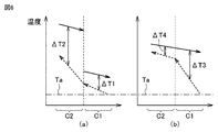
図3および図4を参照して、室外熱交換器3における冷媒および空気の温度について説明する。図4中実線矢印は冷媒の温度を示し、図4中破線矢印は空気の温度を示している。また、図4中両矢印は冷媒と空気との温度差を示している。
図4(a)は、第1熱交換部および第2熱交換部の各々の第1段S1の伝熱部P1での冷媒および空気の温度を示している。図4(b)は、第1熱交換部および第2熱交換部の各々の第4段S4の伝熱部P1での冷媒および空気の温度を示している。
図4(a)に示されるように、第1熱交換部C1の第1段S1の伝熱部P1での冷媒と空気との温度差ΔT1および第2熱交換部C2の第1段S1の伝熱部P1での冷媒と空気との温度差ΔT2が確保される。図4(b)に示されるように、第1熱交換部C1での第1段S1の伝熱部P1での冷媒と空気との温度差ΔT3および第2熱交換部C2での第4段S4の伝熱部P1での冷媒と空気との温度差ΔT4が確保される。なお、空気の吸込温度Taは一定である。
次に、実施の形態1に係る冷凍サイクル装置100の作用効果について比較例と対比して説明する。
図5および図6を参照して、実施の形態1の比較例の室外熱交換器3における第1熱交換部C1および第2熱交換部C2を流れる冷媒の流れは、実施の形態1に係る冷凍サイクル装置100の室外熱交換器3における第1熱交換部C1および第2熱交換部C2を流れる冷媒の流れと異なっている。図6(a)は、第1熱交換部C1および第2熱交換部C2の各々の第1段S1の伝熱部P1での冷媒および空気の温度を示している。図6(b)は、第1熱交換部C1および第2熱交換部C2の各々の第4段S4の伝熱部P1での冷媒および空気の温度を示している。
実施の形態1の比較例の室外熱交換器3では、第2熱交換部C2の流入路IFは第4段S4に配置された伝熱部P1である。第2熱交換部C2の流出路OFは第1段S1に配置された伝熱部P1である。第1熱交換部C1の流入路IFは第4段S4に配置された伝熱部P1である。第1熱交換部C1の流出路OFは第1段S1に配置された伝熱部P1である。
実施の形態1の比較例の室外熱交換器3では、冷媒は、第2熱交換部C2の第1段S1の伝熱部P1である流入路IFから第2熱交換部C2に流入する。冷媒は、第2熱交換部C2において第1段S1の伝熱部P1である流入路IFから第4段S4の伝熱部P1である流出路OFに流れる。その後、冷媒は、第1熱交換部C1の第4段の伝熱部P1である流入路IFから第1熱交換部C1に流入する。冷媒は、第1熱交換部C1において第4段S4の伝熱部P1である流入路IFから第1段S1の伝熱部P1である流出路OFに流れる。冷媒は、第1熱交換部C1および第2熱交換部C2をU字状に流れる。
実施の形態1の比較例の室外熱交換器3では、第2熱交換部C2の第4段S4の伝熱部P1において、冷媒と空気との温度差ΔT4が小さくなる。この要因は次のとおりである。第1熱交換部C1の第4段S4の伝熱部P1では冷媒と空気との温度差ΔT3が大きいため、熱交換量が大きくなる。したがって、第1熱交換部C1の吹出空気温度が上昇する。そして、第1熱交換部C1の吹出空気温度が第2熱交換部C2の吸込空気温度となるため、第2熱交換部C2の吸込空気温度と冷媒との温度差が小さくなる。この結果、第2熱交換部C2の第4段S4の伝熱部P1である流出路OFにおいて熱交換量が低下する。
これに対して、実施の形態1に係る冷凍サイクル装置100によれば、図2および図3を参照して、第2方向D2において、第2熱交換部C2の流出路OFは、第1熱交換部C1の流出路OFと同じ段に配置されている。このため、第2熱交換部C2の流出路OFにおいて、冷媒と空気との温度差ΔT4が小さくなる。この要因は次のとおりである。第1熱交換部C1の第4段S4の伝熱部P1では冷媒と空気との温度差ΔT3が小さいため、熱交換量が小さくなる。したがって、第1熱交換部C1の吹出空気温度の上昇が抑えられる。そして、第1熱交換部C1の吹出空気温度が第2熱交換部C2の吸込空気温度となるため、第2熱交換部C2の吸込空気温度と冷媒との温度差が大きくなる。このため、冷媒と空気との温度差ΔTが確保される。この結果、第2熱交換部C2の流出路OFにおいて熱交換量の低下が抑制される。よって、第2熱交換部C2の流出路OFにおいて熱交換器性能が向上する。
実施の形態1に係る冷凍サイクル装置100では、冷媒は非共沸混合冷媒である。したがって、実施の形態1に係る冷凍サイクル装置100によれば、地球温暖化係数が低い非共沸混合冷媒を用いつつ熱交換量の低下を抑制することができる。
実施の形態2.
実施の形態2に係る冷凍サイクル装置100は、特に説明しない限り、実施の形態1に係る冷凍サイクル装置100と同一の構成、動作および作用効果を有している。
実施の形態2に係る冷凍サイクル装置100は、特に説明しない限り、実施の形態1に係る冷凍サイクル装置100と同一の構成、動作および作用効果を有している。
図7および図8を参照して、実施の形態2に係る冷凍サイクル装置100における室外熱交換器3の構成について説明する。
実施の形態2では、室外熱交換器3は、冷媒を流すための2つのパスを有している。つまり、室外熱交換器3は、第1パスPAおよび第2パスPBを有している。なお、室外熱交換器3は、2つ以上のパスを有していてもよい。
室外熱交換器3は、第2方向D2に配置された第1熱交換領域HF1および第2熱交換領域HF2を有している。第1熱交換領域HF1および第2熱交換領域HF2は、第2方向D2に互いに隣り合うように配置されている。第1熱交換領域HF1は、第1パスPAを有している。第2熱交換領域HF2は、第2パスPBを有している。第1パスPAおよび第2パスPBは互いに並列に冷媒を流すように構成されている。第1パスPAおよび第2パスPBは第2方向D2に互いに線対称に配置されている。
第1熱交換領域HF1および第2熱交換領域HF2の各々は、第1熱交換部C1および第2熱交換部C2の各々の流入路IFおよび流出路OFを有している。第1熱交換領域HF1および第2熱交換領域HF2の各々では、第2方向D2において、第2熱交換部C2の流出路OFは、第1熱交換部C1の流出路OFと同じ段に配置されている。
第1熱交換領域HF1および第2熱交換領域HF2の各々は、第1熱交換部C1および第2熱交換部C2を有している。本実施の形態では、第1熱交換領域HF1および第2熱交換領域HF2の各々において、複数の伝熱部P1は、第1段S1~第4段S4に配置されている。
本実施の形態では、第1熱交換領域HF1において、第1熱交換部C1および第2熱交換部C2の各々の流入路IFは、第1段S1に配置された伝熱部P1である。第1熱交換部C1および第2熱交換部C2の各々の流出路OFは、第4段S4に配置された伝熱部P1である。
本実施の形態では、第2熱交換領域HF2において、第1熱交換部C1および第2熱交換部C2の各々の流入路IFは、第4段S4に配置された伝熱部P1である。第1熱交換部C1および第2熱交換部C2の各々の流出路OFは、第1段S1に配置された伝熱部P1である。
第1熱交換領域HF1では、第1熱交換部C1および第2熱交換部C2の各々において、複数の伝熱部P1は、接続部P2によって次のように接続されている。第1段S1の伝熱部P1は、第2段S2の伝熱部P1に接続部P2によって奥側で接続されている。第2段S2の伝熱部P1は、第3段S3の伝熱部P1に接続部P2によって手前側で接続されている。第3段S3の伝熱部P1は、第4段S4の伝熱部P1に接続部P2によって奥側で接続されている。第1熱交換部C1の第1段S1の伝熱部P1は、第2熱交換部C2の第4段S4の伝熱部P1に接続部P2によって手前側で接続されている。
第2熱交換領域HF2では、第1熱交換部C1および第2熱交換部C2の各々において、複数の伝熱部P1は、接続部P2によって次のように接続されている。第4段S4の伝熱部P1は、第3段S3の伝熱部P1に接続部P2によって奥側で接続されている。第3段S3の伝熱部P1は、第2段S2の伝熱部P1に接続部P2によって手前側で接続されている。第2段S2の伝熱部P1は、第1段S1の伝熱部P1に接続部P2によって奥側で接続されている。第1熱交換部C1の第4段S4の伝熱部P1は、第2熱交換部C2の第1段S1の伝熱部P1に接続部P2によって手前側で接続されている。
図8中の領域A1で示されるように、第1熱交換領域HF1および第2熱交換領域HF2の各々の第1熱交換部C1の流入路IFは、第2方向D2において互いに隣り合うように配置されている。本実施の形態では、第1熱交換領域HF1および第2熱交換領域HF2の各々の第1熱交換部C1の流入路IFは、互いに隣り合う段に配置されている。
続いて、図7および図8を参照して、室外熱交換器3における冷媒および空気の流れについて説明する。
第1熱交換領域HF1において、冷媒は、第2熱交換部C2の第1段S1の伝熱部P1である流入路IFから第2熱交換部C2に流入する。冷媒は、第2熱交換部C2において第1段S1の伝熱部P1である流入路IFから第4段S4の伝熱部P1である流出路OFに流れる。その後、冷媒は、第2熱交換部C2の流出路OFから第1熱交換部C1の流入路IFに流れる。冷媒は、第1熱交換部C1の第1段S1の伝熱部P1である流入路IFから第1熱交換部C1に流入する。冷媒は、第1熱交換部C1において第1段S1の伝熱部P1である流入路IFから第4段S4の伝熱部P1である流出路OFに流れる。その後、冷媒は、第1熱交換部C1から流出する。冷媒は、第1熱交換部C1および第2熱交換部C2を逆N字状に流れる。
第2熱交換領域HF2において、冷媒は、第2熱交換部C2の第4段S4の伝熱部P1である流入路IFから第2熱交換部C2に流入する。冷媒は、第2熱交換部C2において第4段S4の伝熱部P1である流入路IFから第1段S1の伝熱部P1である流出路OFに流れる。その後、冷媒は、第2熱交換部C2の流出路OFから第1熱交換部C1の流入路IFに流れる。冷媒は、第1熱交換部C1の第4段S4の伝熱部P1である流入路IFから第1熱交換部C1に流入する。冷媒は、第1熱交換部C1において第4段S4の伝熱部P1である流入路IFから第1段S1の伝熱部P1である流出路OFに流れる。その後、冷媒は、第1熱交換部C1から流出する。冷媒は、第1熱交換部C1および第2熱交換部C2をN字状に流れる。
第1熱交換領域HF1および第2熱交換領域HF2の各々では、冷媒は、第2熱交換部C2から第1熱交換部C1に向けて流れる。空気は、第1熱交換部C1から第2熱交換部C2に向けて流れる。そのため、第1熱交換部C1および第2熱交換部C2を流れる空気の流れに対して、第2熱交換部C2および第1熱交換部C1を流れる冷媒の流れは対向流となる。
次に、実施の形態2に係る冷凍サイクル装置100の作用効果について比較例と対比して説明する。
図9を参照して、実施の形態2の比較例の室外熱交換器3における第1熱交換部C1および第2熱交換部C2を流れる冷媒の流れは、実施の形態2に係る冷凍サイクル装置100の室外熱交換器3における第1熱交換部C1および第2熱交換部C2を流れる冷媒の流れと異なっている。
図9を参照して、実施の形態2の比較例の室外熱交換器3では、第1パスPAおよび第2パスPBは両方とも逆N字状に配置されている。つまり、第1パスPAおよび第2パスPBは第2方向D2に互いに線対称に配置されていない。図9中の領域A1で示されるように、第1熱交換領域HF1の第1熱交換部C1の流入路IFは、第2熱交換領域HF2の第1熱交換部C1の流出路OFに第2方向D2において隣り合うように配置されている。複数のフィンFによる熱伝導によって、第1熱交換領域HF1の第1熱交換部C1の流入路IFを流れる冷媒と第2熱交換領域HF2の第1熱交換部C1の流出路OFを流れる冷媒との間で熱交換が行われる。このため、第1パスPAと第2パスPBとの間で熱ロスが生じる。
これに対して、実施の形態2に係る冷凍サイクル装置によれば、図7および図8を参照して、第1熱交換領域HF1および第2熱交換領域HF2の各々の第1熱交換部C1の流入路IFは、第2方向D2において互いに隣り合うように配置されている。このため、第1熱交換領域HF1および第2熱交換領域HF2の各々の第1熱交換部C1の流入路IFを流れる冷媒の温度差を小さくすることができる。したがって、第1パスPAと第2パスPBとの間での熱ロスを小さくすることができる。
続いて、図10を参照して、実施の形態2に係る冷凍サイクル装置100の変形例について説明する。
実施の形態2に係る冷凍サイクル装置100の変形例では、第1熱交換領域HF1と第2熱交換領域HF2との段数が互いに異なっている。さらに、第1熱交換領域HF1および第2熱交換領域HF2の各々において、第1熱交換部C1と第2熱交換部C2との段数が異なっている。第1パスPAおよび第2パスPBは、第2方向D2に互いに線対称に配置されていない。
第1熱交換領域HF1および第2熱交換領域HF2の各々では、第2方向D2において、第2熱交換部C2の流入路IFは、第1熱交換部C1の流入路IFと異なる段に配置されている。第2熱交換部C2の流入路IFは、第1熱交換部C1の流入路IFと2段ずれて配置されていることが好ましい。
第1熱交換領域HF1では、複数の伝熱部P1は、第1段S1~第7段S7に配置されている。第1熱交換領域HF1では、第2熱交換部C2の流入路IFは、第1段S1に配置された伝熱部P1である。第2熱交換部C2の流出路OFは、第7段S7に配置された伝熱部P1である。第1熱交換部C1の流入路IFは、第3段S3に配置された伝熱部P1である。第1熱交換部C1の流出路OFは、第7段S7に配置された伝熱部P1である。
第2熱交換領域HF2では、複数の伝熱部P1は、第1段S1~第5段S5に配置されている。第2熱交換領域HF2では、第2熱交換部C2の流入路IFは、第3段S3に配置された伝熱部P1である。第2熱交換部C2の流出路OFは、第1段S1に配置された伝熱部P1である。第1熱交換部C1の流入路IFは、第5段S5に配置された伝熱部P1である。第1熱交換部C1の流出路OFは、第1段S1に配置された伝熱部P1である。
実施の形態2に係る冷凍サイクル装置100の変形例によれば、第1熱交換領域HF1および第2熱交換領域HF2の各々では、第2方向D2において、第2熱交換部C2の流入路IFは、第1熱交換部C1の流入路IFと異なる段に配置されている。このため、設計の自由度を向上させることができる。
実施の形態3.
実施の形態3に係る冷凍サイクル装置100は、特に説明しない限り、実施の形態1に係る冷凍サイクル装置100と同一の構成、動作および作用効果を有している。
実施の形態3に係る冷凍サイクル装置100は、特に説明しない限り、実施の形態1に係る冷凍サイクル装置100と同一の構成、動作および作用効果を有している。
図11を参照して、実施の形態3に係る冷凍サイクル装置100における室外熱交換器3の構成について説明する。
実施の形態3では、第1熱交換部C1および第2熱交換部C2の各々において、複数の伝熱部P1の内径は段毎に異なっている。第1熱交換部C1および第2熱交換部C2の各々において、伝熱部P1の内径は、第1段S1~第4段S4の順に小さくなっている。第1熱交換部C1および第2熱交換部C2の各々において、流入路IFは流出路OFよりも大きい内径を有している。
次に、実施の形態3に係る冷凍サイクル装置100の作用効果について説明する。
実施の形態3に係る冷凍サイクル装置100によれば、第1熱交換部C1および第2熱交換部C2の各々において、流入路IFは流出路OFよりも大きい内径を有している。第1熱交換部C1および第2熱交換部C2の各々では、流入路IFでの冷媒の温度は、流出路OFでの冷媒の温度よりも高い。したがって、流入路IFでは冷媒と空気との温度差が大きいため、熱交換量が大きい。他方、流出路OFでは冷媒と空気との温度差が小さいため、熱交換量が小さい。流入路IFは流出路OFよりも大きい内径を有しているため、熱交換性能を向上させることができる。
実施の形態3に係る冷凍サイクル装置100によれば、第1熱交換部C1および第2熱交換部C2の各々において、流入路IFは流出路OFよりも大きい内径を有している。第1熱交換部C1および第2熱交換部C2の各々では、流入路IFでの冷媒の温度は、流出路OFでの冷媒の温度よりも高い。したがって、流入路IFでは冷媒と空気との温度差が大きいため、熱交換量が大きい。他方、流出路OFでは冷媒と空気との温度差が小さいため、熱交換量が小さい。流入路IFは流出路OFよりも大きい内径を有しているため、熱交換性能を向上させることができる。
実施の形態4.
実施の形態4に係る冷凍サイクル装置100は、特に説明しない限り、実施の形態2に係る冷凍サイクル装置100と同一の構成、動作および作用効果を有している。
実施の形態4に係る冷凍サイクル装置100は、特に説明しない限り、実施の形態2に係る冷凍サイクル装置100と同一の構成、動作および作用効果を有している。
図12を参照して、実施の形態4に係る冷凍サイクル装置100における室外熱交換器3の構成について説明する。
実施の形態4では、送風装置6は、先端および根元を有するファン6aと、ファン6aの根元が固定されたボス6bと、ボス6bが回転可能に接続されるモータ6cとを有している。送風装置6は、たとえば、プロペラファンである。
第1熱交換領域HF1における第1熱交換部C1および第2熱交換部C2の各々の流出路OFは、第1方向D1においてファン6aの先端と重なるように配置されている。つまり、第1熱交換領域F1における第1熱交換部C1および第2熱交換部C2の各々の流出路OFは、第1方向D1から見てファン6aの先端と重なるように配置されている。第2熱交換領域HF2における第1熱交換部C1および第2熱交換部C2の各々の流出路OFは、第1方向D1においてボス6bおよびモータ6cと重なるように配置されている。
第1熱交換領域HF1および第2熱交換領域HF2の各々における第1熱交換部C1および第2熱交換部C2の各々の流入路IFは、第1方向D1においてファン6aの先端と根元との中央と重なるように配置されている。たとえば、ファン6aの中央は、ファン6aの先端と根元との中間を挟み、かつ第1方向D1においてファン6aの先端と根元との距離の40%以上60%以下の部分である。
続いて、送風装置6によって生じる風の風速分布について説明する。この風速分布は、フィンの積幅方向(積層方向)に平均した風速である。ファン6aおよびボス6bは略円形であるため、フィンの積幅方向に積算した場合、ファン6aの先端(外縁部)L1ではファン6aの中央(中心部分)L2に比べて、風速は小さい。ボス6bおよびモータ6cが配置された送風装置6の中央部L3ではファン6aの中央(中心部分)L2に比べて風速は小さい。つまり、ファン6aの中央(中心部分)L2ではファン6aの先端(外縁部)L1および送風装置6の中央部L3に比べて風速は大きい。
次に、実施の形態3に係る冷凍サイクル装置100の作用効果について説明する。
実施の形態4に係る冷凍サイクル装置100によれば、第1熱交換領域HF1および第2熱交換領域HF2の各々における第1熱交換部C1および第2熱交換部C2の各々の流入路IFは、第1方向D1においてファン6aの先端と根元との中央と重なるように配置されている。このため、第1熱交換部C1および第2熱交換部C2の各々の流入路IFを風速(風量)が大きいファン6aの中央と重なるように配置することができる。したがって、吹出温度を低くすることができる。
実施の形態4に係る冷凍サイクル装置100によれば、第1熱交換領域HF1および第2熱交換領域HF2の各々における第1熱交換部C1および第2熱交換部C2の各々の流入路IFは、第1方向D1においてファン6aの先端と根元との中央と重なるように配置されている。このため、第1熱交換部C1および第2熱交換部C2の各々の流入路IFを風速(風量)が大きいファン6aの中央と重なるように配置することができる。したがって、吹出温度を低くすることができる。
実施の形態5.
実施の形態5に係る冷凍サイクル装置100は、特に説明しない限り、実施の形態2に係る冷凍サイクル装置100と同一の構成、動作および作用効果を有している。
実施の形態5に係る冷凍サイクル装置100は、特に説明しない限り、実施の形態2に係る冷凍サイクル装置100と同一の構成、動作および作用効果を有している。
図13を参照して、実施の形態5に係る冷凍サイクル装置100における室外熱交換器3の構成について説明する。
実施の形態5では、室外熱交換器3は、第1熱交換領域HF1および第2熱交換領域HF2の各々における第1熱交換部C1の流出路OFに接続されたサブクールラインSCLをさらに有している。サブクールラインSCLは、冷媒を過冷却状態に冷却するように構成されている。サブクールラインSCLは、第2方向D2において第1熱交換領域HF1における第1熱交換部C1の流出路OFに隣り合うように配置されている。
実施の形態5では、室外熱交換器3は、第1熱交換領域HF1および第2熱交換領域HF2の組を2つ有している。第1熱交換領域HF1および第2熱交換領域HF2の第1組ST1および第2組ST2は、第2方向D2に配置されている。第1熱交換領域HF1および第2熱交換領域HF2の第1組ST1および第2組のST2各々において、サブクールラインSCLは、第2方向D2において第1熱交換領域HF1に対して第2熱交換領域HF2と反対側に配置されている。
第1熱交換領域HF1および第2熱交換領域HF2の第1組ST1および第2組ST2の各々は、冷媒の温度が高い箇所R1および冷媒の温度が低い箇所R1を有している。第1熱交換領域HF1および第2熱交換領域HF2の第2組ST2のサブクールラインSCLは、冷媒の温度が低い箇所R2の間に挟まれるように配置されている。
次に、実施の形態5に係る冷凍サイクル装置100の作用効果について比較例と対比して説明する。
図14を参照して、実施の形態5の比較例では、第1熱交換領域HF1の第1パスPAおよび第2熱交換領域HF2の第2パスPBはそれぞれU字状に構成されている。サブクールラインSCLは、第2方向D2において第1熱交換領域HF1の第1熱交換部C1の流入路IFに隣り合うように配置されている。このため、第1パスPAとサブクールラインSCLとの間で冷媒の温度差が大きくなる。このため、第1パスPAとサブクールラインSCLとの間の熱ロスが大きくなる。
これに対して、実施の形態5に係る冷凍サイクル装置100では、サブクールラインSCLは、第2方向D2において第1熱交換領域HF1における第1熱交換部C1の流出路OFに隣り合うように配置されている。このため、第1熱交換領域HF1における第1熱交換部C1の流出路OFとサブクールラインSCLとの間で冷媒の温度差が小さくなる。したがって、第1パスPAとサブクールラインSCLとの間での熱ロスを小さくすることができる。よって、サブクールラインSCLでの熱交換量の低下を抑制することができる。
上記の各実施の形態は適宜組み合わされてもよい。
今回開示された実施の形態はすべての点で例示であって制限的なものではないと考えられるべきである。本開示の範囲は上記した説明ではなくて請求の範囲によって示され、請求の範囲と均等の意味および範囲内でのすべての変更が含まれることが意図される。
今回開示された実施の形態はすべての点で例示であって制限的なものではないと考えられるべきである。本開示の範囲は上記した説明ではなくて請求の範囲によって示され、請求の範囲と均等の意味および範囲内でのすべての変更が含まれることが意図される。
1 圧縮機、2 四方弁、3 室外熱交換器、4 減圧弁、5 室内熱交換器、6,7 送風装置、6a ファン、6b ボス、6c モータ、100 冷凍サイクル装置、101 室外機、102 室内機、C1 第1熱交換部、C2 第2熱交換部、CD 制御装置、D1 第1方向、D2 第2方向、D3 第3方向、F フィン、HF1 第1熱交換領域、HF2 第2熱交換領域、IF 流入路、OF 流出路、P 伝熱管、P1 伝熱部、P2 接続部、PA 第1パス、PB 第2パス、RC 冷媒回路、SCL サブクールライン。
Claims (6)
- 圧縮機と、凝縮器と、減圧弁と、蒸発器とを有する冷媒回路と、
前記冷媒回路を、前記圧縮機、前記凝縮器、前記減圧弁、前記蒸発器の順に流れる冷媒とを備え、
前記冷媒は非共沸混合冷媒であり、
前記凝縮器および前記蒸発器の少なくともいずれかは、空気が流れる第1方向において、風上側に配置された第1熱交換部および風下側に配置された第2熱交換部を有し、
前記第1熱交換部および前記第2熱交換部の各々は、前記第1方向に交差する第2方向において、複数段に配置された前記冷媒の流入路および流出路を有し、
前記冷媒は前記第2熱交換部の前記流出路から前記第1熱交換部の前記流入路に流れ、
前記第2方向において、前記第2熱交換部の前記流出路は、前記第1熱交換部の前記流出路と同じ段に配置されている、冷凍サイクル装置。 - 前記第1熱交換部および前記第2熱交換部の各々において、前記流入路は前記流出路よりも大きい内径を有している、請求項1に記載の冷凍サイクル装置。
- 前記凝縮器および前記蒸発器の少なくともいずれかは、前記第2方向に配置された第1熱交換領域および第2熱交換領域を有し、
前記第1熱交換領域および前記第2熱交換領域の各々は、前記第1熱交換部および前記第2熱交換部の各々の前記流入路および前記流出路を有し、
前記第1熱交換領域および前記第2熱交換領域の各々において、前記冷媒は前記第2熱交換部の前記流出路から前記第1熱交換部の前記流入路に流れ、
前記第1熱交換領域および前記第2熱交換領域の各々では、前記第2方向において、前記第2熱交換部の前記流出路は、前記第1熱交換部の前記流出路と同じ段に配置されており、
前記第1熱交換領域および前記第2熱交換領域の各々の前記第1熱交換部の前記流入路は、前記第2方向において互いに隣り合うように配置されている、請求項1に記載の冷凍サイクル装置。 - 前記第1熱交換領域および前記第2熱交換領域の各々では、前記第2方向において、前記第2熱交換部の前記流入路は、前記第1熱交換部の前記流入路と異なる段に配置されている、請求項3に記載の冷凍サイクル装置。
- 送風装置をさらに備え、
前記送風装置は、先端および根元を有するファンと、前記ファンの前記根元が固定されたボスと、前記ボスが回転可能に接続されるモータとを有し、
前記第1熱交換領域における前記第1熱交換部および前記第2熱交換部の各々の前記流出路は、前記第1方向において前記ファンの前記先端と重なるように配置されており、
前記第2熱交換領域における前記第1熱交換部および前記第2熱交換部の各々の前記流出路は、前記第1方向において前記ボスおよび前記モータと重なるように配置されており、
前記第1熱交換領域および前記第2熱交換領域の各々における前記第1熱交換部および前記第2熱交換部の各々の前記流入路は、前記第1方向において前記ファンの前記先端と前記根元との中央と重なるように配置されている、請求項3に記載の冷凍サイクル装置。 - 前記凝縮器および前記蒸発器の少なくともいずれかは、前記第1熱交換領域および前記第2熱交換領域の各々における前記第1熱交換部の前記流出路に接続されたサブクールラインをさらに有し、
前記サブクールラインは、前記第2方向において前記第1熱交換領域における前記第1熱交換部の前記流出路に隣り合うように配置されている、請求項3に記載の冷凍サイクル装置。
Priority Applications (4)
| Application Number | Priority Date | Filing Date | Title |
|---|---|---|---|
| PCT/JP2020/017058 WO2021214832A1 (ja) | 2020-04-20 | 2020-04-20 | 冷凍サイクル装置 |
| US17/918,189 US20230126980A1 (en) | 2020-04-20 | 2020-04-20 | Refrigeration Cycle Apparatus |
| JP2022516487A JPWO2021214832A1 (ja) | 2020-04-20 | 2020-04-20 | |
| EP20932319.5A EP4141348A4 (en) | 2020-04-20 | 2020-04-20 | REFRIGERATION CIRCUIT DEVICE |
Applications Claiming Priority (1)
| Application Number | Priority Date | Filing Date | Title |
|---|---|---|---|
| PCT/JP2020/017058 WO2021214832A1 (ja) | 2020-04-20 | 2020-04-20 | 冷凍サイクル装置 |
Publications (1)
| Publication Number | Publication Date |
|---|---|
| WO2021214832A1 true WO2021214832A1 (ja) | 2021-10-28 |
Family
ID=78270390
Family Applications (1)
| Application Number | Title | Priority Date | Filing Date |
|---|---|---|---|
| PCT/JP2020/017058 WO2021214832A1 (ja) | 2020-04-20 | 2020-04-20 | 冷凍サイクル装置 |
Country Status (4)
| Country | Link |
|---|---|
| US (1) | US20230126980A1 (ja) |
| EP (1) | EP4141348A4 (ja) |
| JP (1) | JPWO2021214832A1 (ja) |
| WO (1) | WO2021214832A1 (ja) |
Citations (12)
| Publication number | Priority date | Publication date | Assignee | Title |
|---|---|---|---|---|
| JPS432682Y1 (ja) * | 1964-12-28 | 1968-02-03 | ||
| JPS54157308A (en) * | 1978-06-02 | 1979-12-12 | Hitachi Ltd | Outdoor unit of separate type air conditioner |
| JPS6380465U (ja) * | 1986-11-14 | 1988-05-27 | ||
| JPH06272998A (ja) * | 1993-03-18 | 1994-09-27 | Toshiba Corp | 冷凍装置 |
| JPH06307738A (ja) * | 1993-04-21 | 1994-11-01 | Hitachi Ltd | 非共沸混合冷媒用凝縮器 |
| JPH07269985A (ja) | 1994-03-31 | 1995-10-20 | Toshiba Corp | 熱交換器 |
| JPH07280375A (ja) * | 1994-04-06 | 1995-10-27 | Hitachi Ltd | 空気調和装置 |
| JPH10281574A (ja) * | 1997-04-07 | 1998-10-23 | Hitachi Ltd | 空気調和機 |
| JP2001066017A (ja) * | 1999-08-27 | 2001-03-16 | Hitachi Ltd | 空気調和機 |
| JP2013113493A (ja) * | 2011-11-29 | 2013-06-10 | Panasonic Corp | 熱交換素子とそれを用いた熱交換換気機器 |
| JP2014206054A (ja) * | 2013-04-10 | 2014-10-30 | 日立アプライアンス株式会社 | 空気調和装置 |
| JP2016114263A (ja) * | 2014-12-12 | 2016-06-23 | ジョンソンコントロールズ ヒタチ エア コンディショニング テクノロジー(ホンコン)リミテッド | 空気調和機 |
Family Cites Families (5)
| Publication number | Priority date | Publication date | Assignee | Title |
|---|---|---|---|---|
| JP2008111622A (ja) * | 2006-10-31 | 2008-05-15 | Toshiba Kyaria Kk | 熱交換器、これを用いた空気調和機の室外機 |
| JP5956743B2 (ja) * | 2011-11-29 | 2016-07-27 | 日立アプライアンス株式会社 | 空気調和機 |
| WO2013084432A1 (ja) * | 2011-12-06 | 2013-06-13 | パナソニック株式会社 | 空気調和機及び冷凍サイクル装置 |
| JP5644889B2 (ja) * | 2013-04-30 | 2014-12-24 | ダイキン工業株式会社 | 空気調和機の室内ユニット |
| CN109477669B (zh) * | 2016-08-09 | 2020-09-22 | 三菱电机株式会社 | 热交换器以及具备该热交换器的制冷循环装置 |
-
2020
- 2020-04-20 US US17/918,189 patent/US20230126980A1/en active Pending
- 2020-04-20 WO PCT/JP2020/017058 patent/WO2021214832A1/ja unknown
- 2020-04-20 EP EP20932319.5A patent/EP4141348A4/en active Pending
- 2020-04-20 JP JP2022516487A patent/JPWO2021214832A1/ja active Pending
Patent Citations (12)
| Publication number | Priority date | Publication date | Assignee | Title |
|---|---|---|---|---|
| JPS432682Y1 (ja) * | 1964-12-28 | 1968-02-03 | ||
| JPS54157308A (en) * | 1978-06-02 | 1979-12-12 | Hitachi Ltd | Outdoor unit of separate type air conditioner |
| JPS6380465U (ja) * | 1986-11-14 | 1988-05-27 | ||
| JPH06272998A (ja) * | 1993-03-18 | 1994-09-27 | Toshiba Corp | 冷凍装置 |
| JPH06307738A (ja) * | 1993-04-21 | 1994-11-01 | Hitachi Ltd | 非共沸混合冷媒用凝縮器 |
| JPH07269985A (ja) | 1994-03-31 | 1995-10-20 | Toshiba Corp | 熱交換器 |
| JPH07280375A (ja) * | 1994-04-06 | 1995-10-27 | Hitachi Ltd | 空気調和装置 |
| JPH10281574A (ja) * | 1997-04-07 | 1998-10-23 | Hitachi Ltd | 空気調和機 |
| JP2001066017A (ja) * | 1999-08-27 | 2001-03-16 | Hitachi Ltd | 空気調和機 |
| JP2013113493A (ja) * | 2011-11-29 | 2013-06-10 | Panasonic Corp | 熱交換素子とそれを用いた熱交換換気機器 |
| JP2014206054A (ja) * | 2013-04-10 | 2014-10-30 | 日立アプライアンス株式会社 | 空気調和装置 |
| JP2016114263A (ja) * | 2014-12-12 | 2016-06-23 | ジョンソンコントロールズ ヒタチ エア コンディショニング テクノロジー(ホンコン)リミテッド | 空気調和機 |
Non-Patent Citations (1)
| Title |
|---|
| See also references of EP4141348A4 |
Also Published As
| Publication number | Publication date |
|---|---|
| JPWO2021214832A1 (ja) | 2021-10-28 |
| EP4141348A1 (en) | 2023-03-01 |
| US20230126980A1 (en) | 2023-04-27 |
| EP4141348A4 (en) | 2023-08-09 |
Similar Documents
| Publication | Publication Date | Title |
|---|---|---|
| US10386081B2 (en) | Air-conditioning device | |
| WO2019239446A1 (ja) | 空気調和装置の室外機及び空気調和装置 | |
| WO2013160957A1 (ja) | 熱交換器、室内機及び冷凍サイクル装置 | |
| JP5195733B2 (ja) | 熱交換器及びこれを備えた冷凍サイクル装置 | |
| TW201825838A (zh) | 除濕裝置 | |
| WO2021065913A1 (ja) | 蒸発器、およびそれを備えた冷凍サイクル装置 | |
| WO2021214832A1 (ja) | 冷凍サイクル装置 | |
| JP2019215161A (ja) | 空気調和装置の室外機及び空気調和装置 | |
| JP7414845B2 (ja) | 冷凍サイクル装置 | |
| JP7123238B2 (ja) | 冷凍サイクル装置 | |
| WO2019155571A1 (ja) | 熱交換器および冷凍サイクル装置 | |
| JP4983878B2 (ja) | 熱交換器及びこの熱交換器を備えた冷蔵庫、空気調和機 | |
| WO2023188421A1 (ja) | 室外機およびそれを備えた空気調和装置 | |
| JP2008121995A (ja) | 空気調和機 | |
| TWI810896B (zh) | 除濕裝置 | |
| JP7229255B2 (ja) | 室外機、及び、冷凍サイクル装置 | |
| WO2023281655A1 (ja) | 熱交換器および冷凍サイクル装置 | |
| WO2024203167A1 (ja) | 熱交換器及び熱交換器を備えた冷凍サイクル装置 | |
| JP7050538B2 (ja) | 熱交換器および空気調和機 | |
| WO2023281656A1 (ja) | 熱交換器および冷凍サイクル装置 | |
| WO2022157979A1 (ja) | 室外機、空気調和機および室外機の設計方法 | |
| WO2023175926A1 (ja) | 空気調和装置の室外機および空気調和装置 | |
| CN118946764A (en) | Outdoor unit and air conditioner provided with same | |
| JP3749193B2 (ja) | 空気調和装置 | |
| WO2021245877A1 (ja) | 熱交換器および冷凍サイクル装置 |
Legal Events
| Date | Code | Title | Description |
|---|---|---|---|
| 121 | Ep: the epo has been informed by wipo that ep was designated in this application |
Ref document number: 20932319 Country of ref document: EP Kind code of ref document: A1 |
|
| ENP | Entry into the national phase |
Ref document number: 2022516487 Country of ref document: JP Kind code of ref document: A |
|
| NENP | Non-entry into the national phase |
Ref country code: DE |
|
| ENP | Entry into the national phase |
Ref document number: 2020932319 Country of ref document: EP Effective date: 20221121 |