WO2021210484A1 - 針組立体 - Google Patents
針組立体 Download PDFInfo
- Publication number
- WO2021210484A1 WO2021210484A1 PCT/JP2021/014875 JP2021014875W WO2021210484A1 WO 2021210484 A1 WO2021210484 A1 WO 2021210484A1 JP 2021014875 W JP2021014875 W JP 2021014875W WO 2021210484 A1 WO2021210484 A1 WO 2021210484A1
- Authority
- WO
- WIPO (PCT)
- Prior art keywords
- valve housing
- air bleeding
- valve body
- component
- needle
- Prior art date
- Legal status (The legal status is an assumption and is not a legal conclusion. Google has not performed a legal analysis and makes no representation as to the accuracy of the status listed.)
- Ceased
Links
Images




Classifications
-
- A—HUMAN NECESSITIES
- A61—MEDICAL OR VETERINARY SCIENCE; HYGIENE
- A61M—DEVICES FOR INTRODUCING MEDIA INTO, OR ONTO, THE BODY; DEVICES FOR TRANSDUCING BODY MEDIA OR FOR TAKING MEDIA FROM THE BODY; DEVICES FOR PRODUCING OR ENDING SLEEP OR STUPOR
- A61M25/00—Catheters; Hollow probes
- A61M25/01—Introducing, guiding, advancing, emplacing or holding catheters
- A61M25/06—Body-piercing guide needles or the like
-
- A—HUMAN NECESSITIES
- A61—MEDICAL OR VETERINARY SCIENCE; HYGIENE
- A61M—DEVICES FOR INTRODUCING MEDIA INTO, OR ONTO, THE BODY; DEVICES FOR TRANSDUCING BODY MEDIA OR FOR TAKING MEDIA FROM THE BODY; DEVICES FOR PRODUCING OR ENDING SLEEP OR STUPOR
- A61M39/00—Tubes, tube connectors, tube couplings, valves, access sites or the like, specially adapted for medical use
- A61M39/02—Access sites
- A61M39/06—Haemostasis valves, i.e. gaskets sealing around a needle, catheter or the like, closing on removal thereof
Definitions
- the present invention relates to a needle assembly such as an indwelling needle with a valve body.
- some needle assemblies such as indwelling needles for veins are provided with a valve body to prevent backflow of blood.
- the needle assembly has, for example, a structure in which the valve body is housed in the lumen of the valve housing connected to the proximal end side of the needle body. This prevents blood that has entered the lumen of the valve housing from flowing out to the outside, for example, in a needle assembly that has been punctured into a vein.
- Examples of the needle assembly provided with such a valve body include Japanese Patent Application Laid-Open No. 2002-263197 (Patent Document 1).
- valve body is an elastic body that can switch between communication and blocking of the inner cavity of the valve housing by deformation, the outer surface of the valve body is particularly distorted after assembly to the valve housing, and the cross section of the air bleeding passage. The shape and cross-sectional area can change. Therefore, there was a possibility that the air could not be released stably.
- An object of the present invention is to provide a needle assembly having a novel structure capable of preventing blood leakage while discharging air on the needle tip side of the valve body.
- the first aspect is a hollow needle body, a tubular valve housing provided on the base end side of the needle body, and communication and blocking of the cavity of the valve housing by being housed in the cavity of the valve housing.
- a needle assembly including a valve body for switching between the above, and an air bleeding passage penetrating the valve housing is provided, and the air bleeding passage is located on the needle tip side of the needle body with respect to the valve body.
- a liquid reservoir portion that is communicated with the lumen and has a partially enlarged cross-sectional area is provided in the middle of the air bleeding passage.
- the cross-sectional shape and cross-sectional area of the air bleeding passage are stabilized by providing the air bleeding passage through the valve housing which is harder than the valve body.
- the second aspect is that in the needle assembly described in the first aspect, the air bleeding passages are provided at a plurality of locations in the circumferential direction in the valve housing.
- air can be efficiently discharged through a plurality of air bleeding passages. Further, it is possible to reduce the passage cross-sectional area of each air bleeding passage while ensuring the total cross-sectional area of the air bleeding passage required for air discharge, and it is possible to suppress the infiltration of blood into the air bleeding passage.
- the third aspect is that in the needle assembly described in the first or second aspect, the liquid reservoir portion is an annular shape continuous in the circumferential direction of the valve housing.
- the volume of the liquid reservoir can be increased, and the leakage of blood through the air bleeding passage can be prevented more effectively.
- a fourth aspect is the second aspect in which the valve housing is connected to the first component and the proximal end side of the first component in the needle assembly described in any one of the first to third aspects. It is provided with constituent members, and the air bleeding passage is formed between the first constituent members and the second constituent members.
- the air bleeding passage that penetrates one member is formed by forming the air bleeding passage between the first component and the second component, as compared with the case where the air bleeding passage is formed.
- the cross-sectional shape and cross-sectional area of the air bleeding passage can be designed with a greater degree of freedom. In particular, by reducing the cross-sectional area of the air bleeding passage, the amount of blood entering the air bleeding passage can be suppressed.
- a fifth aspect is that in the needle assembly described in the fourth aspect, the second component is fitted and connected to the inner circumference of the first component, and the second component is connected.
- the liquid reservoir is formed by a recess that opens on the outer peripheral surface of the fitting portion to the first constituent member.
- the opening of the recess provided in the second constituent member is opened by fitting the second constituent member into the inner circumference of the first constituent member. Since the liquid reservoir portion is formed by being covered with the liquid reservoir portion, the liquid reservoir portion can be easily formed between the second constituent member and the first constituent member.
- the recess for forming the liquid reservoir By forming the recess for forming the liquid reservoir so as to open on the outer peripheral surface of the second component member, the recess can be formed accurately, and the leakage of blood through the air bleeding passage is more effective. Can be prevented.
- a sixth aspect is the needle assembly according to the fourth or fifth aspect, wherein the valve body and the second configuration extend inward in the radial direction to the base end portion of the first component member.
- a support surface is provided on at least one of the members, and a recessed groove forming the air bleeding passage is opened in the support surface, and the operation member is inserted from the base end side with respect to the valve housing.
- the valve body is deformed to the tip end side so that the valve body blocks the air bleeding passage.
- the air bleeding passage can be stably realized as compared with the case where the valve body is provided with the concave groove to form the air bleeding passage. Further, since the end of the air bleeding passage is formed in the vicinity of the valve, when the operating member is inserted from the base end of the valve housing, the air bleeding passage and the inner cavity of the valve housing are surely in a non-communication state. Therefore, even if the pressure in the valve housing becomes large, the pressure does not easily act in the air bleeding passage, and it is possible to prevent the liquid in the air bleeding passage from leaking to the outside.
- a seventh aspect is the needle assembly according to any one of the first to sixth aspects, which is inserted from the proximal end side with respect to the valve housing to close the lumen of the valve housing.
- a cap member that deforms the valve body to the tip side and closes the air bleeding passage with the valve body is provided, and the cap member is removable from the valve housing.
- the cap member when the needle body is placed in a state of being punctured into a blood vessel of a patient, the cap member is inserted into the lumen of the valve housing and attached.
- the lumen of the valve housing and the air bleeding passage can be closed respectively. This makes it possible to prevent blood from leaking through the lumen of the valve housing and the air bleeding passage, and for example, it is possible to hold the needle assembly in an indwelling state for a relatively long time.
- the eighth aspect is a hollow needle body, a tubular valve housing provided on the base end side of the needle body, and communication and blocking of the cavity of the valve housing by being housed in the cavity of the valve housing.
- a needle assembly including a valve body for switching between the above and a holding portion protruding from the inner peripheral surface of the valve housing, and the holding portion is partially provided in the circumferential direction of the valve housing. At the same time, it has an inclined surface that inclines so that the protruding height increases toward the valve body side.
- the holding portion is an inclined surface
- the valve body is moved from the proximal end side to the needle tip side in the lumen of the valve housing.
- the valve body is guided by the inclined surface of the holding portion to easily get over the holding portion, and the valve body can be easily inserted axially into the lumen of the valve housing.
- the holding portion is partially provided in the circumferential direction of the valve housing, the contact area between the valve body and the holding portion is small when the valve body is guided by sliding contact with the inclined surface of the holding portion. Therefore, the force required to insert the valve body into the lumen of the valve housing in the axial direction is reduced, and the work of attaching the valve body to the valve housing becomes easy.
- the needle assembly in the needle assembly, it is possible to prevent blood leakage while discharging air on the needle tip side of the valve body.
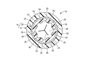
- FIG. 1 is an enlarged view showing a cross section of III-III in FIG.
- FIG. 1 is an enlarged view showing an IV-IV cross section of FIG.
- FIG. 3 is a vertical cross-sectional view of the needle assembly shown in FIG. 1, showing a state in which the valve body is opened by a pusher.
- FIGS. 1 to 4 show an indwelling needle 10 as a first embodiment of a needle assembly having a structure according to the present invention.
- the indwelling needle 10 has a structure in which the valve housing 14 is connected to the base end side of the cannula 12 as a needle body.
- the tip end side refers to the left side in FIG. 2 which is the needle tip side of the cannula 12
- the proximal end side refers to the right side in FIG. 2 which is the side opposite to the needle tip of the cannula 12.
- the axial direction means, in principle, the left-right direction in FIG. 2, which is the needle axis direction of the cannula 12.
- the cannula 12 has a hollow cylindrical shape and is formed of, for example, a soft synthetic resin.
- the cannula 12 may have a tapered shape in which the outer peripheral surface of the tip portion (not shown) gradually decreases in diameter toward the tip side. Further, a plurality of through holes may be formed in the peripheral wall of the tip portion of the cannula 12 to facilitate the inflow of a liquid such as blood into the cannula 12.
- the cannula 12 may be rigid and may be formed of, for example, metal.
- the valve housing 14 has a cylindrical shape as a whole and has a lumen 16 penetrating in the axial direction.
- the valve housing 14 is harder than the valve body 44 described later, and is formed of, for example, a hard synthetic resin.
- the valve housing 14 includes a first component 18 connected to the cannula 12 and a second component 20 connected to the first component 18.
- the first constituent member 18 has a tip portion 22 having a tapered cylindrical shape having a small diameter toward the tip as a whole.
- a cannula 12 is inserted into the tip portion 22 of the first component 18 from the tip end side, and the cannula 12 is fixed to the inner peripheral surface of the tip portion 22.
- the valve housing 14 of the present embodiment is a needle fixing portion, and the cannula 12 is directly connected to the first component 18 constituting the tip portion.
- the first constituent member 18 has a substantially cylindrical connecting cylinder portion 24 protruding from the tip portion 22 toward the base end side.
- the connecting cylinder portion 24 is thinner and has a larger inner diameter than the base end of the tip portion 22, and the inner peripheral portion of the base end surface of the tip portion 22 is an annular portion located on the inner circumference of the tip end of the connecting cylinder portion 24. It is said to be a support surface 25.
- the support surface 25 is provided at the base end portion of the tip portion 22 of the first constituent member 18, and extends inward in the radial direction.
- a concave groove 26 is formed on the inner peripheral surface and the support surface 25 of the connecting cylinder portion 24 of the first component member 18.
- the concave groove 26 is partially provided in the circumferential direction of the first constituent member 18.
- the concave groove 26 extends linearly in the radial direction on the support surface 25, and also extends linearly in the axial direction on the inner peripheral surface of the connecting cylinder portion 24.
- One end of the groove 26 reaches the inner peripheral end of the support surface 25, and the other end reaches the base end of the connecting cylinder 24.
- the number of the concave grooves 26 is not particularly limited, but is preferably a plurality, and in the present embodiment, the eight concave grooves 26 are arranged at substantially equal intervals in the circumferential direction.
- the second component 20 has a substantially cylindrical shape as a whole, and a male screw portion 28 protruding to the outer circumference is provided at the base end portion.
- the base end portion of the inner peripheral surface of the second component 20 is set with a female luer taper having a smaller diameter toward the tip end side, and is in close contact with the outer peripheral surface of the male connector 52, which will be described later.
- the second component 20 is provided with a positioning portion 30 projecting to the outer periphery at an intermediate portion in the axial direction.
- the protruding height of the positioning portion 30 gradually increases toward the tip end.
- the positioning portion 30 is provided over the entire circumference, and as shown in FIG. 3, communication grooves 32 are provided at a plurality of locations in the circumferential direction.
- the first holding portion 34 and the second holding portion 36 as holding portions project from the inner peripheral surface of the second constituent member 20.
- the first holding portion 34 is partially provided in the circumferential direction of the second component member 20 and extends linearly in the axial direction.
- a plurality of the first holding portions 34 are provided so as to be separated from each other in the circumferential direction of the second constituent member 20, and in the present embodiment, eight first holding portions 34 are provided in the circumferential direction of the second constituent member 20 and the like. Arranged at intervals.
- the first holding portion 34 is an inclined surface 38 whose protruding end surface is inclined inward toward the tip side in the axial direction, and is directed toward the tip side in the axial direction, which is the arrangement side of the valve body 44, which will be described later.
- the protruding height is large.
- the inclined surface 38 is inclined at a substantially constant inclination angle, but the inclination angle may be changed gradually or stepwise.
- the axial length of the first holding portion 34 is longer than the axial length of the valve body 44, which will be described later.
- the second holding portion 36 is partially provided in the circumferential direction of the second component member 20 and extends linearly in the axial direction.
- a plurality of the second holding portions 36 are provided so as to be separated from each other in the circumferential direction of the second constituent member 20, and in the present embodiment, eight second holding portions 36 are provided in the circumferential direction of the second constituent member 20 and the like. Arranged at intervals.
- the second holding portion 36 is arranged apart from the first holding portion 34 toward the tip end side, and a valve body accommodating portion 40 is provided between the first holding portion 34 and the second holding portion 36 in the axial direction. Has been done.
- Both the protruding end face of the first holding portion 34 and the protruding end face of the second holding portion 36 are located so as to protrude inward from the inner surface of the peripheral wall of the valve body accommodating portion 40.
- the protrusion height of the second holding portion 36 is substantially constant in the axial direction.
- the axial length of the first holding portion 34 is longer than the axial length of the second holding portion 36.
- the protruding height of the first holding portion 34 and the protruding height of the second holding portion 36 may be different from each other, but are substantially the same in the present embodiment.
- the second holding portion 36 is arranged at a position separated from the first holding portion 34 in the circumferential direction of the second constituent member 20, and in the present embodiment, the first holding portion 34 and the second holding portion 36 are arranged in the circumferential direction. Are arranged alternately.
- the inner peripheral surface of the second component 20 including the first holding portion 34 and the second holding portion 36 is divided in the axial direction. It can be molded by a simple mold structure. That is, the end face of the first holding portion 34 on the valve body accommodating portion 40 side, the both end faces and the protruding end faces of the second holding portion 36 are molded by the mold on the tip side, and the first holding is performed by the mold on the base end side. Both side end faces and protruding end faces of the portion 34 and the end faces of the second holding portion 36 on the valve body accommodating portion 40 side can be formed.
- a recess 42 is open on the outer peripheral surface of the second component 20.
- the recess 42 is provided at the tip of the second constituent member 20 that is fitted into the connecting cylinder portion 24 of the first constituent member 18.
- the recess 42 is arranged in the middle of the tip portion of the second constituent member 20 off the tip in the axial direction, and is preferably located in the center of the tip portion of the second component 20 in the axial direction.
- the recess 42 of the present embodiment is an annular shape that extends continuously in the circumferential direction.
- the cross-sectional shape of the recess 42 is not particularly limited, but in the present embodiment, it is substantially semicircular.
- the recess 42 is arranged on the base end side in the axial direction with respect to the valve body accommodating portion 40. It is desirable that the radial depth dimension of the recess 42 is larger than the depth dimension of the recess 26 of the first component member 18.
- a valve body 44 is housed in the inner circumference of the second component 20.
- the valve body 44 is an elastic body formed of rubber or the like, has a substantially disk shape, and has a notch 46 penetrating in the axial direction.
- the shape of the notch 46 is not limited, but is, for example, radial, and in the present embodiment, it is radial extending from the center to the outer circumference in three directions. It is desirable that the outer diameter dimension of the valve body 44 is larger than the inner diameter dimension of the second component 20 in the valve body accommodating portion 40.
- the valve body 44 is inserted into the second component 20 from the base end.
- the base end opening of the second component 20 has a larger diameter than the valve body 44, and the valve body 44 can be easily inserted into the base end opening of the second component 20.
- the valve body 44 moves on the inner circumference of the second component 20 toward the tip end side, gets over the first holding portion 34 toward the tip end side, and is inserted into the valve body accommodating portion 40.
- the valve body 44 gets over the first holding portion 34, it comes into contact with the inclined surface 38 which is the protruding end surface of the first holding portion 34, and gets over the first holding portion 34 while being gradually compressed by the inclined surface 38.
- the valve body 44 smoothly gets over the first holding portion 34 without being caught by the first holding portion 34, and is guided to the valve body accommodating portion 40.
- the first holding portion 34 is longer than the valve body 44 in the axial direction, the first holding portion 34 is not locally pressed against the outer peripheral surface of the valve body 44 and bites into the outer peripheral surface of the valve body 44. The surface is pressed against the inclined surface 38 of the first holding portion 34 in a wide range. Further, since the first holding portion 34 is made longer than the second holding portion 36, the inclination angle of the inclined surface 38 of the first holding portion 34 is reduced, and the valve body accommodating portion 40 of the valve body 44 is accommodated. The insertion work of is facilitated. Further, since the second holding portion 36 is shortened, the length of the second constituent member 20 can be shortened, and the valve housing 14 can be made compact in the axial direction.
- the first holding portion 34 and the second holding portion 36 are located on both sides in the axial direction with respect to the valve body 44 inserted into the valve body accommodating portion 40. Then, the movement of the valve body 44 toward the proximal end side is restricted by locking with the first holding portion 34, and the movement toward the distal end side is restricted by locking with the second holding portion 36. 2 Positioned with respect to the component 20.
- the first holding portion 34 and the second holding portion 36 for positioning the valve body 44 are both provided on the second constituent member 20, and the valve body 44 is the first holding portion 34.
- the valve body 44 is held in the positioned state by the second component 20 by overcoming the above. According to the structure of the first holding portion 34 and the second holding portion 36, the valve body 44 can be easily positioned and held by one member without sandwiching the valve body 44 between the two members. ..
- valve body 44 Since the valve body 44 that has reached the valve body accommodating portion 40 is released from contact with the first holding portion 34, the compression deformation due to the contact with the first holding portion 34 is released. Since the inner diameter of the valve body accommodating portion 40 is smaller than the outer diameter dimension of the valve body 44, the valve body 44 is arranged in the valve body accommodating portion 40 in a state of being compressed in the radial direction. As a result, the inner surfaces of the notches 46 are in close contact with each other, the notches 46 are liquid-tightly sealed, and the lumen of the second component 20 is blocked by the valve body 44.
- the second component 20 to which the valve body 44 is attached is connected to the first component 18 by fitting the tip end portion into the connecting cylinder portion 24 of the first component 18.
- the valve housing 14 is composed of the first constituent member 18 and the second constituent member 20.
- a cannula 12 projecting from the valve housing 14 to the tip end side is provided, and the valve body 44 is housed in the cavity 16 of the valve housing 14, and the indwelling needle 10 of the present embodiment is configured. ..
- the tip surface of the second constituent member 20 is in contact with the support surface 25 of the first constituent member 18. Further, the tip surface of the positioning portion 30 is overlapped with the base end surface of the first constituent member 18 in the connected state of the first constituent member 18 and the second constituent member 20. Therefore, it can be visually confirmed from the outside that the second constituent member 20 has been properly inserted into the first constituent member 18. Further, the positioning portion 30 is provided in the vicinity of the air bleeding passage 48, which will be described later, and is a cover portion that prevents a finger from blocking the air bleeding passage 48 when the user grips the outer surface of the valve housing 14. It also has a function as.
- the communication groove 32 provided in the positioning portion 30 extends in the axial direction, and prevents a finger from blocking the air bleeding passage 48 when the user grips the outer surface of the valve housing 14. Therefore, it is not necessary to separately provide a cover for preventing the communication groove 32 from being covered with a finger, and the valve housing 14 can be prevented from becoming large in size.
- a cover that covers the communication groove 32 may be separately provided.
- An air bleeding passage 48 penetrating the valve housing 14 is formed between the overlapping surfaces of the first component 18 and the second component 20 in the valve housing 14. That is, a tunnel-shaped passage is formed by covering the opening of the concave groove 26 provided in the first constituent member 18 with the second constituent member 20. One end of this tunnel-shaped passage opens to the inner peripheral surface of the valve housing 14 on the distal end side of the valve body 44 and communicates with the lumen 16 of the valve housing 14, and the other end. The portion is opened to the outer peripheral surface of the valve housing 14 through the communication groove 32 of the second component 20 and is opened to the external space A.
- the recessed groove 26 constitutes an air bleeding passage 48 that allows air to flow between the region of the valve housing 14 on the distal end side of the valve body 44 and the external space A. ..
- the air bleeding passages 48 are provided at a plurality of locations in the circumferential direction in the valve housing 14.
- the air bleeding passage 48 is provided between the overlapping surfaces of the first constituent member 18 and the second constituent member 20, for example, by means of through holes formed in the first constituent member 18 and the second constituent member 20. It is easier to secure the passage length as compared with the case where it is configured, and blood leakage is prevented more effectively. It is desirable that the air bleeding passage 48 restricts the ingress of blood while allowing the passage of air. For example, the amount of blood invading by reducing the cross-sectional area of the passage by flattening the cross-sectional shape of the passage. Can be reduced.
- the air bleeding passage 48 having a bottom arc-shaped cross section has a depth of 0.04 mm or more. less than greater 0.06 mm, and a passage sectional area it was confirmed to be greatly 0.0158Mm 2 lesser extent than 0.0087mm 2. In this range, air can be effectively discharged through the air bleeding passage 48 while preventing the liquid from leaking through the air bleeding passage 48. Further, even if the internal pressure of the first component 18 increases and a small amount of liquid flows into the air bleeding passage 48, the liquid reservoir 50, which will be described later, retains the liquid inside and bleeds air from the base end of the liquid reservoir 50. Prevents the liquid from flowing out into the passage 48. More preferably, it was confirmed that the air bleeding passage 48 having a bottom arc-shaped cross section had a depth of 0.05 mm and a passage cross-sectional area of 0.0122 mm 2.
- the recess 42 that opens on the outer peripheral surface of the second constituent member 20 is covered with the connecting cylinder portion 24 of the first constituent member 18.
- the annular liquid reservoir 50 that is continuous in the circumferential direction is formed by the recess 42. Since the liquid reservoir 50 is formed over the entire circumference between the overlapping surfaces of the connecting cylinder portion 24 of the first component 18 and the second component 20, the air bleeding passages 48 are formed at a plurality of locations in the circumferential direction. It is communicated. In other words, the liquid reservoir 50 is partially provided in the middle of the air bleeding passage 48 in the passage length direction.
- the liquid reservoir 50 is larger than the air bleeding passage 48. It is formed by area. Since the liquid reservoir 50 communicates with the air bleeding passage 48, if the liquid basin 50 is regarded as a part of the air bleeding passage 48, the air bleeding passage 48 partially expands and disconnects in the liquid reservoir 50. The area has been increased. In short, the liquid reservoir 50 is formed in the air bleeding passage 48 by forming a portion having a large cross-sectional area with respect to the surroundings in a part on the flow path extending in the axial direction.
- the liquid reservoir 50 is deeper in the overlapping direction of the first constituent member 18 and the second constituent member 20 than the air bleeding passage 48 that is out of the liquid reservoir 50.
- the liquid reservoir 50 of the present embodiment is provided between the overlapping surfaces of the inner peripheral surface of the first constituent member 18 and the outer peripheral surface of the second constituent member 20, and is linear in the axial direction in the air bleeding passage 48. It is arranged in the middle of the part that extends to.
- the liquid reservoir 50 is arranged substantially in the center of the portion extending linearly in the axial direction in the air bleeding passage 48.
- the axial length of the liquid reservoir 50 is shorter than the axial length of the portion other than the liquid reservoir 50 in the air bleeding passage 48 extending in the axial direction.
- the liquid reservoir 50 may be formed with a certain length.
- the liquid reservoir 50 is formed so as to extend in the axial direction longer than the axial length of the portion other than the liquid reservoir 50 in the air bleeding passage 48 extending in the axial direction. obtain.
- the indwelling needle 10 having such a structure is punctured into a blood vessel, for example, to form a circuit for infusion or blood collection. That is, first, an inner needle (not shown) inserted into the cannula 12 from the proximal end side through the notch 46 of the valve body 44 is punctured into the blood vessel together with the cannula 12 as the outer needle. Next, the inner needle is pulled out, and the indwelling needle 10 including the cannula 12 is indwelled in a state of being punctured into a blood vessel.
- Blood that fills the tip side of the lumen 16 with respect to the valve body 44 does not flow vigorously into the air bleeding passage 48 because the cross-sectional area of the air bleeding passage 48 is small. Infiltrate one by one.
- the blood that has entered the air bleeding passage 48 is released from the progress due to the capillary phenomenon in the liquid reservoir 50 provided in the middle of the air bleeding passage 48, and proceeds toward the proximal end side of the liquid reservoir 50. Is prevented.
- the liquid reservoir 50 By providing the liquid reservoir 50 in this way, even if a filter is not provided in the air bleeding passage 48, blood is prevented from reaching the base end opening of the air bleeding passage 48, and the valve housing 14 is increased in size.
- the indwelling needle 10 is suitable for infusion, blood collection, pediatric use, etc., where miniaturization of the valve housing 14 is particularly required. It is also possible to provide the air bleeding passage 48 with a filter that allows the passage of air and restricts the passage of blood.
- the liquid reservoir 50 since the liquid reservoir 50 has a continuous annular shape over the entire circumference, the volume of the liquid reservoir 50 is increased. Therefore, even if blood gradually enters the liquid reservoir 50, leakage of blood to the outside is prevented for a practically sufficient time for the indwelling needle 10. That is, from the time when the inner needle is pulled out from the cannula 12 and blood is introduced into the lumen 16 of the valve housing 14 until the male connector 52 described later is connected and the air bleeding passage 48 is blocked by the valve body 44. Meanwhile, blood is prevented from leaking through the air bleeding passage 48.
- the liquid reservoir 50 is annular, the air bleeding passage 48 and the liquid reservoir 50 can be communicated with each other without positioning the liquid reservoir 50 with respect to the air bleeding passage 48 partially provided in the circumferential direction. Can be done.
- the liquid reservoir 50 does not have to be annular, and may have, for example, a spot-like shape partially provided only in a portion corresponding to each air bleeding passage 48 in the circumferential direction of the valve housing 14. ..
- the male connector 52 has a substantially cylindrical shape, and a tapered male luer taper is set on the outer peripheral surface. By inserting the male connector 52 into the lumen 16 of the valve housing 14 from the proximal end side, the male connector 52 comes into close contact with the inner peripheral surface of the valve housing 14 in which the female luer taper is set.
- the male connector 52 is, for example, a male connector for a syringe, an infusion circuit, or the like.
- the male connector 52 may include a lock portion (not shown) that is screwed into the male screw portion 28 of the valve housing 14.
- the pusher 54 has a cylindrical shape that can be inserted into the lumen 16 of the valve housing 14, and the outer peripheral surface of the tip portion has a tapered tapered surface.
- the pusher 54 may be positioned radially in the lumen 16 of the valve housing 14, for example, by a ring member 56 attached to the inner peripheral surface of the valve housing 14 (see FIG. 5).
- the pusher 54 is made slidable in the axial direction with respect to the ring member 56, and the pusher 54 is guided in the axial direction by the ring member 56.
- the pusher 54 is pressed against the valve body 44 from the base end side, the notch 46 of the valve body 44 is pushed open by the pusher 54 and opened.
- the pusher 54 is pushed toward the tip end side by a male connector 52 inserted into the lumen 16 of the valve housing 14 from the base end side of the pusher 54, and deforms the valve body 44 toward the tip end side.
- the valve body 44 When the notch 46 is pushed open by the pusher 54, the valve body 44 is elastically deformed so as to be rolled toward the tip side, and is pressed against the inner peripheral surface of the valve housing 14. Then, the opening on the inner cavity 16 side of the air bleeding passage 48 located on the tip side of the valve body 44 is sealed by the valve body 44, and the air bleeding passage 48 is opened in a state where the valve body 44 is opened. It is blocked. As a result, in a state where the valve body 44 is opened and the external flow path including the lumen of the male connector 52 is connected to the lumen 16 of the valve housing 14, blood flowing through the lumen 16 passes through the air bleeding passage 48 to the external space. It does not leak to A. Further, it is also prevented that the air in the external space A is mixed into the inner cavity 16 through the air bleeding passage 48.
- the pusher 54 is not essential.
- the male connector 52 may be pressed directly against the base end surface of the valve body 44 so that the notch 46 of the valve body 44 is pushed open by the male connector 52.
- the indwelling needle 10 can be attached with the cap member 57.
- the indwelling needle 10 is attached with the cap member 57, for example, when the cannula 12 is punctured into a blood vessel and the male connector 52 such as an infusion circuit or a syringe is indwelled without being connected to the lumen 16. By doing so, it is possible to prevent blood leakage.
- the cap member 57 is, for example, a hard member made of synthetic resin.
- the cap member 57 has a structure in which a cylindrical lock cylinder portion 58 and a cylindrical or truncated cone-shaped cap main body 59 are connected to each other at a base end.
- the lock cylinder portion 58 has a thread protruding from the inner peripheral surface, and can be screwed with the male screw portion 28 of the valve housing 14.
- the cap body 59 has a tapered shape with a small diameter from the base end to the tip end.
- the base end portion of the cap body 59 has a tapered outer peripheral surface corresponding to the inner peripheral surface of the valve housing 14, and can be fitted to the valve housing 14.
- the tip portion of the cap body 59 has a larger inclination angle with respect to the axial direction than the inner peripheral surface of the valve housing 14, and is separated from the inner peripheral surface of the valve housing 14 to the inner circumference.
- the tip portion of the cap body 59 is provided with a step in the middle in the axial direction, and the tip side of the step has a smaller diameter than the base end side.
- the cap member 57 is attached to the indwelling needle 10. That is, the cap member 57 is arranged on substantially the same central axis as the second component 20 of the valve housing 14, the cap body 59 is inserted into the second component 20 from the base end side, and the lock cylinder The portion 58 is screwed into the male screw portion 28 provided at the base end of the second component 20.
- the cap body 59 moves to the tip side, and the tip portion of the cap body 59 is inserted into the notch 46 of the valve body 44.
- the notch 46 is closed by the cap body 59, and the cavity 16 of the valve housing 14 is closed by the cap body 59, so that blood leakage through the cavity 16 of the valve housing 14 is prevented.
- the opening on the inner cavity 16 side of the air bleeding passage 48 is closed by the valve body 44 deformed by being pushed by the cap body 59, and the leakage of blood through the air bleeding passage 48 is also prevented.
- the tip portion of the cap body 59 is tapered at a large rate of change as compared with the base end portion, and the tip has a sufficiently small diameter, so that the cap body 59 can be easily inserted into the notch 46.
- the indwelling needle 10 when the indwelling needle 10 is to be indwelled without being connected to an external flow path such as an infusion line or a syringe with the cannula 12 punctured into a blood vessel, the indwelling needle 10 attaches the cap member 57 to the valve housing 14. This can prevent blood leakage.
- an external flow path such as an infusion line or a syringe with the cannula 12 punctured into a blood vessel
- the lock cylinder portion 58 and the cap main body 59 are integrally formed, but the lock cylinder portion 58 and the cap main body 59 may be separately formed and fixed to be connected. .. Further, the lock cylinder portion 58 is not essential in the cap member. When the lock cylinder portion 58 is not provided, for example, the cap body 59 can be attached to the valve housing 14 by pushing it axially with respect to the lumen 16.
- the male connector 52 is removed from the indwelling needle 10 and the cap member 57 is attached to the indwelling needle 10 to form the lumen 16 and the indwelling needle 10. It is also possible to indwell the indwelling needle 10 in which the air bleeding passage 48 is blocked while the indwelling needle 10 is punctured into the blood vessel. Then, by removing the cap member 57 from the indwelling needle 10 and connecting another male connector 52 to the indwelling needle 10, infusion or medication can be performed again.
- the cap member 57 can be removed from the valve housing 14 by pulling out the cap body 59 from the valve housing 14 after unscrewing the male screw portion 28 and the lock cylinder portion 58. In this way, the cap member 57 is detachably attached to the valve housing 14.
- FIG. 7 shows an indwelling needle 60 as a second embodiment of a needle assembly having a structure according to the present invention.
- the members and parts substantially the same as those in the first embodiment are designated by the same reference numerals in the drawings, and the description thereof will be omitted.
- the indwelling needle 60 has a structure in which the valve body 44 is sandwiched between the first component 18 and the second component 64 that form the valve housing 62.
- the second constituent member 64 has a structure such that the tip portion including the second holding portion 36 and the first holding portion 34 are removed from the second constituent member 20 of the first embodiment.
- the second component 64 is a valve body accommodating portion 40 having an enlarged tip portion, and the valve body accommodating portion 40 located at the axial end of the second component 64 is directed toward the needle tip side. Is open.
- the pusher 54 and the valve body 44 are inserted from the tip end side of the second component 64.
- An annular convex portion 65 extends from the inner peripheral surface of the second constituent member 64, and when the annular convex portion 65 comes into contact with the pusher 54, the pusher 54 comes out from the base end side of the second constituent member 64. Is prevented.
- the second constituent member 64 in which the pusher 54 is housed is inserted into the connecting cylinder portion 24 of the first constituent member 18 from the base end side and is connected to the first constituent member 18. Since the valve body 44 is housed in the valve body accommodating portion 40 of the second component member 64, when the first component member 18 and the second component member 64 are assembled, the valve body 44 is housed in one component member 18 (64).
- the outer peripheral portion of the support surface 25 of the first component 18 is overlapped with the tip surface of the second component 64, and the inner peripheral portion is overlapped with the tip surface of the valve body 44.
- the valve body 44 is axially sandwiched between the support surface 25 of the first component 18 and the first holding portion 34 of the second component 64, and is positioned with respect to the valve housing 62. ..
- the concave groove 26 of the first component 18 is covered with a valve body 44 at a portion that opens to the inner peripheral portion of the support surface 25, and the outer peripheral portion of the support surface 25 and the connecting cylinder portion 24.
- the portion that opens to the inner peripheral surface is covered with the second component 64.
- the air bleeding passage 66 includes a first portion 68 in which the concave groove 26 is covered with the valve body 44 and a second portion 70 in which the concave groove 26 is covered with the second constituent member 64. It has.
- the air bleeding passage 66 communicates with the cavity 16 of the valve housing 62 in the first portion 68 extending between the overlapping surfaces of the first component 18 and the valve body 44, and the first component 18 and the second component 18 and the second.
- the second portion 70 is opened to the external space A through the communication groove 32 of the valve housing 62.
- the liquid reservoir 50 is provided in the middle of the second portion 70 of the air bleeding passage 66, and the wall portion of the liquid reservoir 50 is formed not by the valve body 44 but by the valve housing 62.
- the first portion 68 of the air bleeding passage 66 is the first constituent member 18.
- the first portion 68 can be easily formed.
- the second portion 70 of the air bleeding passage 66 is formed so as to penetrate the valve housing 62 which is harder than the valve body 44, changes in the passage cross-sectional shape and the passage cross-sectional area are suppressed, and the air can be removed. Stable drainage is achieved and blood leakage is prevented.
- valve housing 62 is composed of the first constituent member 18 and the second constituent member 64, and the second portion 70 of the air bleeding passage 66 is provided between the overlapping surfaces of the first constituent member 18 and the second constituent member 64. Since it is extended, it is easy to form an air bleeding passage 66 having a small cross-sectional area.
- the tip surface of the valve body 44 and the support surface 25 of the first component 18 are both flat, and the first portion of the air bleeding passage 66 is between the overlapping surfaces of the surfaces having a linear cross-sectional shape. 68 is formed.
- the first portion 68 of the air bleeding passage 66 is formed by a concave groove formed in the first component 18, and therefore, the air bleeding passage 66 is provided as compared with the case where the air bleeding passage 66 is provided in the easily deformable valve body 44. Shape stability is improved.
- the valve body 44 and the first constituent member 18 are provided with an air bleeding passage 66 on the overlapping surface of the surfaces having a linear cross-sectional shape, the surface having a linear cross-sectional shape such as a portion to be fitted with unevenness is provided.
- An air bleeding passage 66 may be provided between overlapping surfaces that are not mutual to each other.
- the support surface 25 of the first component 18 is provided with claws extending in the proximal direction and the concave grooves 26 for the air bleeding passage 66 alternately provided on the circumference, and an annular groove is provided on the tip surface of the valve body 44. While forming the air bleeding passage 66 on the support surface 25 of the first constituent member 18, the claw and the annular groove may be engaged with each other to improve the fixing force between the first constituent member 18 and the valve body 44.
- valve housing 62 having a structure in which the second component 64 is fitted into the inner circumference of the first component 18 from the base end side by extending the air bleeding passage 66 so as to be open to the base end side.
- the second portion 70 of the air bleeding passage 66 is easily formed between the overlapping surfaces of the first constituent member 18 and the second constituent member 64.
- the air bleeding passage 48 is formed between the overlapping surfaces of a plurality of members, but for example, at least a part of the air bleeding passage 48 may be formed by a through hole penetrating one member.
- the second portion of the air bleeding passage 48 may be formed by a through hole penetrating the first constituent member 18 in the radial direction.
- a through hole that penetrates the second component 20 in the radial direction in the vicinity of the valve body 44 may be formed, and the through hole may be an air bleeding passage 48.
- a part of the air bleeding passage 48 may be formed by utilizing the concave groove provided on the tip surface of the valve body 44.
- an air bleeding passage may be further formed between the inner surface of the valve housing 14 and the outer surface of the valve body 44.
- the air bleeding passage 48 of the above embodiment one end is communicated with the lumen 16 on the distal end side of the valve body 44, and the other end is opened to the external space A on the outer periphery of the valve housing 14.
- the air bleeding passages may be communicated with the lumen 16 on both sides of the valve body 44. That is, in the structure of FIG. 2, a through hole forming the other end of the air bleeding passage is provided so as to penetrate the second component 20 in the radial direction, and the through hole is inside on the base end side of the valve body 44. It may be communicated with the cavity 16 so that the air bleeding passage is opened to the external space A through the proximal opening of the lumen 16.
- the axial length of the air bleeding passage 48 is longer than the inner diameter of the valve housing 14 on the distal end side of the valve body 44, longer than the diameter of the valve body 44, longer than the diameter of the pusher 54, or based on the valve body 44. It is preferable that the valve housing 14 on the end side extends longer than the inner diameter.
- the air bleeding passage 48 preferably extends toward the side where the operating member such as the male connector is inserted, whereby the air bleeding passage 48 can be secured for a long time.
- the liquid reservoir 50 is preferably provided in the intermediate portion on the air bleeding passage 48, and is preferably provided in the portion of the valve housing 14 where the pusher 54 is located inward in the radial direction.
- the liquid reservoir 50 is not limited to an annular shape, and may be, for example, partially provided in a spot shape in the circumferential direction of the valve housing 14 and positioned in the circumferential direction with the air bleeding passage 48. Further, for example, a plurality of liquid reservoirs 50 may be provided in the passage length direction of the air bleeding passage 48, and by providing a plurality of liquid reservoirs 50 on one air bleeding passage 48, blood leaks. Can be prevented more effectively. The structure, shape, volume, and the like of the plurality of liquid reservoirs 50 may be different from each other.
- the liquid reservoir 50 is preferably formed on the air bleeding passage 48 extending linearly in the axial direction, and has a smaller length dimension and a larger width dimension and depth dimension than the air bleeding passage 48. Is preferable.
- the maximum cross-sectional area of the liquid reservoir 50 is preferably twice or more the cross-sectional area of the air bleeding passage 48. It is preferable that the air bleeding passage 48 is provided on the proximal end side because liquid such as blood is less likely to leak to the outside. In particular, when the liquid is provided in the intermediate portion on the air bleeding passage 48 extending in the axial direction, it is difficult for the liquid to reach the liquid reservoir 50, and when an amount of liquid exceeding the volume of the liquid reservoir 50 flows in, It is possible to realize a configuration that does not leak to the outside immediately.
- the concave groove 26 constituting the air bleeding passage 48 may be formed on the front end surface and the outer peripheral surface of the second component 20.
- the recess 42 constituting the liquid reservoir 50 may be formed on the inner peripheral surface of the first constituent member 18. It is also possible to form the liquid reservoir 50 by providing recesses on both the inner surface of the first constituent member 18 and the outer surface of the second constituent member 20.
- the position of the liquid reservoir 50 is not particularly limited, and may be formed on the tip surface of the second component 20, for example. However, since the volume of the liquid reservoir 50 is preferably large, the liquid reservoir 50 is large. It is preferably formed between the inner peripheral surface of the first constituent member 18 and the outer peripheral surface of the second constituent member 20 so that the volume can be easily secured.
- the valve body 44 may be attached to the first component 18 constituting the needle tip side of the valve housing 14.
- the first holding portion 34 and the second holding portion 36 may be provided on the inner peripheral surface of the first constituent member 18.
- the valve body accommodating portion 40 is provided in the second constituent member 20 in the embodiment, the valve body accommodating portion 40 may be provided in the first constituent member 18 instead of the second constituent member 20. , May be formed by both the first constituent member 18 and the second constituent member 20.
- the valve housing 14 may be provided with an annular groove on the tip surface of the valve body 44 and a convex portion to be inserted into the annular groove.
- An annular groove may be provided on the base end surface of the valve body 44 and a convex portion to be inserted into the annular groove may be provided on the valve housing 14, or an annular groove may be provided on the tip surface and the base end surface of the valve body 44 to insert the convex portion. It may be included.
- the valve housing 14 may be configured by combining three or more members, or may be configured by one member.
- the valve housing 14 may be made of a transparent material or an opaque material.
- the positioning portion 30 is also a cover portion that prevents the user's finger from blocking the air bleeding passage 48, but the cover portion may be provided separately from the positioning portion 30.
- the valve housing 14 is connected to the needle fixing portion connected to the needle body by, for example, FIG. 14 of International Publication No. 2019/027024, and a flexible tube to the needle fixing portion. It may be a structure including a valve housing. That is, the first component member and the second component member may form a valve housing, the tube may be connected to the tip end portion of the first component member, and the tip end portion of the tube may be connected to the needle fixing portion. As described above, the first component is not limited to the one directly connected to the needle body. In FIG. 14 and the like of International Publication No.
- the tube connecting the needle fixing portion and the valve housing extends from the needle fixing portion toward the proximal end side, but for example, the lumen of the needle fixing portion is branched.
- the tube connected to the valve housing may extend to the side of the needle fixing portion when the needle is opened laterally. Further, a sharp metal needle may be fixed to the tip of the valve housing 14 to form a structure that does not require an inner needle.
- the method of fixing the first constituent member 18 and the second constituent member 20 is not limited to the fitting shown in the above embodiment, and may be ultrasonic welding, adhesion, locking, screwing, or the like.
- a convex portion is provided on the outer surface of the second constituent member 20
- a through hole is provided in the first constituent member 18, and the convex portion engages with the through hole, whereby the first constituent member 18 and the second constituent member 20 are provided. May be fixed. Further, when the first constituent member 18 and the second constituent member 20 are fitted, the first constituent member 18 may be fitted into the second constituent member 20.
- the first constituent member 18 is formed with a concave groove 26 forming an air bleeding passage 48
- the second constituent member 20 is formed with a recess 42 forming a liquid reservoir 50 to bleed air.
- the first constituent member 18 and the second constituent member 20 are fixed so that the passage 48 and the liquid reservoir portion 50 communicate with each other.
- the first component is formed.
- the air bleeding passage 48 provided with the liquid reservoir 50 may be formed regardless of the axial positions of the first constituent member 18 and the second constituent member 20.
- the first holding portion 34 may be provided on the needle tip side of the valve body 44, and the second holding portion 36 may be provided on the proximal end side of the valve body 44.
- a safety mechanism for preventing erroneous puncture can be arranged in the lumen 16 of the valve housing 14.
- the safety mechanism covers and protects the needle tip of the inner needle when the inner needle is pulled out from the valve housing 14, for example, Japanese Patent Application Laid-Open No. 2002-85558, Japanese Patent No. 4510619, US Pat. No. 4,929241.
- Various known structures exemplified in the specification and the like can be adopted.
- the safety mechanism When placed inside the pusher, the safety mechanism is located between the pusher and the inner needle and is held so that it does not unintentionally detach from the valve housing by engaging with the inner surface of the pusher. May be good.
- annular protrusion or recess is provided on the inner surface of the pusher, and a part of the safety mechanism engages with the annular protrusion or recess so that the safety mechanism does not unintentionally detach from the valve housing.
- the annular protrusion or recess and a part of the safety mechanism may be in a disengaged state so that the safety mechanism can be detached from the valve housing.
- the safety mechanism may be held in the valve housing by engaging with the lumen 16 of the valve housing 14 on the proximal end side of the pusher 54, or may be assembled to the outside of the valve housing 14. It may be held in the valve housing and various known safety mechanisms can be provided.
- Indwelling needle (needle assembly first embodiment) 12 cannula (needle body) 14 Valve housing 16 Inner cavity 18 First component 20 Second component 22 Tip part 24 Connecting cylinder part 25 Support surface 26 Concave groove 28 Male thread part 30 Positioning part 32 Communication groove 34 First holding part (holding part) 36 Second holding part 38 Inclined surface 40 Valve body accommodating part 42 Recess 44 Valve body 46 Notch 48 Air bleeding passage 50 Liquid reservoir 52 Male connector 54 Pusher 56 Ring member 57 Cap member 58 Lock cylinder 59 Cap body 60 Detention Needle (needle assembly second embodiment) 62 Valve housing 64 Second component 65 Annular convex portion 66 Air bleeding passage 68 First part 70 Second part A External space
Landscapes
- Health & Medical Sciences (AREA)
- Heart & Thoracic Surgery (AREA)
- Life Sciences & Earth Sciences (AREA)
- Hematology (AREA)
- Anesthesiology (AREA)
- Biomedical Technology (AREA)
- Engineering & Computer Science (AREA)
- Pulmonology (AREA)
- Animal Behavior & Ethology (AREA)
- General Health & Medical Sciences (AREA)
- Public Health (AREA)
- Veterinary Medicine (AREA)
- Biophysics (AREA)
- Infusion, Injection, And Reservoir Apparatuses (AREA)
- Media Introduction/Drainage Providing Device (AREA)
Priority Applications (1)
| Application Number | Priority Date | Filing Date | Title |
|---|---|---|---|
| JP2022515339A JP7658364B2 (ja) | 2020-04-17 | 2021-04-08 | 針組立体 |
Applications Claiming Priority (2)
| Application Number | Priority Date | Filing Date | Title |
|---|---|---|---|
| JP2020-073783 | 2020-04-17 | ||
| JP2020073783 | 2020-04-17 |
Publications (1)
| Publication Number | Publication Date |
|---|---|
| WO2021210484A1 true WO2021210484A1 (ja) | 2021-10-21 |
Family
ID=78085161
Family Applications (1)
| Application Number | Title | Priority Date | Filing Date |
|---|---|---|---|
| PCT/JP2021/014875 Ceased WO2021210484A1 (ja) | 2020-04-17 | 2021-04-08 | 針組立体 |
Country Status (2)
| Country | Link |
|---|---|
| JP (1) | JP7658364B2 (https=) |
| WO (1) | WO2021210484A1 (https=) |
Citations (4)
| Publication number | Priority date | Publication date | Assignee | Title |
|---|---|---|---|---|
| JP2009539418A (ja) * | 2006-03-01 | 2009-11-19 | ベクトン・ディキンソン・アンド・カンパニー | 血管アクセス装置用の制御されたフラッシュバック |
| WO2013047205A1 (ja) * | 2011-09-28 | 2013-04-04 | テルモ株式会社 | カテーテル組立体 |
| WO2018207758A1 (ja) * | 2017-05-08 | 2018-11-15 | ニプロ株式会社 | 弁付き針組立体 |
| WO2019027024A1 (ja) * | 2017-08-02 | 2019-02-07 | ニプロ株式会社 | 止血弁付留置針および留置針組立体 |
-
2021
- 2021-04-08 JP JP2022515339A patent/JP7658364B2/ja active Active
- 2021-04-08 WO PCT/JP2021/014875 patent/WO2021210484A1/ja not_active Ceased
Patent Citations (4)
| Publication number | Priority date | Publication date | Assignee | Title |
|---|---|---|---|---|
| JP2009539418A (ja) * | 2006-03-01 | 2009-11-19 | ベクトン・ディキンソン・アンド・カンパニー | 血管アクセス装置用の制御されたフラッシュバック |
| WO2013047205A1 (ja) * | 2011-09-28 | 2013-04-04 | テルモ株式会社 | カテーテル組立体 |
| WO2018207758A1 (ja) * | 2017-05-08 | 2018-11-15 | ニプロ株式会社 | 弁付き針組立体 |
| WO2019027024A1 (ja) * | 2017-08-02 | 2019-02-07 | ニプロ株式会社 | 止血弁付留置針および留置針組立体 |
Also Published As
| Publication number | Publication date |
|---|---|
| JP7658364B2 (ja) | 2025-04-08 |
| JPWO2021210484A1 (https=) | 2021-10-21 |
Similar Documents
| Publication | Publication Date | Title |
|---|---|---|
| JP7482382B2 (ja) | 止血弁付留置針および留置針組立体 | |
| JP6150139B2 (ja) | ニードルレスコネクター | |
| CN101146568B (zh) | 留置针装置 | |
| CN103842021B (zh) | 导管组装体 | |
| US20220409864A1 (en) | Indwelling catheter, medical valve, and catheter assembly | |
| JP5619793B2 (ja) | コネクタ | |
| JP2008528101A (ja) | 逆流防止医療用弁 | |
| JP6617397B2 (ja) | 隔壁部材付きハブ組立体 | |
| JP3892157B2 (ja) | 留置針組立体 | |
| JP6735024B2 (ja) | 留置針 | |
| US20250195844A1 (en) | Needle assembly | |
| WO2021210484A1 (ja) | 針組立体 | |
| JP5578488B2 (ja) | 留置針組立体 | |
| JP2024166352A (ja) | 皮下埋込型ポート | |
| JP4180692B2 (ja) | 留置針組立体 | |
| JP4812472B2 (ja) | 留置針組立体 | |
| JP4873929B2 (ja) | 留置針組立体 | |
| KR20070048719A (ko) | 플러싱 디바이스 및 카테테르 세트 | |
| JP7565009B2 (ja) | 止血弁付き留置針と留置針用ディスク弁 | |
| JP7707582B2 (ja) | 留置針組立体 | |
| JP7410453B2 (ja) | 弁付き針組立体 | |
| JP6858942B2 (ja) | 隔壁付きハブ組立体 | |
| JP2024020810A (ja) | 針組立体 | |
| JP2007167242A (ja) | 留置針装置 | |
| TW202208015A (zh) | 留置針組裝體 |
Legal Events
| Date | Code | Title | Description |
|---|---|---|---|
| 121 | Ep: the epo has been informed by wipo that ep was designated in this application |
Ref document number: 21788097 Country of ref document: EP Kind code of ref document: A1 |
|
| ENP | Entry into the national phase |
Ref document number: 2022515339 Country of ref document: JP Kind code of ref document: A |
|
| NENP | Non-entry into the national phase |
Ref country code: DE |
|
| 122 | Ep: pct application non-entry in european phase |
Ref document number: 21788097 Country of ref document: EP Kind code of ref document: A1 |