WO2021210415A1 - 光測距装置 - Google Patents
光測距装置 Download PDFInfo
- Publication number
- WO2021210415A1 WO2021210415A1 PCT/JP2021/014142 JP2021014142W WO2021210415A1 WO 2021210415 A1 WO2021210415 A1 WO 2021210415A1 JP 2021014142 W JP2021014142 W JP 2021014142W WO 2021210415 A1 WO2021210415 A1 WO 2021210415A1
- Authority
- WO
- WIPO (PCT)
- Prior art keywords
- light
- optical ranging
- ranging device
- distance
- pseudo
- Prior art date
- Legal status (The legal status is an assumption and is not a legal conclusion. Google has not performed a legal analysis and makes no representation as to the accuracy of the status listed.)
- Ceased
Links
Images


Classifications
-
- G—PHYSICS
- G01—MEASURING; TESTING
- G01S—RADIO DIRECTION-FINDING; RADIO NAVIGATION; DETERMINING DISTANCE OR VELOCITY BY USE OF RADIO WAVES; LOCATING OR PRESENCE-DETECTING BY USE OF THE REFLECTION OR RERADIATION OF RADIO WAVES; ANALOGOUS ARRANGEMENTS USING OTHER WAVES
- G01S17/00—Systems using the reflection or reradiation of electromagnetic waves other than radio waves, e.g. lidar systems
- G01S17/02—Systems using the reflection of electromagnetic waves other than radio waves
- G01S17/06—Systems determining position data of a target
- G01S17/42—Simultaneous measurement of distance and other co-ordinates
-
- G—PHYSICS
- G01—MEASURING; TESTING
- G01S—RADIO DIRECTION-FINDING; RADIO NAVIGATION; DETERMINING DISTANCE OR VELOCITY BY USE OF RADIO WAVES; LOCATING OR PRESENCE-DETECTING BY USE OF THE REFLECTION OR RERADIATION OF RADIO WAVES; ANALOGOUS ARRANGEMENTS USING OTHER WAVES
- G01S17/00—Systems using the reflection or reradiation of electromagnetic waves other than radio waves, e.g. lidar systems
- G01S17/02—Systems using the reflection of electromagnetic waves other than radio waves
- G01S17/06—Systems determining position data of a target
- G01S17/08—Systems determining position data of a target for measuring distance only
- G01S17/10—Systems determining position data of a target for measuring distance only using transmission of interrupted, pulse-modulated waves
-
- G—PHYSICS
- G01—MEASURING; TESTING
- G01S—RADIO DIRECTION-FINDING; RADIO NAVIGATION; DETERMINING DISTANCE OR VELOCITY BY USE OF RADIO WAVES; LOCATING OR PRESENCE-DETECTING BY USE OF THE REFLECTION OR RERADIATION OF RADIO WAVES; ANALOGOUS ARRANGEMENTS USING OTHER WAVES
- G01S17/00—Systems using the reflection or reradiation of electromagnetic waves other than radio waves, e.g. lidar systems
- G01S17/02—Systems using the reflection of electromagnetic waves other than radio waves
- G01S17/50—Systems of measurement based on relative movement of target
-
- G—PHYSICS
- G01—MEASURING; TESTING
- G01S—RADIO DIRECTION-FINDING; RADIO NAVIGATION; DETERMINING DISTANCE OR VELOCITY BY USE OF RADIO WAVES; LOCATING OR PRESENCE-DETECTING BY USE OF THE REFLECTION OR RERADIATION OF RADIO WAVES; ANALOGOUS ARRANGEMENTS USING OTHER WAVES
- G01S17/00—Systems using the reflection or reradiation of electromagnetic waves other than radio waves, e.g. lidar systems
- G01S17/88—Lidar systems specially adapted for specific applications
- G01S17/93—Lidar systems specially adapted for specific applications for anti-collision purposes
- G01S17/931—Lidar systems specially adapted for specific applications for anti-collision purposes of land vehicles
-
- G—PHYSICS
- G01—MEASURING; TESTING
- G01S—RADIO DIRECTION-FINDING; RADIO NAVIGATION; DETERMINING DISTANCE OR VELOCITY BY USE OF RADIO WAVES; LOCATING OR PRESENCE-DETECTING BY USE OF THE REFLECTION OR RERADIATION OF RADIO WAVES; ANALOGOUS ARRANGEMENTS USING OTHER WAVES
- G01S7/00—Details of systems according to groups G01S13/00, G01S15/00, G01S17/00
- G01S7/48—Details of systems according to groups G01S13/00, G01S15/00, G01S17/00 of systems according to group G01S17/00
- G01S7/4808—Evaluating distance, position or velocity data
-
- G—PHYSICS
- G01—MEASURING; TESTING
- G01S—RADIO DIRECTION-FINDING; RADIO NAVIGATION; DETERMINING DISTANCE OR VELOCITY BY USE OF RADIO WAVES; LOCATING OR PRESENCE-DETECTING BY USE OF THE REFLECTION OR RERADIATION OF RADIO WAVES; ANALOGOUS ARRANGEMENTS USING OTHER WAVES
- G01S7/00—Details of systems according to groups G01S13/00, G01S15/00, G01S17/00
- G01S7/48—Details of systems according to groups G01S13/00, G01S15/00, G01S17/00 of systems according to group G01S17/00
- G01S7/483—Details of pulse systems
- G01S7/486—Receivers
- G01S7/4865—Time delay measurement, e.g. time-of-flight measurement, time of arrival measurement or determining the exact position of a peak
-
- G—PHYSICS
- G01—MEASURING; TESTING
- G01S—RADIO DIRECTION-FINDING; RADIO NAVIGATION; DETERMINING DISTANCE OR VELOCITY BY USE OF RADIO WAVES; LOCATING OR PRESENCE-DETECTING BY USE OF THE REFLECTION OR RERADIATION OF RADIO WAVES; ANALOGOUS ARRANGEMENTS USING OTHER WAVES
- G01S7/00—Details of systems according to groups G01S13/00, G01S15/00, G01S17/00
- G01S7/48—Details of systems according to groups G01S13/00, G01S15/00, G01S17/00 of systems according to group G01S17/00
- G01S7/483—Details of pulse systems
- G01S7/486—Receivers
- G01S7/487—Extracting wanted echo signals, e.g. pulse detection
- G01S7/4876—Extracting wanted echo signals, e.g. pulse detection by removing unwanted signals
-
- G—PHYSICS
- G08—SIGNALLING
- G08G—TRAFFIC CONTROL SYSTEMS
- G08G1/00—Traffic control systems for road vehicles
- G08G1/16—Anti-collision systems
Definitions
- This disclosure relates to an optical ranging device.
- an optical ranging device has a light emitting unit that emits emitted light and a light receiving pixel for receiving the incident light, and outputs a detection signal corresponding to the light receiving intensity of the incident light received by the light receiving pixel.
- a detection signal corresponding to the light receiving intensity of the reflected light is acquired from the unit and the light receiving unit that receives the reflected light corresponding to the emitted light reflected by the object as the incident light, and the light receiving intensity of the reflected light is used. It includes a control device that detects the distance to the object using the corresponding detection signal.
- the control device is an extension of a straight line connecting the first object, the optical ranging device, and the first object, and is N times the distance to the first object (N is a natural number of 2 or more).
- optical ranging device when the first object and the second object are detected and it is determined that the second object is a pseudo object corresponding to the first object, the second object The detection result is removed. Therefore, the influence of the pseudo-object on the detection of the distance can be reduced, and the target can be detected accurately. It is possible to prevent the vehicle equipped with the optical ranging device from detecting the second object as an existing target, and to suppress or prevent the execution of control for avoiding the collision with the pseudo object. ..
- FIG. 1 is an explanatory diagram showing the configuration of the optical ranging device of the first embodiment.
- FIG. 2 is an explanatory diagram showing the configuration of the light receiving unit.
- FIG. 3 is a flow chart showing a pseudo-object removal process.
- FIG. 4 is an explanatory view showing a state in which the second object is detected in a plan view.
- FIG. 5 is an explanatory diagram showing peak signals of the first object and the second object.
- FIG. 6 is an explanatory view showing a state in which the second object is detected from a side view.
- FIG. 7 is an explanatory diagram illustrating a condition for the optical ranging device of the second embodiment to determine the second object as a pseudo object.
- FIG. 8 is an explanatory diagram illustrating a condition for the optical ranging device of the third embodiment to determine the second object as a pseudo object.
- FIG. 9 is an explanatory diagram illustrating a condition for the optical ranging device of the fourth embodiment to determine the second object as a pseudo object.
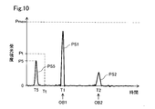
- FIG. 10 is an explanatory diagram illustrating a condition for determining the peak signal corresponding to the clutter by the optical ranging device of the fifth embodiment.
- the optical ranging device 200 as the first embodiment of the present disclosure is mounted on a moving body such as a vehicle and used.
- the optical ranging device 200 detects a distance, a relative velocity, and an angle from an object such as another vehicle, a pedestrian, or a building that exists in the set ranging range.
- the detection result of the optical ranging device 200 is used, for example, for vehicle operation control.
- the optical ranging device 200 includes a control device 100, and includes a light emitting unit 40, a scanning unit 50, and a light receiving unit 60 inside the housing 80.
- a window portion 82 that transmits laser light is provided on the wall surface of the housing 80.
- the light emitting unit 40 includes a laser diode as a light source for optical ranging, and emits a laser beam DL as an emitted light for ranging.
- a laser diode as a light source for optical ranging
- emits a laser beam DL as an emitted light for ranging As the light source of the light emitting unit 40, in addition to the laser diode, another light source such as a solid-state laser may be used.
- the scanning unit 50 functions as a so-called one-dimensional scanner.
- the scanning unit 50 includes a mirror 51 and a rotating unit 52.
- the mirror 51 is fixed to the rotating portion 52.
- the rotating unit 52 receives a control signal from the control device 100 and performs forward rotation and reverse rotation with the central axis AX as the rotation axis.
- the laser beam DL emitted from the light emitting unit 40 is reflected by the mirror 51, passes through the window unit 82, and is emitted to the outside of the housing 80.
- the laser beam DL scans within a predetermined range along the S direction shown in FIG. 1 by the mirror 51 accompanying the rotation of the rotating portion 52.
- the range in which the optical ranging device 200 scans the laser beam DL for ranging is also referred to as a scanning range RA below.
- the S direction is the scanning direction of the laser beam DL, and is parallel to the horizontal plane in the present embodiment.
- the V direction shown in FIG. 1 is the arrangement direction of the pixels 66, which will be described later.
- the V direction is a direction perpendicular to the S direction and is parallel to the vertical direction in the present embodiment.
- the light receiving unit 60 receives the incident light and outputs a detection signal corresponding to the light receiving intensity of the received incident light.
- the incident light includes a target within the scanning range RA, for example, reflected light RL corresponding to the laser light DL reflected by the object OB shown in FIG. 1, sunlight, street light, and other vehicle's light. Disturbed light may be included.
- the control device 100 is a microcomputer provided with a well-known microprocessor and memory.
- the microprocessor executes a program stored in advance in the memory, the control unit 110, the addition unit 120, the histogram generation unit 130, the peak detection unit 140, the pseudo-object determination unit 150, and the distance calculation unit 160 Realize the functions of each part.
- the control unit 110 executes drive control of the light emitting unit 40, the scanning unit 50, and the light receiving unit 60. More specifically, the control unit 110 has a command signal for causing the light emitting unit 40 to emit a laser diode, an address signal for activating the light receiving element for the light receiving unit 60, and a rotating unit for the scanning unit 50. A control signal for 52 is output.
- the adding unit 120 is a circuit that adds the signal strength of the light receiving element of the light receiving unit 60.
- the histogram generation unit 130 adds the addition results of the addition unit 120 a plurality of times to generate a histogram of the signal strength with respect to the time axis.
- the peak detection unit 140 analyzes the histogram input from the histogram generation unit 130 to detect the position of the peak signal with respect to the time of the signal corresponding to the reflected light RL.
- the peak signal in the histogram indicates the intensity of the reflected light pulse, and indicates that an object may exist at a position (distance) corresponding to the TOF (time of flight) corresponding to the peak signal.
- the position of the detected peak signal is output to the pseudo-object determination unit 150.
- the pseudo-object determination unit 150 determines whether or not the detected object is a pseudo-object by using the peak signal detected by the peak detection unit 140.
- the “pseudo-object” means an object that does not actually exist and is detected by the light receiving unit 60 by the multiple reflection of the emitted light emitted from the optical ranging device 200 between the object and the light receiving element. Pseudo-objects are also called "ghosts". When a vehicle equipped with an optical ranging device detects a pseudo object as an actual target, control for avoiding a collision with the pseudo object, such as brake control, can be executed.
- a high-intensity reflected light RL can be obtained.
- the reflected light RL of high intensity is incident on the light receiving element 68, a part of the reflected light RL is detected by the light receiving element 68 as one peak signal corresponding to the distance to the object.
- the reflected light RL that has not been received by the light receiving element 68 can, for example, be reflected on the surface of the light receiving element 68 without being incident on the light receiving element 68 and travel toward the object again.
- the reflected light that is reflected on the surface of the light receiving element 68 and travels toward the object again is hereinafter also referred to as “second reflected light”.
- second reflected light When the second reflected light is reflected by an object and enters the light receiving element 68, it is detected as a peak signal corresponding to a pseudo object different from the peak signal of the reflected light RL.
- the second reflected light When the second reflected light is not incident on the light receiving element 68 and is further reflected by the light receiving element 68, it is further detected as a peak signal different from the second reflected light, and can be repeated thereafter.
- the laser beam reciprocates between the optical ranging device 200 and the object by the number of times N (N is a natural number of 2 or more) reflected by the object due to the multiple reflections of the object and the light receiving element. Therefore, the pseudo-object can be detected as a peak signal at a position N times the distance from the optical ranging device 200 to the object.
- the distance calculation unit 160 uses the TOF to measure the distance to a target existing in the scanning range RA, for example, the object OB. More specifically, the distance calculation unit 160 determines the object OB from the time from the time when the laser light DL is emitted from the light emitting unit 40 to the time when the peak signal of the reflected light RL is received, that is, the flight time of the laser light DL. Calculate the distance to.
- the pseudo-object removal process described later is executed, and when the pseudo-object is detected by the pseudo-object determination unit 150, the distance calculation unit 160 causes the detection result corresponding to the pseudo-object. Is removed to detect the distance, and if no pseudo-object is detected, the distance is detected using the acquired peak signal.
- the configuration of the light receiving unit 60 will be described with reference to FIG.
- the light receiving unit 60 includes a plurality of pixels 66 on the light receiving surface.
- the pixels 66 are arranged so as to form a long rectangular shape along the V direction on a two-dimensional plane corresponding to the S direction and the V direction.
- the arrangement of the light receiving units 60 shown in FIG. 2 corresponds to the light receiving pixels for one slot in the scanning range RA of the laser beam DL.
- Each pixel 66 includes a plurality of light receiving elements 68.
- the pixels 66 are arranged by five light receiving elements 68 in each of the S direction and the V direction.
- a single photon avalanche diode (SPAD) is used as the light receiving element 68.
- SPAD photon avalanche diode
- the addition unit 120 obtains an addition value for each pixel 66 by counting the number of signals output from the plurality of light receiving elements 68 of each pixel 66.
- the pixel 66 may be composed of one light receiving element 68, or may include two or more arbitrary number of light receiving elements 68.
- the light receiving elements 68 may be arranged in any shape.
- a PIN photodiode may be used for the light receiving element 68 instead of the SPAD.
- the pseudo-object removal process executed by the optical ranging device 200 of the present embodiment will be described with reference to FIG.
- the pseudo-object removal process is started, for example, by turning on the power of the optical ranging device 200.
- the pseudo-object removal process is executed, for example, for each pixel 66 for each slot (direction) included in the scanning range RA.
- the flow chart shown in FIG. 3 shows an example of processing with one pixel 66 in one slot (direction) in the scanning range RA.
- the control device 100 drives and controls the light emitting unit 40, the scanning unit 50, and the light receiving unit 60 by the control unit 110 to detect a target within the scanning range RA and detect a distance (hereinafter, “measurement”). (Also referred to as “distance processing”) is started (step S10).
- the addition unit 120 counts the number of signals output from the light receiving element 68 of the pixel 66, and the histogram generation unit 130 generates a histogram of the signal intensity with respect to the time axis.
- the peak detection unit 140 detects the peak signal of the first object by analyzing the histogram and receiving the reflected light from the first object as one object in the scanning range RA (step S20).
- the peak detection unit 140 detects the first object, it confirms whether or not there is a peak signal corresponding to the second object in the histogram, that is, whether or not the second object is detected (step S30).
- the second object means an object that can be determined to be a pseudo object corresponding to the first object among the objects detected together with the first object.
- the distance is N times the distance to the first object (N is a natural number of 2 or more) on the extension of the straight line connecting the optical ranging device 200 and the first object, that is, in the emission direction of the laser beam DL.
- the object located in is determined to be the second object.
- the distance calculation unit 160 detects the distance using the detected peak signals of the first object and other objects (step S60), and completes the process.
- the pseudo-object determination unit 150 determines whether or not the detected second object is a pseudo-object (step S40).
- the pseudo-object determination unit 150 detects an object that does not transmit light, that is, an object that has light impermeableness (hereinafter, also referred to as a "third object"), and the second object is a third object.
- the second object is detected at a position farther from the optical ranging device 200, it is determined that the second object is a pseudo object.
- the third object includes various objects having light impermeable properties, such as a road, the ground, and a wall surface of a building. Whether or not the third object is detected may be determined from the result of distance measurement by the optical distance measuring device 200. For example, it is determined from the detection result of a detector other than the optical distance measuring device 200 such as a camera or radar. May be done.
- the distance calculation unit 160 excludes the peak signal corresponding to the second object from the distance calculation, and detects the first object and other objects. The distance is detected using the peak signal of the object (step S50), and the process is completed. Instead of the process of excluding the peak signal corresponding to the second object from the calculation of the distance, a process of deleting the peak signal corresponding to the second object from the histogram may be executed.
- the distance calculation unit 160 detects the distance using the peak signals of the detected first object and second object and other objects (step). S60), the process is completed.
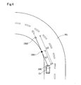
- FIG. 4 shows a state in which the vehicle C1 equipped with the optical ranging device 200 of the present embodiment is traveling on the road RS.
- FIG. 4 conceptually shows the first object OB1 and the second object OB2 as a pseudo object corresponding to the first object OB1.
- the first object OB1 is a so-called strong reflector that utilizes so-called retroreflection in which incident light is reflected toward a light source of incident light.
- the first object OB1 is also called, for example, a retroreflector, a corner cube, a retroreflector, a retroreflector, or the like.
- the intensity of the reflected light from the first object OB1 can be higher than usual.
- the first object OB1 is located at a distance D1 from the optical ranging device 200 toward the direction OL
- the second object OB2 is located at a distance D2 from the optical ranging device 200 toward the direction OL. positioned.
- the distance D2 corresponds to twice the distance D1.
- the optical ranging device 200 has completed the detection of the road RS as the third object while the vehicle C1 is traveling.
- the laser beam emitted for distance measurement in the direction OL is reflected by the first object OB1 among the objects on the direction OL.
- a part of the reflected light from the first object OB1 is received by the light receiving element 68 of the light receiving unit 60 and detected as the peak signal PS1 corresponding to the first object OB1.
- the distance calculation unit 160 calculates the distance D1 to the first object OB1 by using the TOF and the time T1 when the peak signal PS1 is detected.
- the first object OB1 is a strong reflective material, and the intensity of the reflected light from the first object OB1 is high. Therefore, a part of the reflected light from the first object OB1 is reflected on the surface of the light receiving unit 60 and travels in the direction OL as the second reflected light.
- the second reflected light is reflected by the first object OB1 and received by the light receiving element 68.
- the distance D2 is twice the distance D1 in the direction OL. It is detected as a peak signal PS2 corresponding to the second object OB2 at the position of.
- FIG. 6 conceptually shows a state in which the distance between the first object OB1 and the second object OB2 is detected by the optical ranging device 200 as viewed from the side surface side of the vehicle C1.
- the optical ranging device 200 detects the road RS together with the first object OB1 and the second object OB2.
- the pseudo-object determination unit 150 uses the detection result of the road RS and the detection result of the distance of the second object OB2 to determine whether or not the second object OB2 is at a position farther from the optical ranging device 200 than the road RS. Is determined.
- the second object OB2 is detected at a position farther from the optical ranging device 200 than the road RS which is the third object in the straight line OL.
- the pseudo-object determination unit 150 determines that the second object OB2 is a pseudo-object.
- the distance calculation unit 160 excludes the peak signal corresponding to the second object OB2 from the distance calculation, and detects the distance using the peak signal of the first object OB1.
- the first object OB1 and the second object OB2 are detected, and the second object OB2 corresponds to the first object OB1.
- the detection result of the second object OB2 is removed. Therefore, the influence of the pseudo object can be reduced and the target can be detected accurately. Preventing the vehicle equipped with the optical ranging device 200 from detecting the second object OB2 as an existing target, and suppressing or preventing the execution of control for avoiding a collision with a pseudo object. Can be done.
- the pseudo object determination unit 150 detects the road RS as a third object having light opacity, and the second object OB2 is an optical distance measuring device rather than the road RS.
- the second object OB2 is detected at a position away from 200, the second object OB2 is determined as a pseudo object.
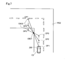
- the optical ranging device 200 of the second embodiment will be described with reference to FIG. 7.
- the method of determining the pseudo-object in step S40 of the pseudo-object removal process is different from that of the optical ranging device 200 of the first embodiment, and the other configurations are the same as those of the first embodiment. This is the same as the optical ranging device 200.
- the optical ranging device 200 of the present embodiment uses the result of tracking the relative position of the second object with respect to the first object when the second object is detected while the optical ranging device 200 is moving. Determine if the object is a pseudo-object. More specifically, the pseudo-object determination unit 150 tracks the relative position of the second object with respect to the first object within a predetermined period from the time when the second object is detected. The predetermined period is a moving period of the optical ranging device 200, and may be set to an arbitrary period. When the relative position of the second object with respect to the first object is maintained at a position that is N times the distance from the optical ranging device 200 to the first object, the pseudo-object determination unit 150 determines the second object. Judged as a pseudo object.
- the optical ranging device 200 is mounted on the vehicle C2.
- the optical ranging device 200 moves the position CP1, the position CP2, and the position CP3 on the road RS2 in this order within a predetermined period as the vehicle C2 travels.
- the optical ranging device 200 detects the first object OB21 which is a strong reflective material and also detects the second object OB22 at the position OP1.
- the optical ranging device 200 detects the first object OB21 at the position CP2, detects the second object OB22 at the position OP2, detects the first object OB21 at the position CP3, and detects the second object OB21 at the position OP3.
- OB22 is detected.
- the relative position of the second object OB22 with respect to the first object OB21 is the optical distance measuring device.
- the distance from 200 to the first object OB21 is maintained at twice the distance. Therefore, the pseudo-object determination unit 150 determines the second object OB22 as a pseudo-object.
- the distance measuring process is executed while the optical distance measuring device 200 is moving, and the second object OB22 is detected within a predetermined period from the time when the second object OB22 is detected.
- the pseudo-object determination unit 150 determines the second object when the relative position of the second object OB22 with respect to the first object OB21 maintains a distance N times the distance from the optical distance measuring device 200 to the first object OB21.
- OB2 is determined to be a pseudo object. It is possible to determine whether or not the second object OB2 is a pseudo object by utilizing the behavior of the second object OB2 while the optical ranging device 200 is moving. Therefore, it is possible to determine whether or not the second object OB2 is a pseudo object while the optical ranging device 200 is moving.
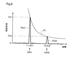
- the optical ranging device 200 of the third embodiment will be described with reference to FIG.
- the method of determining the pseudo-object in step S40 of the pseudo-object removal process is different from that of the optical ranging device 200 of the first embodiment, and the other configurations are the same as those of the first embodiment. This is the same as the optical ranging device 200.
- the optical ranging device 200 of the present embodiment uses the so-called light attenuation law, in which the intensity of light is inversely proportional to the square of the distance from the light source as a method for determining a pseudo object.
- the signal strength of the second object conforms to the so-called inverse square law with respect to the signal strength of the first object, it is determined that the second object is a pseudo object. More specifically, the signal strength of the second object located at a distance N times the distance from the optical ranging device 200 to the first object OB1 is the square of N with respect to the signal strength of the first object.
- it is inversely proportional it is determined that the second object is a pseudo object.
- the first object OB31 which is a strongly reflecting material located at a distance D31 from the optical ranging device 200, is detected as a peak signal PS31.
- the second object OB22 located at a distance D32 corresponding to twice the distance D31 from the optical distance measuring device 200 is detected as the peak signal PS32.
- the curve PL shown in FIG. 8 is a graph based on the distance D31 to the first object OB31 and is inversely proportional to the square of the ratio to the distance D31.
- the pseudo-object determination unit 150 determines that the second object OB32 is a pseudo-object when the signal strength of the second object OB32 is located on the curve PL.
- the signal strength of the second object OB32 is not limited to the case where it is located on the curve PL, and the signal strength of the second object OB32 is located within a predetermined range including the curve PL in consideration of detection error and the like. In some cases, it may be determined that the second object OB32 is a pseudo object.
- the pseudo-object determination unit 150 determines that the signal strength of the second object OB32 is inversely proportional to the square of N with respect to the signal strength of the first object OB31, and determines that the second object OB32 is a pseudo-object.
- the optical ranging device 200 of the present embodiment when the signal intensity P32 of the second object OB32 is inversely proportional to the square of N with respect to the signal intensity P31 of the first object OB31, a pseudo object determination is made.
- the unit 150 determines that the second object OB32 is a pseudo object. Whether or not the second object is a pseudo-object can be determined from the signal strength histogram, and the pseudo-object can be detected by a simple method.
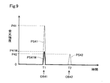
- the optical ranging device 200 of the fourth embodiment will be described with reference to FIG.
- the method of determining the pseudo-object in step S40 of the pseudo-object removal process is different from that of the optical ranging device 200 of the first embodiment, and the other configurations are the same as those of the first embodiment. This is the same as the optical ranging device 200.
- the optical ranging device 200 of the present embodiment reduces the output of the light emitting unit 40 from the output when the first object and the second object are detected after the first object and the second object are detected.
- (1) Executes distance measurement processing under distance measurement conditions.
- the optical distance measuring device 200 determines the number of times the detection signal is acquired from the light receiving unit 60 by the histogram generating unit 130 together with the first distance measuring condition or instead of the first distance measuring condition, for the first object and the second object.
- the distance measuring process under the second distance measuring condition may be executed to reduce the number of times of detection.
- the peak signal PS41 corresponding to the first object OB41 which is a strongly reflective material detected by the peak detection unit 140, and the second object located at a distance twice the distance to the first object OB41.
- the peak signal PS42 corresponding to OB42 is shown by a broken line.
- the control unit 110 controls the light emitting unit 40 to output the laser beam from the first object OB41 and the second object OB42.
- the distance is detected with the output reduced from the output at the time of detection.
- Distance measurement processing under at least one of the first distance measurement condition and the second distance measurement condition is also referred to as "strong reflector detection processing".
- the output of the laser beam reduced in the strong reflector detection process is set to such an output that the peak signal PS41W of the first object OB41 as the strong reflector can be detected.
- the signal intensity P41 of the peak signal PS41 corresponding to the first object OB41 is reduced, and the peak signal PS41W having the signal intensity P41W is obtained.
- the peak signal PS42 of the signal strength P42 corresponding to the second object OB42 disappears and is not detected as a peak signal.
- the strong reflector detection process is executed to determine whether or not the first object OB41 is detected, thereby determining whether or not the first object OB41 is detected. It is determined whether or not OB41 is a strongly reflective material.
- the pseudo-object determination unit 150 determines that the first object OB41 is a strong reflective material
- the pseudo-object determination unit 150 determines that the second object OB42 is a pseudo-object.
- the output of the laser beam is the output when the first object OB41 and the second object OB42 are detected.
- the first object OB41 is determined to be a strongly reflective material
- the second object OB42 is determined to be a pseudo object. Therefore, the pseudo object can be detected by a simple method.
- the optical ranging device 200 of the fifth embodiment will be described with reference to FIG.
- the optical ranging device 200 of the fifth embodiment is the optical ranging device 200 of the first embodiment in that it performs a clutter removing process for removing the clutter detection result in addition to the pseudo-object removing process of the first embodiment.
- the other configurations are the same as those of the optical ranging device 200 of the first embodiment.
- the “clutter” means the reflected light emitted from the light emitting unit 40 and reflected by the window portion 82 of the housing 80. Since the clutter can be detected as a peak signal by being incident on the light receiving unit 60, the distance measurement accuracy of the optical distance measuring device 200 may be lowered. Generally, the clutter is detected as a peak signal that is a short distance from the optical ranging device 200 and has a lower intensity than the reflected light from the object OB.
- FIG. 10 shows the peak signal PS5 corresponding to the clutter.
- the peak signal PS5 is detected together with the peak signal PS1 of the first object OB1 by the histogram analysis by the peak detection unit 140.
- the pseudo-object determination unit 150 detects when the detection distance of the detected peak signal is smaller than the predetermined time threshold value Tt and the light receiving intensity is smaller than the predetermined intensity threshold value Pt. It is determined that the peak signal is the peak signal corresponding to the clutter.
- the distance calculation unit 160 removes the detection result of the peak signal PS5 corresponding to the clutter and detects the distance.
- FIG. 10 shows the maximum value Pmax that the light receiving intensity can take.
- the maximum value Pmax is the total number of light receiving elements 68 per pixel used when creating a histogram. As described with reference to FIG. 2, one pixel 66 is composed of 5 ⁇ 5 light receiving elements 68.
- N is an integer of 2 or more
- the maximum value Pmax that the light receiving intensity can take is equal to N ⁇ 5 ⁇ 5 when the light receiving results obtained by N times of light emission are summed to create a histogram.
- the intensity threshold Pt is usually set to a value smaller than the maximum value Pmax that the light receiving intensity can take. In the present embodiment, the intensity threshold value Pt is set at a light receiving intensity of 50% of the maximum value Pmax.
- the intensity threshold Pt may be set to a value equal to the maximum value Pmax.
- the time threshold value Tt is set at an arbitrary distance that is a short distance from the optical distance measuring device 200.
- the time threshold value Tt may be set at a specific flight time corresponding to the distance of the optical path from the light emitting unit 40 to the window unit 82, and is based on the distance of the optical path from the light emitting unit 40 to the window unit 82 in consideration of an error or the like. May be set at a large distance.
- the time threshold value Tt is set at 1 meter from the light emitting unit 40, which is larger than the distance of the optical path from the light emitting unit 40 to the window unit 82.
- the peak signal due to the clutter is removed in addition to the detection result of the pseudo object during the distance measuring process. Therefore, it is possible to suppress a decrease in the distance measuring accuracy of the optical distance measuring device 200 due to the clutter, and to detect the target more accurately.
- the controls and methods thereof described in the present disclosure are realized by a dedicated computer provided by configuring a processor and memory programmed to perform one or more functions embodied by a computer program. May be done.
- the controls and methods thereof described in the present disclosure may be implemented by a dedicated computer provided by configuring the processor with one or more dedicated hardware logic circuits.
- the control unit and method thereof described in the present disclosure may be a combination of a processor and memory programmed to perform one or more functions and a processor composed of one or more hardware logic circuits. It may be realized by one or more dedicated computers configured.
- the computer program may be stored in a computer-readable non-transitional tangible recording medium as an instruction executed by the computer.
- the present disclosure is not limited to the above-described embodiment, and can be realized by various configurations within a range not deviating from the purpose.
- the technical features in the embodiments corresponding to the technical features described in the column of the outline of the invention may be used to solve some or all of the above-mentioned problems, or some or all of the above-mentioned effects. It is possible to replace or combine as appropriate to achieve this. Further, if the technical feature is not described as essential in the present specification, it can be deleted as appropriate.
Landscapes
- Engineering & Computer Science (AREA)
- Physics & Mathematics (AREA)
- General Physics & Mathematics (AREA)
- Computer Networks & Wireless Communication (AREA)
- Radar, Positioning & Navigation (AREA)
- Remote Sensing (AREA)
- Electromagnetism (AREA)
- Optical Radar Systems And Details Thereof (AREA)
- Traffic Control Systems (AREA)
Priority Applications (2)
| Application Number | Priority Date | Filing Date | Title |
|---|---|---|---|
| CN202180028772.4A CN115427831B (zh) | 2020-04-15 | 2021-04-01 | 光测距装置 |
| US18/046,772 US20230065210A1 (en) | 2020-04-15 | 2022-10-14 | Optical distance measuring device |
Applications Claiming Priority (2)
| Application Number | Priority Date | Filing Date | Title |
|---|---|---|---|
| JP2020-072685 | 2020-04-15 | ||
| JP2020072685A JP7306310B2 (ja) | 2020-04-15 | 2020-04-15 | 光測距装置 |
Related Child Applications (1)
| Application Number | Title | Priority Date | Filing Date |
|---|---|---|---|
| US18/046,772 Continuation US20230065210A1 (en) | 2020-04-15 | 2022-10-14 | Optical distance measuring device |
Publications (1)
| Publication Number | Publication Date |
|---|---|
| WO2021210415A1 true WO2021210415A1 (ja) | 2021-10-21 |
Family
ID=78083667
Family Applications (1)
| Application Number | Title | Priority Date | Filing Date |
|---|---|---|---|
| PCT/JP2021/014142 Ceased WO2021210415A1 (ja) | 2020-04-15 | 2021-04-01 | 光測距装置 |
Country Status (4)
| Country | Link |
|---|---|
| US (1) | US20230065210A1 (https=) |
| JP (1) | JP7306310B2 (https=) |
| CN (1) | CN115427831B (https=) |
| WO (1) | WO2021210415A1 (https=) |
Cited By (2)
| Publication number | Priority date | Publication date | Assignee | Title |
|---|---|---|---|---|
| WO2023181948A1 (ja) * | 2022-03-24 | 2023-09-28 | 株式会社デンソー | ノイズ除去装置、物体検出装置およびノイズ除去方法 |
| JP2023143756A (ja) * | 2022-03-24 | 2023-10-06 | 株式会社デンソー | ノイズ除去装置、物体検出装置およびノイズ除去方法 |
Families Citing this family (4)
| Publication number | Priority date | Publication date | Assignee | Title |
|---|---|---|---|---|
| JP7673763B2 (ja) * | 2022-03-23 | 2025-05-09 | 株式会社デンソー | 物体検出装置および物体検出方法 |
| WO2023181947A1 (ja) * | 2022-03-23 | 2023-09-28 | 株式会社デンソー | 物体検出装置および物体検出方法 |
| JP2023150501A (ja) * | 2022-03-31 | 2023-10-16 | 株式会社トプコン | 測量装置、測量方法および測量用プログラム。 |
| JP2024072098A (ja) * | 2022-11-15 | 2024-05-27 | 株式会社デンソー | 物体検知装置及び物体検知方法 |
Citations (7)
| Publication number | Priority date | Publication date | Assignee | Title |
|---|---|---|---|---|
| US5877997A (en) * | 1995-02-02 | 1999-03-02 | Croma Developments Limited | Pulse echo distance measurement |
| JPH1164497A (ja) * | 1997-08-15 | 1999-03-05 | Mitsubishi Electric Corp | レーダ装置 |
| JP2006030094A (ja) * | 2004-07-20 | 2006-02-02 | Keyence Corp | 光学式変位計 |
| JP2007304069A (ja) * | 2006-05-15 | 2007-11-22 | Honda Motor Co Ltd | 物体検知装置 |
| JP2016080649A (ja) * | 2014-10-22 | 2016-05-16 | 株式会社デンソー | 物体検知装置 |
| JP2019144210A (ja) * | 2018-02-23 | 2019-08-29 | コニカミノルタ株式会社 | 物体検出システム |
| JP2020020612A (ja) * | 2018-07-30 | 2020-02-06 | 株式会社リコー | 測距装置、測距方法、プログラム、移動体 |
Family Cites Families (3)
| Publication number | Priority date | Publication date | Assignee | Title |
|---|---|---|---|---|
| JP5251858B2 (ja) * | 2009-12-21 | 2013-07-31 | 株式会社デンソーウェーブ | レーザレーダ装置 |
| JP5741474B2 (ja) * | 2012-02-13 | 2015-07-01 | 株式会社デンソー | レーダ装置 |
| JPWO2017221909A1 (ja) * | 2016-06-21 | 2019-04-11 | コニカミノルタ株式会社 | 距離測定装置 |
-
2020
- 2020-04-15 JP JP2020072685A patent/JP7306310B2/ja active Active
-
2021
- 2021-04-01 CN CN202180028772.4A patent/CN115427831B/zh active Active
- 2021-04-01 WO PCT/JP2021/014142 patent/WO2021210415A1/ja not_active Ceased
-
2022
- 2022-10-14 US US18/046,772 patent/US20230065210A1/en active Pending
Patent Citations (7)
| Publication number | Priority date | Publication date | Assignee | Title |
|---|---|---|---|---|
| US5877997A (en) * | 1995-02-02 | 1999-03-02 | Croma Developments Limited | Pulse echo distance measurement |
| JPH1164497A (ja) * | 1997-08-15 | 1999-03-05 | Mitsubishi Electric Corp | レーダ装置 |
| JP2006030094A (ja) * | 2004-07-20 | 2006-02-02 | Keyence Corp | 光学式変位計 |
| JP2007304069A (ja) * | 2006-05-15 | 2007-11-22 | Honda Motor Co Ltd | 物体検知装置 |
| JP2016080649A (ja) * | 2014-10-22 | 2016-05-16 | 株式会社デンソー | 物体検知装置 |
| JP2019144210A (ja) * | 2018-02-23 | 2019-08-29 | コニカミノルタ株式会社 | 物体検出システム |
| JP2020020612A (ja) * | 2018-07-30 | 2020-02-06 | 株式会社リコー | 測距装置、測距方法、プログラム、移動体 |
Cited By (3)
| Publication number | Priority date | Publication date | Assignee | Title |
|---|---|---|---|---|
| WO2023181948A1 (ja) * | 2022-03-24 | 2023-09-28 | 株式会社デンソー | ノイズ除去装置、物体検出装置およびノイズ除去方法 |
| JP2023143756A (ja) * | 2022-03-24 | 2023-10-06 | 株式会社デンソー | ノイズ除去装置、物体検出装置およびノイズ除去方法 |
| JP7673764B2 (ja) | 2022-03-24 | 2025-05-09 | 株式会社デンソー | ノイズ除去装置、物体検出装置およびノイズ除去方法 |
Also Published As
| Publication number | Publication date |
|---|---|
| JP2021169944A (ja) | 2021-10-28 |
| CN115427831A (zh) | 2022-12-02 |
| JP7306310B2 (ja) | 2023-07-11 |
| CN115427831B (zh) | 2025-03-25 |
| US20230065210A1 (en) | 2023-03-02 |
Similar Documents
| Publication | Publication Date | Title |
|---|---|---|
| JP7306310B2 (ja) | 光測距装置 | |
| JP7578031B2 (ja) | 測距装置 | |
| CN112219131B (zh) | 光学测距装置及其方法 | |
| JP7383815B2 (ja) | Lidarデバイスにおけるレトロリフレクターの検出および回避 | |
| CN106030243A (zh) | 距离测量装置和视差计算系统 | |
| WO2019163673A1 (ja) | 光測距装置 | |
| TW200918929A (en) | Procedure and device to determining a distance by means of an opto-electronic image sensor | |
| US20200300988A1 (en) | Electronic apparatus and method | |
| JP2021196342A (ja) | 測距装置 | |
| CN118786358A (zh) | 用于具有自适应光晕校正的固态LiDAR的系统和方法 | |
| US20250271556A1 (en) | Object detection device and object detection method | |
| JP6186863B2 (ja) | 測距装置及びプログラム | |
| JP2020187042A (ja) | 光測距装置 | |
| JPH09211108A (ja) | 車両用レーザレーダ装置 | |
| WO2024120491A1 (en) | Method and apparatus for detecting obstruction for lidar, and storage medium | |
| WO2021194887A1 (en) | Scanning lidar systems with flood illumination for near-field detection | |
| JP7804190B2 (ja) | 距離計測装置 | |
| US20230036431A1 (en) | BLOOM COMPENSATION IN A LIGHT DETECTION AND RANGING (LiDAR) SYSTEM | |
| CN113678021A (zh) | 测距装置以及测距装置中的异常判定方法 | |
| JP6725982B2 (ja) | 障害物判定装置 | |
| JP2024004277A (ja) | 物体検出装置及び車両制御システム | |
| US12146764B2 (en) | Ranging method and range finder | |
| JP7483548B2 (ja) | 電磁波検出装置 | |
| JP2025125616A (ja) | センサシステム、移動体、センサシステムの制御方法、センサシステムの制御プログラム、および、コンピュータプログラムを記録したコンピュータ読み取り可能な記録媒体 | |
| WO2023181308A1 (ja) | コンピュータシステム、方法およびプログラム |
Legal Events
| Date | Code | Title | Description |
|---|---|---|---|
| 121 | Ep: the epo has been informed by wipo that ep was designated in this application |
Ref document number: 21787543 Country of ref document: EP Kind code of ref document: A1 |
|
| NENP | Non-entry into the national phase |
Ref country code: DE |
|
| 122 | Ep: pct application non-entry in european phase |
Ref document number: 21787543 Country of ref document: EP Kind code of ref document: A1 |
|
| WWG | Wipo information: grant in national office |
Ref document number: 202180028772.4 Country of ref document: CN |